NREL is a national laboratory of the U.S. Department of Energy, Office of Energy Efficiency and Renewable Energy, operated by the Alliance for Sustainable Energy, LLC. Performance and Reliability of Interface Materials for Automotive Power Electronics Sreekant Narumanchi National Renewable Energy Laboratory [email protected] (303) 275-4062 NREL Team members: Doug DeVoto, Mark Mihalic, Paul Paret Industry Session Applied Power Electronics Conference Long Beach, CA March 19, 2013 This presentation does not contain any proprietary or confidential information

Welcome message from author
This document is posted to help you gain knowledge. Please leave a comment to let me know what you think about it! Share it to your friends and learn new things together.
Transcript
NREL is a national laboratory of the U.S. Department of Energy, Office of Energy Efficiency and Renewable Energy, operated by the Alliance for Sustainable Energy, LLC.
Performance and Reliability of Interface Materials for Automotive Power Electronics
Sreekant Narumanchi National Renewable Energy Laboratory [email protected] (303) 275-4062
NREL Team members: Doug DeVoto, Mark Mihalic, Paul Paret
Industry Session Applied Power Electronics Conference Long Beach, CA March 19, 2013
This presentation does not contain any proprietary or confidential information
2
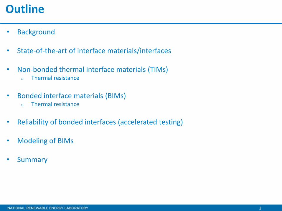
Outline • Background • State-of-the-art of interface materials/interfaces • Non-bonded thermal interface materials (TIMs)
o Thermal resistance
• Bonded interface materials (BIMs)
o Thermal resistance
• Reliability of bonded interfaces (accelerated testing)
• Modeling of BIMs
• Summary
3
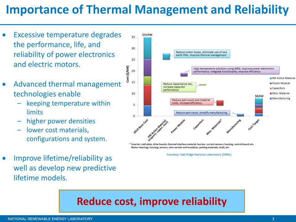
Importance of Thermal Management and Reliability Excessive temperature degrades
the performance, life, and reliability of power electronics and electric motors.
Advanced thermal management technologies enable – keeping temperature within
limits – higher power densities – lower cost materials,
configurations and system.
Improve lifetime/reliability as well as develop new predictive lifetime models.
Reduce cost, improve reliability
Courtesy: Oak Ridge National Laboratory (ORNL)
4
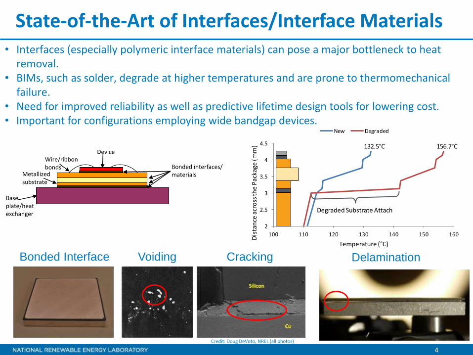
State-of-the-Art of Interfaces/Interface Materials • Interfaces (especially polymeric interface materials) can pose a major bottleneck to heat
removal. • BIMs, such as solder, degrade at higher temperatures and are prone to thermomechanical
failure. • Need for improved reliability as well as predictive lifetime design tools for lowering cost. • Important for configurations employing wide bandgap devices.
Metallized substrate
Base plate/heat exchanger
Device
Bonded interfaces/ materials
Wire/ribbon bonds
Delamination Voiding Cracking Bonded Interface
2
2.5
3
3.5
4
4.5
100 110 120 130 140 150 160
Dis
tan
ce a
cro
ss th
e P
acka
ge (m
m)
Temperature (°C)
New Degraded
Degraded Substrate Attach
132.5°C 156.7°C
Credit: Doug DeVoto, NREL (all photos)
5
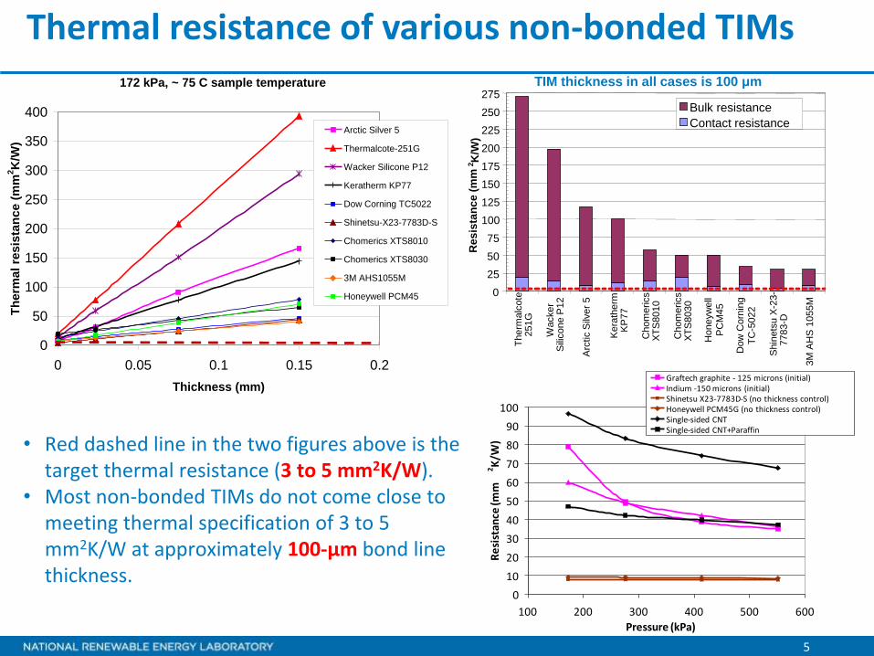
Thermal resistance of various non-bonded TIMs
0
50
100
150
200
250
300
350
400
0 0.05 0.1 0.15 0.2
Thickness (mm)
Th
erm
al
res
ista
nc
e (
mm
2K
/W)
Arctic Silver 5
Thermalcote-251G
Wacker Silicone P12
Keratherm KP77
Dow Corning TC5022
Shinetsu-X23-7783D-S
Chomerics XTS8010
Chomerics XTS8030
3M AHS1055M
Honeywell PCM45
172 kPa, ~ 75 C sample temperature TIM thickness in all cases is 100 μm
0
10
20
30
40
50
60
70
80
90
100
100 200 300 400 500 600
Pressure (kPa)
Re
sist
ance
(mm
2K
/W)
Graftech graphite - 125 microns (initial)Indium -150 microns (initial)Shinetsu X23-7783D-S (no thickness control)Honeywell PCM45G (no thickness control)Single-sided CNTSingle-sided CNT+Paraffin
• Red dashed line in the two figures above is the target thermal resistance (3 to 5 mm2K/W).
• Most non-bonded TIMs do not come close to meeting thermal specification of 3 to 5 mm2K/W at approximately 100-μm bond line thickness.
0
25
50
75
100
125
150
175
200
225
250
275
Th
erm
alc
ote
251G
Wacker
Sili
cone P
12
Arc
tic S
ilver
5
Kera
therm
K
P77
Chom
erics
XT
S8010
Chom
erics
XT
S8030
Honeyw
ell
PC
M45
Dow
Corn
ing
TC
-5022
Shin
ets
u X
-23-
7783-D
3M
AH
S 1
055M
Res
ista
nc
e (
mm
2 K
/W)
Bulk resistance
Contact resistance
6
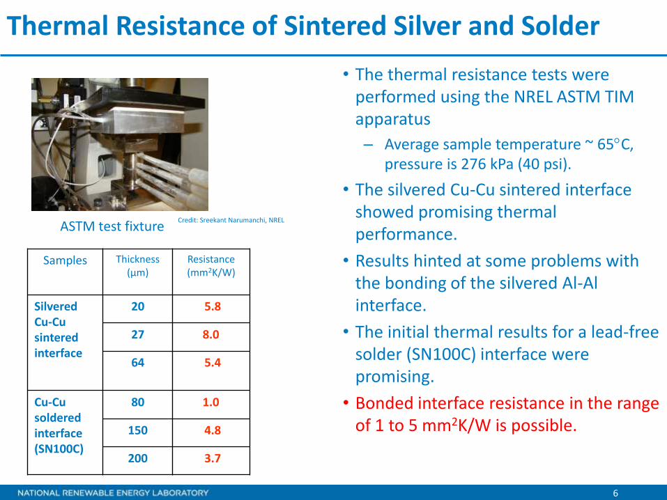
Thermal Resistance of Sintered Silver and Solder
Samples Thickness (µm)
Resistance (mm2K/W)
Silvered Cu-Cu sintered interface
20 5.8
27 8.0
64 5.4
Cu-Cu soldered interface (SN100C)
80 1.0
150 4.8
200 3.7
• The thermal resistance tests were performed using the NREL ASTM TIM apparatus
– Average sample temperature ~ 65C, pressure is 276 kPa (40 psi).
• The silvered Cu-Cu sintered interface showed promising thermal performance.
• Results hinted at some problems with the bonding of the silvered Al-Al interface.
• The initial thermal results for a lead-free solder (SN100C) interface were promising.
• Bonded interface resistance in the range of 1 to 5 mm2K/W is possible.
ASTM test fixture Credit: Sreekant Narumanchi, NREL
7
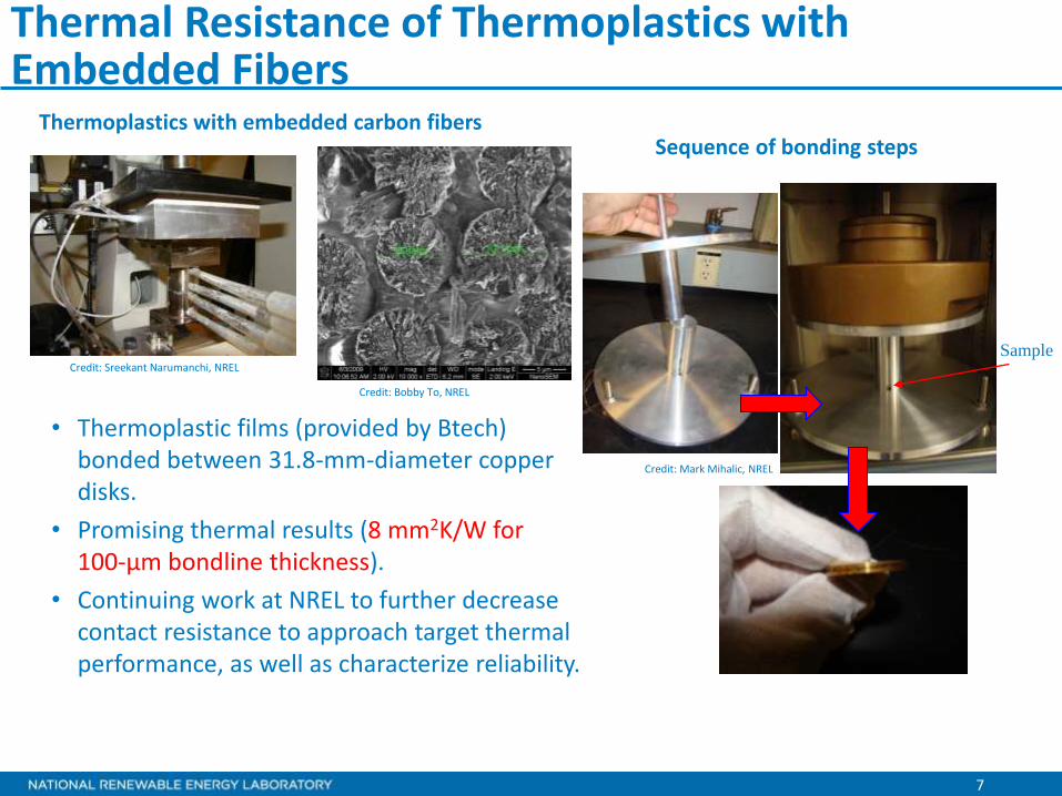
Thermal Resistance of Thermoplastics with Embedded Fibers
Sample
Thermoplastics with embedded carbon fibers
• Thermoplastic films (provided by Btech) bonded between 31.8-mm-diameter copper disks.
• Promising thermal results (8 mm2K/W for 100-µm bondline thickness).
• Continuing work at NREL to further decrease contact resistance to approach target thermal performance, as well as characterize reliability.
Sequence of bonding steps
Credit: Sreekant Narumanchi, NREL
Credit: Bobby To, NREL
Credit: Mark Mihalic, NREL
8
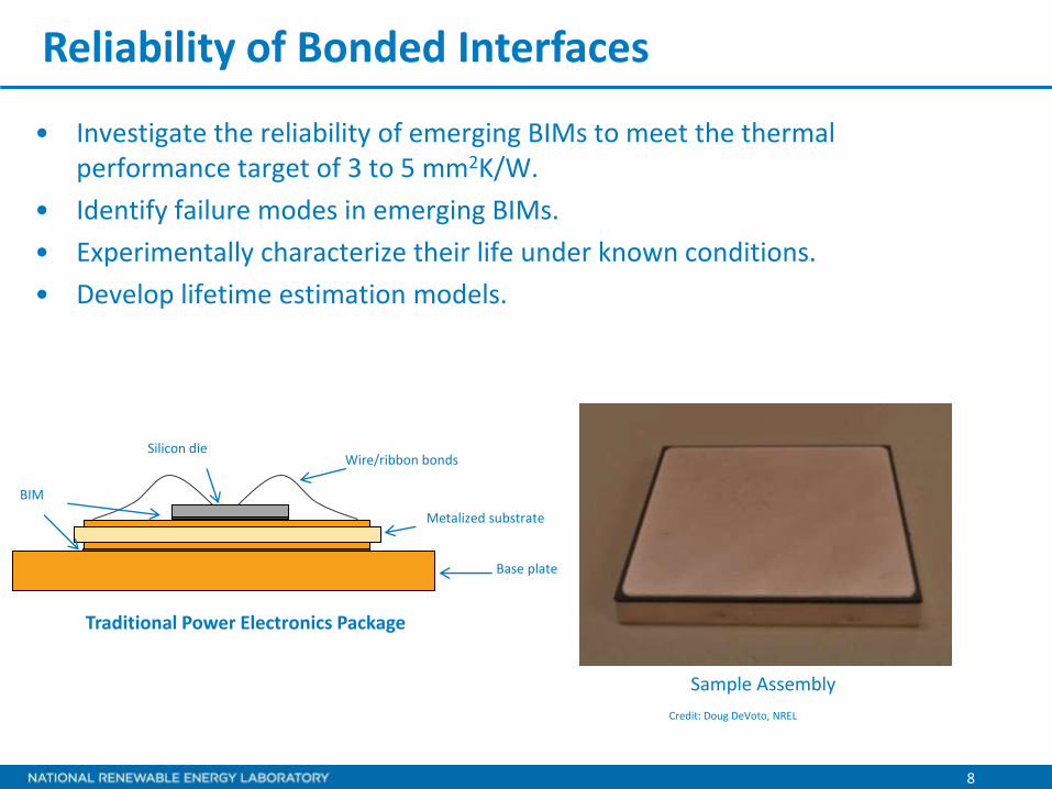
Reliability of Bonded Interfaces
• Investigate the reliability of emerging BIMs to meet the thermal performance target of 3 to 5 mm2K/W.
• Identify failure modes in emerging BIMs.
• Experimentally characterize their life under known conditions.
• Develop lifetime estimation models.
Sample Assembly
Traditional Power Electronics Package
Silicon die
Metalized substrate
Base plate
BIM
Wire/ribbon bonds
Credit: Doug DeVoto, NREL
9
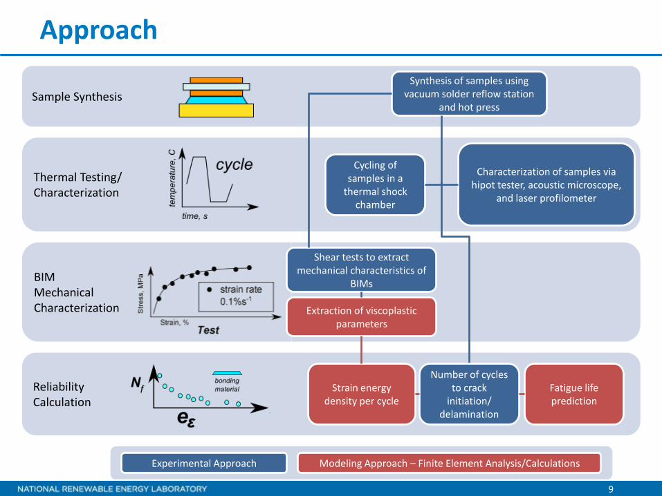
Approach
BIM Mechanical Characterization
Sample Synthesis
Reliability Calculation
Thermal Testing/ Characterization
Synthesis of samples using vacuum solder reflow station
and hot press
Cycling of samples in a
thermal shock chamber
Characterization of samples via hipot tester, acoustic microscope,
and laser profilometer
Shear tests to extract mechanical characteristics of
BIMs
Number of cycles to crack
initiation/ delamination
Fatigue life prediction
Strain energy density per cycle
Extraction of viscoplastic parameters
Experimental Approach Modeling Approach – Finite Element Analysis/Calculations
10
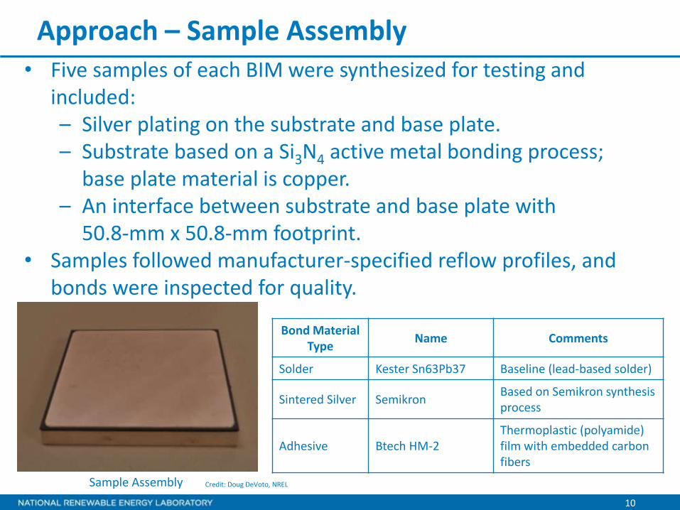
Approach – Sample Assembly • Five samples of each BIM were synthesized for testing and
included: – Silver plating on the substrate and base plate. – Substrate based on a Si3N4 active metal bonding process;
base plate material is copper. – An interface between substrate and base plate with
50.8-mm x 50.8-mm footprint. • Samples followed manufacturer-specified reflow profiles, and
bonds were inspected for quality.
Sample Assembly
Bond Material Type
Name Comments
Solder Kester Sn63Pb37 Baseline (lead-based solder)
Sintered Silver Semikron Based on Semikron synthesis process
Adhesive Btech HM-2 Thermoplastic (polyamide) film with embedded carbon fibers
Credit: Doug DeVoto, NREL
11
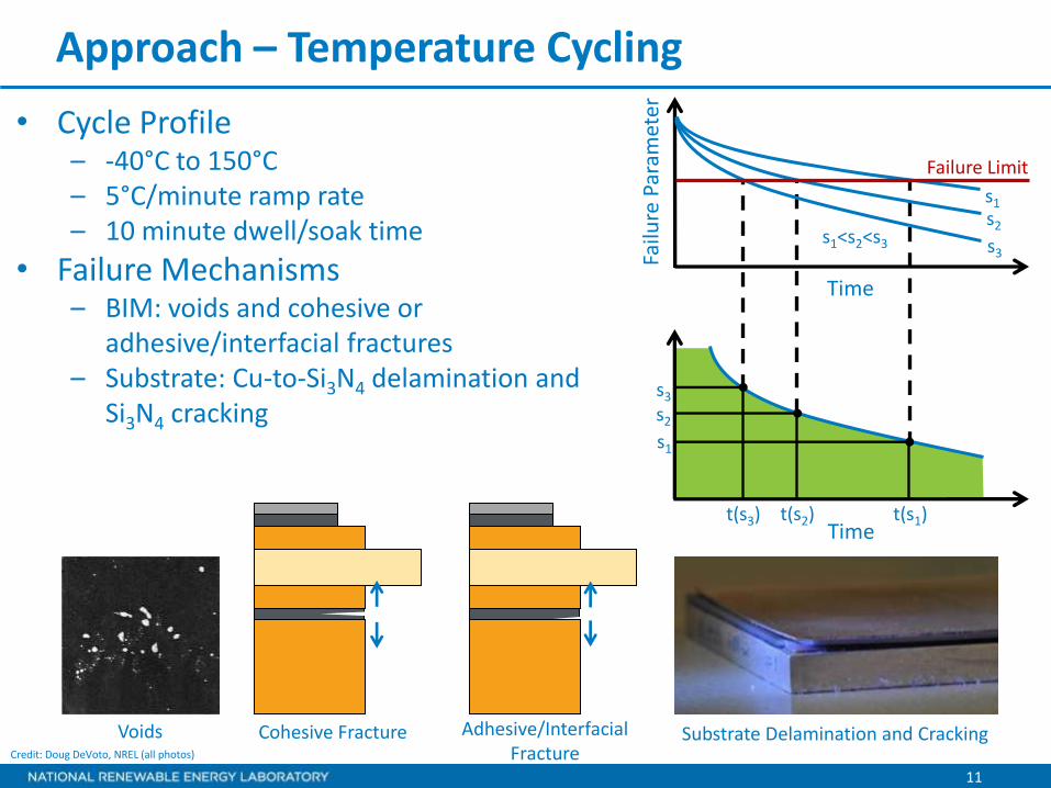
Approach – Temperature Cycling
• Cycle Profile – -40°C to 150°C – 5°C/minute ramp rate – 10 minute dwell/soak time
• Failure Mechanisms – BIM: voids and cohesive or
adhesive/interfacial fractures – Substrate: Cu-to-Si3N4 delamination and
Si3N4 cracking
Cohesive Fracture Voids Substrate Delamination and Cracking Adhesive/Interfacial Fracture
Time
Failu
re P
aram
eter
Time
Failure Limit
s1
s2
s3 s1<s2<s3
s3
s2
s1
t(s3) t(s2) t(s1)
Credit: Doug DeVoto, NREL (all photos)
12
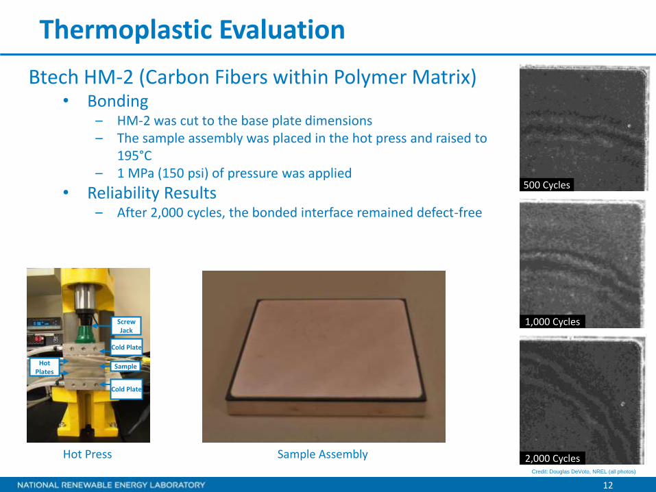
Thermoplastic Evaluation
Btech HM-2 (Carbon Fibers within Polymer Matrix) • Bonding
– HM-2 was cut to the base plate dimensions – The sample assembly was placed in the hot press and raised to
195°C – 1 MPa (150 psi) of pressure was applied
• Reliability Results – After 2,000 cycles, the bonded interface remained defect-free
Credit: Douglas DeVoto, NREL (all photos)
500 Cycles
1,000 Cycles
2,000 Cycles
Cold Plate
Sample Hot Plates
Cold Plate
Screw Jack
Hot Press Sample Assembly
13
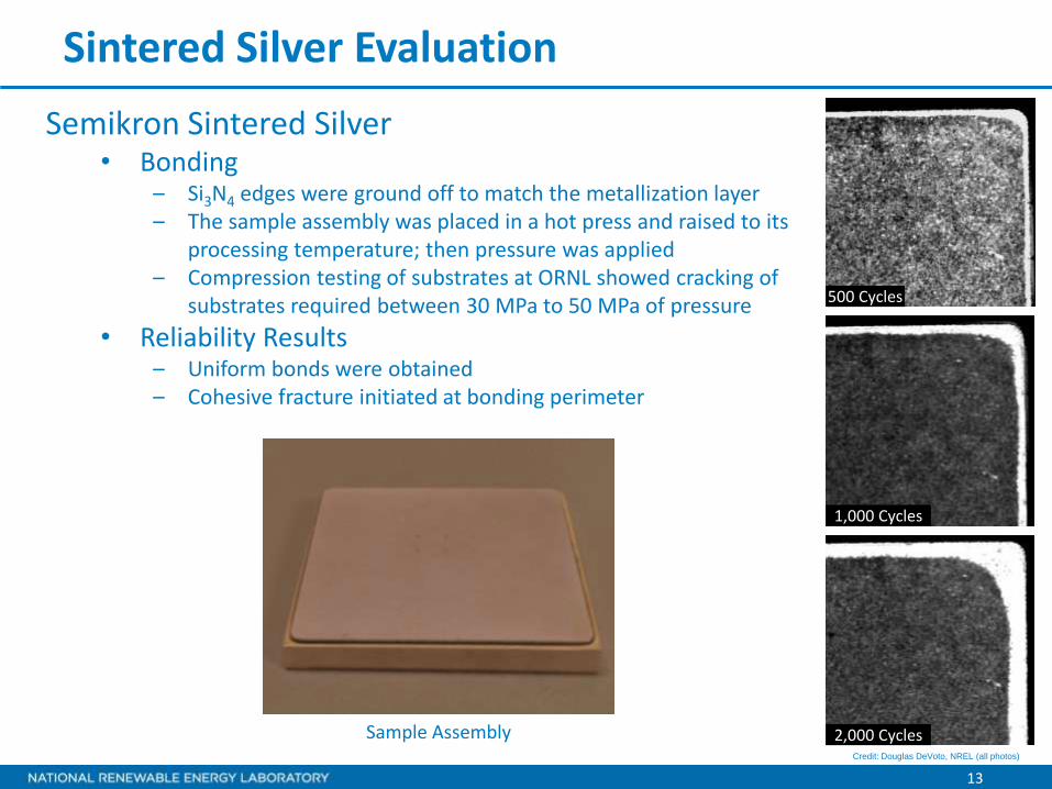
500 Cycles
1,000 Cycles
2,000 Cycles
Semikron Sintered Silver • Bonding
– Si3N4 edges were ground off to match the metallization layer – The sample assembly was placed in a hot press and raised to its
processing temperature; then pressure was applied – Compression testing of substrates at ORNL showed cracking of
substrates required between 30 MPa to 50 MPa of pressure
• Reliability Results – Uniform bonds were obtained – Cohesive fracture initiated at bonding perimeter
Sample Assembly
Sintered Silver Evaluation
Credit: Douglas DeVoto, NREL (all photos)
14
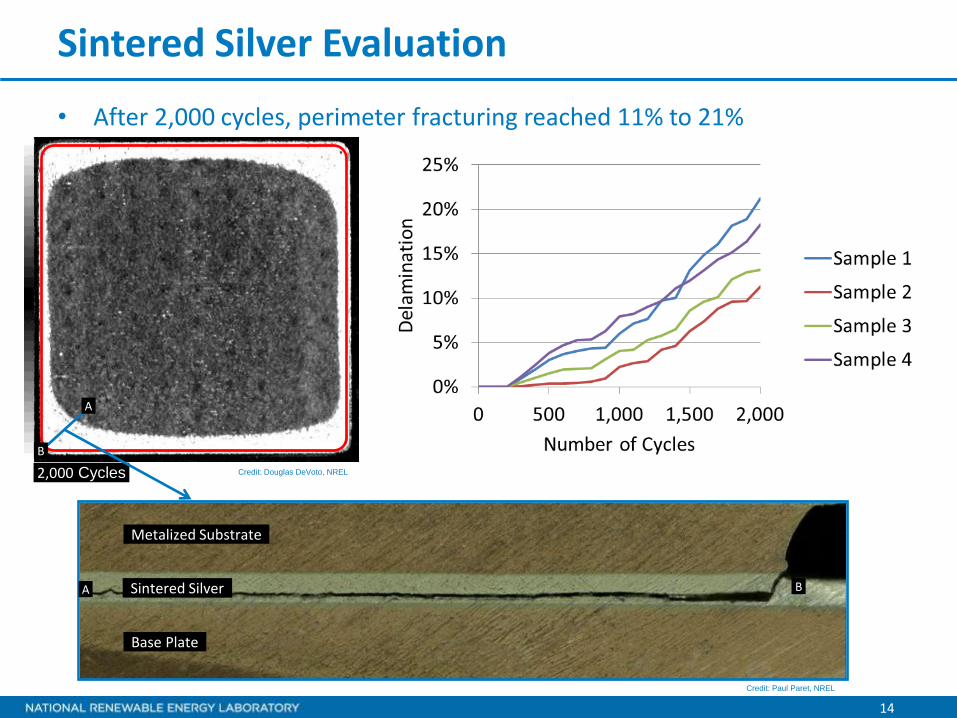
• After 2,000 cycles, perimeter fracturing reached 11% to 21%
2,000 Cycles
Sintered Silver Evaluation
Credit: Paul Paret, NREL
Credit: Douglas DeVoto, NREL
Metalized Substrate
Base Plate
Sintered Silver
A
B
A B
15
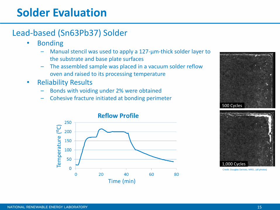
Solder Evaluation
Lead-based (Sn63Pb37) Solder • Bonding
– Manual stencil was used to apply a 127-µm-thick solder layer to the substrate and base plate surfaces
– The assembled sample was placed in a vacuum solder reflow oven and raised to its processing temperature
• Reliability Results – Bonds with voiding under 2% were obtained – Cohesive fracture initiated at bonding perimeter
500 Cycles
1,000 Cycles Credit: Douglas DeVoto, NREL (all photos)
16
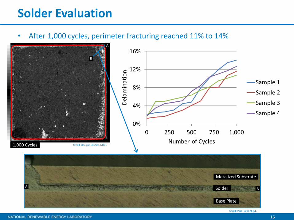
• After 1,000 cycles, perimeter fracturing reached 11% to 14%
1,000 Cycles
Solder Evaluation
Credit: Paul Paret, NREL
Credit: Douglas DeVoto, NREL
Metalized Substrate
Base Plate
Solder
A
B
A B
17
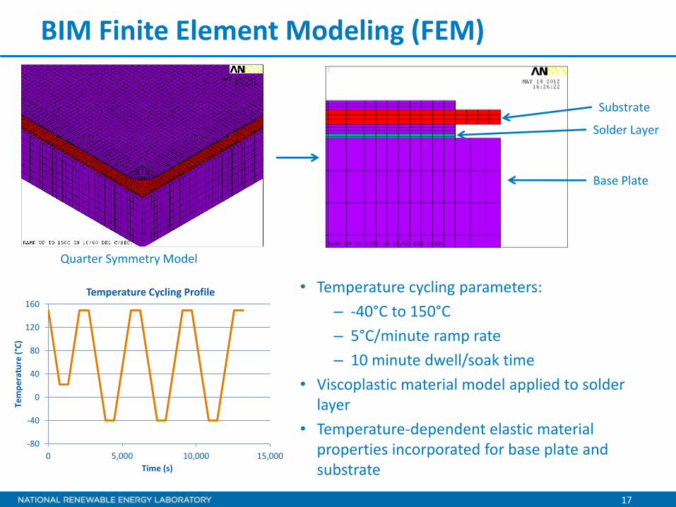
BIM Finite Element Modeling (FEM)
-80
-40
0
40
80
120
160
0 5,000 10,000 15,000
Tem
pe
ratu
re (
°C)
Time (s)
Temperature Cycling Profile • Temperature cycling parameters:
– -40°C to 150°C
– 5°C/minute ramp rate
– 10 minute dwell/soak time
• Viscoplastic material model applied to solder layer
• Temperature-dependent elastic material properties incorporated for base plate and substrate
Base Plate
Solder Layer
Substrate
Quarter Symmetry Model
18
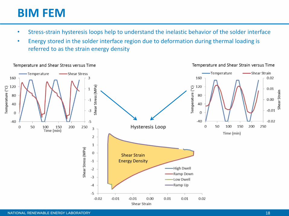
BIM FEM
• Stress-strain hysteresis loops help to understand the inelastic behavior of the solder interface
• Energy stored in the solder interface region due to deformation during thermal loading is referred to as the strain energy density
Shear Strain Energy Density
19
BIM FEM
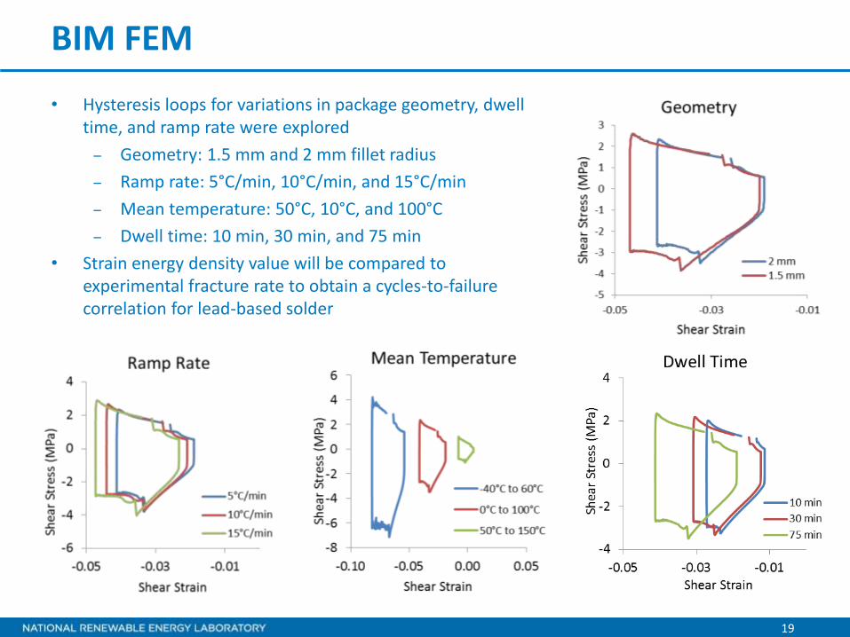
• Hysteresis loops for variations in package geometry, dwell time, and ramp rate were explored
– Geometry: 1.5 mm and 2 mm fillet radius
– Ramp rate: 5°C/min, 10°C/min, and 15°C/min
– Mean temperature: 50°C, 10°C, and 100°C
– Dwell time: 10 min, 30 min, and 75 min
• Strain energy density value will be compared to experimental fracture rate to obtain a cycles-to-failure correlation for lead-based solder
20
Summary
• TIMs/BIMs are a key enabling technology for compact, light-weight, low-cost,
reliable packaging and for high-temperature coolant and air-cooling technical
pathways.
• Characterization of thermal performance of TIMs/BIMs
– 3 to 5 mm2K/W resistance at 100 μm is a difficult target for non-bonded TIMs
– BIMs can meet this thermal target immediately after bonding – main question
is reliability
• Characterization of reliability of BIMs
– Synthesis of various joints between substrates and base plate, thermal
shock/temperature cycling, high-potential test and joint inspection (C-SAM),
and strain energy density versus cycles-to-failure models
– Thermoplastic BIM is very reliable after 2,000 cycles, sintered silver BIM
showing some significant edge delamination
• Initiated FEM for solder-bonded interface geometries – ultimate goal is to develop
predictive lifetime model for BIM.
21
Summary
• Current/Future Work
– Complete 2,000 thermal cycles on all selected materials using Si3N4-based substrates
– Report on reliability of each BIM under specified accelerated test conditions
– Derive viscoplastic parameters for lead-based and lead-free solders from double-lap shear test experiments
– Develop strain energy density versus cycles-to-failure predictive lifetime model for lead-based solder
– Expand strain energy density versus cycles-to-failure predictive lifetime model to lead-free solders
– Improve process for large-area sintered silver-based interface, and eventually develop predictive lifetime model
For more information contact: Principal Investigator Douglas DeVoto [email protected] Phone: (303) 275-4256 APEEM Task Leader Sreekant Narumanchi [email protected] Phone: (303) 275-4062
Acknowledgments: Susan Rogers and Steven Boyd U.S. Department of Energy Team Members: Mark Mihalic Paul Paret Collaborations: Semikron Btech Curamik Delphi GM Virginia Tech ORNL Heraeus Kyocera Shin-etsu Dow Corning 3M Parker Chomerics
Related Documents