Serial-number CSL670/671: __________________________ Serial-number CPD600: __________________________ The Crypton Test Lane Class 7 Automotive-Lift CSL670/671 Axle play detector CPD600 Operating Instructions and Documentation TES1519/E

Welcome message from author
This document is posted to help you gain knowledge. Please leave a comment to let me know what you think about it! Share it to your friends and learn new things together.
Transcript

Serial-number CSL670/671: __________________________
Serial-number CPD600: __________________________
The Crypton Test Lane Class 7 Automotive-Lift CSL670/671
Axle play detector CPD600 Operating Instructions and Documentation
TES1519/E

Operating Instruction and Documentation
CSL670/671
- 2 – TES1519/E
Contents
Foreword ............................................................................................................................................................. 3 Record of installation ........................................................................................................................................... 5 Record of Handover ............................................................................................................................................ 6
1. General Information .................................................................................................................................. 7 1.1 Installation and service checks of the automotive lift ..................................................................................... 7 1.2 Warning Symbols .......................................................................................................................................... 7
2. Master document of the automotive lift ..................................................................................................... 8 2.1 Lift–manufacturer Crypton .............................................................................................................. 8 2.2 Application ..................................................................................................................................................... 8 2.3 Changes to the Lift Construction ................................................................................................................... 8 2.4 Re positioning of the automotive lift ............................................................................................................... 8 2.5 Crypton Declaration of conformity ................................................................................................................. 9
3. Technical Information ............................................................................................................................. 10
3.1 Technical ratings ......................................................................................................................................... 10 3.2 Safety devices ............................................................................................................................................. 11 3.3 Data sheet - CSL670/671 ........................................................................................................................... 12 3.4 Floor Plan - CSL670/671 ............................................................................................................................ 13 3.5 Data sheet - Play Detector CPD600 ............................................................................................................ 14 3.6 Electrical Circuit Diagrams .......................................................................................................................... 15 3.6.1 Electrical Circuit Diagrams Standard Version ........................................................................................... 37 3.6.2 Electrical Circuit Diagrams Versions with wireless lamp ........................................................................... 25 3.7 Overview of the fuses in Crypten lifts......................................................................................................... 38 3.8 Hydraulic Diagram ....................................................................................................................................... 39 3.8.1 Hydraulic parts list .................................................................................................................................... 40 3.9 Pneumatic Diagram ..................................................................................................................................... 41
4. Safety regulations................................................................................................................................... 42
4.1 General safety-regulations ........................................................................................................................... 42 4.2 Additional safety-regulations ........................................................................................................................ 42
5. Operating Instructions ............................................................................................................................ 43 5.1 Lifting the vehicle ......................................................................................................................................... 43 5.2 Lowering the vehicle .................................................................................................................................... 44 5.3 Lowering onto the safety ratchet (latch) ....................................................................................................... 44 5.4 Manual equalisation of the lift platforms...................................................................................................... 45 5.5 Play detector ................................................................................................................................................ 46 5.6 Function test before first initiation ................................................................................................................ 47
6. Troubleshooting...................................................................................................................................... 47 6.1 Lowering onto an obstacle ........................................................................................................................... 48 6.2 Emergency lowering .................................................................................................................................... 48 6.2.1 Emergency lowering of the automotive lift ................................................................................................ 49
7. Inspection and Maintenance .................................................................................................................. 50 7.1 Maintenance schedule for the lift ................................................................................................................. 50 7.2 Maintenance schedule for the play detector ................................................................................................ 55 7.3 How often must the lift be cleaned? ............................................................................................................. 55
8. Security check ........................................................................................................................................ 56 9. Installation and Initiation ......................................................................................................................... 57
9.1 Installation of the lift ..................................................................................................................................... 57 9.2 Regulations for the installation ..................................................................................................................... 57 9.3 Erection and doweling (Masonry bolting) the lift .......................................................................................... 57 9.4 Initiation ....................................................................................................................................................... 58 9.5 Changing of the place of installation ............................................................................................................ 58 First security check before installation ............................................................................................................... 62 Regular security check and Maintenance .......................................................................................................... 63 Regular security check and Maintenance .......................................................................................................... 64 Extraordinary security check .............................................................................................................................. 74
Spare part list ............................................................................................................................................. 74 AFTER SALES SERVICE .................................................................................................................................. 97

Operating Instruction and Documentation
CSL670/671
- 3 – TES1519/E
Foreword
CRYPTON-products are a result of long-standing experiences.
The high quality and the superior concept guarantee them reliability, a long lift time and the
economic business.
To avoid unnecessary damages and dangers, read the operating instructions and follow the
instructions.
Do not use for any other purpose other than described otherwise the guarantee will become invalid.
Crypton is not liable for damage or injury arising from misuse. The user carries the risk
himself.
Notes for the user:
- Observe and comply with all the instructions in the operating manual
- Please follow the inspection and maintenance procedure as well as the prescribed tests
- The instruction for use should be observed by all persons working with the lift.
- The chapter “Safety/accident Prevention“ should be especially observed.
- In addition to the safety remarks included in the instructions for use, the local valid regulations
and instructions at the location of operation should also be observed.
Obligations of the operator:
The operator is obliged to allow only those persons complying to the following requirements to work
with the unit.
- Being well acquainted with the basic regulations concerning labour safety and accident
prevention and being trained to operate the unit.
- Having read and understood the chapter concerning safety and warning instructions and
confirmed that by their signature.
Dangers when operating with the lift:
The CRYPTON-Lifts are designed and built according to technical standard and the approved
regulations for technical security. Yet, danger for body and life of the operator may occur when using
the lift carelessly.
The lift must only be operated:
- for its appropriate use
- in an unobjectionable condition concerning technical security.

Operating Instruction and Documentation
CSL670/671
- 4 – TES1519/E
Organisation requirements
- The instructions for use are constantly to be kept at the place of operation, being at hand
at ALL times.
- In addition to the instructions for use, rules pertaining to other regulations i.e. accident
prevention and environmental rules are to be observed and directed.
- All personnel should be safety and danger alert by occasionally reading and by observing the
instructions for use, this act should be recorded.
- As far as required and ordered by regulations, personal protective equipment and clothes are to
be worn.
- All safety and danger warnings on or near the lift are to be observed!
- Spare parts must comply with technical requirements laid down by the manufacturer.
The lift is only warranted with original parts.
Consideration should be given to the time intervals, or fixed instructions for periodic
tests/inspections.
Maintenance works, remedy of faults and disposal
- Fixed Adjusting, maintenance, and inspection works and time intervals including
details for exchange of parts/part components as mentioned in the instructions for use are to be
adhered to.
This work should only be carried out by trained personal.
- After maintenance and repair works, screw connections should always be checked and firmly
tightened where required!
Guarantee and liability
- Our “General conditions of sales and delivery” are valid.
There will be no guarantee or liability for injuries of persons or anything else if these injuries are
caused by one or by some of the following reasons.
- Inappropriate use of the lift
- Inappropriate installation, initiation, operation and maintenance of the lift.
- Use of the lift while one or several security devices do not work, or do not work correctly, or are
not installed correctly.
- Not to follow the regulations of the operating instruction concerning transport, storing, installation,
initiation, operation and maintenance of the lift.
- Changes to the construction of the lift without written authority of the manufacturer.
- Changes of important adjustments of the lift (e.g. driving elements, power rating, motor speed, etc)
- Wrong or incorrect maintenance.
- Catastrophes, acts of God or external reasons.
Operating Instruction and Documentation
CSL670/671
- 5 – TES1519/E
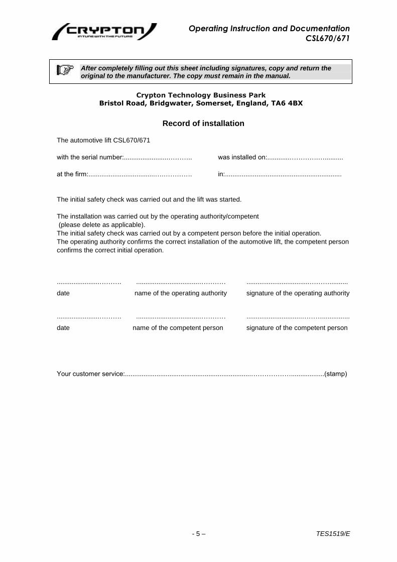
After completely filling out this sheet including signatures, copy and return the original to the manufacturer. The copy must remain in the manual.
Crypton Technology Business Park Bristol Road, Bridgwater, Somerset, England, TA6 4BX
Record of installation
The automotive lift CSL670/671
with the serial number:........................……….. was installed on:............………….…..........
at the firm:....................................….…………. in:...............................................................
The initial safety check was carried out and the lift was started.
The installation was carried out by the operating authority/competent
(please delete as applicable).
The initial safety check was carried out by a competent person before the initial operation.
The operating authority confirms the correct installation of the automotive lift, the competent person
confirms the correct initial operation.
.......................………. ..................................………… ..................................………..........
date name of the operating authority signature of the operating authority
.......................………. ..................................………… ..............................………...............
date name of the competent person signature of the competent person
Your customer service:....................................................................………………..................(stamp)

Operating Instruction and Documentation
CSL670/671
- 6 – TES1519/E
Record of Handover
The automotive lift CLS670/671
with the serial number:...................................... was installed on:.......…………………….......................
at the firm:........................................….………. in:.................................……………................….........
the initial safety check was carried out and the lift was started.
The persons below were introduced after the installation of the automotive lift. The introduction was
carried out by either the installer from the lift-manufacturer or from a franchised dealer (competent
person).
............................................ ......................................... ............................................ date name signature
............................................ ......................................... ............................................ date name signature
............................................ ......................................... ............................................ date name signature
............................................ ......................................... ............................................ date name signature
............................................ ......................................... ............................................ date name signature
............................................ ......................................... ............................................ date name signature ............................................ ......................................... ............................................ date name signature ............................................ ......................................... ............................................ date name signature ............................................ ......................................... ............................................ date name signature ............................................ ......................................... ............................................ date name signature
Your customer service:...............................................................………………………........(stamp)
Operating Instruction and Documentation
CSL670/671
- 7 – TES1519/E
1. General Information
The document “Operating Instructions and Documentation” contains important information
about installation, operation and maintenance of the automotive lift.
Conformation of installation of the automotive lift is recorded on the “Record of
Installation” form and must be signed and returned to Crypton Limited.
Conformation of once off, regular and out of the ordinary service checks are recorded on
the respective check forms. The forms are used to document the checks. They should
not be removed from the manual.
All Changes to the structure and any change of location of the automotive lift must be
registered in the ”Master document” of the lift.
1.1 Installation and service checks of the automotive lift
Only specialised staff are allowed to repair and maintain the lift and only these specialised staff
are allowed to conduct safety checks on the lift. For the purposes of this document these
specialised staff will be called Experts and Competent persons.
Experts are persons (for example self-employed engineers, experts) who have received
instructions and have the appropriate experience to check and to test the automotive
lifts. They are aware of the work involved and know the accident prevention
regulations.
Competent persons are persons who have acquired adequate knowledge and experience with
automotive lifts. They have completed the appropriate training provided by the lift-
manufacturer (the servicing technicians of the manufacturer or dealer, are regarded as
competent)
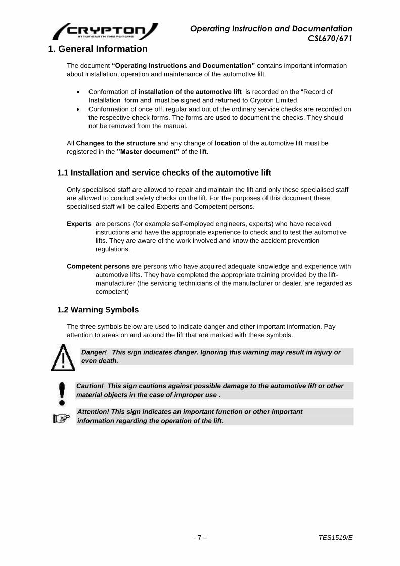
1.2 Warning Symbols
The three symbols below are used to indicate danger and other important information. Pay
attention to areas on and around the lift that are marked with these symbols.
Danger! This sign indicates danger. Ignoring this warning may result in injury or
even death.
Caution! This sign cautions against possible damage to the automotive lift or other
material objects in the case of improper use .
Attention! This sign indicates an important function or other important
information regarding the operation of the lift.

Operating Instruction and Documentation
CSL670/671
- 8 – TES1519/E
2. Master document of the automotive lift
2.1 Lift–manufacturer Crypton Crypton Technology Business Park Bristol Road Bridgwater, Somerset England TA6 4BX
2.2 Application
The automotive lift is a lifting mechanism for lifting motor vehicles with a laden weight of 5000 kg. The automotive lift also incorporates equipment for axial measurement of tyre and brake service. The automotive lift can be installed above or below the floor surface. It is not permitted to install the standard lift in hazardous locations or in wash bays. The lift is not equipped to be installed on ramped surfaces or for carrying people. Before operating the lift pay attention to the detailed operating instructions and maintenance instructions. The lift is equipped with a play detector which is able to detect play in the axles and on single wheel suspensions. The detection is possible up to a load of 1300 kg per wheel.
2.3 Changes to the Lift Construction Changes to the construction, expert checking, resumption of work (date, type of change, signature of the expert) ..............................................................................................................................................................
..............................................................................................................................................................
..............................................................................................................................................................
..................................………………………………………..............………………………………………..
Name, address of the expert ..........................................……...... ....……................................................
Location, Date Signature of the expert
2.4 Re positioning of the automotive lift Re positioning of the automotive lift, expert checking, resumption of work (date, kind of change, signature of the competent) ..............................................................................................................................................................
.............................................................................................………………………………………………
……………..…………….………………………………………..…………………………………………….
…..……………………………………………………………………………………………………………….
Name, address of the competent person .............................................. ....................................................... Location, Date Signature of the competent person
Operating Instruction and Documentation
CSL670/671
- 9 – TES1519/E
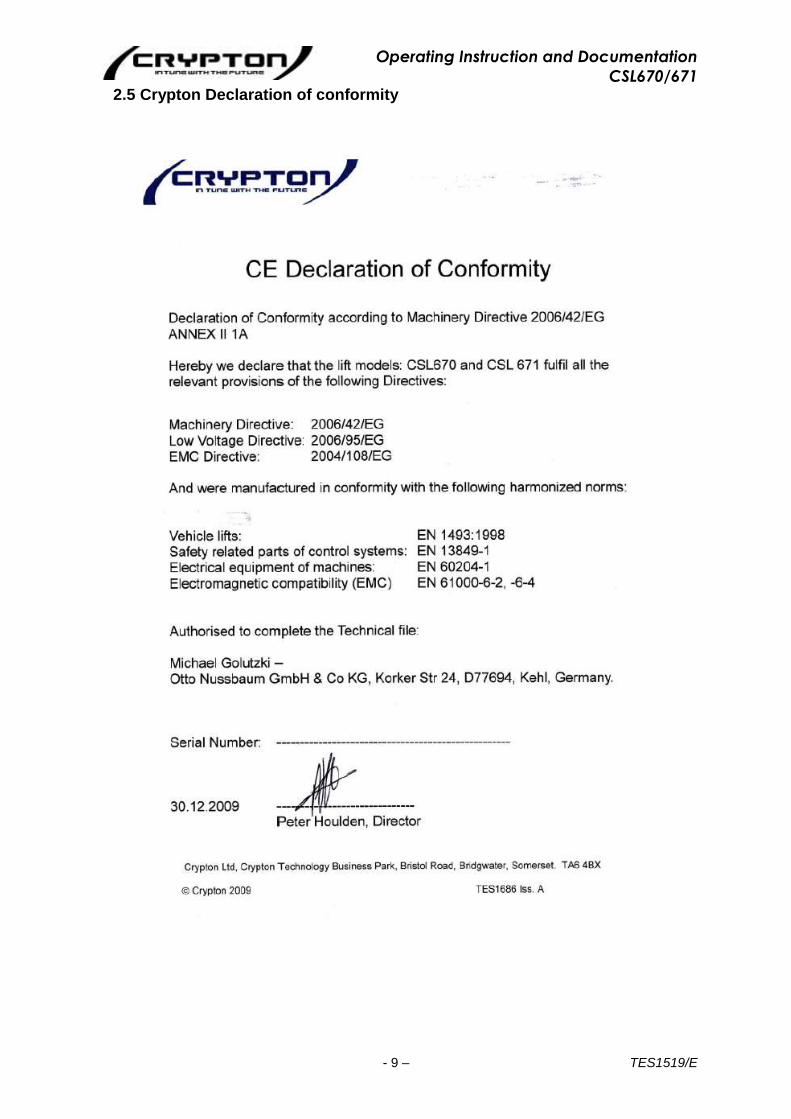
2.5 Crypton Declaration of conformity

Operating Instruction and Documentation
CSL670/671
- 10 – TES1519/E
3. Technical Information
3.1 Technical ratings
Lifting capacity 5000 kg
Load distribution max. 2:1 in or against the drive on direction
Lifting time approx. 27 sec
Lowering time approx. 32 sec
Lifting capacity play detector minimum 1300 kg per wheel
Line voltage 400 Volt three phase
Power rating 3.0 kW
Motor speed 2800 rev./min
Pump capacity 2.7 ccm (Marz.)
Hydraulic pressure approx. 300 bar
Pressure control valve approx. 320 bar
Hydraulic pressure play detector approx. 123 bar
Pressure control valve play detector approx. 125 bar
Oil tank per Hydraulic unit approx. 17 Litre
Sound level 75 dB(A)
Connection by customer 3~/N+PE, 400V, 50 Hz
fuse T16A (time-lag fuse)
observe your country regulations
Operating Instruction and Documentation
CSL670/671
- 11 – TES1519/E
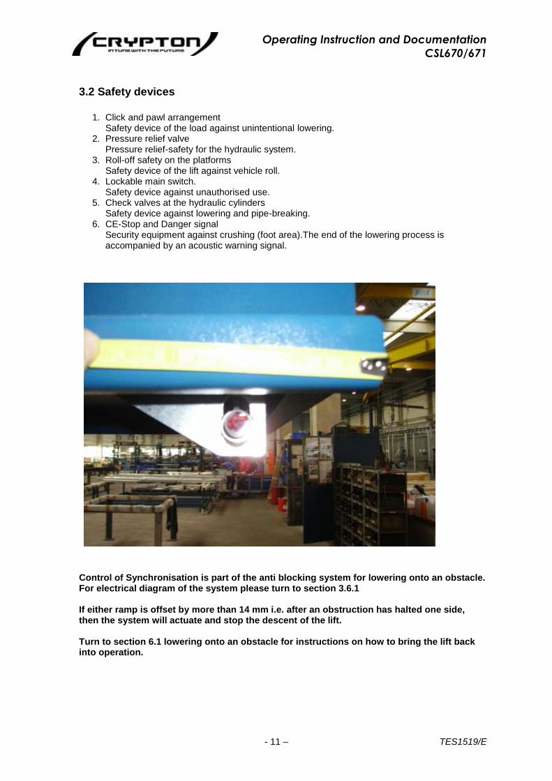
3.2 Safety devices
1. Click and pawl arrangement Safety device of the load against unintentional lowering.
2. Pressure relief valve Pressure relief-safety for the hydraulic system.
3. Roll-off safety on the platforms Safety device of the lift against vehicle roll.
4. Lockable main switch. Safety device against unauthorised use.
5. Check valves at the hydraulic cylinders Safety device against lowering and pipe-breaking.
6. CE-Stop and Danger signal Security equipment against crushing (foot area).The end of the lowering process is accompanied by an acoustic warning signal.
Control of Synchronisation is part of the anti blocking system for lowering onto an obstacle. For electrical diagram of the system please turn to section 3.6.1 If either ramp is offset by more than 14 mm i.e. after an obstruction has halted one side, then the system will actuate and stop the descent of the lift. Turn to section 6.1 lowering onto an obstacle for instructions on how to bring the lift back into operation.
Operating Instruction and Documentation
CSL670/671
- 12 – TES1519/E
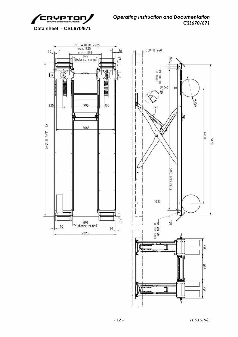
Data sheet - CSL670/671
*
Operating Instruction and Documentation
CSL670/671
- 13 – TES1519/E
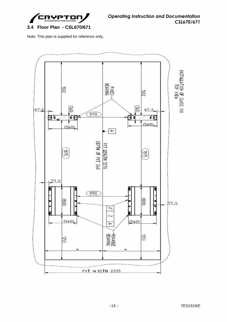
3.4 Floor Plan - CSL670/671
Note: This plan is supplied for reference only,
Operating Instruction and Documentation
CSL670/671
- 14 – TES1519/E
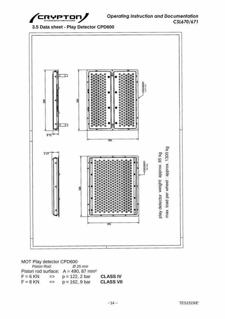
3.5 Data sheet - Play Detector CPD600
MOT Play detector CPD600 Piston Rod: Ø 25 mm
Piston rod surface: A = 490, 87 mm² F = 6 KN => p = 122, 2 bar CLASS IV
F = 8 KN => p = 162, 9 bar CLASS VII

Operating Instruction and Documentation
CSL670/671
- 15 – TES1519/E
3.6 Electrical Circuit Diagrams (Connection Diagrams) The earth connections should comply with local regulations Make sure that all connections and contacts are secure and in place Check that all wiring and electrical components are in place before commissioning Do not allow commissioning at a site not suitable for the equipment.
1. Connection diagrams and electrical components All diagrams have been drawn by us to the best of our knowledge. We take no responsibility for diagrams other than these to be used with the equipment. This is especially the case of diagrams drawn by second parties.
2. Checking the diagrams The diagrams do not always refer to serial components. Some of these components such as switches, thermostats and motors might not be shown. Even with careful testing, we cannot rule out problems occurring with the systems. We cannot take any responsibility for misuse of the guidelines on installation of the equipment. Any request for changes to the diagrams in order to enable the equipment to function better will be at the request of a surplus charge. Improvements by third parties cannot be accepted. Equipment: CSL 670/671 Diagram No. CSL 670/671
3. Safety checks and means of protection All connections have been made under the code VDEO 100/0113 and the accident prevention code V8641 for electrical equipment. The following tests have been completed:
1. Isolation check on the switchboard and control boards according to VDEO/5 73 2. Checking the functions of the applied safety features by indirect touching of components
according to the code VDEO100g/7/75 par 22. 3. Functions and component checks according to code VDE560/11 87
Other safety codes have been adhered to:
1. Protection against direct contact code VDEO100/5. 73. Par 4 2. Protection against indirect contact code VDE=100/5. 73. Par 5
These connection diagrams are the property of the manufacturers. They should not be used for any other purpose or given to a third party without the authority of the manufacturers
Next: Schematic Diagrams for CSL670/CSL671 with hydraulic Axle Play Detector.

Operating Instruction and Documentation
CSL670/671
- 16 – TES1519/E
3.6.1 Electrical Circuit Diagrams Standard Version
Operating Instruction and Documentation
CSL670/671
- 17 – TES1519/E
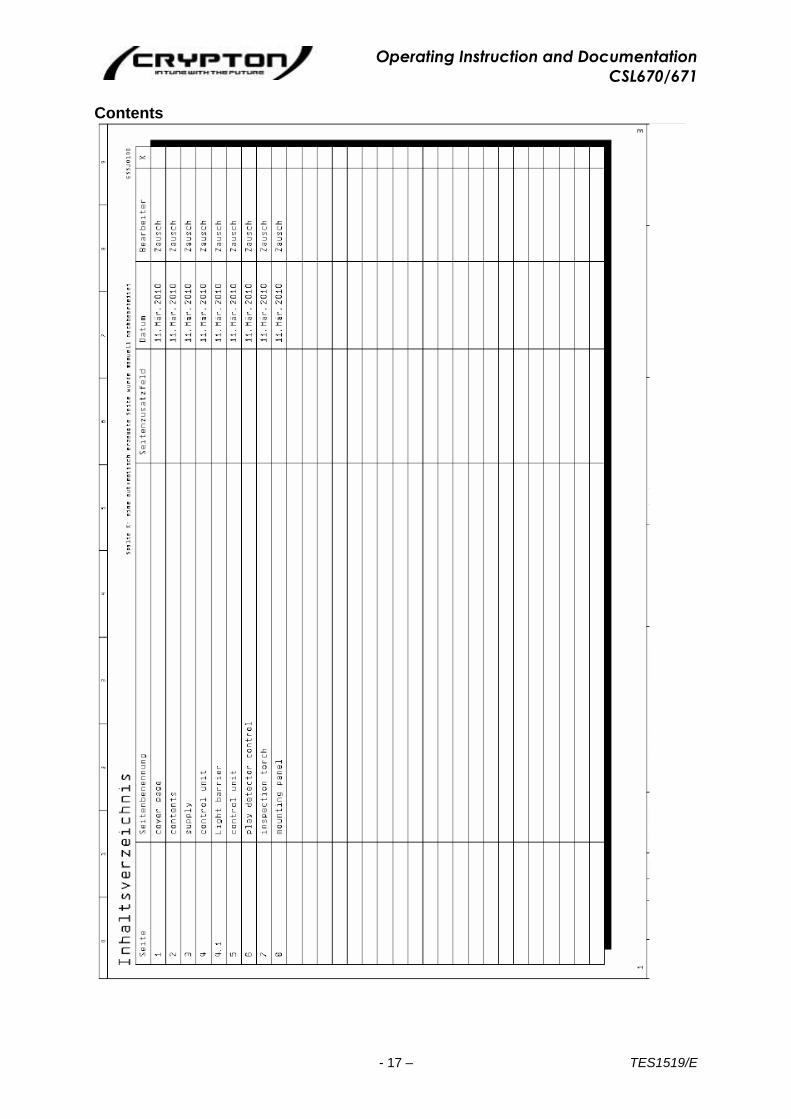
Contents
Operating Instruction and Documentation
CSL670/671
- 18 – TES1519/E
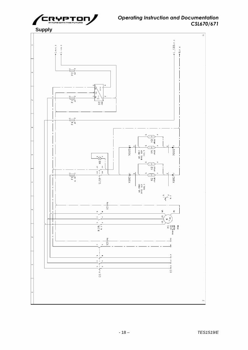
Supply
Operating Instruction and Documentation
CSL670/671
- 19 – TES1519/E
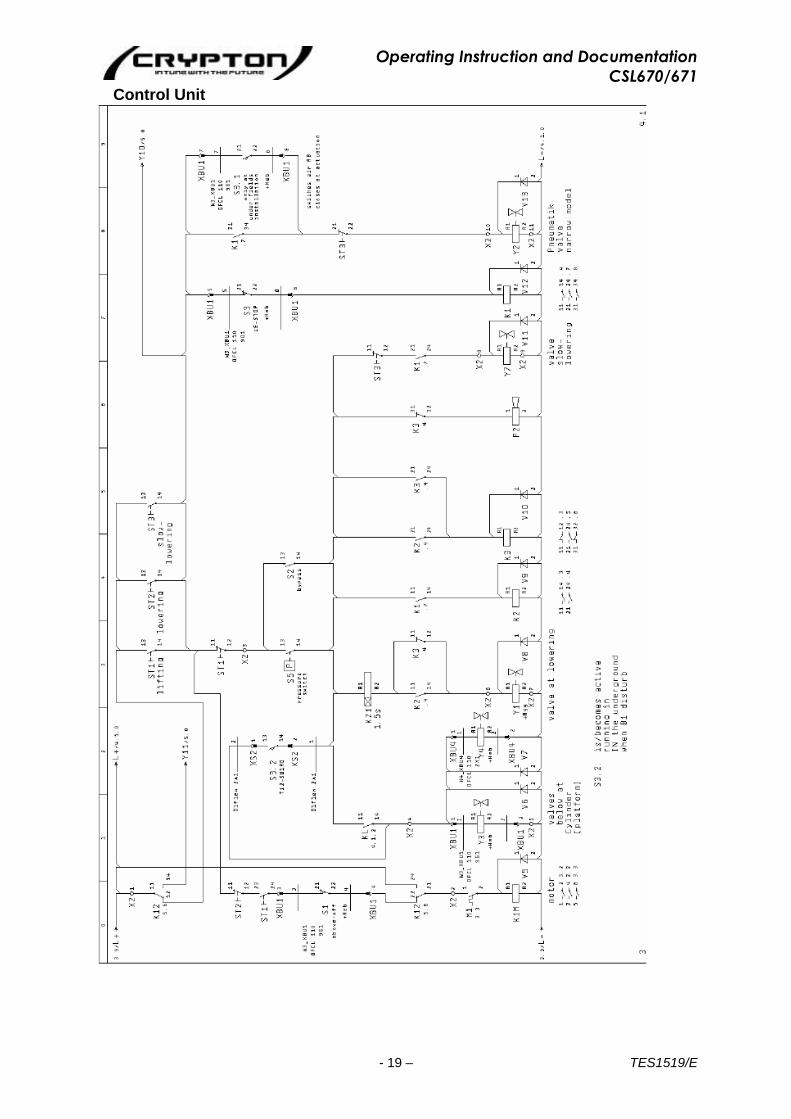
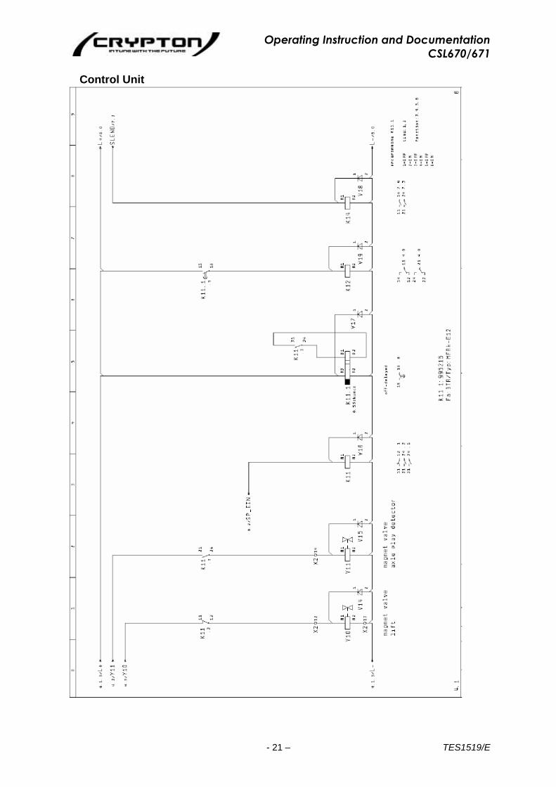
Control Unit

Operating Instruction and Documentation
CSL670/671
- 20 – TES1519/E
Light Barrier
Operating Instruction and Documentation
CSL670/671
- 21 – TES1519/E
Control Unit
Operating Instruction and Documentation
CSL670/671
- 22 – TES1519/E
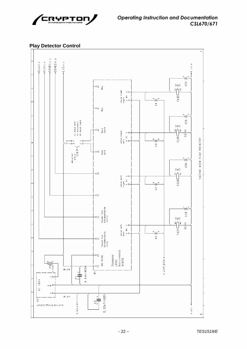
Play Detector Control

Operating Instruction and Documentation
CSL670/671
- 23 – TES1519/E
Inspection Torch
Operating Instruction and Documentation
CSL670/671
- 24 – TES1519/E
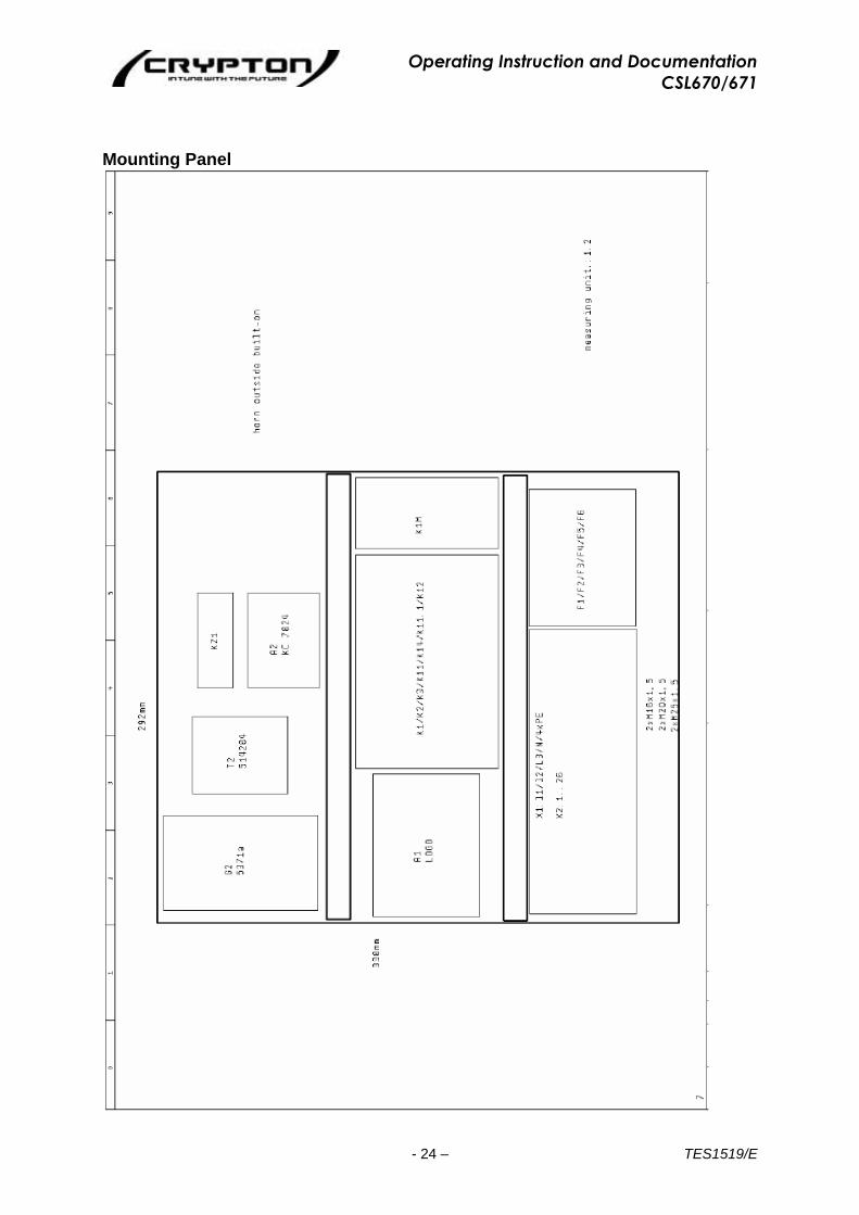
Mounting Panel
Operating Instruction and Documentation
CSL670/671
- 25 – TES1519/E
3.6.2 Electrical Circuit Diagram – Version with wireless inspection lamp
Operating Instruction and Documentation
CSL670/671
- 26 – TES1519/E
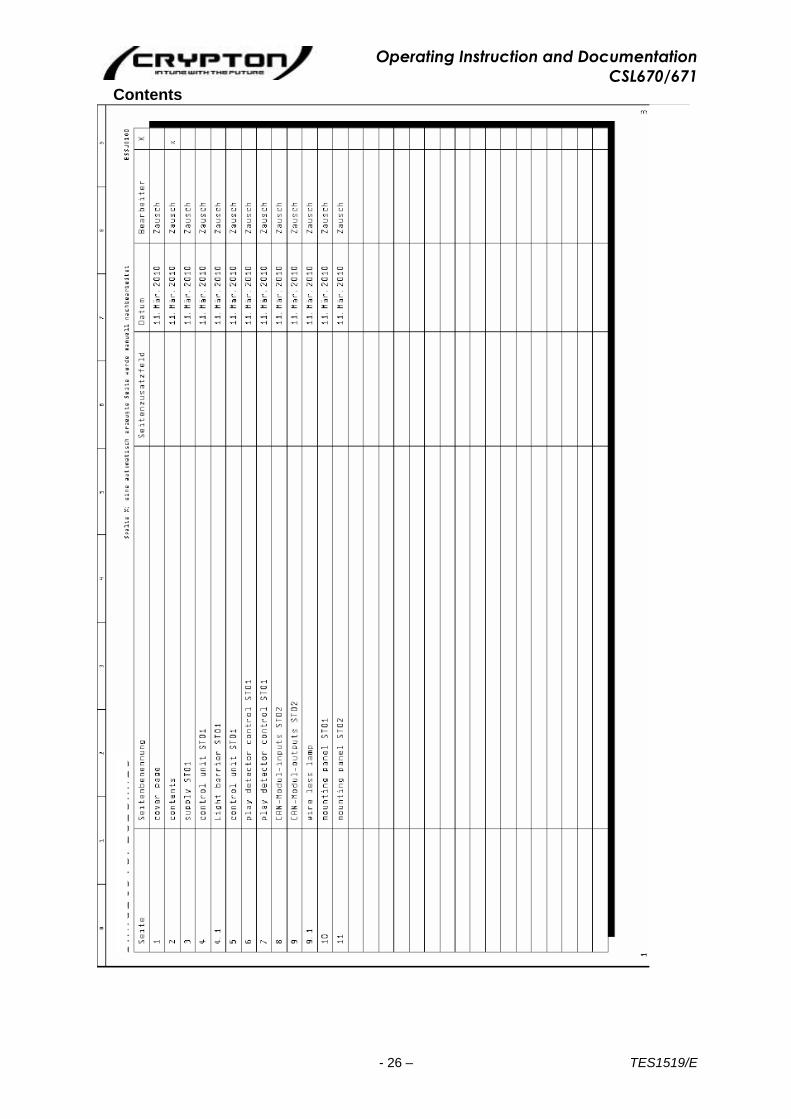
Contents

Operating Instruction and Documentation
CSL670/671
- 27 – TES1519/E
Supply ST01
Operating Instruction and Documentation
CSL670/671
- 28 – TES1519/E
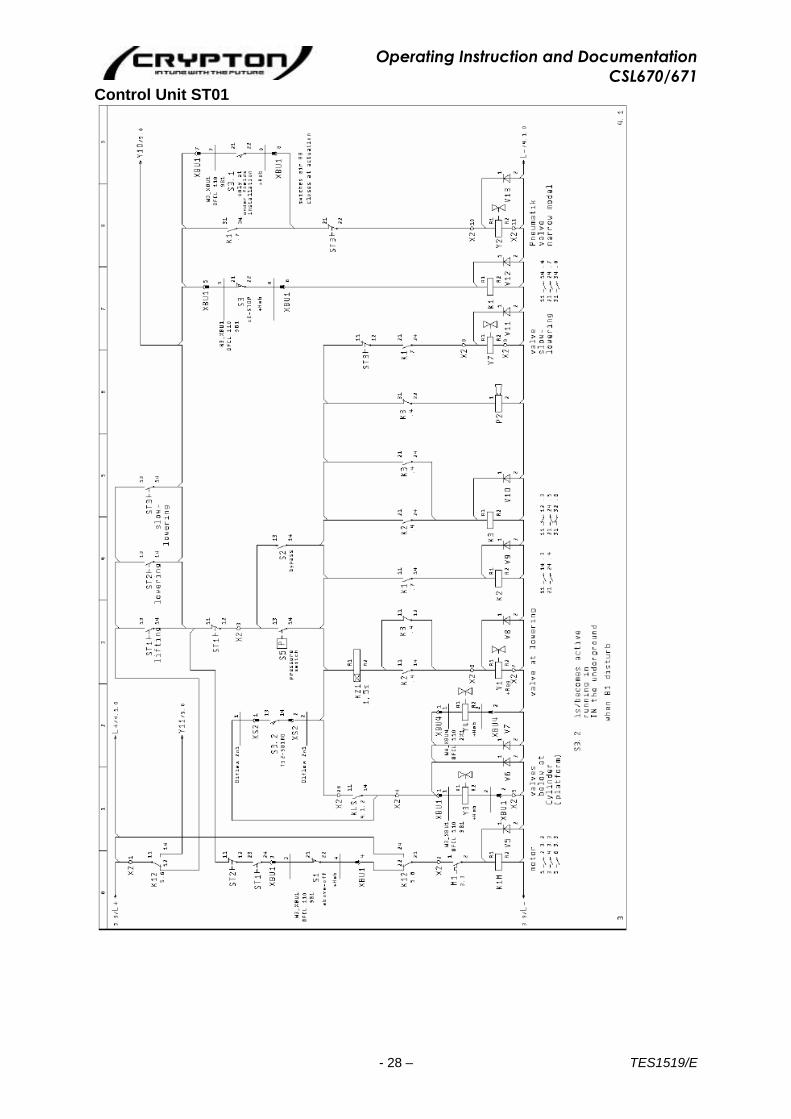
Control Unit ST01

Operating Instruction and Documentation
CSL670/671
- 29 – TES1519/E
Light Barrier ST01

Operating Instruction and Documentation
CSL670/671
- 30 – TES1519/E
Control Unit ST01
Operating Instruction and Documentation
CSL670/671
- 31 – TES1519/E
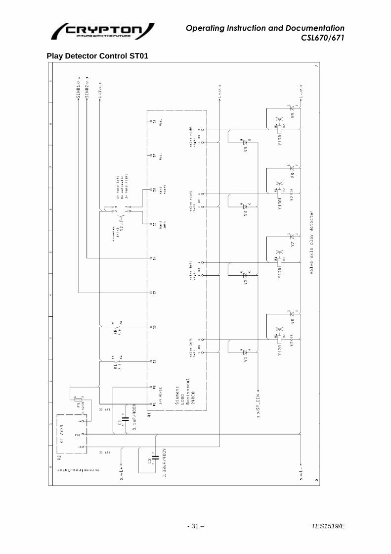
Play Detector Control ST01
Operating Instruction and Documentation
CSL670/671
- 32 – TES1519/E
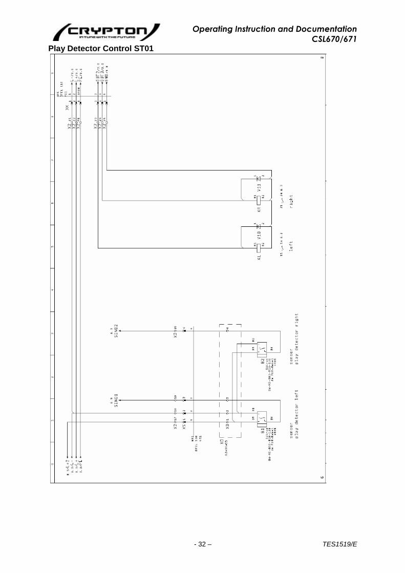
Play Detector Control ST01
Operating Instruction and Documentation
CSL670/671
- 33 – TES1519/E
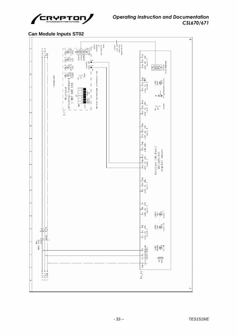
Can Module Inputs ST02
Operating Instruction and Documentation
CSL670/671
- 34 – TES1519/E
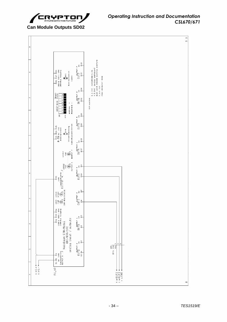
Can Module Outputs SD02
Operating Instruction and Documentation
CSL670/671
- 35 – TES1519/E
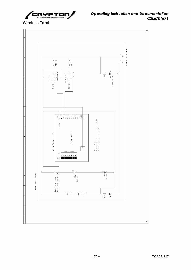
Wireless Torch

Operating Instruction and Documentation
CSL670/671
- 36 – TES1519/E
Mounting Panel ST01

Operating Instruction and Documentation
CSL670/671
- 37 – TES1519/E
Mounting Panel ST02
Operating Instruction and Documentation
CSL670/671
- 38 – TES1519/E
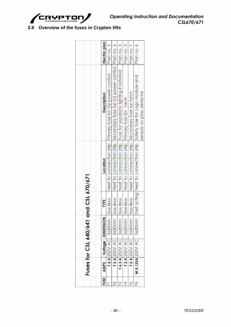
3.9 Overview of the fuses in Crypton lifts

Operating Instruction and Documentation
CSL670/671
- 39 – TES1519/E
3.10 Hydraulic Diagram
Operating Instruction and Documentation
CSL670/671
- 40 – TES1519/E
3.10.1 Hydraulic parts list
Pos. Description order no.:
0.1 oil tank 0.2 motor 400 V; 50 Hz 990303 0.3 gear pump 2.7cm³/revolution 980282 0.4 oil filter 980201 0.5 oil level gauge 980098 0.6 hydraulic block complete 232POW22037 0.7a electrical controlled holding valve 980478 0.7b valve (deposit in the ratchet) 980478 0.7c safety valve on the lift 980478 0.7d safety valve on the lift 980478 0.8 holding valve 980480 0.9 2-way-flow- control valve 980481 0.10 pressure relief valve 232NSTL02084 0.11 emergency lowering 030ULN02064 0.13 2/2-way valve double (ball valve) - equalisation of the two rails manually 980513 0.14 bypass valve complete 0.16 screen (mounted in T-piece) 0.18 safety hydraulic block complete 030ULN02061 0.20 pressure switch”automotive lift slave side, without pressure” DSH000/003 1.0 cylinder master side 040ULN22001 2.0 cylinder slave side 040ULN22037 3.0 cylinder play detector V7 double seat valve 158641 V9 double seat valve 158641 V11 Way valve 117640 V12 Way valve 117640 DB2 pressure relief valve 155211
Operating Instruction and Documentation
CSL670/671
- 41 – TES1519/E
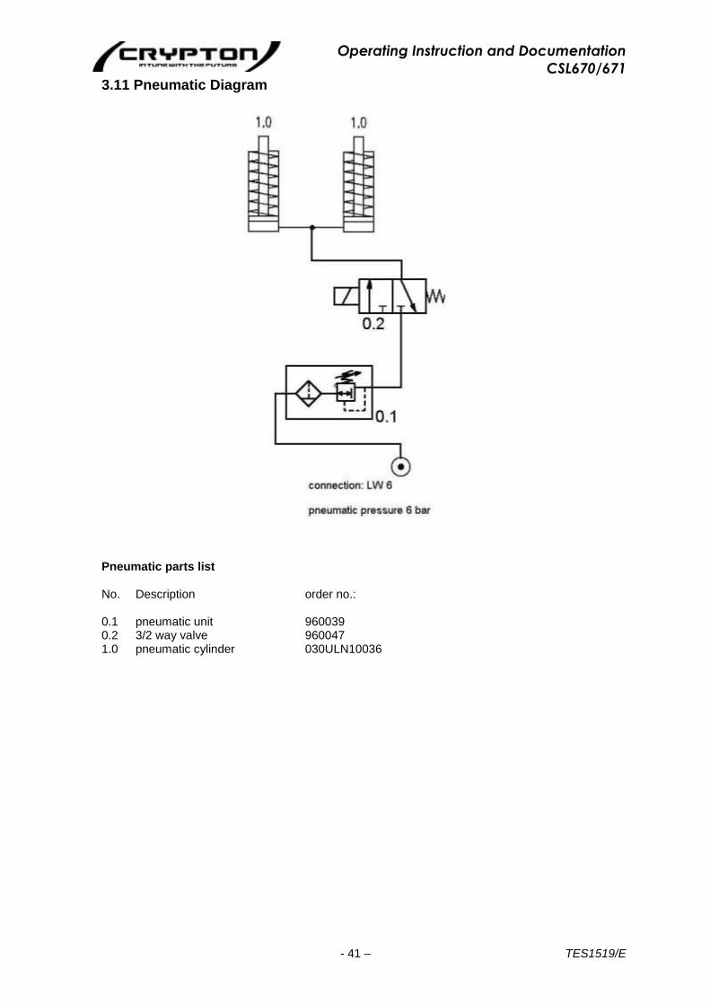
3.11 Pneumatic Diagram
Pneumatic parts list No. Description order no.: 0.1 pneumatic unit 960039 0.2 3/2 way valve 960047
1.0 pneumatic cylinder 030ULN10036

Operating Instruction and Documentation
CSL670/671
- 42 – TES1519/E
4. Safety regulations
If you use the automotive lift, the following European regulations are to be considered: BGG945: Examine of automotive-lifts; BGR500 Using automotive-lifts; (VBG14).
4.1 General safety-regulations
When using your garage equipment, basic safety precautions should always be followed, including the following:
Important Safety Instructions
1. Read all instructions 2. Care must be taken as burns can occur from touching hot parts. 3. Do not operate equipment with a damaged cord or main switch – until it has been examined
and repaired by qualified service personnel. 4. Always isolate equipment from electrical outlets when not in use. 5. To reduce the risk of fire, do not operate equipment in the vicinity of open containers of
flammable liquids (gasoline). 6. Adequate ventilation should be provided when working on operating internal combustion
engines. 7. Keep hair, loose clothing, fingers and all parts of the body away from moving parts. 8. To reduce the risk of electric shock, do not use on wet surfaces or expose to rain. 9. Use only as described in this manual. Use only manufacturer’s recommended Crypton
replacements. SAVE THESE INSTRUCTIONS
4.2 Additional safety-regulations
Especially the following regulations are very important:
• The laden weight of the lifted vehicle must not exceed 5000kg.
The maximum load distribution is 2:1 in or against the drive-on direction.
• The automotive lift must be in its lowest position, before the vehicle can be driven onto or
off the lift and can only be driven onto or off the lift from the drive on side.
• While working with the lift the operating instructions must be followed.
• Any vehicles with low clearance or vehicles with optional equipment should be pre tested to
ensure that they clear the lift ramp to avoid damage.
• Only trained personnel over the age of 18 years old are to operate this lift.
• No one is to stand within the working area (danger area) during lifting and lowering
• No one is to be raised or lowed either directly or in a vehicle by the automotive lift.
• No one is to climb onto the automotive lift or onto an already raised vehicle.
• Position the lifting pads as described by the vehicle manufacturer under the vehicle.
• Check the centre of gravity of the vehicle if heavy parts (e.g. the motor) are to be removed. • If heavy parts must be removed (e.g. motor) the centre of gravity will change. Secure the
vehicle before removing parts to avoid the possibility of the vehicle becoming insecure.
• The automotive lift must be checked by an expert after changes in construction or after
repairing carrying pads.
• The main switch must be switched off and locked before work on the vehicle can
commence. This is a safety precaution to ensure that the lift does not move during work.
• .....The main switch must be switched off and locked before any maintenance or repair work on the automotive lift itself can be carried out.
• During lifting or lowering, the operator must observe the vehicle to ensure that the vehicle
and the lift are functioning correctly.
Operating Instruction and Documentation
CSL670/671
- 43 – TES1519/E
• Installation of the standard-mobile column lift in hazardous or dangerous locations such as washing bays is dangerous and is not allowed.
• During lifting or lowering the vehicle it must be observed by the operator.
5. Operating Instructions
The Safety Regulations must be observed and adhered to while working with the automotive lift. Read the safety regulations in chapter 4 carefully before working with the lift!
5.1 Lifting the vehicle
• Drive vehicle onto the centre of the lift in the longitudinal and transverse directions.
Each wheel must rest completely on its respective platform. Failure to correctly position the vehicle may result in the vehicle falling from the lift.
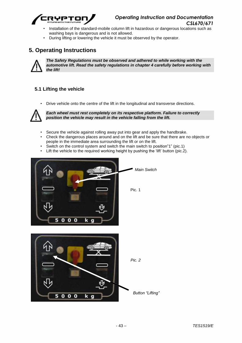
• Secure the vehicle against rolling away put into gear and apply the handbrake. • Check the dangerous places around and on the lift and be sure that there are no objects or
people in the immediate area surrounding the lift or on the lift. • Switch on the control system and switch the main switch to position”1” (pic.1) • Lift the vehicle to the required working height by pushing the ‘lift’ button (pic.2).
Main Switch
Pic. 1
Pic. 2
Button “Lifting”
Operating Instruction and Documentation
CSL670/671
- 44 – TES1519/E
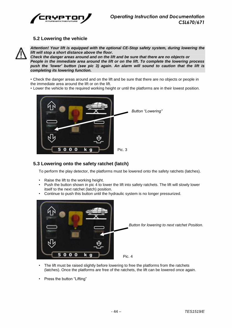
5.2 Lowering the vehicle
Attention! Your lift is equipped with the optional CE-Stop safety system, during lowering the lift will stop a short distance above the floor. Check the danger areas around and on the lift and be sure that there are no objects or People in the immediate area around the lift or on the lift. To complete the lowering process push the ‘lower’ button (see pic 3) again. An alarm will sound to caution that the lift is completing its lowering function.
• Check the danger areas around and on the lift and be sure that there are no objects or people in the immediate area around the lift or on the lift. • Lower the vehicle to the required working height or until the platforms are in their lowest position.
Button “Lowering”
Pic. 3
5.3 Lowering onto the safety ratchet (latch)
To perform the play detector, the platforms must be lowered onto the safety ratchets (latches). • Raise the lift to the working height. • Push the button shown in pic 4 to lower the lift into safety ratchets. The lift will slowly lower
itself to the next ratchet (latch) position. • Continue to push this button until the hydraulic system is no longer pressurized.
Button for lowering to next ratchet Position.
Pic. 4
• The lift must be raised slightly before lowering to free the platforms from the ratchets
(latches). Once the platforms are free of the ratchets, the lift can be lowered once again. • Press the button “Lifting”
Operating Instruction and Documentation
CSL670/671
- 45 – TES1519/E
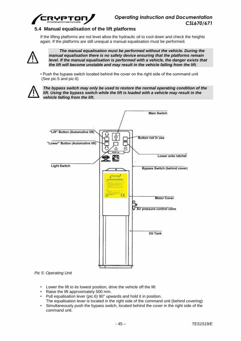
5.4 Manual equalisation of the lift platforms
If the lifting platforms are not level allow the hydraulic oil to cool down and check the heights again. If the platforms are still unequal a manual equalisation must be performed.
The manual equalisation must be performed without the vehicle. During the
manual equalisation there is no safety device ensuring that the platforms remain level. If the manual equalisation is performed with a vehicle, the danger exists that the lift will become unstable and may result in the vehicle falling from the lift.
• Push the bypass switch located behind the cover on the right side of the command unit (See pic.5 and pic.6)
The bypass switch may only be used to restore the normal operating condition of the lift. Using the bypass switch while the lift is loaded with a vehicle may result in the vehicle falling from the lift.
Pic 5: Operating Unit
• Lower the lift to its lowest position, drive the vehicle off the lift • Raise the lift approximately 500 mm. • Pull equalisation lever (pic.6) 90° upwards and hold it in position.
The equalisation lever is located in the right side of the command unit (behind covering) • Simultaneously push the bypass switch, located behind the cover in the right side of the
command unit.
5000 kg

Operating Instruction and Documentation
CSL670/671
- 46 – TES1519/E
• While pulling the equalisation lever and pressing the bypass switch, Press either the ”Up” or ”Down” buttons to adjust the height until the height of the two platforms are equal.
• Once the platforms are equal in height, release the equalisation lever (It will return automatically) and close the covering.
Pic 6: Equalisation Lever
5.5 Play detector
Warning ! Only operate the Play Detector when the lift has been lowered into its Safety latch position
Application
The Play detector is a tool for the recognition of slackness in the ball and socket joints of vehicles. The operating unit is equipped with a lamp. The testing vehicle-parts can become illuminated under the vehicle.
The axle play detector should be operated and used in accordance with the MOT testing procedure which can be found in the relevant up to date testers manual. a. By pressing the top button the cycle of the left plate will activate. After activation release the
button and check the ball joints and steering components according to the MOT procedures. b. By pressing the lower button the cycle of the right plate will activate. After activation release
the button and check the ball joints and steering components according to the MOT procedures.
• After checking, put the operating unit into the holding device. The lamp will go off.
Pic.7 Press the button to start the cycles with the left play detector. Cycle: centre => left => right => centre
Pic.8 Press the button to start the cycles with the left right play detector. Cycle: centre => left => right => centre

Operating Instruction and Documentation
CSL670/671
- 47 – TES1519/E
5.6 Function test before first initiation
• Before working with the play detector, carry out a functionality test. • Behind the operating unit is a additional switch with three positions. • Remove the rear upper the cover of the operating unit.
Test the function of the individual play detector plates. Pos. “0” - This is the Position for the normal function Pos. “1” - Plate 1 of the play detector is individually moveable.
Press the button of the hand lamp. The plate starts the cycle until the button is pressed again
Pos. “2” - Plate 2 of the play detector is individually moveable. Press the button of the hand lamp. The plate starts the cycle until the button is pressed again.
• After testing, set the switch on Position “0”.
6. Troubleshooting
If the lift is not working properly, the reason might be quite simple. Please check the lift for the potential reasons mentioned on the following pages. If the cause of trouble cannot be found, please call the technical service on 0844 665 7610
Repairs to the lift’s safety devices as well as repairs and examinations of the electrical fittings may only be performed by specialists.
Problem: Motor does not start!
Potential causes:
No power supply
Main switch is not engaged
The main switch is defective
Fuse defective
The feed line is cut
Thermal switch in the motor is active
Motor is defective
solution:
Check the power supply
Check the main switch
Check the main switch
Check Fuse
Check the complete cable
Let motor cool down
Call technical service
Operating Instruction and Documentation
CSL670/671
- 48 – TES1519/E
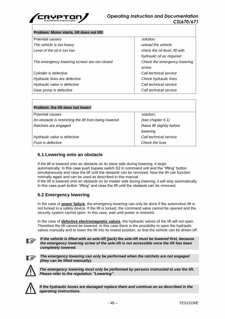
Problem: Motor starts, lift does not lift!
Potential causes:
The vehicle is too heavy
Level of the oil is too low
The emergency lowering screws are not closed
Cylinder is defective
Hydraulic lines are defective
Hydraulic valve is defective
Gear pump is defective
solution:
unload the vehicle
check the oil level, fill with
hydraulic oil as required
Check the emergency lowering
screw
Call technical service
Check hydraulic lines
Call technical service
Call technical service
Problem: the lift does not lower!
Potential causes:
An obstacle is restricting the lift from being lowered
Ratchets are engaged
Hydraulic valve is defective
Fuse is defective
solution:
(see chapter 6.1)
Raise lift slightly before
lowering
Call technical service
Check the fuse
6.1 Lowering onto an obstacle If the lift is lowered onto an obstacle on its slave side during lowering, it stops automatically. In this case push bypass switch S2 in command unit and the “lifting” button simultaneously and raise the lift until the obstacle can be removed. Now the lift can function normally again and can be used as described in this manual. If the lift is lowered onto an obstacle on its master side during lowering, it will stop automatically. In this case push button ”lifting” and raise the lift until the obstacle can be removed.
6.2 Emergency lowering
In the case of power failure, the emergency-lowering can only be done if the automotive-lift is not locked in a safety device. If the lift is locked, the command valve cannot be opened and the security system cannot open. In this case, wait until power is restored. In the case of defective electromagnetic valves, the hydraulic valves of the lift will not open. Therefore the lift cannot be lowered. In this case there is the possibility to open the hydraulic valves manually and to lower the lift into its lowest position, so that the vehicle can be driven off.
If the vehicle is lifted with an axle-lift (jack) the axle-lift must be lowered first, because the emergency lowering screw of the axle-lift is not accessible once the lift has been completely lowered.
The emergency lowering can only be performed when the ratchets are not engaged (they can be lifted manually). The emergency lowering must only be performed by persons instructed to use the lift. Please refer to the regulation ”Lowering”. If the hydraulic hoses are damaged replace them and continue on as described in the operating instructions.
Operating Instruction and Documentation
CSL670/671
- 49 – TES1519/E
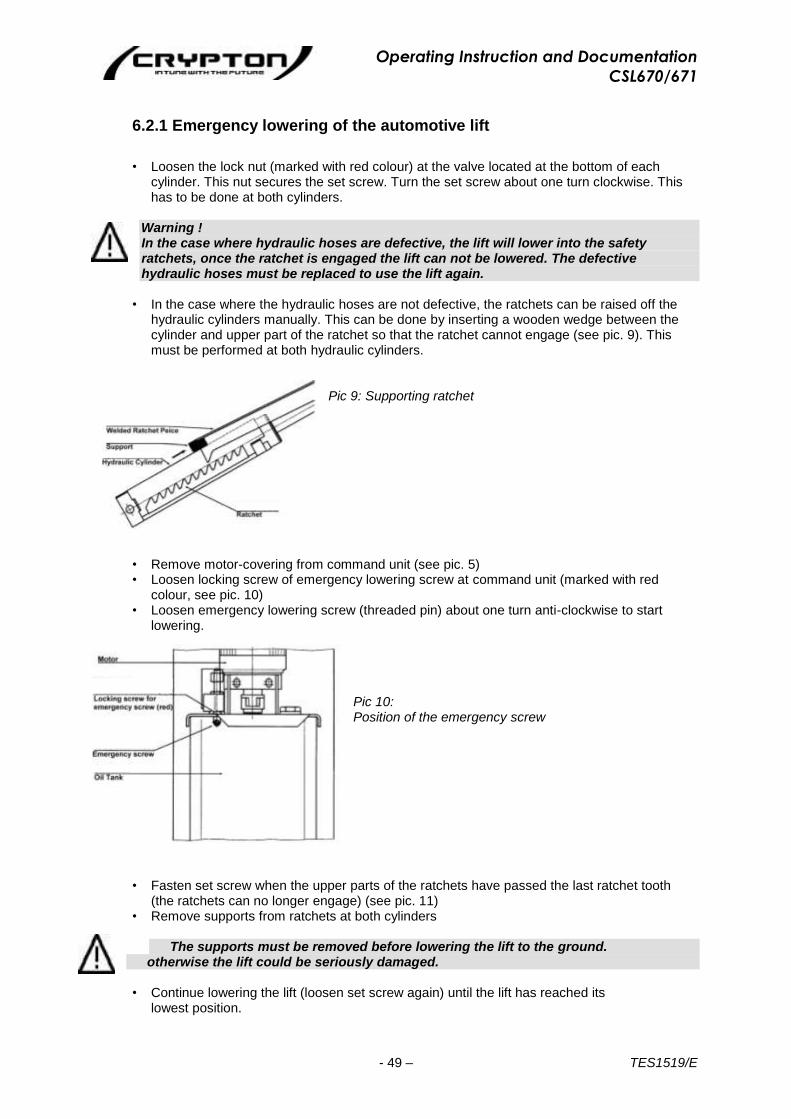
6.2.1 Emergency lowering of the automotive lift
• Loosen the lock nut (marked with red colour) at the valve located at the bottom of each
cylinder. This nut secures the set screw. Turn the set screw about one turn clockwise. This has to be done at both cylinders.
Warning ! In the case where hydraulic hoses are defective, the lift will lower into the safety ratchets, once the ratchet is engaged the lift can not be lowered. The defective hydraulic hoses must be replaced to use the lift again.
• In the case where the hydraulic hoses are not defective, the ratchets can be raised off the
hydraulic cylinders manually. This can be done by inserting a wooden wedge between the cylinder and upper part of the ratchet so that the ratchet cannot engage (see pic. 9). This must be performed at both hydraulic cylinders.
Pic 9: Supporting ratchet
• Remove motor-covering from command unit (see pic. 5) • Loosen locking screw of emergency lowering screw at command unit (marked with red
colour, see pic. 10) • Loosen emergency lowering screw (threaded pin) about one turn anti-clockwise to start
lowering. Pic 10: Position of the emergency screw
• Fasten set screw when the upper parts of the ratchets have passed the last ratchet tooth
(the ratchets can no longer engage) (see pic. 11) • Remove supports from ratchets at both cylinders
The supports must be removed before lowering the lift to the ground.
otherwise the lift could be seriously damaged.
• Continue lowering the lift (loosen set screw again) until the lift has reached its lowest position.

Operating Instruction and Documentation
CSL670/671
- 50 – TES1519/E
Pic 11: Removing support
• Fasten the set screw and secure it by fastening the locking screw. • Turn out thread pins at both stop valves of the bottom of hydraulic cylinders. Secure them
with the red security nuts.
After finishing the emergency lowering, all the set screws must be adjusted back to their original positions. Otherwise a malfunction may occur. • Reinstall covering plates of both stop valves in the drive-on areas of the platforms. • Drive vehicle off the lift • Shut down the lift until the defective pieces or valves have been replaced
7. Inspection and Maintenance
Before conducting maintenance work, preparations must be made to ensure that during maintenance and repair work there is no risk to the safety of people working on
or around the lift, and also that there is no risk of damage to equipment being used on or around the lift.
To guarantee the utmost availability and to ensure that the lift remains functional, maintenance work contracts are organised between our clients and their local retailers. A service must be performed at regular intervals of 12 months through the operator in accordance with following service manual. If the lift is in continuous operation or in a dirty environment, the maintenance rate must be increased. During daily operation the lift must be closely observed to ensure that it is functioning correctly. In the case of malfunction or leakage the technical service must be informed 0845 634 9904
7.1 Maintenance schedule for the lift
• Before beginning any maintenance work isolate the power supply. Secure the main switch (lock it). Secure the danger area around the automotive lift and secure the lift against unintentional lowering.
• Clean the piston-rod using compressed air.
Grease the piston rods with multipurpose oil.
Clean and check the stripper of the guidance-piston.
• Grease the lubricate nipples with a multipurpose lipid. (Example: Auto Top 2000 LTD.
Agape)
• Clean and lubricate the moving parts of the lift (hinge bolts, sliding pieces, and sliding
surfaces) grease with a multipurpose lipid (example: Auto Top 2000 LTD. Agape).
• Check the hydraulic tubes for leakage.
Life time of the hydraulic hoses.
The use duration of the hose lines should not exceed six years, including a storage time of at
the most, two years.
Deviating of the use duration, according to available inspection results and empirical values
with consideration of the operating conditions, can be specified in individual cases (excerpt
from standard: ZH 1/74// DIN 20066).
• Remove all fluids in the canister. After it, seal the cover again.
Operating Instruction and Documentation
CSL670/671
- 51 – TES1519/E
• Check the oil level. Fill the tank with clean, high quality oil (32 cst) (e.g. HLP 32 LTD. OEST
Company)
• The hydraulic oil has to be changed at least once a year. To change the oil, lower the lift into
its lowest position. Empty all tanks and refill with clean oil, see chapter 3.1.
Use an ATF-Suffix hydraulic-oil (OEST Company) if the ambient temperature is less than 5
degrees centigrade. After filling, the hydraulic oil must be between the upper and lower
markings of the oil level gauge.
Remove and dispose of the old oil in accordance with the appropriate regulations.
• Check all welded joints for cracks on the automotive-lift.
If any cracks are found on the lift cease use immediately. Switch-off and secure the
main switch (lock) and call your service agent.
• Check the condition and the function of the safety ratchet.
• Check all surfaces and repair if necessary.
• Damage to external surfaces, must be immediately repaired.
If theses repairs are not made immediately, permanent damage to the powder-coated
surface may result.
Repair and clean damaged areas with an abrasive paper (grain 120). After this is complete,
use a suitable paint (observe the RAL Number).
• Check the zinc surface and repair it with a suitable tool. Use abrasive paper (grain 280).
White rust can result from moisture lying in certain areas for long periods of time. Poor
aerating can also result in rust formation.
Rust may result from mechanical damage, wear, aggressive sediments (de-icing salt, liquids)
or insufficient cleaning.
Repair and clean these areas with abrasive paper (grain 280).
After this is complete, use a suitable paint (observe the RAL Number).
• Check all the safety devices of the lift (ratchet, the optional CE-Stop, etc.)
• Check the electric cable and channels for Damage.
• Check all the covers for Damage.
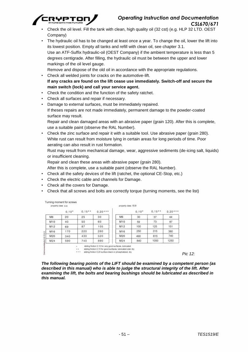
• Check that all screws and bolts are correctly torque (turning moments, see the list)
Pic 12:
The following bearing points of the LIFT should be examined by a competent person (as described in this manual) who is able to judge the structural integrity of the lift. After examining the lift, the bolts and bearing bushings should be lubricated as described in this manual.
Operating Instruction and Documentation
CSL670/671
- 52 – TES1519/E
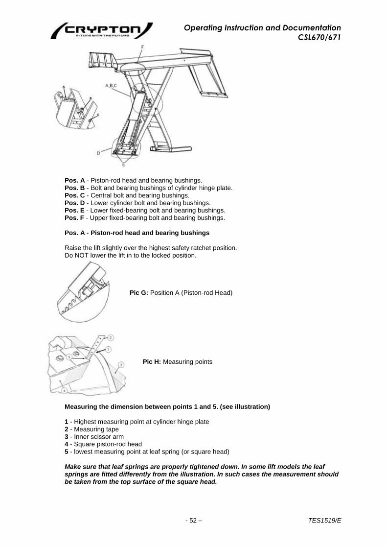
Pos. A - Piston-rod head and bearing bushings. Pos. B - Bolt and bearing bushings of cylinder hinge plate. Pos. C - Central bolt and bearing bushings. Pos. D - Lower cylinder bolt and bearing bushings. Pos. E - Lower fixed-bearing bolt and bearing bushings. Pos. F - Upper fixed-bearing bolt and bearing bushings.
Pos. A - Piston-rod head and bearing bushings
Raise the lift slightly over the highest safety ratchet position. Do NOT lower the lift in to the locked position.
Pic G: Position A (Piston-rod Head)
Pic H: Measuring points
Measuring the dimension between points 1 and 5. (see illustration)
1 - Highest measuring point at cylinder hinge plate 2 - Measuring tape 3 - Inner scissor arm 4 - Square piston-rod head 5 - lowest measuring point at leaf spring (or square head)
Make sure that leaf springs are properly tightened down. In some lift models the leaf springs are fitted differently from the illustration. In such cases the measurement should be taken from the top surface of the square head.
Pic F: Maintenance points

Operating Instruction and Documentation
CSL670/671
- 53 – TES1519/E
Check the following dimension:
The original dimension (lift in as new condition) between leaf spring and the highest point of the cylinder hinge plate is:
Model CSL670/CSL671: Original dimension: 7, 5 ± 2mm
In case the measurement is taken directly from the square head, add 2mm to the measured dimension to obtain the original dimension of the lift in as new condition.
Pos. B - Bolt and bearing bushings of cylinder hinge plate
• Remove cover • Clean area. Visually examine condition of bolt and bushings for wear. Do NOT move or
remove bolt. • Both scissors need to be examined. • Repair or re-install back to original condition. Grease/oil as described in the lubrication instructions. Pos. C - Central bolt and bearing bushings
• Remove castle-nut and split-pin • Clean area. Visually examine the condition of bolt and bushings for wear. Do NOT move or
remove bolt. • Both scissors need to be examined • Repair or re-install back to original condition. Grease/oil as described in the lubrication instructions. Pos. D - Lower cylinder bolt and bearing bushings
• The condition of the bolt and bushings need to be visually examined for wear. • The platforms of the lift need to be lowered on to an adequate support, so that the cylinder is
unloaded. Be careful not to damage the safety ledge! • Remove the split-pin from the bolt. • Slide the bolt only so far until the bearing surface of the bushing can be examined. • Both scissors need to be examined.
Operating Instruction and Documentation
CSL670/671
- 54 – TES1519/E
• Repair or re-install back to original condition. Grease/oil as described in the lubrication instructions.
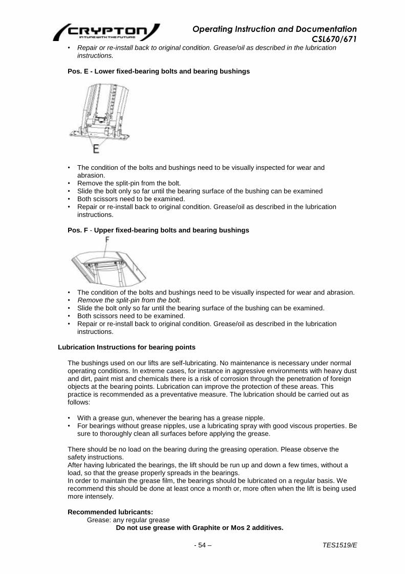
Pos. E - Lower fixed-bearing bolts and bearing bushings
• The condition of the bolts and bushings need to be visually inspected for wear and abrasion.
• Remove the split-pin from the bolt. • Slide the bolt only so far until the bearing surface of the bushing can be examined • Both scissors need to be examined. • Repair or re-install back to original condition. Grease/oil as described in the lubrication
instructions.
Pos. F - Upper fixed-bearing bolts and bearing bushings
• The condition of the bolts and bushings need to be visually inspected for wear and abrasion. • Remove the split-pin from the bolt. • Slide the bolt only so far until the bearing surface of the bushing can be examined. • Both scissors need to be examined. • Repair or re-install back to original condition. Grease/oil as described in the lubrication
instructions.
Lubrication Instructions for bearing points The bushings used on our lifts are self-lubricating. No maintenance is necessary under normal operating conditions. In extreme cases, for instance in aggressive environments with heavy dust and dirt, paint mist and chemicals there is a risk of corrosion through the penetration of foreign objects at the bearing points. Lubrication can improve the protection of these areas. This practice is recommended as a preventative measure. The lubrication should be carried out as follows: • With a grease gun, whenever the bearing has a grease nipple. • For bearings without grease nipples, use a lubricating spray with good viscous properties. Be
sure to thoroughly clean all surfaces before applying the grease.
There should be no load on the bearing during the greasing operation. Please observe the safety instructions. After having lubricated the bearings, the lift should be run up and down a few times, without a load, so that the grease properly spreads in the bearings. In order to maintain the grease film, the bearings should be lubricated on a regular basis. We recommend this should be done at least once a month or, more often when the lift is being used more intensely.
Recommended lubricants:
Grease: any regular grease Do not use grease with Graphite or Mos 2 additives.
Operating Instruction and Documentation
CSL670/671
- 55 – TES1519/E
Spray: any regular lubricating spray Do not use spray with a Silicon additive.
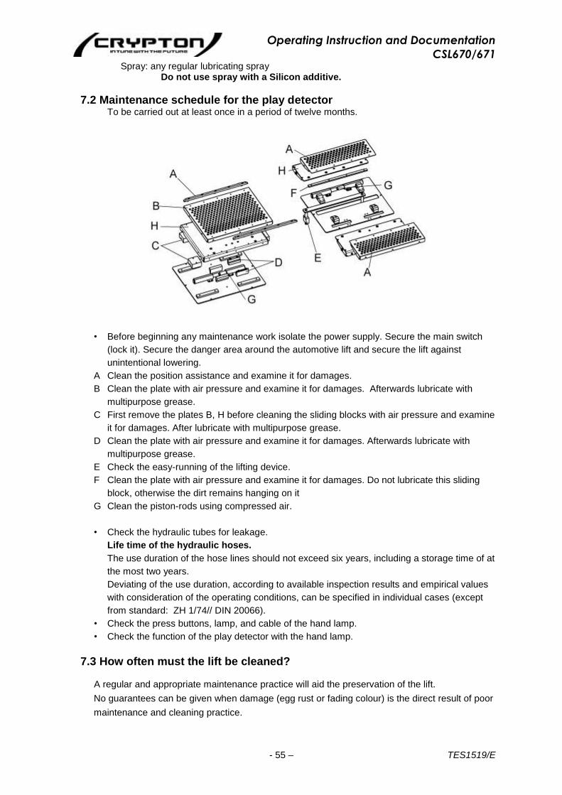
7.2 Maintenance schedule for the play detector To be carried out at least once in a period of twelve months.
• Before beginning any maintenance work isolate the power supply. Secure the main switch
(lock it). Secure the danger area around the automotive lift and secure the lift against
unintentional lowering.
A Clean the position assistance and examine it for damages.
B Clean the plate with air pressure and examine it for damages. Afterwards lubricate with
multipurpose grease.
C First remove the plates B, H before cleaning the sliding blocks with air pressure and examine
it for damages. After lubricate with multipurpose grease.
D Clean the plate with air pressure and examine it for damages. Afterwards lubricate with
multipurpose grease.
E Check the easy-running of the lifting device.
F Clean the plate with air pressure and examine it for damages. Do not lubricate this sliding
block, otherwise the dirt remains hanging on it
G Clean the piston-rods using compressed air.
• Check the hydraulic tubes for leakage.
Life time of the hydraulic hoses.
The use duration of the hose lines should not exceed six years, including a storage time of at
the most two years.
Deviating of the use duration, according to available inspection results and empirical values
with consideration of the operating conditions, can be specified in individual cases (except
from standard: ZH 1/74// DIN 20066).
• Check the press buttons, lamp, and cable of the hand lamp.
• Check the function of the play detector with the hand lamp.
7.3 How often must the lift be cleaned? A regular and appropriate maintenance practice will aid the preservation of the lift.
No guarantees can be given when damage (egg rust or fading colour) is the direct result of poor
maintenance and cleaning practice.

Operating Instruction and Documentation
CSL670/671
- 56 – TES1519/E
Regular cleaning of all kinds of dirt is the best protection against wear and the formation of rust
and will prolong the life of the lift
- Dirty deposits that can cause rust include:
• de-icing salt
• sand, pebble stone, natural soil
• all types of industrial dust
• water; also in connection with other environmental influences
• all types of aggressive deposits
• constant humidity caused by insufficient ventilation
Obviously this is dependent on the type of work being done with the lift, the degree of
cleanliness of the workshop and location of the lift. The degree and amount of dirt is dependent
on the season, on the weather conditions and the ventilation of the workshop.
During poor conditions it may be necessary to clean the lift once week, but cleaning once a
month will suffice.
Clean the lift and the floor with a non-aggressive and non-abrasive detergent. Use a gentle
detergent to clean the parts. Use standard washing-up liquid and lukewarm water.
- Do not use steam jet cleaners.
- Remove all dirt carefully with a sponge or if necessary with a brush.
- Ensure that no washing-up liquid is left on the lift after cleaning.
- Do not use aggressive means for cleaning the workshop floor and the automotive lift.
- A permanent contact with any kind of liquid is not allowed. Do not use high pressure devices
for cleaning the lift.
8. Security check
The security check is necessary to guarantee the safety of the lift during use. It has to be performed in the following cases:
1. Before the initial operation, after the first installation. Use the form ”First security check”.
2. In regular intervals after the initial operation, at least annually. Use the form ”Regular security check”. 3. Every time the construction of that particular lift has been changed. Use the form ”Extraordinary security check”.
The first and regular security check must be performed by a competent person. It is also recommended that a service be carried out during these checks. After the construction of the lift has been changed (for example changing the lifting height or capacity) and after serious maintenance works (welding on load bearing parts) an extraordinary security check must be performed by an expert.
This manual contains a form with a schedule for the security checks. Please use the appropriate form for the particular security check. The forms should remain in this manual after they have been filled out.
Operating Instruction and Documentation
CSL670/671
- 57 – TES1519/E
9. Installation and Initiation
9.1 Installation of the lift The standard installation requires the command unit to be installed at the front left side of the lift (refer to data sheet). The command can be installed in other areas if necessary but special hydraulic hoses are needed.
9.2 Regulations for the installation • The installation of the lift is performed by trained technicians of the manufacturer or its
distribution partner. If the operator can provide trained mechanics, he can install the lift himself. The installation has to be done according to this regulation.
• For the installation a concrete floor with a specified thickness (see foundation plan) and a quality of at least C20/25 has to be provided. If these requirements cannot be fulfilled a foundation according to the foundation plan must be made. The area must be completely even. Foundations located outside or in areas that are vulnerable to frost must be made frost proof.
• An electric supply 3~/N + PE, 400 V, 50 Hz has to be provided by the customer. The connection is located in the command unit.
• A compressed air supply with an inside diameter of 6 mm must be provided at the command unit. The pressure must be 6 bar (max. 10 bar).
• All cable ducts have to be equipped with protective coverings to prevent accidental damage.
9.3 Erection and doweling (Masonry bolting) the lift
• Install the lift according to the data sheet, foundation plan and recommendations described in Installation Instructions document TES1532. • Fill the hydraulic oil, approximately 10 litres. A high quality hydraulic oil is
recommended, its viscosity should be 32 cst. (HLP 32 OEST Company) • Connect hydraulic and pneumatic hoses and electrical wires between command unit and lift
in accordance with plan: • Push ” up” button until the vent screw at the top of master cylinder is
accessible. If the lift does not work activate bypass switch (see pic. 5) in addition with the “up” button until the lift is at the relevant height.
• Open vent screw (cylinder screw with copper ring), located at upper side in guide bush of the master cylinder. Unscrew until oil comes out of the bore-hole for deaerating(Do not unscrew vent screw completely).
• Shut vent screw immediately and fasten it. • If the ratchets of the lift engage before oil comes out of the vent screw, shut the vent screw
and lift the lift with button ”up” until the ratchet is no longer engaged. • Afterwards repeat deaerating as described until oil comes out of the ventilating screw. • Carry out equalisation of the platforms as described in the „operating instructions” chapter. • Raise the lift to a height of 1500 mm. • Before the lift is doweled to the ground, the quality of the ground must be checked. For an
existing concrete floor the dowels have to be chosen according to pic. 16, if the ground is covered with floor tiles, the dowels have to be chosen according to pic. 17.
• CRYPTON demands dowels as described on pages 60 or 61 of this manual. • Check adjustment of the ground plates again. Drill the holes into the ground through the
corresponding holes in the ground plates. Clean the holes and insert dowels. • Adjust lift according to separate instruction. The manufacturer demands Liebig safety-dowels
type B 12 or equal dowels from another manufacturer. • Adjust the lift by screwing the adjusting screws at the base plate of the sliding end and the
fixed pivot end. Adjust one platform until it is level first and then adjust the second platform so that it is even with the first.
• Tighten the dowels (masonry bolts) with a dynamometric key or torque wrench (M = 70 Nm)
Each dowel (masonry bolt) must be tightened to a torque of 70 Nm. Otherwise the normal function of the lift cannot be guaranteed.
Operating Instruction and Documentation
CSL670/671
- 58 – TES1519/E
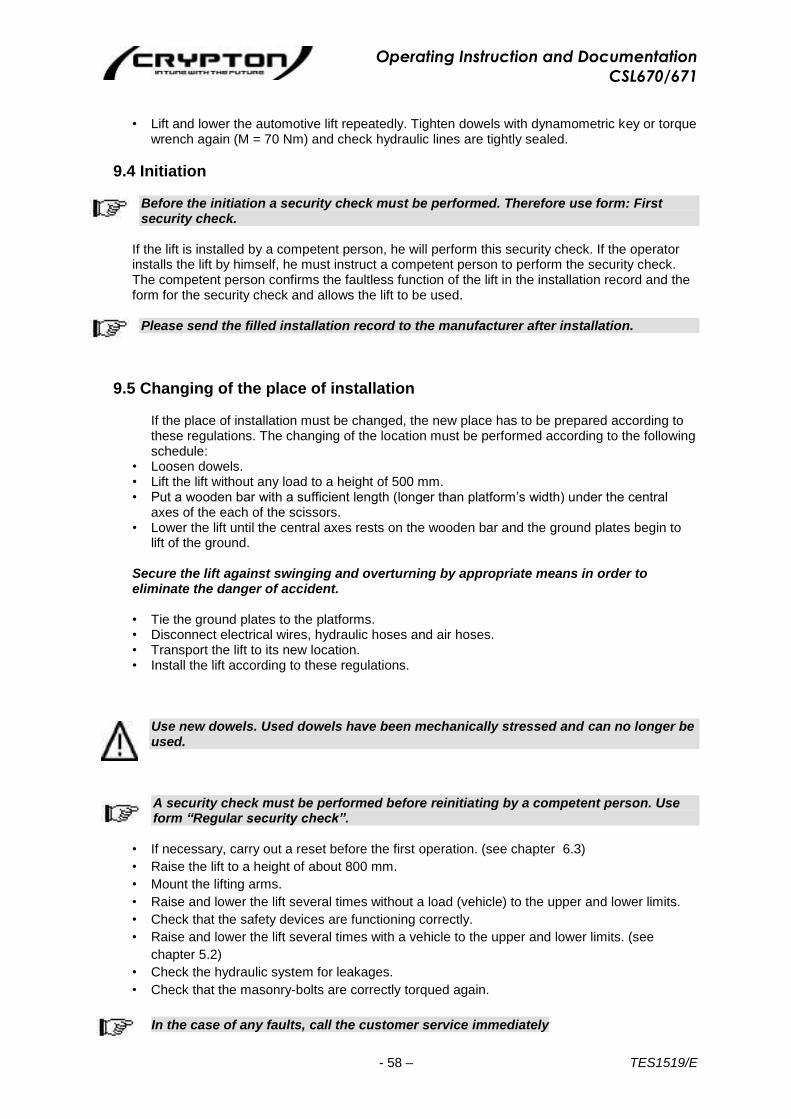
• Lift and lower the automotive lift repeatedly. Tighten dowels with dynamometric key or torque
wrench again (M = 70 Nm) and check hydraulic lines are tightly sealed.
9.4 Initiation
Before the initiation a security check must be performed. Therefore use form: First security check.
If the lift is installed by a competent person, he will perform this security check. If the operator installs the lift by himself, he must instruct a competent person to perform the security check. The competent person confirms the faultless function of the lift in the installation record and the form for the security check and allows the lift to be used.
Please send the filled installation record to the manufacturer after installation.
9.5 Changing of the place of installation If the place of installation must be changed, the new place has to be prepared according to these regulations. The changing of the location must be performed according to the following schedule:
• Loosen dowels. • Lift the lift without any load to a height of 500 mm. • Put a wooden bar with a sufficient length (longer than platform’s width) under the central
axes of the each of the scissors. • Lower the lift until the central axes rests on the wooden bar and the ground plates begin to
lift of the ground. Secure the lift against swinging and overturning by appropriate means in order to eliminate the danger of accident. • Tie the ground plates to the platforms. • Disconnect electrical wires, hydraulic hoses and air hoses. • Transport the lift to its new location. • Install the lift according to these regulations.
Use new dowels. Used dowels have been mechanically stressed and can no longer be used.
A security check must be performed before reinitiating by a competent person. Use form “Regular security check”.
• If necessary, carry out a reset before the first operation. (see chapter 6.3)
• Raise the lift to a height of about 800 mm.
• Mount the lifting arms.
• Raise and lower the lift several times without a load (vehicle) to the upper and lower limits.
• Check that the safety devices are functioning correctly.
• Raise and lower the lift several times with a vehicle to the upper and lower limits. (see
chapter 5.2)
• Check the hydraulic system for leakages.
• Check that the masonry-bolts are correctly torqued again.
In the case of any faults, call the customer service immediately

Operating Instruction and Documentation
CSL670/671
- 59 – TES1519/E
Pic 13: Connection of hydraulic hoses in command unit
Pic 14: Hydraulic hoses paths from command unit to the lift
Pic.15 Electrical parts in command unit
Operating Instruction and Documentation
CSL670/671
- 60 – TES1519/E
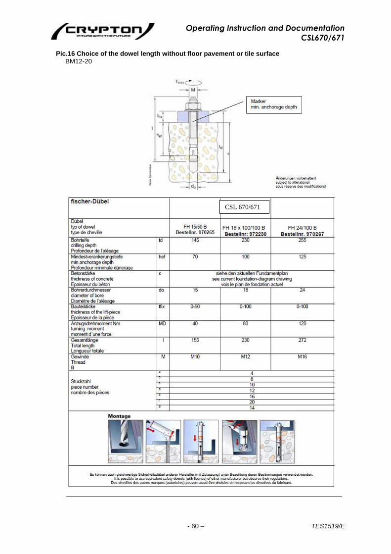
Pic.16 Choice of the dowel length without floor pavement or tile surface
BM12-20
CSL 670/671
Operating Instruction and Documentation
CSL670/671
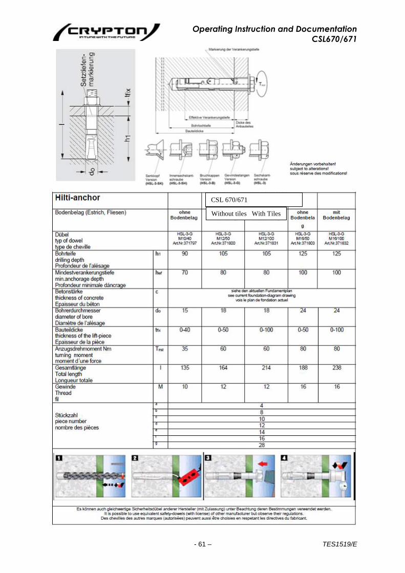
- 61 – TES1519/E
CSL 670/671
Without tiles With Tiles
Operating Instruction and Documentation
CSL670/671
- 62 – TES1519/E
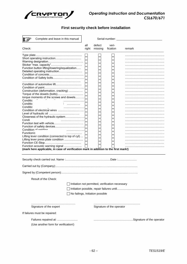
First security check before installation
Complete and leave in this manual Serial-number: _____________________________
all defect veri- Check: right missing fication remark ------------------------------------------------------------------------------------------------------------------------------------------------------ Type plate........................................................... .................................................. Short operating instruction................................. .................................................. Warning designation.......................................….. .................................................. Sticker “max. capacity”...................................…. .................................................. Function button lifting/lowering/equalization….. .................................................. Detailed operating instruction.........................…. .................................................. Condition of concrete............................................ .................................................. Condition of Safety bolts............….....……….…… .................................................. .......................................................................... .................................................. Condition of automotive lift................................. .................................................. Condition of paint............................................…... .................................................. Construction (deformation, cracking) .............…. .................................................. Torque of the dowels (bolts)................................. .................................................. torque moments of the screws and dowels.....…... .................................................. Condition of operating unit.............................….... .................................................. Condition of surface of piston rod ...........….. .................................................. Condition of coverings.......................................…. .................................................. Condition of electrical wires ..........................…... .................................................. Level of hydraulic oil ................................…... .................................................. Closeness of the hydraulic system...................….. .................................................. Condition of hydraulic hoses............................….. .................................................. Function test with vehicle................................….. .................................................. Function of safety devices...............................…... .................................................. Condition of welding........................................…... .................................................. Function/condition of ratchet.......………............. .................................................. Lifting lever condition (connected to top of cyl) … .................................................. Lifting lever press plate condition ........................ .................................................. Function CE-Stop…………................................ ..…............................................ Function acoustic warning signal …………........ .................................................. (mark here applicable, in case of verification mark in addition to the first mark!)
Security check carried out. Name :.........................................................Date :........................ Carried out by (Company):...........................................................……...................................... Signed by (Competent person):....................................................................................………..
Result of the Check:
Initiation not permitted, verification necessary
Initiation possible, repair failures until.........................................................
No failings, Initiation possible
........................................................ ........................................................... Signature of the expert Signature of the operator
If failures must be repaired:
Failures repaired at: .......................... ..................................................Signature of the operator
(Use another form for verification!)

Operating Instruction and Documentation
CSL670/671
- 63 – TES1519/E
Regular security check and Maintenance
Complete and leave in this manual Serial-number:_____________________________
all defect veri- Check: right missing fication remark ------------------------------------------------------------------------------------------------------------------------------------------------------ Type plate........................................................... .................................................. Short operating instruction................................. .................................................. Warning designation.......................................….. .................................................. Sticker “max. capacity”...................................…. .................................................. Function button lifting/lowering/equalization….. .................................................. Detailed operating instruction.........................…. .................................................. Condition of concrete............................................ .................................................. Condition of Safety bolts..................……….…… .................................................. .......................................................................... .................................................. Function play detector / lamp / press button.….. .................................................. Condition of automotive lift................................. .................................................. Condition of paint............................................…... .................................................. Construction (deformation, cracking) .............…. .................................................. Torque of the dowels (bolts)................................. .................................................. torque moments of the screws and dowels.....…... .................................................. Condition of operating unit.............................….... .................................................. Condition of surface of piston rod ...........….. .................................................. Condition of coverings.......................................…. .................................................. Condition of electrical wires ..........................…... .................................................. Level of hydraulic oil ................................…... .................................................. Closeness of the hydraulic system...................….. .................................................. Condition of hydraulic hoses............................….. .................................................. Function test with vehicle................................….. .................................................. Function safety devices..................................…... .................................................. Condition of welding........................................…... .................................................. Function/condition of ratchet.......………............. .................................................. Lifting lever condition (connected to top of cyl) … .................................................. Lifting lever press plate condition ........................ .................................................. Function CE-Stop …………............................... ..…............................................ Function acoustic warning signal …………........ .................................................. (mark here applicable, in case of verification mark in addition to the first mark!)
Security check carried out. Name :.........................................................Date :........................ Carried out by (Company):...........................................................……...................................... Signed by (Competent person):....................................................................................………..
Result of the Check:
Initiation not permitted, verification necessary
Initiation possible, repair failures until.........................................................
No failings, Initiation possible
........................................................ ........................................................... Signature of the expert Signature of the operator
If failures must be repaired:
Failures repaired at: .......................... ...................................................signature of the operator
(Use another form for verification!)

Operating Instruction and Documentation
CSL670/671
- 64 – TES1519/E
Regular security check and Maintenance
Complete and leave in this manual Serial-number:_____________________________
all defect veri- Check: right missing fication remark ------------------------------------------------------------------------------------------------------------------------------------------------------ Type plate........................................................... .................................................. Short operating instruction................................. .................................................. Warning designation.......................................….. .................................................. Sticker “max. capacity”...................................…. .................................................. Function button lifting/lowering/equalization….. .................................................. Detailed operating instruction.........................…. .................................................. Condition of concrete............................................ .................................................. Condition of Safety bolts............….....……….…… .................................................. .......................................................................... .................................................. Function play detector / lamp / press button.….. .................................................. Condition of automotive lift................................. .................................................. Condition of paint............................................…... .................................................. Construction (deformation, cracking) .............…. .................................................. Torque of the dowels (bolts)................................. .................................................. torque moments of the screws and dowels.....…... .................................................. Condition of operating unit.............................….... .................................................. Condition of surface of piston rod ...........….. .................................................. Condition of coverings.......................................…. .................................................. Condition of electrical wires ..........................…... .................................................. Level of hydraulic oil ................................…... .................................................. Closeness of the hydraulic system...................….. .................................................. Condition of hydraulic hoses............................….. .................................................. Function test with vehicle................................….. .................................................. Function safety devices..................................…... .................................................. Condition of welding........................................…... .................................................. Function/condition of ratchet.......………............. .................................................. Lifting lever condition (connected to top of cyl) … .................................................. Lifting lever press plate condition ........................ .................................................. Function CE-Stop …………................................ ..…............................................ Function acoustic warning signal …………........ .................................................. (mark here applicable, in case of verification mark in addition to the first mark!)
Security check carried out. Name :.........................................................Date :........................ Carried out by (Company):...........................................................……...................................... Signed by (Competent person):....................................................................................………..
Result of the Check:
Initiation not permitted, verification necessary
Initiation possible, repair failures until.........................................................
No failings, Initiation possible
........................................................ ........................................................... Signature of the expert Signature of the operator
If failures must be repaired:
Failures repaired at: .......................... ..................................................Signature of the operator
(Use another form for verification!)

Operating Instruction and Documentation
CSL670/671
- 65 – TES1519/E
Regular security check and Maintenance
Complete and leave in this manual Serial-number:_____________________________
all defect veri- Check: right missing fication remark ------------------------------------------------------------------------------------------------------------------------------------------------------ Type plate........................................................... .................................................. Short operating instruction................................. .................................................. Warning designation.......................................….. .................................................. Sticker “max. capacity”...................................…. .................................................. Function button lifting/lowering/equalization….. .................................................. Detailed operating instruction.........................…. .................................................. Condition of concrete............................................ .................................................. Condition of Safety bolts............….....……….…… .................................................. .......................................................................... .................................................. Function play detector / lamp / press button.….. .................................................. Condition of automotive lift................................. .................................................. Condition paint.............................................…... .................................................. Construction (deformation, cracking) .............…. .................................................. Torque of the dowels (bolts)................................. .................................................. torque moments of the screws and dowels.....…... .................................................. Condition of operating unit.............................….... .................................................. Condition of surface of piston rod ...........….. .................................................. Condition of coverings.......................................…. .................................................. Condition of electrical wires ..........................…... .................................................. Level of hydraulic oil ................................…... .................................................. Closeness of the hydraulic system...................….. .................................................. Condition hydraulic hoses...............................….. .................................................. Function test with vehicle................................….. .................................................. Function safety devices..................................…... .................................................. Condition of welding........................................…... .................................................. Function/condition of ratchet.......………............. .................................................. Lifting lever condition (connected to top of cyl) … .................................................. Lifting lever press plate condition ........................ .................................................. Function CE-Stop …………............................... ..…............................................ Function acoustic warning signal …………......... .................................................. (mark here applicable, in case of verification mark in addition to the first mark!)
Security check carried out. Name :.........................................................Date :........................ Carried out by (Company):...........................................................……...................................... Signed by (Competent person):....................................................................................………..
Result of the Check:
Initiation not permitted, verification necessary
Initiation possible, repair failures until.........................................................
No failings, Initiation possible
........................................................ ........................................................... Signature of the expert Signature of the operator
If failures must be repaired:
Failures repaired at: .......................... ..................................................Signature of the operator
(Use another form for verification!)

Operating Instruction and Documentation
CSL670/671
- 66 – TES1519/E
Regular security check and Maintenance
Complete and leave in this manual Serial-number:_____________________________
all defect veri- Check: right missing fication remark ------------------------------------------------------------------------------------------------------------------------------------------------------ Type plate........................................................... .................................................. Short operating instruction................................. .................................................. Warning designation.......................................….. .................................................. Sticker “max. capacity”...................................…. .................................................. Function button lifting/lowering/equalization….. .................................................. Detailed operating instruction.........................…. .................................................. Condition of concrete............................................ .................................................. Condition of Safety bolts............….....……….…… .................................................. .......................................................................... .................................................. Function play detector / lamp / press button.….. .................................................. Condition of automotive lift................................. .................................................. Condition of paint............................................…... .................................................. Construction (deformation, cracking) .............…. .................................................. Torque of the dowels (bolts)................................. .................................................. torque moments of the screws and dowels.....…... .................................................. Condition of operating unit.............................….... .................................................. Condition of surface of piston rod ...........….. .................................................. Condition of coverings.......................................…. .................................................. Condition of electrical wires ..........................…... .................................................. Level of hydraulic oil ................................…... .................................................. Closeness of the hydraulic system...................….. .................................................. Condition of hydraulic hoses............................….. .................................................. Function test with vehicle................................….. .................................................. Function safety devices..................................…... .................................................. Condition of welding........................................…... .................................................. Function/condition of ratchet.......………............. .................................................. Lifting lever condition (connected to top of cyl) … .................................................. Lifting lever press plate condition ........................ .................................................. Function CE-Stop …………................................ ..…............................................ Function acoustic warning signal …………........ .................................................. (mark here applicable, in case of verification mark in addition to the first mark!)
Security check carried out. Name :.........................................................Date :........................ Carried out by (Company):...........................................................……...................................... Signed by (Competent person):....................................................................................………..
Result of the Check:
Initiation not permitted, verification necessary
Initiation possible, repair failures until.........................................................
No failings, Initiation possible
........................................................ ........................................................... Signature of the expert Signature of the operator
If failures must be repaired:
Failures repaired at: .......................... .................................................Signature of the operator
(Use another form for verification!)
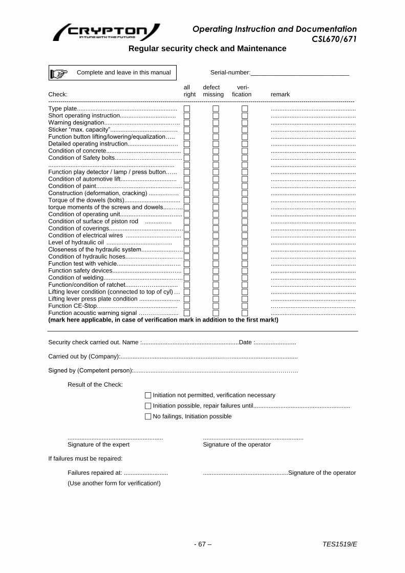
Operating Instruction and Documentation
CSL670/671
- 67 – TES1519/E
Regular security check and Maintenance
Complete and leave in this manual Serial-number:_____________________________
all defect veri- Check: right missing fication remark ------------------------------------------------------------------------------------------------------------------------------------------------------ Type plate........................................................... .................................................. Short operating instruction................................. .................................................. Warning designation.......................................….. .................................................. Sticker “max. capacity”...................................…. .................................................. Function button lifting/lowering/equalization….. .................................................. Detailed operating instruction.........................…. .................................................. Condition of concrete............................................ .................................................. Condition of Safety bolts............….....……….…… .................................................. .......................................................................... .................................................. Function play detector / lamp / press button.….. .................................................. Condition of automotive lift................................. .................................................. Condition of paint............................................…... .................................................. Construction (deformation, cracking) .............…. .................................................. Torque of the dowels (bolts)................................. .................................................. torque moments of the screws and dowels.....…... .................................................. Condition of operating unit.............................….... .................................................. Condition of surface of piston rod ..........….. .................................................. Condition of coverings.......................................…. .................................................. Condition of electrical wires ..........................…... .................................................. Level of hydraulic oil ................................…... .................................................. Closeness of the hydraulic system...................….. .................................................. Condition of hydraulic hoses............................….. .................................................. Function test with vehicle................................….. .................................................. Function safety devices..................................…... .................................................. Condition of welding........................................…... .................................................. Function/condition of ratchet.......………............. .................................................. Lifting lever condition (connected to top of cyl) … .................................................. Lifting lever press plate condition ........................ .................................................. Function CE-Stop…………................................. ..…............................................ Function acoustic warning signal …………......... .................................................. (mark here applicable, in case of verification mark in addition to the first mark!)
Security check carried out. Name :.........................................................Date :........................ Carried out by (Company):...........................................................……...................................... Signed by (Competent person):....................................................................................………..
Result of the Check:
Initiation not permitted, verification necessary
Initiation possible, repair failures until.........................................................
No failings, Initiation possible
........................................................ ........................................................... Signature of the expert Signature of the operator
If failures must be repaired:
Failures repaired at: .......................... ..................................................Signature of the operator
(Use another form for verification!)

Operating Instruction and Documentation
CSL670/671
- 68 – TES1519/E
Regular security check and Maintenance
Complete and leave in this manual Serial-number:_____________________________
all defect veri- Check: right missing fication remark ------------------------------------------------------------------------------------------------------------------------------------------------------ Type plate........................................................... .................................................. Short operating instruction................................. .................................................. Warning designation.......................................….. .................................................. Sticker “max. capacity”...................................…. .................................................. Function button lifting/lowering/equalization….. .................................................. Detailed operating instruction.........................…. .................................................. Condition of concrete............................................ .................................................. Condition of Safety bolts...........….....……….…… .................................................. .......................................................................... .................................................. Function play detector / lamp / press button.….. .................................................. Condition of automotive lift................................. .................................................. Condition of paint............................................…... .................................................. Construction (deformation, cracking) .............…. .................................................. Torque of the dowels (bolts)................................. .................................................. torque moments of the screws and dowels.....…... .................................................. Condition of operating unit.............................….... .................................................. Condition of surface of piston rod ...........….. .................................................. Condition of coverings.......................................…. .................................................. Condition of electrical wires ..........................…... .................................................. Level of hydraulic oil ................................…... .................................................. Closeness of the hydraulic system...................….. .................................................. Condition of hydraulic hoses............................….. .................................................. Function test with vehicle................................….. .................................................. Function of safety devices...............................…... .................................................. Condition of welding........................................…... .................................................. Function/condition of ratchet.......………............. .................................................. Lifting lever condition (connected to top of cyl) … .................................................. Lifting lever press plate condition ........................ .................................................. Function CE-Stop …………................................ ..…............................................ Function acoustic warning signal …………........ .................................................. (mark here applicable, in case of verification mark in addition to the first mark!)
Security check carried out. Name :.........................................................Date :........................ Carried out by (Company):...........................................................……...................................... Signed by (Competent person):....................................................................................………..
Result of the Check:
Initiation not permitted, verification necessary
Initiation possible, repair failures until.........................................................
No failings, Initiation possible
........................................................ ........................................................... Signature of the expert Signature of the operator
If failures must be repaired:
Failures repaired at: .......................... .................................................Signature of the operator
(Use another form for verification!)
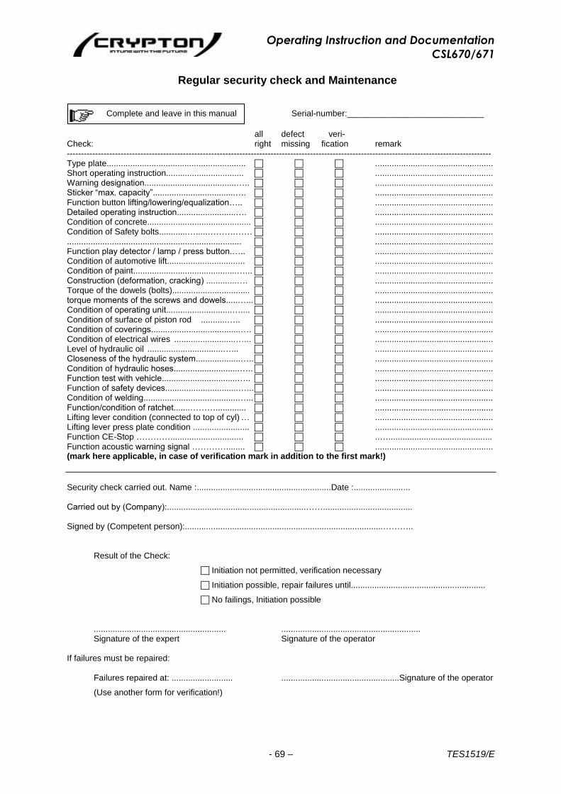
Operating Instruction and Documentation
CSL670/671
- 69 – TES1519/E
Regular security check and Maintenance
Complete and leave in this manual Serial-number:_____________________________
all defect veri- Check: right missing fication remark ------------------------------------------------------------------------------------------------------------------------------------------------------ Type plate........................................................... .................................................. Short operating instruction................................. .................................................. Warning designation.......................................….. .................................................. Sticker “max. capacity”...................................…. .................................................. Function button lifting/lowering/equalization….. .................................................. Detailed operating instruction.........................…. .................................................. Condition of concrete............................................ .................................................. Condition of Safety bolts............….....……….…… .................................................. .......................................................................... .................................................. Function play detector / lamp / press button.….. .................................................. Condition of automotive lift................................. .................................................. Condition of paint............................................…... .................................................. Construction (deformation, cracking) .............…. .................................................. Torque of the dowels (bolts)................................. .................................................. torque moments of the screws and dowels.....…... .................................................. Condition of operating unit............................….... .................................................. Condition of surface of piston rod ...........….. .................................................. Condition of coverings......................................…. .................................................. Condition of electrical wires ..........................…... .................................................. Level of hydraulic oil ................................…... .................................................. Closeness of the hydraulic system...................….. .................................................. Condition of hydraulic hoses............................….. .................................................. Function test with vehicle................................….. .................................................. Function of safety devices...............................…... .................................................. Condition of welding........................................…... .................................................. Function/condition of ratchet.......………............. .................................................. Lifting lever condition (connected to top of cyl) … .................................................. Lifting lever press plate condition ........................ .................................................. Function CE-Stop …………............................... ..…............................................ Function acoustic warning signal …………........ .................................................. (mark here applicable, in case of verification mark in addition to the first mark!)
Security check carried out. Name :.........................................................Date :........................ Carried out by (Company):...........................................................……...................................... Signed by (Competent person):....................................................................................………..
Result of the Check:
Initiation not permitted, verification necessary
Initiation possible, repair failures until.........................................................
No failings, Initiation possible
........................................................ ........................................................... Signature of the expert Signature of the operator
If failures must be repaired:
Failures repaired at: .......................... ..................................................Signature of the operator
(Use another form for verification!)
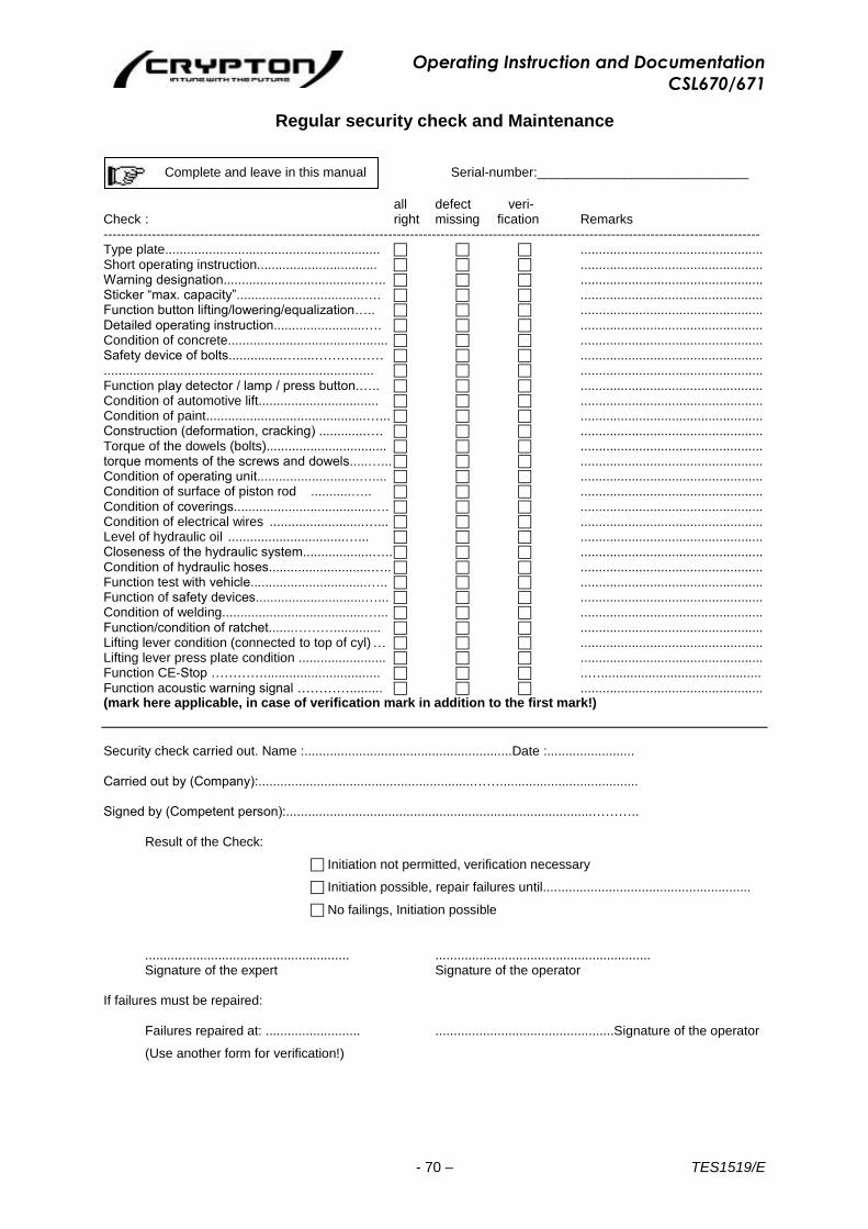
Operating Instruction and Documentation
CSL670/671
- 70 – TES1519/E
Regular security check and Maintenance
Complete and leave in this manual Serial-number:_____________________________
all defect veri- Check : right missing fication Remarks ------------------------------------------------------------------------------------------------------------------------------------------------------ Type plate........................................................... .................................................. Short operating instruction................................. .................................................. Warning designation.......................................….. .................................................. Sticker “max. capacity”...................................…. .................................................. Function button lifting/lowering/equalization….. .................................................. Detailed operating instruction.........................…. .................................................. Condition of concrete............................................ .................................................. Safety device of bolts...............….....……….…… .................................................. .......................................................................... .................................................. Function play detector / lamp / press button.….. .................................................. Condition of automotive lift................................. .................................................. Condition of paint............................................…... .................................................. Construction (deformation, cracking) .............…. .................................................. Torque of the dowels (bolts)................................. .................................................. torque moments of the screws and dowels.....…... .................................................. Condition of operating unit............................….... .................................................. Condition of surface of piston rod ...........….. .................................................. Condition of coverings......................................…. .................................................. Condition of electrical wires ..........................…... .................................................. Level of hydraulic oil ................................…... .................................................. Closeness of the hydraulic system...................….. .................................................. Condition of hydraulic hoses............................….. .................................................. Function test with vehicle................................….. .................................................. Function of safety devices..............................…... .................................................. Condition of welding.......................................…... .................................................. Function/condition of ratchet.......………............. .................................................. Lifting lever condition (connected to top of cyl) … .................................................. Lifting lever press plate condition ........................ .................................................. Function CE-Stop …………................................ ..…............................................ Function acoustic warning signal …………......... .................................................. (mark here applicable, in case of verification mark in addition to the first mark!)
Security check carried out. Name :.........................................................Date :........................ Carried out by (Company):...........................................................……...................................... Signed by (Competent person):....................................................................................………..
Result of the Check:
Initiation not permitted, verification necessary
Initiation possible, repair failures until.........................................................
No failings, Initiation possible
........................................................ ........................................................... Signature of the expert Signature of the operator
If failures must be repaired:
Failures repaired at: .......................... .................................................Signature of the operator
(Use another form for verification!)
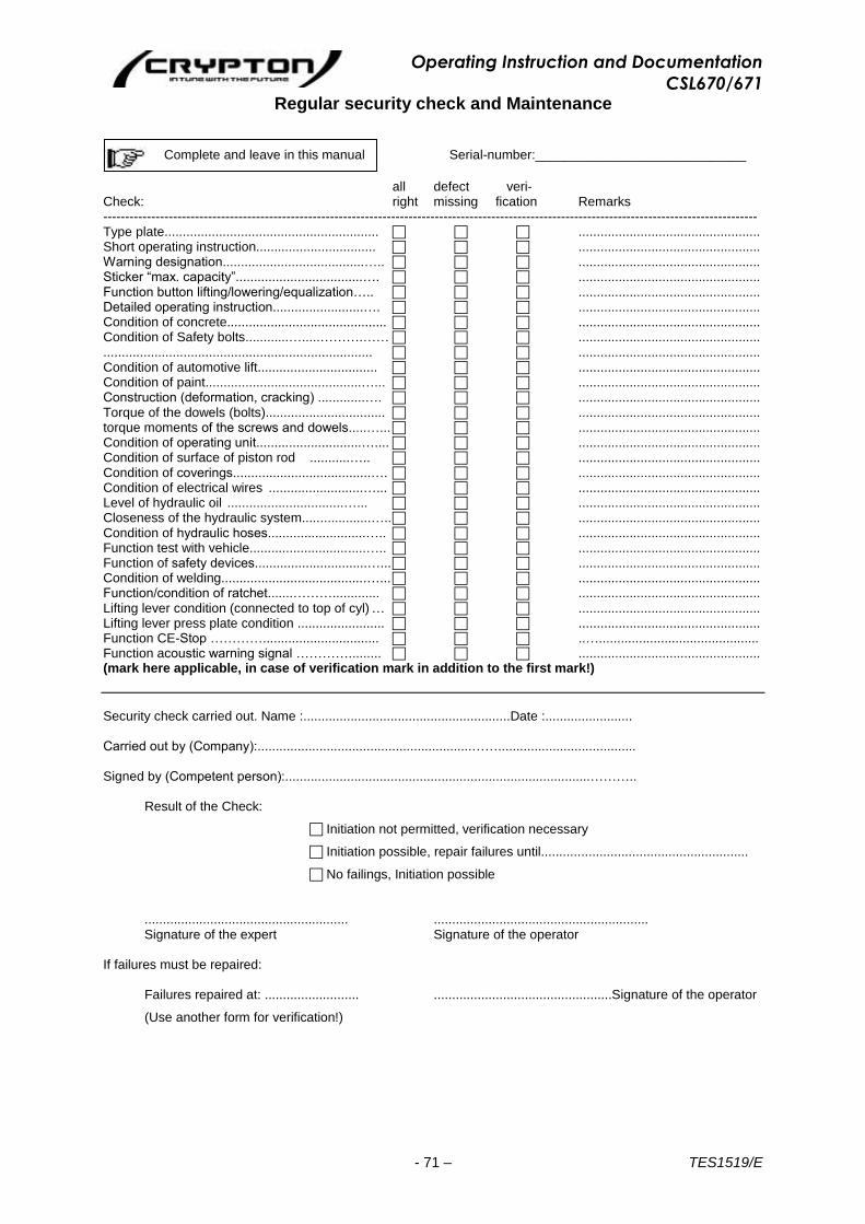
Operating Instruction and Documentation
CSL670/671
- 71 – TES1519/E
Regular security check and Maintenance
Complete and leave in this manual Serial-number:_____________________________
all defect veri- Check: right missing fication Remarks ------------------------------------------------------------------------------------------------------------------------------------------------------ Type plate........................................................... .................................................. Short operating instruction................................. .................................................. Warning designation.......................................….. .................................................. Sticker “max. capacity”...................................…. .................................................. Function button lifting/lowering/equalization….. .................................................. Detailed operating instruction.........................…. .................................................. Condition of concrete............................................ .................................................. Condition of Safety bolts............….....……….…… .................................................. .......................................................................... .................................................. Condition of automotive lift................................. .................................................. Condition of paint...........................................…... .................................................. Construction (deformation, cracking) .............…. .................................................. Torque of the dowels (bolts)................................. .................................................. torque moments of the screws and dowels.....…... .................................................. Condition of operating unit.............................….... .................................................. Condition of surface of piston rod ...........….. .................................................. Condition of coverings......................................…. .................................................. Condition of electrical wires ..........................…... .................................................. Level of hydraulic oil ................................…... .................................................. Closeness of the hydraulic system...................….. .................................................. Condition of hydraulic hoses...........................….. .................................................. Function test with vehicle................................….. .................................................. Function of safety devices...............................…... .................................................. Condition of welding........................................…... .................................................. Function/condition of ratchet.......………............. .................................................. Lifting lever condition (connected to top of cyl) … .................................................. Lifting lever press plate condition ........................ .................................................. Function CE-Stop …………................................ ..…............................................ Function acoustic warning signal …………......... .................................................. (mark here applicable, in case of verification mark in addition to the first mark!)
Security check carried out. Name :.........................................................Date :........................ Carried out by (Company):...........................................................……...................................... Signed by (Competent person):....................................................................................………..
Result of the Check:
Initiation not permitted, verification necessary
Initiation possible, repair failures until.........................................................
No failings, Initiation possible
........................................................ ........................................................... Signature of the expert Signature of the operator
If failures must be repaired:
Failures repaired at: .......................... .................................................Signature of the operator
(Use another form for verification!)

Operating Instruction and Documentation
CSL670/671
- 72 – TES1519/E
Extraordinary security check
Complete and leave in this manual Serial-number:_____________________________
all defect veri- Check: right missing fication Remarks ------------------------------------------------------------------------------------------------------------------------------------------------------ Type plate........................................................... .................................................. Short operating instruction................................. .................................................. Warning designation.......................................….. .................................................. Sticker “max. capacity”...................................…. .................................................. Function button lifting/lowering/equalization….. .................................................. Detailed operating instruction.........................…. .................................................. Condition of concrete............................................ .................................................. Condition of Safety bolts............….....……….…… .................................................. .......................................................................... .................................................. Function play detector / lamp / press button.….. .................................................. Condition of automotive lift................................. .................................................. Condition of paint............................................…... .................................................. Construction (deformation, cracking) .............…. .................................................. Torque of the dowels (bolts)................................. .................................................. torque moments of the screws and dowels.....…... .................................................. Condition of operating unit.............................….... .................................................. Condition of surface of piston rod ...........….. .................................................. Condition of coverings.......................................…. .................................................. Condition of electrical wires ..........................…... .................................................. Level of hydraulic oil ................................…... .................................................. Closeness of the hydraulic system...................….. .................................................. Condition hydraulic hoses...............................….. .................................................. Function test with vehicle................................….. .................................................. Function of safety devices..............................…... .................................................. Condition of welding........................................…... .................................................. Function/condition of ratchet.......………............. .................................................. Lifting lever condition (connected to top of cyl) … .................................................. Lifting lever press plate condition ........................ .................................................. Function CE-Stop…………................................. ..…............................................ Function acoustic warning signal …………........ .................................................. (mark here applicable, in case of verification mark in addition to the first mark!)
Security check carried out. Name :.........................................................Date :........................ Carried out by (Company):...........................................................……...................................... Signed by (Competent person):....................................................................................………..
Result of the Check:
Initiation not permitted, verification necessary
Initiation possible, repair failures until.........................................................
No failings, Initiation possible
........................................................ ........................................................... Signature of the expert Signature of the operator
If failures must be repaired:
Failures repaired at: .......................... ................................................Signature of the operator
(Use another form for verification!)
CPD600 Assembly Details
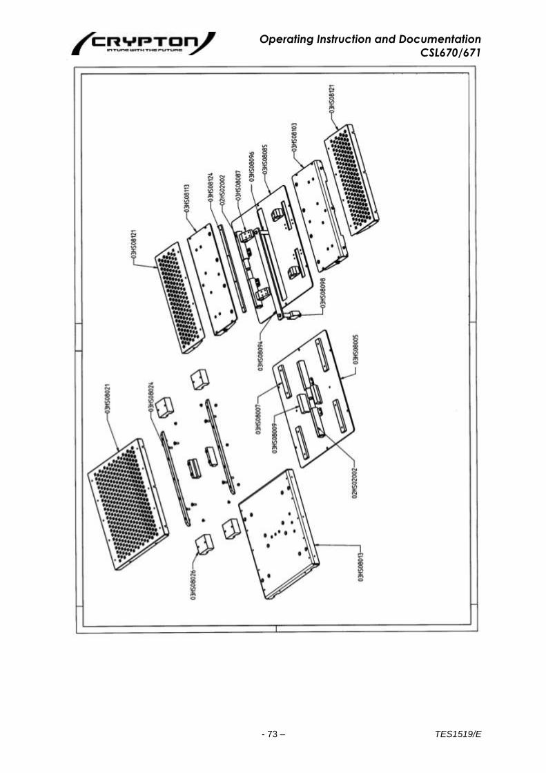
Operating Instruction and Documentation
CSL670/671
- 73 – TES1519/E

Operating Instruction and Documentation
CSL670/671
- 74 – TES1519/E
Spare part list
Pages: 74 to 96

Operating Instruction and Documentation
CSL670/671
- 75 – TES1519/E
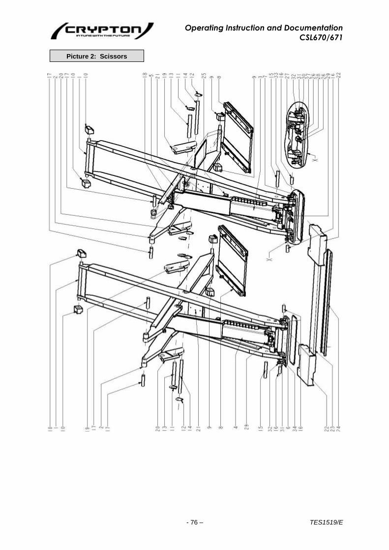
Operating Instruction and Documentation
CSL670/671
- 76 – TES1519/E
Picture 2: Scissors
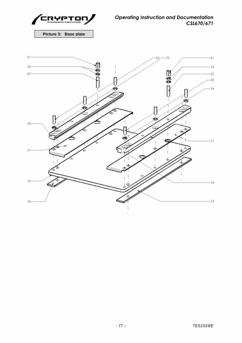
Operating Instruction and Documentation
CSL670/671
- 77 – TES1519/E
Picture 3: Base plate
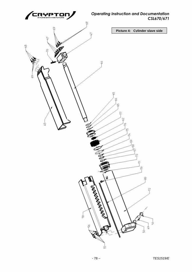
Operating Instruction and Documentation
CSL670/671
- 78 – TES1519/E
Picture 4: Cylinder slave side

Operating Instruction and Documentation
CSL670/671
- 79 – TES1519/E
Picture 5: Cylinder master side
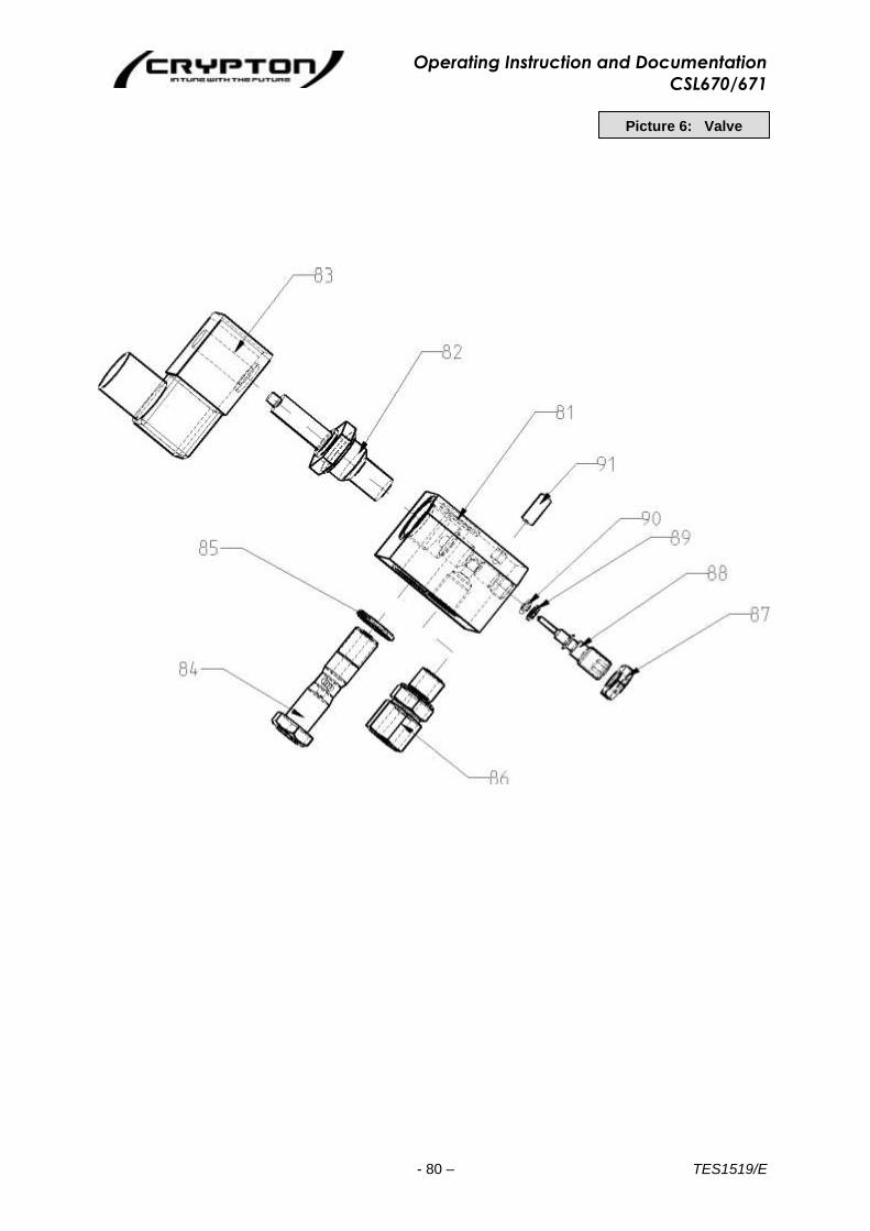
Operating Instruction and Documentation
CSL670/671
- 80 – TES1519/E
Picture 6: Valve
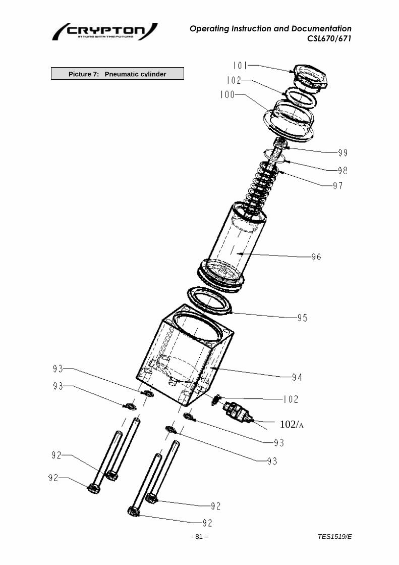
Operating Instruction and Documentation
CSL670/671
- 81 – TES1519/E
Picture 7: Pneumatic cylinder
102/A
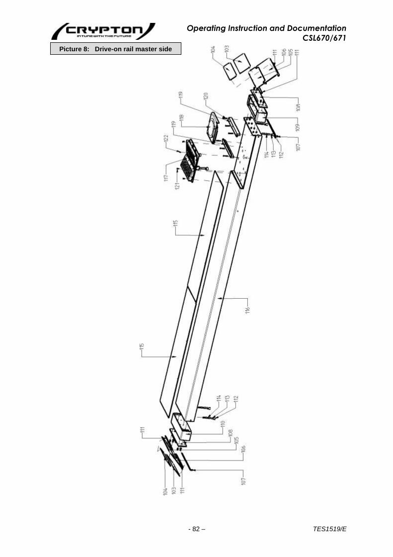
Operating Instruction and Documentation
CSL670/671
- 82 – TES1519/E
Picture 8: Drive-on rail master side

Operating Instruction and Documentation
CSL670/671
- 83 – TES1519/E
Picture 9: Drive-on rail slave side

Operating Instruction and Documentation
CSL670/671
- 84 – TES1519/E
Picture 10: Traverse

Operating Instruction and Documentation
CSL670/671
- 85 – TES1519/E
Picture 11: Hydraulic Unit front

Operating Instruction and Documentation
CSL670/671
- 86 – TES1519/E
Picture 11a: Hydraulic unit rear
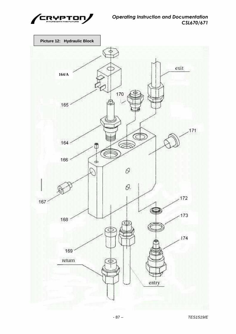
Operating Instruction and Documentation
CSL670/671
- 87 – TES1519/E
Picture 12: Hydraulic Block
164/A

Operating Instruction and Documentation
CSL670/671
- 88 – TES1519/E
Picture 13: Bypass valve

Operating Instruction and Documentation
CSL670/671
- 89 – TES1519/E
Picture 14: lamp
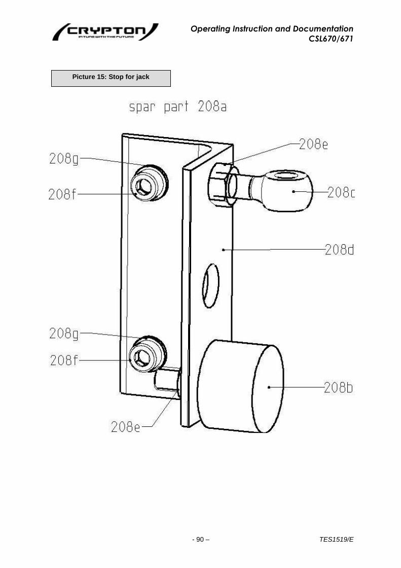
Operating Instruction and Documentation
CSL670/671
- 90 – TES1519/E
Picture 15: Stop for jack

Operating Instruction and Documentation
CSL670/671
- 91 – TES1519/E
No.
Part No.
Description
01 Lift order No. Lift complete
02 See picture 8 Drive-on rail master side
03 See picture 9 Drive-on rail slave side
04 See picture 10 Traverse
05 See picture 11-11a Hydraulic unit
1 050ULN06003 Scissors outside
2 050ULN06073 Scissors inside
3 040ULN22037 Cylinder slave side
4 040ULN22001 Cylinder master side
5 050ULN26020 Cable channel
6 050ULN05025 Plate, bottom master side
7 050ULN05035 Plate, bottom slave side
8 050ULN05010 Plate, bottom
9 050ULN06021 Sliding block bottom
10 050ULN06030 Sliding block above
11 040ULN06049 Locking plate
12 040ULN06046 Locking plate
13 032ULN06048 Axle cylinder
14 040ULN06045 Bolt center
15 030ULN06070 Bolt cylinder
16 040ULN06110 Bolt lower
17 040ULN06115 Bolt upper
18 029UL3001 Metal sheet
19 040ULN06033 Suspension cylinder
20 040ULN06030 Suspension cylinder
21 032ULN06027 Forcing plate
22 050ULN09003 Covering
23 050ULN29017 Covering hoses
24 050ULN29016 Tray hoses
25 030ULN10036 Pneumatic cylinder
26 029UL05006 Metal sheet for limit switch
27 990004 Limit switch
28 9914830 Limit switch
29 030ULN02061 Valve complete
30 9439M16ZN Nut M16 DIN439B
31 9913M16X050ZN Set screw M16x50
32 030ULN45011 Hexagon nut
33 032ULN05004 Adjusting metal sheet
34 9913M16X050ZN Set screw M16x50
35 032ULN05015 Metal sheet

Operating Instruction and Documentation
CSL670/671
- 92 – TES1519/E
No.
Part No.
Description
36 050ULN405017 Base plate
37 050ULN05022 Crosshead guide
38 050ULN05030 Wrap around
39 9439M16ZN Nut M16 DIN439B
40 9913M16X050ZN Set screw M16x50
41 030ULN45011 Hexagon nut
42 9913M16X070ZN Set screw M16x70
43 032ULN02003 Cylinder tube master side
44 032ULN30016 Ratchet (tube) master side
45 032ULN10001 Ratchet
46 040ULN02009 Piston rod
47 030ULN22010 Bolt
48 030ULN02014 Guide bush master side
49 030ULN02002S1 Spacer tube
50 970071 Slide bearing
51 032ULN02002S1 Hydraulic pipe
52 9M10L Sleeve nut
53 97603A06.5x9.5 Gasket
54 9912M06X008ZN Socket screw
55 9912M06X012ZN Socket screw
56 9125M06A Bolt washer
57 985097 Rotating band
58 985220 Seal piston rod
59 985100 Rotating band
60 9OR94.62X5.33 O-ring seal
61 985101 Bearing ring
62 985099 Stripper
63 985096 Seal master side
64 025AL42020 Piston master side
65 985102 Bearing ring
66 9OR45.69x2.62 O-ring seal
67 029UL30011 Metal sheet
68 9933M08X016ZN Screw
69 9125M08A Bolt washer
70 91481D08X060 Retaining bush

Operating Instruction and Documentation
CSL670/671
- 93 – TES1519/E
No.
Part No.
Description
71 9914M06X008ZN Thread plug
72 032ULN02039 Cylinder tube slave side
73 030ULN02050 Guide bush slave side
74 9OR85.09x5.33 O-ring seal
75 985104 Bearing ring
76 985086 Seal slave side
77 025AL42059 Piston slave side
78 032ULN10017 Ratched (tube) slave side
79 9M8L Sleeve nut
80 032ULN02037S1 Hydraulic pipe
81 030ULN02062 Hydraulic block
82 980478 Magnet valve
83 980630 Magnet
84 030ULN02066 Banjo bolt
85 985037 Seal ring
86 9GE10PLRED Screw
87 9439M10ZN Nut M10 DIN439B
88 030ULN02064 Emergency lowering
89 980604 Bearing ring
90 9OR4.47X1.78 O-ring seal
91 96325D06X016 Plain pin
92 9912M04X045ZN Socket screw
93 97980M04ZN Spring ring
94 030ULN10037 Cylinder case
95 960001 Seal
96 9030ULN10039 Piston
97 9DFD-187ZN Compression spring
98 99021M05ZN Bolt washer
99 9912M05X055ZN Socket screw
100 030ULN10038 Guide bush
101 030ULN10045 Cover
102 9OR15.54X2.62 O-ring seal
102/A 960003 Screw connection
103 035ULN08058 Alu plank
104 035ULN08056 Alu plank
105 035UL28055 Safety against to roll back

Operating Instruction and Documentation
CSL670/671
- 94 – TES1519/E
No.
Part No.
Description
106 035UL48065 Ramp
107 Not yet allocated Amended New style Pin
108 035UL28070 Adapter metal sheet
109 050ULN08223 Extension ahead
110 050ULN08213 Extension rear
111 435H08097 Polyamid support
112 035UNI08415 Buffer
113 9439M016ZN Nut M16 DIN439B
114 9913M16X0140ZN Set screw M16x140
115 050ULN08820 Alu plank
116 050ULN08203 Drive-on rail master side
117 03HS08281 Spid right
118 1987009A42A Rotary disc (Sandpaper surface)
118 1987009A89A Rotary disc (Metal surface)
119 035ULN083851 Wrap-around
120 9912M08X070ZN Socket screw
121 9912M08X025ZN Socket screw
122 97991M008X020ZN Counter sunk screw
123 03HS080 Spid left
124 050ULN08303 Drive-on rail slave side
125 032ULB03210 Mounting plate for lamp
126 035ULN08676 Hanging up left
127 91478M20ZN Screw shackle
128 035ULN08678 Hanging up right
129 9933M08X25ZN Screw
130 035ULN01215 Upper section
131 035ULN01203 Lower surface
132 032ULN01040 Front sheet metal
133 990303 Motor 3,3kW
134 970290 Clutch
135 030ULN01025 Covering motor
136 980098 Oil level gauge
137 030ULN21076 Hydraulic block
138 030ULN01038 Holder for the pump
139 980282 Pump 2,7ccm
140 9EW10PL Union piece hyd.
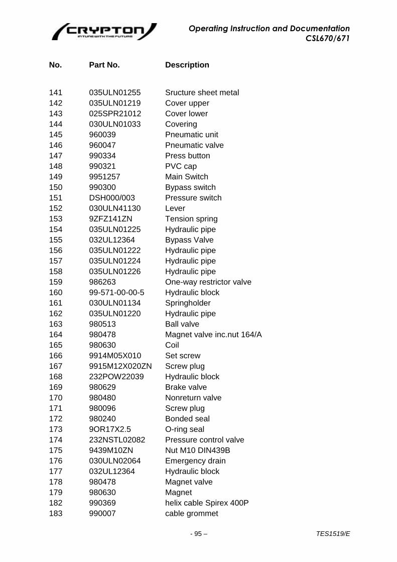
Operating Instruction and Documentation
CSL670/671
- 95 – TES1519/E
No.
Part No.
Description
141 035ULN01255 Sructure sheet metal
142 035ULN01219 Cover upper
143 025SPR21012 Cover lower
144 030ULN01033 Covering
145 960039 Pneumatic unit
146 960047 Pneumatic valve
147 990334 Press button
148 990321 PVC cap
149 9951257 Main Switch
150 990300 Bypass switch
151 DSH000/003 Pressure switch
152 030ULN41130 Lever
153 9ZFZ141ZN Tension spring
154 035ULN01225 Hydraulic pipe
155 032UL12364 Bypass Valve
156 035ULN01222 Hydraulic pipe
157 035ULN01224 Hydraulic pipe
158 035ULN01226 Hydraulic pipe
159 986263 One-way restrictor valve
160 99-571-00-00-5 Hydraulic block
161 030ULN01134 Springholder
162 035ULN01220 Hydraulic pipe
163 980513 Ball valve
164 980478 Magnet valve inc.nut 164/A
165 980630 Coil
166 9914M05X010 Set screw
167 9915M12X020ZN Screw plug
168 232POW22039 Hydraulic block
169 980629 Brake valve
170 980480 Nonreturn valve
171 980096 Screw plug
172 980240 Bonded seal
173 9OR17X2.5 O-ring seal
174 232NSTL02082 Pressure control valve
175 9439M10ZN Nut M10 DIN439B
176 030ULN02064 Emergency drain
177 032UL12364 Hydraulic block
178 980478 Magnet valve
179 980630 Magnet
182 990369 helix cable Spirex 400P
183 990007 cable grommet
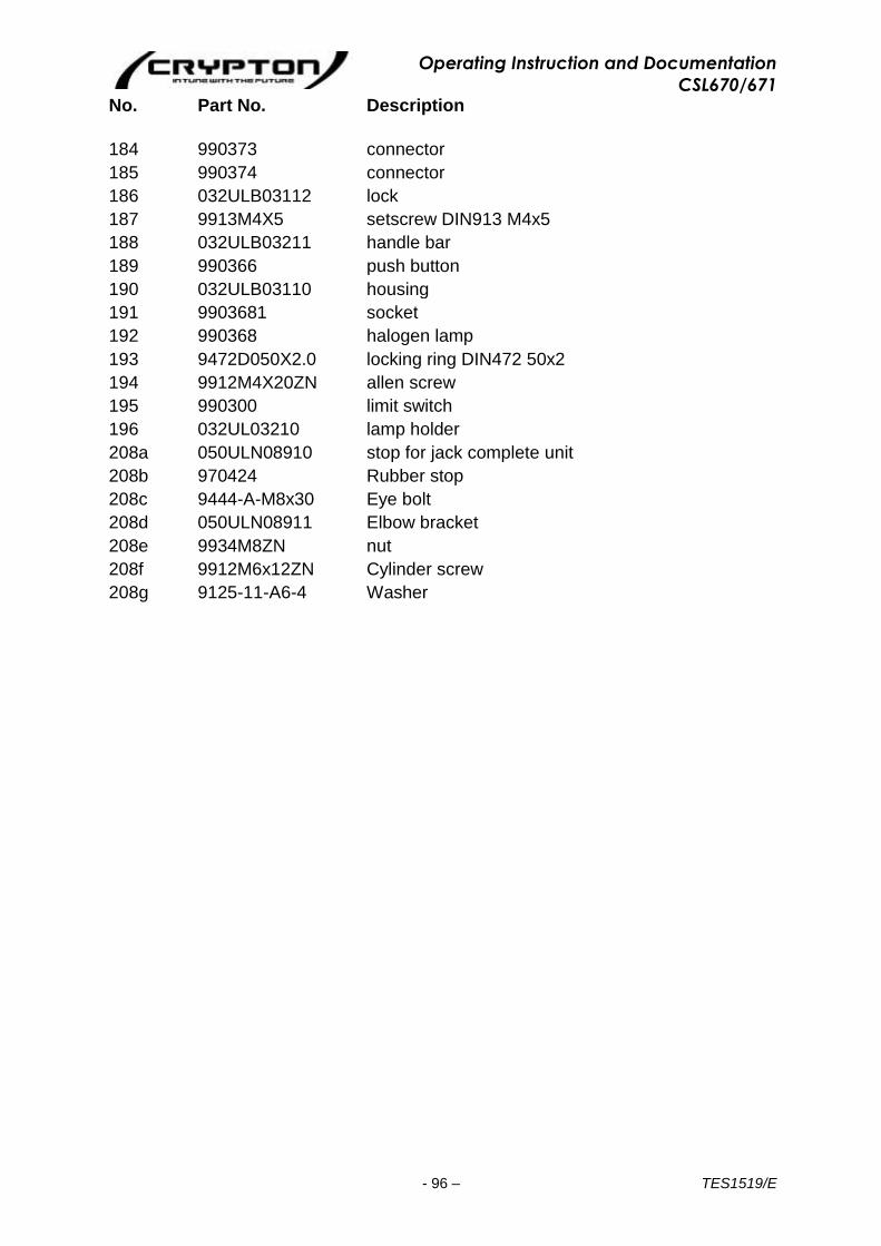
Operating Instruction and Documentation
CSL670/671
- 96 – TES1519/E
No.
Part No.
Description
184 990373 connector
185 990374 connector
186 032ULB03112 lock
187 9913M4X5 setscrew DIN913 M4x5
188 032ULB03211 handle bar
189 990366 push button
190 032ULB03110 housing
191 9903681 socket
192 990368 halogen lamp
193 9472D050X2.0 locking ring DIN472 50x2
194 9912M4X20ZN allen screw
195 990300 limit switch
196 032UL03210 lamp holder
208a 050ULN08910 stop for jack complete unit
208b 970424 Rubber stop
208c 9444-A-M8x30 Eye bolt
208d 050ULN08911 Elbow bracket
208e 9934M8ZN nut
208f 9912M6x12ZN Cylinder screw
208g 9125-11-A6-4 Washer

Operating Instruction and Documentation
CSL670/671
- 97 – TES1519/E
AFTER SALES SERVICE Apart from the routine maintenance and adjustments stipulated in this manual the equipment must not be tampered with in any way. All further servicing must be carried out only by an engineer from an Authorised Agent. Failure to observe these conditions will invalidate the Guarantee. On-Site Service / Overhaul / Spare Parts
If you require a Service Engineer to attend ON SITE, either due to an equipment fault, or
for machine calibration, or if the equipment covered by this manual requires to be sent
back for factory overhaul, or if you need spare parts, please contact our Product Support
Helpline at the following number. Tel: 0844 665 7610 Fax: 0844 665 7604 Overseas Service abroad is provided by the agent from whom your equipment was purchased. Fully Comprehensive After-Sales Service Call Crypton Helpline for details of local service agents please call 0844 665 7613 Technical Information Crypton provide information and contracts covering: Car Data, Fault Code Information, Diagnostic Information, Software Support Contracts, Software Updates & Accessories
Crypton Technology Business Park, Bristol Road, Bridgwater, Somerset TA6 4BX Tel General Sales : 0844 665 7613
Tel Technical Helpline/Customer Services: 0844 665 7610 Fax: 0844 665 7604
Email: [email protected] Website: www.cryptontechnology.com
Related Documents