Automotive Heating and Air Conditioning, Fifth Edition By Tom Birch © 2010 Pearson Higher Education, Inc. Pearson Prentice Hall - Upper Saddle River, NJ 07458 FIGURE 16-1 The most common reasons for servicing automotive A/C systems are shown in this graph, the outgrowth of a survey by MACS of its members in the A/C service business. (Courtesy of MACS)

Automotive Heating and Air Conditioning, Fifth Edition By Tom Birch © 2010 Pearson Higher Education, Inc. Pearson Prentice Hall - Upper Saddle River, NJ.
Dec 17, 2015
Welcome message from author
This document is posted to help you gain knowledge. Please leave a comment to let me know what you think about it! Share it to your friends and learn new things together.
Transcript
Automotive Heating and Air Conditioning, Fifth EditionBy Tom Birch
© 2010 Pearson Higher Education, Inc.Pearson Prentice Hall - Upper Saddle River, NJ 07458
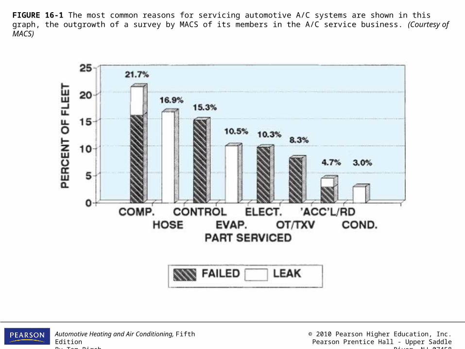
FIGURE 16-1 The most common reasons for servicing automotive A/C systems are shown in this graph, the outgrowth of a survey by MACS of its members in the A/C service business. (Courtesy of MACS)
Automotive Heating and Air Conditioning, Fifth EditionBy Tom Birch
© 2010 Pearson Higher Education, Inc.Pearson Prentice Hall - Upper Saddle River, NJ 07458
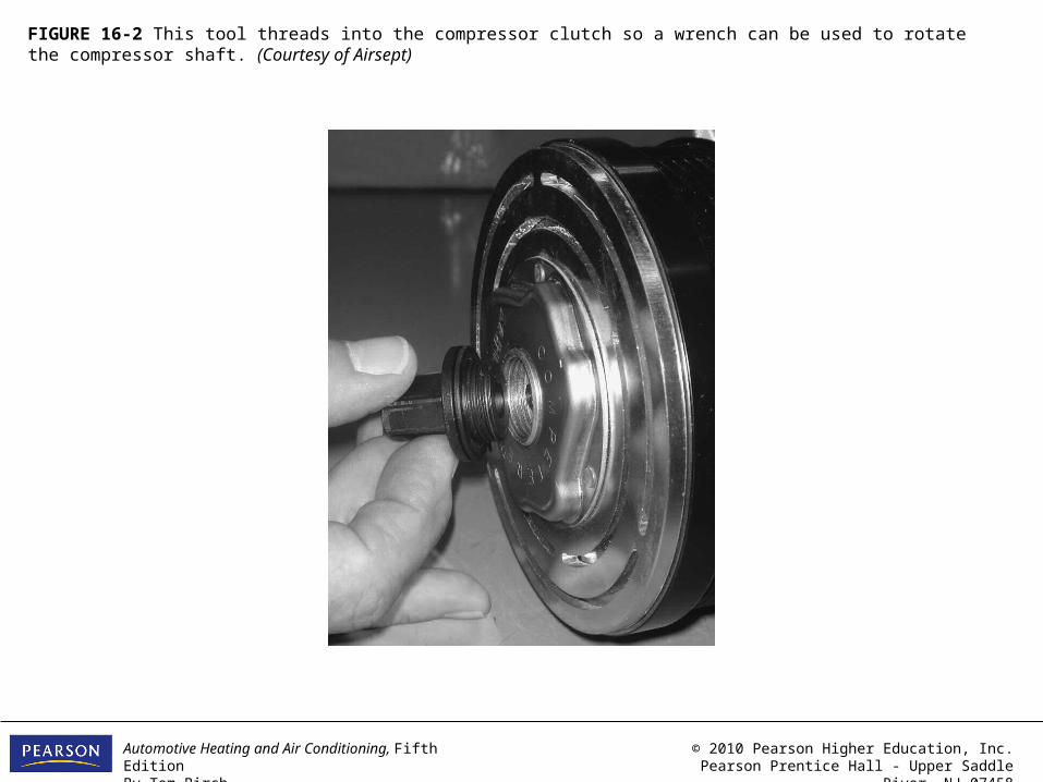
FIGURE 16-2 This tool threads into the compressor clutch so a wrench can be used to rotate the compressor shaft. (Courtesy of Airsept)

Automotive Heating and Air Conditioning, Fifth EditionBy Tom Birch
© 2010 Pearson Higher Education, Inc.Pearson Prentice Hall - Upper Saddle River, NJ 07458
FIGURE 16-3 This set contains the special tools needed to service the clutch and shaft seal of Ford FS-6 and Chrysler C-171 compressors. (Courtesy of Kent-Moore)
Automotive Heating and Air Conditioning, Fifth EditionBy Tom Birch
© 2010 Pearson Higher Education, Inc.Pearson Prentice Hall - Upper Saddle River, NJ 07458
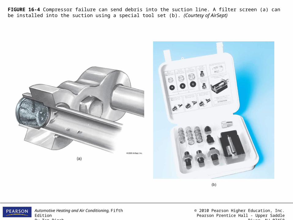
FIGURE 16-4 Compressor failure can send debris into the suction line. A filter screen (a) can be installed into the suction using a special tool set (b). (Courtesy of AirSept)
Automotive Heating and Air Conditioning, Fifth EditionBy Tom Birch
© 2010 Pearson Higher Education, Inc.Pearson Prentice Hall - Upper Saddle River, NJ 07458
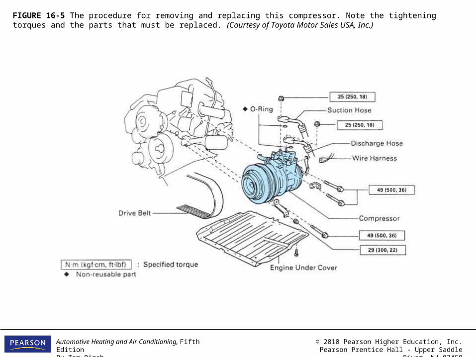
FIGURE 16-5 The procedure for removing and replacing this compressor. Note the tightening torques and the parts that must be replaced. (Courtesy of Toyota Motor Sales USA, Inc.)
Automotive Heating and Air Conditioning, Fifth EditionBy Tom Birch
© 2010 Pearson Higher Education, Inc.Pearson Prentice Hall - Upper Saddle River, NJ 07458
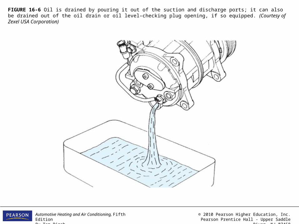
FIGURE 16-6 Oil is drained by pouring it out of the suction and discharge ports; it can also be drained out of the oil drain or oil level–checking plug opening, if so equipped. (Courtesy of Zexel USA Corporation)

Automotive Heating and Air Conditioning, Fifth EditionBy Tom Birch
© 2010 Pearson Higher Education, Inc.Pearson Prentice Hall - Upper Saddle River, NJ 07458
FIGURE 16-7 When replacing a clutch or pulley, check the type and size of the pulley belt grooves (a), the pulley diameter (b), and groove spacing (c) to make sure the replacement part is correct. (Courtesy of Warner Electric)
Automotive Heating and Air Conditioning, Fifth EditionBy Tom Birch
© 2010 Pearson Higher Education, Inc.Pearson Prentice Hall - Upper Saddle River, NJ 07458
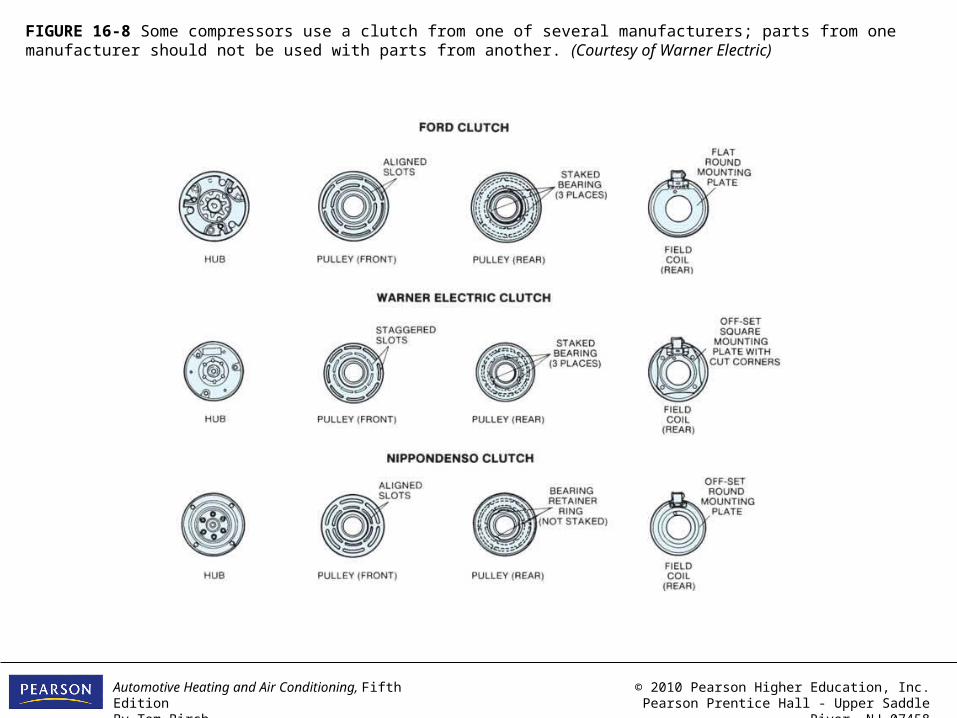
FIGURE 16-8 Some compressors use a clutch from one of several manufacturers; parts from one manufacturer should not be used with parts from another. (Courtesy of Warner Electric)

Automotive Heating and Air Conditioning, Fifth EditionBy Tom Birch
© 2010 Pearson Higher Education, Inc.Pearson Prentice Hall - Upper Saddle River, NJ 07458
FIGURE 16-9 The correct pulley being used with the correct field coil (left and center). A weak mismatch with possible rubbing occurs if the parts are switched (right). (Courtesy of Warner Electric)

Automotive Heating and Air Conditioning, Fifth EditionBy Tom Birch
© 2010 Pearson Higher Education, Inc.Pearson Prentice Hall - Upper Saddle River, NJ 07458
FIGURE 16-10 This clutch assembly is removed by removing the retaining nut (a), pulling the clutch plate (b), removing the pulley retaining ring (c), removing the pulley (d), and removing the coil retaining ring and the coil (e) and (f). Special pullers are often required to remove the plate, pulley, or coil. Courtesy of Chrysler LLC)
Automotive Heating and Air Conditioning, Fifth EditionBy Tom Birch
© 2010 Pearson Higher Education, Inc.Pearson Prentice Hall - Upper Saddle River, NJ 07458
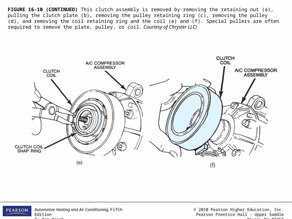
FIGURE 16-10 (CONTINUED) This clutch assembly is removed by removing the retaining nut (a), pulling the clutch plate (b), removing the pulley retaining ring (c), removing the pulley (d), and removing the coil retaining ring and the coil (e) and (f). Special pullers are often required to remove the plate, pulley, or coil. Courtesy of Chrysler LLC)
Automotive Heating and Air Conditioning, Fifth EditionBy Tom Birch
© 2010 Pearson Higher Education, Inc.Pearson Prentice Hall - Upper Saddle River, NJ 07458
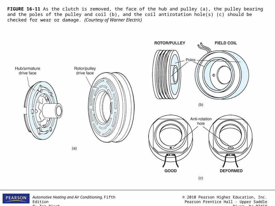
FIGURE 16-11 As the clutch is removed, the face of the hub and pulley (a), the pulley bearing and the poles of the pulley and coil (b), and the coil antirotation hole(s) (c) should be checked for wear or damage. (Courtesy of Warner Electric)
Automotive Heating and Air Conditioning, Fifth EditionBy Tom Birch
© 2010 Pearson Higher Education, Inc.Pearson Prentice Hall - Upper Saddle River, NJ 07458
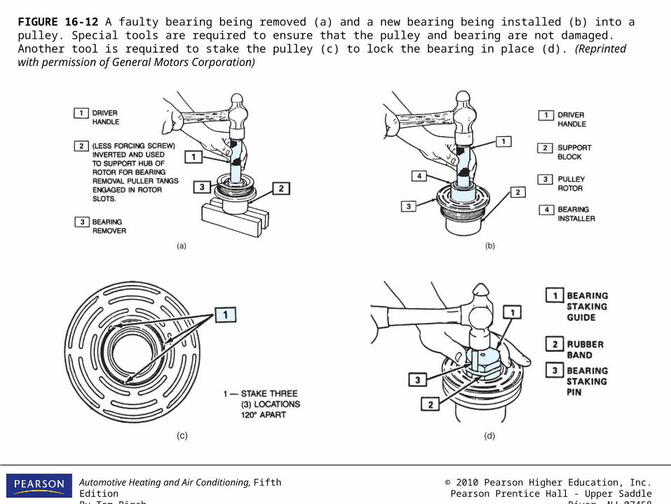
FIGURE 16-12 A faulty bearing being removed (a) and a new bearing being installed (b) into a pulley. Special tools are required to ensure that the pulley and bearing are not damaged. Another tool is required to stake the pulley (c) to lock the bearing in place (d). (Reprinted with permission of General Motors Corporation)
Automotive Heating and Air Conditioning, Fifth EditionBy Tom Birch
© 2010 Pearson Higher Education, Inc.Pearson Prentice Hall - Upper Saddle River, NJ 07458
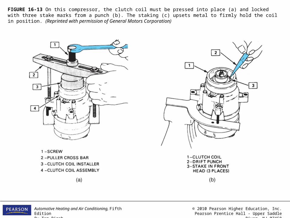
FIGURE 16-13 On this compressor, the clutch coil must be pressed into place (a) and locked with three stake marks from a punch (b). The staking (c) upsets metal to firmly hold the coil in position. (Reprinted with permission of General Motors Corporation)

Automotive Heating and Air Conditioning, Fifth EditionBy Tom Birch
© 2010 Pearson Higher Education, Inc.Pearson Prentice Hall - Upper Saddle River, NJ 07458
FIGURE 16-13 (CONTINUED) On this compressor, the clutch coil must be pressed into place (a) and locked with three stake marks from a punch (b). The staking (c) upsets metal to firmly hold the coil in position. (Reprinted with permission of General Motors Corporation)
Automotive Heating and Air Conditioning, Fifth EditionBy Tom Birch
© 2010 Pearson Higher Education, Inc.Pearson Prentice Hall - Upper Saddle River, NJ 07458
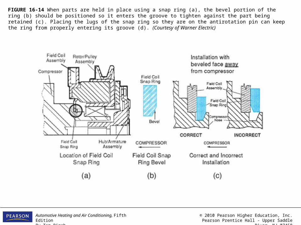
FIGURE 16-14 When parts are held in place using a snap ring (a), the bevel portion of the ring (b) should be positioned so it enters the groove to tighten against the part being retained (c). Placing the lugs of the snap ring so they are on the antirotation pin can keep the ring from properly entering its groove (d). (Courtesy of Warner Electric)

Automotive Heating and Air Conditioning, Fifth EditionBy Tom Birch
© 2010 Pearson Higher Education, Inc.Pearson Prentice Hall - Upper Saddle River, NJ 07458
FIGURE 16-14 (CONTINUED) When parts are held in place using a snap ring (a), the bevel portion of the ring (b) should be positioned so it enters the groove to tighten against the part being retained (c). Placing the lugs of the snap ring so they are on the antirotation pin can keep the ring from properly entering its groove (d). (Courtesy of Warner Electric)
Automotive Heating and Air Conditioning, Fifth EditionBy Tom Birch
© 2010 Pearson Higher Education, Inc.Pearson Prentice Hall - Upper Saddle River, NJ 07458
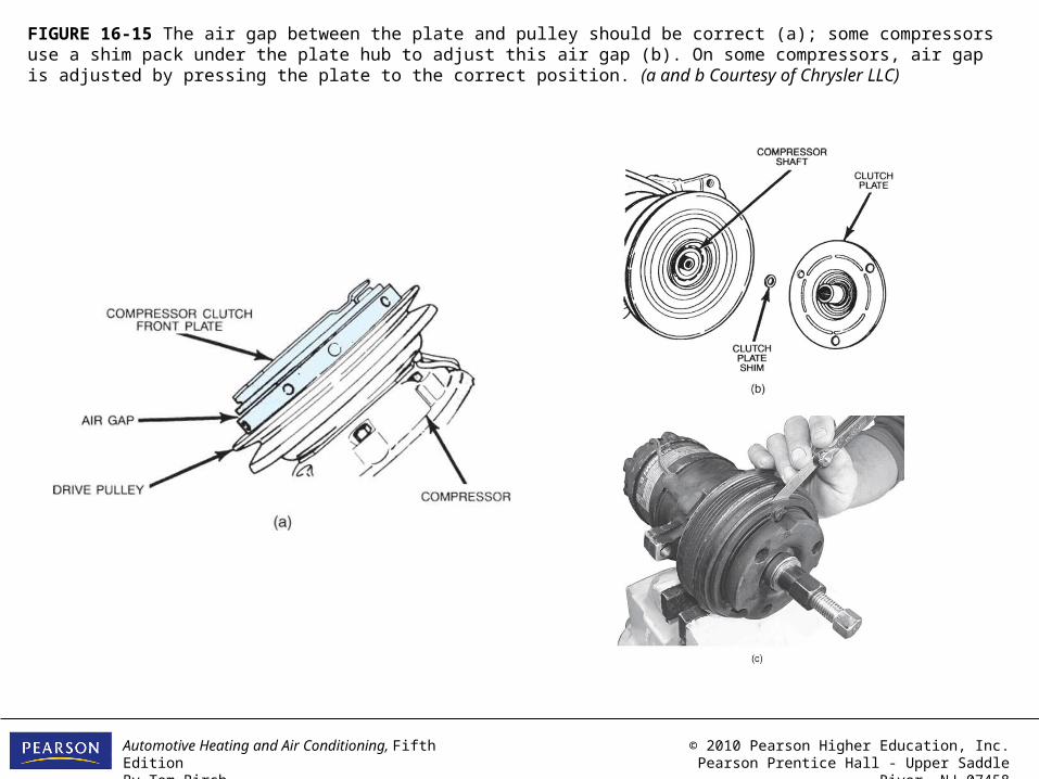
FIGURE 16-15 The air gap between the plate and pulley should be correct (a); some compressors use a shim pack under the plate hub to adjust this air gap (b). On some compressors, air gap is adjusted by pressing the plate to the correct position. (a and b Courtesy of Chrysler LLC)
Automotive Heating and Air Conditioning, Fifth EditionBy Tom Birch
© 2010 Pearson Higher Education, Inc.Pearson Prentice Hall - Upper Saddle River, NJ 07458
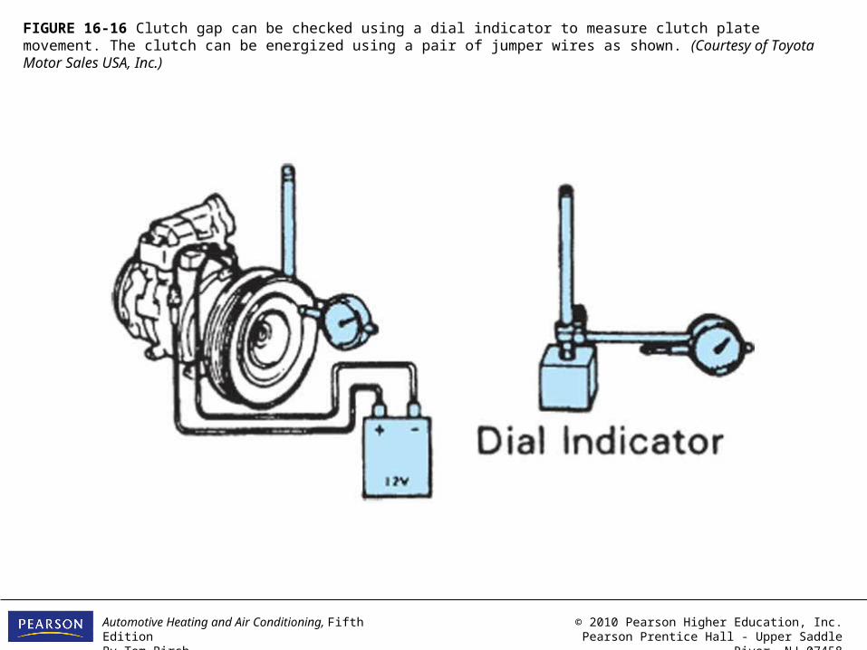
FIGURE 16-16 Clutch gap can be checked using a dial indicator to measure clutch plate movement. The clutch can be energized using a pair of jumper wires as shown. (Courtesy of Toyota Motor Sales USA, Inc.)
Automotive Heating and Air Conditioning, Fifth EditionBy Tom Birch
© 2010 Pearson Higher Education, Inc.Pearson Prentice Hall - Upper Saddle River, NJ 07458
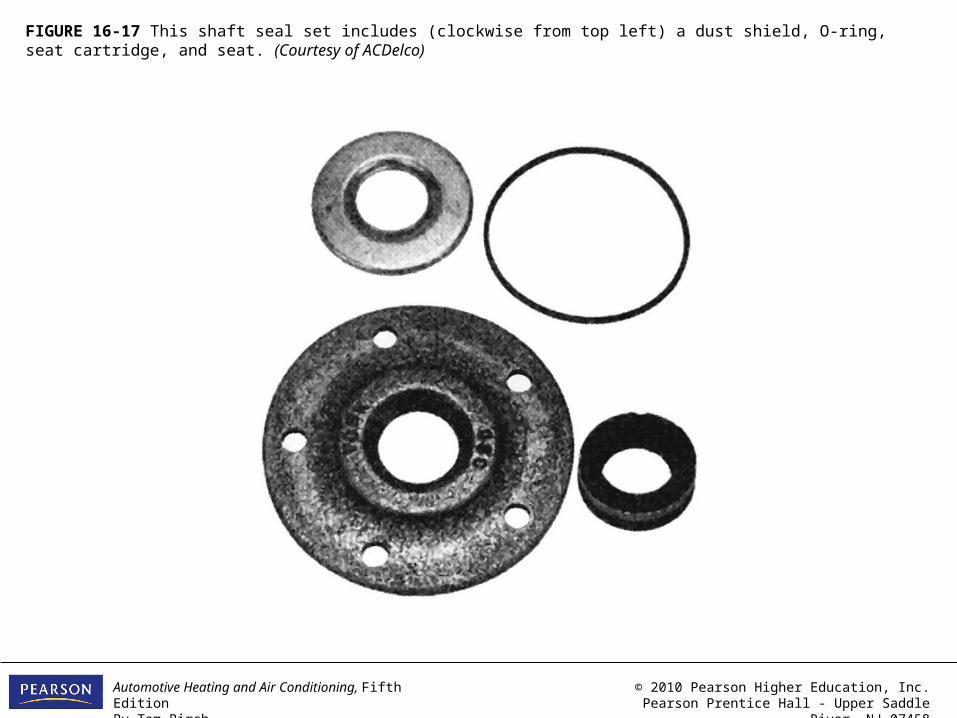
FIGURE 16-17 This shaft seal set includes (clockwise from top left) a dust shield, O-ring, seat cartridge, and seat. (Courtesy of ACDelco)
Automotive Heating and Air Conditioning, Fifth EditionBy Tom Birch
© 2010 Pearson Higher Education, Inc.Pearson Prentice Hall - Upper Saddle River, NJ 07458
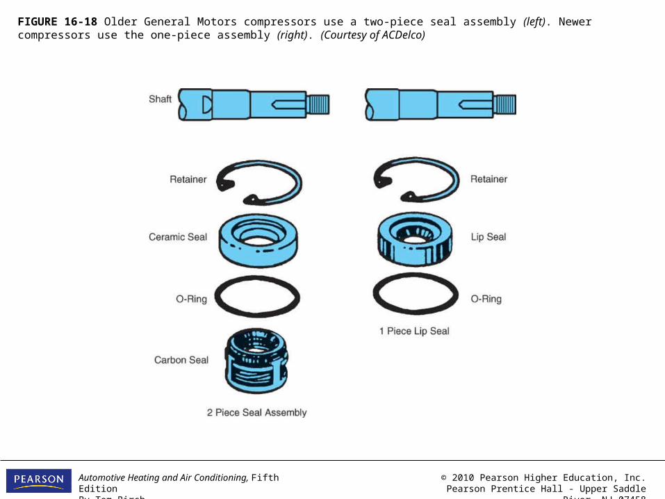
FIGURE 16-18 Older General Motors compressors use a two-piece seal assembly (left). Newer compressors use the one-piece assembly (right). (Courtesy of ACDelco)
Automotive Heating and Air Conditioning, Fifth EditionBy Tom Birch
© 2010 Pearson Higher Education, Inc.Pearson Prentice Hall - Upper Saddle River, NJ 07458
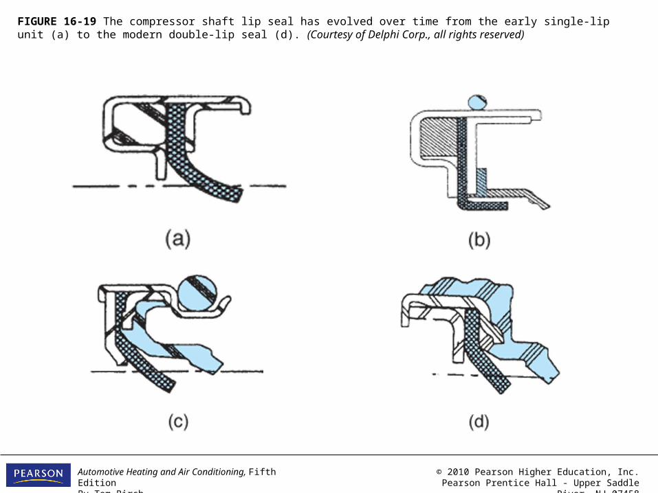
FIGURE 16-19 The compressor shaft lip seal has evolved over time from the early single-lip unit (a) to the modern double-lip seal (d). (Courtesy of Delphi Corp., all rights reserved)
Automotive Heating and Air Conditioning, Fifth EditionBy Tom Birch
© 2010 Pearson Higher Education, Inc.Pearson Prentice Hall - Upper Saddle River, NJ 07458
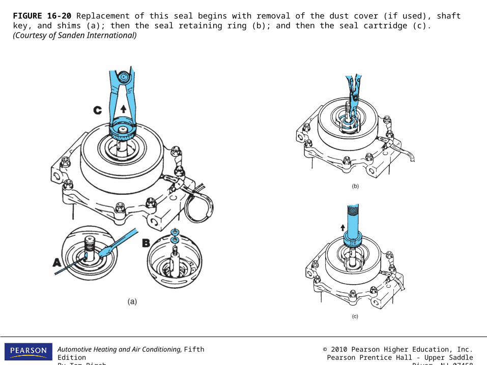
FIGURE 16-20 Replacement of this seal begins with removal of the dust cover (if used), shaft key, and shims (a); then the seal retaining ring (b); and then the seal cartridge (c). (Courtesy of Sanden International)

Automotive Heating and Air Conditioning, Fifth EditionBy Tom Birch
© 2010 Pearson Higher Education, Inc.Pearson Prentice Hall - Upper Saddle River, NJ 07458
FIGURE 16-21 A/C Lube & Seal is a premium mineral lubricant in an aerosol container. It is a convenient method of lubricating parts, O-rings, and fittings as they are assembled. (Courtesy of Technical Chemical Company, TCC)

Automotive Heating and Air Conditioning, Fifth EditionBy Tom Birch
© 2010 Pearson Higher Education, Inc.Pearson Prentice Hall - Upper Saddle River, NJ 07458
FIGURE 16-22 The seal is replaced by installing the O-ring using the installing tool (a), placing the seal on an installation tool, dipping it in clean refrigerant oil, and sliding it on to the compressor shaft (b); the retaining ring is installed (c); and then any other items taken out during the removal are replaced (d).(c and d are courtesy of Sanden International)
Automotive Heating and Air Conditioning, Fifth EditionBy Tom Birch
© 2010 Pearson Higher Education, Inc.Pearson Prentice Hall - Upper Saddle River, NJ 07458
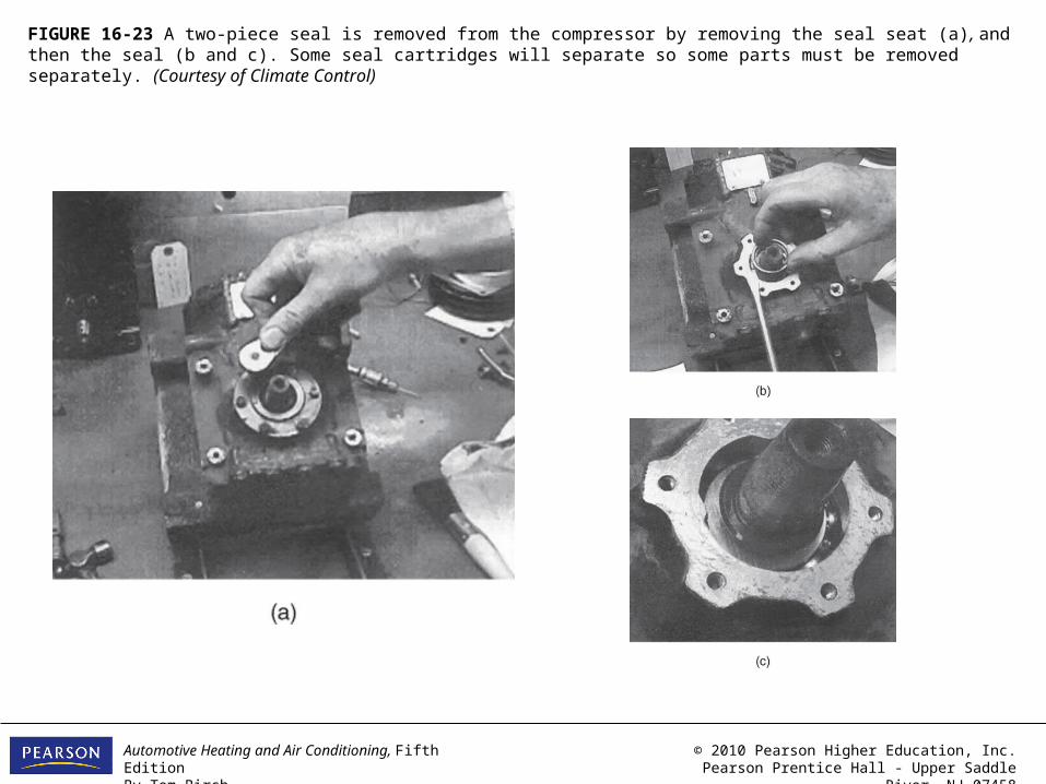
FIGURE 16-23 A two-piece seal is removed from the compressor by removing the seal seat (a), and then the seal (b and c). Some seal cartridges will separate so some parts must be removed separately. (Courtesy of Climate Control)

Automotive Heating and Air Conditioning, Fifth EditionBy Tom Birch
© 2010 Pearson Higher Education, Inc.Pearson Prentice Hall - Upper Saddle River, NJ 07458
FIGURE 16-24 The shaft seal of many Nippondenso-type compressors is inside the front head. The compressor must be partially disassembled in order to remove and replace the seal.
Automotive Heating and Air Conditioning, Fifth EditionBy Tom Birch
© 2010 Pearson Higher Education, Inc.Pearson Prentice Hall - Upper Saddle River, NJ 07458
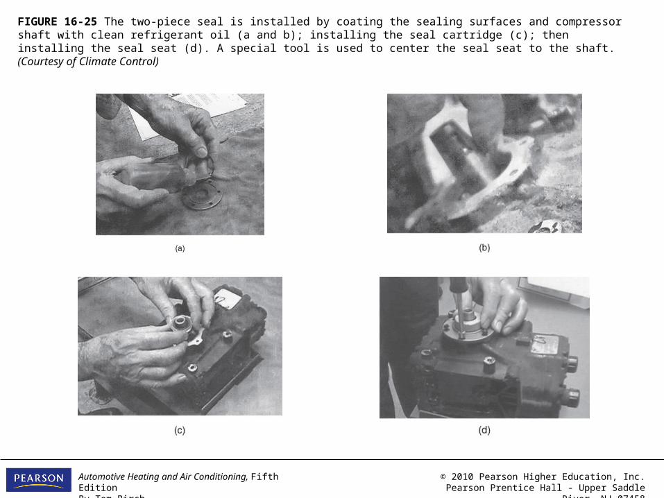
FIGURE 16-25 The two-piece seal is installed by coating the sealing surfaces and compressor shaft with clean refrigerant oil (a and b); installing the seal cartridge (c); then installing the seal seat (d). A special tool is used to center the seal seat to the shaft. (Courtesy of Climate Control)
Automotive Heating and Air Conditioning, Fifth EditionBy Tom Birch
© 2010 Pearson Higher Education, Inc.Pearson Prentice Hall - Upper Saddle River, NJ 07458
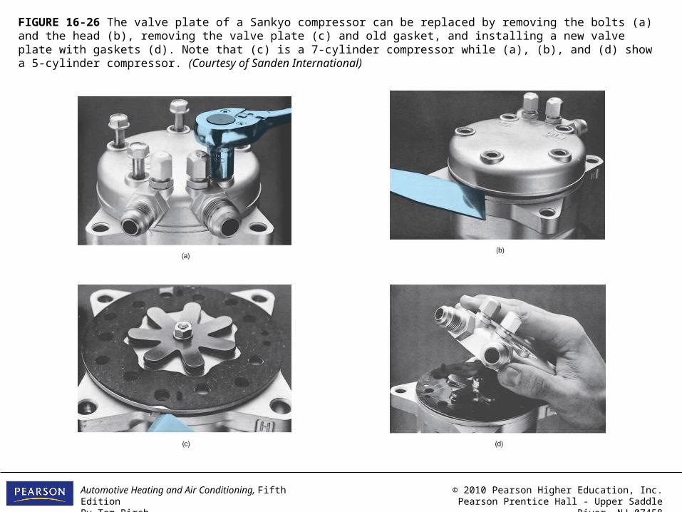
FIGURE 16-26 The valve plate of a Sankyo compressor can be replaced by removing the bolts (a) and the head (b), removing the valve plate (c) and old gasket, and installing a new valve plate with gaskets (d). Note that (c) is a 7-cylinder compressor while (a), (b), and (d) show a 5-cylinder compressor. (Courtesy of Sanden International)
Automotive Heating and Air Conditioning, Fifth EditionBy Tom Birch
© 2010 Pearson Higher Education, Inc.Pearson Prentice Hall - Upper Saddle River, NJ 07458
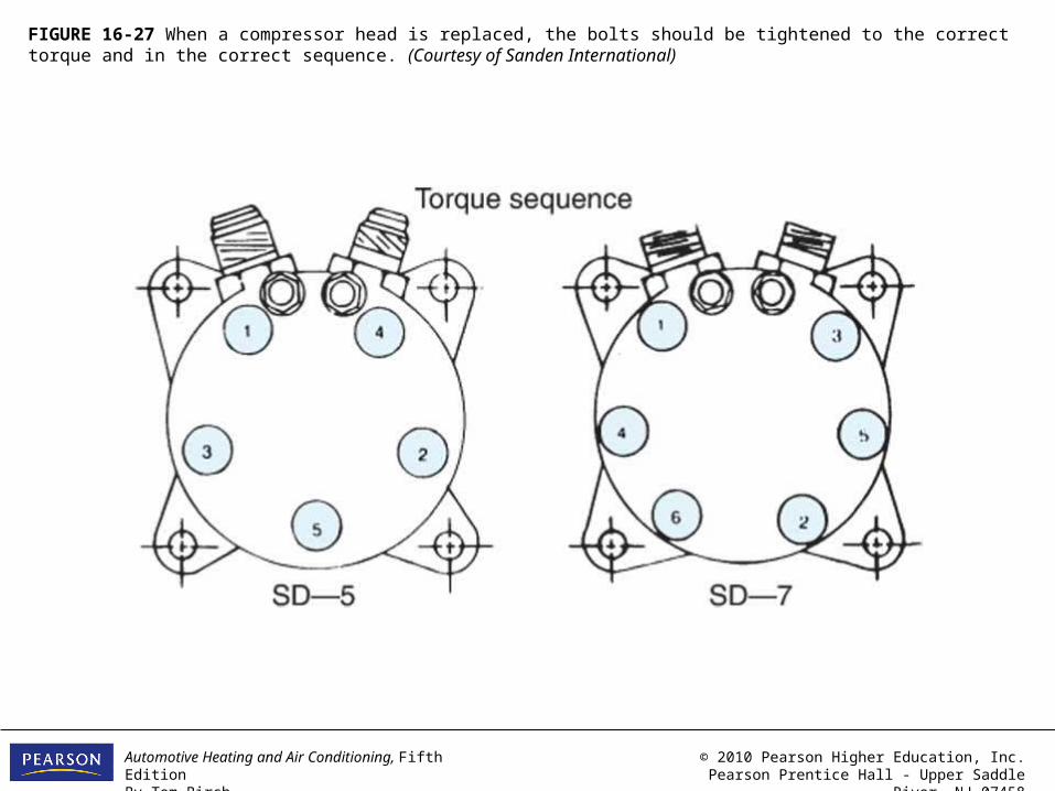
FIGURE 16-27 When a compressor head is replaced, the bolts should be tightened to the correct torque and in the correct sequence. (Courtesy of Sanden International)
Automotive Heating and Air Conditioning, Fifth EditionBy Tom Birch
© 2010 Pearson Higher Education, Inc.Pearson Prentice Hall - Upper Saddle River, NJ 07458
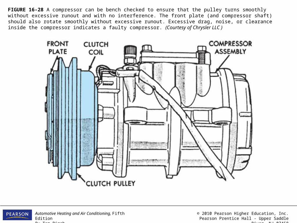
FIGURE 16-28 A compressor can be bench checked to ensure that the pulley turns smoothly without excessive runout and with no interference. The front plate (and compressor shaft) should also rotate smoothly without excessive runout. Excessive drag, noise, or clearance inside the compressor indicates a faulty compressor. (Courtesy of Chrysler LLC )

Automotive Heating and Air Conditioning, Fifth EditionBy Tom Birch
© 2010 Pearson Higher Education, Inc.Pearson Prentice Hall - Upper Saddle River, NJ 07458
FIGURE 16-29 If the compressor is equipped with service valves, it can be isolated from the system following this procedure.

Automotive Heating and Air Conditioning, Fifth EditionBy Tom Birch
© 2010 Pearson Higher Education, Inc.Pearson Prentice Hall - Upper Saddle River, NJ 07458
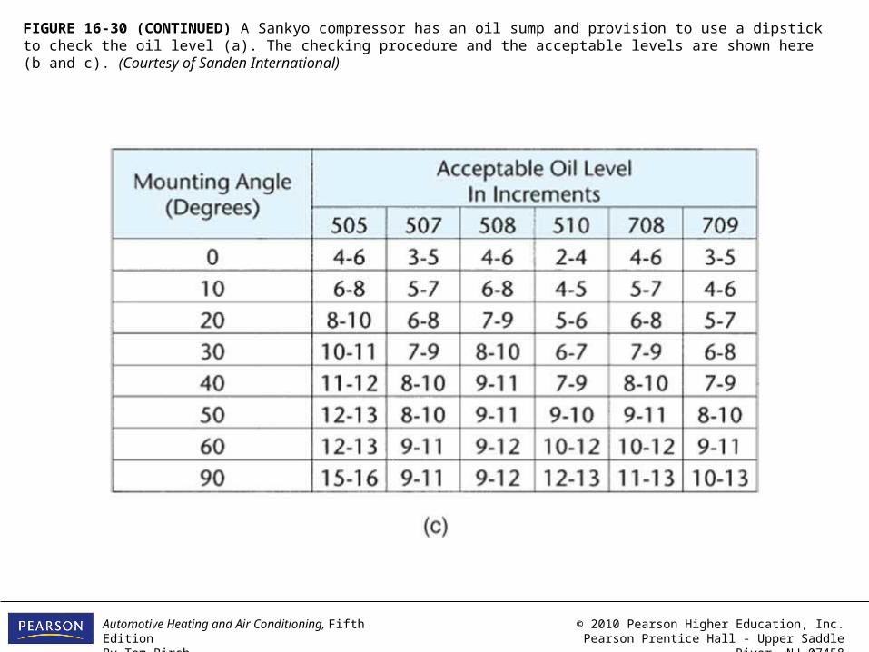
FIGURE 16-30 A Sankyo compressor has an oil sump and provision to use a dipstick to check the oil level (a). The checking procedure and the acceptable levels are shown here (b and c). (Courtesy of Sanden International)
Automotive Heating and Air Conditioning, Fifth EditionBy Tom Birch
© 2010 Pearson Higher Education, Inc.Pearson Prentice Hall - Upper Saddle River, NJ 07458
FIGURE 16-30 (CONTINUED) A Sankyo compressor has an oil sump and provision to use a dipstick to check the oil level (a). The checking procedure and the acceptable levels are shown here (b and c). (Courtesy of Sanden International)
Automotive Heating and Air Conditioning, Fifth EditionBy Tom Birch
© 2010 Pearson Higher Education, Inc.Pearson Prentice Hall - Upper Saddle River, NJ 07458
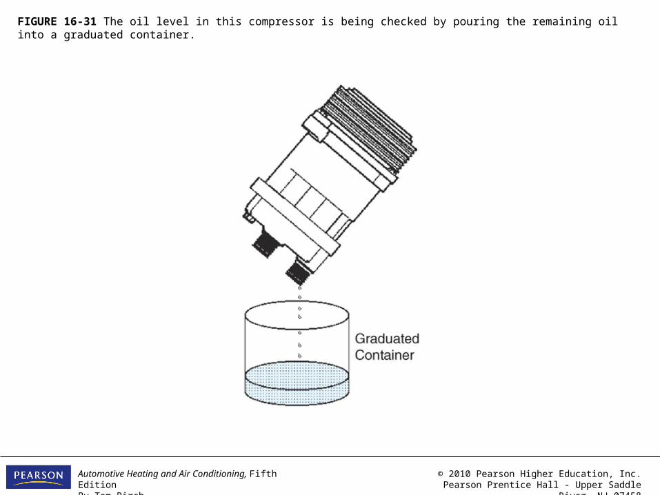
FIGURE 16-31 The oil level in this compressor is being checked by pouring the remaining oil into a graduated container.
Automotive Heating and Air Conditioning, Fifth EditionBy Tom Birch
© 2010 Pearson Higher Education, Inc.Pearson Prentice Hall - Upper Saddle River, NJ 07458
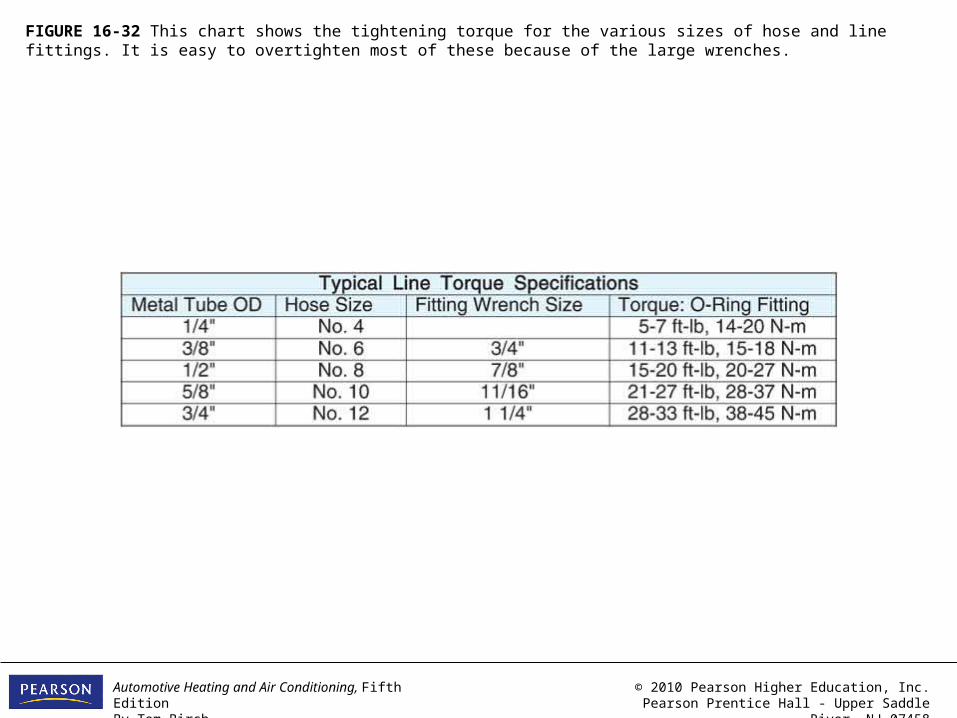
FIGURE 16-32 This chart shows the tightening torque for the various sizes of hose and line fittings. It is easy to overtighten most of these because of the large wrenches.
Automotive Heating and Air Conditioning, Fifth EditionBy Tom Birch
© 2010 Pearson Higher Education, Inc.Pearson Prentice Hall - Upper Saddle River, NJ 07458
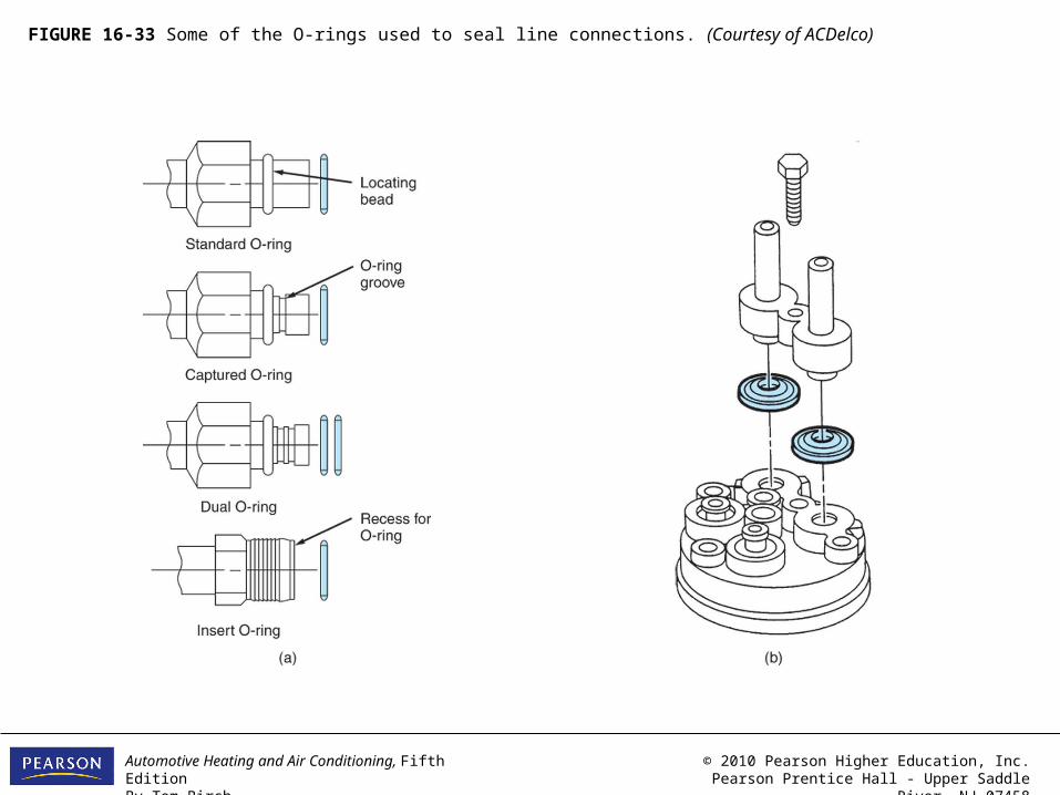
FIGURE 16-33 Some of the O-rings used to seal line connections. (Courtesy of ACDelco)

Automotive Heating and Air Conditioning, Fifth EditionBy Tom Birch
© 2010 Pearson Higher Education, Inc.Pearson Prentice Hall - Upper Saddle River, NJ 07458
FIGURE 16-34 When an O-ring is installed, it should be placed in its proper position next to the locating bead or in its groove. (Courtesy of Nissan Motor Corporation in USA)

Automotive Heating and Air Conditioning, Fifth EditionBy Tom Birch
© 2010 Pearson Higher Education, Inc.Pearson Prentice Hall - Upper Saddle River, NJ 07458
FIGURE 16-35 The O-ring must be wetted with ordinary refrigerant oil as it is installed. (Courtesy of Nissan Motor Corporation in USA)
Automotive Heating and Air Conditioning, Fifth EditionBy Tom Birch
© 2010 Pearson Higher Education, Inc.Pearson Prentice Hall - Upper Saddle River, NJ 07458
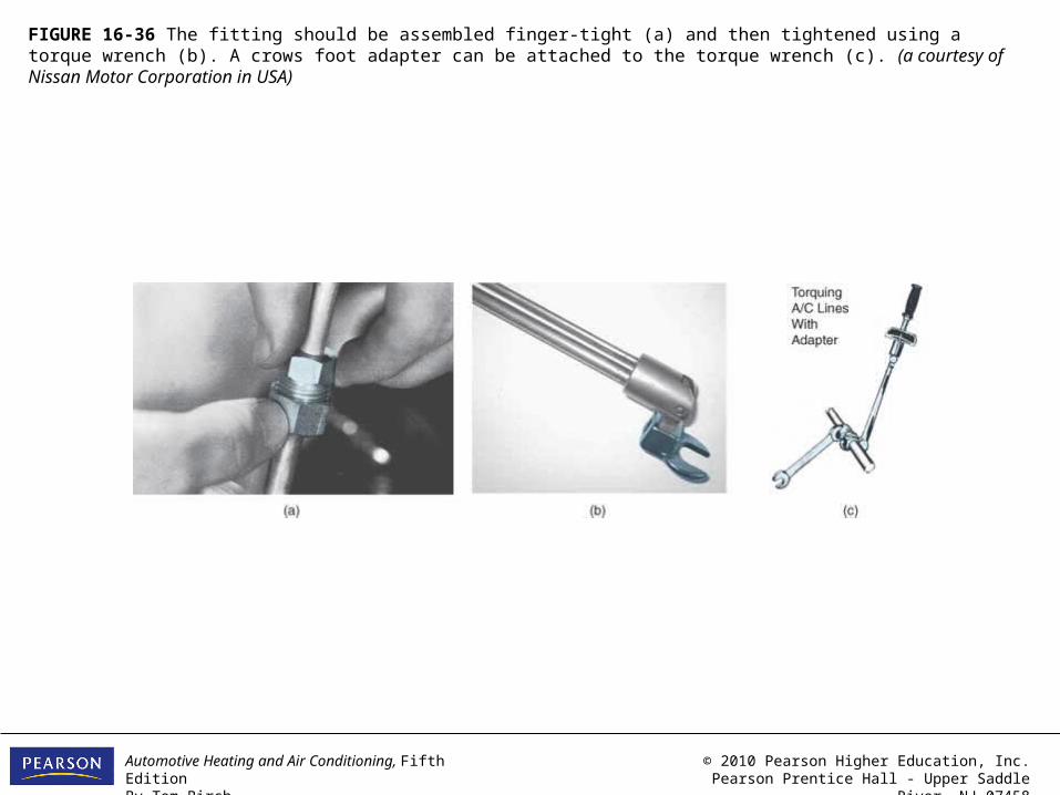
FIGURE 16-36 The fitting should be assembled finger-tight (a) and then tightened using a torque wrench (b). A crows foot adapter can be attached to the torque wrench (c). (a courtesy of Nissan Motor Corporation in USA)

Automotive Heating and Air Conditioning, Fifth EditionBy Tom Birch
© 2010 Pearson Higher Education, Inc.Pearson Prentice Hall - Upper Saddle River, NJ 07458
FIGURE 16-37 A frozen fitting nut can usually be loosened after drilling a hole into the nut using a No. 3 center drill bit and squirting penetrating oil into the threads.
Automotive Heating and Air Conditioning, Fifth EditionBy Tom Birch
© 2010 Pearson Higher Education, Inc.Pearson Prentice Hall - Upper Saddle River, NJ 07458
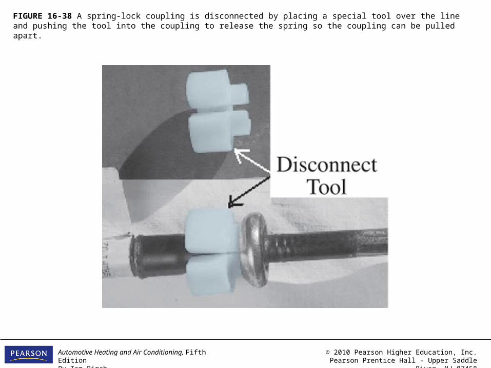
FIGURE 16-38 A spring-lock coupling is disconnected by placing a special tool over the line and pushing the tool into the coupling to release the spring so the coupling can be pulled apart.
Automotive Heating and Air Conditioning, Fifth EditionBy Tom Birch
© 2010 Pearson Higher Education, Inc.Pearson Prentice Hall - Upper Saddle River, NJ 07458
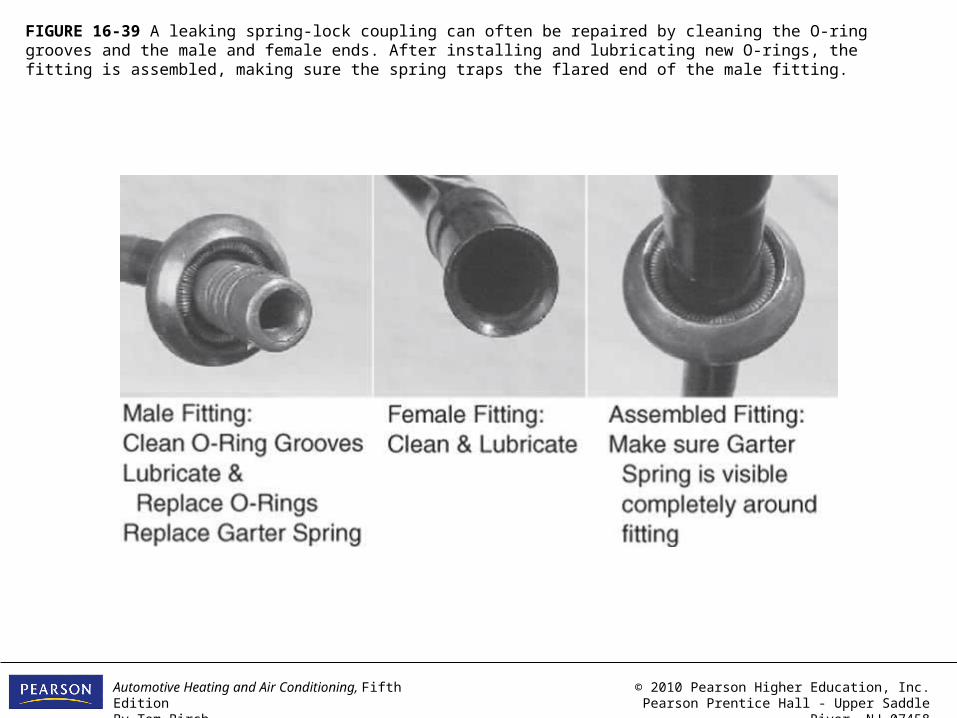
FIGURE 16-39 A leaking spring-lock coupling can often be repaired by cleaning the O-ring grooves and the male and female ends. After installing and lubricating new O-rings, the fitting is assembled, making sure the spring traps the flared end of the male fitting.

Automotive Heating and Air Conditioning, Fifth EditionBy Tom Birch
© 2010 Pearson Higher Education, Inc.Pearson Prentice Hall - Upper Saddle River, NJ 07458
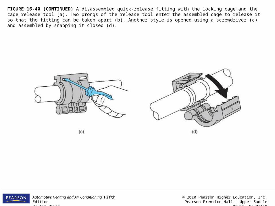
FIGURE 16-40 A disassembled quick-release fitting with the locking cage and the cage release tool (a). Two prongs of the release tool enter the assembled cage to release it so that the fitting can be taken apart (b). Another style is opened using a screwdriver (c) and assembled by snapping it closed (d).
Automotive Heating and Air Conditioning, Fifth EditionBy Tom Birch
© 2010 Pearson Higher Education, Inc.Pearson Prentice Hall - Upper Saddle River, NJ 07458
FIGURE 16-40 (CONTINUED) A disassembled quick-release fitting with the locking cage and the cage release tool (a). Two prongs of the release tool enter the assembled cage to release it so that the fitting can be taken apart (b). Another style is opened using a screwdriver (c) and assembled by snapping it closed (d).
Automotive Heating and Air Conditioning, Fifth EditionBy Tom Birch
© 2010 Pearson Higher Education, Inc.Pearson Prentice Hall - Upper Saddle River, NJ 07458
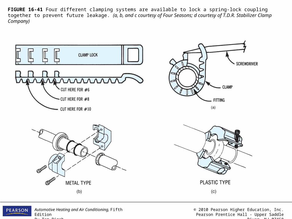
FIGURE 16-41 Four different clamping systems are available to lock a spring-lock coupling together to prevent future leakage. (a, b, and c courtesy of Four Seasons; d courtesy of T.D.R. Stabilizer Clamp Company)
Automotive Heating and Air Conditioning, Fifth EditionBy Tom Birch
© 2010 Pearson Higher Education, Inc.Pearson Prentice Hall - Upper Saddle River, NJ 07458
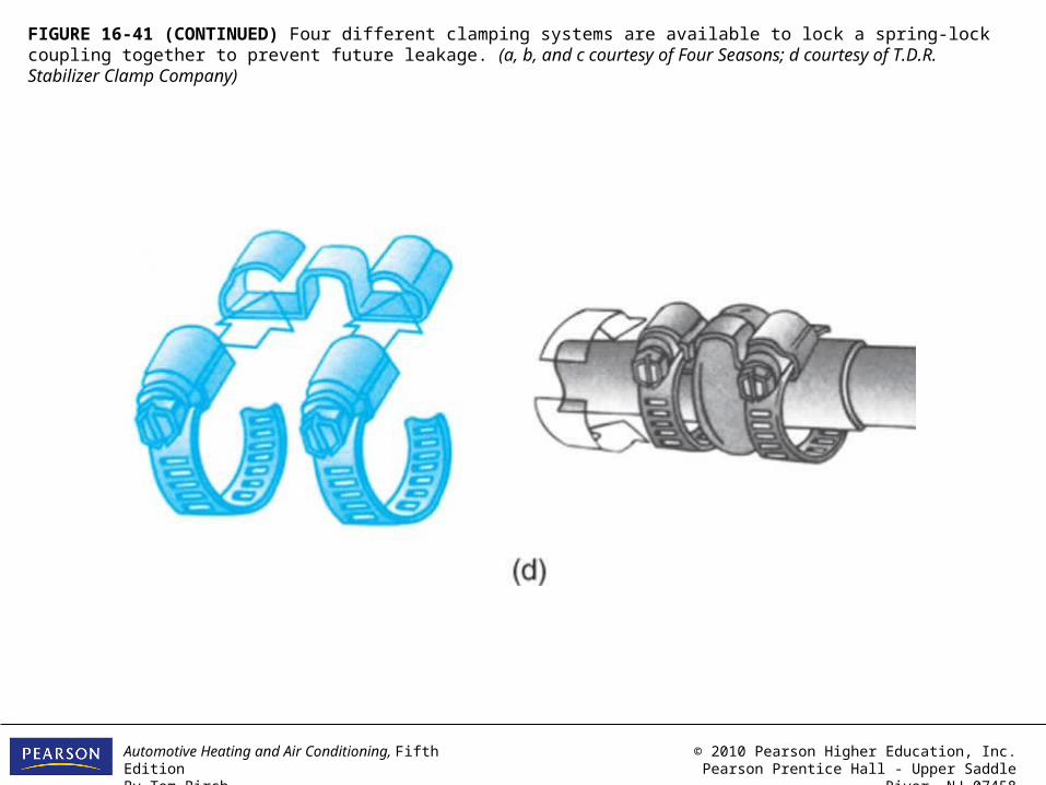
FIGURE 16-41 (CONTINUED) Four different clamping systems are available to lock a spring-lock coupling together to prevent future leakage. (a, b, and c courtesy of Four Seasons; d courtesy of T.D.R. Stabilizer Clamp Company)
Automotive Heating and Air Conditioning, Fifth EditionBy Tom Birch
© 2010 Pearson Higher Education, Inc.Pearson Prentice Hall - Upper Saddle River, NJ 07458
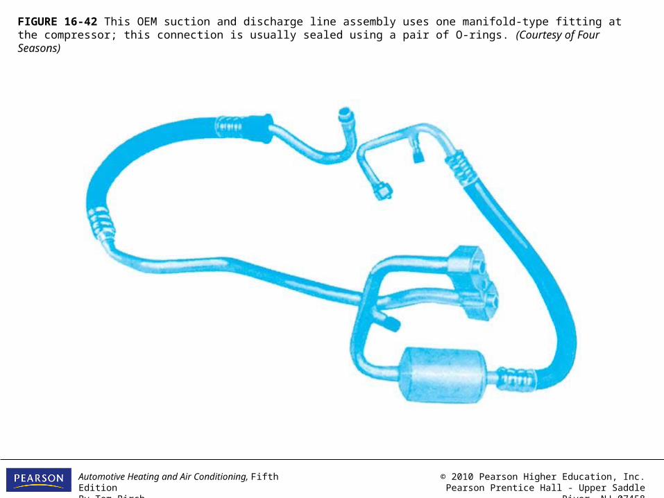
FIGURE 16-42 This OEM suction and discharge line assembly uses one manifold-type fitting at the compressor; this connection is usually sealed using a pair of O-rings. (Courtesy of Four Seasons)
Automotive Heating and Air Conditioning, Fifth EditionBy Tom Birch
© 2010 Pearson Higher Education, Inc.Pearson Prentice Hall - Upper Saddle River, NJ 07458
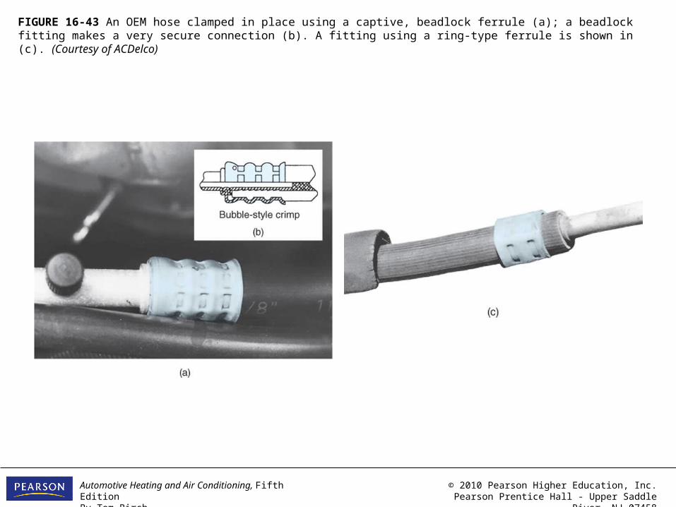
FIGURE 16-43 An OEM hose clamped in place using a captive, beadlock ferrule (a); a beadlock fitting makes a very secure connection (b). A fitting using a ring-type ferrule is shown in (c). (Courtesy of ACDelco)
Automotive Heating and Air Conditioning, Fifth EditionBy Tom Birch
© 2010 Pearson Higher Education, Inc.Pearson Prentice Hall - Upper Saddle River, NJ 07458
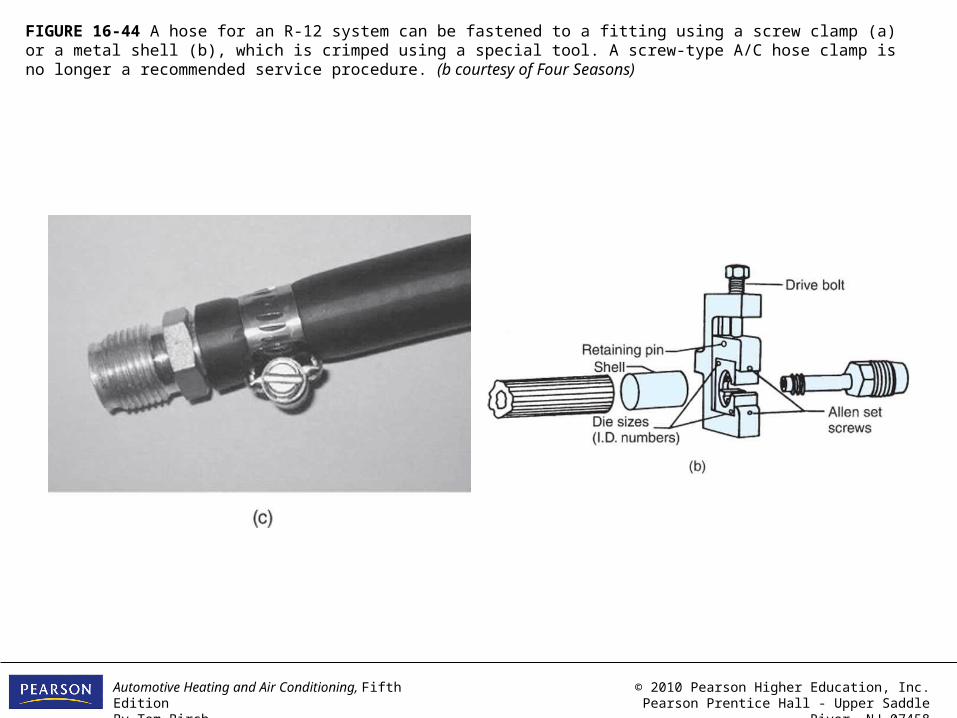
FIGURE 16-44 A hose for an R-12 system can be fastened to a fitting using a screw clamp (a) or a metal shell (b), which is crimped using a special tool. A screw-type A/C hose clamp is no longer a recommended service procedure. (b courtesy of Four Seasons)
Automotive Heating and Air Conditioning, Fifth EditionBy Tom Birch
© 2010 Pearson Higher Education, Inc.Pearson Prentice Hall - Upper Saddle River, NJ 07458
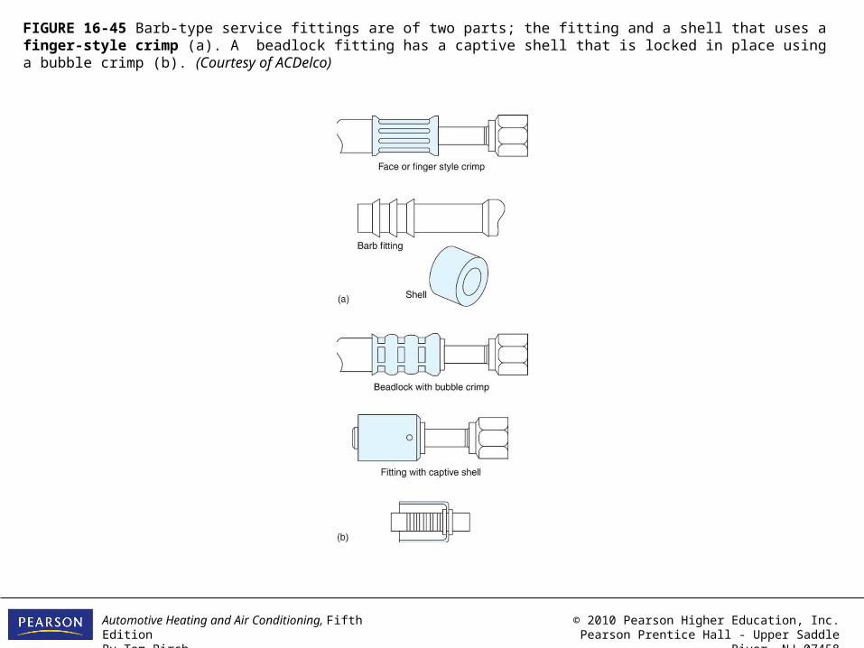
FIGURE 16-45 Barb-type service fittings are of two parts; the fitting and a shell that uses a finger-style crimp (a). A beadlock fitting has a captive shell that is locked in place using a bubble crimp (b). (Courtesy of ACDelco)
Automotive Heating and Air Conditioning, Fifth EditionBy Tom Birch
© 2010 Pearson Higher Education, Inc.Pearson Prentice Hall - Upper Saddle River, NJ 07458
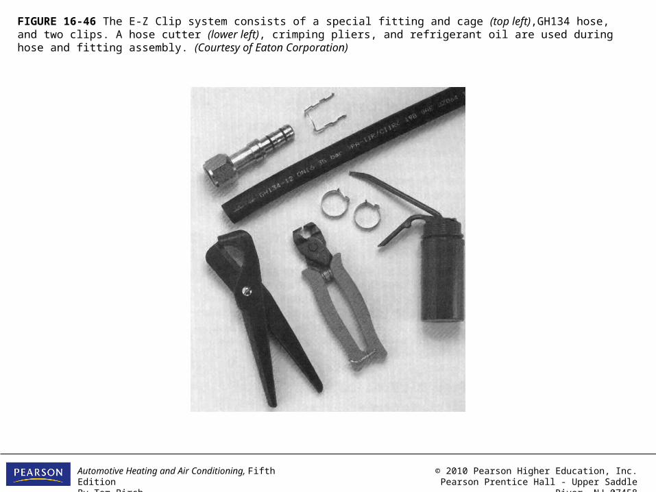
FIGURE 16-46 The E-Z Clip system consists of a special fitting and cage (top left),GH134 hose, and two clips. A hose cutter (lower left), crimping pliers, and refrigerant oil are used during hose and fitting assembly. (Courtesy of Eaton Corporation)

Automotive Heating and Air Conditioning, Fifth EditionBy Tom Birch
© 2010 Pearson Higher Education, Inc.Pearson Prentice Hall - Upper Saddle River, NJ 07458
FIGURE 16-47 Most replacement hose fittings match the hose ID to a particular tube and nut diameter.

Automotive Heating and Air Conditioning, Fifth EditionBy Tom Birch
© 2010 Pearson Higher Education, Inc.Pearson Prentice Hall - Upper Saddle River, NJ 07458
FIGURE 16-48 The stem section of beadlock and barb fittings matches the hose ID. (Courtesy of Four Seasons)
Automotive Heating and Air Conditioning, Fifth EditionBy Tom Birch
© 2010 Pearson Higher Education, Inc.Pearson Prentice Hall - Upper Saddle River, NJ 07458
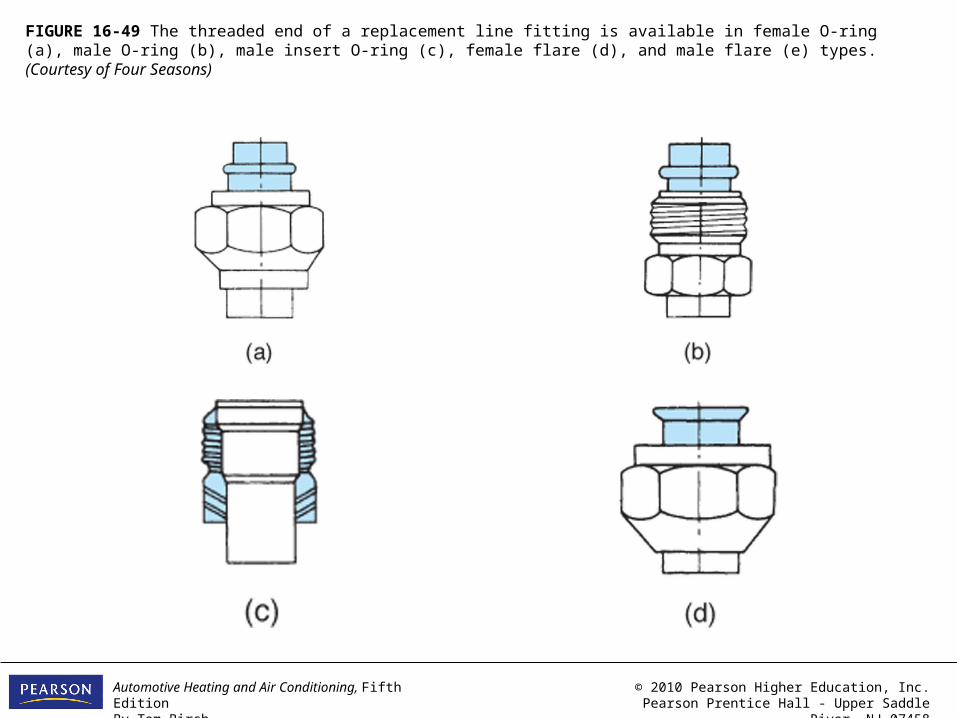
FIGURE 16-49 The threaded end of a replacement line fitting is available in female O-ring (a), male O-ring (b), male insert O-ring (c), female flare (d), and male flare (e) types. (Courtesy of Four Seasons)

Automotive Heating and Air Conditioning, Fifth EditionBy Tom Birch
© 2010 Pearson Higher Education, Inc.Pearson Prentice Hall - Upper Saddle River, NJ 07458
FIGURE 16-49 (CONTINUED) The threaded end of a replacement line fitting is available in female O-ring (a), male O-ring (b), male insert O-ring (c), female flare (d), and male flare (e) types. (Courtesy of Four Seasons)
Automotive Heating and Air Conditioning, Fifth EditionBy Tom Birch
© 2010 Pearson Higher Education, Inc.Pearson Prentice Hall - Upper Saddle River, NJ 07458
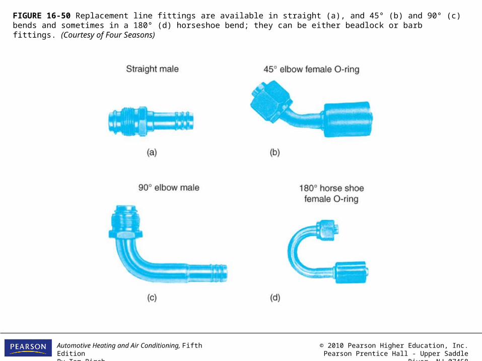
FIGURE 16-50 Replacement line fittings are available in straight (a), and 45° (b) and 90° (c) bends and sometimes in a 180° (d) horseshoe bend; they can be either beadlock or barb fittings. (Courtesy of Four Seasons)

Automotive Heating and Air Conditioning, Fifth EditionBy Tom Birch
© 2010 Pearson Higher Education, Inc.Pearson Prentice Hall - Upper Saddle River, NJ 07458
FIGURE 16-51 These two special fittings are used to connect a hose to a GM compressor. (Courtesy of Four Seasons)
Automotive Heating and Air Conditioning, Fifth EditionBy Tom Birch
© 2010 Pearson Higher Education, Inc.Pearson Prentice Hall - Upper Saddle River, NJ 07458
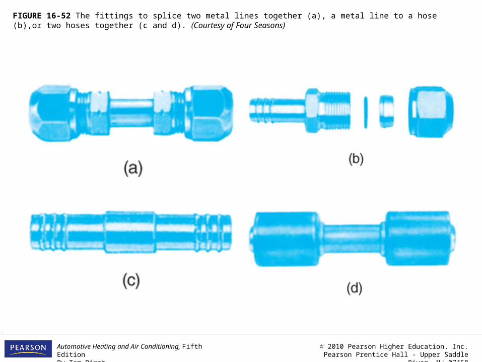
FIGURE 16-52 The fittings to splice two metal lines together (a), a metal line to a hose (b),or two hoses together (c and d). (Courtesy of Four Seasons)

Automotive Heating and Air Conditioning, Fifth EditionBy Tom Birch
© 2010 Pearson Higher Education, Inc.Pearson Prentice Hall - Upper Saddle River, NJ 07458
FIGURE 16-53 A Lokring fitting can be used to splice two metal lines or a fitting to a line. (Courtesy of American Lokring)
Automotive Heating and Air Conditioning, Fifth EditionBy Tom Birch
© 2010 Pearson Higher Education, Inc.Pearson Prentice Hall - Upper Saddle River, NJ 07458
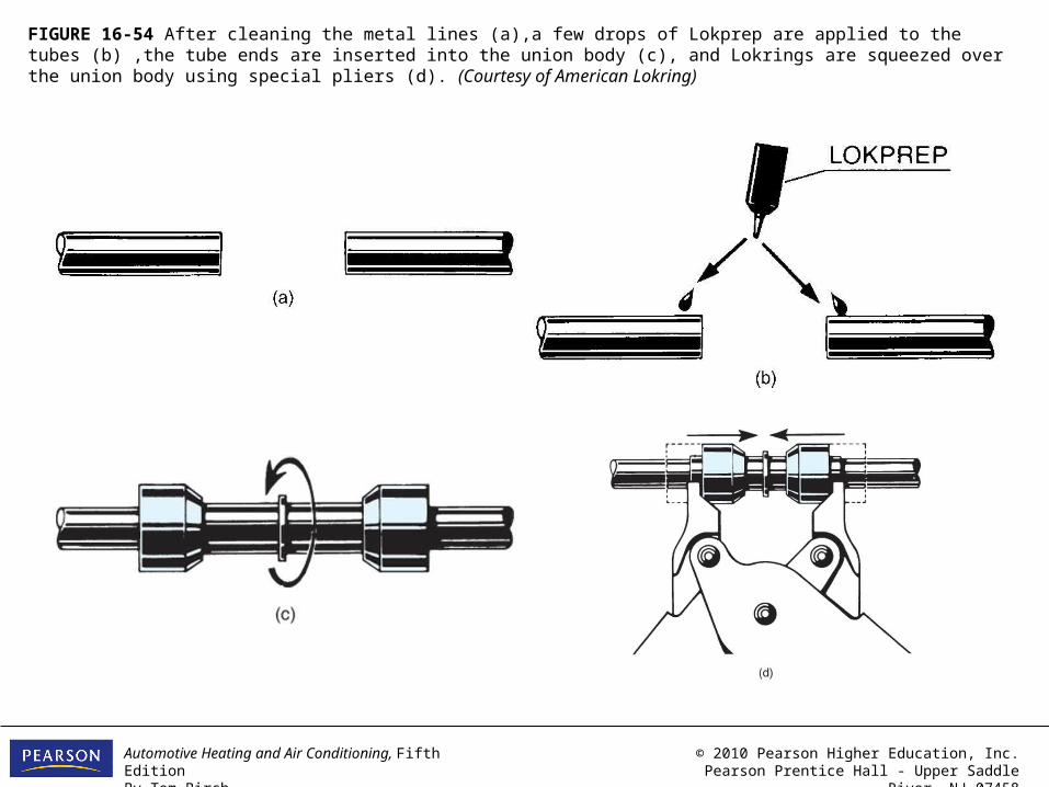
FIGURE 16-54 After cleaning the metal lines (a),a few drops of Lokprep are applied to the tubes (b) ,the tube ends are inserted into the union body (c), and Lokrings are squeezed over the union body using special pliers (d). (Courtesy of American Lokring)
Automotive Heating and Air Conditioning, Fifth EditionBy Tom Birch
© 2010 Pearson Higher Education, Inc.Pearson Prentice Hall - Upper Saddle River, NJ 07458
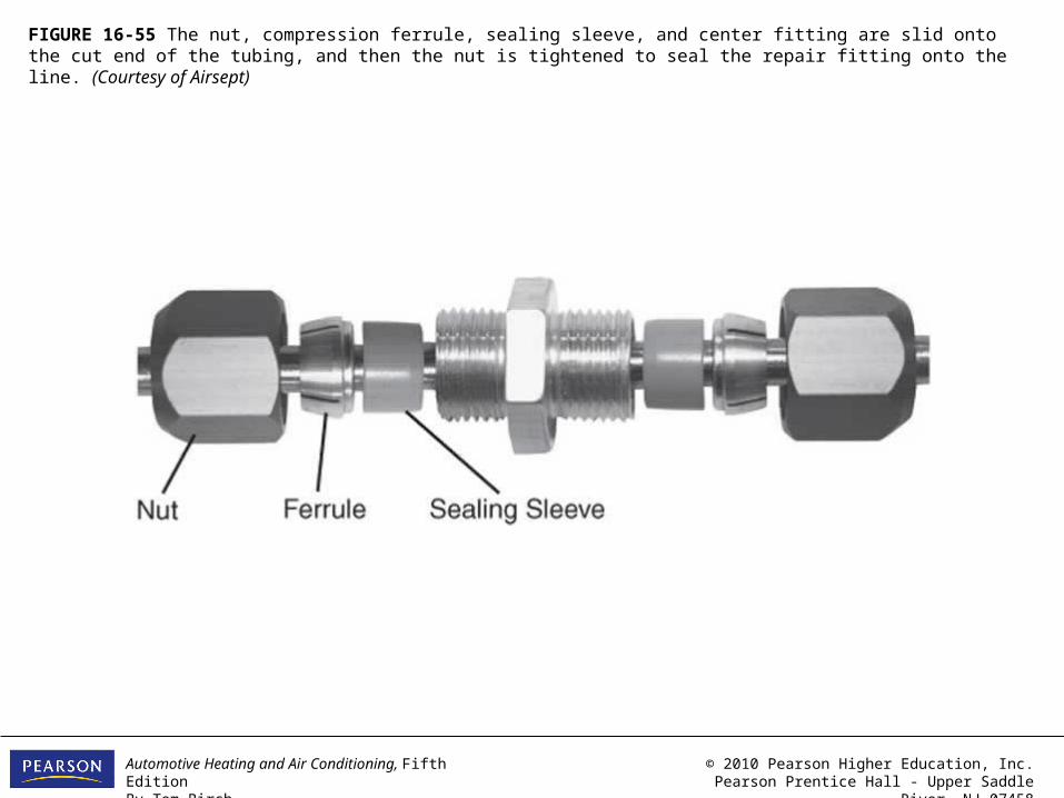
FIGURE 16-55 The nut, compression ferrule, sealing sleeve, and center fitting are slid onto the cut end of the tubing, and then the nut is tightened to seal the repair fitting onto the line. (Courtesy of Airsept)
Automotive Heating and Air Conditioning, Fifth EditionBy Tom Birch
© 2010 Pearson Higher Education, Inc.Pearson Prentice Hall - Upper Saddle River, NJ 07458
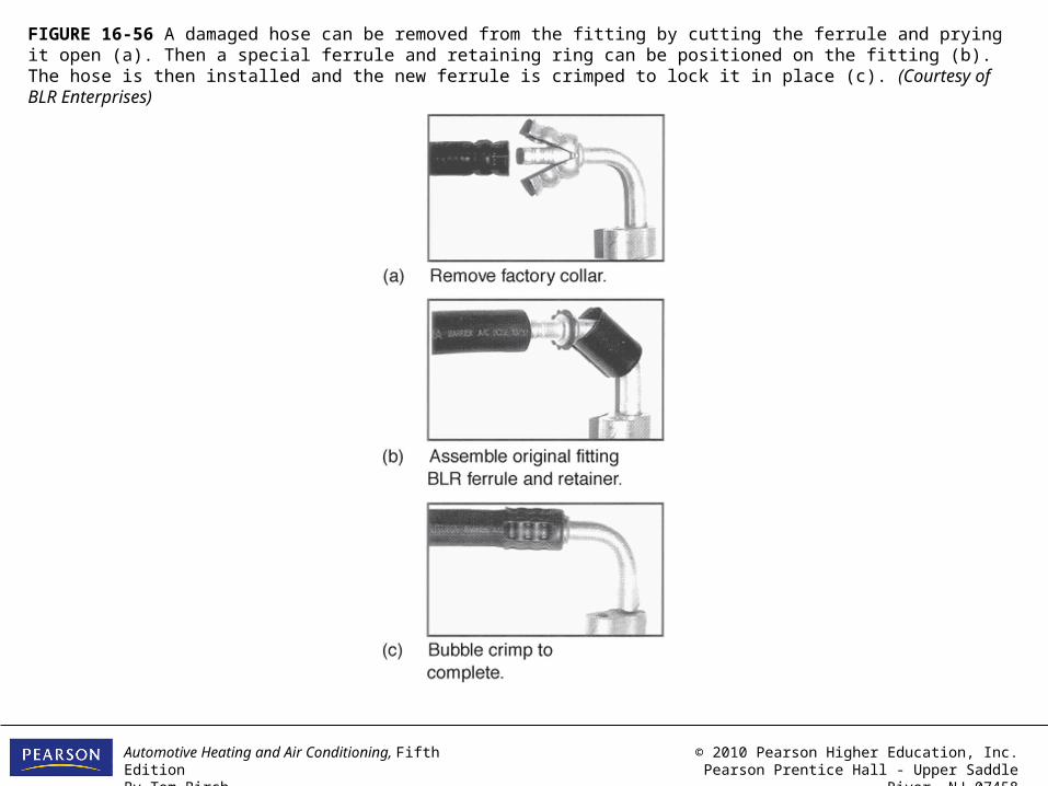
FIGURE 16-56 A damaged hose can be removed from the fitting by cutting the ferrule and prying it open (a). Then a special ferrule and retaining ring can be positioned on the fitting (b). The hose is then installed and the new ferrule is crimped to lock it in place (c). (Courtesy of BLR Enterprises)

Automotive Heating and Air Conditioning, Fifth EditionBy Tom Birch
© 2010 Pearson Higher Education, Inc.Pearson Prentice Hall - Upper Saddle River, NJ 07458
FIGURE 16-57 Refrigerant hose can be cut with a special cutter (a) or a sharp knife (b). (a courtesy of Four Seasons)

Automotive Heating and Air Conditioning, Fifth EditionBy Tom Birch
© 2010 Pearson Higher Education, Inc.Pearson Prentice Hall - Upper Saddle River, NJ 07458
FIGURE 16-58 When making a finger-style crimp on the metal shell, dies of the correct size are installed in the tool (a) and the shell is crimped by tightening the tool drive bolt (b). A finished installation is shown in (c). A bubble crimp is made using different crimp dies (d). (Courtesy of Four Seasons)
Automotive Heating and Air Conditioning, Fifth EditionBy Tom Birch
© 2010 Pearson Higher Education, Inc.Pearson Prentice Hall - Upper Saddle River, NJ 07458
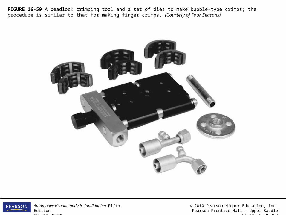
FIGURE 16-59 A beadlock crimping tool and a set of dies to make bubble-type crimps; the procedure is similar to that for making finger crimps. (Courtesy of Four Seasons)
Automotive Heating and Air Conditioning, Fifth EditionBy Tom Birch
© 2010 Pearson Higher Education, Inc.Pearson Prentice Hall - Upper Saddle River, NJ 07458
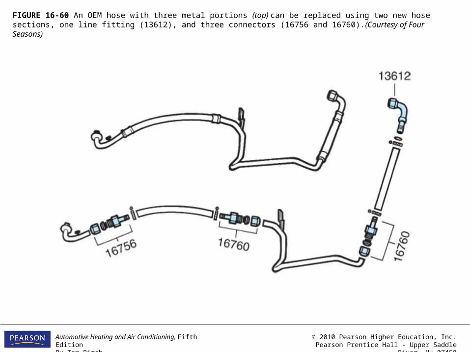
FIGURE 16-60 An OEM hose with three metal portions (top) can be replaced using two new hose sections, one line fitting (13612), and three connectors (16756 and 16760).(Courtesy of Four Seasons)
Automotive Heating and Air Conditioning, Fifth EditionBy Tom Birch
© 2010 Pearson Higher Education, Inc.Pearson Prentice Hall - Upper Saddle River, NJ 07458
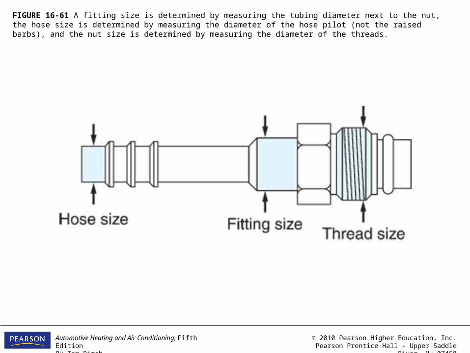
FIGURE 16-61 A fitting size is determined by measuring the tubing diameter next to the nut, the hose size is determined by measuring the diameter of the hose pilot (not the raised barbs), and the nut size is determined by measuring the diameter of the threads.
Automotive Heating and Air Conditioning, Fifth EditionBy Tom Birch
© 2010 Pearson Higher Education, Inc.Pearson Prentice Hall - Upper Saddle River, NJ 07458
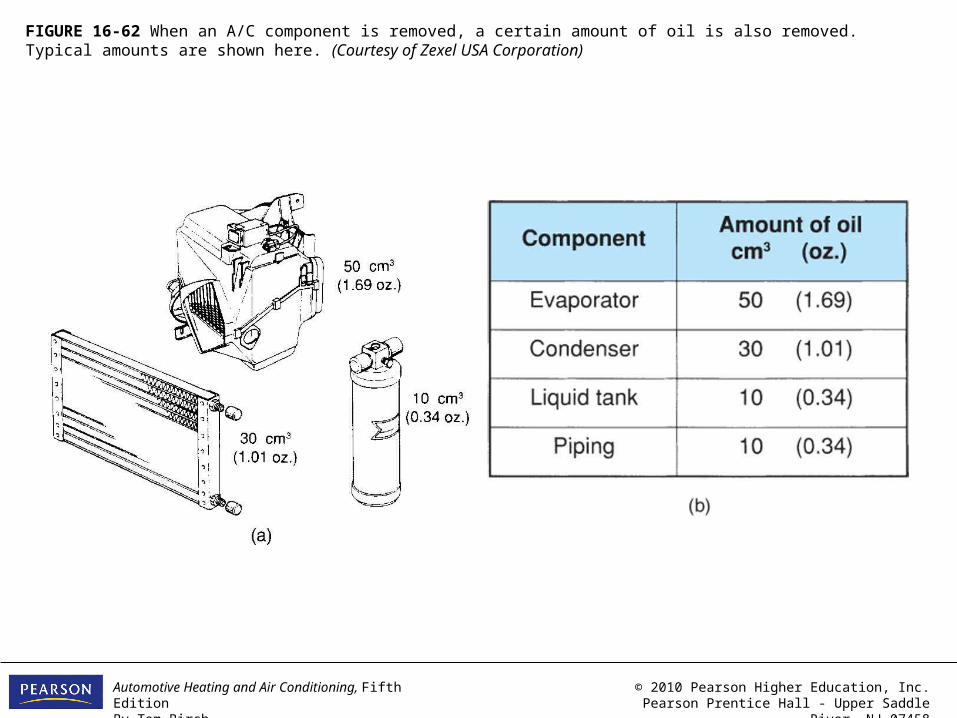
FIGURE 16-62 When an A/C component is removed, a certain amount of oil is also removed. Typical amounts are shown here. (Courtesy of Zexel USA Corporation)

Automotive Heating and Air Conditioning, Fifth EditionBy Tom Birch
© 2010 Pearson Higher Education, Inc.Pearson Prentice Hall - Upper Saddle River, NJ 07458
FIGURE 16-63 When an A/C component is replaced, the mounting brackets (a) and line fittings (b) should be replaced in the proper manner. (Provided courtesy of Toyota Motor Sales USA, Inc.)
Automotive Heating and Air Conditioning, Fifth EditionBy Tom Birch
© 2010 Pearson Higher Education, Inc.Pearson Prentice Hall - Upper Saddle River, NJ 07458
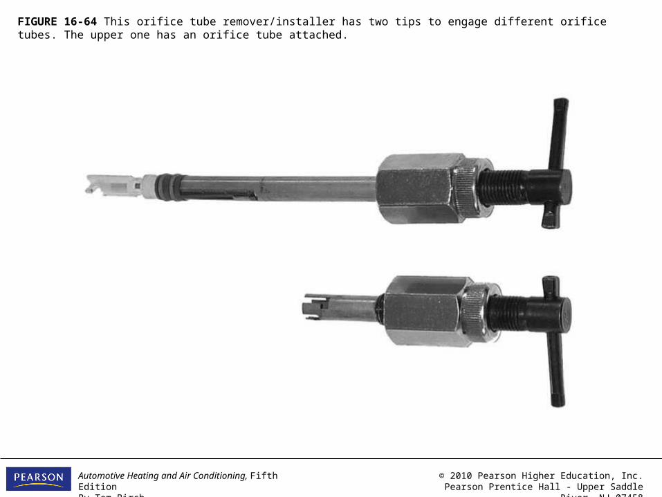
FIGURE 16-64 This orifice tube remover/installer has two tips to engage different orifice tubes. The upper one has an orifice tube attached.
Automotive Heating and Air Conditioning, Fifth EditionBy Tom Birch
© 2010 Pearson Higher Education, Inc.Pearson Prentice Hall - Upper Saddle River, NJ 07458
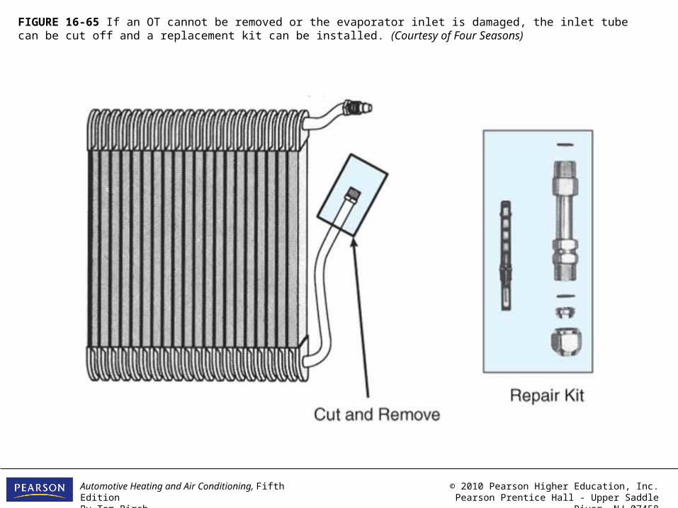
FIGURE 16-65 If an OT cannot be removed or the evaporator inlet is damaged, the inlet tube can be cut off and a replacement kit can be installed. (Courtesy of Four Seasons)
Automotive Heating and Air Conditioning, Fifth EditionBy Tom Birch
© 2010 Pearson Higher Education, Inc.Pearson Prentice Hall - Upper Saddle River, NJ 07458
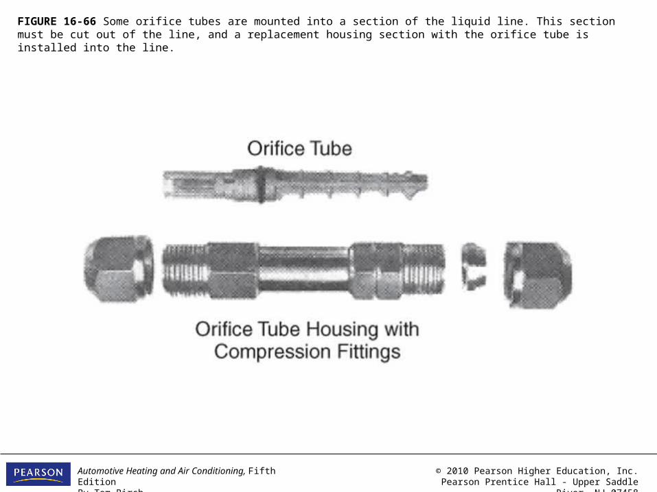
FIGURE 16-66 Some orifice tubes are mounted into a section of the liquid line. This section must be cut out of the line, and a replacement housing section with the orifice tube is installed into the line.
Automotive Heating and Air Conditioning, Fifth EditionBy Tom Birch
© 2010 Pearson Higher Education, Inc.Pearson Prentice Hall - Upper Saddle River, NJ 07458
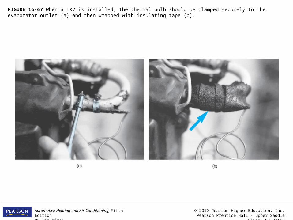
FIGURE 16-67 When a TXV is installed, the thermal bulb should be clamped securely to the evaporator outlet (a) and then wrapped with insulating tape (b).
Related Documents