Welcome message from author
This document is posted to help you gain knowledge. Please leave a comment to let me know what you think about it! Share it to your friends and learn new things together.
Transcript

Automotive EngineeringLightweight, Functional, and Novel Materials
IP155_C000.fm Page i Wednesday, January 9, 2008 11:19 AM
Series in Materials Science and EngineeringSeries Editors: Alwyn Eades, Lehigh University, Bethlehem, Pa., USA Evan Ma, Johns Hopkins University, Baltimore, Md, USA
Other books in the series:
Strained-Si Heterostructure Field Effect Devices C K Maiti, S Chattopadhyay, L K Bera
Spintronic Materials and Technology Y B Xu, S M Thompson (Eds)
Fundamentals of Fibre Reinforced Composite Materials A R Bunsell, J Renard
Novel Nanocrystalline Alloys and Magnetic NanomaterialsB Cantor (Ed)
3-D Nanoelectronic Computer Architecture and ImplementationD Crawley, K Nikolic, M Forshaw (Eds)
Computer Modelling of Heat and Fluid Flow in Materials Processing C P Hong
High-K Gate Dielectrics M Houssa (Ed)
Metal and Ceramic Matrix Composites B Cantor, F P E Dunne, I C Stone (Eds)
High Pressure Surface Science and Engineering Y Gogotsi, V Domnich (Eds)
Physical Methods for Materials Characterisation, Second Edition P E J Flewitt, R K Wild
Topics in the Theory of Solid Materials J M Vail
Solidification and Casting B Cantor, K O’Reilly (Eds)
Fundamentals of Ceramics M W Barsoum
Aerospace Materials B Cantor, H Assender, P Grant (Eds)
IP155_C000.fm Page ii Wednesday, January 9, 2008 11:19 AM
iii
Series in Materials Science and Engineering
Edited by
Brian CantorUniversity of York, UK
Patrick GrantOxford University, UK
Colin JohnstonOxford University, UK
Automotive EngineeringLightweight, Functional, and Novel Materials
New York London
Taylor & Francis is an imprint of theTaylor & Francis Group, an informa business
IP155_C000.fm Page iii Wednesday, January 9, 2008 11:19 AM
CRC PressTaylor & Francis Group6000 Broken Sound Parkway NW, Suite 300Boca Raton, FL 33487-2742
© 2008 by Taylor & Francis Group, LLC CRC Press is an imprint of Taylor & Francis Group, an Informa business
No claim to original U.S. Government worksPrinted in the United States of America on acid-free paper10 9 8 7 6 5 4 3 2 1
International Standard Book Number-13: 978-0-7503-1001-7 (Hardcover)
This book contains information obtained from authentic and highly regarded sources. Reprinted material is quoted with permission, and sources are indicated. A wide variety of references are listed. Reasonable efforts have been made to publish reliable data and information, but the author and the publisher cannot assume responsibility for the validity of all materials or for the conse-quences of their use.
No part of this book may be reprinted, reproduced, transmitted, or utilized in any form by any electronic, mechanical, or other means, now known or hereafter invented, including photocopying, microfilming, and recording, or in any information storage or retrieval system, without written permission from the publishers.
For permission to photocopy or use material electronically from this work, please access www.copyright.com (http://www.copyright.com/) or contact the Copyright Clearance Center, Inc. (CCC) 222 Rosewood Drive, Danvers, MA 01923, 978-750-8400. CCC is a not-for-profit organization that provides licenses and registration for a variety of users. For organizations that have been granted a photocopy license by the CCC, a separate system of payment has been arranged.
Trademark Notice: Product or corporate names may be trademarks or registered trademarks, and are used only for identification and explanation without intent to infringe.
Library of Congress Cataloging-in-Publication Data
Cantor, Brian.Automotive engineering : lightweight, functional, and novel materials / Brian
Cantor, Patrick Grant, Colin Johnston.p. cm.
Includes bibliographical references and index.ISBN 978-0-7503-1001-7 (alk. paper)1. Motor vehicles--Materials. I. Cantor, Brian. II. Grant, Patrick. III. Johnston,
Colin. IV. Title.
TL154.C36 2007629.2’32--dc22 2007015715
Visit the Taylor & Francis Web site athttp://www.taylorandfrancis.com
and the CRC Press Web site athttp://www.crcpress.com
IP155_C000.fm Page iv Wednesday, January 9, 2008 11:19 AM

v
Contents
Preface.................................................................................................... viiAcknowledgments ..................................................................................ixEditors......................................................................................................xiContributors ......................................................................................... xiii
Section 1 Industrial Perspective
1
Future Vehicles and Materials Technologies
............................... 3
Kimihiro Shibata
2
Automobile Aluminum Sheet
..................................................... 19
Takashi Inaba
3
Plastic Technology for Automotive Modules
............................ 29
Kazuhisa Toh
Section 2 Functional Materials
4
Automotive Catalysts
................................................................... 39
Michael Bowker
5
Magnetorheological Fluids
.......................................................... 49
Kevin O’Grady, V. Patel, and S. W. Charles
6
Impact Loading
............................................................................. 63
Nik Petrinic
7
High-Temperature Electronic Materials
.................................... 73
Colin Johnston
8
Smart Materials
............................................................................ 87
Clifford M. Friend
IP155_C000.fm Page v Wednesday, January 9, 2008 11:19 AM

vi
Contents
Section 3 Light Metals
9
Formability of Aluminum Alloys
............................................... 97
Hirofumi Inoue
10
Ductile Magnesium
................................................................... 109
Toshiji Mukai and Kenji Higashi
11
Enhancement of Crashworthiness in Cellular Structures
................................................................. 117
T. Miyoshi, M. Itoh, T. Mukai, S. Nakano, and K. Higashi
12
Compressive Properties of Cellular Metals
............................. 125
Mamoru Mabuchi
13
Heavily Deformable Al Alloy
........................................................ 133
Osamu Umezawa
14
Stainless Steel Sandwich Sheets with Fibrous Metal Cores
.......................................................... 149
A. E. Markaki and Bill Clyne
Section 4 Processing and Manufacturing
15
Welding and Joining
................................................................... 179
J. G. Wylde and J. M. Kell
16
Titanium Aluminide-Based Intermetallic Alloys
.................. 197
Takayuki Takasugi
17
Casting Processes and Simulation Tools
................................ 209
Mark Jolly
18
Damage Tolerance in Composite Structures
............................ 241
Ivana K. Partridge
19
High-Performance Autosport Surface Treatments and Composites
..................................................... 253
Roger Davidson, Ed Allnutt, and Will Battrick
Index
................................................................................................... 267
IP155_C000.fm Page vi Wednesday, January 9, 2008 11:19 AM
vii
Preface
This book is a text on automotive materials, arising from presentations givenat the fifth Oxford–York–Kobe Materials Seminar, held at the Kobe Instituteon 10–13 September 2002.
The Kobe Institute is an independent non-profit-making organization.It was established by donations from Kobe City, Hyogo Prefecture, andmore than 100 companies all over Japan. It is based in Kobe City, Japan,and is operated in collaboration with St. Catherine’s College, OxfordUniversity, United Kingdom. The chairman of the Kobe Institute Com-mittee in the United Kingdom is Roger Ainsworth, master of St. Cathe-rine’s College; the director of the Kobe Institute Board is Dr. YasutomiNishizuka; the academic director is Dr. Helen Mardon, Oxford University;and the bursar is Dr. Kaizaburo Saito. The Kobe Institute was establishedwith the objectives of promoting the pursuit of education and researchthat furthers mutual understanding between Japan and other nations,and to contribute to collaborations and exchanges between academicsand industrial partners.
The Oxford–York–Kobe seminars are research workshops that aim to pro-mote international academic exchanges between the United Kingdom/Europe and Japan. A key feature of the seminars is to provide a world-classforum focused on strengthening connections between academics and indus-try in both Japan and the United Kingdom/Europe, and fostering collabo-rative research on timely problems of mutual interest.
The fifth Oxford–York–Kobe Materials Seminar was on automotive mate-rials, concentrating on developments in science and technology over thenext ten years. The cochairs of the seminar were Dr. Hisashi Hayashi ofRiken, Dr. Takashi Inaba of Kobe Steel, Dr. Kimihiro Shibata of Nissan,Professor Takayuki Takasugi of Osaka Prefecture University, Dr. HiroshiYamagata of Yamaha, Professor Brian Cantor of York University, Dr. PatrickGrant and Dr. Colin Johnston of Oxford University, and Dr. Kaizaburo Saitoof the Kobe Institute. The seminar coordinator was Pippa Gordon ofOxford University. The seminar was sponsored by the Kobe Institute,St. Catherine’s College, the Oxford Centre for Advanced Materials andComposites, the UK Department of Trade and Industry, and FaradayAdvance. Following the seminar, all of the speakers prepared extendedmanuscripts in order to compile a text suitable for graduates and forresearchers entering the field. The contributions are compiled into foursections: industrial perspective, functional materials, light metals, andprocessing and manufacturing.
IP155_C000.fm Page vii Wednesday, January 9, 2008 11:19 AM

viii
Preface
The first four and seventh Oxford–York–Kobe Materials Seminars focusedon aerospace materials in September 1998, solidification and casting inSeptember 1999, metal and ceramic composites in September 2000, nano-materials in September 2001, and spintronic materials in September 2004.The corresponding texts have already been published in the IOPP Seriesin Materials Science and Engineering and are being reprinted by Taylor &Francis. The sixth Oxford–York–Kobe Materials Seminar was on magneticmaterials in September 2003 and the eight Oxford–York–Kobe MaterialsSeminar will be on liquid crystals in April 2008.
IP155_C000.fm Page viii Wednesday, January 9, 2008 11:19 AM
ix
Acknowledgments
The editors would like to thank the Oxford
–
Kobe Institute Committee,St. Catherine’s College, Oxford University, and York University for agreeingto support the Oxford–York–Kobe Materials Seminar on Automotive Materials;Sir Peter Williams, Dr. Hisashi Hayashi, Dr. Takashi Inaba, Dr. Kimihiro Shibata,Professor Takayuki Takasugi, Dr. Hiroshi Yamagata, Dr. Helen Mardon, andDr. Kaizaburo Saito for help in organizing the seminar; and Pippa Gordonand Sarah French for help with preparing the manuscripts.
Individual authors would like to make additional acknowledgments asfollows:
Chapter 3:
We are grateful for the support of the UK funding agencies,the University of Reading, and Toyota for financial support for thiswork.
Chapter 4:
We are grateful for the support of the UK funding agencies,the University of Reading, and Toyota for financial support for thiswork.
Chapter 7:
The author wishes to acknowledge support from HITENand the CEC Thematic Network Programme, and contributionsfrom Riccardo Groppo, Fiat Research, Italy; Wolfgang Wondrak,Daimler Chrysler, Germany; and Wayne Johnson of Auburn Uni-versity, United States.
Chapter 14:
Support for this work has been provided by the Cambridge
–
MIT Institute (CMI). Andrew Cockburn of Cambridge Universitymade some of the stiffness measurements and produced the 3-Darray sheet. Sheets with flocked and mesh cores were provided byJerry Karlsson of HSSA Ltd. Thanks are also due to Steve Westgateof TWI for extensive help with welding activities and to PeterRooney and Lee Marston of FibreTech for ongoing collaborationrelated to supply of fibers and development of the processing tech-nology.
Chapter 16:
The author expresses sincere thanks to Dr. T. Tetsui atMitsubishi Heavy Industries for the supply of some of the TiAl-based intermetallic materials.
IP155_C000.fm Page ix Wednesday, January 9, 2008 11:19 AM

IP155_C000.fm Page x Wednesday, January 9, 2008 11:19 AM
xi
Editors
Brian Cantor
was educated at Manchester Grammar School and Christ’sCollege, Cambridge. He has worked at Sussex, Oxford, and York Universi-ties, and with leading companies, such as Alcan, Elsevier, General Electric,and Rolls-Royce. He is on the boards of White Rose, Worldwide UniversitiesNetwork, Yorkshire Science, and the National Science Learning Centre; andwas on the boards of Amaetham, York Science Park, Isis Innovation, and theKobe Institute. He has advised agencies such as EPSRC, NASA, the EU, andthe Dutch, Spanish, and German governments. At Oxford he was CooksonProfessor of Materials, the first head of the Division of Mathematical andPhysical Sciences, and a member of the General Board and Council. He wasappointed in 2002 as vice-chancellor of the University of York.
His research investigates the manufacture of materials and has contributedto improvements in products such as electrical transformers, pistons, carbrakes, aeroengines, and lithographic sheeting. He has supervised over 130research students and post doctoral fellows, published over 300 papers,books, and patents, and given over 100 invited talks in more than 15 countries.
He was awarded the Rosenhain and Platinum Medals of the Institute ofMaterials, the first for “outstanding academic/industrial collaboration” andthe second for “lifetime contributions to materials science.” He is an honor-ary professor at Northeastern University Shenyang, Zhejiang University, andthe Chinese Institute of Materials, and is a member of the Academia Europea,and the World Technology Forum and is on the ISI list of Most Cited Scien-tists. He is a fellow of the Institute of Materials, the Institute of Physics, andthe Royal Academy of Engineering, elected to the Royal Academy as “aworld authority on materials manufacturing.”
Patrick Grant
received a B.Eng. in metallurgy and materials science fromNottingham University in 1987, and a D.Phil. in materials from OxfordUniversity in 1991. He was a Royal Society University research fellow andReader in the Department of Materials, Oxford University, and became Cook-son Professor of Materials at Oxford University in 2004. His published workof over 100 papers concerns advanced materials and processes for industrialstructural and functional applications, especially in the aerospace and auto-motive sectors. He has been granted three patents licensed to industry.
He was director of the Oxford Centre for Advanced Materials and Com-posites (1999
–
2004) that coordinates industrially related materials at OxfordUniversity and is currently director of Faraday Advance, a component ofthe Materials Knowledge Transfer Network, a government and industryfunded national partnership that links the science base with industry in the
IP155_C000.fm Page xi Wednesday, January 9, 2008 11:19 AM
xii
Editors
field of advanced materials. Faraday Advance focuses on new materials—lightweight and low environmental impact materials for transport applica-tions. He is a member of the 2008 Research Assessment Exercise Panel forMaterials and a member of the Defense and Aerospace National AdvisoryCommittee for Materials and Structures.
Colin Johnston
splits his time as a technology translator with FaradayAdvance—the Transport Node of the Materials Knowledge TransferNetwork—and as coordinator of the Institute of Industrial Materials andManufacturing section of the Department of Materials, Oxford University,where he has held the position of senior research fellow since 2001. Hereceived a B.Sc. (Honors) in chemistry from the University of Dundee in1984, followed by a Ph.D. in surface science and catalysis in 1987, also fromthe University of Dundee. In 1987 he joined AEA Technology at the HarwellLaboratory where he was a member of the Materials Development Divisionspecializing in materials characterization. He later developed electronicmaterials for harsh environments, working on wide band gap semiconduc-tors and microsystems. Johnston was operations manager of the ElectronicMaterials and Thermal Management business of AEA Technology from 1998to 2000, when he assumed a post within the central corporate structure,managing innovation and new technology acquisitions for the company.
He is director of HITEN—the EU-funded network for high temperatureelectronics, where he established a pan-European strategy. He is also cochairof the U.S. High Temperature Electronics Biennial Conference Series and haspublished over 80 papers in scientific journals and edited several books onhigh-temperature electronics.
IP155_C000.fm Page xii Wednesday, January 9, 2008 11:19 AM

xiii
Contributors
Ed Allnutt
Crompton Technology Group Ltd.Banbury, Oxon United Kingdom
Will Battrick
Crompton Technology Group Ltd.Banbury, Oxon United Kingdom
Michael Bowker
School of ChemistryCardiff UniversityCardiff, United Kingdom
S. W. Charles
Department of PhysicsUniversity of York Heslington, York, United Kingdom
T. W. Clyne
Engineering DepartmentUniversity of Cambridge Cambridge, United Kingdom
Roger Davidson
Crompton Technology Group Ltd.Banbury, Oxon United Kingdom
Clifford M. Friend
Cranfield UniversityCranfield, BedfordshireUnited Kingdom
Kenji Higashi
Osaka Municipal Technical Research Institute
Osaka Prefecture UniversityNakaku, SakaiOsaka, Japan
Takashi Inaba
Kobe SteelChuo-ku, KobeHyogo, Japan
Hirofumi Inoue
Department of Materials ScienceOsaka Prefecture UniversityNakaku, SakaiOsaka, Japan
M. Itoh
Shinko Wire Company Ltd.Izumisano, Japan
Colin Johnston
Department of MaterialsOxford UniversityOxford, United Kingdom
Mark Jolly
Process Modelling GroupUniversity of BirminghamBirmingham, United Kingdom
J. M. Kell
TWI Ltd. Great Abington, CambridgeUnited Kingdom
Mamoru Mabuchi
National Industrial Research Institute of Nagoya
Nagoya, Japan
A. E. Markaki
Engineering DepartmentUniversity of Cambridge Cambridge, United Kingdom
IP155_C000.fm Page xiii Wednesday, January 9, 2008 11:19 AM

xiv
Contributors
T. Miyoshi
Shinko Wire Company Ltd.Izumisano, Japan
Toshiji Mukai
Osaka Municipal Technical Research Institute
Osaka Prefecture UniversityNakaku, SakaiOsaka, Japan
T. Mukai
Shinko Wire Company Ltd.Izumisano, Japan
S. Nakano
Shinko Wire Company Ltd.Izumisano, Japan
Kevin O’Grady
Department of PhysicsUniversity of York Heslington, York United Kingdom
Ivana K. Partridge
Cranfield UniversityCranfield, BedfordshireUnited Kingdom
V. Patel
Department of PhysicsUniversity of YorkHeslington, York United Kingdom
Nik Petrinic
Department of Engineering ScienceOxford UniversityOxford, United Kingdom
Kimihiro Shibata
Department of Materials Science and Engineering
Miyagi National College of Technology
Natori, MiyagiJapan
Takayuki Takasugi
Department of Metallurgy and Materials Science
Osaka Prefectural UniversitySakai, OsakaJapan
Kazuhisa Toh
Mazda Motor CorporationKanagawa-ku, YokohamaKanagawa, Japan
Osamu Umezawa
Yokohoma National UniversityDivision of Mechanical Engineering
and Materials ScienceHodogaya, Yokohama Japan
J. G. Wylde
TWI Ltd. Great Abington, CambridgeUnited Kingdom
IP155_C000.fm Page xiv Wednesday, January 9, 2008 11:19 AM

Section 1
Industrial Perspective
Cars and automobiles are developing rapidly, with increasing global com-petition between industrial manufacturing companies, and with increasingsocial requirements for reduced noise and pollution, increased safety andenergy efficiency, higher performance, and, at the same time, reduced cost.New materials and processing techniques are needed to underpin thesedevelopments. The industrial scene, the key design drivers, and the emerg-ing new materials and processing technologies are covered in detail in thissection.
Chapter 1 discusses the development of future vehicles and the associatednew materials for a wide range of automotive components, concentratingon the importance of improved safety, reduced environmental damage, therole of information processing, and the overarching need for cost-effective-ness in a competitive market. Chapters 2 and 3 concentrate on more specificissues. Chapter 2 describes the development of suitable aluminum alloysand associated processing techniques to manufacture lighter body panels,with improvements in energy efficiency, fuel savings, and performance.Chapter 3 describes the development of a variety of different polymer com-posites and their associated moulding techniques to make stronger and moreeffective module carriers, which are used to allow rapid and cost-efficientmanufacture of complex multiple parts.
IP155_S001.fm Page 1 Monday, December 10, 2007 4:13 PM

IP155_S001.fm Page 2 Monday, December 10, 2007 4:13 PM

3
1
Future Vehicles and Materials Technologies
Kimihiro Shibata
CONTENTS
Introduction .............................................................................................................3Environmental Issues .............................................................................................4Safety.........................................................................................................................6Intelligent Transportation Systems (ITS) ............................................................7Market Trends .........................................................................................................8Automotive Materials ........................................................................................... 9
Car Body Materials........................................................................................9Materials for Engine Components............................................................10Materials for Chassis and Powertrain Components.............................. 11Future Direction of Automotive Materials.............................................. 11
Environmental Viewpoint ...................................................................................12Safety Viewpoint ...................................................................................................14Summary ................................................................................................................16References...............................................................................................................17
Introduction
In the twenty-first century, cars should be designed and engineered to be inharmony with people and nature. Environmental and safety issues today callfor technological improvements. Reduction of CO
2
emissions and improvementof fuel economy can be achieved together with crashworthiness through con-tributions made by material technologies. Besides improving mechanical prop-erties and cost competitiveness, peripheral technical issues, such as formingand joining technologies, and environmental performance, should be addressedprior to the deployment of a new material. Cooperation among material sup-pliers, parts suppliers and carmakers, or among carmakers themselves, in asimultaneous or concurrent manner, is becoming more important than ever.
IP155_C001.fm Page 3 Monday, December 31, 2007 4:48 PM
4
Automotive Engineering: Lightweight, Functional, and Novel Materials
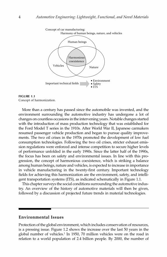
More than a century has passed since the automobile was invented, and theenvironment surrounding the automotive industry has undergone a lot ofchanges on countless occasions in the intervening years. Notable changes startedwith the introduction of mass production technology that was established forthe Ford Model T series in the 1910s. After World War II, Japanese carmakersresumed passenger vehicle production and began to pursue quality improve-ments. The two oil crises in the 1970s promoted the development of low fuelconsumption technologies. Following the two oil crises, stricter exhaust emis-sion regulations were enforced and intense competition to secure higher levelsof performance unfolded in the early 1990s. Since the latter half of the 1990s,the focus has been on safety and environmental issues. In line with this pro-gression, the concept of harmonious coexistence, which is striking a balanceamong human beings, nature and vehicles, is expected to increase in importancein vehicle manufacturing in the twenty-first century. Important technologyfields for achieving this harmonization are the environment, safety, and intelli-gent transportation systems (ITS), as indicated schematically in Figure 1.1.
This chapter surveys the social conditions surrounding the automotive indus-try. An overview of the history of automotive materials will then be given,followed by a discussion of projected future trends in material technologies.
Environmental Issues
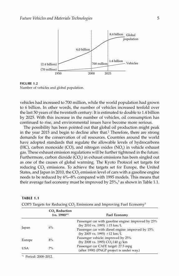
Protection of the global environment, which includes conservation of resources,is a pressing issue. Figure 1.2 shows the increase over the last 50 years in theglobal number of vehicles.
1
In 1950, 70 million vehicles were on the road inrelation to a world population of 2.4 billion people. By 2000, the number of
FIGURE 1.1
Concept of harmonization.
Important technical fields• Environment• Safety• ITS
Human beings
NatureVehicles
Harmoniouscoexistence
Concept of car manufacturing: Harmony of human beings, nature, and vehicles
IP155_C001.fm Page 4 Monday, December 31, 2007 4:48 PM
Future Vehicles and Materials Technologies
5
vehicles had increased to 700 million, while the world population had grownto 6 billion. In other words, the number of vehicles increased tenfold overthe last 50 years of the twentieth century: It is estimated to double to 1.4 billionby 2025. With this increase in the number of vehicles, oil consumption hascontinued to rise, and environmental issues have become more serious.
The possibility has been pointed out that global oil production might peakin the year 2015 and begin to decline after that.
2
Therefore, there are strongdemands for the conservation of oil resources. Countries around the worldhave adopted standards that regulate the allowable levels of hydrocarbons(HC), carbon monoxide (CO), and nitrogen oxides (NO
x
) in vehicle exhaustgas. These exhaust emission regulations will be further tightened in the future.Furthermore, carbon dioxide (CO
2
) in exhaust emissions has been singled outas one of the causes of global warming. The Kyoto Protocol set targets forreducing CO
2
emissions. To achieve the targets set for Europe, the UnitedStates, and Japan in 2010, the CO
2
emission level of cars with a gasoline engineneeds to be reduced by 6%
–
8% compared with 1995 models. This means thattheir average fuel economy must be improved by 25%,
3
as shown in Table 1.1.
FIGURE 1.2
Number of vehicles and global population.
TABLE 1.1
COP3 Targets for Reducing CO
2
Emissions and Improving Fuel Economy
3
CO
2
Reduction(vs. 1990)*
1
Fuel Economy
Japan 6%
Passenger car with gasoline engine: improved by 23%(by 2010 vs. 1995)
�
15 km/LPassenger car with diesel engine: improved by 15%(by 2005 vs. 1995)
�
12 km/L
Europe 8%Passenger vehicle: improved by 25%(by 2008 vs. 1995) CO
2
:140 g/km
USA 7%Passenger car CAFE target: 27.5 mpg(after 1990) (PNGP project is under way.)
*1
Period: 2008–2012.
1950 2000 2025
(2.4 billion)
6.0 billion
8.4 billion
700 million1.4 billion
Globalpopulation
Vehicles
(70 million)
IP155_C001.fm Page 5 Monday, December 31, 2007 4:48 PM

6
Automotive Engineering: Lightweight, Functional, and Novel Materials
These targets were ratified in 2002, with the exception of the United States,and vigorous steps are being taken to improve vehicle fuel economy.
Safety
In order to improve the safety of vehicles, information safety for preventingaccidents in addition to crash safety is becoming more important, as shownin Figure 1.3. In the course of developing technologies for improving crashsafety, traffic accidents are reproduced and analyzed. The results of theseanalyses have been applied to develop new crash safety technologies, suchas an automatic braking system for reducing the collision speed, and anemergency stopping system. In the area of information safety, advancedsafety vehicles and advanced highway systems are being developed usingsophisticated technologies like intelligent vision-sensing and car-to-car com-munication systems.
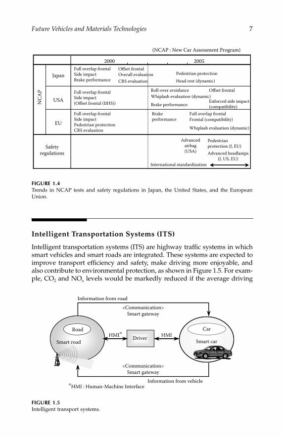
In recent years, the results of car crash tests conducted under a new carassessment program (NCAP) in various countries, as well as the accidentrates of individual car models, have been disclosed. Such data are usuallyconsidered in the determination of car insurance premiums. Due tostricter safety regulations and the disclosure of information regardingsafety, consumers are more concerned about safety today than ever before.Based on analyses of traffic accidents, the new car assessment programwill continue to adopt more precise and sophisticated collision tests.Various new car assessment tests and regulations concerning crash safetyare being prepared for implementation in the coming years, as shown inFigure 1.4.
FIGURE 1.3
Vehicle crash safety and information safety.
AccidentCrashsafety
Use of high technology• Intelligent vision-sensing system• Car-to-car communication• Use of infrastructure
Accident analysis &accident reproduction
• Advanced safety vehicles• Advanced highway systems
• Automatic braking system for reducing collision speed• Emergency stopping system
Informationsafety
Information disclosure(NCAP, accident rates,
insurance premium rates)
Regulations
New crash safety technologies
IP155_C001.fm Page 6 Monday, December 31, 2007 4:48 PM
Future Vehicles and Materials Technologies
7
Intelligent Transportation Systems (ITS)
Intelligent transportation systems (ITS) are highway traffic systems in whichsmart vehicles and smart roads are integrated. These systems are expected toimprove transport efficiency and safety, make driving more enjoyable, andalso contribute to environmental protection, as shown in Figure 1.5. For exam-ple, CO
2
and NO
x
levels would be markedly reduced if the average driving
FIGURE 1.4
Trends in NCAP tests and safety regulations in Japan, the United States, and the EuropeanUnion.
FIGURE 1.5
Intelligent transport systems.
2000 2005 Full overlap frontal Side impact Brake performance
Offset frontalJapan
USA
EU
Pedestrian protection
Full overlap frontal Side impact (Offset frontal (IIHS)) Brake performance
Roll-over avoidance
Whiplash evaluation (dynamic)
Offset frontal
Enforced side impact(compatibility)
Safetyregulations
Full overlap frontal Side impact Pedestrian protection CRS evaluation
Brakeperformance
Full overlap frontalFrontal (compatibility)
Advancedairbag(USA)
Pedestrianprotection (J, EU)Advanced headlamps
(J, US, EU)International standardization
Whiplash evaluation (dynamic)
Head rest (dynamic) CRS evaluation
(NCAP : New Car Assessment Program)
NC
AP
Overall evaluation
Smart road Smart carDriverRoad Car
HMI∗ HMI
<Communication>Smart gateway
Information from vehicle
<Communication>Smart gateway
∗HMI : Human-Machine Interface
Information from road
IP155_C001.fm Page 7 Monday, December 31, 2007 4:48 PM

8
Automotive Engineering: Lightweight, Functional, and Novel Materials
speed during traffic congestion could be increased from 10 to 20 km/h throughthe use of an intelligent transportation system,
4
as shown in Figure 1.6. More-over, the number of traffic accidents might also be reduced, for example, byapplying an adaptive cruise control system together with intelligent transpor-tation system capabilities.
Market Trends
Customer needs are becoming greatly diversified, and the speed at whichthey are changing is accelerating. During Japan’s bubble economy in the late1980s, customers preferred luxurious products of a uniform style, but vehi-cles having good cost performance and individuality have been well receivedin recent years. Car manufacturers also have to respond to social issues. Akey question is how fast a car manufacturer can provide vehicles that firstlymeet customers’ demands and social requirements, and secondly are avail-able at low prices. In order to satisfy market demands, vehicle manufacturingis changing as follows:
Common use of low-cost materials procured globallyUse of common platforms for increasing investment efficiency and
reducing development costsOutsourcing for increasing development speed
These changes in vehicle manufacturing are undermining the traditional“keiretsu” system of company groupings in Japan. Today, automobile partsare assembled into modules by suppliers and provided to car manufacturers,
FIGURE 1.6
Emission levels as a function of average vehicle speed.
4
(Example for a 2-ton truck)
CO2 e
miss
ion
(g/k
m)
100
200
300
400
500
600
0 20 40 60 80 100
23% Reduction
NO
X em
issio
n in
dex
0
100
200
300
400
500
38% Reduction
20 40 60 800Average vehicle speed (km/h)
100
Avg. speed10 → 20 km/h Avg. speed
10 → 20 km/h
Average vehicle speed (km/h)
(Example for a 2000 ccpassenger car)
0
IP155_C001.fm Page 8 Monday, December 31, 2007 4:48 PM

Future Vehicles and Materials Technologies
9
and it is not unusual nowadays for rival carmakers to purchase parts fromthe same parts supplier. The traditional vertical integration of companies ischanging to more horizontal integration, as indicated in Figure 1.7. Thishorizontal integration is basically composed of “give & take” relationships.The idea that everything should be done in-house or by “keiretsu” compa-nies has vanished. In this new structure, global networks for information,cooperation, and human resources are becoming very important elementsof corporate competitiveness.
Automotive Materials
Figure 1.8 shows a history of automotive, mainly metal, materials. Over theyears, new materials have been developed along with changes in socialconditions and market requirements.
Car Body Materials
New materials for the car body have been developed to improve corrosionresistance and to reduce vehicle weight. In the 1950s and 1960s, mass pro-duction technologies were developed because of higher vehicle demand.High performance and reliability were also the market trends at that time.Deep drawing steel sheets with good formability were developed in the 1950s,followed by the development of anti-corrosive steel sheets in the 1960s. Inthe 1970s and 1980s, low fuel consumption was a keen issue because of the
FIGURE 1.7
Alternative types of company grouping.
Vertical Integration
Carmaker
Carmaker
Supplier
Supplier
Supplier
Supplier
Supplier
Supplier
Horizontal Integration
Carmaker
Secondary supplier
SupplierSecondary supplierPrimary supplier
Carmaker
Primary supplierSecondary supplier
Carmaker
Primary supplier
IP155_C001.fm Page 9 Monday, December 31, 2007 4:48 PM

10
Automotive Engineering: Lightweight, Functional, and Novel Materials
two oil crises. High-strength steel sheets were developed in response to thisissue and have contributed to lightening vehicles by reducing sheet thick-ness. In the 1990s, safety and environmental issues became primary concernsin the automotive industry, and further work was done on developing tech-nologies for weight reductions. Aluminum alloy sheets were developed inthis connection and applied to various body panels such as the engine hood,and have contributed to achieving lighter vehicles.
Materials for Engine Components
New materials for engines have been developed to improve engine durabil-ity and performance as well as to reduce the weight of components. In the1950s, ductile cast iron suitable for volume production was developed andapplied to crankshafts. In the 1980s, micro-alloyed steels were developedand applied to crankshafts and connecting rods. Sinter-forged connectingrods were also developed. For the sake of weight reductions, aluminumalloys were used for cylinder heads, and stainless steels for exhaust mani-folds. In the 1990s, aluminum alloys were applied to cylinder blocks, andmagnesium alloys to cylinder head covers.
FIGURE 1.8
New materials used in vehicles.
Anti-slip lining Composite drive shaft
Body
Engine
Drive-train
Chassis
1940 1960 1970 1980 1990
Localization,reliability
Energysavings
Emissions,safety, noise
High speed,mass production
Safety, environment, diverse needs
Highperformance
Deep drawing steel HSSGalvanized steel Anti-corrosion steel
Al outer panelDuctile iron crankshaft
Al cylinder headAl cylinder block Mg head cover
Laser clad valve seat
Al transmission case Mg transmission casePb added free cutting steel gear
Al wheel
Al forged upper arm Non-asbestos brake pad
Micro-alloyed beam, knuckle, arm Mg steering bracket
Micro-alloyed steel crankshaft
Stainless steel exhaust manifold
2-layer galvanized steel sheet
Plastic fuel tankSuper olefin elastomer bumper
Urethane bumperPP bumper
High lubrication coated steel sheet
Oxidation catalysis
3-way catalystO2 sensor
Reinforced glass Plastic headlampUV blocking glass
FRP-roof panel
S added free cutting steel gear
Non-asbestos A/T lining
Non-asbestos clutch facing
Al steering gear housing
Al differential gear case HSS suspension memberInduction hardened knuckle arm
Al piston FRP head cover
NOX storage reduction catalystMetal honeycomb catalyst
Sintered alloy valve seat
Sinter-forged con’rod Free cutting steel crankshaft
Ceramic turbochargerPlastic air cleaner casePlastic cylinderhead cover
Plastic intake manifold
Laminated glass
High Si DCIexhaust manifold
Dumper steel oil pan
Social conditionsMarket trends
MITI Nationalvehicle project Oil crisisExhaust gas
regulation
Localproductionin USA/EU
Ozone layerprotection law
Recycle law
IP155_C001.fm Page 10 Monday, December 31, 2007 4:48 PM
Future Vehicles and Materials Technologies
11
Materials for Chassis and Powertrain Components
New materials for chassis and powertrain components have been developedmainly to improve durability and reduce weight. High-strength steel sheetswere applied for suspension members and aluminum alloys for wheels.Knuckles, arms, and I-beams made of micro-alloyed steels were developed.Aluminum alloys are now being used for transmission cases. Gears are madeof free-cutting steels. In recent years, magnesium alloys have been appliedto steering system components and transmission cases. Carbon compositeswith fiber-reinforcement have begun to be used for propeller shafts.
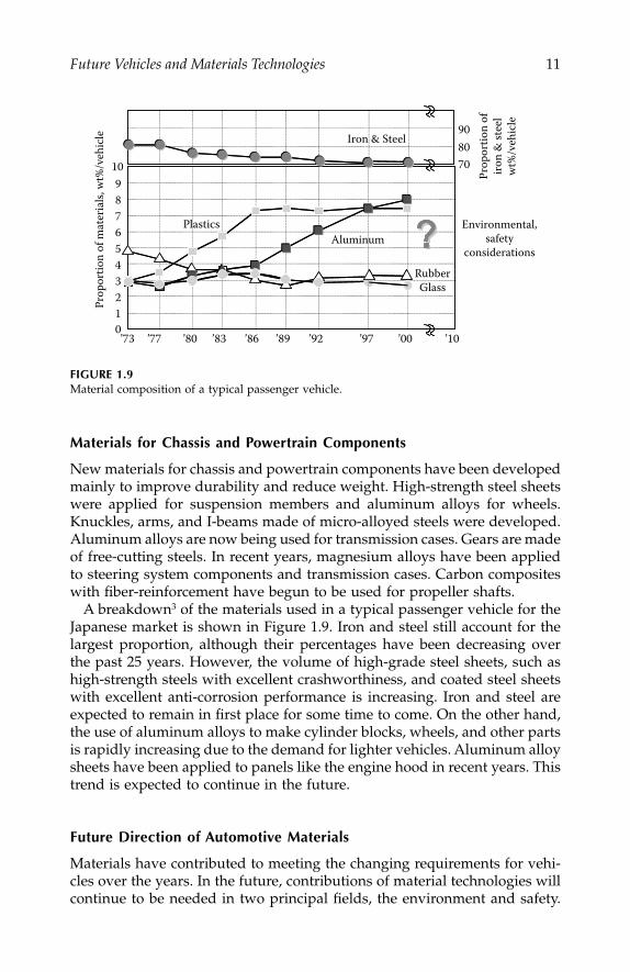
A breakdown
3
of the materials used in a typical passenger vehicle for theJapanese market is shown in Figure 1.9. Iron and steel still account for thelargest proportion, although their percentages have been decreasing overthe past 25 years. However, the volume of high-grade steel sheets, such ashigh-strength steels with excellent crashworthiness, and coated steel sheetswith excellent anti-corrosion performance is increasing. Iron and steel areexpected to remain in first place for some time to come. On the other hand,the use of aluminum alloys to make cylinder blocks, wheels, and other partsis rapidly increasing due to the demand for lighter vehicles. Aluminum alloysheets have been applied to panels like the engine hood in recent years. Thistrend is expected to continue in the future.
Future Direction of Automotive Materials
Materials have contributed to meeting the changing requirements for vehi-cles over the years. In the future, contributions of material technologies willcontinue to be needed in two principal fields, the environment and safety.
FIGURE 1.9
Material composition of a typical passenger vehicle.
10
Prop
ortio
n of
mat
eria
ls, w
t%/v
ehic
le 908070
Prop
ortio
n of
iron
& st
eel
wt%
/veh
icle
9876543210’73 ’77 ’80 ’83 ’86 ’89 ’92 ’97 ’00 ’10
Environmental,safety
considerations
RubberGlass
AluminumPlastics
Iron & Steel
IP155_C001.fm Page 11 Monday, December 31, 2007 4:48 PM
12
Automotive Engineering: Lightweight, Functional, and Novel Materials
The projected future direction of related technologies in each field is dis-cussed in the following sections.
Environmental Viewpoint
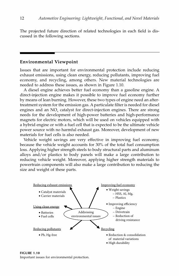
Issues that are important for environmental protection include reducingexhaust emissions, using clean energy, reducing pollutants, improving fueleconomy, and recycling, among others. New material technologies areneeded to address these issues, as shown in Figure 1.10.
A diesel engine achieves better fuel economy than a gasoline engine. Adirect-injection engine makes it possible to improve fuel economy furtherby means of lean burning. However, these two types of engine need an after-treatment system for the emission gas. A particulate filter is needed for dieselengines and an NO
x
catalyst for direct-injection engines. There are strongneeds for the development of high-power batteries and high-performancemagnets for electric motors, which will be used on vehicles equipped witha hybrid engine or with a fuel cell that is expected to be the ultimate vehiclepower source with no harmful exhaust gas. Moreover, development of newmaterials for fuel cells is also needed.
Vehicle weight savings are very effective in improving fuel economy,because the vehicle weight accounts for 30% of the total fuel consumptionloss. Applying higher strength steels to body structural parts and aluminumalloys and/or plastics to body panels will make a large contribution toreducing vehicle weight. Moreover, applying higher strength materials topowertrain components will also make a large contribution to reducing thesize and weight of these parts.
FIGURE 1.10
Important issues for environmental protection.
Recycling
Improving fuel economyReducing exhaust emissions
Using clean energy
• Catalyst materials• Carrier materials
• Batteries• Fuel cells
Reducing pollutants
• Pb, Hg-free • Reduction & consolidation of material variations• High durability
• Improving efficiency – Engine – Drivetrain – Reduction of driving resistance
Addressingenvironmental issues
• Weight savings – HSS, Al, Mg, – Plastics
IP155_C001.fm Page 12 Monday, December 31, 2007 4:48 PM
Future Vehicles and Materials Technologies
13
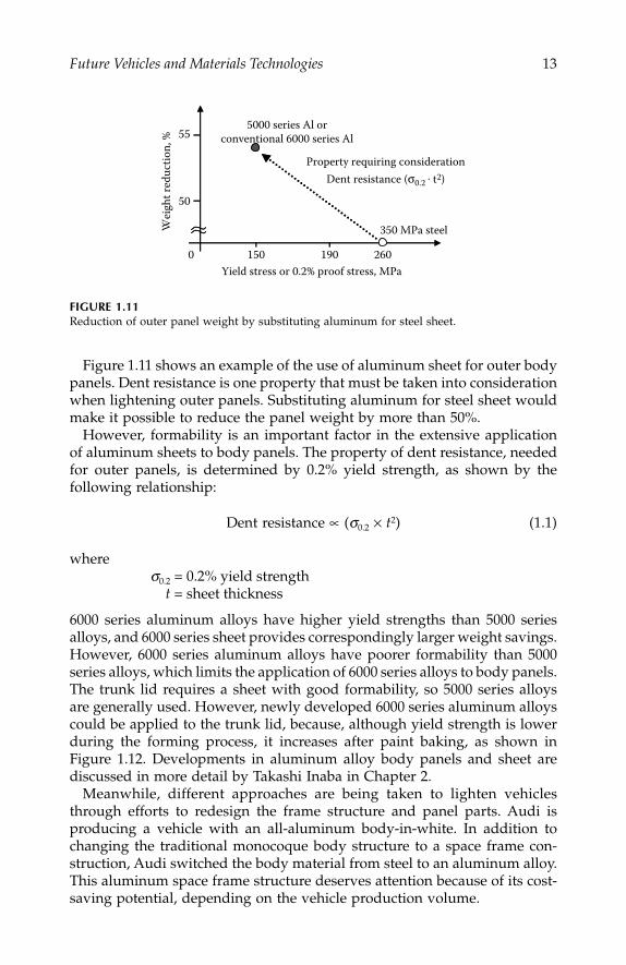
Figure 1.11 shows an example of the use of aluminum sheet for outer bodypanels. Dent resistance is one property that must be taken into considerationwhen lightening outer panels. Substituting aluminum for steel sheet wouldmake it possible to reduce the panel weight by more than 50%.
However, formability is an important factor in the extensive applicationof aluminum sheets to body panels. The property of dent resistance, neededfor outer panels, is determined by 0.2% yield strength, as shown by thefollowing relationship:
Dent resistance
∝
(
σ
0.2
×
t
2
) (1.1)
where
σ
0.2
= 0.2% yield strength
t
= sheet thickness
6000 series aluminum alloys have higher yield strengths than 5000 seriesalloys, and 6000 series sheet provides correspondingly larger weight savings.However, 6000 series aluminum alloys have poorer formability than 5000series alloys, which limits the application of 6000 series alloys to body panels.The trunk lid requires a sheet with good formability, so 5000 series alloysare generally used. However, newly developed 6000 series aluminum alloyscould be applied to the trunk lid, because, although yield strength is lowerduring the forming process, it increases after paint baking, as shown inFigure 1.12. Developments in aluminum alloy body panels and sheet arediscussed in more detail by Takashi Inaba in Chapter 2.
Meanwhile, different approaches are being taken to lighten vehiclesthrough efforts to redesign the frame structure and panel parts. Audi isproducing a vehicle with an all-aluminum body-in-white. In addition tochanging the traditional monocoque body structure to a space frame con-struction, Audi switched the body material from steel to an aluminum alloy.This aluminum space frame structure deserves attention because of its cost-saving potential, depending on the vehicle production volume.
FIGURE 1.11
Reduction of outer panel weight by substituting aluminum for steel sheet.
260Yield stress or 0.2% proof stress, MPa
190150
Wei
ght r
educ
tion,
%
350 MPa steel
5000 series Al orconventional 6000 series Al
0
50
55
Property requiring considerationDent resistance (σ0.2 . t2)
IP155_C001.fm Page 13 Monday, December 31, 2007 4:48 PM

14
Automotive Engineering: Lightweight, Functional, and Novel Materials
On the other hand, magnesium alloys are being used only in small quan-tities in the automobile today. However, magnesium alloys could have alarge effect on reducing vehicle weight due to their low density. Therefore,it is hoped that technologies will be developed for applying magnesiumalloys to automotive components.
Friction in an engine accounts for 40% of all the fuel consumption loss.There is a need to develop technologies for reducing the friction coefficientand weight of engine components, in particular the valve train and piston-crank systems, in order to contribute to improving fuel economy. Higherwear-resistant materials and surface treatments are needed for reducingload stress by lightening the weight of components and reducing the contactarea.
Safety Viewpoint
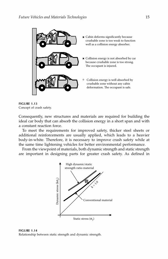
Material technologies are also expected to contribute to improving crash-worthiness. In order to achieve a safe car body in the event of a collision,deformation of the cabin structure should be minimized to protect the occu-pants, and the collision energy should be absorbed in a short deformationlength within the crushable zones, as shown in Figure 1.13.
However, the reaction force generally exceeds an appropriate level whena material with higher strength is applied to an energy-absorbing location.
FIGURE 1.12
Trends in aluminum sheet usage for outer panels.
0.2%
Pro
of st
ress
afte
rba
ke-h
arde
ning
, MPa
Shee
t thi
ckne
ss, m
m
Wei
ght r
educ
tion
rate
, %
Betterformability
required
150
200
HoodFront fenders
Trunk lid
1.0
0.9
0
10
High-formability5000 series
Conventional 6000 series
Conventional5000 series
Future trendNewly developed
6000 series
IP155_C001.fm Page 14 Monday, December 31, 2007 4:48 PM
Future Vehicles and Materials Technologies
15
Consequently, new structures and materials are required for building theideal car body that can absorb the collision energy in a short span and witha constant reaction force.
To meet the requirements for improved safety, thicker steel sheets oradditional reinforcements are usually applied, which leads to a heavierbody-in-white. Therefore, it is necessary to improve crash safety while atthe same time lightening vehicles for better environmental performance.
From the viewpoint of materials, both dynamic strength and static strengthare important in designing parts for greater crash safety. As defined in
FIGURE 1.13
Concept of crash safety.
FIGURE 1.14
Relationship between static strength and dynamic strength.
Cabin deforms significantly becausecrushable zone is too weak to functionwell as a collision energy absorber.
Collision energy is not absorbed by carbecause crushable zone is too strong.The occupant is injured.
Collision energy is well absorbed by crushable zone without any cabindeformation. The occupant is safe.
Static stress (σy)
Dyn
amic
stre
ss (k
σ y)
k = 1.0
Conventional material
High dynamic/static strength ratio material
IP155_C001.fm Page 15 Monday, December 31, 2007 4:48 PM
16
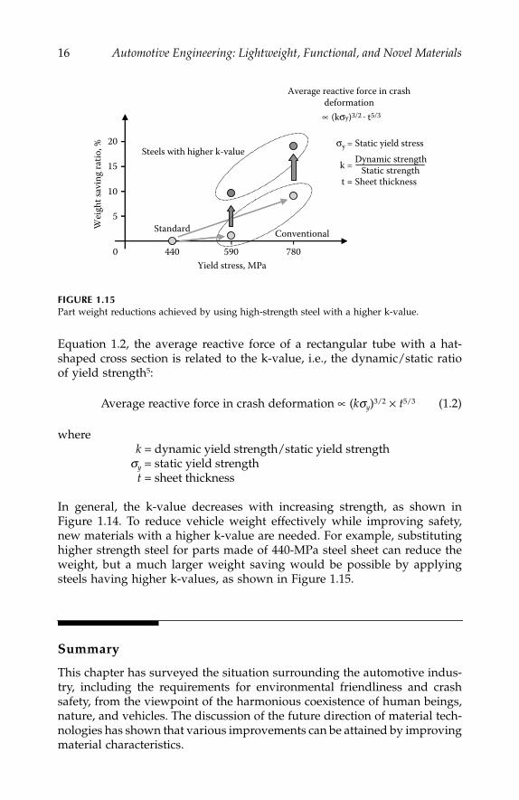
Automotive Engineering: Lightweight, Functional, and Novel Materials
Equation 1.2, the average reactive force of a rectangular tube with a hat-shaped cross section is related to the k-value, i.e., the dynamic/static ratioof yield strength
5
:
Average reactive force in crash deformation
∝
(
k
σ
y
)
3/2
×
t
5/3
(1.2)
where
k
= dynamic yield strength/static yield strength
σ
y
= static yield strength
t
= sheet thickness
In general, the k-value decreases with increasing strength, as shown inFigure 1.14. To reduce vehicle weight effectively while improving safety,new materials with a higher k-value are needed. For example, substitutinghigher strength steel for parts made of 440-MPa steel sheet can reduce theweight, but a much larger weight saving would be possible by applyingsteels having higher k-values, as shown in Figure 1.15.
Summary
This chapter has surveyed the situation surrounding the automotive indus-try, including the requirements for environmental friendliness and crashsafety, from the viewpoint of the harmonious coexistence of human beings,nature, and vehicles. The discussion of the future direction of material tech-nologies has shown that various improvements can be attained by improvingmaterial characteristics.
FIGURE 1.15
Part weight reductions achieved by using high-strength steel with a higher k-value.
Average reactive force in crashdeformation∝ (kσy)3/2 . t5/3
780Yield stress, MPa
590440
Wei
ght s
avin
g ra
tio, %
0
10
15
20
5
Steels with higher k-value
ConventionalStandard
k = Static strengthDynamic strength
σy = Static yield stress
t = Sheet thickness
IP155_C001.fm Page 16 Monday, December 31, 2007 4:48 PM
Future Vehicles and Materials Technologies
17
However, in order to apply a new material to a vehicle, cost competitive-ness and the availability of a global supply both need to be ensured. At thesame time, peripheral technical issues such as forming and joining technolo-gies and environmental performance should also be addressed. Regardingthe cost of materials, one guideline for future material selection is likely tobe a specified level of cost performance from the customer’s viewpoint.Moreover, in order to overcome these technical issues, simultaneous or con-current engineering by materials suppliers, parts suppliers, and car manu-facturers, or among car manufacturers, is becoming more important thanever before.
References
1. Japan Automobile Manufacturers Association, Inc. (JAMA): Japanese Automo-tive Industry, 2001 (in Japanese).
2. IEA/OECD:
World Energy Outlook
, 1998.3. JAMA Web site: http://www.jama.or.jp.4. Source: Japan Automobile Research Institute, Inc.5. Aya, N., and K. Takahashi,
Energy Absorbing Characteristics of Body Structures
(Part 1), JSAE, Vol. 7, 60, 1974 (in Japanese).
IP155_C001.fm Page 17 Monday, December 31, 2007 4:48 PM

IP155_C001.fm Page 18 Monday, December 31, 2007 4:48 PM
19
2
Automobile Aluminum Sheet
Takashi Inaba
CONTENTS
Introduction ...........................................................................................................19Aluminum Body Panel Usage ............................................................................20
Europe and North America .......................................................................20Japan ..............................................................................................................21
Aluminum Alloys for Body Panels....................................................................22Increasing Aluminum Body Panel Usage.........................................................24
Aluminum Alloys ........................................................................................24Forming Technology ...................................................................................25Recycling .......................................................................................................26
Summary ................................................................................................................27References...............................................................................................................27
Introduction
In recent years, environmental improvement and safety have become veryimportant for the automobile industry. Environmental improvement andsafety features lead to increases in car body weight. To reduce weight, there-fore, it is necessary to select optimum materials such as aluminum alloys.
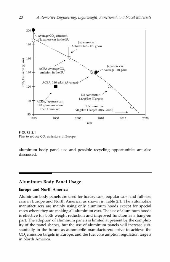
Figure 2.1 shows the plan to reduce CO
2
emissions in Europe.
1
Europeanautomobile manufacturers have to achieve an average CO
2
emission targetof 140 g/km for their fleet of new cars to be sold in 2008.
2,3
Japanese auto-mobile manufacturers have to achieve the same target by 2009. In NorthAmerica and Japan,
1
automobile manufacturers also have to achieve fuelconsumption regulation targets. For these reasons, aluminum alloys areessential to reduce the weight of car bodies.
This chapter provides general information on how aluminum body panelsare used in Europe, North America, and Japan. The promotion of increased
IP155_C002.fm Page 19 Monday, December 31, 2007 4:49 PM
20
Automotive Engineering: Lightweight, Functional, and Novel Materials
aluminum body panel use and possible recycling opportunities are alsodiscussed.
Aluminum Body Panel Usage
Europe and North America
Aluminum body panels are used for luxury cars, popular cars, and full-sizecars in Europe and North America, as shown in Table 2.1. The automobilemanufacturers are mainly using only aluminum hoods except for specialcases where they are making all-aluminum cars. The use of aluminum hoodsis effective for both weight reduction and improved function as a hang-onpart. The adoption of aluminum panels is limited at present by the complex-ity of the panel shapes, but the use of aluminum panels will increase sub-stantially in the future as automobile manufacturers strive to achieve theCO
2
emission targets in Europe, and the fuel consumption regulation targetsin North America.
FIGURE 2.1
Plan to reduce CO
2
emissions in Europe.
Average CO2 emission of Japanese car in the EU
ACEA Average CO2emission in the EU
Japanese car:Achieve 165~175 g/km
ACEA: 140 g/km (Average)
Japanese car:Average 140 g/km
EU committee:120 g/km (Target)
ACEA, Japanese car:120 g/km model on
the EU marketEU committee:
90 g/km (Target 2015~2020)
199580
100
120
140
160
180
200
2000 2005 2010 2015 2020
CO2 E
miss
ion
(g/k
m)
Year
IP155_C002.fm Page 20 Monday, December 31, 2007 4:49 PM

Automobile Aluminum Sheet
21
Japan
The use of aluminum body parts started with the hood of the Mazda RX-7in 1985. The Honda NSX all-aluminum car followed in 1990. At first, alu-minum body panels were adopted for parts of sport cars in Japan, butrecently they have been used for mass-produced cars such as the Nissanand Subaru cars shown in Table 2.2. Aluminum body panels are also usedfor the compact Copen car produced by Daihatsu.
TABLE 2.1
Examples of Adoption of Aluminum Panels in Europe and North America
Europe Benz S-class HoodBenz E-class Hood, fender, deck-lid
Audi A8,A2 All-aluminum carAudi A6 Hood
Volvo S60 HoodVolvo S70 Backdoor
VW Lupo All-aluminum car
Renault Laguna Hood
Peugeot 307 Hood
Citroen C5 Hood
North America GM Cadillac Seville HoodGM C/K Truck Hood
Ford Lincoln HoodFord Ranger HoodFord F150 Hood
Chrysler Prowler All-aluminum carChrysler Jeep Hood
TABLE 2.2
Examples of Adoption of Aluminum Panels in Japan
Toyota Soarer Hood, roof, deck-lidToyota Altezza Gita Backdoor
Japan
Nissan Cedric HoodNissan Cima Hood, deck-lidNissan Skyline Hood
Honda S2000 HoodHonda Insight All-aluminum car
Mazda RX7 HoodMazda Roadster Hood
Mitsubishi Lancer Evo Hood, fender
Subaru Legacy HoodSubaru Imprezza Hood
Daihatsu Copen Hood, roof, deck-lid
IP155_C002.fm Page 21 Monday, December 31, 2007 4:49 PM

22
Automotive Engineering: Lightweight, Functional, and Novel Materials
Aluminum Alloys for Body Panels
Automobile body panels consist of a double structure with an outer paneland an inner panel. For the outer panels, higher strength materials areespecially required to provide sufficient denting resistance. For the innerpanels, higher deep drawing capacity materials are especially required toallow the manufacture of more complex shapes. In other words, differentproperties are required for the outer and inner panels, as shown in Table 2.3.
Research and development of aluminum body panels began in the 1970s.Aluminum alloys for body panels developed in different ways in Europe,North America, and Japan because of the different requirements of theautomobile manufacturers. In Japan, higher formability alloys were requiredfrom the automobile manufacturers. Therefore, special 5xxx series Al-Mgalloys, such as AA5022 and AA5023, were developed first. On the otherhand, high strength alloys after paint baking were required in Europe andNorth America. Consequently, 2xxx series Al-Cu-Mg alloys, such as AA2036,and 6xxx series Al-Mg-Si-(Cu) alloys, such as AA6016, AA6111, and AA6022,were developed. The mechanism of paint bake-hardening of 6xxx seriesalloys is due to precipitation hardening of Mg
2
Si or a Cu-containing deriv-ative. Figure 2.2 shows the transition of aluminum alloys for body panels.
TABLE 2.3
Important Properties Required for Body Panels
Panel Main Properties
• High strength after paint baking(YS: 200 MPa at 170°C for 20 min after 2% strain)
Outer • Flat hemming property• Surface condition (SS-mark free, anti-orange peel)• Anti-corrosion (anti-filiform corrosion)
Inner • Deep drawing property• Joining properties (welding, adhesion)
FIGURE 2.2
Transition of aluminum alloys for body panels.
Past• Japan
5xxx Alloy (outer/inner)(special, conventional)
• EU (Outer/inner)
6xxx 6xxx alloy
5xxxAlloy (inner)• N.A.
6xxx Alloy (outer/inner)
(Conventional)
6xxx Alloy (outer/inner)Present and Future
6xxx
5xxx(Special)
IP155_C002.fm Page 22 Monday, December 31, 2007 4:49 PM
Automobile Aluminum Sheet
23
Recently, similar 6xxx series alloys have been used in Europe, North America,and Japan.
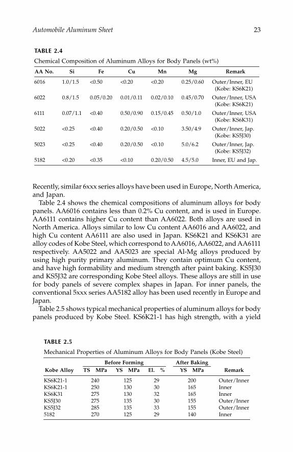
Table 2.4 shows the chemical compositions of aluminum alloys for bodypanels. AA6016 contains less than 0.2% Cu content, and is used in Europe.AA6111 contains higher Cu content than AA6022. Both alloys are used inNorth America. Alloys similar to low Cu content AA6016 and AA6022, andhigh Cu content AA6111 are also used in Japan. KS6K21 and KS6K31 arealloy codes of Kobe Steel, which correspond to AA6016, AA6022, and AA6111respectively. AA5022 and AA5023 are special Al-Mg alloys produced byusing high purity primary aluminum. They contain optimum Cu content,and have high formability and medium strength after paint baking. KS5J30and KS5J32 are corresponding Kobe Steel alloys. These alloys are still in usefor body panels of severe complex shapes in Japan. For inner panels, theconventional 5xxx series AA5182 alloy has been used recently in Europe andJapan.
Table 2.5 shows typical mechanical properties of aluminum alloys for bodypanels produced by Kobe Steel. KS6K21-1 has high strength, with a yield
TABLE 2.4
Chemical Composition of Aluminum Alloys for Body Panels (wt%)
AA No. Si Fe Cu Mn Mg Remark
6016 1.0/1.5
<
0.50
<
0.20
<
0.20 0.25/0.60 Outer/Inner, EU(Kobe: KS6K21)
6022 0.8/1.5 0.05/0.20 0.01/0.11 0.02/0.10 0.45/0.70 Outer/Inner, USA(Kobe: KS6K21)
6111 0.07/1.1
<
0.40 0.50/0.90 0.15/0.45 0.50/1.0 Outer/Inner, USA(Kobe: KS6K31)
5022
<
0.25
<
0.40 0.20/0.50
<
0.10 3.50/4.9 Outer/Inner, Jap.(Kobe: KS5J30)
5023
<
0.25
<
0.40 0.20/0.50
<
0.10 5.0/6.2 Outer/Inner, Jap.(Kobe: KS5J32)
5182
<
0.20
<
0.35
<
0.10 0.20/0.50 4.5/5.0 Inner, EU and Jap.
TABLE 2.5
Mechanical Properties of Aluminum Alloys for Body Panels (Kobe Steel)
Before Forming
After BakingKobe Alloy TS MPa YS MPa El. % YS MPa Remark
KS6K21-1 240 125 29 200 Outer/InnerKS6K21-1 250 130 30 165 InnerKS6K31 275 130 32 165 InnerKS5J30 275 135 30 155 Outer/InnerKS5J32 285 135 33 155 Outer/Inner5182 270 125 29 140 Inner
IP155_C002.fm Page 23 Monday, December 31, 2007 4:49 PM
24
Automotive Engineering: Lightweight, Functional, and Novel Materials
strength of 200 MPa after paint baking, and is in use for many body panelsin Japan. However, the formability of KS6K21-1 is inferior to that of KS5J32.On the other hand, KS5J32 has higher elongation than KS6K21-1.
Increasing Aluminum Body Panel Usage
In order to promote the adoption of aluminum body panels, it is necessaryto provide for the potential panel shapes and the low-cost materials requiredby automobile manufacturers. It is important to improve material propertiesas well as forming and joining technologies, so as to be able to manufacturesuitable body panel shapes. On the other hand, it is necessary to minimizethe number of manufacturing processes, and to be able to use recycledaluminum alloys to ensure a low-cost material.
Aluminum Alloys
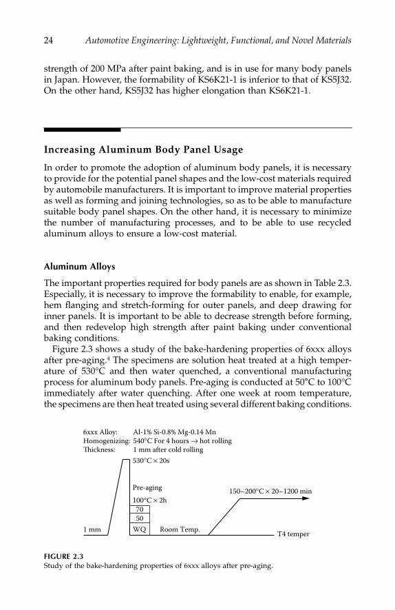
The important properties required for body panels are as shown in Table 2.3.Especially, it is necessary to improve the formability to enable, for example,hem flanging and stretch-forming for outer panels, and deep drawing forinner panels. It is important to be able to decrease strength before forming,and then redevelop high strength after paint baking under conventionalbaking conditions.
Figure 2.3 shows a study of the bake-hardening properties of 6xxx alloysafter pre-aging.
4
The specimens are solution heat treated at a high temper-ature of 530°C and then water quenched, a conventional manufacturingprocess for aluminum body panels. Pre-aging is conducted at 50
°
C to 100°Cimmediately after water quenching. After one week at room temperature,the specimens are then heat treated using several different baking conditions.
FIGURE 2.3
Study of the bake-hardening properties of 6xxx alloys after pre-aging.
6xxx Alloy: Al-1% Si-0.8% Mg-0.14 MnHomogenizing: 540°C For 4 hours → hot rollingThickness: 1 mm after cold rolling
1 mm
530°C × 20s
100°C × 2h7050
WQ Room Temp.
150~200°C × 20~1200 min
T4 temper
Pre-aging
IP155_C002.fm Page 24 Monday, December 31, 2007 4:49 PM
Automobile Aluminum Sheet
25
The pre-aged specimens have high strength after paint baking at lowtemperature for a short time compared with more conventional specimens.The improved bake-hardening properties are caused by fine precipitatesof
β
’
−
Mg
2
Si. This study is important in indicating how to improve thematerial properties.
Forming Technology
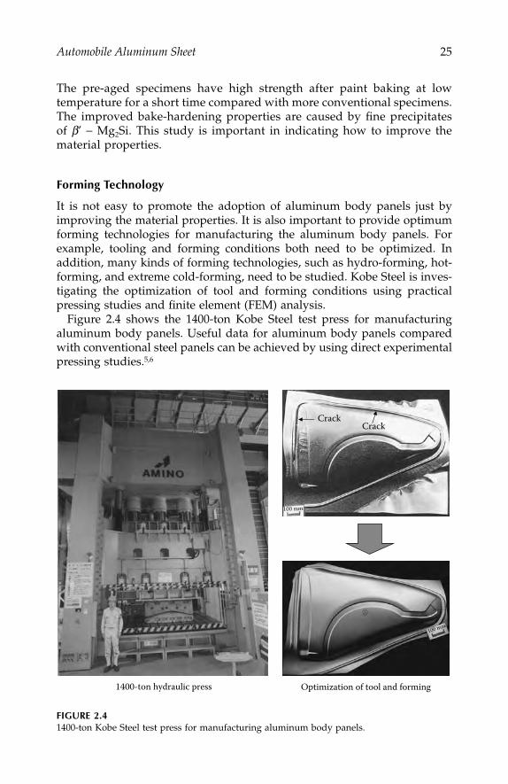
It is not easy to promote the adoption of aluminum body panels just byimproving the material properties. It is also important to provide optimumforming technologies for manufacturing the aluminum body panels. Forexample, tooling and forming conditions both need to be optimized. Inaddition, many kinds of forming technologies, such as hydro-forming, hot-forming, and extreme cold-forming, need to be studied. Kobe Steel is inves-tigating the optimization of tool and forming conditions using practicalpressing studies and finite element (FEM) analysis.
Figure 2.4 shows the 1400-ton Kobe Steel test press for manufacturingaluminum body panels. Useful data for aluminum body panels comparedwith conventional steel panels can be achieved by using direct experimentalpressing studies.
5,6
FIGURE 2.4
1400-ton Kobe Steel test press for manufacturing aluminum body panels.
Optimization of tool and forming1400-ton hydraulic press
CrackCrack
IP155_C002.fm Page 25 Monday, December 31, 2007 4:49 PM

26
Automotive Engineering: Lightweight, Functional, and Novel Materials
On the other hand, Figure 2.5 shows the relationship between finite ele-ment analysis and practical press forming.
7
The prediction of cracks usingfinite element analysis corresponds with the results of cracks occurring dur-ing experimental press forming. The precision of finite element analysis willimprove with increased applications, and this will play an increasing role inpromoting adoption of aluminum panels.
Recycling
Aluminum alloys have excellent recycling properties. It is well-known thatused aluminum beverage cans can be returned to new beverage cans. InJapan in 2001, the recovery ratio of used aluminum beverage cans was 83%,with a can-to-can ratio of 68%, the rest being used mainly for castings.Recycling of aluminum alloys is useful for reducing the cost of the aluminummaterial, and leads to improved life-cycle assessment. Therefore, the reuseof aluminum alloy body panels needs to be studied. In the case of alumi-num press scrap, aluminum manufacturers can reproduce the same alloysheets. However, in the case of aluminum scrap from a scrapped car, it isnot easy to recover the same alloy sheet, because of the mixing of differentalloys, such as 6xxx, 5xxx, and Al-Si series alloys, and different metals, suchas aluminum and steel. Therefore, aluminum manufacturers have to workon alloy designs suitable for recycling and construction of a viable recyclingsystem. The final target will be car-to-car.
Figure 2.6 shows the effect of using an aluminum Audi ASF car on savingenergy. Energy saving from an all-aluminum car will be excellent comparedwith conventional steel cars, with the introduction of recycled aluminumalloys.
FIGURE 2.5
Relationship between finite element analysis and practical press forming.
Necking
12
3
Crack
Crack
(Trunk lid inner)
Prediction of cracksusing FEM analysis
Cracks occurred by practicalpress forming
1
2
3
IP155_C002.fm Page 26 Monday, December 31, 2007 4:49 PM

Automobile Aluminum Sheet
27
Summary
The use of aluminum body panels and recycled aluminum alloys leads toweight reduction in car bodies. Therefore, the promotion of the adoption ofaluminum body panels is very important in both automobile and aluminummanufacturing industries.
References
1. Minato, K.,
Journal of Society of Automotive Engineers of Japan
, 54–9, 2000, 11.2. Winterkorn, Martin et al.,
ATZ
, Vol. 101, 24, 1999.3. Leitermann, Wulf et al.,
Sonderausgabe von ATZ und MTZ (Audi A2)
, 68.4. Sakurai, T.,
The ’87 conference of Japan Institute of Light Metals
, 185.5. Noda, K.,
The ’97 conference of Japan Institute of Light Metals
, 167.6. Yoshida, M
., The ’89 conference of Japan Institute of Light Metals
, 159.7. Konishi, H.,
The proceedings of the 1999 Japanese Spring Conference for the Technologyof Plasticity
, 347.
FIGURE 2.6
Effect of using an aluminium Audi ASF car on saving energy.
<Production> <In service>
Mileage50,000 km 100,000 km 150,000 km
Audi Space Frame ASF (Primary aluminum)
Energy conservation with all subsequentweight reduction (Primary aluminum)
Audi Space Frame ASF(Recycled aluminum)Energy conservation
with all subsequent weight reduction (Recycled aluminum)
Ener
gy b
alan
cest
artin
g po
int:
Conv
entio
nal s
teel
bod
y
0
10
–10
–20
–30
–40
(MW
h)
IP155_C002.fm Page 27 Monday, December 31, 2007 4:49 PM

IP155_C002.fm Page 28 Monday, December 31, 2007 4:49 PM
29
3
Plastic Technology for Automotive Modules
Kazuhisa Toh
CONTENTS
Introduction ...........................................................................................................29Modularization Methods.....................................................................................30Module Carrier Requirements............................................................................30Development Trends ............................................................................................30
Plastic/Steel Hybrid....................................................................................31Long Fiber Thermoplastic (LFT) ...............................................................31Stamping Mold.............................................................................................31Injection-Molded Polypropylene Reinforced by Long Glass Fibers ...31New Materials ..............................................................................................32New Processes..............................................................................................32Applications and Benefits ..........................................................................32
Future Technology ................................................................................................33Future Materials...........................................................................................33
Nanocomposites ..............................................................................33High-Strength Plastic Reinforced by Liquid
Crystal Polymers (LCP) ...................................................33Future Processing Techniques ...................................................................34
Summary ................................................................................................................35References...............................................................................................................35
Introduction
Modularization in the automotive industry is a production method that regardsplural parts as a single part by consolidating them into a single functional unit.This chapter describes trends in automotive modularization and the associateduse of plastic materials and molding processes for module carriers.
IP155_C003.fm Page 29 Monday, December 31, 2007 4:50 PM
30
Automotive Engineering: Lightweight, Functional, and Novel Materials
European automotive makers have been adopting modular parts mainlyfor reasons of cost saving since the late 1980s. In Japan, this kind of modu-larization has not been developed because of insufficient cost benefit.Recently, some Japanese automotive makers have begun to adopt modularparts for cost and weight savings by applying better materials and processesto module carriers. High-performance materials such as sheet molding com-pound (SMC) or glass mat reinforced polypropylene (PP) are normally usedfor module carriers because it is necessary to sustain several surroundingparts. Instead of these materials, new materials and processes have beendeveloped and have achieved dramatic cost and weight savings in the result-ing modular parts. This chapter also describes further new technologies, suchas nanocomposites, which are expected to be used for future module carriers.
Modularization Methods
The subassembly in the body assembly line has been used in Japan since the1970s to shorten the length of the main line. Recently, “function integratedmodules” were introduced to reduce the cost and weight of parts by con-solidating them and integrating their functions.
Module Carrier Requirements
Module carriers are the foundation for assembling surrounding plural parts.Mechanical properties such as good strength, stiffness, impact strength, dura-bility, dimensional stability, etc., are all required not just in the module carrieritself, but also after assembly with the surrounding parts. High-performancematerials are, therefore, needed to manufacture module carriers.
Development Trends
Sheet molding compound and glass mat reinforced polypropylene have beenthe main materials used for module carriers since the late 1980s. Both mate-rials are reinforced by glass fibers, have high strength and good dimensionalstability, and can meet the requirements for module carriers. However, a semi-finishing product step is required after compression molding, and design flex-ibility is not so high. Moreover, sheet molding compound cannot easily berecycled because of the presence of thermosetting resin. In order to improve
IP155_C003.fm Page 30 Monday, December 31, 2007 4:50 PM

Plastic Technology for Automotive Modules
31
these characteristics, new materials and processes have been developed, asdiscussed below.
Plastic/Steel Hybrid
In late 1997, a European automotive maker introduced a plastic/steel hybridstructure for a front-end module carrier consisting of injection molded poly-amide (PA) and steel reinforcement. The strength of an injection-molded partis normally lower than that of a compression-molded part. In this case, how-ever, the steel part of the component was effective in enhancing the strength.The difference between a hybrid part and a conventional compression-molded part is the need for a semi-finishing product step. The hybrid partdoes not need post-finish treatment because of the injection molding. Accord-ing to a material supplier, hybrid structures can reduce cost and weight by10% each, compared with compression-molded parts.
Long Fiber Thermoplastic (LFT)
A European automotive maker introduced long fiber thermoplastics tech-nology in 1998. First, an intermediate product consisting of polypropyleneand 25–80mm glass fibers in length is produced with an extruder. Then, theintermediate product is charged into a molding die and compressionmolded. This material can be used with a complex design and is also easilyrecyclable compared to conventional glass mat reinforced polypropylene.
1
Stamping Mold
The melted resin from the extruder head is directly charged into the die. Then,the material is compression molded. The molded part has low warpage andhigh-design flexibility. A front-end carrier using this technology is 30%lighter than a conventional steel part. In 2001, a Japanese automotive makerintroduced this technology.
2
Injection-Molded Polypropylene Reinforced by Long Glass Fibers
Injection-molded module carriers have been developed since the early1990s. In 2002, a Japanese automotive maker introduced injection-moldedcarriers without steel reinforcement. This system has then been applied toa front-end module and door module carriers for a worldwide series ofproduction cars.
A semi-finishing product step is not necessary for an injection-moldedpart. In addition, injection-molded parts have a high level of design flexibility.However, injection-molded strength is lower than for conventional glass matreinforced polypropylene because the length of the glass fibers is shortened
IP155_C003.fm Page 31 Monday, December 31, 2007 4:50 PM
32
Automotive Engineering: Lightweight, Functional, and Novel Materials
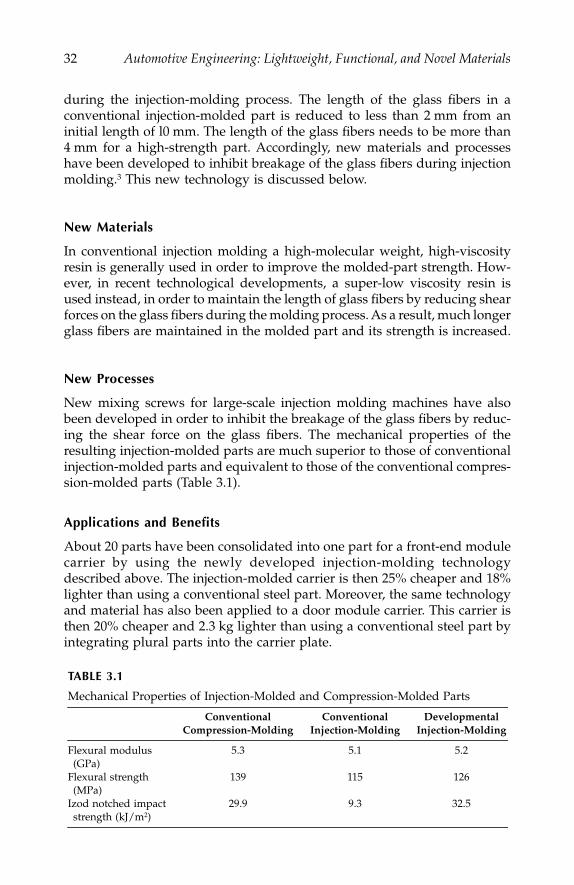
during the injection-molding process. The length of the glass fibers in aconventional injection-molded part is reduced to less than 2 mm from aninitial length of l0 mm. The length of the glass fibers needs to be more than4 mm for a high-strength part. Accordingly, new materials and processeshave been developed to inhibit breakage of the glass fibers during injectionmolding.
3
This new technology is discussed below.
New Materials
In conventional injection molding a high-molecular weight, high-viscosityresin is generally used in order to improve the molded-part strength. How-ever, in recent technological developments, a super-low viscosity resin isused instead, in order to maintain the length of glass fibers by reducing shearforces on the glass fibers during the molding process. As a result, much longerglass fibers are maintained in the molded part and its strength is increased.
New Processes
New mixing screws for large-scale injection molding machines have alsobeen developed in order to inhibit the breakage of the glass fibers by reduc-ing the shear force on the glass fibers. The mechanical properties of theresulting injection-molded parts are much superior to those of conventionalinjection-molded parts and equivalent to those of the conventional compres-sion-molded parts (Table 3.1).
Applications and Benefits
About 20 parts have been consolidated into one part for a front-end modulecarrier by using the newly developed injection-molding technologydescribed above. The injection-molded carrier is then 25% cheaper and 18%lighter than using a conventional steel part. Moreover, the same technologyand material has also been applied to a door module carrier. This carrier isthen 20% cheaper and 2.3 kg lighter than using a conventional steel part byintegrating plural parts into the carrier plate.
TABLE 3.1
Mechanical Properties of Injection-Molded and Compression-Molded Parts
ConventionalCompression-Molding
ConventionalInjection-Molding
DevelopmentalInjection-Molding
Flexural modulus (GPa)
5.3 5.1 5.2
Flexural strength(MPa)
139 115 126
Izod notched impactstrength (kJ/m
2
)29.9 9.3 32.5
IP155_C003.fm Page 32 Monday, December 31, 2007 4:50 PM

Plastic Technology for Automotive Modules
33
Future Technology
Modularization will be further promoted and expanded by improvingmechanical properties, surface quality, recyclability, etc., of the module car-rier. The potential technology that will be able to meet these requirementsis discussed below.
Future Materials
Nanocomposites
The mineral clay is attracting attention as a reinforcement filler for injection-molded polyamide parts, enhancing the part strength considerably morethan conventional fillers such as glass fibers. The aspect ratio of the nanoscaleclay particles vary from several hundreds to several thousands—very highcompared to conventional glass fiber filler. The resulting injection-moldednanocomposite polyamide materials show unique characteristics. Theirstrength and stiffness at high temperature are dramatically improved at thesame time as maintaining the chemical resistance, paintability, surfaceappearance, etc., that are important polyamide material characteristics.
4
Polyamide nanocomposites are expected to be applied to module carriersfor a range of visible parts. Polypropylene nanocomposites are also beingresearched. It is reported that 4.5% polypropylene/clay nanocompositeshave strengths equivalent to 20% talc-reinforced polypropylene.
5
High-Strength Plastic Reinforced by Liquid Crystal Polymers (LCP)
6
Thermoplastic resins are generally recyclable or can be reused for similarapplications. However, resins reinforced by glass fibers lose their perfor-mance after the granulating process in recycling because of the damagesustained by the reinforcing fibers. An important development target is toincrease the strength of the polymer composite and make it even easier torecycle. Composites have been prepared using a generic twin-screw extruderto blend liquid crystal polymers with thermoplastic resin, with extrusionconditions such as shear rate at the die set to cause fibril formation. Theliquid crystal polymer, polypropylene, and compatibilizer are mixed initiallyin pellet form, and then extruded in a composite film with the polypropylenereinforced by liquid crystal polymer fibrils in the extrusion direction. Thesefilms are pre-heated and laminated to produce a moldable blank with goodmoldability, and compression-molded samples exhibit good mechanicalproperties. The stiffness of a bumper beam prototype made of polypropyl-ene/liquid crystal polymer is equivalent to a conventional glass mat rein-forced polypropylene material. Figure 3.1 shows load-displacement curvesfor equivalent polypropylene/liquid crystal polymer and the glass mat rein-forced polypropylene bumper beams.
IP155_C003.fm Page 33 Monday, December 31, 2007 4:50 PM

34
Automotive Engineering: Lightweight, Functional, and Novel Materials
The recyclability of the liquid crystal polymer composites is shown inFigure 3.2. Even after being recycled ten times, the tensile strength is equiv-alent to that of the virgin material. At present, the price of liquid crystalpolymer is about ten times that of glass fiber; however, cost reductions areexpected to be achieved by expanding applications to the automotiveindustry.
Future Processing Techniques
Microcellular plastic is manufactured by a new molding process, withimproved mechanical and thermal properties compared with conventionalfoam plastics. The key characteristics of the microcellular plastic material
7
are the cell size, in the range 0.1 to 10
μ
m, and the cell number density, inthe range 10
9
to 10
15
cells/cm
3
. A saturated polymer gas solution is brought
FIGURE 3.1
Load-displacement curves for injection-molded polypropylene/liquid crystal polymer andcompression-molded glass mat reinforced polypropylene composites.
FIGURE 3.2
Tensile strength versus recycling time for a polypropylene/liquid crystal polymer composite.
Compression-moldedglass mat reinforced PP
LCP/PP
Displacement (mm)
Load
(kN
)
5040
30
20
10
00 10 20 30 40 50
Tens
ile S
tren
gth
(MPa
)
Repeated Recycling (times of repetition)
Virgin 1 2 3 4 5 6 10
100
75
50
25
0
IP155_C003.fm Page 34 Monday, December 31, 2007 4:50 PM

Plastic Technology for Automotive Modules
35
into a thermodynamically unstable state, where decompression and/or heat-ing instantaneously reduce the gas solubility and leads to formation of themicrocells. Carbon dioxide (CO
2
) or nitrogen (N
2
) gas is usually used toreduce environmental dangers. The resulting characteristics of the foamedplastics:
8
Low warpageLow clamping force on the molding machine (i.e., low injection pressure)Easy to mold large partsShort molding cycle time
At present, this new process has some technical issues such as poor surfaceappearance caused by flow marks. However, in the future, the new manu-facturing technology can be expected to be used to mold large-scale partswith complex designs, at low cost and weight. These characteristics will bevery useful for future module parts.
Summary
This chapter has described materials and processes for a module carrier.Other techniques, such as bonding and computer-aided design, are also veryimportant for automotive modules. By combining the different techniquescarefully, plastic technology will contribute strongly toward the develop-ment of future automotive modules.
References
1. Nikkei Mechanical, 1998, Vol. 12, No. 531, 17.2. Tachibana, M., et al., “Plastic Bolster (Radiator Core Support),”
Nissan TechnicalReview
, No. 50, 47–50, 2002.3. Tochioka, T., et al., “Development of module carriers by injection molding with
glass fiber reinforced polypropylene,”
JSAE
, No. 31-02, 5–8, 2002.4. Ogami, A.,
JSPP
, No l. 14, No. 4, 217–221, 2002.5. SPE Automotive TPO Global Conference, 1999.6. Sasaki, K., et al., “High-strength Plastic Reinforcement by Liquid Crystal
Polymers,”
FSITA '96
, M0 6.04, 1996.7. Baldwin, D., et al., Suh, N. P., Polym. Proc., 1994, 6, 187, 245, 1994.8. Tsuda, F.,
JSPP
, Vol. B., No. 2, 83–87, 2001.
IP155_C003.fm Page 35 Monday, December 31, 2007 4:50 PM

IP155_C003.fm Page 36 Monday, December 31, 2007 4:50 PM

Section 2
Functional Materials
Functional materials, those materials that have electronic, optical, or magneticproperties, are an essential part of the modern automobile. Functional mate-rials are not only deployed in the primary structures and drive systems butalso in the safety systems and in telematic and entertainment systems, whichoften provide the key product differentiation features and can yield a highadded value for the manufacturers. This section outlines the application offunctional materials in five representative areas of automotive technology:
• Combustion sensors• Controlled rheology fluids for mechanical linkages• Engineered crash structures• Engine control and drive sensor electronics• Smart structures
The authors review the current state of the art and project future applicationareas where functional materials and smart technologies will make signifi-cant impact on automotive design and manufacture.
IP155_S002.fm Page 1 Monday, December 10, 2007 4:14 PM

IP155_S002.fm Page 2 Monday, December 10, 2007 4:14 PM

39
4
Automotive Catalysts
Michael Bowker
CONTENTS
Introduction ...........................................................................................................39The Development of Automotive Catalysts.....................................................39Important Factors in Pollution Removal ..........................................................40
Light-Off Temperature ................................................................................40Lean-Burn Engines ......................................................................................43Diesel .............................................................................................................44
NSR Catalysts ........................................................................................................44Summary ................................................................................................................48References...............................................................................................................48
Introduction
Pollution is not a new phenomenon, and probably existed in the most ancientof times. Indeed, legislation was enacted many centuries ago in different partsof the world. For instance, in England, in the thirteenth century, King EdwardI issued edicts aimed at preventing the sulphurous local pollution in Londondue to coal burning. Most pollution events in the world since then have beenassociated with the use of fossil fuels, and this is still the source of manyproblems today. Types of pollution that are topical are given in Table 4.1.Much pollution in recent times has come from the ever-expanding use of cars,and the amelioration of this pollution problem is the subject of this chapter.
The Development of Automotive Catalysts
Pollution was not perceived as a problem during the first few decades of theuse of automobiles, due to their relative rarity and, therefore, the low totalpollution burden on the atmosphere, notwithstanding the fact that early vehicles
IP155_C004.fm Page 39 Tuesday, January 8, 2008 3:00 PM

40
Automotive Engineering: Lightweight, Functional, and Novel Materials
were inefficient. However, with the buildup of car ownership in the world, thepollution load increased until the effect became severe and noticeable. This wasrecognized first in the Los Angeles basin due to a combination of local factors,but most importantly due to the high earning power of the local populationand, therefore, the high per capita car ownership. Smogs occurred in the late1950s and 60s, which were basically due to emissions from cars that interactedtogether in the presence of intense sunlight to produce photochemical smogs.The major polluting components were nitrogen oxides (NO
x
), ozone O
3
, andhydrocarbons together with highly damaging partially oxidized products. Oneexample of these—peroxy acetyl nitrate (PAN)—is detrimental to the lungs inppb concentrations, and is an eye irritant. Many deaths resulted from suchsmogs, mainly among the elderly, infirm, or those with existing lung problems.
Finally, the California legislature decided that the problem must be solvedand that it could only be achieved in a mandatory way. At first, this wasdesigned to restrict carbon monoxide and hydrocarbon emissions. Later,NO
x
was included in the legislation. Initially, the U.S. car companies opposedsuch legislation. However, a catalyst cure for the problem was not onlypossible, but was achieved and demonstrated for a production model car. Aschematic illustration of the form of a car catalyst currently used is given inFigure 4.1. This is a ceramic monolith that is strong, resistant to thermalshock, and the active phases are present on this monolith inside a highlyporous, but thin layer of washcoat, which is usually mainly alumina. Moreextensive reviews of this technology are available.
1
From this point in time, the legislators were encouraged to push the sci-entists to ever-greater improvements of catalytic efficiency by increasing thestringency of legislation. The development of this legislation is illustrated inTable 4.2. It is now the case that catalysts, at least for normally aspiratedpetrol engines, are very efficient. The current and future challenges to auto-motive pollution removal are outlined below.
Important Factors in Pollution Removal
Light-Off Temperature
Pollutant emission has to meet the strict legislative levels shown in Table 4.2.These limits are set to get tougher. If the pollutants emitted from the engine
TABLE 4.1
Some Major Environmental Stresses
Environmental Symptom Likely Cause
Tropospheric pollution, smogs, etc. Fossil fuel overconsumptionAcid rain Fossil fuel overconsumptionGlobal warming Fossil fuel overconsumptionOzone hole Chlorofluoro
–
carbon emissionsDecreased male fertility Groundwater pollution
IP155_C004.fm Page 40 Tuesday, January 8, 2008 3:00 PM
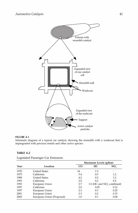
Automotive Catalysts
41
FIGURE 4.1
Schematic diagram of a typical car catalyst, showing the monolith with a washcoat that isimpregnated with precious metals and other active species.
TABLE 4.2
Legislated Passenger Car Emissions
Maximum Levels (g/Km)Year Location CO HC NO
x
1970 United States 14 1.3 -1975 California 5.4 0.5 1.21980 United States 4.2 0.2 1.21993 California 2.0 0.2 0.21993 European Union 2.7 1.0 (HC and NO
x
combined)1997 California 2.0 0.05 0.121997 European Union 2.3 0.3 0.252001 European Union 2.3 0.2 0.152005 European Union (Proposed) 1.0 0.1 0.08
Exhaust withmonolith catalyst
Expanded viewof one catalyst
cell
Expanded viewof the washcoat
Active catalystparticles
Support
Monolith wall
Washcoat
IP155_C004.fm Page 41 Tuesday, January 8, 2008 3:00 PM

42
Automotive Engineering: Lightweight, Functional, and Novel Materials
are accumulated and analyzed, they follow the pattern schematically shownin Figure 4.2,
2
that is, the vast majority of the pollutants are emitted shortlyafter engine switch-on, while very little pollution is produced once theexhaust region is hot. This is because the catalyst has to be hot to be able toconvert the pollutants (see, for example, carbon monoxide oxidation by asupported platinum catalyst is Figure 4.3). Thus, even if the engine isswitched off for a short while and restarted, then little pollution is producedbecause the catalyst is still at elevated temperature (so-called “warm start”)and is immediately effective upon restart.
Thus, reducing the temperature for light-off to occur is a major targetfor pollutant reduction, and this requires the development of more activecatalytic materials. One way to get light-off to occur more quickly withoutactivity enhancement is to place a catalyst in the engine manifold, closeto the source of pollution, since this gets hot more quickly than the normalposition farther down the exhaust pipe. This approach is carried out now-adays. Another option being seriously investigated by a number of com-panies is the use of a plasma discharge prior to the normal catalyst thatproduces activated species that particularly enhance NO
x
destruction.Also, artificial gas heaters in the car exhaust prior to the catalyst have beenconsidered, but these use a significant amount of power from the engine.
There are hopes for more active catalysts that light-off at much lowertemperatures than platinum, and one example of this comes from a surpris-ing element, namely gold. Thought previously to be inactive, it has beenshown that gold nanoparticles are very active for carbon monoxide oxida-tion, even at room temperature, when prepared in the correct way.
3
FIGURE 4.2
An illustration of the total amount of emitted pollutants collected from a car exhaust afterengine switch-on from a cold start, and after switching off for only a short period of timefollowed by restart (warm start). Most of the pollution is produced within the first minutes ofthe engine is switching on, due to inefficiency of the catalyst at low temperatures.
Totalemitted
pollutants
Time
Coldstart
Warmstart
IP155_C004.fm Page 42 Tuesday, January 8, 2008 3:00 PM

Automotive Catalysts
43
Lean-Burn Engines
Lean-burn engines have been introduced because they are more fuel-efficientand therefore produce less carbon dioxide burden on the atmosphere,besides being more economically efficient for the user and reducing the rateof loss of fossil fuel stocks. However, although oxidation reactions of hydro-carbons and carbon monoxide occur well under such circumstances, thereduction of NO
x
to nitrogen becomes very inefficient. Therefore, new cata-lytic strategies are needed.
One of these strategies involves the use of a NO
x
storage medium in thecatalyst, and catalysts based on barium oxide BaO have been developedsuccessfully by Toyota.
4,5
In this situation, when the active metal componentis deactivated by becoming saturated with oxygen atoms at the surface, itno longer dissociates NO efficiently. The NO
x
is then stored on BaO as thenitrate. Periodically, a reductant (fuel) is injected over the catalyst and thisreduces the metal surface so that it becomes active in the direct sense ofcatalyzing pollutants in the exhaust gas, but it also catalytically decomposesthe nitrate and cracks the resulting NO
x
to give nitrogen (and oxidizedproducts such as carbon dioxide and water). The effect of the storage mediumis shown schematically in Figure 4.4 and results in significantly enhancedNO
x
conversion. The details of this catalysis are presented further below.
FIGURE 4.3
A plot showing the light-off for carbon monoxide oxidation occurring at about 180˚C for asupported platinum catalyst. There is zero conversion below about 150˚C.
100 200 300Temperature (°C)
0
50
100
Conv
ersio
n (%
)“Light-off ”
IP155_C004.fm Page 43 Tuesday, January 8, 2008 3:00 PM

44
Automotive Engineering: Lightweight, Functional, and Novel Materials
Diesel
Diesel is a type of lean-burn engine and so some of the above strategies canbe used on exhausts of this type. However, a major problem here is that ahigh level of soot particles are produced from the engine that tend to blockand degrade the catalyst since they are not easily removed themselves.Johnson
–
Matthey in the United Kingdom recently won the MacRobertAward from the Royal Academy of Engineering for their development ofthe CRT (continuously regenerating trap) particulate removal technology.This is a technology that uses a porous-walled monolith to store the partic-ulates where they are attacked and oxidized by nitrogen dioxide NO
2
pro-duced in an initial catalytic oxidation step.
6
NSR Catalysts
NO
x
storage and reduction (NSR) catalysts have a function for binding NO
x
during lean running. Figure 4.4 shows schematically the effect of
inclusionof
barium oxide in such catalysts. As a result of
operation with a periodicreduction pulse, significantly more
NO
x
is converted than would otherwisebe the case.
FIGURE 4.4
Schematic illustration of the NO
x
conversion process in NSR catalysts. NO
x
is stored during thelean operation and is then removed from the catalyst and converted to nitrogen by injection ofa short pulse of fuel that chemically reduces metal part of the catalyst that activates it for NO
x
destruction.
NOx Level out of engine
0.05 seconds
With NOx storagecompound
Without NOx storagecompound Reductant injection
Reductant off
Time
IP155_C004.fm Page 44 Tuesday, January 8, 2008 3:00 PM

Automotive Catalysts
45
Experiments currently underway at the University of Reading, usinghydrogen as the reductant, clearly show the beneficial effect of barium. InFigure 4.5 a pulse of NO is made into a continuous flow of oxygen in heliumupon a catalyst that had already been dosed with several pulses of NO.Apart from some displacement of oxygen from the flow, when NO is pulsedthere is no net NO uptake on the catalyst and no products are observed.This is because the catalyst is fully saturated with nitrate already under theseconditions and the platinum surface is saturated with oxygen atoms, whichprevents NO dissociation and barium nitrate decomposition. When a hydro-gen pulse is introduced, then there is immediate consumption of the hydro-gen with coincident decomposition of the stored NO
x
, and a large amountof nitrogen is produced. This is because the platinum is reduced by thehydrogen pulse, adjacent barium nitrate is decomposed to NO + O
2
, and theplatinum cracks the NO in the following way:
2NO
−
7N
2
+
20
a
FIGURE 4.5
Showing a pulsed-flow reactor experiment relating to NO
x
storage and reduction on a Pt/BaO/Al
2
0
3
catalyst. NO (30 amu) is periodically pulsed into a continuous flow of oxygen over thecatalyst held at 300˚C. The first pulse, shown at 22.5 minutes, is just one of many that the catalysthad previously received, and so it is saturated with nitrate and the whole of the input NO pulseis detected at the reactor outlet. The dip in oxygen (32 amu) here is simply due to displacementfrom the gas phase by the NO injection, it does not signify reaction. At
−
23.1 minutes a pulseof hydrogen is injected over the catalyst, which results in reduction of the metal component,and thus considerable extra uptake of oxygen. At the same time a large amount of nitrogen (28and 14 amu) is evolved due to the catalyzed decomposition of the Ba(NO
3
)
2
to form BaO. Uponsubsequently admitting a pulse of NO at 23.6 minutes, there is uptake of both NO and oxygen(compare the pulse at 23.6 mins with that at 22.5 mins) as decomposed barium nitrate isreformed.
N–14H2–2N2–28NO–30O2–32N2O–44NO2–46
23.523.022.5Time (mins)
Mas
s spe
c. in
tens
ity (a
rb. u
nits
)
IP155_C004.fm Page 45 Tuesday, January 8, 2008 3:00 PM
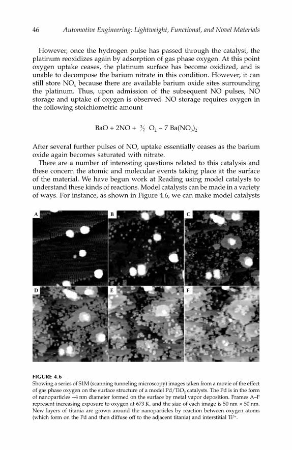
46
Automotive Engineering: Lightweight, Functional, and Novel Materials
However, once the hydrogen pulse has passed through the catalyst, theplatinum reoxidizes again by adsorption of gas phase oxygen. At this pointoxygen uptake ceases, the platinum surface has become oxidized, and isunable to decompose the barium nitrate in this condition. However, it canstill store NO
x
because there are available barium oxide sites surroundingthe platinum. Thus, upon admission of the subsequent NO pulses, NOstorage and uptake of oxygen is observed. NO storage requires oxygen inthe following stoichiometric amount
BaO
+
2NO
+
O
2
−
7 Ba(NO
3
)
2
After several further pulses of NO, uptake essentially ceases as the bariumoxide again becomes saturated with nitrate.
There are a number of interesting questions related to this catalysis andthese concern the atomic and molecular events taking place at the surfaceof the material. We have begun work at Reading using model catalysts tounderstand these kinds of reactions. Model catalysts can be made in a varietyof ways. For instance, as shown in Figure 4.6, we can make model catalysts
FIGURE 4.6
Showing a series of S1M (scanning tunneling microscopy) images taken from a movie of the effectof gas phase oxygen on the surface structure of a model Pd/TiO
2
catalysts. The Pd is in the formof nanoparticles ~4 nm diameter formed on the surface by metal vapor deposition. Frames A–Frepresent increasing exposure to oxygen at 673 K, and the size of each image is 50 nm
×
50 nm.New layers of titania are grown around the nanoparticles by reaction between oxygen atoms(which form on the Pd and then diffuse off to the adjacent titania) and interstitial Ti
3+
.
32
A
D E F
B C
IP155_C004.fm Page 46 Tuesday, January 8, 2008 3:00 PM
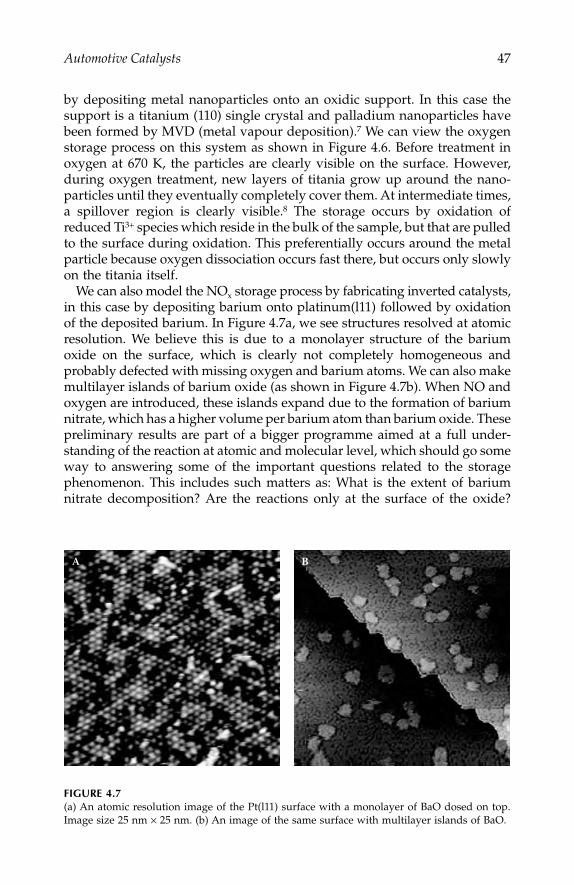
Automotive Catalysts
47
by depositing metal nanoparticles onto an oxidic support. In this case thesupport is a titanium (110) single crystal and palladium nanoparticles havebeen formed by MVD (metal vapour deposition).
7
We can view the oxygenstorage process on this system as shown in Figure 4.6. Before treatment inoxygen at 670 K, the particles are clearly visible on the surface. However,during oxygen treatment, new layers of titania grow up around the nano-particles until they eventually completely cover them. At intermediate times,a spillover region is clearly visible.
8
The storage occurs by oxidation ofreduced Ti
3+
species which reside in the bulk of the sample, but that are pulledto the surface during oxidation. This preferentially occurs around the metalparticle because oxygen dissociation occurs fast there, but occurs only slowlyon the titania itself.
We can also model the NO
x
storage process by fabricating inverted catalysts,in this case by depositing barium onto platinum(l11) followed by oxidationof the deposited barium. In Figure 4.7a, we see structures resolved at atomicresolution. We believe this is due to a monolayer structure of the bariumoxide on the surface, which is clearly not completely homogeneous andprobably defected with missing oxygen and barium atoms. We can also makemultilayer islands of barium oxide (as shown in Figure 4.7b). When NO andoxygen are introduced, these islands expand due to the formation of bariumnitrate, which has a higher volume per barium atom than barium oxide. Thesepreliminary results are part of a bigger programme aimed at a full under-standing of the reaction at atomic and molecular level, which should go someway to answering some of the important questions related to the storagephenomenon. This includes such matters as: What is the extent of bariumnitrate decomposition? Are the reactions only at the surface of the oxide?
FIGURE 4.7
(a) An atomic resolution image of the Pt(l11) surface with a monolayer of BaO dosed on top.Image size 25 nm
×
25 nm. (b) An image of the same surface with multilayer islands of BaO.
A B
IP155_C004.fm Page 47 Tuesday, January 8, 2008 3:00 PM
48
Automotive Engineering: Lightweight, Functional, and Novel Materials
And what is the nature of the spillover and reverse spillover processes thatare responsible for NO
x
storage and decomposition?
Summary
This chapter has outlined the development of materials and catalysts for theremoval of pollutants from car exhausts. Ways of measuring the catalyticprocesses involved using time resolved methods are described, as also is theapplication of a novel, atomically resolving, imaging technique to improvethe understanding of the processes involved at the surface of the catalyticmaterials.
References
1. See, for instance, E. Lax and B. Engler in “Environmental Catalysis,” ed. G. Ertl
.2. Bowker, M., “The Basis and Applications of Heterogeneous Catalysis,”
OxfordChemistry Primers
, 1998.3. Haruta, M., S. Tsubota, T. Kobayashi, H. Kageyama, M. Genet, and B. Delmon,
J. Catal.
, Vol. 144, 175, 1993.4. Takahashi, N., H. Shinjoh, T. Lijima, T. Suzuki, K. Yamazaki, K. Yokota,
H. Suzuki, S. Matsumoto, T. Tyanizawa, T. Tanaka, S. Tateishi, and K. Kasahara,
Catal. Today
, Vol. 27, 63, 1996.5. Matsumoto, S.,
Catal. Today
, Vol. 29, 43, 1996.6. See, for instance, P.N. Hawker,
PIal. Metals Rev
., Vol. 39, 2, 1995.7. Stone, P., S. Poulston, R. Bennett, and M. Bowker,
J. Chem. Soc. Chem. Comm.
,1369–70, 1998.
8. Bennett, R., P. Stone, and M. Bowker,
Cat. Letts
, Vol. 59, 99
–
106, 1999.
IP155_C004.fm Page 48 Tuesday, January 8, 2008 3:00 PM
49
5
Magnetorheological Fluids
Kevin O’Grady, V. Patel, and S. W. Charles
CONTENTS
Introduction ...........................................................................................................49Historical Developments .....................................................................................50
Electrorheological Fluids ............................................................................50Magnetorheological Fluids.........................................................................51
Structure of Magnetorheological Fluids............................................................51Magnetic Behavior................................................................................................53Rheological Behavior............................................................................................54Electrorheological and Magnetorheological Devices ......................................56Evaluation of a Magnetorheological Damper..................................................57
Damper Test Results—Load versus Velocity ..........................................58Effects of Temperature ................................................................................60
Other Devices ........................................................................................................61Summary ................................................................................................................62References...............................................................................................................62
Introduction
Controllable fluids that change their mechanical properties under the influ-ence of a remote external influence have been known since the mid to late1940s. Broadly speaking, two classes of such materials exist: these are elec-trorheological fluids, which change their rheological behavior under theinfluence of electric fields, and magnetorheological fluids, which changetheir rheology under the influence of magnetic fields. These materials aresimilar to each other in terms of their basic structures in that they are bothcolloidal dispersions of solid particles in a carrier liquid that is usually astandard hydraulic oil. In the case of electrorheological (ER) fluids, the
IP155_C005.fm Page 49 Monday, December 31, 2007 4:52 PM
50
Automotive Engineering: Lightweight, Functional, and Novel Materials
particles used can be starch or other similar materials, whereas in the caseof magnetorheological (Magnetorheological) fluids, the materials used must,of course, be magnetic materials such as particles of iron, cobalt, etc. Bothclasses of material have a significant number of potential applications in theautomotive sector.
Despite the fact that they have been available for many years, the impetusto bring such materials into use has not been great until recently, whenissues of noise pollution, both for passengers in automobiles and for thoseliving near to major arterial roads, have become increasingly important.Also, previous generations of materials have perhaps not been suitable forimmediate application due to a lack of long-term stability in terms of anumber of properties. The application areas are, for the case of dampers,under the seats of heavy vehicles such as lorries, tractors, buses, etc., enginemountings, particularly for vibration and noise suppression in both luxuryvehicles, and for example, coaches and buses. It is also possible to design asimple slip clutch or brake that can be used for control of cooling fans and4-wheel drive differentials. In these cases, the use of a controllable liquidhas major advantages in terms of energy conservation. In non-automotiveapplications, magnetorheological fluids have already found application asgenerators of a variable resistance in exercise machines. They have also beensuggested as an energy-free solution to the problem of maintaining a firedoor in the open position that would subsequently close when a fire alarmis sounded.
Historical Developments
Electrorheological Fluids
Electrorheological fluids were developed in the first instance by Winslowin the mid-1940s.
1
Development continued intermittently from that timewith a surge in activities in the 1980s and early 1990s with many formu-lations being proposed both for the fluids themselves and a wide rangeof devices developed. For a review of these developments, see Scharnhorstand Schelttler-Köhler.
2
The basic structure of the electrorheological fluidswere based upon colloidal dispersions where the interaction between theparticles in the presence of an electric field derived from the presence ofabsorbed ions, or more commonly, water molecules on the surface of thecolloidal particles themselves. The carrier oils were usually the simplehydraulic oils that are used in normal rheological devices. A wide rangeof dispersants appropriate to the particular particles and the carriervehicle were also used.
Modern electrorheological fluids based upon these structures exhibitdynamic yield strengths typically in the range 3
–
5 kPa for electric fieldsof the order of 3
–
5 kV/mm. Unfortunately, given that the basis of the
IP155_C005.fm Page 50 Monday, December 31, 2007 4:52 PM
Magnetorheological Fluids
51
electrorheological effect lies not in a permanent dipole moment but in aninduced moment arising from the presence of ionic species or water mole-cules, this limits the operating temperature of such fluids to the range10
–
90ºC. Nonetheless, for operation in benign environments, such as seatdampers or retarders on exercise devices, such an operating temperaturerange is not preclusive.
Magnetorheological Fluids
Magnetorheological fluids were first reported by Rabinov from the NationalBureau of Standards in the United States in 1948.
3
The original applicationenvisaged was to produce a device such as a slip clutch.
In the case of magnetorheological fluids, the dispersion consists of fine(but not ultra fine) magnetic particles dispersed in oils, again using conven-tional dispersants, but also a number of other ingredients as discussed below.Given a correct formulation for such particles, the dynamic strengths are upto 100 kPa for fluids in fields of 2
–
3 kOe and the temperature range from–40ºC to 150ºC. These figures must be compared to the much lower 3
–
5 kPafor electrorheological fluids. This significantly larger yield stress value formagnetorheological fluids derives from the fact that the net polarizingmoment per unit volume of a magnetic material derives from its bulk,whereas the electrorheological effect derives only from the surface of theparticles and, hence, the effective charge density in the two cases is signifi-cantly different.
However, in contrast, the structure of magnetorheological fluids is ofnecessity more complex. Ideally, it is desirable to use the largest particlespossible since the force between them depends upon the product of theirvolumes. However, in practice, such particles tend to agglomerate irrevers-ibly and normal dispersants are unable to resist the forces of attractionbetween the particles. There are a number of strategies to overcome thisdifficulty, one of which is to use dispersants, which are thixotropic agents,and a number of reports of such materials can be found in the literature,e.g., Weiss et al.
4
An alternative strategy is to incorporate thixotropic agentsinto the dispersion such as clay particles, which prevent the magnetic par-ticles coming into close contact and, hence, prevent irreversible changes inthe microstructure of the material.
Structure of Magnetorheological Fluids
Small magnetic particles in the nanosize range (d < 25 nm) are too small tosupport a normal magnetic domain and, hence, exist in a single domain stateeffectively behaving as tiny permanent bar magnets. The origin of this effectand the critical size for this behavior varies from material to material, but isgenerally well understood.
5
Larger magnetic particles typically of dimension1–100
μ
m contain a number of magnetic domains that are oriented in such
IP155_C005.fm Page 51 Monday, December 31, 2007 4:52 PM
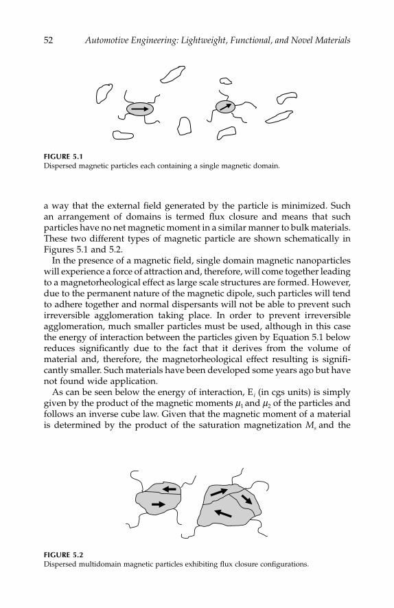
52
Automotive Engineering: Lightweight, Functional, and Novel Materials
a way that the external field generated by the particle is minimized. Suchan arrangement of domains is termed flux closure and means that suchparticles have no net magnetic moment in a similar manner to bulk materials.These two different types of magnetic particle are shown schematically inFigures 5.1 and 5.2.
In the presence of a magnetic field, single domain magnetic nanoparticleswill experience a force of attraction and, therefore, will come together leadingto a magnetorheological effect as large scale structures are formed. However,due to the permanent nature of the magnetic dipole, such particles will tendto adhere together and normal dispersants will not be able to prevent suchirreversible agglomeration taking place. In order to prevent irreversibleagglomeration, much smaller particles must be used, although in this casethe energy of interaction between the particles given by Equation 5.1 belowreduces significantly due to the fact that it derives from the volume ofmaterial and, therefore, the magnetorheological effect resulting is signifi-cantly smaller. Such materials have been developed some years ago but havenot found wide application.
As can be seen below the energy of interaction, E
i
(in cgs units) is simplygiven by the product of the magnetic moments
μ
1
and
μ
2
of the particles andfollows an inverse cube law. Given that the magnetic moment of a materialis determined by the product of the saturation magnetization
M
s
and the
FIGURE 5.1
Dispersed magnetic particles each containing a single magnetic domain.
FIGURE 5.2
Dispersed multidomain magnetic particles exhibiting flux closure configurations.
IP155_C005.fm Page 52 Monday, December 31, 2007 4:52 PM
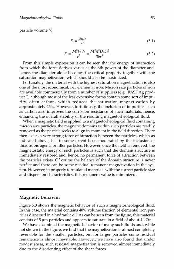
Magnetorheological Fluids
53
particle volume
V
,
(5.1)
(5.2)
From this simple expression it can be seen that the energy of interactionfrom which the force derives varies as the 6th power of the diameter and,hence, the diameter alone becomes the critical property together with thesaturation magnetization, which should also be maximized.
Fortunately, the material with the highest saturation magnetization is alsoone of the most economical, i.e., elemental iron. Micron size particles of ironare available commercially from a number of suppliers (e.g., BASF Ag prod-uct.
6
), although most of the less expensive forms contain some sort of impu-rity, often carbon, which reduces the saturation magnetization byapproximately 25%. However, fortuitously, the inclusion of impurities suchas carbon also improves the corrosion resistance of such materials, hence,enhancing the overall stability of the resulting magnetorheological fluid.
When a magnetic field is applied to a magnetorheological fluid containingmicron size particles, the magnetic domains within such particles are readilyremoved as the particle seeks to align its moment in the field direction. Therethen exists a very strong force of attraction between the particles, which asindicated above, has to some extent been moderated by the inclusion ofthixotropic agents or filler particles. However, once the field is removed, themagnetostatic energy of such particles is such that the domain structure isimmediately restored and, hence, no permanent force of attraction betweenthe particles exists. Of course the balance of the domain structure is neverperfect and there can be some residual remanent magnetization in the sys-tem. However, in properly formulated materials with the correct particle sizeand dispersion characteristics, this remanent value is minimized.
Magnetic Behavior
Figure 5.3 shows the magnetic behavior of such a magnetorheological fluid.In this case, the material contains 40% volume fraction of elemental iron par-ticles dispersed in a hydraulic oil. As can be seen from the figure, this materialconsists of 5
μ
m particles and appears to saturate in a field of about 4 kOe.We have examined the magnetic behavior of many such fluids and, while
not shown in the figure, we find that the magnetization is almost completelyreversible for the smaller particles, but for larger particles some residualremanence is almost inevitable. However, we have also found that undermodest shear, such residual magnetization is removed almost immediatelydue to the disorienting effect of the shear forces.
Er
i = μ μ1 23
EM V V
rM D D
bri
s s= =2
1 23
2 213
23
33π
IP155_C005.fm Page 53 Monday, December 31, 2007 4:52 PM
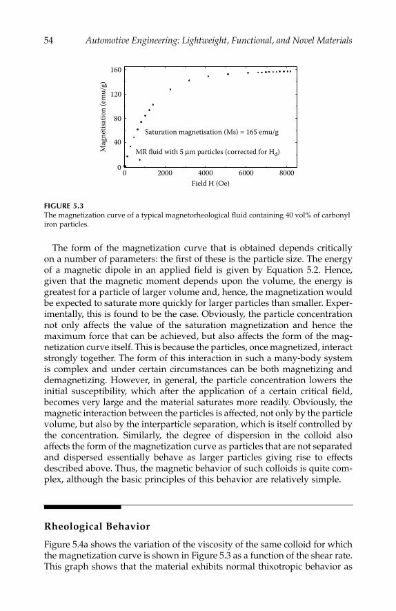
54
Automotive Engineering: Lightweight, Functional, and Novel Materials
The form of the magnetization curve that is obtained depends criticallyon a number of parameters: the first of these is the particle size. The energyof a magnetic dipole in an applied field is given by Equation 5.2. Hence,given that the magnetic moment depends upon the volume, the energy isgreatest for a particle of larger volume and, hence, the magnetization wouldbe expected to saturate more quickly for larger particles than smaller. Exper-imentally, this is found to be the case. Obviously, the particle concentrationnot only affects the value of the saturation magnetization and hence themaximum force that can be achieved, but also affects the form of the mag-netization curve itself. This is because the particles, once magnetized, interactstrongly together. The form of this interaction in such a many-body systemis complex and under certain circumstances can be both magnetizing anddemagnetizing. However, in general, the particle concentration lowers theinitial susceptibility, which after the application of a certain critical field,becomes very large and the material saturates more readily. Obviously, themagnetic interaction between the particles is affected, not only by the particlevolume, but also by the interparticle separation, which is itself controlled bythe concentration. Similarly, the degree of dispersion in the colloid alsoaffects the form of the magnetization curve as particles that are not separatedand dispersed essentially behave as larger particles giving rise to effectsdescribed above. Thus, the magnetic behavior of such colloids is quite com-plex, although the basic principles of this behavior are relatively simple.
Rheological Behavior
Figure 5.4a shows the variation of the viscosity of the same colloid for whichthe magnetization curve is shown in Figure 5.3 as a function of the shear rate.This graph shows that the material exhibits normal thixotropic behavior as
FIGURE 5.3
The magnetization curve of a typical magnetorheological fluid containing 40 vol% of carbonyl iron particles.
0
40
80
120
160
0 2000 4000 6000 8000
MR fluid with 5 μm particles (corrected for Hd)
Saturation magnetisation (Ms) = 165 emu/g
Field H (Oe)
Mag
netis
atio
n (e
mu/
g)
IP155_C005.fm Page 54 Monday, December 31, 2007 4:52 PM

Magnetorheological Fluids
55
expected with a slight hysteresis at low shear, again as expected. Figure 5.4bshows data for the same material under different values of applied magneticfield. Again, at low shear the thixotropic behavior of the fluid is significantlyenhanced by the presence of the magnetic field. For example, the low shearviscosity of the fluid in a field of 1.2 kOe is believed to be as high as 10
5
cP,whereas the zero shear viscosity in zero field is only of the order of 5000 cP.Of course, these values have to be extrapolated due to the fact that viscositycannot be measured in the absence of shear. Under higher shear conditions,it is clear that the effect of the magnetic field is less dramatic than it is atlow shear, but nonetheless for a shear rate of 1000 s
−
1
the change in theviscosity between zero field and 1.2 kOe is of the order of a factor 5.
Of course, for device application, the variation of shear stress with shearrate must also be examined. Ideally, one would wish for an almost linearrelationship, which cannot be achieved in a thixotropic fluid. The data inFigure 5.5 shows the variation of shear stress with shear rate for the same
FIGURE 5.4a
Viscosity versus shear rate for a typical magnetorheological fluid in zero-applied field.
FIGURE 5.4b
The effect of applied DC magnetic field on the viscosity of a typical magnetorheological fluid.
0
1000
2000
3000
4000
5000
0 200 400 600 800 1000
1st half of cycle: low to high shear2nd half of cycle: high to low shear
Viscosity cycle for TMR3 (50°C)
Shear rate s–1
Visc
osity
(cp)
0
20000
40000
60000
80000
0 250 500 750 1000 1250
H = 0H = 400 OeH = 800 OeH = 1200 Oe
Shear rate (s–1)
Visc
osity
(cP)
IP155_C005.fm Page 55 Monday, December 31, 2007 4:52 PM

56
Automotive Engineering: Lightweight, Functional, and Novel Materials
fluid as examined in the previous section and shows that an extended quasi-linear region does occur for shear rates between a few hundred s
−
1
up toaround 1300 s
−
1
, which is the limit of our measurement capability. Similarbehavior is observed for all values of field although the extent of the linearregion tends to decrease slightly as larger magnetic fields are applied. Giventhat the magnetic fields are maintaining a strong interaction between thecolloidal particles, this type of behavior is to be expected. However, the datashown in Figure 5.5 does indicate that a device with predictable propertiescould be made from such a fluid.
Electrorheological and Magnetorheological Devices
Early designs of devices that used electrorheological and magnetorheologicalfluids were generally very similar. Considering the simplest case of a smallpiston damper, the cylinder of the damper was filled with the appropriatefluid and a field, be it electric or magnetic, was applied in the region of thepiston. This is shown schematically in Figure 5.6 for the case of an magne-torheological damper where a small coil has been wound onto the piston toproduce a magnetic field between the piston itself and the mild steel body.The coil is energized simply by powering through the piston rod and, hence,the fluid lying between the piston and the casing is expected to exhibit themagnetorheological effect observed in the measurements on the bulk fluid.
The design of an electrorheological fluid device is essentially similar exceptthat a very high voltage must be generated between the piston and the casing,again supplied in some way through the piston rod. In the case of an elec-trorheological fluid, it is not possible to generate an electric field through thebulk of the liquid and, hence, only that small portion of the liquid lyingbetween the piston and the casing can be activated and take part in the
FIGURE 5.5
The variation of shear stress with shear rate for a typical magnetorheological fluid in a range of applied DC magnetic fields.
0
3000
6000
9000
0 500 1000 1500
H = 1200 Oe, τ0 = 5055 PaH = 800 Oe, τ0 = 2716 PaH = 400 Oe, τ0 = 1086 PaH = 0, τ0 = 411 Pa
Shear rate (s–1)
Shea
r str
ess (
Pa)
IP155_C005.fm Page 56 Monday, December 31, 2007 4:52 PM

Magnetorheological Fluids
57
electrorheological effect. However, for the case of magnetorheological fluids,this does not apply as it is relatively easy to generate a magnetic field in asignificantly larger volume, particularly when a highly permeable materialsuch as an magnetorheological fluid is present within that volume.
Hence, a revised design of an magnetorheological damper has been devel-oped by Liquids Research Ltd. using computer aided design (CAD) tech-niques to apply a magnetic field to the bulk of the fluid lying within thepiston cylinder. The fluid is then activated directly by the fixed coil and nopower is supplied to the piston itself. A photograph of the device, whoseperformance is discussed subsequently, is at Figure 5.7.
Evaluation of a Magnetorheological Damper
A full evaluation of this device has been undertaken using the facilities ofProdrive Ltd., who have extensive facilities for the testing of dampers. TheProdrive test rig is fitted with sensors to measure displacement and temper-ature. A power supply delivering a maximum voltage of 14 volts, with acurrent of up to 4 amps, is available to energize the coil. As will be obvious,these values are almost ideal for automotive application as opposed to the useof very high voltages which are necessary for electrorheological dampers.
The test rig is capable of delivering piston velocities of up to 3 m/s overa 200 mm stroke and can measure damper forces of up to 20 kN. The test
FIGURE 5.6
Schematic design of a traditional magnetorheological damper.
Mild steel piston
Mild steel
Nylon spacer PoleMild steelouter barrel
From coil topower
Piston rod
Gap for flux
Coil
IP155_C005.fm Page 57 Monday, December 31, 2007 4:52 PM
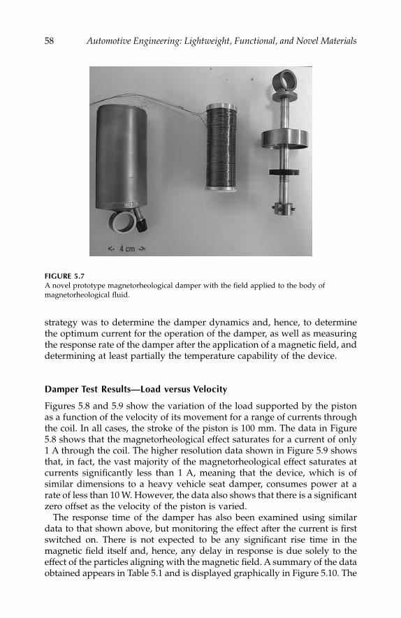
58
Automotive Engineering: Lightweight, Functional, and Novel Materials
strategy was to determine the damper dynamics and, hence, to determinethe optimum current for the operation of the damper, as well as measuringthe response rate of the damper after the application of a magnetic field, anddetermining at least partially the temperature capability of the device.
Damper Test Results—Load versus Velocity
Figures 5.8 and 5.9 show the variation of the load supported by the pistonas a function of the velocity of its movement for a range of currents throughthe coil. In all cases, the stroke of the piston is 100 mm. The data in Figure5.8 shows that the magnetorheological effect saturates for a current of only1 A through the coil. The higher resolution data shown in Figure 5.9 showsthat, in fact, the vast majority of the magnetorheological effect saturates atcurrents significantly less than 1 A, meaning that the device, which is ofsimilar dimensions to a heavy vehicle seat damper, consumes power at arate of less than 10 W. However, the data also shows that there is a significantzero offset as the velocity of the piston is varied.
The response time of the damper has also been examined using similardata to that shown above, but monitoring the effect after the current is firstswitched on. There is not expected to be any significant rise time in themagnetic field itself and, hence, any delay in response is due solely to theeffect of the particles aligning with the magnetic field. A summary of the dataobtained appears in Table 5.1 and is displayed graphically in Figure 5.10. The
FIGURE 5.7
A novel prototype magnetorheological damper with the field applied to the body of magnetorheological fluid.
IP155_C005.fm Page 58 Monday, December 31, 2007 4:52 PM

Magnetorheological Fluids
59
FIGURE 5.8
Variation of load with piston velocity for the damper shown in Figure 5.7 for a range of currents in the coil.
FIGURE 5.9
An expanded view of the data in Figure 5.8 showing the low-field behavior.
TABLE 5.1
Response Time of the Damper Shown in Figure 5.7 for a Range
of Applied DC Fields and Piston Velocities
Piston Velocity(mm/s) 1A 2A 3A 4A
100 76 ms 62 ms 44 ms 34 ms200 76 ms 60 ms 44 ms 40 ms300 50 ms 46 ms 34 ms 38 ms400 76 ms 56 ms 44 ms 40 ms500 86 ms 62 ms 38 ms 42 ms
–6
–2
2
6
–800 –400 0 400 800
0 A1 A2 A3 A4 A
Velocity (mm/s)
Load
(kN
)
–2.5
0
2.5
–250 250
1 A750 mA500 mA250 mA10 mA0 A
Piston velocity (mm/s)
Load
(kN
)
IP155_C005.fm Page 59 Monday, December 31, 2007 4:52 PM
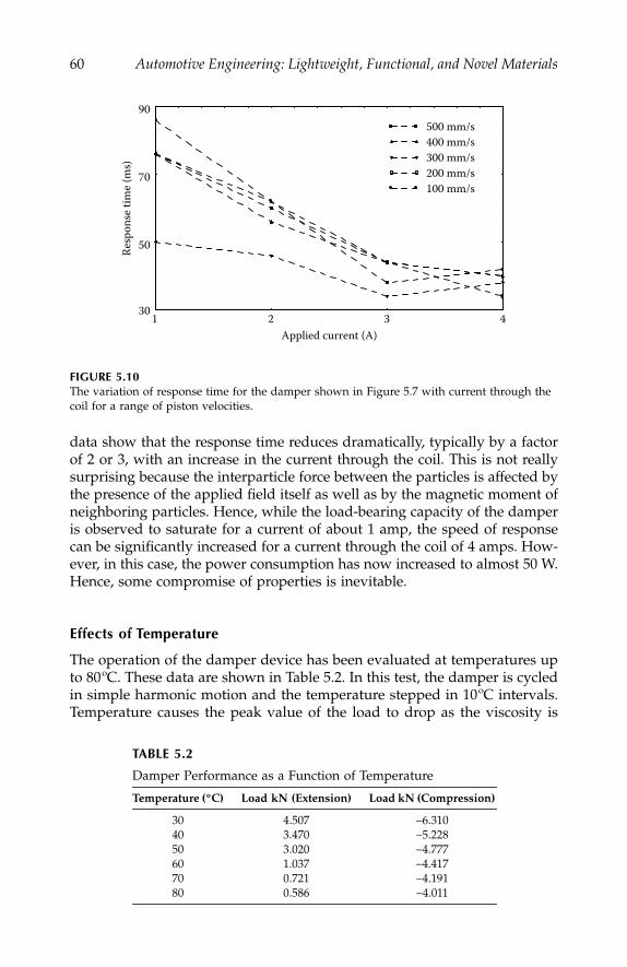
60
Automotive Engineering: Lightweight, Functional, and Novel Materials
data show that the response time reduces dramatically, typically by a factorof 2 or 3, with an increase in the current through the coil. This is not reallysurprising because the interparticle force between the particles is affected bythe presence of the applied field itself as well as by the magnetic moment ofneighboring particles. Hence, while the load-bearing capacity of the damperis observed to saturate for a current of about 1 amp, the speed of responsecan be significantly increased for a current through the coil of 4 amps. How-ever, in this case, the power consumption has now increased to almost 50 W.Hence, some compromise of properties is inevitable.
Effects of Temperature
The operation of the damper device has been evaluated at temperatures upto 80ºC. These data are shown in Table 5.2. In this test, the damper is cycledin simple harmonic motion and the temperature stepped in 10ºC intervals.Temperature causes the peak value of the load to drop as the viscosity is
FIGURE 5.10
The variation of response time for the damper shown in Figure 5.7 with current through the coil for a range of piston velocities.
TABLE 5.2
Damper Performance as a Function of Temperature
Temperature (ºC) Load kN (Extension) Load kN (Compression)
30 4.507
−
6.31040 3.470
−
5.22850 3.020
−
4.77760 1.037
−
4.41770 0.721
−
4.19180 0.586
−
4.011
30
50
70
90
1 2 3 4
500 mm/s400 mm/s300 mm/s200 mm/s100 mm/s
Applied current (A)
Resp
onse
tim
e (m
s)
IP155_C005.fm Page 60 Monday, December 31, 2007 4:52 PM
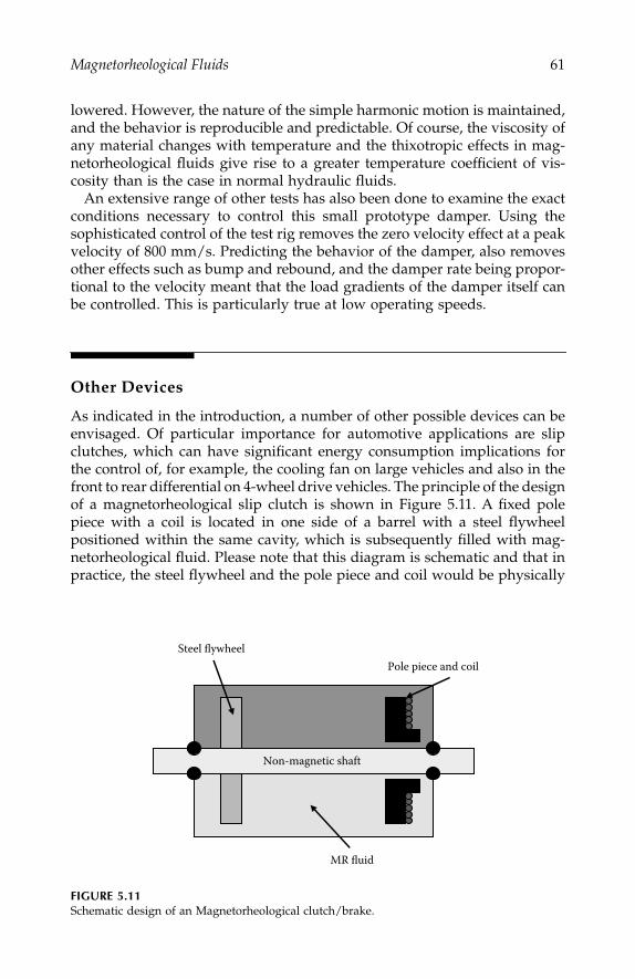
Magnetorheological Fluids
61
lowered. However, the nature of the simple harmonic motion is maintained,and the behavior is reproducible and predictable. Of course, the viscosity ofany material changes with temperature and the thixotropic effects in mag-netorheological fluids give rise to a greater temperature coefficient of vis-cosity than is the case in normal hydraulic fluids.
An extensive range of other tests has also been done to examine the exactconditions necessary to control this small prototype damper. Using thesophisticated control of the test rig removes the zero velocity effect at a peakvelocity of 800 mm/s. Predicting the behavior of the damper, also removesother effects such as bump and rebound, and the damper rate being propor-tional to the velocity meant that the load gradients of the damper itself canbe controlled. This is particularly true at low operating speeds.
Other Devices
As indicated in the introduction, a number of other possible devices can beenvisaged. Of particular importance for automotive applications are slipclutches, which can have significant energy consumption implications forthe control of, for example, the cooling fan on large vehicles and also in thefront to rear differential on 4-wheel drive vehicles. The principle of the designof a magnetorheological slip clutch is shown in Figure 5.11. A fixed polepiece with a coil is located in one side of a barrel with a steel flywheelpositioned within the same cavity, which is subsequently filled with mag-netorheological fluid. Please note that this diagram is schematic and that inpractice, the steel flywheel and the pole piece and coil would be physically
FIGURE 5.11
Schematic design of an Magnetorheological clutch/brake.
MR fluid
Non-magnetic shaft
Steel flywheel Pole piece and coil
IP155_C005.fm Page 61 Monday, December 31, 2007 4:52 PM
62
Automotive Engineering: Lightweight, Functional, and Novel Materials
much closer together. It should also be noted that such a device is alreadyavailable commercially from the Lord Corporation of Carey, North Carolina,and has found application in human exercise machines when operating asa brake.
When the coil is activated, the magnetorheological effect couples the fly-wheel to the fixed pole piece, thereby providing variable and extremely wellcontrolled coupling. Of course, such devices are subject to large centrifugaleffects at high speed and special design considerations must be applied inorder to limit these effects, which can destabilize the magnetorheologicalfluid. One example of a possible solution to this problem is the design oflabyrinthine plates within the slip clutch arrangements.
Summary
This chapter has described briefly, the historical development of magne-torheological and electrorheological fluids, which are now commerciallyavailable. The similarities and differences between these two classes of sim-ilar material have been highlighted and the properties of recently developedmagnetorheological fluids discussed. The fundamental mechanisms thatprovide the magnetorheological effect and can lead to the production ofmaterials with long term stability have been described together with boththe magnetic and rheological properties of such materials. A detailed eval-uation of a prototype magnetorheological damper, such as that used in theseat mountings of heavy vehicles, has been described together with a briefdescription of other possible devices for use in the automotive sector andelsewhere, such as slip clutches.
References
1. Winslow, W. M.,
J. Appl. Phys.
, Vol. 20, 1137–1240, 1949.2. Carlson, J. D., D. M. Catanzarite, and K. A. St. Clair, Lord Corporation, Cary,
NC 27511.3. Rabinov, J.,
AIEE Trans
., Vol. 67, 1308–1315, 1948.4. Weiss, K. D., T. G. Duclos, J. D. Carbon, M. J. Chrzan, and A. J. Margida, Soc.
Auto Engs., SAE paper 932451, 1998.5. See, for example, O’Handly, R. C., “Modern Magnetic Materials,” Wiley, Hoboken,
NJ, 2000.6. BASF Ag product “Carbonyl Iron SQ Grade.”
IP155_C005.fm Page 62 Monday, December 31, 2007 4:52 PM
63
6
Impact Loading
Nik Petrinic
CONTENTS
Introduction ...........................................................................................................63Adopted Methodology.........................................................................................65Research Focus ......................................................................................................67
Experimental Focus .....................................................................................67Numerical Focus ..........................................................................................67
Summary ................................................................................................................70References...............................................................................................................70
Introduction
During the past decade numerical crashworthiness simulation for vehicleand occupant safety protection has been greatly integrated into the vehicledesign process, and is now a mature technology. Manufacturers have con-siderably reduced costly and time-consuming prototype crash-testing pro-grams, and the physical testing is needed only to validate the design basedupon computer simulations. This has led to a reduction in development time(from 5 to 3 years on average) and a substantial cost saving (over 30%). Inaddition, the simulation-based design has led to consistently improved vehi-cle designs and a reduction in road deaths of over 30%.
Achieving reduction in fuel consumption and CO
2
emissions whileimproving vehicle performance and safety is a major challenge facing theautomotive industry today. Improvements in aerodynamics, fuel, motor, anddrive chain technology have provided an over 20% reduction in emissionsover the past ten years. However, these potential benefits have been negatedby a 20% increase in average vehicle weight during the same period.
IP155_C006.fm Page 63 Wednesday, January 2, 2008 12:24 PM

64
Automotive Engineering: Lightweight, Functional, and Novel Materials
The European Association of Automobile Manufacturers has a stated com-mitment to limit average output of CO
2
to 140 g/km per vehicle by the year2008 (currently 190 g/km).
1
If this objective is to be achieved, improvementsin all technological areas and, in particular, significant weight reductions, willbe essential. As a result, the industry is increasingly using high-strength metals(high-strength steels, aluminum, and magnesium [Figure 6.1]) and low-weightpolymers in order to achieve required weight reductions by compromisingneither performance nor occupant/pedestrian safety. It is realistic to expectlow-weight materials to reduce average vehicle weight by 15%
–
20%, which inturn will reduce fuel consumption by 0.5
–
1 Ltr/100 km. This is estimated toreduce considerably the total CO
2
emissions (by 30%) over the lifetime of the car.The present commercially available software for numerical simulation of
car crash events have proven remarkably reliable for designs based uponconventional ductile steels in which the principle response to impact loadingcomprises large inelastic material deformation and structural bending, buck-ling, and collapse of sectional members.
2
However, the algorithms employed
FIGURE 6.1
Examples of automotive components from high-strength, lightweight materials: (a) an axiallycrushed aluminum tube showing extensive metal tearing, (b) a magnesium door, and (c) a high-strength steel rear axle
.
A B
C
IP155_C006.fm Page 64 Wednesday, January 2, 2008 12:24 PM

Impact Loading
65
in such software are struggling to predict the dynamic material failure(including crack propagation) observed in experiments with newly utilizedhigh-strength steels or lightweight metallic and nonmetallic materials forautomotive applications.
3–6
These materials respond to dynamically appliedloading by illustrating considerably lower ductility when compared to con-ventional automotive steels, thus changing the principal structural responseto impact loading. Similar difficulties are encountered in predicting failurein jointing systems, which also play a significant role in crashworthy designs.
7
Consequently, present simulation results are not adequately predictive. As aresult, in order to avoid a return to costly prototype-based designs, it isimperative that failure modelling capabilities are improved if effective utili-zation of advanced materials is to be continued without compromising safety.
Adopted Methodology
In order to enable progress toward improved predictive modelling of defor-mation and failure of lightweight materials subjected to impact loading, thefollowing integrated experimental/numerical methodology has beenadopted by researchers in industry and academia interested in automotivecrashworthiness.
1. New experimental programs for selected advanced materials mustbe devised in order to provide required information on the depen-dency of material behavior to process history, temperature, and rateof loading. Such programs must encompass intelligent-selective test-ing rather than mass testing, and must provide manageable proce-dures and necessary data that enable determination of requiredconstitutive parameters. New methodologies must be established tocharacterize the deformation and failure of jointing systems.
2. New constitutive models that can include process history, tempera-ture effects, and can adequately describe the evolution of materialstate at required scale during loading, must be developed and imple-mented into existing software. Appropriate criteria for crack initia-tion and crack propagation (transition from continuum todiscontinuum) must be incorporated into constitutive models andnovel techniques, just as automatic remeshing around evolving dis-continuities must be used for improved accuracy. Extensive valida-tion against experimental data should be carried out duringdevelopment and implementation in order to ensure that mathemat-ical models adequately represent the observed physical behavior.
3. Inverse modelling techniques must be employed to fully quantifythe response of different materials to impact loading with respectto newly developed numerical algorithms, as not all constitutiveparameters will be directly measurable in experiments.
IP155_C006.fm Page 65 Wednesday, January 2, 2008 12:24 PM

66
Automotive Engineering: Lightweight, Functional, and Novel Materials
The development framework representing the basis of such design meth-odology can be described as an iterative process, part of which can be greatlyautomated by employing inverse modelling techniques based upon opti-mization and stochastic analysis. An example of such development frame-work for research into behavior of automotive materials subjected to impactloading is illustrated in Figure 6.2. In this approach, the investigation startswith small-scale laboratory experiments in order to provide both qualitativeand quantitative information on the observed behavior. The next step com-prises the theoretical (mathematical) abstraction of the selected phenomenaand is followed by development and implementation of numerical algo-rithms into chosen computational modelling framework. Direct comparisonbetween the results of experimental measurements and numerical simula-tions can be used to determine non-measurable modelling parameters, andcan also provide information on the accuracy of newly developed numericalmodelling tools.
Moreover, the inverse modelling for identification of nonmeasurable mod-elling parameters can establish the adequacy of newly developed algorithmsfor solving given problems. This follows from the ability of optimizationand stochastic methods to separate regions within analyzed parametricspaces if the employed models cannot adequately represent the observedbehavior.
FIGURE 6.2
Integrated experimental/numerical approach to predictive modelling of deformation andfailure of automotive materials.
Experimental
Numerical modelling
Data for numerical
Optimization
Experimental
Theoretical
Tolerance
Modify
Modify
Modify
IP155_C006.fm Page 66 Wednesday, January 2, 2008 12:24 PM
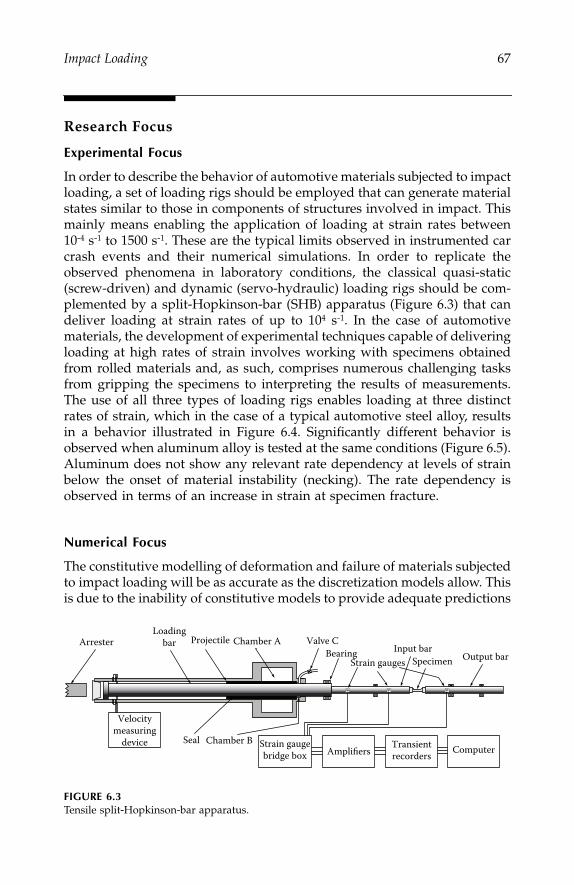
Impact Loading
67
Research Focus
Experimental Focus
In order to describe the behavior of automotive materials subjected to impactloading, a set of loading rigs should be employed that can generate materialstates similar to those in components of structures involved in impact. Thismainly means enabling the application of loading at strain rates between10
-
4
s
-
1
to 1500 s
-
1
. These are the typical limits observed in instrumented carcrash events and their numerical simulations. In order to replicate theobserved phenomena in laboratory conditions, the classical quasi-static(screw-driven) and dynamic (servo-hydraulic) loading rigs should be com-plemented by a split-Hopkinson-bar (SHB) apparatus (Figure 6.3) that candeliver loading at strain rates of up to 10
4
s
-
1
. In the case of automotivematerials, the development of experimental techniques capable of deliveringloading at high rates of strain involves working with specimens obtainedfrom rolled materials and, as such, comprises numerous challenging tasksfrom gripping the specimens to interpreting the results of measurements.The use of all three types of loading rigs enables loading at three distinctrates of strain, which in the case of a typical automotive steel alloy, resultsin a behavior illustrated in Figure 6.4. Significantly different behavior isobserved when aluminum alloy is tested at the same conditions (Figure 6.5).Aluminum does not show any relevant rate dependency at levels of strainbelow the onset of material instability (necking). The rate dependency isobserved in terms of an increase in strain at specimen fracture.
Numerical Focus
The constitutive modelling of deformation and failure of materials subjectedto impact loading will be as accurate as the discretization models allow. Thisis due to the inability of constitutive models to provide adequate predictions
FIGURE 6.3
Tensile split
-
Hopkinson-bar apparatus.
Strain gaugebridge box Amplifiers
Transientrecorders Computer
Velocitymeasuring
device
ArresterLoading
bar Chamber AProjectile Valve C
Seal
BearingStrain gauges Specimen
Chamber B
Output barInput bar
IP155_C006.fm Page 67 Wednesday, January 2, 2008 12:24 PM

68
Automotive Engineering: Lightweight, Functional, and Novel Materials
FIGURE 6.4
Rate dependency observed in typical automotive steel alloy.
FIGURE 6.5
Rate dependency observed in typical automotive aluminum alloy.
-100
0
100
200
300
400
500
600
700
20 40 60 80
Engineering strain (%)
Engi
neer
ing
stre
ss (M
Pa)
HighIntermediateQuasi-static
–20 0
0
50
100
150
200
250
300
0 5 10 15 20 25 30 35Engineering strain (%)
Engi
neer
ing
stre
ss (M
Pa)
T7 1e-4 6T7 1e-4 7T7 1e-4 8T7 100 2T7 100 3T7 100 4T7 600 1T7 600 2T7 600 3T7 1200 4T7 1200 5T7 1200 6
IP155_C006.fm Page 68 Wednesday, January 2, 2008 12:24 PM

Impact Loading
69
if forced to operate at representative volume element sizes considerablylarger than the scale at which the processes characterizing the observedphysical phenomena happen. For example, the required size of representa-tive volume element needed to adequately simulate linear elastic and mod-erate strain inelastic behavior of steel automotive components, may be ofthe order of 1
–
5 mm. On the other hand, if the modelling of localization andfailure is attempted in the same material, the size of representative volumeelement should be of the order of 0.05
–
0.1 mm. This poses high demandson the manufacturers to provide extreme computing power capable of large-scale crash simulations, as illustrated in Figure 6.6.
In addition, the large scale crash models will not predict accurately thematerial response unless the process history is taken into account in simu-lations. This means that a set of complex modelling operations is neededthat will enable mapping of the existing results following forming (stamping)simulations onto crash models. This way, the material states in structuralcomponents are taken into account, thus reflecting the variability in materialresponses depending on the process history.
The constitutive parameters for use in crash simulations can be obtainedfrom experiments on specimens obtained from virgin and processed materialsamples. Alternatively, the constitutive models used in simulations of form-ing processes should provide all required information needed by the consti-tutive models used in crash simulations.
The most critical aspect of numerical simulations of the behavior of light-weight automotive materials subjected to impact loading is the ability to
FIGURE 6.6
An example of large-scale crash simulation.
�ε = −1500 1s
�ε = −100 1s
�ε = − −10 4 1s
IP155_C006.fm Page 69 Wednesday, January 2, 2008 12:24 PM
70
Automotive Engineering: Lightweight, Functional, and Novel Materials
define the total energy absorption capabilities of employed materials. Thisis directly related to the failure in materials through cracking and fractureat which point the materials lose their capability to dissipate energy throughinelastic deformation. The ability to predict cracking and fracture in ductilelightweight materials represents the key to design for crashworthiness ofautomotive structures. In order to estimate accurately the total level of energyabsorption, the failure criteria (discrete and continuous) must fully satisfythe energy principles of thermodynamics in which the formulations of dis-sipation potentials must be fully validated against experiments. The devel-opment of failure criteria for both quasi-brittle, as well as ductile materialswithin the widely available finite element simulation software, is a challeng-ing research task satisfactory solution of which is not yet available. This ismainly due to the violation of the main assumption of the homogeneity ofdeformation within the representative volume element employed by thecontinuum mechanics and finite element method.
Summary
The behavior of selected automotive materials subjected to high-rate loadinghas been described in the context of computer-aided design for automotivecrashworthiness. The capabilities of currently used laboratory equipmentand numerical simulation tools have been outlined in order to provide anoverview of the design methodology presently employed. The focus isplaced on evaluating the response of the materials rather than the structureto impact loading in an attempt to quantify the capacity to dissipate kineticenergy during crash events.
At times when environmental issues play a dominant role in engineeringdesign, the consideration of lightweight materials represents one of the log-ical steps toward low fuel consumptions and reduced CO
2
emissions. How-ever, the introduction of lightweight materials requires rethinking of thecurrently employed design procedures, as the simple substitution of newmaterials into traditional structures does not automatically bring satisfactoryresults. Such a radical step is only possible if adequate experimental andcomputational supports are available, both of which also have to be modifiedand adapted during the redesign process.
References
1. CO
2
PERATE: The R&D programme on Automotive CO
2
Emissions reduction,Programme manager: Dr Ulf Palmer, 1999.
2. Scharnhorst, T., and Schettler-Köhler, R., “FEM-CRASH Experiences at VolkswagenResearch,”
Computational Mechanics
, 75–86, 1986.
IP155_C006.fm Page 70 Wednesday, January 2, 2008 12:24 PM

Impact Loading
71
3. Lemaitre, J., and Chaboche, J. L.,
Mechanics of Solid Materials
, CambridgeUniversity Press, Cambridge, UK, 1994.
4. Gurson, A. L., “Continuum theory of ductile rupture by void nucleation andgrowth, Part 1: Yield criteria and flow rules for porous media,”
J. Engng. Mates.Tech., ASME
, Vol. 99, 1977.5.
PAM-CRASH™ FE Code
, Engineering Systems International, 20 Rue Saarinen,Silic 270, 94578 Rungis-Cedex, France.
6. (
Strain rate testing of steels: German Automotive FAT group
), Fraunhofer Institut fuerangewandte Materialforschung (IFAM), Ermittlung dehnungsgeschwindigkeit-sabhaengiger Werkstoffkenngroessenan Karosserieblechen (Abschlussbericht zuFAT-Auftrag), 1993.
7. (
Spotweld testing: German Automotive FAT group
), Oeter, M., Aufbau und In-betriebnahme eines Hochgeschwindigkeits-material-und Bauteilpruefsystems,LWF Paderborn, 1999.
IP155_C006.fm Page 71 Wednesday, January 2, 2008 12:24 PM

IP155_C006.fm Page 72 Wednesday, January 2, 2008 12:24 PM
73
7
High-Temperature Electronic Materials
Colin Johnston
CONTENTS
Introduction ...........................................................................................................73Market Perspective ...............................................................................................75Module Technology..............................................................................................77Silicon Development ............................................................................................79Packaging and Interconnection Technology.....................................................81Assembly Process..................................................................................................82Reliability ...............................................................................................................83Summary ................................................................................................................84References...............................................................................................................85
Introduction
The modern automobile relies heavily on advanced electronic systems forvehicle performance and control, performing functions such as fuel injectionand emission control, anti-skid braking, active suspension, and electronictransmission control (see Figure 7.1). A recent study by the Freedonia groupestimates that the growth for automotive electronics alone will increase from$1,208 per vehicle in 1999 to $1,864 per vehicle in 2009.
1
While some of thisincrease is due to the evolution of telematic systems, most of this growthwill be due to hybrid vehicle electronics, collision avoidance and protectionsystems, electronic steering and vehicle stability, and powertrain manage-ment with the incorporation of new systems like drive-by-wire controlsystems (throttle, steer, brake, shift, and suspension by wire), collisionavoidance systems (automatic braking, steering, and throttling with radar),and advanced energy systems (42 volt, fuel cell controllers, and advancedenergy converters).
2
This accelerating trend toward more advanced electronics
IP155_C007.fm Page 73 Monday, December 31, 2007 4:53 PM

74
Automotive Engineering: Lightweight, Functional, and Novel Materials
will increase the use of vehicle electronics systems to an unprecedentedlevel.
3
This unprecedented technological growth in automotive electronics is bestillustrated by the evolution of one particular subsystem—powertrain man-agement. Engine and transmission management controllers now supportincreased feature content, with additional “smart” subsystems added toprovide detailed and fast electromechanical interfaces.
4–6
Modules like volt-age regulators, airflow meters, power switching, and smart solenoid switch-ing systems help the electronic control systems to monitor powertrainperformance and adjust mechanical operations.
This trend to smart sensing, processing, switching, and driving provides vehi-cle suppliers with two strategies for the overall systems electronics. One optionis to develop a very complex powertrain controller module capable of monitor-ing and adjusting a large number of inputs and outputs in real time. This optionis becoming increasingly difficult as systems require more feature content, whichin turn, increases module packaging size and increases vehicle wiring.
Another, more attractive option, is to create a number of smart powertrainmodules each performing a series of specific operations. Many companiesare now moving to these types of systems (called distributed controls), whichuse a series of “mechatronic modules” and smart actuators in conjunctionwith a smaller central controller unit. Such systems are integrated througha communications bus (e.g., CAN), giving more direct operational capabilityfor the controller system. Besides reducing the overhead of the local control
FIGURE 7.1
Electronic systems in a modern automobile.
Engine and power trainElectronic fuel injectionElectronic control unit (ECU)Transmission controlCruise controlCooling fans
Chassis and safetyActive 4-wheel steeringActive control suspensionAnti-lock braking (ABS)Traction controlVehicle stability control
Passenger comfortClimate controlPowered seat adjustmentElectric windowsDoor lock controlAir purifier
Signal comms and wiringMultiplexed communications systemStarter, alternator, battery monitoring
Displays and audioNavigation systemSound systemMobile telephoneTelevisionInternet access
IP155_C007.fm Page 74 Monday, December 31, 2007 4:53 PM
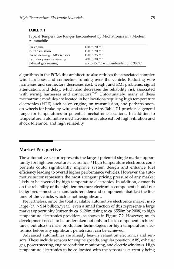
High-Temperature Electronic Materials
75
algorithms in the PCM, this architecture also reduces the associated complexwire harnesses and connectors running over the vehicle. Reducing wireharnesses and connectors decreases cost, weight and EMI problems, signalattenuation, and delay, which also decreases the reliability risk associatedwith wiring harnesses and connectors.
7–12
Unfortunately, many of thesemechatronic modules are located in hot locations requiring high temperatureelectronics (HTE) such as on-engine, on-transmission, and perhaps soon,on-wheels for brake-by-wire and steer-by-wire. Table 7.1 provides a generalrange for temperatures in potential mechatronic locations. In addition totemperature, automotive mechatronics must also exhibit high vibration andshock tolerance, and high reliability.
Market Perspective
The automotive sector represents the largest potential single market oppor-tunity for high temperature electronics.
13
High temperature electronics com-ponents could significantly improve system design and enhance fuelefficiency leading to overall higher performance vehicles. However, the auto-motive sector represents the most stringent pricing pressure of any marketlikely to be covered by high temperature electronics. In addition, demandson the reliability of the high temperature electronics component should notbe ignored—most car manufacturers demand components that last the life-time of the vehicle, which is not insignificant.
Nevertheless, since the total available automotive electronics market is solarge (ca. > $14 billion/year), even a small fraction of this represents a largemarket opportunity (currently ca. $120m rising to ca. $550m by 2008) to hightemperature electronics providers, as shown in Figure 7.2. However, muchdevelopment needs to be undertaken not only in basic component architec-tures, but also on mass production technologies for high temperature elec-tronics before any significant penetration can be achieved.
Advanced automobiles are already heavily reliant on electronics and sen-sors. These include sensors for engine speeds, angular position, ABS, exhaustgas, power steering, engine condition monitoring, and electric windows. Hightemperature electronics to be co-located with the sensors is currently being
TABLE 7.1
Typical Temperature Ranges Encountered by Mechatronics in a Modern
Automobile
On engine 150 to 200
°
CIn transmission 150 to 200
°
COn wheel—e.g., ABS sensors 150 to 250
°
CCylinder pressure sensing 200 to 300
°
CExhaust gas sensing up to 850
°
C with ambients up to 300
°
C
IP155_C007.fm Page 75 Monday, December 31, 2007 4:53 PM
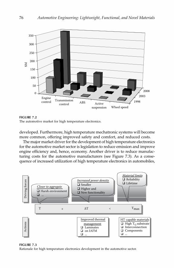
76
Automotive Engineering: Lightweight, Functional, and Novel Materials
developed. Furthermore, high temperature mechatronic systems will becomemore common, offering improved safety and comfort, and reduced costs.
The major market driver for the development of high temperature electronicsfor the automotive market sector is legislation to reduce emission and improveengine efficiency and, hence, economy. Another driver is to reduce manufac-turing costs for the automotive manufacturers (see Figure 7.3). As a conse-quence of increased utilization of high temperature electronics in automobiles,
FIGURE 7.2
The automotive market for high temperature electronics.
FIGURE 7.3
Rationale for high temperature electronics development in the automotive sector.
Enginecontrol Transmission
control ABS Activesuspension Wheel speed
19982003
20080
50
100
150
200
250
300
350
$MD
rivin
g fo
rces Increased power density
Material limitsReliabilityLifetime
Act
ions
HT capable materialsHigh TG substrateInterconnectionComponents...
Closer to aggregateHarsh environment...
SmallerHigher andNew functionality
managementLaminateson IAFM...
Improved t hermal
T + ΔT Tmax<
IP155_C007.fm Page 76 Monday, December 31, 2007 4:53 PM

High-Temperature Electronic Materials
77
there will be consumer benefits with improved reliability and increased effi-ciency that should work to reduce the average cost of ownership in terms ofboth reduced running costs and reduced maintenance requirements.
Module Technology
Currently, most harsh environment electronics are designed to withstand atemperature range of –40°C to +125°C. These systems must also typicallymeet automotive vibration requirements while exceeding 10 years and100,000 miles of operation. To limit the effects of the vehicle environment,electronics modules are often separated from the mechanical systems, whichthey control. Locations like vehicle firewalls (Figure 7.4) and fender wellsoffer the ability to sink module-generated heat while reducing exposure totemperatures created by the mechanical systems, and allowing some accessto airflow available under-the-hood.
Unfortunately for designers, future vehicle electronic modules will bephysically integrated with the mechanical systems they are intended tocontrol. This will eliminate many of the module separation opportunities,and will place the electronics directly in the thermal generation areas of themechanical systems and subject them to increased temperatures (Figure 7.5).
The next generation of automotive electronic control units (ECU) isexpected to be mounted close, or directly onto, the actuator—this means, forexample, directly at the engine, into transmission, or near the brake disk. Thislocalization of electronic control units represents the evolutionary step fromthe distributed mechanical system toward a functional integration ofmechanics and electric with electronics.
FIGURE 7.4
Electronic control on firewall.
IP155_C007.fm Page 77 Monday, December 31, 2007 4:53 PM

78
Automotive Engineering: Lightweight, Functional, and Novel Materials
For engine controllers, various reasons suggest having the electronic con-trol unit closely mechanically coupled with the engine itself (see Figure 7.6):lack of space in the engine compartment, reduction of wiring length andcomplexity, reduction of EMI/EMC related problems, improved intake aircooling action. The economical and logistical impact of treating the engineas self-standing component-ready, and fully tested and calibrated, for pro-duction at the end of the assembly line are also significant.
With respect to gasoline engines, the control of the intake/exhaustvalves, by means of sophisticated electronic systems, will be mandatoryfor further emissions reductions. Due to the large amount of electricalpower to be managed and the request for miniaturization, HT solutionsare under evaluation. In order to increase torque, performances and efficiencyof thermal engines, the functionalities of starter and generator/alternator(see Figure 7.7) are going to be integrated and realized within one electricalmachine (multifunctional starter and generator). Hence, various features willbe allowed, such as: start-up directly, start/stop, continuous power generation,
FIGURE 7.5
Typical under-hood temperatures.
FIGURE 7.6
Engine-mounted electronic control unit for diesel common rail application.
129 Ignition145 Alternatorsurface
Engine oil 145Transmission oil 145
Road surface 65
38 119 Exhaust system 527
Engine block 129
IP155_C007.fm Page 78 Monday, December 31, 2007 4:53 PM

High-Temperature Electronic Materials
79
energy recovery, and lowering idle-speed. The power electronic control unitrequired for the management of the machine will be installed in a positionthat optimizes losses and physical connections (wire harness).
The Train Control Unit (TCU) also represents an advanced mechatronicsystem for automatic gearbox control, directly mounted inside the gearbox,able to operate in harsh environments (Figure 7.8).
Silicon Development
Due to the strict low-cost requirements in the automotive industry, onlysilicon-based solutions seem to be promising for mass production targetingthe high-volume, cost-sensitive automotive market. From this point of view,
FIGURE 7.7
Multifunctional starter–generator system.
FIGURE 7.8
Mechatronic Train Control Unit.
Mechatronic TCU (prodmod)mounted inside gearbox
Ambient TemperatureTa < 110°C: 4000 h
110°C < Ta < 125°C: 1000 h125°C < Ta < 135°C: 100 × 1.0 h135°C < Ta < 140°C: 30 × 0.5 h
Ta up to 160°C for next generation Vibration
- Acceleration up to 30 g- Single shock: 100 g
Further Conditions- Limited mounting space- Resistance to ATF required (Automatic transmission fluid)
Mounting Location: Inside Gearbox
IP155_C007.fm Page 79 Monday, December 31, 2007 4:53 PM

80
Automotive Engineering: Lightweight, Functional, and Novel Materials
wide-bandgap semiconductors do not represent an affordable solution for theshort-medium term. However, with respect to silicon-based technology, sili-con-on-insulator (SOI) is rapidly growing and, as a consequence of this rapidgrowth, the cost of silicon-on-insulator devices is becoming more attractive.Some components in silicon-on-insulator are already available on the market(e.g., CAN controller) because of their robustness and immunity to noise, inaddition to the well-known behavior as a function of temperature. To reachthe demanding cost target in the automotive, standard designs and siliconCMOS bulk-technologies will be reused as much as possible, by high temper-ature hardening. As µCs, signal integrated units (logic, memory), ASICs andrelated driver integrated units are key components for the realization of con-trol units, the following activities will be performed by major silicon makers:
• Adaptation of CMOS technologies for the realization of 16/32 bit
m
C for T
j
≥
150°C• Process steps tuning and optimization of threshold voltage• Library optimization for high temperature (design, layout, specific
cell)• Evaluation and realization of test technologies/equipment for HT
applications• High temperature technology qualification• Evaluation and validation of high temperature bonding metallizations
The evolution of bare die (as well as packaged) components operating attemperatures well above 125°C° is described in Figure 7.9. The development
FIGURE 7.9
Evolution of packaged components versus bare die/FC as a function of temperature in theautomotive.
Dashboard/TelematicsAir bagGateway
Collision AvoidanceBraking(ABS/ASR/VSC/BbW)
ECU/TCUCooling vanPowersteering/Steer by wireECUEVT
TCU
–40/+85–40/+85–40/+85
–40/+125–40/+138–40/+140–40/+140–40/+150
–40/+150; 160
–40/+105–40/+115; 150
85 105 125 135 150 160Continuous max. temperature T(°C)
Passengercompartment
Modulecompartment
Under hood
On engine/Rack mounted
In transmission
Packaged componentsBare die/flip chip
Ta
IP155_C007.fm Page 80 Monday, December 31, 2007 4:53 PM
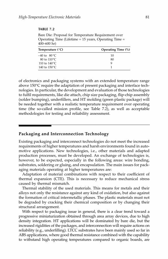
High-Temperature Electronic Materials
81
of electronics and packaging systems with an extended temperature rangeabove 150°C require the adaptation of present packaging and interface tech-nologies. In particular, the development and evaluation of those technologiesto fulfil requirements, like die attach, chip size packaging, flip-chip assembly(solder bumping), underfillers, and HT molding (green plastic package) willbe needed together with a realistic temperature requirement over operatingtime (the so-called mission profile, see Table 7.2), as well as acceptablemethodologies for testing and reliability assessment.
Packaging and Interconnection Technology
Existing packaging and interconnect technologies do not meet the increasedrequirements of higher temperatures and harsh environments found in auto-motive applications. New technologies, i.e., other materials and adaptedproduction processes, must be developed. An exchange of technologies is,however, to be expected, especially in the following areas: wire bonding,substrates, soldering or gluing, and encapsulation. The main issues for pack-aging materials operating at higher temperatures are:
Adaptation of material combinations with respect to their coefficient ofthermal expansion (CTE). This is necessary to reduce mechanical stresscaused by thermal mismatch.
Thermal stability of the used materials. This means for metals and theiralloys not only the resistance against any kind of oxidation, but also againstthe formation of critical intermetallic phases. The plastic materials must notbe degraded by cracking their chemical composition or by changing theirstructural arrangement.
With respect to packaging issue in general, there is a clear trend toward aprogressive miniaturization obtained through area array devices, due to highdensity integration. HT applications will be dominated by bare die, but theincreased rigidities of the packages, and interconnection will require actions onreliability (e.g., underfilling). LTCC substrates have been mainly used so far inABS applications, where good thermal resistance combined with the capabilityto withstand high operating temperatures compared to organic boards, are
TABLE 7.2
Bare Die: Proposal for Temperature Requirement over Operating Time (Lifetime
=
15 years, Operating Time
=
400–600 hr)
Temperature (
°
C) Operating Time (%)
–40 to 80 °C 1080 to 110°C 80
110 to 140°C 9140 to 150°C 1
IP155_C007.fm Page 81 Monday, December 31, 2007 4:53 PM
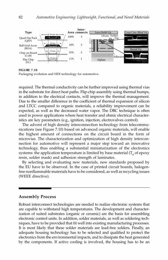
82
Automotive Engineering: Lightweight, Functional, and Novel Materials
required. The thermal conductivity can be further improved using thermal viasin the substrate for direct heat paths. Flip-chip assembly using thermal bumps,in addition to the electrical contacts, will improve the thermal management.Due to the smaller difference in the coefficient of thermal expansion of siliconand LTCC compared to organic materials, a reliability improvement can beexpected, as well as the decreased water vapor. The DBC technique is oftenused in power applications where heat transfer and ohmic electrical character-istics are key parameters (e.g., ignition, injection, electrovalves control).
The advent of high density interconnection technology from telecommu-nications (see Figure 7.10) based on advanced organic materials, will enablethe highest amount of connections on the circuit board in the form ofmicrovias. The characterization and optimization of high density intercon-nection for automotive will represent a major step toward an innovativetechnology, thus enabling a substantial miniaturization of the electronicssystems: the application temperature is limited by base material (T
g
of epoxyresin, solder mask) and adhesion strength of laminates.
By selecting and evaluating new materials, new standards proposed bythe EU have to be observed. In the case of printed circuit boards, halogen-free nonflammable materials have to be considered, as well as recycling issues(WEEE directive).
Assembly Process
Robust interconnect technologies are needed to realize electronic systems thatare capable to withstand high temperatures. The development and character-ization of suited substrates (organic or ceramic) are the basis for assemblingelectronic control units. In addition, solder materials, as well as soldering tech-niques, have to be provided that fit well into existing manufacturing processes.It is most likely that these solder materials are lead-free solders. Finally, anadequate housing technology has to be selected and qualified to protect theelectronics from the environmental impacts, and to dissipate the heat generatedby the components. If active cooling is involved, the housing has to be an
FIGURE 7.10
Packaging evolution and HDI technology for automotive.
Type AreaInter-
connects
Quad Flat Pack(QFP)
Ball Grid Array(BGA)
Chip-on Board(CoB)
Flip Chip(FC)
10 mm
15 mm
20 mm
30 mm100%
44%
25%
11%
2
3
3
1
123
45
Alplate
Layer Build-Up Cross Cuts: Blind Via
Buried Via
Adhesive
TopDrilled120 μm
IP155_C007.fm Page 82 Monday, December 31, 2007 4:53 PM

High-Temperature Electronic Materials
83
efficient interface to the cooler. Thermal simulation is needed to find out if therequirements of the specific application are met by packages, substrates, andinterconnect technology. Once the automotive electronic system has been con-ceived, several types of devices and packages must be assembled onto the samesubstrate. Hence, interconnect technologies will have to contact:
• Logic devices (high number of inputs and outputs and fine pitch)• Lower components (high currents, low impedance, back side
potential, heat removal)• Passive components (high mass leads to vibration and causes severe
mechanical stress)
Reliability
The required lifetimes for electronic components in automotive applicationsrange from typically 5000 hours for passenger cars to 20,000 hours for com-mercial vehicles. Specified failure probabilities for electronic control unitstypically vary between 100 and 500 out of 1 million in 10 years. Some typicalresults are shown in Table 7.1
FIGURE 7.11
Requested number of tested specimen hours to obtain a failure rate of 10 fit at 125°C.
Specimen Hours for Testing
0.0E+00
2.0E+07
4.0E+07
6.0E+07
8.0E+07
1.0E+08
1.2E+08
1.4E+08
1.6E+08
1.8E+08
2.0E+08
120 140 160 180 200 220Test temperature in °C
Spec
imen
hou
rs N
t a
Ea = 0,7 eVEa = 0,6 eVEa = 0,8 eV
IP155_C007.fm Page 83 Monday, December 31, 2007 4:53 PM
84
Automotive Engineering: Lightweight, Functional, and Novel Materials
In order to ensure a certain level of quality and reliability, defined stressconditions for the qualification testing of devices for automotive applica-tions have to be performed. These accelerated tests comprise electrical,environmental, and mechanical procedures like latch-up, electro-thermalinduced gate leakage, temperature cycles, autoclave, temperature-humiditybias, power temperature cycling, solderability, bond shear, vibration,mechanical shocks, etc. Developing related test standards requires theknowledge of the underlying failure mechanisms. Generally, these mecha-nisms are investigated by accelerated testing and, subsequently, accelerationfactors are calculated.
On entering the high temperature regime, further acceleration by simplyincreasing the temperature becomes a questionable approach. It is still uncer-tain whether such a methodology can be applied without changing thefailure mechanisms. In the future, new applications will run closer to thephysical limits of the devices and systems. This means that current qualifi-cation tests will no longer be sufficient for some applications. Since there isreduced safety margin for accelerated testing, new procedures for qualifica-tion must be developed. Ideally, these new qualification tests should alsoresult in an overall reduction in the qualification effort by, for example,employing simulation.
Summary
The automotive sector represents a critical driver for the wider scale adoptionof high temperature electronics. Even though the temperature range encoun-tered in automotive applications only extends the operating environment toa maximum of 150ºC for the active electronic components, there is still aconsiderable number of problems to overcome, including:
• Fundamental component performance• Component availability• Packaging• Reliability testing
Currently, most development is undertaken in disparate groups offeringbespoke solutions. However, a number of networks are being established totry to focus regional or national efforts, and one global network, HITEN,performs a critical integration role.
The future for high temperature electronics is inexorably tied to the auto-motive sector. However, it is clear that the majority of automotive applica-tions will be satisfied with incremental improvements to bulk silicontechnology, with development dominated by cost considerations.
IP155_C007.fm Page 84 Monday, December 31, 2007 4:53 PM

High-Temperature Electronic Materials
85
References
1. “World OEM Automotive Electronics to 2005,” Freedonia Group, Market Study,June 2001, www.freedoniagroup.com.
2. Kobe, Gerry, “What’s Driving the Growth,”
Automotive Industries
, Vol. 180,No. 8, August 2000.
3. Hansen, Paul, “Current Trends: What are the roadblocks facing mass market,high-tech electronic content?,”
Automotive Industries
, Vol. 181, No. 7, 26–29,July 2001.
4. Meyers, Bruce A., Jeff H. Burns, and Joseph M. Ratell, “Embedded Electronicsin Electro-Mechanical Systems for Automotive Applications,”
SAE International,Technical Paper
Series
, #2001-01-0691, March 5–8, 2001.5. “The Future of Automotive Electronics,”
Automotive Engineering International
,October 2000.
6. Constapel, R., J. Freytag, P. Hille, V. Lauer, and W. Wondrak, “High Tempera-ture Electronics for Automotive Applications,”
Int. Conf. on Integrated PowerSystems
(CIPS 2000), 20.-21.6.2000, Bremen, ETG Fachbericht 81, 46–52.7. Wondrak, W., A. Boos, and R. Constapel,
Design for Reliability in AutomotiveElectronics, Part I: Semiconductor Devices,
Microtec, Hannover, 25–27, 299–302,2000.
8. Lugert, G., E. Wirries, C. Beuther,
High Density-PCB Validation for AutomotiveApplications
, Electronic Forum, Waiblingen 2.-3.12., 1999 und Berlin: IEEE/CPMT 28-29.6.1999,
Advances in PCB and Substrate Technologies
.9. Lugert, G., T. Riepl, C. Beuther, E. Wirries
, Qualification of CSPs for AutomotiveEnvironment
, Flip Chip & Chip Scale Europe, Sindelfingen: Proceedings, March14–15, 2000.
10. Riepl, T., G. Lugert,
Interconnection Materials for Flip Chip Technology in HighTemperature Automotive Applications—A Comparative Study
, Micromat 2000, Ber-lin: Proceedings, 367–370, April 17–19, 2000.
11. Riepl, T., G. Lugert, R. Ingenbleek, W. Runge, L. Berchtold,
Integration ofMicromechanic Sensors, Actuators and Miniaturized High Temperature Electronicsin Advanced Transmission Systems
, Microtech 2000, Hannover: Proceedingspp. 599–604, September 25-27, 2000.
12. Lugert, G., S. Bolz, E. Wirries, T. Riepl,
Future Requirements and Technologies forAutomotive Control Units
, in preparation.13. Johnston, C.,
Markets for High Temperature Electronics
, HITEN, 2000.
IP155_C007.fm Page 85 Monday, December 31, 2007 4:53 PM

IP155_C007.fm Page 86 Monday, December 31, 2007 4:53 PM

87
8
Smart Materials
Clifford M. Friend
CONENTS
Smart Context........................................................................................................87Smart Technologies...............................................................................................88Technology Push or Application Pull?..............................................................90Smart Materials and the Automobile ................................................................91
Early Applications .......................................................................................91Well-Matched Applications........................................................................92Future ............................................................................................................93
Summary ................................................................................................................93
Smart Context
Smart technologies, which encompass both smart materials and smart struc-tures, are creating a sea change in engineering practice. Their fusion ofconventional structural materials with aspects of information technologyoffers the prospect of engineering systems that can sense their local environ-ment, interpret changes in this environment, and respond appropriately. Thisoffers the possibility of engineering structures that can operate at the verylimit of their performance envelopes and to their structural limits withoutfear of exceeding either; structures that can give maintenance engineers afull report on their performance history, as well as the location of defects,and structures that have the ability to counteract unwanted or potentiallydangerous conditions, and even in the future, effect self-repair.
Smart technologies are currently under serious development in a range ofsectors, including health and usage monitoring systems (HUMS) in aero-space and civil infrastructure, vibration control of buildings and pantographson trains, and noise reduction systems in turboprop aircraft. They have evenpenetrated the sporting goods market, with skis incorporating adaptive
IP155_C008.fm Page 87 Monday, December 31, 2007 4:54 PM
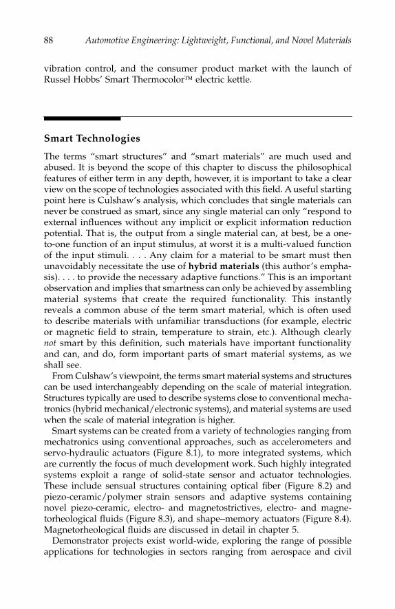
88
Automotive Engineering: Lightweight, Functional, and Novel Materials
vibration control, and the consumer product market with the launch ofRussel Hobbs’ Smart Thermocolor
™
electric kettle.
Smart Technologies
The terms “smart structures” and “smart materials” are much used andabused. It is beyond the scope of this chapter to discuss the philosophicalfeatures of either term in any depth, however, it is important to take a clearview on the scope of technologies associated with this field. A useful startingpoint here is Culshaw’s analysis, which concludes that single materials cannever be construed as smart, since any single material can only “respond toexternal influences without any implicit or explicit information reductionpotential. That is, the output from a single material can, at best, be a one-to-one function of an input stimulus, at worst it is a multi-valued functionof the input stimuli. . . . Any claim for a material to be smart must thenunavoidably necessitate the use of
hybrid materials
(this author’s empha-sis). . . . to provide the necessary adaptive functions.” This is an importantobservation and implies that smartness can only be achieved by assemblingmaterial systems that create the required functionality. This instantlyreveals a common abuse of the term smart material, which is often usedto describe materials with unfamiliar transductions (for example, electricor magnetic field to strain, temperature to strain, etc.). Although clearly
not
smart by this definition, such materials have important functionalityand can, and do, form important parts of smart material systems, as weshall see.
From Culshaw’s viewpoint, the terms smart material systems and structurescan be used interchangeably depending on the scale of material integration.Structures typically are used to describe systems close to conventional mecha-tronics (hybrid mechanical/electronic systems), and material systems are usedwhen the scale of material integration is higher.
Smart systems can be created from a variety of technologies ranging frommechatronics using conventional approaches, such as accelerometers andservo-hydraulic actuators (Figure 8.1), to more integrated systems, whichare currently the focus of much development work. Such highly integratedsystems exploit a range of solid-state sensor and actuator technologies.These include sensual structures containing optical fiber (Figure 8.2) andpiezo-ceramic/polymer strain sensors and adaptive systems containingnovel piezo-ceramic, electro- and magnetostrictives, electro- and magne-torheological fluids (Figure 8.3), and shape
–
memory actuators (Figure 8.4).Magnetorheological fluids are discussed in detail in chapter 5.
Demonstrator projects exist world-wide, exploring the range of possibleapplications for technologies in sectors ranging from aerospace and civil
IP155_C008.fm Page 88 Monday, December 31, 2007 4:54 PM
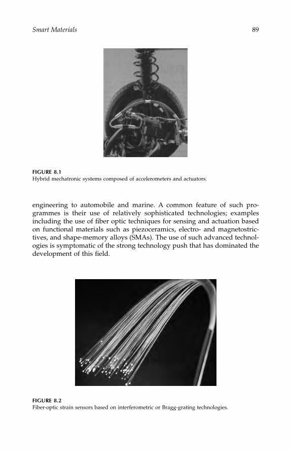
Smart Materials
89
engineering to automobile and marine. A common feature of such pro-grammes is their use of relatively sophisticated technologies; examplesincluding the use of fiber optic techniques for sensing and actuation basedon functional materials such as piezoceramics, electro- and magnetostric-tives, and shape-memory alloys (SMAs). The use of such advanced technol-ogies is symptomatic of the strong technology push that has dominated thedevelopment of this field.
FIGURE 8.1
Hybrid mechatronic systems composed of accelerometers and actuators.
FIGURE 8.2
Fiber-optic strain sensors based on interferometric or Bragg-grating technologies.
IP155_C008.fm Page 89 Monday, December 31, 2007 4:54 PM
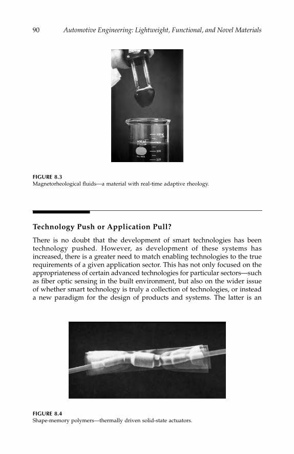
90
Automotive Engineering: Lightweight, Functional, and Novel Materials
Technology Push or Application Pull?
There is no doubt that the development of smart technologies has beentechnology pushed. However, as development of these systems hasincreased, there is a greater need to match enabling technologies to the truerequirements of a given application sector. This has not only focused on theappropriateness of certain advanced technologies for particular sectors—suchas fiber optic sensing in the built environment, but also on the wider issueof whether smart technology is truly a collection of technologies, or insteada new paradigm for the design of products and systems. The latter is an
FIGURE 8.3
Magnetorheological fluids—a material with real-time adaptive rheology.
FIGURE 8.4
Shape-memory polymers—thermally driven solid-state actuators.
IP155_C008.fm Page 90 Monday, December 31, 2007 4:54 PM
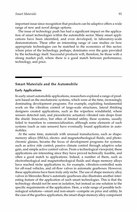
Smart Materials
91
important issue since recognition that products can be adaptive offers a widerange of new and novel design options.
The issue of technology push has had a significant impact on the applica-tion of smart technologies within the automobile sector. Many smart appli-cations have been identified, and even developed, in laboratory-scaledemonstrations. These offer an interesting range of case studies on howappropriate technologies can be matched to the economics of this sector;where price of the technology, perhaps, dominates over the gain providedby the technology itself. Successful products will, therefore, be those with astrong market pull, where there is a good match between performance,technology, and price.
Smart Materials and the Automobile
Early Applications
In early smart automobile applications, researchers explored a range of prod-ucts based on the mechatronic systems, which were at the time, increasinglydominating development programs. For example, exploiting fundamentalwork on the vibration control of large-scale structures, lateral thinkingdesigners created applications, such as the wiperless windshield, wheresensors detected rain, and piezoelectric actuators vibrated rain drops fromthe shield. Innovative, but often of limited utility, these systems, usuallyfailed to transition to commercialization, although some elements of suchsystems (such as rain sensors) have eventually found application in auto-mobiles.
At the same time, materials with unusual transductions, such as shape-memory alloys (SMAs), electro- and magnetorheological fluids, and photo-chromic glasses, became the focus of development programs for systems,such as active ride control, passive climate control through adaptive solargain, and simple active control valves. From a technological viewpoint, theseapplications are interesting since they have proved technically feasible, andoften a good match to applications. Indeed, a number of them, such aselectrorheological and magnetorheological fluids and shape memory alloyshave reached niche applications in, for example, vibration-controlled seatsfor off-road vehicles, and oil-flow valves in automatic gearboxes. However,these applications have been truly only niche. The use of shape memory alloyvalves in Mercedes Benz’s automatic gearboxes also illustrates another inter-esting feature of the application of such smart technologies. This is that thetechnology should not be seen in isolation, but instead as one solution to thespecific requirements of the application. Here, a wide range of possible tech-nological solutions—smart and non-smart—compete on price and utility. Inthe case of the gearbox application, the smart shape memory alloy component
IP155_C008.fm Page 91 Monday, December 31, 2007 4:54 PM
92
Automotive Engineering: Lightweight, Functional, and Novel Materials
finally saw only limited use in one generation of product, due to a competingmechatronic solution that has continued in service. This tells one that smarttechnologies will break through only where there is an appropriate matchbetween the application and technology, and where the smart solution hasa unique selling proposition. A number of such applications are now emerg-ing, and one can expect to see more as this new materials design approachdevelops further.
Well-Matched Applications
One well-matched automobile application is a return to vibration control,but no longer for unusual applications, such as windshields, but for activenoise control. Here, the smart structural concept of sensors embedded withinthe structure of the automobile and active excitation of components, such asthe roof panel, can be used to cancel noise within the passenger space. Thisis a mainstream smart-structural technology, transferred from developmentsin the turbo-prop aircraft sector, but appears to meet both the technologicaland commercial requirements of the automobile sector.
Perhaps more interesting has been the successful revisiting of technolo-gies, such as shape memory alloys as actuators to replace electromechanicalsystems in components, such as climate control, and as an alternative toelectrochromic rear-view mirrors. Both will shortly enter the market in Fiatcars where, through good matching between design and material selection,products such as shape memory alloy actuated electromechanical rear-viewmirrors can be manufactured as a low-cost, but highly effective alternativeto electrochromic technologies; doing to electrochromic materials what hasoften been done to shape memory alloys, i.e., producing a competing lowercost technological option for the same application.
Perhaps most interesting among these case studies is another Fiat conceptthat illustrates how the use of the smart adaptive design concept, selectionof smart materials, and their integration into automobile structures offerthe prospective of completely new automobile technologies of great signif-icance. An example is the active bonnet/hood. Most automobiles will havegreat difficulties in meeting pedestrian safety legislation, which will comeinto force in Europe in the near future. The smart bonnet is based on othermainstream smart applications, but is one well-matched to the automobilesector, producing a system arising from a real and significant applicationpull. One solution to the challenge of optimizing an automobile for every-day use, including good aerodynamics, and that is safer to pedestriansduring accidents, is to actively open the bonnet/hood during impact witha pedestrian. This alters the shape of the front of the automobile, minimizinginjury to the pedestrian. The active control of such a smart bonnet, thesensing of impacts, and its functioning only during pedestrian impact—tominimize both false-positive and negative responses, and the selection ofappropriate sensing technologies—such as piezoelectric polymers—is amajor challenge that has only just begun, but illustrates how automobile
IP155_C008.fm Page 92 Monday, December 31, 2007 4:54 PM
Smart Materials
93
performance, such as safety, could be improved in the future by the use ofsmart technologies.
Future
The automobile sector is only beginning to explore realistically the potentialof smart technologies. In many cases, such applications are substitutional,replacing more complex subsystems with simpler smart solutions. How-ever, it is clear from concepts, such as the smart bonnet/hood, that designsare already looking beyond substitutional applications to novel systems,where the required functionality is
only
deliverable through the smartroute. The impact of such step-change designs are often seen in purelyengineering terms, however, the use of smart design is also likely to extendbeyond the conventional engineering domain. For example, the penetrationof smart materials systems into the consumer goods market has alreadyopened new applications at the interface with industrial design. This areais of direct relevance to cockpit design within automobiles from both theergonomic and industrial design/styling viewpoints. Recent work on smartseats for aircraft also points to other interesting user-focused applications.The development of new smart automobile applications, therefore, appearsto be constrained only by the mind-set of engineering and industrialdesigners.
Many of the materials used to construct smart systems are already avail-able off-the-shelf but few of these functional materials have ever been devel-oped for smart engineering applications—many falling into the familiarcategory of “interesting materials looking for an application.” A future driverin this field will, therefore, be the optimization of such materials for integra-tion into smart products and, where necessary, their further development tomeet the particular performance requirements of different families of appli-cations. For example, in automobile applications, under-hood subsystemscould be considerably simplified by the use of solid-state actuators, such asshape memory alloys, if the operating temperatures of these alloys could beraised. So, not only is there a future challenge to engineering and industrialdesigners, but also to materials engineers and scientists, to ensure that theenabling materials technologies themselves are optimized to meet the strongmarket pull for smart automobile solutions.
Summary
Smart technologies are creating a sea change in engineering practice thatwill not leave the automobile sector unaffected. The fusion of conventionalstructural materials with aspects of control offers the prospect of a newdesign paradigm for automobile materials and structures. To exploit such
IP155_C008.fm Page 93 Monday, December 31, 2007 4:54 PM

94
Automotive Engineering: Lightweight, Functional, and Novel Materials
opportunities, we must avoid the attractions of pushing technologies, butinstead take a holistic design approach, responding to market pull by devel-oping smart technological solutions that best match the needs of the appli-cation on the basis of technology, cost, and the unique solutions offered bysmart technologies. Such effective matching of smart technologies to auto-mobile requirements will then offer new solutions in applications rangingfrom under-hood and passenger comfort subsystems, to smart noise andactive structural control.
IP155_C008.fm Page 94 Monday, December 31, 2007 4:54 PM

Section 3
Light Metals
Automotive engineering technology roadmaps from around the globe areunanimous in their call for new materials to allow for the reduction inautomotive weight. Reduced weight improves fuel efficiency and so cutsemissions. The challenge to ferrous materials by aluminium alloys in struc-tural applications and body panels has spurred the development of a newgeneration of commodity high-strength low alloy and other steels. Nonethe-less, the fraction of aluminium alloys in automobiles has continued to risesteadily, along with the increasing penetration of magnesium alloys in nicheapplications. This section considers the remaining challenges that must bemet if light alloys are to continue to find increasing use in automotivestructures, displacing ferrous-based materials, as well as the increasing com-petition from lightweight polymeric-based composites. Key areas for futuretechnological focus are identified as:
• Formability of aluminium and magnesium based alloys• Crashworthiness• Lightweight advanced materials (foams and cored materials)
IP155_S003.fm Page 1 Monday, December 10, 2007 4:15 PM

IP155_S003.fm Page 2 Monday, December 10, 2007 4:15 PM
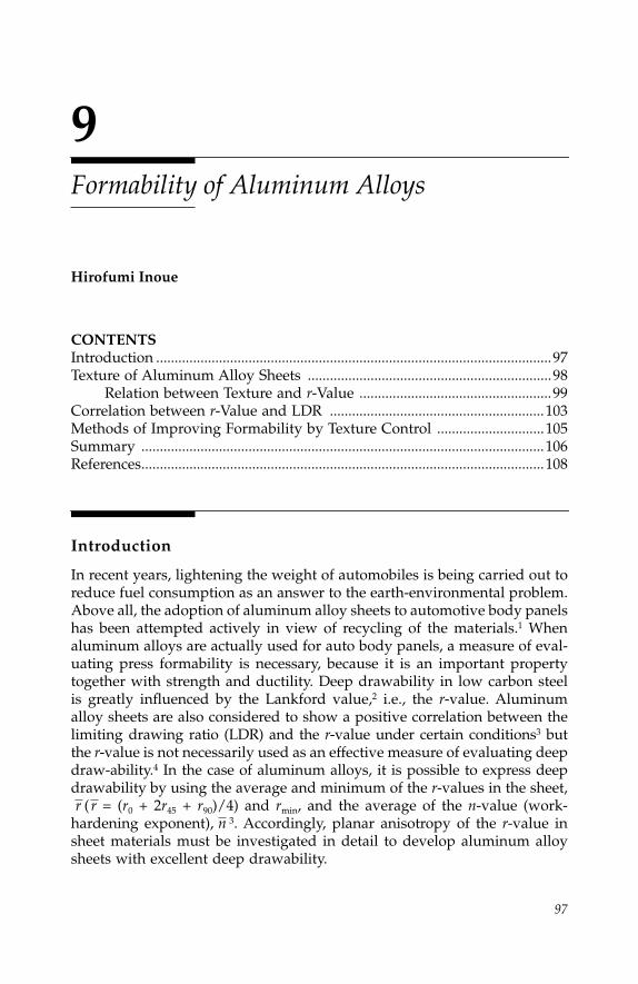
97
9
Formability of Aluminum Alloys
Hirofumi Inoue
CONTENTS
Introduction ...........................................................................................................97Texture of Aluminum Alloy Sheets ..................................................................98
Relation between Texture and
r
-Value ....................................................99Correlation between
r
-Value and LDR ..........................................................103Methods of Improving Formability by Texture Control .............................105Summary .............................................................................................................106References.............................................................................................................108
Introduction
In recent years, lightening the weight of automobiles is being carried out toreduce fuel consumption as an answer to the earth-environmental problem.Above all, the adoption of aluminum alloy sheets to automotive body panelshas been attempted actively in view of recycling of the materials.
1
Whenaluminum alloys are actually used for auto body panels, a measure of eval-uating press formability is necessary, because it is an important propertytogether with strength and ductility. Deep drawability in low carbon steelis greatly influenced by the Lankford value,
2
i.e., the
r
-value. Aluminumalloy sheets are also considered to show a positive correlation between thelimiting drawing ratio (LDR) and the
r
-value under certain conditions
3
butthe
r
-value is not necessarily used as an effective measure of evaluating deepdraw-ability.
4
In the case of aluminum alloys, it is possible to express deepdrawability by using the average and minimum of the
r
-values in the sheet,( = (
r
0
+
2
r
45
+
r
90
)/4) and
r
min
, and the average of the
n
-value (work-hardening exponent),
3
. Accordingly, planar anisotropy of the
r
-value insheet materials must be investigated in detail to develop aluminum alloysheets with excellent deep drawability.
r rn
IP155_C009.fm Page 97 Wednesday, January 2, 2008 2:13 PM

98
Automotive Engineering: Lightweight, Functional, and Novel Materials
Since the
r
-value is closely related to crystallographic orientation in polycrys-talline materials, it can be improved through texture control. However, inannealed aluminum alloy sheets produced by conventional processes, the aver-age
r
-value generally exhibits low values (less than 1.0), and it is in the rangeof 0.6 to 0.8 for 2xxx, 5xxx, and 6xxx series aluminum alloys for auto bodypanels, as shown in Table 9.1.
5
This is about half of the average
r
-value of lowcarbon steel. In order to find a possibility of improvement of the
r
-value, therelation between texture and the
r
-value must be exactly grasped by quantitativetexture analysis using crystallite orientation distribution function (ODF).
6
This chapter describes texture in aluminum alloy sheets, relations betweentexture and
r
-value, and the correlation between the
r
-value and the limitingdrawing ratio. In addition, methods for improving formability of aluminumalloy sheets are discussed in terms of texture control.
Texture of Aluminum Alloy Sheets
Aluminum alloys used as auto body panels are mainly 5xxx and 6xxx series,which have relatively excellent formability and corrosion resistance.
5
Thesealloy sheets are usually employed in an annealed (O) or solution heat-treated(T4) state after cold rolling. Since recrystallization occurs during the heattreatment, recrystallization texture is related to the
r
-value of the sheets.However, rolling texture that strongly affects the formation of recrystalliza-tion texture is also important in discussing optimum processing for texturecontrol. An example of recrystallization texture for 5052 and 6061 alloys
7
isshown in Figure 9.1. Both alloys before annealing had similar rolling texturesconsisting mainly of the
β
-fiber of {112}
<
111
>
(Cu-orientation) –
{
123
}
<
634
>
TABLE 9.1
Tensile Properties and Formability of Aluminium Alloys for Autobody Panels
with Sheet Gauge of 1 mm
5
Alloy and Temper
T. S. (MPa)
Y. S. (MPa)
Elongation (%)
n
-Value
r
-ValueOlsen Cup
Height (mm)
2002-T4 330 180 26 0.25 0.63 9.62036-T4 340 195 24 0.23 0.75 9.12037-T4 310 170 25 0.24 0.7 9.42038-T4 325 170 25 0.26 0.75 —
5182-O 275 130 26 0.33 0.8 9.95182-SSF 270 125 24 0.31 0.67 9.7
6009-T4 230 125 25 0.23 0.7 9.76010-T4 290 120 24 0.22 0.7 9.16111-T4 290 160 27 — — 8.46016-T4 235 125 28 0.26 0.7 —6022-T4 255 152 26 0.25 0.67 —
SPCC (steel) 315 175 42 0.23 1.39 11.9
IP155_C009.fm Page 98 Wednesday, January 2, 2008 2:13 PM

Formability of Aluminum Alloys
99
(S-orientation) – {011}
<
211
>
(Bs-orientation). Nevertheless, the recrystallizationtextures are significantly different in preferred orientations. A 5052 alloyshows cube texture of {001}
<
100
>
, while a 6061 alloy shows retained
β
-fiberand cube components. The retained
β
-fiber is composed of {123}
<
634
>
and{011}
<
211
>
orientations contained in rolling texture, and indicates higherorientation density than cube orientation. From the facts that softening byrecrystallization occurs more slowly in a 6061 alloy than in a 5052 alloy anda number of pancake-like grains exist in the recrystallized microstructure ofa 6061 alloy, it is speculated that fine particles present before annealing, andparticles precipitated during annealing, inhibit the migration of subgrainboundaries and recrystallized grain fronts, and consequently, continuousrecrystallization occurs in part. Fine precipitates thus play an important rolein the evolution of recrystallization texture.
Relation between Texture and
r
-Value
Prediction of the
r
-value from experimentally measured texture should beperformed to clarify the relation between texture and the
r
-value. Bunge
6,8
proposed a method for predicting the
r
-value from an orientation distribu-tion function in polycrystalline materials based on the Taylor theory
9
andcalculated planar anisotropy of the
r
-value for a low carbon steel sheet.
10
This method is applied to aluminum alloy sheets.
FIGURE 9.1
Orientation distribution functions of (a) 5052 and (b) 6061 aluminum alloy sheets cold rolledto 90% reduction and subsequently annealed for 3 ks at 573 and 623 K, respectively.
(a) (b)
11.7
11.7
11.7{001}⟨100⟩
{011}⟨211⟩{123}⟨634⟩{001}⟨100⟩
90°
90°
0°
φ
ϕ1 90°
90°
0°
φ
ϕ1
ϕ2 = 0°, 5°, ....., 90°, ϕ2 = 0°, 5°, ....., 90°Levels: 1, 2, 3, 4, 6, 8, 10 Levels: 1, 2, 3, 4
3.5
3.5
3.5
3.9
4.3
4.3
4.3
4.3
4.3
IP155_C009.fm Page 99 Wednesday, January 2, 2008 2:13 PM
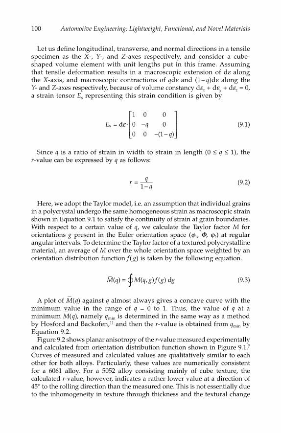
100
Automotive Engineering: Lightweight, Functional, and Novel Materials
Let us define longitudinal, transverse, and normal directions in a tensilespecimen as the
X
-,
Y
-, and
Z
-axes respectively, and consider a cube-shaped volume element with unit lengths put in this frame. Assumingthat tensile deformation results in a macroscopic extension of d
e
alongthe
X
-axis, and macroscopic contractions of
q
d
e
and (1–
q
)d
e
along the
Y
- and
Z
-axes respectively, because of volume constancy d
e
x
+ d
e
y
+ d
e
z
= 0,a strain tensor
E
s
representing this strain condition is given by
(9.1)
Since
q
is a ratio of strain in width to strain in length (0
≤
q
≤
1), the
r
-value can be expressed by
q
as follows:
(9.2)
Here, we adopt the Taylor model, i.e. an assumption that individual grainsin a polycrystal undergo the same homogeneous strain as macroscopic strainshown in Equation 9.1 to satisfy the continuity of strain at grain boundaries.With respect to a certain value of
q
, we calculate the Taylor factor
M
fororientations
g
present in the Euler orientation space (
j
1
,
F
,
j
2
) at regularangular intervals. To determine the Taylor factor of a textured polycrystallinematerial, an average of
M
over the whole orientation space weighted by anorientation distribution function
f
(
g
) is taken by the following equation.
(9.3)
A plot of against
q
almost always gives a concave curve with theminimum value in the range of
q
= 0 to 1. Thus, the value of
q
at aminimum , namely
q
min
is determined in the same way as a methodby Hosford and Backofen,
11
and then the
r
-value is obtained from
q
min
byEquation 9.2.
Figure 9.2 shows planar anisotropy of the
r
-value measured experimentallyand calculated from orientation distribution function shown in Figure 9.1.
7
Curves of measured and calculated values are qualitatively similar to eachother for both alloys. Particularly, these values are numerically consistentfor a 6061 alloy. For a 5052 alloy consisting mainly of cube texture, thecalculated
r
-value, however, indicates a rather lower value at a direction of45° to the rolling direction than the measured one. This is not essentially dueto the inhomogeneity in texture through thickness and the textural change
E q
qs d= ε ⋅ −
− −
⎡
⎣
⎢⎢⎢
⎤
⎦
⎥⎥⎥
1 0 00 00 0 1( )
rq
q=
1−
M q M q g f g g( ) ( , ) ( )= d�∫M q( )
M q( )
IP155_C009.fm Page 100 Wednesday, January 2, 2008 2:13 PM

Formability of Aluminum Alloys 101
during tensile deformation, but is probably due to the inadequacy of a modelused for calculation. Since locally inhomogeneous deformation tends to takeplace actually in Al-Mg alloys, such as a 5052 alloy, the conventional Taylormodel supposing homogeneous strain, namely the full constraints model(FC model)9 seems to be rather unsuitable for prediction of the r-value in a5052 alloy.
Therefore, it is necessary to calculate the r-value by the relaxed constraintsmodel (RC model)12 that relaxes some shear strains from a constrained statewith shear strain components of zero in Equation 9.1. The authors predictedthe r-values in ultra-low carbon steel sheets using the relaxed constraintsmodels with various relaxed shear components, and reported that the relax-ation of constraint in a shear strain component g23 perpendicular to the tensiledirection was necessary for exact estimation of the r-values.13 Here, thesubscripts 2 and 3 mean transverse and normal directions in a tensile spec-imen, respectively. In aluminum alloys as well as steel, the relaxed con-straints model on the g23 component has been employed to obtain betteragreement between measured and calculated values, provided that g23 is not setquite free, but |g23| is set between 0 and 0.5. Some results in annealed 5052 and6061 alloys are shown in Figure 9.3. For a 5052 alloy, the r-values calculatedby the relaxed constraints model are, on the whole, closer to the measuredr-values than those by the full constraints model, whereas for a 6061 alloythe r-values calculated by the full constraints model are closer to the mea-sured r-values. Thus, the r-values of 5xxx series Al-Mg alloys, which are ofthe solid solution strengthening type, may be successfully estimated by the
FIGURE 9.2Measured and calculated r-values for annealed 5052 and 6061 aluminum alloy sheets as afunction of angle to rolling direction.
0 15 30 45 60 75 90 0
0.1
0.25
0.50.7
1.0
1.52
4
10∞
0
0.1
0.2
0.3
0.4
0.5
0.6
0.7
0.8
0.9
1.0
Angle to rolling direction/deg.
5052 6061ExperimentalCalculated
r-va
lue
Stra
in ra
tio q
IP155_C009.fm Page 101 Wednesday, January 2, 2008 2:13 PM

102 Automotive Engineering: Lightweight, Functional, and Novel Materials
relaxed constraints model on shear strain g23 rather than the full constraintsmodel, because they tend to be deformed inhomogeneously.
In order to reveal what orientations are effective in improving the r-value,planar anisotropy of the r-value for various ideal orientations with Gaussiandistribution6 has been estimated using the full constraints model.7 Figure 9.4shows the calculated results for representative orientations observed inrolled and recrystallized aluminum alloy sheets. A {111} <110> orientationobserved occasionally in the surface region of a sheet possesses excellent r-values at any direction. It is, however, difficult to develop this orientationthrough sheet thickness. For cube orientation {001} <100>, the r-value is
FIGURE 9.3Comparisons between r-values calculated by the relaxed constraints (RC) and full constraints(FC) models for aluminum alloy sheets cold rolled to 90% reduction and annealed underdifferent conditions. (a) 5052 alloy annealed at 573 K for 500 s, (b) 5052 alloy annealed at 543 Kfor 1 ks, and (c) 6061 alloy annealed at 623 K for 500 s.
MeasuredRC modelFC model
MeasuredRC modelFC model
00
0.2
0.4
0.6
0.8
1.0
1.2
1.4
15 30 45 60 75 90Angle to rolling direction/deg.
00
0.20.40.60.81.01.21.41.61.82.02.22.42.6
15 30 45 60 75 90Angle to rolling direction/deg.
r-va
lue
r-va
lue
(a) (b)
MeasuredRC modelFC model
00
15 30 45 60 75 90Angle to rolling direction/deg.
0.20.40.60.81.01.21.41.61.82.0
r-va
lue
(c)
IP155_C009.fm Page 102 Wednesday, January 2, 2008 2:13 PM

Formability of Aluminum Alloys 103
approximately 1.0 at directions of 0° and 90°, but indicates fairly low valuesat other angles, especially zero at a direction of 45°. On the contrary, the r-value of R-orientation {123} <634> is about 4 in the range of 30° to 60°, andis not so low even at 0° and 90°. Bs- and Cu-orientations as well as R-orientation indicate fairly high r-values in the vicinity of 45°. From this figure,it is obvious that retained rolling texture components such as {123} <634>are effective for obtaining high r-values by realizable orientations.
Correlation between r-Value and Limiting Drawing Ration
The influence of the r-value and n-value on limiting drawing ratio (LDR)has been examined experimentally and theoretically3,14 limiting drawingration somewhat increases with increasing n-value when the -value isconstant. Since the n-value does not change so much for annealed aluminumalloys, there is slight influence of the n-value on limiting drawing ratio. Onthe other hand, limiting drawing ratio seems to increase with increasing -value for aluminum alloys. As described at the beginning, the -value ofusual aluminum alloys is in a narrow range from 0.5 to 1.0, so that it isdifficult to find a positive correlation between the -value and limiting
FIGURE 9.4Calculated r-values for typical ideal orientations with Gaussian distribution of f0 = 10° as afunction of angle to rolling direction.
00
0.1
0.2
0.3
0.4
0.5
0.6
0.7
0.8
0.9
1
15 30 45 60 75 900
0.11
0.25
0.43
0.67
1.00
1.50
2.33
4.00
9.00
r-va
lue
Stra
in ra
tio q
Angle to rolling direction/deg.
{001}<100>{011}<100>
{123}<634>{112}<111>
{011}<211>{111}<110>
∞
r
rr
r
IP155_C009.fm Page 103 Wednesday, January 2, 2008 2:13 PM
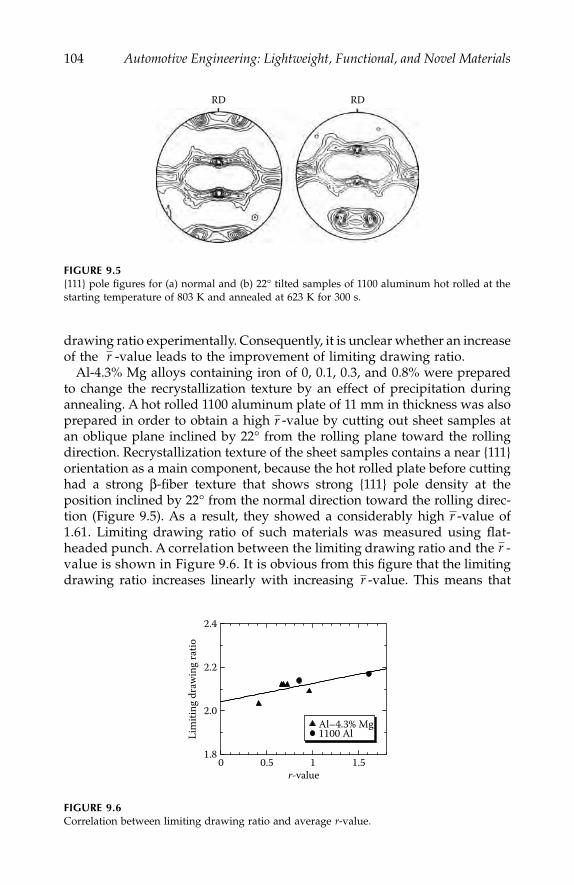
104 Automotive Engineering: Lightweight, Functional, and Novel Materials
drawing ratio experimentally. Consequently, it is unclear whether an increaseof the -value leads to the improvement of limiting drawing ratio.
Al-4.3% Mg alloys containing iron of 0, 0.1, 0.3, and 0.8% were preparedto change the recrystallization texture by an effect of precipitation duringannealing. A hot rolled 1100 aluminum plate of 11 mm in thickness was alsoprepared in order to obtain a high -value by cutting out sheet samples atan oblique plane inclined by 22° from the rolling plane toward the rollingdirection. Recrystallization texture of the sheet samples contains a near {111}orientation as a main component, because the hot rolled plate before cuttinghad a strong β-fiber texture that shows strong {111} pole density at theposition inclined by 22° from the normal direction toward the rolling direc-tion (Figure 9.5). As a result, they showed a considerably high -value of1.61. Limiting drawing ratio of such materials was measured using flat-headed punch. A correlation between the limiting drawing ratio and the -value is shown in Figure 9.6. It is obvious from this figure that the limitingdrawing ratio increases linearly with increasing -value. This means that
FIGURE 9.5{111} pole figures for (a) normal and (b) 22° tilted samples of 1100 aluminum hot rolled at thestarting temperature of 803 K and annealed at 623 K for 300 s.
FIGURE 9.6Correlation between limiting drawing ratio and average r-value.
RD RD
r
r
r
r
r
0 0.5 1 1.51.8
2.0
2.2
2.4
Lim
iting
dra
win
g ra
tio
r-value
Al–4.3% Mg1100 Al
IP155_C009.fm Page 104 Wednesday, January 2, 2008 2:13 PM

Formability of Aluminum Alloys 105
the improvement of deep drawability is possible in aluminum alloys if thetexture is adequately controlled.
Methods of Improving Formability by Texture Control
From the above section, it is found that increasing the -value by texturecontrol is effective in the improvement of formability. Here, guidelines oftexture control are discussed on the basis of relations between preferredorientation and the r-value shown in Figure 9.4. An important point oftexture control is what orientations should be developed preferentially fromvarious orientations reported actually in aluminum alloys.
There are two different guidelines to obtain a high -value. In analogywith steel, {111} <uvw> orientations such as {111} <110> and {111} <112> havehigh -values and small planar anisotropy, but it is difficult to develop theseorientations throughout thickness by conventional rolling and annealingprocesses. Recently, there are many studies on the formation of shear textureby warm rolling and differential speed rolling (asymmetric rolling). Sheartexture is attributable to additional shear deformation and consists mainlyof a <110>//RD fiber of {001} <110> – {112} <110> – {111} <110>. If {111} <110>can be developed after annealing, a high -value will be obtained. However,since the shear texture is weakened by annealing and the <110>//RD ori-entations other than {111} <110> also remain after annealing, the -value isnot so high as expected ( = ~1.0).15 It is necessary to retain a strong sheartexture including {111} <110> even after recrystallization. Another way toobtain a high -value is as follows. For raising the r-value at nearly alldirections in a sheet plane, R-orientation {123} <634> is considered to bemost effective from Figure 9.4, but this orientation shows a relatively lowr-value of about 0.7 at the 90° direction. Therefore, it is required that Gossorientation {011} <100>, which raises the r-value at the 90° direction, isdeveloped to some extent. Actually, Goss orientation has been observed insome examples.16 The selection of alloy compositions, annealing conditions,and so on causing moderate competition between precipitation and recrys-tallization, will be necessary to develop R-orientation as a main componentand Goss orientation as a secondary component. At least {001} <uv0>textures, such as cube orientation, are unfavorable for improving the r-value.
Warm rolling was actually carried out for the above Al–4.3% Mg alloys toobtain a high -value by the formation of shear texture including {111} <110>.Warm rolled sheets exhibited a sharp shear texture consisting of <110>//RDfiber components such as {001} <110>, {112} <110>, and {111} <110> in a rangefrom the surface to the quarter thickness, and a sharp β-fiber texture in arange from the quarter thickness to the central layer.17 The shear texture witha main component of {111} <110> remains after recrystallization annealing, as
r
r
r
r
rr
r
r
IP155_C009.fm Page 105 Wednesday, January 2, 2008 2:13 PM
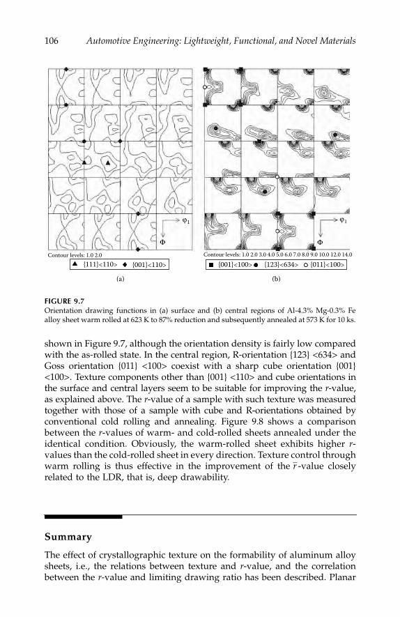
106 Automotive Engineering: Lightweight, Functional, and Novel Materials
shown in Figure 9.7, although the orientation density is fairly low comparedwith the as-rolled state. In the central region, R-orientation {123} <634> andGoss orientation {011} <100> coexist with a sharp cube orientation {001}<100>. Texture components other than {001} <110> and cube orientations inthe surface and central layers seem to be suitable for improving the r-value,as explained above. The r-value of a sample with such texture was measuredtogether with those of a sample with cube and R-orientations obtained byconventional cold rolling and annealing. Figure 9.8 shows a comparisonbetween the r-values of warm- and cold-rolled sheets annealed under theidentical condition. Obviously, the warm-rolled sheet exhibits higher r-values than the cold-rolled sheet in every direction. Texture control throughwarm rolling is thus effective in the improvement of the -value closelyrelated to the LDR, that is, deep drawability.
Summary
The effect of crystallographic texture on the formability of aluminum alloysheets, i.e., the relations between texture and r-value, and the correlationbetween the r-value and limiting drawing ratio has been described. Planar
FIGURE 9.7Orientation drawing functions in (a) surface and (b) central regions of Al-4.3% Mg-0.3% Fealloy sheet warm rolled at 623 K to 87% reduction and subsequently annealed at 573 K for 10 ks.
(a) (b)
Contour levels: 1.0 2.0 Contour levels: 1.0 2.0 3.0 4.0 5.0 6.0 7.0 8.0 9.0 10.0 12.0 14.0
ϕ1 ϕ1
Φ Φ
{111}<110> {001}<110> {001}<100> {123}<634> {011}<100>
r
IP155_C009.fm Page 106 Wednesday, January 2, 2008 2:13 PM
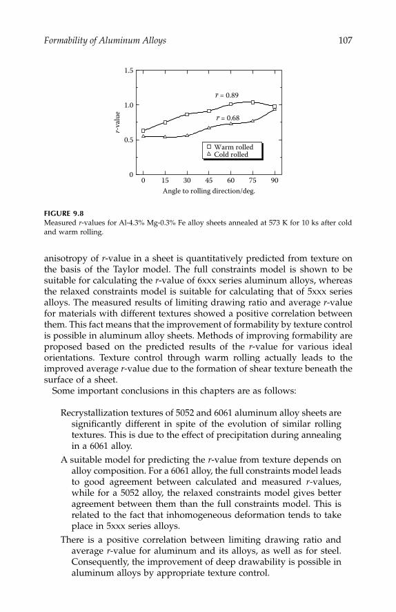
Formability of Aluminum Alloys 107
anisotropy of r-value in a sheet is quantitatively predicted from texture onthe basis of the Taylor model. The full constraints model is shown to besuitable for calculating the r-value of 6xxx series aluminum alloys, whereasthe relaxed constraints model is suitable for calculating that of 5xxx seriesalloys. The measured results of limiting drawing ratio and average r-valuefor materials with different textures showed a positive correlation betweenthem. This fact means that the improvement of formability by texture controlis possible in aluminum alloy sheets. Methods of improving formability areproposed based on the predicted results of the r-value for various idealorientations. Texture control through warm rolling actually leads to theimproved average r-value due to the formation of shear texture beneath thesurface of a sheet.
Some important conclusions in this chapters are as follows:
Recrystallization textures of 5052 and 6061 aluminum alloy sheets aresignificantly different in spite of the evolution of similar rollingtextures. This is due to the effect of precipitation during annealingin a 6061 alloy.
A suitable model for predicting the r-value from texture depends onalloy composition. For a 6061 alloy, the full constraints model leadsto good agreement between calculated and measured r-values,while for a 5052 alloy, the relaxed constraints model gives betteragreement between them than the full constraints model. This isrelated to the fact that inhomogeneous deformation tends to takeplace in 5xxx series alloys.
There is a positive correlation between limiting drawing ratio andaverage r-value for aluminum and its alloys, as well as for steel.Consequently, the improvement of deep drawability is possible inaluminum alloys by appropriate texture control.
FIGURE 9.8Measured r-values for Al-4.3% Mg-0.3% Fe alloy sheets annealed at 573 K for 10 ks after coldand warm rolling.
0 15 30 45 60 75 900
0.5
1.0
1.5
Angle to rolling direction/deg.
r-va
lue
Warm rolledCold rolled
r = 0.89
r = 0.68
IP155_C009.fm Page 107 Wednesday, January 2, 2008 2:13 PM
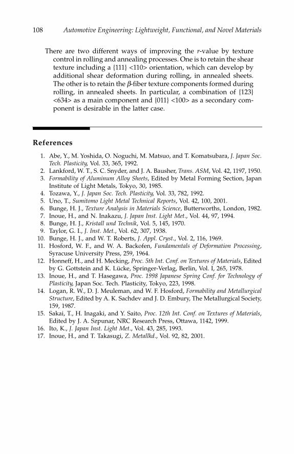
108 Automotive Engineering: Lightweight, Functional, and Novel Materials
There are two different ways of improving the r-value by texturecontrol in rolling and annealing processes. One is to retain the sheartexture including a {111} <110> orientation, which can develop byadditional shear deformation during rolling, in annealed sheets.The other is to retain the b-fiber texture components formed duringrolling, in annealed sheets. In particular, a combination of {123}<634> as a main component and {011} <100> as a secondary com-ponent is desirable in the latter case.
References
1. Abe, Y., M. Yoshida, O. Noguchi, M. Matsuo, and T. Komatsubara, J. Japan Soc.Tech. Plasticity, Vol. 33, 365, 1992.
2. Lankford, W. T., S. C. Snyder, and J. A. Bausher, Trans. ASM, Vol. 42, 1197, 1950.3. Formability of Aluminum Alloy Sheets, Edited by Metal Forming Section, Japan
Institute of Light Metals, Tokyo, 30, 1985.4. Tozawa, Y., J. Japan Soc. Tech. Plasticity, Vol. 33, 782, 1992.5. Uno, T., Sumitomo Light Metal Technical Reports, Vol. 42, 100, 2001.6. Bunge, H. J., Texture Analysis in Materials Science, Butterworths, London, 1982.7. Inoue, H., and N. Inakazu, J. Japan Inst. Light Met., Vol. 44, 97, 1994.8. Bunge, H. J., Kristall und Technik, Vol. 5, 145, 1970.9. Taylor, G. I., J. Inst. Met., Vol. 62, 307, 1938.
10. Bunge, H. J., and W. T. Roberts, J. Appl. Cryst., Vol. 2, 116, 1969.11. Hosford, W. F., and W. A. Backofen, Fundamentals of Deformation Processing,
Syracuse University Press, 259, 1964.12. Honneff, H., and H. Mecking, Proc. 5th Int. Conf. on Textures of Materials, Edited
by G. Gottstein and K. Lücke, Springer-Verlag, Berlin, Vol. I, 265, 1978.13. Inoue, H., and T. Hasegawa, Proc. 1998 Japanese Spring Conf. for Technology of
Plasticity, Japan Soc. Tech. Plasticity, Tokyo, 223, 1998.14. Logan, R. W., D. J. Meuleman, and W. F. Hosford, Formability and Metallurgical
Structure, Edited by A. K. Sachdev and J. D. Embury, The Metallurgical Society,159, 1987.
15. Sakai, T., H. Inagaki, and Y. Saito, Proc. 12th Int. Conf. on Textures of Materials,Edited by J. A. Szpunar, NRC Research Press, Ottawa, 1142, 1999.
16. Ito, K., J. Japan Inst. Light Met., Vol. 43, 285, 1993.17. Inoue, H., and T. Takasugi, Z. Metallkd., Vol. 92, 82, 2001.
IP155_C009.fm Page 108 Wednesday, January 2, 2008 2:13 PM

109
10
Ductile Magnesium
Toshiji Mukai and Kenji Higashi
CONTENTS
Introduction ........................................................................................................109Effect of Refining Grain Size ........................................................................... 110Effect of Texture ................................................................................................. 112Summary ............................................................................................................. 115References............................................................................................................. 115
Introduction
Recently, a number of magnesium alloys have been used as structural com-ponents, such as cases for portable electronic equipment due to their highspecific strength and good thermal conductivity. To reduce the weight ofautomobiles to reduce energy consumption, magnesium alloys are alsoexpected to be used in structural components. In order for magnesium to beused in structural components, it is necessary that it exhibits sufficientstrength and ductility under dynamic loading as well as static loading atambient temperature. Elongation-to-failure at a dynamic strain rate comparedto a static strain rate for some structural metals
1–3
are shown in Figure 10.1.Elongation-to-failure of magnesium at a dynamic strain rate is lower thanthat at a static strain rate
1
as well as other hexagonal close parted metals,such as zinc.
2
Therefore, the microstructure must be improved before mag-nesium can be used as a structural material. Wilson
4
demonstrated that theductility of pure magnesium could be enhanced by refining its grain size ata static strain rate. Mohri et al.
5
has also reported the ductility enhancementof an Mg-Y-RE (rare earth) alloy by hot extrusion. Mukai et al.
6
investigatedthe ductility enhancement for the same alloy under dynamic loading,stating that the enhancement of ductility was due to refinement of the
IP155_C010.fm Page 109 Monday, December 31, 2007 4:56 PM
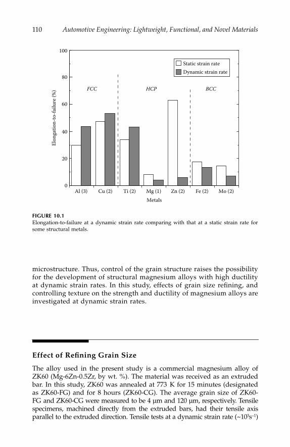
110
Automotive Engineering: Lightweight, Functional, and Novel Materials
microstructure. Thus, control of the grain structure raises the possibilityfor the development of structural magnesium alloys with high ductilityat dynamic strain rates. In this study, effects of grain size refining, andcontrolling texture on the strength and ductility of magnesium alloys areinvestigated at dynamic strain rates.
Effect of Refining Grain Size
The alloy used in the present study is a commercial magnesium alloy ofZK60 (Mg-6Zn-0.5Zr, by wt. %). The material was received as an extrudedbar. In this study, ZK60 was annealed at 773 K for 15 minutes (designatedas ZK60-FG) and for 8 hours (ZK60-CG). The average grain size of ZK60-FG and ZK60-CG were measured to be 4 µm and 120 µm, respectively. Tensilespecimens, machined directly from the extruded bars, had their tensile axisparallel to the extruded direction. Tensile tests at a dynamic strain rate (~10
3
s
−
1
)
FIGURE 10.1
Elongation-to-failure at a dynamic strain rate comparing with that at a static strain rate forsome structural metals.
Al (3) Cu (2) Ti (2) Mg (1) Zn (2) Fe (2) Mo (2)0
20
40
60
80
100
Metals
Elon
gatio
n-to
-failu
re (%
) FCC HCP BCC
Static strain rateDynamic strain rate
IP155_C010.fm Page 110 Monday, December 31, 2007 4:56 PM
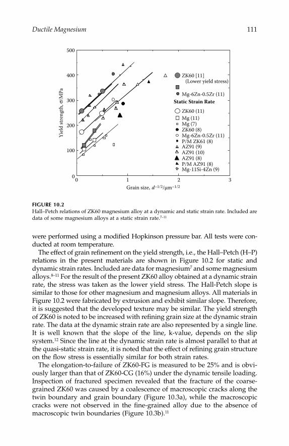
Ductile Magnesium
111
were performed using a modified Hopkinson pressure bar. All tests were con-ducted at room temperature.
The effect of grain refinement on the yield strength, i.e., the Hall–Petch (H–P)relations in the present materials are shown in Figure 10.2 for static anddynamic strain rates. Included are data for magnesium
7
and some magnesiumalloys.
8–11
For the result of the present ZK60 alloy obtained at a dynamic strainrate, the stress was taken as the lower yield stress. The Hall-Petch slope issimilar to those for other magnesium and magnesium alloys. All materials inFigure 10.2 were fabricated by extrusion and exhibit similar slope. Therefore,it is suggested that the developed texture may be similar. The yield strengthof ZK60 is noted to be increased with refining grain size at the dynamic strainrate. The data at the dynamic strain rate are also represented by a single line.It is well known that the slope of the line, k-value, depends on the slipsystem.
12
Since the line at the dynamic strain rate is almost parallel to that atthe quasi-static strain rate, it is noted that the effect of refining grain structureon the flow stress is essentially similar for both strain rates.
The elongation-to-failure of ZK60-FG is measured to be 25% and is obvi-ously larger than that of ZK60-CG (16%) under the dynamic tensile loading.Inspection of fractured specimen revealed that the fracture of the coarse-grained ZK60 was caused by a coalescence of macroscopic cracks along thetwin boundary and grain boundary (Figure 10.3a), while the macroscopiccracks were not observed in the fine-grained alloy due to the absence ofmacroscopic twin boundaries (Figure 10.3b).
11
FIGURE 10.2
Hall–Petch relations of ZK60 magnesium alloy at a dynamic and static strain rate. Included aredata of some magnesium alloys at a static strain rate.
7–11
Mg-6Zn-0.5Zr (11)
Mg (7)
AZ91 (8)P/M AZ91 (8)
32100
100
200
300
400
500
Mg-11Si-4Zn (9)
ZK60 (8)
P/M ZK61 (8)
ZK60 (11)
AZ91 (9)AZ91 (10)
Grain size, d–1/2/µm–1/2
Yiel
d st
reng
th, σ
/MPa
Mg (11)
Static Strain Rate
ZK60 [11] (Lower yield stress)
Mg-6Zn-0.5Zr (11)
IP155_C010.fm Page 111 Monday, December 31, 2007 4:56 PM
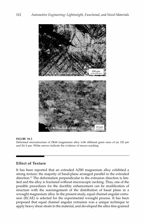
112
Automotive Engineering: Lightweight, Functional, and Novel Materials
Effect of Texture
It has been reported that an extruded AZ80 magnesium alloy exhibited astrong texture: the majority of basal-plane arranged parallel to the extrudeddirection.
13
The deformation perpendicular to the extrusion direction is lim-ited and the alloy is fractured without macroscopic necking. Thus, one of thepossible procedures for the ductility enhancement can be modification ofstructure with the rearrangement of the distribution of basal plane in awrought magnesium alloy. In the present study, equal channel angular extru-sion (ECAE) is selected for the experimental wrought process. It has beenproposed that equal channel angular extrusion was a unique technique toapply heavy shear strain to the material, and developed the ultra-fine-grained
FIGURE 10.3
Deformed microstructure of ZK60 magnesium alloy with different grain sizes of (a) 120 µmand (b) 4 µm. White arrows indicate the evidence of macro-cracking.
Tensile direction 10 µm
BB
100 µmTensile direction
A
IP155_C010.fm Page 112 Monday, December 31, 2007 4:56 PM
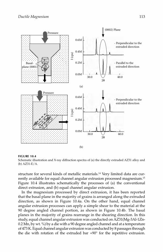
Ductile Magnesium
113
structure for several kinds of metallic materials.
14
Very limited data are cur-rently available for equal channel angular extrusion processed magnesium.
15
Figure 10.4 illustrates schematically the processes of (a) the conventionaldirect extrusion, and (b) equal channel angular extrusion.
In the magnesium processed by direct extrusion, it has been reportedthat the basal plane in the majority of grains is arranged along the extrudeddirection, as shown in Figure 10.4a. On the other hand, equal channelangular extrusion processes can apply a simple shear to the material at the90 degree angled channel portion, as shown in Figure 10.4b. The basalplanes in the majority of grains rearrange in the shearing direction. In thisstudy, equal channel angular extrusion was conducted on AZ31(Mg-3Al-1Zn-0.2 Mn, by wt. %) by a die with a 90 degree angled channel and at a temperatureof 473 K. Equal channel angular extrusion was conducted by 8 passages throughthe die with rotation of the extruded bar +90° for the repetitive extrusion.
FIGURE 10.4
Schematic illustration and X-ray diffraction spectra of (a) the directly extruded AZ31 alloy and(b) AZ31-E/A.
2θ
0.6M
0.4M
0.2M
0.0M30.0 40.0
- Perpendicular to the extruded direction
- Parallel to the extruded direction
(0002) Plane
Pressure
Pressure
0.6M
0.4M
0.2M
0.0M30.0 40.0
2θ
- Perpendicular to the extruded direction
(a)
(b)
Basal-plane (0001)
I (cp
s)I (
cps)
IP155_C010.fm Page 113 Monday, December 31, 2007 4:56 PM
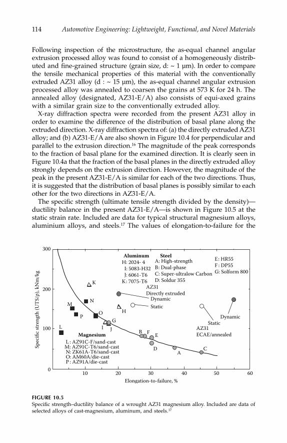
114
Automotive Engineering: Lightweight, Functional, and Novel Materials
Following inspection of the microstructure, the as-equal channel angularextrusion processed alloy was found to consist of a homogeneously distrib-uted and fine-grained structure (grain size, d: ~ 1 µm). In order to comparethe tensile mechanical properties of this material with the conventionallyextruded AZ31 alloy (d : ~ 15 µm), the as-equal channel angular extrusionprocessed alloy was annealed to coarsen the grains at 573 K for 24 h. Theannealed alloy (designated, AZ31-E/A) also consists of equi-axed grainswith a similar grain size to the conventionally extruded alloy.
X-ray diffraction spectra were recorded from the present AZ31 alloy inorder to examine the difference of the distribution of basal plane along theextruded direction. X-ray diffraction spectra of: (a) the directly extruded AZ31alloy; and (b) AZ31-E/A are also shown in Figure 10.4 for perpendicular andparallel to the extrusion direction.
16
The magnitude of the peak correspondsto the fraction of basal plane for the examined direction. It is clearly seen inFigure 10.4a that the fraction of the basal planes in the directly extruded alloystrongly depends on the extrusion direction. However, the magnitude of thepeak in the present AZ31-E/A is similar for each of the two directions. Thus,it is suggested that the distribution of basal planes is possibly similar to eachother for the two directions in AZ31-E/A.
The specific strength (ultimate tensile strength divided by the density)—ductility balance in the present AZ31-E/A—is shown in Figure 10.5 at thestatic strain rate. Included are data for typical structural magnesium alloys,aluminium alloys, and steels.
17
The values of elongation-to-failure for the
FIGURE 10.5
Specific strength–ductility balance of a wrought AZ31 magnesium alloy. Included are data ofselected alloys of cast-magnesium, aluminum, and steels.
17
A: High-strengthB: Dual-phaseC: Super-ultralow CarbonD: Soldur 355
403020100
100
200
300
Elongation-to-failure, %
Spec
ific s
tren
gth
(UTS
/ρ),
kNm
/kg
A
B
CD
EF
G
H
I J
K
L
M N
OP
H: 2024- 4 I: 5083-H32 J: 6061-T6K: 7075-T6
L : AZ91C-F/sand-castM: AZ91C-T6/sand-cast N: ZK61A-T6/sand-cast O: AM60A/die-cast P : AZ91A/die-cast
SteelAluminum
Magnesium
AZ31Directly extruded
AZ31ECAE/annealed
50 60
E: HR55F : DP55G: Solform 800
Dynamic Static
StaticDynamic
IP155_C010.fm Page 114 Monday, December 31, 2007 4:56 PM

Ductile Magnesium
115
magnesium alloys are markedly lower than those of structural steels. How-ever, AZ31-E/A exhibits a similar value of specific strength compared withthe cast magnesium alloys, and a larger value of elongation-to-failure thansteels. Tensile tests at a dynamic strain rate revealed that the texture con-trolled alloy exhibited a similar ductility under dynamic loading. Thus, it isnoted that the present alloy has a high possibility for structural use underdynamic loading.
Summary
Improvement of tensile mechanical properties under dynamic loadingwas demonstrated for commercial magnesium alloys. The yield stress of theZK60 alloy increased with refining grain-size at the dynamic strain rate witha similar Hall–Petch slope to that at a quasi-static strain rate. Enhancementof ductility can be also achieved by refining the grain structure for ZK60alloy. Simple shear was applied to a commercial AZ31 magnesium alloy byequal-channel-angular-extrusion for the development of a different texturecompared with the conventionally extruded alloy. X-ray diffraction spectraexamined for the parallel and perpendicular section to the extrusion direc-tion suggested that the fraction of basal plane was similar to each other forequal channel angular extrusion/annealed alloy, while it was obviouslydifferent for the conventionally extruded alloy. It was found from the tensiletest that the elongation-to-failure of the equal channel angular extrusion/annealed alloy exhibited ~ 50%, which was twice larger than that of theconventionally extruded alloy.
References
1. Mukai, T., et al.,
Light Weight Alloys for Aerospace Application III
, (TMS, Warrendale,483–488, 1995.
2. Kawata, K., et al.,
Proc. Symp.
HDP IUTAM, 313–317, 1968.3. Mukai, T., K. Higashi, and S. Tanimura,
Mater. Sci. Eng
., A176, 181–186, 1994.4. Wilson, D .V.,
J. Inst. Metals
, Vol. 98, 133–143, 1970.5. Mohri, T., et al.,
Mater. Sci. Eng
., A257, 287–294, 1998.6. Mukai, T., et al.,
Scripta Mater
., Vol. 39, 1249–1254, 1998.7. Chapman, J. A., and D. V. Wilson,
J. Inst. Metals
, Vol. 91, 39–40, 1962-63.8. Iwasaki, H., et al.,
J. Japan Soc. Powder and Powder Metall
., Vol. 11, 1350–1353,1996.
9. Mabuchi, M., K. Kubota, and K. Higashi,
Mater. Trans, JIM
, Vol. 36, 1249–1254,1995.
10. Nussbaum, G., et al.,
Scripta Metall
., Vol. 23, 1079–1084, 1989.
IP155_C010.fm Page 115 Monday, December 31, 2007 4:56 PM

116
Automotive Engineering: Lightweight, Functional, and Novel Materials
11. Mukai, T., et al.,
Mater. Trans
., Vol. 42, 1177–1181, 2001.12. Armstrong, R., I. Codd, R. M. Douthwaite, and N. J. Petch,
Phil. Mag
., Vol. 7,45–58, 1962.
13. Hilpert, M., et al.,
Magnesium Alloys and their Applications
, Werkstoff-informationsgesellshaft, Hamburg, 319–322, 1998.
14. Furukawa, M., Z. Horita, M. Nemoto, and T. G. Langdon,
J. Mater. Sci
., Vol. 36,2835–2843, 2001.
15. Mabuchi, M., K. Ameyama, H. Iwasaki, and K. Higashi,
Acta Mater
., Vol. 47,2024–2057, 1999.
16. Mukai, T., M. Yamanoi, H. Watanabe, and K. Higashi,
Scripta Mater
., Vol. 45,89–94, 2001.
17. Mukai, T., H. Watanabe, and K. Hiagshi,
Mater Sci. Tech
., Vol. 16, 1314–1319,2000.
IP155_C010.fm Page 116 Monday, December 31, 2007 4:56 PM

117
11
Enhancement of Crashworthiness
in Cellular Structures
T. Miyoshi, M. Itoh, T. Mukai, S. Nakano, and K. Higashi
CONTENTS
Introduction ......................................................................................................... 117Structure of Modified Foam.............................................................................. 118Compressive Behavior .......................................................................................120Energy Absorption..............................................................................................122Summary ..............................................................................................................123References.............................................................................................................123
Introduction
Recently, there has been great interest in using lightweight metallic foams(e.g., aluminium and magnesium) for automotive, railway, and aerospaceapplications where weight reduction and improved performance areneeded.
1
Metallic foams also have potential for absorbing impact energyduring vehicle crashes either against another vehicle or a pedestrian. Toeffectively absorb the impact energy, a material is required to exhibit anextended stress plateau. Thus, enhancement of the absorbed energy can beachieved by the extent of strain plateau and an increase in the plateau stress.The value of plateau stress can be increased by the selection of the matrixand its density. Thornton and Magee have demonstrated that the plateaustress of a closed-cell aluminum varied with composition and heat-treatmentof the matrix.
2
Hagen and Bleck have also reported that the plateau stresscould be increased with density using a commercially available closed-cellfoam, ALPORAS.
3
Gibson and Ashby
1
analyzed the relationship between the relative stress,
σ
p
1
/
σ
y5
,
and the relative density,
ρ
/
ρ
s
,
assuming that plastic collapse occurs
IP155_C011.fm Page 117 Monday, December 31, 2007 4:57 PM
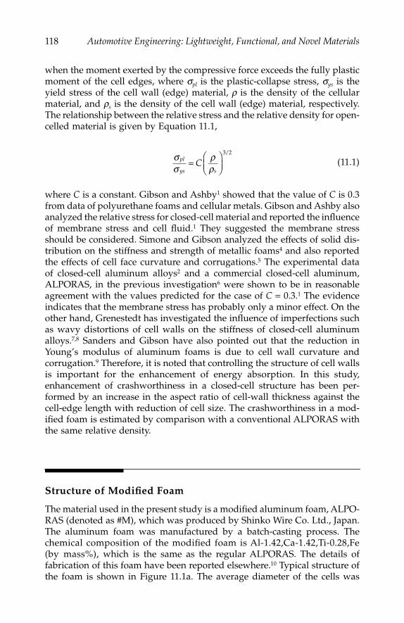
118
Automotive Engineering: Lightweight, Functional, and Novel Materials
when the moment exerted by the compressive force exceeds the fully plasticmoment of the cell edges, where
σ
pl
is the plastic-collapse stress,
σ
ys
is theyield stress of the cell wall (edge) material,
ρ
is the density of the cellularmaterial, and
ρ
s
is
the density of the cell wall (edge) material, respectively.The relationship between the relative stress and the relative density for open-celled material is given by Equation 11.1,
(11.1)
where
C
is a constant. Gibson and Ashby
1
showed that the value of
C
is 0.3from data of polyurethane foams and cellular metals. Gibson and Ashby alsoanalyzed the relative stress for closed-cell material and reported the influenceof membrane stress and cell fluid.
1
They suggested the membrane stressshould be considered. Simone and Gibson analyzed the effects of solid dis-tribution on the stiffness and strength of metallic foams
4
and also reportedthe effects of cell face curvature and corrugations.
5
The experimental dataof closed-cell aluminum alloys
2
and a commercial closed-cell aluminum,ALPORAS, in the previous investigation
6
were shown to be in reasonableagreement with the values predicted for the case of
C
=
0.3.
1
The evidenceindicates that the membrane stress has probably only a minor effect. On theother hand, Grenestedt has investigated the influence of imperfections suchas wavy distortions of cell walls on the stiffness of closed-cell aluminumalloys.
7,8
Sanders and Gibson have also pointed out that the reduction inYoung’s modulus of aluminum foams is due to cell wall curvature andcorrugation.
9
Therefore, it is noted that controlling the structure of cell wallsis important for the enhancement of energy absorption. In this study,enhancement of crashworthiness in a closed-cell structure has been per-formed by an increase in the aspect ratio of cell-wall thickness against thecell-edge length with reduction of cell size. The crashworthiness in a mod-ified foam is estimated by comparison with a conventional ALPORAS withthe same relative density.
Structure of Modified Foam
The material used in the present study is a modified aluminum foam, ALPO-RAS (denoted as #M), which was produced by Shinko Wire Co. Ltd., Japan.The aluminum foam was manufactured by a batch-casting process. Thechemical composition of the modified foam is Al-1.42,Ca-1.42,Ti-0.28,Fe(by mass%), which is the same as the regular ALPORAS. The details offabrication of this foam have been reported elsewhere.
10
Typical structure ofthe foam is shown in Figure 11.1a. The average diameter of the cells was
σσ
ρρ
pl
ys sC=
⎛⎝⎜
⎞⎠⎟
3 2/
IP155_C011.fm Page 118 Monday, December 31, 2007 4:57 PM
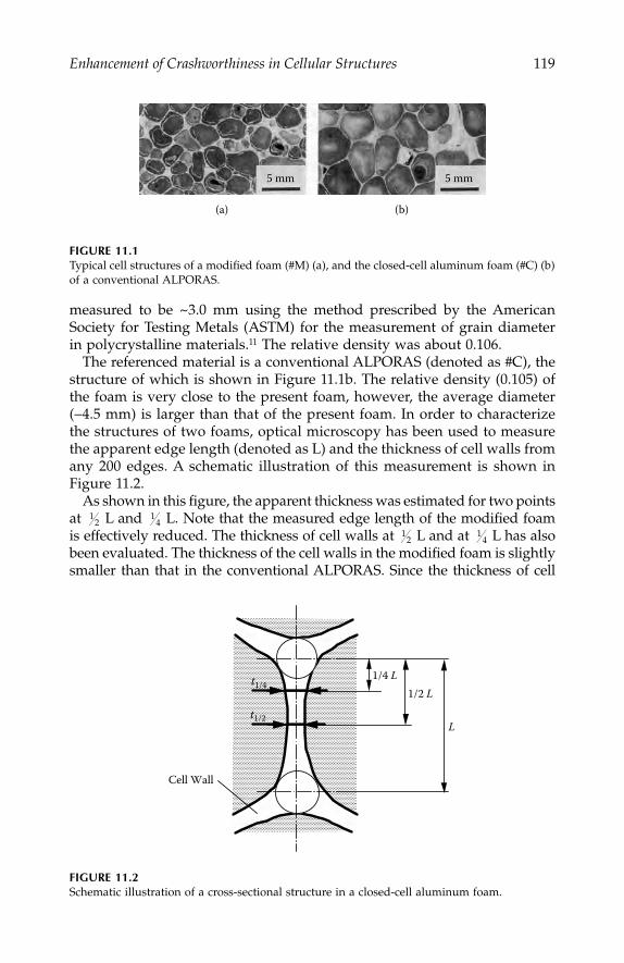
Enhancement of Crashworthiness in Cellular Structures
119
measured to be ~3.0 mm using the method prescribed by the AmericanSociety for Testing Metals (ASTM) for the measurement of grain diameterin polycrystalline materials.
11
The relative density was about 0.106.The referenced material is a conventional ALPORAS (denoted as #C), the
structure of which is shown in Figure 11.1b. The relative density (0.105) ofthe foam is very close to the present foam, however, the average diameter(
−
4.5 mm) is larger than that of the present foam. In order to characterizethe structures of two foams, optical microscopy has been used to measurethe apparent edge length (denoted as L) and the thickness of cell walls fromany 200 edges. A schematic illustration of this measurement is shown inFigure 11.2.
As shown in this figure, the apparent thickness was estimated for two pointsat L and L. Note that the measured edge length of the modified foamis effectively reduced. The thickness of cell walls at L and at L has alsobeen evaluated. The thickness of the cell walls in the modified foam is slightlysmaller than that in the conventional ALPORAS. Since the thickness of cell
FIGURE 11.1
Typical cell structures of a modified foam (#M) (a), and the closed-cell aluminum foam (#C) (b)of a conventional ALPORAS.
FIGURE 11.2
Schematic illustration of a cross-sectional structure in a closed-cell aluminum foam.
5 mm
(a) (b)
5 mm
12
14
12
14
L
1/2 L 1/4 L t1/4
t1/2
Cell Wall
IP155_C011.fm Page 119 Monday, December 31, 2007 4:57 PM

120
Automotive Engineering: Lightweight, Functional, and Novel Materials
walls at L is essentially greater than that at L for both foams, the cellwalls have a thickness gradient. However, the modified foam exhibits a moreuniform distribution of thickness compared with the conventional foam. Theaverage values of the measured edge length and wall thickness were summa-rized in Table 11.1. The aspect ratio of the wall thickness against the edgelength is also listed in Table 11.1. Note that the aspect ratio in the modifiedfoam is higher than that in a conventional ALPORAS on the average.
12
Compressive Behavior
Compressive tests were performed to evaluate the absorption energy. Spec-imens with dimensions of 16
×
11 mm were cut from each of the as-castaluminum foams. The compressive tests were carried out at a quasi-staticstrain rate of 1
×
10
3
s
−
1
on an Instron-type instrument, and at a quasi-dynamicstrain rate of 1
×
10
3
s
−
1
using the split-Hopkinson-pressure bar (SHPB)method for a number of specimens with a similar structure.
The curves of the five specimens were almost identical for both #M and#C. Typical stress–strain curves for the modified foam and a conventionalALPORAS at a quasi-static strain rate of 1
×
10
3
s
−
1
are shown in Figure 11.3.The diagram shows an elastic region at the initial stage, followed by a plateauregion (with nearly constant flow stress). After the plateau region, the flowstress rapidly increases because the specimen densifies. The stress–straincharacteristic for the closed-cell aluminum has already been reported.
13
Theplateau stress for each sample was evaluated as the flow stress at a nominalstrain of 0.2. The plateau stress of #M (denoted as
σ
Mp
) and #C (denoted as
σ
cp) are measured to 1.74 and 2.03 MPa, respectively. The relative density ofboth samples is identical. It is clearly observed that the plateau stress in themodified foam exhibits a higher value than that in a conventional ALPORAS.The increase in the plateau stress seems to be due to the increase in themembrane stress of cell walls with an aspect ratio of t
1/2
/L (see Table 11.1).
TABLE 11.1
The Measured Average Value of Edge Length and Wall Thickness
in a Modified Foam Comparing with a Conventional ALPORAS
Modified Foam(#M)
ConventionalALPORAS (#C)
Measured edge length (L) [mm] 1.91 2.68Measured thickness of cell wallAt 114 L (t
l/4
) [mm] 0.135 0.162At 112 L (t
1/2
) [mm] 0.112 0.132Aspect ratio [mm](t1l41L) 0.0693 0.0604(t1l41L) 0.0585 0.0505
12
14
IP155_C011.fm Page 120 Monday, December 31, 2007 4:57 PM
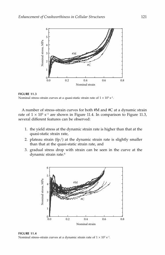
Enhancement of Crashworthiness in Cellular Structures
121
A number of stress–strain curves for both #M and #C at a dynamic strainrate of 1
×
10
3
s
−
1
are shown in Figure 11.4. In comparison to Figure 11.3,several different features can be observed:
1. the yield stress at the dynamic strain rate is higher than that at thequasi-static strain rate,
2. plateau strain (fp/) at the dynamic strain rate is slightly smallerthan that at the quasi-static strain rate, and
3. gradual stress drop with strain can be seen in the curve at thedynamic strain rate.
6
FIGURE 11.3
Nominal stress–strain curves at a quasi-static strain rate of 1
×
10
3
s
−
1
.
FIGURE 11.4
Nominal stress–strain curves at a dynamic strain rate of 1
×
10
3
s
−
1
.
0.80.60.40.20.00
1
2
3
4
5
6
Nominal strain
Nom
inal
stre
ss, M
Pa
#M
#C
0.80.60.40.20.00
1
2
3
4
5
6
Nominal strain
Nom
inal
stre
ss, M
Pa #M
#C
IP155_C011.fm Page 121 Monday, December 31, 2007 4:57 PM
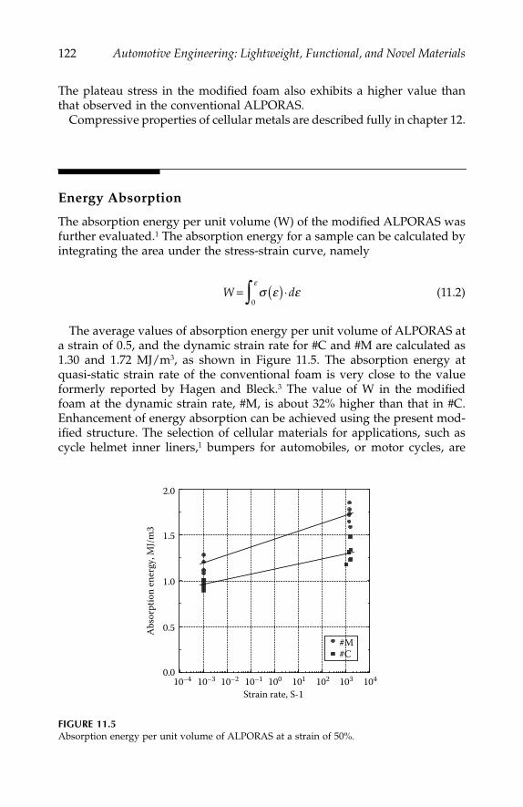
122
Automotive Engineering: Lightweight, Functional, and Novel Materials
The plateau stress in the modified foam also exhibits a higher value thanthat observed in the conventional ALPORAS.
Compressive properties of cellular metals are described fully in chapter 12.
Energy Absorption
The absorption energy per unit volume (W) of the modified ALPORAS wasfurther evaluated.
1
The absorption energy for a sample can be calculated byintegrating the area under the stress-strain curve, namely
(11.2)
The average values of absorption energy per unit volume of ALPORAS ata strain of 0.5, and the dynamic strain rate for #C and #M are calculated as1.30 and 1.72 MJ/m
3
, as shown in Figure 11.5. The absorption energy atquasi-static strain rate of the conventional foam is very close to the valueformerly reported by Hagen and Bleck.
3
The value of W in the modifiedfoam at the dynamic strain rate, #M, is about 32% higher than that in #C.Enhancement of energy absorption can be achieved using the present mod-ified structure. The selection of cellular materials for
applications, such ascycle helmet inner liners,
1
bumpers for
automobiles, or motor cycles, are
FIGURE 11.5
Absorption energy per unit volume of ALPORAS at a strain of 50%.
W d= ( ) ⋅∫ σ ε εε
0
10410310210110010–110–210–310–40.0
0.5
1.0
1.5
2.0
#M#C
Strain rate, S-1
Abs
orpt
ion
ener
gy, M
J/m3
IP155_C011.fm Page 122 Monday, December 31, 2007 4:57 PM
Enhancement of Crashworthiness in Cellular Structures
123
based on energy absorption characteristics. The results previously reportedfor
ALPORAS suggested that there was a large difference in mechanicalstrength and absorption energy obtained at a quasi-static and a dynamicstrain rate.
6
The examination at dynamic strain rate of the present foam isunderway. Optimization of cellular structures is important for
the enhance-ment of energy absorption in a closed-cell metallic foam.
Summary
Metallic foams have potential for absorbing impact energy. To effectivelyabsorb the impact energy, a material must exhibit an extended stress pla-teau. Thus, enhancement of the absorbed energy can be achieved by exten-sion of the strain plateau, and increasing the plateau stress. In this study,modification of the structure in a commercially available closed-cell alumi-num foam, ALPORAS, was performed. The edge length of this modifiedfoam is obviously reduced from that of a conventional ALPORAS, whilethe aspect ratio of the wall thickness to the edge length increases. From thecompressive tests at a quasi-static rate and a dynamic strain rate, the plateaustress of the modified foam was found to exhibit a marked increase com-pared to that of the conventional foam. The absorption energy per unitvolume (W) of the modified foam is 40% higher than that of a conventionalfoam.
References
1. Gibson, L. J., and M. P. Ashby, in
Cellular Solids, Structure and Properties—Secondedition
, Cambridge University Press, Cambridge, UK, 1997.2. Thornton, P. H., and C. L. Magee,
Metal!. Trans. A.,
Vol.
6A, 1253, 1975.3. Hagen, R. V., and W. Bleck,
Mat. Res. Soc. Symp. Proc
., ed. D. S. Schwartz,D. S. Shih, A. G. Evans, and H. N .G. Wadley, Materials Research Society, Vol.521, 59, 1998.
4. Simone, A. E., and L. J. Gibson,
Acta Mater.,
Vol. 46, 2139,
1998.5. Simone, A. E., and L. J. Gibson,
Acta Mater.,
Vol. 46, 3929,
1998.6. Mukai, T., H. Kanahashi, T. Miyoshi, M. Mabuchi, T. G. Nieh, and K. Higashi,
Scripta Mater.,
Vol. 40, 921,
1999.7. Grenestedt, J. L.,
J. Mech. Phys. Solids,
Vol. 46, 29,
1998.8. Grenestedt, J. L.,
Mat. Res. Soc. Symp. Proc
., ed. D. S. Schwartz, D. S. Shih,A. G. Evans, and H. N. G. Wadley, Materials Research Society, Vol. 521, 3, 1998.
9. Sanders, W., and L. Gibson,
Mat. Res. Soc. Symp. Proc
., ed. D. S. Schwartz,D. S. Shih, A. G. Evans, and H. N. G. Wadley, Materials Research Society, Vol. 521,53, 1998.
IP155_C011.fm Page 123 Monday, December 31, 2007 4:57 PM

124
Automotive Engineering: Lightweight, Functional, and Novel Materials
10. Miyoshi, T., M. Itoh, S. Akiyama, and A. Kitahara,
Mat. Res. Soc. Symp. Proc
.,ed. D. S. Schwartz, D. S. Shih, A. G. Evans, and H. N. G. Wadley, MaterialsResearch Society, Vol. 521, 133, 1998.
11. ASTM Designation E 112-82.12. Miyoshi, T., M. Itoh, T. Mukai, R. Kanahashi, H. Kohzu, S. Tanabe, and K. Higashi,
Scripta Mater.,
Vol.
41, 1055,
1999.13. Sugimura, Y., J. Meyer, M. Y. He, H. B. Smith, J. L. Grenstedt, and A. G. Evans,
Acta Mater.,
Vol. 45, 5245,
1997.
IP155_C011.fm Page 124 Monday, December 31, 2007 4:57 PM
125
12
Compressive Properties of Cellular Metals
Mamoru Mabuchi
CONTENTS
Introduction .........................................................................................................125Effect of the Solid Material ...............................................................................126Effect of the Cell Structure ................................................................................129Summary ..............................................................................................................131References.............................................................................................................131
Introduction
Recently, there has been a considerable increase in interest in cellular metals.Cellular metals are super-light metals exhibiting unique properties, such ashigh energy absorption.
1
Applications of cellular metals are wide ranging,e.g., impact energy absorbers, silencers, flame arresters, heaters, heatexchangers, constructional materials, etc.
Typical cellular metals are shown in Figure 12.1. Cellular solids are dividedinto two types; one is a closed-cellular solid where each cell is sealed offfrom its neighbor (Figure 12.1a), the other is an open-cellular solid whosecells connect through open faces (Figure 12.1b).
To date, the mechanical properties of cellular metals have been extensivelyinvestigated.
1
In general, a cellular metal shows an elastic region in the initialstage of applied strain, and then a plateau region with a nearly constant flowstress (collapse stress), and finally, a densification region where the flow stresssignificantly increases when the cellular metal is compressed. The collapsestress in the plateau region is strongly affected by the density of the material.Gibson and Ashby
1
analyzed the collapse stress of an open-cellular metal usingbending of struts, showing that the collapse stress of an open-cellular metal isproportional to the 3/2 power of the density. A closed-cellular metal alsoexhibits almost the same behavior as an open-cellular metal. However, the
IP155_C012.fm Page 125 Friday, January 4, 2008 6:44 PM

126
Automotive Engineering: Lightweight, Functional, and Novel Materials
collapse stress in the plateau region is considered to be affected not only bythe density, but also by the solid material and the cell structure. In this chapter,effects of the solid materials and the cell structure on compressive propertiesof a cellular metal are investigated.
Effect of the Solid Material
Compressive properties of the cellular SG91A aluminum alloy and cellularAZ91 magnesium alloy with the open-cell structure were investigated,
2
whereboth cellular alloys had the same cell structure. The nominal stress-nominalstrain curves are shown in Figure 12.2 for the cellular aluminium alloy, and inFigure 12.3 for the cellular magnesium alloy—five specimens of each material
FIGURE 12.1
Cellular metals, (A) closed-cell and (B) open-cell.
FIGURE 12.2
The nominal stress–nominal strain curves for the cellular SG91A Al alloy.
A B
6.4 mm 1 mm
1.5
1.0
SG91A AlRelative Density
(1)
(4)(3)
(5)
(2)
(1) : 0.0653(2) : 0.0446(3) : 0.0580(4) : 0.0471(5) : 0.0573
0.5
0.00 20 40
Nominal strain %
Nom
inal
stre
ss, M
Pa
60
IP155_C012.fm Page 126 Friday, January 4, 2008 6:44 PM
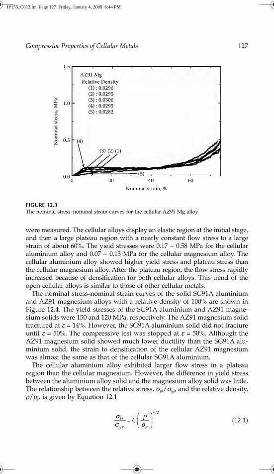
Compressive Properties of Cellular Metals
127
were measured. The cellular alloys display an elastic region at the initial stage,and then a large plateau region with a nearly constant flow stress to a largestrain of about 60%. The yield stresses were 0.17 ~ 0.58 MPa for the cellularaluminium alloy and 0.07 ~ 0.13 MPa for the cellular magnesium alloy. Thecellular aluminium alloy showed higher yield stress and plateau stress thanthe cellular magnesium alloy. After the plateau region, the flow stress rapidlyincreased because of densification for both cellular alloys. This trend of theopen-cellular alloys is similar to those of other cellular metals.
The nominal stress
–
nominal strain curves of the solid SG91A aluminiumand AZ91 magnesium alloys with a relative density of 100% are shown inFigure 12.4. The yield stresses of the SG91A aluminium and AZ91 magne-sium solids were 150 and 120 MPa, respectively. The AZ91 magnesium solidfractured at
e
= 14%. However, the SG91A aluminium solid did not fractureuntil
e
= 50%. The compressive test was stopped at
e
= 50%. Although theAZ91 magnesium solid showed much lower ductility than the SG91A alu-minium solid, the strain to densification of the cellular AZ91 magnesiumwas almost the same as that of the cellular SG91A aluminium.
The cellular aluminium alloy exhibited larger flow stress in a plateauregion than the cellular magnesium. However, the difference in yield stressbetween the aluminium alloy solid and the magnesium alloy solid was little.The relationship between the relative stress,
s
pl
/
s
ys
, and the relative density,
r
/
r
s
, is given by Equation 12.1
(12.1)
FIGURE 12.3
The nominal stress–nominal strain curves for the cellular AZ91 Mg alloy.
1.5
1.0
AZ91 MgRelative Density
(1) : 0.0296(2) : 0.0295(3) : 0.0306(4) : 0.0295(5) : 0.0282
(4)(3) (2) (1)
(5)
0.5
0.0 0 20 40Nominal strain, %
Nom
inal
stres
s, M
Pa
60
σσ
ρρ
pl
ys sC
, ,=
⎛⎝⎜
⎞⎠⎟
3 2/
IP155_C012.fm Page 127 Friday, January 4, 2008 6:44 PM
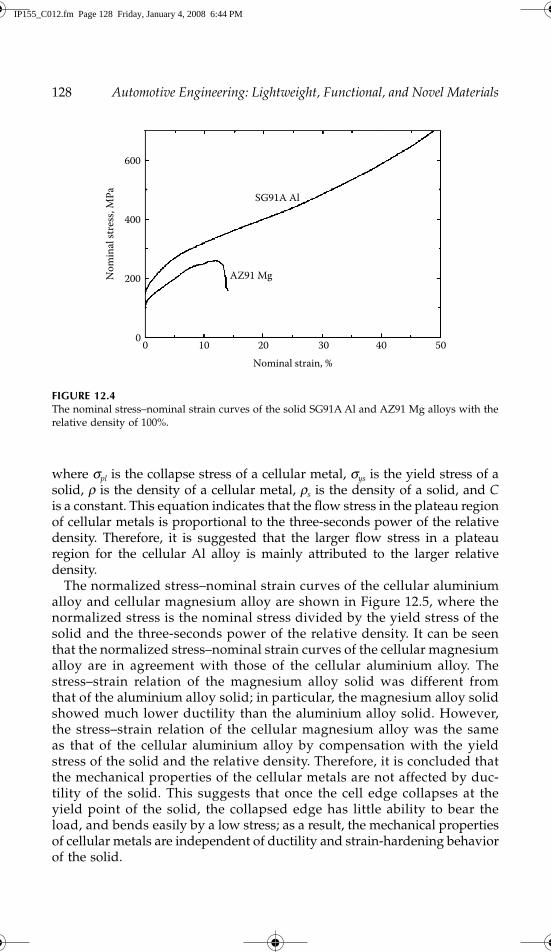
128
Automotive Engineering: Lightweight, Functional, and Novel Materials
where
s
pl
is the collapse stress of a cellular metal,
s
ys
is the yield stress of asolid,
r
is the density of a cellular metal,
r
s
is the density of a solid, and
C
is a constant. This equation indicates that the flow stress in the plateau regionof cellular metals is proportional to the three-seconds power of the relativedensity. Therefore, it is suggested that the larger flow stress in a plateauregion for the cellular Al alloy is mainly attributed to the larger relativedensity.
The normalized stress–nominal strain curves of the cellular aluminiumalloy and cellular magnesium alloy are shown in Figure 12.5, where thenormalized stress is the nominal stress divided by the yield stress of thesolid and the three-seconds power of the relative density. It can be seenthat the normalized stress–nominal strain curves of the cellular magnesiumalloy are in agreement with those of the cellular aluminium alloy. Thestress–strain relation of the magnesium alloy solid was different fromthat of the aluminium alloy solid; in particular, the magnesium alloy solidshowed much lower ductility than the aluminium alloy solid. However,the stress–strain relation of the cellular magnesium alloy was the sameas that of the cellular aluminium alloy by compensation with the yieldstress of the solid and the relative density. Therefore, it is concluded thatthe mechanical properties of the cellular metals are not affected by duc-tility of the solid. This suggests that once the cell edge collapses at theyield point of the solid, the collapsed edge has little ability to bear theload, and bends easily by a low stress; as a result, the mechanical propertiesof cellular metals are independent of ductility and strain-hardening behaviorof the solid.
FIGURE 12.4
The nominal stress–nominal strain curves of the solid SG91A Al and AZ91 Mg alloys with therelative density of 100%.
600
400
200
0 0 10 20
SG91A Al
AZ91 Mg
Nominal strain, %
Nom
inal
stre
ss, M
Pa
30 40 50
IP155_C012.fm Page 128 Friday, January 4, 2008 6:44 PM

Compressive Properties of Cellular Metals
129
Effect of the Cell Structure
Three kinds of open-cellular magnesium alloys—type A is a cellular mag-nesium alloy with random cell structure; type B is a cellular magnesiumalloy with controlled cell structure for which an angle between the strutsand the load direction is 45°; and type C is a cellular magnesium alloy withcontrolled cell structure for which an angle between the struts and the loaddirection is 0° (90°)—were fabricated by casting
3
(see Figure 12.6).The nominal stress–nominal strain curves of the cellular magnesium alloys
by compressive tests are shown in Figure 12.7. The type B structure showedalmost the same stress
–
strain curve as the type A structure, indicating thatthe dominant deformation mode of a cellular magnesium alloy with randomcell structure is the same as that of a cellular magnesium alloy with con-trolled cell structure for which an angle between the struts and the loaddirection is 45°. The collapse stresses were about 0.1 MPa for the type A andthe type B structures. For the type C structure, however, the flow stressdecreased after a sharp peak, and then it rapidly increased with increasingstrain. This fluctuation of the flow stress is repeated in the plateau region. Thistrend is the same as that in the cellular epoxy.
4
The collapse stress (first peakstress) was 0.4 MPa for the type C structure. The collapse stress of the type Cstructure was 4 times higher than those for the type A and the type Bstructures. Recently, Markaki and Clyne
5
revealed that the mechanical prop-erties of a cellular aluminium alloy were strongly affected by the microstruc-ture. In the present investigation, however, the density and microstructure
FIGURE 12.5
The normalized stress–nominal strain curves of the cellular SG91A Al alloy and cellular AZ91Mg alloy.
1.5
1.0
SG91A AlRelative Density
(1) : 0.0653(2) : 0.0446(3) : 0.0580(4) : 0.0471(5) : 0.0573
(1)
(4)(3)
(5)(2)
0.5
0.00 20 40
Nominal strain, %
Nom
inal
stre
ss, M
Pa
60
IP155_C012.fm Page 129 Friday, January 4, 2008 6:44 PM
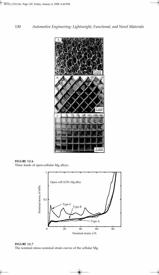
130
Automotive Engineering: Lightweight, Functional, and Novel Materials
FIGURE 12.6
Three kinds of open-cellular Mg alloys.
FIGURE 12.7
The nominal stress–nominal strain curves of the cellular Mg.
A
B
C
5 mm
5 mm
5 mm
Nominal strain, ε/%0 20 40 60 80
0.5
Open-cell AZ91 Mg alloy
Type CType B
Type A
1
Nom
inal
stre
ss, σ
/MPa
IP155_C012.fm Page 130 Friday, January 4, 2008 6:44 PM
Compressive Properties of Cellular Metals
131
of the cellular magnesium alloys were the same. Clearly, the cell structurestrongly affects the collapse stress in the plateau region of cellular metals.
Another important result shown in Figure 12.7 is that the densification strain,which is the strain to the onset of the densification region, is almost the samefor three kinds of cellular magnesium alloys. That is to say that the densifi-cation strain is not affected by the cell structure. It is, therefore, suggested thatthe densification strain mainly depends on the relative density of the material.
Summary
The stress–strain relation of cellular magnesium alloy was almost the sameas that of the cellular Al alloy by compensation with the yield stress of thesolid and the relative density. Therefore, it is concluded that the mechanicalproperties of the cellular metals are not affected by ductility of the solid. Thecell structure strongly affected the collapse stress in the plateau region ofcellular metals. However, the densification strain was not affected by the cellstructure.
References
1. Gibson, L. J., and M. F. Ashby,
Cellular Solids, Structure and Properties
, CambridgeUniversity Press, Cambridge, 175, 1997.
2. Yamada, Y., et al.,
Mater. Sci. Eng. A
, A272, 455, 1999.3. Yamada, Y., et al.,
Mater. Trans
., in press, 2002.4. Yamada, Y., et al.,
Philos. Mag. Lett
., Vol. 80, 215, 2000.5. Markaki, A. E., and T. W. Clyne,
Acta Mater
., Vol. 49, 1677, 2001.
IP155_C012.fm Page 131 Friday, January 4, 2008 6:44 PM

IP155_C012.fm Page 132 Friday, January 4, 2008 6:44 PM

133
13
Heavily Deformable Al Alloy
Osamu Umezawa
CONTENTS
A Recyclable Design for Sustainable Development......................................133Problems in Scrap Metal Recycling ........................................................133Upgrade Recycle Design for Al-Si-X Alloys .........................................134
Fine Microstructure Development ...................................................................134Concept of Mesocomplex Structure.................................................................136Repeated Thermomechanical Treatment.........................................................136Fragmentation of Silicon and Compounds ....................................................138Plasticity and Tensile Properties ......................................................................140Fatigue Strength and Crack Generation .........................................................142Technological Applications ...............................................................................144Summary ..............................................................................................................147References............................................................................................................ 147
A Recyclable Design for Sustainable Development
Problems in Scrap Metal Recycling
Products generally consist of many kinds of materials. However, it is neces-sary to save resources and energy, and so there is a general move towardthe use of recycled materials. Engineering challenges for the ideal recyclingsystem are to reduce impurity content from scrap melt, to immunize metalsagainst impurities or make metals innocuous to impurities, and finally, toreplace conventional metals with inherently recyclable metals. As a design for
ecomaterials
(environment conscious materials)
1
recyclable design for sustainabledevelopment has been proposed, where the materials and products are in har-mony with the natural environment and provide a simplified recycling route.The concept has been discussed from the point of view of design factors, i.e.,
IP155_C013.fm Page 133 Monday, December 31, 2007 4:59 PM

134
Automotive Engineering: Lightweight, Functional, and Novel Materials
recyclability and ecology for raw materials, and simplification of recycling andscrapping, balanced against the desired properties.
2
Aluminum products, aswell as steels, are some of the early metals that have taken up the challenge ofrecycling. In the case of aluminum, recycling is desirable, since producing alu-minum from virgin mineral sources, such as bauxite, consumes large amountsof energy. However, the incorporation of secondary (scrap) aluminum has beenalmost limited to cast materials, and dilution with raw material has been inev-itable. In the 1990s, about 30% by weight of aluminum products were producedfrom scrap metals in Japan. The use of scrap metal will increase, so secondarymetal products should be manufactured not only using cast materials, but also,wrought ones.
Upgrade Recycle Design for Al-Si-X Alloys
In the case of aluminum, silicon, iron, and copper, are major detrimentalelements for recycling aluminum products. Silicon and iron presents prob-lems in aluminum alloy recycling due to the poor workability of aluminumincorporating these elements, and the general difficulty in removing themfrom stock materials. Al-Si-X alloys are one of the major cast material sys-tems, and include almost no undesirable elements for the classification
ecomaterial
. However, removal of Si and Fe from scrapped aluminum prod-ucts is difficult and costly. The Al-Si system has multiple phases with lowmutual solid solubility, and are effectively an in-situ metal-metal composite,making it an ideal model for recycling whilst maintaining control of thebalance of properties, such as strength and elongation, without detrimentalelements for the
ecomaterials;
fine microstructure with plural phases,
mesocom-plex structure,
is one of the candidates for alloy design.
2
Hence, Al-Si basedalloys have great advantage in recyclable material design. However, heavycold-working cannot be used, since this would cause severe cracking in theprimary Si crystals and coarse intermetallic compounds.
Fine Microstructure Development
To improve the mechanical properties of Al-Si-X cast materials, microstruc-tural modifications have been commonly achieved by the addition of ele-ments such as strontium and phosphorus into the melt, or by hot-forgingand subsequent long solution heat-treatment, as shown in Figure 13.1. How-ever, the ductility of these treated materials is not enough, and it is difficultto apply these treatments to wrought materials. Coarse silicon crystalsand/or acicular Al-Si-Fe intermetallic compounds cause poor ductility andoften give rise to fatigue crack initiation sites, as well as inclusions. Toimprove the workability and mechanical properties, the silicon crystals andcompounds must be refined to avoid sample fracture due to their cracking.
IP155_C013.fm Page 134 Monday, December 31, 2007 4:59 PM
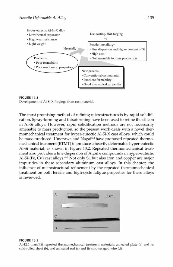
Heavily Deformable Al Alloy
135
The most promising method of refining microstructures is by rapid solidifi-cation. Spray-forming and thixoforming have been used to refine the siliconin Al-Si alloys. However, rapid solidification methods are not necessarilyamenable to mass production, so the present work deals with a novel ther-momechanical treatment for hyper-eutectic Al-Si-X cast alloys, which couldbe mass produced. Umezawa and Nagai
3–4
have proposed repeated thermo-mechanical treatment (RTMT) to produce a heavily deformable hyper-eutecticAl-Si material, as shown in Figure 13.2. Repeated thermomechanical treat-ment also provides a fine dispersion of Al
5
SiFe compounds in hyper-eutecticAl-Si-(Fe, Cu) cast alloys.
4–6
Not only Si, but also iron and copper are majorimpurities in these secondary aluminum cast alloys. In this chapter, theinfluence of microstructural refinement by the repeated thermomechanicaltreatment on both tensile and high-cycle fatigue properties for these alloysis reviewed.
FIGURE 13.1
Development of Al-Si-X forgings from cast material.
FIGURE 13.2
Al-12.6 mass%Si repeated thermomechanical treatment materials: annealed plate (a) and itscold-rolled sheet (b), and annealed rod (c) and its cold-swaged wire (d).
Hyper-eutectic Al-Si-X alloyLow thermal expansion High wear resistanceLight weight
ProblemsPoor formabilityPoor mechanical properties
Powder metallurgyFine dispersion and higher content of SiHigh cost Not amenable to mass production
Die-casting, Hot-forgingvs
Normally
New processConventional cast materialExcellent formabilityGood mechanical properties
A
B
5 cm
C
D
IP155_C013.fm Page 135 Monday, December 31, 2007 4:59 PM
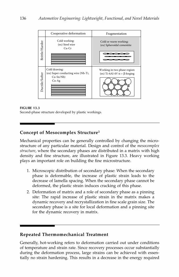
136
Automotive Engineering: Lightweight, Functional, and Novel Materials
Concept of Mesocomplex Structure
2
Mechanical properties can be generally controlled by changing the micro-structure of any particular material. Design and control of the
mesocomplexstructure
, where the secondary phases are distributed in a matrix with highdensity and fine structure, are illustrated in Figure 13.3. Heavy workingplays an important role on building the fine microstructure.
1. Microscopic distribution of secondary phase: When the secondaryphase is deformable, the increase of plastic strain leads to thedecrease of lamella spacing. When the secondary phase cannot bedeformed, the plastic strain induces cracking of this phase.
2. Deformation of matrix and a role of secondary phase as a pinningsite: The rapid increase of plastic strain in the matrix makes adynamic recovery and recrystallization in fine scale grain size. Thesecondary phase is a site for local deformation and a pinning sitefor the dynamic recovery in matrix.
Repeated Thermomechanical Treatment
Generally, hot-working refers to deformation carried out under conditionsof temperature and strain rate. Since recovery processes occur substantiallyduring the deformation process, large strains can be achieved with essen-tially no strain hardening. This results in a decrease in the energy required
FIGURE 13.3
Second-phase structure developed by plastic workings.
Cooperative deformation Fragmentation
Duc
tile/
Softe
rBr
ittle
/Har
der Cold working:
(ex) Steel wire Cu-Cr
Cold drawing:(ex) Super conducting wire (Nb-Ti,
Cu-Sn/Nb)Cu-Ag
Cold or warm working:(ex) Spheroidal cementite
Working in two phase region:(ex) Ti-6Al-4V α + β forging
IP155_C013.fm Page 136 Monday, December 31, 2007 4:59 PM
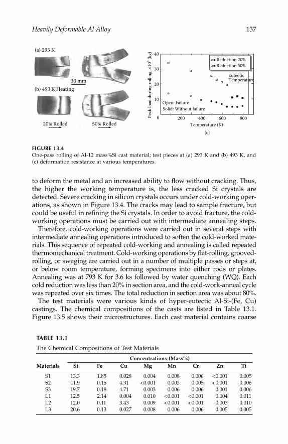
Heavily Deformable Al Alloy
137
to deform the metal and an increased ability to flow without cracking. Thus,the higher the working temperature is, the less cracked Si crystals aredetected. Severe cracking in silicon crystals occurs under cold-working oper-ations, as shown in Figure 13.4. The cracks may lead to sample fracture, butcould be useful in refining the Si crystals. In order to avoid fracture, the cold-working operations must be carried out with intermediate annealing steps.
Therefore, cold-working operations were carried out in several steps withintermediate annealing operations introduced to soften the cold-worked mate-rials. This sequence of repeated cold-working and annealing is called repeatedthermomechanical treatment. Cold-working operations by flat-rolling, grooved-rolling, or swaging are carried out in a number of multiple passes or steps at,or below room temperature, forming specimens into either rods or plates.Annealing was at 793 K for 3.6 ks followed by water quenching (WQ). Eachcold reduction was less than 20% in section area, and the cold-work-anneal cyclewas repeated over six times. The total reduction in section area was about 80%.
The test materials were various kinds of hyper-eutectic Al-Si-(Fe, Cu)castings. The chemical compositions of the casts are listed in Table 13.1.Figure 13.5 shows their microstructures. Each cast material contains coarse
FIGURE 13.4
One-pass rolling of Al-12 mass%Si cast material; test pieces at (a) 293 K and (b) 493 K, and(c) deformation resistance at various temperatures.
TABLE 13.1
The Chemical Compositions of Test Materials
Concentrations (Mass%)Materials Si Fe Cu Mg Mn Cr Zn Ti
S1 13.3 1.85 0.028 0.004 0.008 0.006
<
0.001 0.005S2 11.9 0.15 4.31
<
0.001 0.003 0.005
<
0.001 0.006S3 19.7 0.18 4.71 0.003 0.006 0.006 0.001 0.006L1 12.5 2.14 0.004 0.010
<
0.001
<
0.001 0.004 0.011L2 12.0 0.11 3.43 0.009
<
0.001
<
0.001 0.003 0.010L3 20.6 0.13 0.027 0.008 0.006 0.006 0.005 0.005
10 Open: Failure
20
30
40(a) 293 K
(b) 493 K Heating30 mm
20% Rolled 50% Rolled0 200 400 600 800Pe
ak lo
ad d
urin
g ro
lling
, ×10
3 (kg)
Temperature (K)
Solid: Without failure
Reduction 20% Reduction 50%
EutecticTemperature
(c)
IP155_C013.fm Page 137 Monday, December 31, 2007 4:59 PM
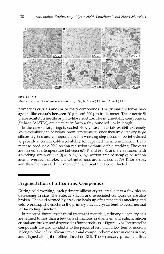
138
Automotive Engineering: Lightweight, Functional, and Novel Materials
primary Si crystals and/or primary compounds. The primary Si forms hex-agonal-like crystals between 20
μ
m and 200
μ
m in diameter. The eutectic Siphase exhibits a needle or plate-like structure. The intermetallic compounds,
β
phase (Al
5
SiFe), are acicular in form a few hundred
μ
m in length.In the case of large ingots cooled slowly, cast materials exhibit extremely
low workability at, or below, room temperature, since they involve very largesilicon crystals and compounds. A hot-working step needs to be introducedto provide a certain cold-workability for repeated thermomechanical treat-ment to produce a 20% section reduction without visible cracking. The castsare heated at a temperature between 673 K and 693 K, and are extruded witha working strain of 0.97 (
η
=
ln A
0
/A, A
0
: section area of sample; A: sectionarea of worked sample). The extruded rods are annealed at 793 K for 3.6 ks,and then the repeated thermomechanical treatment is conducted.
Fragmentation of Silicon and Compounds
During cold-working, each primary silicon crystal cracks into a few pieces,decreasing in size. The eutectic silicon and associated compounds are alsobroken. The void formed by cracking heals up after repeated annealing andcold-working. The cracks in the primary silicon crystal tend to occur normalto the rolling direction.
In repeated thermomechanical treatment materials, primary silicon crystalsare refined to less than a few tens of microns in diameter, and eutectic siliconcrystals are broken and dispersed as fine particles (see Figure 13.6). Intermetalliccompounds are also divided into the pieces of less than a few tens of micronsin length. Most of the silicon crystals and compounds are a few microns in size,and aligned along the rolling direction (RD). The secondary phases are thus
FIGURE 13.5
Microstructures of cast materials: (a) S1, (b) S2, (c) S3, (d) L1, (e) L2, and (f) L3.
A B
200 μm
100 μm
100 μm
100 μm
100 μm
100 μm
D E
C
F
IP155_C013.fm Page 138 Monday, December 31, 2007 4:59 PM

Heavily Deformable Al Alloy
139
distributed in the matrix with high density and fine size. In addition, they arespheroidized. In slowly cooled casts, however, the fragmentation and disper-sion of primary Si crystals and/or compounds in the aluminum matrix throughrepeated thermomechanical treatment are insufficient for most applications(Figure 13.6d–f). The cracks in the primary Si remain, and are not fully filledby the aluminum matrix during repeated thermomechanical treatment.
When the secondary silicon phase in the soft Al matrix is non-deforming, theplastic work causes cracking in this secondary phase. The succeeding heattreatment softens the aluminum matrix again, as illustrated in Figure 13.7. Sincethe liner thermal expansion coefficient of aluminum is much higher than that
FIGURE 13.6
Microstructures of repeated thermomechanical treatment materials in the longitudinal section:(a) 13Si-2Fe, (b) 12Si-4Cu, (c) 20Si-4Cu, (d) 13Si-2Fe: L1, (e) 12Si-4Cu: L2, and (f) 20Si: L3.Photographs d–f show the casts cooled slowly. Arrows show the longitudinal direction.
FIGURE 13.7
Schematic illustration of silicon cracking and Al matrix annealing: (a) thermal expansion coef-ficient of aluminium and silicon, and (b) silicon cracking temperature.
A B
50 μm 50 μm 50 μm
100 μm 100 μm 100 μm
C
D E F
200 400 600 8000
(a)
30
20
10
0
Coeffi
cien
t of
linea
r the
rmal
expa
nsio
n,×
10–6
(deg
–1)
Si
Al
Working operation
Heat treatment
RDPrimary Si
Cracked
Healed
Spheroidized
Eutectic SiDividedStrained
AnnealedRepeat
Temperature (K) Temperature (K)
20
50
200 400 600 800Redu
ctio
n by
one
-pas
s rol
ling
(%)
Failure
Eutectic Si: Divided
Primary Si: Cracking
0
(b)
IP155_C013.fm Page 139 Monday, December 31, 2007 4:59 PM
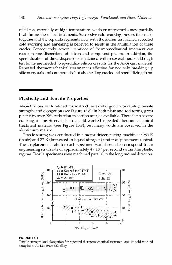
140
Automotive Engineering: Lightweight, Functional, and Novel Materials
of silicon, especially at high temperature, voids or microcracks may partiallyheal during these heat treatments. Successive cold working presses the crackstogether and the separate segments flow with the aluminum. Hence, repeatedcold working and annealing is believed to result in the annihilation of thesecracks. Consequently, several iterations of thermomechanical treatment canresult in fine dispersions of silicon and compound phases. In addition, thesperoidization of these dispersions is attained within several hours, althoughten hours are needed to speroidize silicon crystals for the Al-Si cast material.Repeated thermomechanical treatment is effective for not only breaking upsilicon crystals and compounds, but also healing cracks and speroidizing them.
Plasticity and Tensile Properties
Al-Si-X alloys with refined microstructure exhibit good workability, tensilestrength, and elongation (see Figure 13.8). In both plate and rod forms, greatplasticity, over 90% reduction in section area, is available. There is no severecracking in the Si crystals in a cold-worked repeated thermomechanicaltreatment material (see Figure 13.9), but many voids are observed in thealuminium matrix.
Tensile testing was conducted in a motor-driven testing machine at 293 K(in air) and 77 K (immersed in liquid nitrogen) under displacement control.The displacement rate for each specimen was chosen to correspond to anengineering strain rate of approximately 4
×
10
−
4
per second within the plasticregime. Tensile specimens were machined parallel to the longitudinal direction.
FIGURE 13.8
Tensile strength and elongation for repeated thermomechanical treatment and its cold-workedsamples of Al-12.6 mass%Si alloy.
Working strain, η
Ulti
mat
e ten
sile s
tren
gth,
σB
(MPa
) 400
300
200
100
0 1 2 3 4 5
40
30
20
10
0
Tota
l elo
ngat
ion,
El (
%)
RTMTSwaged for RTMT Rolled for RTMT As cast
Cold-worked RTMT
σBOpenSolid: El
IP155_C013.fm Page 140 Monday, December 31, 2007 4:59 PM

Heavily Deformable Al Alloy
141
All cast materials showed poor elongation and early fracture caused bycracking of the secondary phase. Although the ultimate tensile strength ofthe repeated thermomechanical treatment material was almost the same asthat of the cast one, the elongation of the repeated thermomechanical treat-ment material was much higher than that of the cast one, as shown in Figure13.10. Local elongation and uniform elongation increase with repeated ther-momechanical treatment. At lower temperatures, especially, microstructuralrefinement could result in the avoidance of early fracture as observed forthe cast material. An increase in the flow stress with decreasing temperatureresults in a greater strain to failure for the repeated thermomechanical treat-ment samples. In general, increases in the strain hardening rate lead to anincrease in the strain to failure. A geometrical instability occurs in a tensiletest when the strain hardening rate equals the true stress. The repeatedthermomechanical treatment samples show the necking instability, but thecast samples fractured before reaching it (see Figure 13.11). Therefore, therepeated thermomechanical treatment materials have a significantlyenhanced ductility and strength, since early fracture is overcome in the
FIGURE 13.9
SEM micrographs of a cold-rolled repeated thermomechanical treatment sample (
η
=
3): (a)back scatter image for the RD section
,
and (b) secondary electron image for the TD section.
FIGURE 13.10
Stress–strain curves of Al-12.6 mass%Si alloy.
TD TD Si
Void
RD
10 μm
A B RD
50 μm
400
300
200
100
0 0.05 0.1 0.15 0.2Engineering strain
Engi
neer
ing
stre
ss (M
Pa)
As cast
0.25
Cold-working (swaging)
RTMTη = 0
77 K293 K
η = 1.35
IP155_C013.fm Page 141 Monday, December 31, 2007 4:59 PM

142
Automotive Engineering: Lightweight, Functional, and Novel Materials
repeated thermomechanical treatment condition. Microstructural modifica-tion by repeated thermomechanical treatment is effective in improving ten-sile properties.
Figure 13.12 shows elemental maps obtained by electron probe micro-analysis, and the fracture surfaces obtained from tensile testing Al-7 mass %,Si-1 mass %, and Fe alloy in both as-cast and cold-worked conditions. Althoughthe cast material exhibits a brittle feature, the cold-worked material showsa ductile one, reflecting the microstructural differences in the two materials.
Fatigue Strength and Crack Generation
Using a servo hydraulic fatigue test machine, load-controlling fatigue testsfor the large cast materials and their repeated thermomechanical treatmentones were carried out with a stress ratio, R (
σ
min
/
σ
max
) = 0.01, supplied asa sine wave at, and below, 296 K. No large difference in fatigue strengthwas observed in either the low cycle or high cycle regime (see Figure 13.13).
FIGURE 13.11
True stress
–
true plastic strain curves and strain-hardening rate curves from data in Figure 13.10:(a) as cast, (b) repeated thermomechanical treatment samples at 293 K, and (c) repeated ther-momechanical treatment samples at 77 K.
True
stre
ss, σ
(MPa
) St
rain
-har
deni
ng ra
te, θ
(MPa
)
True strain, ε True strain, ε
σ
θ
10,000
1000
100
100.10.050 0.025 0.075
10,000
1000
100
100.10.050 0.15 0.2 0.10.050 0.15 0.2
(a) AC
77 K
(b) RTMT, 293K (c) RTMT, 77K
η = 1.35
293 K
η = 0η = 0
θ
Early fracture
Plastic instability
η = 1.35
θ
σ
σ
(b)
(a)
(c)
IP155_C013.fm Page 142 Monday, December 31, 2007 4:59 PM
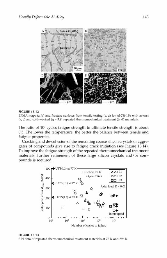
Heavily Deformable Al Alloy
143
The ratio of 10
7
cycles fatigue strength to ultimate tensile strength is about0.5. The lower the temperature, the better the balance between tensile andfatigue properties.
Cracking and de-cohesion of the remaining coarse silicon crystals or aggre-gates of compounds give rise to fatigue crack initiation (see Figure 13.14).To improve the fatigue strength of the repeated thermomechanical treatmentmaterials, further refinement of these large silicon crystals and/or com-pounds is required.
FIGURE 13.12
EPMA maps (a, b) and fracture surfaces from tensile testing (c, d) for Al-7Si-1Fe with as
-
cast(a, c) and cold-worked (
η
=
5.8) repeated thermomechanical treatment (b, d) materials.
FIGURE 13.13
S-N data of repeated thermomechanical treatment materials at 77 K and 296 K.
A B
C D
Beta (Al5SiFe)
Eutectic Si
10 μm
10 μm 10 μm
RD
500
400
300
200
100
0103 104 105 106 107
Number of cycles to failure
Peak
cycl
ic st
ress
, σm
ax (M
Pa)
Axial load, R = 0.01
: L1: L2: L3
Hutched: 77 K Open: 296 K
Interrupted
UTS(L2) at 77 K
UTS(L1) at 77 K
UTS(L3) at 77 K
IP155_C013.fm Page 143 Monday, December 31, 2007 4:59 PM
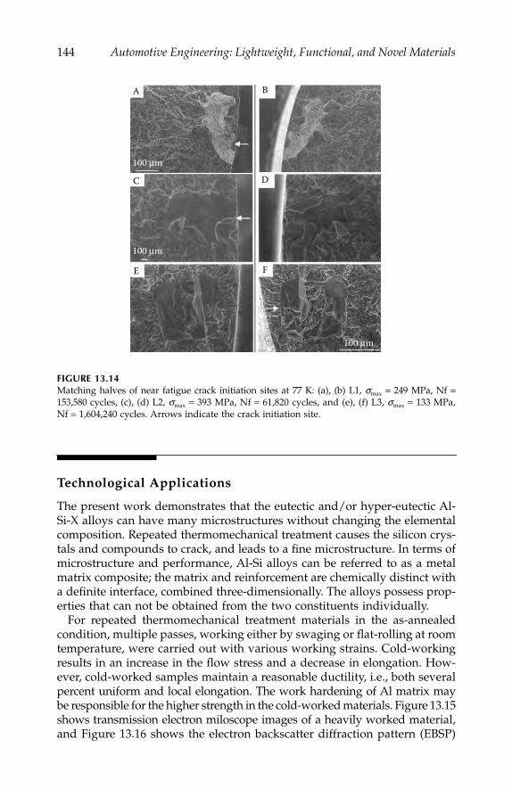
144
Automotive Engineering: Lightweight, Functional, and Novel Materials
Technological Applications
The present work demonstrates that the eutectic and/or hyper-eutectic Al-Si-X alloys can have many microstructures without changing the elementalcomposition. Repeated thermomechanical treatment causes the silicon crys-tals and compounds to crack, and leads to a fine microstructure. In terms ofmicrostructure and performance, Al-Si alloys can be referred to as a metalmatrix composite; the matrix and reinforcement are chemically distinct witha definite interface, combined three-dimensionally. The alloys possess prop-erties that can not be obtained from the two constituents individually.
For repeated thermomechanical treatment materials in the as-annealedcondition, multiple passes, working either by swaging or flat-rolling at roomtemperature, were carried out with various working strains. Cold-workingresults in an increase in the flow stress and a decrease in elongation. How-ever, cold-worked samples maintain a reasonable ductility, i.e., both severalpercent uniform and local elongation. The work hardening of Al matrix maybe responsible for the higher strength in the cold-worked materials. Figure 13.15shows transmission electron miloscope images of a heavily worked material,and Figure 13.16 shows the electron backscatter diffraction pattern (EBSP)
FIGURE 13.14
Matching halves of near fatigue crack initiation sites at 77 K: (a), (b) L1,
σ
max
=
249 MPa, Nf
=
153,580 cycles, (c), (d) L2,
σ
max
=
393 MPa, Nf
=
61,820 cycles, and (e), (f) L3,
σ
max
=
133 MPa,Nf
=
1,604,240 cycles. Arrows indicate the crack initiation site.
A
100 μm
100 μm
100 μm
B
C D
E F
IP155_C013.fm Page 144 Monday, December 31, 2007 4:59 PM
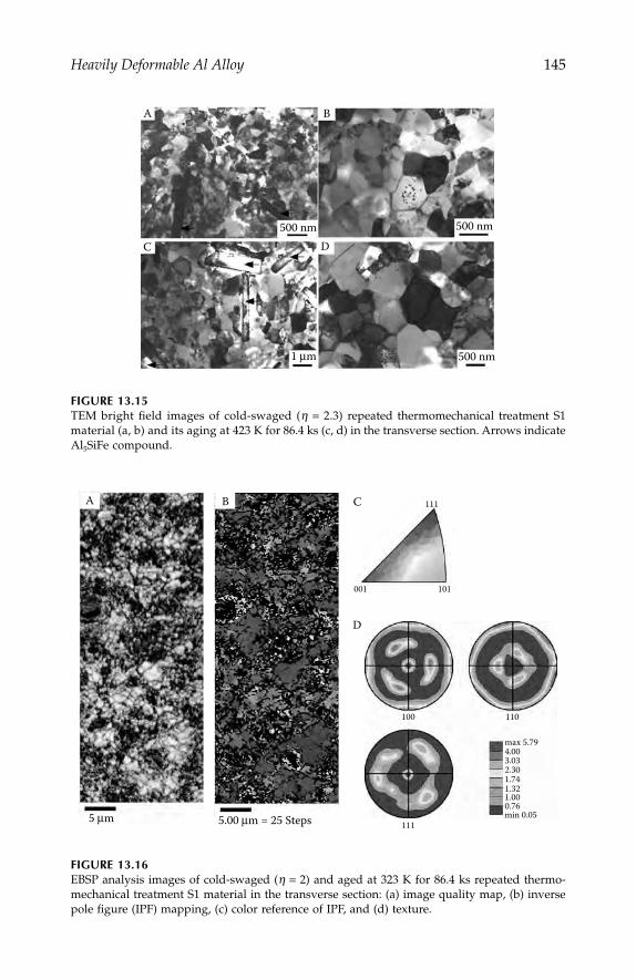
Heavily Deformable Al Alloy
145
FIGURE 13.15
TEM bright field images of cold-swaged (
η
=
2.3) repeated thermomechanical treatment S1material (a, b) and its aging at 423 K for 86.4 ks (c, d) in the transverse section. Arrows indicateAl
5
SiFe compound.
FIGURE 13.16
EBSP analysis images of cold-swaged (
η
=
2) and aged at 323 K for 86.4 ks repeated thermo-mechanical treatment S1 material in the transverse section: (a) image quality map, (b) inversepole figure (IPF) mapping, (c) color reference of IPF, and (d) texture.
A B
C D500 nm 500 nm
500 nm1 μm
A
5 μm
B C
D
5.00 μm = 25 Steps
001
100
111
110
max 5.79
min 0.05
4.003.032.301.741.321.000.76
101
111
IP155_C013.fm Page 145 Monday, December 31, 2007 4:59 PM
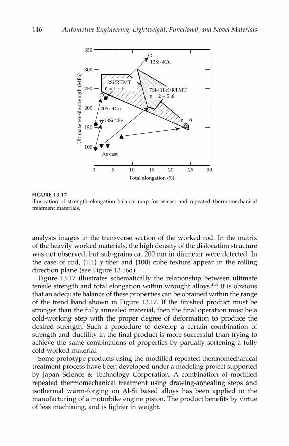
146
Automotive Engineering: Lightweight, Functional, and Novel Materials
analysis images in the transverse section of the worked rod. In the matrixof the heavily worked materials, the high density of the dislocation structurewas not observed, but sub-grains ca. 200 nm in diameter were detected. Inthe case of rod, {111}
γ
fiber and {100} cube texture appear in the rollingdirection plane (see Figure 13.16d).
Figure 13.17 illustrates schematically the relationship between ultimatetensile strength and total elongation within wrought alloys.
4–6
It is obviousthat an adequate balance of these properties can be obtained within the rangeof the trend band shown in Figure 13.17. If the finished product must bestronger than the fully annealed material, then the final operation must be acold-working step with the proper degree of deformation to produce thedesired strength. Such a procedure to develop a certain combination ofstrength and ductility in the final product is more successful than trying toachieve the same combinations of properties by partially softening a fullycold-worked material.
Some prototype products using the modified repeated thermomechanicaltreatment process have been developed under a modeling project supportedby Japan Science & Technology Corporation. A combination of modifiedrepeated thermomechanical treatment using drawing-annealing steps andisothermal warm-forging on Al-Si based alloys has been applied in themanufacturing of a motorbike engine piston. The product benefits by virtueof less machining, and is lighter in weight.
FIGURE 13.17
I
llustration of strength–elongation balance map for as-cast and repeated thermomechanicaltreatment materials.
0 5 10 15 20 25 30
350
300
250
200
150
100
Total elongation (%)
Ulti
mat
e ten
sile s
tren
gth
(MPa
) 12Si/RTMTη = 1 ~ 5
As cast
13Si-2Fe
12Si-4Cu
20Si-4Cu
7Si-(1Fe)/RTMTη = 2 ~ 5 .8
η = 0
IP155_C013.fm Page 146 Monday, December 31, 2007 4:59 PM

Heavily Deformable Al Alloy
147
Summary
A new design concept for a recyclable material has been proposed where acombination of multiple phases with fine microstructure is considered. Anovel repeated thermomechanical treatment, has been successful in achiev-ing microstructural refinement of hyper-eutectic Al-Si-(Fe, Cu) cast materialsleading to improved tensile properties. It raises the possibility of designingmaterials with balanced properties via cold-working. A modified repeatedthermomechanical treatment of Al-Si based alloys has been applied todevelop automotive forged parts, such as engine pistons.
References
1. Halada, K., and R. Yamamoto,
MRS Bulletin
, Nov., 871–879, 2001.2. For an example, Umezawa, O., and K. Nagai,
Trans. of MRS Japan
, Vol. 20,190–193, 1996.
3. Umezawa, O., and K. Nagai, Japan Patent Nos. 3005672 (1999), 3005673 (1999),and 3111214 (2000), in Japanese.
4. Umezawa, O., and K. Nagai,
Metall. Mater. Trans. A
, Vol. 30A, No. 8., 2221–2228,1999.
5. Lim, C. Y., O. Umezawa, and K. Nagai,
Metals and Materials
, Vl. 4, No. 5,1027–1031, 1998.
6. Umezawa, O., H. Yokoyama, and K. Nagai, “Advances in Materials Engineer-ing and Technology,”
Int. J. of Materials and Product Technology
, Special Issue,SPM1, Vol. 2, 568–573, 2001.
IP155_C013.fm Page 147 Monday, December 31, 2007 4:59 PM

IP155_C013.fm Page 148 Monday, December 31, 2007 4:59 PM

149
14
Stainless Steel Sandwich Sheets
with Fibrous Metal Cores
A. E. Markaki and Bill Clyne
CONTENTS
Introduction .........................................................................................................150Experimental Procedures...................................................................................151
Material Production...................................................................................151Through-Thickness Stiffness ....................................................................151Through-Thickness Yield Stress ..............................................................152Interfacial Fracture Energy.......................................................................153Single Fiber Tensile Testing......................................................................153Electrical Conductivity .............................................................................153Resistance Welding....................................................................................153Geometrical Representation of the Core Structure ..............................154
Through-Thickness Loading Response ...........................................................155Core Stiffness..............................................................................................155
Flocked Sheet and Long Fiber In-Plane Mesh .........................1553-D Random Fiber Array .............................................................157
Core Strength and Yielding Behavior.....................................................160Interfacial Fracture Energy.......................................................................162Fiber Pull-Out in Flocked Sheets ............................................................164Fiber Fracture in the In-Plane Mesh and 3-D Array ...........................165
Through-Thickness Electrical Resistance of the Core...................................168Flocked Sheet..............................................................................................168Brazed In-Plane Mesh and 3-D Array....................................................169Welding Characteristics ............................................................................170
Summary ..............................................................................................................172References.............................................................................................................174
IP155_C014.fm Page 149 Tuesday, January 8, 2008 11:21 AM

150
Automotive Engineering: Lightweight, Functional, and Novel Materials
Introduction
It has long been recognized that sandwich structures, composed of stiffouter layers held apart by a low density core, offer the potential for veryhigh specific stiffness and other attractive mechanical properties. Mostsuch structures are created by an assembly step of some sort, before orduring component manufacture. This limits the flexibility of the produc-tion process and is relatively expensive. Nevertheless, there is consider-able current interest in sandwich structures of different types, many ofthem based on metallic faceplates and having metal-containingcores—often made of stochastic cellular metals,
1–3
or some more regularstructure such as a truss assembly.
4–6
However, traditional approaches tothe fabrication of the latter (e.g., investment casting) are cumbersome andeconomically unattractive. A particular case of cellular metals is thosemade of a metallic fiber network of some sort. A novel type of a sandwichsteel sheet with a fibrous stainless steel core has recently been developed
7
based on a pair of thin (
~
200
μ
m) stainless steel faceplates. This materialhas been termed a hybrid stainless steel assembly (HSSA). It can, inprinciple, offer a highly attractive set of property combinations, such aslow areal density, high beam stiffness, efficient energy absorption duringcrushing, and good vibrational damping capacity. Furthermore, the over-all thickness of the sheet (
~
1 mm), and certain features of the core struc-ture, are such that its processing characteristics can be comparable withthose of a conventional monolithic metallic sheet. Some work has recentlybeen published on the elastic properties
8
and interfacial delaminationbehavior
9
of such material.In addition to mechanical stiffness and strength, electrical properties
are relevant, since efficient fabrication using steel sheets requires thatthey should be weldable, preferably by electrical resistance (spot) weld-ing. This is considered to be highly desirable for use in the automotiveindustry.
10
There has been extensive work on simulation of heat andcurrent flow during spot welding
11–14
on applied force characteristics,
15
and on welding of thin monolithic metallic sheets.
16
However, there isonly limited information available
17
on welding of metallic sandwichsheets with fibrous metallic cores, although there has been some work
18
on welding of vibration-damped steel. This consists of two mild steelsheets, typically 0.3 to 1 mm thick, separated by a thin layer of polymericadhesive (
~
20 to 500
μ
m).In this chapter, a study is presented of the mechanical and electrical
properties of three different variants of hybrid stanless steel assemblymaterial, and of their welding characteristics. Experimental data arecorrelated with predictions based on simple analytical treatments, andsome conclusions are drawn about the advantages and disadvantagesof the variants concerned.
IP155_C014.fm Page 150 Tuesday, January 8, 2008 11:21 AM
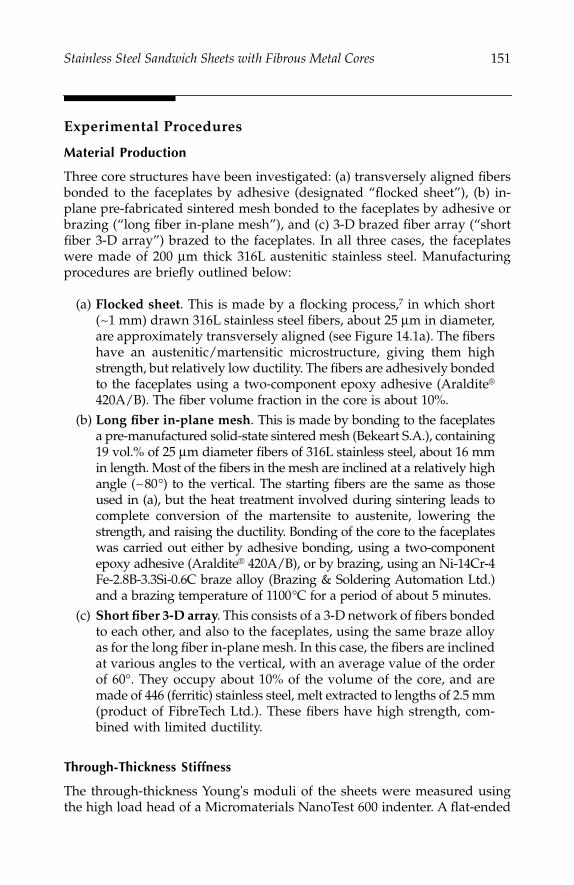
Stainless Steel Sandwich Sheets with Fibrous Metal Cores
151
Experimental Procedures
Material Production
Three core structures have been investigated: (a) transversely aligned fibersbonded to the faceplates by adhesive (designated “flocked sheet”), (b) in-plane pre-fabricated sintered mesh bonded to the faceplates by adhesive orbrazing (“long fiber in-plane mesh”), and (c) 3-D brazed fiber array (“shortfiber 3-D array”) brazed to the faceplates. In all three cases, the faceplateswere made of 200
μ
m thick 316L austenitic stainless steel. Manufacturingprocedures are briefly outlined below:
(a)
Flocked sheet
. This is made by a flocking process,
7
in which short(
~
1 mm) drawn 316L stainless steel fibers, about 25
μ
m in diameter,are approximately transversely aligned (see Figure 14.1a). The fibershave an austenitic/martensitic microstructure, giving them highstrength, but relatively low ductility. The fibers are adhesively bondedto the faceplates using a two-component epoxy adhesive (Araldite
®
420A/B). The fiber volume fraction in the core is about 10%.(b)
Long fiber in-plane mesh
. This is made by bonding to the faceplatesa pre-manufactured solid-state sintered mesh (Bekeart S.A.), containing19 vol.% of 25
μ
m diameter fibers of 316L stainless steel, about 16 mmin length. Most of the fibers in the mesh are inclined at a relatively highangle (
~
80°) to the vertical. The starting fibers are the same as thoseused in (a), but the heat treatment involved during sintering leads tocomplete conversion of the martensite to austenite, lowering thestrength, and raising the ductility. Bonding of the core to the faceplateswas carried out either by adhesive bonding, using a two-componentepoxy adhesive (Araldite
®
420A/B), or by brazing, using an Ni-14Cr-4Fe-2.8B-3.3Si-0.6C braze alloy (Brazing & Soldering Automation Ltd.)and a brazing temperature of 1100°C for a period of about 5 minutes.
(c)
Short fiber 3-D array
. This consists of a 3-D network of fibers bondedto each other, and also to the faceplates, using the same braze alloyas for the long fiber in-plane mesh. In this case, the fibers are inclinedat various angles to the vertical, with an average value of the orderof 60°. They occupy about 10% of the volume of the core, and aremade of 446 (ferritic) stainless steel, melt extracted to lengths of 2.5 mm(product of FibreTech Ltd.). These fibers have high strength, com-bined with limited ductility.
Through-Thickness Stiffness
The through-thickness Young's moduli of the sheets were measured usingthe high load head of a Micromaterials NanoTest 600 indenter. A flat-ended
IP155_C014.fm Page 151 Tuesday, January 8, 2008 11:21 AM
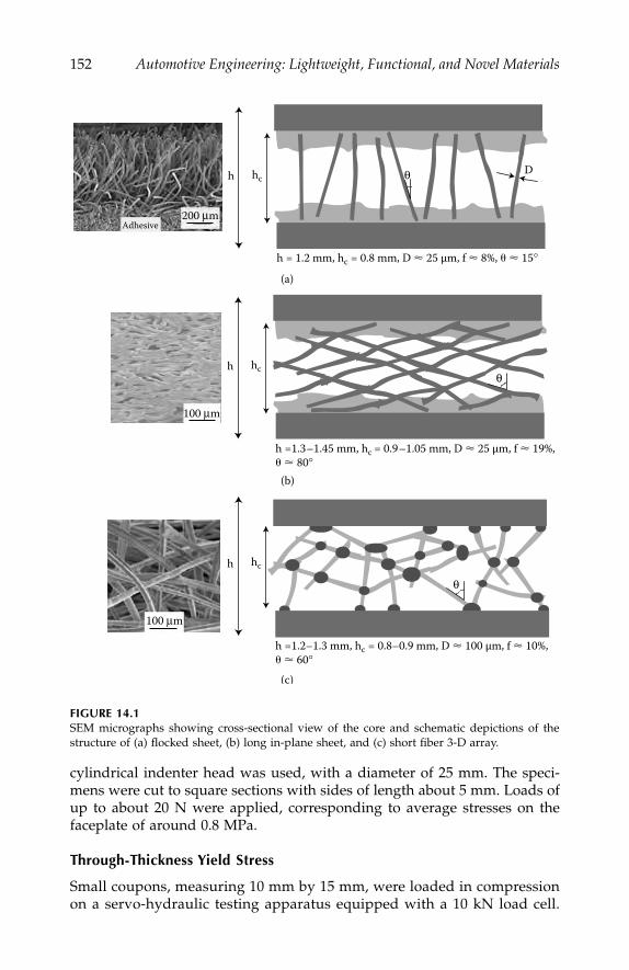
152
Automotive Engineering: Lightweight, Functional, and Novel Materials
cylindrical indenter head was used, with a diameter of 25 mm. The speci-mens were cut to square sections with sides of length about 5 mm. Loads ofup to about 20 N were applied, corresponding to average stresses on thefaceplate of around 0.8 MPa.
Through-Thickness Yield Stress
Small coupons, measuring 10 mm by 15 mm, were loaded in compressionon a servo-hydraulic testing apparatus equipped with a 10 kN load cell.
FIGURE 14.1
SEM micrographs showing cross-sectional view of the core and schematic depictions of thestructure of (a) flocked sheet, (b) long in-plane sheet, and (c) short fiber 3-D array.
(a)
(b)
(c)
hch D
h = 1.2 mm, hc = 0.8 mm, D � 25 μm, f � 8%, � � 15°
θ
Adhesive200 μm
hch
h =1.3–1.45 mm, hc = 0.9–1.05 mm, D � 25 μm, f � 19%,� � 80°
θ
100 μm
hch
h =1.2–1.3 mm, hc = 0.8–0.9 mm, D � 100 μm, f � 10%,� � 60°
100 μm
θ
IP155_C014.fm Page 152 Tuesday, January 8, 2008 11:21 AM
Stainless Steel Sandwich Sheets with Fibrous Metal Cores
153
The tests were conducted under controlled displacement rate of 0.15 mm.min
-
1
,and the through-thickness displacements were recorded from an LVDT(
±
500
μ
m range) with a resolution of about 5
µ
m. Attention was focused onidentification of the core yield stress, corresponding to the onset of substan-tial plastic bending and buckling among the fibers in the core.
Interfacial Fracture Energy
The resistance to delamination of the faceplates was measured under mode Iloading conditions. The test procedure employed
19
involves bonding of thesheet to two steel plates and loading these under pure bending, so as togenerate mode I crack growth. Prior to testing, a narrow pre-crack wasintroduced into the specimen at the mid-plane.
Single Fiber Tensile Testing
Single fiber testing was carried out using a Schenk desktop testing machine,fitted with a 5 or 250 N load cell. The individual fibers were mounted onpaper tabs, with a central cut-out that gave a gauge length of about 25 mm.The tab was gripped in the jaws of the testing machine; prior to testing, cutswere made from each side to the central cut-out. The cross-head displace-ment was measured using an LVDT. All tests were conducted in displace-ment control at a rate of 0.1 mm.min
-1
. Fibers were tested in the as-receivedcondition, and also after a heat treatment similar to those involved duringsolid-state sintering or brazing.
Electrical Conductivity
Specimens were in the form of small rectangular coupons (10
×
14 mm). AnAC circuit was used for the measurements. A fixed current (1 A) was passedthrough the specimen via flat-ended probes on the faceplates. This currentwas modulated at a constant frequency of 1 kHz. The potential drop acrossthe specimen, from which the resistivity of the core was deduced, was thenamplified and measured. In making this measurement, the potential dropacross other resistances in the sensing circuit must be eliminated. This dropgenerates an offset in the mean voltage of the AC signal. This DC offset wasremoved by passing the signal through an AC amplifier, after which it wasrectified by a demodulator, passed through an integrator to remove noise,and finally, displayed as a DC voltage (few mV to ~ 1 V for these specimens).Full details of the technique are given elsewhere.
20
Resistance Welding
Resistance welding trials were conduced on a single phase AC machine.Cu/Cr/Zr electrodes to ISO 5821 type E design were used, having 16 mmdiameter and 6 mm radius dome tip. An electrode force of 1.5 kN was used.
IP155_C014.fm Page 153 Tuesday, January 8, 2008 11:21 AM

154
Automotive Engineering: Lightweight, Functional, and Novel Materials
Single welds were made on small coupons. In cases where the core did notallow significant currents to flow at the low voltages used in resistance welding(typically about 5 V), a clamp tool was used to provide a current shunt path(in parallel with the electrodes) linking the outer sheet surfaces. This currentflow heated the specimen sufficiently to allow deformation of the core, andhence, direct flow through it, so that welding could be achieved. The weldingcurrent and voltage were measured using a standard meter and oscilloscope.
Geometrical Representation of the Core Structure
Simple analytical models have been developed, giving the fiber volumefraction
f
as a function of geometrical variables. For the flocked sheet core,a square array was assumed, with side of length
S
(Figure 14.2a). The fibervolume fraction is thus given by
(14.1)
where
D
is the fiber diameter. The number of fibers per unit area,
N,
is relatedto the fiber volume fraction
f
and the fiber diameter,
D
(14.2)
FIGURE 14.2
Schematic showing modeled fiber distributions for (a) the transverse fiber and (b) the sinteredmat (right) structures.
hc
D
R∗
S
(a)
Plan
Elevation
2L co
sθ
L
2L sinθ
θ
2L si
nθ
D
(b)
fDS
= π 2
24
NfD
= 42π
IP155_C014.fm Page 154 Tuesday, January 8, 2008 11:21 AM
Stainless Steel Sandwich Sheets with Fibrous Metal Cores
155
For the long fiber in-plane mesh, a tetragonal unit cell is identified, of side2
L.
sin
q
and height 2
L.
cos
q
, where
L
is the length of a segment of fiber havingone end at a cell corner and the other at the mid-point of a vertical face(Figure 14.2b). Each cell thus contains 16 fiber segments, all of which areshared between 2 cells. The fiber volume fraction and the number of fibersper unit area are thus given by
(14.3)
(14.4)
For the short fiber 3-D array, the relationship between
N
and
f
is simplyobtained by noting that, for a set of prisms with a 3-D random orientationdistribution of the prism axes, the area intersected by any plane is twice thearea intersected by a plane lying normal to the alignment direction of a setof parallel prisms occupying the same volume fraction.
21
Hence,
N
here hasa value of half that for the case of an aligned set of cylinders (
=
f
/(
π
D
2
/4)), i.e.,
(14.5)
Through-Thickness Loading Response
Core Stiffness
Two different approaches, based on a cantilever bending model, have beenused to predict the through-thickness stiffness of the sandwich sheet cores.The first is applicable for the flocked sheet and long fiber in-plane mesh, inwhich the fibers are inclined at a specified angle, whereas the secondapproach assumes a three-dimensionally random orientation distribution ofthe fiber axes (short fiber 3-D array).
Flocked Sheet and Long Fiber In-Plane Mesh
The Young’s modulus of the core in the through-thickness direction can bepredicted by considering the behavior of a single fiber of length
L
, initiallystraight and inclined at an angle
q
to the direction of the applied load. Thesituation under load is depicted schematically in Figure 14.3. All fibers
f
LD
L LD=
⎛⎝⎜
⎞⎠⎟
⎡
⎣⎢
⎤
⎦⎥
=8
4
2 2
2
2
π
θ θπ
( sin ) ( cos )
22
2 24L sin cosθ θ
NL
fD
= =42
42 2( sin )
cosθ
θπ
Nf
D= 2
2π
IP155_C014.fm Page 155 Tuesday, January 8, 2008 11:21 AM
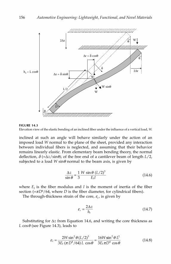
156
Automotive Engineering: Lightweight, Functional, and Novel Materials
inclined at such an angle will behave similarly under the action of animposed load
W
normal to the plane of the sheet, provided any interactionbetween individual fibers is neglected, and assuming that their behaviorremains linearly elastic. From elementary beam bending theory, the normaldeflection,
d
(=
Δ
z
/sin
q),
of the free end of a cantilever beam of length
L
/2,subjected to a load
W
sin
q
normal to the beam axis, is given by
(14.6)
where
E
f
is the fiber modulus and
I
is the moment of inertia of the fibersection (=
p
D
4
/64, where
D
is the fiber diameter, for cylindrical fibers).The through-thickness strain of the core,
e
c
, is given by
(14.7)
Substituting for
Δ
z
from Equation 14.6, and writing the core thickness as
L
cos
q
(see Figure 14.3), leads to
(14.8)
FIGURE 14.3
Elevation view of the elastic bending of an inclined fiber under the influence of a vertical load,
W
.
L/2W sinθ
W
hc = L cosθ
D
W
W
Δr = δ cosθ
Δz = δ sinθ
2Δz
2Δr
θ
θ
θ
δ
Δ =z W LE Isin
sin ( / )θ
θ13
2 3
f
ε cc
= 2Δzh
ε θπ θc
( / )( / )
= =2 23 64
163
4W L
E D LWsin
cos
2
f
ssincos
2
f
θπ θ
LE D
2
43
IP155_C014.fm Page 156 Tuesday, January 8, 2008 11:21 AM
Stainless Steel Sandwich Sheets with Fibrous Metal Cores
157
Now, the applied pressure,
P
, can be expressed in terms of the value of
W
and the number of fibers per unit area,
N
(14.9)
Substituting for N from Equation 14.4, the Young’s modulus of the core inthe through-thickness direction can be expressed as
(14.10)
where s (=L/D) is the fiber aspect ratio.Predictions* obtained using Equation 14.10 show that higher stiffness is
predicted for fibers inclined at low angles, as expected, since a fiber providesless resistance to vertical displacement when it is inclined at a high angle.It may also be noted that, for a given volume fraction of fiber, there will bemore fibers per unit area when q is close to 0 (see Equation 14.4). Also, thefibers will be of lower aspect ratio, for a given core thickness. The net effectis cumulative, so the sensitivity of the stiffness to q is quite strong (tan2q).Furthermore, it can be seen that the stiffness goes up sharply as the fiberaspect ratio is decreased. An obvious way of increasing the stiffness, for agiven core thickness, is to use fibers with larger diameter. An increase infiber content will also generate increased stiffness, but this is less efficientand, of course, it also raises the density of the core.
3-D Random Fiber Array
The cantilever bending model (Figure 14.3) can be also used to predict theelastic stiffness of an isotropic random fiber array. In this case, the fiberbeing considered does not span the two faceplates, but is just a segmentbetween two fiber-fiber joints. The deflection is induced by an applied stress,s (compressive in Figure 14.3), which generates a force W on each individualfiber segment. These are related by
(14.11)
where N is the number of fiber segments per unit sectional area.
* This treatment clearly breaks down in the limit of q=0, when the predicted stiffness tends toinfinity. The value must be upper bounded at f Ef, corresponding to the fibers remaining verticaland being axially compressed. In practice, even this value would not be approached, at least forfibers with relatively high aspect ratios. Realistically, the model may be taken as applicable forangles down to around 5–10, which is probably all that is required.
P NW=
EP NW E D
W Lf
cc
(= = =επ θ
θ3
163 44
2f
2cos
sincoos cos
sinf
2fθ π θ
π θ)
( )E D
D LE f4
2 2163
4=
ss2 tan2 θ
σ = NW
IP155_C014.fm Page 157 Tuesday, January 8, 2008 11:21 AM
158 Automotive Engineering: Lightweight, Functional, and Novel Materials
As before, the normal deflection, d, of the end of a cantilever beam oflength L/2, subjected to a load W sinq normal to the beam axis, is given by
(14.12)
so that, substituting for W from Equations 14.11 and 14.12 and N fromEquation 14.5, the axial deflection is given by
(14.13)
The overall deformation expected with a material composed of a three-dimensionally random array of fibers can be analyzed, at least approxi-mately, by summing the contributions* from individual fiber segment defor-mations. The segments are assumed to exhibit a spherically symmetricorientation distribution, which has a sin q angular probability distributionabout any given axis. The expected overall relative net extension in thedirection of an applied stress can, therefore, be written down by consideringthe displacements of a set of fiber mid-points, using the expression for thedeflection normal to the fiber axis, as a function of the distance along thefiber, given by Equation 14.13. The macroscopic deflection in the loadingdirection, and hence the strain, can thus be expressed as
(14.14)
* In reality, the deflections exhibited by individual fiber segments will be influenced by the con-figuration of neighboring segments, so this analysis is clearly not rigorous when the inclinationangles vary within the material. For example, the axial deflection of a segment inclined at a sub-stantial angle to the stress axis would be reduced if a closely neighboring segment were alignedparallel to the axis. However, such interactions are unlikely to generate large errors in the pro-posed model, at least for an effectively isotropic, homogeneous material.
δ θπ
θ=⎛⎝⎜
⎞⎠⎟
=W L
ED
W LE
sin sin( / )
ff
2
364
83
3
4
3
ππD4
ΔzLE f D
= =δ θ σ θsin
sinf
43
3 2
2
εθ θ
θ θ
σπ
π
π
c
d
d= = =∫
∫∫Δ ΔZ
Z
z
z
Lsin
sin
0
2
0
20
2 34 ssin
cos sin
3
2
0
23
2
θ θ
θ θ θπ
E f DL
fd
d∫ ⎛⎝⎜
⎞⎠⎟
∴ = ⎛⎝⎜
⎞⎠⎟
⎛⎝⎜
⎞⎠⎟
∫ε σ θ θπ
cf
dsin
cos
83
23
0
2
E fLD θθ θ θ
σπ
sin d f
0
2
2329∫
= ⎛⎝⎜
⎞⎠⎟
⎛⎝⎜
⎞⎠⎟E f
LD
IP155_C014.fm Page 158 Tuesday, January 8, 2008 11:21 AM
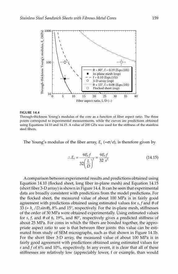
Stainless Steel Sandwich Sheets with Fibrous Metal Cores 159
The Young’s modulus of the fiber array, Ec (=s/e), is therefore given by
(14.15)
A comparison between experimental results and predictions obtained usingEquation 14.10 (flocked sheet, long fiber in-plane mesh) and Equation 14.15(short fiber 3-D array) is shown in Figure 14.4. It can be seen that experimentaldata are broadly consistent with predictions from the model predictions. Forthe flocked sheet, the measured value of about 100 MPa is in fairly goodagreement with predictions obtained using estimated values for s, f and q of33 (= hc /D.sinq), 8% and 15°, respectively. For the in-plane mesh, stiffnessesof the order of 30 MPa were obtained experimentally. Using estimated valuesfor s, f, and q of 6, 19%, and 80°, respectively gives a predicted stiffness ofabout 25 MPa. For cores in which the fibers are bonded together, the appro-priate aspect ratio to use is that between fiber joints: this value can be esti-mated from study of SEM micrographs, such as that shown in Figure 14.1b.For the short fiber 3-D array, the measured value of about 100 MPa is infairly good agreement with predictions obtained using estimated values fors and f of 6% and 10%, respectively. In any event, it is clear that all of thesestiffnesses are relatively low (appreciably lower, f or example, than would
FIGURE 14.4Through-thickness Young’s modulus of the core as a function of fiber aspect ratio. The threepoints correspond to experimental measurements, while the curves are predictions obtainedusing Equations 14.10 and 14.15. A value of 200 GPa was used for the stiffness of the stainlesssteel fibers.
10
100
1000
0 5 10 15 20 25 30 35 40
θ = 80°, f = 0.19 (Eqn.(10))In-plane mesh (exp)f = 0.10 (Eqn.(15))3-D array (exp)θ = 15°, f = 0.08 (Eqn.(10))Flocked sheet (exp)
Thro
ugh-
thic
knes
s You
ng’s
mod
ulus
, Ec (
MPa
)
Fiber aspect ratio, L/D (–)
∴ =⎛⎝⎜
⎞⎠⎟
=EE f
LD
E fs
cf f9
32
9322 2
IP155_C014.fm Page 159 Tuesday, January 8, 2008 11:21 AM
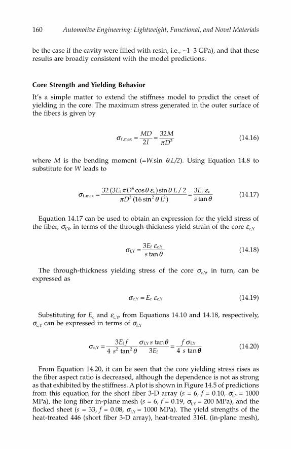
160 Automotive Engineering: Lightweight, Functional, and Novel Materials
be the case if the cavity were filled with resin, i.e., ~1–3 GPa), and that theseresults are broadly consistent with the model predictions.
Core Strength and Yielding Behavior
It’s a simple matter to extend the stiffness model to predict the onset ofyielding in the core. The maximum stress generated in the outer surface ofthe fibers is given by
(14.16)
where M is the bending moment (=W.sin q.L/2). Using Equation 14.8 tosubstitute for W leads to
(14.17)
Equation 14.17 can be used to obtain an expression for the yield stress ofthe fiber, sf,Y, in terms of the through-thickness yield strain of the core ec,Y
(14.18)
The through-thickness yielding stress of the core sc,Y, in turn, can beexpressed as
(14.19)
Substituting for Ec and ec,Y, from Equations 14.10 and 14.18, respectively,sc,Y can be expressed in terms of sf,Y
(14.20)
From Equation 14.20, it can be seen that the core yielding stress rises asthe fiber aspect ratio is decreased, although the dependence is not as strongas that exhibited by the stiffness. A plot is shown in Figure 14.5 of predictionsfrom this equation for the short fiber 3-D array (s = 6, f = 0.10, sf,Y = 1000MPa), the long fiber in-plane mesh (s = 6, f = 0.19, sf,Y = 200 MPa), and theflocked sheet (s = 33, f = 0.08, sf,Y = 1000 MPa). The yield strengths of theheat-treated 446 (short fiber 3-D array), heat-treated 316L (in-plane mesh),
σπf ,max = =MD
IM
D232
3
σ π θ ε θπf ,maxf c( cos ) sin /
( si= 32 3 2
16
4
3E D L
D nn ) tanf c
2 23
θεθL
Es
=
σ εθf,Y
c,Y=tanf3E
s
σ εc,Y c c,Y= E
σθ
σ θ σc,Y
f2
f,Y
f
f,Y
tantan
tan= =3
4 3 42E f
ssE
fs θθ
IP155_C014.fm Page 160 Tuesday, January 8, 2008 11:21 AM

Stainless Steel Sandwich Sheets with Fibrous Metal Cores 161
and the as-received (drawn) 316L (flocked sheet) fibers were obtained fromsingle fiber tensile testing (see Figure 14.6). Also plotted in Figure 14.5, isthe experimentally measured value of sc,Y, obtained from compression of theflocked sheet, which can be inferred from Figure 14.7 to be about 2.1 MPa.It can be seen that this value is in good agreement with the model predictions.
FIGURE 14.5Predicted dependence (Equation 14.20) of the through-thickness yield stress of the core on thefiber inclination angle. The yield strength of the fibers was obtained from the stress–straincurves of Figure 14.6. Also plotted is the experimental result for the yield stress of the flockedcore obtained from compression testing (Figure 14.7).
FIGURE 14.6Typical single fiber tensile testing data for (a) as-received (drawn) 316L (flocked sheet), (b) heat-treated 316L (long fiber in-plane mesh), and (c) heat-treated 446 (short fiber 3-D array) fibers.
0
1
2
3
4
5
6
0 10 20 30 40 50 60 70 80
s = 6, f = 0.10, σf,Y = 1000 MPas = 6, f = 0.19, σf,Y = 200 MPas=33, f = 0.08, σf,Y =1000 MPaFlocked sheet (exp)
Core
yiel
d st
ress
, σc,Y
(MPa
)
Fiber inclination angle, θ (°)
0
0.2
0.4
0.6
0.8
1
1.2
1.4
0 1 2 3 4 5 6 7 8
446 Heat-treated fiber316L As-received (drawn) fiber316L Heat-treated (drawn) fiber
Nom
inal
stre
ss (G
Pa)
Nominal strain (%)
∗
∗∗
IP155_C014.fm Page 161 Tuesday, January 8, 2008 11:21 AM
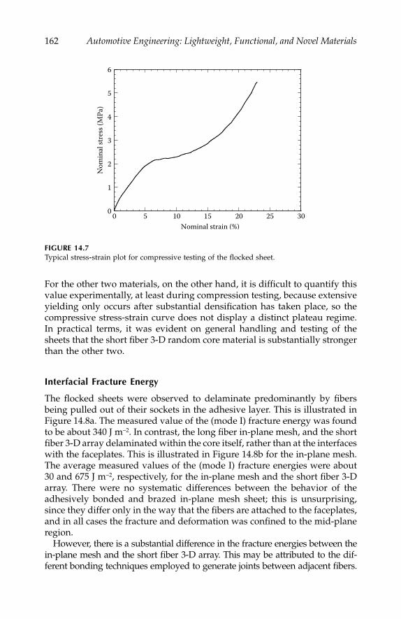
162 Automotive Engineering: Lightweight, Functional, and Novel Materials
For the other two materials, on the other hand, it is difficult to quantify thisvalue experimentally, at least during compression testing, because extensiveyielding only occurs after substantial densification has taken place, so thecompressive stress-strain curve does not display a distinct plateau regime.In practical terms, it was evident on general handling and testing of thesheets that the short fiber 3-D random core material is substantially strongerthan the other two.
Interfacial Fracture Energy
The flocked sheets were observed to delaminate predominantly by fibersbeing pulled out of their sockets in the adhesive layer. This is illustrated inFigure 14.8a. The measured value of the (mode I) fracture energy was foundto be about 340 J m−2. In contrast, the long fiber in-plane mesh, and the shortfiber 3-D array delaminated within the core itself, rather than at the interfaceswith the faceplates. This is illustrated in Figure 14.8b for the in-plane mesh.The average measured values of the (mode I) fracture energies were about30 and 675 J m−2, respectively, for the in-plane mesh and the short fiber 3-Darray. There were no systematic differences between the behavior of theadhesively bonded and brazed in-plane mesh sheet; this is unsurprising,since they differ only in the way that the fibers are attached to the faceplates,and in all cases the fracture and deformation was confined to the mid-planeregion.
However, there is a substantial difference in the fracture energies between thein-plane mesh and the short fiber 3-D array. This may be attributed to the dif-ferent bonding techniques employed to generate joints between adjacent fibers.
FIGURE 14.7Typical stress-strain plot for compressive testing of the flocked sheet.
0
1
2
3
4
5
6
0 5 10 15 20 25 30
Nom
inal
stre
ss (M
Pa)
Nominal strain (%)
IP155_C014.fm Page 162 Tuesday, January 8, 2008 11:21 AM
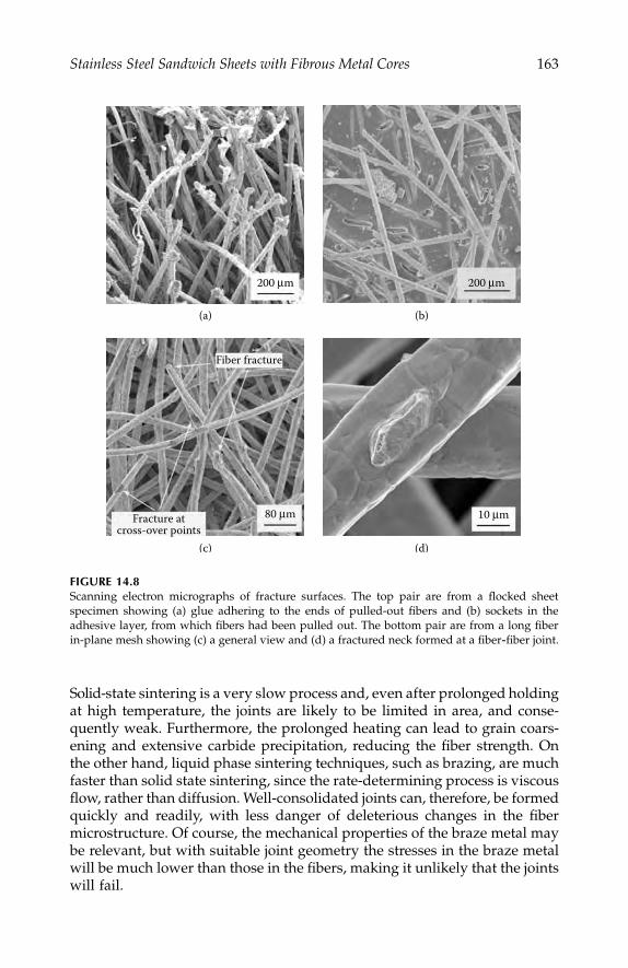
Stainless Steel Sandwich Sheets with Fibrous Metal Cores 163
Solid-state sintering is a very slow process and, even after prolonged holdingat high temperature, the joints are likely to be limited in area, and conse-quently weak. Furthermore, the prolonged heating can lead to grain coars-ening and extensive carbide precipitation, reducing the fiber strength. Onthe other hand, liquid phase sintering techniques, such as brazing, are muchfaster than solid state sintering, since the rate-determining process is viscousflow, rather than diffusion. Well-consolidated joints can, therefore, be formedquickly and readily, with less danger of deleterious changes in the fibermicrostructure. Of course, the mechanical properties of the braze metal maybe relevant, but with suitable joint geometry the stresses in the braze metalwill be much lower than those in the fibers, making it unlikely that the jointswill fail.
FIGURE 14.8Scanning electron micrographs of fracture surfaces. The top pair are from a flocked sheetspecimen showing (a) glue adhering to the ends of pulled-out fibers and (b) sockets in theadhesive layer, from which fibers had been pulled out. The bottom pair are from a long fiberin-plane mesh showing (c) a general view and (d) a fractured neck formed at a fiber-fiber joint.
(a) (b)
(c) (d)
200 μm 200 μm
10 μm80 μm
Fiber fracture
Fracture atcross-over points
IP155_C014.fm Page 163 Tuesday, January 8, 2008 11:21 AM
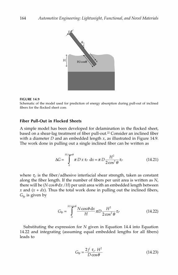
164 Automotive Engineering: Lightweight, Functional, and Novel Materials
Fiber Pull-Out in Flocked Sheets
A simple model has been developed for delamination in the flocked sheet,based on a shear-lag treatment of fiber pull-out.22 Consider an inclined fiberwith a diameter D and an embedded length x, as illustrated in Figure 14.9.The work done in pulling out a single inclined fiber can be written as
(14.21)
where ti* is the fiber/adhesive interfacial shear strength, taken as constantalong the fiber length. If the number of fibers per unit area is written as N,there will be (N cosq dx /H) per unit area with an embedded length betweenx and (x + dx). Thus the total work done in pulling out the inclined fibers,Gfp is given by
(14.22)
Substituting the expression for N given in Equation 14.4 into Equation14.22 and integrating (assuming equal embedded lengths for all fibers)leads to
(14.23)
FIGURE 14.9Schematic of the model used for prediction of energy absorption during pull-out of inclinedfibers for the flocked sheet core.
H H/cosθ
D
x
θ
ΔG D x x DH
H
= =∫ π τ πθ
τθ
cos
/cos
i* i*d0
2
22
GN x
HD
HH
fp i*d= ∫ cos
cos
/cosθ π
θτ
θ 2
2
02
Gf HDfp
i
cos= 2 2τ
θ*
IP155_C014.fm Page 164 Tuesday, January 8, 2008 11:21 AM
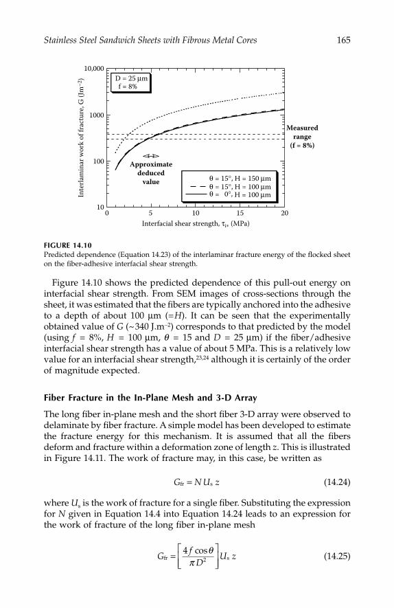
Stainless Steel Sandwich Sheets with Fibrous Metal Cores 165
Figure 14.10 shows the predicted dependence of this pull-out energy oninterfacial shear strength. From SEM images of cross-sections through thesheet, it was estimated that the fibers are typically anchored into the adhesiveto a depth of about 100 μm (=H). It can be seen that the experimentallyobtained value of G (~340 J.m−2) corresponds to that predicted by the model(using f = 8%, H = 100 μm, q = 15 and D = 25 μm) if the fiber/adhesiveinterfacial shear strength has a value of about 5 MPa. This is a relatively lowvalue for an interfacial shear strength,23,24 although it is certainly of the orderof magnitude expected.
Fiber Fracture in the In-Plane Mesh and 3-D Array
The long fiber in-plane mesh and the short fiber 3-D array were observed todelaminate by fiber fracture. A simple model has been developed to estimatethe fracture energy for this mechanism. It is assumed that all the fibersdeform and fracture within a deformation zone of length z. This is illustratedin Figure 14.11. The work of fracture may, in this case, be written as
(14.24)
where Us is the work of fracture for a single fiber. Substituting the expressionfor N given in Equation 14.4 into Equation 14.24 leads to an expression forthe work of fracture of the long fiber in-plane mesh
(14.25)
FIGURE 14.10Predicted dependence (Equation 14.23) of the interlaminar fracture energy of the flocked sheeton the fiber-adhesive interfacial shear strength.
10
100
1000
10,000
0 5 10 15 20
Inte
rlam
inar
wor
k of
frac
ture
, G (J
m–2
)
Interfacial shear strength, τi∗ (MPa)
Measuredrange
(f = 8%)
Approximatededuced
value
D = 25 μmf = 8%
θ = 15°, H = 150 μmθ = 15°, H = 100 μm
H = 100 μmθ = 0°,
G N U zfr s=
Gf
DU zfr s
cos=⎡
⎣⎢⎢
⎤
⎦⎥⎥
42
θπ
IP155_C014.fm Page 165 Tuesday, January 8, 2008 11:21 AM
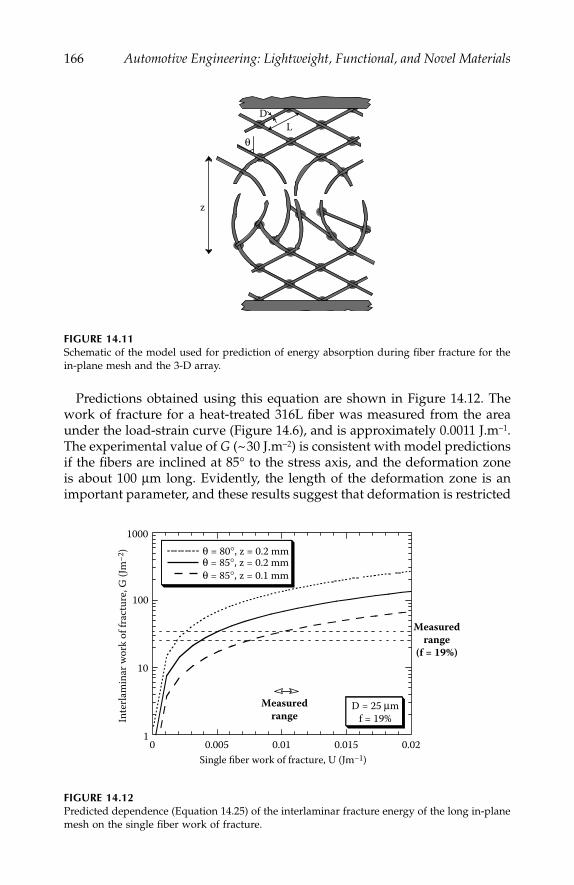
166 Automotive Engineering: Lightweight, Functional, and Novel Materials
Predictions obtained using this equation are shown in Figure 14.12. Thework of fracture for a heat-treated 316L fiber was measured from the areaunder the load-strain curve (Figure 14.6), and is approximately 0.0011 J.m−1.The experimental value of G (~30 J.m−2) is consistent with model predictionsif the fibers are inclined at 85° to the stress axis, and the deformation zoneis about 100 μm long. Evidently, the length of the deformation zone is animportant parameter, and these results suggest that deformation is restricted
FIGURE 14.11Schematic of the model used for prediction of energy absorption during fiber fracture for thein-plane mesh and the 3-D array.
FIGURE 14.12Predicted dependence (Equation 14.25) of the interlaminar fracture energy of the long in-planemesh on the single fiber work of fracture.
z
LD
θ
1
10
100
1000
0 0.005 0.01 0.015 0.02
Inte
rlam
inar
wor
k of
frac
ture
, G (J
m–2
)
Single fiber work of fracture, U (Jm–1)
Measuredrange
(f = 19%)
Measuredrange
D = 25 μmf = 19%
θ = 80°, z = 0.2 mmθ = 85°, z = 0.2 mmθ = 85°, z = 0.1 mm
IP155_C014.fm Page 166 Tuesday, January 8, 2008 11:21 AM
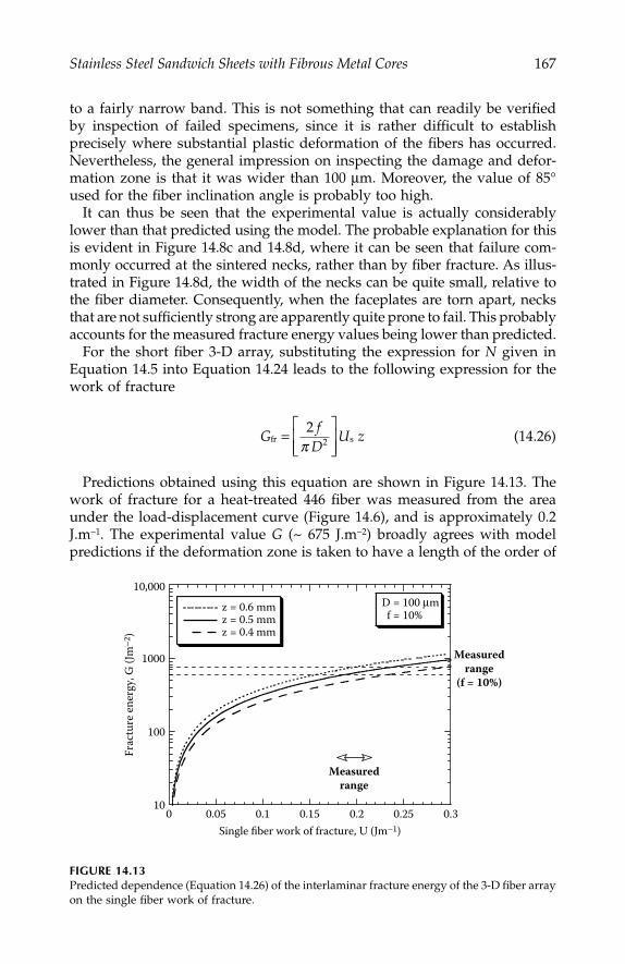
Stainless Steel Sandwich Sheets with Fibrous Metal Cores 167
to a fairly narrow band. This is not something that can readily be verifiedby inspection of failed specimens, since it is rather difficult to establishprecisely where substantial plastic deformation of the fibers has occurred.Nevertheless, the general impression on inspecting the damage and defor-mation zone is that it was wider than 100 μm. Moreover, the value of 85°used for the fiber inclination angle is probably too high.
It can thus be seen that the experimental value is actually considerablylower than that predicted using the model. The probable explanation for thisis evident in Figure 14.8c and 14.8d, where it can be seen that failure com-monly occurred at the sintered necks, rather than by fiber fracture. As illus-trated in Figure 14.8d, the width of the necks can be quite small, relative tothe fiber diameter. Consequently, when the faceplates are torn apart, necksthat are not sufficiently strong are apparently quite prone to fail. This probablyaccounts for the measured fracture energy values being lower than predicted.
For the short fiber 3-D array, substituting the expression for N given inEquation 14.5 into Equation 14.24 leads to the following expression for thework of fracture
(14.26)
Predictions obtained using this equation are shown in Figure 14.13. Thework of fracture for a heat-treated 446 fiber was measured from the areaunder the load-displacement curve (Figure 14.6), and is approximately 0.2J.m−1. The experimental value G (~ 675 J.m−2) broadly agrees with modelpredictions if the deformation zone is taken to have a length of the order of
FIGURE 14.13Predicted dependence (Equation 14.26) of the interlaminar fracture energy of the 3-D fiber arrayon the single fiber work of fracture.
Gf
DU zfr s=
⎡
⎣⎢⎢
⎤
⎦⎥⎥
22π
10
100
1000
10,000
0 0.05 0.1 0.15 0.2 0.25 0.3
z = 0.6 mmz = 0.5 mmz = 0.4 mm
Frac
ture
ener
gy, G
(Jm
–2)
Single fiber work of fracture, U (Jm–1)
Measuredrange
(f = 10%)
Measuredrange
D = 100 μmf = 10%
IP155_C014.fm Page 167 Tuesday, January 8, 2008 11:21 AM
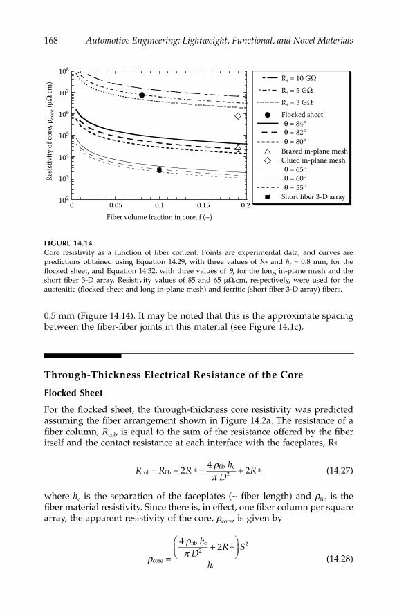
168 Automotive Engineering: Lightweight, Functional, and Novel Materials
0.5 mm (Figure 14.14). It may be noted that this is the approximate spacingbetween the fiber-fiber joints in this material (see Figure 14.1c).
Through-Thickness Electrical Resistance of the Core
Flocked Sheet
For the flocked sheet, the through-thickness core resistivity was predictedassuming the fiber arrangement shown in Figure 14.2a. The resistance of afiber column, Rcol, is equal to the sum of the resistance offered by the fiberitself and the contact resistance at each interface with the faceplates, R*
(14.27)
where hc is the separation of the faceplates (~ fiber length) and rfib is thefiber material resistivity. Since there is, in effect, one fiber column per squarearray, the apparent resistivity of the core, rcore, is given by
(14.28)
FIGURE 14.14Core resistivity as a function of fiber content. Points are experimental data, and curves arepredictions obtained using Equation 14.29, with three values of R* and hc = 0.8 mm, for theflocked sheet, and Equation 14.32, with three values of θ, for the long in-plane mesh and theshort fiber 3-D array. Resistivity values of 85 and 65 μΩ.cm, respectively, were used for theaustenitic (flocked sheet and long in-plane mesh) and ferritic (short fiber 3-D array) fibers.
102
103
104
105
106
107
108
0 0.05 0.1 0.15 0.2
R∗ = 10 GΩ
R∗ = 5 GΩ
R∗ = 3 GΩ
Flocked sheetθ = 84°θ = 82°θ = 80°
θ = 65°θ = 60°θ = 55°
Brazed in-plane meshGlued in-plane mesh
Short fiber 3-D array
Resis
tivity
of c
ore,
ρ cor
e (μΩ
cm)
Fiber volume fraction in core, f (–)
R R Rh
DRcol fib
fib c= + ∗ = + ∗24
22ρπ
ρ
ρπ
core
fib c
c=
+ ∗⎛⎝⎜
⎞⎠⎟
422
2hD
R S
h
IP155_C014.fm Page 168 Tuesday, January 8, 2008 11:21 AM
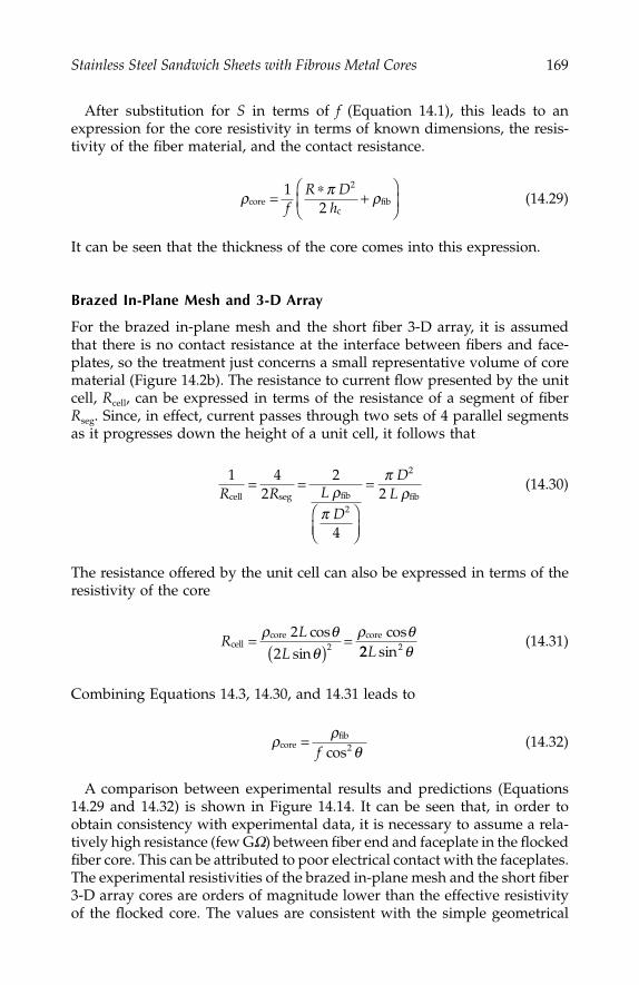
Stainless Steel Sandwich Sheets with Fibrous Metal Cores 169
After substitution for S in terms of f (Equation 14.1), this leads to anexpression for the core resistivity in terms of known dimensions, the resis-tivity of the fiber material, and the contact resistance.
(14.29)
It can be seen that the thickness of the core comes into this expression.
Brazed In-Plane Mesh and 3-D Array
For the brazed in-plane mesh and the short fiber 3-D array, it is assumedthat there is no contact resistance at the interface between fibers and face-plates, so the treatment just concerns a small representative volume of corematerial (Figure 14.2b). The resistance to current flow presented by the unitcell, Rcell, can be expressed in terms of the resistance of a segment of fiberRseg. Since, in effect, current passes through two sets of 4 parallel segmentsas it progresses down the height of a unit cell, it follows that
(14.30)
The resistance offered by the unit cell can also be expressed in terms of theresistivity of the core
(14.31)
Combining Equations 14.3, 14.30, and 14.31 leads to
(14.32)
A comparison between experimental results and predictions (Equations14.29 and 14.32) is shown in Figure 14.14. It can be seen that, in order toobtain consistency with experimental data, it is necessary to assume a rela-tively high resistance (few GW) between fiber end and faceplate in the flockedfiber core. This can be attributed to poor electrical contact with the faceplates.The experimental resistivities of the brazed in-plane mesh and the short fiber3-D array cores are orders of magnitude lower than the effective resistivityof the flocked core. The values are consistent with the simple geometrical
ρ π ρcorec
fib= ∗ +⎛
⎝⎜⎞
⎠⎟1
2
2
fR D
h
1 4cell seg fibR R L
D
D= =
⎛⎝⎜
⎞⎠⎟
=2
2
4
22
2
ρπ
πL ρfib
RL
Lcell
core core=( )
=cossin
cosρ θθ
ρ θ22 2 22 2L sin θ
ρ ρθcore
fib=cosf 2
IP155_C014.fm Page 169 Tuesday, January 8, 2008 11:21 AM

170 Automotive Engineering: Lightweight, Functional, and Novel Materials
model, assuming that the fibers are inclined at about 82 and 60, respectively,to the direction of current flow. These figures are at least approximatelycorrect. The resistance of the adhesively bonded in-plane mesh is consider-ably higher than the predicted levels for a brazed sintered mat, which isattributed to poor electrical contact with the faceplates. However, it can beseen that this is still better than in the flocked material. This is probablybecause pressure was applied while the adhesive was setting, bringing thefibers into better electrical contact with the faceplates than is possible withthe flocked sheet procedure.
Welding Characteristics
The flocked sheet could not be welded directly, since no significant currentflowed through the material with the electrode force and voltage used. Thisis consistent with the high measured electrical resistivity of the core. By usinga shunt, however, it was found to be possible to create a weld. Initially,sufficient current flowed through the faceplates and across the shunt to causeheating of the core between the electrodes, leading to softening, consolida-tion, and hence, sufficient reduction in core resistance to allow a substantialdirect current to flow and melting to occur. However, during these initialtrials, breakthrough of the core was inconsistent and the faceplates weresusceptible to local burn-through by the shunt current. In the example shownin Figure 14.15, breakthrough and current increase occurred only in the lastof the 10 cycles of weld time. Even then, the poor shape of the final halfcycles of current indicates intermittent current flow. In some cases, depend-ing on the position of the shunt, no breakthrough occurred at all.
FIGURE 14.15Voltage-time and current-time plots obtained during welding together of two flocked sheets,with a weld time of 10 cycles (0.2 s).
–10
–5
0
5
10
–8
–6
–4
–2
0
2
4
6
8
0 2 4 6 8 10
I
V
Curr
ent,
I (kA
)
Volta
ge, V
(V)
Time, t (cycles)
IP155_C014.fm Page 170 Tuesday, January 8, 2008 11:21 AM

Stainless Steel Sandwich Sheets with Fibrous Metal Cores 171
Even when a weld was created between flocked sheets, it was invariablyof poor quality. This can be seen in the micrograph shown in Figure 14.16,where it is clear that the pressure has resulted in much of the faceplatematerial being melted and squeezed out laterally. There has also been vapor-ization of the adhesive, leading to blow-holes, and cracking of the faceplates.Melt expulsion of this type is often problematic, particularly with thin metalsheets in composite materials, such as vibration damping steels.18 Such aweld would be mechanically very weak.
The brazed long fiber in-plane sheet, on the other hand, was readily weld-able. Figure 14.17 shows typical voltage and current plots. The current risesquickly to the set value and substantial heat is generated from the start inthe sheets between the electrodes. Sections through a corresponding weldare shown in Figure 14.18. It can be seen that the weld is of good quality,with some lateral flow of melted fibers, but the inner faceplates retaining
FIGURE 14.16Optical micrograph of a polished transverse section from a pair of flocked sheets after resistancewelding.
FIGURE 14.17Voltage-time and current-time plots obtained during welding together of two brazed in-planemesh sheets, with a weld time of 7 cycles (0.14 s).
0.3 mm
–10
–5
0
5
10
–4
–3
–2
–1
0
1
2
3
4
0 1 2 3 4 5 6 7 8
I
V
Curr
ent,
I (kA
)
Volta
ge, V
(V)
Time, t (cycles)
IP155_C014.fm Page 171 Tuesday, January 8, 2008 11:21 AM
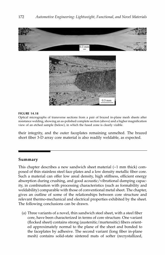
172 Automotive Engineering: Lightweight, Functional, and Novel Materials
their integrity, and the outer faceplates remaining unmelted. The brazedshort fiber 3-D array core material is also readily weldable, as expected.
Summary
This chapter describes a new sandwich sheet material (~1 mm thick) com-posed of thin stainless steel face plates and a low density metallic fiber core.Such a material can offer low areal density, high stiffness, efficient energyabsorption during crushing, and good acoustic/vibrational damping capac-ity, in combination with processing characteristics (such as formability andweldability) comparable with those of conventional metal sheet. The chapter,gives an outline of some of the relationships between core structure andrelevant thermo-mechanical and electrical properties exhibited by the sheet.The following conclusions can be drawn.
(a) Three variants of a novel, thin sandwich steel sheet, with a steel fibercore, have been characterized in terms of core structure. One variant(flocked sheet) contains strong (austenitic/martensitic) fibers orient-ed approximately normal to the plane of the sheet and bonded tothe faceplates by adhesive. The second variant (long fiber in-planemesh) contains solid-state sintered mats of softer (recrystallized,
FIGURE 14.18Optical micrographs of transverse sections from a pair of brazed in-plane mesh sheets afterresistance welding, showing an as-polished complete section (above) and a higher magnificationview of an etched sample (below), in which the fused zone is clearly visible.
0.3 mm
0.3 mm
IP155_C014.fm Page 172 Tuesday, January 8, 2008 11:21 AM

Stainless Steel Sandwich Sheets with Fibrous Metal Cores 173
fully austenitic) fibers oriented at low angles to the plane of the sheet,brazed or adhesively bonded to the faceplates. The third variant(short fiber 3-D array) contains an approximately 3-D random net-work of strong, melt-spun (ferritic) fibers, brazed to each other andto the faceplates. Fiber contents in the core are around 10% for theflocked sheet and the 3-D array, while the figure is about twice thisfor the in-plane mesh.
(b) The measured through-thickness Young’s moduli are relatively low(~10–100 MPa) and are broadly consistent with predictions from ananalytical model based on the bending of individual fibers. Core yieldstress values have also been explored, and are in the range 1–10 MPa.In this context, it is worth noting that, in sandwich sheets, the bend-ing stiffness and strength are dominated by the faceplates, so thecore does not necessarily need to be very stiff or strong. However,very compliant, or very soft, cores might be problematic, in that theymay allow excessive shear between the faceplates or failure to main-tain faceplate separation under load, leading to low beam stiffnessor premature plastic deformation of the sheet. The brazed 3-Drandom fiber array core performs appreciably better than the othertwo in this regard.
(c) The fracture energy during delamination of the faceplates has beenmeasured for mode I loading conditions. The flocked fiber core fails bypull-out of fibers from their sockets in the adhesive. A model has beendeveloped to predict the energy absorbed during fiber pull-out, basedon simple shear lag theory. Good agreement is found between theoryand experiment, assuming an interfacial shear strength between fiberand adhesive of about 5 MPa. The long in-plane mesh and the shortfiber 3-D array both fail by fracture within the core. A model has beendeveloped for prediction of the fracture energy for this type of failure,based on deformation and fracture of individual fibers. Good agree-ment with experiment is obtained for the short fiber 3-D array sheet,which has the highest fracture energy. Experimental values for the longfiber in-plane mesh, however, are lower than predicted. This is ascribedto a tendency for delamination to occur by failure of solid-state sinteredfiber-fiber necks, which are relatively weak, rather than by fiber fracture.
(d) Through-thickness electrical resistivities have been measured for thecores of the flocked sheet (~10 W.cm), adhesively bonded in-plane mesh(~1 W.cm), brazed long in-plane mesh (~0.01 W.cm), and the brazedshort fiber 3-D array (~0.001 W.cm). These values compare well withpredictions from simple geometrical models. The high resistivity ofthe flocked fiber core is attributed to poor electrical contact betweenthe fiber ends and the faceplates.
(e) The flocked (adhesively bonded) material could not readily be weld-ed. A shunt was required to achieve any melting, but electricalcontact through the core was variable. In addition, weld flaws and
IP155_C014.fm Page 173 Tuesday, January 8, 2008 11:21 AM

174 Automotive Engineering: Lightweight, Functional, and Novel Materials
faceplate damage occurred during welding. The brazed long fiberin-plane mesh material, on the other hand, exhibited good weldingcharacteristics, with good current flow from the start of the weldingperiod. The short fiber 3-D array sheet is also readily weldable.
(f) Overall, it is clear that sheet of this type can offer attractive combi-nations of lightweight, high beam stiffness/strength, good interfacialtoughness, and low through-thickness electrical resistivity—allowingresistance welding to be carried out easily with conventional equip-ment. Of the three cores examined, the brazed short fiber 3-D arraystructure clearly offers the best combination of these properties. On-going work is aimed at exploring the influence of core structure onother aspects of sheet performance, including fatigue resistance,formability, energy absorption during crushing, and sound/vibrationdamping characteristics, as well as optimization of sheet manufac-turing procedures. The material is evidently of potential interest tothe automotive industry, even though it will inevitably be somewhatmore expensive than monolithic metal sheet.
References
1. McCormack, T. M., R. Miller, O. Kesler, and L. J. Gibson, “Failure of SandwichBeams with Metallic Foam Cores,” Int. J. of Solids and Structures, Vol. 38 (28–29),4901–4920, 2001.
2. Chen, C., A. M. Harte, and N. A. Fleck, “The Plastic Collapse of SandwichBeams with a Metallic Foam Core,” Int. J. Mech. Sci., Vl. 43, No. 6, 1483–1506,2001.
3. Harte, A. M., N. A. Fleck, and M. F. Ashby, “Sandwich Panel Design usingAluminum Alloy Foam,” Adv. Engng. Mater., vol. 2, No. 4, 219–222, 2000.
4. Lok, T. S., and Q. H. Chen, “Elastic Stiffness Properties and Behavior of Truss-Core Sandwich Panel,” J. Structural Engineering—ASCE, Vol. 126, No. 5,552–559, 2000.
5. Sypeck, D. J., and H. N. G. Wadley, “Multifunctional Microtruss Laminates:Textile Synthesis and Properties,” J. Mater. Res., Vol. 16, No. 3, 890–897, 2001.
6. Chiras, S., D. R. Mumm, A. G. Evans, N. Wicks, J. W. Hutchinson, K. Dharmasena,H. N. G. Wadley, and S. Fichter, “The Structural Performance of Near-OptimizedTruss Core Panels,” Int. J. of Solids and Structures, Vol. 39, No. 15, 4093–4115, 2002.
7. Gustavsson, R., “Formable Sandwich Construction Material and Use of theMaterial as Construction Material in Vehicles, Refrigerators, Boats etc.,” patentWO 98/01295, 15th Jan., 1998, AB Volvo, International.
8. Markaki, A. E., and T. W. Clyne, “Mechanics of Thin Ultra-Light Stainless SteelSandwich Sheet Material: Part I—Stiffness,” Acta Mater., Vol. 51, No. 5,1341–1350, 2003.
9. Markaki, A. E., and T. W. Clyne, “Mechanics of Thin Ultra-Light Stainless SteelSandwich Sheet Material: Part II—Resistance to Delamination,” Acta Mater.,Vol. 51, No. 5, 1351–1357, 2003.
IP155_C014.fm Page 174 Tuesday, January 8, 2008 11:21 AM

Stainless Steel Sandwich Sheets with Fibrous Metal Cores 175
10. Jou, M., “Experimental investigation of resistance spot welding for sheet metalsused in automotive industry,” JSME Int. J. Series C-Mech. Systems, MachineElements, and Manufacturing, Vol. 44, no. 2, 544–552, 2001.
11. Babu, S. S., M. L. Santella, Z. Feng, B. W. Riemer, and J. W. Cohron, “EmpiricalModel of Effects of Pressure and Temperature on Electrical Contact Resistance ofMetals,” Science and Technology of Welding and Joining, Vol. 6, no. 3, 126–132, 2001.
12. Wang, S. C., and P. S. Wei, “Modeling Dynamic Electrical Resistance duringResistance Spot Welding,” J. Heat Transfer-Trans.—ASME, Vol. 123, No. 3,576–585, 2001.
13. Khan, J. A., L. J. Xu, Y. J. Chao, and K. Broach, “Numerical Simulation ofResistance Spot Welding Process,” Numerical Heat Transfer Part A—-Applications,Vol. 37, No. 5, 425–446, 2000.
14. Dilthey, U., H. C. Bohlmann, U. Reisgen, W. Sudnik, W. Erofeew, and R. Kudinow,“Modelling and Numerical Simulation of Resistance Spot Welding with Experi-mental Verification,” 9th International Conference on the Joining of Materials,Helsingor, Denmark, 38–43, 1999.
15. Tang, H., W. Hou, S. J. Hu, and H. Zhang, “Force Characteristics of ResistanceSpot Welding of Steels,” Welding Journal, Vol. 79, No. 7, 175S–183S, 2000.
16. Zhou, Y., P. Gorman, W. Tan, and K. J. Ely, “Weldability of Thin Sheet Metalsduring Small-Scale Resistance Spot Welding using an Alternating-CurrentPower Supply,” J. Electronic Materials, Vol. 29, No. 9, 1090–1099, 2000.
17. Markaki, A. E., S. A. Westgate, and T. W. Clyne, “The Stiffness and Weldabilityof an Ultra-Light Steel Sandwich Sheet Material with a Fibrous Metal Core,”Processing and Properties of Lightweight Cellular Metals and Structures, Seattle, eds.A. K. Ghosh, T. D. Claar, and T. H. Sanders, TMS, 15–24, 2002.
18. Oberle, H., C. Commaret, R. Magnaud, C. Minier, and G. Pradere, “OptimizingResistance Spot Welding Parameters for Vibration Damping Steel Sheets,”Welding Journal, Vol. 77, No. 1, 8S–13S, 1998.
19. Sorensen, B. F., A. Horsewell, O. Jorgensen, and A. N. Kumar, “Fracture Resis-tance Measurement Method for in situ Observation of Crack Mechanisms,”J. Am. Ceram. Soc., vol. 81, no. 3, 661–669, 1998.
20. Whitehouse, A. F., C. M. Warwick, and T. W. Clyne, “The Electrical Resistivityof Copper Reinforced with Short Carbon Fibers,” J. Mat. Sci., Vol. 26, 6176–6182,1991.
21. Underwood, E. E., Quantitative Stereology, Reading: Addison–Wesley Publish-ing Company, 1970.
22. Hull, D., and T. W. Clyne, An Introduction to Composite Materials, CambridgeSolid State Science Series, ed., D. R. Clarke, S. Suresh, and I. M. Ward, Cam-bridge: Cambridge University Press, 1996.
23. DiFrancia, C., T. C. Ward, and R. O. Claus, “The Single-fiber Pull-out Test 1:Review and Interpretation,” Composites A, Vol. 27, 597–612, 1996.
24. Kim, J. K., C. Baillie, and Y. W. Mai, “Interfacial Debonding and Fiber Pull-outStresses, Part I—Critical Comparison of Existing Theories with Experiments,”J. Mat. Sci., Vol. 27, 3143–3154, 1992.
IP155_C014.fm Page 175 Tuesday, January 8, 2008 11:21 AM

IP155_C014.fm Page 176 Tuesday, January 8, 2008 11:21 AM

Section 4
Processing and Manufacturing
The cost-effective scaling-up of new processes and new manufacturing tech-niques for the mass production of automobiles is a huge technological andeconomic challenge. The supply chain in the mass production automotivesector is notoriously competitive and production margins are often small.Even in niche automotive manufacture, there are significant constraints anddownward pressure on costs, so that new materials and their associatedfabrication and assembly procedures must offer demonstrable economic ben-efit. In recent years in some automotive segments, cost of ownership andespecially fuel costs, have increased in importance and are beginning to favorthe adoption of some new manufacturing processes—for example the hydro-formed Al alloy sub-chassis—allowing more durable, more cost-effectiveand low life-cost materials to be used. This section discusses the drivers andopportunities for new processes and manufacturing technology including:
• Welding and joining• Titanium alloys in harsh environments• Casting• Durable and high-performance composites• Surface treatments in autosport
IP155_S004.fm Page 1 Monday, December 10, 2007 4:15 PM

IP155_S004.fm Page 2 Monday, December 10, 2007 4:15 PM

179
15
Welding and Joining
J. G. Wylde and J. M. Kell
CONTENTS
Introduction .........................................................................................................179Friction Stir Welding ..........................................................................................180Clearweld™ .........................................................................................................186AdhFAST™ ..........................................................................................................189Laser Welding of High-Strength Steels ...........................................................193Conclusions..........................................................................................................194References.............................................................................................................195
Introduction
Within the automotive sector there is a continual drive toward reducingcosts, improving performance, and increasing sustainability. Inevitably, thisleads to the search for new materials and structures that will offer improvedperformance and reduce cost. These efforts have resulted in developmentsand advances in materials across a spectrum of materials including metals,plastics, ceramics, and composites.
However, all too often, one vital ingredient is ignored. This is the simplequestion, how will these materials be joined? Thus, with few exceptions,new materials can only be effectively used in engineering structures if theycan be joined to themselves, and in many cases, to other materials. Thesejoins must be capable of being made cheaply and reliably in a mass produc-tion environment, and furthermore, the properties of the joints must besufficient to avoid premature failure in service.
Consequently, materials joining technology is one of the key enablingtechnologies in almost every branch of manufacturing, and the automotivesector is no exception. Thus, automotive engineers are keenly interested in
IP155_C015.fm Page 179 Monday, December 31, 2007 5:02 PM
180
Automotive Engineering: Lightweight, Functional, and Novel Materials
developments in joining technologies. Reducing the cost of manufacturingcan have a major impact on price. Increasing the strength and integrity ofjoints can have a major impact on design, and offer the potential for reducingmaterial thickness, and thus, reducing weight.
Dozens of different joining technologies are used in the manufacture ofautomotive components and structures. This chapter covers some of therecent developments in joining technology that provide opportunities forimproved use of advanced materials, and improved aesthetic appearanceand design.
Friction Stir Welding
In recent years, there has been an increasing interest in the use of lightweightmaterials in automotive fabrication. Aluminum alloys offer considerablepotential for weight reduction because of their high strength-to-weight ratio.However, they are not generally as readily weldable, particularly in a massproduction environment, as many steels. For this reason, friction stir welding(FSW) has gained increasing interest since its invention some ten years ago.Friction stir welding is a novel joining process developed at TWI in 1991.
1
Engineers have long recognized that frictional heating could be used to joinmaterials. Conventionally, one round or tubular component is rotated, andpushed against another. The frictional heating that takes place causes bothcomponents to become hot, and one or both to become plasticized. Theapplication of a forging force to push the components together can then beused to form a solid state or friction weld. Such welds have consistentlybeen shown to possess exceptional mechanical properties.
During the past thirty years or so, a number of developments of the frictionwelding process have been made to allow the process to be applied to awider range of geometries and shapes. Orbital and linear friction weldingenabled the process to be applied to a variety of non-round components.However, virtually all of these techniques involve relative motion betweenparts to generate the frictional heating. This naturally limits the applicationof friction welding to relatively modest sections and components, which canbe held within a machine and moved relative to each other to develop thefrictional heating. Furthermore, they involve the joining process taking placeat, more or less, the same time across the entire joint area. Thus, as the size orlength of the component grows, so the forces involved in the application ofthe process also increase dramatically.
In the 1980s, Thomas
2
developed other variants of frictional heating of mate-rials and showed that friction could also be used to extrude metals—frictionextrusion. It was from this development and the desire to extend frictiontechniques to larger parts, that friction stir welding was born. Thomas et al.
3
discovered that butt-welded seams could be produced using a rotating tool
IP155_C015.fm Page 180 Monday, December 31, 2007 5:02 PM

Welding and Joining
181
with a shoulder and pin. The design of the tool is key to the successfulapplication of the process, and a number of different designs have beeninvestigated. Essentially, the height of the pin is the same as the thicknessof the material to be joined. The pin is pushed into the seam until theshoulder comes into contact with the top surface of the material. After a briefdwell period, the tool is then moved along the length of the seam.
As the tool moves through the material, some material is taken from theedges of the parts being joined, mixed, and transported to the back of the pinwhere it extrudes into the area behind the pin to form a solid phase bond.This concept is illustrated in Figure 15.1. Being a friction process, there isno melting of the material, thus the weld produced is a solid phase joint.Consequently, there is no fume and no associated loss of alloying elements.There is no porosity, as there has been no solidification from moltenmaterial.
Figure 15.2 shows a transverse section through a typical friction stirweld. Threadgill
4
has characterized the various regions of the weld asindicated in the figure. The weld “nugget” shows a fully recrystallizedmaterial with a fine grain structure. Next to the nugget lies a zone ofmaterial that has been subject to considerable mechanical and thermaleffects, the thermomechanically affected zone. Here, the original structurehas been distorted by the mechanical motion of the tool. Some recrystal-lization has taken place and the material has been subjected to a thermalcycle. Adjacent to this, is a thermally affected region that forms a transitionto base material.
FIGURE 15.1
Principle of FSW.
Tool shoulder
Backing bar
Profiled pin
Work piece
a
bc
d
Unaffected materialHeat affected zone (HAZ)Thermomechanicallyaffected zone (TMAZ)Weld nugget (Part of thermomechanically affected zone)
a b
ab
ccd
IP155_C015.fm Page 181 Monday, December 31, 2007 5:02 PM
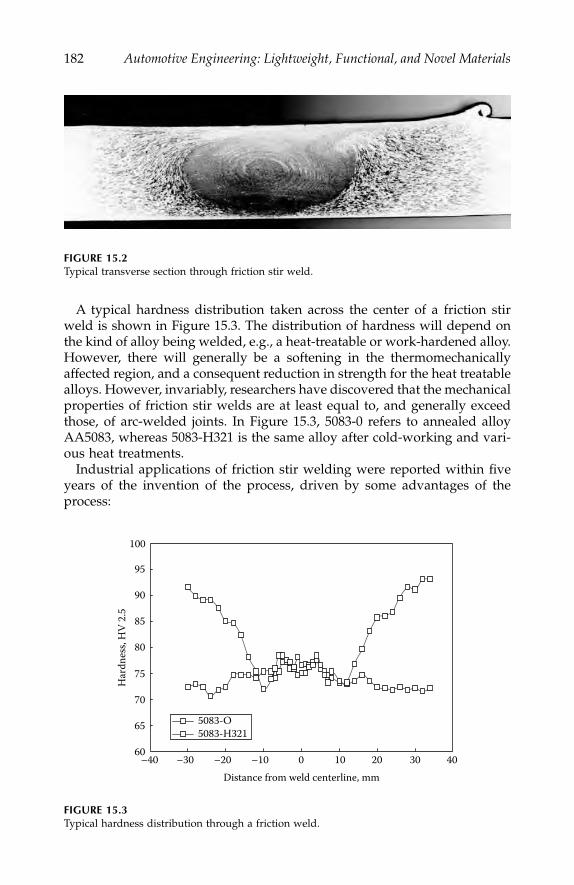
182
Automotive Engineering: Lightweight, Functional, and Novel Materials
A typical hardness distribution taken across the center of a friction stirweld is shown in Figure 15.3. The distribution of hardness will depend onthe kind of alloy being welded, e.g., a heat-treatable or work-hardened alloy.However, there will generally be a softening in the thermomechanicallyaffected region, and a consequent reduction in strength for the heat treatablealloys. However, invariably, researchers have discovered that the mechanicalproperties of friction stir welds are at least equal to, and generally exceedthose, of arc-welded joints. In Figure 15.3, 5083-0 refers to annealed alloyAA5083, whereas 5083-H321 is the same alloy after cold-working and vari-ous heat treatments.
Industrial applications of friction stir welding were reported within fiveyears of the invention of the process, driven by some advantages of theprocess:
FIGURE 15.2
Typical transverse section through friction stir weld.
FIGURE 15.3
Typical hardness distribution through a friction weld.
60
65
70
75
80
85
90
95
100
–40 –30 –20 –10 0 10 20 30 40Distance from weld centerline, mm
Har
dnes
s, H
V 2.
5
5083-O5083-H321
IP155_C015.fm Page 182 Monday, December 31, 2007 5:02 PM
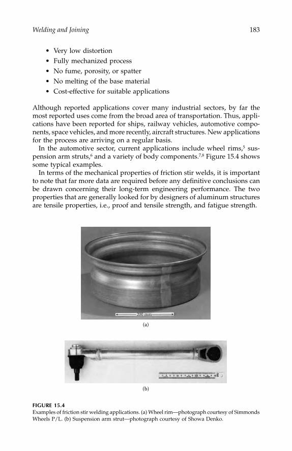
Welding and Joining
183
• Very low distortion• Fully mechanized process• No fume, porosity, or spatter• No melting of the base material• Cost-effective for suitable applications
Although reported applications cover many industrial sectors, by far themost reported uses come from the broad area of transportation. Thus, appli-cations have been reported for ships, railway vehicles, automotive compo-nents, space vehicles, and more recently, aircraft structures. New applicationsfor the process are arriving on a regular basis.
In the automotive sector, current applications include wheel rims,
5
sus-pension arm struts,
6
and a variety of body components.
7,8
Figure 15.4 showssome typical examples.
In terms of the mechanical properties of friction stir welds, it is importantto note that far more data are required before any definitive conclusions canbe drawn concerning their long-term engineering performance. The twoproperties that are generally looked for by designers of aluminum structuresare tensile properties, i.e., proof and tensile strength, and fatigue strength.
FIGURE 15.4
Examples of friction stir welding applications. (a) Wheel rim—photograph courtesy of SimmondsWheels P/L. (b) Suspension arm strut—photograph courtesy of Showa Denko.
200 mm
(a)
(b)
IP155_C015.fm Page 183 Monday, December 31, 2007 5:02 PM

184
Automotive Engineering: Lightweight, Functional, and Novel Materials
In terms of tensile strength, various researchers have carried out 180º faceand root bend tests, and cross-weld tensile tests. The bend test is a usefulguide to weld quality and ductility, and provided friction stir welds are madeunder optimum conditions, the bend test is invariably passed without evi-dence of cracking. In terms of the cross-weld tensile tests, many comparisonshave been made with base material properties and with other welding meth-ods. The results vary according to the type of alloy being tested, but aregenerally very encouraging.
In terms of fatigue performance, friction stir welds demonstrate goodproperties. In general terms, welded joints possess a much lower fatiguestrength than that of the base material. There is a combination of reasons forthis including the presence of sharp discontinuities on a microscopic scale atthe edge of the weld, a stress concentration caused by the weld shape, andthe presence of tensile residual stresses. This phenomenon is well understoodby designers, and various sets of fatigue design curves have been developedfor arc-welded joints. Thus, the design stress for a conventional-welded jointcan be determined by establishing the appropriate joint classification anddetermining the design stress according to the required fatigue life.
Remarkably, fatigue tests on friction stir welds have indicated that theycan possess a higher fatigue strength than arc welds. In some cases thereseems to be very little difference between the fatigue performance of thefriction stir weld and that of the base material. The reasons for this are notfully understood, and more tests are required to verify this conclusion.Preliminary results suggest that the design stress for a friction stir weld mightbe some 50% higher than that for an arc weld. Clearly, if this increase isconfirmed with additional data, it will have very significant consequencesfor designers of automotive structures.
In general, in fatigue-sensitive structures it is the fatigue strength of thewelds that determines the design stresses, and hence, the material thick-nesses. If it is confirmed that a higher design stress can be used for frictionstir welding, then this may result in some structures being fabricated fromthinner section materials, and this could have major significance for theautomotive industry where the use of thinner materials will reduce weight,increase performance characteristics, and improve fuel economy. Conse-quently, it is not surprising that many designers and fabricators are investi-gating the potential for friction stir welding.
The vast majority of research on friction stir welding, and virtually all theproduction applications of the process to date, relate to aluminum alloys.However, the process has also been shown to be applicable to a range ofother materials, including magnesium, copper, and zinc. It has also beenshown to be feasible for steels, but further work is required before it can beconsidered as a production process for joining steels.
One final and particularly interesting feature of friction stir welding is itsability to make joints between some dissimilar materials. For example, jointsbetween different aluminum alloys are feasible, as are joints between castand wrought aluminum alloys. This flexibility is particularly relevant to the
IP155_C015.fm Page 184 Monday, December 31, 2007 5:02 PM

Welding and Joining
185
automotive sector, where there is an increasing interest in the use of castcomponents. Figure 15.5 shows an example of a friction stir weld betweencast and wrought aluminum alloys.
Friction stir welding has also been used with some success to join com-pletely dissimilar materials, e.g., aluminum and magnesium alloys. This isparticularly relevant to the automotive sector as there is increasing interestin the use of magnesium to reduce weight. Figure 15.6 shows a joint betweenaluminum alloy 2219 and magnesium alloy AZ 91.
FIGURE 15.5
Wrought aluminum welded to cast aluminum alloy.
FIGURE 15.6
Friction stir weld between aluminum and magnesium alloys.
IP155_C015.fm Page 185 Monday, December 31, 2007 5:02 PM

186
Automotive Engineering: Lightweight, Functional, and Novel Materials
Clearweld™
Plastic materials are increasingly used in automotive components. TWI in con-junction with Gentex Corporation have developed a technique for laser weld-ing plastics with an infrared absorbing material, creating a joint that is almostinvisible to the human eye. Typically, carbon black would be used as the absorb-ing medium for the laser light; although the new approach enables two similarclear (or colored) plastics to be joined, with a minimal marking at weld line.
The development of the laser as an industrial heat source has resulted ina range of applications that utilize the precise, controllable energy it delivers.Early developments in welding plastics with lasers showed that thin filmscould be joined.
9
However, at that time, CO
2
lasers were the principle powersource. The nature of the interaction between the 10.6
μ
m wavelength beamfrom the CO
2
laser and thermoplastic materials meant an analogue to thedeep-penetration process used to weld metals could not be developed. TheCO
2
laser beam is absorbed at the surface of the plastic, relying on conductionof heat through the thickness of the material, which results in decomposition,vaporization, and charring, before any significant depth of material ismelted. Nonetheless, thin polyolefin films, of the order 0.1 mm thick, havebeen successfully welded with a CO
2
laser at speeds up to 500 m/min.
10
The increasing use of Nd:YAG solid-state lasers, and the advent of diodelasers (both producing beams with a near infrared wavelength), has madeavailable lasers with different beam/material interaction characteristics withthermoplastics. In transmission welding, the laser beam passes through thetop (transmitting) layer and is absorbed by the filler in the lower layer,producing sufficient heat to make a weld at the interface between the twoparts. This process was first described for welding automotive componentsin 1985.
11
An example of the transmission-welding technique, utilizing avisually transmissive plastic material for the upper section and a carbonblack loaded plastic for the lower layer, can be seen in Figure 15.7.
FIGURE 15.7
Laser transmission weld in 4 mm thick polypropylene using a 100W Nd:YAG laser at a speedof 1.6 m/min. The weld is at the interface between the light and dark materials.
IP155_C015.fm Page 186 Monday, December 31, 2007 5:02 PM
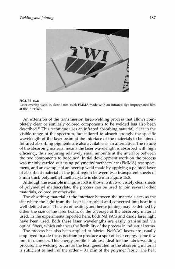
Welding and Joining
187
An extension of the transmission laser-welding process that allows com-pletely clear or similarly colored components to be welded has also beendescribed.
12
This technique uses an infrared absorbing material, clear in thevisible range of the spectrum, but tailored to absorb strongly the specificwavelength of the laser beam at the interface of the materials to be joined.Infrared absorbing pigments are also available as an alternative.
The natureof the absorbing material means the laser wavelength is absorbed with highefficiency, thus requiring relatively small amounts at the interface betweenthe two components to be joined. Initial development work on the processwas mainly carried out using polymethylmethacrylate (PMMA) test speci-mens, and an example of an overlap weld made by applying a painted layerof absorbent material at the joint region between two transparent sheets of3 mm thick polymethyl methacrylate is shown in Figure 15.8.
Although the example in Figure 15.8 is shown with two visibly clear sheetsof polymethyl methacrylate, the process can be used to join several othermaterials, colored or otherwise.
The absorbing material at the interface between the materials acts as thesite where the light from the laser is absorbed and converted into heat in awell-defined area. The area of heating, and hence joining, may be defined byeither the size of the laser beam, or the coverage of the absorbing materialused. In the experiments reported here, both Nd:YAG and diode laser lighthave been used. Both these laser wavelengths are easily transmitted viaoptical fibers, which enhances the flexibility of the process in industrial terms.
The process has also been applied to fabrics. Nd:YAG lasers are usuallyemployed in a de-focus position to produce a spot of laser energy some fewmm in diameter. This energy profile is almost ideal for the fabric-weldingprocess. The welding occurs as the heat generated in the absorbing materialis sufficient to melt, of the order
≈
0.1 mm of the polymer fabric. The heat
FIGURE 15.8
Laser overlap weld in clear 3 mm thick PMMA made with an infrared dye impregnated filmat the interface.
IP155_C015.fm Page 187 Monday, December 31, 2007 5:02 PM
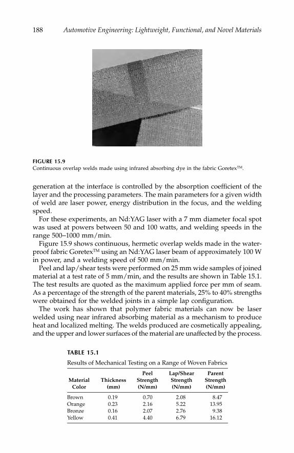
188
Automotive Engineering: Lightweight, Functional, and Novel Materials
generation at the interface is controlled by the absorption coefficient of thelayer and the processing parameters. The main parameters for a given widthof weld are laser power, energy distribution in the focus, and the weldingspeed.
For these experiments, an Nd:YAG laser with a 7 mm diameter focal spotwas used at powers between 50 and 100 watts, and welding speeds in therange 500
–
1000 mm/min.Figure 15.9 shows continuous, hermetic overlap welds made in the water-
proof fabric Goretex
TM
using an Nd:YAG laser beam of approximately 100 Win power, and a welding speed of 500 mm/min.
Peel and lap/shear tests were performed on 25 mm wide samples of joinedmaterial at a test rate of 5 mm/min, and the results are shown in Table 15.1.The test results are quoted as the maximum applied force per mm of seam.As a percentage of the strength of the parent materials, 25% to 40% strengthswere obtained for the welded joints in a simple lap configuration.
The work has shown that polymer fabric materials can now be laserwelded using near infrared absorbing material as a mechanism to produceheat and localized melting. The welds produced are cosmetically appealing,and the upper and lower surfaces of the material are unaffected by the process.
FIGURE 15.9
Continuous overlap welds made using infrared absorbing dye in the fabric Goretex
TM
.
TABLE 15.1
Results of Mechanical Testing on a Range of Woven Fabrics
MaterialColor
Thickness(mm)
PeelStrength(N/mm)
Lap/ShearStrength(N/mm)
ParentStrength(N/mm)
Brown 0.19 0.70 2.08 8.47Orange 0.23 2.16 5.22 13.95Bronze 0.16 2.07 2.76 9.38Yellow 0.41 4.40 6.79 16.12
IP155_C015.fm Page 188 Monday, December 31, 2007 5:02 PM

Welding and Joining
189
In mechanical testing, joint strengths of between 20% and 40% of the parentmaterial strength have been achieved in a simple lap joint. The weldingprocess is efficiently achieved using compact diode laser sources now avail-able commercially, and lends itself easily to high levels of automation.
The process of laser welding using an infrared absorbing material has beengiven the trademark ClearWeld
TM
. In addition, patent protection has beeninitiated by TWI on this process. Gentex Corporation is licensed by TWI toexploit the ClearWeld
TM
technique.
AdhFAST™
Despite widespread skepticism, adhesives are playing an increasingly impor-tant role throughout the engineering world, and will continue to find newapplications in volume applications. The primary drivers behind the growthin the use of adhesives are the increasing interest in combining differentmaterials in structures to maximize performance, e.g., plastics, metals, ceram-ics, composites, etc., and the advantages adhesives offer over traditionalpoint joining techniques. These advantages can be broadly defined as:
• Ability to join almost any material combination.• Superior fatigue properties.• Elimination/reduction of stress concentration points by bonding
the whole joint area.• Ability to have mechanical properties tailored to joint function, i.e.,
rigidity, elasticity, toughness, coefficient of thermal expansion, etc.• Ability to have physical properties tailored to requirements, i.e.,
electrical and thermal conduction/insulation, and cure initiated byradiation (blue or UV light, electron beams).
• Sealing ability.• Elimination/minimization of thermal distortion.
However, despite these advantages, some engineers are concerned about theuse of adhesives because of the perception that they are:
• A poor or weaker substitute for welding or mechanical fasteners.• Messy to use.• Perceived to have significant health and safety risks.• Difficult to inspect and to assess the significance of any defects.• In need of complex pre- and post-processing.
It is well established that adhesives can fulfill a structural function bothreliably and effectively. For example, the brake shoes in most cars are bonded;
IP155_C015.fm Page 189 Monday, December 31, 2007 5:02 PM
190
Automotive Engineering: Lightweight, Functional, and Novel Materials
aircraft rely upon adhesive in conjunction with rivets to bond and seal thefuselage; and composite-bonded drive shafts are used in lorries and cars.Although it is often true that an adhesive bond may never be as strong asthe parent material, this can frequently be compensated for in the design ofthe joint to significantly enhance the overall performance of the structure. Itis also accepted that the quality control (QC) behind such bonding operationscan be difficult and complex, especially when the structural integrity of thejoint is brought into question. These concerns necessitate the need for skilledpersonnel in both the design and the implementation stages of production.Without the appropriate skills, quality control confidence will be limited andthere is a greater chance of failure, either though poor joint design/materialselection, or during the assembly stages.
Adhesives that cure at room temperature usually consist of two compo-nents that need to be mixed prior to application, and the process of applyingthe adhesive to the surfaces of the substrates can be messy and time con-suming. For many structures, it is common, and indeed best practice, to dry-assemble the joint first, to check for tolerance. The adhesive is then appliedbefore reassembly in conjunction with jigging, which is used to hold the jointtogether while the adhesive cures and hardens. In basic terms, the processcan be defined as follows:
Surface preparation on the materials to be joined.
This may be asimple degrease operation, but usually more complex processes areemployed. For example, abrasion (hand papers, grit blast, or shotblast), chemical etching, anodizing, priming, use of couplingagents, flame plasma, or corona discharge are all used.
Mixing and application of the adhesive.
This is often a manualoperation where beads of adhesive are applied to one or both ofthe surfaces with an adhesive dispenser combined with a mixingunit. To ensure complete wetting of the surfaces to be bonded, theadhesive can then be spread out evenly over the surfaces.
Assembly of components.
The components then have to be assem-bled and aligned correctly. This process can be messy if excessadhesive has been used. It is also often difficult to achieve accuratealignment of the components without special jigging and guides.
Additional jigging and clamping.
Such jigging/clamping is oftenrequired once the structure has been assembled, to apply an evenpressure in the joint area while the adhesive cures.
Curing of the adhesive.
Many adhesives have been formulated tocure at room temperature through reactive chemistry, but there areothers that require heat to react, therefore necessitating the use ofan oven or heating equipment.
Disassembly and checking of the structure.
Once cured, time has tobe spent removing the structure from the jigging, and checking thatthe adhesive has fully filled the joints (visual inspection).
IP155_C015.fm Page 190 Monday, December 31, 2007 5:02 PM

Welding and Joining
191
For an adhesively bonded joint to be reliable, the bonding process mustfollow strict procedures by trained operators. Many companies do not appre-ciate the need for skilled staff, and this can result in failure. The arisingunreliability can reinforce the perception that the adhesive is at fault, ratherthan the process.
One way in which such problems are overcome is by combining a mechan-ical fastening system such as riveting, bolting, clinching, or spot weldingwith the adhesive to form a
hybrid
joint. The point-fastening system enablesa safety back-up to be built into the joint (and some visible confidence), whileretaining the superiority of the adhesive joint, especially in terms of fatigue,and sealing capacity.
It is from this background that the concept of AdhFAST™ arose.
13
Adh-FAST™ is a hybrid joining
system
that brings together the advantages of bothadhesives and fasteners, and in addition, offers a high degree of qualitycontrol with a minimum of additional operator training. In essence, Adh-FAST™ takes the form of a four-function fastener that:
• Locates—enables positional accuracy between components to bedefined.
• Fastens—traditional function, plus acts as a jigging aid during theadhesive cure stage.
• Spaces—controls the spacing between the materials to be joined,thereby enabling adhesive to be easily injected, and defining thefinal thickness of adhesive in the joint.
• Allows adhesive to be injected—accomplished either though a cen-tral hole or down features on the sides of the fastener.
The fastener, which can take a range of forms (nut and bolt, screw, rivet,etc.), fulfills its function as a fastener in that it locates and fastens the mate-rials to be bonded together. The fastener is positioned such that it sits withinthe prospective joint away from edges and high-stress areas. In addition toits normal function, the fastener contains a spacer element (a shaped washeror similar), which contains grooves or features that will allow a gap to bemaintained between the two spacers. In turn, the fastener is designed in sucha way as to allow liquid or paste adhesive to be injected through or past it,and around the spacer element into the bond cavity. The adhesive can,therefore, be pumped into the bondline to fully fill the joint from the insideout. Provided appropriate surface preparation has been carried out on bothsurfaces to be bonded, the joint will be fully wetted by the adhesive priorto curing.
By using fasteners, the assembly and bonding process is simplified:
Surface preparation, the materials to be joined.
This part of theoperation cannot be changed as the type of pre-treatment definesthe level of adhesion attainable to the surface of each substrate.
IP155_C015.fm Page 191 Monday, December 31, 2007 5:02 PM
192
Automotive Engineering: Lightweight, Functional, and Novel Materials
Assembly of components.
The components are aligned, assembled,and held together using fasteners. The structure and associatedjoints can be quite complex in shape in that adhesive injectionallows more than one component to be bonded at any one time. Astructure using fasteners will not require additional external jig-ging. The edges of the joint may need to be sealed, which can bedone in a number of ways including using adhesive release tape,using inflatable bellows, or a simple gasket.
Adhesive injection.
The adhesive is then mixed as normal and inject-ed into the joint cavity through the fasteners. As the adhesive fillsthe joint, its progress can be monitored by its appearance out ofthe hole in the next fastener. The injection process is then continuedthrough that fastener after sealing the previous one. The amountof adhesive that the operator is exposed to is minimal.
Curing of the adhesive.
As described previously, the adhesive cureseither on its own, or with the application of heat or some otherenergy source.
Disassembly and checking of the structure.
The only disassemblyneeded may be the peeling away of sealing tape, as no additionaljigging is required. Visual inspection is as usual.
Employing fasteners enables the following further benefits:
• No external jigging• Simplified dry assembly with accurate location and checks of
tolerance• Protection of pre-treated surfaces prior to bonding from excessive
atmospheric exposure and operator contamination• Minimal operator exposure to uncured adhesive• Simplified adhesive application process• Accurate metering of adhesive within the joint• Accurate bondline control• Saving in time due to elimination of jigging assembly/disassembly
In addition to the above benefits, fasteners offer a change in the manufac-turing approach to bonding by breaking the linearity of the process, i.e.,there can now be a dry assembly stage followed by a separate injection stage.In reality, this means that these operations could be done in different geo-graphical locations, or at different times, depending upon production andmanpower resources. With the correct selection of surface pre-treatmentwhere a bonding window of days or weeks was possible, the storage of dryassembled parts ready for bonding, with the possibility of disassembly andre-use should an order be changed or amended, is made possible.
IP155_C015.fm Page 192 Monday, December 31, 2007 5:02 PM

Welding and Joining
193
Industries likely to benefit from a hybrid fastener/adhesive approachinclude consumer goods, aerospace, automotive, railway, and shipbuilding.A typical AdhFAST™ joint is shown in Figure 15.10.
Laser Welding of High-Strength Steels
Despite the considerable increase in the use of aluminum and magnesiumalloys and other advanced materials, it is almost certain that steels will becontinued to be used for vehicle production for many years to come. High-strength steels (UTS > 600 N/mm
2
) are increasingly used to meet the severerequirements imposed by the automotive industry in terms of safety, reli-ability, and reduction in gauge for energy saving.
14
TRIP (transformationinduced plasticity) steels have become of considerable interest in recent yearsbecause of their exceptional combination of high strength and ductility.Resistance spot welding is the main joining method for these steels but othermethods such as laser welding are increasingly being investigated in theautomotive industry, where there remains a need for weldability and jointperformance data for these steels.
The high carbon equivalent in TRIP steels, coupled with fast weld-coolingrates associated with the welding process, leads to high hardness levels
FIGURE 15.10
Typical AdhFAST™ joint.
IP155_C015.fm Page 193 Monday, December 31, 2007 5:02 PM
194
Automotive Engineering: Lightweight, Functional, and Novel Materials
(up to 580 HV) in the weldment. Typically, resistance spot welding isachieved using conventional procedures, which give interface (brittle) frac-ture on testing, and make the welds unable to meet current automotivewelding standards. The restricted performance is linked to the high hard-ness/low toughness levels within the weld nugget and heat-affected zone(HAZ). Modified welding procedures, such as long weld times and post-weld tempering,
15
have been suggested to reduce this weld brittleness.However, these are not always feasible or practical because of the increasedcycle time, and their effects on the static and dynamic properties are notyet clear. Given the continued move toward the implementation of higherstrength steels in the automotive industry, the benefit of achieving plugweld fracture modes associated with high-quality welds for TRIP steels isclearly evident.
Laser welding is increasingly used in the automotive industry as analternative to resistance spot welding. It is generally recognized that acontinuously welded joint can provide increased stiffness compared toan equivalent resistance spot-welded joint.
16
Further development of laserwelding techniques, such as twin-spot beam and laser-arc hybrid, alsohas the potential to reduce the susceptibility to cracking,
17
and to maxi-mize the benefits of TRIP steels. There is little information presentlyavailable related to the laser weldability and weld performance of TRIPsteels.
This serves to demonstrate the importance of information relating to mate-rials weldability before any material can successfully be used in production.TWI and others are researching many of these issues.
Conclusions
The strive to reduce cost, and improve performance and sustainability con-tinue to interest automotive engineers in the new materials. However, alltoo frequently, engineers ignore the question of how such materials can bejoined until far too late in the design and manufacturing process. Thus, theability to weld or join materials safely and cost effectively in a productionenvironment is vital to the successful application of new materials to engi-neering structures.
Advances in materials joining technology continue to meet the chal-lenges provided by new materials development, and offer new opportu-nities for designers and manufacturers of automotive products. Thischapter has briefly looked at a number of recent developments in joiningtechnology that offer potential for joining a number of similar and dissimilarmaterial combinations, and introduced some of the areas in joining tech-nology that will receive the attention of the automotive industry in comingyears.
IP155_C015.fm Page 194 Monday, December 31, 2007 5:02 PM

Welding and Joining
195
References
1. Thomas, W. M., Nicholas, E. D., Needham, J. C., Murch, M. G., Temple-Smith,P., and Dawes, C. J.,
Improvements relating to friction welding
, International patentapplication PCT/GB92, 6 December 1991.
2. Thomas, W. M., “Leading edge–Friction extrusion of powder and machineswarf,”
TWI Connect
, July 1992.3. Dawes, C. J., and Thomas, W. M., “Friction stir joining of aluminum alloys,”
TWI Bulletin
, November/December 1995.4. Threadgill, P. L., “Friction stir welding—the state of the art,”
TWI MembersReport
No. 678/1999, May 1999.5. Simmonds, T., “Friction stir welding and alloy car wheel manufacture,”
3rdInternational FSW symposium
, 27–28 September 2001, Kobe, Japan.6. Sato, S., M. Enomoto, R. Kato, and K. Uchino, “Application of friction stir
welding to suspension arms,”
IBEC 98 International Body Engineering Conference& Exhibition
, Detroit, MI, 29 Sep–1 Oct 1998.7. Smith, C. B., “Robotic friction stir welding using a standard industrial robot,”
2nd International Symposium on FSW
, 26–28 June 2000, Gothenburg, Sweden.8. Kallee, S., and A. Mistry, “Friction stir welding in the automotive body in white
production,”
1st International Symposium on FSW
, Thousand Oaks, CA, 14–16June 1999.
9. Silvers, H. J., Jr., and S. Wachtell, “Perforating, welding and cutting plastic filmswith a continuous CO
2
laser,” Pennsylvania State University,
Eng. Proc
., 88–97,August 1970.
10. Jones, I. A., and N. S. Taylor, “High speed welding of plastics using lasers,”
ANTEC ’94 conference proceedings
, 1–5 May 1994, San Francisco, CA.11. Jidosha, K. K., “Laser beam welding of plastic plates,” Patent Application
JP85213304, 26 September 1985.12. Jones, I. A., P. A. Hilton, R. Salavanti, and J. Griffiths, “Use of Infrared Dyes
for Transmission Laser Welding of Plastics,”
ICALEO
.13. Wylde, J. G., C. S. Punshon, G. C. McGrath, P. M. Burling, E. J. C. Kellar,
A. Taylor, and I. A. Jones, “Recent Innovations in Materials and Joining atTWI,”
New-Wave of Welding and Joining Research for the 21st Century Conference
,March 22
–
23, 2001, Osaka, Japan.14. Drewes, E., B. Engl, and U. Tenhaven, “Potential for lightweight car body
construction using steel,”
Technische Mitteilungen
, 1994 (1) 25–32.15. Chuko, W., and J. E. Gould, “Development of appropriate resistance spot
welding practice for transformation-hardened steels,”
Sheet Metal Welding Con-ference IX
, October 17–20, 2000.16. Irving, B., “Building tomorrow’s automobiles,”
Welding Journal
, Vol. 74, no. 8,28–34, 1995.
17. Xie, J., “Dual-beam laser welding and its applications,”
Sheet Metal WeldingConference IX
, October 17–20, 2000.
IP155_C015.fm Page 195 Monday, December 31, 2007 5:02 PM

IP155_C015.fm Page 196 Monday, December 31, 2007 5:02 PM

197
16
Titanium Aluminide-Based
Intermetallic Alloys
Takayuki Takasugi
CONTENTS
Introduction .........................................................................................................197TiAl-Based Alloys ...............................................................................................198Moisture-Induced Embrittlement.....................................................................200Embrittlement Mechanism ............................................................................... 204Summary ..............................................................................................................206References.............................................................................................................207
Introduction
Intermetallic alloys based on gamma (
g
) TiAl are a potentially importantvehicle and aerospace structural materials because of their light weight,relatively good high-temperature mechanical properties, and oxidationresistance.
1–6
One benefit of intermetallic alloys based on
g
-TiAl is thevariety of microstructures that can be contrived, such as a
g
grain micro-structure, a duplex microstructure consisting of
g
and
g
/
a
2
, a dual phasemicro- structure consisting of distinct
g
and
g
2
grains, and a fully
g
/
a
2
lamellar microstructure by alloy modifications and microstructural control.However, many of the microstructures typically exhibit low ductility andfracture toughness at ambient temperature. This low ductility at ambienttemperature has widely been attributed not only to
intrinsic
factors, butalso to
extrinsic
factors such as the so-called environmental embrittlementthat can occur in intermetallic alloys based on
g
-TiAl.
7–10
In these cases,hydrogen is introduced into the alloy microstructure from test atmosphereswhere moisture has been suggested to be able to react with the alloy, and
IP155_C016.fm Page 197 Monday, December 31, 2007 5:03 PM

198
Automotive Engineering: Lightweight, Functional, and Novel Materials
to generate atomic hydrogen, resulting in reduced tensile elongation inair. However, it has not yet been known how the moisture-induced embrit-tlement is affected by microstructure, or by constituent phases in interme-tallic alloys based on
g
-TiAl. This chapter discusses TiAl-based intermetallicalloys of varying compositions made by isothermal forging and heattreatment to develop various kinds of microstructures. These alloys,together with lower cost Ti feedstock under investigation elsewhere, couldallow TiAl-based alloys to find much wider application in the automotivesector.
TiAl-Based Alloys
Four kinds of TiAl-based intermetallic alloys denoted Alloys I, II, III, and IV,respectively, are discussed in this chapter. The chemical composition andfabrication procedure of the alloys are shown in Table 16.1. All the alloyswere isothermally forged and alloys I and II were hot isostatically pressed(HIPed) at 1473 K for 2 h after isothermal forging.
To obtain the various microstructures, specimens were annealed in vac-uum at high temperature and held for a predetermined time, followed bycooling to room temperature at a controlled cooling rate. Tensile speci-mens were prepared by electro discharge machining (EDM) from theisothermally forged TiAl-based ingots. Tensile tests were conducted at afixed strain rate of 1.67
×
10
−
5
or 1.67
×
10
−
6
s
−
1
in air and vacuum as afunction of temperature. The fracture stress (or tensile elongation) mea-sured in air generally begins to increase rapidly at a certain temperature,characterized as the brittle-ductile transition temperature (BDTT). Thedegree of any moisture-induced embrittlement of the alloy was evaluatedfrom the brittle-ductile transition temperature, at which tensile elongationin air becomes almost identical to that in vacuum. The fracture surfacesof deformed specimens were also examined by scanning electron micros-copy (SEM).
Metallographic, chemical and structural observations of TiAl-based inter-metallic alloys were carried out by optical microscopy (OM), x-ray diffraction(XRD), scanning electron micrograph with attached wavelength dispersivespectroscopy (WDS), and electron backscattering pattern (EBSP) analysis.Microstructural parameters, such as grain size or lamellar spacing in fullylamellar microstructure, were quantified on the basis of optical and scanningelectron microscope observation. When calculating lamellar spacing in thefully lamellar microstructures, the difference among the three types of inter-faces, i.e.,
g
/
g
,
g
/
a
2
and
a
2
/
a
2
was not taken into consideration. The deter-mination of the constituent phases and their volume fraction was based onthe results from WDS and EBSP.
IP155_C016.fm Page 198 Monday, December 31, 2007 5:03 PM

Titanium Aluminide-Based Intermetallic Alloys
199
TAB
LE 1
6.1
Allo
y C
ompo
siti
ons,
Fab
rica
tion
Pro
ced
ures
, and
Res
ulti
ng M
icro
stru
ctur
es o
f Ti
Al-
Bas
ed I
nter
met
allic
Allo
ys
All
oy
All
oyC
omp
osit
ion
(at
%)
Fab
rica
tion
Pre
par
ed(o
r R
ecei
ved
) M
icro
stru
ctu
res
Gra
inS
ize
(
μ
m)
Lam
ella
rS
pac
ing
(
μ
m)
Vol
um
e Fr
acti
on
of
a
2
Ph
ase
(%)
ITi
-46A
l-7N
b-1.
5Cr
Skul
l-m
elti
ng in
ind
ucti
on fu
rnac
e A
nnea
ling
at 1
473
K f
or 5
h
Isot
herm
al f
orgi
ng a
t 13
08 K
to
one
thir
d
red
ucti
on H
IP a
t 14
73 K
for
2 h
und
er 2
00 M
Pa
g
(as
-rec
eive
d)
20—
0.2
Dua
l pha
se
40—
9
Dup
lex
25—
5
Fully
lam
ella
r 10
00.
526
100
0.2
28
IITi
-48A
l-2N
b-2C
rSk
ull-
mel
ting
in in
duc
tion
fur
nace
A
nnea
ling
at 1
473
K f
or 5
h
Isot
herm
al f
orgi
ng a
t 13
08 K
to
one
thir
d
red
ucti
on H
IP a
t 14
73 K
for
2 h
und
er 2
00 M
Pa
g
(as
-rec
eive
d)
50—
0.5
Dua
l pha
se
45—
10
III
Ti-4
8Al-
2Mo
Arc
-mel
ting
Is
othe
rmal
for
ging
at
1573
KD
uple
x (a
s-re
ceiv
ed)
30—
4
IVTi
-52A
lC
old
cru
cibl
e in
duc
tion
mel
ting
(C
CIM
) Is
othe
rmal
for
ging
at
1373
K t
o on
e th
ird
red
ucti
on
g
(as
-rec
eive
d)
50—
0
IP155_C016.fm Page 199 Monday, December 31, 2007 5:03 PM
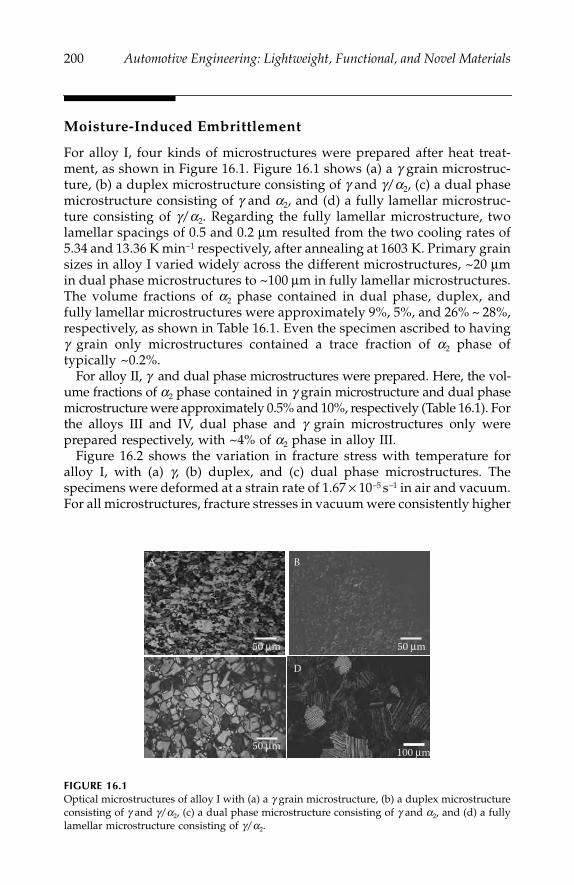
200
Automotive Engineering: Lightweight, Functional, and Novel Materials
Moisture-Induced Embrittlement
For alloy I, four kinds of microstructures were prepared after heat treat-ment, as shown in Figure 16.1. Figure 16.1 shows (a) a
g
grain microstruc-ture, (b) a duplex microstructure consisting of
g
and
g
/
a
2
, (c) a dual phasemicrostructure consisting of
g
and
a
2
, and (d) a fully lamellar microstruc-ture consisting of
g
/
a
2
. Regarding the fully lamellar microstructure, twolamellar spacings of 0.5 and 0.2
μ
m resulted from the two cooling rates of5.34 and 13.36 K min
−
1
respectively, after annealing at 1603 K. Primary grainsizes in alloy I varied widely across the different microstructures, ~20
μ
min dual phase microstructures to ~100
μ
m in fully lamellar microstructures.The volume fractions of
a
2
phase contained in dual phase, duplex, andfully lamellar microstructures were approximately 9%, 5%, and 26% ~ 28%,respectively, as shown in Table 16.1. Even the specimen ascribed to having
g
grain only microstructures contained a trace fraction of
a
2
phase oftypically ~0.2%.
For alloy II,
g
and dual phase microstructures were prepared. Here, the vol-ume fractions of
a
2
phase contained in
g
grain microstructure and dual phasemicrostructure were approximately 0.5% and 10%, respectively (Table 16.1). Forthe alloys III and IV, dual phase and
g
grain microstructures only wereprepared respectively, with ~4% of
a
2
phase in alloy III.Figure 16.2 shows the variation in fracture stress with temperature for
alloy I, with (a)
g
, (b) duplex, and (c) dual phase microstructures. Thespecimens were deformed at a strain rate of 1.67
×
10
-
5
s
-
1
in air and vacuum.For all microstructures, fracture stresses in vacuum were consistently higher
FIGURE 16.1
Optical microstructures of alloy I with (a) a
g
grain microstructure, (b) a duplex microstructureconsisting of
g
and
g
/
a
2
, (c) a dual phase microstructure consisting of
g
and
a
2
, and (d) a fullylamellar microstructure consisting of
g
/
a
2
.
50 μm 50 μm
A B
C D
50 μm 100 μm
IP155_C016.fm Page 200 Monday, December 31, 2007 5:03 PM
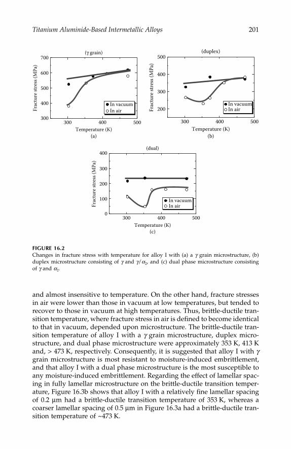
Titanium Aluminide-Based Intermetallic Alloys
201
and almost insensitive to temperature. On the other hand, fracture stressesin air were lower than those in vacuum at low temperatures, but tended torecover to those in vacuum at high temperatures. Thus, brittle-ductile tran-sition temperature, where fracture stress in air is defined to become identicalto that in vacuum, depended upon microstructure. The brittle-ductile tran-sition temperature of alloy I with a
g
grain microstructure, duplex micro-structure, and dual phase microstructure were approximately 353 K, 413 Kand, > 473 K, respectively. Consequently, it is suggested that alloy I with
g
grain microstructure is most resistant to moisture-induced embrittlement,and that alloy I with a dual phase microstructure is the most susceptible toany moisture-induced embrittlement. Regarding the effect of lamellar spac-ing in fully lamellar microstructure on the brittle-ductile transition temper-ature, Figure 16.3b shows that alloy I with a relatively fine lamellar spacingof 0.2
μ
m had a brittle-ductile transition temperature of 353 K, whereas acoarser lamellar spacing of 0.5
μ
m in Figure 16.3a had a brittle-ductile tran-sition temperature of ~473 K.
FIGURE 16.2
Changes in fracture stress with temperature for alloy I with (a) a
g
grain microstructure, (b)duplex microstructure consisting of
g
and
g
/
a
2
, and (c) dual phase microstructure consistingof
g
and
a
2
.
300 400 500
200
300
400
500
Temperature (K)
Frac
ture
stre
ss (M
Pa)
In airIn vacuum
(duplex)
300 400 500300
400
500
600
700
In airIn vacuum
Temperature (K)
Frac
ture
stre
ss (M
Pa)
(γ grain)
(a) (b)
300 400 5000
100
200
300
400
Temperature (K)
Frac
ture
stre
ss (M
Pa)
In airIn vacuum
(dual)
(c)
IP155_C016.fm Page 201 Monday, December 31, 2007 5:03 PM

202
Automotive Engineering: Lightweight, Functional, and Novel Materials
Figure 16.4 shows the variation in fracture stress with temperature foralloy II for (a) a
g
grain microstructure, and (b) a dual phase microstructure.Tensile tests were performed at a slower strain rate of 1.67
×
10
−
6
s
−
1
in bothair and vacuum. The brittle-ductile transition temperature, whereby thefracture stress (or tensile elongation) in air became identical to that in vac-uum, again depended upon the microstructure. Brittle-ductile transition tem-peratures of alloy II with a
g
grain microstructure and a dual phasemicrostructure were approximately 413 K and >473 K respectively, indicat-ing that alloy II with a
g
grain microstructure was more resistant to themoisture-induced embrittlement than dual phase microstructures, and con-sistent with the behavior of alloy I.
FIGURE 16.3
Changes in fracture stress with temperature for alloy I with a fully lamellar microstructureconsisting of
g /a
2
with lamellar spacing of (a) 0.5
μ
m and (b) 0.2
μ
m.
FIGURE 16.4
Variation in fracture stress with temperature for alloy II with a (a)
g
grain microstructure, and(b) dual phase microstructure consisting of
g
and
a
2
.
300 400 5000
100
200
300
400
500
In airIn vacuum
Temperature (K)
Frac
ture
stre
ss (M
Pa)
300 400 5000
100
200
300
400
500
In airIn vacuum
Temperature (K)
Frac
ture
stre
ss (M
Pa)
300 400 500250
300
350
400
450
Temperature (K)
Frac
ture
stre
ss (M
Pa)
In vacuumIn air
(γ grain)b
(b)(a)
300 400 500100
200
300
400
500
Temperature (K)
Frac
ture
stre
ss (M
Pa)
In vacuumIn air
(dual)
IP155_C016.fm Page 202 Monday, December 31, 2007 5:03 PM
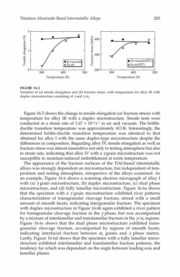
Titanium Aluminide-Based Intermetallic Alloys
203
Figure 16.5 shows the change in tensile elongation (or fracture stress) withtemperature for alloy III with a duplex microstructure. Tensile tests wereconducted at a strain rate of 1.67
×
10
−
6
s
−
1
in air and vacuum. The brittle-ductile transition temperature was approximately 413 K. Interestingly, thedetermined brittle-ductile transition temperature was identical to thatobtained for alloy I with the same duplex-type microstructure despite thedifferences in composition. Regarding alloy IV, tensile elongation as well asfracture stress was almost insensitive not only to testing atmosphere but alsoto strain rate, indicating that alloy IV with a
g
grain microstructure was notsusceptible to moisture-induced embrittlement at room temperature.
The appearance of the fracture surfaces of the TiAl-based intermetallicalloys was strongly dependent on microstructure, but independent of tem-perature and testing atmosphere, irrespective of the alloys examined. Asan example, Figure 16.6 shows a scanning electron micrograph of alloy Iwith (a)
g
grain microstructure, (b) duplex microstructure, (c) dual phasemicrostructure, and (d) fully lamellar microstructure. Figure 16.6a showsthat the specimen with a
g
grain microstructure exhibited river patternscharacterization of transgranular cleavage fracture, mixed with a smallamount of smooth facets, indicating intergranular fracture. The specimenwith duplex microstructure in Figure 16.6b again exhibited a river patternfor transgranular cleavage fracture in the
g
phase, but was accompaniedby a mixture of interlamellar and translamellar fracture in the
g
/
a
2
regions.Figure 16.6c shows that the dual phase microstructure exhibited trans-granular cleavage fracture, accompanied by regions of smooth facets,indicating interfacial fracture between
a
2
grains and
g
phase matrix.Lastly, Figure 16.6d shows that the specimen with a fully lamellar micro-structure exhibited interlamellar and translamellar fracture patterns, thetendency for which was dependant on the angle between loading axis andlamellar planes.
FIGURE 16.5
Variation of (a) tensile elongation and (b) fracture stress, with temperature for alloy III withduplex microstructure consisting of
g
and
g /a
2
.
300 400 5000
1
2
Temperature (K)
Tens
ile el
onga
tion
(%)
In vacuumIn air
300 400 500200
300
400
Temperature (K)
Frac
ture
stre
ss (M
Pa)
In vacuum(RT)In air(RT)
IP155_C016.fm Page 203 Monday, December 31, 2007 5:03 PM

204
Automotive Engineering: Lightweight, Functional, and Novel Materials
Embrittlement Mechanism
It has been suggested that the moisture-induced embrittlement of many inter-metallic alloys including TiAl is induced at ambient temperature by decom-position of moisture on the alloy surface (or freshly exposed grain boundariesor cleavage planes), and subsequent micro-processes, such as permeation ofatomic hydrogen into the alloy, and the migration and condensation of atomichydrogen to grain boundaries (or lattice planes) in front of a propagatingmicro-crack. The grain boundary cohesion (or lattice cohesion) and the asso-ciated plastic work can be reduced by hydrogen condensation under the influ-ence of a stress field ahead of a propagating micro-crack, thereby resulting inbrittle intergranular fracture (or cleavage fracture).
11–13
It is suggested furtherthat when the ambient temperature increases, the amount of absorbed hydro-gen reduces, because of the lowering of the relative humidity, or from theformation of a protective surface oxide film. Consequently, hydrogen concen-tration does not reach the critical value to facilitate the subsequent propagationof a micro-crack. The recovery of tensile elongation occurs in a manner similarto the brittle-ductile transition with temperature, and the moisture-inducedembrittlement generally disappears at high temperatures.
14,15
FIGURE 16.6
SEM fractographs of alloy I with a (a)
g
grain microstructure, (b) duplex microstructure con-sisting of
g
and
g
/
a
2
, (c) dual phase microstructure consisting of
g
and a2, and (d) fully lamellarmicrostructure consisting of g/a2.
500 50μm 50μm 0005 Ti2Moair15kV 500
50μm 0005 2TiA15kV 20kV500 50μm 1350 tanzouFL500
0010 tanzou
A
C
B
D
IP155_C016.fm Page 204 Monday, December 31, 2007 5:03 PM

Titanium Aluminide-Based Intermetallic Alloys 205
Based on the measured temperatures at which the moisture-inducedembrittlement of the TiAl-based intermetallic alloys disappears in thisstudy, the g grain microstructure is the most resistant to moisture-inducedembrittlement, and the dual phase microstructure is the most susceptibleto moisture-induced embrittlement. A duplex microstructure has moderatesusceptibility/resistance to moisture-induced embrittlement. Similarly, afully lamellar microstructure shows moderate susceptibility/resistanceto moisture-induced embrittlement, and is dependent upon the lamellarspacing.
As the microstructural parameters relevant to the moisture-inducedembrittlement of the TiAl-based intermetallic alloys, the volume fraction ofa2 phase, grain (or lamellar cell) size and grain (or lamellar) morphologymust also be considered, and their values are shown in Table 16.1.
Let us firstly consider the moisture-induced embrittlement of the speci-mens with g grain, dual phase, and duplex microstructures. Here, grain sizemay be excluded as a primary factor in determining moisture-inducedembrittlement behavior, since alloy I with a duplex microstructure with thesmallest grain size (25 μm) is not resistant to moisture-induced embrittlement;and alloy IV with a g grain microstructure and the largest grain size (50 μm) isnot the most susceptible to moisture-induced embrittlement (Table 16.1). How-ever, moisture-induced embrittlement behavior becomes more pronouncedas the volume fraction of a2 phase increases. In other words, as the micro-structure changes from a g grain microstructure to a duplex microstructurethrough a dual phase microstructure, the moisture-induced embrittlementresponse becomes more severe. As shown in Table 16.1, the volume fractionof a2 phase in the g grain microstructure was 0.2, 0.5, and 0% in alloys I, II,and IV, respectively; 5 and 4% in duplex microstructure alloys I and III,respectively; and 9 and 10% in dual microstructure alloys I and II, respec-tively. Thus, the results shown here suggest strongly that a2 volume fractiongreatly affects the moisture-induced embrittlement of TiAl-based interme-tallic alloys.
The precise role that a2 phase plays in this embrittlement of TiAl-basedalloys is unclear. One possible explanation is that the interface betweena2 phase grain and g grain matrix acts as a preferable trap site for hydrogenatoms, and that interfacial cohesive strength is subsequently reduced, result-ing in easier interfacial fracture. An alternative explanation may be that thea2 phase grains scavenge atomic hydrogen from the g grain matrix, but doesnot so effectively reduce the moisture-induced embrittlement of the alloywith this type of microstructure. The a2 phase grains may be rather moresusceptible to the moisture-induced embrittlement than other constituentphase (g phase) by absorbing atomic hydrogen. It has been reported thatTi3Al a2-based alloys, such as Ti-25Al-10Nb-3V-1Mo and Ti-24Al-11Nballoys, were embrittled by thermal exposure to hydrogen at high tempera-ture, and their embrittlement was attributed to the formation of hydridesand their subsequent brittle fracture.16–19
IP155_C016.fm Page 205 Monday, December 31, 2007 5:03 PM

206 Automotive Engineering: Lightweight, Functional, and Novel Materials
The fully lamellar microstructure consisting of g /a2 showed moderatesusceptibility to moisture-induced embrittlement, the extent of whichstrongly depended on the lamellar spacing, despite the large fraction of a2
phase present. Because moisture-induced embrittlement becomes weaker asthe lamellar spacing decreases, it is suggested that the morphology of thelamellae and the increase in the area of interface between g and a2 phasessuppresses moisture-induced embrittlement. In contrast to the a2/g inter-faces in the other microstructures, the a2/g interfaces in fully lamellar micro-structures are composed of coherent (or semi-coherent) structures.Consequently, different hydrogen behavior and mechanical response maybe expected at the a2/g interfaces in a fully lamellar microstructure. Forexample, the absorbed hydrogen may migrate and/or be trapped on themany interfaces between g and a2 lamellae, and consequently does not reachthe critical concentration beyond which interlamellar fracture occurs. Inother words, the large interfacial area between g and a2 lamellae and thehigh density of trap sites for hydrogen reduces hydrogen content on theseplanes, resulting in a reduction in moisture-induced embrittlement.
Summary
TiAl-based intermetallic alloys with various microstructures of g grains, aduplex microstructure consisting of g and g/a2, a dual phase microstructureconsisting of g and a2, and a fully lamellar microstructure consisting of g/a2
were prepared from isothermally forged materials. These TiAl-based inter-metallic alloys were tensile tested in vacuum and air as functions of temper-ature from room temperature to 473 K, and the microstructural effect on anymoisture-induced embrittlement studied. It has been concluded that:
1. All the alloys and microstructures showed reduced tensile strength(or elongation) in air at room temperature. Tensile strength (orelongation) of the specimens deformed in air tended to recover tothe values of the specimens deformed in vacuum, as temperatureincreased.
2. The measured tensile recovery temperatures indicated that theγ grain microstructure was the most resistant to moisture-inducedembrittlement, and the dual phase microstructure was the mostsusceptible to moisture-induced embrittlement.
3. The moisture-induced embrittlement of the specimens with a fullylamellar microstructure was dependent upon the lamellar spacing,and was reduced with decreasing lamellar spacing.
4. The observed moisture-induced embrittlement of TiAl-based inter-metallic alloys has been discussed in terms of the possible behaviorof atomic hydrogen and its subsequent effects on mechanicalresponse in different TiAl-based alloy microstructures.
IP155_C016.fm Page 206 Monday, December 31, 2007 5:03 PM

Titanium Aluminide-Based Intermetallic Alloys 207
References
1. Huang, S. C., and J. C. Chesnutt, Intermetallic Compounds, Volume 2, Practice,J. H. Westbrook, and R. L. Fleischer, eds., John Wiley and Sons, West Sussex,England, 73, 1995.
2. Kim, Y. -W., J. Metals, Vol. 41, 24, 1989.3. Tsujimoto, T., and K. Hashimoto, Mater. Res. Soc. Symp. Proc., Vol. 133, 391, 1989.4. Huang, S. C., and E. L. Hall, Acta Metall. Mater., Vol. 39, 1053, 1991.5. Kim, Y. -W., Acta Metall. Mater., Vol. 40, 1121, 1992.6. Yamaguchi, M., H. Inui, K. Kishida, M. Matsumoto, and Y. Shirai, Mater. Res.
Soc. Symp. Proc., Vol. 364, 3, 1995.7. Takasugi, T., and S. Hanada, J. Mater. Research, Vol. 7, 2739, 1992.8. Liu, C. T., and Y. –W. Kim, Scripta Metall., Vol. 27, 599, 1992.9. Nakamura, M., K. Hashimoto, T. Tsujimoto, and T. Suzuki, J. Mater. Res, Vol. 8,
68, 1993.10. Nakamura, M., N. Itoh, K. Hashimoto, T. Tsujimoto, and T. Suzuki, Metall.
Trans. A, Vol. 25, 321, 1994.11. Takasugi, T., Critical Issues in the Development of High Temperature Structural
Materials, N. Stoloff, D. J. Duquette, and A. F. Giamei, eds., TMS, Warrendale,PA, 399, 1993.
12. Liu, C. T., 6th Int. Symp. Intermetallic Compounds—Structure and MechanicalProperties, O. Izumi, ed., JIM, 703, 1991.
13. Liu, C. T., and E. P. George, International Symposium on Nickel and Iron Aluminide:Processing, Properties, and Applications, C. Deevi, V. K. Sikka, P. J. Maziasz, andR. W. Cahn, eds., ASM, 21, 1997.
14. Takasugi, T., T. Tsuyumu, Y. Kaneno, and H. Inoue, J. of Materials Research,Vol. 15, 1881, 2000.
15. Kaneno, Y., M. Wada, H. Inoue, and T. Takasugi, Materials Transaction, Vol. 42,418 2001.
16. Stoloff, N., Hydrogen Effects on Materials Behavior, N. R. Moody, and A. W. Thompson,eds., TMS, 483, 1990.
17. Chu, W. –Y., and A. W. Thompson, Meta. Trans. A, Vol. 23, 1299, 1992.18. Fitzemeir, L. G., and M. A. Jacinto, Hydrogen Effects on Materials Behavior,
N. R. Moody, and A. W. Thompson, eds., TMS, 533, 1990.19. Chan, K., Metall. Trans. A, Vol. 24, 1095, 1993.
IP155_C016.fm Page 207 Monday, December 31, 2007 5:03 PM

IP155_C016.fm Page 208 Monday, December 31, 2007 5:03 PM
209
17
Casting Processes and Simulation Tools
Mark Jolly
CONTENTS
Introduction .........................................................................................................210Reputation of Shaped Castings ........................................................................ 211Process Control....................................................................................................213Filling Problems ..................................................................................................213Guidelines for Making High-Integrity Castings ...........................................214Processes...............................................................................................................216Simulation Tools of Casting Processes ............................................................224Numerical Techniques........................................................................................224
Physics and Mathematical Solutions......................................................224Finite Difference Methods........................................................................225Finite Element Methods............................................................................225Differences between Finite Difference
and Finite Element Methods .......................................................225Heuristic Techniques .................................................................................226Meshing or Discretization ........................................................................226
Thermo-Physical Data and Boundary Conditions ........................................227Boundary Conditions and Issues with Casting Processes..................227Thermo-Physical Data...............................................................................229Viewing Results .........................................................................................230Filling ..........................................................................................................230Solidification ...............................................................................................232Microstructure Prediction.........................................................................232Mechanical Property Prediction..............................................................234Stress, Distortion, and Shape Prediction ...............................................235
Other Processes in the Manufacture of Castings ..........................................235Future....................................................................................................................235Summary ..............................................................................................................236References
..........................................................................................
236
IP155_C017.fm Page 209 Tuesday, January 8, 2008 12:13 PM
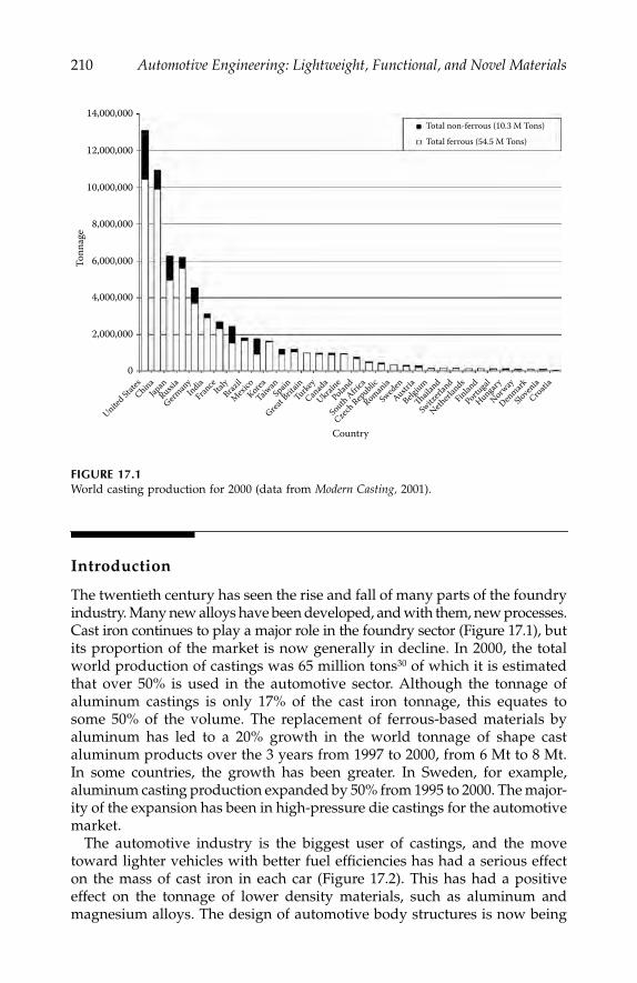
210
Automotive Engineering: Lightweight, Functional, and Novel Materials
Introduction
The twentieth century has seen the rise and fall of many parts of the foundryindustry. Many new alloys have been developed, and with them, new processes.Cast iron continues to play a major role in the foundry sector (Figure 17.1), butits proportion of the market is now generally in decline. In 2000, the totalworld production of castings was 65 million tons
30
of which it is estimatedthat over 50% is used in the automotive sector. Although the tonnage ofaluminum castings is only 17% of the cast iron tonnage, this equates tosome 50% of the volume. The replacement of ferrous-based materials byaluminum has led to a 20% growth in the world tonnage of shape castaluminum products over the 3 years from 1997 to 2000, from 6 Mt to 8 Mt.In some countries, the growth has been greater. In Sweden, for example,aluminum casting production expanded by 50% from 1995 to 2000. The major-ity of the expansion has been in high-pressure die castings for the automotivemarket.
The automotive industry is the biggest user of castings, and the movetoward lighter vehicles with better fuel efficiencies has had a serious effecton the mass of cast iron in each car (Figure 17.2). This has had a positiveeffect on the tonnage of lower density materials, such as aluminum andmagnesium alloys. The design of automotive body structures is now being
FIGURE 17.1
World casting production for 2000 (data from
Modern Casting,
2001).
14,000,000
12,000,000
10,000,000
8,000,000
6,000,000
4,000,000
Tonn
age
2,000,000
0
Country
Total non-ferrous (10.3 M Tons)
Total ferrous (54.5 M Tons)
United Stat
esChina
JapanRussi
a
German
yIndia
FranceIta
lyBraz
il
MexicoKorea
Taiwan
Spain
Great B
ritainTurke
y
Canad
a
UkrainePolan
d
South Africa
Czech Rep
ublic
Romania
Sweden
Austria
Belgium
Thaila
nd
Switzerl
and
Netherl
ands
Finland
Portugal
Hungary
Norway
Denmark
Slovenia
Croatia
IP155_C017.fm Page 210 Tuesday, January 8, 2008 12:13 PM

Casting Processes and Simulation Tools
211
revisited. Every major car producer has now developed an
“aluminum car.”
It is actually the body that is aluminum, including the structural components.Some companies have relied solely on aluminum extrusions, but a numberhave used aluminum cast nodes to join the extruded sections together, and insome cases, castings have been used as items such as B-pillars (Figure 17.3).
Reputation of Shaped Castings
Castings do not have a good reputation within the engineering community.Figure 17.4 shows the scrap rates of component suppliers to a major auto-motive company indicating that the worst five suppliers are foundries. Often,cast components that are going to be placed under high loads will have acasting factor included in the design that can be as large as 10.
18
In otherwords, the designer is saying that he can only rely on one-tenth of thepublished mechanical properties in that cast component. Unfortunately,foundrymen (and it has generally been men) have created this situation bytreating the casting process as an art rather than a branch of engineering.Casting is a highly technical engineering process requiring much scientificunderstanding, and will give sound reliable products if carried out correctly.
On the other hand, designers and engineers are recognizing the advantagesthat using castings may give: design flexibility, part number reduction byconsolidation of fabricated parts into single components, near-net-shapeproduction processes, to name a few. However, these attractive advantagesraise other problems associated with design for manufacturing for a process
FIGURE 17.2
Chart showing the change in share of materials in cars over the years between 1980 and 1995.
60
50
40
30
20
Perc
enta
ge b
y wei
ght
10
0Steel Plastic Cast iron
Material
19801995
Change in Materials Share in Cars 1980 to 1995
Aluminum Others
IP155_C017.fm Page 211 Tuesday, January 8, 2008 12:13 PM

212
Automotive Engineering: Lightweight, Functional, and Novel Materials
FIGURE 17.3
The Audi A2 space-frame. 22.1% of the A2 is made of castings. The cast parts of the space-frame are marked in red in the schematic. The casting on the right is the B pillar and is a high-pressure die-casting made using a vacural type procedure.
FIGURE 17.4
Suppliers to a major automotive manufacturer in 1995 showing reject rates. Note the five worstsuppliers were foundries.
70
ppm × 1000
Foundries
60
50
40
30
20
10
0
IP155_C017.fm Page 212 Tuesday, January 8, 2008 12:13 PM

Casting Processes and Simulation Tools
213
for which a large number of automotive designer engineers appear to havelittle, or no comprehension. Consequently, foundries are asked to manufac-ture components that have not been designed with processing in mind, andthe poor reputation of castings is then recycled!
Process Control
The level of process control required to produce castings reliably is veryhigh. Composition, temperature of melt and mould, speed of filling, qualityof mould/die, and many other factors influence the process, but the mainissues that require a good understanding of the science of the process arethe quality of liquid metal and the filling, shrinkage, and thermal patternswhile the casting is in the liquid state. Castings have mainly been unreliablebecause they contain porosity. Some of these pores arise from solidificationshrinkage, but the majority of them arise from damaged metal. In otherwords during the processing of the liquid metal, defects have beenintroduced
5
mainly due to the handling of the liquid metal, that regardlessof how one changes the mould or metal temperature will cause the castingsto be unreliable under an applied stress.
20
The causes and nature of thesedefects are discussed below.
Filling Problems
The way in which liquid metal is handled and distributed into a mould cavityis probably the single most important factor affecting the quality and pro-perties of a casting. It is, therefore, strange that the foundry industry andtheir customers seem to believe that it is the last thing to consider in thedesign of a casting, and its associated manufacturing process. Work at theUniversity of Birmingham, in the Castings Research Group and the CastingsCentre working with industry, and an increasing number of laboratoriesaround the world, has shown that considerable improvements can be madeto casting quality by paying attention to the fine detail of the fluid dynamics.When the filling of castings is addressed correctly, the feeding of castings, aboutwhich many words have been written, and about which every foundrymanhas an opinion, becomes a secondary problem.
However, all is not lost! It is heartening to see that a number of equipmentmanufacturers are designing processes with the quiescent filling of mouldsbeing a prime consideration for aluminum alloys. What now has to beaddressed is how to raise the awareness of the rest of the industry to the
IP155_C017.fm Page 213 Tuesday, January 8, 2008 12:13 PM

214
Automotive Engineering: Lightweight, Functional, and Novel Materials
fact that quiescent, i.e., non-turbulent (not slow) filling is a prerequisite forquality castings. This means all castings, not just aluminum alloys.
Recent work with a number of grey iron foundries has shown that thepoor design of filling systems causes most of their scrap. Shrinkage, andtherefore feeding, is rarely, if ever, a problem. Slag defects, lustrous carbonfilms, entrapped bubbles, and sand inclusions give rise to the largest pro-portion of defects for these automotive suppliers. Such defects only arisefrom turbulent filling. Traditional iron-gating systems are designed to shootthe metal into a casting by using the gate (the place where the metal passesthrough into the casting itself) as a choke, which is the place where the metalis traveling fastest. Choke is, therefore, the wrong word! The other traditionalview about “the spinner” (a centrifugal trap) cleaning the metal, using thesame principal as the spin cycle on a washing machine, is usually completelywrong. The idea is sound, of course, but it is the application of the idea thatis incorrect. It has been shown by computer modeling that in the designs ofspinners used, the liquid metal takes the shortest path between the inlet andthe outlet, i.e., a straight line. At best, the spinner reduces the “yield” (massof castings made, expressed as a percentage of total metal poured), and atworst, it introduces more slag defects.
Introduction of flat, light, filter-containing running systems into a UK greyiron automotive component supplier has enabled them to start to achievethe very stringent scrap rates imposed by a large, automotive customer. Withthe original running system, which had been developed over a 15-yearperiod, the scrap rate was a respectable 1.3%. After applying a runningsystem designed using a combination of fluid dynamics, simulation, andpractical feedback, castings showed a scrap rate of some 0.3%, of which only0.15% was due to slag. All the intricacies of controlling molten iron to giveslag-free castings are yet to be understood, but the application of soundscientific principles has helped create the step change in defect levels. Adrawback, or in hindsight, probably an advantage of the approach, has beenthat all the other aspects of the process that give rise to problems have alsobeen revealed. For example, control of pouring temperature, placement offilters, glue line procedures, mechanical handling, and mould manufacturehave since all come under scrutiny as they are highlighted as causing specificdefects that were previously hidden in the overall scrap figures.
Guidelines for Making High-Integrity Castings
Campbell
4
has proposed and Runyoro
37
demonstrated that the overridingfeature for good filling of castings is that the metal velocity should never begreater than the critical velocity for surface turbulence. For the majority ofengineering casting alloys, critical velocities are in the range 0.4 to 0.6 ms
−
1
.This means that throughout the time when the metal is liquid, it should
IP155_C017.fm Page 214 Tuesday, January 8, 2008 12:13 PM

Casting Processes and Simulation Tools
215
never be subjected to a velocity greater than this value. This has majorramifications on processes, especially high-pressure die-casting, where thevelocity is often as high as 80 ms
−
1
. Even in gravity processes, the metal canachieve velocities of 3
–
4 ms
−
1
in larger castings, and for Al, the metal onlyhas to fall 12 mm at any point to achieve that velocity. This implies thatprocesses in which the metal enters the mould from the bottom, or in whichthe mould is rotated, should be inherently better than those where the metalis allowed to fall, or is highly pressurized during the filling. Carrying outWeibull statistical analysis on castings produced using quiescent fillingrather than turbulent filling shows that the Weibull modulus can beincreased by a factor of between 2 and 5, indicating greater uniformity ofproperties, i.e., the spread of results is much narrower.
13
Campbell has published a series of guidelines for the production of high-quality castings and these are often known as the ten commandments.
6
1. Start with
clean metal
when charging and do not introduce inclu-sions into the metal.
2. Avoid
meniscus damage
by keeping the metal front velocity belowthe critical value for surface turbulence.
3. Avoid
liquid front stopping damage
by never allowing the metalfront to stop moving during the filling process.
4. Avoid
bubble damage
by preventing the entrainment of air intothe casting at any point.
5. Reduce
core blows
by good design and positioning of cores withproper venting.
6. Avoid
shrinkage damage
by ensuring correct feeding, and nevertry to feed uphill.
7. Avoid
convection damage
by ensuring there are no convectionloops created during filling.
8. Stop
unplanned segregation
by understanding and controlling thetemperature gradients within the casting.
9. Control
residual stress
by good design, and better heat treatmentprocess—for aluminum avoid quenching in water.
10. Avoid
machining damage
by using a recognized through-processsystem of datums and location points.
It is impossible to achieve some of these with some manufacturing processes,but the closer the process is to achieving these, then the higher the integrityof castings produced. These guidelines do not consider economic factors.
Most of the work carried out at Birmingham has been on gravity pouredsystems including sand, shell, investment and metal moulds, or dies,although a limited amount of work has been on low-pressure systems. Recentanalyses of high-pressure die-casting failures have revealed that the fillingmethod was the main reason for malfunction of products. It does not matter
IP155_C017.fm Page 215 Tuesday, January 8, 2008 12:13 PM

216
Automotive Engineering: Lightweight, Functional, and Novel Materials
how high the pressure applied to the liquid is during solidification, onceturbulence and turbulence-related defects are created, they do not disap-pear—they remain within the component, undetectable and unpredictableuntil a post-mortem is performed, and the design engineers yet again pro-nounce that castings are unreliable.
Processes
Foundry processes can be split into two main categories: gravity processes,in which the liquid metal is allowed to enter the mould with no externallyapplied pressure, and pressurized systems, in which pressure is applied tomove the metal into the mould/die cavity. When pressurized systems areused, the pressure can also be applied during solidification, in an attemptto improve the soundness of the solid metal.
The physics of casting processes has to deal with extremes. For example,in general for sand casting, except in extremely large castings, the velocityof the liquid ranges from 0.1 to 5 ms
−
1
. However, in high-pressure die-casting,the liquid metal velocity is in the range of 40 to 80 ms
−
1
. Similarly, theexternally applied pressure ranges from zero in gravity processes to 250 MPain squeeze casting.
In the automotive sector, most casting processes are used. Unfortunately,there is still competition between processes for similar parts because no onehas arrived at a formula (or one that is accepted) that considers all thevariables of the process, including order size, surface finish, part quality, etc.In fact, there is often a problem defining acceptable quality.
Sand casting
can be used for the majority of metals. Even highly reactivemagnesium is sand cast provided care is taken and the correct materials used.
Sand castings inevitably have a slow cooling rate because of the largeinsulating mass of sand surrounding the liquid metal as it cools.
Grain sizes
and
dendrite arm spacings
tend to be larger than in the equivalent section sizesin die-castings. Cooling rates in sand castings range from 10
−
6
°Cs
−
1
to 1°Cs
−
1
,and the expected dendrite arm spacing may be from 50
µ
m to 5 mm.
22
Surfacefinish for sand castings depends on the fineness of the sand and the qualityof the tooling, but is generally poorer than die castings or those producedwith externally applied pressure. Minimum section thicknesses achievablein non-pressurized sand castings are about 2
–
3 mm in aluminum and 3
–
4mm in iron.
In
permanent mould casting
(gravity die-casting in the United Kingdom),the component shape is formed from a female cavity, the die of which isusually made of steel or cast iron. Dies are usually sculpted rather thanmonolithic. Cores can be incorporated that can be manufactured from sandor metal. Inserts of different materials that remain in the final component(for example, threaded bushes for bolts, or stainless steel cooling tubes), can
IP155_C017.fm Page 216 Tuesday, January 8, 2008 12:13 PM
Casting Processes and Simulation Tools
217
also be incorporated. Pouring of gravity die-castings can be automated inlarge automotive foundries, but is often manual. Some foundries also tiltduring pouring, in an attempt to try to control the metal flow. However,recent work has shown that controlling the flow by tilt pouring requirescomplex control over the rotation rate, and the accelerations and decelera-tions involved.
21
The surface finishes of permanent mould castings is a little better than forsand castings, and is heavily influenced by any coatings that are used andby the position of the surface in the mould cavity. The cooling rates for theprocess will give dendrite arm spacings in thinner sections of 5
µ
m to 50
µ
m.Although some foundries have used the permanent mould process for cast-ing iron components, this is relatively rare; it is more usually used for non-ferrous casting alloys, especially of aluminum. In these alloys, the mostcommon uses are for automotive cylinder heads, pistons, blocks, and cast-ings, where a
heat-treatable casting
is required, often with a specified dendritearm spacing. Minimum section thicknesses for aluminum alloys in perma-nent mould casting are 4 to 5 mm. This is determined by the solidificationtime of the section.
In the
resin shell
or
Croning process
, the mould is made from sand, which is pre-coated with a phenolic
resin, blown onto a metal pattern plate (the positive),and cured in an oven. The resulting mould is a thin (up to 15 mm) shell ofsand, which usually has a very fine internal surface finish. The moulds canbe cored, and chill inserts can be used in order to vary cooling rates.Insulation can also be put on the outside of the shell, if necessary. The splitline, of which there can only be one, can be either horizontal or vertical.Pouring can be either automated, semi-automated, or by hand, althoughthere is a predominance of hand pouring in foundries using this process.Filters can be incorporated into the running system. During pouring, andsubsequent solidification, the mould may be placed in a container of steelshot (backing), or on a bed of sand, or straight onto a conveyor track.
The surface finish achieved by resin shell casting is generally superior tosand casting, as is the dimensional accuracy, although this depends on themould–making process. The process tends to be used for higher meltingpoint alloys, such as iron, steel, and copper. Components are usually in thekilograms to tens of kilogram size range, and examples of automotive com-ponents are cam-shafts, crank-shafts, tappets, buckets, shims, and slippers.It is often used where chilled white iron is required.
In
lost foam casting
(
evaporative pattern process
),
a male copy of the com-ponent to be cast is manufactured in polystyrene by blowing into a femaledie cavity. The polystyrene pattern is then coated with a thin ceramic slurryand dried. The pattern is then placed in a box, and loose sand without abinder is poured around it. The box is usually vibrated to increase thepacking density of the sand, and sometimes a vacuum is applied to thebox to increase its firmness. Metal is then poured on to the pattern, whichdecomposes into gaseous materials as it comes into contact with the moltenmetal.
IP155_C017.fm Page 217 Tuesday, January 8, 2008 12:13 PM
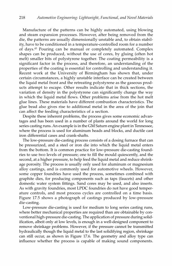
218
Automotive Engineering: Lightweight, Functional, and Novel Materials
Manufacture of the patterns can be highly automated, using blowingand steam expansion processes. However, after being removed from thedie, the patterns are usually dimensionally unstable and, to obtain stabil-ity, have to be conditioned in a temperature-controlled room for a numberof days.
43
Pouring can be manual or completely automated. Complexshapes can be produced, without the use of cores, by gluing (often hotmelt) smaller bits of polystyrene together. The coating permeability is asignificant factor in the process, and therefore, an understanding of theproperties of the coating is essential for controlling and understanding it.Recent work at the University of Birmingham has shown that, undercertain circumstances, a highly unstable interface can be created betweenthe liquid metal front and the retreating polystyrene as the gaseous prod-ucts attempt to escape. Other results indicate that in thick sections, thevariation of density in the polystyrene can significantly change the wayin which the liquid metal flows. Other problems arise from the hot meltglue lines. These materials have different combustion characteristics. Theglue bead also gives rise to additional metal in the area of the join thatcan affect the feeding characteristics of a section.
Despite these inherent problems, the process gives some economic advan-tages and has been used in a number of plants around the world for longseries casting runs. An example is in the GM Saturn engine plant in Tennessee,where the process is used for aluminum heads and blocks, and ductile castiron differential cases and crank-shafts.
The low-pressure die-casting process consists of a dosing furnace that canbe pressurized, and a steel or iron die into which the liquid metal entersfrom the bottom. It is common practice for low-pressure die-casting found-ries to use two levels of pressure; one to fill the mould quiescently, and thesecond, at a higher pressure, to help feed the liquid metal and reduce shrink-age porosity. The process is usually only used for aluminum or magnesiumalloy castings, and is commonly used for automotive wheels. However,some copper foundries have used the process, sometimes combined withgraphite dies, for producing components such as taps (faucets) and otherdomestic water system fittings. Sand cores may be used, and also inserts.As with gravity foundries, most LPDC foundries do not have good temper-ature controls, and most process cycles are controlled on a time basis.Figure 17.5 shows a photograph of castings produced by low-pressuredie-casting.
Low-pressure die-casting is used for medium to long series casting runs,where better mechanical properties are required than are obtainable by con-ventional high-pressure die-casting. The application of pressure during solid-ification, albeit only at low levels, is enough in a well-designed component toremove shrinkage problems. However, if the pressure cannot be transmittedhydraulically though the liquid metal to the last solidifying region, shrinkagecan still occur, as shown in Figure 17.6. The geometry and alloy type caninfluence whether the process is capable of making sound components.
IP155_C017.fm Page 218 Tuesday, January 8, 2008 12:13 PM
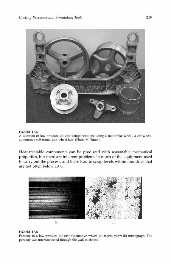
Casting Processes and Simulation Tools
219
Heat-treatable components can be produced with reasonable mechanicalproperties, but there are inherent problems in much of the equipment usedto carry out the process, and these lead to scrap levels within foundries thatare not often below 10%.
FIGURE 17.5
A selection of low-pressure die-cast components including a motorbike wheel, a car wheel,automotive sub-frame, and wheel hub. (Photo M. Turan)
FIGURE 17.6
Porosity in a low-pressure die-cast automotive wheel: (a) macro view; (b) micrograph. Theporosity was interconnected through the wall thickness.
(a) (b)
IP155_C017.fm Page 219 Tuesday, January 8, 2008 12:13 PM
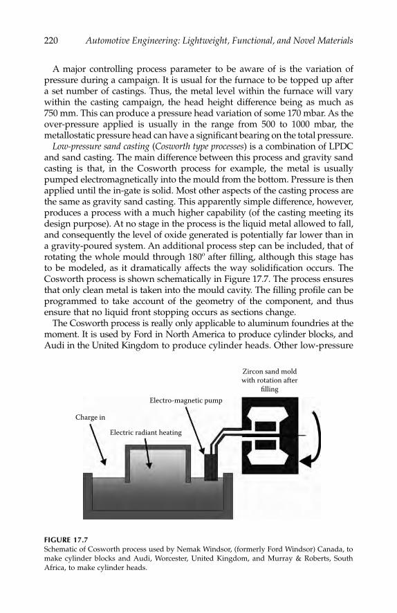
220
Automotive Engineering: Lightweight, Functional, and Novel Materials
A major controlling process parameter to be aware of is the variation ofpressure during a campaign. It is usual for the furnace to be topped up aftera set number of castings. Thus, the metal level within the furnace will varywithin the casting campaign, the head height difference being as much as750 mm. This can produce a pressure head variation of some 170 mbar. As theover-pressure applied is usually in the range from 500 to 1000 mbar, themetallostatic pressure head can have a significant bearing on the total pressure.
Low-pressure sand casting
(
Cosworth type processes
) is a combination of LPDCand sand casting. The main difference between this process and gravity sandcasting is that, in the Cosworth process for example, the metal is usuallypumped electromagnetically into the mould from the bottom. Pressure is thenapplied until the in-gate is solid. Most other aspects of the casting process arethe same as gravity sand casting. This apparently simple difference, however,produces a process with a much higher capability (of the casting meeting itsdesign purpose). At no stage in the process is the liquid metal allowed to fall,and consequently the level of oxide generated is potentially far lower than ina gravity-poured system. An additional process step can be included, that ofrotating the whole mould through 180º after filling, although this stage hasto be modeled, as it dramatically affects the way solidification occurs. TheCosworth process is shown schematically in Figure 17.7. The process ensuresthat only clean metal is taken into the mould cavity. The filling profile can beprogrammed to take account of the geometry of the component, and thusensure that no liquid front stopping occurs as sections change.
The
Cosworth process is really only applicable to aluminum foundries at themoment. It is used by Ford in North America to produce cylinder blocks, andAudi in the United Kingdom to produce cylinder heads. Other low-pressure
FIGURE 17.7
Schematic of Cosworth process used by Nemak Windsor, (formerly Ford Windsor) Canada, tomake cylinder blocks and Audi, Worcester, United Kingdom, and Murray & Roberts, SouthAfrica, to make cylinder heads.
Charge in
Electro-magnetic pump
Zircon sand moldwith rotation after
filling
Electric radiant heating
IP155_C017.fm Page 220 Tuesday, January 8, 2008 12:13 PM
Casting Processes and Simulation Tools
221
sand-casting processes are used by a number of other foundries to pro-duce automotive components. DISA has made developments to its ver-tical split line sand-moulded systems (DISAMATICS) to introduce moltenmetal into the base of the sand moulds. Heinrich Wagner SintoMaschinenfabrik has also applied low-pressure filling to horizontal spiltline sand moulds.
14
Powertrain Ltd. (United Kingdom), a company that waspreviously part of BMW, claimed that the box yield obtainable by its LPSprocess is of the order of 90%
–
95%. The
Alchemy
process was developed bythe BAXI group in the early 1990s to deliver metal into the mould cavity inDISA-type systems.
The
Hitchiner process
was developed at Hitchiner's Technical Center in themid-1970s, and is a counter-gravity investment casting process. In thecounter-gravity low-pressure air melt process (CLA process), the mould is placedin a vacuum chamber with an open snout, or fill pipe, facing down over afurnace of liquid metal. The vacuum chamber is then sealed around the snoutand lowered a precise distance into the melt. A vacuum is then generated,which results in the metal being pressurized by the outside atmosphericpressure into the cavity. After a brief holding time during which the com-ponents and a portion of the gates solidify, the vacuum is released, and theresidual metal in the central snout flows back into the melt. Only a shortgating stub remains on the casting, to be removed automatically by machine.The CLA process allows between 60%–94% of the metal to be used to producea product, compared with 15%–50% in gravity-poured investment processes,where much of the cast weight is in the sprue and gating. The CLA processhas traditionally been used only for ferrous-based materials, but it has greatpotential for aluminum castings. The
CLV process
is a variation of CLA, wherethe metal is melted under a vacuum and so can be used for more reactivemetals. Figure 17.8 shows the CLA and CLV processes.
Unlike gravity-poured parts, which must be cut away from the centralsprue, there is no need to leave room for the cut-off blade in the design ofa CLA casting cluster. As a result, many more parts can be assembled on aCLA sprue. The increase in pattern population per sprue may be two orthree times greater than conventional assemblies. Depending on componentsize and configuration, this has obvious economic ramifications.
The CLA process provides the ability to cast sections thinner than 0.5 mm.Because the sprue is filled in a non-turbulent fashion from clean metalbeneath the surface of the melt, castings with far less slag and non-metallicinclusions are produced. Typically, counter-gravity cast metal contains only15% of the inclusions of poured metal of the same analysis. This cleanermetal has been shown to reduce tool wear by 100% to 500% in comparativemachining tests done under controlled conditions. Because of this and theeconomic benefits of the CLA process over conventional investment casting,it has started to find its way into foundries producing components for theautomotive sector.
Die-casting
or
high-pressure die-casting
(HPDC) is the process whereby liquidalloy is forced at high velocity (up to 80 ms
−
1
) and pressure into steel dies.
IP155_C017.fm Page 221 Tuesday, January 8, 2008 12:13 PM

222
Automotive Engineering: Lightweight, Functional, and Novel Materials
As with LPDC there is usually at least a two-stage pressure cycle of injectionand then intensification. Some of the more modern machines can be pro-grammed to have extremely sophisticated pressure cycles that depend uponthe geometry of the casting. Clamping forces on the dies can be from 50 to5000 tons. Dies are usually monolithic and contain cooling and
/
or heatingchannels. Filling times are measured in tens of milliseconds. Cores are notusually present, as most core materials will not withstand the high-impactforces that occur. In conventional HPDC, the metal entry gate freezes veryquickly, after which time the casting cavity cannot be influenced by theintensification pressure.
There are two types of HPDC machines,
cold chamber
and
hot chamber.
Ingeneral, Zn, Pb, Sn, and Mg alloys castings are made in hot chambermachines, and Al, Cu, and even some ferrous-based alloy castings use coldchamber machines. High-pressure die-casting can produce components thatoften require little or no fettling, or finish machining. The surface finish anddimensional accuracies achievable are also superior to almost any othercasting process. For example, the process is capable of producing castingsroutinely with wall sections of 0.5 mm in Zn alloys.
The problems associated with high-pressure die-castings are always thoseof metallurgical soundness and heat treatability. The very nature of the fillingprocess produces a noncoherent liquid metal stream that initially creates avery thin shell of sound material around the surface of the casting. Theremainder of the volume of the casting is then filled with a mixture of gas
FIGURE 17.8
Hitchiner CLA (a) and CLV (b) processes. In the CLA process the metal is air-melted and inthe CLV process the metal is melted under a vacuum.
(a) (b)
IP155_C017.fm Page 222 Tuesday, January 8, 2008 12:13 PM

Casting Processes and Simulation Tools
223
and alloy. Generally, as the gates used are very thin in section, these freezerapidly before the bulk of the casting is solidified. During the subsequentsolidification, which occurs under ambient pressure, gas bubbles can expandand solidification shrinkage is free to occur. Some dies now incorporateadditional
squeeze pins
to apply further pressure in areas of the casting prone toshrinkage, and these are activated during the solidification phase. As thecastings are often essentially a skin with a core of metal and gas, they cannotbe heat treated effectively.
A number of new developments within the industry have been aimed atovercoming the inherent disadvantages of the process. These start withcontrol over the movement of liquid metal in the shot sleeve before it arrivesat the gates so that metal in the shot sleeve is not damaged by turbulence.Pressure controls throughout the cycle have also made the filling more con-trolled, but generally the velocities are still very much higher than the criticalvelocity for surface turbulence. The
Vacural
process, developed by VAW(Ritter and Santarini 1988) attempts to ensure that there is less air in the castingby evacuating the die cavity just prior to injection. This results in less air toentrain, and better filling, as there is no back pressure. The
pore free process
was developed in Japan and used by ASAHI Aluminum.
1
In this process, themould is filled completely with pure oxygen so that any bubbles formedduring the filling will be just oxygen. The theory is that Al
2
O
3
is formed,consuming all the available oxygen, and thus all the bubbles disappear.
The perceived potential advantages of high-pressure die-casting drives theindustry to seek greater control of the process. Although the process has thepotential to be completely automated, and thus, give a high-process capa-bility from an engineering standpoint, there are many metallurgical issuesthat have to be resolved before the full benefits are achieved.
In the
squeeze-casting
process, liquid metal is introduced into a die cavity,either by direct-pour or via a simple running system. High pressures (up to250 MPa) are applied to the liquid metal so that solidification takes placeunder applied pressure. Dies are usually relatively simple and sand coresare not usually used. There is usually no extra metal needed to supplyfeeding requirements so, theoretically, the yield can approach 100%.
Metal delivery to the die cavity is the weakest part of the process, as thedies are difficult to fill from underneath and then seal against such highpressures. A number of methods are now available by which treated,“undamaged” liquid metal can be introduced into the die. These include theuse of
eyedropper ladles
and liquid metal pumps. There are now a number ofcommercial squeeze-casting machines available on the market.
As well as potentially giving a 100% yield in poured metal, the processenables solidification shrinkage to be eliminated. Cooling rates are high, asthere is intimate contact between the casting and die throughout solidifica-tion. Consequently, fine grain sizes and dendrite arm spacings are achieved,even in thick sections. The main drawbacks of the process are the long cycletimes, which can be as high as five minutes for castings containing thicksections, and the inability to incorporate cores into the geometry.
IP155_C017.fm Page 223 Tuesday, January 8, 2008 12:13 PM

224
Automotive Engineering: Lightweight, Functional, and Novel Materials
Simulation Tools of Casting Processes
The majority of effort in modelling casting has been directed at the filling andsolidification stage of the process. In the shape-casting process, the
method
is theterm used to describe the extra metal added to the component shape in orderto make a casting. The
methods engineer
defines how the metal is to be introducedinto the mould cavity (i.e., the
running system
), and the size and positions of theliquid metal reservoirs for feeding (
feeders
or
risers
). In most foundries, the abilityto perform this function well comes with experience. Much of the methodingthat is performed is highly subject to trial and error.
A number of analytical solutions have been proposed in the past in orderto help the cast metals engineer design for feeding, and thus avoid shrinkage.Those most well-known have been proposed by Chvorinov.
7 who definedthe concept of “modulus” (the ratio of volume to cooling surface area), byWlodawer.50 for directional solidification, and by Niyama et al.35 For theprediction of centerline micro-shrinkage.
Over the past fifteen years or so, there has been a lot of work to developcomputerized simulation programs of the casting process. These simplyreproduce the trial and error methods on a computer rather than on a realcasting. This approach is potentially both quicker and cheaper, and alsoenables a better understanding of metal behavior to be obtained. The majorityof the software packages developed have been devised by a combination ofcomputer, mathematics, and materials specialists who had little or no knowl-edge of foundries and foundrymen, and little practical input. As a result,although there are many software packages for the foundryman to use,fundamental misunderstandings still exist as to their usefulness and suit-ability within the foundry.
Numerical Techniques
Physics and Mathematical Solutions
There are a large number of physical processes that need to be modelled to coverall the shape casting processes. These include heat transfer; including radiation,convection, and conduction; mass transfer (mainly fluid dynamics); phase trans-formations, including solidification and subsequent solid state changes; stress/strain behavior; and microstructural development and segregation of chemicalspecies. The mathematical models used in software codes must also take intoconsideration the conservation of mass, momentum, and energy.
A wide array of mathematical tools is applied to the physical models inorder to solve the physical equations. These come in various guises andcombinations of solutions, and include finite difference (FDM) and finite volume(FVM) methods, finite element methods (FEM), cellular automaton methods
IP155_C017.fm Page 224 Tuesday, January 8, 2008 12:13 PM

Casting Processes and Simulation Tools 225
(CA), and lately, phase field theory.40 Sometimes, there are also combinationsof two techniques, such as the cellular automaton finite element (CAFE) methodproposed by Rappaz and his coworkers.10 Some simple definitions of thetwo main techniques used in macro process modeling are given below.
Finite Difference Methods
The finite difference/volume (FD/FV) method is the title given to a mathematicaltechnique whereby the answer to a complex problem is obtained by dividingup the complete region (known as a domain) of the problem into small pieces(control volumes), and then applying equations to each of these pieces in turn.For each small volume, the calculation assumes that the material propertiesare the same over the complete volume. Consequently, for high accuracy,the domain of calculation must be split into the highest number of cellspossible, or practicable.
Commercial software packages usually apply smoothing algorithms to theresults obtained to remove the steps that occur as a result of the smalldifferences between adjacent control volumes. Thus, the results are adjustedin a post-processing step to give smooth contours. The finite differencecalculations are carried out at predetermined time steps on an iterative basis.Results can be stored at the end of each time step, or after a predeterminednumber of time steps. In general, finite difference methods have been usedto solve fluid dynamics problems where there is a large amount of materialmovement.
Finite Element Methods
The finite element (FE) method again divides the domain of interest intomany parts, but this time they are called elements. The materials propertiesused in the mathematical calculations are stored at the corners (nodes) of eachelement, and sometimes, at other places along the edges of the elements forgreater accuracy. Solutions of a set of equations are then obtained using thesevalues to give a quantity (for example, temperature) for these specific points(Gauss points) within the element. The positions of these points within theelement are determined by the type of integration applied, the initial coordi-nates of the nodes, and the shape of the element. Unlike the finite differencemethods, the values of the variables used in the calculations are not consid-ered constant across the element, but are calculated by using an interpolationmethod. Time is taken into account iteratively, and step-wise. In general, finiteelement methods have been used to solve solid-state problems.
Differences between Finite Difference and Finite Element Methods
It has been demonstrated that finite element and finite difference based pro-grams can both produce simulations of filling and solidification processes tothe same order of accuracy, and are both capable of dealing with unstructured
IP155_C017.fm Page 225 Tuesday, January 8, 2008 12:13 PM
226 Automotive Engineering: Lightweight, Functional, and Novel Materials
meshes. However, a recent survey by Jolly et al. (1996) showed that over50% of the programs used are finite element based, which may indicate thatthese are more popular, especially in the development stage.
One major factor that has hindered the commercialization of finite elementpackages has been mesh generation. In finite difference packages, this hasalways been relatively simple, but automatic meshing for finite elementcodes was not commercially available until 1995.
Heuristic Techniques
These software packages can cause some difficulties in their use because forcommercial reasons, they can produce results without clearly exposing themethodology used. Some of these approaches use a combination of home-grown rules (or encapsulated knowledge statements), and some well-knowncriterion functions, such as the application of Chvorinov’s rule and moduluscalculations. Others are more complex and less driven by geometry. Forexample, one package predicts primary shrinkage and porosity in castingsby first simulating heat flow through a finite difference type mesh in a fullthree-dimensional domain, and then by applying experiential criteria to theresults. Because this approach requires experimental data for each alloy/process combination, it has to be calibrated for each foundry.
With a number of these packages, the results are extremely good, especiallywhere the software has been well calibrated for the alloys being cast. Evenmore impressive is the speed with which such software can produce results.Many of the software packages can produce results for 100 million controlvolumes in a few minutes. More sophisticated software packages may alsoincorporate a quick solution module that is usually rule-based.
Meshing or Discretization
The action of dividing up the three-dimensional (3-D) solid geometry of acasting that is to be simulated is termed “discretization” or more commonly“meshing.” Meshing is one of the most important aspects of the numericalmethods approach and it can heavily influence the results obtained duringthe analysis cycle. Dividing up the 3-D geometry into discrete domains givesrise to numerous problems. For example, representing curved surfaces withcubes inevitably gives rise to steps that hamper any calculations that involveradiation, as the radiating surfaces are all at right angles to each other.Dividing up the object of interest into tetrahedrons, or irregular six-facedcells (hexahedrons) gives a more realistic model for the surface, but givesrise to much more difficult mathematics, especially when dealing with con-servation of mass or volume. However, despite the complex mathematics,in general, stress and flow problems are dealt with better with the less rigidmesh structures, such as those that are hexahedral based. There are stillconcerns over the problems of so-called “mesh diffusion” when using a
IP155_C017.fm Page 226 Tuesday, January 8, 2008 12:13 PM

Casting Processes and Simulation Tools 227
tetrahedral mesh, which is the most common form of automatically gener-ated mesh for finite element codes. The usual method for representingcurved surfaces is by classing a cell that is more than half full of material asfull, and a cell that is less than half full as empty (usually termed markerand cell method, MAC). However, one finite difference-based code, Flow-3D, from Flow Science Inc., Los Alamos, uses advanced mathematical algo-rithms to represent the free surface of both fluids and curved solids in arectangular prismatic mesh. This method, termed volume of fluid, or VOFmethod.34 models a partially full cell interpolating a surface across the cellin a way that is dependent upon the amount of material in the adjacent cells.This gives an excellent representation of the free surface.
Thermo-Physical Data and Boundary Conditions
One of the most difficult aspects of any simulation exercise is the accuraterepresentation of the boundary conditions. When casting simulation wasfirst used in the foundry industry, most of the codes concentrated on thethermal aspects of the problem. At that stage, there was neither the soft-ware nor hardware available to address the problems of filling and liquidmetal flow. Boundary conditions were relatively simple, as air tempera-tures around moulds were assumed to be ambient, and even heat transfercoefficients, although not really known for material combinations, couldbe estimated for different die materials. In reality, boundary conditionsare highly complex, and they may vary considerably through the castingprocess.
Accurate thermo-physical data input, such as solidus and liquidus tem-peratures, latent and specific heats, conductivity, viscosity, and surface ten-sion are important for obtaining meaningful results. Some software packagesprovide the user with a selection of property data for the most commonalloys and moulding materials. However, there can sometimes be quite con-siderable errors in using these data, especially where properties are depen-dent on some other parameter, such as the time or the solid fraction.
Boundary Conditions and Issues with Casting Processes
At present, many of the codes address filling as well as the thermal aspects,and some also have the capability to model evolving stress. This immediatelyraises more issues with regard to boundary conditions. If stress models areused, then the heat transfer coefficients change over the time of the simula-tion as distortion occurs, and gaps are produced between the casting andthe mould or die. The initial boundary conditions for filling can also beextremely complex to set up. For example, during a recent investigation ata UK foundry, it was observed that while semi-mechanical pouring of cast
IP155_C017.fm Page 227 Tuesday, January 8, 2008 12:13 PM

228 Automotive Engineering: Lightweight, Functional, and Novel Materials
iron crankshafts, the metal stream from the lip-poured ladle varied from20 to 40 mm in diameter, and the distance from the top of the pouring bushranged from 150 to 250 mm. This led to changes of inlet velocity at thepouring bush from 1.7 ms−1 to 2.2 ms−1 during the pouring of one singlemould.48 Similar problems have been pinpointed with bottom-poured ladles,as the head height in the ladle will change between the ladle being full andthe ladle being empty. Typically, in a steel foundry, this may mean the exitvelocity in the ladle nozzle can vary by as much as 4 ms−1 from the beginningto the end of pouring.2 The shape of the metal stream will also vary anddepend on whether the metal is lip-poured or bottom-poured.
When simulating any of the die-casting processes, it is usually necessaryto impose an initial uniform temperature on the dies, and then apply several(up to 10) solidification cycles in order to produce a temperature profile forthe steady state condition within the die before completing a full analysisof filling and solidification. Modelling of coatings (or paints), which may beno more than 0.1 mm thick, is not really possible at present, and so, in orderto influence the amount of heat transfer across any coating, a heat transfercoefficient has to obtained for the coatings used, and applied to the surfacesthat are coated. Currently, there is no full, validated database of interfaceheat transfer coefficients for different materials combinations.
The major issues with regard to modelling of the investment casting pro-cess start from the geometrical considerations. Often, the aspect ratio ofthinnest section to overall size of the casting is large. This, therefore, givesproblems during the meshing stage. Other issues relate to the proprietarynature of the shell materials. Each foundry may use its own combinationsof materials, and therefore there is no database of shell material propertiesthat can be usefully created for the foundry community. A method of pre-dicting some of the properties required for modeling is being developedby Jones and coworkers.23 An insulating blanket is sometimes used in an adhoc fashion to reduce the rate of heat loss in certain areas, but chills are notusually used. Radiation is a major consideration in this process, and so thesimulation approach must consider this aspect of heat flow as well as con-duction. In resin shell casting, a backed mould must be modeled differentlyfrom an unbacked mould, where radiation plays a considerable role in theheat transfer processes.
In lost foam casting where pattern parts are glued together, there areproblems in modelling the glue material that usually has very differentproperties form the bulk pattern properties. Other issues arise in trying tomodel the decomposition of the polystyrene. However, work in the UnitedStates is gradually addressing this problem.31 Other results indicate that, inthick sections, the variation of density in the polystyrene can significantlychange the way in which the liquid metal flows, and also influence the localthermal conditions.24
Modelling tilt casting adds to the problems associated with either sand ordie-casting. Knowing how the foundry carries out the tilting, in terms of theequipment stiffness and the angular tilt rate, is extremely important.
IP155_C017.fm Page 228 Tuesday, January 8, 2008 12:13 PM

Casting Processes and Simulation Tools 229
When modelling high-pressure die-casting, the engineer has to be awarethat, unlike in the other casting processes, the metal stream probably doesnot stay coherent, and is more likely to be like a spray of particles. The airin the die is hugely influential on the filling pattern. Venting of the die is,therefore, essential, and should be modeled. Although sand cores are notused in this process, some of the dies used are extremely complex, and thesection thicknesses can be as small as 0.1 mm. Sometimes, additional post-filling pressure is applied by means of “squeeze pins” to specific locationsin the casting, and this is not easy to model.
Thermo-Physical Data
Exothermic materials. It is common practice within steel and some iron found-ries to use exothermic sleeve materials for feeders/risers or “hot toppings.”These are manufactured from materials that produce a thermit type reactionwhen in contact with liquid metal. These are proprietary materials that putheat back into the riser, thus enabling the liquid metal to stay liquid forlonger. Only one serious attempt at measuring these properties has beenmade, and the results to date are proprietary.28 A number of software pack-ages do have the capability of dealing with these materials, provided thatthe thermo-physical data are available, although there are a number of dif-ferent ways in which the materials are treated.
Nonstandard alloys. Exotic or proprietary alloys can often cause a problemfor the foundryman as there is no universal database of thermo-physicaldata for general access. Data for standard alloys now are relatively easy tofind. Data for alloys with slight deviations from standard, or exotic alloyswith low annual production tonnage and potentially with more castingproblems, do not exist in the public domain, and are extremely expensiveto produce. There are, however, a number of software packages that can beused to produce calculated thermo-physical data from chemical composi-tions, such as Thermotec and MTData.
Mould material properties. Thermo-physical data for moulding materialproperties, especially for sand moulds or investment shell moulds, are notwell documented. Problems arise from the very fact that sand propertieswill vary from foundry to foundry. Investment shell technology is oftenunique to a foundry, and regarded as a proprietary art. It is difficult toenvisage how this issue can be resolved completely in modelling. Someheadway is being made by use of some simple rule-based techniques inorder for foundries to be able to estimate certain thermo-physical data.23
Such tools could be applicable to other situations in the foundry, for exam-ple in mould coatings. Work on the modelling of sand core blowing willalso contribute to a better understanding of the effect of cores during thecasting process.38, 49
Interface heat transfer coefficients. The interface heat transfer coefficient isprobably one of the most “fudged” parts of casting modeling. As the mould
IP155_C017.fm Page 229 Tuesday, January 8, 2008 12:13 PM

230 Automotive Engineering: Lightweight, Functional, and Novel Materials
material properties are not accurately known, it is not possible to make accu-rate measurements of interface heat transfer coefficients although, someattempts have been made.25 Often, the mould and the interface are treatedas the same, even though there are certain mechanisms occurring that mustchange the value of heat transfer coefficient during the casting process. Aspreviously discussed, the addition of die coats and mould washes willchange the heat transfer coefficient, and this should be taken into accountin a more systematic way than is currently the practice. Often, interface heattransfer coefficients are used that enable the user of the software to arriveat the correct defect prediction, and studies are continuing to be able topredict values of heat transfer coefficients.16
Viewing Results
Computer simulation software is of no use unless the mass of informationthat is generated can be easily interpreted by those who are making cast-ings, in order for them to change the process in a structured fashion. Withthe development of faster computers, modellers are expected to presentresults in easily digestible images. However, although much of what isseen in computer simulation is still qualitative, work is ongoing to developquantitative methods of analysis of casting processes using modelling asa tool.15
Filling
Relating modelling of filling to casting quality is probably the least well-developed aspect of casting simulation. Filling results can be represented asvelocity vectors, velocity contour maps, and temperature distributions(isothermals) in both 2- and 3-D images. Two-dimensional images are cross-sections through the liquid, and are often easier to understand than a fullytransparent 3-D model, even though a large number of sequential images isrequired to convey all the information about a filling system. Images of thefree surface behavior can also be useful, although surface turbulence usingthese images has to be interpreted carefully. It is also possible to highlightall areas of the liquid metal that are above the critical velocity during anytime step. Particle tracing methods are also used to give some indication ofthe progression of fluid, and the development of phenomena, such as eddiesor strong flow fields.
A more recent development is the association of a scalar value with thefree surface that has time dependence, and is associated with the oxide-generation mechanisms of free surface turbulence. This enables runningsystems to be evaluated a little more quantitatively. Figure 17.9 shows somemethods of representing the filling of castings.
For high-velocity flows, such as those that occur in high-pressure diecasting, there is some debate as to whether current finite difference (FD) and
IP155_C017.fm Page 230 Tuesday, January 8, 2008 12:13 PM

Casting Processes and Simulation Tools 231
FIGURE 17.9 (a) velocity contours (b) liquid mushy and solid regions during filling of a plate, (c) particle trackingenabling the interpretation of where inclusions might be washed to during the casting process aswell as indications of bulk filling history, the development of dead zones and eddies, (d) renderedsurface of liquid metal, and (e) is a 2-D cross-section through the liquid metal showing fraction ofmaterial and velocity vectors.
(e)
(a) (b)
(c) (d)
1.00
0.83
0.67
0.50
0.33
0.17
0.00
.150.076.002X
–.072–.146–.220
IP155_C017.fm Page 231 Tuesday, January 8, 2008 12:13 PM
232 Automotive Engineering: Lightweight, Functional, and Novel Materials
volume of third (SOLA-VOF) mathematical techniques have the capabilityof representing the highly particulate flow. Some novel techniques are beingadopted and developed to deal with this, such as smoothed particle hydro-dynamics (SPH)8 and meshless methods.26
Solidification
Casting simulation initially started with the prediction of solidificationshrinkage, as this was perceived to be the most prevalent casting problem.Primary shrinkage is now well understood and it is probably one of the mostaccurately predicted of all the defects found in casting. Prediction of micro-shrinkage is more problematic, as the distribution and size of the pores isaffected heavily by both the filling and the solidification behavior of thealloy. Modelling of the internal micro-shrinkage is not routinely carried out,as that would incur huge computional time penalties, although there isresearch work to try to reduce this. More commonly, in order to predictshrinkage, criterion functions are used as a post-processing technique andinvolve consideration of the local conditions of temperature and cooling rate.One such function, the Niyama criterion, is used for short freezing rangealloys, and especially steels, and utilizes the relationship between tempera-ture gradient, G, and the cooling rate, R. A plot is then made of the regionswithin the casting where the value of the criterion function chosen is greateror less than a specific value, which is dependent on the alloy system beingcast. A review of some of these criteria functions has been presented byTaylor et al.41
What is often valuable to the foundryman is to be able to predict the orderof solidification of the various parts of the casting. This can be representedin many ways: as isothermals, isochronals, or liquid/mush/solid fractions.Representation of porosity has always led to an interesting debate. Somesoftware packages represent the porosity as contours of probability of poros-ity, others as discrete “holes” in the casting geometry. Some software pack-ages can also show different levels of porosity depending on what qualitylevel is selected by the operator.
Microstructure Prediction
The routine simulation and prediction of microstructure is fast becoming areality. Predictions of grain size and grain growth, and orientation are beingcarried out at the larger organizations and research establishments, but thesehave yet to make their way onto the shop floor of the smaller foundries.Modelling of grain size, and the production of pole figures of texture inaerofoil castings is now possible, as shown in Figure 17.10. Individual den-drite growth can also be modelled well using either cellular automaton(CA)17 or phase field techniques.47, 46 Figure 17.11 illustrates what can be seen
IP155_C017.fm Page 232 Tuesday, January 8, 2008 12:13 PM

Casting Processes and Simulation Tools 233
from these two types of analysis. However, there is some way to go yetbefore this can be carried out on a full-size casting, as the CPU required fordiscretization at that level is enormous. Voller44 has predicted that withcurrent rates of improvements in hardware and software, it would still takeuntil 2040 to be able to model dendrite tips in a casting space envelope of10 × 10 × 10 cm.
FIGURE 17.10 Prediction of grain structure (a) and orientation with pole figure (b) in a directionally castturbine blade.
(a)
(b)
IP155_C017.fm Page 233 Tuesday, January 8, 2008 12:13 PM

234 Automotive Engineering: Lightweight, Functional, and Novel Materials
Mechanical Property Prediction
It is possible to infer mechanical properties from the thermal history of thecasting. Hardness and strength have both been predicted using these meth-ods, and images mapping contours can be produced.
FIGURE 17.11 (a) and (b) development of 2-D dendritic structure and microsegregation predicted using theCA technique (Jarvis et al. 2000), (c) 3-D dendritic growth modeled using the phase fieldtechnique.17
(a)
(b)
(c)
IP155_C017.fm Page 234 Tuesday, January 8, 2008 12:13 PM
Casting Processes and Simulation Tools 235
Stress, Distortion, and Shape Prediction
Prediction of distortion or shape is extremely important, as this can influencethe thermal patterns in the casting and, hence, the final microstructure orporosity. Modelling the gap formation between the casting and mould hasbeen achieved by a number of software packages. Macro-shape change andcasting stresses can also be predicted rather well. The propensity for hottearing can be assessed, although this is only currently possible by interpre-tation of the data, since a good model for the nucleation of tears does notyet exist.
Other Processes in the Manufacture of Castings
A number of automotive and aerospace companies are adopting a strat-egy of achieving “through-process-modelling.” This means that everypart of all processing routes is modelled to enable the variations inprocess to be understood more effectively and to achieve optimummanufacturing conditions more quickly. For casting, this entails modell-ing a number of the processes not regularly simulated. Some examplesof such processes are: sand mould manufacture.3, 27 Core blowing inves-tigated by Williams and Snider using a variation of the Marker and Celltechnique, and superimposing Lagrangian and Eulerian meshes; andlost foam casting. For investment casting, the other processes to considerare core injection, pattern manufacture, shell manufacture, and patternremoval, and these have all been investigated at the University ofBirmingham.23
Future
There has been much discussion about potential changes in the automotivesector, with the electric car, the hybrid car, the fuel cell, hydrogen engines,and others besides, all being investigated as alternatives to the internalcombustion engine. Any mass-market acceptance of these technologies willhave a major impact on the foundry sector, as there are currently a largenumber of cast components in the automotive powertrain. However, thereare growing numbers of castings in automotive structures, steering, andsuspension sections. Cast iron will have difficulty in keeping its placewithin the automotive sector as a major material as cylinder blocks, cam-shafts, and crankshafts. However, aluminum has made inroads into allautomotive areas, and the future lies in producing cleaner metal for cleaner
IP155_C017.fm Page 235 Tuesday, January 8, 2008 12:13 PM
236 Automotive Engineering: Lightweight, Functional, and Novel Materials
and more reliable castings. The trend for increased investment in processcontrol instruments, melt transfer and handling equipment, is certain tocontinue.
Summary
This chapter has attempted to show that, for the automotive sector, foundriescontinue to be a major source of component supply. Changes within thefoundry sector are rapidly turning what was an art during most of thetwentieth century into a high technology engineering process in the twenty-first century. Research in universities concentrating on understanding theproblems associated with castings have led to process developments andintroduction of new process controls. It is no longer acceptable to make morecastings simply to supply the customer with enough castings of acceptablequality. Understanding the effect of metal flow on internal defects has ledto the development of processes such as Cosworth and LPS. High-pressuredie-casting is being used as a process of choice for surface finish, and nearnet shape products, but is also being developed for structural and heat-treatable components for the future. Low-pressure die-casting remains amajor player for wheels. Castings have moved into new areas, such as doors,B-pillars, and suspension parts by the combination of component, material,and process design with good process control. Variations of the investmentcasting process show as-yet undeveloped potential for the automotive sector.Process modelling is now being used by a majority of automotive foundriesthat combined with 3-D CAD, will give the ability to achieve the automotivesector’s aim of through-process modeling.
References
1. Asahi Aluminum, www.asahial.co.jp.2. Ashton, M. C., and R. Wake, “Evaluation and control of bottom pour ladle
practice,” Steel Casting Research and Trade Association Journal of Research, Vol. 35,16, December 1976.
3. Bakhtiyarov, S. I., and R. A. Overfelt, “Experimental and Numerical Study ofBonded Sand/Air Two Phase Flow in PUA process,” Trans. AFS, Vol. 110,159–180, 2002.
4. Campbell, J., 1991, “Castings,” Butterworth Heinemann, Oxford.5. Campbell, J., “Invisible macrodefects in castings,” Journal de Physique IV,
Coloque C7, supplément au Journal de Physique III, 3, November 1993.6. Campbell, J., “10 Rules for good casting,” Modern Castings, 1997, 97(4), 36–39.7. Chvorinov, N., Giesserei, Vol. 27, 201–208, 1940.
IP155_C017.fm Page 236 Tuesday, January 8, 2008 12:13 PM
Casting Processes and Simulation Tools 237
8. Cleary, P., and J. Ha, “Three-Dimensional Smoothed Particle HydrodynamicSimulation of Light Metal Components,” to be published in Journal of Light Metals.
9. Flemmings, M. C., D. Apelian, D. Bertram, W. Hayden, P. H. Mikkola, andT. S. Piwonka, “Advanced Casting Technologies in Japan and Europe,” WTECPanel Report, AFS and ITRI, Loyola College, MA, March 1997.
10. Gandin, Ch.-A., T. Jalanti, and M. Rappaz, “Modeling of Dendrite Grain Struc-tures,” Modeling of Casting, Welding and Advanced Solidification Processes—VIII,B.G. Thomas and Ch. Beckermann, eds., TMS, Warrendale, PA, 363–374, 1998.
11. Gebelin, J.-C., A. Cendrowicz, and M. R. Jolly, “Wax Injection in the InvestmentCasting Industry,” Proceedings of Computational Modeling of Materials, Minerals,and Metals Processing, Seattle, WA, ISBN 0-87339-513-1, February 2002.
12. Gebelin, J.-C., S. Jones, and M. R. Jolly, “Modeling of the De-waxing of Invest-ment Cast Shells,” Proceedings of Computational Modeling of Materials, Minerals,and Metals Processing, Seattle, WA, ISBN 0-87339-513-1, February 2002.
13. Green, N. R., and J. Campbell, “Statistical distributions of fracture strengths ofcast Al-7Si-Mg alloy,” Mat. Sci. and Engineering, A173, 261–266, 1993.
14. “Greensand moulding machine development continues apace,” Foundryman,92(9), 261–266, September 1999.
15. Griffiths, W. D., and M. Cox, “Quality indices for modeling of mould filling,”FOCAST 2nd Mini Conference, University of Birmingham, EPSRC Grant GR/M60101, Paper 10, 2001.
16. Hallam, C., Interfacial heat transfer between solidifying aluminum alloys and coateddie steels, PhD Thesis, UMIST, UK, 2001.
17. Jarvis, D. J., S. G. R. Brown, and J. A. Spittle, “A 2D cellular automaton-finitedifference (CAFD) model of the solidification of Al-Cu-Si alloys,” Proc. LightMetals 2000, 129th TMS Annual Meeting, 603–608, March, 2000.
18. Jolly, M. R., “Removing the Casting Factor,” Foundry Trade Journal, 171(3532),273–274, July 1997.
19. Jolly, M. R., S. Wen, and J. Campbell, “An Overview of Numerical Modelingof Casting Processes,” Modeling and Simulation, Metallurgical Engineeringand Materials Science, Beijing, China, June 11–13, 1996, Proc. pub MetallurgicalIndustry Press, ISBN No 7-50241908-X/TG, 540.
20. Jolly, M. R., and J. Campbell, “Beating the Cancer Within,” Foundry TradeJournal, 175(3557), 5, August 1999.
21. Jolly, M. R., M. Cox, J.-C. Gebelin, S. Jones, and A. Cendrowicz, “Modeling theInvestment Casting Process: Some preliminary results from the UK ResearchProgramme Fundamentals of Investment Casting (FOCAST),” Trans. AFS, Vol.104, ISBN 0-87433-237-0, 2000.
22. Jones, H., Proc. of Conference on Rapid Solidification Processing: Principles & Tech-nologies, Reston, VA, USA, R. Mehrabian, B. H. Kear, and M. Cohen, eds.,Claitors Pub Div., Baton Rouge, LA, 28, 1978.
23. Jones, S., M. R. Jolly, and K. Lewis, “Development of Techniques for PredictingCeramic Shell Properties for Investment Casting,” Br. Ceram. Trans., 101(3),106–113, June 2002.
24. Kahn, S., C. Ravindran, and D. Naylor, “Effect of Casting section thickness andcoating thickness on the interfacial heat transfer coefficient in lost foam cast-ing,” Trans. AFS, Vol. 105, paper 01–070, 2001.
25. Kayikci, R., and W. D. Griffiths, “The influence of surface roughness on inter-facial heat transfer during casting solidification,” Castcon ’98, Proc. of the AnnualConference of the Institute of British Foundrymen, 18–19 June 1998.
IP155_C017.fm Page 237 Tuesday, January 8, 2008 12:13 PM
238 Automotive Engineering: Lightweight, Functional, and Novel Materials
26. Lewis, R. W., and J. Bonet, Development of particle based meshless methods forsimulation of mould filling in pressure die casting, EPSRC Research Grant GR/M84312.
27. Makino, H., Y. Maeda, and H. Nomura, “Computer Simulation of VariousMethods for Greensand Filling,” Trans. AFS, Vol. 110, 137–146, 2002.
28. Medea, A., “Accurate exothermic/insulating steel feeding system performancepredictions using computer simulation,” Trans. AFS, paper 98–002, 1998.
29. Mi, J., R. A. Harding, and J. Campbell, “The Tilt Casting Process,” Int. J. CastMetals Res., 14, 2002.
30. Modern Casting Staff report, 35th Census of World Casting Production—2000,Modern Casting, 38–39, December 2001.
31. Molibog, T. V., and H. Littleton, “Experimental Simulation of Pattern Degra-dation in Lost Foam,” Trans. AFS, Vol. 105, 01–020, 2001.
32. Molibog, T. V., “A mathematical model of molten metal/foam polymer inter-action in lost foam casting process,” to be published in Applied MathematicalModeling.
33. MTData Division of Materials Metrology, National Physical Laboratory, Ted-dington, Middlesex, UK.
34. Nichols, B. D., C. W. Hirt, and R. S. Hotchkiss, “SOLA-VOF: a solution fortransient fluid flow with multiple free boundaries,” Technical report LA-8355,Los Alamos Scientific Laboratory, 1980.
35. Niyama, E., T. Uchida, M. Morikawak, and S. Saito, International Foundry Con-gress 49, Chicago, paper 10, 1982.
36. www.ritter-aluminium.de/english/vacural_1.htm.37. Runyoro, J. J., 1992, Design of gating systems, Ph.D. thesis, University of
Birmingham, UK.38. Salmonds, M., Private Communication, February 2001.39. Santarini, M., “Aluminum castings in the automobile: balance sheet and per-
spectives,” Hommes et Fonderie, 286, 12–22, Aug–Sept 1998.40. Steinbach, I., and G. J. Schmitz, “Direct numerical simulation of solidification
structure using the Phase Field method,” Modeling of Casting, Welding andAdvanced Solidification Processes—MCWASP VIII, B.G. Thomas and Ch. Becker-mann, eds., TMS, Warrendale, PA, 521–532, 1998.
41. Taylor, R. P., J. Shenefelt, J. T. Berry, and R. Luck, “Comparison of, and Criticismof, Casting Criteria Functions,” Trans. AFS, paper 02–042, Vol. 110, 315–330,2002.
42. Thermotech Ltd., Surrey Technology Centre, The Surrey Research Park, Guild-ford, UK.
43. Vatankhah B., and H. E. Littleton, “Dimensional control parameters in lost foamcasting,” Trans. AFS, 01–106, 105, 2001.
44. Voller, V. R., and F. Porte-Agel, “Moore’s Law and Numerical Modeling,”Journal of Computational Physics, JCPH2001-0324, 2001.
45. Voller, V. R., “Micro-Macro Modeling of Solidification Processes and Phenom-ena,” Computational Modeling of Materials, Minerals, and Metals Processing, M. Cross,J.W. Evans, and C. Bailey, eds., TMS, Warrendale, PA, ISBN: 0-87339-513-1,41–61, 2002.
46. Warren, J. A., and W. George, Center for Theoretical and ComputationalMaterials Science, National Institute of Standards and Technology, http://www.ctcms.nist.gov/~jwarren/, 2002.
IP155_C017.fm Page 238 Tuesday, January 8, 2008 12:13 PM

Casting Processes and Simulation Tools 239
47. Warren, J. A., and W. J. Boettinger, “Prediction of Dendritic Growth andMicrosegregation Patterns in a Binary Alloy using the Phase-Field Method,”Acta Metall. Mater., Vol. 43, 689–703, 1995.
48. Wen, S., N. Hastings, and M. R. Jolly, Modeling of Filling in Crank Shaft Castings,confidential report The Castings Centre, IRC in Materials, The University ofBirmingham, Birmingham, UK, 1998.
49. Williams, K., D. Snider, M. Walker, and S. Palczewski, “Process Modeling: SandCore Blowing,” Trans. AFS, Vol. 110, 237–256, 2002.
50. Wlodawer, R., Directional Solidification of Steel Castings, Translation, L. D. Hewit,and R. V. Riley, Pergamon Press, 1966.
IP155_C017.fm Page 239 Tuesday, January 8, 2008 12:13 PM

IP155_C017.fm Page 240 Tuesday, January 8, 2008 12:13 PM

241
18
Damage Tolerance in Composite Structures
Ivana K. Partridge
CONTENTS
Introduction .........................................................................................................241Background..........................................................................................................242Increasing Dent Resistance................................................................................242Improving Delamination Resistance ...............................................................245Crack Initiation Resistance................................................................................246Crack Propagation Resistance ..........................................................................247References.............................................................................................................251
Introduction
The intrinsic brittleness of highly cross-linked thermosetting polymers istranslated into brittleness of fiber-reinforced composites made from them.Numerous approaches to toughening of thermosetting composites havebeen researched, many passing into industrial practice. This chapterdescribes some of the less well-known aspects of toughening of polyester/chopped glass fiber composites. It also considers the issue of delaminationin laminated composites made from carbon fiber/epoxy prepregs. Selec-tively placed interleaves of the matrix resin between the prepreg plies areshown to be capable of increasing the resistance to crack initiation betweenthe plies, with a strong dependence on the interleaf location and thickness.The technique of Z-Fiber
®
pinning is outlined, together with its ability toreduce, or even stop, delamination cracks from propagating in a laminatedstructure.
IP155_C018.fm Page 241 Tuesday, January 8, 2008 12:14 PM

242
Automotive Engineering: Lightweight, Functional, and Novel Materials
Background
The studies described here have focused on some of the available approachesto the toughening of fiber reinforced composites having thermosetting
poly-mers as the matrix. This focus is justified on the basis that commerciallyavailable thermoplastic polymer composites, such as continuous glass fiberreinforced polyolefins (GMT compounds), or even high-temperature ther-moplastics (e.g., polyetherimide used as a composite matrix), already exhibita relatively high level of damage tolerance. The use of thermosetting com-posites in the automotive industry covers a wide range, from the classicaland inexpensive polyester moulding compounds, to combinations of the mostexpensive forms of continuous carbon fibers with highly toughened epoxyresins. This chapter presents some very different approaches to increasing thedamage resistance of two classical forms of thermoset matrix composite. Thefirst are sheet-moulding-compounds (SMC) involving polyester/choppedglass fiber mat combination, while the second are high-specific stiffness lam-inates made from epoxy-impregnated continuous carbon fiber tapes.
The use of SMC is specified in the commercial vehicle market because, inaddition to its ability to create high style, it lowers vehicle weight, reducestooling costs, and resists corrosion and denting. As an example, the CadillacXLR hood assembly includes a complex-shaped, non-appearance SMC innerpanel that is bonded to an SMC outer panel with a Class A finish. The hoodsurface has a four-sided, tapered design and includes steel hinges, brackets,and the hood latch.
The relatively expensive toughened epoxy resins, intended for use withhigh-strength carbon fibers, were developed specifically for demanding For-mula 1 applications. Irrespective of the end of the spectrum of applications,the currently available composite systems still suffer from the classical prob-lem of a tendency to microcracking in the resin, and delamination in thecomposite structures, falling short of new demands on increased perfor-mance across the automotive sector.
Increasing Dent Resistance
This section concerns the resistance to damage of composite parts compres-sion molded from SMC. The matrix resins are almost invariably polyesterresins, with or without low profile modifiers and a high filler loading. Poly-ester resins are highly cross-linked, exhibiting glass-to-rubber transition tem-peratures T
g
in excess of 100°C. This high cross-link density is accompaniedby a low fracture toughness G
IC
of the cured resin, typically below 150 J/m
2
. However, it is the high cure shrinkage exhibited by polyester resins (upto 10% by volume), that is perceived to be the biggest problem. The problem
IP155_C018.fm Page 242 Tuesday, January 8, 2008 12:14 PM
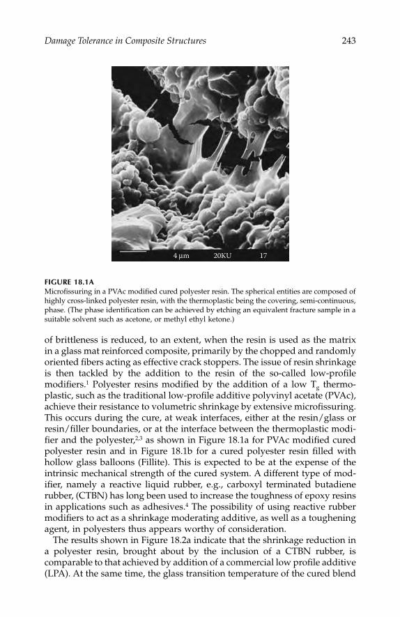
Damage Tolerance in Composite Structures
243
of brittleness is reduced, to an extent, when the resin is used as the matrixin a glass mat reinforced composite, primarily by the chopped and randomlyoriented fibers acting as effective crack stoppers. The issue of resin shrinkageis then tackled by the addition to the resin of the so-called low-profilemodifiers.
1
Polyester resins modified by the addition of a low T
g
thermo-plastic, such as the traditional low-profile additive polyvinyl acetate (PVAc),achieve their resistance to volumetric shrinkage by extensive microfissuring.This occurs during the cure, at weak interfaces, either at the resin/glass orresin/filler boundaries, or at the interface between the thermoplastic modi-fier and the polyester,
2,3
as shown in Figure 18.1a for PVAc modified curedpolyester resin and in Figure 18.1b for a cured polyester resin filled withhollow glass balloons (Fillite). This is expected to be at the expense of theintrinsic mechanical strength of the cured system. A different type of mod-ifier, namely a reactive liquid rubber, e.g., carboxyl terminated butadienerubber, (CTBN) has long been used to increase the toughness of epoxy resinsin applications such as adhesives.
4
The possibility of using reactive rubbermodifiers to act as a shrinkage moderating additive, as well as a tougheningagent, in polyesters thus appears worthy of consideration.
The results shown in Figure 18.2a indicate that the shrinkage reduction ina polyester resin, brought about by the inclusion of a CTBN rubber, iscomparable to that achieved by addition of a commercial low profile additive(LPA). At the same time, the glass transition temperature of the cured blend
FIGURE 18.1A
Microfissuring in a PVAc modified cured polyester resin. The spherical entities are composed ofhighly cross-linked polyester resin, with the thermoplastic being the covering, semi-continuous,phase. (The phase identification can be achieved by etching an equivalent fracture sample in asuitable solvent such as acetone, or methyl ethyl ketone.)
4 µm 20KU 17
IP155_C018.fm Page 243 Tuesday, January 8, 2008 12:14 PM

244
Automotive Engineering: Lightweight, Functional, and Novel Materials
is enhanced by the addition of the CTBN. Figure 18.2b gives results offracture tests on cured samples of the same polyester resin, with and withoutthe addition of Fillite particles, for two different grades of CTBN rubber. TheCTBN 1 is Hycar CTBN X8 grade, while CTBN 2 is the more polar HycarCTBN X31 grade. The results show the expected toughening effect of thereactive rubber on the polyester resin alone. The toughening actions of the
FIGURE 18.1B
Scanning electron micrograph of a fracture surface of a cured low-profile polyester resin filledwith hollow glass micro-balloons (Fillite). (Average thickness of the glass wall of the fillerparticle in the bottom right-hand corner is 5
µ
m.)
FIGURE 18.2A
Dependence of the linear shrinkage
α
and the glass transition temperature T
g
of a polyesterresin upon the type and amount of modifier (expressed in parts per hundred parts or resin, byweight).
60
80
100
120
140
0 10 15 20Amount of modifier (phr)
Tg (°
C)
1
1.5
2
2.5
3
3.5
4
4.5
Line
ar sh
rinka
ge (%
)
CTBN-Tg LPA-Tg
CTBN-Shrinkage LPA-Shrinkage
5
IP155_C018.fm Page 244 Tuesday, January 8, 2008 12:14 PM
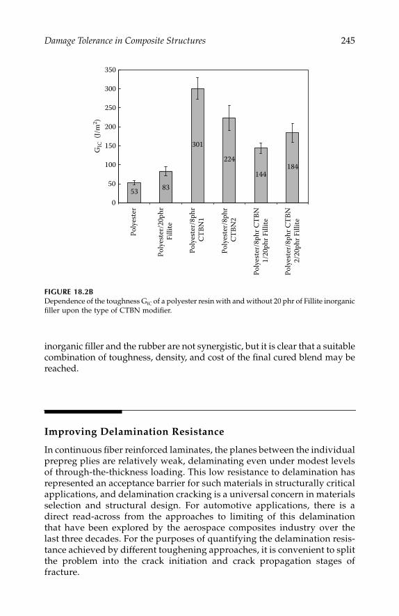
Damage Tolerance in Composite Structures
245
inorganic filler and the rubber are not synergistic, but it is clear that a suitablecombination of toughness, density, and cost of the final cured blend may bereached.
Improving Delamination Resistance
In continuous fiber reinforced laminates, the planes between the individualprepreg plies are relatively weak, delaminating even under modest levelsof through-the-thickness loading. This low resistance to delamination hasrepresented an acceptance barrier for such materials in structurally criticalapplications, and delamination cracking is a universal concern in materialsselection and structural design. For automotive applications, there is adirect read-across from the approaches to limiting of this delaminationthat have been explored by the aerospace composites industry over thelast three decades. For the purposes of quantifying the delamination resis-tance achieved by different toughening approaches, it is convenient to splitthe problem into the crack initiation and crack propagation stages offracture.
FIGURE 18.2B
Dependence of the toughness G
IC
of a polyester resin with and without 20 phr of Fillite inorganicfiller upon the type of CTBN modifier.
53 83
301
224
144184
0
50
100
150
200
250
300
350
GIC
(J/m
2 )
Poly
este
r
Poly
este
r/20
phr
Filli
te
Poly
este
r/8p
hr C
TBN
1
Poly
este
r/8p
hr
CTBN
2
Poly
este
r/8p
hr C
TBN
1/2
0phr
Fill
ite
Poly
este
r/8p
hr C
TBN
2/
20ph
r Fill
ite
IP155_C018.fm Page 245 Tuesday, January 8, 2008 12:14 PM
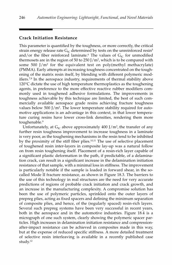
246
Automotive Engineering: Lightweight, Functional, and Novel Materials
Crack Initiation Resistance
This parameter is quantified by the toughness, or more correctly, the criticalstrain energy release rate G
IC
determined by tests on the unreinforced resin
5
and/or the fiber reinforced laminate.
6
The values of G
IC
for unmodifiedthermosets are in the region of 50 to 250 J/m
2
, which is to be compared withsome 500 J/m
2
for the equivalent test on poly(methyl methacrylate)(PMMA). Early attempts at increasing toughness concentrated on the tough-ening of the matrix resin itself, by blending with different polymeric mod-ifiers.
7,8
In the aerospace industry, requirements of thermal stability above120°C dictate the use of high temperature thermoplastics as the tougheningagents, in preference to the more effective reactive rubber modifiers com-monly used in toughened adhesive formulations. The improvements intoughness achievable by this technique are limited, the best of such com-mercially available aerospace grade resins achieving fracture toughnessvalues below 500 J/m
2
. The lower temperature stability required for auto-motive applications is an advantage in this context, in that lower tempera-ture curing resins have lower cross-link densities, rendering them moretoughenable.
9
Unfortunately, at G
IC
above approximately 400 J/m
2
,
the transfer of anyfurther resin toughness improvement to increase toughness in a laminateis very poor, as the toughening mechanisms in the resin tend to be inhibitedby the proximity of the stiff fiber plies.
10,11
The use of selective placementof toughened resin inter-layers in composite lay-up was a natural followon from resin toughening itself. Placement of a resin-rich layer capable ofa significant plastic deformation in the path, if predictable, of a delamina-tion crack, can result in a significant increase in the delamination initiationresistance of that sample, with a minimal loss in stiffness. The improvementis particularly notable if the sample is loaded in forward shear, in the so-called Mode II fracture resistance, as shown in Figure 18.3. The barriers tothe use of this technology in real structures are the need for very accuratepredictions of regions of probable crack initiation and crack growth, andan increase in the manufacturing complexity. A compromise solution hasbeen the use of polymeric particles, sprinkled onto the outer layers ofprepreg plies, acting as fixed spacers and defining the minimum separationof composite plies, and hence, of the (regularly spaced) resin-rich layers.Several such prepreg systems have been very successful in recent years,both in the aerospace and in the automotive industries. Figure 18.4 is amicrograph of one such system, clearly showing the polymeric spacer par-ticles. High increases in delamination initiation resistance and compression-after-impact resistance can be achieved in composites made in this way,but at the expense of reduced specific stiffness. A more detailed treatmentof selective resin interleaving is available in a recently published casestudy.
12
IP155_C018.fm Page 246 Tuesday, January 8, 2008 12:14 PM
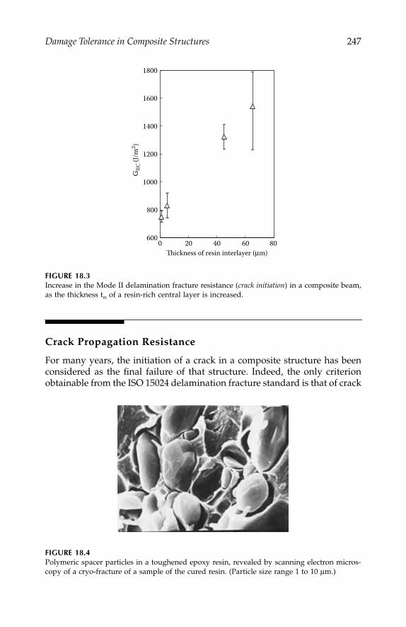
Damage Tolerance in Composite Structures
247
Crack Propagation Resistance
For many years, the initiation of a crack in a composite structure has beenconsidered as the final failure of that structure. Indeed, the only criterionobtainable from the ISO 15024 delamination fracture standard is that of crack
FIGURE 18.3
Increase in the Mode II delamination fracture resistance (
crack initiation
) in a composite beam,as the thickness t
m
of a resin-rich central layer is increased.
FIGURE 18.4
Polymeric spacer particles in a toughened epoxy resin, revealed by scanning electron micros-copy of a cryo-fracture of a sample of the cured resin. (Particle size range 1 to 10
µ
m.)
600
800
1000
1200
1400
1600
1800
0 20 40 60 80Thickness of resin interlayer (µm)
GIIC
(J/m
2 )
IP155_C018.fm Page 247 Tuesday, January 8, 2008 12:14 PM
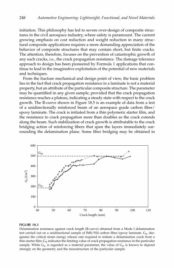
248
Automotive Engineering: Lightweight, Functional, and Novel Materials
initiation. This philosophy has led to severe over-design of composite struc-tures in the civil aerospace industry, where safety is paramount. The currentgrowing emphasis on cost reduction and weight reduction in many struc-tural composite applications requires a more demanding appreciation of thebehavior of composite structures that may contain short, but finite cracks.The attention, therefore, focuses on the prevention of catastrophic growth ofany such cracks, i.e., the crack propagation resistance. The damage toleranceapproach to design has been pioneered by Formula 1 applications that con-tinue to lead in the imaginative exploitation of the potential of new materialsand techniques.
From the fracture mechanical and design point of view, the basic problemlies in the fact that crack propagation resistance in a laminate is not a materialproperty, but an attribute of the particular composite structure. The parametermay be quantified in any given sample, provided that the crack propagationresistance reaches a plateau, indicating a steady state with respect to the crackgrowth. The R-curve shown in Figure 18.5 is an example of data from a testof a unidirectionally reinforced beam of an aerospace grade carbon fiber/epoxy laminate. The crack is initiated from a thin polymeric starter film, andthe resistance to crack propagation more than doubles as the crack extendsalong the beam. Such stabilization of crack growth is attributable to the crackbridging action of reinforcing fibers that span the layers immediately sur-rounding the delamination plane. Some fiber bridging may be obtained in
FIGURE 18.5
Delamination resistance against crack length (R-curve) obtained from a Mode I delaminationtest carried out on a unidirectional sample of IMS/924 carbon fiber/epoxy laminate. G
IC
des-ignates the critical strain energy release rate required to initiate a delamination crack from athin starter film; G
IP
indicates the limiting value of crack propagation resistance in the particularsample. While G
IC
is regarded as a material parameter, the value of G
IP
is known to dependstrongly on the geometry and the mesostructure of the particular sample.
0
100
200
300
400
500
600
40 50 60 70 80 90 100 110Crack length (mm)
GI (
J/m2 )
GIC
GIP
IP155_C018.fm Page 248 Tuesday, January 8, 2008 12:14 PM

Damage Tolerance in Composite Structures
249
any laminate from misaligned and nested reinforcing fibers and tows, but itis now generally agreed that the most effective way of delaying, or evenpreventing, delamination failures is by the use of deliberately introducedz-direction (through-the-thickness) reinforcement. Stitching with thin syn-thetic fibers was the first such technique to be explored. Very significantimprovements in damage resistance of woven fabric composites wereachieved, for a limited loss in the in-plane properties of the composites.
13,14
Tufting is the most recent version of this technology: a loop of tufting threadis introduced into the fibrous preform by a tufting needle; the needle extractedfollowing the same path, is then moved to the next predetermined position,and the process is repeated.
15
The process relies on the friction between thethread and the fibrous preform to keep the tufts in position; once a successfulmatch is achieved, the procedure is highly suited to automation. Figure 18.6shows a tufting head installed on a robot arm in the author’s laboratory, anda more detailed photograph of the needle/thread arrangement.
The two-sided or single-sided stitching technique is seen to be mostapplicable as a global reinforcement for flat panels, or a more local rein-forcement for more complex fiber preforms. The composite structure is thenachieved by liquid resin filling of the preform and out-of-autoclave cure. Itis not really feasible to use any form of stitching with prepreg-based com-posites, as two-sided access to the lay-up is required, and the resin present
FIGURE 18.6
Tufting head (KSL
15
) installed on a Kawasaki robot arm (left) and detail of the tufting needleand thread arrangement (right).
IP155_C018.fm Page 249 Tuesday, January 8, 2008 12:14 PM

250
Automotive Engineering: Lightweight, Functional, and Novel Materials
in the prepreg fouls the stitching needle. The most recently introducedthrough-the-thickness reinforcement technique of Z-Fiber
®
pinning (Z-pin-ning) overcomes this problem.
16–18
The stiff Z-Fibers
®
, hereafter referred toas Z-pins, are inserted orthogonally to the plane of the composite pliesduring the manufacturing process, before the resin matrix is cured, effec-tively pinning the individual layers together. The Z-pins can be made ofmetal, glass, or even ceramic, but their most convenient form for applica-tions of the type considered here is as fully cured carbon fiber rods with anepoxy of bismaleimide matrix resin. The insertion into the
uncured
laminatelay-up is assisted by ultrasonic vibrations, as shown in Figure 18.7, andrequires one-sided, on-mould access, resulting in much less damage tothe fibers in the composite plies than stitching. Figure 18.8 shows how theZ-pins, pulling out from the composite under predominantly Mode I load-ing, stabilize the failure in a composite structural element, namely a T-jointsubjected to a stiffener pull-off test.
This new technology is envisaged to be used as selective reinforcement,and has already been utilized to provide urgently needed solutions toincreased load-bearing capacity regulations for several Formula 1 racingteams,
19
as well as answering significant structural integrity challenges inthe case of military jets. The increase in the crack propagation resistanceof laminates, offered by Z-pinning, is an order of magnitude higher thanthat obtainable by use of toughened resins.
20
Preliminary impact damagestudies suggest that the Z-pins are not effective in preventing the earlyinitiation of delamination cracking, but are highly effective in reducing andstopping subsequent crack growth. Thus, the most damage tolerant com-posite structures of the future might be obtained by a combination of
FIGURE 18.7
Schematic of the Z-pinning process: The Z-Fiber
®
preform is located on top of the uncuredlaminate, directly above the area to be reinforced. The Z-Fibers
®
are inserted into the laminatesby the actions of the ultrasonic horn. During insertion the low-density foam holding the pinsis crushed. The pins are shear cut at the surface of the laminate and the excess pin length andthe remaining foam are discarded.
Ultrasonic horn
Z-Fibers
Cutter
Laminate
Z-Fiber preform
IP155_C018.fm Page 250 Tuesday, January 8, 2008 12:14 PM

Damage Tolerance in Composite Structures
251
selectively placed crack initiation resistant resin layers with Z-pinned crackstopping regions.
References
1. Pattison, V. A., R. R. Hindersinn, and W. T. Schwartz,
J. Appl. Plym. Sci
., No.18, 2763, 1974.
2. Bucknall, C. B., I. K. Partridge, and M. J. Phillips,
Polymer
, No. 32, 636–640, 1991.3. Li, W., and L. J. Lee,
Polymer
, No. 39, 5677–5687, 1998.4. Kinloch, A. J.,
Structural Adhesives: Developments in Resins and Primers
, A. J.Kinloch, ed., Elsevier Applied Science Publishers, London, 127–162, 1986.
5. ISO 13586
Determination of Fracture Toughness (Gc & Kc) for Plastics
.6. ISO 15024
Determination of Mode I (Critical Strain Energy Release Rate or FractureToughness, GIC) of Unidirectional Fibre-Reinforced Polymer Laminates Using theDouble Cantilever Beam (DCB) Specimen
.
FIGURE 18.8
Progressive failure in a T-pull off test of a composite T-joint, reinforced by localized Z-pinningin the stiffener foot region. The vertical displacements are 0.05, 0.13, 0.62, and 3.39 mm, goingfrom (a) to (d). It should be noted that the equivalent, but unpinned, joint failed catastrophicallyat vertical cross-head displacement of 0.13 mm (b). In (d) the carbon fiber Z-pins pulled out ofthe stiffener foot are visible. (The vertical lines marked on the side of the specimen are forpurposes of crack length determination only.)
A B
C D
IP155_C018.fm Page 251 Tuesday, January 8, 2008 12:14 PM
252
Automotive Engineering: Lightweight, Functional, and Novel Materials
7. Bucknall, C.B., and I. K. Partridge,
Polymer
, Vol. 24, 639–644, 1983.8. Pascault, J.-P., and R. J. J. Williams, “Formulation and Characterization of
Thermoset-Thermoplastic Blends,”
Polymer Blends
, Vol. 1, Chapter 13, D. R.Paul and C. B. Bucknall, eds., John Wiley & Sons, 2000.
9. Yee, A.F., and R. A. Pearson,
NASA Contractor Report
, p.
3718, 1983, and 3852,1984.
10. Hunston, D. L.,
ASTM Composites Technology Review
, Vol. 6, 176, 1984.11. Bradley, W. L., “Relationship of matrix toughness to interlaminar fracture tough-
ness,”
Application of Fracture Mechanics to Composite Materials
, Chapter 5, K.Friedrich, ed., Elsevier, 1989.
12. Partridge, I. K., and D. D. R. Cartié, “Suppression of initiation of delaminationcracking in unidirectional composites by self-same resin interleaving,”
Theapplication of fracture mechanics to polymers, adhesives, and composites,
D. R. Moore,ed., ESIS Publication 33, ISBN 0 08 044205 6, Elsevier Applied Science Publish-ers, London, 2003.
13. Dransfield, K. A., L. K. Jain, and Y.-W. Mai,
Comps. Sci. & Tech
., Vol. 58, 815–827and 829–837, 1998.
14. Mouritz, A. P., K. H. Leong, and I. Herszberg,
Composites: Part A
, Vol. 28A,979–991, 1999.
15. KSL GmbH, website: http://www.ksl-lorsch.de.16. Tong, L., A. P. Mouritz, and M. Bannister, eds.,
3D Fibre Reinforced PolymerComposites
, Elsevier Science, ISBN 008 043938-1, 2002.17. http//:www.aztex-z-fiber.com.18. Partridge, I. K., D. D. R. Cartié, and T. Bonnington, “Manufacture and perfor-
mance of Z-pinned composites,”
Advanced Polymeric Materials: Structure-PropertyRelationships
, Chapter 5, S. Advani, and G. Shonaike, eds., CRC Press, BocaRaton, FL April 2003.
19. “Safety pins,”
Journal of Racecar Engineering
, 56–62, December 2002.20. Cartié, D. D. R., and I. K. Partridge, “Delamination behaviour of Z-pinned
laminates,”
Proceedings of 2nd ESIS TC4 conference
, (Les Diablerets, Switzerland,13–15 September 1999), J. G. Williams and A. Pavan, eds., Elsevier, ESIS Pub-lication 27, ISBN 008 043710-9, 2000.
IP155_C018.fm Page 252 Tuesday, January 8, 2008 12:14 PM

253
19
High-Performance Autosport Surface
Treatments and Composites
Roger Davidson, Ed Allnutt, and Will Battrick
CONTENTS
Lightweight Materials Options ........................................................................253Surface Engineering of Light Alloys ...............................................................254Keronite™ Hard Ceramic Surfacing for Light Alloys ..................................254
Keronite Process.........................................................................................255Coating Structure.......................................................................................257Keronite Composites .................................................................................257Applications................................................................................................258
Polymer Composites ..........................................................................................260Highly Stressed Composites .............................................................................260Light-Weight Pressure Vessels ..........................................................................263Conclusions..........................................................................................................265
Lightweight Materials Options
In the automotive sector, the wider use of light alloy materials such asaluminum and magnesium, and structural composites offers an undeniablyattractive means of gaining greater performance with increased fuel econ-omy and reduced emissions. Within the realm of autosport, the desire tominimize weight is even more pressing—those involved in engineering thecars and bikes that compete every week strive to utilize high-specific strengthand stiffness materials in as many areas as possible. This chapter will con-sider the use of environmentally friendly enhanced surface treatments onlight alloys, as well as some specific applications for highly stressed light-weight composite components.
IP155_C019.fm Page 253 Monday, December 31, 2007 5:05 PM
254
Automotive Engineering: Lightweight, Functional, and Novel Materials
Surface Engineering of Light Alloys
Until recently, the widespread use of light alloys in autosport has beenhindered by the surface performance of these materials. This is in contrastto their specific bulk properties, which have been improved to the stagewhere they surpass their ferrous competitors. With its very low specificgravity of ~1.8, magnesium alloys are particularly attractive.
Applications for magnesium alloys have been limited by their reputationfor susceptibility to corrosion. In fact, degradation of magnesium is closelyrelated to its purity with respect to contaminants such as copper, nickel, andiron. Close purity control can give magnesium components salt spray cor-rosion behavior better than many aluminum alloys.
In recent times, the metallurgy of the magnesium system has been subjectto a great deal of improvement, and many new and potentially beneficialsurface modification technologies have begun to reach commercialization.These have brought enhancements to corrosion behavior, tribology, and aestheticappearance, while simultaneously overcoming the environmental restric-tions of the early systems.
The most recent developments, centered on the phenomenon of plasmaelectrolytic oxidation (PEO), offer exceptional performance enhancementscombined with an opportunity to develop exotic surfaces through second-phase infiltration. Plasma electrolysis is a relatively new electrochemicaltreatment process/discipline. The most important derivative is plasmaelectrolytic deposition (PED), which includes plasma electrolytic otidationand plasma electrolytic saturation (PES). In plasma electrolytic deposi-tion, spark or arc plasma micro-discharges in an aqueous solution areutilized to ionize gaseous media from the solution, such that complexcompounds are synthesized on the metal surface through the plasma chem-ical reactions.
Keronite™ Hard Ceramic Surfacing for Light Alloys
Keronite ceramic surfacing for aluminum, magnesium, and titanium alloysis a new environmentally friendly electrolytic conversion coating that effec-tively substitutes traditionally more hazardous processes, such as anodizingand chromating.
Keronite is a corrosion resistant, hard (400–1900 HV) oxide of the substratematerial. Keronite thickness ranges from 5 to 150 microns. The layer is pre-dictable, uniform, and well bonded with the metal substrate. High hardnessand toughness of the Keronite surface enables aluminum and magnesiumalloys to be used in new applications. The process was developed and com-mercialized by Keronite Limited, United Kingdom. Crompton Technology
IP155_C019.fm Page 254 Monday, December 31, 2007 5:05 PM

High-Performance Autosport Surface Treatments and Composites
255
Group (CTG) has a manufacturing licence and has been developing theprocess and assessing treated components in a number of automotive andother industrial applications.
Keronite Process
Ceramic layers produced on aluminum, magnesium, and titanium by a novelplasma electrolytic oxidation technology offer an attractive alternative tochromating, hard anodized, and conversion coatings in wear-resistant andcorrosion-resistant applications. Composite and multilayer coatings incor-porating lubricious or additional hard phases can also be produced. Likeanodizing, the process uses an electric power supply and a bath, but it issignificantly different from anodizing because it produces harder and thickerlayers while using ecologically compatible alkali electrolytes, and a speciallymodulated AC power supply.
Preparation for the Keronite coating process requires only de-greasing ofthe part. No special pre-treatment of the surface is required because theKeronite process makes use of electric micro-discharges in the electrolytethat cleans the surface. Coating usually takes 10
–
60 minutes depending onthe required thickness. The coating grows at the interface, and dependingon the relative density of the base alloy to the oxide layer, the specimendimensions are increased. After treatment, the part is rinsed in warm waterfor several minutes. The low concentrated alkali electrolyte does not containany toxic or aggressive elements and is no more hazardous than water in awashing machine. Figure 19.1 shows the Keronite coating apparatus.
FIGURE 19.1
Keronite coating apparatus.
IP155_C019.fm Page 255 Monday, December 31, 2007 5:05 PM

256
Automotive Engineering: Lightweight, Functional, and Novel Materials
Typical features of the Keronite coatings are described below:
Extremely hard and wear-resistant:
hardness ranges from 350 to 600 HV(Rc
=
36
−
55) on magnesium and 600–1900 HV on aluminum. In twobody abrasive wear situations, Keronite reduced the wear rate ofuncoated magnesium alloys by a factor of 20 an aluminum alloys by~100.
Low-friction:
once polished, the coating has a friction coefficient ofless than 0.15 (against steel). Keronite can eliminate the high frictionand galling normally associated with magnesium.
Corrosion resistance:
outdoor tests show months without corrosion.
Coating thickness:
thicknesses from 10 µm to 80
μ
m provide a uni-form surface layer.
High dielectric strength:
the coatings withstand in excess of 1000 VDC, and are therefore well-suited as surfaces for electrical com-ponents.
Heat resistance:
the coatings can typically withstand short exposuresof up to 1000ºC.
In wear-resistant applications, Keronite coatings can be used at thicknessesup to ~150 µm on aluminum and titanium alloys, and ~80 µm on magnesiumalloys, and layers 200–600 µm in thickness can be produced where corrosionresistance or electrical insulation is the main requirement. The process allowsa uniform layer to be formed on complex shapes without cracking, and littlesurface preparation is required. Worn or damaged parts can be recoatedwithout stripping the damaged coating. Coating of deeper holes or boresmay require special jigging and electrodes. Best results are obtained on alu-minum alloys containing <10%Si, but—unlike with hard anodizing—otheralloying elements, such as copper, are beneficial to coating hardness and wearresistance. Best results on titanium and magnesium are obtained on alloys,rather than the pure metal. Some typical coating thicknesses and hardnessesare given in Table 19.1, although microhardness levels up to 1900 HV havebeen achieved on 2xxx series aluminum alloys.
TABLE 19.1
Properties of Typical Keronite Coatings on Various Alloys
Alloy Thickness (µm)Microhardness,
HV (100 g)
AA 6082 25–250 1250 A 7075 25–200 1350 A 2024 25–150 1550 Ti 6-4-1 10–100 500 Mg AZ91 5–50 350
IP155_C019.fm Page 256 Monday, December 31, 2007 5:05 PM

High-Performance Autosport Surface Treatments and Composites
257
Coating Structure
The Keronite layer is the complex oxide ceramic consisting of hard crystallinephases dislocated in the matrix of softer phases of oxide. Such structuralcomposition provides Keronite with a combination of high hardness, wearresistance, and shock resistance. These attributes explain the higher flexibil-ity of Keronite, as well as nearly three times less reduction of basic materialfatigue strength compared with anodizing.
Keronite coating porosity gradually decreases with depth. The porosity is amaximum at the surface of 15%–30% and is characterized by the pores oftypical microns. The ceramic layer close to metal substrate is much less porousat 2%
–
10%. The porosity can be controlled by the AC voltages applied duringthe treatment process. Unlike anodized surfaces, Keronite porosity is randomlydistributed throughout. The graded structure of porosity can enable subse-quent impregnation of the Keronite surface with a variety of materials, suchas paints, organic materials, metals, carbides, and even diamond-like carbon.
The Keronite process involves conversion and enrichment of the surfaceregion, rather than deposition of a new layer. Because the coating is formedthrough a reaction that involves the substrate, adhesion is excellent. Surfacegrowth is approximately 30% of the coating thickness. As deposited, thecoating consists of a thin transitional layer between substrate and coating,a compact, layer with low porosity, and an outer layer characterized byhigher (>15%) porosity. For some applications, the outer layer should beground or polished away, but the porosity can provide keying for furtherlayers applied to optimize performance. Secondary treatments include coat-ing with PTFE to reduce friction, polymer sealants to increase corrosionresistance, and impregnation with nickel, chromium, copper, or carbides.
Ball on disc tests have shown that the adhesive wear resistance of Keroniteon aluminum alloys, particularly 2024, is superior to that of hard chromiumlayers, and an order of magnitude better than hard anodizing or electrolessnickel coatings. Coated 6082 aluminum alloy has survived over 2000 h in saltspray tests, but high copper containing alloys perform less well (200 h),although their performance can be improved by polymer sealing. The coatingsexhibit good thermal resistance, and coatings can withstand short exposuresup to 2000ºC, which makes them ideal for parts, such as rocket venturi, andprolonged exposure to high temperatures has no adverse effect on the coatingperformance, other than some crazing of the surface. Keronite layers alsoprovide suitable substrates for mounting electrical components. Breakdownvoltages are typically 10 V
μ
m
−
1
, and can be increased further by impregnation.
Keronite Composites
The Keronite surface can be used as a matrix for composite coatings. Twocoating systems can be used in conjunction, in order to create superiorproperties for the combined coating. External coating partly penetrates theporous surface of Keronite and partly remains on the surface. The penetrated
IP155_C019.fm Page 257 Monday, December 31, 2007 5:05 PM
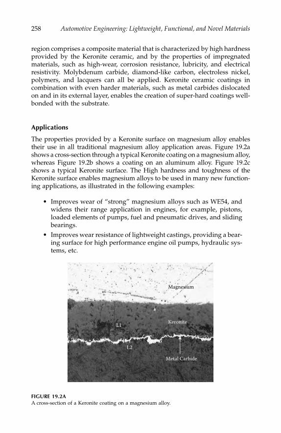
258
Automotive Engineering: Lightweight, Functional, and Novel Materials
region comprises a composite material that is characterized by high hardnessprovided by the Keronite ceramic, and by the properties of impregnatedmaterials, such as high-wear, corrosion resistance, lubricity, and electricalresistivity. Molybdenum carbide, diamond-like carbon, electroless nickel,polymers, and lacquers can all be applied. Keronite ceramic coatings incombination with even harder materials, such as metal carbides dislocatedon and in its external layer, enables the creation of super-hard coatings well-bonded with the substrate.
Applications
The properties provided by a Keronite surface on magnesium alloy enablestheir use in all traditional magnesium alloy application areas. Figure 19.2ashows a cross-section through a typical Keronite coating on a magnesium alloy,whereas Figure 19.2b shows a coating on an aluminum alloy. Figure 19.2cshows a typical Keronite surface. The High hardness and toughness of theKeronite surface enables magnesium alloys to be used in many new function-ing applications, as illustrated in the following examples:
• Improves wear of “strong” magnesium alloys such as WE54, andwidens their range application in engines, for example, pistons,loaded elements of pumps, fuel and pneumatic drives, and slidingbearings.
• Improves wear resistance of lightweight castings, providing a bear-ing surface for high performance engine oil pumps, hydraulic sys-tems, etc.
FIGURE 19.2A
A cross-section of a Keronite coating on a magnesium alloy.
Magnesium
Keronite
Metal Carbide
L1
L2
IP155_C019.fm Page 258 Monday, December 31, 2007 5:05 PM

High-Performance Autosport Surface Treatments and Composites
259
• Stiffens ultra-thin alloy sections and fabrications, improves corro-sion protection, for example, covers, housings, pressure die-casting,and manifolds.
• In electronic applications, Keronite provides a hard, scratch-resis-tant undercoat for paint or lacquer, and can be used for mobilephones, lap-tops, camcorders, and camera applications.
• Some coating technologies, such as plasma spraying, may resultin degradation to the underlying component. The application ofKeronite as a thermal barrier and abrasion resistant treatment for
FIGURE 19.2B
A cross-section of a Keronite coating on an aluminum alloy.
FIGURE 19.2C
A typical surface of a Keronite coating.
IP155_C019.fm Page 259 Monday, December 31, 2007 5:05 PM

260
Automotive Engineering: Lightweight, Functional, and Novel Materials
racing pistons may provide a performance advantage because ofgreater adherence, and improved thermal performance with acorresponding knock-on reduction in the required cooling systemcapacity. There can also be a reduction in carbon build-up inpiston applications; a reduction in thermal load on the piston,which in turn, allows a reduction in piston size through improvedmaterials properties at lower temperatures. Non-autosport appli-cations in pistons are likely in the treatment of aluminum alloydiesel pistons where piston design can be enhanced by the useof Keronite coatings.
Polymer Composites
Polymer-based composites with carbon and glass fibers have been usedin automotive applications for lightweight body panels. However, mate-rials and manufacturing costs and, more recently, disposal and recycling,have restricted their greater use. Nonetheless, one area that has beenreceiving more interest recently has been the use of natural fiber reinforcedcomposites designed for biodegradability at end of life. These materialswill be even more attractive once they have been combined with bio-degradable, but environmentally stable, natural polymer-based matrices.At the end of their life, these systems degrade when composted. Thesetypes of systems will not be considered further in this chapter, but insteadthe focus will be turned on much more mature highly stressed compositesused in motorsport.
Highly Stressed Composites
Propellor shafts (or prop-shafts) take power from the engine to the gearboxand are used in motorsport applications worldwide. CTG’s compositeTORQline
™
range of prop-shafts have helped teams to achieve success at LeMans, in FIA GT, ALMS, and other series. The approach to the productionof prop-shafts begins with the design of the optimized composite tube ele-ment. Each tube is a bespoke design for the application, and is manufacturedby filament winding, or in some cases, tube rolling. These hybrid tubes aredesigned in conjunction with the end fittings, and bond to ensure that theywork together to give the strongest and most reliable solution. Options forcouplings include composite discs, tripodes, and Hooke’s joints.
The basic attraction of composite materials for prop-shafts (or any longdriveshaft application) is that they make it possible to increase the criticalspeed or bending resonant frequency
f
c
of the shaft according to:
IP155_C019.fm Page 260 Monday, December 31, 2007 5:05 PM

High-Performance Autosport Surface Treatments and Composites
261
(19.1)
If the length
L
that the shaft needs to span is fixed, and the diameter
d
isrestricted, then the only way of improving the critical speed is to increasethe modulus
E
divided by density
ρ
(the specific modulus
E/
ρ
)
. The mosteffective way of improving the specific modulus is to use carbon fiber com-posite, and this enables dramatically longer and lower weight single-piecedriveshafts to be produced. For very long shafts, low angle, high stiffnesspitch fibers can be incorporated to increase the whirling speed. Higher anglefibers react the torque and increase torsional buckling resistance. Typicalproperties are given in Table 19.2.
Composite torque transmission shafts offer significant weight savings overmore traditional materials without any decrease in mechanical properties.The reduction in mass has a direct impact on the force required to accelerate/decelerate the vehicle.
The advantages of using composite prop-shafts may include:
•
Light weight.
Typical weight savings of up to 50%. This reducesthe overall kerb weight of the vehicle and, therefore, the forcerequired to accelerate and decelerate.
•
Low mass moment of inertia.
This is a measure of the rotationalinertia of a part, and its resistance to change in rotational velocity.Due to the low density and high mechanical properties of carbonfiber reinforced polymer prop-shafts, the moment of inertia is sig-nificantly less than steel prop-shafts, improving the overall vehicleperformance.
•
Whirl elimination.
Due to their low cross-sectional area and mass,and high longitudinal stiffness, composite prop-shafts have higherwhirling frequencies than other materials. This allows compositeprop-shafts to span large lengths at high speeds. CTG has experi-ence of supplying single-part prop-shafts to replace directly two-part shafts, offering significant weight savings and eliminating theuse of a center bearing.
TABLE 19.2
Typical Prop-Shaft Properties
Property of the Prop-Shaft Value
Weight 2.0 kgLength 1.5 mDiameter range 58.5 to 75 mmTemperature range
<
120
°
C peak,
<
100
°
C operatingFailure torque 3500 NmFatigue life
>
10
6
Cycles @ 85% failure torque
f kdL
Ec = 2 ρ
IP155_C019.fm Page 261 Monday, December 31, 2007 5:05 PM
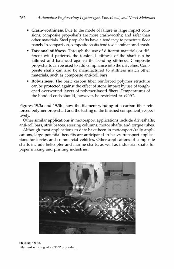
262
Automotive Engineering: Lightweight, Functional, and Novel Materials
•
Crash-worthiness.
Due to the mode of failure in large impact colli-sions, composite prop-shafts are more crash-worthy, and safer thanother materials. Steel prop-shafts have a tendency to penetrate floorpanels. In comparison, composite shafts tend to delaminate and crush.
•
Torsional stiffness.
Through the use of different materials or dif-ferent wind patterns, the torsional stiffness of the shaft can betailored and balanced against the bending stiffness. Compositeprop-shafts can be used to add compliance into the driveline. Com-posite shafts can also be manufactured to stiffness match othermaterials, such as composite anti-roll bars.
•
Robustness.
The basic carbon fiber reinforced polymer structurecan be protected against the effect of stone impact by use of tough-ened overwound layers of polymer-based fibers. Temperatures ofthe bonded ends should, however, be restricted to
<
90
°
C.
Figures 19.3a and 19.3b show the filament winding of a carbon fiber rein-forced polymer prop-shaft and the testing of the finished component, respec-tively.
Other similar applications in motorsport applications include driveshafts,anti-roll bars, strut braces, steering columns, motor shafts, and torque tubes.
Although most applications to date have been in motorsport/rally appli-cations, large potential benefits are anticipated in heavy transport applica-tions for lorries and commercial vehicles. Other applications of compositeshafts include helicopter and marine shafts, as well as industrial shafts forpaper making and printing industries.
FIGURE 19.3A
Filament winding of a CFRP prop-shaft.
IP155_C019.fm Page 262 Monday, December 31, 2007 5:05 PM

High-Performance Autosport Surface Treatments and Composites
263
Driveshafts transfer the torque to the wheels and
a system has beendeveloped for the production of carbon fiber reinforced driveshafts thatcan have either Tripode end fittings integrated into the structure, or splinedend fittings. A shaft of typically 35 mm can be used to transmit a torqueof > 3000 Nm, and offers a weight saving of 40%–50%. Each shaft isdesigned to meet each application in order to give maximum benefit toeach customer.
Light-Weight Pressure Vessels
Another potentially very important application for highly stressed compos-ites is in lightweight pressure vessels and accumulators for the storage ofgases and fuels. CTG’s experience in pressure vessel design and manufactureranges from small pressure vessels of volume 200–700 cc for use as nitrogenvessels for F1 valve train applications to large vessels of 400 mm diameterand 1500 mm length for sub-sea applications to depths of over 4000 m, aswell as large spheres for storage of oxygen pressurant. Most vessels requirea metallic or polymer liner.
A new dynamic liner technology has been developed that gives thesetypes of vessels exceptional fatigue resistance, allowing both low shapeprofile reservoirs and accumulators for active systems to be produced. Thesevessels offer a versatile design, high strength, low weight, and excellent
FIGURE 19.3B
Testing of assembled CFRP prop-shaft.
IP155_C019.fm Page 263 Monday, December 31, 2007 5:05 PM
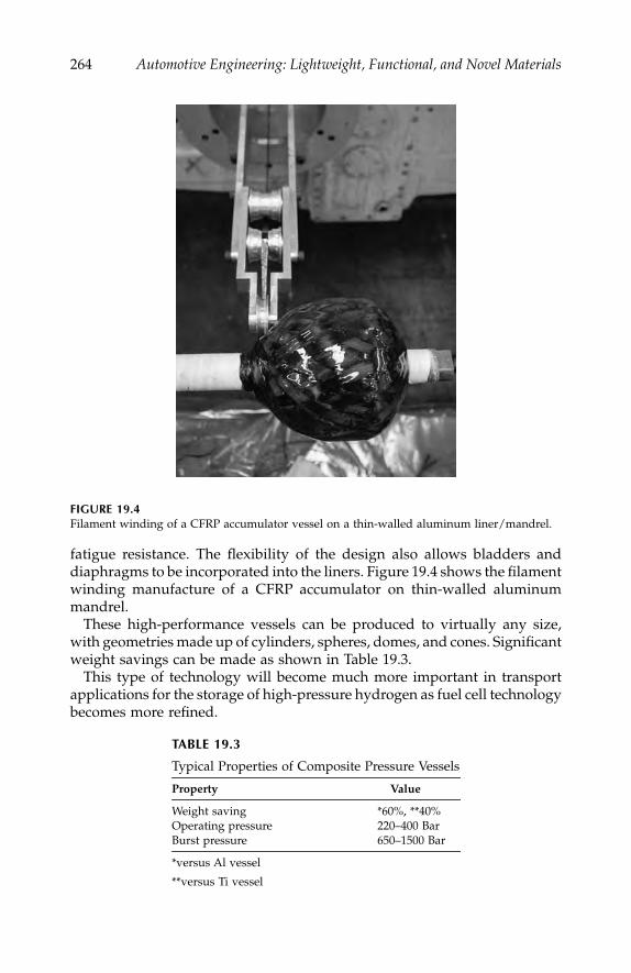
264
Automotive Engineering: Lightweight, Functional, and Novel Materials
fatigue resistance. The flexibility of the design also allows bladders anddiaphragms to be incorporated into the liners. Figure 19.4 shows the filamentwinding manufacture of a CFRP accumulator on thin-walled aluminummandrel.
These high-performance vessels can be produced to virtually any size,with geometries made up of cylinders, spheres, domes, and cones. Significantweight savings can be made as shown in Table 19.3.
This type of technology will become much more important in transportapplications for the storage of high-pressure hydrogen as fuel cell technologybecomes more refined.
FIGURE 19.4
Filament winding of a CFRP accumulator vessel on a thin-walled aluminum liner/mandrel.
TABLE 19.3
Typical Properties of Composite Pressure Vessels
Property Value
Weight saving *60%, **40%Operating pressure 220–400 BarBurst pressure 650–1500 Bar
*versus Al vessel
**versus Ti vessel
IP155_C019.fm Page 264 Monday, December 31, 2007 5:05 PM

High-Performance Autosport Surface Treatments and Composites
265
Conclusions
Advanced materials and surface technologies have always played a criticalrole in the optimization of autosport vehicles. These types of technologieswill become increasingly important in the commodity automotive vehiclesector, as environmental concern and emissions reduction gain even greaterinternational priority. From a small company perspective, this chapter hasattempted to focus on some noteworthy highlights, and should help pointto directions for future collaborative efforts.
IP155_C019.fm Page 265 Monday, December 31, 2007 5:05 PM

IP155_C019.fm Page 266 Monday, December 31, 2007 5:05 PM

267
Index
A
Absorption energy, compressive tests to evaluate, 120
Accelerometers, 88, 89AdhFAST™, 189–193Aerospace composites industry, 245, 248Al alloy, heavily deformable, 133–147,
see also
Aluminum alloyAl matrix annealing, 139chemical compositions of test materials, 137cold-working operations, 137, 140elemental maps, 142, 143elongation of cast materials, 141fatigue crack initiation, 143, 144fatigue strength and crack generation,
142–143fine microstructure development, 134–135fragmentation of silicon and compounds,
138–140mesocomplex structure, 134, 136metal matrix composite, 144microstructural refinement, 141microstructures of cast materials, 138plasticity and tensile properties, 140–142prototype products, 146recovery processes, 136recyclable design for sustainable develop-
ment, 133–134problems in scrap metal recycling,
133–134upgrade recycle design for Al-Si-X
alloys, 134relationship between ultimate tensile
strength and total elongation,146repeated thermomechanical treatment,
136–138rolling direction, 138second-phase structure developed
by plastic workings, 136technological applications, 144–146tensile testing, 140true stress–true plastic strain curves, 142void formed by silicon cracking, 138
All-aluminum car, 21, 26ALPORAS closed-cell foam, 117, 118Al-Si-X cast materials, 134, 135Aluminum alloy(s),
see also
Al alloy, heavily deformable
bake-hardening properties, 24compressive properties of, 126flow stress, 127friction stir welding, 184Keronite coating on, 259nominal stress–nominal strain curves of, 127rate dependency, 68recycling properties of, 26sheets, development of, 10
Aluminum alloys, formability of, 97–108asymmetric rolling, 105calculation of
r
-value, 101correlation between
r
-value and LDR, 103–105
corrosion resistance, 98effect of crystallographic, 106evaluation of press formability, 97Goss orientation, 105limiting drawing ratio, 97, 103methods of improving formability by
texture control, 105–106orientation distribution functions, 99orientation drawing functions, 106recrystallization texture, 99, 104, 107relaxed constraints model in, 101rolling textures, 98sheet sample recrystallization texture, 104Taylor model, 100tensile properties of, 98texture of aluminum alloy sheets, 98–103texture control through warm rolling,
106, 107ways of improving
r
-value, 108Aluminum beverage cans, recovery ratio of
(Japan), 26Aluminum body panels
chemical composition of, 23forming technology, 25important properties required for, 22
IP155_C020.fm Page 267 Monday, December 31, 2007 5:08 PM
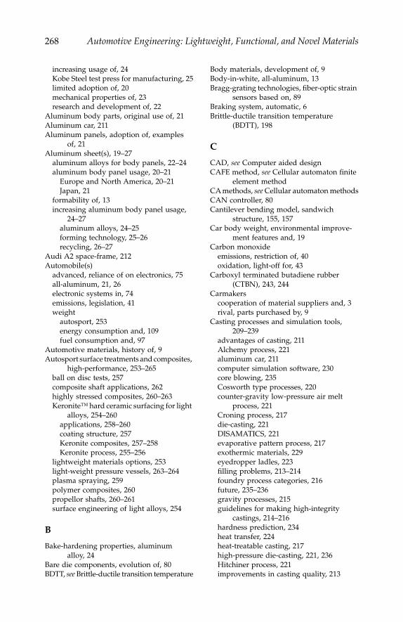
268
Automotive Engineering: Lightweight, Functional, and Novel Materials
increasing usage of, 24Kobe Steel test press for manufacturing, 25limited adoption of, 20mechanical properties of, 23research and development of, 22
Aluminum body parts, original use of, 21Aluminum car, 211Aluminum panels, adoption of, examples
of, 21Aluminum sheet(s), 19–27
aluminum alloys for body panels, 22–24aluminum body panel usage, 20–21
Europe and North America, 20–21Japan, 21
formability of, 13increasing aluminum body panel usage,
24–27aluminum alloys, 24–25forming technology, 25–26recycling, 26–27
Audi A2 space-frame, 212Automobile(s)
advanced, reliance of on electronics, 75all-aluminum, 21, 26electronic systems in, 74emissions, legislation, 41weight
autosport, 253energy consumption and, 109fuel consumption and, 97
Automotive materials, history of, 9Autosport surface treatments and composites,
high-performance, 253–265ball on disc tests, 257composite shaft applications, 262highly stressed composites, 260–263Keronite™ hard ceramic surfacing for light
alloys, 254–260applications, 258–260coating structure, 257Keronite composites, 257–258Keronite process, 255–256
lightweight materials options, 253light-weight pressure vessels, 263–264plasma spraying, 259polymer composites, 260propellor shafts, 260–261surface engineering of light alloys, 254
B
Bake-hardening properties, aluminum alloy, 24
Bare die components, evolution of, 80BDTT,
see
Brittle-ductile transition temperature
Body materials, development of, 9Body-in-white, all-aluminum, 13Bragg-grating technologies, fiber-optic strain
sensors based on, 89Braking system, automatic, 6Brittle-ductile transition temperature
(BDTT), 198
C
CAD,
see
Computer aided designCAFE method,
see
Cellular automaton finite element method
CA methods,
see
Cellular automaton methodsCAN controller, 80Cantilever bending model, sandwich
structure, 155, 157Car body weight, environmental improve-
ment features and, 19Carbon monoxide
emissions, restriction of, 40oxidation, light-off for, 43
Carboxyl terminated butadiene rubber (CTBN), 243, 244
Carmakerscooperation of material suppliers and, 3rival, parts purchased by, 9
Casting processes and simulation tools, 209–239
advantages of casting, 211Alchemy process, 221aluminum car, 211computer simulation software, 230core blowing, 235Cosworth type processes, 220counter-gravity low-pressure air melt
process, 221Croning process, 217die-casting, 221DISAMATICS, 221evaporative pattern process, 217exothermic materials, 229eyedropper ladles, 223filling problems, 213–214foundry process categories, 216future, 235–236gravity processes, 215guidelines for making high-integrity
castings, 214–216hardness prediction, 234heat transfer, 224heat-treatable casting, 217high-pressure die-casting, 221, 236Hitchiner process, 221improvements in casting quality, 213
IP155_C020.fm Page 268 Monday, December 31, 2007 5:08 PM

Index
269
interface heat transfer coefficients, 230iron-gating systems, 214long series casting runs, 218lost foam casting, 217, 228low-pressure die-casting process, 218, 219low-pressure sand casting, 220macro-shape change prediction, 235mass-market acceptance of technologies, 235metal velocity, 214modelling of grain size, 232modelling of investment casting process,
228modelling tilt casting, 228mould material properties, 229Niyama criterion, 232nonstandard alloys, 229numerical techniques, 224–227
differences between finite difference andfinite element methods, 225–226
finite difference methods, 225 finite element methods, 225heuristic techniques, 226meshing or discretization, 226–227physics and mathematical solutions,
224–225other processes, 235permanent mould casting, 216poor design of filling systems, 214pore free process, 223porosity of castings, 213process control, 213processes, 216–223reject rates, 212reputation of shaped castings, 211–213resin shell process, 217running system, 214, 224sand casting, 216simulation tools of casting processes, 224slag defects, 214solidification shrinkage, 223, 232spinner design, 214squeeze-casting process, 223ten commandments, 215thermo-physical data and boundary condi-
tions, 227–235boundary conditions and issues with
casting processes, 227–229filling, 230–232mechanical property prediction, 234microstructure prediction, 232–233solidification, 232stress, distortion, and shape prediction,
235thermo-physical data, 229–230viewing results, 230
through-process-modelling, 235types of HPDC machines, 222Vacural process, 223Weibull statistical analysis, 215world casting production, 210
Catalysts, automotive, 39–48barium nitrate decomposition, 45development of, 39–40factors in pollution removal, 40–44
diesel, 44lean-burn engines, 43light-off temperature, 40–42
legislation, 41models, 46–47NO storage, 46NSR catalysts, 44–48pulsed-flow reactor experiment, 45reactant, 43, 45schematic of, 41spillover, 48storage phenomenon, 47
Cellular automaton finite element (CAFE) method, 225
Cellular automaton (CA) methods, 224–225, 232–233
Cellular metals,
see also
Compressive proper-ties of cellular metals
applications of, 125types of, 125, 126
Cellular structures,
see
Crashworthiness, enhancement of in cellular structures
Chassis components, materials for, 11Chvorinov’s rule, 226CLA process,
see
Counter-gravity low-pressure air process
Clearweld™, 186–189Coefficient of thermal expansion (CTE), 81CO
2
emission(s)COP3 targets for reducing, 5reduction of, 3safety improvement and, 63target, European, 19, 20
Cold start, 42Collision
avoidance and protection systems, 73energy
absorption of, 14, 15ideal car body to absorb, 15
Company(ies)grouping, alternative types of, 9keiretsu, 9vertical integration of, 9
Compressive properties of cellular metals, 125–131
applications of cellular metals, 125
IP155_C020.fm Page 269 Monday, December 31, 2007 5:08 PM
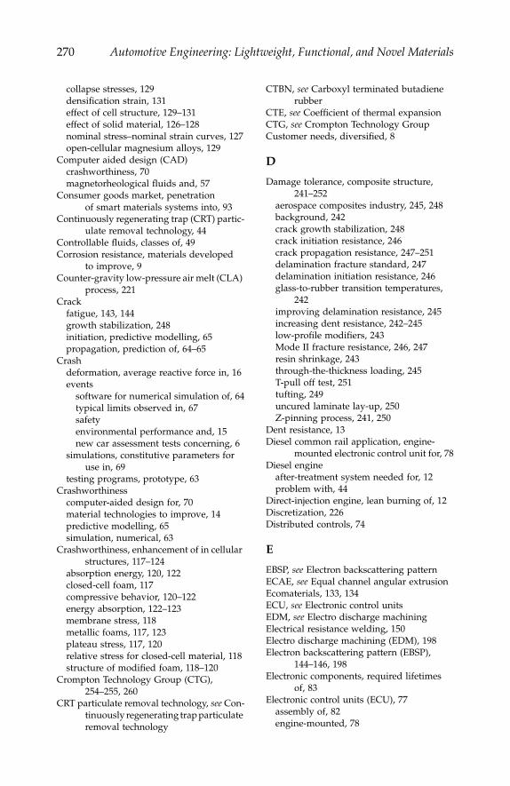
270
Automotive Engineering: Lightweight, Functional, and Novel Materials
collapse stresses, 129densification strain, 131effect of cell structure, 129–131effect of solid material, 126–128nominal stress–nominal strain curves, 127open-cellular magnesium alloys, 129
Computer aided design (CAD)crashworthiness, 70magnetorheological fluids and, 57
Consumer goods market, penetration of smart materials systems into, 93
Continuously regenerating trap (CRT) partic-ulate removal technology, 44
Controllable fluids, classes of, 49Corrosion resistance, materials developed
to improve, 9Counter-gravity low-pressure air melt (CLA)
process, 221Crack
fatigue, 143, 144growth stabilization, 248initiation, predictive modelling, 65propagation, prediction of, 64–65
Crashdeformation, average reactive force in, 16events
software for numerical simulation of, 64typical limits observed in, 67safetyenvironmental performance and, 15new car assessment tests concerning, 6
simulations, constitutive parameters for use in, 69
testing programs, prototype, 63Crashworthiness
computer-aided design for, 70material technologies to improve, 14predictive modelling, 65simulation, numerical, 63
Crashworthiness, enhancement of in cellular structures, 117–124
absorption energy, 120, 122closed-cell foam, 117compressive behavior, 120–122energy absorption, 122–123membrane stress, 118metallic foams, 117, 123plateau stress, 117, 120relative stress for closed-cell material, 118structure of modified foam, 118–120
Crompton Technology Group (CTG), 254–255, 260
CRT particulate removal technology,
see
Con-tinuously regenerating trap particulate removal technology
CTBN,
see
Carboxyl terminated butadiene rubber
CTE,
see
Coefficient of thermal expansionCTG,
see
Crompton Technology GroupCustomer needs, diversified, 8
D
Damage tolerance, composite structure, 241–252
aerospace composites industry, 245, 248background, 242crack growth stabilization, 248crack initiation resistance, 246crack propagation resistance, 247–251delamination fracture standard, 247delamination initiation resistance, 246glass-to-rubber transition temperatures,
242improving delamination resistance, 245increasing dent resistance, 242–245low-profile modifiers, 243Mode II fracture resistance, 246, 247resin shrinkage, 243through-the-thickness loading, 245T-pull off test, 251tufting, 249uncured
laminate lay-up, 250Z-pinning process, 241, 250
Dent resistance, 13Diesel common rail application, engine-
mounted electronic control unit for, 78Diesel engine
after-treatment system needed for, 12problem with, 44
Direct-injection engine, lean burning of, 12Discretization, 226Distributed controls, 74
E
EBSP,
see
Electron backscattering patternECAE,
see
Equal channel angular extrusionEcomaterials, 133, 134ECU,
see
Electronic control unitsEDM,
see
Electro discharge machiningElectrical resistance welding, 150Electro discharge machining (EDM), 198Electron backscattering pattern (EBSP),
144–146, 198Electronic components, required lifetimes
of, 83Electronic control units (ECU), 77
assembly of, 82engine-mounted, 78
IP155_C020.fm Page 270 Monday, December 31, 2007 5:08 PM
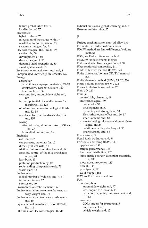
Index
271
failure probabilities for, 83localization of, 77
Electronicshybrid vehicle, 73integration of mechanics with, 77market, automotive, size of, 75systems, strategies for, 74
Electrorheological (ER) fluids, 49carrier oils, 50development of, 50device, design of, 56dynamic yield strengths of, 50smart systems and, 88
Emissions levels, vehicle speed and, 8Encapsulated knowledge statements, 226Energy
absorptioncapabilities, employed materials, 69–70compressive tests to evaluate, 120fiber fracture, 166
consumption, automobile weight and, 109
impact, potential of metallic foams for absorbing, 117, 123
of interaction, magnetorheological fluids and, 52, 53
interfacial fracture, sandwich structure and, 153
savingeffect of using aluminum Audi ASF car
on, 27from all-aluminum car, 26
Engine(s)cold start, 42components, materials for, 10diesel, problem with, 44friction, fuel consumption loss and, 14gasoline, control of the intake/exhaust
valves, 78lean-burn, 43pollution production by, 42self-standing component-ready, 78warm start, 42
Environmentglobal number of vehicles and, 4, 5important issues, 12stresses on, 40
Environmental embrittlement, 197Environmental improvement features, car
body weight and, 19Environmental performance, crash safety
and, 15Equal channel angular extrusion (ECAE),
112, 114ER fluids,
see
Electrorheological fluids
Exhaust emissions, global warming and, 5Extreme cold-forming, 25
F
Fatigue crack initiation sites, Al alloy, 134FC model,
see
Full constraints modelFD/FV method,
see
Finite difference/volume method
FDM,
see
Finite difference methodFEM,
see
Finite elements methodFiat, smart adaptive design concept, 92Fiber-reinforced composites, 241Finite difference method (FDM), 224Finite difference/volume (FD/FV) method,
225Finite elements method (FEM), 25, 26, 224Finite volume method (FVM), 224Firewall, electronic control on, 77Flow-3D, 227Fluid(s)
controllable, classes of, 49electrorheological, 49
carrier oils, 50development of, 50dynamic yield strengths of, 50Electrorheological effect and, 56–57smart systems and, 88
magnetorheological,
see also
Magnetorheo-logical fluids
real-time adaptive rheology of, 90smart systems and, 88
Flux closure, 52Fossil fuels, pollution and, 39Friction stir welding (FSW), 180
applications, 183fatigue performance, 184hardness distribution, 182joints made between dissimilar materials,
184, 185mechanical properties, 183orbital, 180principle of, 181weld nugget, 181
FSW,
see
Friction stir weldingFuel
consumptionautomobile weight and, 97loss, engine friction and, 14reduction in, safety improvement and,
63economy
COP3 targets for improving, 5improvement of, 3vehicle weight and, 12
IP155_C020.fm Page 271 Monday, December 31, 2007 5:08 PM

272
Automotive Engineering: Lightweight, Functional, and Novel Materials
Full constraints (FC) model, 101, 102, 107FVM,
see
Finite volume method
G
Gasoline engines, control of the intake/exhaust valves, 78
Global warming, cause of, 5GM Saturn engine plant, long series casting
runs at, 218GMT compounds, 242Goretex™, 188
H
Hall–Petch (H–P) relations, 111Harmonization, 4HAZ,
see
Heat-affected zoneHealth and usage monitoring systems
(HUMS), 87Heat-affected zone (HAZ), 194High-pressure die-casting (HPDC), 221High-temperature electronic materials,
73–85accelerated testing, 84assembly process, 82–83HITEN network, 84major market driver for development of, 76market perspective, 75–77module technology, 77–79packaging and interconnection technology,
81–82packaging materials, 81reliability, 83–84silicon development, 79–81silicon-on-insulator, 80
High temperature electronics (HTE), 75HIPed alloys,
see
Hot isostatically pressed alloys
HITEN network, 84Hot-forming, 25Hot isostatically pressed (HIPed) alloys,
198HPDC,
see
High-pressure die-castingH–P relations,
see
Hall–Petch relationsHSSA,
see
Hybrid stainless steel assemblyHTE,
see
High temperature electronicsHuman–machine interface, 7HUMS,
see
Health and usage monitoring systems
Hybrid materials, 88Hybrid stainless steel assembly (HSSA), 150Hybrid vehicle electronics, 73Hydrocarbon emissions, restriction of, 40Hydro-forming, 25
I
Impact energy, potential of metallic foams for absorbing, 117, 123
Impact loading, 63–71adopted methodology, 65–66employed materials, total energy absorp-
tion capabilities, 69–70failure modelling capabilities, 65inverse modelling techniques, 65, 66jointing systems failure, prediction of, 65loading rig types, 67nonmeasurable modelling parameters, 66research focus, 67–70
experimental focus, 67numerical focus, 67–70
strain rates, 67Information
global networks for, 9safety, 6
Infrared absorbing pigments, laser welding and, 187
Intake/exhaust valves, control of, 78Intelligent transportation systems (ITS), 4,
7–8Interconnect technologies
contact of, 83electronic systems of, 82
Interesting materials looking for an applica-tion, 93
Intermetallic alloys,
see
Titanium aluminide-based intermetallic
ITS,
see
Intelligent transportation systems
J
Japan, use of modular parts by, 30Japanese market, materials used in vehicle
for, 11Joining,
see
Welding and joiningJointing systems failure, prediction of, 65Joints, properties of, 179
K
Keiretsu companies, 9Keronite coating process, 255–256Kyoto Protocol, targets for reducing CO
2
emissions set by, 5
L
Lankford value, 97Laser welding, 187, 194LCP,
see
Liquid crystal polymer
IP155_C020.fm Page 272 Monday, December 31, 2007 5:08 PM

Index
273
LDR,
see
Limiting drawing ratioLean-burn engines, 43LFT,
see
Long fiber thermoplasticLight-off temperature, 40, 42Limiting drawing ratio (LDR), 97, 103Liquid crystal polymer (LCP), 33
composites, recyclability of, 34price of, 34
Long fiber thermoplastic (LFT), 31Low profile additive (LPA), 243LPA,
see
Low profile additiveLTCC substrates, main use for, 81
M
MAC method,
see
Marker and cell methodMagnesium, ductile, 109–116
effect of refining grain size, 110–111effect of texture, 112–115elongation-to-failure of, 109, 110, 111,
114–115equal channel angular extrusion, 112, 114
Magnesium alloy(s)deformed microstructure of, 112directly extruded, X-ray diffraction spectra
of, 113Hall–Petch relations of, 111nominal stress–nominal strain curves
of, 127open-cellular, 129, 130specific strength–ductility balance, 114stress-strain relation of, 131strong, 258susceptibility of to corrosion, 254texture controlled, 115uses of, 109
Magnesium ductility, enhancement of, 109, 115
Magnetorheological fluids, 49–62applications, 50carrier oils, 50colloidal particle interaction, 56damper, 57–61
damper test results, 58–60effects of temperature, 60–61load-bearing capacity, 60prototype, 58, 61, 62response time, 58, 59, 60variation of load with piston velocity,
58, 59dispersed magnetic particles, 52domain structure, 53effect of applied DC magnetic field
on viscosity, 55electrorheological effect, 51
electrorheological and magnetorheological devices, 56–57
energy of interaction, 52, 53flux closure, 52historical developments, 50–51
electrorheological fluids, 50–51magnetorheological fluids, 51
inverse cube law, 52magnetic behavior, 53–54magnetic dipole, 52magnetic field generation in, 57magnetization curve, 54material saturation magnetization, 53noise pollution and, 50original application, 51other devices, 61–62real-time adaptive rheology of, 90residual magnetization, 53rheological behavior, 54–56slip clutches and, 61–62smart systems and, 88structure of, 51–53thixotropic agents, 51variation of shear stress with shear rate, 56viscosity versus shear rate, 54, 55
Marker and cell (MAC) method, 227Mass production technologies, vehicle
demand and, 9Material(s),
see also
High-temperature elec-tronic materials; Smart materials; Vehi-cles and materials technologies, future
friction heating of, 180high-strength, lightweight, example com-
ponents from, 64hybrid, 88joining technology, 179,
see also
Welding and joining
lightweight, rethinking of design proce-dures using, 70
new, cost competitiveness and, 17output from single, 88polycrystalline
orientation distribution function in, 99texture control, 98
suppliers, cooperation of carmakers and, 3Mechatronic modules, 74Mechatronics, shock tolerance, 75Mechatronic systems, hybrid, accelerometers
and actuators of, 89Mechatronic Train Control Unit, 79Mercedes Benz’s automatic gearboxes, shape
memory alloy valves in, 91
Mesh diffusion, 226Mesocomplex structure, 134, 136
Metal matrix composite, 144
IP155_C020.fm Page 273 Monday, December 31, 2007 5:08 PM

274
Automotive Engineering: Lightweight, Functional, and Novel Materials
Metal vapour deposition (MVD), 47Methods engineer, 224Microcellular plastic
key characteristics of, 34manufacture of, 34process, technical issues, 35
Mission profile, 81Model(s)
cantilever bending, sandwich structure, 155, 157
catalysts, 46–47full constraints, 100, 102, 107relaxed constraints, 101, 102Taylor, 100, 107
Modularization,
see
Plastic technology, auto-motive module
Module carriersinjection-molded, 31, 32main materials for, 30
MVD,
see
Metal vapour deposition
N
Nanocomposites, 33NCAP,
see
New car assessment programNd:YAG lasers, 187, 188New car assessment program (NCAP)
results of car crash tests under, 6trends in, 7
Noise control, vibration control and, 92Noise pollution, 50NO
x
conversion process, 44NO
x
storage and reduction (NSR) catalysts, 44NSR catalysts,
see
NO
x
storage and reduction catalysts
O
ODF,
see
Orientation distribution functionOil crises, fuel consumption issue during,
9–10Oil production, global, 5OM,
see
Optical microscopyOptical fiber, sensual structures containing,
88, 89Optical microscopy (OM), 198Orientation distribution function (ODF), 98Outer panels, trends in aluminum sheet
usage for, 13, 14
P
PA,
see
PolyamidePaint bake-hardening, mechanism of, 22PAN,
see
Peroxy acetyl nitrate
Particulate removal technology, continuously regenerating trap, 44
Part weight reductions, achievement of, 16Passenger comfort subsystems, smart
materials and, 94PED,
see
Plasma electrolytic depositionPedestrian safety legislation, European, 92PEO,
see
Plasma electrolytic oxidationPeroxy acetyl nitrate (PAN), 40PES,
see
Plasma electrolytic saturationPhase field theory, 224–225Plasma electrolytic deposition (PED), 254Plasma electrolytic oxidation (PEO), 254Plasma electrolytic saturation (PES), 254Plastic technology, automotive module,
29–35development trends, 30–32
applications and benefits, 32injection-molded polypropylene rein-
forced by long glass fibers, 31–32long fiber thermoplastic, 31new materials, 32new processes, 32plastic/steel hybrid, 31stamping mold, 31
future technology, 33–35materials, 33–34processing techniques, 34–35
modularization methods, 30module carrier requirements, 30
PMMA,
see
Poly(methyl methacrylate)Pollution,
see
also
Catalysts, automotiveengine start and, 42events, fossil fuels and, 39load, 40types, 40
Polyamide (PA), 31Polycrystalline materials
Orientation distribution function in, 99texture control, 98
Polyester/chopped glass fiber composites, toughening of, 241
Polymer-based composites, autosport, 260Poly(methyl methacrylate) (PMMA),
187, 246Polypropylene (PP), 30
/liquid crystal polymer, load-displacement curves for, 33, 34
nanocomposites, 33Polyvinyl acetate (PVAc), 243Powertrain
components, materials for, 11drive-by-wire control systems, 73management, evolution of, 74modules, smart, 74
IP155_C020.fm Page 274 Monday, December 31, 2007 5:08 PM
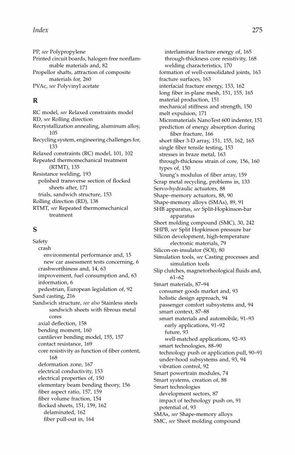
Index
275
PP,
see
PolypropylenePrinted circuit boards, halogen-free nonflam-
mable materials and, 82Propellor shafts, attraction of composite
materials for, 260PVAc,
see
Polyvinyl acetate
R
RC model,
see
Relaxed constraints modelRD,
see
Rolling directionRecrystallization annealing, aluminum alloy,
105Recycling system, engineering challenges for,
133Relaxed constraints (RC) model, 101, 102Repeated thermomechanical treatment
(RTMT), 135Resistance welding, 193
polished transverse section of flocked sheets after, 171
trials, sandwich structure, 153Rolling direction (RD), 138RTMT,
see
Repeated thermomechanical treatment
S
Safetycrash
environmental performance and, 15new car assessment tests concerning, 6
crashworthiness and, 14, 63improvement, fuel consumption and, 63information, 6pedestrian, European legislation of, 92
Sand casting, 216Sandwich structure,
see
also
Stainless steels sandwich sheets with fibrous metal cores
axial deflection, 158bending moment, 160cantilever bending model, 155, 157contact resistance, 169core resistivity as function of fiber content,
168deformation zone, 167electrical conductivity, 153electrical properties of, 150elementary beam bending theory, 156fiber aspect ratio, 157, 159fiber volume fraction, 154flocked sheets, 151, 159, 162
delaminated, 162fiber pull-out in, 164
interlaminar fracture energy of, 165through-thickness core resistivity, 168welding characteristics, 170
formation of well-consolidated joints, 163fracture surfaces, 163interfacial fracture energy, 153, 162long fiber in-plane mesh, 151, 155, 165material production, 151mechanical stiffness and strength, 150melt expulsion, 171Micromaterials NanoTest 600 indenter, 151prediction of energy absorption during
fiber fracture, 166short fiber 3-D array, 151, 155, 162, 165single fiber tensile testing, 153stresses in braze metal, 163through-thickness strain of core, 156, 160types of, 150Young’s modulus of fiber array, 159
Scrap metal recycling, problems in, 133Servo-hydraulic actuators, 88Shape–memory actuators, 88, 90Shape-memory alloys (SMAs), 89, 91SHB apparatus,
see
Split-Hopkinson-bar apparatus
Sheet molding compound (SMC), 30, 242SHPB,
see
Split Hopkinson pressure barSilicon development, high-temperature
electronic materials, 79Silicon-on-insulator (SOI), 80Simulation tools,
see
Casting processes and simulation tools
Slip clutches, magnetorheological fluids and, 61–62
Smart materials, 87–94consumer goods market and, 93holistic design approach, 94passenger comfort subsystems and, 94smart context, 87–88smart materials and automobile, 91–93
early applications, 91–92future, 93well-matched applications, 92–93
smart technologies, 88–90technology push or application pull, 90–91under-hood subsystems and, 93, 94vibration control, 92
Smart powertrain modules, 74Smart systems, creation of, 88Smart technologies
development sectors, 87impact of technology push on, 91potential of, 93
SMAs,
see
Shape-memory alloysSMC,
see
Sheet molding compound
IP155_C020.fm Page 275 Monday, December 31, 2007 5:08 PM

276
Automotive Engineering: Lightweight, Functional, and Novel Materials
Smog, Los Angeles, 40Smoothed particle hydrodynamics (SPH),
232SOI,
see
Silicon-on-insulatorSolder
bumping, 81materials, lead-free, 82
SPH,
see
Smoothed particle hydrodynamicsSplit-Hopkinson-bar (SHB) apparatus, 67Split-Hopkinson-pressure bar (SHPB), 120Stainless steels sandwich sheets with fibrous
metal cores, 149–175,
see also
Sandwich structure
characteristics of, 172experimental procedures, 151–155
electrical conductivity, 153geometrical representation of core struc-
ture, 154–155interfacial fracture energy, 153material production, 151resistance welding, 153–154single fiber tensile testing, 153through-thickness stiffness, 151–152through-thickness yield stress, 152–153
fracture energy during delamination of faceplates, 173
through-thickness electrical resistance of core, 168–172
brazed in-plane mesh and 3-D array,169–170
flocked sheet, 168–169welding characteristics, 170–172
through-thickness electrical resistivities, 173through-thickness loading response, 155–168
core stiffness, 155–160core strength and yielding behavior,
160–162fiber fracture in in-plane mesh and 3-D
array, 165–168fiber pull-out in flocked sheets, 164–165interfacial fracture energy, 162–163
variants, 172Stamping mold, 31Starter–generator system, multifunctional, 79Steel(s)
alloy, rate dependency, 68low carbon, deep drawability in, 97relaxed constraints model in, 101transformation induced plasticity, 193vibration-damped, welding of, 150
T
Taylor model, aluminum alloy, 100, 107TCU,
see
Train Control Unit
Telecommunications, high density intercon-nection technology from, 82
Telematic systems, evolution of, 73Titanium aluminide-based intermetallic
alloys, 197–207alloy compositions, 199benefit of intermetallic alloys, 197brittle-ductile transition temperature, 201,
202embrittlement mechanism, 204–206environmental embrittlement, 197fabrication procedures, 199fracture stress, 201, 202hydrogen behavior, 204, 206microstructures, 199, 200, 203moisture-induced embrittlement, 200–203,
204, 205propagating micro-crack, 204tensile tests, 202TiAl-based alloys, 198–199
Train Control Unit (TCU), 79Transformation induced plasticity (TRIP)
steels, 193Transmission-welding technique, 186TRIP steels,
see
Transformation induced plas-ticity steels
Turbo-prop aircraft sector, smart-structural technology from, 92
U
Under-hood subsystems, smart materials and, 93, 94
Under-hood temperatures, 78
V
Vehiclecrash safety, 6demand, mass production technologies
and, 9information safety, 6number of, global population and, 4, 6speed, emission levels and, 8weight, fuel economy and, 12weight reductionk-value of materials for, 16use of aluminum alloy sheets in achieving,
10, 13, 27Vehicles and materials technologies, future,
3–17automotive materials, 9–12
body materials, 9–10chassis and powertrain components, 11
IP155_C020.fm Page 276 Monday, December 31, 2007 5:08 PM
Index
277
engine components, 10future direction of, 11–12
environmental issues, 4–6environmental viewpoint, 12–14intelligent transportation systems, 4, 7–8market trends, 8–9safety, 6safety viewpoint, 14–16
Vibration control, noise control and, 92VOF method,
see
Volume of fluid methodVolume of fluid (VOF) method, 227
W
Warm start, 42Water quenching (WQ), 137Wavelength dispersive spectroscopy (WDS),
198WDS,
see
Wavelength dispersive spectroscopyWEEE directive, 82Welding
friction stir, 180laser, 194resistance
electrical, 150polished transverse section of flocked
sheets after, 171spot, 193
Welding and joining, 179–195adhesives, 189
advantages, 189components, 190concerns about, 189curing, 190, 192fasteners, 191–192hybrid joint, 191
process, 190strength of bond, 190
AdhFAST™, 189–193Clearweld™, 186–189friction stir welding, 180–185
applications, 183fatigue performance, 184hardness distribution, 182joints made between dissimilar materi-
als, 184, 185mechanical properties, 183orbital, 180principle of, 181weld nugget, 181
laser welding of high-strength steels, 193–194
fast weld-cooling rates, 193heat-affected zone, 194resistance spot welding, 193
mechanical testing on woven fabrics, 188transformation induced plasticity steels,
193Woven fabric(s)
composites, damage resistance of, 249mechanical testing on, 188
WQ,
see
Water quenching
X
X-ray diffraction (XRD), 198XRD,
see
X-ray diffraction
Z
Zinc, elongation-to-failure of, 109Z-pins, 250
IP155_C020.fm Page 277 Monday, December 31, 2007 5:08 PM

IP155_C020.fm Page 278 Monday, December 31, 2007 5:08 PM

Related Documents