578 IEEE TRANSACTIONS ON POWER ELECTRONICS, VOL. 21, NO. 3, MAY 2006 Automotive DC–DC Bidirectional Converter Made With Many Interleaved Buck Stages Oscar García, Member, IEEE, Pablo Zumel, Angel de Castro, and José A. Cobos, Member, IEEE Abstract—Interleaving technique is used in some applications due to its advantages regarding filter reduction, dynamic response, and power management. In dual battery system vehicles, the bidi- rectional dc–dc converter takes advantage of this technique using three-to-five paralleled buck stages. In this paper, we propose the use of a much higher number of phases in parallel together with digital control. It will be shown that this approach opens new possibilities since changes in the tech- nology are possible. Thus, two 1000-W prototypes have been de- signed using surface mount technology devices (SO-8 transistors). An additional important feature is that due to the accuracy of the digital device [field-programmable gate array (FPGA)], current loops have been eliminated, greatly simplifying the implementa- tion of the control stage. Index Terms—Digital control, field-programmable gate array (FPGA), surface mount technology (SMT). I. INTRODUCTION A UTOMOTIVE electronics are one field of power elec- tronics that has been growing rapidly in recent years. Some good examples of this are the electronics involved in the dual battery system vehicles that use 14-V and 42-V batteries. One of the specific converters for these vehicles is the bidi- rectional module placed in between those batteries that is in charge of the power flow. Typically, the power of this converter ranges from 500 to 1000 W. Due to the relative high current of this application, some approaches use the interleaving tech- nique [1]. The main advantages of using this technique in this application are the filter’s reduction and efficiency. State of the art engineering for this application proposes the use of three to five paralleled buck stages (phases) to build the converter [2]–[5]. A comparison between this multiphase converter with a single buck converter is carried out in [2], where the advantage of this technique for this application can be seen. Reference [3] proposes a CAD tool to calculate the number of phases to optimize cost, size, and weight. A similar analysis, but more oriented to calculate power losses, can be found in [4]. A magnetic component to couple all the phases is introduced in [5], obtaining a size reduction compared with inductors for the same power losses. A quite different solution is presented in [6], where the authors propose a multilevel converter to Manuscript received March 9, 2005; revised October 26, 2005. This work was presented in part at PESC’04 and APEC’05. Recommended by Associate Editor J. Shen. O. García, A. de Castro, and J. A. Cobos are with the División de Inge- niería Electrónica, Universidad Politécnica de Madrid, Madrid 28006, Madrid. (e-mail: [email protected]). P. Zumel is with the Departamento de Tecnología Electrónica, Universidad Carlos III de Madrid, Madrid, Spain. Digital Object Identifier 10.1109/TPEL.2006.872379 decrease the voltage stress in the transistors and to eliminate the inductor. Finally, a procedure to design this type of power converter based on models implemented in Matlab is shown in [7]. References [2] and [3] are deeply analyzed and compared in Table II. Using interleaving, the power stage of a converter is divided into several and smaller power stages. Therefore, the size of each component is reduced. With a very high number of inter- leaved phases, the current stress is greatly reduced and using a different technology becomes a possibility. This change of tech- nology may bring several advantages: • power converter is made of surface mount technology (SMT) components; • automatic assembly; • absence of heatsinks (usually heatsinks require manual as- sembly); • magnetic components can be planar or SMT. Repetitivity is greatly increased; • very small input and output filters. However, there are some challenges to face a many-phases converter. • General purpose integrated circuits (ICs) cannot be used because there are many phases. Specific digital control is required. • Introducing a current loop per phase will not be cost-effec- tive. Passive current equalization should be considered. In this paper, two multiphase dc/dc converters made of many interleaved phases (16 and 36) for automotive application are proposed. Apart from the aforementioned advantages, the mea- sures in the prototypes show a very good efficiency (94%–95%) at full load (1000 W). II. POWER STAGE DESIGN The converter will be implemented using the synchronous buck configuration because it is suitable for this specification and it is used for most of the authors [2]–[5]. It has bidirec- tional capability and efficiency is quite good. No isolation is needed between both batteries and therefore, topologies with transformers are unnecessary. Fig. 1 shows a multiphase syn- chronous buck dc/dc converter. The design has been guided by the compromise of using SMT components. The number of phases has been selected to reduce the dc current enough to use small transistors. Thus, two de- signs have been considered as shown in Table I. In the first one, with 16 phases, each metal-oxide-semiconductor field-ef- fect transistor (MOSFET) needs a SO-8 case while the second, with 36 phases, has its two MOSFETs of each phase in the same SO-8 case. 0885-8993/$20.00 © 2006 IEEE

Welcome message from author
This document is posted to help you gain knowledge. Please leave a comment to let me know what you think about it! Share it to your friends and learn new things together.
Transcript

578 IEEE TRANSACTIONS ON POWER ELECTRONICS, VOL. 21, NO. 3, MAY 2006
Automotive DC–DC Bidirectional ConverterMade With Many Interleaved Buck Stages
Oscar García, Member, IEEE, Pablo Zumel, Angel de Castro, and José A. Cobos, Member, IEEE
Abstract—Interleaving technique is used in some applicationsdue to its advantages regarding filter reduction, dynamic response,and power management. In dual battery system vehicles, the bidi-rectional dc–dc converter takes advantage of this technique usingthree-to-five paralleled buck stages.
In this paper, we propose the use of a much higher number ofphases in parallel together with digital control. It will be shownthat this approach opens new possibilities since changes in the tech-nology are possible. Thus, two 1000-W prototypes have been de-signed using surface mount technology devices (SO-8 transistors).An additional important feature is that due to the accuracy of thedigital device [field-programmable gate array (FPGA)], currentloops have been eliminated, greatly simplifying the implementa-tion of the control stage.
Index Terms—Digital control, field-programmable gate array(FPGA), surface mount technology (SMT).
I. INTRODUCTION
AUTOMOTIVE electronics are one field of power elec-tronics that has been growing rapidly in recent years.
Some good examples of this are the electronics involved in thedual battery system vehicles that use 14-V and 42-V batteries.One of the specific converters for these vehicles is the bidi-rectional module placed in between those batteries that is incharge of the power flow. Typically, the power of this converterranges from 500 to 1000 W. Due to the relative high currentof this application, some approaches use the interleaving tech-nique [1]. The main advantages of using this technique in thisapplication are the filter’s reduction and efficiency. State of theart engineering for this application proposes the use of threeto five paralleled buck stages (phases) to build the converter[2]–[5]. A comparison between this multiphase converter with asingle buck converter is carried out in [2], where the advantageof this technique for this application can be seen. Reference[3] proposes a CAD tool to calculate the number of phases tooptimize cost, size, and weight. A similar analysis, but moreoriented to calculate power losses, can be found in [4]. Amagnetic component to couple all the phases is introduced in[5], obtaining a size reduction compared with inductors forthe same power losses. A quite different solution is presentedin [6], where the authors propose a multilevel converter to
Manuscript received March 9, 2005; revised October 26, 2005. This workwas presented in part at PESC’04 and APEC’05. Recommended by AssociateEditor J. Shen.
O. García, A. de Castro, and J. A. Cobos are with the División de Inge-niería Electrónica, Universidad Politécnica de Madrid, Madrid 28006, Madrid.(e-mail: [email protected]).
P. Zumel is with the Departamento de Tecnología Electrónica, UniversidadCarlos III de Madrid, Madrid, Spain.
Digital Object Identifier 10.1109/TPEL.2006.872379
decrease the voltage stress in the transistors and to eliminatethe inductor. Finally, a procedure to design this type of powerconverter based on models implemented in Matlab is shown in[7]. References [2] and [3] are deeply analyzed and comparedin Table II.
Using interleaving, the power stage of a converter is dividedinto several and smaller power stages. Therefore, the size ofeach component is reduced. With a very high number of inter-leaved phases, the current stress is greatly reduced and using adifferent technology becomes a possibility. This change of tech-nology may bring several advantages:
• power converter is made of surface mount technology(SMT) components;
• automatic assembly;• absence of heatsinks (usually heatsinks require manual as-
sembly);• magnetic components can be planar or SMT. Repetitivity
is greatly increased;• very small input and output filters.However, there are some challenges to face a many-phases
converter.• General purpose integrated circuits (ICs) cannot be used
because there are many phases. Specific digital control isrequired.
• Introducing a current loop per phase will not be cost-effec-tive. Passive current equalization should be considered.
In this paper, two multiphase dc/dc converters made of manyinterleaved phases (16 and 36) for automotive application areproposed. Apart from the aforementioned advantages, the mea-sures in the prototypes show a very good efficiency (94%–95%)at full load (1000 W).
II. POWER STAGE DESIGN
The converter will be implemented using the synchronousbuck configuration because it is suitable for this specificationand it is used for most of the authors [2]–[5]. It has bidirec-tional capability and efficiency is quite good. No isolation isneeded between both batteries and therefore, topologies withtransformers are unnecessary. Fig. 1 shows a multiphase syn-chronous buck dc/dc converter.
The design has been guided by the compromise of using SMTcomponents. The number of phases has been selected to reducethe dc current enough to use small transistors. Thus, two de-signs have been considered as shown in Table I. In the firstone, with 16 phases, each metal-oxide-semiconductor field-ef-fect transistor (MOSFET) needs a SO-8 case while the second,with 36 phases, has its two MOSFETs of each phase in the sameSO-8 case.
0885-8993/$20.00 © 2006 IEEE
GARCÍA et al.: AUTOMOTIVE DC–DC BIDIRECTIONAL CONVERTER 579
Fig. 1. Multiphase synchronous buck dc/dc converter.
TABLE IBRIEF OVERVIEW OF THE TWO PROPOSED DESIGNS
The key design parameter is the number of phases and thephase current ripple. It is not easy to determine it since manycalculations should be done and many technologies should betaken into account. A guideline can be found in [8]. Note thatthe effect of increasing the number of phases in each particularcomponent (transistors, inductors, capacitors) is different. Hereis a brief summary.
• Transistors: there are three types of power losses in theMOSFETs. Both conduction and capacitive losses are rel-atively easy to calculate being proportional to the on-resis-tance and capacitances, respectively. However, switchinglosses are much more complex because they depend ona higher number of parameters, some of them out of theswitch itself (leakage inductance, driver output current,
). In a first approximation, these losses are calculatedusing the constant switching time of the device given inthe datasheet. However, in the real world, these switchingtimes (rise and fall times) are load dependent.For a given MOSFET technology (product is con-stant) there is no advantage in increasing the number ofphases if the total area of silicon is the same: a highernumber of phases will use smaller transistors. Therefore,each transistor has a higher on-resistance but handles lesscurrent keeping the conduction losses constant. The same
Fig. 2. PCB windings of the RM7 inductor and phase layout.
can be said about the capacitive losses because each tran-sistor has a smaller capacitance but the addition of all ofthem is constant. Switching losses are also constant if riseand fall times are considered independent of the number ofphases.In the case of using discrete semiconductors, the calcula-tions should be done for each particular design since thetechnology is different for each manufacturer. At least, theadvantage of using a high number of phases is that due toripple cancellation the switching frequency can be reducedand, therefore, the switching and capacitive losses are re-duced.
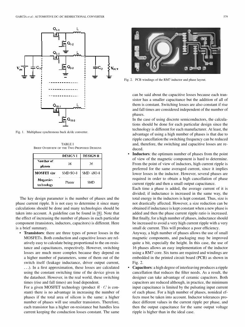
• Inductors: the optimum number of phases from the pointof view of the magnetic component is hard to determine.From the point of view of inductors, high current ripple ispreferred for the same averaged current, since it implieslower losses in the inductor. However, several phases arerequired in order to obtain a high cancellation of phasecurrent ripple and then a small output capacitance.Each time a phase is added, the average current of it isdivided; if inductance is increased in the same way, thetotal energy in the inductors is kept constant. Thus, size isnot drastically affected. However, a size reduction can beobtained if inductance is kept constant when a new phase isadded and then the phase current ripple ratio is increased.But finally, for a high number of phases, inductance shouldbe increased to avoid a very high current ripple with a verysmall dc current. This will produce a poor efficiency.Anyway, a high number of phases allows the use of smallmagnetic components, and packaging may be improvedquite a bit, especially the height. In this case, the use of16 phases allows an easy implementation of the inductorusing a RM7 core. Six turns are required and windings areembedded in the printed circuit board (PCB) as shown inFig. 2.
• Capacitors: a high degree of interleaving produces a ripplecancellation that reduces the filter needs. As a result, thedesigner can take advantage of ceramic capacitors. Bothcapacitors are reduced although, in practice, the minimuminput capacitance is limited by the pulsating input currentof each phase. For a high number of phases, nonideal ef-fects must be taken into account. Inductor tolerances pro-duce different values in the current ripple per phase, andthen the output capacitance for the same output voltageripple is higher than in the ideal case.
580 IEEE TRANSACTIONS ON POWER ELECTRONICS, VOL. 21, NO. 3, MAY 2006
TABLE IICOMPARISON OF SEVERAL DC/DC CONVERTERS FOR THE SAME APPLICATION BUT WITH DIFFERENT NUMBER OF INTERLEAVED PHASES
Another advantage of interleaving is ripple cancellation [9].With a very high number of phases, the current ripple at theoutput is nearly negligible at every input voltage. Therefore, theoutput capacitor is really small.
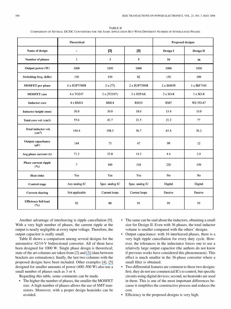
Table II shows a comparison among several designs for theautomotive 42/14-V bidirectional converter. All of them havebeen designed for 1000 W. Single phase design is theoretical;state of the art columns are taken from [2] and [3] (data betweenbrackets are estimations); finally, the last two columns with theproposed designs have been included. Other examples [4], [5]designed for smaller amounts of power (400–500 W) also use asmall number of phases such as 3 or 4.
Regarding this table, some comments can be made.• The higher the number of phases, the smaller the MOSFET
size. A high number of phases allows the use of SMT tran-sistors. Moreover, with a proper design heatsinks can beavoided.
• The same can be said about the inductors, obtaining a smallsize for Design II. Even with 36 phases, the total inductorvolume is smaller compared with the others’ designs.
• Output capacitance: with 16 interleaved phases, there is avery high ripple cancellation for every duty cycle. How-ever, the tolerances in the inductance forces one to use arelatively large output capacitor (the authors do not knowif previous works have considered this phenomenon). Thiseffect is much smaller in the 36-phase converter where asmall filter is obtained.
• Two differential features are common to these two designs:first, they do not use commercial ICs to control, but specificcircuits using digital devices; second, no heatsinks are usedin them. This is one of the most important differences be-cause it simplifies the constructive process and reduces thecost.
• Efficiency in the proposed designs is very high.
GARCÍA et al.: AUTOMOTIVE DC–DC BIDIRECTIONAL CONVERTER 581
Fig. 3. Simplified control scheme implemented in a FPGA to control the con-verter.
The main conclusion obtained from the previous table is thatin using many phases, a change of technology is possible ob-taining very good results from the point of view of efficiencyand size.
From the point of view of cost, the present approach hasone differential advantage compared with other solutions of thestate of the art: all the components are SMD including induc-tors and, therefore, the converter can be mounted automatically.This drastically reduces the cost when compared with manualassembly. Moreover, the absence of heatsinks significantly sim-plifies the mechanical issues. On the other hand, these designsrequire more components.
III. CONTROL STAGE DESIGN
The control circuit is in charge of generating the driving sig-nals for the 16 phases, that is, 32 transistors in Design I and36 (72 transistors) in Design II. Since the converter is bidirec-tional, input and output voltages should be measured to generatepulses. Interleaved converters proposed in the state of the art dorequire a current loop in each phase to control the dc current perphase.
Using a digital control, the accuracy of these pulses is so highthat the present phase’s current are not measured. Therefore, thecontrol circuit is quite simple. Although there are other factorsthat affect current unbalance, this is the main factor responsable.
The control stage is digital and has been implemented in afield-programmable gate array (FPGA). A general scheme isshown in Fig. 3. The digital circuit is composed of five parts.
• ADC interface and filter: control of analog to digital con-verters and filter to remove noise from samples.
• Regulator: it calculates duty cycle. Its control algorithmhas been designed using the root-locus technique and cal-culated directly in the digital domain for obtaining betterresults.
• MCD generator: generates the pulse for the free-wheelingtransistor. Thus, the converter changes automatically toDCM when possible (usually at low load).
• Phase shifter: this block generates shifted signals form theduty cycle [10].
• Protections: some basic protections are included. The ad-vantage is that they are included without additional cost.
The control circuit has been implemented in a XilinxXCV200E FPGA. The final control circuit is quite small using
Fig. 4. Addition and comparison of (a) hardware structure and (b) its workings.
10 085 equivalent gates (3.4% of the device), so a smallerand cheaper FPGA could also be used. Thanks to the FPGAconcurrency (all its logic is executed in parallel) a high numberof driving signals can be generated without any drawback inthe performance of the rest of the controller. Furthermore, itshigh processing speed allows a very accurate signal generation,which is the key for passive current sharing in continuous con-duction mode (CCM). This controller can work at frequenciesabove 50 MHz, allowing a high duty cycle resolution (over400 different duty cycles are possible).
In order to implement the “phase-shifter” block, two differentdigital hardware structures are proposed. Both are consideredfor implementation using custom hardware.
A. Addition and Comparison Phase-Shifter
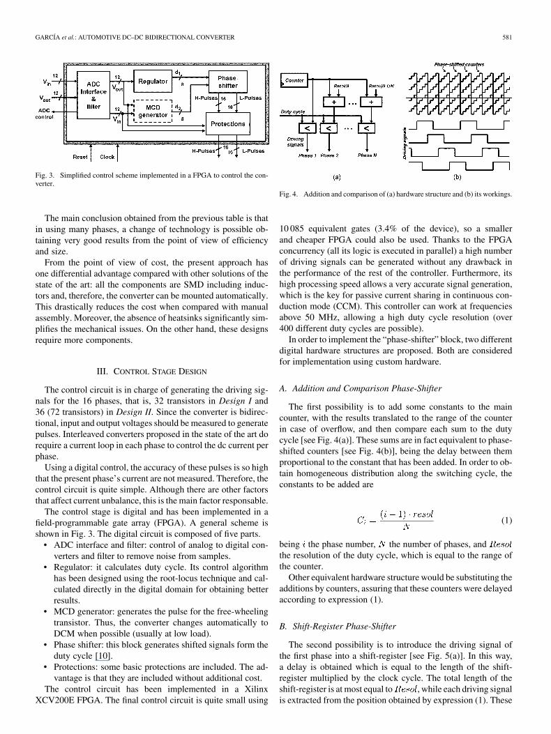
The first possibility is to add some constants to the maincounter, with the results translated to the range of the counterin case of overflow, and then compare each sum to the dutycycle [see Fig. 4(a)]. These sums are in fact equivalent to phase-shifted counters [see Fig. 4(b)], being the delay between themproportional to the constant that has been added. In order to ob-tain homogeneous distribution along the switching cycle, theconstants to be added are
(1)
being the phase number, the number of phases, andthe resolution of the duty cycle, which is equal to the range ofthe counter.
Other equivalent hardware structure would be substituting theadditions by counters, assuring that these counters were delayedaccording to expression (1).
B. Shift-Register Phase-Shifter
The second possibility is to introduce the driving signal ofthe first phase into a shift-register [see Fig. 5(a)]. In this way,a delay is obtained which is equal to the length of the shift-register multiplied by the clock cycle. The total length of theshift-register is at most equal to , while each driving signalis extracted from the position obtained by expression (1). These

582 IEEE TRANSACTIONS ON POWER ELECTRONICS, VOL. 21, NO. 3, MAY 2006
Fig. 5. (a) Shift-register hardware structure and (b) its workings.
delays are equivalent to the desired phase-shifting operation [seeFig. 5(b)].
C. Phase-Shifters Comparison
Three comparison criteria can be used to distinguish betweenthese two solutions.
• Duty cycle resolution. The shift-register method leads toshorter critical paths. Therefore, higher clock frequencycan be achieved and, as a consequence, duty cycle reso-lution can be increased.
• Closed-loop dynamics. Using addition and compar-ison phase-shifters, duty cycle changes start affectingall driving signals immediately, while for shift-registerphase-shifters these changes only affect the first phaseimmediately. The rest of the phases are affected only aftera time equal to their delay. Therefore, somewhat higherclosed-loop dynamics is achieved with the addition andcomparison method.
• Area. The addition and comparison phase-shifter is verysensitive to the number of phases, as each phase needs itsown adder and comparator. The shift-register phase-shifteris not sensitive to the number of phases, as including morephases needs is just extracting more driving signals fromthe already available shift-register. However, it is sensitiveto the duty cycle resolution, as the length of the shift-reg-ister is proportional to it.
IV. CURRENT SHARING
One of the concerns of the interleaved converters is currentsharing. Commercial integrated circuits solve this problem byincluding an additional current loop [11], [12]. As a conse-quence, the cost of the IC is quite high. Also, the additionalcircuitry grows, increasing size and decreasing reliability.Therefore, although the aforementioned IC controllers havebeen designed with the capability of paralleling some of them,in practice, a high number of phases is not feasible.
The purpose of this paper is to use a high number of phasesbut without any current loop. The dc current depends stronglyon the conduction mode of the converter.
A. Continuous Conduction Mode (CCM)
Fig. 6 shows the equivalent dc circuit of a multiphase buckconverter when it operates in CCM. Each phase is characterizedby a dc parasitic resistance ; the voltage applied to this re-
Fig. 6. Equivalent dc circuit of the multiphase buck converter working in CCM.
sistance is the input voltage multiplied by the actual dutycycle of this phase .
In case of passive load , the output voltage of the con-verter can be calculated from the aforementioned param-eters ( , , and ) with the following expression:
(2)
Note that if the load is a battery, the output voltage is justthe battery voltage and (2) is not used. Once is known, thecurrent through each phase is easily calculated
(3)
The worst-case for a single phase takes place when this phasehas the maximum duty cycle and the minimum resistance whilethe rest have minimum duty cycle and maximum resistance.In such a case, the phase current is maximum while the otherphases will handle a current below the average value . Inorder to determine which of both factors (differences in dutycycle or in resistance) is the most important, we can analyzeeach one independently. This analysis can be found in detail in[13], but the main results are the following ones. The differencescaused by resistance unbalance when only one resistance is dif-ferent from the others can be calculated as shown in
(4)
being the common resistance for the rest of the phases andthe difference in the unbalanced resistance. On the other
hand, the differences caused by duty cycle unbalance when onlyone duty cycle is different from the others can be calculated asshown in
(5)
being the common duty cycle for the rest of the phases,the difference in the unbalanced duty cycle, and the powerefficiency due to losses on the resistance exclusively.
GARCÍA et al.: AUTOMOTIVE DC–DC BIDIRECTIONAL CONVERTER 583
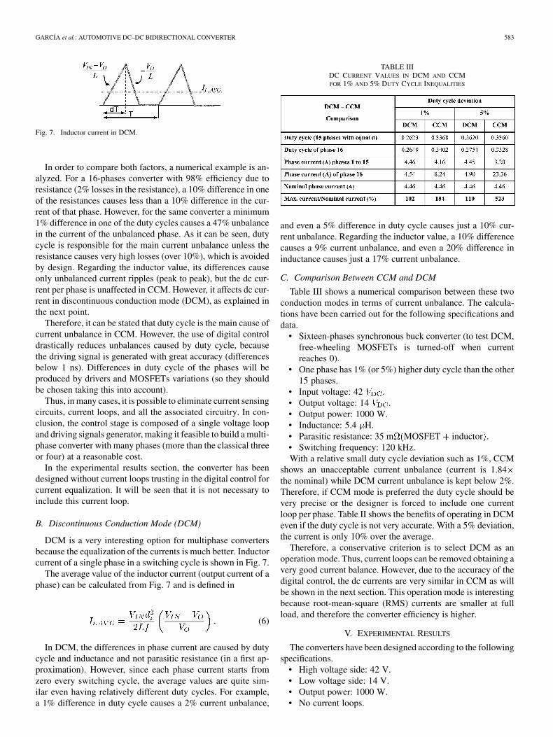
Fig. 7. Inductor current in DCM.
In order to compare both factors, a numerical example is an-alyzed. For a 16-phases converter with 98% efficiency due toresistance (2% losses in the resistance), a 10% difference in oneof the resistances causes less than a 10% difference in the cur-rent of that phase. However, for the same converter a minimum1% difference in one of the duty cycles causes a 47% unbalancein the current of the unbalanced phase. As it can be seen, dutycycle is responsible for the main current unbalance unless theresistance causes very high losses (over 10%), which is avoidedby design. Regarding the inductor value, its differences causeonly unbalanced current ripples (peak to peak), but the dc cur-rent per phase is unaffected in CCM. However, it affects dc cur-rent in discontinuous conduction mode (DCM), as explained inthe next point.
Therefore, it can be stated that duty cycle is the main cause ofcurrent unbalance in CCM. However, the use of digital controldrastically reduces unbalances caused by duty cycle, becausethe driving signal is generated with great accuracy (differencesbelow 1 ns). Differences in duty cycle of the phases will beproduced by drivers and MOSFETs variations (so they shouldbe chosen taking this into account).
Thus, in many cases, it is possible to eliminate current sensingcircuits, current loops, and all the associated circuitry. In con-clusion, the control stage is composed of a single voltage loopand driving signals generator, making it feasible to build a multi-phase converter with many phases (more than the classical threeor four) at a reasonable cost.
In the experimental results section, the converter has beendesigned without current loops trusting in the digital control forcurrent equalization. It will be seen that it is not necessary toinclude this current loop.
B. Discontinuous Conduction Mode (DCM)
DCM is a very interesting option for multiphase convertersbecause the equalization of the currents is much better. Inductorcurrent of a single phase in a switching cycle is shown in Fig. 7.
The average value of the inductor current (output current of aphase) can be calculated from Fig. 7 and is defined in
(6)
In DCM, the differences in phase current are caused by dutycycle and inductance and not parasitic resistance (in a first ap-proximation). However, since each phase current starts fromzero every switching cycle, the average values are quite sim-ilar even having relatively different duty cycles. For example,a 1% difference in duty cycle causes a 2% current unbalance,
TABLE IIIDC CURRENT VALUES IN DCM AND CCMFOR 1% AND 5% DUTY CYCLE INEQUALITIES
and even a 5% difference in duty cycle causes just a 10% cur-rent unbalance. Regarding the inductor value, a 10% differencecauses a 9% current unbalance, and even a 20% difference ininductance causes just a 17% current unbalance.
C. Comparison Between CCM and DCM
Table III shows a numerical comparison between these twoconduction modes in terms of current unbalance. The calcula-tions have been carried out for the following specifications anddata.
• Sixteen-phases synchronous buck converter (to test DCM,free-wheeling MOSFETs is turned-off when currentreaches 0).
• One phase has 1% (or 5%) higher duty cycle than the other15 phases.
• Input voltage: 42 .• Output voltage: 14 .• Output power: 1000 W.• Inductance: 5.4 H.• Parasitic resistance: 35 m MOSFET inductor .• Switching frequency: 120 kHz.With a relative small duty cycle deviation such as 1%, CCM
shows an unacceptable current unbalance (current is 1.84the nominal) while DCM current unbalance is kept below 2%.Therefore, if CCM mode is preferred the duty cycle should bevery precise or the designer is forced to include one currentloop per phase. Table II shows the benefits of operating in DCMeven if the duty cycle is not very accurate. With a 5% deviation,the current is only 10% over the average.
Therefore, a conservative criterion is to select DCM as anoperation mode. Thus, current loops can be removed obtaining avery good current balance. However, due to the accuracy of thedigital control, the dc currents are very similar in CCM as willbe shown in the next section. This operation mode is interestingbecause root-mean-square (RMS) currents are smaller at fullload, and therefore the converter efficiency is higher.
V. EXPERIMENTAL RESULTS
The converters have been designed according to the followingspecifications.
• High voltage side: 42 V.• Low voltage side: 14 V.• Output power: 1000 W.• No current loops.

584 IEEE TRANSACTIONS ON POWER ELECTRONICS, VOL. 21, NO. 3, MAY 2006
Fig. 8. Current ripple per phase in Design I.
Fig. 9. Measured efficiency of Design I as a function of the output current.
• Digital control, implemented in an FPGA.Two designs have been carried out. Design I with 16 phases
and Design II with 36.
A. Design I
Main characteristics of this prototype are as follows.• Number of phases: 16.• Power per phase: 62.5 W.• Phase switching frequency: 150 kHz.• Inductor per phase: 5.4 H (RM7).• MOSFETs: SI4450DY (SO-8 package).• Driver: IR2181S (2 drivers in a SO-8 package).The current per phase at full load is shown in Fig. 8. It can
be seen that the current ripple is high enough to achieve zero-voltage switcing (ZVS) in both transitions. In these conditions,the efficiency is maximum (it has been experimentally checked[14]) and a good current balance is achieved. This prototype hasbeen tested in CCM and DCM to see the performance aboutcurrent unbalance [15]. The main conclusion is that DCM ismuch better than CCM but, thanks to the accuracy of the digitalcontrol, the equilibrium in CCM is quite good.
Fig. 10. Prototype made with 16 phases: (a) single phase power stage and (b)whole power stage.
The efficiency of the converter is shown in Fig. 9. Maximumvalue is 95% at full load. No heatsink is used at room tempera-ture.
Finally, Fig. 10 shows two pictures of the power stage of theconverter. The main characteristic is that it has been possibleto use low profile components obtaining a 10-mm height and1000-W converter (tallest component is an RM7 core embebbedin the PCB).
B. Design II
The main characteristics of this prototype are as follows.• Number of phases: 36.• Power per phase: 27.7 W.• Phase switching frequency: 100 kHz.• Inductor per phase: 47 H (WE PD-47).• MOSFETs: IRF7341 (two transistors in a SO-8 package).• Driver: IR2181S (two drivers in a SO-8 package).Compared with the previously presented prototype, the main
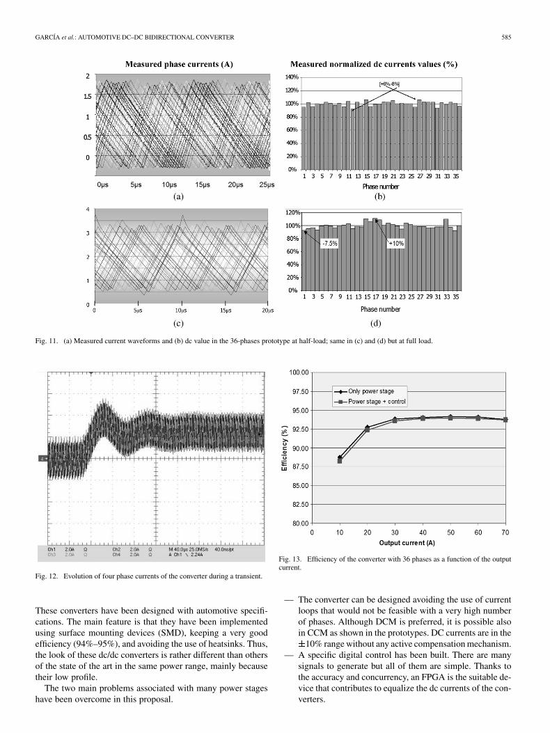
difference is that this design runs in CCM but with positive cur-rent (current ripple is small compared to the dc current value).In these conditions, the dc current through each phase is onlydefined by the parasitic resistances and duty cycle inequalities[see (3)]. Measured current waveforms in steady-state condi-tions are shown in Fig. 11(a) and (c). Although no current loopshave been used, dc currents through each phase are quite sim-ilar even during transients as shown in Fig. 12 (only four phasecurrents are shown). All of them are in the range 10% at fullload. Fig. 11(b) and (d) shows the dc phase current values.
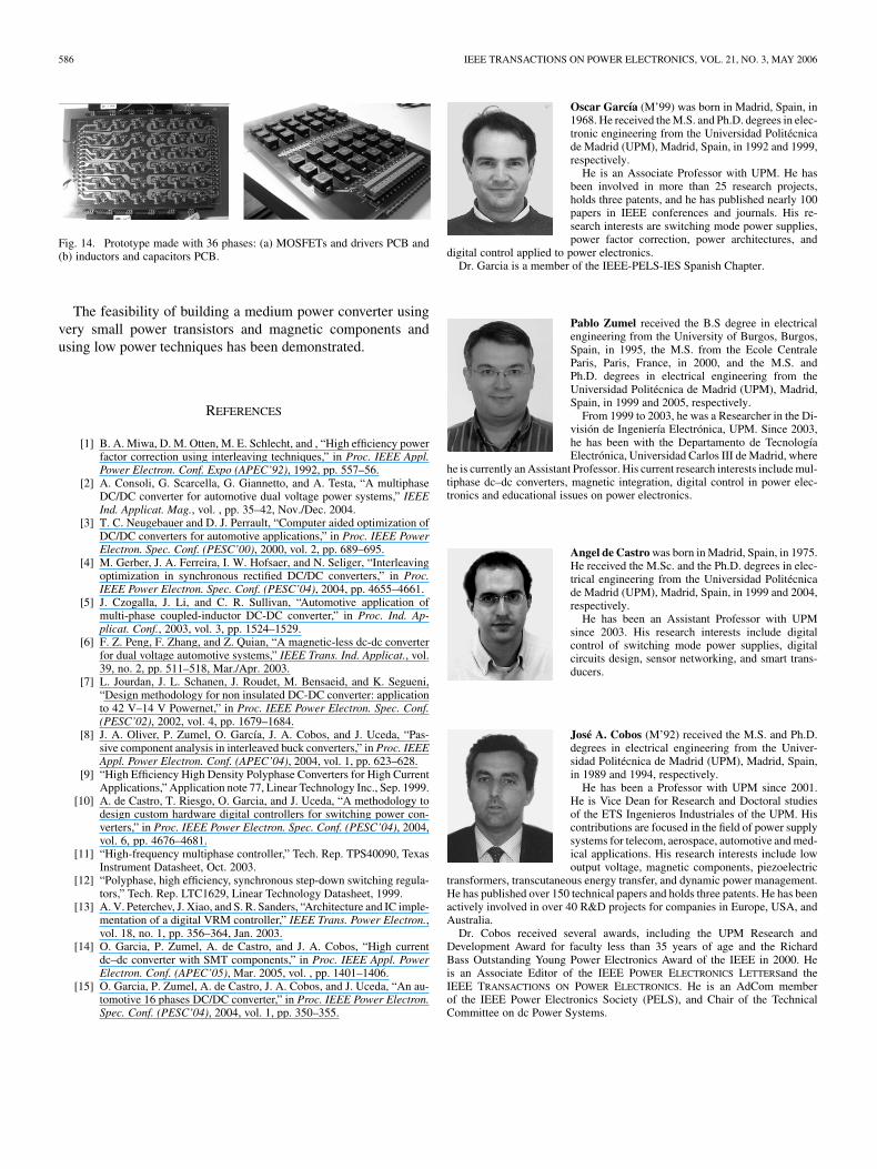
Design II has a maximum efficiency of 94% with 50 A and93.5% at full load as shown in Fig. 13. A converter with 36phases is shown in Fig. 14. The converter is composed of twostacked PCBs with a pair of connectors between. The first PCBcontains the power transistors (on the top side) and the drivers(bottom side); the second PCB includes the inductors and theoutput capacitors.
VI. CONCLUSION
The interleaving technique has several advantages such as fil-ters reduction, better dynamic response, and better thermal man-agement. Besides the classical approach, using a high numberof phases brings other advantages. In particular, power compo-nents can be SMD and/or inductors can be integrated in the PCB.Thus, the converter is repetitivity increased, the assembly can beautomatic, and even heatsinks can be removed.
In this paper, two multiphase 1000-W dc–dc converters madeof many interleaved buck phases (16 and 36) are proposed.
GARCÍA et al.: AUTOMOTIVE DC–DC BIDIRECTIONAL CONVERTER 585
Fig. 11. (a) Measured current waveforms and (b) dc value in the 36-phases prototype at half-load; same in (c) and (d) but at full load.
Fig. 12. Evolution of four phase currents of the converter during a transient.
These converters have been designed with automotive specifi-cations. The main feature is that they have been implementedusing surface mounting devices (SMD), keeping a very goodefficiency (94%–95%), and avoiding the use of heatsinks. Thus,the look of these dc/dc converters is rather different than othersof the state of the art in the same power range, mainly becausetheir low profile.
The two main problems associated with many power stageshave been overcome in this proposal.
Fig. 13. Efficiency of the converter with 36 phases as a function of the outputcurrent.
— The converter can be designed avoiding the use of currentloops that would not be feasible with a very high numberof phases. Although DCM is preferred, it is possible alsoin CCM as shown in the prototypes. DC currents are in the
10% range without any active compensation mechanism.— A specific digital control has been built. There are many
signals to generate but all of them are simple. Thanks tothe accuracy and concurrency, an FPGA is the suitable de-vice that contributes to equalize the dc currents of the con-verters.
586 IEEE TRANSACTIONS ON POWER ELECTRONICS, VOL. 21, NO. 3, MAY 2006
Fig. 14. Prototype made with 36 phases: (a) MOSFETs and drivers PCB and(b) inductors and capacitors PCB.
The feasibility of building a medium power converter usingvery small power transistors and magnetic components andusing low power techniques has been demonstrated.
REFERENCES
[1] B. A. Miwa, D. M. Otten, M. E. Schlecht, and , “High efficiency powerfactor correction using interleaving techniques,” in Proc. IEEE Appl.Power Electron. Conf. Expo (APEC’92), 1992, pp. 557–56.
[2] A. Consoli, G. Scarcella, G. Giannetto, and A. Testa, “A multiphaseDC/DC converter for automotive dual voltage power systems,” IEEEInd. Applicat. Mag., vol. , pp. 35–42, Nov./Dec. 2004.
[3] T. C. Neugebauer and D. J. Perrault, “Computer aided optimization ofDC/DC converters for automotive applications,” in Proc. IEEE PowerElectron. Spec. Conf. (PESC’00), 2000, vol. 2, pp. 689–695.
[4] M. Gerber, J. A. Ferreira, I. W. Hofsaer, and N. Seliger, “Interleavingoptimization in synchronous rectified DC/DC converters,” in Proc.IEEE Power Electron. Spec. Conf. (PESC’04), 2004, pp. 4655–4661.
[5] J. Czogalla, J. Li, and C. R. Sullivan, “Automotive application ofmulti-phase coupled-inductor DC-DC converter,” in Proc. Ind. Ap-plicat. Conf., 2003, vol. 3, pp. 1524–1529.
[6] F. Z. Peng, F. Zhang, and Z. Quian, “A magnetic-less dc-dc converterfor dual voltage automotive systems,” IEEE Trans. Ind. Applicat., vol.39, no. 2, pp. 511–518, Mar./Apr. 2003.
[7] L. Jourdan, J. L. Schanen, J. Roudet, M. Bensaeid, and K. Segueni,“Design methodology for non insulated DC-DC converter: applicationto 42 V–14 V Powernet,” in Proc. IEEE Power Electron. Spec. Conf.(PESC’02), 2002, vol. 4, pp. 1679–1684.
[8] J. A. Oliver, P. Zumel, O. García, J. A. Cobos, and J. Uceda, “Pas-sive component analysis in interleaved buck converters,” in Proc. IEEEAppl. Power Electron. Conf. (APEC’04), 2004, vol. 1, pp. 623–628.
[9] “High Efficiency High Density Polyphase Converters for High CurrentApplications,” Application note 77, Linear Technology Inc., Sep. 1999.
[10] A. de Castro, T. Riesgo, O. Garcia, and J. Uceda, “A methodology todesign custom hardware digital controllers for switching power con-verters,” in Proc. IEEE Power Electron. Spec. Conf. (PESC’04), 2004,vol. 6, pp. 4676–4681.
[11] “High-frequency multiphase controller,” Tech. Rep. TPS40090, TexasInstrument Datasheet, Oct. 2003.
[12] “Polyphase, high efficiency, synchronous step-down switching regula-tors,” Tech. Rep. LTC1629, Linear Technology Datasheet, 1999.
[13] A. V. Peterchev, J. Xiao, and S. R. Sanders, “Architecture and IC imple-mentation of a digital VRM controller,” IEEE Trans. Power Electron.,vol. 18, no. 1, pp. 356–364, Jan. 2003.
[14] O. Garcia, P. Zumel, A. de Castro, and J. A. Cobos, “High currentdc–dc converter with SMT components,” in Proc. IEEE Appl. PowerElectron. Conf. (APEC’05), Mar. 2005, vol. , pp. 1401–1406.
[15] O. Garcia, P. Zumel, A. de Castro, J. A. Cobos, and J. Uceda, “An au-tomotive 16 phases DC/DC converter,” in Proc. IEEE Power Electron.Spec. Conf. (PESC’04), 2004, vol. 1, pp. 350–355.
Oscar García (M’99) was born in Madrid, Spain, in1968. He received the M.S. and Ph.D. degrees in elec-tronic engineering from the Universidad Politécnicade Madrid (UPM), Madrid, Spain, in 1992 and 1999,respectively.
He is an Associate Professor with UPM. He hasbeen involved in more than 25 research projects,holds three patents, and he has published nearly 100papers in IEEE conferences and journals. His re-search interests are switching mode power supplies,power factor correction, power architectures, and
digital control applied to power electronics.Dr. Garcia is a member of the IEEE-PELS-IES Spanish Chapter.
Pablo Zumel received the B.S degree in electricalengineering from the University of Burgos, Burgos,Spain, in 1995, the M.S. from the Ecole CentraleParis, Paris, France, in 2000, and the M.S. andPh.D. degrees in electrical engineering from theUniversidad Politécnica de Madrid (UPM), Madrid,Spain, in 1999 and 2005, respectively.
From 1999 to 2003, he was a Researcher in the Di-visión de Ingeniería Electrónica, UPM. Since 2003,he has been with the Departamento de TecnologíaElectrónica, Universidad Carlos III de Madrid, where
he is currently an Assistant Professor. His current research interests include mul-tiphase dc–dc converters, magnetic integration, digital control in power elec-tronics and educational issues on power electronics.
Angel de Castro was born in Madrid, Spain, in 1975.He received the M.Sc. and the Ph.D. degrees in elec-trical engineering from the Universidad Politécnicade Madrid (UPM), Madrid, Spain, in 1999 and 2004,respectively.
He has been an Assistant Professor with UPMsince 2003. His research interests include digitalcontrol of switching mode power supplies, digitalcircuits design, sensor networking, and smart trans-ducers.
José A. Cobos (M’92) received the M.S. and Ph.D.degrees in electrical engineering from the Univer-sidad Politécnica de Madrid (UPM), Madrid, Spain,in 1989 and 1994, respectively.
He has been a Professor with UPM since 2001.He is Vice Dean for Research and Doctoral studiesof the ETS Ingenieros Industriales of the UPM. Hiscontributions are focused in the field of power supplysystems for telecom, aerospace, automotive and med-ical applications. His research interests include lowoutput voltage, magnetic components, piezoelectric
transformers, transcutaneous energy transfer, and dynamic power management.He has published over 150 technical papers and holds three patents. He has beenactively involved in over 40 R&D projects for companies in Europe, USA, andAustralia.
Dr. Cobos received several awards, including the UPM Research andDevelopment Award for faculty less than 35 years of age and the RichardBass Outstanding Young Power Electronics Award of the IEEE in 2000. Heis an Associate Editor of the IEEE POWER ELECTRONICS LETTERSand theIEEE TRANSACTIONS ON POWER ELECTRONICS. He is an AdCom memberof the IEEE Power Electronics Society (PELS), and Chair of the TechnicalCommittee on dc Power Systems.
Related Documents

![HIGH-CONVERSION-RATIO BIDIRECTIONAL DC–DC ......bidirectional dc –dc converter with a high convention ratio is a key component of battery applications [5] Isolated bidirectional](https://static.cupdf.com/doc/110x72/5f0a32787e708231d42a7b2d/high-conversion-ratio-bidirectional-dcadc-bidirectional-dc-adc-converter.jpg)