Automation of Shoe Last Modification and Tool Path Planning by Samuel J. Lochner A thesis presented to the University of Waterloo in fulfillment of the thesis requirement for the degree of Master of Applied Science in Mechanical Engineering Waterloo, Ontario, Canada, 2009 ©Samuel J. Lochner 2009

Welcome message from author
This document is posted to help you gain knowledge. Please leave a comment to let me know what you think about it! Share it to your friends and learn new things together.
Transcript

Automation of Shoe Last Modification and
Tool Path Planning
by
Samuel J. Lochner
A thesis
presented to the University of Waterloo
in fulfillment of the
thesis requirement for the degree of
Master of Applied Science
in
Mechanical Engineering
Waterloo, Ontario, Canada, 2009
©Samuel J. Lochner 2009

ii
AUTHOR'S DECLARATION
I hereby declare that I am the sole author of this thesis. This is a true copy of the thesis, including any
required final revisions, as accepted by my examiners.
I understand that my thesis may be made electronically available to the public.

iii
Abstract
To make mass production of footwear a viable operation for manufacturers and retailers, the number
of sizes per model must be optimized. For this reason, manufacturers generally only scale designs by
length and width measurements. The human foot, however, is a complex and flexible 3D shape that
varies greatly from individual to individual. Slight irregularities or foot deformations will result in ill
fitting footwear and over time may result in injuries. Custom made shoes are available however the
price is often in excess of $2000 CAN. For the majority of individuals without insurance, this price is
not practical.
Custom footwear production is expensive primarily because of the challenges of custom shoe last
production. A shoe last is basically a model of the foot that has undergone various simplifications
and modifications to provide a more aesthetic and functional mold about which to build the shoe
whilst maintaining the primary geometrical characteristics of the foot. For custom shoes, a custom
last is made for each foot.
Techniques for creating a custom last vary greatly. In some cases modern digitizing equipment,
computer numerically controlled (CNC) milling machines, computer aided design (CAD) software,
and computer aided manufacturing (CAM) software is used to create the last. In other cases,
traditional manual techniques are used. It should be expected that modern techniques, due to
automation, would require far less skilled labor than traditional techniques; however this is not the
case. Clearly the available modern systems must be deficient in some respect.
After reviewing the various modern systems available, it was determined that the primary source for
skilled labor requirement was the last design software, often taking an operator an hour per custom
last to design. The primary problem identified with the software reviewed was lack of automation.
Another drawback was that the software did not properly take advantage of the concept of a virtual fit
(the foot model is placed inside the last as if trying on the shoe). A third problem was that feet of all
types were dealt with in the same manner. This is inadequate because a foot with major deformities
will require different tools than a foot that can be adequately fit with simple last measurement
adjustments.

iv
The focus of this project is to create an improved system for custom last production that addresses the
above issues. Tools for adjusting feet to the proper position for fitting in a shoe were provided. Last
measurements were made relative to the foot‟s critical points to better quantify the quality of fit for a
particular foot.
Algorithms were created to design lasts automatically for feet that are irregular in measurements but
do not exhibit major deformities. For feet that do not fall into this category, lasts are initially designed
using the automatic techniques and then manual techniques are provided for further customization as
needed. Methods were also developed for creating tool paths to guide CNC milling machines to
create the lasts.
The system was tested for 3 different feet of similar sizes. In parallel, a custom manufacturer created
3 lasts for the same feet using traditional methods. The automatically modified lasts and the manually
modified lasts were compared. Unfortunately, the digitizing methods used to obtain models of the feet
were inaccurate. As a result, the automatically modified lasts differed significantly from the manually
modified lasts. This comparison aside however, the automatic algorithms achieved their goal of
modifying a last such that its measurements matched recommended measurements with an average
error of less than 2mm.
In conclusion, a shoe last for a foot without major deformities can be modified so that its
measurements match those of recommended measurements. As long as the starting last is of an
appropriate style for the intended foot, this should (in theory) create a last that can be used to make a
shoe that is comfortable and orthopedically appropriate while maintaining the style and smoothness of
the original last. The system requires a minimum amount of user input, thus greatly simplifying the
last creation process and reducing the price of custom shoe production. The next step is to further test
the system for lasts of all sizes and create footwear from the resulting shoe lasts.

v
Acknowledgements
I would like to acknowledge Professor Sanjeev Bedi for his wisdom and guidance, Tezera Ketema for
his knowledge and encouragement, and Professor Jan Huisson and Ray Bauman for their
contribution.

vi
Table of Contents
List of Figures ..................................................................................................................................... viii
Chapter 1 Introduction ............................................................................................................................ 1
1.1 Modern Improvements to Traditional Techniques ....................................................................... 3
1.1.1 Digitizing the Foot ................................................................................................................. 5
1.1.2 Measuring the Foot ................................................................................................................ 7
1.1.3 Modifying the Last ................................................................................................................ 7
1.1.4 Fabricating the Shoe .............................................................................................................. 8
1.2 Custom Last Design Program Deficiencies .................................................................................. 8
1.2.1 Measuring Deficiencies ......................................................................................................... 8
1.2.2 Last Modification Deficiency ................................................................................................ 9
1.3 Commercial Solutions ................................................................................................................ 10
1.3.1 Shoemaster .......................................................................................................................... 10
1.3.2 Ideas Foot CAD ................................................................................................................... 11
1.3.3 Precision 3D ........................................................................................................................ 12
Chapter 2 Foot Definitions and Conditions .......................................................................................... 13
2.1.1 Landmarks ........................................................................................................................... 13
2.1.2 Axis ..................................................................................................................................... 14
2.1.3 Measurements ...................................................................................................................... 15
2.2 Common Foot Conditions .......................................................................................................... 18
Chapter 3 Project Goals ........................................................................................................................ 21
Chapter 4 Implementation .................................................................................................................... 23
4.1 Preliminary Decisions ................................................................................................................ 23
4.1.1 Choosing Rhinoceros 3D ..................................................................................................... 23
4.1.2 Mesh or Surface ................................................................................................................... 26
4.2 Proposed System ........................................................................................................................ 27
4.2.1 Adjusting the Foot ............................................................................................................... 28
4.2.2 Determine Critical Points .................................................................................................... 29
4.2.3 Orienting the Foot................................................................................................................ 31
4.2.4 Taking Measurements ......................................................................................................... 32
4.2.5 Last Alignment .................................................................................................................... 39
4.2.6 Last Measurement ............................................................................................................... 39

vii
4.2.7 Automatic Last fitting .......................................................................................................... 41
4.3 Alternative Automatic Modification .......................................................................................... 45
4.3.1 Global Control Point Modification ...................................................................................... 45
4.3.2 Global Cage Point Modification .......................................................................................... 46
4.3.3 Flow for Girth Changes ....................................................................................................... 46
4.4 Manual Modification .................................................................................................................. 48
4.5 Tool path Planning ..................................................................................................................... 49
4.5.1 Normal Tool Radius Offset ................................................................................................. 51
4.5.2 Offset Mesh ......................................................................................................................... 52
4.5.3 Part Fixturing ....................................................................................................................... 52
Chapter 5 Testing and Results .............................................................................................................. 53
5.1 Test 1 .......................................................................................................................................... 53
5.2 Test 2 .......................................................................................................................................... 55
5.3 Test 3 .......................................................................................................................................... 57
5.4 Tool path Planning Results ......................................................................................................... 58
5.4.1 Offset Mesh Tool path Planning Results ............................................................................. 58
5.4.2 Tool Radius Offset Tool Path Planning Results .................................................................. 58
Chapter 6 Conclusion ........................................................................................................................... 60
Chapter 7 Recommendations ................................................................................................................ 62
Appendices ........................................................................................................................................... 64
Appendix A Structure of the Foot .................................................................................................... 64
Appendix B Measuring the Foot ...................................................................................................... 66
Appendix C Required Modifications ................................................................................................ 67
Bibliography ......................................................................................................................................... 70

viii
List of Figures
Figure 1-1 Algorithms from left to right: Traditional Techniques, Modern Techniques, Ideal Modern
Techniques.............................................................................................................................................. 4
Figure 1-2 from left to right: Shoemaster Laser Scanner [11], Precision 3D Pattern Projection System
[12], Ideas Pattern Projection System With Foam Impression Scanner [13] ....................................... 11
Figure 2-1 Foot Landmarks .................................................................................................................. 14
Figure 2-2 Brannock and Second Toe Axes ......................................................................................... 15
Figure 2-3 Measurements in Top View ................................................................................................ 17
Figure 2-4 Girths .................................................................................................................................. 18
Figure 2-5 From left to right: Hammer Toe, Morton‟s Neuroma, Heel Pain, Corns and Calluses,
Hallux Valgus [15] ............................................................................................................................... 20
Figure 4-1 Axes Labeling ..................................................................................................................... 24
Figure 4-2 Creating girth curve by projecting perpendicular to the yz-plane ...................................... 24
Figure 4-3 Using Flow Operation to Match Girth Curve ..................................................................... 25
Figure 4-4 Heel Height Changed With Cage Edit Function ................................................................. 25
Figure 4-5 From Left to Right: Mesh, Single Surface, Three Surface Last ......................................... 26
Figure 4-6 Flow chart for proposed system .......................................................................................... 28
Figure 4-7 from left to right: Flat, Toespring Added, Heel Height Added, Mid Section Adjusted ..... 29
Figure 4-8 Locating MPJ points ........................................................................................................... 30
Figure 4-9 Locating Instep Point .......................................................................................................... 30
Figure 4-10 Locating Second_toe_xy, Heel_point_xy, and Heel_point_pulled .................................. 31
Figure 4-11 Orienting the foot .............................................................................................................. 32
Figure 4-12 Determining Heel Width ................................................................................................... 34
Figure 4-13 Determining Waist Width ................................................................................................. 34
Figure 4-14 Determining Heel and Toe Height .................................................................................... 35
Figure 4-15 Convex Hull ...................................................................................................................... 37
Figure 4-16 Determining Ball Girth Curve .......................................................................................... 37
Figure 4-17 Determining Instep Girth .................................................................................................. 38
Figure 4-18 Determining Waist Girth .................................................................................................. 39
Figure 4-19 Determining Long Heel Girth ........................................................................................... 39
Figure 4-20 Instep_Heel_Point lines .................................................................................................... 40
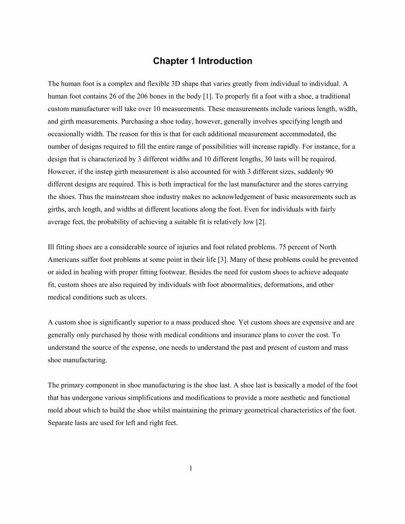
Figure 4-21 Before and After Length Scaling ...................................................................................... 42

ix
Figure 4-22 Before and After Ball Line Matching ............................................................................... 43
Figure 4-23 The Highlighted Points are used to Modify Heel Width .................................................. 44
Figure 4-24 Cage Points used for Ball and Waist Girth Modifications ................................................ 44
Figure 4-25 Cage Points used for Instep and Long Heel Girth Modifications ..................................... 45
Figure 4-26 Girth Curve Scaling for Flow Modification ..................................................................... 47
Figure 4-27 Manual Modification with Cage Edit Function ................................................................ 49
Figure 4-28 Manual Modification of Cross Section using Cage Edit Locally ..................................... 49
Figure 4-29 Corkscrew intersected with last to create spiral path ........................................................ 50
Figure 4-30 From left to right: Tool contacting surface with radius greater than tool radius, tool
contacting surface where secondary surface causes gouge, tool contacting surface where radius is less
than tool radius causing gouge ............................................................................................................. 51
Figure 4-31 Fixturing Cylinder Location ............................................................................................. 52
Figure 5-1 Test 1 Results ...................................................................................................................... 54
Figure 5-2 Test 1 Before and After Automatic Modifications ............................................................. 54
Figure 5-3 Test 2 Results ...................................................................................................................... 55
Figure 5-4 Test 2 Before and After Automatic Modification ............................................................... 56
Figure 5-5 Test 3 Results ...................................................................................................................... 57
Figure 5-6 Test 3 Before and After Automatic Modification ............................................................... 57
Figure 5-7 Offset Mesh Tool path ........................................................................................................ 58
Figure 5-8 Gouge Near Fixturing Cylinder .......................................................................................... 59
Figure 5-9 Tool Radius Offset Tool path VS Offset Surface Tool path ............................................... 59
1
Chapter 1 Introduction
The human foot is a complex and flexible 3D shape that varies greatly from individual to individual. A
human foot contains 26 of the 206 bones in the body [1]. To properly fit a foot with a shoe, a traditional
custom manufacturer will take over 10 measurements. These measurements include various length, width,
and girth measurements. Purchasing a shoe today, however, generally involves specifying length and
occasionally width. The reason for this is that for each additional measurement accommodated, the
number of designs required to fill the entire range of possibilities will increase rapidly. For instance, for a
design that is characterized by 3 different widths and 10 different lengths, 30 lasts will be required.
However, if the instep girth measurement is also accounted for with 3 different sizes, suddenly 90
different designs are required. This is both impractical for the last manufacturer and the stores carrying
the shoes. Thus the mainstream shoe industry makes no acknowledgement of basic measurements such as
girths, arch length, and widths at different locations along the foot. Even for individuals with fairly
average feet, the probability of achieving a suitable fit is relatively low [2].
Ill fitting shoes are a considerable source of injuries and foot related problems. 75 percent of North
Americans suffer foot problems at some point in their life [3]. Many of these problems could be prevented
or aided in healing with proper fitting footwear. Besides the need for custom shoes to achieve adequate
fit, custom shoes are also required by individuals with foot abnormalities, deformations, and other
medical conditions such as ulcers.
A custom shoe is significantly superior to a mass produced shoe. Yet custom shoes are expensive and are
generally only purchased by those with medical conditions and insurance plans to cover the cost. To
understand the source of the expense, one needs to understand the past and present of custom and mass
shoe manufacturing.
The primary component in shoe manufacturing is the shoe last. A shoe last is basically a model of the foot
that has undergone various simplifications and modifications to provide a more aesthetic and functional
mold about which to build the shoe whilst maintaining the primary geometrical characteristics of the foot.
Separate lasts are used for left and right feet.

2
Traditionally, a shoe last was made of wood. It was shaped using various carving techniques and
measurements were made with calipers, measuring sticks, and measuring tape. The last was modified
until the desired measurements were reached.
The last was used as a template for cutting the sole and upper materials. The sole and upper would then be
connected to the last with small nails. The sole and upper could then be sewn together. Afterwards, the
last was removed from the shoe. Often, lasts were reused; however, it was not uncommon to have a
custom last for a single customer. The manufacturing process for a custom shoe and a standard sized shoe
varied little.
Over time, custom manufacturing and standard manufacturing branched apart. While custom
manufacturing continued to use traditional manual techniques, standard manufacturing began to make use
of developing technology. In particular, the injection molding machine and the development of synthetic
materials decreased manufacturing time and cost while increasing manufacturing consistency. The advent
of computerized systems had a tremendous impact on automating the manufacturing process.
Despite technological advancements, mass shoe manufacturing remains a highly manual labor intensive
process. For this reason, nearly all mass shoe manufacturing has moved overseas where labor costs are
much lower.
Custom shoe manufacturing on the other hand, has for the most part remained a local but steadily
declining trade. This is primarily because it is still a finicky, trial and error process that often requires
mock fittings (prototype shoe with cheap materials and makeshift construction for testing purposes),
various adjustments after manufacture, as well as customer presence. An exception to being a local trade
is Otabo, a Florida based company that is currently attempting to scan feet at arbitrary locations, create
the last computer model at their location, have the last and shoe fabricated oversees, and ship the finished
pair of shoes to the customer. However, a large percentage of the shoes made in this manner require
rework.
To custom manufacture in nations with higher labor costs, automation technology must be used to reduce
the amount of skilled labor required. Various companies have devised solutions to this problem. Different
types of scanners, last milling machines, pattern cutting and sewing machines, and software packages

3
have been developed. Despite this, custom manufacturing is still extremely expensive, on the order of two
to three thousand dollars Canadian for a pair of custom shoes. Also, some manufactures prefer an entirely
manual process from last fabrication to pattern cutting and are able to remain competitive. This in itself is
a testament to the shortcomings of available modern custom shoe creation systems.
Creating an appropriate last model is the primary cause for lengthy design time and frequent rework. A
manufacturer using the Ideas system stated that it took between 2 and 3 hours to design a pair of lasts, and
even then a rework was often required. A custom last manufacturer using manual techniques said that it
took between 2 and 4 hours to make a pair of lasts, thus in some cases, the fully manual process is
actually shorter [4]. For this reason, the focus of this project is to improve the custom last design process.
1.1 Modern Improvements to Traditional Techniques
As explained above, the development of computerized systems in the last half century has allowed for the
development of new techniques for manufacturing custom shoes. Figure 1-1 provides flow charts for
manufacturing custom shoes using traditional manual techniques, common modern techniques, and ideal
modern techniques. For modern techniques, the „Measure Foot‟ step has been divided into 2 steps; „Scan
Foot‟, and „Measure Foot‟ [5][6]. These steps should theoretically take less time, require less skilled
labor, and yield more consistent and accurate results than the traditional „Measure Foot‟ step. Similarly,
the „Modify Physical Last‟ step has been divided into three steps: „Modify Last Model‟, ‟Tool Path
Planning‟, and „Machining‟. This change requires more steps on the flow chart; however, theoretically
this should involve drastically less skilled labor because all three steps except for „Modify Last Model‟
are completed automatically. It should also be noted that the „Build Shoe‟ step has also been impacted by
modern technology and as a result, a shoe can be built with far less manual labor.
The third flow chart in Figure 1-1 shows the ideal modern algorithm. The „Modify Last Model„ step for
the ideal modern algorithm should occur as automatically as possible, therefore greatly reducing the
amount of skilled labor required. Also, by removing the rework and trial fitting steps, the entire process is
greatly simplified; customers need only visit the scanning location once and far less skilled labor is
required. To make this possible, however, the „Modify Last Model‟ step must be greatly improved for
quality and automation.

4
Last modification is the area most in need of improvements and is the focus of this project. However, it is
also important to understand how modern technology has had an impact on other steps in the custom shoe
manufacturing process. The following sections provide information on modern improvements as well as
explanations on respective deficiencies.
Figure 1-1 Algorithms from left to right: Traditional Techniques, Modern Techniques, Ideal
Modern Techniques

5
1.1.1 Digitizing the Foot
There are many different techniques for obtaining the geometry of a foot. The most basic method uses a
tape measure to obtain the girths, a ruler to measure lengths, calipers to measure widths, and a trace to
obtain the shape. A variation on this method is to make a casting of the foot, thus allowing the last maker
to keep a copy of the foot for reference during last making. Traces, carbon prints, and foam impressions
of feet are also used to memorize the geometry.
With advances in scanning technology, it has become possible to make a computerized model of the foot.
Measurements can then be taken from the model, greatly simplifying the customers experience as well as
minimizing operator error.
Though designing scanning equipment is not a goal for this project, the 3D model quality and manner in
which the model is created will have a large impact on the results. For example, if the foot is scanned in a
loaded position rather than unloaded, then this must be taken into account when designing the last. For
this reason, it is important to review the different methods of obtaining a model of the foot. There is a
great variety of methods for obtaining 3D models of physical objects; however, only those commonly
used for digitizing feet will be covered. Casting and foam impressions are relatively old techniques,
however, they are used in conjunction with new technologies and thus will be discussed.
1.1.1.1 Casting
There are generally 2 types of casting methods; plaster casting, and fiberglass casting. Both have medical
origins being used for casting parts of the body to maintain specific orientation while healing. The
fiberglass cast has a thin consistent shell and thus with a small offset of the surface can provide a 3D
model of the foot. A plaster cast on the other hand is fairly thick with varying thickness and therefore a
material must be poured inside the cast to get an accurate and accessible representation of the foot. Both
methods involve obtaining geometry of the foot in unloaded positions. A deficiency in the process is that
the casting will be distorted when removed from the foot because it must be cut open and flexed to allow
the foot to exit. Casting may also distort the shape of the foot as it will apply some pressure on the foot,
perhaps reducing the length and causing other distortions. For the fiberglass cast, concave regions of the
foot like the arch area may not be accurately modeled as the cast will tend to sag. Despite the drawbacks
of casting, it is widely used because the operator does not require any expensive equipment; further

6
processing can be done at separate specialized locations by using the physical casting as a mold or
scanning it to create a computer model of the foot. An important advantage of casting is that the podiatrist
can manipulate the shape of the foot while casting so as to place it in an anatomically correct position.
1.1.1.2 Foam Impression
The foot is pressed into a foam tablet that „memorizes‟ the geometry of the bottom of the foot. This
technology is limited to only representing the bottom of the foot. Once the foam impression is made, the
foam tablets can be sent to another location to be scanned or used directly in the manufacture of orthotics.
Similar to casting, the shape of the foot can be manipulated while taking the impression. Opposite to
casting however, is that the material underneath the arch will tend to be too high rather than sag. This is
because the foam provides resistance as the foot is pushed into it, therefore forcing the more flexible
regions of the foot (in particular the arch) away from normal position. For this reason, operators are
compelled to manually modify the resulting impression by making an educated guess at the correct shape.
This may result in error.
1.1.1.3 Pattern Projection
Lines of high intensity focused light are projected onto the foot. A camera photographs the model at a
known angle. Triangulation is used to determine the geometry. By doing this on all sides of the foot, a 3D
model can be generated. Pattern projection is best suited for rooms with minimal other light source. The
foot cannot be manipulated during scanning. Pattern projection systems generally take a second set of
images without the pattern projection and thus pick up the texture of the model. The texture is combined
with the 3D model to create a fully textured 3D model. This added texture information can provide crucial
information such as location of ulcers and calluses.
1.1.1.4 Laser Scanning
The laser scanner operates similar to a standard document or photograph flatbed scanner where cameras
take pictures as they are moved incrementally by stepper motors. The primary difference is that a laser
line is also projected onto the foot at a known angle to the cameras. Triangulation is used to obtain the
geometry at each step. Several of these setups are oriented around the foot so as to create a full 3D model
of the foot. The foot rests partially or fully loaded on a glass plate, beneath which is one of the scanning

7
apparatuses. Lasers provide the advantage of being able to be identified by cameras in all common
lighting environments and provide excellent accuracy. Once again the foot cannot be manipulated during
scanning. Scan time is longer than pattern projection scanning and during this time the patient must
remain still. Similar to pattern projection systems, laser scanners are able to create a fully textured model.
1.1.2 Measuring the Foot
Traditional tools for measuring the foot include calipers, measuring tapes and measuring sticks. With a
computer model of the foot however, the foot can be measured in software. Some of the tools needed to
measure a complex 3D object are commonplace in computer aided design (CAD) programs. However,
more complex measurements such as girth measurements may require more specific CAD programs.
Many CAD programs are specifically designed for the application of measuring feet. Details on the
deficiencies of available systems can be found in section 1.2.
1.1.3 Modifying the Last
Traditionally, lasts would be made and modified by hand with tools such as chisels. With a CAD program
however, a model of the last can be modified as necessary before actually manufacturing. Last models are
created by modifying the geometry of existing lasts. Thus the use of CAD packages for last modification
did not take hold until digitizing solutions such as the laser scanner became available. Most modern CAD
programs are able to manipulate lasts by scaling and transformation. However, the tools required to adjust
a last to closely fit a foot are less common. For this reason, specialized CAD systems have been
developed to provide modern last makers with powerful last modification tools.
To create the physical last, computer aided manufacturing (CAM) packages are used to convert the CAD
model into numerically controlled (NC) code that will operate computer numerically controlled (CNC)
milling machines. The specialized CAD systems mentioned above often incorporate a CAM system to
provide a more streamlined solution.

8
Though these specialized CAD/CAM packages have been used to manufacture custom shoe lasts with
some degree of success, there are many critical flaws that leave custom shoe manufacturing an
excessively expensive endeavor.
1.1.4 Fabricating the Shoe
The shoe last provides a mold around which the shoe is built. Traditional shoe building requires an
enormous amount of manual labor; however, continued growth in the use of automation for procedures
such as pattern cutting has reduced the requirements for manual labor.
1.2 Custom Last Design Program Deficiencies
1.2.1 Measuring Deficiencies
Various papers have been written on algorithms for measuring a 3D model of a foot. Two papers in
particular have given detailed step by step explanations of their algorithms used [7][8]. In both cases,
before beginning, the landmarks of the foot must be provided. This can either be done by marking them
on the foot prior to scanning or can be indicated on the model in software. An alternative would be to
design an algorithm that uses knowledge of the geometry of the common human foot and determine the
landmarks automatically as in [9]. This would decrease the overall time required and in some cases may
perhaps reduce operator error. However, for customers with foot irregularities, there is a high probability
that the algorithms are incapable of locating the true landmarks.
With the modern scanning equipment that is available, it is possible to have both an accurate model of a
foot and a 3D model of the starting last design. With both of these at our disposal, it would seem common
sense to overlap them and essentially „try on‟ the shoe (virtual fit). However, common foot scans are
taken of a flat foot. A last will ordinarily have heel height and toe spring built into it. Without this
consideration, the foot model will be too long as well as the wrong height and thus a virtual fit would be
flawed. By performing bending operations on the foot, it can be manipulated to emulate how it would fit
in the shoe.

9
For the algorithms mentioned outlined in [7] and [8], the foot has been measured in a flat position. This
seems appropriate when one aims to replicate traditional measuring techniques. However, if the aim is to
quantify how well the last fits the foot, then the foot should be adjusted for heel height and toe spring
prior to measuring. Various modifications will have to be made to the algorithms in [7] and [8] to adapt
them to working with an adjusted foot.
1.2.2 Last Modification Deficiency
Many computer programs have been designed to reduce the amount of time it takes to modify a last. A
large variety of techniques are harnessed to provide the user with tools for last modification. Users are
able to move individual control points, add and remove material from specific areas, match the last
surface to locations on the foot, edit cross sections, perform scaling operations along specified axes, etc.
All available solutions are flawed in that they still require excessive amounts of time to modify the last
and/or provide insufficient orthopedic functionality.
Part of the problem with all currently available software is that they try to provide a single solution for all
subsets of feet. However, designing a custom last for a client with major deformities and a client who
simply has slightly irregular measurements are two entirely separate tasks. To account for the more
challenging clients, a highly manual and detailed procedure is required. Using the same procedure for a
foot that simply needs a longer arch length for instance, is inefficient. Similarly, not incorporating
powerful manual shape modification tools will not allow for the customization required for more serious
foot conditions. Thus, clients should be partitioned into at least two subsets and an appropriate last
modification procedure used accordingly. For now two subsets will be assumed and referred to as the
moderate subset and the extreme subset.
For the extreme subset of last modification, such abnormalities as Hammer Toe, Halux Valgus, and ulcers
must be accommodated. It would be near impossible to deal with these conditions automatically. A
skilled operator with knowledge of possible foot conditions must be provided with powerful tools to
modify as necessary. One particular software package, Ideas Orthopedia, provides the best tools for
freeform last modification. However, the tools are still clumsy, require excessive amounts of time to work
with, and often result in unsmooth last surfaces.

10
With respect to providing a solution for the moderate subset, all commercially available software is
deficient in that their processes require a significant amount of manual input. An academic group
published a paper entitled “A CAD approach for Designing Customized Shoe Last” describing their
attempt at automating last modification [10]. In their algorithm, last surface control points are moved on
an individual basis. The control points are moved an amount dependent on the distance to the foot surface
as well as the distance to the foot surface of nearby last control points and predetermined allowances.
After several iterations, the last will began to fit the foot. Unfortunately however, the last also began to
look like the foot, which would make the shoe construction procedure both awkward and produce
aesthetically unpleasing results. A local deformation technique also gave the user control of where
deformation took place rather than iterating over the entire body of the last. Maintaining a smooth last that
resembles the original design was a considerable problem with the techniques outlined.
Another problem that is present with all available last modification solutions is the fact that they do not
have a means of accurately predicting shoe comfort. Near the end of “A CAD Approach for Designing
Customized Shoe Last” the author states, “How to quantify the comfort of a shoe remains an unsolved
problem” [10]. This statement is not entirely true and is likely the primary reason for the somewhat
unsatisfactory results of their attempt at automatic last modification. Assuming that a foot does not
exhibit significant deformations and the correct style of last is chosen, comfort of the shoe can be
quantified by how closely the last measurements match the foot measurements plus allowances. By
minimizing the error, comfort can be optimized.
To be able to quantify comfort in such a manner, it is required that the foot be manipulated into the
position in which it will be inside the shoe. By doing this, it is as if the foot is trying on the shoe in a
virtual fitting. Commercial software does not fully take advantage of the virtual fit concept; a means for
properly adjusting the foot is not provided.
1.3 Commercial Solutions
1.3.1 Shoemaster
Shoemaster is owned by CSM3D, originally a division of Clarks shoes and is located in the UK [11].
They claim to be the largest footwear CAD/CAM provider in the world. They provide a wide range of

11
shoe building technology for both the mass production and custom markets. Their solutions cover the
entire process from last design right down to automated leather cutting.
For custom shoe manufacturing they sell a laser scanner (Figure 1-2), last modification software, tool path
planning software, last milling machine, and various upper design and fabrication technologies.
The last modification software, Shoemaster Orthopedie, allows for simple manual last modifications. The
user is able to specify the location of a measurement and then adjust the value of that measurement.
Some primary disadvantages are lack of automation, insufficient orthopedic capability, lack of foot
adjustments for proper virtual fitting and very limited shape manipulation (only adding and removing of
material and no cross section changing).
Figure 1-2 from left to right: Shoemaster Laser Scanner [11], Precision 3D Pattern Projection
System [12], Ideas Pattern Projection System With Foam Impression Scanner [13]
1.3.2 Ideas Foot CAD
Ideas is a Belgium based company that focuses on custom last and orthotic manufacturing [12]. They
provide scanning equipment, custom last and orthotic software, as well as milling machines. Their
scanning system uses pattern projection to capture all but the bottom of the foot. The system then scans a
foam impression box to get the plantar surface (Figure 1-2). The scanner is subject to the deficiencies of
both the foam box and pattern projection technologies. The scan does not capture the entire foot and
therefore surface extrapolation must be done. In general, the system produces a very poor result.

12
A more orthopedic solution than Shoemaster Orthopedie, Ideas FootCAD provides a greater variety of
shape manipulation tools. However, the foot‟s position cannot be properly adjusted and this is likely the
cause for the large percentage of resulting lasts that require rework. An operator estimated that it takes
two to three hours to modify a pair of shoe lasts.
1.3.3 Precision 3D
A UK based company; Precision 3D provides strictly scanning solutions [13]. Similar to the Ideas
scanner, the Precision 3D scanners also use a structured white light system. The primary difference is that
the plantar surface is scanned from the bottom, as opposed to using a foam box, and multiple cameras are
used in a stereoscopic manner to provide a more accurate scan (Figure 1-2).

13
Chapter 2 Foot Definitions and Conditions
This chapter provides definitions of how feet are commonly measured as well as common foot conditions.
Refer to Appendix A for diagrams on the structure of the human foot. Despite the precision with which
the foot has been studied, there is a considerable amount of inconsistency and ambiguity in the definitions
of foot landmark points and measurements. The following definitions are taken from a combination of
sources including academic papers, manuals, and professionals in the field. The selections are based on
being the most widely used as well as those which lend themselves most favorably to the procedures
created for this project. Exact procedures for how to locate landmarks and take measurements will be
provided in chapter 4.Two academic papers in particular provided useful measurement definitions: “Foot
Measurements from Three-Dimensional Scans: A Comparison and Evaluation of Different Methods” [7]
and “Computerized Girth Determination for Custom Footwear Manufacture” [8]. Their measurement
definitions are provided in Appendix B.
2.1.1 Landmarks
Metatarsal-phalangeal joints
The foot has 5 metatarsal-phalangeal joints (MPJ1 through 5). These are the joints on the 5 toes that are
closest to the heel. For MPJ1 and MPJ5, it is useful to recognize the most medially and laterally
prominent points which will from now on be referred to as MPJ1S and MPJ5S (Figure 2-1).
Second Toe
The tip of the second toe is a useful landmark for axis creation.
Pternion
The Pternion is defined as the most posterior (rear) point on the foot.
Medial and Lateral Malleolus
Medial and Lateral Malleolus are the center of the ankle bones on the medial and lateral sides of the foot.

14
Instep Point
The instep point is located at the middle cuneiform prominence.
Figure 2-1 Foot Landmarks
2.1.2 Axis
There are two common techniques for applying an axis to the foot (Figure 2-2).
The Brannock axis is most commonly used in shoe stores by means of a Brannock device [14]. The
device places the heel in a cup and the foot is rotated until MPJ1S touches an arch length indicator 1.5”
from the central axis. The disadvantage of this method is that it does not create a proper central axis for
exceptionally large or small feet.
A technique more widely used by podiatrists is to create an axis going from the pternion to the second toe.
This will ensure that the axis position is dependent on the foot size. The disadvantage of this system is
that some feet may have deformed second toes thereby creating an inappropriate central axis.

15
Figure 2-2 Brannock and Second Toe Axes
2.1.3 Measurements
Foot Length
Foot Length is measured as the distance along the central axis from the heel point to the most forward
point in the direction of the central axis (Figure 2-3).
Arch Length
Arch length is the distance along the central axis from the heel point to MPJ1S.
Foot Width
Foot Width is the breadth (perpendicular to central axis) of foot anywhere along the length of the foot.
Ball Width
Ball width is the distance perpendicular to the central axis from MPJ1S to MPJ5S.

16
Heel Width
Heel width is the breadth (perpendicular to heel axis) of the foot at 1/6 of the stick length.
Mid Foot Width
Mid Foot Width is the breadth of foot (perpendicular to central axis) at 1/2 stick length.
Ball Girth
Ball girth is the circumference of the foot, measured with a tape touching MPJ1S, MPJ1, and MPJ5S.
(Figure 2-4).
Instep Girth
Instep girth is the smallest circumference measured about the middle Cuneiform Prominence.
Short Heel Girth
Short heel girth is the minimum circumference around the back heel point and dorsal foot surface.
Long Heel Girth
Long heel girth is the maximum circumference that passes through the instep point and around the heel.
Ankle Girth
Ankle girth is the horizontal circumference at the foot and leg intersection.

17
Waist Girth
Waist girth is the minimum circumference of the foot measured half way between the instep girth and the
waist girth.
Figure 2-3 Measurements in Top View

18
Figure 2-4 Girths
2.2 Common Foot Conditions
Bunion (Hallux Valgus)
A bunion is a deformation of the big toe. It can be inherited or caused by poorly fitting footwear. Properly
fitting footwear can help reduce pain and may help diminish the problem. In severe cases surgery may be
necessary (Figure 2-5).

19
Heel Pain (Plantar Fasciitis)
Heel pain is most commonly due to inflation of the Plantar Fascia (tissue that connects the sole of the foot
to the heel bone). This is often caused by bone spurs. Cushioning orthotics can alleviate the pain, though
steroids and walking casts may be necessary.
Morton’s Neuroma
Morton‟s Neuroma is usually caused by tight shoes that result in a nerve pinching around the toe area. A
metatarsal pad may help reduce the pressure as well as properly fitting footwear. Surgery may be
necessary to remove the neuroma.
Corns and Calluses
Corns and Calluses are the result of uneven pressure on the foot due to improperly fitting footwear
applying excessive pressure in localized regions (in particular bony protrusions such as the metatarsal
heads).
Hammer Toe
Hammer Toe is when a toe is bent permanently sideways. This is often the result of poorly fitting
footwear.
Collapsed Arch
Often inherited, a collapsed arch is an arch that collapses under the pressure of a person‟s weight.
Orthotics with arch supports are used to raise the arch into the proper position during physical activity so
as to prevent further complications.
Over and Under Pronation
Incorrect pronation is when the foot leans overly to medial or lateral. This misalignment can be corrected
with orthotics that compensate by placing the foot at the correct angle.
Ulcers
An ulcer is a discontinuity of the skin. Foot ulcers are particularly common for diabetics. Properly fitting
footwear can help reduce the likelihood of foot ulcers as well as alleviate the pain and worsening for those
with foot ulcers.

20
Figure 2-5 From left to right: Hammer Toe, Morton’s Neuroma, Heel Pain, Corns and Calluses,
Hallux Valgus [15]
Properly fitting footwear can help prevent all of the aforementioned conditions. As well, properly fitting
footwear can help treat the conditions once they have taken hold and, in some cases, may aid in correcting
the condition. The problems described are only a sample of problems that may affect an individual‟s feet.
With 75% of North Americans suffering from one or more of these or other conditions at least once in
their lifetime, it is clear that there is an imperative need for properly fitting footwear.

21
Chapter 3 Project Goals
The focus of this project is automating the design and manufacturing of custom shoe lasts. This will both
decrease the amount of skilled labor required and decrease the overall manufacturing time required in an
effort to reduce the price of custom shoe manufacturing. Furthermore, efforts will be made to make
orthopedic improvements over other available systems.
The program created will envelope foot adjustments, foot and last measurements, automatic last
modifications, manual modifications, and tool path planning for machining.
To ensure that the most efficient method for making a last is used, feet will be partitioned into two
subsets: moderate subset and extreme subset. The moderate subset is for feet that may have irregular
measurements but are without major deformities. Feet that do not fall under this category belong to the
extreme subset. For the moderate subset, last modification will be complete entirely by automatic
operations. For the extreme subset, the last will first be modified using the automatic operations and
afterwards by manual techniques.
The fact that 3D models of both the foot and the last are available should be made use of. A virtual fit will
be done where the foot is inside the last as if the last were the shoe. To do this, the shape of the foot must
first be adjusted to the shape it would be inside the shoe.
The foot and last will be oriented and aligned in the design session to get the best starting point. Before
modifying the last, it is necessary to know the dimensions of both the foot and the last. Techniques for
measuring the foot and last will be developed that most accurately imitate traditional manual foot
measuring methods while taking advantage of the „virtual fit‟ concept. In particular, measurements will be
taken on the last relative to the foot‟s critical points. In the case of the ball girth for instance, the last ball
girth will be measured at the location of the ball joints on the foot. This will ensure that what is being
measured is how well the foot fits in the last rather than measuring the characteristics of the last.

22
Next, the last will be automatically modified to fit the foot. The foot measurements in combination with
recommended allowances will provide the goal. The last will be iteratively transformed using a variety of
techniques until the last measurements are within tolerance of the desired values. Various modifying
techniques will be discussed.
To test the program, three feet and a last will be scanned and run through the system. The three feet will
all be male feet and of approximately size 12. This will allow use of the same size last as well as the same
recommended allowances, therefore negating the variables introduced by last grading and variable
allowances. In parallel, a custom shoe manufacturer will use traditional manual techniques to modify lasts
to fit the feet. The custom manufacturers resulting lasts will be scanned and measured in the system. The
results will be compared and analyzed. For one of the three custom lasts, various tool path planning
methods will be tested.

23
Chapter 4 Implementation
4.1 Preliminary Decisions
4.1.1 Choosing Rhinoceros 3D
The first decision to be made is what environment the algorithms will be created in. The first option
would be to write in a lower level programming language such as C++. The primary advantage would be
that the program could be standalone, a significant advantage when making the step towards
commercializing. The primary disadvantage would be lengthy development time. Due to the limited time
available for the project, it was decided to seek an alternative.
By developing from within a CAD program allowing scripting, all of the professional tools in the
program can be used and there is no need for developing a graphical interface. The next step was to select
a CAD system. Rhinoceros 3D was readily available and proved ideal for several reasons:
focus on freeform surface design
powerful tools for freeform surface modification
equally powerful mesh modification
exceptional support for scripting and plugin creation [16]
Rhinoceros 3D provides a large variety of CAD tools including common tools such as linear scaling,
multi axis scaling, bending, shearing, rotations, and translations. Some of the less common features are as
follows:
General
Rhinoceros 3D provides an interface that lends itself well to last modification. The number, size, and
position of viewports can be scripted to give the user the most advantageous viewpoint. The x, y, and z
axes will be referred to often from this point on when describing operations. The x-axis is along the width
of the foot, the y-axis is along the length of the foot, and the z-axis is along the height of the foot (Figure
4-1).

24
Figure 4-1 Axes Labeling
Project
The project function takes a curve and projects it onto a surface or mesh. This is useful for creating girth
curves. In the example shown, the curve is projected at a direction perpendicular to the yz-plane onto the
shoe last (Figure 4-2). The direction of projection can be changed by specifying a different plane such as
the xy-plane or zx-plane or by specifying a custom plane. The project command will prove useful for
girth measurements.
Figure 4-2 Creating girth curve by projecting perpendicular to the yz-plane
Flow
The flow command is used to locally deform an object from one curve to another. The required input is
the surface or mesh, the original curve and the new curve, the radius r1 of 100% affect, and the radius r2
where affect has linearly reduced to 0%. For instance, if r1 is 5mm and r2 is 0mm, all areas of the surface
within a 5mm radius of the original curve will be completely adjusted to the new curve followed by a
discontinuity in control point position and then the rest of the surface control points will be left
unchanged (Figure 4-3).

25
Figure 4-3 Using Flow Operation to Match Girth Curve
Cage Edit
With this function, the surface or mesh is represented by a cage. A cage is basically a 3D grid of control
points. As the positions of the control points of the cage are adjusted, the shape of the caged object (the
surface or mesh) will also be adjusted. The function strives to maintain where in the volume of the cage
that the caged object is located. For instance, if a location on the surface is at the center of the cage, and
the cage‟s length is doubled, the location will move to wherever the center of the cage has moved to
(Figure 4-4).
This technique for geometry modification is also known as Free-Form Deformation and was first
implemented in 1986 [17] and has previously been used for last modification [18]. The technique is
proficient at maintaining geometric features including sharp edges and smooth surfaces despite potentially
drastic changes to shape.
Figure 4-4 Heel Height Changed With Cage Edit Function

26
4.1.2 Mesh or Surface
By laser scanning an object, a series of points (point cloud) are obtained. This raw data is not a
convenient form for manipulating the data. The data can be converted into a more manageable format
called stereo lithography (STL). This is essentially an array of triangles that as a group closely
approximate a surface.
An alternative to a mesh is a surface. A surface is described by a single equation and in general is a more
robust description of geometry and superior for simplifying computations.
A limitation that created a challenge for representing the last with a surface is that surfaces in Rhinoceros
3D have 4 sides. One way around this is to „trim‟ the surface; however a trimmed surface is somewhat
more difficult to work with.
Two different methods were attempted for capturing the geometry of the last with a surface. The first was
to wrap the last with a surface placing a hole on either end and a seam along the side (Figure 4-5). This
method proved to be unproductive as the density of control points greatly varied from near the ends to the
middle. Thus to obtain a minimum control point density near the middle of the last, a drastically larger
and impractical number of control points would be created at the ends. Therefore a compromise had to be
made to keep the computations of reasonable simplicity. This resulted in an unacceptably low number of
control points near the sharp edges at the top and bottom of the shoe last and thus rounded edges where
sharp edges were desired.
Figure 4-5 From Left to Right: Mesh, Single Surface, Three Surface Last

27
The second technique attempted was to create three separate surfaces for the top, bottom, and body of the
last where the top and bottom were trimmed surfaces. This was beneficial as perfectly sharp edges could
be created for the top and bottom edges as well as relatively even spacing of control points.
The primary disadvantage of this method was that many of the operations used for modifying the last
would also cause minor edge separation. Though various operations could be used to reconnect the
surfaces, it became apparent this was an inadequate solution.
Besides the disadvantages of working with surfaces discussed above, they also add one more step to the
last modification process therefore further complicating the problem. For this and the above reasons, it
was decided to work with the last in the form of a mesh. Similarly, the foot is represented by a mesh.
4.2 Proposed System
The overall algorithm for the proposed system is shown in Figure 4-6. Inside the larger box is the last
creation process. Each step of the process will be described in the following sections.

28
Figure 4-6 Flow chart for proposed system
4.2.1 Adjusting the Foot
Prior to measuring the foot, the foot is manipulated within software to accommodate for heel height and
toe spring. To do this, the Rhinoceros 3D function Bend is used at three locations as shown in (Figure
4-7).

29
Figure 4-7 from left to right: Flat, Toespring Added, Heel Height Added, Mid Section Adjusted
4.2.2 Determine Critical Points
Metatarsal-Phalangeal Joints
An outline of the foot is created by creating a silhouette of the foot from the top view (xy-plane). This
will provide an outline of the entire foot including lateral and medial maelolus as well as the ankle. The
required points for the next few steps are located below these features, thus these features must somehow
be neglected when creating the outline. To do so, the foot mesh is split at a height just below the lateral
and medial maleolus prior to finding the silhouette (Figure 4-8).
The outline is located on the xy-plane. The user is provided with a top down view of the foot (xy-plane)
and is required to select the outside edge of the first and fifth Metatarsal-phalangeal joints (MPJ1S,
MPJ5S). By doing so, the user has picked points on the xy-plane directly below the actual MPJ1S and
MPJ5S points. These two points will be referred to as MPJ1S_xy and MPJ5S_xy. To find the actual
location of MPJ1S and MPJ5S, lines are drawn vertically through MPJ1S_xy and MPJ5S_xy and the
intersections with the model are found. These intersections are MPJ1S and MPJ5S.

30
Figure 4-8 Locating MPJ points
Instep Point
The user is provided with a right view of the foot (yz-plane) and asked to select a point on the outline of
the foot that will represent the instep point. They have actually selected a point that has the same y and z
coordinates as the instep point, however the x coordinate may differ. To get the actual instep point a line
is extended from the selected point along the x axis and intersected with the model of the foot. The point
of intersection is the instep point (Figure 4-9).
Figure 4-9 Locating Instep Point

31
Second Toe
The user is provided with the top view of the foot (xy-plane) and an outline of the foot and is asked to
select the second toe. The resulting point is named Second_toe_xy (Figure 4-10).
Figure 4-10 Locating Second_toe_xy, Heel_point_xy, and Heel_point_pulled
Heel Point
Heel_point_xy is determined by finding the furthest point from the second toe along the curve that
outlines the foot. This is done by dividing the outline into an arbitrary number of equally spaced points
and evaluating the distance to each of these points. Heel_point_xy is determined as the point that gives
the largest distance (Figure 4-10).
Heel_Point_Pulled
Heel_point_pulled is the point that is pulled from the location of Heel_point_xy to the foot. Pulling a
point is essentially evaluating the surface or mesh to determine the closest point on the surface or mesh to
the specified point. This technique is used to simulate how a tape measure would be positioned (Figure
4-10).
4.2.3 Orienting the Foot
To orient the foot, the foot and all critical points are translated from Heel_point _xy to the origin (0,0,0).
Next, the foot and critical points must be rotated an angle theta such that Second_toe_xy will lie along the
y-axis of the model. Theta is the angle between the following two lines (Figure 4-11):

32
line from origin to second toe
line from origin to arbitrary point along y axis
Figure 4-11 Orienting the foot
4.2.4 Taking Measurements
The initial aim for taking measurements is to replicate the techniques of a podiatrist. Unfortunately there
is much discrepancy in how feet are measured. In most cases methodology is explained, however, it is not
detailed enough to derive exact algorithms capable of replicating the measurement techniques. However
this is not a significant problem as where to measure is relative. What is more crucial is consistency.
Thus, the measuring techniques used in software are given some leniency in replication of manual
measuring techniques while they must be identical from one sequence to the next, something easily
achieved in software. With these thoughts in mind, how the foot is measured in software can now be
defined.
4.2.4.1 Linear Measurements
Stick Length
Stick length is defined as the length of the foot along the central axis (y-axis). Since Heel_point_xy is
already located at the origin, all one must do to measure the length of the foot is to find the point on the
foot that has the greatest y-coordinate. A useful function in Rhinoceros 3D lets the user determine the

33
coordinates of the corners of a box that fully encases an object (where any given edge of the box must be
parallel to the x, y, or z axis). The y-coordinate of the corner point that has the greatest y-coordinate is the
stick length of the foot.
Medial Arch length
Medial arch length is the distance along the y-axis from Heel_point_xy to MPJ1S.
Lateral Arch length
Lateral arch length is the distance along the y-axis from Heel_point_xy to MPJ5S.
Ball Width
Ball width is the distance along the x-axis from MPJ1S to MPJ5S.
Heel Width
The technique that follows essentially creates an axis that is parallel to the rear most portion of the foot.
This is necessary as the central axis is not always representative of the direction of the foot for the rear
most parts of the foot.
A point on the central axis with a distance from the origin of 1/6th of the stick length is found (Figure
4-12). A line parallel to the x-axis and through this point is created (initial heel seat line). This line is
incrementally rotated about a vector through this point and parallel to the z-axis by values ranging from -
30 to 30 degrees (search angle). At each increment the line is intersected with the top outline of the foot
and the distance from the medial intersection point to the lateral intersection point is noted. The angle at
which the least distance is noted is determined to be the appropriate angle of the heel seat line. The least
distance noted is the heel width. The Heel axis is positioned on the line that starts at the heel point and
ends perpendicular to the heel seat line.
Once again the outline used is only for the lower portion of the foot, therefore measuring the part of the
heel that fits in the shoe rather than the lateral and medial maleolus.

34
Figure 4-12 Determining Heel Width
Waist Width
A point is created on the y-axis that has a y value that is average of the y value of the instep point and the
y value of the intersection of the heel seat line and the central axis (Figure 4-13). A line is drawn parallel
to the x axis and through this point. This line is intersected with the outline of the foot. The distance
between the resulting intersection points is taken as the waist width.
Figure 4-13 Determining Waist Width

35
Heel Height
A line is drawn parallel to the z-axis and passes through the mid-point of the heel seat line. This line is
intersected with the foot. The Heel Height is the z-coordinate of the point of intersection. If more than 1
point results from the intersection, then the lower of the 2 points is used (some scans of feet create a
model that is closed at the leg-ankle intersection and thus the intersecting line will find a second
intersecting point at the top of the scan (Figure 4-14).
Figure 4-14 Determining Heel and Toe Height
Toe Height
A line is drawn parallel to the z-axis and passes through a point 5/6th of the way along the y-axis (central
axis). This line is intersected with the foot. The toe height is the z-coordinate of the intersection point
(Figure 4-14).
4.2.4.2 Girth Measurements
Convex Hull
When a girth is measured with a tape measure, the tape measure will create a straight line between peaks
of concave sections [8]. The resulting shape is known as a convex hull. A convex hull can be visualized
as a rubber band stretched around a set of points. To calculate the convex hull, an algorithm known as the
Jarvis March [19] with a slight difference will be used: part of the challenge of calculating a convex hull
is the first step of determining a point that is definitely a member of the convex hull. In this case the fact

36
that the shape of the point set for the convex hull is roughly known can be made use; a known point can
be selected that will be on the convex hull. In the case of the ball girth, for example, the highest point of
the curve will be a point that is a member of the convex hull point set.
The following example is relevant for a curve that lies in the xy-plane. For curves that are not in the xy-
plane, a transformation must be made. The algorithm essentially searches for points in a counter
clockwise order that meet the requirement of convex hulls.
1. Divide the curve into n points (Figure 4-15)
2. The point P1 with the greatest y value is selected
3. The point P2 that creates the greatest angle between lines P2-P1 and P1- array(P1(x)-1,P(y))
4. The point P3 that creates the greatest angle between lines P3-P2 and P2-P1
5. Repeat previous step until starting point is reached
6. Connect points to get convex hull of girth curve
The Jarvis March algorithm is relatively slow compared to other more complicated convex hull
algorithms. A method known as the Mototone Chain has proven to be nearly 10 times as fast as the Jarvis
March [19]. For the purposes of this project, however, the Jarvis March method will suffice.

37
Figure 4-15 Convex Hull
Ball Girth
A line passing through MPJ1S_xy and MPJ5S_xy is projected onto the foot at incremental angles ranging
from 20 to -35 degrees. The convex hull of the circumference of the resulting curve is the girth curve. At
each angle, the girth is recorded. The minimum girth is taken as the ball girth (Figure 4-16).
Figure 4-16 Determining Ball Girth Curve

38
Instep Girth
A line is drawn parallel to the y-axis, on the xy-plane, and half way between the two points generated by
intersecting the heel seat line and the ball girth line with the y-axis.
This line is rotated incrementally from -20 to 20 degrees about a vector parallel to the z-axis and passing
through the point generated by intersecting the above created line and the y-axis. The distances between
the two points generated by intersecting the top outline of the foot with the rotating line are noted. The
line that produced the least distance is labeled as the instep girth Line.
A line between the intersection point of the instep girth Line and the central axis and instep_point_yz is
created. The angle between this line and the z-axis is labeled as alpha. The instep girth line is projected
onto the foot at angle alpha. The length of the convex hull of the resulting curve is the instep girth
Figure 4-17 Determining Instep Girth
Waist Girth
By taking the average of the end points for the ball and instep girth lines, the waist girth line is formed. It
is then projected onto the foot at an angle equal to the average of the instep girth angle and the ball girth
line angle (Figure 4-18).

39
Figure 4-18 Determining Waist Girth
Long Heel Girth
A line is drawn from Heel_point_pulled to the instep point. This line is projected onto the foot in the yz-
plane (Figure 4-19).
Figure 4-19 Determining Long Heel Girth
4.2.5 Last Alignment
Firstly, the last is aligned in the design session similar to how the foot is aligned. After initial alignment,
the last is rotated about the origin so that the midpoint of the ball line lines up with the midpoint of the
ball line on the foot. This step is critical because the foot and last are originally lined up based on user
input for where the second toe is, and therefore is subject to possible error.
4.2.6 Last Measurement
The classic way of measuring a last is to treat it basically like a foot and measure similarly. For instance,
the MPJ1S and MPJ5S points are identified and the ball girth is measured around these points. This is an

40
adequate means of obtaining the measurements of a last; however, it is not necessarily representative of
how well the last dimensions match foot dimensions.
4.2.6.1 Last Measurement Relative to Foot
In the proposed alternative method the critical curves used to measure the foot are used to measure the
last. In the case of the ball girth for example, the ball girth line for the foot is projected on to the last at
the same location and by the same angle that it was for the foot. What this essentially does is provide a
ball girth measurement on the last at the same location where the ball girth of the foot is located.
Similarly for length and width measurements, the last is measured in the same location and orientation
that the foot was measured in. In the case of the stick length measurement, the measurement locations are
identical regardless as they lie on the central axis.
4.2.6.2 Last Measurement Relative to Last
If one wishes to determine the actual measurements of the last, then the measurements must be made
relative to the lasts landmarks. For this reason, a second last measuring algorithm was developed to do
exactly this. Figure 4-20 shows the difference between measuring the long heel girth relative to the foot
landmarks and relative to the last landmarks. Clearly measuring relative to the foot prior to last
adjustment will produce inaccurate information about the last.
Figure 4-20 Instep_Heel_Point lines

41
4.2.7 Automatic Last fitting
If a last were built with measurements that matched exactly those of the foot, it would not be comfortable.
For this reason, allowances must be used. Different allowances will suit different feet, however, the
following allowances have proven successful over time by a custom last manufacturer. The below
allowances are intended for approximately size 12 men‟s feet.
15mm heel height
15mm toe spring
12mm toe allowance
heel wide, not narrow
12mm ball girth allowance
25mm instep girth allowance
30mm waist girth allowance
exact ball width
The recommended measurements consist of the foot‟s actual measurement plus allowances. The aim of
the automatic last fitting is to modify the last so that its measurements match the recommended values. A
variety of techniques are used to match the different types of measurements.
Besides obtaining the desired measurements, certain critical areas of the last are moved to match that of
the foot. The following last adjustments are explained in the order in which they are applied to the last.
Stick Length
To adjust the stick length to the recommended value, the last is linearly scaled starting at the origin and in
the direction of the y-axis (Figure 4-21).
42
Figure 4-21 Before and After Length Scaling
Ball Line Match
A new line is created that has the same xy-coordinates for the starting and ending points as the foot‟s ball
line. However the z-coordinates of the start and end points of the new line have been changed to match
that of the ball line for the last. A flow operation is done on the last using the ball line of the last as the
starting line and the modified ball line of the foot as the finishing line (Figure 4-22).
A modified foot ball line was used because the heights of the ball line of the foot and last can often be
different; it is not our desire to modify the shape of the ball area, rather only its location. This technique is
effective because it takes the nesting area of the last and moves it to where it is required for the foot and
maintains a smooth last surface while doing so.

43
Figure 4-22 Before and After Ball Line Matching
Heel Height
The heel height is modified by taking the rear points of the control box for the cage edit function and
moving them up or down. This is done iteratively while measuring the heel height until the desired heel
height is matched within a specified tolerance (Figure 4-4).
Instep heel line match
If one tries to measure the long heel girth of the last in the same location as the long heel girth of the foot
while the heel points do not match, an inappropriate measurement may result (Figure 4-20).To avoid this
problem, the last is adjusted so that the heel instep line on the last and the heel instep line on the foot
match up. The flow command is used to make the last adjustment similar to how it was used to match the
ball girth lines.
Heel Width
The heel width is modified by moving the control points of a cage object positive or negative x (Figure
4-23). This is done iteratively while measuring the heel width until the desired heel width is matched
within a specified tolerance. This process is done separately on the lateral and medial sides.

44
Figure 4-23 The Highlighted Points are used to Modify Heel Width
Ball Girth
The ball girth is modified by taking the points shown in Figure 4-24 of the control box for the cage edit
function and moving them by a vector (0,0,-1). This is done iteratively while measuring the ball girth
until the desired ball girth is obtained within a specified tolerance.
Figure 4-24 Cage Points used for Ball and Waist Girth Modifications
Instep Girth
The instep girth modification is similar to the ball girth modification except that the control points shown
in Figure 4-25 are moved along the vector (0,-1,-1).

45
Figure 4-25 Cage Points used for Instep and Long Heel Girth Modifications
Waist Girth
The waist girth modification is similar to the ball girth modification except that the control points shown
in Figure 4-24 are moved along the vector (0,-1,-1).
Long Heel Girth
The long heel girth modification is similar to the ball girth modification except that the control points
shown in Figure 4-25 are moved along the vector (0,-1,0).
4.3 Alternative Automatic Modification
Several other modification techniques were attempted; however due to various difficulties or
inefficiencies they were not used in the final algorithm. Despite this, the techniques do have some merit
and may be useful for future reference. Thus the following 3 sections provide descriptions of these
techniques.
4.3.1 Global Control Point Modification
In this technique, the last was represented as a surface and the foot as a mesh. The position of each control
point for the surface was modified according to the following approach: An array of points was placed on
the foot. For each point, the closest point on the last surface was noted. The vector from the surface

46
control point to the noted point was scaled by an arbitrary constant. The surface control point position was
moved by this scaled vector.
After applying this technique to all of the control points, depending on the size of the arbitrary constant,
the surface would begin to look like the mesh. The goal for last modification is to make the last
representative of the geometry of the foot while maintaining the critical features of a last as well as the
recommended allowances. The above algorithm would make the last representative of the foot. It is
undesirable for the last to look too much like the foot for aesthetic and manufacturing reasons.
Adjustments would need to be made to the algorithm to accommodate the areas that require no change as
well as allowances. This in itself is a significant challenge. When no reasonable solution to implement
this was found, this technique was set aside.
4.3.2 Global Cage Point Modification
Similar to Global Control Point Modification, this algorithm steps through a set of control points. The
difference is that the control points are that of the cage rather than the actual last surface. For each step,
the algorithm finds the closest point on the last surface. It then finds the closest point on the mesh to the
point on the surface. A vector between these two points is scaled by a constant and noted. The caged
control point is moved by this vector. The algorithm continues on to the next cage control point.
The results of this method are similar to the Global Control Point Modification in that the last gradually
takes on the shape of the foot as the algorithm repeats. Various numbers of cage control points were tried.
With 64 points it was found that the last was able to retain its smooth surface and still somewhat resemble
the original shape. A method would still need to be devised to accommodate for desired features of the
last, such as toe character, entrance, and relatively flat bottom surface.
4.3.3 Flow for Girth Changes
To describe this technique, let us look at the example of the instep girth Curve on the last. Say that the last
instep girth is 220mm and an instep girth of 230mm is desired. A modified instep girth curve is created
scaling the girth curve incrementally until the desired girth value is obtained. The Flow function is then

47
using to modify the last from the original curve to the new curve. To obtain the modified girth curve the
following technique is used:
A bounding box is applied to the curve. Two planes are created that are parallel to the yz-plane and
through the points of the bounding box with the least and greatest x values. These planes are intersected
with the instep girth Curve to obtain the border points of the curve. A plane is drawn parallel to the xy-
plane with a z coordinate equal to that of the higher of the two points. This plane is intersected with the
girth curve. A line is drawn between the two points resulting from this intersection (origin line). A line is
drawn perpendicular and through the highest point on the curve to the origin line. This new line represents
the scaling vector. All control points of the original curve that are above the origin line are selected and
linearly scaled away from the origin line along the scaling vector by a constant, thus creating the modified
girth curve (Figure 4-26 ).
Figure 4-26 Girth Curve Scaling for Flow Modification
This procedure is repeated until a girth curve with a length of 230mm is obtained. A flow command on
the last going from the original girth curve to the modified girth curve is undergone. This operation has
essentially only modified the area of the last that requires adjustment so as to obtain the desired girth
value. In this respect, the operation is ideal for our goal.
The method was attempted with both a 3 surface last and a mesh. For the surfaces, edge separation took
place. For the mesh, discontinuities along the mesh were created. If these problems could be resolved, this
method would be far more appropriate than the described cage edit techniques to achieving our goal of
only modifying the necessary section of the last.
48
4.4 Manual Modification
The automatic last modifications detailed in the preceding sections strive to optimize comfort while
maintaining the last‟s original style and smoothness. To further improve comfort, modify style, and to
implement various features for medical conditions, it may be necessary to make modifications in addition
to the automatic modifications. Examples of medical conditions that would require manual modification
include ulcers (extra space must be provided to minimize pressure) and over-pronation (regions of the last
should be twisted to compensate). As well, last makers may wish to make various stylistic changes that
better suit particular foot types. For example, a very oblique foot is best suited to a last with extra material
on the medial side of the toe box. The starting last should match the patient‟s foot type; however, the
designer may wish to make further stylistic changes. Appendix C provides a detailed list of modifications
that should be accommodated (courtesy of Tezera Ketema).
Rhinoceros 3D is already equipped with powerful tools for free form surface modification. The Cage Edit
function described earlier in the chapter, in particular, is a robust tool. Figure 4-27 shows examples of
performing surface manipulations for the toe box and heel curve using Cage Edit. In addition, this
function can be used to modify cross sections specified by the user. Figure 4-28 shows an example of
modifying the cross section of the last near the instep area with Cage Edit and specifying only local
modification. When Cage Edit is to be used locally, the radius within which modification is to occur must
be specified.
Another command that is useful for free-form last modification is Soft Edit Surface. This command is
useful for adding or removing material from a specified region of the last. The command causes the
material to adjust by the specified distance at the specified location and gradually blends within a
specified radius.
These tools in their unaltered state may prove difficult to operate by a user without significant CAD
experience. However, with Rhinoscript the commands can be scripted in such a way that the majority of
options are automatically set as appropriate to the respective last and the most advantageous view port
angles are provided automatically. Thus, the commands can become more user friendly.

49
Figure 4-27 Manual Modification with Cage Edit Function
Figure 4-28 Manual Modification of Cross Section using Cage Edit Locally
4.5 Tool path Planning
The physical last is created by removing material from a large block with a milling machine until the
desired shape is achieved. The milling machine to be used has 2 linear axes and 1 rotary axis. Such a
setup has been well proven for shoe last fabrication for both the custom industry [20] and mass
production industry [21]. The path that the tool follows is called the tool path. Commercially available
computer aided manufacturing (CAM) packages are available that offer robust methods for making tool
paths. These packages excel at providing solutions for a variety of complex parts. In this case, there are

50
different parts but all with a relatively common shape. For this reason, it is relatively simple to create a
tool path planner that is for our purposes superior to a commercial CAM package; the tool path planning
can be integrated into the CAD program and will be completely automated.
There are many ways to mill an object. For this case a spiral tool path will be used. A ball nose mill will
be used to remove material. The resulting surface will have scallops. As the step-over of the spiral path
decreases, the scallop height decreases eventually resembling the intended surface relatively closely [22].
Generating a spiral path on the last mesh can be accomplished with functions provided by Rhinoceros 3D
(Figure 4-29):
1. A spiral of constant diameter is first generated.
2. A line is drawn through the center of the mesh along its length.
3. A second line is drawn connecting the end points of the spiral and center line.
4. By using a command in Rhinoceros 3D called sweep2, a surface resembling a corkscrew is
created.
5. This corkscrew is intersected with the last surface to create the required spiral.
Figure 4-29 Corkscrew intersected with last to create spiral path
Intersecting a curve with the mesh is computationally faster than finding the intersecting points one at a
time (particularly if a large number of points are required for high accuracy). This is because Rhinoceros
3D uses the curve and surface equations to calculate the intersection.

51
Now that the path for where the tool will contact is known (contact path), the path of the tool center must
be determined. Simply raising the tool by its radius would not work because the surface is not necessarily
flat and therefore gouging would occur (Figure 4-30). There are a variety of solutions to this problem.
Some solutions are complex in that they need to deal with objects with multiple surfaces and sections
with radii less than that of the tool (Figure 4-30). This problem, however, is greatly simplified by the fact
that there is a single surface where the radius in concave sections is never less than the tool radius.
With these thoughts in mind, two different methods for creating the final tool path were investigated.
Polar coordinates are used for the explanations (x-axis is along the width of the last, z-axis is along the
length of the last, and θ is rotation about the z-axis).
Figure 4-30 From left to right: Tool contacting surface with radius greater than tool radius, tool
contacting surface where secondary surface causes gouge, tool contacting surface where radius is
less than tool radius causing gouge
4.5.1 Normal Tool Radius Offset
The contact path is divided into an array of points. For each point, the location of the center of the tool is
found by translating from the contact path point along a vector that is normal to the surface with a
magnitude equal to that of the tool radius. This is done for all of the points in the contact path array and
the result is the tool path array.
A slight variation on this is to take the contact path curve and offset it normal to the surface with a
Rhinoceros 3D command. Afterwards, the curve can be divided into a series of points equally spaced to
create the tool path array. The downside is that this method requires a surface, not a mesh, and therefore
extra steps would be required to convert the mesh into a surface. On the other hand, it would be
computationally faster because it consists of offsetting a single curve rather than a large array of points

52
one by one. However, for now the first method will be used because the decision to work with a mesh was
made for other reasons described in section 4.1.2.
4.5.2 Offset Mesh
A new mesh is created by offsetting the original mesh by the radius of the tool. For any point on the offset
mesh, a sphere with a radius equal to that of the tool and a center located at that point will touch the
original mesh but will not gouge it. Making use of this concept, the tool path can be created. To create the
tool path, the cork screw method is applied to the offset mesh rather than the original mesh. The resulting
curve is divided into an array of points to create the tool path. This method does encounter some
complications on mesh boundaries and discontinuities; however, because of the closed nature of the last
mesh, these problems are entirely avoided [23].
4.5.3 Part Fixturing
To allow for fixturing, a cylinder is passed through the center of the part (Figure 4-31). The last is rotated
so that the cylinder enters the foot at the center of the heel area and exits at the front and bottom of the
last, thus allowing for easy grinding away of material (as opposed to having the cylinder overlap the curve
joining the bottom and body of the last or having the cylinder exit through the complex contours of the
top of the toe area).
Figure 4-31 Fixturing Cylinder Location

53
Chapter 5 Testing and Results
To test the algorithms, lasts were automatically modified to fit 3 different feet. In parallel, a custom shoe
manufacturer modified similar lasts by hand to make them fit the feet using traditional techniques.
Ideally, a model of a foot would be scanned with the most modern and accurate technology.
Unfortunately, due to availability, less precise techniques were used. The first test was done by scanning a
foot with an Ideas Foot Scanner FTS3 (using pattern projection and foam impression technology). The
scanner produced unreliable results as explained in section 1.3.2. In an attempt to find more realistic foot
models, the subsequent 2 tests were done by creating a fiberglass shell of the foot, filling the shell with
Plaster of Paris, modifying the plaster until it took on approximately the original dimensions of the foot,
and then laser scanning the plaster.
Last models were obtained by laser scanning directly. A software package called GeoMagic was used to
process the point cloud data of the scans into closed polygon surfaces in STL format. The toe section of
the last used for test 1 was manually modified to be more oblique. This was done because the foot for test
1 was unusually oblique and this could not be accounted for by the automatic algorithms.
The devised algorithms were used to adjust, orient, and automatically modify the models. The new last
models are compared to the lasts built by the custom last manufacturer. For one example, tool paths were
generated using the described methods
5.1 Test 1
In the first test, the Ideas Foot Scanner FTS3 scanner was used to obtain a model of participant A‟s foot.
Using the scan in combination with allowances, a last was automatically modified. In parallel, the custom
last manufacturer modified a last manually. The last was scanned and meshed to prepare for comparison.
For each measurement, a desired last measurement was obtained by adding allowances onto the foot
measurements. The error is calculated as the absolute difference between the desired measurement and
the actual last measurement. These errors were computed for both the automatically modified last and the
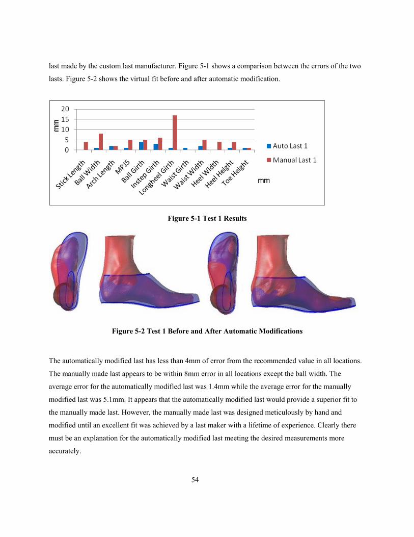
54
last made by the custom last manufacturer. Figure 5-1 shows a comparison between the errors of the two
lasts. Figure 5-2 shows the virtual fit before and after automatic modification.
Figure 5-1 Test 1 Results
Figure 5-2 Test 1 Before and After Automatic Modifications
The automatically modified last has less than 4mm of error from the recommended value in all locations.
The manually made last appears to be within 8mm error in all locations except the ball width. The
average error for the automatically modified last was 1.4mm while the average error for the manually
modified last was 5.1mm. It appears that the automatically modified last would provide a superior fit to
the manually made last. However, the manually made last was designed meticulously by hand and
modified until an excellent fit was achieved by a last maker with a lifetime of experience. Clearly there
must be an explanation for the automatically modified last meeting the desired measurements more
accurately.

55
The two primary inputs for the modification process are the allowances and the foot model. Since both
automatic modification and manual modification used the same allowances as a guideline, this cannot be
the source of the discrepancy. The foot model on the other hand, is drastically different for the two
methods. In the case of the manual modification, the actual human foot was measured directly by a skilled
professional. For the automatically modified last on the other hand, a scanner and software package was
used to obtain the model. As explained in Chapter 2, the scanner has many deficiencies and likely does
not create an accurate model of the foot.
5.2 Test 2
In an effort to provide a more accurate representation of the foot for the automatic modification, a new
method for obtaining a model of the foot was used; a plaster model was created and scanned. The
remainder of the test was carried out identical to test 1. The results are shown in Figure 5-3. Figure 5-4
shows the virtual fit before and after automatic modification.
Figure 5-3 Test 2 Results

56
Figure 5-4 Test 2 Before and After Automatic Modification
Average error for the automatically modified last was found to be 1.8mm while for the manually
modified last it was 2.8mm. Once again the automatic modification error was found to be less than the
manual modification error. Similar to test 1, this result is justified in that the model of the foot obtained
likely was inaccurate. The process of attempting to match foot measurements by washing away material
was a significant source of error. Even if the measurements were matched identically, error may have
resulted as the methods for the manual measurement and the automatic measurement could have been
different. Also, during shipping of the casting, damage occurred to the fifth ball joint area. The broken
parts were reconnected for scanning though error in the scan could have resulted. Another difficulty that
occurred was locating the instep point. When the plaster was washed to remove the ridge on the dorsal
surface, a smooth surface was obtained that provided no clues as to the exact location of the point. It may
be that the instep point was incorrectly located.
The ball girth measurement is the one measurement for the automatically modified last that has
significant error. This can be accounted for as follows. Girth modifications are done in the following
order: ball, instep, waist, long heel. Each girth modification has an effect on all of the girth measurements.
By modifying the long heel girth last, it will always be the most accurately matched. It is possible that the
ball girth was accurately matched first, but when the other three girth measurements were modified, they
had a detrimental effect on the ball girth measurement.
Once again, this test has shown that desired measurements can be accurately matched. However, to make
a fair comparison to the last manufacturers last, a more accurate scanning technique is required.

57
5.3 Test 3
Test 3 was carried out identical to test 2. Similar results were obtained eccept that the instep girth was
now the measurement for automatic modification with significant error (Figure 5-5). This is justified
similarly to how the ball girth error was justified in Test 2. Average error for the automatically modified
last was 2.2 while for the manually modified last it was 5.2. Figure 5-6 shows the virtual fit before and
after automatic modification.
Figure 5-5 Test 3 Results
Figure 5-6 Test 3 Before and After Automatic Modification

58
5.4 Tool path Planning Results
5.4.1 Offset Mesh Tool path Planning Results
A tool path was generated as described in chapter 4 (Figure 5-7). An even step over and smooth curves
resulted. The fixturing cylinder was also offset by the radius of the tool and resulted in a seamless
transition from the last to the fixturing cylinder. Computation time was less than a minute; a result of
using a curve as many steps as possible before dividing it into the actual tool path points.
Figure 5-7 Offset Mesh Tool path
5.4.2 Tool Radius Offset Tool Path Planning Results
Computation time was significantly longer for this method than the Offset Mesh Tool Path Planning. This
is primarily because each point in the contact path array had to be individually offset from the mesh.
Gouging did not occur on the body of the last because the radius of the surface was always smaller than
that of the tool. However, tool path planning at the intersection between the fixturing cylinder and last
body posed a problem. As shown in Figure 5-8, the tool will gouge the part when the offset is calculated
from the cylinder or last near the intersection. There are various ways of dealing with this; however all
add a significant amount of complication.
An interesting aspect of this method to note is the tool path step-over spacing. As shown in Figure 5-9 the
tool path will sway back and forth as the surface angle changes. This may have an impact on surface
finish and cutting forces. However, exact surface finish is not of great importance and cutting forces will

59
be relatively low (lasts for custom shoes are generally machined out of plastic or wood), therefore minor
cutting force changes are irrelevant.
Because of shorter computation times and the ability to better deal with the fixturing cylinder joint, the
Offset Mesh Tool Path Planning method is the preferred technique.
Figure 5-8 Gouge Near Fixturing Cylinder
Figure 5-9 Tool Radius Offset Tool path VS Offset Surface Tool path

60
Chapter 6 Conclusion
Mass produced footwear is inadequate for a signification percentage of people, yet they do not obtain
custom footwear due to the expense. The primary source of skilled labor for custom footwear
manufacturing is shoe last production. Improving shoe last production was the focus of this thesis.
A script was written within a commercial CAD program to automate the last production process from foot
measuring to last modification to tool path planning. The algorithms were also designed to provide
orthopedic advantages over existing programs in an attempt to minimize the possibility of requiring
rework.
Feet were divided into two subsets, the first being those that may possess irregular measurements but do
not have significant deformities. This subset could be dealt with purely with the automatic algorithms
designed. For the remainder of feet that do not fit into this subset, manual tools for modification were
provided. These tools are also useful for making stylistic changes such as adjustments to toe character.
The goal of creating a virtual fit was achieved by using available tools to adjust the foot to the intended
position inside the shoe. The last measurements were taken relative to the foot‟s critical points. The
comfort of the shoe that would result from the last could then be quantified by how closely the last
measurements matched the foot measurements while taking into account recommended allowances.
For the automatic modification, the designed algorithms were able to adjust three different lasts with a
reasonable degree of success. A custom last manufacturer manually modified three lasts in parallel.
Average last measurement error from the recommended last measurement was 1.8mm for the
automatically modified last and 4.4mm for the manually modified last. The manually made last appeared
at first to be of inadequate fit. However, it was realized that the reason for this was because the hand made
last was made for the actual foot rather than the digitized foot which likely was created with significant
error.

61
As an alternative quantification of error for the manually made last, the manufacturer provided an
estimated error of approximately 2mm. However, because of the error produced in scanning, it was
inappropriate to compare the geometric similarity between the automatically modified last and the custom
manufacturer‟s last.
By combining the automatic algorithm with the manual tools outlined, an appropriate last can be created.
Much work must still go into perfecting the algorithm and making the system user friendly. Using the
system created in this project a custom last can be designed in drastically less time than that allowed by
current technologies.
A method for creating a tool path by offsetting the drive surface was successfully implemented.

62
Chapter 7 Recommendations
The goal of automatically modifying last measurements to match recommended measurements was
achieved. Whether or not this measurement adaptation ensures that the last would closely match the
custom manufacturers last could not be determined. This was due to significant error in the methods used
for digitizing the feet. An improved digitizing method should be used and the tests should be redone. The
position of the foot during scanning should also be addressed; by positioning the foot in the correct
position prior to scanning, any error produced by manipulating the foot in 3D could be removed. This
would provide the operator with more control on foot position.
The recommended measurements consisted of the foot measurements plus recommended allowances. The
recommended allowances used were constants provided by the custom manufacturer and were
specifically for a male foot of around size 12. By limiting the feet for the 3 test to approximately size 12
male feet, the variables introduced by varying recommended allowances and graded lasts were negated.
To expand the program to work with all clients, a large variety of lasts must be scanned into the system
and a grading system must be created. More functionality must be designed to deal with a greater variety
of footwear types such as boots and high heels. The manual modification system must be further
developed to give the operator an easy to understand and simplified interface.
The method used for automating the controls in Rhinoceros 3D for this project is a plugin called
Rhinoscript. Rhinoscript has a set of its own unique commands and as well it can access all of the
standard commands in Rhinoceros 3D. To use the scripts, the code must be manually placed in buttons or
run from a file. There is no convenient way to provide the functionality to another party easily and
securely, thus minimizing its potential for commercialization.
An alternative is to write a plugin for Rhinoceros 3D. Plugins can be written in VB.net or C++. There are
many 3rd party plugins written for Rhinoceros 3D including MacNeels own rendering and animation
plugins. In fact, several specialized plugins for the footwear industry already exist. A plugin is a secure
convenient method for distributing the program commercially. Also, the access to Rhinoceros 3D‟s
functionality is at a much lower level and therefore is more robust and results in faster computations.

63
Despite these advantages, distributing a plugin commercially is still not ideal because the user is required
to own Rhinoceros 3D and its customizability is still quite limited when compared to the freedom of
building a program from scratch with C++ for example. However, the time required to develop the tools
provided by Rhinoceros 3D that were used in this project may prove impractical.

64
Appendix A
Structure of the Foot
[25]

65
[25]

66
Appendix B
Measuring the Foot
[7]
[8]

67
Appendix C
Required Modifications
Regional last modification
Fore Part of a last
Toe width
o Medial
o Lateral
o Bilateral
Toe height (depth)
o Dom shaped highest point in the center of toes (2nd
and 3rd
hammer or mallet toe)
o Higher at the big toe reduced gradually as it moves towards the later side (small toe) area
(more common or average toe depth)
Toe shape
o Pointed
o Semi Pointed
o Round
o Oblique
o Square
Toe angle
o Swing to the middle (medial)
o Swing towards the outside (lateral)
o Open like a fan (toes are spread wide both medial and lateral direction)
Localized toe modification
o Spot modification (stretching out a particular spot)
Toe spring/Length
o Clearance of the toe from the ground using the ball joint line as a pivoting point.
o Toe length from the medial ball joint to the longest toe (this could be measured from the
center of the ball joint to the longest toe)
Mid part and fore part adjacent region
Ball joint
o Over all ball joint width
o Medial ball joint width

68
o Lateral ball joint width
o Dorsal modification both medial and lateral region for bunion and bunionette.
o Dorsal modification on the entire ball joint area extending to the front region and back to the
mid region. Either stretching out (edema) or depressing it in for slim feet.
o Ball joint line angle
Mid part region
Lateral side mid foot (last)
o Lateral mid foot extension: Stretching out the lateral mid foot curvature area for
(Pes cavous, polio or post polio foot)
o Lateral mid foot depression: Depressing in the lateral mid foot curvature area (severe
pronation, tibialis posterior tendon rupture)
Medial side mid foot (last)
o Medial mid foot extension: Stretching out the medial mid foot curvature area (pronation, flat
foot, swollen joint due to arthritis.)
o Medial mid foot depression: Depressing in the medial mid foot curvature area (pes cavous
foot, polio or post polio)
o Medial mid foot bottom surface extension: Widening the medial aspect of mid foot surface
area (flat foot, pronation, follen arches, tibialis, posterior tendon rupture.
Mid foot region general
o Instep extension: Extending dorsal aspect of the instep area (high instep, edema, polio or
post polio
o Instep depression: Reducing the volume of instep. (flat foot, pronation, low instep and low
arches.
Back part region
Apart from the back curve modification of last for custom shoes are more or less extensions of
the mid region modification. The back part region is also affected by the lower leg and ankle area
dimension and shape.
o Expand (feel-up volume) lateral/medial anterior heel curvature: (swollen ankle, large lower
leg)
o Reduce (Volume) lateral/medial anterior heel curvature: (Skinny leg and ankle, slip-on shoe
design)
o Back curve: mild curvature for average type of foot, straight back for boot and swollen
lower leg, exaggerated curve for severe pronation and charcot foot.

69
Other modification required:
In order to accommodate orthotics or foot bed, the entire bottom could be dropped down from
heel to toe with a variation of regional value. At the heel, ball joint and toe or with a uniform
value.
Heel height changes using user defined pivot point
These are the simplified points to consider either with automatic modification or with human
intervention.

70
Bibliography
1. Public Health Agency of Canada. Retrieved 20 November 2008, from http://www.phac-
aspc.gc.ca/seniors-aines/pubs/info_sheets/foot_care/index.htm.
2. Rossi, William A., 1988. Futile Search for the Perfect Fit. Journal of Testing and Evaluation,
v16, n4. Marchfield, MA, U.S.A.
3. American Pediatric Medical Association. Retrieved 9 September 2008, from
http://apma.org/s_apma/index.asp.
4. Hefferman, J., 2007. Shoe Last Construction Summary. University of Waterloo, Waterloo,
Canada.
5. Bao, P., Soundar, P., Yang, T., 1994. Integrated Approach to Design and Manufacture of
Shoe Lasts for Orthopaedic use. Department of Engineering Management, Old Dominion
University, Norfolk, VA, U.S.A.
6. Houle, P., Beaulieu, E., Liu, Z., Novel Fully Integrated Footwear: From 3D Digitization to
Manufacturing. Neogenix Technologies Inc, Sainte-Foy, Canada.
7. Witana, P.C., Xiong, W.S., Zhao, J., Goonetilleke, R.S., 2006. Foot measurements from
three-dimensional scans: A comparison and evaluation of different methods. Human
Performance Laboratory, Department of Industrial Engineering and Logistics Management,
Hong Kong University of Science and Technology, Clear Water Bay, Hong Kong.
8. Zhao, J., Xiong, S., Bu, Y., Goonetilleke, R.S., 2007. Computerized girth determination for
custom footwear manufacture. Human Performance Laboratory, Department of Industrial
Engineering and Logistics Management, Hong Kong University of Science and Technology,
Clear Water Bay, Hong Kong.
9. Zhao, J., Goonetilleke R.S., 2007. Locating Anatomical Points on Foot from 3D Point Cloud
Data. Computer School, Wuhan University, Wuhan, Hubei, PR China.
10. Leng, J., Du, R., 2006. A CAD Approach for Designing Customized Shoe Last. Computer
Aided Design and Applications Vol. 3. The Chinese University of Hong Kong.
11. Shoemaster, 2007. Shoemaster Orthopedie, Shoemaster, Retrieved 10 November 2008, from
http://www.shoemaster.co.uk/products/orthopedie.html.

71
12. Ideas. FootCAD, Ideas. Retrieved 15 November 2008, from
http://www.ideas.be/default.aspx?tabid=267.
13. Precision 3D, FotoScan 3D, Precision 3D. Retrieved 10 November 2008, from
http://www.precision3D.co.uk/?gclid=CMvI3o_zwpcCFRIfDQodFkeBSQ.
14. Brannock, 2008. Instructions. Retrieved 15 November, 2008, from http://brannock.com/cgi-
bin/start.cgi/brannock/instructions.html#fitting.
15. Greater Rochester Orthopedics, 2004. Common Foot Problems. Retrieved 15 November,
2008, from http://www.gro-md.com/artman/publish/article_23.shtml.
16. Rutten, D., 2007. Rhinoscript 101 for Rhinoceros 4.0. Robert McNeel and Associates.
17. Sederberg, 1986. Free-Form Deformation of Solid Geometric Models. Computer Graphics,
vol:20 iss:4.
18. Mochimaru, M., Kouchi, M., 1234. Last Customization From an Individual Foot Form and
Design Dimensions. National Institute of Advanced Industrial Science and Technology.
Koto-ku, Tokyo, Japan.
19. Chadnov, R.V., Skvortsov, A.V. 2004. Convex Hull Algorithms Review. Korus. Tomsk,
Russia.
20. Chase, T., Cleary, J., Luo, R., Custom Shoe Last Fabrication through CNC milling. Center
for Robotics and Intelligent Machines. North Carolina State University, Raleigh, NC.
21. Chen, J., Gong, Y., Jin, T., Tong, S., 2005. Development of an Integrated CAD/CAM System
for Shoe Last. International Conference on Mechatronics & Automation. Niagra Falls,
Canada.
22. Zeid, I., 2005. Mastering CAD/CAM. McGraw-Hill Companies, Inc., 1211 Avenue of
Americas, New York, NY, U.S.A.
23. Tang, K., Cheng, C.C., Dayan, Y., 1995. Offsetting surface boundaries and 3-axis gouge-free
surface machining. Computer-Aided Design, Vol. 27, No. 12, pp. 915-927. Ann Arbor, MI.
24. Smid, J., 1942. Handbook of Shoe Designers. Bata Shoe Co., LTD. Batanagar.
Related Documents