327 Automation in construction Roozbeh Kangari Associate Professor, School of Civil Engineering, Georgia In- stitute of Technology, Atlanta GA 30332, USA and Tetsuji Yoshida Manager, Technology Division. Shimiza Corporation, Kyobashi 2-Chome, Chuo-Ku, Tokyo, Japan 16-1 Robots are being used in increasing numbers in manufac- turing throughout the world. The expanded use of industrial robots in manufacturing and the increased projections of greater numbers in the future has resulted in a greater interest by the construction industry. This paper describes five proto- type robots developed by Shimizu Corporation for applications in construction industry. Keywords: Automation, Biological shield, Concrete plastering, Construction industry, Fireproofing, Painting. | Dr. Roozbeh Kangari is an associate professor of Civil Engineering, special- ized in automation in the construction industry. He received his Ph.D. from University of Illinois at Urbana- Champain in 1982. Then, he joined the Civil Engineering School at Geo- rgia Institute of Technology. He has done extensive research in application of automation in the construction in- dustry. He is a member of the Com- puter Integrated Manufacturing Sys- tems at Georgia Tech. Mr. Tetsuji Yoshida is currently manager of engineering Department at Shimizu's Space Robotics Center. He has done extensive research in ap- plication of automation and robotics in the construction industry. During his work at Shimizu's Technology Di- vision, Mr. Yoshida initiated the idea of robotics in construction, and since then he has been the driving force behind the automation program at Shimizu. North-Holland Robotics and Autonomous Systems 6 (1990) 327-335 1 Introduction In the past decade, the problem of productivity has attracted international attention. One of the possible means of increasing productivity is auto- mation and robotization. While the application of robots in the manufacturing is now well estab- lished, the range is continually expanding into other fields such as construction. Robotics in the construction industry is a young and fast-growing interdisciplinary field, in which many researchers are challenging to create produc- tive, cost efficient, and smarter machines. Some researchers are exploring socio-economic feasibil- ity and the general principles of robotics, while others are devoting their efforts to the actual implementation of robots that work in a construc- tion field. But it is only recently that the subject has begun to emerge as a coherent but multi-disci- plinary activity. Although the construction industry so far has managed to develop highly productive systems without the help of robots, but there are specific areas of application that the industry would be- nefit from robots application. The main ones are the application of robots in construction processes which can produce better quality with faster pro- duction. Another application area is in hazardous work environment that would be dangerous for a human operator. The robots can also be used to perform construction tasks that are boring or tir- ing for the human operators [1]. The objective of this paper is to introduce prototype construction robots developed by Shimizu Corp., one of the largest construction companies in Japan. The company is actively in- volved in research and developments of practical robots in construction field. Currently research is in progress in the following areas: (1) Building construction (Fireproofing spray robot, Steel beam positioning manipulator, Radio control auto-release clamp, Ceiling panel position- ing robot, Multi-purpose traveling vehicle for con- crete slab finishing, Concrete floor finishing robot, 0921-8830/90/$03.50 © 1990 - Elsevier Science Publishers B.V. (North-Holland)

Welcome message from author
This document is posted to help you gain knowledge. Please leave a comment to let me know what you think about it! Share it to your friends and learn new things together.
Transcript
327
Automation in construction
Roozbeh Kangari Associate Professor, School of Civil Engineering, Georgia In- stitute of Technology, Atlanta GA 30332, USA
and
Tetsuji Yoshida Manager, Technology Division. Shimiza Corporation, Kyobashi 2-Chome, Chuo-Ku, Tokyo, Japan
16-1
Robots are being used in increasing numbers in manufac- turing throughout the world. The expanded use of industrial robots in manufacturing and the increased projections of greater numbers in the future has resulted in a greater interest by the construction industry. This paper describes five proto- type robots developed by Shimizu Corporation for applications in construction industry.
Keywords: Automation, Biological shield, Concrete plastering, Construction industry, Fireproofing, Painting.
|
Dr. Roozbeh Kangari is an associate professor of Civil Engineering, special- ized in automation in the construction industry. He received his Ph.D. from University of Illinois at Urbana- Champain in 1982. Then, he joined the Civil Engineering School at Geo- rgia Institute of Technology. He has done extensive research in application of automation in the construction in- dustry. He is a member of the Com- puter Integrated Manufacturing Sys- tems at Georgia Tech.
Mr. Tetsuji Yoshida is currently manager of engineering Department at Shimizu's Space Robotics Center. He has done extensive research in ap- plication of automation and robotics in the construction industry. During his work at Shimizu's Technology Di- vision, Mr. Yoshida initiated the idea of robotics in construction, and since then he has been the driving force behind the automation program at Shimizu.
North-Holland Robotics and Autonomous Systems 6 (1990) 327-335
1 Introduction
In the pas t decade, the p r o b l e m of p roduc t iv i ty has a t t rac ted in te rna t iona l a t tent ion . One of the poss ible means of increas ing p roduc t iv i ty is auto- ma t ion and robot iza t ion . Whi le the app l i ca t ion of robots in the manufac tu r ing is now well es tab- lished, the range is con t inua l ly expand ing into other fields such as const ruct ion.
Robot ics in the cons t ruc t ion indus t ry is a young and fas t -growing in te rd i sc ip l inary field, in which many researchers are chal lenging to create p roduc- tive, cost efficient, and smar te r machines . Some researchers are explor ing soc io-economic feasibil- i ty and the general pr inc ip les of robot ics , while others are devot ing their efforts to the ac tua l imp lemen ta t ion of robots that work in a const ruc- t ion field. But it is only recent ly that the subject has begun to emerge as a coherent bu t mul t i -d isc i - p l inary activity.
Al though the cons t ruc t ion indus t ry so far has managed to develop highly p roduc t ive systems wi thout the help of robots , bu t there are specific areas of app l ica t ion that the indus t ry would be- nefit f rom robots appl ica t ion . The main ones are the app l ica t ion of robots in cons t ruc t ion processes which can p roduce be t te r qual i ty with faster p ro- duct ion. A n o t h e r app l ica t ion area is in haza rdous work envi ronment that would be dangerous for a h u m a n opera tor . The robots can also be used to pe r fo rm cons t ruc t ion tasks that are bor ing or tir- ing for the h u m a n opera to r s [1].
The object ive of this p a p e r is to in t roduce p r o t o t y p e cons t ruc t ion robo t s deve loped by Shimizu Corp. , one of the largest cons t ruc t ion companies in Japan. The c o m p a n y is act ively in- volved in research and deve lopment s of prac t ica l robots in cons t ruc t ion field. Cur ren t ly research is in progress in the fol lowing areas: (1) Building construction ( F i r e p r o o f i n g sp ray robot , Steel beam pos i t ion ing man ipu la to r , R a d i o cont ro l auto-re lease c lamp, Cei l ing pane l pos i t ion- ing robot , Mul t i -pu rpose t ravel ing vehicle for con- crete slab finishing, Concre te f loor f inishing robot ,
0921-8830/90/$03.50 © 1990 - Elsevier Science Publishers B.V. (North-Holland)
328 R. Kangari. T. Yoshida /Automation in constr~tction
Exterior wall painting robot, Automatic silo lining system; (2) Cioil works (Cast in situation substructure sys- tem-giant, Shield tunnel auto drive system); (3) Nuclear plants (One piece reactor removal sys- tem, Activated concrete cutting robot); (4) Manufacturing facilities (Clean automation system robot); and (5) Space deoelopment (Construction robot in space, Lunar base construction robot). This paper will focus on: Activated concrete cut- ting robot, Concrete floor finishing robot, Ceiling panel positioning robot, Exterior wall painting robot, and Fireproofing spray robot.
Four key requirements for a successful applica- tion of robotics in construction industry are: in- crease in productivity, technological feasibility, quality improvement, and meeting the needs of the contractors or subcontractors.
2 Selecting robot
The process of selecting a construction process for robotization consists of four main stages. Stage one consists of feasibility study of construction work processes which have high potential for au- tomation. The feasibility study includes economic, technical, and need-based feasibilities. The objec- tive in this stage is to study whether a particular construction process should be robotized.
In stage two, the information gathered during stage one is converted into a form that can be used to describe the robot 's characteristics such as: type of movement and number of axes, speed and range of movement, work volume, required cumulative accuracy of the robot, gross weight, load capacity, power source, type of control units, method of teaching, safety features, size, and other special features.
Stage three consists of matching the character- istics of robot developed in previous stage against specifications provided by manufacturers and selection of those components which have the best fit. Then, the components are assembled to form the robot. Finally, in stage four, the robot is tested in laboratory and later in a construction site. The results of the test are then used to further improve the robot. The following robots have passed these four stages, and are practically implemented.
3 Activated concrete cutting robot
Many nuclear facilities are reaching a decom- missioning stage which requires the disposition of the plant. In these facilities, the reinforced con- crete of the biological shield surrounding the reac- tor core is usually irradiated due to the direct activation from the neutron flux. The cutting robot for dismantling biological shield is developed to remove the inner activated layer of the concrete
Coril
Level Adjusl
Outrigger
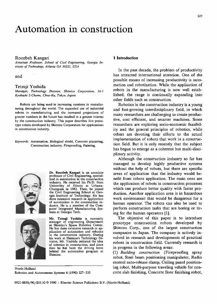
" Fig. 1. Motions of the concrete cutting robot.
Table 1 Specification of the concrete cutting robot
Coordinate type Degrees of Freedom Turning Dimensions Weight Control
Load Capacity Cut concrete Block
Dimensions (maximum)
Cylindrical 5 380 deg. H5000 mm, Dia 2250 mm 15 tons Programmable sequence
control with sensor feedback
300 kgf Ll100 ram, W400 ram,
H1000 mm
R. Kangari, T. Yoshida / Automation in construction 329
I
P o l a r c r a n e
r ; . . .z"~__..J'~._.,
/
control console I II Cable win(
B l o c k t r a n s f e r l e v i t e
i C o n t a t n e r
P o w e r
I
W a t e r
; • . ° . . - . ° . . ° - . . . ; " ' • ' . . . • . . °
I • o •
• L o °
• • ,., • °
i ̧ - ° . .
Hydraulic power unit • • - t
• e, ~upply ' ."~
• °
H.F. Inverter "."
cuf,,,~ re,pig:: I
~ .'°"o "°i,
i:i:/ _
• . . . , , . _ _ . . ~ . _ J - f ~ .
• . o . . . . . : . . . ; • . . . o . . . . ,
.:". i:. i . ,i.ii !. - i!ii
~ , . : . ;, . - . . . . . . . ~ : • .:.'. , . ~ . ' , . . . , . . . . . . •
. . . . 2:. •io- ; - o ° . . ° .
Dust collector
Waste processing equipment
L_J Stack
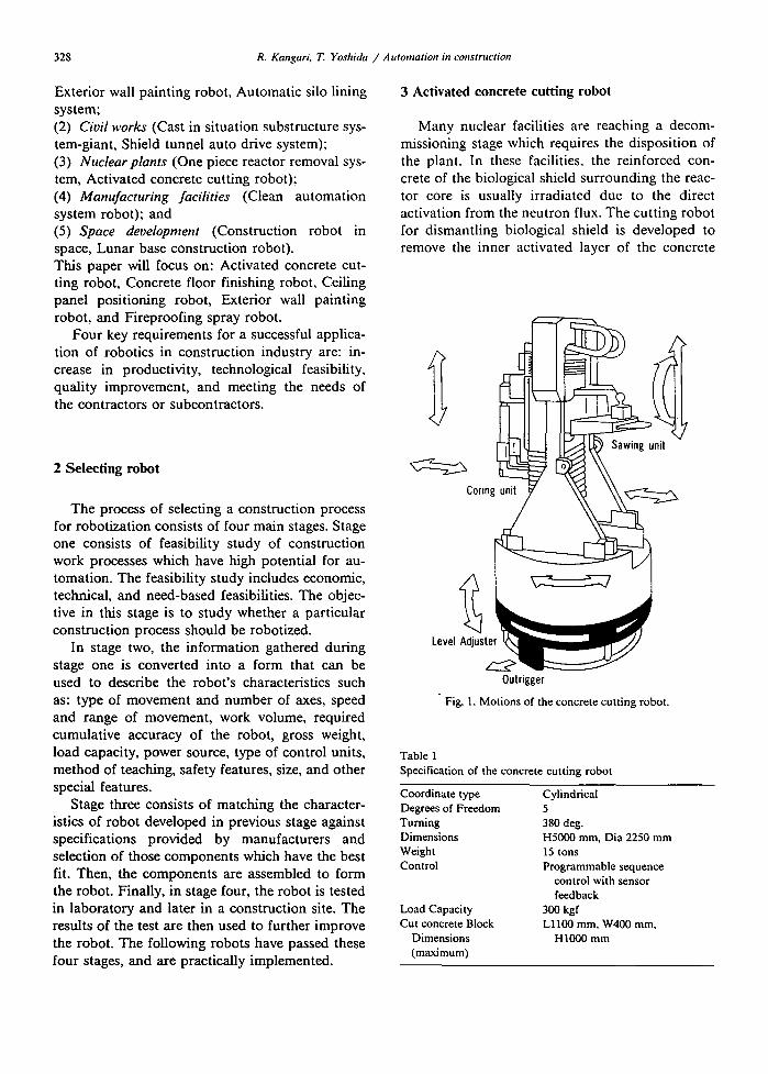
Fig. 2. Activated concrete cutting dismantling system•
Table 2 Outline of the radioactive concrete cutting test
Cutting Speed Feed Rate of Sawing at 100 mm Depth of Cut (R/C: Reinforced Concrete) Coring Rate Tool Wear Rate Minimum Quantity of Coolant
788 rpm at sawing, 436 rpm at coring 81 mm/min at 13 mm-steel lined concrete 300 mm/min at vertical cutting of R / C 200 mm/min at horizontal catting of R / C 50 mm/min at R/C 0.2 mm/m at sawing, 0.03 mm/m at coring 4 L/min for sawing, 3 L/min for coring
330 R. Kangari. T. Yoshida /Automat ion in construction
biological shield by concrete sawing and core stitch drilling.
This robot has five degrees of freedom with a cylindrical motion. Fig. 1 shows the motions of cutting robot. Total height of the robot is 500 cm and it has 15 tons weight. It uses a programmable sequence control system with sensor feedback. Ta- ble 1 lists the specification of the robot. Fig. 2 represents an integrated dismantling system which includes: cutting robot, polar crane, waste processing unit, dust collector, block transfer de- vice, control system, power supply, and water supply units. The robot moves within the shield wall cavity while suspended from a crane.
Activated concrete removal sequence by this robot consists of: (1) horizontal cutting, (2) concrete core drilling, (3) vertical concrete cutting, and (4) removal of the cut concrete blocks. To reduce tool changing time, the robot is equipped with two arms, one for a sawing ma- chine and the other for a coring machine fitted in opposite directions and actuated simultaneously.
To develop a practical robot, first a prototype robot was designed and applied in a cutting test. Measurements were taken of cutting depth, cut- ting speed, electrical power consumption, wear rate of diamonds, quality of the black and core coolant, quantities of dust and slurry produced, and reliability of the model. The test results are shown in Table 2. Based on this prototype, a robot for practical use is developed [2].
4 Concrete floor finishing robot
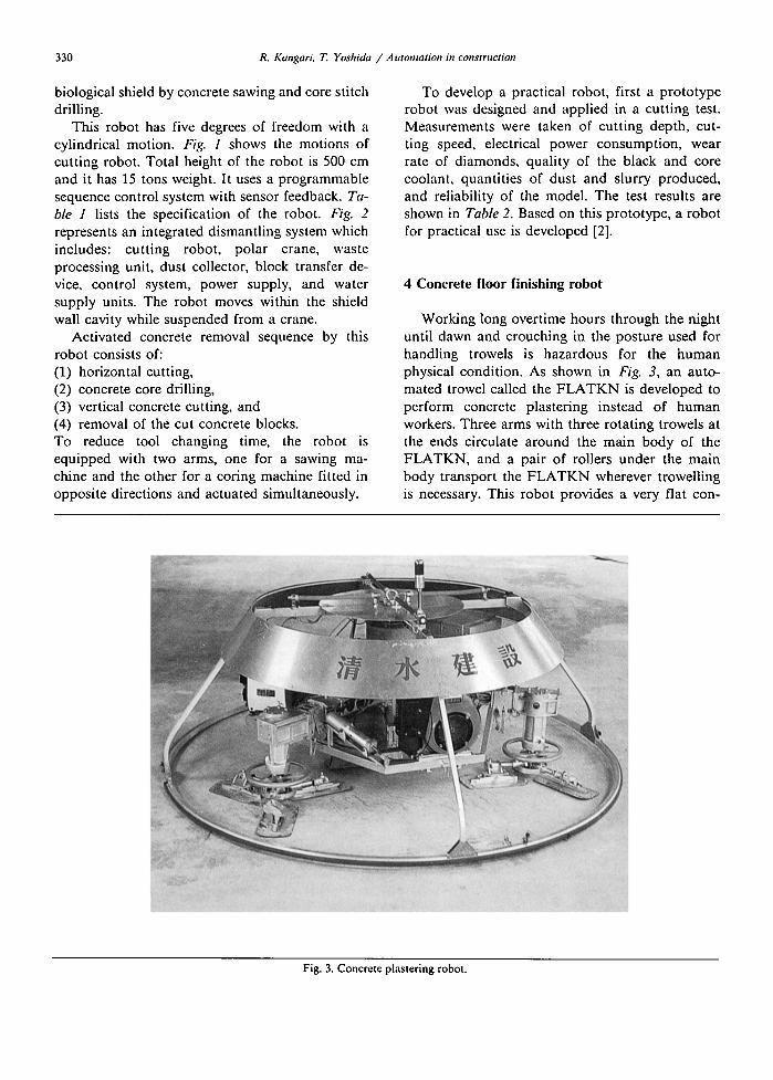
Working long overtime hours through the night until dawn and crouching in the posture used for handling trowels is hazardous for the human physical condition. As shown in Fig. 3, an auto- mated trowel called the F L A T K N is developed to perform concrete plastering instead of human workers. Three arms with three rotating trowels at the ends circulate around the main body of the FLATKN, and a pair of rollers under the main body transport the F L A T K N wherever trowelling is necessary. This robot provides a very flat con-
Fig. 3. Concrete plastering robot.
R. Kangari, T. Yoshida / Automation in construction 331
Table 3 Specifications of the plastering robot
Dimensions Maximum diameter height
Weight 300 kg Travel speed 0 to 10 m/min Trowel Blade size
Rotating speed Revolving speed Blade angle
Power source Trowel Travelling device and controller
Control By radio remote control (FM, 9 ch) - Moving back and forth - Left or right turning - Left or right correction - Trowel rotating speed control - Travel speed control
Work capacity 400 to 800 m2/h
2300 mm 810 mm
L290, W150 mm 70 to 100 rpm 0 to 13 rpm 0 to 10 deg. 5.5 PS engine 550 VA dynamo
crete finish floor. It accomplishes a better quality than a human worker.
The concrete plastering robot has 300 kg weight, 230 cm maximum diameter, and 81 cm height. Table 3 presents the specifications of the robot. F L A T K N provides a fine finishing accuracy, and requires simple preparat ions and clearing away. The robot has a high work efficiency of 400 to 800 square meters an hour. This means a work perfor- mance of about five times of a plasterer's job. The system is simple to operate and the angle of the trowel can easily be adjusted. Safety devices such as automatic stop and display lamps are imple- mented in the F L A T K N .
5 Ceiling panel positioning robot (CFR-I)
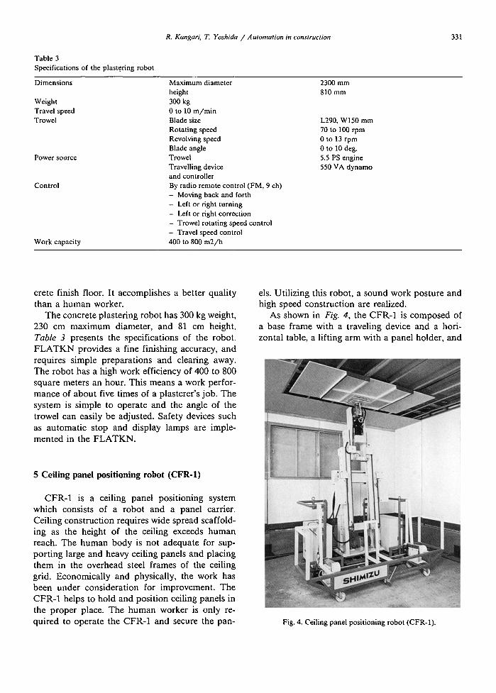
CFR-1 is a ceiling panel positioning system which consists of a robot and a panel carrier. Ceiling construct ion requires wide spread scaffold- ing as the height of the ceiling exceeds human reach. The human body is not adequate for sup- port ing large and heavy ceiling panels and placing them in the overhead steel frames of the ceiling grid. Economical ly and physically, the work has been under consideration for improvement. The CFR-1 helps to hold and position ceiling panels in the proper place. The human worker is only re- quired to operate the CFR-1 and secure the pan-
els. Utilizing this robot, a sound work posture and high speed construct ion are realized.
As shown in Fig. 4, the CFR-1 is composed of a base frame with a traveling device and a hori- zontal table, a lifting arm with a panel holder, and
Fig. 4. Ceiling panel positioning robot (CFR-1).
332 R. Kangari, T. Yoshida /Automation in construction
Table 4 Specifications of the CFR-I
Robot Dimensions L1380, W700, H1750 mm Weight 300 kg Travel Speed 3 m/min (working)
30 m/min (transporting) Manipulator Degrees of freedom 4 (X-Y table) Motion range X axis 300 mm
Y axis 150 mm Z axis 1500 mm a axis 90
Panel carrier Dimensions L1900, W500, HI000 mm Weight 50 kg Carrying capacity 20 panels
Others Power source ACI00V, 50/60 Hz Panel size L1820, W910, T12 mm
Work capacity 25 Panels/hour
a control unit. About 20 panels are loaded in the carrier, and the robot is positioned under the location where the panel will be set. Then, the panel holder is used to remove one panel from the panel carrier and lift it into position among the hanging ceiling flat bars. The robot correctly ad- justs the position of the panel using the horizontal table. Then, the robot travels to next position to set the panel. The robot has four degrees of free- dom, and work capacity of 25 panels per hour.
Table 4 provides a list of specifications for the CFR-1.
6 Exterior wall painting robot
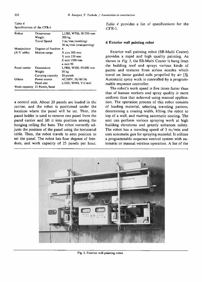
Exterior wall painting robot (SB-Multi Coater) provides a rapid and high quality painting. As shown in Fig. 5, the SB-Multi Coater is hung from the building roof and sprays various kinds of paints and textures from airless nozzles which travel on linear guided rails propelled by air [3]. Automatic spray work is controlled by a program- mable sequence controller.
The robot's work speed is five times faster than that of human workers and spray quality is more uniform than that achieved using manual applica- tion. The operation process of this robot consists of loading material, selecting traveling pattern, deternaining a coating width, lifting the robot to top of a wall, and starting automatic coating. The unit can perform various spraying work at high building elevations and greatly enhances safety. The robot has a traveling speed of 3 m / m i n and uses automatic gun for spraying material. It utilizes a programmable sequence control system with au- tomatic or manual wireless operation. A list of the
Fig. 5. Exterior wall painting robot.
R. Kangari, T. Yoshida / Automation in construction
Table 5 Specifications of the exterior wall painting robot
333
Motion range and speed
Spraying device
Control and operation control Dimensions and weight
Power source
Others
Up-down speed Coater traversing speed Gun traversing speed Gun traversing stroke Air gun rotating speed Airless gun swing angle Automatic gun for main material Automatic gun for top coating
Main material pump Paint pump Control system Operation method Dimensions Weight Electric power source Pneumatic power source Safety device Splash-prevention device Fixing device
5 m/min 3 m/min 6-80 cm/sec max 3.3m max 200 rpm + 35 deg. Automatic air gun Automatic airless gun Snake pump Diaphragm type airless pump
Sequence control and numerical Automatic or manual wireless operation 4200(W), 2465(H), 800(D) ram 1,050 kg AC200V, 30A Air-compressor (Sps) Slant sensor, limit switch Mist cover and dust Collecting fan Vacuum pad and ejector pump
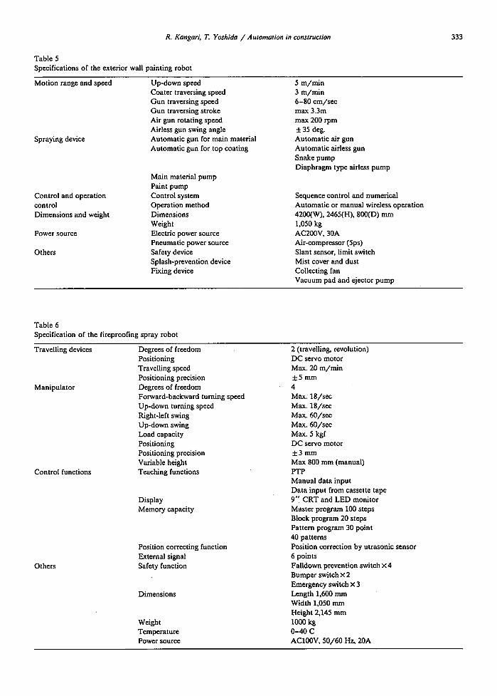
Table 6 Specification of the fireproofing spray robot
Travelling devices
Manipulator
Control functions
Others
Degrees of freedom Positioning Travelling speed Positioning precision Degrees of freedom Forward-backward turning speed Up-down turning speed Right-left swing Up-down swing Load capacity Positioning Positioning precision Variable height Teaching functions
Display Memory capacity
Position correcting function External signal Safety function
Dimensions
Weight Temperature Power source
2 (travelling, revolution) DC servo motor Max. 20 m/min +5 mm 4 Max. 18/see Max. 18/see Max. 60/see Max. 60/see Max. 5 kgf DC servo motor + 3 r a m Max 800 mm (manual) PTP Manual data input Data input from cassette tape 9'I CRT and LED monitor Master program 100 steps Block program 20 steps Pattern program 30 point 40 patterns Position correction by utrasonic sensor 6 points Falldown prevention switch × 4 Bumper switch × 2 Emergency switch x 3 Length 1,600 mm Width 1,050 mm Height 2,145 mm 1000 kg 0-40 C ACI00V, 50/60 Hz, 20A
334 R. Kangari, T. Yoshida / Automation in construction
SB-Multi Coater specifications is shown in Table 5.
7 Fireproofing spray robot
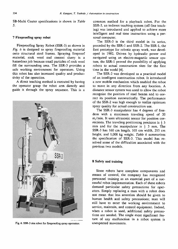
Fireproofing Spray Robot (SSR-3) as shown in Fig. 6 is designed to spray fireproofing material onto structural steel frames. Spraying fireproof material, rock wool and cement slurry is a hazardous job because small particles of rock wool fill the surrounding area. The SSR-3 provides a safe working environment for operators. Using this robot has also increased quality and produc- tivity of the operation.
A direct teaching method is executed by having the operator grasp the robot arm directly and guide it through the spray sequence. This is a
common method for a playback robot. For the SSR-3, an indirect teaching system (off-line teach- ing) was introduced and applied to achieve more intelligent and real time instruction using a per- sonal computer.
The SSR-3 is the third model in its series, preceded by the SSR-1 and SSR-2. The SSR-1, the first prototype for robotic spray work, was devel- oped in 1982. Driven by hydraulic power and navigated using an electro-magnetic sensor sys- tem, the SSR-1 proved the possibility of applying robots to actual construction sites for the first time in the world [4].
The SSR-2 was developed as a practical model of an intelligent construction robot. It introduced a new mobile mechanism which enabled the robot to move in any direction from any location. A distance sensor system was used to allow the robot recognize the position of steel beams and to cor- rect its position automatically. The performance of the SSR-2 was high enough to realize opt imum spray quality for actual construction use.
The SSR-3 manipulator has 4 degrees of free- dom with a maximum traveling speed of 20 m/min . It uses ultrasonic sensor for position cor- rections. The traveling positioning precision is ½ 5 mm and for the manipulator is ½ 3 mm. The SSR-3 has 160 cm length, 105 cm width, 215 cm height, and 1,000 kg weight. Table 6 summarizes the specification of SSR-3. This model has re- solved some of the difficulties associated with the previous two models.
Fig. 6. SSR-3 site robot for fireproofing spray operation.
8 Safety and training
Since robots have complete components and means of control, the company has recognized personnel training as an essential part of a suc- cessful robot implementation. Each of these robots demand particular safety precautions for oper- ators. Simply replacing a man with a robot does not mean that less attention should be given to human health and safety precautions; man will still have to enter the working environment to service, maintain, and control equipment. Indeed, when a robot is used, additional safety precau- tions are needed. The single most significant fea- ture of any malfunction in a robot system is unexpected movements.
R. Kangari, T. Yoshida / Automation in construction 335
Using a robot, workers tend to be less exposed to the danger of work processes than in manual systems. But nonetheless a human interface is nearly always required even in a fully automated system. Considering the safety of workers, the company has implemented the following general policies: (1) people are prevented from walking into the general work area during operation, (2) most robots have manual emergency stop but- tons which are placed within easy reach of the operator, and (3) adequate precautions are taken in the event of a fire.
9 Summary
The objective of this paper was to introduce various robots developed by the Shimizu Corp. for construction operations. The goal is to build robots which are more flexible, adjustable, and able to cope with constantly changing construction en- vironments. Research and development in con- struction robots is intended to extend present ca- pabilities of conventional equipment to an in- tegrated and fully automated system. An ancillary benefit of this type of research is an understand- ing of the key problems that need to be solved in construction engineering.
Robotics is a new and changing discipline. Basic research in many areas is still underway as the understanding of how machines may be used for complex construction tasks increases. There is a growing body of theoretical work pertaining to robots that can be put to use in real construction environments. Although there is a continuing need for a theoretical investigation of some of the dif- ficult problems in robotic perception, it is also time for experimenting and implementing these techniques in real and unstructured environments.
As with any technology, new solutions bring new problems. One of the most serious problems currently facing automation in the construction industry is the integration of information. This integration must occur in a cost effective and productive manner without loss of current con-
struction functionality. These robots represent the integration of many different ideas and technolo- gies into a working system. The challenge of build- ing construction robots is a challenge of integrat- ing not only robot components, but also of in- tegrating construction experiences, ideas, and technology.
This research work is an attempt to bridge the gap between full automation and conventional systems in the construction industry. Robots can- not yet possess the deep reasoning shown by hu- mans. This reasoning is extremely difficult, espe- cially if many sensors and complex models are involved. Further research is in progress for devel- oping construction robots with an improvement in precision, speed, and learning capacity over the kind of robots described.
Acknowledgements
The authors would like to acknowledge the contributions of Junlchiro Maeda, Tadahi Okano, Yasuo Kajioka, Seishi Suzuki, Tetsuo Hasegawa, and Takatoshi Ueno. The authors would like also to thank the U.S. National Science Foundation, Science and Technology Agency in Japan, Japan Atomic Energy Research Institute, Kobe Steel, Ltd., Star Net Structures, Inc., and Shimizu Cor- poration for providing all the necessary and val- uable information.
References
[1] R. Kangari, R. and D.W. Halpin, Automation and robotics iuconstruction: a feasibility study, Proc. 5th lnternat. Syrup. Robotics in Construction, Tokyo, Japan (June 1988) 161- 167.
[2] H. Nakamura, T. Kanao, M. Ichikawa, S. Suzuki and T. Hasegawa, Cutting robot for activated concrete wall, Proc. 9th Internat. Conf. Structural Mechanics in Reactor Technol- ogy (SMIRT), Switzerland (August 1987).
[3] T. Ueno, Y. Kajioka, H. Sato, T. Yoshida and R. Tsutsui, Research and development on robotic systems for assembly and finishing work, Proc. 3th lnternat. Syrup. Robotics in Construction, Tokyo, Japan, (June 1988) 279-288.
[4] Tetsuji Yoshida and Takatosh Ueno, Development of a spray robot for fireproof treatment, Shimizu Technical Research Report No. 4, Tokyo, Japan, March 1985.
Related Documents