Automating double ring infiltrometer with an Arduino microcontroller M. Fatehnia a, ⁎, S. Paran b , S. Kish c , K. Tawfiq a a Department of Civil and Environmental Engineering, FAMU-FSU College of Engineering, 2525 Pottsdamer Street, Tallahassee, FL 32310, USA b Department of Electrical & Computer Engineering, FAMU-FSU College of Engineering, 2525 Pottsdamer Street, Tallahassee, FL 32310, USA c Department of Earth, Ocean and Atmospheric Science, Florida State University, 1017 Academic Way, Tallahassee, FL 32306, USA abstract article info Article history: Received 12 March 2015 Received in revised form 10 August 2015 Accepted 13 August 2015 Available online xxxx Keywords: Double ring infiltrometer Arduino microcontroller eTape™ MOSFET switch Hall effect sensor Peristaltic pump In this paper, we describe the designed and tested system of automated double ring infiltrometer (DRI) that we have developed using an Arduino microcontroller, a Hall effect sensor, a peristaltic pump, a water level sensor, and a constant-level float valve. The system can be used for infiltration measurements in both single ring falling head and double ring constant head methods. The precise measurements of the current method compared to previous designed systems are not affected by sunlight, and due to the method of flow measurement, remain ac- curate even for low infiltration values. The set-up has an easy real-time data storage on a micro-SD card without a need of a portable computer in the field. It only requires a single reservoir for both inner and outer rings to which, water can be added anytime needed without affecting the measurements. The system automatically detects when the steady state infiltration rate is reached and concludes the testing and stops measurements. The system is mounted in a portable and weather resistant box and is applied to run DRI testing in the field to check the ap- plicability and accuracy of the portable set-up in field measurements. Manual testing was also performed in the field for comparison with the automated system measurements. Overall system architecture, and the design of hardware and software components are presented in details. The system configuration is illustrated for better understanding of the set-up. Published by Elsevier B.V. 1. Introduction Double ring infiltrometers are among the common test methods for in-situ measurement of the soil infiltration rate. DRI test described by ASTM D3385 consists of open inner and outer cylinders that should be manually inserted into the ground and be partially filled with a constant head of water. The infiltration rate is calculated by measuring the volume of liquid added to the inner ring to keep the liquid level constant (ASTM, 2009). The size dependency of saturated hydraulic conductivity measurements in porous media has been studied by several researchers and there have been several proposed dimensions as the minimum required diameter of test cylinders. Swartzendruber and Olsen (1961) reported that the setup with 60 and 50 cm for the outer and inner ring radius respectively was the most satisfactory throughout all the various conditions studied in a sandy soil. Ahuja (1976) reported that when an outer ring of 90 cm diameter was employed for an inner ring of 30 cm diameter, the lateral flow was practically eliminated. Bouwer (1986) suggested that a diameter of at least 100 cm should be used for accurate saturated hydraulic conductivity measurements. Youngs (1987) concluded that the results were consistent from site to site when the ring size was at least 15 cm. Gregory et al. (2005) concluded that the test employing a constant head with a double-ring infiltrometer of 15 cm inner and 30 cm outer diameters would be suitable for sandy soils generally found in North and Central Florida. Lai et al. (2010) conducted a total of 7224 numerical simulations, which resulted in a conclusion that inner ring diameters greater than 80 cm are needed to obtain reliable in situ measurement of saturated hydraulic con- ductivity. Fatehnia and Tawfiq (2014) by simulating 864 Double Ring Infiltrometer tests and applying M5′ model tree algorithm offered an equation for hydraulic conductivity estimation from the steady infil- tration rate measurements that can be used for any ring size. They also considered the effects of head of ponding, depth of the rings in the soil, initial effective saturation of the soil, and soil type on steady infiltration rate. Depending on the soil texture and the initial soil water condition, the necessary measurement time of the test may be undesirably long. In order to reduce the time consuming and tedious procedure of the mea- surement, continuous efforts have been previously done to automate the test process. One of the earliest works was done by Constantz and Murphy (1987). They utilized a single pressure transducer to develop an automated Mariotte reservoir that enabled automatic recording of water flow for constant head DRI test. Their infiltrometer was far from being automated as their method required manual water level control in both inner and outer rings. Their set-up was later modified by Ankeny et al. (1988) for use as a “tension infiltrometer.” Tension Geoderma 262 (2016) 133–139 ⁎ Corresponding author. E-mail addresses: [email protected] (M. Fatehnia), [email protected] (S. Paran), [email protected] (S. Kish), tawfi[email protected] (K. Tawfiq). http://dx.doi.org/10.1016/j.geoderma.2015.08.022 0016-7061/Published by Elsevier B.V. Contents lists available at ScienceDirect Geoderma journal homepage: www.elsevier.com/locate/geoderma

Welcome message from author
This document is posted to help you gain knowledge. Please leave a comment to let me know what you think about it! Share it to your friends and learn new things together.
Transcript

Geoderma 262 (2016) 133–139
Contents lists available at ScienceDirect
Geoderma
j ourna l homepage: www.e lsev ie r .com/ locate /geoderma
Automating double ring infiltrometer with an Arduino microcontroller
M. Fatehnia a,⁎, S. Paran b, S. Kish c, K. Tawfiq a
a Department of Civil and Environmental Engineering, FAMU-FSU College of Engineering, 2525 Pottsdamer Street, Tallahassee, FL 32310, USAb Department of Electrical & Computer Engineering, FAMU-FSU College of Engineering, 2525 Pottsdamer Street, Tallahassee, FL 32310, USAc Department of Earth, Ocean and Atmospheric Science, Florida State University, 1017 Academic Way, Tallahassee, FL 32306, USA
⁎ Corresponding author.E-mail addresses: [email protected] (M. Fatehnia), p
[email protected] (S. Kish), [email protected] (K. Tawfiq
http://dx.doi.org/10.1016/j.geoderma.2015.08.0220016-7061/Published by Elsevier B.V.
a b s t r a c t
a r t i c l e i n f oArticle history:Received 12 March 2015Received in revised form 10 August 2015Accepted 13 August 2015Available online xxxx
Keywords:Double ring infiltrometerArduino microcontrollereTape™MOSFET switchHall effect sensorPeristaltic pump
In this paper, we describe the designed and tested system of automated double ring infiltrometer (DRI) that wehave developed using an Arduino microcontroller, a Hall effect sensor, a peristaltic pump, a water level sensor,and a constant-level float valve. The system can be used for infiltration measurements in both single ring fallinghead and double ring constant head methods. The precise measurements of the current method compared toprevious designed systems are not affected by sunlight, and due to themethod of flowmeasurement, remain ac-curate even for low infiltration values. The set-up has an easy real-timedata storage on amicro-SD cardwithout aneed of a portable computer in the field. It only requires a single reservoir for both inner and outer rings towhich,water can be added anytime needed without affecting the measurements. The system automatically detectswhen the steady state infiltration rate is reached and concludes the testing and stopsmeasurements. The systemis mounted in a portable and weather resistant box and is applied to run DRI testing in the field to check the ap-plicability and accuracy of the portable set-up in field measurements. Manual testing was also performed in thefield for comparison with the automated system measurements. Overall system architecture, and the design ofhardware and software components are presented in details. The system configuration is illustrated for betterunderstanding of the set-up.
Published by Elsevier B.V.
1. Introduction
Double ring infiltrometers are among the common test methods forin-situ measurement of the soil infiltration rate. DRI test described byASTM D3385 consists of open inner and outer cylinders that should bemanually inserted into the ground and be partially filledwith a constanthead of water. The infiltration rate is calculated by measuring thevolume of liquid added to the inner ring to keep the liquid level constant(ASTM, 2009). The size dependency of saturated hydraulic conductivitymeasurements in porousmedia has been studied by several researchersand there have been several proposed dimensions as the minimumrequired diameter of test cylinders. Swartzendruber and Olsen (1961)reported that the setup with 60 and 50 cm for the outer and innerring radius respectively was the most satisfactory throughout all thevarious conditions studied in a sandy soil. Ahuja (1976) reported thatwhen an outer ring of 90 cm diameter was employed for an inner ringof 30 cm diameter, the lateral flow was practically eliminated. Bouwer(1986) suggested that a diameter of at least 100 cm should be usedfor accurate saturated hydraulic conductivity measurements. Youngs(1987) concluded that the results were consistent from site to site
[email protected] (S. Paran),).
when the ring size was at least 15 cm. Gregory et al. (2005) concludedthat the test employing a constant headwith a double-ring infiltrometerof 15 cm inner and 30 cm outer diameters would be suitable for sandysoils generally found in North and Central Florida. Lai et al. (2010)conducted a total of 7224 numerical simulations, which resulted ina conclusion that inner ring diameters greater than 80 cm are neededto obtain reliable in situ measurement of saturated hydraulic con-ductivity. Fatehnia and Tawfiq (2014) by simulating 864 DoubleRing Infiltrometer tests and applying M5′model tree algorithm offeredan equation for hydraulic conductivity estimation from the steady infil-tration rate measurements that can be used for any ring size. They alsoconsidered the effects of head of ponding, depth of the rings in the soil,initial effective saturation of the soil, and soil type on steady infiltrationrate.
Depending on the soil texture and the initial soilwater condition, thenecessary measurement time of the test may be undesirably long. Inorder to reduce the time consuming and tedious procedure of the mea-surement, continuous efforts have been previously done to automatethe test process. One of the earliest works was done by Constantz andMurphy (1987). They utilized a single pressure transducer to developan automated Mariotte reservoir that enabled automatic recording ofwater flow for constant head DRI test. Their infiltrometer was far frombeing automated as their method required manual water level controlin both inner and outer rings. Their set-up was later modified byAnkeny et al. (1988) for use as a “tension infiltrometer.” Tension
134 M. Fatehnia et al. / Geoderma 262 (2016) 133–139
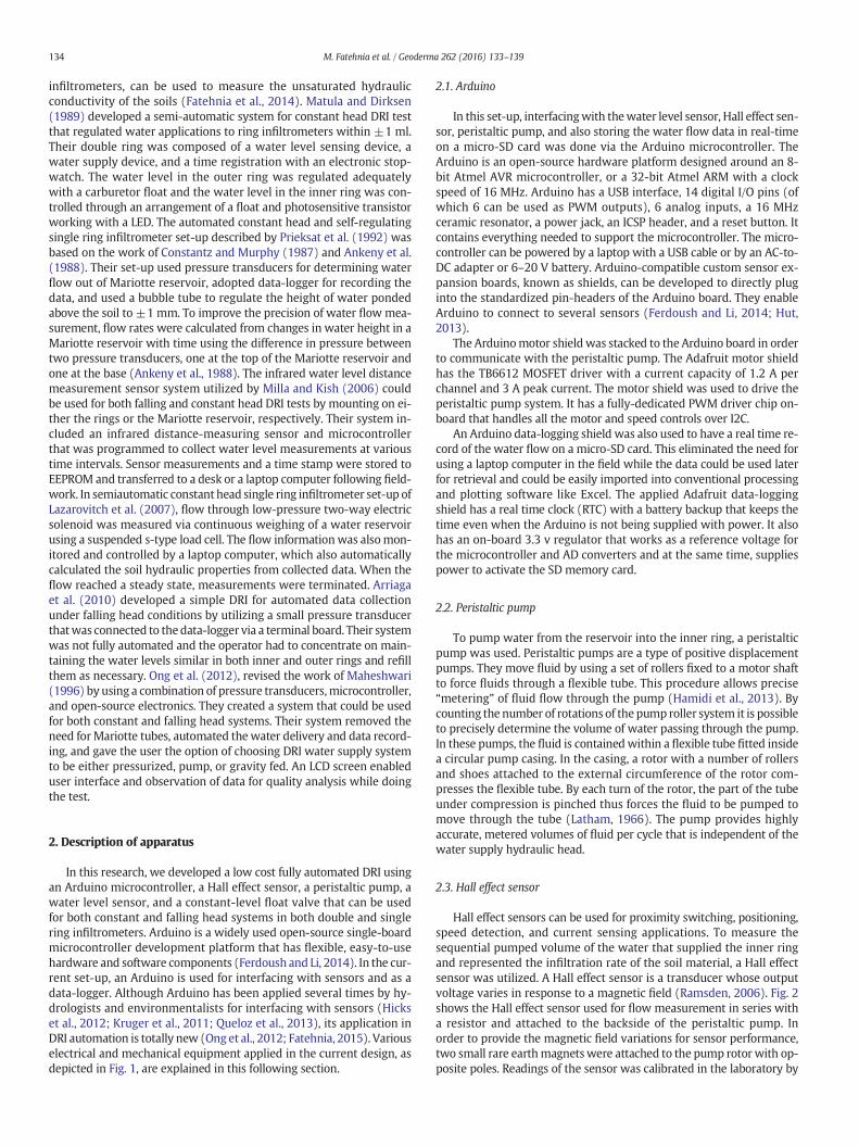
infiltrometers, can be used to measure the unsaturated hydraulicconductivity of the soils (Fatehnia et al., 2014). Matula and Dirksen(1989) developed a semi-automatic system for constant head DRI testthat regulated water applications to ring infiltrometers within ±1 ml.Their double ring was composed of a water level sensing device, awater supply device, and a time registration with an electronic stop-watch. The water level in the outer ring was regulated adequatelywith a carburetor float and the water level in the inner ring was con-trolled through an arrangement of a float and photosensitive transistorworking with a LED. The automated constant head and self-regulatingsingle ring infiltrometer set-up described by Prieksat et al. (1992) wasbased on the work of Constantz and Murphy (1987) and Ankeny et al.(1988). Their set-up used pressure transducers for determining waterflow out of Mariotte reservoir, adopted data-logger for recording thedata, and used a bubble tube to regulate the height of water pondedabove the soil to ±1 mm. To improve the precision of water flowmea-surement, flow rates were calculated from changes in water height in aMariotte reservoir with time using the difference in pressure betweentwo pressure transducers, one at the top of the Mariotte reservoir andone at the base (Ankeny et al., 1988). The infrared water level distancemeasurement sensor system utilized by Milla and Kish (2006) couldbe used for both falling and constant head DRI tests by mounting on ei-ther the rings or the Mariotte reservoir, respectively. Their system in-cluded an infrared distance-measuring sensor and microcontrollerthat was programmed to collect water level measurements at varioustime intervals. Sensor measurements and a time stamp were stored toEEPROM and transferred to a desk or a laptop computer following field-work. In semiautomatic constant head single ring infiltrometer set-up ofLazarovitch et al. (2007), flow through low-pressure two-way electricsolenoid was measured via continuous weighing of a water reservoirusing a suspended s-type load cell. The flow informationwas alsomon-itored and controlled by a laptop computer, which also automaticallycalculated the soil hydraulic properties from collected data. When theflow reached a steady state, measurements were terminated. Arriagaet al. (2010) developed a simple DRI for automated data collectionunder falling head conditions by utilizing a small pressure transducerthatwas connected to thedata-logger via a terminal board. Their systemwas not fully automated and the operator had to concentrate on main-taining the water levels similar in both inner and outer rings and refillthem as necessary. Ong et al. (2012), revised the work of Maheshwari(1996) by using a combination of pressure transducers,microcontroller,and open-source electronics. They created a system that could be usedfor both constant and falling head systems. Their system removed theneed forMariotte tubes, automated the water delivery and data record-ing, and gave the user the option of choosing DRI water supply systemto be either pressurized, pump, or gravity fed. An LCD screen enableduser interface and observation of data for quality analysis while doingthe test.
2. Description of apparatus
In this research, we developed a low cost fully automated DRI usingan Arduino microcontroller, a Hall effect sensor, a peristaltic pump, awater level sensor, and a constant-level float valve that can be usedfor both constant and falling head systems in both double and singlering infiltrometers. Arduino is a widely used open-source single-boardmicrocontroller development platform that has flexible, easy-to-usehardware and software components (Ferdoush and Li, 2014). In the cur-rent set-up, an Arduino is used for interfacing with sensors and as adata-logger. Although Arduino has been applied several times by hy-drologists and environmentalists for interfacing with sensors (Hickset al., 2012; Kruger et al., 2011; Queloz et al., 2013), its application inDRI automation is totally new (Ong et al., 2012; Fatehnia, 2015). Variouselectrical and mechanical equipment applied in the current design, asdepicted in Fig. 1, are explained in this following section.
2.1. Arduino
In this set-up, interfacingwith thewater level sensor, Hall effect sen-sor, peristaltic pump, and also storing the water flow data in real-timeon a micro-SD card was done via the Arduino microcontroller. TheArduino is an open-source hardware platform designed around an 8-bit Atmel AVR microcontroller, or a 32-bit Atmel ARM with a clockspeed of 16 MHz. Arduino has a USB interface, 14 digital I/O pins (ofwhich 6 can be used as PWM outputs), 6 analog inputs, a 16 MHzceramic resonator, a power jack, an ICSP header, and a reset button. Itcontains everything needed to support the microcontroller. The micro-controller can be powered by a laptop with a USB cable or by an AC-to-DC adapter or 6–20 V battery. Arduino-compatible custom sensor ex-pansion boards, known as shields, can be developed to directly pluginto the standardized pin-headers of the Arduino board. They enableArduino to connect to several sensors (Ferdoush and Li, 2014; Hut,2013).
The Arduinomotor shield was stacked to the Arduino board in orderto communicate with the peristaltic pump. The Adafruit motor shieldhas the TB6612 MOSFET driver with a current capacity of 1.2 A perchannel and 3 A peak current. The motor shield was used to drive theperistaltic pump system. It has a fully-dedicated PWM driver chip on-board that handles all the motor and speed controls over I2C.
An Arduino data-logging shield was also used to have a real time re-cord of the water flow on a micro-SD card. This eliminated the need forusing a laptop computer in the field while the data could be used laterfor retrieval and could be easily imported into conventional processingand plotting software like Excel. The applied Adafruit data-loggingshield has a real time clock (RTC) with a battery backup that keeps thetime even when the Arduino is not being supplied with power. It alsohas an on-board 3.3 v regulator that works as a reference voltage forthe microcontroller and AD converters and at the same time, suppliespower to activate the SD memory card.
2.2. Peristaltic pump
To pump water from the reservoir into the inner ring, a peristalticpump was used. Peristaltic pumps are a type of positive displacementpumps. They move fluid by using a set of rollers fixed to a motor shaftto force fluids through a flexible tube. This procedure allows precise“metering” of fluid flow through the pump (Hamidi et al., 2013). Bycounting the number of rotations of the pump roller system it is possibleto precisely determine the volume of water passing through the pump.In these pumps, the fluid is containedwithin a flexible tube fitted insidea circular pump casing. In the casing, a rotor with a number of rollersand shoes attached to the external circumference of the rotor com-presses the flexible tube. By each turn of the rotor, the part of the tubeunder compression is pinched thus forces the fluid to be pumped tomove through the tube (Latham, 1966). The pump provides highlyaccurate, metered volumes of fluid per cycle that is independent of thewater supply hydraulic head.
2.3. Hall effect sensor
Hall effect sensors can be used for proximity switching, positioning,speed detection, and current sensing applications. To measure thesequential pumped volume of the water that supplied the inner ringand represented the infiltration rate of the soil material, a Hall effectsensor was utilized. A Hall effect sensor is a transducer whose outputvoltage varies in response to a magnetic field (Ramsden, 2006). Fig. 2shows the Hall effect sensor used for flow measurement in series witha resistor and attached to the backside of the peristaltic pump. Inorder to provide the magnetic field variations for sensor performance,two small rare earthmagnetswere attached to the pump rotor with op-posite poles. Readings of the sensor was calibrated in the laboratory by

Fig. 1. Automated system electronics.
135M. Fatehnia et al. / Geoderma 262 (2016) 133–139
measuring the corresponding volume of the water for each rotation ofthe pump rotor.
2.4. Water level detector
Water level detector was placed in the inner ring to detect the dropof water below a reference level resulting from the infiltration of water
Fig. 2. Hall effect sensor attached to the peristaltic pump.
into the soil. Two different methods were employed for detecting thewater level of the inner ring. Thefirstmethodwas to use aMOSFET tran-sistorwater level sensor as a switch to detectwhen to turn the pump onand off. The alternative method was to use eTape™ continuous waterlevel sensor (MILONE Technologies).
The MOSFET transistor water level sensor sent a high voltage to theArduino whenever the end electrodes shown in Fig. 3a were in contactwith the water. Voltage sending was a low signal whenever the elec-trodes lost the conductivity of the water due to the water level drop.
The eTape™ sensor shown in Fig. 3b was a solid state, continuous(multi-level) fluid level detector that could be applied for level mea-surement of water or any other non-corrosive water based liquids.Compression of the sensor's envelope due to hydrostatic pressure ofthe fluid caused a resistance change proportional to the distance fromthe top of the sensor to the fluid surface which let the sensor to providea resistive output inversely proportional to the liquid level.
2.5. Constant level float valve
The water level in the outer ring, as shown in Fig. 3, was controlledmechanically by using a constant level float valve. Since, during theexperiment, there was no need to measure flow of water into the outerring, the water needed for the outer ring could be supplied using thesame elevated water container as the inner ring.
3. System construction and calibration
The designed automated DRI set-up had a 20 cmdiameter inner ringand a 40 cm diameter outer ring with 50 cm heights. An elevated watercontainer supplied the required water for both rings. Since the outerringwaterwas gravitationally supplied using a float valve, the containerneeded to be elevated. In the case of using the automated system to runsingle ring infiltrometer, the peristaltic pump would function evenwhen the water in the container was below the pump level. A constantlevel float valve was placed at the height of 15 cm above the soil surfacewithin the outer ring. This was used to keep the outer ring water levelconstant throughout the test. The water level sensor placed in the

Fig. 3. (a) Water level electrodes for MOSFET transistor & (b) eTape sensor placed in the inner ring.
Table 1Electronic components used in the design of the automated system.
Required equipment Specifications Quantity
Arduino Uno Microcontroller • 5 V operating voltage• 7–12 V recommended input voltage• 40 mA DC current per I/O pin
1
Adafruit motor shield • Max 25 V DC• 0.6 A per bridge (1.2 A peak)
1
Adafruit data-logging shield • Compatible with FAT16 or FAT32formatted cards
• Onboard real time clock (RTC)
1
eTape™ continuous fluidlevel sensor
• 12 in. length 1
MOSFET transistor circuit • 1 KΩ parallel & 1 MΩ series resistors 1Carbon film resistors • 6800 Ω 1Metal film resistors • 220 Ω 1RadioShack RS 276–150Perfboard
• 2.88 by 1.88 in. 1
RF-100 peristaltic pump • 1000 ml/min flow capacity 1 or 2a
SP12-5 Sigmas Tek sealedlead–acid battery
• 12 V• 1.5 A
2 or 3a
US1881 Hall effect sensor • 3.5 V to 24 V DC operation voltage• 50 mA maximum sinking outputcurrent
1 or 2a
Rare earth disk magnets • 0.125″ diameter• 0.03125″ ± 0.005″ thickness• 0.954 lbs optimal pull
2 or 4a
a Quantities needed if 2 pumps are used when higher water flow is needed.
136 M. Fatehnia et al. / Geoderma 262 (2016) 133–139
inner ring was connected to the Arduino Uno. In the case of continuouswater level sensor, whenever the inner ring's water level droppedbelow 9 cm, via Arduino message, the peristaltic pump that suppliedwater to the inner ring turned on. The pump continued working untilthe water level reached to 10 cm height. In the MOSFET switch, thepump continued working until the water level electrodes were in con-tact with the water.
The applied RF-100 peristaltic pump had a maximum flow rate of1000 ml/min and worked with primary power source of 12 V or 24 Vbrushless DC motor. Since the applied inner ring diameter was 20 cm,the system could be used to run an automated DRI test in soils withmaximum infiltration rate values up to 0.05 cm/s. In the case of runningthe test in granular material with higher infiltration rate values, twoperistaltic pumps should be used. Themaximumflow rate of the systemcan be increased to 2000ml/min byusing two similar pumpsworking inparallel. This can be easily done since the Arduino motor shield can runup to 4 DC motors simultaneously with maximum total power voltageof 24 V. The only changes needed to make while applying two pumpswere to replace the motor shield battery with the one that supportedthe required new voltage and current values. An Arduino code alsoneeded to be updated to handle all connected pumps. Since the threetest fields used for analyzing the set-up performance in the currentresearch had maximum infiltration values lower than 0.05 cm/s, theautomated set-upwith only one peristaltic pumpwas tested in the field.
Communicating of theArduinowith thepumpwas donevia Adafruitmotor shield that was stacked to the Arduino Uno. Two 12 V, 5 AH,rechargeable sealed lead acid batteries supplied the power needed forArduino and the motor shield. The power required for the pump andwater level sensor was supplied via the motor shield and Arduino,respectively. More batteries were needed to run the test with 2 pumps.Quantities of the electronic components needed to build the automatedsystem are itemized in Table 1. The diagram in Fig. 4 illustrates the con-nection arrangement of the pump, sensors, Arduino, and the batteries.
In the continuous water level system, a 30 cm eTape™ sensor with athickness of 0.381 mm and width of 25.4 mm was placed in the innerring. The sensor had an output range of 400–2000 Ω and resistancegradient of 60Ω/cm. The sensor resolutionwas 0.25mmwhich resultedan accurate reading ofwater level changes. However, the readings of the
sensor can be affected by temperature changes. A simple voltage dividerwith a 6800 Ω reference resistor seated on a prototyping breadboardwas used to convert the output of the sensor into voltage, see Fig. 5.
Compared to the eTape™ sensor, the MOSFET transistor sensor per-formance is not prone to drift due to temperature. For this reason, itcould provide a more accurate measurement of a specific water leveland since it was built by the authors, it had a cheaper final price. Onthe other hand, unlike the eTape™ continuous water level sensor, itcould be only applied to run constant headDRI since it could only detectwhether the electrode was in contact with water or not. The circuitapplied to run the second system is depicted in Fig. 6.
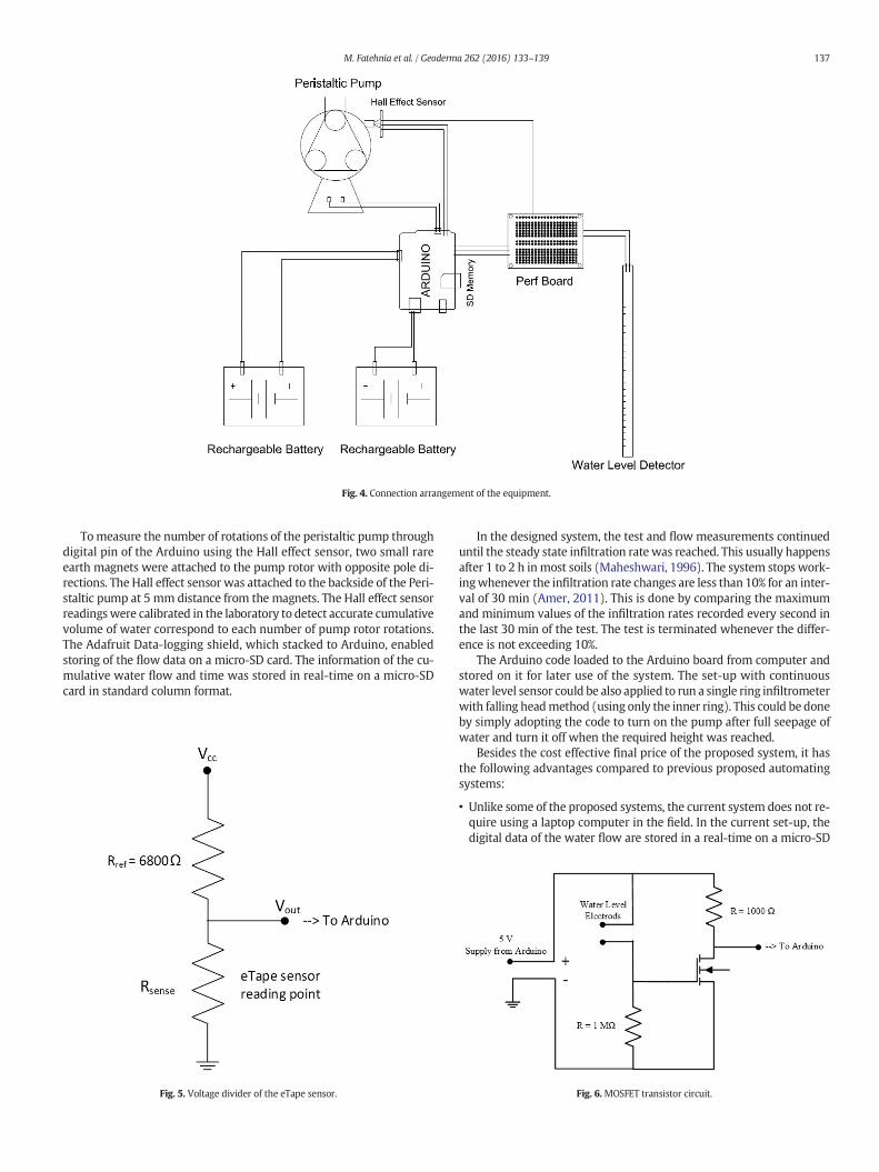
Fig. 4. Connection arrangement of the equipment.
137M. Fatehnia et al. / Geoderma 262 (2016) 133–139
Tomeasure the number of rotations of the peristaltic pump throughdigital pin of the Arduino using the Hall effect sensor, two small rareearth magnets were attached to the pump rotor with opposite pole di-rections. The Hall effect sensor was attached to the backside of the Peri-staltic pump at 5 mm distance from the magnets. The Hall effect sensorreadingswere calibrated in the laboratory to detect accurate cumulativevolume of water correspond to each number of pump rotor rotations.The Adafruit Data-logging shield, which stacked to Arduino, enabledstoring of the flow data on a micro-SD card. The information of the cu-mulative water flow and time was stored in real-time on a micro-SDcard in standard column format.
Fig. 5. Voltage divider of the eTape sensor.
In the designed system, the test and flow measurements continueduntil the steady state infiltration ratewas reached. This usually happensafter 1 to 2 h inmost soils (Maheshwari, 1996). The system stops work-ingwhenever the infiltration rate changes are less than 10% for an inter-val of 30 min (Amer, 2011). This is done by comparing the maximumand minimum values of the infiltration rates recorded every second inthe last 30 min of the test. The test is terminated whenever the differ-ence is not exceeding 10%.
The Arduino code loaded to the Arduino board from computer andstored on it for later use of the system. The set-up with continuouswater level sensor could be also applied to run a single ring infiltrometerwith falling headmethod (using only the inner ring). This could be doneby simply adopting the code to turn on the pump after full seepage ofwater and turn it off when the required height was reached.
Besides the cost effective final price of the proposed system, it hasthe following advantages compared to previous proposed automatingsystems:
• Unlike some of the proposed systems, the current system does not re-quire using a laptop computer in the field. In the current set-up, thedigital data of the water flow are stored in a real-time on a micro-SD
Fig. 6.MOSFET transistor circuit.

Fig. 7. Field DRI test applying the automated system.
138 M. Fatehnia et al. / Geoderma 262 (2016) 133–139
card in standard column format and can be used later for retrieval andeasy import into conventional processing and plotting software likeExcel.
• The designed set-up can be used for both single ring falling head anddouble ring constant head DRI by simply adopting the Arduino codingfor each method.
• Since we measure the flow of water that passes through the pump,unlike other methods, a single reservoir can supply the water forboth inner and outer rings.
• Automated pump shut downs when no water needs to be added tothe inner ring extend battery life well enough to survive for the testduration.
• Compared to the complication of adding additional water to Mariottesystems due to their requirement of being “sealed”, water can be easilyadded to the current system.
• As the measurements of flow are done using the Hall effect sensorattached to the pump, adding water to the reservoir does not affectthe calculations. To provide continuous supply of water to both rings,water can be added to the reservoir, whenever its level drops, withouta need of correcting the measurements.
• Using the Hall effect sensor and counting the number of pump rota-tions tomeasure theflowofwater also has the benefit of constantmea-surements in different temperatures. Unlike some other methods thatrequire precautions and calibrations for temperature or sunlight effect,measurements of this set-up is not a factor of temperature or baromet-ric pressure.
• Using the Hall effect sensor also enables precise measurements of lowinfiltration values. Since any rotation of pump corresponds to specificvolume of water, even small volumes can be detected and measuredat high precision by the sensors.
• The system can detect when the steady state infiltration has happened.This way, the test automatically stops and concludes data recording.
• This system can easily be stored in a waterproof, ruggedized storagecontainer. This is very desirable for remote data logging in an outdoorenvironment.
Table 2Comparison of the automated and manual DRI experiments.
Test location Test format Maximuminfiltrationrate (cm/s)
Steady infiltrationrate (cm/s)
Florida State UniversityReservation
Automated system 3.35 × 10⁻² 1.93 × 10⁻²
Manual testing 3.50 × 10⁻² 1.85 × 10⁻²
Tallahassee regionalairport
Automated system 6.63 × 10⁻³ 4.33 × 10⁻³
Manual testing 6.50 × 10⁻³ 4.60 × 10⁻³
Greenway, Tallahassee Automated system 1.93 × 10⁻³ 1.42 × 10⁻³
Manual testing 1.70 × 10⁻³ 1.20 × 10⁻³
4. System testing and results
In order to check the accuracy of the automated system, three sets oftests were conducted at different locations with different soil materials.For comparison purposes, at each test location, a manual and an auto-mated DRI test were performed. In each location, we ran the automatedandmanual testswith enough of a separation distance to avoid interfer-ence of thewet fronts. The DRI field experiments, as shown in Fig. 7, had20 cm inner and 40 cm outer ring diameters with ring depths of 10 cm.Themeasured steady state infiltration rates and initial infiltration valuesfor bothmethods were measured afterwards using the recorded resultsof the flow. The values were compared for each set of tests. These dataare plotted in Table 2. The automatic test results showed no irregularityin the infiltration from the pump response. After each experiment,granulometric analyses were performed on the field soil samplesaccording to ASTM D 422-02 (ASTM, 2007).
The first testing location was the FSU Reservation area in Tallahas-see, Florida. The light brown sand of the test site could be described aswell-sorted, fine to coarse sand. It was categorized as SW based onUnified, and A-3 in AASHTO soil classification systems. The test sitehad a gently sloping surface (2–4°). A nearly constant infiltration rateover the 40–60minute test runwas produced by relatively high perme-ability of this soil. Graphs of cumulative infiltration rate versus time forautomated and manual tests performed in this location are provided inFig. 8. The second test locationwas in the vicinity of Tallahassee regionalairport area. The surface soil material included mottled dark and lightbrown medium to fine sand that was classified as SP-SM based onUnified and A-3 in AASHTO soil classification systems. The test site
had a gentle slope of 3–5°. The last set of tests were conducted inGreen-way, Tallahassee area. The surface material was mottled light brownand reddish brown or light gray clayey fine sand that classified as SCin unified and A-2-4 in AASHTO soil classification systems. Soil surfacehad a 2–4° slope.
By comparing the information of the manual and automatic DRI ex-periments provided in Table 2, acceptable performance of the automat-ed system is revealed. The obvious advantage of the system is that it canaccurately detect when the steady state infiltration rate has reached.
5. Conclusion
The double-ring infiltrometers are widely used for in situ measure-ment of field saturated hydraulic conductivity. In this paper, an auto-mated double ring infiltrometer was developed by using a peristalticpump, a water level sensor and a microcontroller. The system automat-ically runs the test, concludes the process when steady state is reached,and records the infiltration data on a micro-SD card. The system wasmounted in a portable and weather resistant box that can be easilyused in the field. The overall system architecture, and the design of
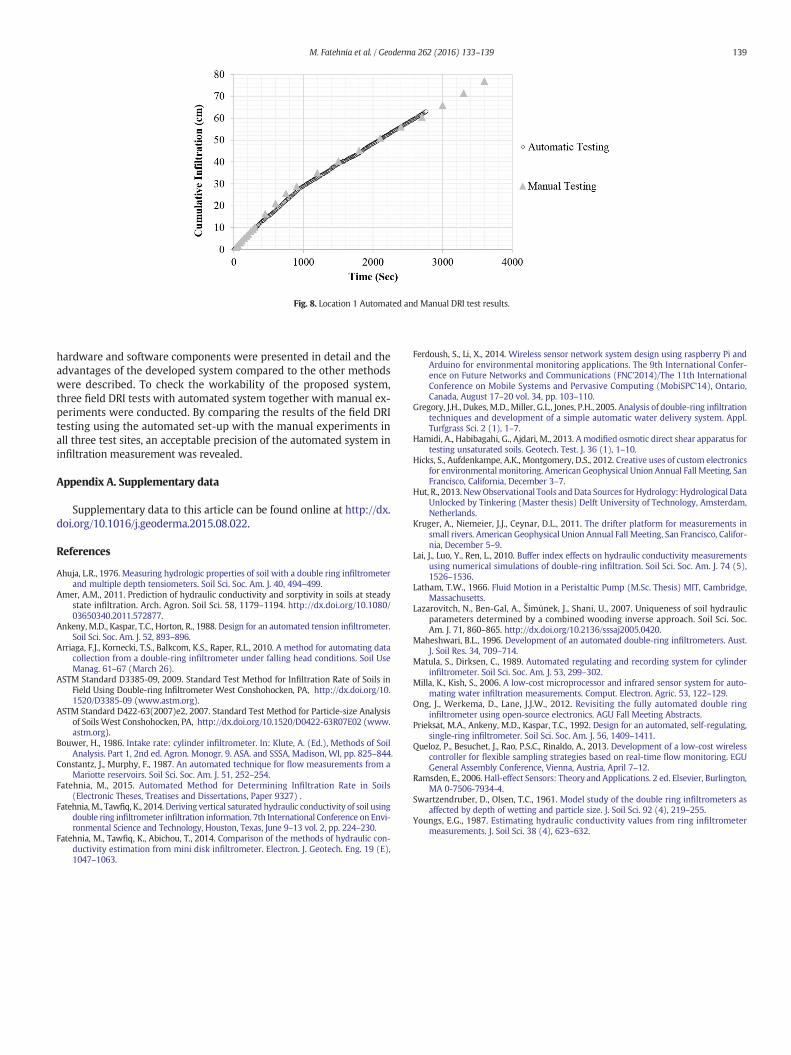
Fig. 8. Location 1 Automated and Manual DRI test results.
139M. Fatehnia et al. / Geoderma 262 (2016) 133–139
hardware and software components were presented in detail and theadvantages of the developed system compared to the other methodswere described. To check the workability of the proposed system,three field DRI tests with automated system together with manual ex-periments were conducted. By comparing the results of the field DRItesting using the automated set-up with the manual experiments inall three test sites, an acceptable precision of the automated system ininfiltration measurement was revealed.
Appendix A. Supplementary data
Supplementary data to this article can be found online at http://dx.doi.org/10.1016/j.geoderma.2015.08.022.
References
Ahuja, L.R., 1976. Measuring hydrologic properties of soil with a double ring infiltrometerand multiple depth tensiometers. Soil Sci. Soc. Am. J. 40, 494–499.
Amer, A.M., 2011. Prediction of hydraulic conductivity and sorptivity in soils at steadystate infiltration. Arch. Agron. Soil Sci. 58, 1179–1194. http://dx.doi.org/10.1080/03650340.2011.572877.
Ankeny, M.D., Kaspar, T.C., Horton, R., 1988. Design for an automated tension infiltrometer.Soil Sci. Soc. Am. J. 52, 893–896.
Arriaga, F.J., Kornecki, T.S., Balkcom, K.S., Raper, R.L., 2010. A method for automating datacollection from a double-ring infiltrometer under falling head conditions. Soil UseManag. 61–67 (March 26).
ASTM Standard D3385-09, 2009. Standard Test Method for Infiltration Rate of Soils inField Using Double-ring Infiltrometer West Conshohocken, PA, http://dx.doi.org/10.1520/D3385-09 (www.astm.org).
ASTM Standard D422-63(2007)e2, 2007. Standard Test Method for Particle-size Analysisof Soils West Conshohocken, PA, http://dx.doi.org/10.1520/D0422-63R07E02 (www.astm.org).
Bouwer, H., 1986. Intake rate: cylinder infiltrometer. In: Klute, A. (Ed.), Methods of SoilAnalysis. Part 1, 2nd ed. Agron. Monogr. 9. ASA. and SSSA, Madison, WI, pp. 825–844.
Constantz, J., Murphy, F., 1987. An automated technique for flow measurements from aMariotte reservoirs. Soil Sci. Soc. Am. J. 51, 252–254.
Fatehnia, M., 2015. Automated Method for Determining Infiltration Rate in Soils(Electronic Theses, Treatises and Dissertations, Paper 9327) .
Fatehnia,M., Tawfiq, K., 2014. Deriving vertical saturated hydraulic conductivity of soil usingdouble ring infiltrometer infiltration information. 7th International Conference on Envi-ronmental Science and Technology, Houston, Texas, June 9–13 vol. 2, pp. 224–230.
Fatehnia, M., Tawfiq, K., Abichou, T., 2014. Comparison of the methods of hydraulic con-ductivity estimation from mini disk infiltrometer. Electron. J. Geotech. Eng. 19 (E),1047–1063.
Ferdoush, S., Li, X., 2014. Wireless sensor network system design using raspberry Pi andArduino for environmental monitoring applications. The 9th International Confer-ence on Future Networks and Communications (FNC'2014)/The 11th InternationalConference on Mobile Systems and Pervasive Computing (MobiSPC'14), Ontario,Canada, August 17–20 vol. 34, pp. 103–110.
Gregory, J.H., Dukes, M.D., Miller, G.L., Jones, P.H., 2005. Analysis of double-ring infiltrationtechniques and development of a simple automatic water delivery system. Appl.Turfgrass Sci. 2 (1), 1–7.
Hamidi, A., Habibagahi, G., Ajdari, M., 2013. A modified osmotic direct shear apparatus fortesting unsaturated soils. Geotech. Test. J. 36 (1), 1–10.
Hicks, S., Aufdenkampe, A.K., Montgomery, D.S., 2012. Creative uses of custom electronicsfor environmentalmonitoring. American Geophysical Union Annual Fall Meeting, SanFrancisco, California, December 3–7.
Hut, R., 2013. NewObservational Tools andData Sources for Hydrology: Hydrological DataUnlocked by Tinkering (Master thesis) Delft University of Technology, Amsterdam,Netherlands.
Kruger, A., Niemeier, J.J., Ceynar, D.L., 2011. The drifter platform for measurements insmall rivers. American Geophysical Union Annual Fall Meeting, San Francisco, Califor-nia, December 5–9.
Lai, J., Luo, Y., Ren, L., 2010. Buffer index effects on hydraulic conductivity measurementsusing numerical simulations of double-ring infiltration. Soil Sci. Soc. Am. J. 74 (5),1526–1536.
Latham, T.W., 1966. Fluid Motion in a Peristaltic Pump (M.Sc. Thesis) MIT, Cambridge,Massachusetts.
Lazarovitch, N., Ben-Gal, A., Šimůnek, J., Shani, U., 2007. Uniqueness of soil hydraulicparameters determined by a combined wooding inverse approach. Soil Sci. Soc.Am. J. 71, 860–865. http://dx.doi.org/10.2136/sssaj2005.0420.
Maheshwari, B.L., 1996. Development of an automated double-ring infiltrometers. Aust.J. Soil Res. 34, 709–714.
Matula, S., Dirksen, C., 1989. Automated regulating and recording system for cylinderinfiltrometer. Soil Sci. Soc. Am. J. 53, 299–302.
Milla, K., Kish, S., 2006. A low-cost microprocessor and infrared sensor system for auto-mating water infiltration measurements. Comput. Electron. Agric. 53, 122–129.
Ong, J., Werkema, D., Lane, J.J.W., 2012. Revisiting the fully automated double ringinfiltrometer using open-source electronics. AGU Fall Meeting Abstracts.
Prieksat, M.A., Ankeny, M.D., Kaspar, T.C., 1992. Design for an automated, self-regulating,single-ring infiltrometer. Soil Sci. Soc. Am. J. 56, 1409–1411.
Queloz, P., Besuchet, J., Rao, P.S.C., Rinaldo, A., 2013. Development of a low-cost wirelesscontroller for flexible sampling strategies based on real-time flow monitoring. EGUGeneral Assembly Conference, Vienna, Austria, April 7–12.
Ramsden, E., 2006. Hall-effect Sensors: Theory and Applications. 2 ed. Elsevier, Burlington,MA 0-7506-7934-4.
Swartzendruber, D., Olsen, T.C., 1961. Model study of the double ring infiltrometers asaffected by depth of wetting and particle size. J. Soil Sci. 92 (4), 219–255.
Youngs, E.G., 1987. Estimating hydraulic conductivity values from ring infiltrometermeasurements. J. Soil Sci. 38 (4), 623–632.
Related Documents