Int. J. Simul. Multidisci. Des. Optim. 4, 77-83 (2010) © ASMDO 2010 DOI: 10.1051/ijsmdo/2010011 Available online at: http://www.ijsmdo.org Automatic Optimization of Air Conduct Design Using Experimental Data and Numerical Results Luis Toussaint 1,2a , Nadhir Lebaal 2 , Daniel Schlegel 2 , Samuel Gomes 2 (1) Mark IV Systèmes Moteurs, ZA Les grands près N°6, 68370 Orbey, France (2) M3M Laboratory, Université de Technologie de Belfort-Montbéliard, 90010 Belfort Cedex, France Received 15 January 2010, Accepted 30 March 2010 Abstract - The development of a new product is a process that goes through several phases, each of them requiring the ca- pitalization of data, information, knowledge and experiences gathered from previous projects. This knowledge is kept by a limited number “Experts”, and is not necessarily captured in a practical, reusable way, which translates into a loss of time and a delay for the projects. Our approach involves exporting the client’s specifications from a PLM platform and con- structing a generic product, an automotive air conduct, from them. This generic product is then fed through an optimization cycle to determine the best position and geometrical shape for all its elements. This multi-criteria optimization requires several constraints and objective functions in order to improve the part quality and process reliability needed expected by the Original Equipment Manufacturer (OEM). The need to have a design process less dependent on personal “expert” knowledge was the driving idea behind this work. The automatic optimization of the design of an air conduct still remains a challenge and the purpose of this work is to contribute to the development of an automatic design tools capable of doing this. Keywords - Design for Manufacturing, Optimization, Knowledge Based Engineering, Simulation. a Corresponding author: [email protected] 1 Introduction Designing a product, from the definition of the client’s needs right up to its fabrication is a process that requires time, at- tention and the capitalization of data, information, knowl- edge [1] and experiences gathered from previous projects [2, 3]. This knowledge is kept by a limited number of people, usually called “Experts” and is not necessarily capitalized in a practical, reusable way, which can be translated into a loss of time and a delay for the projects. Traditionally, an air conduct for a car engine is designed fol- lowing the Original Equipment Manufacturers (OEM) func- tional specifications, which establish the length of the line, its footprint or size to comply to and the engine’s functional clearance. The engine’s functional clearance is assured through the use of bellows within the form of the conduct. Due to the evolving nature of car engines, all these parame- ters are never standard and an expert has to validate them at every step of the design phase. These validations raise the cost and time involved in the design of an air conduct and need several iterations before reaching an optimal solution. Our approach involves exporting the client’s specifications from a PLM platform and constructing a generic conduct from them. This generic conduct is then fed through an opti- mization cycle to determine the best position and geometrical shape for all its elements, the height, fillets and angles of each element being given, we optimize the number of convo- lutions which will determine the clearance angles and the reach of the air conduct in use. These optimization cycles give out an optimal set of parameters which will enable the designer to build an air conduct which respects the OEM’s functional requirements without requiring an expert’s inter- vention at every step. 2 Expert knowledge in product develop- ment Knowledge Based Engineering (KBE) applications are a way of involving product knowledge, be it process or product related, during the design phases of said product [4]. In con- trast with traditional CAD tools, KBE applications allow the design intentions, answering the “why” and the “how” of a product to come forth, along with the description of the “what” [5]. These applications are also very promising, not only for academic purposes, but in the industrial milieu as well [6-8]. However, the development of KBE applications demands a full investment for industries using them. They have to stay simple or modular enough to facilitate their maintenance and evolution. Hew et al. [5] establish the beneficial link of KBE applica- tions with CAD modeling on three levels, the creation of 3D models, their analysis via expert tools and the modification and reutilization of these models. All KBE approaches share three common steps for their construction: • The identification of elements linked to a mathematical equation of the problem to solve. Once the technological and mechanism configurations are chosen, it is possible to describe the mechanism by a certain number of pa- rameters; • The construction of the interface and the 3D models from the parameters established in the preceding step, as well as the knowledge retained by the company; Article available at http://www.ijsmdo.org or http://dx.doi.org/10.1051/ijsmdo/2010011

Welcome message from author
This document is posted to help you gain knowledge. Please leave a comment to let me know what you think about it! Share it to your friends and learn new things together.
Transcript
Int. J. Simul. Multidisci. Des. Optim. 4, 77-83 (2010) © ASMDO 2010 DOI: 10.1051/ijsmdo/2010011
Available online at: http://www.ijsmdo.org
Automatic Optimization of Air Conduct Design Using Experimental Data and Numerical Results
Luis Toussaint 1,2a, Nadhir Lebaal2, Daniel Schlegel2, Samuel Gomes2
(1)Mark IV Systèmes Moteurs, ZA Les grands près N°6, 68370 Orbey, France (2)M3M Laboratory, Université de Technologie de Belfort-Montbéliard, 90010 Belfort Cedex, France
Received 15 January 2010, Accepted 30 March 2010
Abstract - The development of a new product is a process that goes through several phases, each of them requiring the ca-pitalization of data, information, knowledge and experiences gathered from previous projects. This knowledge is kept by a limited number “Experts”, and is not necessarily captured in a practical, reusable way, which translates into a loss of time and a delay for the projects. Our approach involves exporting the client’s specifications from a PLM platform and con-structing a generic product, an automotive air conduct, from them. This generic product is then fed through an optimization cycle to determine the best position and geometrical shape for all its elements. This multi-criteria optimization requires several constraints and objective functions in order to improve the part quality and process reliability needed expected by the Original Equipment Manufacturer (OEM). The need to have a design process less dependent on personal “expert” knowledge was the driving idea behind this work. The automatic optimization of the design of an air conduct still remains a challenge and the purpose of this work is to contribute to the development of an automatic design tools capable of doing this.
Keywords - Design for Manufacturing, Optimization, Knowledge Based Engineering, Simulation.
a Corresponding author: [email protected]
1 Introduction Designing a product, from the definition of the client’s needs right up to its fabrication is a process that requires time, at-tention and the capitalization of data, information, knowl-edge [1] and experiences gathered from previous projects [2, 3]. This knowledge is kept by a limited number of people, usually called “Experts” and is not necessarily capitalized in a practical, reusable way, which can be translated into a loss of time and a delay for the projects. Traditionally, an air conduct for a car engine is designed fol-lowing the Original Equipment Manufacturers (OEM) func-tional specifications, which establish the length of the line, its footprint or size to comply to and the engine’s functional clearance. The engine’s functional clearance is assured through the use of bellows within the form of the conduct. Due to the evolving nature of car engines, all these parame-ters are never standard and an expert has to validate them at every step of the design phase. These validations raise the cost and time involved in the design of an air conduct and need several iterations before reaching an optimal solution.
Our approach involves exporting the client’s specifications from a PLM platform and constructing a generic conduct from them. This generic conduct is then fed through an opti-mization cycle to determine the best position and geometrical shape for all its elements, the height, fillets and angles of each element being given, we optimize the number of convo-lutions which will determine the clearance angles and the reach of the air conduct in use. These optimization cycles give out an optimal set of parameters which will enable the designer to build an air conduct which respects the OEM’s
functional requirements without requiring an expert’s inter-vention at every step.
2 Expert knowledge in product develop-ment Knowledge Based Engineering (KBE) applications are a way of involving product knowledge, be it process or product related, during the design phases of said product [4]. In con-trast with traditional CAD tools, KBE applications allow the design intentions, answering the “why” and the “how” of a product to come forth, along with the description of the “what” [5]. These applications are also very promising, not only for academic purposes, but in the industrial milieu as well [6-8]. However, the development of KBE applications demands a full investment for industries using them. They have to stay simple or modular enough to facilitate their maintenance and evolution. Hew et al. [5] establish the beneficial link of KBE applica-tions with CAD modeling on three levels, the creation of 3D models, their analysis via expert tools and the modification and reutilization of these models. All KBE approaches share three common steps for their construction: • The identification of elements linked to a mathematical
equation of the problem to solve. Once the technological and mechanism configurations are chosen, it is possible to describe the mechanism by a certain number of pa-rameters;
• The construction of the interface and the 3D models from the parameters established in the preceding step, as well as the knowledge retained by the company;
Article available at http://www.ijsmdo.org or http://dx.doi.org/10.1051/ijsmdo/2010011
78 International Journal for Simulation and Multidisciplinary Design Optimization
• The interaction of the designers for the development of new products, always with the possibility of updating the knowledge retained on the models and the interface.
Examples of the use of KBE applications exist on the lit-
erature, for the development of new complex products with the aid of axiomatic design and Case Based Reasoning (CBR) [9], for the development of product catalogs with cap-tured knowledge and MOKA or CommonKADS [10], cou-pled with CAD modeling software like CATIA V5 [11]. They are also often coupled with optimization algorithms to improve the product design choices made [12]. The coupling with an optimization algorithm can effectively raise the utility of a KBE application. Since the interest of a KBE application is to involve product/process knowledge in the product’s design, the use of optimization can improve the flexibility of results obtained during the design phase. All optimization problems can be divided into five categories [12]. Each one of these favors a different interpretation of the optimization problem, which can be solve according to: • Its design variables [13, 14]; • The existence of constraints within the optimization
problem [15, 16]; • Their objective function (qualitative, quantitative, analy-
tical, etc.) [17, 18]; • The domain of the problem (single, multiple or interde-
pendent) [19]; • The environment of the optimization (completeness of
knowledge, designer implication, unknown variables, etc.) [20].
For every interpretation of an optimization problem, there is an algorithmic method of resolution that can better solve it. They can be either multi-objective, multi-modal, constrained, increasing designer confidence or dealing with real life de-sign requirements [12]. We will work with certain gradient type (Sequential Quadratic Programming – SQP and Broy-den, Fletcher, Goldfarb, Shanno – BFGS) and non-deterministic or stochastic methods (Simplex) algorithms [18] in this research paper, in order to improve the results offered by our approach. This KBE application is coupled with the FaBK methodology described in [21] in order to help designers develop better products, with more respect of design and process rules, in less time and with less effort.
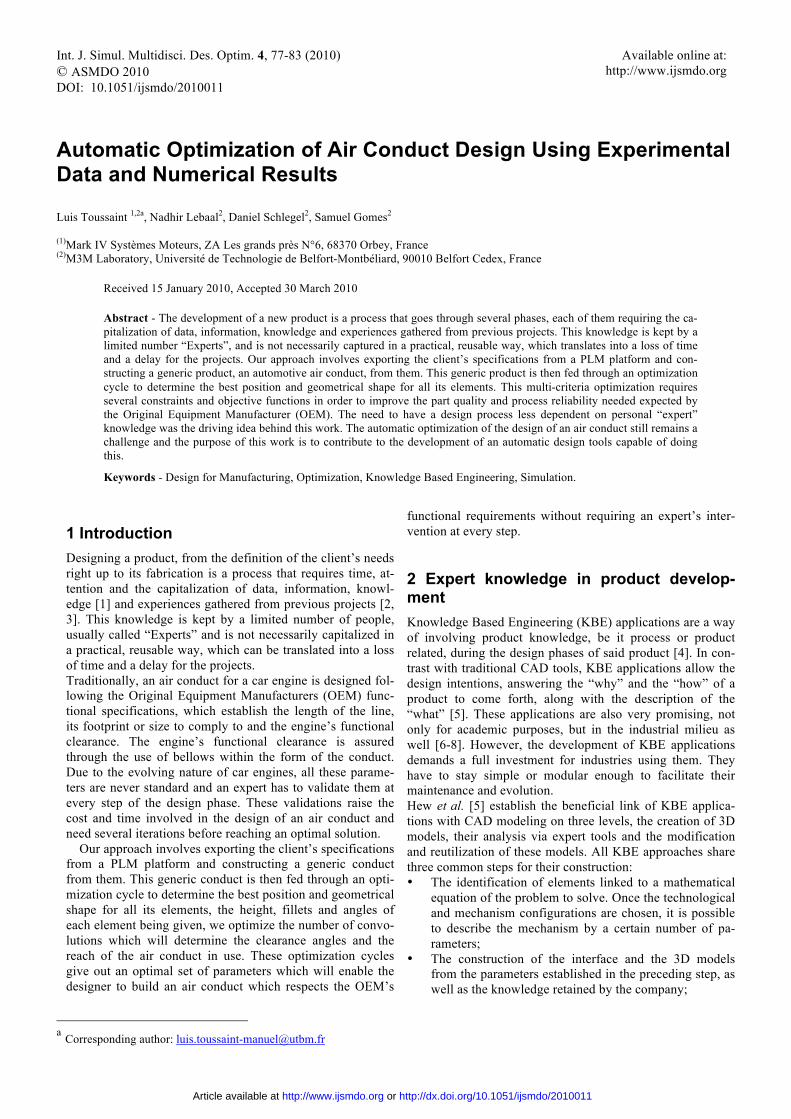
3 Product optimization and its algorithms This research paper is conducted within the R&D department of an automobile supplier, for the design of an air conduct that communicates between the radiator and the air compres-sor feeding air to the engine. When a car’s Original Equip-ment Manufacturer (OEM) makes a call for offers from a supplier, they deliver a document that lists all the specifics the product will have to fulfill in order to be accepted. They range from material requirements to validation tests, includ-ing every detail of form and function for the concept they expect. In addition to the items in this list, a rough geometri-cal envelope or form is also needed to complete the product. For the type of product this paper describes at least the gen-eral path (1), the location and orientation of its sub-elements (2) and the type of connection to the vehicle required are needed (Fig1).
Fig. 1. Client’s requirements - first draft model
One of these sub-elements, the bellows, assures the flexi-
bility of the product when the engine moves forwards and backwards through its regular function. Since the radiator is a fixed point on the chassis, and the engine oscillates between a Full Back Position (FBP) on acceleration and a Full Front Position (FFP) upon braking, the bellows maintain the in-tegrity of the conduct and allow it to deform and reach these positions. The path from the FBP to the FFP is otherwise known as the clearance. The proper geometry and exact posi-tion of these bellows is important, as it can reduce undue constraints during the production and the service of the con-duct.
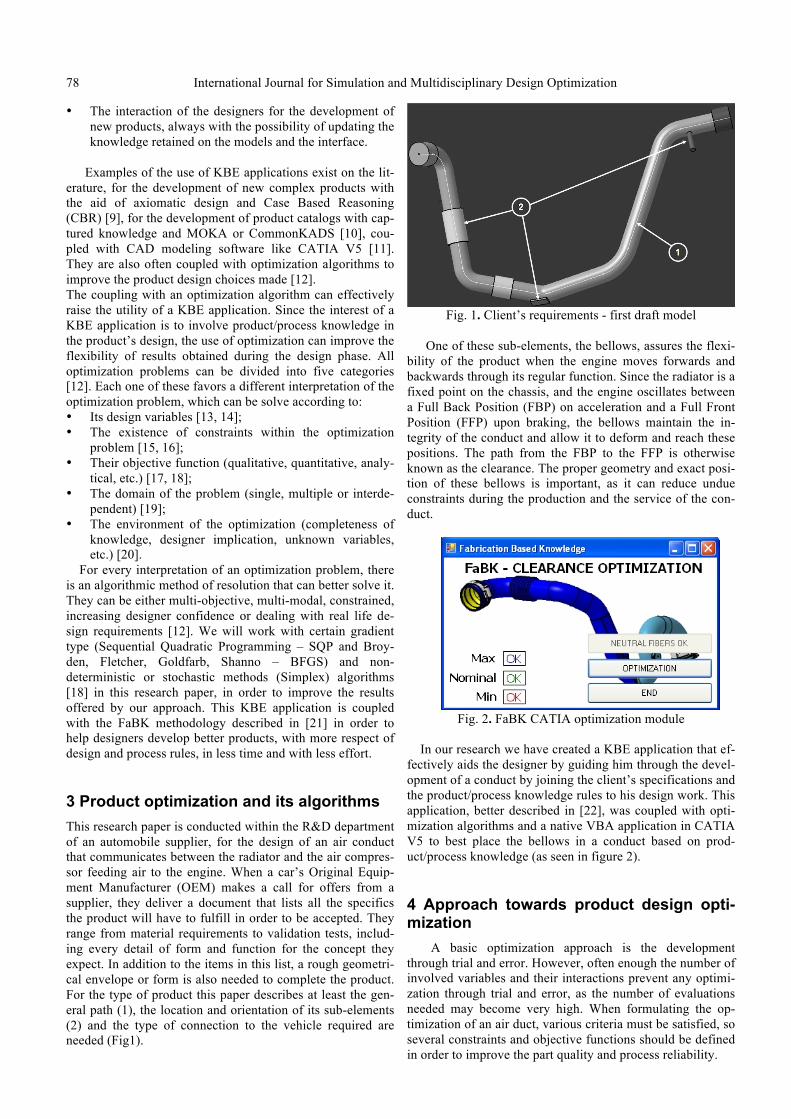
Fig. 2. FaBK CATIA optimization module
In our research we have created a KBE application that ef-
fectively aids the designer by guiding him through the devel-opment of a conduct by joining the client’s specifications and the product/process knowledge rules to his design work. This application, better described in [22], was coupled with opti-mization algorithms and a native VBA application in CATIA V5 to best place the bellows in a conduct based on prod-uct/process knowledge (as seen in figure 2).
4 Approach towards product design opti-mization
A basic optimization approach is the development through trial and error. However, often enough the number of involved variables and their interactions prevent any optimi-zation through trial and error, as the number of evaluations needed may become very high. When formulating the op-timization of an air duct, various criteria must be satisfied, so several constraints and objective functions should be defined in order to improve the part quality and process reliability.
L. Toussaint et al : Automatic Optimization of Air Conduct Design Using Experimental Data and Numerical Results 79
In the current work, an optimization problem was formu-lated to find an optimal bellows position and optimal design of the bellows geometry which allows the minimization of the development cost and respecting the clearance imposed by the OEM. In order to describe the clearance (objective function), an algorithm was developed in MATLAB, this algorithm permits the simulation of the clearance using a spherical link at each bellows.
According to the initial shape of the conduct we define neutral fiber. Once the neutral fiber is generated, a spherical link is then imposed at each bellows position. This spherical link is controlled by six optimization variables. They corres-pond to the bellows functional angles (two angles by bel-lows) obtained by the bellows geometry (number of convolu-tions) located at different heights of the air conduct and two bellows positions. The optimization variables are constrained using lower and upper bounds, corresponding respectively to the lower and upper parameters obtained by an experimental data using a design of experiment.
The choice of the optimization algorithm is closely re-lated to the type of objective function. In our application, we attempt to minimize a nonlinear real-valued function, subject to bound constraints. In addition, strong geometric nonlin-earities could induce the non linearity of the objective func-tion, but we haven’t a significant numerical instability [23], therefore the objective function is differentiable. As a conse-quence, the gradient-based algorithm is adapted to this type of problem [24]. In this work, several optimization algor-ithms are used and compared regarding the CPU time, opti-mal solution and number of functions evaluation.
5 Robust optimization based on product knowledge
In this section, we propose to couple some optimization algorithms to numerical simulations of the clearance of the air conduct in order to optimize the bellows geometry (angles). Through empirical experimentation we have deter-mined a direct link between the angle of bend required and a set of geometrical parameters that give form to the bellows. The goal will be to equal the clearance imposed by the OEM through calculations and then retrieve the geometrical pa-rameters that assure this clearance.
For this an optimization problem (P) was formulated to find an optimal angle for the bellows which guarantees the clearance between the FFP and FBP positions of the engine imposed by the OEM.
The optimization problem is formulated as follows:
(1)
5.1 Parameterization and Constraints
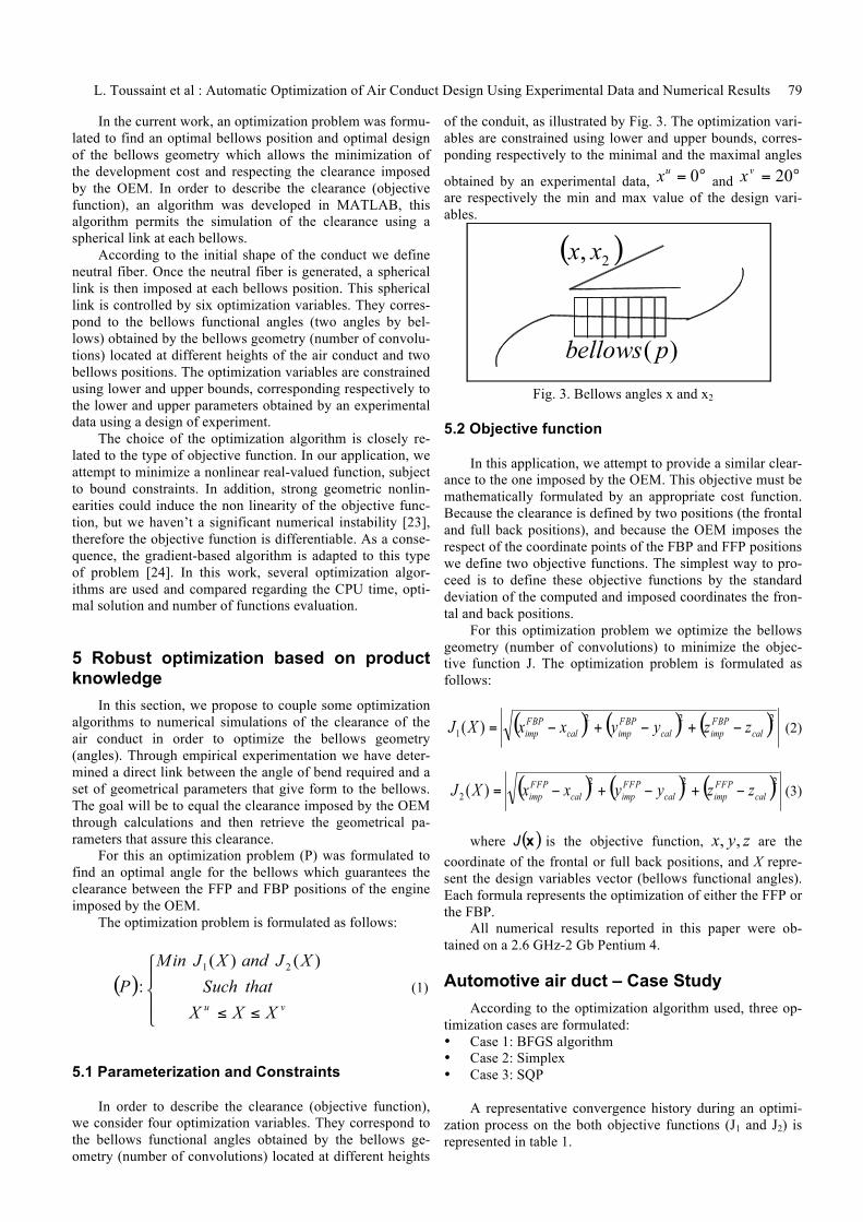
In order to describe the clearance (objective function), we consider four optimization variables. They correspond to the bellows functional angles obtained by the bellows ge-ometry (number of convolutions) located at different heights
of the conduit, as illustrated by Fig. 3. The optimization vari-ables are constrained using lower and upper bounds, corres-ponding respectively to the minimal and the maximal angles
obtained by an experimental data, and are respectively the min and max value of the design vari-ables.
Fig. 3. Bellows angles x and x2
5.2 Objective function
In this application, we attempt to provide a similar clear-ance to the one imposed by the OEM. This objective must be mathematically formulated by an appropriate cost function. Because the clearance is defined by two positions (the frontal and full back positions), and because the OEM imposes the respect of the coordinate points of the FBP and FFP positions we define two objective functions. The simplest way to pro-ceed is to define these objective functions by the standard deviation of the computed and imposed coordinates the fron-tal and back positions.
For this optimization problem we optimize the bellows geometry (number of convolutions) to minimize the objec-tive function J. The optimization problem is formulated as follows:
(2)
(3)
where is the objective function, are the
coordinate of the frontal or full back positions, and X repre-sent the design variables vector (bellows functional angles). Each formula represents the optimization of either the FFP or the FBP.
All numerical results reported in this paper were ob-tained on a 2.6 GHz-2 Gb Pentium 4.
Automotive air duct – Case Study According to the optimization algorithm used, three op-
timization cases are formulated: • Case 1: BFGS algorithm • Case 2: Simplex • Case 3: SQP
A representative convergence history during an optimi-
zation process on the both objective functions (J1 and J2) is represented in table 1.
80 International Journal for Simulation and Multidisciplinary Design Optimization
Table 1: BFGS iterations converging towards 0 BFGS
Iteration J1 J2 Iteration J1 J2
1 193.991 44.0619 19 0.0132765 0.125377
2 70.6264 40.2027 20 0.00809803 0.0657592
3 31.3168 35.481 21 0.00438403 0.0378795
4 20.9375 34.9968 22 0.00243004 0.0231421
5 17.287 34.7887 23 0.00148619 0.0137858
6 16.5466 34.5106 24 0.000921544 0.00825104
7 12.6317 33.2837 25 0.000555993 0.00445277
8 7.28338 30.0027 26 0.000311855 0.00263807
9 2.98848 21.8941 27 0.000181649 0.00161385
10 1.73986 15.9233 28 0.000178322 0.000947654
11 1.01979 7.42503 29 7.1908e-005 0.000548009
12 0.545869 4.87194 30 6.15485e-005 0.000305545
13 0.292263 2.81168 31 4.88144e-005 0.000187385
14 0.186999 1.90315 32 0.000161301
15 0.118748 1.00296 33 0.000160178
16 0.0669474 0.556147 34 0.000110312
17 0.0356434 0.329875 35 7.89125e-005
18 0.0208356 0.195604 36 6.26737e-005
After ten iterations, the objective function approaches
the zero value. And at the iteration thirty the objective func-tion falls below the cut-off threshold of 10−8 and the simula-tion stops with a reduction of 99.99 % of the objective func-tion’s initial value (193mm).
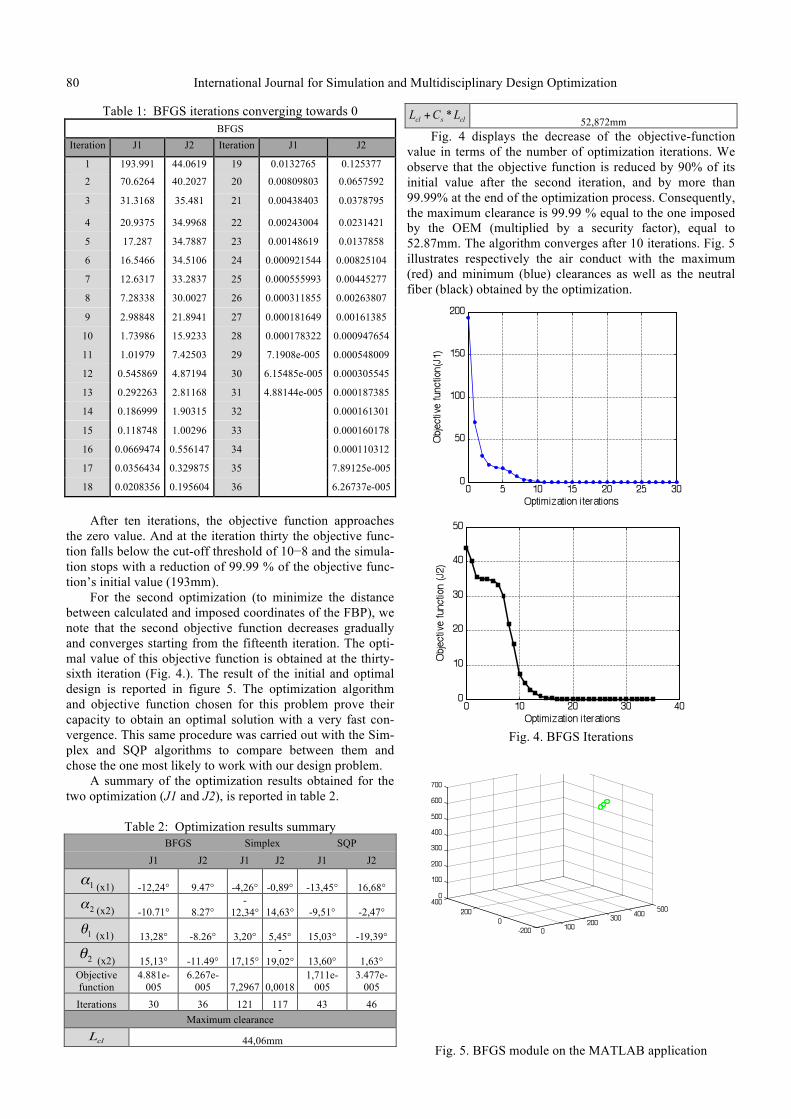
For the second optimization (to minimize the distance between calculated and imposed coordinates of the FBP), we note that the second objective function decreases gradually and converges starting from the fifteenth iteration. The opti-mal value of this objective function is obtained at the thirty-sixth iteration (Fig. 4.). The result of the initial and optimal design is reported in figure 5. The optimization algorithm and objective function chosen for this problem prove their capacity to obtain an optimal solution with a very fast con-vergence. This same procedure was carried out with the Sim-plex and SQP algorithms to compare between them and chose the one most likely to work with our design problem.
A summary of the optimization results obtained for the two optimization (J1 and J2), is reported in table 2.
Table 2: Optimization results summary
BFGS Simplex SQP J1 J2 J1 J2 J1 J2
(x1) -12,24° 9.47° -4,26° -0,89° -13,45° 16,68°
(x2) -10.71° 8.27° -
12,34° 14,63° -9,51° -2,47°
(x1) 13,28° -8.26° 3,20° 5,45° 15,03° -19,39°
(x2) 15,13° -11.49° 17,15° -
19,02° 13,60° 1,63° Objective function
4.881e-005
6.267e-005 7,2967 0,0018
1,711e-005
3.477e-005
Iterations 30 36 121 117 43 46 Maximum clearance
44,06mm
52,872mm Fig. 4 displays the decrease of the objective-function
value in terms of the number of optimization iterations. We observe that the objective function is reduced by 90% of its initial value after the second iteration, and by more than 99.99% at the end of the optimization process. Consequently, the maximum clearance is 99.99 % equal to the one imposed by the OEM (multiplied by a security factor), equal to 52.87mm. The algorithm converges after 10 iterations. Fig. 5 illustrates respectively the air conduct with the maximum (red) and minimum (blue) clearances as well as the neutral fiber (black) obtained by the optimization.
Fig. 4. BFGS Iterations
Fig. 5. BFGS module on the MATLAB application
L. Toussaint et al : Automatic Optimization of Air Conduct Design Using Experimental Data and Numerical Results 81
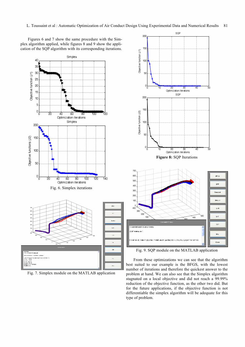
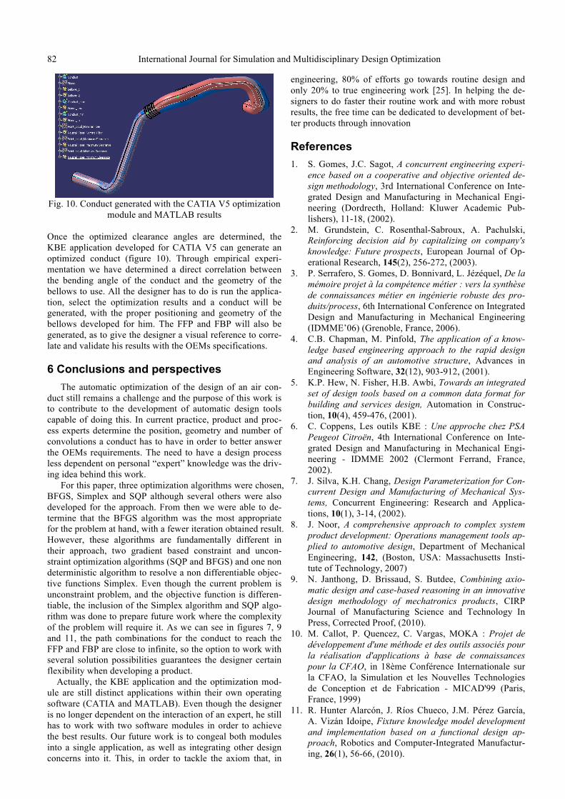
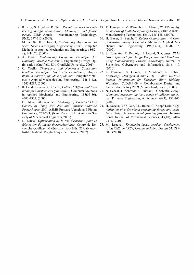
Figures 6 and 7 show the same procedure with the Sim-
plex algorithm applied, while figures 8 and 9 show the appli-cation of the SQP algorithm with its corresponding iterations.
Fig. 6. Simplex iterations
Fig. 7. Simplex module on the MATLAB application
Figure 8: SQP Iterations
Fig. 9. SQP module on the MATLAB application
From these optimizations we can see that the algorithm
best suited to our example is the BFGS, with the lowest number of iterations and therefore the quickest answer to the problem at hand. We can also see that the Simplex algorithm stagnated on a local objective and did not reach a 99.99% reduction of the objective function, as the other two did. But for the future applications, if the objective function is not differentiable the simplex algorithm will be adequate for this type of problem.
82 International Journal for Simulation and Multidisciplinary Design Optimization
Fig. 10. Conduct generated with the CATIA V5 optimization
module and MATLAB results
Once the optimized clearance angles are determined, the KBE application developed for CATIA V5 can generate an optimized conduct (figure 10). Through empirical experi-mentation we have determined a direct correlation between the bending angle of the conduct and the geometry of the bellows to use. All the designer has to do is run the applica-tion, select the optimization results and a conduct will be generated, with the proper positioning and geometry of the bellows developed for him. The FFP and FBP will also be generated, as to give the designer a visual reference to corre-late and validate his results with the OEMs specifications.
6 Conclusions and perspectives The automatic optimization of the design of an air con-
duct still remains a challenge and the purpose of this work is to contribute to the development of automatic design tools capable of doing this. In current practice, product and proc-ess experts determine the position, geometry and number of convolutions a conduct has to have in order to better answer the OEMs requirements. The need to have a design process less dependent on personal “expert” knowledge was the driv-ing idea behind this work.
For this paper, three optimization algorithms were chosen, BFGS, Simplex and SQP although several others were also developed for the approach. From then we were able to de-termine that the BFGS algorithm was the most appropriate for the problem at hand, with a fewer iteration obtained result. However, these algorithms are fundamentally different in their approach, two gradient based constraint and uncon-straint optimization algorithms (SQP and BFGS) and one non deterministic algorithm to resolve a non differentiable objec-tive functions Simplex. Even though the current problem is unconstraint problem, and the objective function is differen-tiable, the inclusion of the Simplex algorithm and SQP algo-rithm was done to prepare future work where the complexity of the problem will require it. As we can see in figures 7, 9 and 11, the path combinations for the conduct to reach the FFP and FBP are close to infinite, so the option to work with several solution possibilities guarantees the designer certain flexibility when developing a product.
Actually, the KBE application and the optimization mod-ule are still distinct applications within their own operating software (CATIA and MATLAB). Even though the designer is no longer dependent on the interaction of an expert, he still has to work with two software modules in order to achieve the best results. Our future work is to congeal both modules into a single application, as well as integrating other design concerns into it. This, in order to tackle the axiom that, in
engineering, 80% of efforts go towards routine design and only 20% to true engineering work [25]. In helping the de-signers to do faster their routine work and with more robust results, the free time can be dedicated to development of bet-ter products through innovation
References 1. S. Gomes, J.C. Sagot, A concurrent engineering experi-
ence based on a cooperative and objective oriented de-sign methodology, 3rd International Conference on Inte-grated Design and Manufacturing in Mechanical Engi-neering (Dordrecth, Holland: Kluwer Academic Pub-lishers), 11-18, (2002).
2. M. Grundstein, C. Rosenthal-Sabroux, A. Pachulski, Reinforcing decision aid by capitalizing on company's knowledge: Future prospects, European Journal of Op-erational Research, 145(2), 256-272, (2003).
3. P. Serrafero, S. Gomes, D. Bonnivard, L. Jézéquel, De la mémoire projet à la compétence métier : vers la synthèse de connaissances métier en ingénierie robuste des pro-duits/process, 6th International Conference on Integrated Design and Manufacturing in Mechanical Engineering (IDMME’06) (Grenoble, France, 2006).
4. C.B. Chapman, M. Pinfold, The application of a know-ledge based engineering approach to the rapid design and analysis of an automotive structure, Advances in Engineering Software, 32(12), 903-912, (2001).
5. K.P. Hew, N. Fisher, H.B. Awbi, Towards an integrated set of design tools based on a common data format for building and services design, Automation in Construc-tion, 10(4), 459-476, (2001).
6. C. Coppens, Les outils KBE : Une approche chez PSA Peugeot Citroën, 4th International Conference on Inte-grated Design and Manufacturing in Mechanical Engi-neering - IDMME 2002 (Clermont Ferrand, France, 2002).
7. J. Silva, K.H. Chang, Design Parameterization for Con-current Design and Manufacturing of Mechanical Sys-tems, Concurrent Engineering: Research and Applica-tions, 10(1), 3-14, (2002).
8. J. Noor, A comprehensive approach to complex system product development: Operations management tools ap-plied to automotive design, Department of Mechanical Engineering, 142, (Boston, USA: Massachusetts Insti-tute of Technology, 2007)
9. N. Janthong, D. Brissaud, S. Butdee, Combining axio-matic design and case-based reasoning in an innovative design methodology of mechatronics products, CIRP Journal of Manufacturing Science and Technology In Press, Corrected Proof, (2010).
10. M. Callot, P. Quencez, C. Vargas, MOKA : Projet de développement d'une méthode et des outils associés pour la réalisation d'applications à base de connaissances pour la CFAO, in 18ème Conférence Internationale sur la CFAO, la Simulation et les Nouvelles Technologies de Conception et de Fabrication - MICAD'99 (Paris, France, 1999)
11. R. Hunter Alarcón, J. Ríos Chueco, J.M. Pérez García, A. Vizán Idoipe, Fixture knowledge model development and implementation based on a functional design ap-proach, Robotics and Computer-Integrated Manufactur-ing, 26(1), 56-66, (2010).
L. Toussaint et al : Automatic Optimization of Air Conduct Design Using Experimental Data and Numerical Results 83
12. R. Roy, S. Hinduja, R. Teti, Recent advances in engi-neering design optimisation: Challenges and future trends, CIRP Annals - Manufacturing Technology, 57(2), 697-715, (2008).
13. M. Schütz, H. Schwefel, Evolutionary Approaches to Solve Three Challenging Engineering Tasks, Computer Methods in Applied Mechanics and Engineering, 186(2-4), 141-170, (2000).
14. A. Tiwari, Evolutionary Computing Techniques for Handling Variable Interaction, Engineering Design Op-timisation (Cranfield, UK: Cranfield University, 2001).
15. C. Coello, Theoretical and Numerical Constraitn-handling Techniques Used with Evolutionary Algor-ithms: A survey of the State of the Art, Computer Meth-ods in Applied Mechanics and Engineering, 191(11-12), 1245-1287, (2002).
16. R. Landa Becerra, C. Coello, Cultured Differential Evo-lution for Constrained Optimization, Computer Methods in Applied Mechanics and Engineering, 195(33-36), 4303-4322, (2007).
17. E. Shkvar, Mathematical Modeling of Turbulent Flow Control by Using Wall Jets and Polymer Additives Poster Paper, 2001 ASME Pressure Vessels and Piping Conference, 277-283, (New York, USA: American So-ciety of Mechanical Engineers, 2001)
18. N. Lebaal, Optimisation de la tête d'extrusion pour la fabrication de pièces thermoplastiques, Centre de Re-cherche Outillage, Matériaux et Procédés, 219, (Nancy: Institut National Polytechnique de Lorraine, 2007)
19. T. Tomiyama, V. D'Amelio, J. Urbanic, W. ElMaraghy, Complexity of Multi-Disciplinary Design, CIRP Annals - Manufacturing Technology, 56(1), 185-188, (2007).
20. H. Beyer, B. Sendhoff, Robust Optimization - A Com-prehensive Survey, Computer Methods, Applied Me-chanics and Engineering, 196(33-34), 3190-3218, (2007).
21. L. Toussaint, F. Demoly, N. Lebaal, S. Gomes, PLM-based Approach for Design Verification and Validation using Manufacturing Process Knowledge, Journal of Systemics, Cybernetics and Informatics, 8(1), 1-7, (2010).
22. L. Toussaint, S. Gomes, D. Monticolo, N. Lebaal, Knowledge Management and DFM - Future work on Design Optimization for Extrusion Blow Molding, Workshop CoDeKF’09 – Collaborative Design and Knowledge Factory 2009 (Montbéliard, France, 2009).
23. N. Lebaal, F. Schmidt, S. Puissant, D. Schläfli, Design of optimal extrusion die for a range of different materi-als, Polymer Engineering & Science, 49(3), 432-440, (2009).
24. H. Naceur, Y.Q. Guo, J.L. Batoz, C. Knopf-Lenoir, Op-timization of a drawbead restraining forces and draw-bead design in sheet metal forming process, Interna-tional Journal of Mechanical Sciences, 43(10), 2407-2434, (2001).
25. M. Rezayat, Knowledge-based product development using XML and KCs, Computer-Aided Design 32, 299-309, (2000).
Related Documents