1 AUTOMATED LIQUID FILLING SYSTEM A PROJECT REPORT SUBMITTED IN PARTIAL FULFILLMENT OF THE REQUIREMENTS FOR ELECTRONIC PRACTICALS – PHY2222 SUBMITTED TO DEPARTMENT OF PHYSICS UNIVERSITY OF RUHUNA, MATARA SUBMITTED BY R.G.G.Buddhika (SC/2012/8565) B.M.N.M.P.Kumara (SC/2012/8554) J.G.N.Jeewandara (SC/2012/8448) B.G.S.N. Bambaranda (SC/2012/8510) SUPERVISED BY Mr.S.S.Abewickrama Miss.P.D.Sakunthala 31 st December 2014

Welcome message from author
This document is posted to help you gain knowledge. Please leave a comment to let me know what you think about it! Share it to your friends and learn new things together.
Transcript
1
AUTOMATED LIQUID FILLING SYSTEM
A PROJECT REPORT
SUBMITTED IN PARTIAL FULFILLMENT OF THE REQUIREMENTS
FOR
ELECTRONIC PRACTICALS – PHY2222
SUBMITTED TO
DEPARTMENT OF PHYSICS
UNIVERSITY OF RUHUNA, MATARA
SUBMITTED BY
R.G.G.Buddhika (SC/2012/8565)
B.M.N.M.P.Kumara (SC/2012/8554)
J.G.N.Jeewandara (SC/2012/8448)
B.G.S.N. Bambaranda (SC/2012/8510)
SUPERVISED BY
Mr.S.S.Abewickrama
Miss.P.D.Sakunthala
31st December 2014
2
AUTOMATED LIQUID FILLING SYSTEM
A PROJECT REPORT
SUBMITTED IN PARTIAL FULFILLMENT OF THE REQUIREMENTS
FOR
ELECTRONIC PRACTICALS – PHY2222
SUBMITTED TO
DEPARTMENT OF PHYSICS
UNIVERSITY OF RUHUNA, MATARA
SUBMITTED BY
R.G.G.Buddhika (SC/2012/8565)
B.M.N.M.P.Kumara (SC/2012/8554)
J.G.N.Jeewandara (SC/20128/448)
B.G.S.N. Bambaranda (SC/2012/8510)
SUPERVISED BY
Mr.S.S.Abewickrama
Miss.P.D.Sakunthala
31st December 2014

3
ACKNOWLEDGEMENT
We would like to place on record my deep sense of gratitude to Dr. J.P.S.Jayathilake HOD-Dept.
of Physics, University of Ruhuna, and Matara, Sri Lanka for his generous guidance, help and
useful suggestions.
We express my sincere gratitude to Mr.S.S.Abeywickrama Dept. of Physics, University of Ruhuna,
Matara, Sri Lanka, for his stimulating guidance, continuous encouragement and supervision
throughout the course of present work.
We also wish to extend my thanks to Miss.P.D.Sakunthala and other colleagues for attending my
seminars and for their insightful comments and constructive suggestions to improve the quality of
this project work.
We am extremely thankful to non-academic staff for providing us infrastructural facilities to work
in, without which this work would not have been possible.

4
ABSTRACT
A simple automated device has been designed and constructed in order to fill the tank with
a given volume of the liquid. The sensor releases an ultrasonic wave to measure the
distance between the water level and the sensor. The water level can be adjusted by the
device and the tank will be filled up to a pre-assigned volume. The device is programmed
to switch off the tank automatically. The main advantage of this filling system is that the
tank can be filled with exact volume needed. This can be highly useful for laboratory
purposes (to take an accurate volume of a liquid). In large scale this system can be applied
to industry requirements.

5
LIST OF TABLES
Table no Description Page No
3.1 Results 12
3.2 Budget 13

6
LIST OF FIGURES
Fig 2.1 The block diagram of the Automated Liquid Filling System. ........................................................ 11
Fig 2.2 4 x 4 Keypad. ................................................................................................................................ 12
Fig 2.3 4 x4 Keypad with Arduino Board. ................................................................................................... 12
Fig 2.4 16 x 2 LCD Display. ....................................................................................................................... 13
Fig 2.5 16 x 2 LCD Display with Arduino Board. ..................................................................................... 13
Fig 2.6 Ultrasonic Sensor. .......................................................................................................................... 14
Fig 2.7 Ultrasonic Sensor with Ardunio Board. ....................................................................................... 14
Fig 2.8 Solenoid Valve. .............................................................................................................................. 15
Fig 2.9 Microcontroller. ............................................................................................................................. 16
Fig 2.10 Relay. ........................................................................................................................................ 16
Fig 2.11 Power Supply Unit. ....................................................................................................................... 17
Fig 2.12 The Flow chart of the Automated Liquid Filling System. ......................................................... 18
Fig 2.13 Circuit Diagram ........................................................................................................................... 19

7
TABLE OF CONTENTS
Page No.
Acknowledgement 3
Abstract 4
List of Tables 5
List of Figures 6
CHAPTER 1 .................................................................................................................................................... 9
INTRODUCTION ........................................................................................................................................... 9
1.1 General ................................................................................................................................................... 9
1.2 Objectives .............................................................................................................................................. 9
1.3 Features ................................................................................................................................................ 10
CHAPTER 2 .................................................................................................................................................. 11
2. MATERIALS AND METHODS ............................................................................................................... 11
2.1 Block Diagram ............................................................................................................................. 11
2.1.1 4 X 4 Keypad .................................................................................................................... 12
2.1.2 16 x 2 LCD Module .......................................................................................................... 13
2.1.3 Ultrasonic based range finder ........................................................................................... 14
2.1.4 Solenoid valve .................................................................................................................. 15
2.1.5 Microcontroller ................................................................................................................. 15
2.1.6 Relay ................................................................................................................................. 16
2.1.7 Power supply unit ............................................................................................................. 17

8
2.2 Flow Chart ........................................................................................................................................... 18
2.3 Circuit Diagram.................................................................................................................................... 19
2.4 Procedure ............................................................................................................................................. 19
CHAPTER 3 .................................................................................................................................................. 20
3 Results and Conclusion ............................................................................................................................... 20
3.1 Results .................................................................................................................................................. 20
3.2 Conclusion ........................................................................................................................................... 21
3.3 Budget .................................................................................................................................................. 21
CHAPTER 4 .................................................................................................................................................. 23
Discussion ...................................................................................................................................................... 23
4.1 Advantages ........................................................................................................................................... 23
4.2 Disadvantages ...................................................................................................................................... 23
4.3 Draw backs of the Liquid System ........................................................................................................ 23
4.3.1 Weaknesses....................................................................................................................... 23
4.3.2 Limitations ........................................................................................................................ 24
4.4 Overcomes of the Liquid System ......................................................................................................... 24
4.5 Further Development ........................................................................................................................... 24
Reference ....................................................................................................................................................... 25
Appendices ..................................................................................................................................................... 26
Data sheet of Arduino UNO ....................................................................................................................... 30

9
CHAPTER 1
INTRODUCTION
1.1 General
A simple automated device has been designed and constructed in order to fill the tank with
a given volume of the liquid. This preliminary study indicates that the ultrasonic sensor releases an
ultrasonic wave to measure the distance between the water level and the sensor. The water level
can be adjusted by the device and the tank will be filled up to that volume. The device is
programmed to switch off the solenoid automatically. Microcontroller is used to control the
automatic operation of the filling system. It is selected as the controller because it is easier to learn
and the compact size makes it easier to attach it with the system. The main advantage of this filling
system is that we can fill the tank with exact volume which is needed. This can be mainly used for
laboratory purposes (to take an accurate volume of a liquid). In large scale this system can be used
in industry.
1.2 Objectives
Develop a user friendly system by using a microcontroller as the controller so
that everyone can operate it with ease and no instructions are required.
Design the automated liquid filling system with low cost so that this can be
applied in small scale industries, to water tanks in houses, in laboratories.
Design a system that can fill the container with liquid accurately where the
specified volume desired by the user can be achieved with the smallest error
possible.
Design a system to minimize the water wastage.

10
1.3 Features
4 X 4 Keypad
16 x 2 LCD Module
Ultrasonic based range finder
Solenoid valve
11
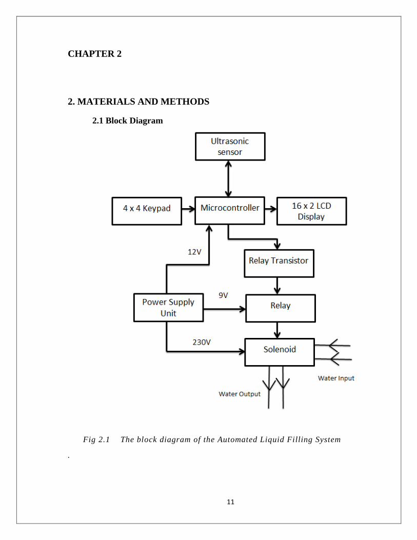
CHAPTER 2
2. MATERIALS AND METHODS
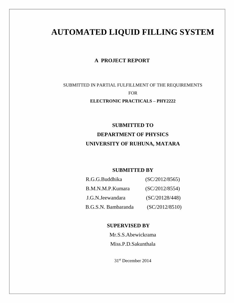
2.1 Block Diagram
Fig 2.1 The block diagram of the Automated Liquid Filling System
.
12
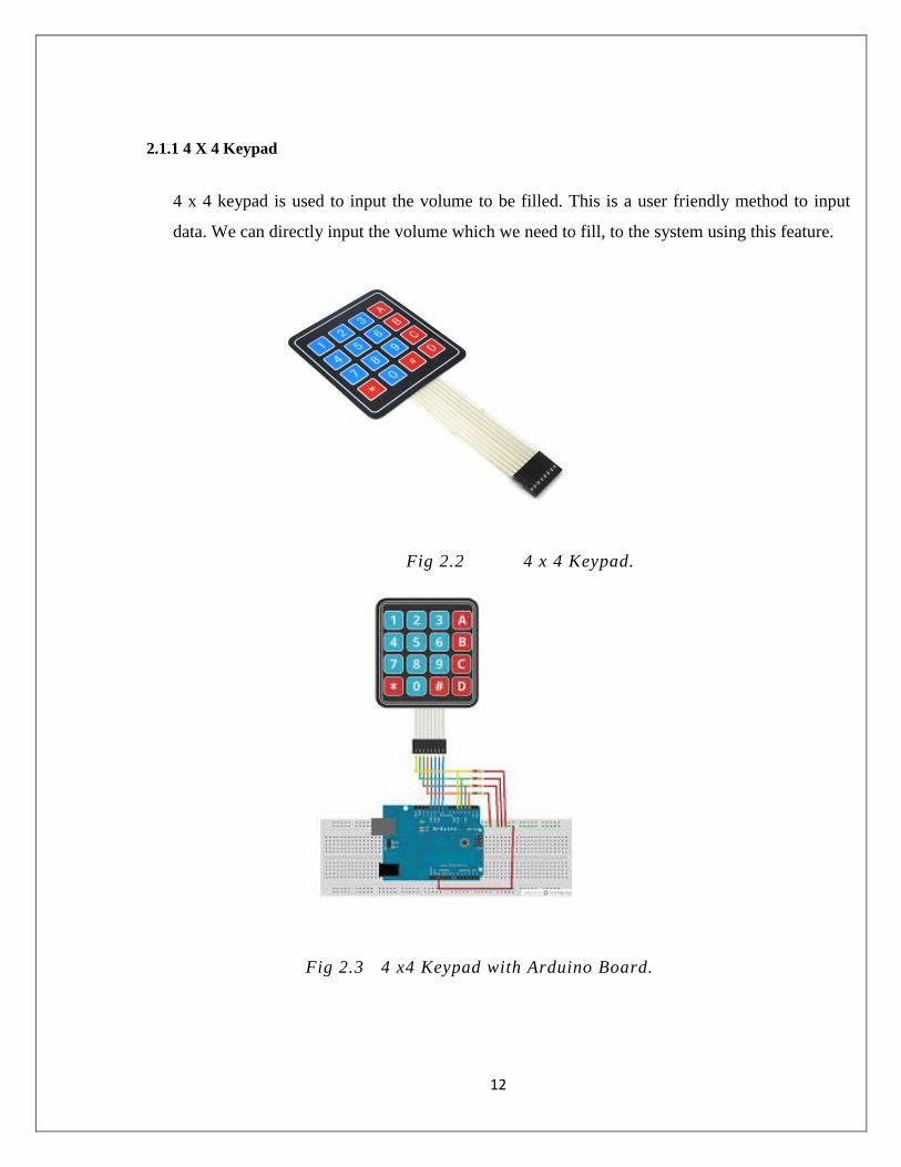
2.1.1 4 X 4 Keypad
4 x 4 keypad is used to input the volume to be filled. This is a user friendly method to input
data. We can directly input the volume which we need to fill, to the system using this feature.
Fig 2.2 4 x 4 Keypad.
Fig 2.3 4 x4 Keypad with Arduino Board.

13
2.1.2 16 x 2 LCD Module
This is a small display which displays the entered volume and when liquid is filling to the tank
it displays the current volume.
Fig 2.4 16 x 2 LCD Display.
Fig 2.5 16 x 2 LCD Display with Arduino Board.
14
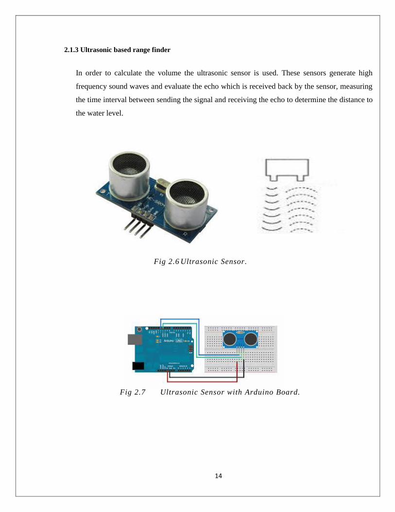
2.1.3 Ultrasonic based range finder
In order to calculate the volume the ultrasonic sensor is used. These sensors generate high
frequency sound waves and evaluate the echo which is received back by the sensor, measuring
the time interval between sending the signal and receiving the echo to determine the distance to
the water level.
Fig 2.6 Ultrasonic Sensor.
Fig 2.7 Ultrasonic Sensor with Arduino Board.

15
2.1.4 Solenoid valve
Solenoid valves control the flow of water via the automatic controller. Therefore in this
project a solenoid valve is used to control the water flow. This is controlled by a relay.
Fig 2.8 Solenoid Valve.
2.1.5 Microcontroller
Microcontroller is a small computer on a single integrated circuit containing a processor core,
memory, and programmable input/output peripherals. Program memory in the form of NOR
flash or OTP ROM is also often included on chip, as well as a typically small amount of RAM.
Microcontrollers are designed for embedded applications, in contrast to the microprocessors
used in personal computers or other general purpose applications.

16
Fig 2.9 Microcontroller.
2.1.6 Relay
A relay is an electrically operated switch. Many relays use an electromagnet to mechanically
operate a switch, but other operating principles are also used, such as solid-state relays. Relays
are used where it is necessary to control a circuit by a low-power signal (with complete
electrical isolation between control and controlled circuits), or where several circuits must be
controlled by one signal. The first relays were used in long distance telegraph circuits as
amplifiers: they repeated the signal coming in from one circuit and re-transmitted it on another
circuit.
Fig 2.10 Relay.

17
2.1.7 Power supply unit
A power supply is an electronic device that supplies electric energy to an electrical load. The
primary function of a power supply is to convert one form of electrical energy to another.
Fig 2.11 Power Supply Unit.
18
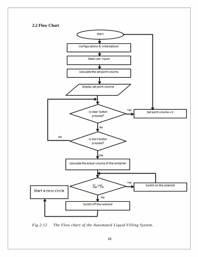
2.2 Flow Chart
Fig 2.12 The Flow chart of the Automated Liquid Filling System.

19
2.3 Circuit Diagram
Fig 2.13 Circuit Diagram
2.4 Procedure
The circuit was setup as shown in the circuit diagram. A beaker was set as the container. An
ultrasonic sensor was set at the top of the beaker and it was connected to the arduino board. Then
the solenoid was connected to a water inlet and the relay was connected to it in order to control the
solenoid. A voltage of 9 was given to the microprocessor, 12 V to the relay and 230 V to the
solenoid.

20
CHAPTER 3
3 Results and Conclusion
3.1 Results
Table (3.1)
Input (ml) Readings (ml)
200 200
300 300
400 400
500 450
600 550
700 650
800 800
900 850
1000 900
1100 1000
1200 1100
1300 1150
1400 1250
1500 1300
1600 1400
1700 1550
1800 1650
1900 1650
2000 1700
21
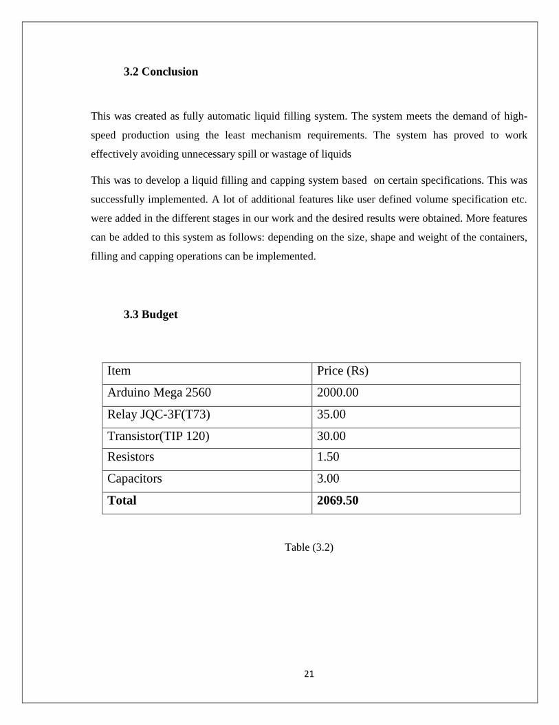
3.2 Conclusion
This was created as fully automatic liquid filling system. The system meets the demand of high-
speed production using the least mechanism requirements. The system has proved to work
effectively avoiding unnecessary spill or wastage of liquids
This was to develop a liquid filling and capping system based on certain specifications. This was
successfully implemented. A lot of additional features like user defined volume specification etc.
were added in the different stages in our work and the desired results were obtained. More features
can be added to this system as follows: depending on the size, shape and weight of the containers,
filling and capping operations can be implemented.
3.3 Budget
Item Price (Rs)
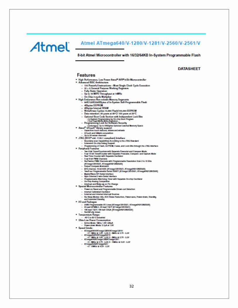
Arduino Mega 2560 2000.00
Relay JQC-3F(T73) 35.00
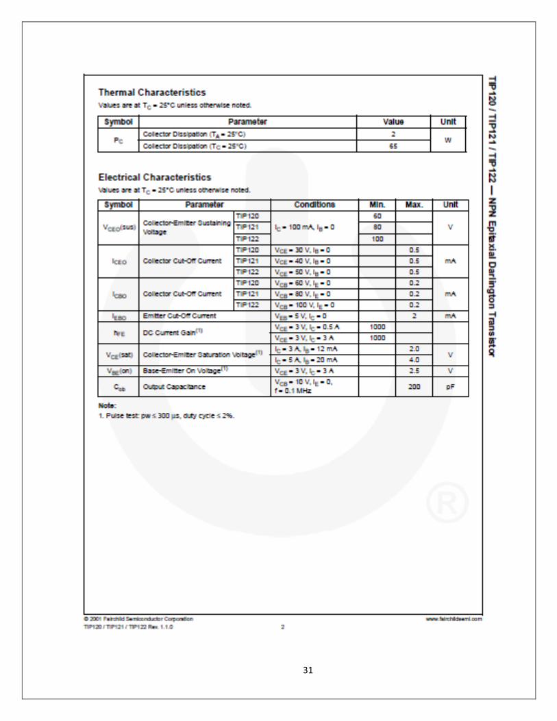
Transistor(TIP 120) 30.00
Resistors 1.50
Capacitors 3.00
Total 2069.50
Table (3.2)

22
Fig (3.1) Automated Liquid Filling System
23
CHAPTER 4
Discussion
4.1 Advantages
Can minimize water wastage.
Can specially use for laboratory purposes.
Low cost (Because of using micro controller).
Can save time.
Easy to manage.
4.2 Disadvantages
Volume is limited.
Work with 230V DC supply.
4.3 Draw backs of the Liquid System
4.3.1 Weaknesses
Accuracy of the ultrasonic sensor is low.
Velocity of sound changes with the temperature.
The speed of the water flow of solenoid is same when the current volume is near to the
required volume.
When the water is filled to the container the surface water level is not in the same level.
The shape of the beaker which is used to take the measurements is not constant.

24
4.3.2 Limitations
Volume is limited.
Work with 230V DC voltage supply.
4.4 Overcomes of the Liquid System
Can use two or more ultrasonic sensors.
Can be corrected by using temperature sensor.
Can control the speed of the water flow.
4.5 Further Development
Can use wireless controller.
Can use touch screen.

25
Reference
Shaukat.N, PLC based automatic liquid filling process, Multi Topic Conference 2002,
IEEE publications.
Dunning Gray (1998) - ‘Introduction to Programmable Logic Controllers’ - Delmar publishers,
pp.421-428.
Petruzella, Frank D. (2010) - ‘Programmable logic Controllers’ - Tata McGraw Hill
Education, pp.6-12.
Anderson, J.D. (1995) Computational Fluid Dynamics. McGraw Hill, Singapore 1995.
“THE FATHER OF INVENTION: Dick MORLEY Looks Back on The 40thannivrsery of
PLC”, Manufacture Automation September 2008
http://ieeexplore.ieee.org/xpl/articleDetails.jsp?reload=true&arnumber=1310146
http://www.industry.siemens.com/verticals/global/en/food-beverage/bev
http://www.instructables.com/file/FE5NLZMHN8245EM
http://web.cecs.pdx.edu/~eas199/B/howto/fishtank/wiring/solenoid_wiring.html
http://4tronix.co.uk/arduino/Ultra-Sonic.php
http://arduino.cc/en/uploads/Main/arduino-mega2560_R3-sch.pdf
http://arduino.cc/en/Main/arduinoBoardMega2560
26
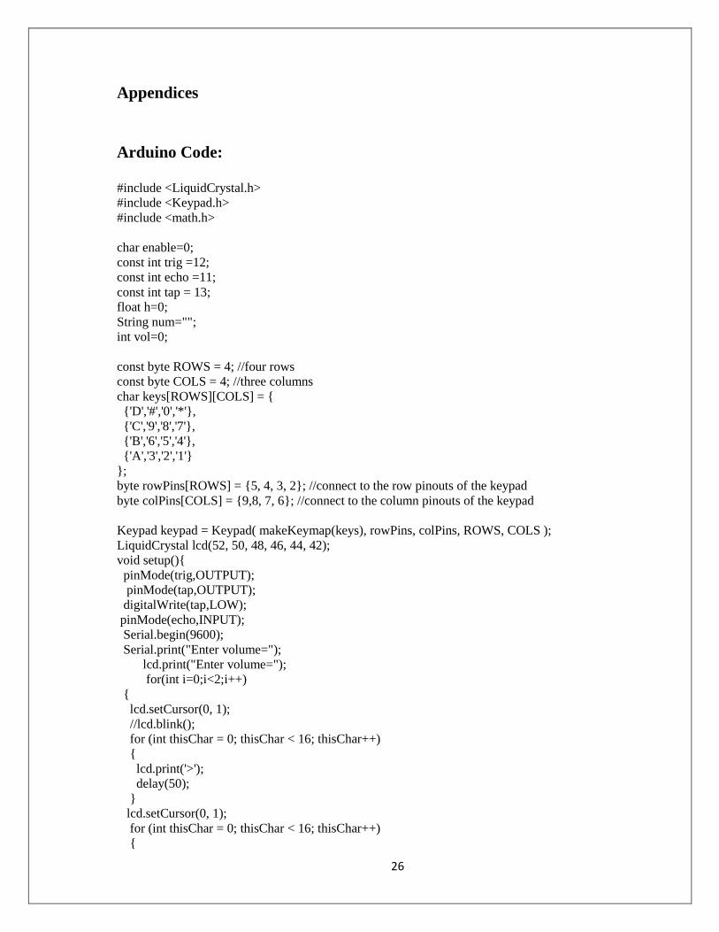
Appendices
Arduino Code:
#include <LiquidCrystal.h>
#include <Keypad.h>
#include <math.h>
char enable=0;
const int trig =12;
const int echo =11;
const int tap = 13;
float h=0;
String num="";
int vol=0;
const byte ROWS = 4; //four rows
const byte COLS = 4; //three columns
char keys[ROWS][COLS] = {
{'D','#','0','*'},
{'C','9','8','7'},
{'B','6','5','4'},
{'A','3','2','1'}
};
byte rowPins[ROWS] = {5, 4, 3, 2}; //connect to the row pinouts of the keypad
byte colPins[COLS] = {9,8, 7, 6}; //connect to the column pinouts of the keypad
Keypad keypad = Keypad( makeKeymap(keys), rowPins, colPins, ROWS, COLS );
LiquidCrystal lcd(52, 50, 48, 46, 44, 42);
void setup(){
pinMode(trig,OUTPUT);
pinMode(tap,OUTPUT);
digitalWrite(tap,LOW);
pinMode(echo,INPUT);
Serial.begin(9600);
Serial.print("Enter volume=");
lcd.print("Enter volume=");
for(int i=0;i<2;i++)
{
lcd.setCursor(0, 1);
//lcd.blink();
for (int thisChar = 0; thisChar < 16; thisChar++)
{
lcd.print('>');
delay(50);
}
lcd.setCursor(0, 1);
for (int thisChar = 0; thisChar < 16; thisChar++)
{
27
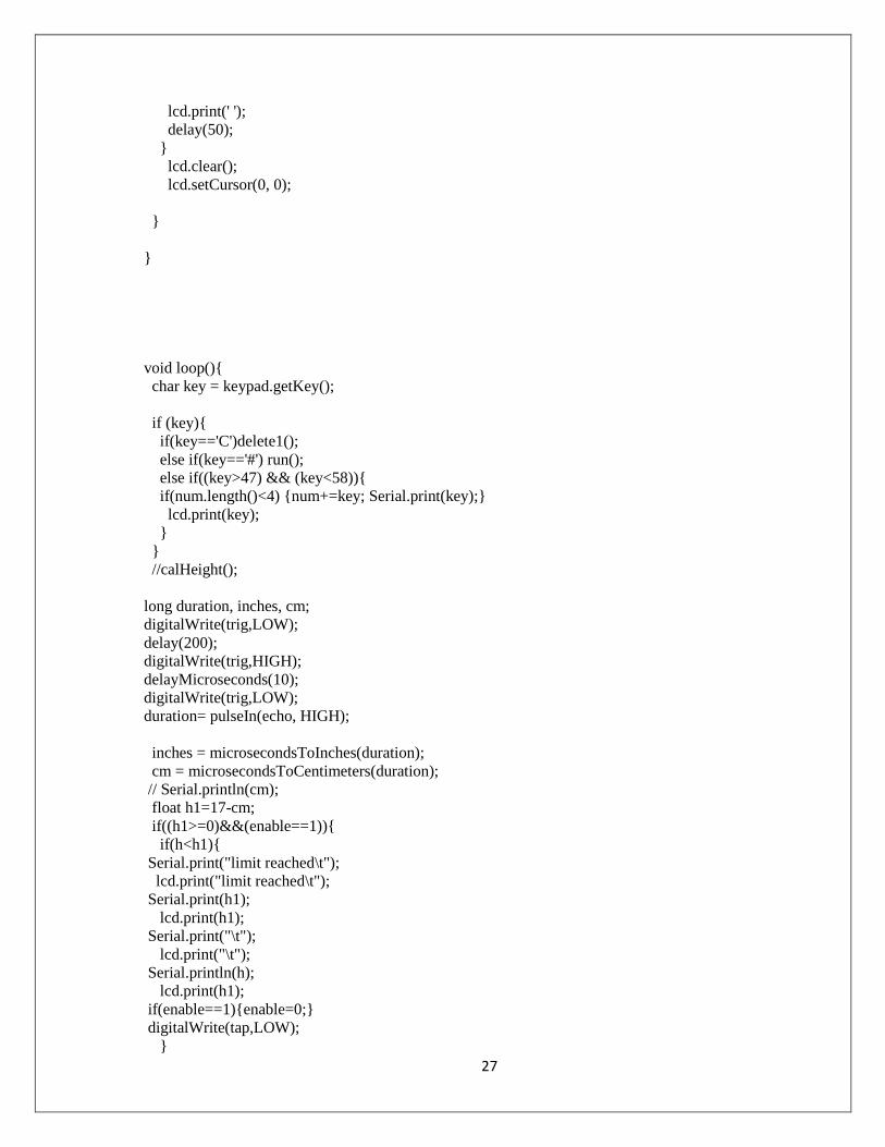
lcd.print(' ');
delay(50);
}
lcd.clear();
lcd.setCursor(0, 0);
}
}
void loop(){
char key = keypad.getKey();
if (key){
if(key=='C')delete1();
else if(key=='#') run();
else if((key>47) && (key<58)){
if(num.length()<4) {num+=key; Serial.print(key);}
lcd.print(key);
}
}
//calHeight();
long duration, inches, cm;
digitalWrite(trig,LOW);
delay(200);
digitalWrite(trig,HIGH);
delayMicroseconds(10);
digitalWrite(trig,LOW);
duration= pulseIn(echo, HIGH);
inches = microsecondsToInches(duration);
cm = microsecondsToCentimeters(duration);
// Serial.println(cm);
float h1=17-cm;
if((h1>=0)&&(enable==1)){
if(h<h1){
Serial.print("limit reached\t");
lcd.print("limit reached\t");
Serial.print(h1);
lcd.print(h1);
Serial.print("\t");
lcd.print("\t");
Serial.println(h);
lcd.print(h1);
if(enable==1){enable=0;}
digitalWrite(tap,LOW);
}

28
if(h>=h1){
Serial.print(h1);
lcd.print(h1);
Serial.print("h, ");
lcd.print("h, ");
//Serial.print(vol[cm*10]);
//Serial.print("vol");
Serial.println();
lcd.println();
if(enable==1){
digitalWrite(tap,HIGH);
}
}
}
}
void delete1()
{
Serial.println("Delete....");
lcd.print("Delete");
delay(100);
Serial.print("Enter volume=");
lcd.print("Entered volume");
num="";
}
void run()
{
//float h;
Serial.println();
lcd.println();
Serial.print("Entred volume=");
lcd.print("Entered Volume");
Serial.println(num);
lcd.print(num);
vol=num.toInt();
float height=50*(vol/50);
Serial.print("vol=");
lcd.print("Vol");
Serial.println(50*(vol/50));
h=float(height/(3.14*7.0*7.0));
Serial.print("height=");
lcd.println("height=");
Serial.println(h,2);
lcd.println(h);
enable=1;
}
/*void calHeight(){
long duration, inches, cm;
digitalWrite(trig,LOW);
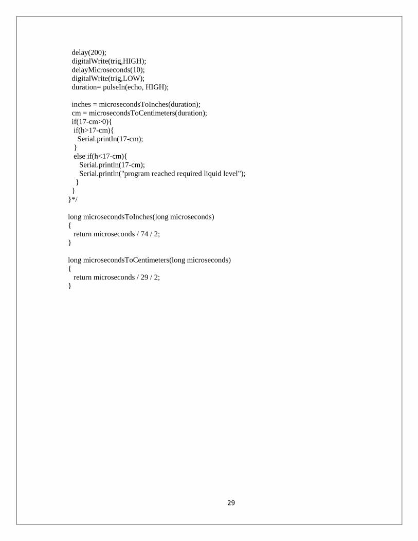
29
delay(200);
digitalWrite(trig,HIGH);
delayMicroseconds(10);
digitalWrite(trig,LOW);
duration= pulseIn(echo, HIGH);
inches = microsecondsToInches(duration);
cm = microsecondsToCentimeters(duration);
if(17-cm>0){
if(h>17-cm){
Serial.println(17-cm);
}
else if(h<17-cm){
Serial.println(17-cm);
Serial.println("program reached required liquid level");
}
}
}*/
long microsecondsToInches(long microseconds)
{
return microseconds / 74 / 2;
}
long microsecondsToCentimeters(long microseconds)
{
return microseconds / 29 / 2;
}

30
Data sheet of Arduino UNO
31
32

33

34

35
Related Documents