2012 SIMULIA Community Conference 1 Automated Industrial PTFE Billet Sintering Temperature Profile Optimization for Residual Stress Reduction Hansong Huang a , Xiangbin Yu b a Saint-Gobain Northboro R&D Center, 9 Goddard Road, Northboro, MA 01532, U.S. b Saint-Gobain Research Shanghai, No.55, Wenjing Road, Minhang, Shanghai, China Abstract: Because of its high viscosity in melted state, PTFE powder is typically first sintered as large billet, from which parts are machined such as films, seals, and etc. In large industrial sinter billet that can reach beyond 1-2 meters in size, PTFE's low thermal conductivity and large crystallization volume change could introduce significant residual stress during cool down from sinter temperature, resulting in in billet cracking and difficulties in subsequent machining step. FEA models were developed to predict the residual stress in the billet for a given temperature profile. The model was driven by iSight to minimize the cool down stage of the profile for minimal residual stress. Several optimization algorithms were compared. Entirely automated optimization workflows were then encapsulated into iSight components, with input/output exposed to end users as Excel spreadsheets. The components were then published to Simulia Execution Engine (SEE) via WebTop for remote execution. The capabilities of encapsulating simulation into “black-box” allowed the penetration of analysis into front-line design/processing engineers' daily life through dramatically reduced operation cost and improved availability. Keywords: PTFE, Sinter, Optimization, iSight, Simulia Execution Engine, Webtop, Residual Stress 1. Introduction The design and control of temperature profile – temperature vs time history – is one of the fundamental elements in wide range of material fabrication process developments, such as in glasses, polymers, crystals, and etc. Among other concerns, the accumulation of internal stress during the cooling down and the residual stress upon the process completion are main motivations for profiles design. The internal stress has to be controlled to within limits to avoid failure or unacceptable deformation. Furthermore, even with visually acceptable processed part, the residual stress could still be large enough to negatively impact downstream manufacturing process such as film skiving or part machining. In this effort, we are concerned with the optimization of temperature profile of industrial PTFE billet sintering for the purpose of residual stress minimization. We then summarize the approach to implement the optimization and simulation into processing engineers’ workflow through simulation automation.

Welcome message from author
This document is posted to help you gain knowledge. Please leave a comment to let me know what you think about it! Share it to your friends and learn new things together.
Transcript

2012 SIMULIA Community Conference 1
Automated Industrial PTFE Billet Sintering Temperature Profile Optimization for Residual
Stress Reduction
Hansong Huanga, Xiangbin Yu
b
a Saint-Gobain Northboro R&D Center, 9 Goddard Road, Northboro, MA 01532, U.S.
b Saint-Gobain Research Shanghai, No.55, Wenjing Road, Minhang, Shanghai, China
Abstract: Because of its high viscosity in melted state, PTFE powder is typically first sintered as
large billet, from which parts are machined such as films, seals, and etc. In large industrial sinter
billet that can reach beyond 1-2 meters in size, PTFE's low thermal conductivity and large
crystallization volume change could introduce significant residual stress during cool down from
sinter temperature, resulting in in billet cracking and difficulties in subsequent machining step.
FEA models were developed to predict the residual stress in the billet for a given temperature
profile. The model was driven by iSight to minimize the cool down stage of the profile for minimal
residual stress. Several optimization algorithms were compared. Entirely automated optimization
workflows were then encapsulated into iSight components, with input/output exposed to end users
as Excel spreadsheets. The components were then published to Simulia Execution Engine (SEE)
via WebTop for remote execution. The capabilities of encapsulating simulation into “black-box”
allowed the penetration of analysis into front-line design/processing engineers' daily life through
dramatically reduced operation cost and improved availability.
Keywords: PTFE, Sinter, Optimization, iSight, Simulia Execution Engine, Webtop, Residual Stress
1. Introduction
The design and control of temperature profile – temperature vs time history – is one of the
fundamental elements in wide range of material fabrication process developments, such as in
glasses, polymers, crystals, and etc. Among other concerns, the accumulation of internal stress
during the cooling down and the residual stress upon the process completion are main motivations
for profiles design. The internal stress has to be controlled to within limits to avoid failure or
unacceptable deformation. Furthermore, even with visually acceptable processed part, the residual
stress could still be large enough to negatively impact downstream manufacturing process such as
film skiving or part machining. In this effort, we are concerned with the optimization of
temperature profile of industrial PTFE billet sintering for the purpose of residual stress
minimization. We then summarize the approach to implement the optimization and simulation into
processing engineers’ workflow through simulation automation.

2 2012 SIMULIA Customer Conference
1.1 Residual stress in PTFE billet
Because of its unique mechanical and chemical properties -- such as low friction coefficient,
excellent chemical resistance, and thermal-mechanical stability -- PTFE has been widely used in
films, bearings, seals, and other industries. Due to the high viscosity in melted state, billet
sintering is the common first step in manufacturing PTFE parts (Drobny 2009). An example is
shown in Figure 1. The PTFE powder is first pre-conditioned and molded into billet under given
pressure. The de-molded green billet already has enough rigidity for handling and light machining.
A wide range of billet sizes are used in production, from less than 0.1 to more than 1 meter in
either length or diameter. The billets are then stored in temperature and humidity controlled
environment for several hours to days to allow complete degassing and relaxation. The billets are
placed in ovens and go through a sintering cycle of heat treatment (Ebnesajjad 2000). Once above
its melting temperature of around 340ºC, PTFE powder particles start to coalesce and eventually
form homogenous solid body with little porosity (Narkis 1995). The sintering temperature is
typically controlled between 360ºC to 370ºC depending on the powder and process needs, a trade-
off between sinter time and chemical stability.
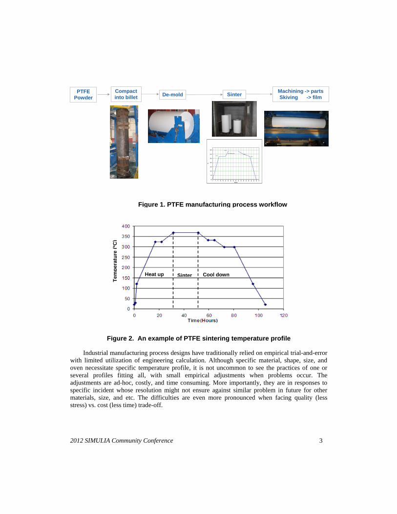
The temperature profile is carefully controlled throughout the sintering cycle. An example is
shown in Figure 2. As any temperature cycle, the profile can be divided to three stages: heat up,
sinter (constant temperature soaking), and cool down. At sintering temperature, the material is still
in semi-solid state, but possesses sufficient energy for molecular to migrate into adjacent volume.
The driving force for the sintering of all materials is the reduction of free surface energy (Mazur
1995). Nevertheless, the material transportation in polymer sintering is delivered through visco-
elastic/visco-plastic flow (Mazur 1995, Lin 2001), which is different from that of ceramics
sintering by mass diffusion (Skorokhod 1961).
One or two temperature holdings are typically inserted into heat up and cool down stages, at
temperatures close to PTFE’s melting and crystallization temperatures around 300-330ºC. The
temperature ramping rate design considers, among other constraints, the allowable temperature
gradients, degasing, capability of oven, influence on crystallinity, and accumulation of internal
residual stress (Ebnesajjad 2000, Radhakrishnan 1986). A temperature profile is described by a list
of (time, temperature) coordinates at control points, with linear ramping in between.
Internal stress inevitably occurs during the cool down stage, some of which could persist as
the residual stress after temperature gradients disappears. When residual stress becomes severe,
cracks are observed on the surfaces of billet. While other causes, such as inclusion, green body
density gradient, and degassing, also play important role, the residual stress nevertheless is the
force that drives these defects into cracks. Even without cracking, the residual stress impacts the
quality of downstream manufacturing procedures. For instance, the curvature and cracking of film
skived from the billet is directly related to the residual stresses. The dimensional precision of
machined seals cannot be achieved at the presence of large residual stresses.
The cause of residual stress, if ignoring material defects, is the inhomogeneous temperature
field inside the billet throughout the sintering cycle (Struik 1990). The temperature gradients result
in differential contraction/expansion as well as differential material property evaluation. The
residual stress is particularly pronounced in large scale industrial production PTFE billet due to
the size (> 1 meter).
2012 SIMULIA Community Conference 3
Industrial manufacturing process designs have traditionally relied on empirical trial-and-error
with limited utilization of engineering calculation. Although specific material, shape, size, and
oven necessitate specific temperature profile, it is not uncommon to see the practices of one or
several profiles fitting all, with small empirical adjustments when problems occur. The
adjustments are ad-hoc, costly, and time consuming. More importantly, they are in responses to
specific incident whose resolution might not ensure against similar problem in future for other
materials, size, and etc. The difficulties are even more pronounced when facing quality (less
stress) vs. cost (less time) trade-off.
Figure 1. PTFE manufacturing process workflow
PTFE
Powder
Compact
into billet De-mold Sinter
Machining -> parts
Skiving -> film
330°C
300°C
365°C
343°C(Melting point)
300°C
30
80
130
180
230
280
330
380
0 4 8
12
16
20
24
28
32
36
40
44
48
52
56
60
64
68
72
hours
°C
Figure 2. An example of PTFE sintering temperature profile
Heat up Sinter Cool down
Tem
pera
ture
(ºC
)

4 2012 SIMULIA Customer Conference
With the understanding of material behaviors and constitutive models, it is relatively easy
now to simulate a particular manufacturing process and predict the residual stresses under a given
scenario. Nevertheless, the design of optimal profile requires the solving of the reverse problem
through the optimization.
1.2 The critical role of automated simulation and optimization
A conventional optimization relies on the Design of Experiments (DOE) by FEA simulation
over entire feasible space. The optimization is done on the approximated response surfaces from
the DOE. The workflow is only suitable if the simulation runs very fast, and the feasible space is
fairly simple. For complex problem or time consuming simulation, the cost of DOE is prohibitive.
In an optimization driven simulation workflow, the optimization algorithm drives FEA simulation
in real time through the analysis of previous simulation results.
The wide industrial implementation of optimization driven simulation has been held back, not
by technological, but by the practicality and cost reasons -- We would argue that similar reasons
have also limited the wide spread of simulation in many smaller businesses, who see CAE
expensive and ad-hoc activities rather than core competence. We perceive the key obstacles to
great impact under limited resources allocation are:
a). Operation cost: When used in daily engineering workflow, the cost associated with FEA
analysts who execute the simulation could exceed the cost of the model development itself. The
general training of all engineers in FEA is even more costly. Hence, we often see simulation
targeted towards high value troubleshooting rather than as ingredient of routine design workflow.
b). Availability: FEA analysts and application engineers might belong to different
departments and at different locations. The long turn-around time cannot keep up with engineers’
rapid iteration cycle and forces them fall back to empirical experiences.
The solution is provided by simulation workflow automation and encapsulation, and remote
execution – the functionalities provided by iSight, SIMULIA Execution Engine, and WebTop. As
little programming is needed, any FEA analyst can effectively provide the solution via small extra
up-front development cost.
In this paper, we describe one of the efforts by Saint-Gobain Research (Northboro, MA, US
and Shanghai, China) to implement the automated, low operation cost, and highly available
simulation and optimization tools. We encapsulated the PTFE billet sintering residual stress model
in iSight components, which were driven by optimization component. Together, they were entirely
automated and published to SEE via Webtop for remote execution, with simple Excel spreadsheets
as the input and output interfaces to end users.
2. Residual Stress Calculation Model
In this exercise, we focus on the residual stresses that are primarily generated during the cool
down stage. The heat up and sinter stage of temperature profiles are kept unchanged. We also
2012 SIMULIA Community Conference 5
assume that the green body from powder compacting and degassing has homogenous density and
no internal defects.
2.1 Mechanical Properties
The PTFE green body post compacting is highly dense with typically just a few percent of
porosity. Therefore, the elastic properties of green body are assumed to be same as sintered PTFE.
The Young's modulus is taken from literature (Andena 2004) as a function of temperature (Figure
3), and Possion's ratio is assumed 0.35 constant.
The model assumes a stress free condition at the end of sinter stage which relieves the need
for an accurate model for heat up and sinter stages. The assumption is derived from the polymer
sintering mechanism of viso-plastic flow, which fully relaxes any prior stress over the long high
temperature soaking (Andena 2004, Narkis 1995). Consequently, we utilize idealized constitutive
models during heat up and sinter stage: The green body is considered as linear elastic during the
heat up stage; Once above melt temperature of 355ºC, a very low artificial yielding stress is
activated for perfect plastic flow. The low yielding stress persists into the cool down stage until
the temperature reaches into crystallization temperature between 298 ºC and 330 ºC, during which
the yielding stress increases with lower temperature. Once below 298 ºC, the literature value of
yielding stress (Andena 2004) (Figure 3) is used with elasto-perfect plasticity model. Current
model ignores the hardening and relaxation. Nevertheless, the large production billet has
temperature ramping rate in the order of 10ºC/hour or less, which is very slow compared to PTFE
relaxation time of <30 minutes at RT and less than a few minutes at high temperatures (Bergstrom
2005). Therefore the material can be approximated by its fully relaxed state, and described by
elasto-perfect plasticity. A full visco-plastic model is currently under development to improve the
accuracy (Bergstrom 2005).
Beside the thermal expansion, PTFE experiences intrinsic volume change during melting,
sintering, and crystallization. While resulted from different physics, all volume changes are
quantified by pseudo-thermal expansion coefficients that were measured in-house Figure 4.
Small billets of PTFE powder were compacted at the same compacting pressure experienced
by production billets at room temperature and 50% humidity. The billets had diameter of 6mm,
and lengths of 6mm and 8mm, respectively. The pressure was maintained for at least 15 minutes
before ramping down. The billets were sintering in-situ in a dilatometer following a simple
temperature profile of 5ºC/minute heating and cooling rate, and a sinter soaking time of 4 hours at
370 ºC. The dimensional changes vs. temperature data were recorded by the dilatometer, both in
billet axial and radial directions. The two separate measurements are important as the powder
compact could introduce anisotropy in the billet. Indeed, the two curves are quite different. No
significant difference was found for the two billet aspect ratios at the compacting pressure used (>
30 MPa). Similar tests were also repeated in DMA and TMA machines to cross check the results.
DMA/TMA has the advantage of much smaller probe head forces that are less likely to indent the
sample surface and distort the results. At smaller compacting pressure, differences could be seen
from DMA/TMA data compared with dilatometer, also between billets of different aspect ratios.

6 2012 SIMULIA Customer Conference
a). Young’s modulus b).Yielding stress
Figure 3. Young’s modulus and yielding stress of PTFE (Andena 2004)
The pseudo-thermal expansion (as total thermal expansion with reference temperature at
25ºC) is shown in Figure 4 for axial and radial directions respectively. Evidently, the volume
changes associated with melting and crystallization entirely dominate the deformation and are the
main causes for residual stresses.
2.2 Thermal Properties
The temperature dependent thermal conductivity is taken from literature (Andena 2004) as:
24 /1085.4,/255.0; mKWbmKWabTaTk (1)
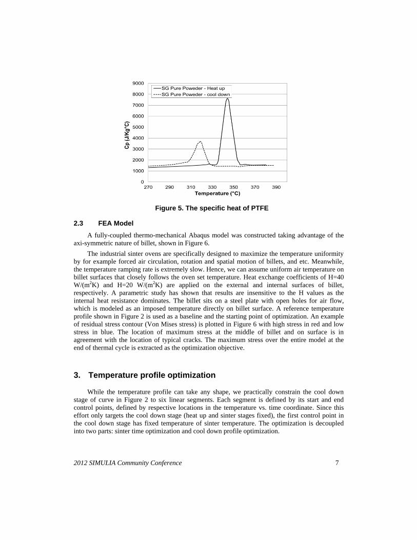
The specific heat was measured by DSC in house, plotted in Figure 5. Together with the
volume change data, we can determinate that the specific PTFE powder starts to sinter at above
355℃ and crystallizes between 298℃ and 320℃.
Figure 4. Pseudo-thermal expansion coeff. in billet axial and radial directions
2012 SIMULIA Community Conference 7
2.3 FEA Model
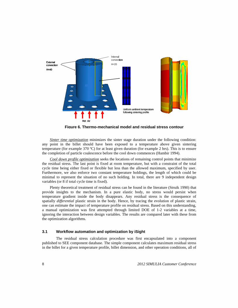
A fully-coupled thermo-mechanical Abaqus model was constructed taking advantage of the
axi-symmetric nature of billet, shown in Figure 6.
The industrial sinter ovens are specifically designed to maximize the temperature uniformity
by for example forced air circulation, rotation and spatial motion of billets, and etc. Meanwhile,
the temperature ramping rate is extremely slow. Hence, we can assume uniform air temperature on
billet surfaces that closely follows the oven set temperature. Heat exchange coefficients of H=40
W/(m2K) and H=20 W/(m2K) are applied on the external and internal surfaces of billet,
respectively. A parametric study has shown that results are insensitive to the H values as the
internal heat resistance dominates. The billet sits on a steel plate with open holes for air flow,
which is modeled as an imposed temperature directly on billet surface. A reference temperature
profile shown in Figure 2 is used as a baseline and the starting point of optimization. An example
of residual stress contour (Von Mises stress) is plotted in Figure 6 with high stress in red and low
stress in blue. The location of maximum stress at the middle of billet and on surface is in
agreement with the location of typical cracks. The maximum stress over the entire model at the
end of thermal cycle is extracted as the optimization objective.
3. Temperature profile optimization
While the temperature profile can take any shape, we practically constrain the cool down
stage of curve in Figure 2 to six linear segments. Each segment is defined by its start and end
control points, defined by respective locations in the temperature vs. time coordinate. Since this
effort only targets the cool down stage (heat up and sinter stages fixed), the first control point in
the cool down stage has fixed temperature of sinter temperature. The optimization is decoupled
into two parts: sinter time optimization and cool down profile optimization.
Figure 5. The specific heat of PTFE
8 2012 SIMULIA Customer Conference
Sinter time optimization minimizes the sinter stage duration under the following condition:
any point in the billet should have been exposed to a temperature above given sintering
temperature (for example 370 ºC) for at least given duration (for example 2 hrs). This is to ensure
the completion of particle coalescence before the cool down commences (Hambir 1994).
Cool down profile optimization seeks the locations of remaining control points that minimize
the residual stress. The last point is fixed at room temperature, but with a constraint of the total
cycle time being either fixed or flexible but less than the allowed maximum, specified by user.
Furthermore, we also enforce two constant temperature holdings, the length of which could be
minimal to represent the situation of no such holding. In total, there are 9 independent design
variables (or 8 if total cycle time is fixed).
Plenty theoretical treatment of residual stress can be found in the literature (Struik 1990) that
provide insights to the mechanism. In a pure elastic body, no stress would persist when
temperature gradient inside the body disappears. Any residual stress is the consequence of
spatially differential plastic strain in the body. Hence, by tracing the evolution of plastic strain,
one can estimate the impact of temperature profile on residual stress. Based on this understanding,
a manual optimization was first attempted through limited DOE of 1-2 variables at a time,
ignoring the interaction between design variables. The results are compared later with these from
the optimization algorithms.
3.1 Workflow automation and optimization by iSight
The residual stress calculation procedure was first encapsulated into a component
published to SEE component database. The simple component calculates maximum residual stress
in the billet for a given temperature profile, billet dimension, and other operation conditions, all of
Figure 6. Thermo-mechanical model and residual stress contour
Hot Air
External convection
H=40
Internal
convection
H=20
Uniform ambient temperature following sintering profile
Hot Air
External convection
H=40
Internal
convection
H=20
Hot Air
External convection
H=40
Internal
convection
H=20
Uniform ambient temperature following sintering profile

2012 SIMULIA Community Conference 9
which are exposed as the component’s input and output parameters. The modular structure ensures
the continued refinement of FEA model can be conducted without influencing the optimization
workflow. Logic was built into the component to skip the actual Abaqus execution if the
temperature profile is not valid (for example not monotonically increasing or decreasing) to save
unnecessary computation. The execution time for the component is typically 5-10 minutes.
The complete optimization workflow is shown in Figure 7, which is composed of the
following blocks as labeled in the figure: A) The inputs are first read from an Excel file, which
end users fill in as a request. The key inputs include a reference temperature profile, billet
dimensions, sintering condition (sinter temperature, sinter time). Also as inputs are parameters for
optimization algorithms: the maximum cycle time, whether to minimize residual stress only for
the given cycle time, or both residual stress and total cycle time with specified relative weights; B).
The residual stress from the reference temperature profile is first calculated; C). the actual
optimization is carried out, which will be discussed below; and D). the optimized profile and
minimized residual stress are saved in an Excel file and emailed to the end users automatically.
The optimization workflow consists of two optimizations components, labeled as C-1 and
C-2 respectively in Figure 7:
C-1 -- sinter time optimization: The design variable is the time coordinate of the first control
point in the cool down stage (Figure 2), the minimization of which is also the objective function.
The minimal temperature was obtained (as an output of residual stress calculation component) at a
specified time (sinter time) before this time coordinate, which is constrained to be above a
specified temperature (sinter temperature). The gradient based MMFD algorithm is used for this
simple problem, which typically converges in less than 10-20 iterations.
C-2 – cool down profile optimization: The multi-variable, multi-objective, and highly non-linear
optimization contains 9 design variables of the temperature-time coordinates of control points in
Figure 2’s cool down stage. Only monotonically decreasing temperature vs. time is meaningful,
and should be a constraint. In constrained optimization, however, the infeasible design points are
still evaluated only with high penalty – which results in enormous wasted iterations. Henceforth,
the increments in temperature and time between these control points are taken as the design
variables instead, naturally enforcing the monotonic condition. Consequently, the only constraint
remains as the time coordinate of the last control point should be less than the maximum allowed
value. The optimization component has the option of turning on/off individual constraint/objective
based on Boolean parameter. The feature is utilized to switch the optimization workflow tween
single objective – residual stress, and two objectives – residual stress and cycle time. In the latter
case, the relative weights of the two objectives are exposed as inputs specified by user (for
example, 1 hour cycle time ~ 0.1 MPa residual stress).
The complexity of the problem is not suitable for any gradient based optimization
algorithms, esp. the likelihood of numerous local minimal; and the relatively long evaluation time
of each design point precludes the usage of genetic algorithm based methods. The effectiveness of
four exploratory direct methods type of algorithms is compared: Evol, DownhillSimplex, Hooke-
Jeeves, and Pointer. The DownhillSimplex was found to achieve the best balance between the
convergence speed and ability of escaping local minimal.
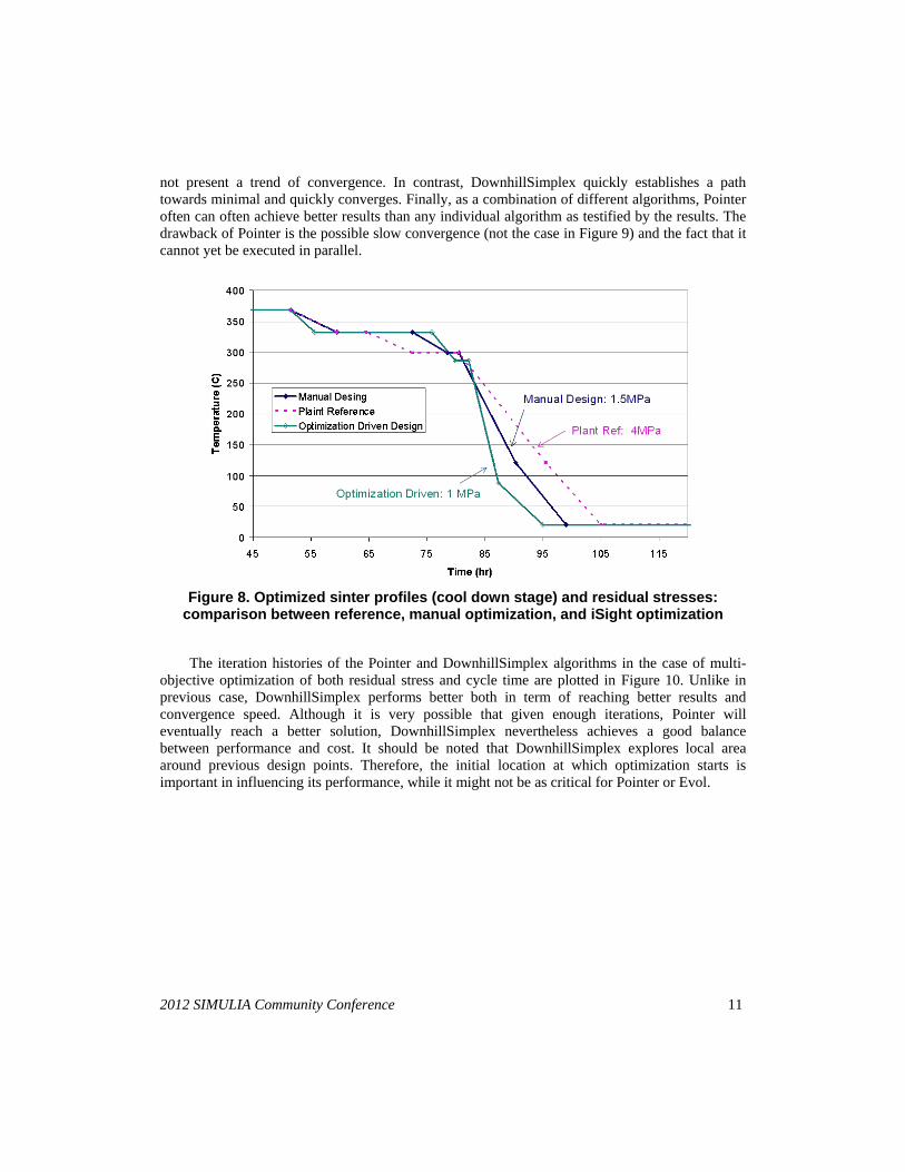
An example of optimization results is shown in Figure 8. In the plot, the cool down stage
of the reference profile, the result from manual optimization, and the result from iSight
optimization are compared, together with their respective residual stresses. While the (costly)

10 2012 SIMULIA Customer Conference
manual optimization delivered improvement from the reference profile, the iSight optimization
algorithms arrived at a significantly better solution with little cost. Both the manual and iSight
optimizations realized that better solution could be achieved from reducing the duration of post-
crystallization temperature holding while increasing the duration of pre-crystallization temperature
holding.
3.2 Effectiveness of optimization algorithms
The Direct Method category of optimization algorithms is well suitable for the problem under
discussion. Such algorithm evaluates only the value at sample points but not the gradient, and
follows the improved path of performance index. While the reaching of global minimal is by no
means ensured, the likelihood of being trapped in local minimum gets dramatically reduced
compared with gradient based methods. Other algorithms available in iSight are not suitable for
the current problem either because of the complexity (for gradient based) or the relatively long
evaluation time (for genetic algorithm based).
Four different exploratory algorithms - Evol, DownhillSimplex, Hooke-Jeeves, and Pointer -
were evaluated in their effectiveness in the multi-variable multi-objective optimization of cool
down stage, esp. per the convergence speed and ability of escaping local minimal.
The iteration histories of the four algorithms in the case of fixed total cycle time (97 hrs)
single objective function (residual stress) are plotted in Figure 9, showing dramatically different
behaviors. Hooke-Jeeves is easily trapped in local minimal, and has difficulty in progressing into
correct direction. Evol, being an evolution algorithm, explores widely in the design space and does
Figure 7. Optimization workflow overview
A B C D
C-1 C-2
2012 SIMULIA Community Conference 11
not present a trend of convergence. In contrast, DownhillSimplex quickly establishes a path
towards minimal and quickly converges. Finally, as a combination of different algorithms, Pointer
often can often achieve better results than any individual algorithm as testified by the results. The
drawback of Pointer is the possible slow convergence (not the case in Figure 9) and the fact that it
cannot yet be executed in parallel.
Figure 8. Optimized sinter profiles (cool down stage) and residual stresses: comparison between reference, manual optimization, and iSight optimization
The iteration histories of the Pointer and DownhillSimplex algorithms in the case of multi-
objective optimization of both residual stress and cycle time are plotted in Figure 10. Unlike in
previous case, DownhillSimplex performs better both in term of reaching better results and
convergence speed. Although it is very possible that given enough iterations, Pointer will
eventually reach a better solution, DownhillSimplex nevertheless achieves a good balance
between performance and cost. It should be noted that DownhillSimplex explores local area
around previous design points. Therefore, the initial location at which optimization starts is
important in influencing its performance, while it might not be as critical for Pointer or Evol.

12 2012 SIMULIA Customer Conference
a). Evol: 1.55 MPa b). Hooke-Jeeves: 1.95 MPa
c). Pointer: 1.59MPa d). DownhillSimplex: 1.68MPa
Figure 9. Iteration history of different algorithms and residual stress achieved for single objective optimization with fixed cycle time
3.3 Low operation cost and high availability
As we have elaborated previously, the barriers to the wide implementation of simulation are
the operation cost and availability; where the availability could mean both access from any
geographic locations and at any time on demand.
We have seen that the iSight has helped to dramatically reduce the development cost of
simulation workflow and operation cost in the use of which. The knowledge of analysts is
captured in the encapsulated workflow and custom component.
The deployment of SEE platform and WebTop addressed the availability issue, especially for
businesses whose engineering teams are not centrally located, or do not have sufficient dedicated
FEA analysts resources. The WebTop presents any iSight component published to SEE
component database to webpage interface that can be executed through standard internet browser.

2012 SIMULIA Community Conference 13
The ability of maintaining and hosting simulation in a central location, accessible through the web
browser sidestepped the cost of software deployment, maintenance, and user training.
a). Pointer: best objective function = 2.5 (Stress=1.5MPa, Cycle time=88 hrs)
b). DownhillSimplex: best objective function = 2.2 (Stress=1.1MPa, Cycle time=97 hrs)
Figure 10. Iteration history comparison between Pointer and DownhillSimplex in multi-objective optimization
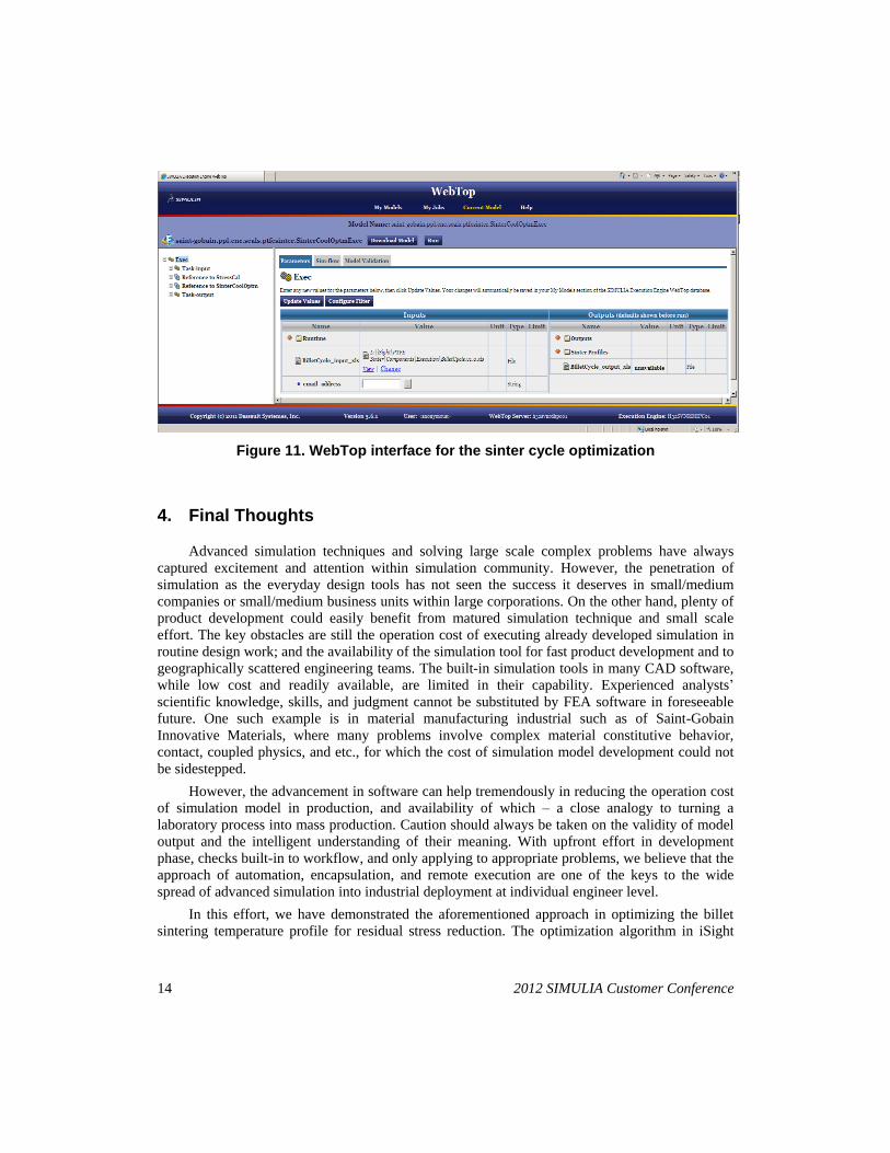
In this case, the sinter profile optimization workflow was published as a WebTop application,
hosted in corporate central R&D’s computation resource. The WebTop interface seen by end user
in a browser is shown in Figure 11. End users, through the corporate intranet, download the
template Excel file to fill in request, which is uploaded in the same webpage as the input file for
the optimization component, and the job is submitted to the central server. The optimization
results are automatically emailed to the user upon finish.
14 2012 SIMULIA Customer Conference
Figure 11. WebTop interface for the sinter cycle optimization
4. Final Thoughts
Advanced simulation techniques and solving large scale complex problems have always
captured excitement and attention within simulation community. However, the penetration of
simulation as the everyday design tools has not seen the success it deserves in small/medium
companies or small/medium business units within large corporations. On the other hand, plenty of
product development could easily benefit from matured simulation technique and small scale
effort. The key obstacles are still the operation cost of executing already developed simulation in
routine design work; and the availability of the simulation tool for fast product development and to
geographically scattered engineering teams. The built-in simulation tools in many CAD software,
while low cost and readily available, are limited in their capability. Experienced analysts’
scientific knowledge, skills, and judgment cannot be substituted by FEA software in foreseeable
future. One such example is in material manufacturing industrial such as of Saint-Gobain
Innovative Materials, where many problems involve complex material constitutive behavior,
contact, coupled physics, and etc., for which the cost of simulation model development could not
be sidestepped.
However, the advancement in software can help tremendously in reducing the operation cost
of simulation model in production, and availability of which – a close analogy to turning a
laboratory process into mass production. Caution should always be taken on the validity of model
output and the intelligent understanding of their meaning. With upfront effort in development
phase, checks built-in to workflow, and only applying to appropriate problems, we believe that the
approach of automation, encapsulation, and remote execution are one of the keys to the wide
spread of advanced simulation into industrial deployment at individual engineer level.
In this effort, we have demonstrated the aforementioned approach in optimizing the billet
sintering temperature profile for residual stress reduction. The optimization algorithm in iSight
2012 SIMULIA Community Conference 15
drives an Abaqus workflow that calculates post sintering residual stress of PTFE billet for a given
temperature profile. The optimization and simulation workflow are entirely automated and
encapsulated into iSight components published to SEE, with simple Excel file as the input/output
interfaces. The workflow is then published by WebTop to intranet, and allows remote execution
from anywhere and anytime. Within the predefined design scope, an engineer can conduct a
temperature profile optimization for specific application without incurring any cost other than
computer run time.
References
1. Drobny, J. G., “Technology of Fluoropolymers”, CRC Press, 2009, pp. 58-72.
2. Ebnesajjad, S., “Fabrication and Processing of Granular Polytetrafluoroethylene”, in
Fluoroplastics: the Definitive User’s Guide and DataBook, vol. 1, Plastic Design Library,
2000, pp 90-107.
3. Narkis, M., “Sintering of Compacted Thermoplastic Powders”, Polymer Powder Technology,
1995, pp. 279-298
4. Mazur, S., “Coalescence of Polymer Particles”, Polymer Powder Technology, 1995, pp. 157-
214
5. Skorokhod, V. V., “On the Phenomenological Theory of Densification for the Sintering of
Porous bodies”, Poroshk. Metall., 1[2], 1961, pp.14-23
6. Lin, Y. Y.; Hui, C. Y.; Jagota, A, ”The Role of Viscoelastic Adhesive Contact in the Sintering
of Polymeric Particles”, Journal of Colloid and Interface Science, 237, 2001, pp. 267-282
7. Radhakrishnan, S.; Nakarni, V. M., “Modification of Crystallinity and Structure in Powder
Processing of Polytetra Fluoroethylene”, Int. Journal of Polymeric Materials, 11, 1986, pp.
79-94
8. Andena, L.; Rink, M., “Simulation of PTFE Sintering: Thermal Stresses and Deformation
Behavior”, Polymer Engineering and Science, 44(7), 2004, pp. 1368-1378
9. Struik, L. C., “Internal Stresses, Dimensional Stability, and Molecular Orientation in
Plastics”, John Wiley & Son, 1990
10. Hambir, S. S.; Nadkarni, V. M., “Strength Development in Powder Processing of
Poly(tetrafluoroethylene)”, Polymer Engineering and Science, 34(13), 1994, pp. 1065-1069
11. Bergstrom J. S.; Hillbert, Jr L. B., “A Constitutive Model for Predicting the Large
Deformation Thermomechanical Behavior of Fluoropolymers”, Mechanics of Materials, 37,
2005, p. 899-913
Acknowledgment
The authors would like to express the appreciation for the support from Saint-Gobain
Northboro R&D Center, Saint-Gobain Research Shanghai, and Saint-Gobain Performance
Plastics. The effort would not be possible without the valuable discussion with and experimental
support from colleagues at Saint-Gobain R&D Centers.
Related Documents