i Automated generic parameterized design of aircraft fairing and windshield Vijaykumar Govindharajan Aakash Narender Singh LIU-IEI-TEK-A-12/01271-SE Department of Management and Engineering Division of Flumes Department of Management and Engineering SE-581 83 Linköping, Sweden

Welcome message from author
This document is posted to help you gain knowledge. Please leave a comment to let me know what you think about it! Share it to your friends and learn new things together.
Transcript
i
Automated generic parameterized design of
aircraft fairing and windshield
Vijaykumar Govindharajan
Aakash Narender Singh
LIU-IEI-TEK-A-12/01271-SE
Department of Management and Engineering
Division of Flumes
Department of Management and Engineering
SE-581 83 Linköping, Sweden

ii

iii
Upphovsrätt
Detta dokument hålls tillgängligt på Internet – eller dess framtida ersättare – under 25 år från publiceringsdatum under förutsättning att inga extraordinära omständigheter uppstår. Tillgång till dokumentet innebär tillstånd för var och en att läsa, ladda ner, skriva ut enstaka kopior för enskilt bruk och att använda det oförändrat för ickekommersiell forskning och för undervisning. Överföring av upphovsrätten vid en senare tidpunkt kan inte upphäva detta tillstånd. All annan användning av dokumentet kräver upphovsmannens medgivande. För att garantera äktheten, säkerheten och tillgängligheten finns lösningar av teknisk och administrativ art. Upphovsmannens ideella rätt innefattar rätt att bli nämnd som upphovsman i den omfattning som god sed kräver vid användning av dokumentet på ovan beskrivna sätt samt skydd mot att dokumentet ändras eller presenteras i sådan form eller i sådant sammanhang som är kränkande för upphovsmannens litterära eller konstnärliga anseende eller egenart. För ytterligare information om Linköping University Electronic Press se förlagets hemsida http://www.ep.liu.se/.
Copyright The publishers will keep this document online on the Internet – or its possible replacement – for a period of 25 years starting from the date of publication barring exceptional circumstances. The online availability of the document implies permanent permission for anyone to read, to download, or to print out single copies for his/her own use and to use it unchanged for non-commercial research and educational purpose. Subsequent transfers of copyright cannot revoke this permission. All other uses of the document are conditional upon the consent of the copyright owner. The publisher has taken technical and administrative measures to assure authenticity, security and accessibility. According to intellectual property law the author has the right to be mentioned when his/her work is accessed as described above and to be protected against infringement. For additional information about Linköping University Electronic Press and
its procedures for publication and for assurance of document integrity, please refer to its
www home page: http://www.ep.liu.se/.
©Vijaykumar Govindharajan & Aakash Narender Singh

iv
v
Automated generic parameterized design of
aircraft fairing and windshield
Vijaykumar Govindharajan
Aakash Narender Singh
LIU-IEI-TEK-A-12/01271-SE
Supervisor
Raghu Chaitanya M V
PhD – Linköping University
Co-Supervisor
Patrick Berry
Lecturer, Linköping University
Examiner
Christopher Jouannet
Assistant Professor, Linköping University

vi
Abbreviation CATIA Computer Aided Three Dimensional Interactive Application
VBA Visual Basic for Application
KP Knowledge Pattern
ECS Environmental control systems
UDF User Defined Feature
CP Centre Point
SPE Star Pilot Eye
MVP Minimum Visibility Pattern
PC Power-copy
AWACS Airborne Warning and Control Systems
AEW&C Airborne Early Warning and Control
vii
Abstract
The process of design is time consuming and result oriented. There is
always a better scope for any design that reduces the time with better precision.
Considering this as a major factor during design process, two of the vital parts of the
aircraft conceptual design are taken into account where a lot of time can be saved. Major
components considered in this work are fairings for the lift generating surfaces and
cockpit windshield. In this work the major inference is to reduce the time spent on the
initial conceptual design.
The two components designed in this work are fairings and windshield. The
fairing design in this work provides a flexible template which can be used for various
fuselage and wing configurations for transport aircrafts. The windshield is classified into
two types in this work, flat and blend windshield. Both the type of windshields can be
implemented on appropriate fuselage.
Both the components are designed to be implemented in single pilot as well
as double pilot aircrafts. They also have parameters which can be modified according to
the user requirement. The changes in the parameters provide the change in shape, size
and volume of the components.
The software used for this is CATIA V5. The process is carried out using two
automation methods available in CATIA namely Power-Copy and Knowledge pattern. A
comparison between the effectiveness of two automation methods used in this work is
performed.

viii
Acknowledgement
The master thesis work was carried out in Department of Management and
Engineering, Division of Flumes at Linköping University, Sweden. It was a pleasure
working with everyone in the department. There is a great gratitude and respect for
everyone who has helped the authors to complete the work in a successful manner. We
are glad for using this opportunity to thank everyone who helped directly or indirectly
in the completion of the work successfully.
Special thanks to Patrick Berry and Raghu Chaitanya.M.V who have been
constantly motivating and suggesting improvements. We wish to extend our gratitude to
Christopher Jouannet, Tomas Melin, Mehdi Tarkian and Kristian Amadori. The feedback
and suggestions from everyone mentioned above has been very vital and valuable to
judge the progress of the work.
Family and friend are all the driving force and ultimate motivation factor
for us. Thanking them would not be enough to express our gratefulness.
Vijaykumar Govindharajan
Aakash Narender Singh
Linköping

ix

x
Contents
ABBREVIATION ................................................................................................................................ VI
ABSTRACT ........................................................................................................................................ VII
ACKNOWLEDGEMENT ................................................................................................................ VIII
CONTENTS ........................................................................................................................................... X
TABLE OF FIGURES ........................................................................................................................ XII
LIST OF TABLES ............................................................................................................................ XIII
CHAPTER 1 - INTRODUCTION ....................................................................................................... 1
1.1 FAIRINGS ........................................................................................................................................................ 2 1.2 WINDSHIELD ................................................................................................................................................. 2
CHAPTER 2 - THEORY ...................................................................................................................... 4
2.1 FAIRING .......................................................................................................................................................... 4 2.2 DESIGN CONSIDERATIONS FOR WINDSHIELD ............................................................................................ 4 2.3 FAR PILOT COMPARTMENT VIEW. ............................................................................................................. 4 2.4 VISIBILITY REQUIREMENT .......................................................................................................................... 4 2.5 POSITIONING OF THE PILOT ......................................................................................................................... 7 2.6 COMPUTER AIDED DESIGN (CAD) ............................................................................................................ 8
2.6.1 Power-copy ........................................................................................................................................... 9 2.6.2 Knowledge pattern scripting ....................................................................................................... 10
CHAPTER 3 - CAD METHOD ........................................................................................................ 14
3.1 DEVELOPMENT OF WINDSHIELD .............................................................................................................. 14 3.2 Windshield automation framework ............................................................................................. 15 3.3 Flat panel windshield ......................................................................................................................... 15
3.3.1 Basic Flat Surface Template ............................................................................................................. 15 3.3.2 Visibility Template ............................................................................................................................... 17 3.3.3 Windows and struts ............................................................................................................................ 20 3.3.4 Fuselage Blend Template .................................................................................................................. 21
3.4 Blend panel windshield...................................................................................................................... 22 3.4.1 Visibility Pattern ................................................................................................................................... 22 3.4.2 Strut ........................................................................................................................................................... 24 3.4.3 Windows .................................................................................................................................................. 25
3.5 Global Parameters for windshield ................................................................................................ 25 3.6 DEVELOPMENT OF FAIRINGS .................................................................................................................... 27
3.7 Fairing automation framework ..................................................................................................... 27 3.8 Fairing ...................................................................................................................................................... 28
3.8.1 Low fairing template ........................................................................................................................... 28 3.8.2 Mid fairing template ............................................................................................................................ 30 3.8.3 High fairing template .......................................................................................................................... 31

xi
3.8.4 Horizontal tail fairing template ...................................................................................................... 33 3.8.5 Vertical tail fairing template ............................................................................................................ 35
CHAPTER 4 - RESULTS .................................................................................................................. 38
4.1 COMPARISON OF WINDSHIELD PANELS: ................................................................................................. 39 4.1.1 Blend panel windshield .................................................................................................................. 39 4.1.2 Flat panel windshield ..................................................................................................................... 42
4.2 COMPARISON OF FAIRINGS ....................................................................................................................... 44 4.3 TIME COMPARISON ................................................................................................................................... 51
4.3.1 Flat panel ............................................................................................................................................. 51 4.3.2 Blend panel ......................................................................................................................................... 52 4.3.3 Fairing ................................................................................................................................................... 53
CHAPTER 5 - CONCLUSION AND FUTURE WORKS .............................................................. 56
5.1 CONCLUSION ............................................................................................................................................... 56 5.2 FUTURE WORK ........................................................................................................................................... 57
5.2.1 Flow Automation and optimization ......................................................................................... 57 5.2.2 Optimization of windshield .......................................................................................................... 57 5.2.3 Fairing for Pylon, External Radar, AEWS, AWACS ............................................................. 57
REFERENCES .................................................................................................................................... 59
APPENDIX ......................................................................................................................................... 60
A - APPENDIX - KP SCRIPT FOR PANELS ....................................................................................................... 60 B- APPENDIX - VB ............................................................................................................................................ 74
B.1 Fairng-VB-1 ............................................................................................................................................ 74 B.2 Fairing-VB-2 .......................................................................................................................................... 76 B.3 Fairing-VB-3 .......................................................................................................................................... 77
C- APPENDIX C – KNOWLEDGE PATTERN ..................................................................................................... 80 C.1 MainFairng-KP ...................................................................................................................................... 80 C.2 Horizontal Tail – KP ........................................................................................................................... 81 C.3 Vertical Tail – KP ................................................................................................................................. 82
xii
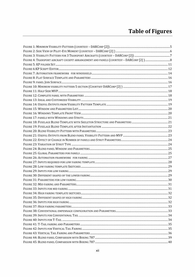
Table of Figures
FIGURE 1: MINIMUM VISIBILITY PATTERN (COURTESY – DARCORP [2]) .......................................................................................... 5 FIGURE 2: SIDE VIEW OF PILOT-EYE MOMENT (COURTESY – DARCORP [2] ) ................................................................................. 6 FIGURE 3: VISIBILITY PATTERN FOR 3 TRANSPORT AIRCRAFTS (COURTESY – DARCORP [2]) ..................................................... 7 FIGURE 4: TRANSPORT AIRCRAFT COCKPIT ARRANGEMENT AND PANELS (COURTESY – DARCORP [2] ) ..................................... 8 FIGURE 5: KP FOLDER SET ........................................................................................................................................................................ 11 FIGURE 6:KP SCRIPT EDITOR ................................................................................................................................................................... 12 FIGURE 7: AUTOMATION FRAMEWORK FOR WINDSHIELD .................................................................................................................. 14 FIGURE 8: FLAT SURFACE TEMPLATE AND PARAMETERS ................................................................................................................... 16 FIGURE 9: PANEL JOIN SURFACE ............................................................................................................................................................... 16 FIGURE 10: MINIMUM VISIBILITY PATTERN 5 SECTION (COURTSEY DARCORP [2] ) ................................................................... 17 FIGURE 11: HALF SIDE MVP .................................................................................................................................................................... 18 FIGURE 12: COMPLETE PANEL WITH PARAMETERS ............................................................................................................................. 18 FIGURE 13: IDEAL AND CUSTOMIZED VISIBILITY .................................................................................................................................. 19 FIGURE 14: USEFUL OUTPUTS FROM VISIBILITY PATTERN TEMPLATE ............................................................................................ 19 FIGURE 15: WINDOW AND PARAMETERS LIST ...................................................................................................................................... 20 FIGURE 16: WINDOWS TEMPLATE FRONT VIEW .................................................................................................................................. 20 FIGURE 17: PANELS WITH WINDOWS AND STRUTS .............................................................................................................................. 21 FIGURE 18: FUSELAGE BLEND TEMPLATE WITH SKELETON STRUCTURE AND PARAMETERS ...................................................... 21 FIGURE 19: FUSELAGE BLEND TEMPLATE AFTER INSTANTIATION ................................................................................................... 22 FIGURE 20: BLEND VISIBILITY PATTERN WITH PARAMETERS ........................................................................................................... 23 FIGURE 21: USEFUL OUTPUTS FROM BLEND PANEL VISIBILITY PATTERN AND MVP ................................................................... 23 FIGURE 22: EFFECT OF CHANGE IN NUMBER OF PANELS AND STRUT PARAMETERS ...................................................................... 24 FIGURE 23: VARIATION OF STRUT TYPE ................................................................................................................................................ 24 FIGURE 24: BLEND PANEL WINDOW AND PARAMETERS ..................................................................................................................... 25 FIGURE 25: GLOBAL PARAMETERS FOR PANELS ................................................................................................................................... 25 FIGURE 26: AUTOMATION FRAMEWORK FOR FAIRING ....................................................................................................................... 27 FIGURE 27: INPUTS REQUIRED FOR LOW FAIRING TEMPLATE ............................................................................................................. 28 FIGURE 28: LOW FAIRING TEMPLATE SKETCHES .................................................................................................................................. 29 FIGURE 29: INPUTS FOR LOW FAIRING .................................................................................................................................................... 29 FIGURE 30: DIFFERENT SHAPES OF THE LOWER FAIRING .................................................................................................................... 29 FIGURE 31: PARAMETERS FOR LOW FAIRING ......................................................................................................................................... 30 FIGURE 32: MID FAIRING AND PARAMETERS......................................................................................................................................... 31 FIGURE 33: INPUTS FOR MID FAIRING ..................................................................................................................................................... 31 FIGURE 34: HIGH FAIRING TEMPLATE SKETCHES .................................................................................................................................. 32 FIGURE 35: DIFFERENT SHAPES OF HIGH FAIRING ................................................................................................................................ 32 FIGURE 36: INPUTS FOR HIGH FAIRING ................................................................................................................................................... 32 FIGURE 37: HIGH FAIRING PARAMETERS ................................................................................................................................................ 33 FIGURE 38: CONVENTIONAL EMPENNAGE CONFIGURATION AND PARAMETERS .............................................................................. 33 FIGURE 39: INPUTS FOR CONVENTIONAL TAIL ..................................................................................................................................... 34 FIGURE 40: INPUTS FOR T-TAIL .............................................................................................................................................................. 34 FIGURE 41: T-TAIL FAIRING AND PARAMETERS ................................................................................................................................... 35 FIGURE 42: INPUTS FOR VERTICAL TAIL FAIRING ................................................................................................................................ 35 FIGURE 43: VERTICAL TAIL FAIRING AND PARAMETERS .................................................................................................................... 36 FIGURE 44: BLEND PANEL COMPARISON WITH BOEING 787 ............................................................................................................. 39 FIGURE 45: BLEND PANEL COMPARISON WITH BOEING 787 ............................................................................................................. 40

xiii
FIGURE 46: BLEND PANEL COMPARISON WITH BOEING 787 ............................................................................................................. 40 FIGURE 47: BLEND PANEL COMPARISON WITH BOEING 787 ............................................................................................................. 41 FIGURE 48: FLAT PANEL COMPARISON WITH AIRBUS A380 ............................................................................................................. 42 FIGURE 49: FLAT PANEL COMPARISON WITH AIRBUS A380 ............................................................................................................. 42 FIGURE 50: FLAT PANEL COMPARISON WITH AIRBUS A380 ............................................................................................................. 43 FIGURE 51: MAIN WING FAIRING VISUAL COMPARISON OF A380 ...................................................................................................... 44 FIGURE 52: MAIN WING FAIRING VISUAL COMPARISON OF A380 ..................................................................................................... 44 FIGURE 53: MAIN WING FAIRING VISUAL COMPARISON OF BOEING 787 ......................................................................................... 45 FIGURE 54: MAIN WING FAIRING VISUAL COMPARISON OF A380 ..................................................................................................... 45 FIGURE 55: DIFFERENT SHAPES OF LOW WING FAIRING ...................................................................................................................... 46 FIGURE 56: ANTONOV 148 HIGH WING AIRCRAFT MAIN FAIRING ..................................................................................................... 46 FIGURE 57: ANTONOV 148 HIGH WING AIRCRAFT MAIN FAIRING ..................................................................................................... 46 FIGURE 58: DIFFERENT SHAPES OF HIGH WING FAIRING ..................................................................................................................... 46 FIGURE 59: FARING FOR DIFFERENT SHAPES OF FUSELAGE ................................................................................................................ 47 FIGURE 60: COMPARISON OF BOEING 787 VERTICAL TAIL FAIRING ................................................................................................. 47 FIGURE 61: COMPARISON OF AIRBUS A380 VERTICAL TAIL FAIRING .............................................................................................. 48 FIGURE 62: MOST COMMONLY USED VERTICAL FAIRING ..................................................................................................................... 48 FIGURE 63: T-TAIL CONFIGURATION ...................................................................................................................................................... 48 FIGURE 64: FOUR VIEW OF T-TAIL CONFIGURATION ............................................................................................................................ 49 FIGURE 65 : CESSNA CITATION C12 T-TAIL ......................................................................................................................................... 49 FIGURE 66 : ILLUSION 69 T-TAIL ............................................................................................................................................................ 49 FIGURE 67 : TUPOLEVE 154 T-TAIL ........................................................................................................................................................ 49 FIGURE 68: TIME COMPARISON FOR FLAT PANEL KP AND PC INSTANTIATION ............................................................................... 51 FIGURE 69: TIME COMPARISON FOR FLAT PANEL KP AND PC DELETION ......................................................................................... 52 FIGURE 70: AVERAGE TIME COMPARISON FOR FAIRING INSTANTIATION BY KP AND PC ............................................................... 52 FIGURE 71: OBSERVATIONS FOR FAIRING INSTANTIATION .................................................................................................................. 53 FIGURE 72: OBSERVATIONS FOR FAIRING DELETION ............................................................................................................................ 54
List of tables
TABLE 1: TIME TAKEN FOR FLAT PANEL INSTANTIATION ............................................................................................ 51 TABLE 2: TIME TAKEN FOR BLEND PANEL INSTANTIATION ......................................................................................... 52 TABLE 3: OBSERVATIONS FOR FAIRING INSTANTIATION .............................................................................................. 53 TABLE 4: FAIRING TIME OBSERVATION FOR DELETING ................................................................................................ 54

1
Chapter 1 - Introduction
Fairings are a very important part in the design phase of an aircraft. There
are various aerodynamic as well as weight factors to be considered while designing the
fairings. This work provides the user with a basic surface of the fairing which can be
used for any combination of fuselage and wing.
Mostly the fairings are components which help in reducing the interference
drag at the junction of any surfaces [7], [8]. In this work the design of fairing is also
associated with design of pod or bay for low wing and high wing configurations. In most
of the low wing aircrafts today, the pod or the bay provides room for certain
components like the landing gear, ECS, and various outlet points. Such requirements are
possible in this work by changing the parameters which defines the shape and size.
The windshield is also a very important component which defines the
shape of the forward fuselage. The windshields are created based on the minimum
visibility requirement according to the FAR [14]. This work provides a framework for
the user to start working on the windshield and reduce the time spent during early
design stages. In this work the fuselage is modified to some extent around the
windshield to make sure the results have smooth fuselage after windshield is placed in
its position. There are parameters to control the smoothness of the fuselage.
The Automation of fairings and windshield panels is achieved with two of
the automation methods available in CATIA, Knowledge Pattern (KP) and Power-copy
(PC). Comparison is done between both the methods to analyze which one is better.
Since the availability of the design details of existing aircrafts is private data for
respective companies, the validation of the design achieved and flexibility of the models
is shown by trying to compare the work with the designs of some existing aircrafts.

2
1.1 Fairings
The main aim of this work is to reduce the initial time spent in the design of
fairings for any aircraft. For any designer the need for a wing root fairing depends on
what type of aerodynamic advantage is needed and depends on the type of components
to be placed inside the fairings [10, 13]. The fairing design also changes according to the
configuration of the wing (Low, mid or high). In-order to achieve the initial reduction in
time for the creation of fairings automating the work is a very feasible solution as
discussed earlier. For automation of a component in CATIA it is convenient to create a
template or a UDF which can take the required shapes according to the input. The main
reason for generating an automated design for the fairings is to ensure the time spent on
initial design is reduced and the desired results are obtained with lesser effort.
1.2 Windshield
The development of the windshield on the aircraft in CAD is also to reduce
the man hours involved from design to manufacturing of the panels. Since in a
conceptual stage the very basic sense of panel designs are to be developed and give a
quick lead in designing. The basic visibility requirements for the pilot are to be met and
have to be flexible enough to change the number of windows on the panels, shapes of the
panels and should fit in with various cockpits.

3
4
Chapter 2 - Theory
2.1 Fairing
Wing fairing is a fillet introduced between fuselage and the wing root to
reduce the interference drag. The amount of fillet required sometimes is defined by the
ratio of the Chord or it can be arbitrary based on some flow analysis or wind tunnel
experiments. To achieve these criteria it is also important that more emphasis is done
towards the flexibility such that the design can meet any type of changes required in the
shape of the fairing. More importantly the design is also capable of taking the shape of
nearly all existing fairings in different aircrafts. This work gives the designer an initial
heads up start in the conceptual design stage.
2.2 Design considerations for windshield
Design of any part in any product is based on certain limitations and
requirements. Similarly for the design of a cockpit panel the major consideration is the
visibility pattern provided by FAR [14]. The visibility pattern should satisfy the
following requirements for both civil and military aircrafts.
1. The pilot should have a good visibility of the surroundings during Takeoff and
Landing.
2. The pilot must be able to observe conflicting traffic during en-route operations.
2.3 FAR Pilot compartment view.
Each pilot compartment must be
(1) Arranged with sufficiently extensive, clear and undistorted view to
enable the pilot to safely taxi, takeoff, approach, land, and perform any maneuvers
within the operating limitations of the airplane.
(2) Free from glare and reflections that could interfere with the pilot's
vision. Compliance must be shown in all operations for which certification is requested
(3) Designed so that moderate rain conditions do not unduly impair the
pilot's view of the flight path in normal flight and while landing.
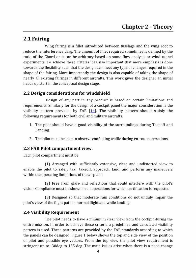
2.4 Visibility Requirement
The pilot needs to have a minimum clear view from the cockpit during the
entire mission. In order to achieve these criteria a predefined and calculated visibility
pattern is used. These patterns are provided by the FAR standards according to which
the panels can be designed. Figure 1 below shows the top and side view of the position
of pilot and possible eye vectors. From the top view the pilot view requirement is
stringent up to -30deg to 135 deg. The main issues arise when there is a need change

5
from single pilot to double pilot. This is comparatively challenging as the position of the
pilots change and so as the visibility angles on the horizontal plane. Similarly the picture
also shows the side view positioning of the pilot eye.
Figure 1: Minimum Visibility Pattern (courtesy – DARCorp [2])
Figure 1 also shows how the visibility pattern is obtained in angles of
degree from a pilot’s point of view. This is a standard method of comparing the basic
visibility as in this case it is used as the main criteria based on which the design of the
panel is carried out. Though this is a standard measurement not all the existing aircrafts
satisfy this pattern. The reason for this is that of a complete visibility has to be obtained
the cockpit surface has to be modified drastically. By changing the Cockpit surface there
is a problem of increasing or decreasing the pre calculated aerodynamic and stress
values. This is not a preferred method of designing a cockpit or a panel. The problems in
designing this type of panels are discussed further in advantages and disadvantages of
the design.
6
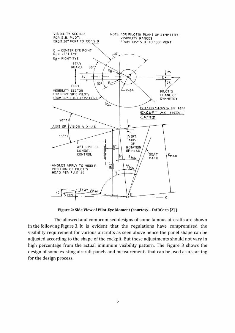
Figure 2: Side View of Pilot-Eye Moment (courtesy – DARCorp [2] )
The allowed and compromised designs of some famous aircrafts are shown
in the following Figure 3. It is evident that the regulations have compromised the
visibility requirement for various aircrafts as seen above hence the panel shape can be
adjusted according to the shape of the cockpit. But these adjustments should not vary in
high percentage from the actual minimum visibility pattern. The Figure 3 shows the
design of some existing aircraft panels and measurements that can be used as a starting
for the design process.
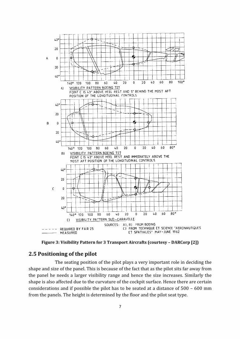
7
Figure 3: Visibility Pattern for 3 Transport Aircrafts (courtesy – DARCorp [2])
2.5 Positioning of the pilot
The seating position of the pilot plays a very important role in deciding the
shape and size of the panel. This is because of the fact that as the pilot sits far away from
the panel he needs a larger visibility range and hence the size increases. Similarly the
shape is also affected due to the curvature of the cockpit surface. Hence there are certain
considerations and if possible the pilot has to be seated at a distance of 500 – 600 mm
from the panels. The height is determined by the floor and the pilot seat type.

8
Figure 4: Transport aircraft cockpit arrangement and panels (courtesy – DARCorp [2] )
2.6 Computer Aided Design (CAD)
This part of the chapter gives a brief about the CAD tool being used in the
work. It is very important that the user knows the basics of CATIA V5 – Generative shape
designs module before using the work. CATIA V5 provides a very excellent platform for
surface modeling and generative shapes. There are many references [15, 16] and
tutorials available which can help the process of design and automation simpler. Two of
the automation concepts existing in CATIA are briefly discussed in this chapter. The
commonality between the two types of automation is that both need a template to be
instantiated according to the user requirement. In order to achieve a more stable and
flexible automation the user has to decide which on the following process will be
beneficial for him. In some cases the Power-copy (PC) process proves to be more
efficient than Knowledge Pattern (KP) method. In case where the template has to repeat
and instantiated a number of times, KP will be more helpful than PC. The advantages and
disadvantages of the both the methods are discussed below.
9
2.6.1 Power-copy
The Power-copy method of automation is a more widely and well know
method. The Power-copy method is one in which a set of components or elements are
grouped and then used at various location according to the user requirement. The main
advantage is that the Power-copy can adapt or reshape the grouped elements according
to the user input. There are advanced helping features available for this method. In this
method the user essentially creates a working template model and uses Visual Basics
scripting script to instantiate the template in the required part or product. The main
type of scripting used is VB script. The user needs to know basic knowledge about VB
script in order work or modify this script. The method has been one the most commonly
used design automation script.
Advantages
Instantiation can be done either in a part or a product. Modifications to the
result output are possible. Output contains all the elements of the template. This enables
the user to change the output even after instantiation. This provides high flexibility and
allows the possibility to adapt according to the requirement.
Can be repeated a number of times by changing the inputs accordingly. A
similar component which has to repeat in many places need not be designed every time.
It can be made as a template and instantiated at the required places according to the
user requirement.
The time period of usage of this method is more compared to the other
design automation technique (KP). Hence it is well established more common in the
design and development field.
More resources and help available [15, 16]. Possible to instantiate manually
or automatic. Mostly automatic is preferred in the process of time saving.
Inbuilt Macro recorder allows more convenience in finding out the exact
command or syntax the user needs to automate it. The user has to turn on the macro
recording facility and do the function he needs to automate.
Easy to link the parameters and outputs to external applications like Excel,
Notepad etc. By using this option the parametric model can be easily controlled and
modified at a single location in the excel file. This gives better usage of time during
automation process. The external link such as excel can be used as input for analysis
tools such as ANSYS to perform optimization calculations.
It is possible to stop or interrupt the script when required or even the script
can be executed by neglecting some type of errors which may be anticipated by the
user.

10
Disadvantages
Requires lengthy and complicated scripting procedure. The scripting
method might seem to be more complicated for beginners. It is an object oriented
scripting method. Hence all the parts or components used have to be saved under a
variable name before it can be used. Also the scripting has to specify to read the required
element from the entire product.
More time consuming than KP. This is because of the elements being used
inside the Template.
Debugging the script for errors might sometime become tedious. Since the
script might get longer as the product gets complicated it might be sometime difficult to
debug. Unless the Scripting is first debugged using a visual basics and then implemented
in the CATIA knowledge-ware it can be pretty time consuming. It is always advisable to
first write the script in VB and debug it simultaneously and then implement in CATIA.
Hard to reorganize the repeating elements or if the template need to be
done in different parts it might take more scripting.
Deleting an instantiated part needs a separate set of scripting.
2.6.2 Knowledge pattern scripting
This is another powerful tool used for design automation. This helps in
generating or creating the same part or component as done by the Power-copy. This
method has more advanced features than the VB script automation. There are large
amount of help available on this topic [15,16].This feature is really powerful compare to
that of the PC method, but it has its own advantages and disadvantages. Since it is yet to
be developed more, KP is only possible in geometric workbenches and not available in
drafting, system routing and few other workbenches in CATIA. The knowledge Pattern
method is also similar to the Power-copy, where only the selected output will be
available for the user and the output can be modified only using parameters. The inputs
for the Knowledge pattern are also selected by the user and modified, but the user does
not have the liberty to change the output, the user can modify output by making changes
in the input. An UDF is created and the required elements that define the output are
grouped under the UDF. Later a catalogue is created to link the file containing UDF. This
catalogue is invoked every time when the UDF needs to be used. The important step to
be followed is that the Working folder of the CATIA is defined in the following manner
while working on KP.
11
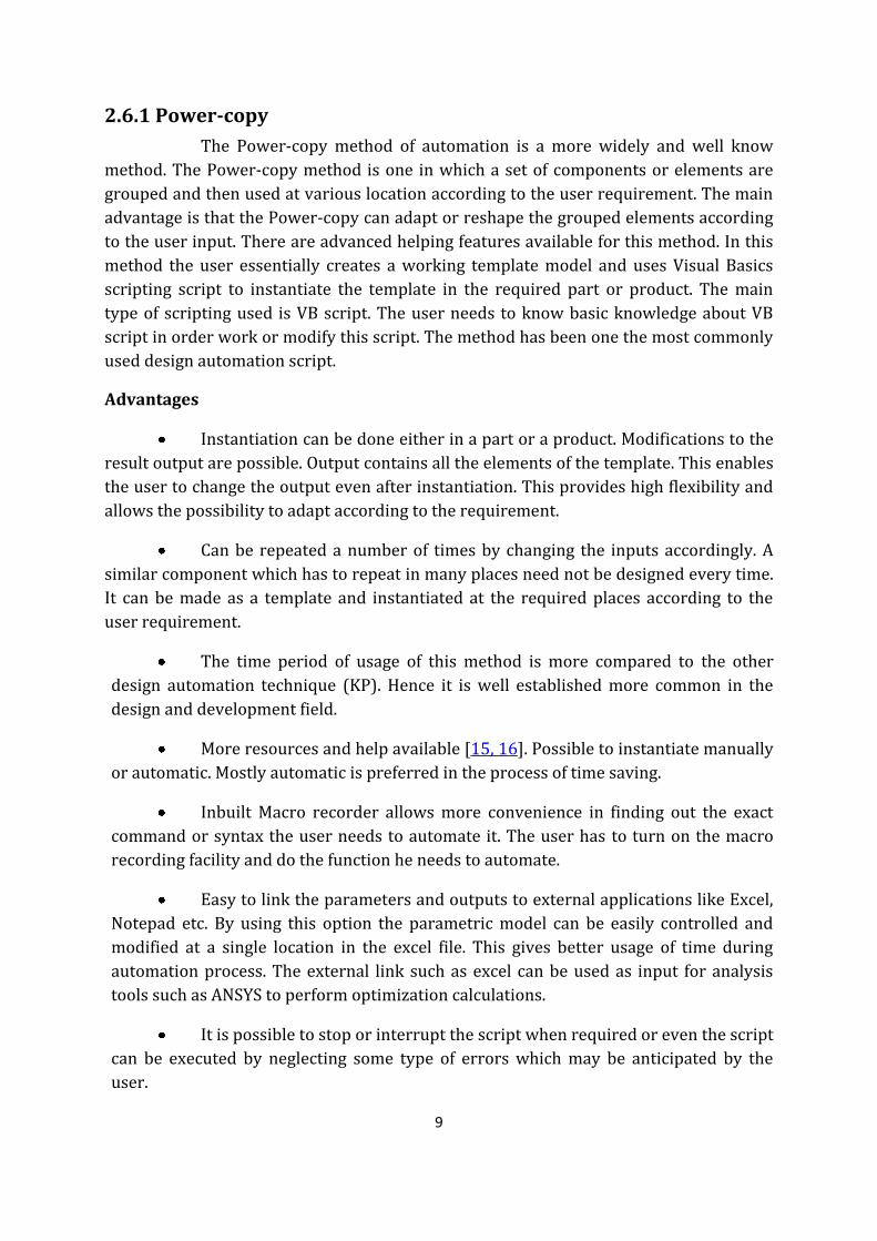
Figure 5: KP folder Set
Advantages
Comparatively less scripting or scripting required for this method.
Well organized and the possibility to create various lists reduces the
confusion in identifying the required element. Later these lists can also be changed and
modified.
Changes in the element name are updated automatically in the KP. This
reduce the amount to time spent in the script for every minor changes made in the
document.
Changes in the UDF are directly read by the KP script.
The KP does not require Change of path or location of the UDF as it will be
managed by the Catalogue created to link the UDF. It is important that the Catalogue file
remains inside the working folder of CATIA.
The KP interface is very similar to the knowledge advisor in CATIA to write
rules. Hence it is more simple and understandable.
Deletion and creation of components is a self-involved feature and it
depends on the value of the variable used for generation.
12
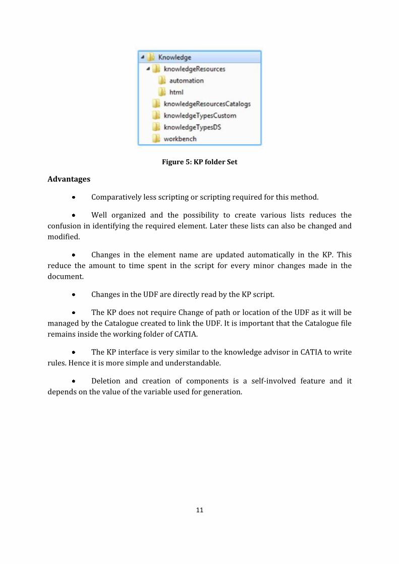
Figure 6:KP Script Editor
Disadvantages
It is difficult to access or link KP with External applications like Excel or
notepad.
Less resources and help files available for this method of automation
compared to PC method. Though once if the user understands the full scope of KP it will
be more time saving that the automated power-copy method.
Construction elements used for the output cannot be modified unless they
are linked with a control parameter. This makes it very difficult for the user to identify
the problem or error causing element in the UDF.
KP can be implemented in a single part alone. It cannot be instantiated in a
product or assembly.

13

14
Chapter 3 - CAD Method 3.1 Development of windshield
Aircraft windshield as described in the introduction part is divided in to
various types. Further in the topic, concept design implementation methods are
discussed in appropriate details with Figures. This will give a better understanding of
the underlying concepts in designing the panels in harmony with CAD interface CATIA
V5 R18.
Designing of windshield uses a common procedure between both flat panel
and blend panel. Both types of panels are subdivided in to different sections which are
listed below in respective panel types. These subdivisions assemble to form a complete
panel. Each of these subdivisions has its own parameters to control, which helps in
changing the shape of that subdivision as user needs.
To trigger the instantiation of these subdivided templates the user has
global set of parameters as an input. Each of this subdivision is to be instantiated one by
one in the same order and proper parameters are dedicated to control individually.
These parameters as well as global parameters will be discussed at the end of the panels,
since it requires understanding subdivisions at first.
Wind ShieldGlobal
parameters
Movable
Straight
WindowsStrutsVisibilityPattern
With Centre Panel
No Centre PanelStrut
Fuselage Blend
WindowsVisibility Pattern
Flat Surface
Flat Panel
Blend Panel
Figure 7: Automation framework for windshield
15
3.2 Windshield automation framework
Figure 7 gives a brief idea of how the automation framework for
windshield is designed to work. Each node represents the template instantiation, sibling
node can only be triggered only when the parent node is triggered and the input
parameter for that node allows that node to get instantiated.
In the above framework both type of panels are included. Input
parameters decide which node to follow. In both the panels, visibility pattern node plays
important role. If visibility pattern node is not allowed to instantiate then none of the
sibling nodes after this node will get instantiated. This flow at each node can be
controlled with global parameters assigned to windshield.
3.3 Flat panel windshield
Flat panel is subdivided into its basic elements and as usual it has a glass
window, struts and frames. Here to implement the concept in CAD, it has extra part
called Visibility Template, importance of it is explained below and how the other parts
work are described below.
Subdivision in Flat panel windshield:
The Flat panel windshield is subdivided into 4 major templates as listed below:
1. Basic Flat Surface Template
2. Visibility Template
3. Windows and struts
4. Fuselage Blend Template
3.3.1 Basic Flat Surface Template
Flat Surface Template is first major part which defines the windshield
surface. This template includes a flat surface. Inputs for this template will only be a point
& xy plane, which is pilot eye in this case and “xy plane” from global coordinates. Since
as mentioned in the concept part the panel should be at distance of 500mm to 600mm
from the pilot eye this flat surface template has its own parameter through which the
distance this surface can be controlled as user needs it to be. Flat Surface Template also
has other parameters which decide its inclination, swivel, size and position of the panel
with respect to pilot eye line as shown in the Figure 8.

16
Figure 8: Flat Surface Template and Parameters
In Figure 8, the yellow point is the reference point. It can be called as pilot
eye and the blue dotted line is the pilot line-of-sight.
The script used for automating this template positions the flat surface
appropriately with respect to the center point between two pilot eyes and star pilot eye,
further details will be explained in scripting part of flat surface template. For further
instantiation, yet it is recommended to position the panels as needed and then go for the
other subdivision instantiation with the instantiation control parameters.
Flat Surface Template is only a one part of complete panel, if the aircraft has
‘n’ number of panels, the template has to instantiated ‘n’ number of times and this is
controlled with the help of the global parameter in the tree, where user can enter the
number of panels to be present in the aircraft of interest. The end result will be one
single surface which looks like panel as in Figure 9. The script used for automating this
template positions the flat surface appropriately with respect to the center point
between two pilot eyes; further details will be explained in scripting part of flat surface
template. For further instantiation, yet it is recommended to position the panels as
needed and then go for the other subdivision instantiation with the instantiation control
parameters.
Figure 9: panel Join Surface
In Figure 9 shows left half of the windshield with yellow point as a point in
the center of two pilots and green point as star pilot eye. This surface is called “panel
Join” and this will later be made symmetric and joined to make one single surface in next
subdivision.
17
3.3.2 Visibility Template
Visibility Template is the second major part of windshield, since it decides
how much a pilot can see from his sitting position. This is the core concept of the flat
panel windshield and will decide the shape and size of the panels with respect to pilots
sitting position. After having the flat surface template positioned and one half of the
joined surface is made, this template reshapes the above panel join surface to the
visibility required.
The visibility pattern comprises of series of lines passing from the SPE and
CP and its angle can be varied with respect to horizontal with the help of parameters.
One half of the visibility pattern is divided in to five major sections which define the
shape and in these five sections the visibility can be controlled by changing the upper
and lower angles of view.
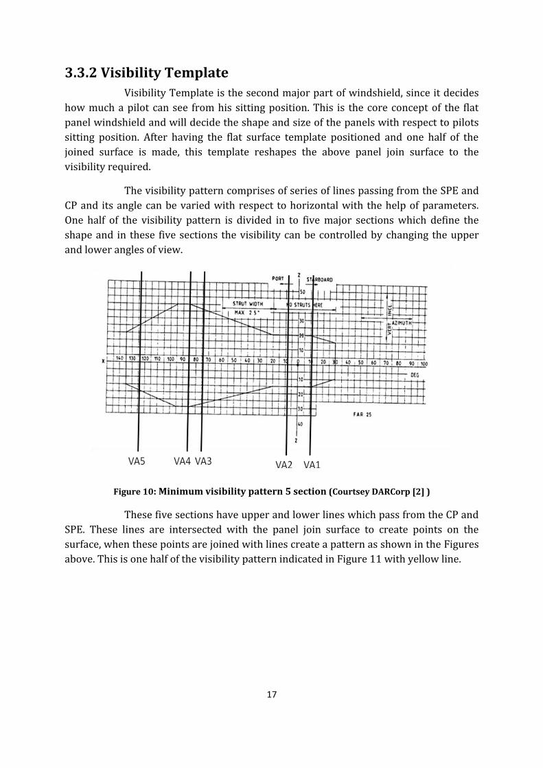
Figure 10: Minimum visibility pattern 5 section (Courtsey DARCorp [2] )
These five sections have upper and lower lines which pass from the CP and
SPE. These lines are intersected with the panel join surface to create points on the
surface, when these points are joined with lines create a pattern as shown in the Figures
above. This is one half of the visibility pattern indicated in Figure 11 with yellow line.

18
Figure 11: Half Side MVP
The above visibility lines can be controlled with dedicated parameters list.
Each set of lines which divide the total visibility has 3 lines one in middle one above and
one below. The middle line parameter Pilot_Va1 or Pilot_VA2 or similar parameter till
Pilot_VA5 decide the position of other two lines along the standard visibility pattern and
based on the position of middle line the lower and upper lines position is decided from
the standard or minimum visibility pattern Figure 10.
After achieving the half of the visibility pattern for one of the pilot, the
panel join is cut with the pattern to get half of the panel. This half of the panel is made
symmetry to get the basic structure of the whole panel with minimum visibility pattern
criteria satisfied as shown in the Figure 12.
Figure 12: Complete panel with Parameters
Figure 12 shows the windshield with six panels as an example. Outer frame
is extracted from the same profile of visibility pattern and its thickness can be controlled
with the parameter in the list.
19
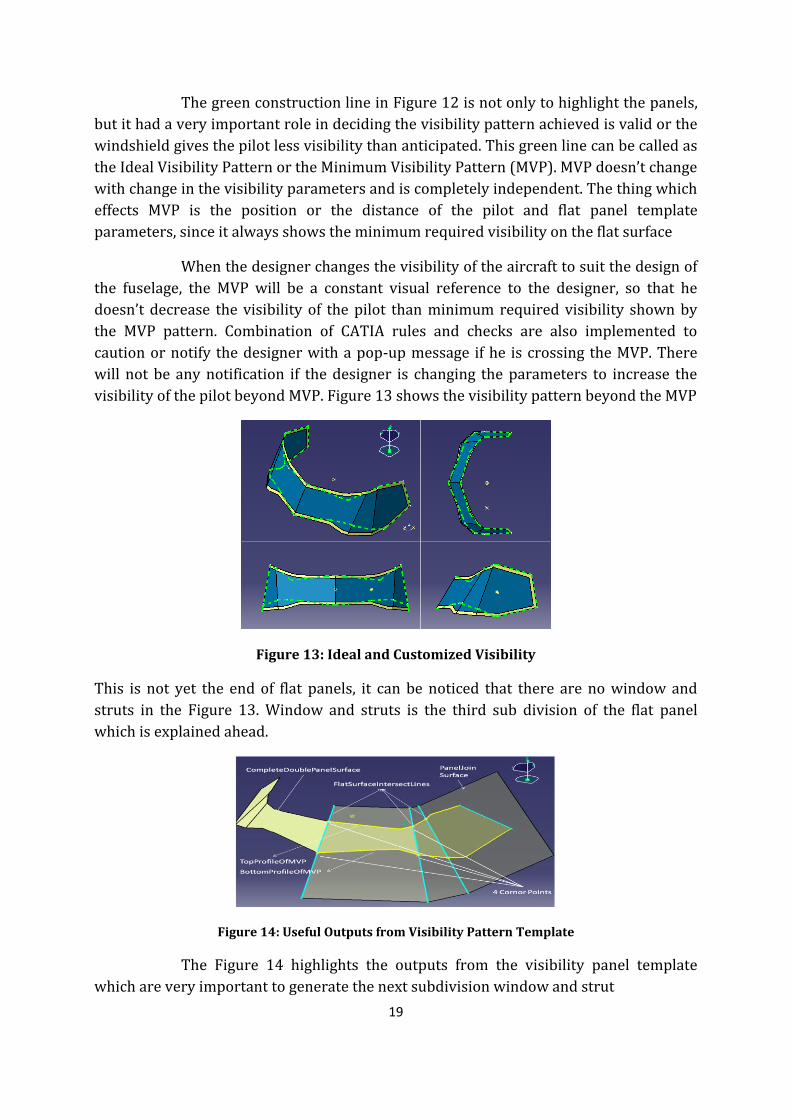
The green construction line in Figure 12 is not only to highlight the panels,
but it had a very important role in deciding the visibility pattern achieved is valid or the
windshield gives the pilot less visibility than anticipated. This green line can be called as
the Ideal Visibility Pattern or the Minimum Visibility Pattern (MVP). MVP doesn’t change
with change in the visibility parameters and is completely independent. The thing which
effects MVP is the position or the distance of the pilot and flat panel template
parameters, since it always shows the minimum required visibility on the flat surface
When the designer changes the visibility of the aircraft to suit the design of
the fuselage, the MVP will be a constant visual reference to the designer, so that he
doesn’t decrease the visibility of the pilot than minimum required visibility shown by
the MVP pattern. Combination of CATIA rules and checks are also implemented to
caution or notify the designer with a pop-up message if he is crossing the MVP. There
will not be any notification if the designer is changing the parameters to increase the
visibility of the pilot beyond MVP. Figure 13 shows the visibility pattern beyond the MVP
Figure 13: Ideal and Customized Visibility
This is not yet the end of flat panels, it can be noticed that there are no window and
struts in the Figure 13. Window and struts is the third sub division of the flat panel
which is explained ahead.
Figure 14: Useful Outputs from Visibility Pattern Template
The Figure 14 highlights the outputs from the visibility panel template
which are very important to generate the next subdivision window and strut
20
3.3.3 Windows and struts
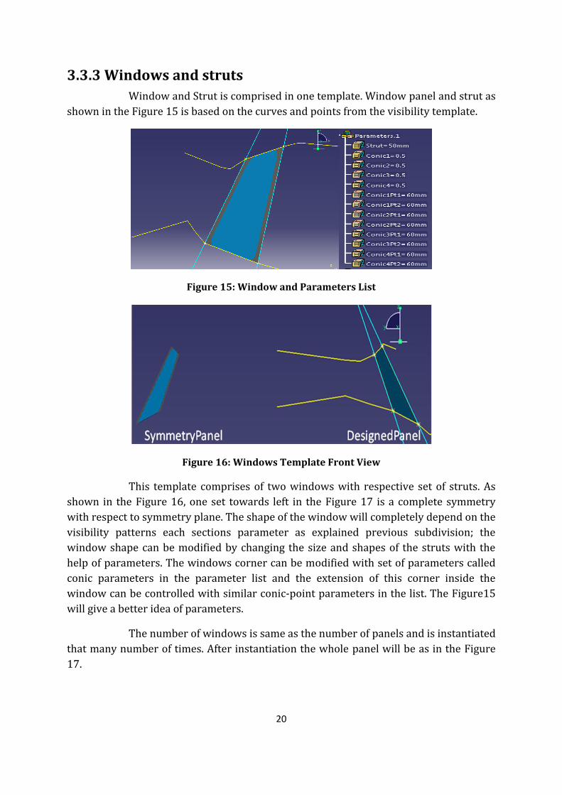
Window and Strut is comprised in one template. Window panel and strut as
shown in the Figure 15 is based on the curves and points from the visibility template.
Figure 15: Window and Parameters List
Figure 16: Windows Template Front View
This template comprises of two windows with respective set of struts. As
shown in the Figure 16, one set towards left in the Figure 17 is a complete symmetry
with respect to symmetry plane. The shape of the window will completely depend on the
visibility patterns each sections parameter as explained previous subdivision; the
window shape can be modified by changing the size and shapes of the struts with the
help of parameters. The windows corner can be modified with set of parameters called
conic parameters in the parameter list and the extension of this corner inside the
window can be controlled with similar conic-point parameters in the list. The Figure15
will give a better idea of parameters.
The number of windows is same as the number of panels and is instantiated
that many number of times. After instantiation the whole panel will be as in the Figure
17.

21
Figure 17: panels with Windows and Struts
3.3.4 Fuselage Blend Template
Fuselage Blend Template is an option given to suit with the windshield.
This template will make the windshield a part of fuselage. This can be called as
interaction between the fuselage and windshield. Fuselage blend template modifies the
fuselage to suit with windshield and makes blending surface between fuselage and
windshield.
Template has a list of parameters to control its shape at some points since it
does not adjust itself to proper shape after instantiation. The user has to change the
parameters manually to get the smooth surfaces in the blend. Surfaces are controlled by
skeleton frame highlighted in green which can be controlled with parameters as shown
in Figures 18.
Figure 18: Fuselage Blend Template with Skeleton Structure and Parameters
22
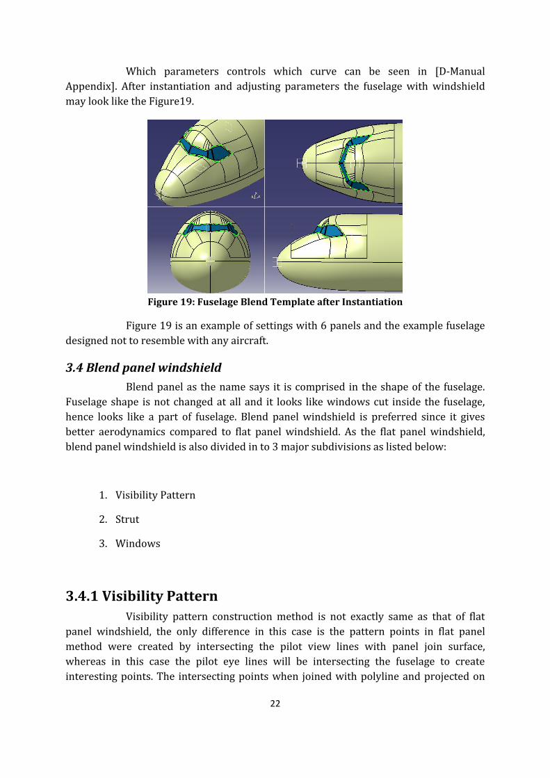
Which parameters controls which curve can be seen in [D-Manual
Appendix]. After instantiation and adjusting parameters the fuselage with windshield
may look like the Figure19.
Figure 19: Fuselage Blend Template after Instantiation
Figure 19 is an example of settings with 6 panels and the example fuselage
designed not to resemble with any aircraft.
3.4 Blend panel windshield
Blend panel as the name says it is comprised in the shape of the fuselage.
Fuselage shape is not changed at all and it looks like windows cut inside the fuselage,
hence looks like a part of fuselage. Blend panel windshield is preferred since it gives
better aerodynamics compared to flat panel windshield. As the flat panel windshield,
blend panel windshield is also divided in to 3 major subdivisions as listed below:
1. Visibility Pattern
2. Strut
3. Windows
3.4.1 Visibility Pattern
Visibility pattern construction method is not exactly same as that of flat
panel windshield, the only difference in this case is the pattern points in flat panel
method were created by intersecting the pilot view lines with panel join surface,
whereas in this case the pilot eye lines will be intersecting the fuselage to create
interesting points. The intersecting points when joined with polyline and projected on
23
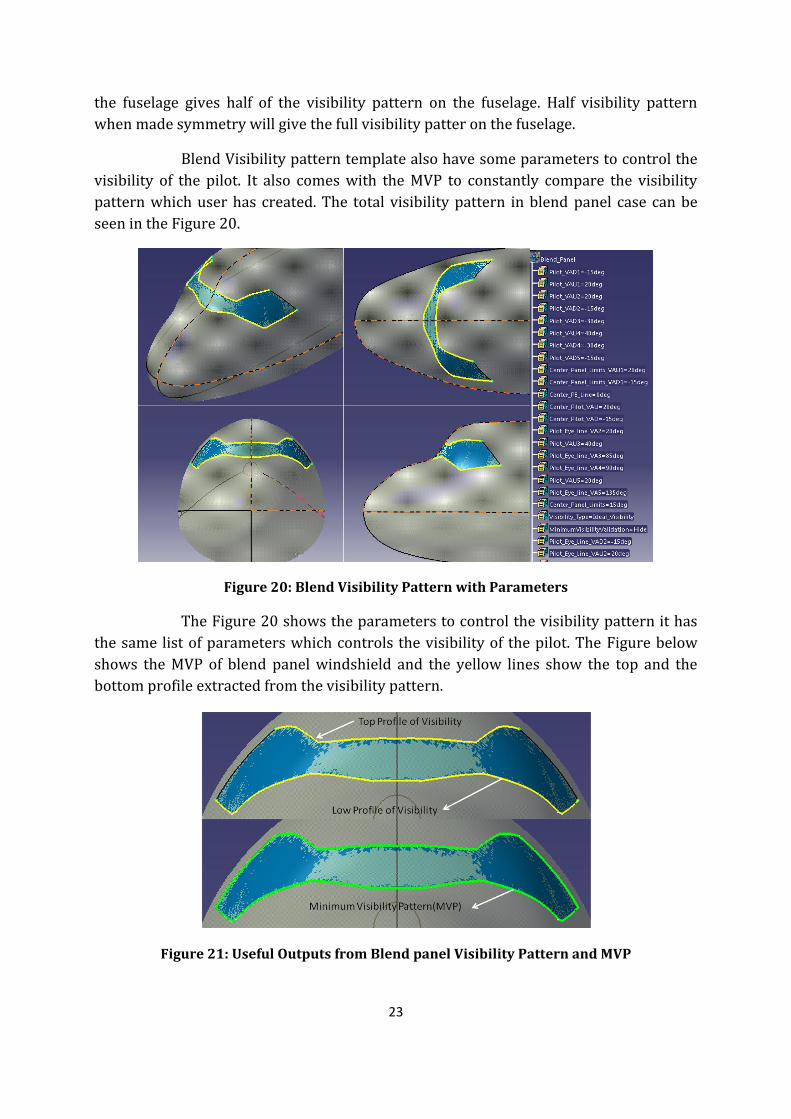
the fuselage gives half of the visibility pattern on the fuselage. Half visibility pattern
when made symmetry will give the full visibility patter on the fuselage.
Blend Visibility pattern template also have some parameters to control the
visibility of the pilot. It also comes with the MVP to constantly compare the visibility
pattern which user has created. The total visibility pattern in blend panel case can be
seen in the Figure 20.
Figure 20: Blend Visibility Pattern with Parameters
The Figure 20 shows the parameters to control the visibility pattern it has
the same list of parameters which controls the visibility of the pilot. The Figure below
shows the MVP of blend panel windshield and the yellow lines show the top and the
bottom profile extracted from the visibility pattern.
Figure 21: Useful Outputs from Blend panel Visibility Pattern and MVP

24
The useful outputs of the visibility pattern are top profile and low profile
curves as shown in Figure 21 highlighted in yellow. These two outputs will be used as an
input to the next subdivision struts.
3.4.2 Strut
Strut template decides the position of the struts in the blend panel
windshield based on the number of windows the user has given and it is instantiated
“n+1” number of times for “n” number of windows. If the number of panels is even then
there is a strut in the center of or if the number of panels is odd then there is a panel in
the center as shown in the Figure 26. By using the parameters in this template user can
decide if he needs to move the struts later or would like to fix the struts as decided by
the template.
Figure 22: Effect of Change in Number of panels and Strut Parameters
The strutTopPointRatio can always be moved by changing the value
appropriately and value will be between 0 and 1. strutLowPointMovableRatio is active
when the blendStrut parameter is set to “Movable” value. To leave the template decides
how strut looks change the blendStrut parameter to “Straight”. The Figure 23 shows
what difference the blendStrut parameter makes to the panels.
Figure 23: Variation of Strut Type
The after deciding the position of the struts the outputs from the strut
template part will be points on the top profile and low profile of the visibility pattern.
These will be the inputs in the next subdivision called windows.
25
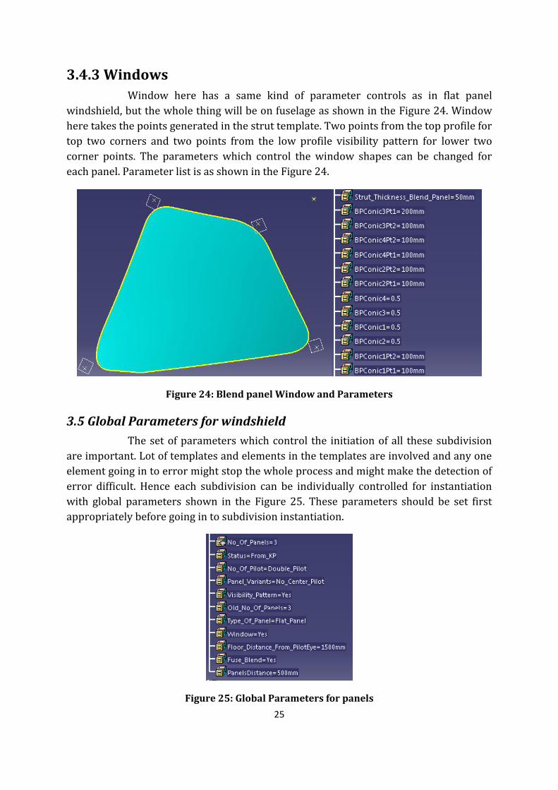
3.4.3 Windows
Window here has a same kind of parameter controls as in flat panel
windshield, but the whole thing will be on fuselage as shown in the Figure 24. Window
here takes the points generated in the strut template. Two points from the top profile for
top two corners and two points from the low profile visibility pattern for lower two
corner points. The parameters which control the window shapes can be changed for
each panel. Parameter list is as shown in the Figure 24.
Figure 24: Blend panel Window and Parameters
3.5 Global Parameters for windshield
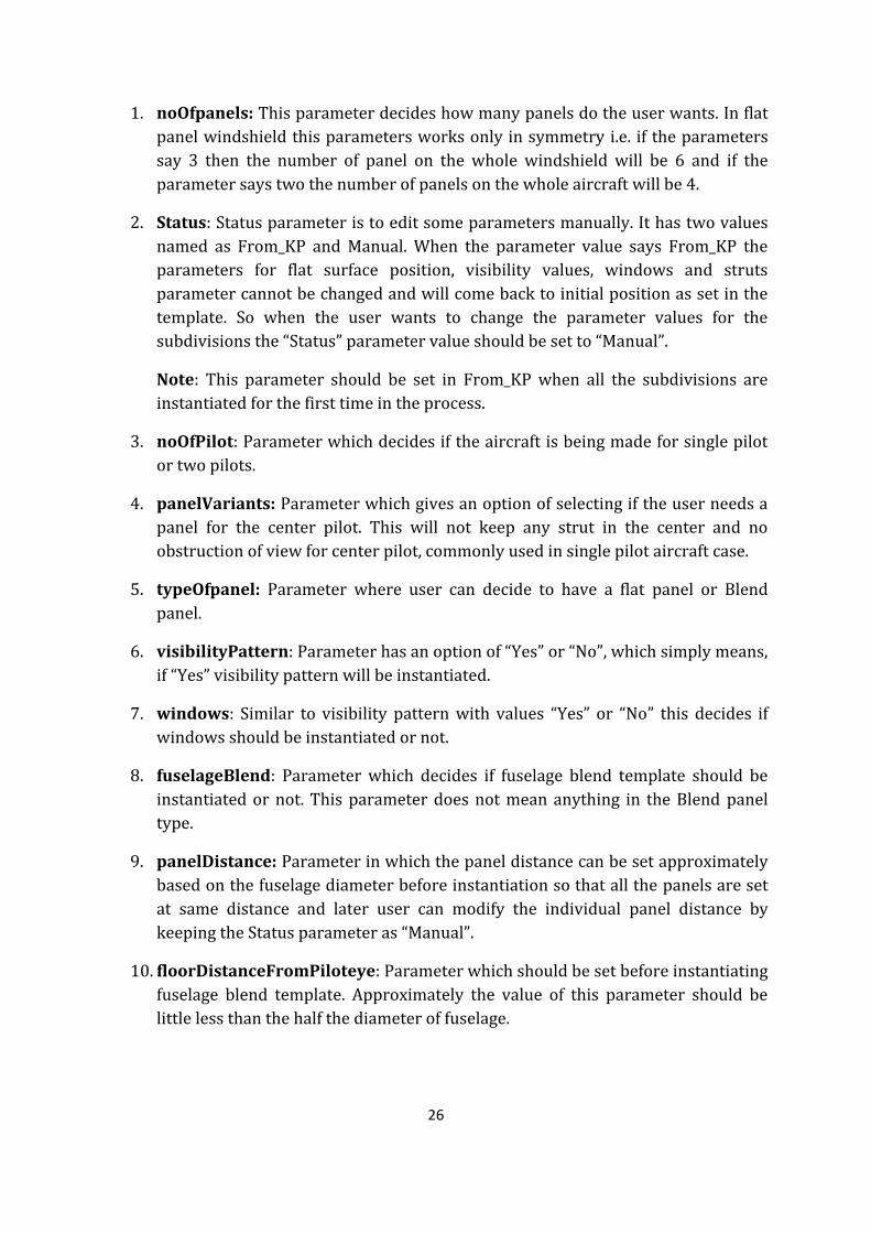
The set of parameters which control the initiation of all these subdivision
are important. Lot of templates and elements in the templates are involved and any one
element going in to error might stop the whole process and might make the detection of
error difficult. Hence each subdivision can be individually controlled for instantiation
with global parameters shown in the Figure 25. These parameters should be set first
appropriately before going in to subdivision instantiation.
Figure 25: Global Parameters for panels
26
1. noOfpanels: This parameter decides how many panels do the user wants. In flat
panel windshield this parameters works only in symmetry i.e. if the parameters
say 3 then the number of panel on the whole windshield will be 6 and if the
parameter says two the number of panels on the whole aircraft will be 4.
2. Status: Status parameter is to edit some parameters manually. It has two values
named as From_KP and Manual. When the parameter value says From_KP the
parameters for flat surface position, visibility values, windows and struts
parameter cannot be changed and will come back to initial position as set in the
template. So when the user wants to change the parameter values for the
subdivisions the “Status” parameter value should be set to “Manual”.
Note: This parameter should be set in From_KP when all the subdivisions are
instantiated for the first time in the process.
3. noOfPilot: Parameter which decides if the aircraft is being made for single pilot
or two pilots.
4. panelVariants: Parameter which gives an option of selecting if the user needs a
panel for the center pilot. This will not keep any strut in the center and no
obstruction of view for center pilot, commonly used in single pilot aircraft case.
5. typeOfpanel: Parameter where user can decide to have a flat panel or Blend
panel.
6. visibilityPattern: Parameter has an option of “Yes” or “No”, which simply means,
if “Yes” visibility pattern will be instantiated.
7. windows: Similar to visibility pattern with values “Yes” or “No” this decides if
windows should be instantiated or not.
8. fuselageBlend: Parameter which decides if fuselage blend template should be
instantiated or not. This parameter does not mean anything in the Blend panel
type.
9. panelDistance: Parameter in which the panel distance can be set approximately
based on the fuselage diameter before instantiation so that all the panels are set
at same distance and later user can modify the individual panel distance by
keeping the Status parameter as “Manual”.
10. floorDistanceFromPiloteye: Parameter which should be set before instantiating
fuselage blend template. Approximately the value of this parameter should be
little less than the half the diameter of fuselage.

27
3.6 Development of fairings
The design process of this work took lot of initial considerations to keep the
design as simple as possible. The very important aspect of this work was to keep the
design datum components as basic as possible. By achieving this, flexibility of the design
has increased a lot. Basic components like points, line, spline and conics where used in
most cases to form the basic geometry of the fairings. Later simple and stable surface
generation elements like multi-sections are used for surface generation. Initially for the
process of automation, it is important that a stable and flexible template of the
Component is designed parametrically. Once this is achieved it is further simple to
implement these components in the VB script and knowledge pattern script in CATIA.
The more and detailed design made in the template helps to find different ways to
implement in the script. It is also important that the number of inputs used for a
particular template must be as low as possible. The input for the instantiation also needs
to be the very basic components like planes, points, lines, surfaces and curves.
The fairing templates are designed in a certain fashion and the inputs used
for the instantiation is also required that the orientation is same. If the user has inverted
orientation it is suggested that the inputs are refined first and then instantiate.
Low WingFairing
Mid Wing Fairing
High Wing Fairing
T -Tail
FairingParameters
Conventional
Horizontal tail Fairing
Vertical tail Fairing
Main Wing
Empennage
Figure 26: Automation framework for fairing
3.7 Fairing automation framework
Figure 26 shows the basic automation framework for fairing. It takes the
input from the parameters assigned to fairings and instantiates. This framework is
similar to windshield framework, where flow along the tree can be controlled with the
parameters and each end node represents the instantiated output.

28
3.8 Fairing
The discussion for the requirement for a fairing, apart from the
aerodynamics is that it is also important that the design is capable of providing the
required volume for certain type of components. For that to be accomplished the design
needs to be more flexible such that the volume and the shape will be useful. Also the
fairing should provide appropriate aerodynamic advantage. In order to achieve the
flexibility, it is necessary to use the required parameters for the constructions elements.
The need for the fairing to take various shapes for different configurations is also very
important. This is possible by using sketches which can be modified. These sketches
define the shape of and the parameters help in getting a better adjustment of those
shapes.
There are basically three major configurations of the wing. Fairings of the
configurations serve different purpose and hence the templates for the automation have
to be different from one another. Major work had to be done in the template such that it
is flexible. Any change which has to be implemented in the automated part has to be
implemented in template. Hence the more flexible the template is, the more flexible the
final part will be. In this chapter a brief discussion about the templates for various
configurations is given. A better understanding of the elements used for the
construction of the templates will give the user a very clear idea about the limitations
and flexibility.
3.8.1 Low fairing template
The fairing for the low wing configurations mostly has the necessity for
placing any component under it. The component can be anything from the main landing
gear or an environmental control system etc. The low fairing had to provide more space
under the wing for placing ground accessible components also. The three sketches used
in the template helps the use to modify it according to the requirement. The template
needs certain inputs to be instantiated as shown in Figure 27.
Figure 27: Inputs required for low fairing template
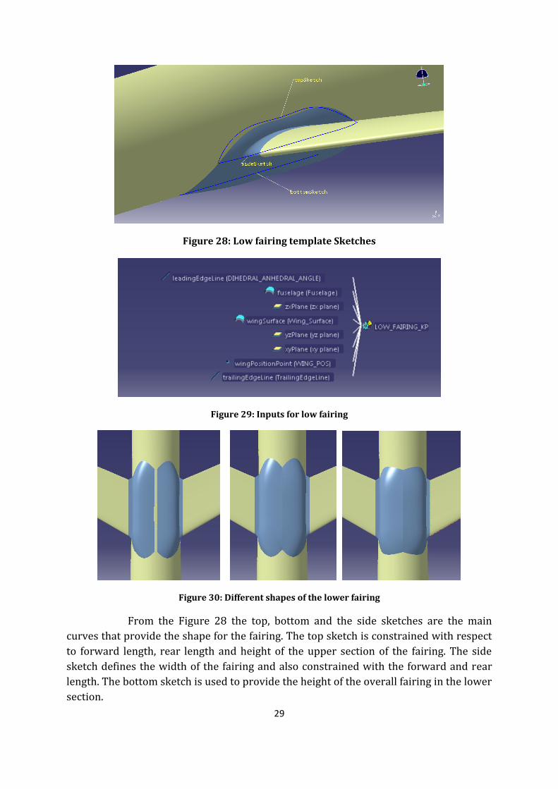
29
Figure 28: Low fairing template Sketches
Figure 29: Inputs for low fairing
Figure 30: Different shapes of the lower fairing
From the Figure 28 the top, bottom and the side sketches are the main
curves that provide the shape for the fairing. The top sketch is constrained with respect
to forward length, rear length and height of the upper section of the fairing. The side
sketch defines the width of the fairing and also constrained with the forward and rear
length. The bottom sketch is used to provide the height of the overall fairing in the lower
section.
30
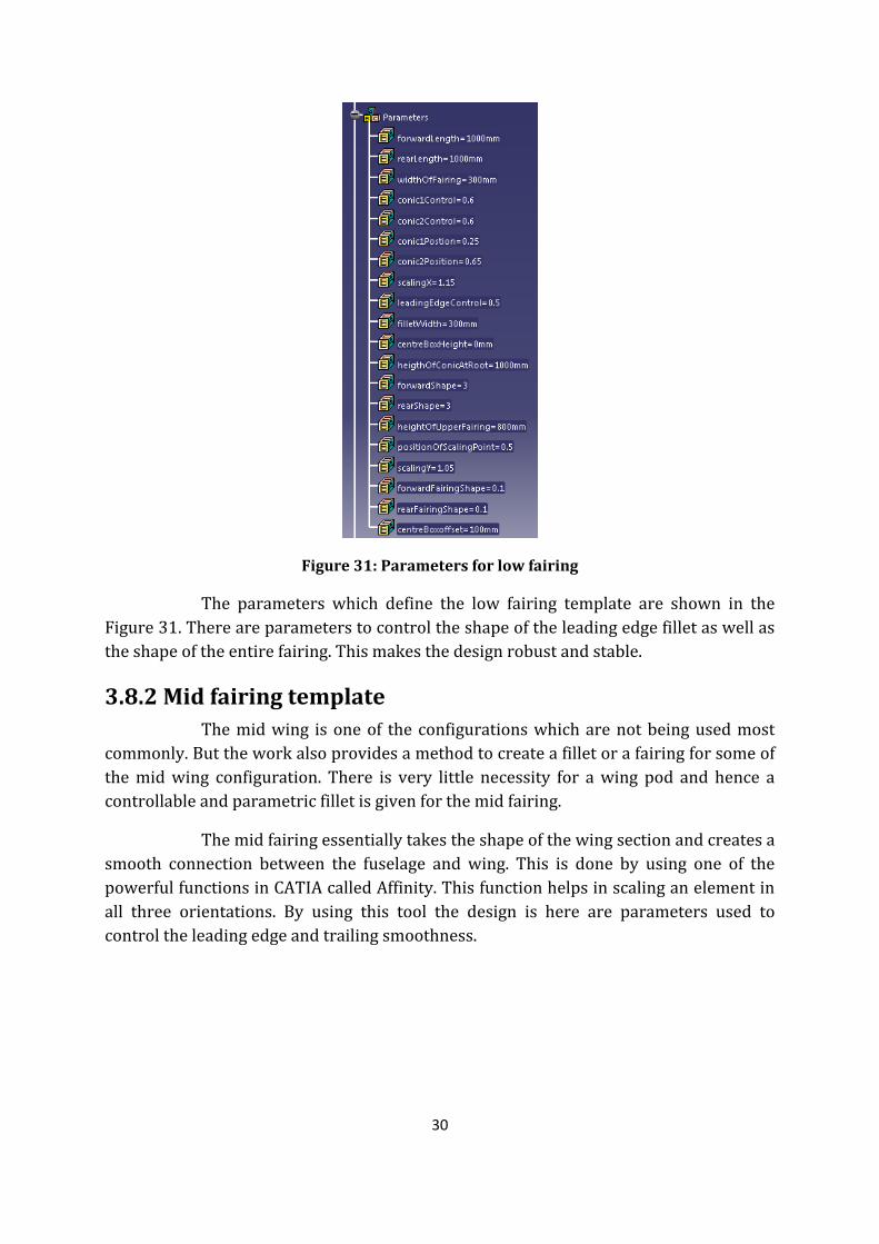
Figure 31: Parameters for low fairing
The parameters which define the low fairing template are shown in the
Figure 31. There are parameters to control the shape of the leading edge fillet as well as
the shape of the entire fairing. This makes the design robust and stable.
3.8.2 Mid fairing template
The mid wing is one of the configurations which are not being used most
commonly. But the work also provides a method to create a fillet or a fairing for some of
the mid wing configuration. There is very little necessity for a wing pod and hence a
controllable and parametric fillet is given for the mid fairing.
The mid fairing essentially takes the shape of the wing section and creates a
smooth connection between the fuselage and wing. This is done by using one of the
powerful functions in CATIA called Affinity. This function helps in scaling an element in
all three orientations. By using this tool the design is here are parameters used to
control the leading edge and trailing smoothness.
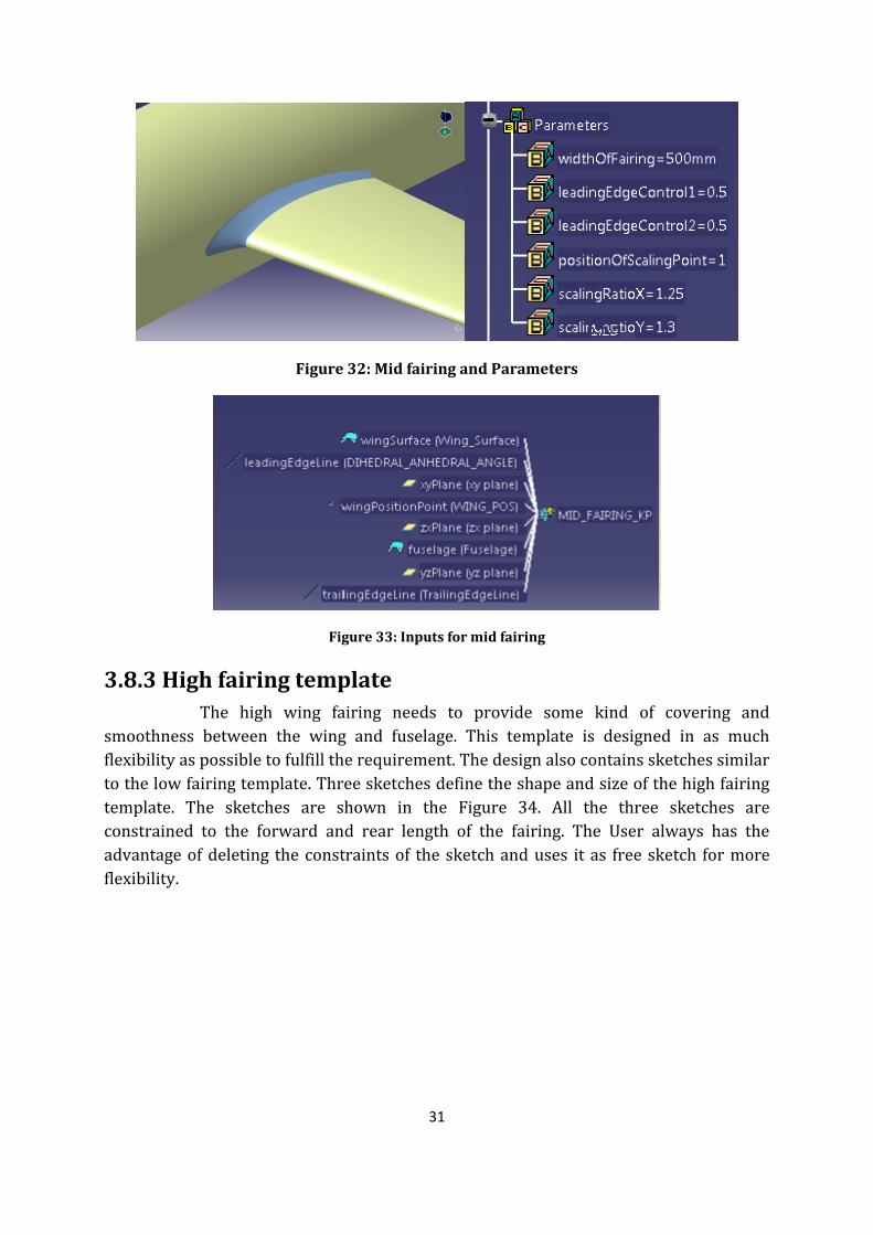
31
Figure 32: Mid fairing and Parameters
Figure 33: Inputs for mid fairing
3.8.3 High fairing template
The high wing fairing needs to provide some kind of covering and
smoothness between the wing and fuselage. This template is designed in as much
flexibility as possible to fulfill the requirement. The design also contains sketches similar
to the low fairing template. Three sketches define the shape and size of the high fairing
template. The sketches are shown in the Figure 34. All the three sketches are
constrained to the forward and rear length of the fairing. The User always has the
advantage of deleting the constraints of the sketch and uses it as free sketch for more
flexibility.
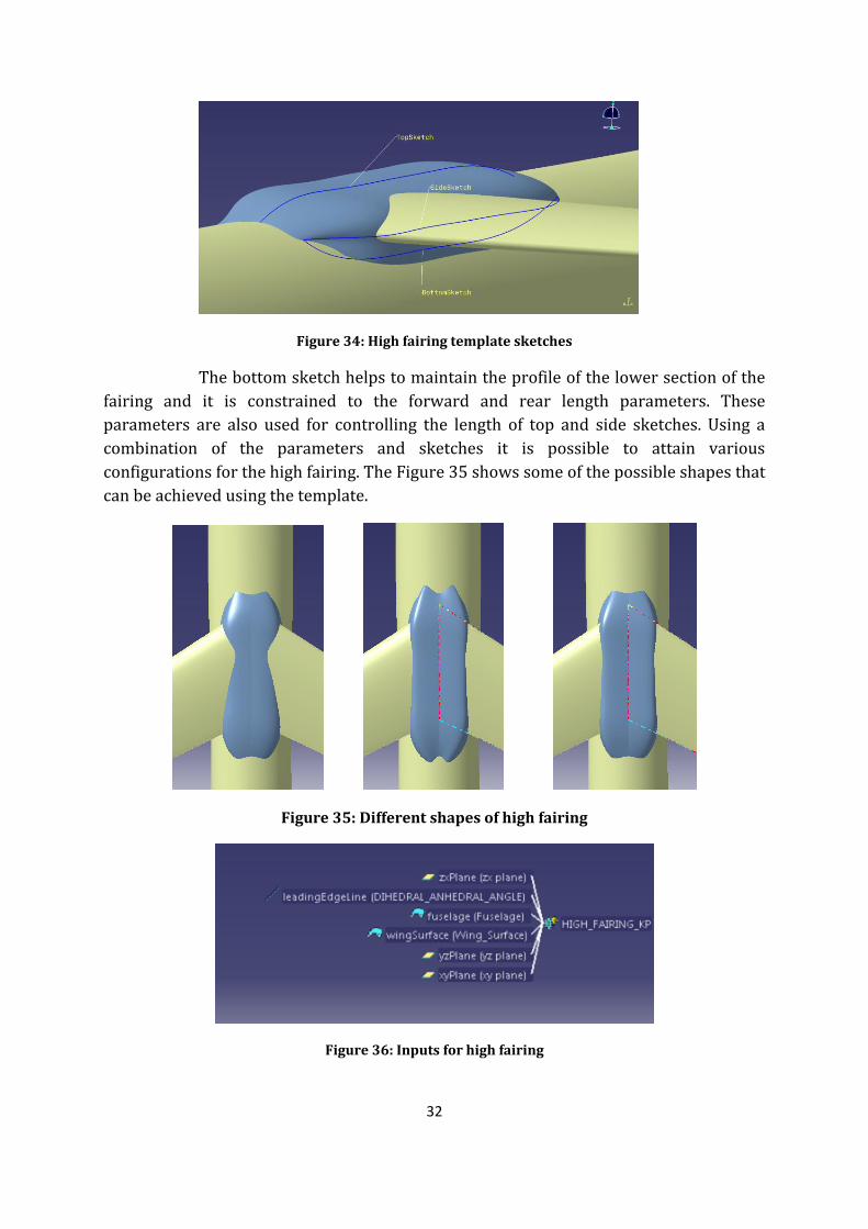
32
Figure 34: High fairing template sketches
The bottom sketch helps to maintain the profile of the lower section of the
fairing and it is constrained to the forward and rear length parameters. These
parameters are also used for controlling the length of top and side sketches. Using a
combination of the parameters and sketches it is possible to attain various
configurations for the high fairing. The Figure 35 shows some of the possible shapes that
can be achieved using the template.
Figure 35: Different shapes of high fairing
Figure 36: Inputs for high fairing
33
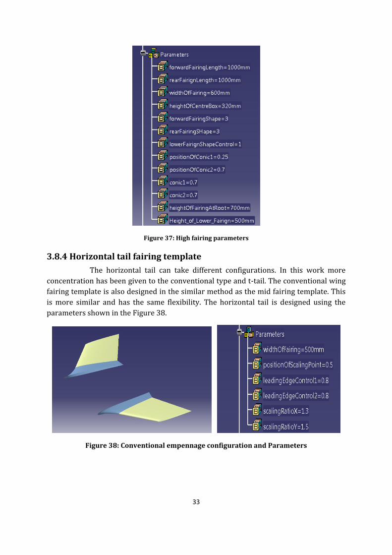
Figure 37: High fairing parameters
3.8.4 Horizontal tail fairing template
The horizontal tail can take different configurations. In this work more
concentration has been given to the conventional type and t-tail. The conventional wing
fairing template is also designed in the similar method as the mid fairing template. This
is more similar and has the same flexibility. The horizontal tail is designed using the
parameters shown in the Figure 38.
Figure 38: Conventional empennage configuration and Parameters
34
Figure 39: Inputs for Conventional Tail
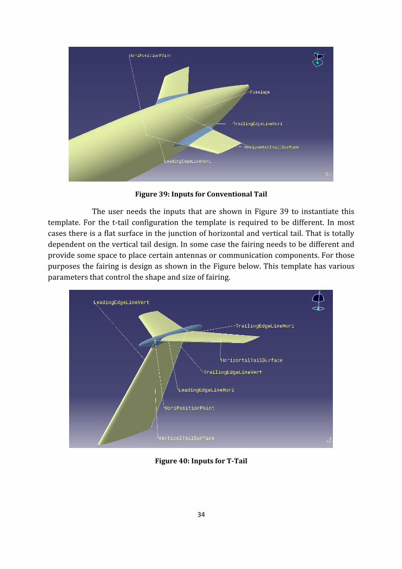
The user needs the inputs that are shown in Figure 39 to instantiate this
template. For the t-tail configuration the template is required to be different. In most
cases there is a flat surface in the junction of horizontal and vertical tail. That is totally
dependent on the vertical tail design. In some case the fairing needs to be different and
provide some space to place certain antennas or communication components. For those
purposes the fairing is design as shown in the Figure below. This template has various
parameters that control the shape and size of fairing.
Figure 40: Inputs for T-Tail

35
Figure 41: T-Tail fairing and Parameters
3.8.5 Vertical tail fairing template
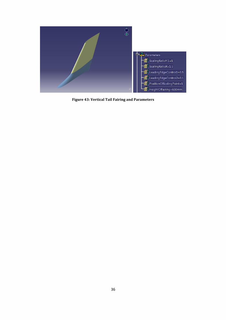
The vertical tail fairing template is designed in a way that it is possible to
take the shapes of existing fairings and also flexible to take new shapes. The vertical
fairing is designed more with same concept as that of the mid fairing with some more
parameters for flexibility. The Figure below shows the required inputs for the template.
Figure 42: Inputs for Vertical Tail Fairing
The Figure 43 shows the parameters used for controlling the shape and size
of the fairing. This template more commonly takes the shape of the vertical tail profile. If
the user needs to have another profile, it is possible to replace the affinity curve with
any other profile.
36
Figure 43: Vertical Tail Fairing and Parameters

37
38
Chapter 4 - Results
In results, the flexibility of the designs and validation method is mentioned.
Existing aircrafts are taken as a base to validate the designs of fairings, windshield
panels and portray the flexibility of the same models. These designs can be morphed to
take shape of many of the existing aircrafts which have a similar configuration as
considered here.
The validation of windshield panels and fairings is done with visual
comparison. This method does not ensure 100% matching of the designs, but will give a
fare idea that CAD models have flexibility to take shape of many existing fairings and
windshield panels. Here an example of two aircrafts fairing and windshield comparison
is shown using available pictures. The full fuselage is not included in comparison
pictures since designing of fuselage is out of scope of this project. Dummy fuselage
sections are used at main fairing, empennage and cockpit to display the fairings and
windshield position with respect to fuselage.
The comparison of two types of windshield, fairing for three different
position of main wind and few standard configurations of empennage is done as follows:

39
4.1 Comparison of windshield panels:
4.1.1 Blend panel windshield
Figure 44: Blend panel Comparison with Boeing 787
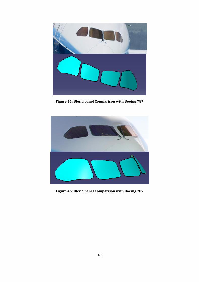
Figure 44 shows the comparison of blend panel’s windshield with Boeing
787. The green line pattern is minimum visibility pattern (MVP). MVP is used to
compare the visibility pattern achieved. This is not the only way to match the windshield
of Boeing 787; there are many parameters which can be changed to achieve better
results. The panel mapped does not satisfy the MVP at some points that does not mean
even Boeing 787 does not satisfy MVP, it’s just for user to look if the visibility achieved is
satisfactory or not.
40
Figure 45: Blend panel Comparison with Boeing 787
Figure 46: Blend panel Comparison with Boeing 787

41
Figure 47: Blend panel Comparison with Boeing 787

42
4.1.2 Flat panel windshield
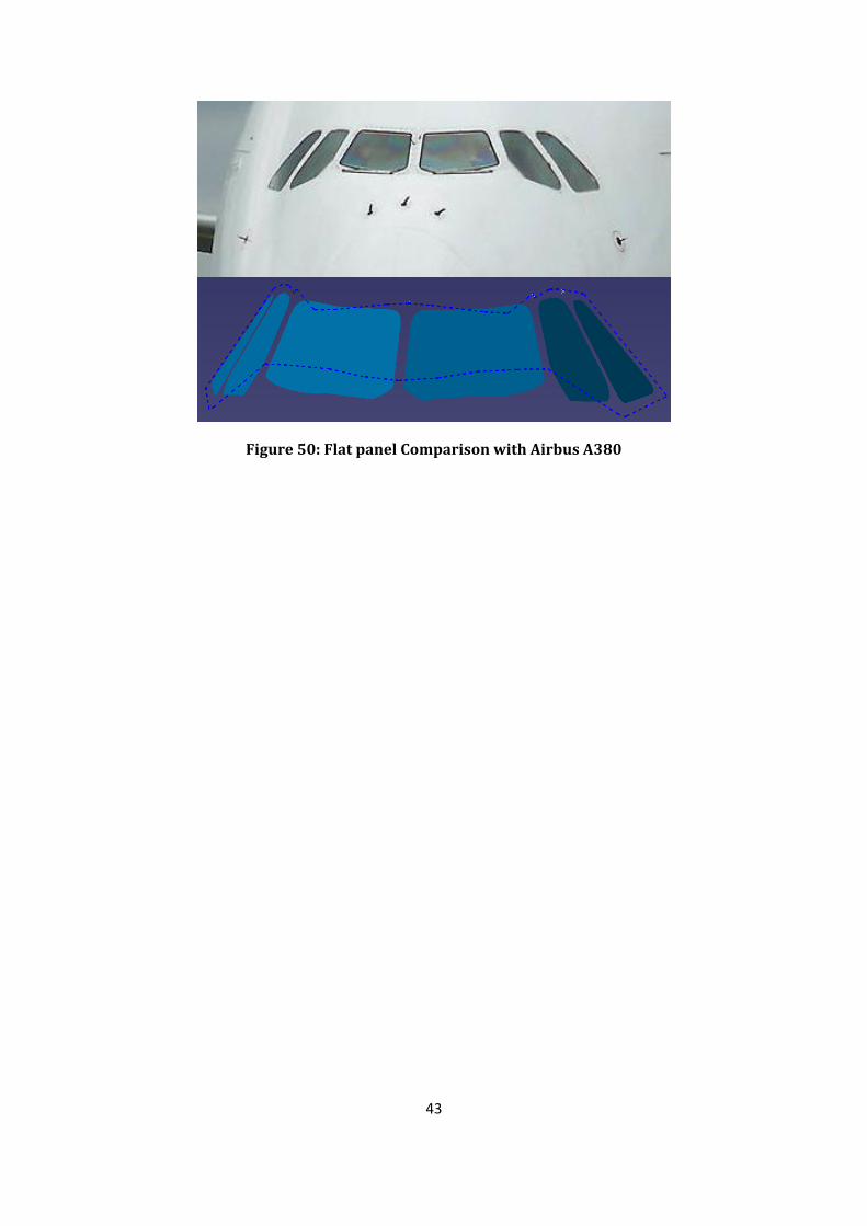
Comparison of the flat panel windshield is done on Airbus A380. Following
are some comparison pictures.
Figure 48: Flat panel Comparison with Airbus A380
Figure 49: Flat panel Comparison with Airbus A380
43
Figure 50: Flat panel Comparison with Airbus A380

44
4.2 Comparison of fairings
The Figure below shows a comparison between the Actual Airbus A380
main wing fairing and the CAD model of this work. From the work it is evident that the
work is capable of taking the shape of the fairing of A380. It can be more accurate if the
dimensions of the wing, fuselage and fairing sections are exactly available. The work is
also instantiated to roughly map the shape of the Main fairing of Boeing 787. The shape
of the fairing is more defined by the shape of fuselage and wing. With proper
dimensioning of the fuselage and wing the result is highly efficient.
Figure 51: Main wing fairing visual comparison of A380
Figure 52: Main wing fairing visual comparison of A380
45
Figure 53: Main wing fairing visual comparison of Boeing 787
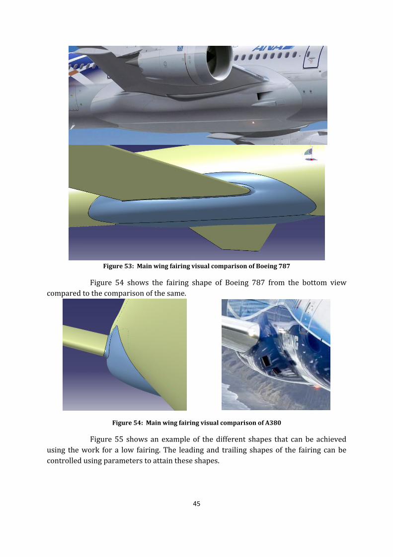
Figure 54 shows the fairing shape of Boeing 787 from the bottom view
compared to the comparison of the same.
Figure 54: Main wing fairing visual comparison of A380
Figure 55 shows an example of the different shapes that can be achieved
using the work for a low fairing. The leading and trailing shapes of the fairing can be
controlled using parameters to attain these shapes.

46
Figure 55: Different shapes of low wing fairing
Figure 56: Antonov 148 high wing Aircraft main fairing
Figure 57: Antonov 148 high wing Aircraft main fairing
Figure 58: Different shapes of high wing fairing

47
Figure 59: Faring for different shapes of fuselage
Figure 59 shows the possibility of the fairing to be used on different cross
sections of the fuselage. This is an example of the flexibility available in the work. The
three main wing configurations with two different fuselage cross section is shown in this
Figure.
Comparison of Empennage
Figure 60: Comparison of Boeing 787 Vertical tail fairing

48
Figure 61: Comparison of Airbus A380 Vertical tail fairing
The Figure below shows the four view of the Vertical fairing. This is one of
the most commonly used fairing structures.
Figure 62: Most Commonly used vertical fairing
The t-tail configuration shown below is also a common occurrence in
certain type of high wing aircrafts.
Figure 63: T-Tail Configuration

49
Figure 64: Four view of t-tail configuration
Figure 65 : Cessna Citation C12 T-Tail
Figure 66 : Illusion 69 T-tail
Figure 67 : Tupoleve 154 t-tail
50
The Figures in this section shows the various configurations that are
possible using this work. The work shown is comparison with few existing aircrafts with
similar configuration. With exact dimension of the input parts more accurate shape of
existing aircrafts are possible.
An observation was carried out to find the time required for a particular
instantiation of the components. The table shows the recorded time needed for
instantiating the components using PC method and KP. This shows that PC method is
very useful and quick for single part instantiation and KP is quicker for repeating
number of instantiation. As discussed earlier the PC provides advantage for the user to
gain access to the constructions elements of the out. This can be very useful to make
final changes and get desired shapes. At the same time the KP provides the ease of
scripting. Both the methods have their own advantages for the different types of
requirement. The Figure and table below explains the observation recorded.

51
4.3 Time Comparison
In this part of the work a comparison between the time taken for
instantiating the components is done. By doing this analysis it is better to find out an
efficient method of automation for different components. The comparison of time for VB
is introduced in the script from which the user is able to find out the exact time a
particular computer takes to instantiate. For the knowledge pattern time was recorder
manually.
4.3.1 Flat panel
Table 1 shows the time taken for instantiating the flat panel on a particular
fuselage. Time taken for both KP and PC are measured and tabulated.
Flat panels (seconds)
KP 4-6 panels 4-8 panels 4-10 panels 4-12 panels
Instantiation 8.8 10.4 10.4 10.8
Deletion 5.9 6.1 6.6 6.7
PC 4-6 panels 4-8 panels 4-10 panels 4-12 panels
Instantiation 24 25.5 26.1 28.3
Deletion 12.3 13.5 13.9 18.4
Table 1: Time taken for flat panel instantiation
Figure 68 is the plot of the observations for flat panel and it is very clear
that the KP consumes less time compared to the PC automation method. The
observations are made by changing the number panels form 4 to 12 in an increment of
two panels every time. KP consumes approximately half the time taken by PC. Even
though the difference in the time is in seconds, during a process of optimization where
this might be repeated many time, an efficient method will prove time saving.
Figure 68: Time comparison for flat panel KP and PC instantiation
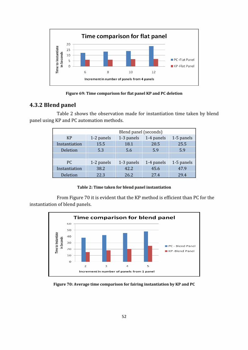
52
Figure 69: Time comparison for flat panel KP and PC deletion
4.3.2 Blend panel
Table 2 shows the observation made for instantiation time taken by blend
panel using KP and PC automation methods.
Blend panel (seconds)
KP 1-2 panels 1-3 panels 1-4 panels 1-5 panels
Instantiation 15.5 18.1 20.5 25.5
Deletion 5.3 5.6 5.9 5.9
PC 1-2 panels 1-3 panels 1-4 panels 1-5 panels
Instantiation 38.2 42.2 45.6 47.9
Deletion 22.3 26.2 27.4 29.4
Table 2: Time taken for blend panel instantiation
From Figure 70 it is evident that the KP method is efficient than PC for the
instantiation of blend panels.
Figure 70: Average time comparison for fairing instantiation by KP and PC
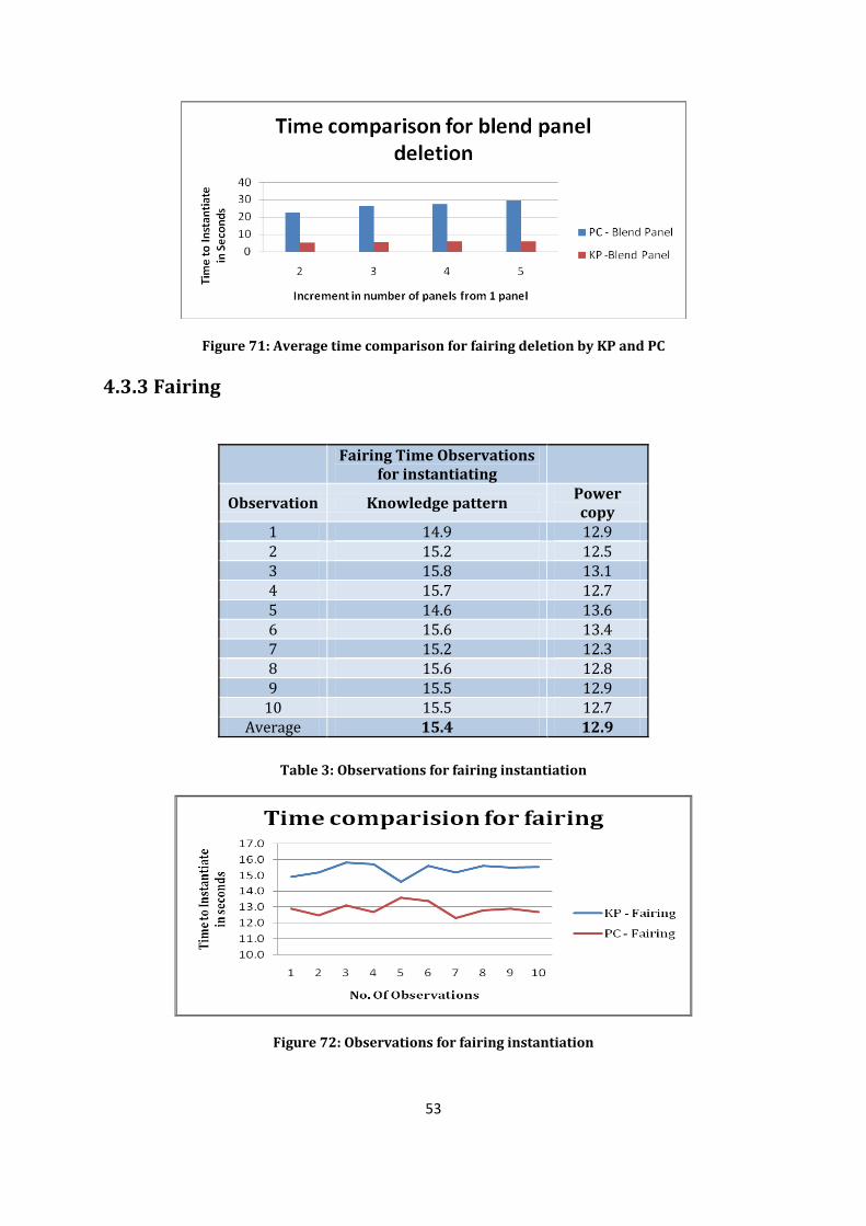
53
Figure 71: Average time comparison for fairing deletion by KP and PC
4.3.3 Fairing
Fairing Time Observations for instantiating
Observation Knowledge pattern
Power copy
1 14.9 12.9 2 15.2 12.5 3 15.8 13.1 4 15.7 12.7 5 14.6 13.6 6 15.6 13.4 7 15.2 12.3 8 15.6 12.8 9 15.5 12.9
10 15.5 12.7 Average 15.4 12.9
Table 3: Observations for fairing instantiation
Figure 72: Observations for fairing instantiation
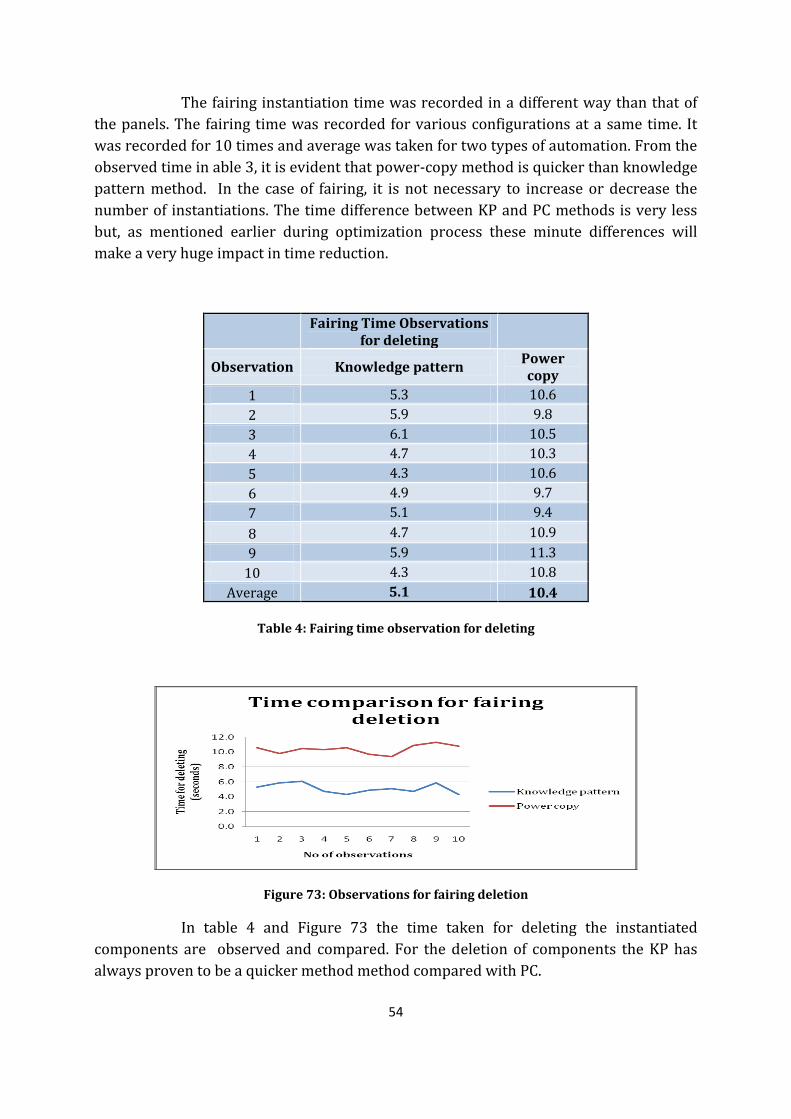
54
The fairing instantiation time was recorded in a different way than that of
the panels. The fairing time was recorded for various configurations at a same time. It
was recorded for 10 times and average was taken for two types of automation. From the
observed time in able 3, it is evident that power-copy method is quicker than knowledge
pattern method. In the case of fairing, it is not necessary to increase or decrease the
number of instantiations. The time difference between KP and PC methods is very less
but, as mentioned earlier during optimization process these minute differences will
make a very huge impact in time reduction.
Fairing Time Observations for deleting
Observation Knowledge pattern
Power copy
1 5.3 10.6
2 5.9 9.8
3 6.1 10.5
4 4.7 10.3
5 4.3 10.6
6 4.9 9.7
7 5.1 9.4
8 4.7 10.9
9 5.9 11.3
10 4.3 10.8
Average 5.1 10.4
Table 4: Fairing time observation for deleting
Figure 73: Observations for fairing deletion
In table 4 and Figure 73 the time taken for deleting the instantiated
components are observed and compared. For the deletion of components the KP has
always proven to be a quicker method method compared with PC.

55
56
Chapter 5 - Conclusion and Future works
5.1 Conclusion
With this work as a starting for conceptual design stage, the user is sure of
saving a lot of design work time. Considerable amount of time spent on the design can be
reduced by using the work as an initial base. Since the work is parametric it is also
flexible and can be modified according to the requirements. Automation of the work is
the main advantage where the user can save time in initial work as well as rework. The
two types of automation methods, KP and PC used in this work were compared and a
better way of automation was suggested to the user. The work provides the option for
the user to select between the two types of automation.
While considering the outputs of fairing, it is notable that the work needs
post-instantiation work to be done to get the desired shape. These post work are mainly
because of the use of sketches to control the shapes. As discussed in the theory section
[2.6.2], the output elements like sketches from this automation process cannot be
modified according to the user requirement without parameters. The manual control
over the sketches is more flexible than controlling using parameters. Hence according to
this work the PC is more efficient for fairings. KP is also a good method of instantiation
with appropriate inputs. Also there is no pattern requirement in case of fairing, so there
is no need for the increase or decrease in the number of fairing used. In such cases it is
suggested that the user can work with PC automation rather than KP automation.
The windshield has more flexibility and there is a very little need for the
user to actually change any of the construction or output elements to get the appropriate
shape. The wind panels can be controlled very effectively using the parameters. The
main reason for KP to be more efficient is because the windshield involves multiple
instantiation of same template. The VB script for such process will include a very long
and complicated scripting process. One requirement for the user to be more careful
about would be to make sure that the fuselage is already designed properly with having
the type of panel to be used in mind. So in the case of wind panels, KP is an efficient and
more time saving method of automation.
57
5.2 Future work
5.2.1 Flow Automation and optimization
The work provides a platform for to further analyze the aerodynamic
qualities of fairing and panels. This can be a useful tool while further automating the
process of analysis. The part of fairing which is parametrically controlled can be
automated and optimized according to the volume required. The automation of the
analysis work can be done by keeping the volume required inside the fairing as a
constant and modifying the shape to get better flow near the place of fuselage and wing
intersection.
A connection between the CATIA work and an analysis tool like Ansys CFX
can be achieved through scripting. The final design of fairing can be imported to Ansys
and in the same way, the meshing can also be automated to compute a flow analysis. The
user can define the parameters used in the CATIA design and optimize the shape and
size based on the required volume. By doing so an improved fairing structure can be
obtained and again the man hours required for meshing and analysis can be reduced.
5.2.2 Optimization of windshield
The work can be extended further in optimizing the fuselage and
windshield according to the user requirement. The optimization can be done based on
flow analysis or based on visibility requirement of the mission statement. Since this
work can be used in various shapes of cockpit fuselage, it can be modified and a
universal optimization method can be derived. An automated process can be done in
appropriate tool to optimize the shape of the windshield. The windshield can also be
implemented with thickness and material to perform stress analysis and derive the
appropriate requirement for material thickness according to the FAR.
5.2.3 Fairing for Pylon, External Radar, AEWS, AWACS
The work can be used as an initial base for the generation of fairing for
other external components like the engine pylon, AEW&C and AWACS attachments etc.
The work can be used for this implementation with minor changes in the template used
for the Vertical tail fairing. This work can also be extended to the generation of fillets for
external antennas and pitot tubes or any similar external measurement devices.

58
59
References
[1] (R.Hansen, The Wind and Beyond-A Documentary Journey into the History of Aerodynamics in America Vol II, 2007)
[2] Roskam, D. (1985). Airplane Design Volume 2. Kansas: Roskam Aviation and Engineering Corporation.
[3] Sohaib, M. (2011). Parameterized Automated Generic Model for Aircraft Wing Structural Design and Mesh Generation for Finite Element Analysis. Linkoping.
[4] Tassel, W. (2010). Development of Parametric Cockpit CAD model for civil aircraft using CATIA V5. Linkoping.
[5] H.Muttray. (1935). The Aerodynamic Aspect of Wing-Fuselage Fillets.
[6] L. R. Kubendran, H.McMahon and J.Hubbartt. (1984 July). Interference Drag in a Simulated Wing-Fuselage Juncture.
[7] McClellan, J. (1993). Citation Jet is Better than the Original. Flying Magazine .
[8] R.Hansen, J. (2004). Aerodynamics and the Progress of the American Airplane-The bird is on the wing.
[9] R.Hansen, J. (2007). The Wind and Beyond-A Documentary Journey into the History of Aerodynamics in America Vol II.
[10] Raymer, D. P. (1989). Aircraft Design-A Conceptual Approach.
[11] Sherman, A. (1938). Interference of Wing and Fuselage from Tests of Eight Combinations in the NACA Variable-Density Tunnel Combinations with Tapered Filledts and Straight-Side Junctures. Washington.
[12] Smith, H. (1992). The Illustrated Guide to Aerodynamics, 2nd Edition. TAB Books.
[13] Supamusdisukul, J. (2008). Experimental Investigation of Wing-Fuselage Integration Geometries including CFD Analysis. University of Maryland.
[14] Federal Aviation Regulations (FAR) – 25 & 23 section 775 windshields and Windows
[15] www.3ds.com – help files and tutorials.
[16] http://V5vb.wordpress.com – CATIA V5 release forum.
[17] Kleismit, F. K. (2004). Using CATIA V5. NewYork.
[18] Product modeling course material TMKT 57- Linkoping University.
60
Appendix
A - Appendix - KP Script for panels let udf (UserFeature) let BlendWindowudf(UserFeature) let VP_udf(UserFeature) let VP_U(UserFeature) let Strut_UDF(UserFeature) let Strut_UDF1(UserFeature) let panel_F(UserFeature) let panel_F1(UserFeature) let panel_F2(UserFeature) let Blend_UDF(UserFeature) let i (Integer) let j(Integer) let k(Integer) let Flat_S(Feature) let Flat_H(Feature) let Flat_S1(Surface) let Flat_S2(Surface) let surf1(Surface) let surf2(Surface) let zx_ref(Plane) let Sp(Surface) let Join_P(Surface) let surf_split(Surface) let Intersect_line_1(Curve) let Intersect_line_2(Curve) let panel_Pos(Feature) let length1(Length) let dg(Real) let panel_Dist(Integer) let New_P(Integer) let Old_P(Integer) let Test_Line1 (Line) let Test_Line1 (Line) let Inter_Line(Line) let Center_EP(Point) let Test_Pt (Point) let Test_Len (Length) let Intersect_FS (Feature) let Intersect_Line(Curve) let CRV1(Curve) let CRV2(Curve) let Inter_Pt(Point) let Inter_Pt2(Point) let Inter_Pt1(Point) let V4_U_Pt(Point) let V4_D_Pt(Point) let V2_D_Pt(Point)
61
let Pt1(Point) let Pt2(Point) let Pt3(Point) let list_Split(List) let VP_CRV(Point) let BPlane(Plane) let Obs_Chk1(Real) let Obs_Chk2(Real) let Chk1(Real) /***************'blend panel variables*/ let udf(UserFeature) let position (String) let j(Integer) let o(Real) let i(Real) let Pt_Top(Point) let Pt_Bottom(Point) let Top_curve(Curve) let Bottom_curve(Curve) let Top_Pt(Point) let Bottom_Pt(Point) let Blend_Feat(UserFeature) let Win_udf(UserFeature) let Input_Pt_Top_1(Point) let Input_Pt_Top_2(Point) let Input_Pt_Bottom_1(Point) let Input_Pt_Bottom_2(Point) let Str(String) set New_P=Parameters->GetAttributeInteger("No_Of_panels") if Type_Of_panel == "Flat_panel" { if New_P >=2 { i=0 for i while i<= No_Of_panels { udf = CreateOrModifyTemplate("Flat_Surf_Catalog|Flat_Surf_UDF",panel_Pattern ,`Relations\Knowledge Pattern.1\UDFs`,i) if No_Of_Pilot == "Double_Pilot" { if panel_Variants =="No_Center_Pilot" { udf->SetAttributeObject("Piloteye_pt",`External References\Star_Piloteye` ) } else { if i==1 {
62
udf->SetAttributeObject("Piloteye_pt",`External References\Center_Piloteye` ) } else { udf->SetAttributeObject("Piloteye_pt",`External References\Star_Piloteye` ) } } } udf->SetAttributeObject("Ref_XY",`External References\refXY` ) EndModifyTemplate(udf) udf.Name = "panel." +ToString(i) Flat_S = udf->GetAttributeObject("Flat_Surf") Flat_S.Name = "Flat_S_" + ToString(i) set surf1=Flat_S surf1.Show = False } /* Positioning the panel*/ j=1 dg=(80deg/(No_Of_panels+1*0.3))*0.8 if Status == "From_KP" { for j while j <=No_Of_panels { panel_F = `Relations\Knowledge Pattern.1\UDFs`->GetItem(j) Flat_S = panel_F->GetAttributeObject("Flat_Surf") panel_F.Show = false if j>1 { panel_F.SetAttributeReal( "panel_Pos.1",dg * j) panel_F.SetAttributeReal( "panel_Dist.1",panelsDistance ) } if j<>No_Of_panels and panel_Variants =="panel_For_Center_Pilot" and j==1 { panel_F.SetAttributeReal( "panel_Swivel.1",92deg)
63
panel_F.SetAttributeReal( "panel_Inclination.1",60deg) panel_F.SetAttributeReal( "panel_Dist.1",panelsDistance ) } else { panel_F.SetAttributeReal( "panel_Swivel.1",110deg) panel_F.SetAttributeReal( "panel_Inclination.1",60deg) panel_F.SetAttributeReal( "panel_Dist.1",panelsDistance ) } } } /*Intersecting Flat_surfaces*/ j=1 for j while j<No_Of_panels { Intersect_FS = CreateOrModifyDatum("Curve",panel_Pattern ,`Relations\Knowledge Pattern.1\Intersect_Lines`,j) panel_F = `Relations\Knowledge Pattern.1\UDFs`->GetItem(j) panel_F1 = panel_F set surf1=panel_F1 panel_F = `Relations\Knowledge Pattern.1\UDFs`->GetItem(j+1) panel_F2 = panel_F set surf2=panel_F2 Intersect_FS = intersect(surf1,surf2) set Inter_Line=Intersect_FS Inter_Line.Show = false Intersect_FS.Name = "Intersect_FS" +ToString(j) + "_" + ToString(j+1) if j==1 { Intersect_FS = CreateOrModifyDatum("Curve",panel_Pattern ,`Relations\Knowledge Pattern.1\Intersect_Lines`,No_Of_panels) Intersect_FS = intersect(surf1,`zx plane`) /*Intersect_FS->Update()*/ Intersect_FS.Name = "Intersect_FS1_ZX" +ToString(j) set Inter_Line=Intersect_FS Inter_Line.Show = false }

64
} j=1 for j while j <=No_Of_panels { surf_split=CreateOrModifyDatum("Surface",panel_Pattern ,`Relations\Knowledge Pattern.1\split1` ,j) panel_F1 = `Relations\Knowledge Pattern.1\UDFs`->GetItem(j) if j<No_Of_panels { panel_F2 = `Relations\Knowledge Pattern.1\UDFs`->GetItem(j+1) set surf1 = panel_F1 set surf2 = panel_F2 surf_split=split(surf1,surf2,false) surf_split.Name = "S_Split" + ToString(j) } else { panel_F2 = `Relations\Knowledge Pattern.1\UDFs`->GetItem(j-1) } set surf1 = panel_F1 set surf2 = panel_F2 surf_split=split(surf1,surf2,false) surf_split.Name = "S_Split" + ToString(j) surf_split.Show = false } j=1 for j while j <No_Of_panels { surf_split=CreateOrModifyDatum("Surface",panel_Pattern ,`Relations\Knowledge Pattern.1\split2` ,j) if j==1 { panel_F1 = `Relations\Knowledge Pattern.1\split1` ->GetItem(j) set surf1 = panel_F1 set zx_ref =`zx plane` surf_split=split(surf1,zx_ref,false) surf_split.Name = "S_Split2." + ToString(j) surf_split.Show = false } else if j>1 and j<No_Of_panels { panel_F1 = `Relations\Knowledge Pattern.1\split1` ->GetItem(j)
65
panel_F2 = `Relations\Knowledge Pattern.1\split1` ->GetItem(j-1) set surf1 = panel_F1 set surf2 = panel_F2 surf_split=split(surf1,surf2,false) surf_split.Name = "S_Split2." + ToString(j) surf_split.Show = false } } if No_Of_panels >=2 { surf1=`Relations\Knowledge Pattern.1\split1`->GetItem(No_Of_panels) `Relations\Knowledge Pattern.1\split2`->AddItem(surf1,No_Of_panels) Join_P=CreateOrModifyDatum("Surface",panel_Pattern ,`Relations\Knowledge Pattern.1\panel_Join` ,1) set Join_P=assemble(`Relations\Knowledge Pattern.1\split2` ) Join_P.Show = false Join_P.Name = "panel_Join" Old_No_Of_panels=No_Of_panels } if Visibility_Pattern == "Yes" { if No_Of_panels >= 2 { Join_P.Show = false if No_Of_Pilot == "Double_Pilot" { VP_udf=CreateOrModifyTemplate("Vis_Pat_Double_Cat|Vis_Pat_Double",panel_Pattern,`Relations \Knowledge Pattern.1\Vis_Pat` ,1) VP_udf->SetAttributeObject("Center_Eye",`External References\Center_Piloteye` ) VP_udf->SetAttributeObject("PilotEye",`External References\Star_Piloteye` ) VP_udf->SetAttributeObject("Flat_S", Join_P) VP_udf->SetAttributeObject("XY_Plane",`xy plane` ) VP_udf->SetAttributeObject("ZX_Plane",`zx plane` ) EndModifyTemplate(VP_udf) VP_udf.Name = "Visibility_Pattern_Double" VP_udf.Show=false } set CRV2 = VP_udf->GetAttributeObject("Ideal_Visibility_Profile") if deleted_String =="Hide"
66
{ CRV2.Show=false } else { CRV2.Show= true } } k=1 for k while k<=No_Of_panels { Inter_Pt = CreateOrModifyDatum("Point",panel_Pattern,`Relations\Knowledge Pattern.1\Inter_Point`,k) set VP_U = `Relations\Knowledge Pattern.1\Vis_Pat`->GetItem(1) set CRV2 = VP_U->GetAttributeObject("Top_Profile_Intersect") CRV2.Show=false set CRV1 = `Relations\Knowledge Pattern.1\Intersect_Lines`->GetItem(k) Inter_Pt = intersect(CRV1,CRV2) Inter_Pt.Show=false Inter_Pt.Name = "Inter_U_Pt" + ToString(k) } j=1 for j while j<=No_Of_panels { Inter_Pt = CreateOrModifyDatum("Point",panel_Pattern,`Relations\Knowledge Pattern.1\Inter_Point`,New_P+j) set VP_U = `Relations\Knowledge Pattern.1\Vis_Pat`->GetItem(1) set CRV2 = VP_U->GetAttributeObject("Low_Profile_Intersect") CRV2.Show=false set CRV1 = `Relations\Knowledge Pattern.1\Intersect_Lines`->GetItem(j) Inter_Pt = intersect(CRV1,CRV2) Inter_Pt.Show=false Inter_Pt.Name = "Inter_L_Pt" + ToString(j) } } Join_P.Show = false

67
set Old_P = New_P /*Parameters.SetAttributeReal("Old_No_Of_panels" ,No_Of_panels )*/ if No_Of_panels>=2 and Fuse_Blend =="Yes" and Visibility_Pattern =="Yes" { set CRV2 = VP_udf->GetAttributeObject("Top_Profile_Intersect") set CRV1= VP_udf->GetAttributeObject("Low_Profile_Intersect") set V4_U_Pt=VP_udf->GetAttributeObject("V4_U_Pt") set V4_D_Pt=VP_udf->GetAttributeObject("V4_D_Pt") set V2_D_Pt=VP_udf->GetAttributeObject("V2_D_Pt") Blend_UDF =CreateOrModifyTemplate("panel_Blend_Fuse_KP_Cat|panel_Blend_Fuse_KP",panel_Pattern ,`Relations \Knowledge Pattern.1\Blend` ,1) set Intersect_Line = `Relations\Knowledge Pattern.1\Intersect_Lines` ->GetItem(1) set Inter_Pt2 = `Relations\Knowledge Pattern.1\Inter_Point`->GetItem(2*No_Of_panels) set Inter_Pt1 = `Relations\Knowledge Pattern.1\Inter_Point`->GetItem(1+No_Of_panels) Blend_UDF->SetAttributeObject("YZ_Plane",`yz plane` ) if No_Of_Pilot == "Double_Pilot" { Blend_UDF->SetAttributeObject("Center_Piloteye",`External References\Center_Piloteye` ) Blend_UDF->SetAttributeObject("Fuselage",`External References\Fuselage` ) set surf1 = VP_udf->GetAttributeObject("Complete_panel_Double") surf1.Show=false } Blend_UDF->SetAttributeObject("XY_Plane",`xy plane` ) Blend_UDF->SetAttributeObject("Top_Profile_Intersect", CRV2) Blend_UDF->SetAttributeObject("ZX_Plane",`zx plane` ) Blend_UDF->SetAttributeObject("Low_Profile_Intersect",CRV1 ) Blend_UDF->SetAttributeObject("V4_U_Pt",V4_U_Pt) Blend_UDF->SetAttributeObject("Complete_panel_Double",surf1 ) Blend_UDF->SetAttributeObject("V4_D_Pt",V4_D_Pt) Blend_UDF->SetAttributeObject("V2_D_Pt",V2_D_Pt ) Blend_UDF->SetAttributeObject("Inter_L_Pt2",Inter_Pt2)

68
/*Blend_UDF->SetAttributeObject("Inter_L_Pt1",Inter_Pt1)*/ /*'''''''''''''''''' Blend_UDF->SetAttributeObject("Intersect_FS1_2",Intersect_Line)*/ EndModifyTemplate(Blend_UDF) if Status == "From_KP" { Blend_UDF->SetAttributeReal("Cabin_Height_Floor",Floor_Distance_From_PilotEye) } } j=1 if Window =="Yes" and Visibility_Pattern =="Yes" { set CRV2 = VP_udf->GetAttributeObject("Top_Frame_Profile_Intersect") set CRV1= VP_udf->GetAttributeObject("Bottom_Frame_Profile_Split") CRV1.Show = false CRV2.Show = false for j while j <=No_Of_panels { if j==1 { if panel_Variants =="No_Center_Pilot" { Strut_UDF =CreateOrModifyTemplate("Vis_Pat_Double_Cat|FlatpanelWindowKP",panel_Pattern ,`Relations\Knowledge Pattern.1\Window_Struts` ,j) Strut_UDF->SetAttributeObject("Top_Frame_Profile_Intersect",CRV2) Strut_UDF->SetAttributeObject("Bottom_Frame_Profile_Split",CRV1) } else { Strut_UDF =CreateOrModifyTemplate("Vis_Pat_Double_Cat| Center_panel_Strut_KP_PC",panel_Pattern ,`Relations\Knowledge Pattern.1\Window_Struts` ,j) Strut_UDF->SetAttributeObject("Top_Frame_Profile_Intersect",CRV2) Strut_UDF->SetAttributeObject("Bottom_Frame_Profile_Split",CRV1) } set Intersect_line_1 = `Relations\Knowledge Pattern.1\Intersect_Lines` ->GetItem(No_Of_panels) set Intersect_line_2 =`Relations\Knowledge Pattern.1\Intersect_Lines` ->GetItem(1) Strut_UDF->SetAttributeObject("Intersect_FS1_2",Intersect_line_1)
69
Strut_UDF->SetAttributeObject("Intersect_FS2_3",Intersect_line_2) Strut_UDF->SetAttributeObject("ZX_Plane",`zx plane`) EndModifyTemplate(Strut_UDF) } if j>=2 { Strut_UDF =CreateOrModifyTemplate("Vis_Pat_Double_Cat|FlatpanelWindowKP",panel_Pattern ,`Relations\Knowledge Pattern.1\Window_Struts` ,j) Strut_UDF->SetAttributeObject("Top_Frame_Profile_Intersect",CRV2) Strut_UDF->SetAttributeObject("Bottom_Frame_Profile_Split",CRV1) if j>1 and j< No_Of_panels { set Intersect_line_1 =`Relations\Knowledge Pattern.1\Intersect_Lines` ->GetItem(j-1) set Intersect_line_2 = `Relations\Knowledge Pattern.1\Intersect_Lines` ->GetItem(j) Strut_UDF->SetAttributeObject("Intersect_FS1_2",Intersect_line_1) Strut_UDF->SetAttributeObject("Intersect_FS2_3",Intersect_line_2) Strut_UDF->SetAttributeObject("ZX_Plane",`zx plane` ) } if j== No_Of_panels { set Intersect_line_1 = `Relations\Knowledge Pattern.1\Intersect_Lines` ->GetItem(j-1) set Intersect_line_2 = VP_udf->GetAttributeObject("Last_panel_Curve_Frame") Strut_UDF->SetAttributeObject("Intersect_FS1_2",Intersect_line_1) Strut_UDF->SetAttributeObject("Intersect_FS2_3",Intersect_line_2) Strut_UDF->SetAttributeObject("ZX_Plane",`zx plane` ) } EndModifyTemplate(Strut_UDF) } } set Pt1=VP_udf->GetAttributeObject("CU_Pt") set Pt2= VP_udf->GetAttributeObject("V2_U_Pt")

70
set Pt3=`Relations\Knowledge Pattern.1\Inter_Point`->GetItem(1) set Obs_Chk1= distance(Pt1,Pt2) set Obs_Chk2= distance(Pt1,Pt3) if Obs_Chk2<Obs_Chk1 { Message("First Strut Obstructing the view of pilot(Roskam:Minimum Visibility)") } } } else { Message("Number of flat panels should be atleast 2") } } else { Blend_UDF= CreateOrModifyTemplate("Vis_Pat_Double_Cat|Blend_panel_KP",panel_Pattern ,`Relations\Knowledge Pattern.1\UDFs`,1) Blend_UDF->SetAttributeObject("Center_Eye",`External References\Center_Piloteye` ) Blend_UDF->SetAttributeObject("PilotEye",`External References\Star_Piloteye` ) Blend_UDF->SetAttributeObject("Fuselage",`External References\Fuselage` ) Blend_UDF->SetAttributeObject("XY_Plane",`External References\refXY` ) Blend_UDF->SetAttributeObject("ZX_Plane",`External References\refZX` ) Blend_UDF.Name="Blend_panel" EndModifyTemplate(Blend_UDF) dg = 1/(No_Of_panels) set CRV2 = Blend_UDF->GetAttributeObject("Ideal_Visibility_Profile") /*set Str=Blend_UDF->GetAttributeObject("Visibility_Type")*/ if Str =="Hide" { CRV2.Show=false } else { CRV2.Show=true } if Window=="Yes" and Status=="From_KP" {

71
set Blend_Feat = `Relations\Knowledge Pattern.1\UDFs`->GetItem(1) set Top_curve=Blend_Feat->GetAttributeObject("Blend_panel_Top_Profile_Proj") set Top_Pt =Blend_Feat->GetAttributeObject("Top_Prof_Start_Pt") Top_Pt.Show=false set Bottom_curve=Blend_Feat->GetAttributeObject("Blend_panel_Low_Profile_Proj") set Bottom_Pt =Blend_Feat->GetAttributeObject("Low_Prof_Start_Pt") Bottom_Pt.Show=false Set surf1=Blend_Feat->GetAttributeObject("Blend_panel_Surf") surf1.Show= false Blend_Feat.Show=false j=1 for j while j <=No_Of_panels+1 { udf=CreateOrModifyTemplate("Vis_Pat_Double_Cat|BlendStrutPoint",panel_Pattern ,`Relations\Knowledge Pattern.1\BlendStrutPoint`,j) udf->SetAttributeObject("Low_Prof_Start_Pt",Bottom_Pt ) udf->SetAttributeObject("Top_Prof_Start_Pt",Top_Pt) udf->SetAttributeObject("Blend_panel_Low_Profile_Proj",Bottom_curve) udf->SetAttributeObject("Blend_panel_Top_Profile_Proj",Top_curve) udf->SetAttributeObject("ZX_Plane", `zx plane`) EndModifyTemplate(udf) udf.Name = "BlendStrutPoints" + ToString(j) if j==1 { o = 0*dg udf.SetAttributeReal("StrutTopPointRatio",o) udf.SetAttributeReal("StrutLowPointMovableRatio",o) udf.SetAttributeString("BlendStrut","Movable") } else if j>1 or j<No_Of_panels+1 { o = (j-1)*dg udf.SetAttributeReal("StrutTopPointRatio",o) udf.SetAttributeReal("StrutLowPointMovableRatio",o) } else if j==No_Of_panels+1 {
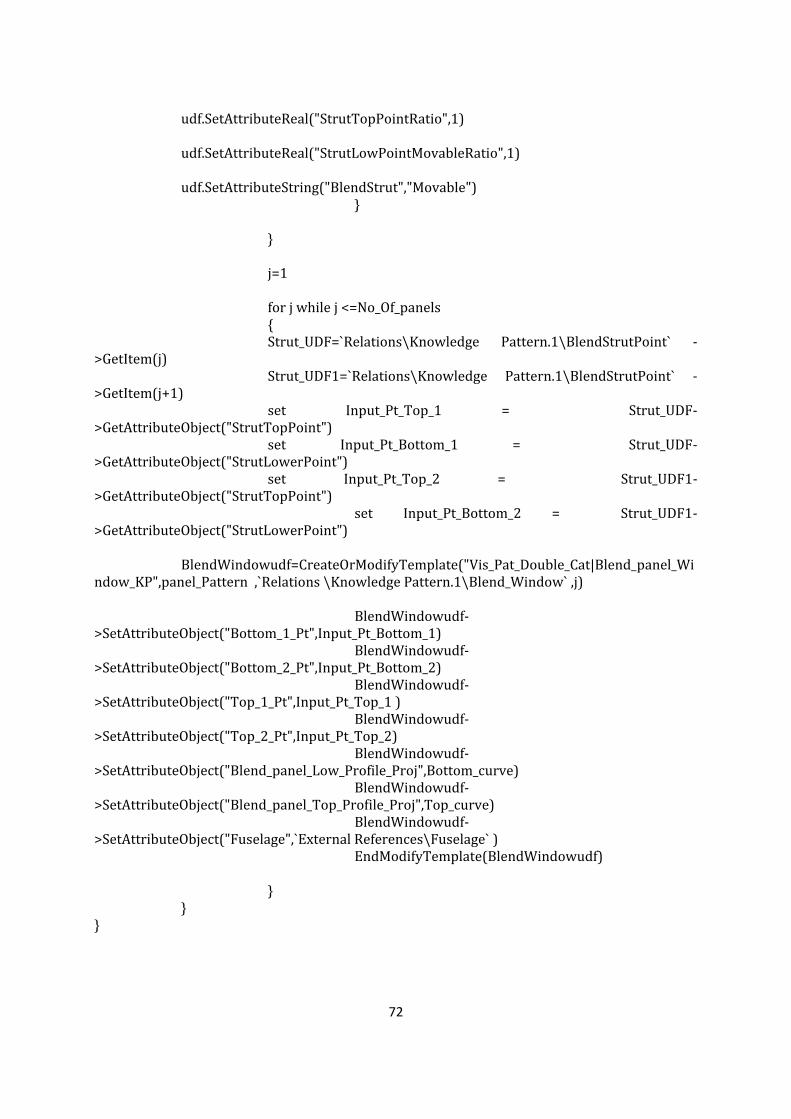
72
udf.SetAttributeReal("StrutTopPointRatio",1) udf.SetAttributeReal("StrutLowPointMovableRatio",1) udf.SetAttributeString("BlendStrut","Movable") } } j=1 for j while j <=No_Of_panels { Strut_UDF=`Relations\Knowledge Pattern.1\BlendStrutPoint` ->GetItem(j) Strut_UDF1=`Relations\Knowledge Pattern.1\BlendStrutPoint` ->GetItem(j+1) set Input_Pt_Top_1 = Strut_UDF->GetAttributeObject("StrutTopPoint") set Input_Pt_Bottom_1 = Strut_UDF->GetAttributeObject("StrutLowerPoint") set Input_Pt_Top_2 = Strut_UDF1->GetAttributeObject("StrutTopPoint") set Input_Pt_Bottom_2 = Strut_UDF1->GetAttributeObject("StrutLowerPoint") BlendWindowudf=CreateOrModifyTemplate("Vis_Pat_Double_Cat|Blend_panel_Window_KP",panel_Pattern ,`Relations \Knowledge Pattern.1\Blend_Window` ,j) BlendWindowudf->SetAttributeObject("Bottom_1_Pt",Input_Pt_Bottom_1) BlendWindowudf->SetAttributeObject("Bottom_2_Pt",Input_Pt_Bottom_2) BlendWindowudf->SetAttributeObject("Top_1_Pt",Input_Pt_Top_1 ) BlendWindowudf->SetAttributeObject("Top_2_Pt",Input_Pt_Top_2) BlendWindowudf->SetAttributeObject("Blend_panel_Low_Profile_Proj",Bottom_curve) BlendWindowudf->SetAttributeObject("Blend_panel_Top_Profile_Proj",Top_curve) BlendWindowudf->SetAttributeObject("Fuselage",`External References\Fuselage` ) EndModifyTemplate(BlendWindowudf) } } }

73

74
B- Appendix - VB
B.1 Fairng-VB-1
Set prodActDocument = CATIA.ActiveDocument Set AssemblyProduct = prodActDocument.Product Set AssemblyProducts = AssemblyProduct.Products Set AssemblyParameters = AssemblyProduct.Parameters Set AssemblyRelations = AssemblyProduct.Relations Set obj = prodActDocument.Selection Set prod_Docs = CATIA.Documents Set fuse_Part_item = prod_Docs.Item("Fuselage.CATPart") Set Fuselage_Part = fuse_Part_item.Part Set fuse_part_HBS = Fuselage_Part.HybridBodies Set fuse_part_HB = fuse_part_HBS.Item("External References") Set fuse_part_GS = fuse_part_HBS.Item("Fuselage.1") Set fuse_part_GHS = fuse_part_GS.Hybridshapes Set fuse_para = Fuselage_Part.Parameters Set fuse_part_rel = Fuselage_Part.Relations Set fuse_part_HSF = Fuselage_Part.HybridShapeFactory Set Wing_part_item = AssemblyProducts.Item("MAIN_WING") Set Wing_Prod = Wing_part_item.Products Set Wing_MDF = prod_Docs.Item("MDF_WING.CATPart") Set Wing_MDF_part = Wing_MDF.Part Set Wing_MDF_HBS = Wing_MDF_part.HybridBodies Set Wing_MDF_GS = Wing_MDF_HBS.Item("MDF_WING_GS") Set Wing_MDF_GHS = Wing_MDF_GS.Hybridshapes Set Wing_MDF_para = Wing_MDF_part.Parameters Set Wing_MDF_Relations = Wing_MDF_part.Relations Set WING_MDF_part_HSF = Wing_MDF_part.HybridShapeFactory Set Wing_MDS = prod_Docs.Item("MDS_WING.CATPart") Set Wing_MDS_part = Wing_MDS.Part Set Wing_MDS_HBS = Wing_MDS_part.HybridBodies Set Wing_MDS_HB = Wing_MDS_HBS.Item("External References") Set Wing_MDS_GS = Wing_MDS_HBS.Item("MDS_WING_GS") Set Wing_MDS_GHS = Wing_MDS_GS.Hybridshapes Set Wing_MDS_para = Wing_MDS_part.Parameters Set Wing_MDS_Relations = Wing_MDS_part.Relations Set fuse_MDS_part_HSF = Wing_MDS_part.HybridShapeFactory Set New_Fairing = AssemblyParameters.Item("wing_pos") Set Status_para = AssemblyParameters.Item("Status") Set Auto_Para = AssemblyParameters.Item("TypeOfAutomation") Set Fairing_Part_item = prod_Docs.Item("MainFairing.CATPart") Set Fairing_Part = Fairing_Part_item.Part Set Fairing_Part_HBS = Fairing_Part.HybridBodies Set Fairing_Part_HB = Fairing_Part_HBS.Item("External References") Set Fairing_para = Fuselage_Part.Parameters Set Fairing_part_rel = Fairing_Part.Relations Set Fairing_part_HSF = Fairing_Part.HybridShapeFactory Set Fairing_EX_HS = Fairing_Part_HB.Hybridshapes Set prodActDocument = CATIA.ActiveDocument
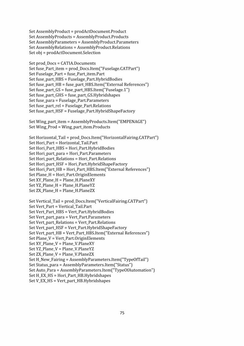
75
Set AssemblyProduct = prodActDocument.Product Set AssemblyProducts = AssemblyProduct.Products Set AssemblyParameters = AssemblyProduct.Parameters Set AssemblyRelations = AssemblyProduct.Relations Set obj = prodActDocument.Selection Set prod_Docs = CATIA.Documents Set fuse_Part_item = prod_Docs.Item("Fuselage.CATPart") Set Fuselage_Part = fuse_Part_item.Part Set fuse_part_HBS = Fuselage_Part.HybridBodies Set fuse_part_HB = fuse_part_HBS.Item("External References") Set fuse_part_GS = fuse_part_HBS.Item("Fuselage.1") Set fuse_part_GHS = fuse_part_GS.Hybridshapes Set fuse_para = Fuselage_Part.Parameters Set fuse_part_rel = Fuselage_Part.Relations Set fuse_part_HSF = Fuselage_Part.HybridShapeFactory Set Wing_part_item = AssemblyProducts.Item("EMPENAGE") Set Wing_Prod = Wing_part_item.Products Set Horizontal_Tail = prod_Docs.Item("HorizontalFairing.CATPart") Set Hori_Part = Horizontal_Tail.Part Set Hori_Part_HBS = Hori_Part.HybridBodies Set Hori_part_para = Hori_Part.Parameters Set Hori_part_Relations = Hori_Part.Relations Set Hori_part_HSF = Hori_Part.HybridShapeFactory Set Hori_Part_HB = Hori_Part_HBS.Item("External References") Set Plane_H = Hori_Part.OriginElements Set XY_Plane_H = Plane_H.PlaneXY Set YZ_Plane_H = Plane_H.PlaneYZ Set ZX_Plane_H = Plane_H.PlaneZX Set Vertical_Tail = prod_Docs.Item("VerticalFairing.CATPart") Set Vert_Part = Vertical_Tail.Part Set Vert_Part_HBS = Vert_Part.HybridBodies Set Vert_part_para = Vert_Part.Parameters Set Vert_part_Relations = Vert_Part.Relations Set Vert_part_HSF = Vert_Part.HybridShapeFactory Set Vert_part_HB = Vert_Part_HBS.Item("External References") Set Plane_V = Vert_Part.OriginElements Set XY_Plane_V = Plane_V.PlaneXY Set YZ_Plane_V = Plane_V.PlaneYZ Set ZX_Plane_V = Plane_V.PlaneZX Set H_New_Fairing = AssemblyParameters.Item("TypeOfTail") Set Status_para = AssemblyParameters.Item("Status") Set Auto_Para = AssemblyParameters.Item("TypeOfAutomation") Set H_EX_HS = Hori_Part_HB.Hybridshapes Set V_EX_HS = Vert_part_HB.Hybridshapes

76
B.2 Fairing-VB-2
AssemblyProduct.Update If Auto_Para.Value = "VB" Then If Status_para.Value = "Start" Then Set Newfairing_Geoset = Fairing_Part_HBS.Add() Newfairing_Geoset.Name = "VB" ElseIf Status_para.Value = "InProcess" Then Set selection_del = prodActDocument.Selection Set Del_F_HB = Fairing_Part_HBS.Item("VB") Set Del_F_Para = Fairing_Part.Parameters Set Del_F_RootPara = Del_F_Para.RootParameterSet obj.Clear obj.Add Del_F_HB obj.Add Del_F_RootPara obj.Delete obj.Clear Set Newfairing_Geoset = Fairing_Part_HBS.Add() Newfairing_Geoset.Name = "VB" End If EmpennageVB If Auto_Para.Value = "VB" Then If Status_para.Value = "Start" Then Set H_Newfairing_Geoset = Hori_Part_HBS.Add() H_Newfairing_Geoset.Name = "H_VB" Set V_Newfairing_Geoset = Vert_Part_HBS.Add() V_Newfairing_Geoset.Name = "V_VB" ElseIf Status_para.Value = "InProcess" Then 'Set Selection_H = prodActDocument.Selection Set Del_H_HB = Hori_Part_HBS.Item("H_VB") Set Del_H_Para = Hori_Part.Parameters Set Del_H_RootPara = Del_H_Para.RootParameterSet obj.Clear obj.Add Del_H_HB obj.Add Del_H_RootPara obj.Delete obj.Clear Set Newfairing_Geoset = Hori_Part_HBS.Add() Newfairing_Geoset.Name = "H_VB" Set Del_V_HB = Vert_Part_HBS.Item("V_VB") Set Del_V_Para = Vert_Part.Parameters Set Del_V_RootPara = Del_V_Para.RootParameterSet obj.Clear obj.Add Del_V_HB obj.Add Del_V_RootPara obj.Delete obj.Clear Set Newfairing_Geoset = Vert_Part_HBS.Add() Newfairing_Geoset.Name = "V_VB" End If

77
B.3 Fairing-VB-3
'**********************INSTANTIATE*************' Wing_part_item.Update If New_Fairing.Value = "HIGH" Then Path = "--------------- \HIGH_FAIRING.CATPart" ‘Path has to defined according to user’ Set Factory_HIGH = Fairing_Part.GetCustomerFactory("InstanceFactory") Factory_HIGH.BeginInstanceFactory "HIGH_FAIRING_PC", Path Factory_HIGH.BeginInstantiate AssemblyProduct.Update Factory_HIGH.PutInputData "zx plane", Fairing_EX_HS.Item("WING_ZX_REF") Factory_HIGH.PutInputData "Wing_Surface", Fairing_EX_HS.Item("Wing_Surface") Factory_HIGH.PutInputData "xy plane", Fairing_EX_HS.Item("WING_XY_REF") Factory_HIGH.PutInputData "Fuselage", Fairing_EX_HS.Item("Fuselage") Factory_HIGH.PutInputData "DIHEDRAL_ANHEDRAL_ANGLE",
Fairing_EX_HS.Item("DIHEDRAL_ANHEDRAL_ANGLE") Factory_HIGH.PutInputData "yz plane", Fairing_EX_HS.Item("WING_YZ_REF") Set Instance = Factory_HIGH.Instantiate Factory_HIGH.EndInstantiate Factory_HIGH.EndInstanceFactory Fairing_Part.Update ElseIf New_Fairing.Value = "MID" Then Set Factory_MID = Fairing_Part.GetCustomerFactory("InstanceFactory") Path = "--------------- \HIGH_FAIRING.CATPart" ‘Path has to defined according to user’ Factory_MID.BeginInstanceFactory "MID_FAIRING_PC", "Path \MID_FAIRING.CATPart" Factory_MID.BeginInstantiate AssemblyProduct.Update Factory_MID.PutInputData "zx plane", Fairing_EX_HS.Item("WING_ZX_REF") Factory_MID.PutInputData "Wing_Surface", Fairing_EX_HS.Item("Wing_Surface") Factory_MID.PutInputData "xy plane", Fairing_EX_HS.Item("WING_XY_REF") Factory_MID.PutInputData "Fuselage", Fairing_EX_HS.Item("Fuselage") Factory_MID.PutInputData "WING_POS", Fairing_EX_HS.Item("WING_POS") Factory_MID.PutInputData "DIHEDRAL_ANHEDRAL_ANGLE",
Fairing_EX_HS.Item("DIHEDRAL_ANHEDRAL_ANGLE") Factory_MID.PutInputData "yz plane", Fairing_EX_HS.Item("WING_YZ_REF") Factory_MID.PutInputData "TrailingEdgeLine", Fairing_EX_HS.Item("TrailingEdgeLine") Set Instance = Factory_MID.Instantiate Factory_MID.EndInstantiate Factory_MID.EndInstanceFactory Fairing_Part.Update ElseIf New_Fairing.Value = "LOW" Then Set Factory_LOW = Fairing_Part.GetCustomerFactory("InstanceFactory") Path = "--------------- \HIGH_FAIRING.CATPart" ‘Path has to defined according to user’ Factory_LOW.BeginInstanceFactory "LOW_FAIRING_PC", "Path \LOW_FAIRING.CATPart" Factory_LOW.BeginInstantiate AssemblyProduct.Update Factory_LOW.PutInputData "zx plane", Fairing_EX_HS.Item("WING_ZX_REF") Factory_LOW.PutInputData "Wing_Surface", Fairing_EX_HS.Item("Wing_Surface") Factory_LOW.PutInputData "xy plane", Fairing_EX_HS.Item("WING_XY_REF") Factory_LOW.PutInputData "Fuselage", Fairing_EX_HS.Item("Fuselage") Factory_LOW.PutInputData "WING_POS", Fairing_EX_HS.Item("WING_POS")
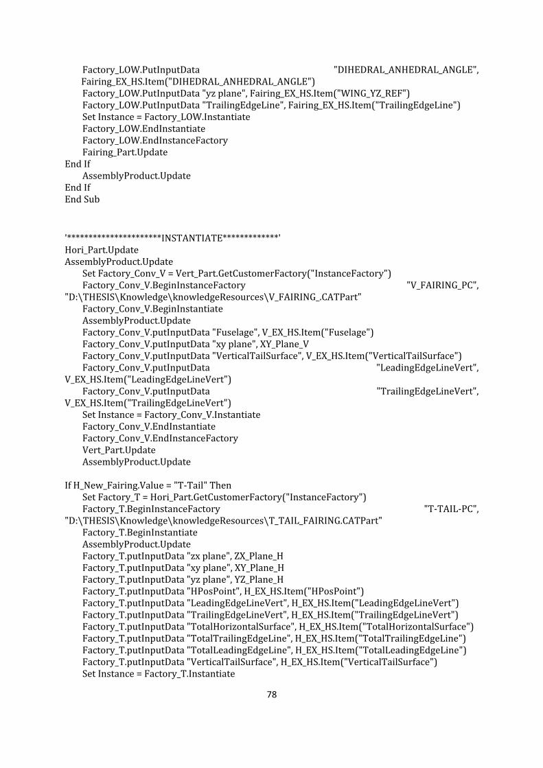
78
Factory_LOW.PutInputData "DIHEDRAL_ANHEDRAL_ANGLE", Fairing_EX_HS.Item("DIHEDRAL_ANHEDRAL_ANGLE")
Factory_LOW.PutInputData "yz plane", Fairing_EX_HS.Item("WING_YZ_REF") Factory_LOW.PutInputData "TrailingEdgeLine", Fairing_EX_HS.Item("TrailingEdgeLine") Set Instance = Factory_LOW.Instantiate Factory_LOW.EndInstantiate Factory_LOW.EndInstanceFactory Fairing_Part.Update End If AssemblyProduct.Update End If End Sub
'**********************INSTANTIATE*************' Hori_Part.Update AssemblyProduct.Update Set Factory_Conv_V = Vert_Part.GetCustomerFactory("InstanceFactory") Factory_Conv_V.BeginInstanceFactory "V_FAIRING_PC", "D:\THESIS\Knowledge\knowledgeResources\V_FAIRING_.CATPart" Factory_Conv_V.BeginInstantiate AssemblyProduct.Update Factory_Conv_V.putInputData "Fuselage", V_EX_HS.Item("Fuselage") Factory_Conv_V.putInputData "xy plane", XY_Plane_V Factory_Conv_V.putInputData "VerticalTailSurface", V_EX_HS.Item("VerticalTailSurface") Factory_Conv_V.putInputData "LeadingEdgeLineVert", V_EX_HS.Item("LeadingEdgeLineVert") Factory_Conv_V.putInputData "TrailingEdgeLineVert", V_EX_HS.Item("TrailingEdgeLineVert") Set Instance = Factory_Conv_V.Instantiate Factory_Conv_V.EndInstantiate Factory_Conv_V.EndInstanceFactory Vert_Part.Update AssemblyProduct.Update If H_New_Fairing.Value = "T-Tail" Then Set Factory_T = Hori_Part.GetCustomerFactory("InstanceFactory") Factory_T.BeginInstanceFactory "T-TAIL-PC", "D:\THESIS\Knowledge\knowledgeResources\T_TAIL_FAIRING.CATPart" Factory_T.BeginInstantiate AssemblyProduct.Update Factory_T.putInputData "zx plane", ZX_Plane_H Factory_T.putInputData "xy plane", XY_Plane_H Factory_T.putInputData "yz plane", YZ_Plane_H Factory_T.putInputData "HPosPoint", H_EX_HS.Item("HPosPoint") Factory_T.putInputData "LeadingEdgeLineVert", H_EX_HS.Item("LeadingEdgeLineVert") Factory_T.putInputData "TrailingEdgeLineVert", H_EX_HS.Item("TrailingEdgeLineVert") Factory_T.putInputData "TotalHorizontalSurface", H_EX_HS.Item("TotalHorizontalSurface") Factory_T.putInputData "TotalTrailingEdgeLine", H_EX_HS.Item("TotalTrailingEdgeLine") Factory_T.putInputData "TotalLeadingEdgeLine", H_EX_HS.Item("TotalLeadingEdgeLine") Factory_T.putInputData "VerticalTailSurface", H_EX_HS.Item("VerticalTailSurface") Set Instance = Factory_T.Instantiate
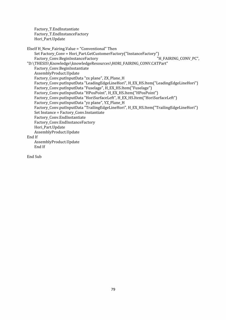
79
Factory_T.EndInstantiate Factory_T.EndInstanceFactory Hori_Part.Update ElseIf H_New_Fairing.Value = "Conventional" Then Set Factory_Conv = Hori_Part.GetCustomerFactory("InstanceFactory") Factory_Conv.BeginInstanceFactory "H_FAIRING_CONV_PC", "D:\THESIS\Knowledge\knowledgeResources\HORI_FAIRING_CONV.CATPart" Factory_Conv.BeginInstantiate AssemblyProduct.Update Factory_Conv.putInputData "zx plane", ZX_Plane_H Factory_Conv.putInputData "LeadingEdgeLineHori", H_EX_HS.Item("LeadingEdgeLineHori") Factory_Conv.putInputData "Fuselage", H_EX_HS.Item("Fuselage") Factory_Conv.putInputData "HPosPoint", H_EX_HS.Item("HPosPoint") Factory_Conv.putInputData "HoriSurfaceLeft", H_EX_HS.Item("HoriSurfaceLeft") Factory_Conv.putInputData "yz plane", YZ_Plane_H Factory_Conv.putInputData "TrailingEdgeLineHori", H_EX_HS.Item("TrailingEdgeLineHori") Set Instance = Factory_Conv.Instantiate Factory_Conv.EndInstantiate Factory_Conv.EndInstanceFactory Hori_Part.Update AssemblyProduct.Update End If AssemblyProduct.Update End If End Sub
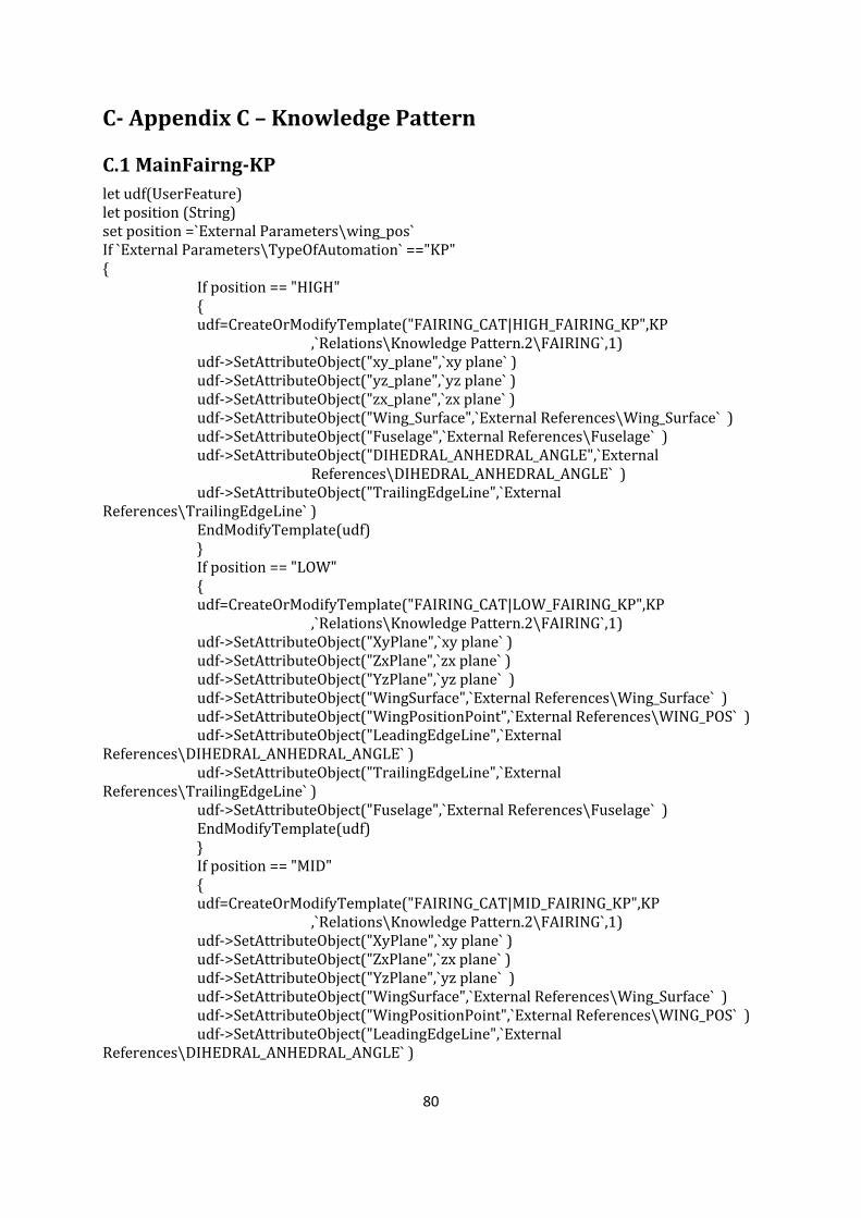
80
C- Appendix C – Knowledge Pattern
C.1 MainFairng-KP
let udf(UserFeature) let position (String) set position =`External Parameters\wing_pos` If `External Parameters\TypeOfAutomation` =="KP" { If position == "HIGH" {
udf=CreateOrModifyTemplate("FAIRING_CAT|HIGH_FAIRING_KP",KP ,`Relations\Knowledge Pattern.2\FAIRING`,1)
udf->SetAttributeObject("xy_plane",`xy plane` ) udf->SetAttributeObject("yz_plane",`yz plane` ) udf->SetAttributeObject("zx_plane",`zx plane` ) udf->SetAttributeObject("Wing_Surface",`External References\Wing_Surface` ) udf->SetAttributeObject("Fuselage",`External References\Fuselage` )
udf->SetAttributeObject("DIHEDRAL_ANHEDRAL_ANGLE",`External References\DIHEDRAL_ANHEDRAL_ANGLE` )
udf->SetAttributeObject("TrailingEdgeLine",`External References\TrailingEdgeLine` ) EndModifyTemplate(udf) } If position == "LOW" {
udf=CreateOrModifyTemplate("FAIRING_CAT|LOW_FAIRING_KP",KP ,`Relations\Knowledge Pattern.2\FAIRING`,1)
udf->SetAttributeObject("XyPlane",`xy plane` ) udf->SetAttributeObject("ZxPlane",`zx plane` ) udf->SetAttributeObject("YzPlane",`yz plane` ) udf->SetAttributeObject("WingSurface",`External References\Wing_Surface` ) udf->SetAttributeObject("WingPositionPoint",`External References\WING_POS` ) udf->SetAttributeObject("LeadingEdgeLine",`External References\DIHEDRAL_ANHEDRAL_ANGLE` ) udf->SetAttributeObject("TrailingEdgeLine",`External References\TrailingEdgeLine` ) udf->SetAttributeObject("Fuselage",`External References\Fuselage` ) EndModifyTemplate(udf) } If position == "MID" {
udf=CreateOrModifyTemplate("FAIRING_CAT|MID_FAIRING_KP",KP ,`Relations\Knowledge Pattern.2\FAIRING`,1)
udf->SetAttributeObject("XyPlane",`xy plane` ) udf->SetAttributeObject("ZxPlane",`zx plane` ) udf->SetAttributeObject("YzPlane",`yz plane` ) udf->SetAttributeObject("WingSurface",`External References\Wing_Surface` ) udf->SetAttributeObject("WingPositionPoint",`External References\WING_POS` ) udf->SetAttributeObject("LeadingEdgeLine",`External References\DIHEDRAL_ANHEDRAL_ANGLE` )

81
udf->SetAttributeObject("TrailingEdgeLine",`External References\TrailingEdgeLine` ) udf->SetAttributeObject("Fuselage",`External References\Fuselage` ) EndModifyTemplate(udf) } }
C.2 Horizontal Tail – KP
let udf(UserFeature) let position (String) set position =`External Parameters\Type of h_tail` If `External Parameters\TypeOfAutomation` =="KP" { If position == "Conventional" { udf=CreateOrModifyTemplate("EmpenageFairing_CAT|H_FAIRING_CONV_KP",KP ,`Relations\Knowledge Pattern.1\Horizontal_fairing` ,1) udf->SetAttributeObject("YzPlane",`yz plane` ) udf->SetAttributeObject("ZxPlane",`zx plane` ) udf->SetAttributeObject("Fuselage",`External References\Fuselage` ) udf->SetAttributeObject("HoriSurfaceLeft",`External References\HoriSurfaceLeft` ) udf->SetAttributeObject("HPosPoint",`External References\HPosPoint` )
udf->SetAttributeObject("LeadingEdgeLineHori",`External References\LeadingEdgeLineHori` )
udf->SetAttributeObject("TrailingEdgeLineHori",`External References\TrailingEdgeLineHori` )
EndModifyTemplate(udf) } If position == "T-Tail" {
udf=CreateOrModifyTemplate("EmpenageFairing_CAT|KP_HORI_T",KP ,`Relations\Knowledge Pattern.1\Horizontal_fairing`,1)
udf->SetAttributeObject("YzPlane",`yz plane` ) udf->SetAttributeObject("ZxPlane",`zx plane` ) udf->SetAttributeObject("XyPlane",`xy plane` )
udf->SetAttributeObject("VerticalTailSurface",`External References\VerticalTailSurface` )
udf->SetAttributeObject("TotalHorizontalSurface",`External References\TotalHorizontalSurface` )
udf->SetAttributeObject("HPosPoint",`External References\HPosPoint` ) udf->SetAttributeObject("TotalLeadingEdgeLine",`External
References\TotalLeadingEdgeLine` ) udf->SetAttributeObject("TotalTrailingEdgeLine",`External
References\TotalTrailingEdgeLine` ) udf->SetAttributeObject("LeadingEdgeLineVert",`External
References\LeadingEdgeLineVert` ) udf->SetAttributeObject("TrailingEdgeLineVert",`External
References\TrailingEdgeLineVert` ) EndModifyTemplate(udf)
}
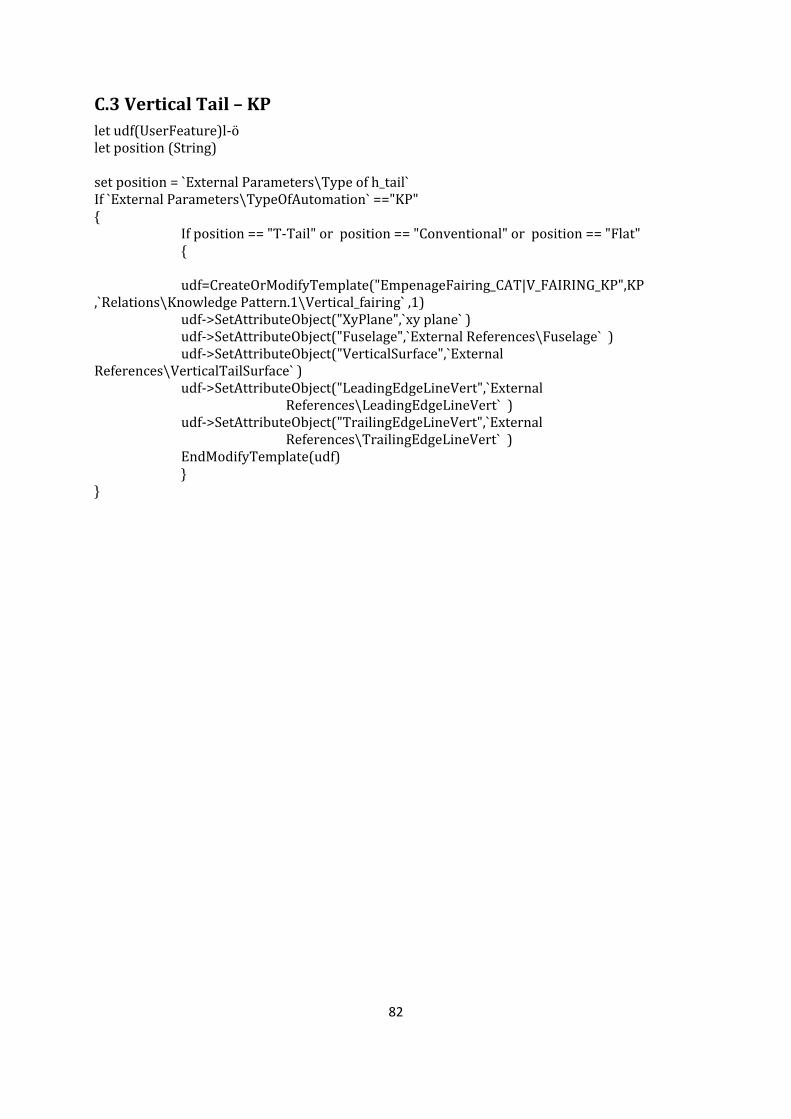
82
C.3 Vertical Tail – KP
let udf(UserFeature)l-ö let position (String) set position = `External Parameters\Type of h_tail` If `External Parameters\TypeOfAutomation` =="KP" { If position == "T-Tail" or position == "Conventional" or position == "Flat" { udf=CreateOrModifyTemplate("EmpenageFairing_CAT|V_FAIRING_KP",KP ,`Relations\Knowledge Pattern.1\Vertical_fairing` ,1) udf->SetAttributeObject("XyPlane",`xy plane` ) udf->SetAttributeObject("Fuselage",`External References\Fuselage` ) udf->SetAttributeObject("VerticalSurface",`External References\VerticalTailSurface` )
udf->SetAttributeObject("LeadingEdgeLineVert",`External References\LeadingEdgeLineVert` )
udf->SetAttributeObject("TrailingEdgeLineVert",`External References\TrailingEdgeLineVert` )
EndModifyTemplate(udf) } }
Related Documents
![ON THE PARAMETERIZED COMPLEXITY OF APPROXIMATE …matematicas.uis.edu.co/.../files/p-approx-counting.pdf · 1.1. Parameterized Complexity. Parameterized complexity theory [5], [3]](https://static.cupdf.com/doc/110x72/5fa9b6c0f3b3624d395da859/on-the-parameterized-complexity-of-approximate-11-parameterized-complexity-parameterized.jpg)