Formal Methods in System Design, 16, 59–91 (2000) c 2000 Kluwer Academic Publishers. Manufactured in The Netherlands. Automated Correctness Condition Generation for Formal Verification of Synthesized RTL Designs * NAZANIN MANSOURI [email protected] RANGA VEMURI [email protected] Digital Design Environments Laboratory, ECECS Department, University of Cincinnati, Cincinnati, Ohio 45221-0030, USA Abstract. High-level synthesis tools generate register-transfer level designs from algorithmic behavioral speci- fications. The high-level synthesis process typically consists of dependency graph scheduling, functional unit allocation, register allocation, interconnect allocation and controller generation tasks. Widely used algorithms for these tasks retain the overall control flow structure of the behavioral specification allowing code motion only within basic blocks. Further, high-level synthesis algorithms are oblivious to the mathematical properties of arithmetic and logic operators. Selecting and sharing of RTL library modules are solely based on matching uninterpreted function symbols and constants. Many researchers have noted that these features of high-level synthesis algorithms can be exploited to develop efficient verification strategies for synthesized designs. This paper reports a verification technique that effectively exploits these features to achieve efficient and fully automated verification of synthesized designs and its incorporation in a high-level synthesis tool. In our technique, a correctness condition generator is tightly integrated with a high-level synthesis tool to automatically generate (1) formal specifications of the behavior and the RTL design including the data path and the controller, (2) the correctness lemmas establishing equivalence between the synthesized RTL design and its behavioral specification, and (3) their proof scripts that can be submitted to a higher-order logic proof checker without further human interaction. This approach is based on the identification, by the synthesis tool during the synthesis process, of the binding between critical specification variables and critical registers in the RTL design, and between the critical states in the behavior and the corresponding states in the RTL design. We have implemented our verification technique in conjunction with a relatively mature high-level synthesis tool. We report experimental results indicating the effectiveness of the proposed technique and summarize our ongoing work to further strengthen it. Keywords: correctness conditions, high-level synthesis, RT-level verification, formal synthesis, theorem proving 1. Introduction High-level synthesis (HLS) systems generate register-transfer level (RTL) designs from algorithmic behavioral specifications (figure 1) [8, 15, 19, 26, 48, 53]. The RTL design consists of a data path and a controller. The data path consists of component instances selected from an RTL component library. The controller is a finite-state machine (FSM) description subject to down-stream FSM synthesis. High-level synthesis process begins by compiling the behavior specification into a control-data flow graph (CDFG) representation. The CDFG typically consists of operator nodes representing the arithmetic and logical * This paper is an extension to the work presented in the International Conference on Formal Methods in Computer Aided Design [29], Nov. 1998; also available at http://www.ececs.uc.edu/∼ddel.

Welcome message from author
This document is posted to help you gain knowledge. Please leave a comment to let me know what you think about it! Share it to your friends and learn new things together.
Transcript
Formal Methods in System Design, 16, 59–91 (2000)c© 2000 Kluwer Academic Publishers. Manufactured in The Netherlands.
Automated Correctness Condition Generationfor Formal Verification of Synthesized RTL Designs∗NAZANIN MANSOURI [email protected] VEMURI [email protected] Design Environments Laboratory, ECECS Department, University of Cincinnati, Cincinnati,Ohio 45221-0030, USA
Abstract. High-level synthesis tools generate register-transfer level designs from algorithmic behavioral speci-fications. The high-level synthesis process typically consists of dependency graph scheduling, functional unitallocation, register allocation, interconnect allocation and controller generation tasks. Widely used algorithms forthese tasks retain the overall control flow structure of the behavioral specification allowing code motion only withinbasic blocks. Further, high-level synthesis algorithms are oblivious to the mathematical properties of arithmeticand logic operators. Selecting and sharing of RTL library modules are solely based on matching uninterpretedfunction symbols and constants. Many researchers have noted that these features of high-level synthesis algorithmscan be exploited to develop efficient verification strategies for synthesized designs. This paper reports a verificationtechnique that effectively exploits these features to achieve efficient and fully automated verification of synthesizeddesigns and its incorporation in a high-level synthesis tool.
In our technique, a correctness condition generator is tightly integrated with a high-level synthesis tool toautomatically generate (1) formal specifications of the behavior and the RTL design including the data path andthe controller, (2) the correctness lemmas establishing equivalence between the synthesized RTL design and itsbehavioral specification, and (3) their proof scripts that can be submitted to a higher-order logic proof checkerwithout further human interaction. This approach is based on the identification, by the synthesis tool during thesynthesis process, of the binding between critical specification variables and critical registers in the RTL design,and between the critical states in the behavior and the corresponding states in the RTL design.
We have implemented our verification technique in conjunction with a relatively mature high-level synthesistool. We report experimental results indicating the effectiveness of the proposed technique and summarize ourongoing work to further strengthen it.
Keywords: correctness conditions, high-level synthesis, RT-level verification, formal synthesis, theorem proving
1. Introduction
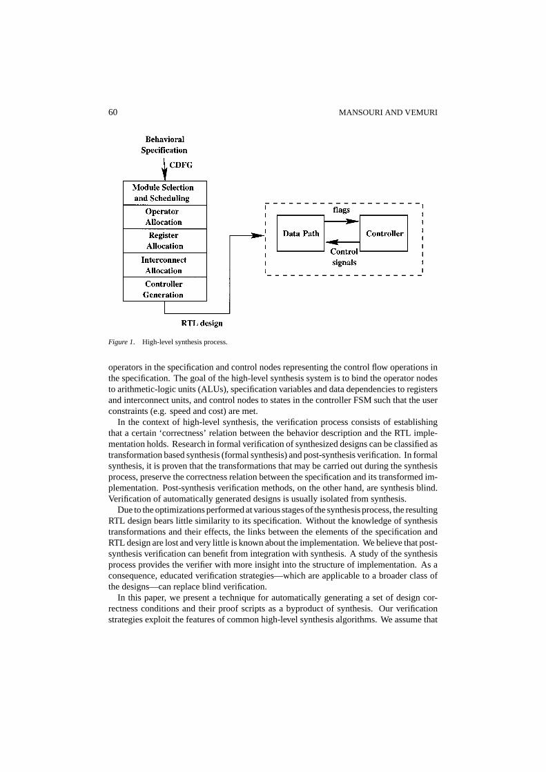
High-level synthesis (HLS) systems generate register-transfer level (RTL) designs fromalgorithmic behavioral specifications (figure 1) [8, 15, 19, 26, 48, 53]. The RTL designconsists of a data path and a controller. The data path consists of component instancesselected from an RTL component library. The controller is a finite-state machine (FSM)description subject to down-stream FSM synthesis. High-level synthesis process begins bycompiling the behavior specification into a control-data flow graph (CDFG) representation.The CDFG typically consists of operator nodes representing the arithmetic and logical
∗This paper is an extension to the work presented in the International Conference on Formal Methods in ComputerAided Design [29], Nov. 1998; also available at http://www.ececs.uc.edu/∼ddel.
60 MANSOURI AND VEMURI
Figure 1. High-level synthesis process.
operators in the specification and control nodes representing the control flow operations inthe specification. The goal of the high-level synthesis system is to bind the operator nodesto arithmetic-logic units (ALUs), specification variables and data dependencies to registersand interconnect units, and control nodes to states in the controller FSM such that the userconstraints (e.g. speed and cost) are met.
In the context of high-level synthesis, the verification process consists of establishingthat a certain ‘correctness’ relation between the behavior description and the RTL imple-mentation holds. Research in formal verification of synthesized designs can be classified astransformation based synthesis (formal synthesis) and post-synthesis verification. In formalsynthesis, it is proven that the transformations that may be carried out during the synthesisprocess, preserve the correctness relation between the specification and its transformed im-plementation. Post-synthesis verification methods, on the other hand, are synthesis blind.Verification of automatically generated designs is usually isolated from synthesis.
Due to the optimizations performed at various stages of the synthesis process, the resultingRTL design bears little similarity to its specification. Without the knowledge of synthesistransformations and their effects, the links between the elements of the specification andRTL design are lost and very little is known about the implementation. We believe that post-synthesis verification can benefit from integration with synthesis. A study of the synthesisprocess provides the verifier with more insight into the structure of implementation. As aconsequence, educated verification strategies—which are applicable to a broader class ofthe designs—can replace blind verification.
In this paper, we present a technique for automatically generating a set of design cor-rectness conditions and their proof scripts as a byproduct of synthesis. Our verificationstrategies exploit the features of common high-level synthesis algorithms. We assume that

AUTOMATED CORRECTNESS CONDITION GENERATION 61
the behavioral specification has been already transformed into the desired algorithmic formbefore synthesis commences. Once submitted to the synthesis system, it is not subjectedto further behavioral transformation. Two main ideas have considerably contributed to oursuccess in devising an efficient automated verification method:
— We argue that the high-level synthesis tools can easily produce information aboutbehavior-to-RTL state and variable binding that can be effectively exploited duringverification.
— Further, we show that in the verification of automatically synthesized designs, functionsand constant symbols can be left uninterpreted, leading to efficient verification basedmostly on rewriting strategies, and that the necessary rewriting steps can be automati-cally generated by making use of the variable and state binding information.
We have implemented this method in the context of a relatively mature high-level synthesissystem and verified several synthesized designs using the PVS [43] proof checker. Someof these designs are high-level synthesis benchmarks (TLC, Filter and Elliptic Filter) andthe rest are similar to these benchmarks with respect to size and complexity.
The organization of the paper is as follows: In Section 2, we review related research.In Section 3, we motivate the basis for our technique through an example, present a briefoverview of the high-level synthesis process, and informally discuss the outline of ourtechnique. In Section 4, we discuss the verification technique in a more formal setting.Section 5 is a detailed study of synthesis stages and presents discussions on how the elementsof verification are affected by the transformations of each stage. In Section 6, we presentfurther enhancements to our method, eliminating some of the assumptions made earlier.In Section 7, we present the correctness condition generator integrated with the high-level synthesis system. Section 8 discusses the implementation and experimental results.Concluding remarks and comments on ongoing work are presented in Section 9.
2. Related research
Several authors have devised techniques for verification of synthesized designs. Verificationmethods commonly used for verification of digital designs may be categorized as follows:
Transformation based or formal synthesis methods: Transformational approach to hard-ware synthesis has been pioneered by Johnson [24]. Vemuri [51] and Feldbusch andKumar [18] proposed converting RTL implementation into a normal form where it canbe compared with the behavior specification in a straight-forward manner. However,transformation into normal form seems to be possible only for restricted classes of de-signs. Rajan [39] addressed the same question using theorem proving by formalizingboth the transformations and their correctness in the PVS theorem prover. Eisnbieglerand Kumar [17] used tight integration of high-level synthesis with theorem proving toperform synthesis and verification hand-in-hand. McFarland [30] developedbehaviorexpressionsfor abstract specification of behavior and described how such expressions canbe used to examine the correctness of behavioral transformations used in the high-level
62 MANSOURI AND VEMURI
synthesis system SAW [48]. Aagaard and Leeser [1] reported a formally verified logicsynthesis tool. Kropf et al. [27] presented a formal high-level synthesis approach inwhich the target architecture, based on handshake processes, is produced using a fewbasic primitives. Proof obligations are automatically generated during the synthesis pro-cess. The approach presented in this paper has a similar goal, but aims to incorporateproof obligation generation within the context of conventional target architectures usedby traditional high-level synthesis tools. Narasimhan and Vemuri [33, 36] systemati-cally formulated the correctness properties for certain high-level synthesis stages. Theyidentified a set of assertions and invariants that should hold at various steps of high-levelsynthesis process. These invariants were inserted in the high-level synthesis tool DSS [41]to detect and isolate the errors in a specific run of the tool. Our verification techniquefollows the same goal in a different approach and is also integrated with DSS.
Post-design verification methods: Hunt [23] presented a formal specification and verifi-cation of the FM8501, a simple general purpose microprocessor. In his verificationexercise, a microcoded architecture is proved to implement an instruction-level descrip-tion of machine behavior. Srivas and Miller [44] reported the verification of AAMP5,a pipelined commercial microprocessor. They have formalized the macro-architectureand micro-architecture in the logic of the PVS theorem prover [43]. Their correctnessconditions are based on comparing the micro-architecture with the macro-architectureat visiblestates, an approach typical of processor verification efforts based on theoremproving [55]. The comparison is carried out using the rewriting strategies in PVS. Anabstraction functionthat returns the macro-state corresponding to a micro-state is definedto aid the process of comparison. In our method, the critical state binding, which maybe viewed as the inverse of the abstraction function, is automatically generated duringsynthesis. However, we have not yet applied our method to pipelined structure synthesis.These two verification exercises are conducted manually. The verified designs are farsuperior in terms of size and complexity to the automatically verifiable designs.
Devadas et al. [42] developed methods to verify equivalence between sequential ma-chines at RTL and logic levels. Their method depends on extracting state transition graphsfrom the two finite automata exploitingdon’ t careinformation. Corella et al. [14] verifiedsynthesized designs by back-annotating the specification withclockstatements accordingto the schedule. Claesen et al. [9, 10] developed a method to compare implementations atregister-transfer and switch levels against signal flow graph specifications. Their methodis based on partitioning the signal flow graph into disjoint acyclic subgraphs formed byreference signal boundaries. Then both the subgraph specification and the correspond-ing implementation fragment are symbolically simulated [5]. The resulting symbolicexpressions are compared using standard OBDD [6] techniques. The method of identi-fying critical states used in this paper is comparable to SFG partitioning. However, ourverification strategy itself is based on automatically generating axiomatic definitions ofthe behavior specification and RTL implementation and automatically generating proofscripts for theorem prover. Corella [12, 13] focussed on control flow properties by usinguninterpreted functions to represent data path elements. Burch and Dill [7] used similarideas to develop an efficient validity checker for a logic of uninterpreted functions withequality and used it to verify the control logic in pipelined microprocessors. The method
AUTOMATED CORRECTNESS CONDITION GENERATION 63
discussed in this paper also uses uninterpreted functions and constants but uses standarddecision procedures in a high-order logic theorem prover. Our method is developed inthe context of and is fully integrated with a high-level synthesis system so that all for-mal models, correctness conditions and proof scripts are automatically generated as abyproduct of the synthesis process. Aagaard et al. [2] attempted hardware verificationwith smart tactics. They discovered that in doing hardware proofs, the user follows thesame reasoning repeatedly and aimed to capture this reasoning. The verification systemdiscussed in this paper uses the information generated by synthesis tool for generatingthe verification tactics. It is similar to the smart tactics method in that (1) it supports hard-ware verification that is used in higher order logic theorem proving, and (2) automates therepetitive reasoning found in hardware proofs. It is different from smart tactics in that (1)verification using smart tactics requires some interaction with the user, while our proofsare carried out with no user interaction; (2) as part of the proof, smart tactics methodmaps the design correctness goals into a set of simpler subgoals, but we decompose themain correctness goal into a set of sub-lemmas that are proved independently; and (3)our verification system tailors the proof for each individual design and can always provethe correctness of a design (if a proof exist), but this is not the case with smart tactics.Windley [54] presented an engineering methodology for verifying microprocessor de-signs and proposed the integration of verification tools with CAD tools as the next stepin research. The work presented in this paper conforms with this idea.
Symbolic simulation methods: Moore [32] discussed symbolic simulation of formally spec-ified systems. He suggested that with a symbolic simulation capability, an engineer can‘run’ a design on certain kinds of indeterminant data, thereby covering more cases withone test. He used the ACL2 theorem prover for formally specifying the designs in hisexperiments. Also, in [22] Greve described how symbolic simulation was applied in thedevelopment of JEM1, the world’s first JAVA processor. In his experiments on the appli-cation of formal methods to the verification of microcoded microprocessors he discoveredthat many of the errors that were ultimately detected in formal models were revealed dur-ing the symbolic simulation of the microcode, rather than during equivalence checkingwith an abstract specification. PVS is used for the specification of JEM1. Rajan et al. [40]studied various issues in combining theorem proving and symbolic simulation. They ex-perimented with specification and verification of a bounded stack at differing levels ofabstraction. They used HOL theorem proving at higher abstraction levels, and VOSSsymbolic trajectory evaluation at the switch level. Symbolic simulation is a post-designverification approach. We categorized these methods separately since they have commonfeatures. All these methods benefit from the expressive power of theorem proving forformally specifying the designs, and by taking advantage of symbolic simulation, theyautomate the proof effort.
Simulation based methods: Bergamaschi and Raje [4] defined a notion of behavior-RTLequivalence compatible with the specification’s simulation behavior. Their techniquedepends on generating additional hardware to raise a synchronization signal at the pointsof comparison. These synchronization points, calledobservable time windows, are iden-tified based on a notion of equivalent states which is very similar to the one used inthis paper. However, in contrast to Bergamaschi’s approach targeted to simulation, our
64 MANSOURI AND VEMURI
method is targeted to fully-automated formal verification. No support hardware is nec-essary in our method.
In general, all the developed methods for formal verification of correctness of synthe-sized designs take advantage of the features and limitations of the synthesis and optimiza-tion algorithms that generate design structures in a particular style. These methods mostlyresort to syntactic or symbolic comparisons avoiding the combinatorial explosion prob-lem involved in introducing more general notion of correctness based on, for example,Boolean equivalence. Our method also takes advantage of the nature of the high-levelsynthesis algorithms. In addition, our method is fully integrated with a high-level syn-thesis tool such that both the correctness theorems and their proofs are automaticallyproduced as auxiliary outcomes of the synthesis process. These proofs are then readilyprocessed by a higher-order logic proof checker.
3. Background
Motivational example
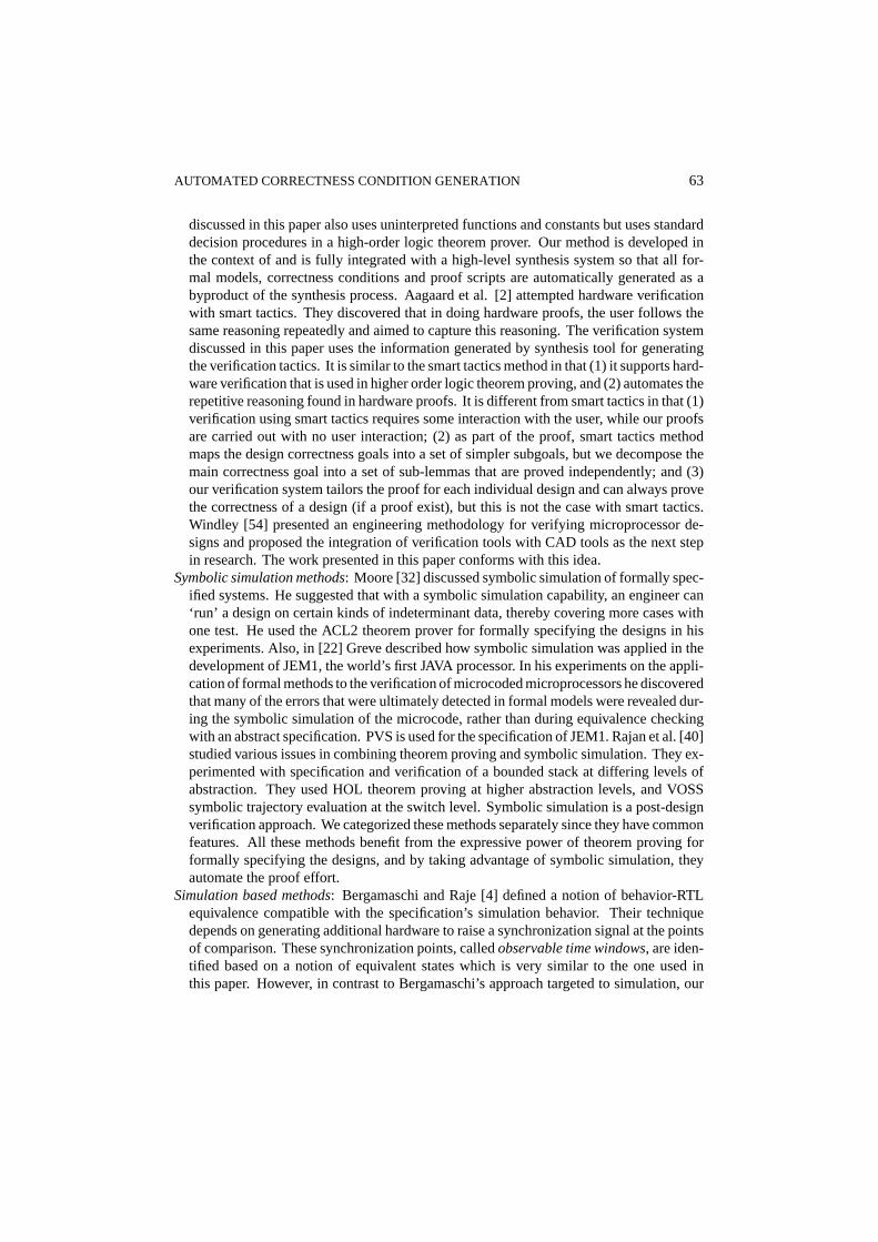
Consider the simple behavioral specification shown in figure 2(a) and its representationas abehavioral automatonin figure 2(b). The behavior automaton [46] is a finite state
Figure 2. (a) Algorithmic specification, (b) behavioral automaton.
AUTOMATED CORRECTNESS CONDITION GENERATION 65
automaton which consists of a set of states and a set of transitions among these states.There is a uniquestart state,BS0. A state may be anassignmentstate or aconditionalstate. An assignment state is annotated with one or more assignment statements and hasexactly one outgoing transition to anextstate. A conditional state is not annotated with anyassignment statements and has exactly two outgoing transitions, one of which is labeledwith the conditionv and the other is labeled with the condition¬v, wherev is a specificationvariable.1
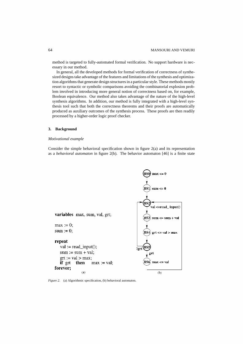
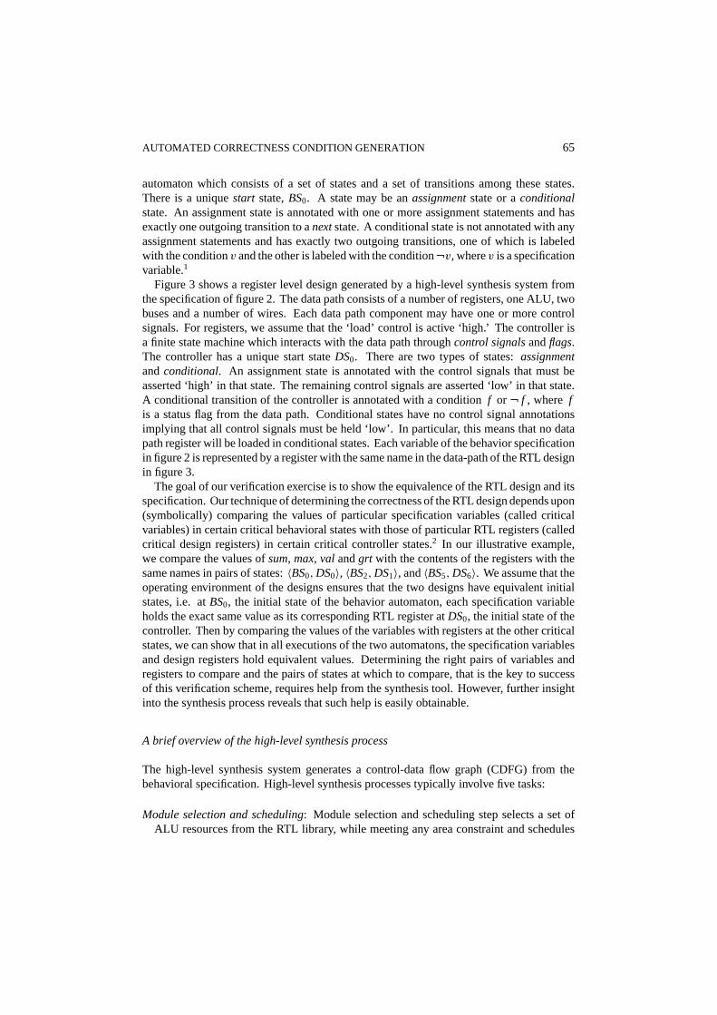
Figure 3 shows a register level design generated by a high-level synthesis system fromthe specification of figure 2. The data path consists of a number of registers, one ALU, twobuses and a number of wires. Each data path component may have one or more controlsignals. For registers, we assume that the ‘load’ control is active ‘high.’ The controller isa finite state machine which interacts with the data path throughcontrol signalsandflags.The controller has a unique start stateDS0. There are two types of states:assignmentandconditional. An assignment state is annotated with the control signals that must beasserted ‘high’ in that state. The remaining control signals are asserted ‘low’ in that state.A conditional transition of the controller is annotated with a conditionf or ¬ f , where fis a status flag from the data path. Conditional states have no control signal annotationsimplying that all control signals must be held ‘low’. In particular, this means that no datapath register will be loaded in conditional states. Each variable of the behavior specificationin figure 2 is represented by a register with the same name in the data-path of the RTL designin figure 3.
The goal of our verification exercise is to show the equivalence of the RTL design and itsspecification. Our technique of determining the correctness of the RTL design depends upon(symbolically) comparing the values of particular specification variables (called criticalvariables) in certain critical behavioral states with those of particular RTL registers (calledcritical design registers) in certain critical controller states.2 In our illustrative example,we compare the values ofsum, max, val andgrt with the contents of the registers with thesame names in pairs of states:〈BS0,DS0〉, 〈BS2,DS1〉, and〈BS5,DS6〉. We assume that theoperating environment of the designs ensures that the two designs have equivalent initialstates, i.e. atBS0, the initial state of the behavior automaton, each specification variableholds the exact same value as its corresponding RTL register atDS0, the initial state of thecontroller. Then by comparing the values of the variables with registers at the other criticalstates, we can show that in all executions of the two automatons, the specification variablesand design registers hold equivalent values. Determining the right pairs of variables andregisters to compare and the pairs of states at which to compare, that is the key to successof this verification scheme, requires help from the synthesis tool. However, further insightinto the synthesis process reveals that such help is easily obtainable.
A brief overview of the high-level synthesis process
The high-level synthesis system generates a control-data flow graph (CDFG) from thebehavioral specification. High-level synthesis processes typically involve five tasks:
Module selection and scheduling: Module selection and scheduling step selects a set ofALU resources from the RTL library, while meeting any area constraint and schedules
66 MANSOURI AND VEMURI
(a)
(b)
Figure 3. Example of an RTL design generated by a high-level synthesis system.

AUTOMATED CORRECTNESS CONDITION GENERATION 67
the CDFG across control steps such that at any control step the selected resources aresufficient to perform all the operations scheduled in that step and the clock-speed andlatency constraints, if any, are met. Scheduling may be viewed as the process of code mo-tion in compilers combined with introduction/removal of temporary variables that holdvalues across control steps. However, many high-level synthesis schedulers do not per-form code motion across conditional and iterative statement boundaries. Such behavioraltransformations (involving transforms such as constant propagation, common subexpres-sion elimination, code motion, dead-code elimination, loop unfolding, commutative andassociative rewriting of expressions, etc.) are performed prior to the commencementof scheduling in a preprocessing step calledbehavior transformation[15, 48]. Provingthe correctness of such general behavioral transformations involves techniques similarto those used in program verification. McFarland studied various behavioral transfor-mations and proposed the algebra of behavioral expressions as means to specify andverify their correctness [30].
The high-level synthesis process is then predominantly concerned with resource shar-ing. The goal of high-level synthesis is to determine constraint-satisfying sharing amongALUs, registers and interconnections. To facilitate resource-sharing, high-level synthe-sis tool performs scheduling which permits time sharing of resources whose life timesdo not overlap across the scheduled time-scale.
Scheduling process may be viewed as code motion across a time scale. Operationsmay be scheduled at any time-step as long as the data and control dependencies arenot violated. That is, if an operator is data-dependent on a source operator, it can onlybe scheduled after the source operator is scheduled. Similarly, if an operator is controldependent on a control operator then it is not scheduled until after the control operator isscheduled. Current scheduling algorithms in high-level synthesis generally assume thatcontrol operators introduce sequential control flow points into the CDFG being scheduled[8, 15, 19, 26, 48, 53]. For example, all operators inside acasestatement are scheduledonly after the deciding expression has been scheduled. All statements following thecasestatement are scheduled only after all the branches of thecasestatement are scheduled.All statements inside awhilestatement are scheduled only after the deciding expressionhas been scheduled, and all statements following thewhilestatement would be scheduledonly after the body of thewhilestatement has been scheduled. This ensures that the controlflow branches in the behavior specification are preserved and no new control flow branchesare introduced. In the simple design shown in figures 2 and 3, for example, the assignmentof the value ‘0’ to the variablesumis performed after the assignment of this value to thevariablemax; however, in the RTL design, they are scheduled at the same state. Theseoperations can be performed in any order before a transition to the stateDS1—is the borderstate of a loop—without violating any data or control dependencies. The statementscorresponding toBS3 andBS4 on the other hand, are data dependent on the statementcorresponding toBS2. They can be scheduled at any state within the border points ofthe loop, after the statement corresponding toBS2 is scheduled. Scheduling, thus, is theprocess of implicit code motion possibly involving introduction of additional temporaryvariables in order to explore the design-space to determine a constraint-satisfying time-area tradeoff point.
Functional unit allocation: Functional unit allocation is the process of binding the operatornodes of CDFG to arithmetic and logic units. High-level synthesis tools are oblivious

68 MANSOURI AND VEMURI
to the mathematical properties of the operators used in the behavioral specification. Theselection and sharing of the RTL library modules is done solely based on matchinguninterpreted function symbols and constants.
Register allocation: Register allocation involves binding both the specification variables andany temporary variables introduced during scheduling to data path registers. Typically,a compatibility graph or a conflict graph is formed following a life-time analysis of thevariables of the scheduled data flow graph. This graph is subjected to clique partitioning(for compatibility graphs) or graph coloring (for conflict graphs) to obtain a near-optimalregister allocation subject to an interconnect cost model.
Interconnect allocation: Interconnect allocation is a procedure similar to register allocationduring which buses are formed.
Controller generation: The final step in the high-level synthesis process is controller gen-eration [15]. Controller generation generates an FSM specification based on the CDFGschedule that determines the set of register-transfers to be activated in each controlstep. Typically, each control step in the CDFG is turned into an FSM state and con-trol signals are asserted in that state to activate all register transfers scheduled at step.Conditional control flow nodes in the CDFG are turned into states with conditional transi-tions. Their transition conditions are supplied from the data path in the form of conditionflags.
Operator, register and interconnect allocation algorithms, which follow the schedulingstep, are typically based on clique partitioning [50] or graph coloring [3] following life-cycle analysis of the scheduled flow graph. Operator, register and interconnect allocationalgorithms perform no code motion and do not alter the control flow. Their focus is es-sentially on resource sharing to meet cost (area) constraints.Binding refers to the finalassignment of behavioral operators, variables and data/control dependencies to RTL ALUs,registers and interconnect units. By maintaining links with the elements of the behaviorspecification throughout the high-level synthesis process (as discussed, for example, byThomas et al. [49]), the high-level synthesis tool can generate detailed binding information.Exploiting this information for verification purposes is the unique aspect of our verificationtechnique.
Outline of the method
The discussions on the scheduling process suggest that the following states in the behaviorspecification should be marked ascritical states: (1) the start state; (2) conditional states—states with more than one outgoing transition; (3) join states—states with more than oneincoming transition; (4) input states—states that read from input ports; (5) output states—states that write to output ports, and, (6) the final state (if any). These states introducecontrol flow dependencies into the CDFG and the HLS system never moves code acrossthese states. Further, since specification code between a pair of these states is subject toscheduling and hence to possible code motion during high-level synthesis, no other statescan be marked as being critical. The following variables in the behavior specification shouldbe marked ascritical variables: (1) input variables, (2) output variables, (3) any variable
AUTOMATED CORRECTNESS CONDITION GENERATION 69
that has a live value across a critical state.3 The last category of critical variables are easilyidentified during life-time analysis that precedes register allocation in high-level synthesis.The critical variables are preserved by the HLS tool and manifest in the RTL design in theform of critical registers, and the critical states in the behavior automaton are preservedby the HLS tool and manifest in the form of critical states in the controller automaton.Therefore, conditional, join, input, output and start states in the controller together form thecritical states of the controller. In our example behavior specification (figure 2),BS0, BS2
andBS5 and in its RTL implementationDS0, DS1 andDS6 are critical states. The criticalvariables of the behavior specification aremax, sum, val andgrt and their correspondingcritical registers in the data-path of RTL design areMAX, SUM, VAL andGRT.
We assume that all critical states are reachable from the start states respectively in thebehavior automaton and the RTL controller, that is, any dead-code has been eliminatedprior to high-level synthesis. Also, we assume that the operating environment of the twodesigns ensures that they start their operation from equivalent states, i.e. the initial valueof each specification variable and its corresponding RTL register are the same. Now, inorder to show that the RTL correctly implements the value transfers in the behavioralspecification, we need to symbolically show that the values in critical variables matchvalues in corresponding pairs of critical registers at the critical states, provided that theymatch at the start states. This comparison is only possible if the correspondence betweencritical variables and critical registers and between the behavioral critical states and theRTL critical states can be identified.
We can count on the high-level synthesis tool to produce such correspondences in the formof auxiliary information as a byproduct of the synthesis process. Many authors, for exampleThomas et al. [49], have described detailed methods to maintain the binding informationduring the synthesis process. We exercise our verification practice in conjunction with asynthesis tool that generates this auxiliary information. However, it can be used to verify thedesigns generated by any HLS system that can provide the required binding information. Inparticular, we require that the high-level synthesis tool can generate the mapping betweencritical variables in the specification and registers in the RTL data path and the mappingbetween the critical states in the behavior automaton and the states in the RTL controller.
Table 1a and b illustrate these two bindings, namely, (1) critical register binding, and (2)critical state binding, for the designs shown in figures 2 and 3.
Critical paths. We define acritical path in a behavioral automaton as a directed path froma critical states1 to another critical states2 without traversing through any other criticalstate.s1 is called the first or originating state of this critical path ands2 is called its last orterminating state. Since we assumed that states in the behavioral automaton have exactlyone or two outgoing transitions, there can be at most two critical paths between any pair ofcritical states. Critical paths in the RTL controller are similarly defined. Given the criticalstate binding and critical register binding functions, a third binding function namely criticalpath binding function can be defined. The critical path binding function maps a behaviorcritical path to a design critical path if: (1) the originating states of the paths are bound bythe critical state binding function, (2) the terminating states of the paths are bound by thecritical state binding function, and (3) the transition flags of the paths (if any) are bound

70 MANSOURI AND VEMURI
Table 1. Critical bindings between the behavior specification and RTL design.
(a) Critical register binding
CRb CRd
max MAXreg
sum SUMreg
val VAL reg
grt GRT reg
(b) Critical state binding
CSb CSd
BS0 DS0
BS2 DS1
BS5 DS6
(c) Critical path binding
CPb
bcp1 [BS0,BS1,BS2]
bcp2 [BS2,BS3,BS4,BS5]
bcp3 [BS5,BS2]
bcp4 [BS5,BS6,BS2]
CPd
dcp1 [DS0,DS1]
dcp2 [DS1,DS2,DS3,DS4,DS5,DS6]
dcp3 [DS6,DS1]
dcp4 [DS6,DS7,DS8,DS1]
by the critical register binding function. Table 1c shows the behavioral critical paths, RTLcritical paths and the critical path binding function for our example design.
The equivalence between a behavior specification and its RTL implementation may bedefined in terms of the equivalence of the critical paths. The RTL design is consideredcorrect if we can show that for each critical path between a pair of critical states, if thecritical variables match the critical registers at the originating states, then they will matchthem at the terminating states. This involves computation and comparison of the symbolicvalues of various critical variables and registers along corresponding pairs of critical pathsin the behavior automaton and the RTL controller. This is illustrated in Table 2 for eachcritical path in our example.
In the following section, we will present the key elements of this discussion in a moreformal setting.
Table 2. Symbolic values of the variables and regsiters at critical states.
Critical path val sum grt max
bcp1 val 0 grt 0
dcp1 val 0 grt 0
bcp2 newval sum+ newval newval> max max
dcp2 newval sum+ newval newval> max max
bcp3 val sum grt max
dcp3 val sum grt max
bcp4 val sum grt val
dcp4 val sum grt val
AUTOMATED CORRECTNESS CONDITION GENERATION 71
4. Formalization of the verification technique
Let R be the set of all registers or all variables of the design. LetCR⊆ R be the set ofcritical registers. Let Sbe the set of states in the automaton andX be the set of transitionsamong these states. LetS0be the unique start state of the automaton. LetCS⊆ S be theset of critical states. We assume that every critical state is reachable from the start state.Let CPbe the set of critical paths among these critical states. For any critical pathp ∈ CP,F(p) andL(p) denote the originating and terminating states ofp.
Then in a behavioral specification, modeled as a behavior automaton, the followingelements are defined:
Rb: the set of behavior registers or specification variablesCRb ⊆ Rb: the set ofcritical variablesSb: the set of states in the behavioral automatonXb: the set of transitions among behavior statesS0b: the unique start state of the behavioral automatonCSb ⊆ Sb: the set of critical statesCPb: the set of critical paths among critical statesFb(p): the originating state of the behavior critical pathpLb(p): the terminating state of the behavior critical pathp
Similarly, in an RTL design the following elements are defined:
Rd: the set of registers in the register level data pathCRd ⊆ Rd: the set of critical registers in the data pathSd: the set of states in the controllerXd: the set of transitions among controller statesS0d: the unique start state of the controllerCSd ⊆ Sd: the set of critical states in the controllerCPd: the set of critical paths among controller statesFd(p): the originating state of the design critical pathpLd(p): the terminating state of the design critical pathp
Following the previous discussion, we postulate that the high-level synthesis tool canproduce, as a byproduct of the synthesis process, the following two mappings (calledbindings in the synthesis terminology):
Br : CRb → CRd critical register binding
Bs : CSb → CSd critical state binding
The start state of the behavior is always mapped to the start state of the controller, that is,Bs(S0b) = S0d.
FromBs andBr we can easily derive another mappingBp : CPb→ CPd that is thecriticalpath binding. A critical pathpb ∈ CPb is mapped to critical pathpd ∈ CPd if and only iftheir originating and terminating states are mapped byBs and the transition conditions, if
72 MANSOURI AND VEMURI
any, on the outgoing transitions of their originating states match. More formally, ifv (¬v)is the condition variable annotation on the originating transition of the behavior critical pathpb, and f (¬ f ) is the condition flag of the design critical pathpd then:
Bp(pb) = pd ⇔ Bs(Fb(pb)) = Fd(pd) ∧ Bs(Lb(pb)) = Ld(pd) ∧ f = Br (v)
The propositionf = Br (v) formally states that ifpb is annotated with the conditionvariablev, then pd is annotated with the condition flagBr (v). This ensures that ifpb istraversed in the behavior,pd will be traversed in the RTL controller.
An execution pathin the behavior is a finite sequence of critical states such that the firststate in the sequence is the start state and any two successive states in the sequence form acritical path, that is:
∀eb ∈ EPb, eb = [s1, s2, . . . , si , si+1, . . .] : (s1 = S0b ∧ (∀i > 1,
∃p ∈ CPb : si = Fb(p) ∧ si+1 = Lb(p)))
WhereEPb denotes the set of all possible behavioral execution paths. Execution path inthe RTL controller is similarly defined andEPd denotes the set of all possible RTL executionpaths. We can construct an execution path binding,Be : EPb→ EPd using the critical statebinding as follows:
e= {s1, s2, . . . , si , si+1, . . .} ⇒ Be(e) = {Bs(s1), Bs(s2), . . . , Bs(si ), Bs(si+1), . . .}
wheree is an execution path in the behavior automaton, andBe(e) is its correspondingexecution path in the controller of RTL design. The last state in an execution pathe iscalled thetermination stateof e and denoted byTb(e) for the behavior automaton and byTd(e) for the RTL controller.
For the purposes of defining equivalence between the behavior and its RTL implemen-tation, we postulate an uninterpreted domain ofvalues, V. These values can be ‘stored’ inbehavioral variables as well as RTL registers. We postulate two functions for assigningvalues to critical variables and critical registers:
Vb : EPb × CRb → V
Vd : EPd × CRd → V
Vb determines the value of a critical variablerb when the behavioral automaton traversedthe execution patheb and reached the stateTb(eb). Vd is similarly defined. In the nextsection, we show axiomatic definitions ofVb andVd suitable for symbolic manipulation,automatically generated from behavioral specifications and RTL descriptions respectively.
We are now ready to define various equivalence relationships between the behavior andthe RTL design. We say that the initial stateS0b in behavior automaton is equivalent to theinitial stateS0d in the controller provided that when the two machines start operation, thevalue of each critical specification variable is the same as the content of its corresponding
AUTOMATED CORRECTNESS CONDITION GENERATION 73
critical register. Theinitial state equivalenceis denoted byS0b ≡ S0d:
S0b ≡ S0d ⇔ ∀r ∈ CRb,Vb([S0b], r ) = Vd([S0d], Br (r ))
We say that a critical states in the behavior andBs(s), its corresponding RTL criticalstate areequivalentprovided if the behavior automaton and RTL design start operationfrom equivalent initial states, and go through identical transition sequences that end ats andBs(s) respectively, then the value of each critical specification variable and the content ofits corresponding design register at these states are equivalent. We denotestate equivalenceby s≡ Bs(s):
∀s ∈ CSb : s≡ Bs(s)⇔(S0b ≡ S0d ⇒
(∀e∈ EPb, s= Tb(e), ∀r ∈ CRb :
Vb(e, r ) = Vd(Be(e), Br (r ))))
State equivalence is defined only between initial states and between the terminating statesof identical pairs of behavior-design execution paths, therefore, it is obvious thatsb ≡ sd
only if sd = Bs(sb).We say that a behavioral execution pathe is equivalentto its corresponding RTL ex-
ecution pathBe(e) provided any state of the behavior execution path is equivalent to itscorresponding state in the design execution path.Execution path equivalenceis definedonly between a behavior execution path and the design execution path to which it is boundduring the synthesis process, and is denoted bye≡ Be(e):
∀e∈ EPb : e≡ Be(e)⇔ (S0b ≡ S0d ⇒ ∀s ∈ e, s≡ Bs(s))
We say that the RTL design is equivalent to the behavior specification provided eachpossible behavior execution path is equivalent to its corresponding design execution path:
Mb ≡ Md ⇔ (∀e∈ EPb : e≡ Be(e))
Mb andMd correspond toBehavior AutomatonandDesign Automaton, respectively.We say a behavioral critical pathp is equivalent to its corresponding RTL critical path
Bp(p) provided if starting from equivalent initial states, the two critical paths terminate inequivalent states. Thecritical path equivalenceis defined only between a behavior criticalpath and the design critical path to which it is bound during the synthesis process and isdenoted byp ≡ Bp(p):
∀p ∈ CPb : p ≡ Bp(p)⇔ (Fb(p) ≡ Fd(Bp(p))⇒ Lb(p) ≡ Ld(Bp(p)))
We claim that critical path equivalence implies execution path equivalence per the fol-lowing theorem, offered here without proof:

74 MANSOURI AND VEMURI
Theorem. If every critical path in the behavior is equivalent to the RTL critical path towhich it is bound during the synthesis process, then the RTL design is equivalent to thebehavior specification. Formally:
(∀p ∈ CPb : p ≡ Bp(p))⇒ Mb ≡ Md
The proof of this statement is straight forward and follows from the original assumptionsthat the initial states of the two machines are equivalent and that in both behavioral automatonand the RTL controller, the critical states are reachable from the respective start states. Inthis proof it is shown by induction on the length of the execution paths that critical pathequivalence implies execution path equivalence, that in turn implies the equivalence of thedesigns:
∀p ∈ CPb : p ≡ Bp(p)⇒ ∀e∈ EPb : e≡ Be(e))
The above theorem is one of the key components of this paper and is the basis of ourverification technique. We verify a synthesized RTL design by proving its equivalence toits behavior specification. The equivalence of the designs is established by proving theequivalence of each critical path of the controller of the RTL design to its correspondingcritical path in behavior automaton.
5. Effects of synthesis transformations on verification
The verification technique presented in this paper can be used for validating the designsgenerated by a high-level synthesis system, provided that the synthesis tool can successfullygenerate the following information: the set of critical behavior states (CSb), the set of criticalspecification variables (CRb), and three binding functionsBs, Br andBp. GivenCSb andBs, CSd and givenCRs and Br , CRd are known. With this information, the values of thecritical specification variables and critical design registers at critical states can be comparedand the correctness of the RTL implementation can be verified.
At each stage of the synthesis process, the CDFG goes through many transformations.The criticality of the specification variables and behavior states is determined by thesetransformations. Therefore, to customize the verification method for a particular synthesissystem, the algorithms used at each stage should be studied, andCSb andCRb accordinglydefined. By maintaining links with the elements of the behavior specification throughoutthe high-level synthesis process, the high-level synthesis tool can generate detailed bindinginformation. This information can be used to define the binding functionsBs, Br andBp.In the following sections, we present a discussion on how particular transformations usedat each of the stages of the high-level synthesis may affect the criticality of each state andvariable.

AUTOMATED CORRECTNESS CONDITION GENERATION 75
5.1. Scheduling
In order to guarantee the completeness of the comparisons performed for verifying a design,a minimal subset of its states should be identified as critical. The following set of behavioralstates defineCSbMIN, the minimal subset of behavior states that are always critical: (1) theinitial state, (2) the final state (if any), (3) any state which reads from an input port, and (4)any state which writes to an output port. If a state belonging to one of these categories isomitted from the set of critical states, the comparisons between the values of the criticalvariables and registers at critical states would not be sufficient to determine the correctnessof a synthesized design.
Transformations of the scheduling phase pose an upper bound on the set of critical states.The largest subset of the behavior states that may be considered critical is determined bythe particular scheduling algorithms used during the synthesis. The scheduling algorithmsgenerally transform the CDFG in two ways:
— The coarse-grain control flow graph of the behavior operations is transformed to afine-grain control flow graph of the operations in data-path of RTL design. Each op-eration of the behavior requires several register-transfer operations to complete. Thisis why a one-to-one correspondence between the states of the behavior automatonand controller does not exist. Therefore, an operationOPb corresponding to criti-cal statesb of the behavior automaton results in the sequence of register-transfer op-erations [OPd1,OPd2, . . . ,OPdm] corresponding to the sequence of controller states[sd1, sd2, . . . , sdm] in the RTL design. Although the sequence of states [sd1, sd2, . . . , sdm]correspond to the same operation assb, only sdm the final state of the sequence is boundto sb. The results of the RTL operations corresponding tosb is only available atsdm,therefore,sdm is the only design state in the sequence that is bound to it. No other statein the sequence is critical.
— Scheduling performs temporal optimization on the behavior graph. A behavior specifi-cation is a set of operations that are described in a sequential order. When the CDFGextracted from this specification is subjected to scheduling, the dependencies betweenthese operations are determined and operations are scheduled in parallel as long asthe dependencies are not violated and resources are available. As a result, the orderin which the operations are executed in RTL design may be very different from theirorder in specification. Now, the question may arise that at which points the results ofthe operations in the two machines should be compared in order for the comparisons tobe meaningful.
The answer lies in the scheduling exercise itself. Both hierarchical [15] and non-hierarchical [15] scheduling consider a CDFG to consist of some basic constructs suchas loops, conditionals and program calls. Most common scheduling algorithms scheduleeach basic block independently, so while code motion is possible within a basic block,no code is moved across the states that are the border points of the blocks. Therefore,critical states should be selected from these border points. Since each operation withina block can be scheduled at any state inside the block, its results may not be availableuntil the final state of the block, and therefore, only this final state should be selected as
76 MANSOURI AND VEMURI
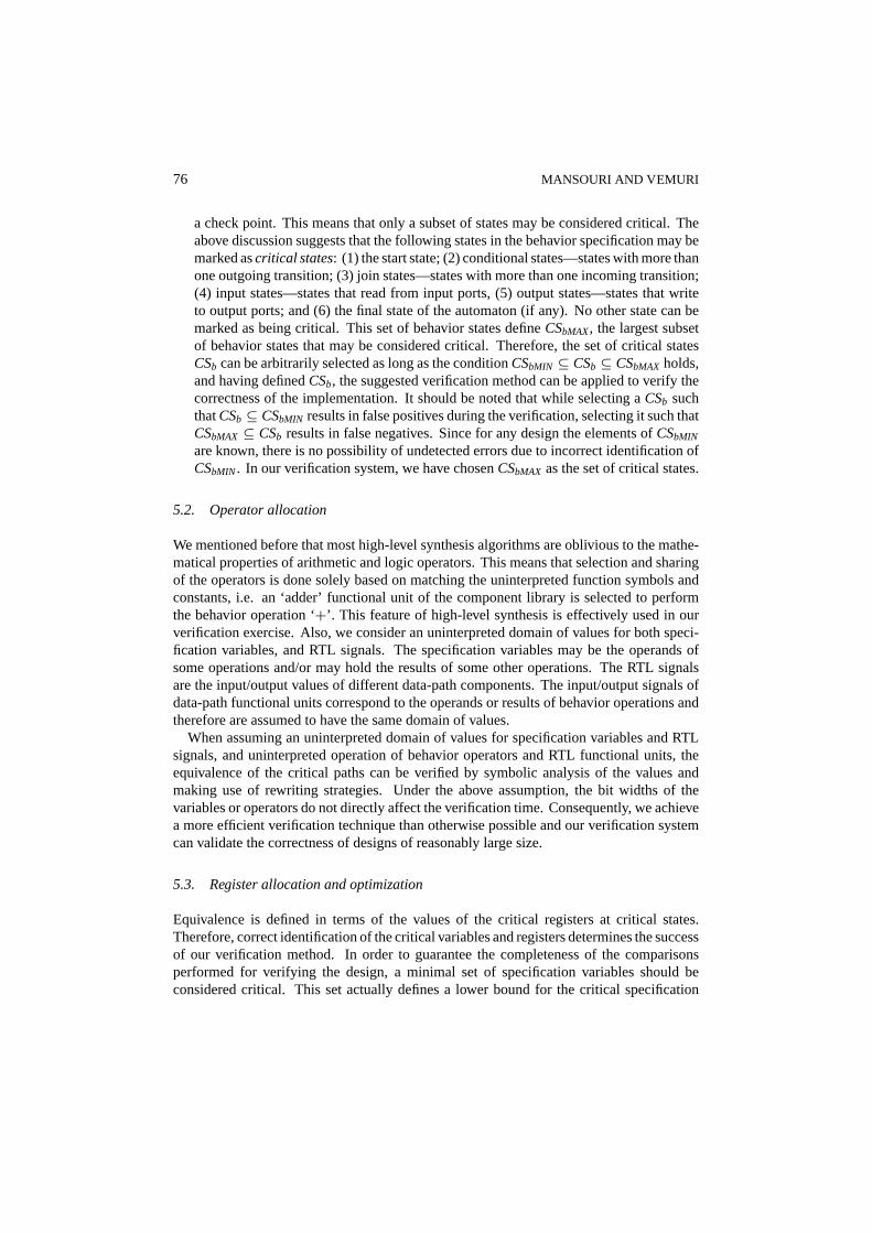
a check point. This means that only a subset of states may be considered critical. Theabove discussion suggests that the following states in the behavior specification may bemarked ascritical states: (1) the start state; (2) conditional states—states with more thanone outgoing transition; (3) join states—states with more than one incoming transition;(4) input states—states that read from input ports, (5) output states—states that writeto output ports; and (6) the final state of the automaton (if any). No other state can bemarked as being critical. This set of behavior states defineCSbMAX, the largest subsetof behavior states that may be considered critical. Therefore, the set of critical statesCSb can be arbitrarily selected as long as the conditionCSbMIN ⊆ CSb ⊆ CSbMAX holds,and having definedCSb, the suggested verification method can be applied to verify thecorrectness of the implementation. It should be noted that while selecting aCSb suchthatCSb ⊆ CSbMIN results in false positives during the verification, selecting it such thatCSbMAX ⊆ CSb results in false negatives. Since for any design the elements ofCSbMIN
are known, there is no possibility of undetected errors due to incorrect identification ofCSbMIN. In our verification system, we have chosenCSbMAX as the set of critical states.
5.2. Operator allocation
We mentioned before that most high-level synthesis algorithms are oblivious to the mathe-matical properties of arithmetic and logic operators. This means that selection and sharingof the operators is done solely based on matching the uninterpreted function symbols andconstants, i.e. an ‘adder’ functional unit of the component library is selected to performthe behavior operation ‘+’. This feature of high-level synthesis is effectively used in ourverification exercise. Also, we consider an uninterpreted domain of values for both speci-fication variables, and RTL signals. The specification variables may be the operands ofsome operations and/or may hold the results of some other operations. The RTL signalsare the input/output values of different data-path components. The input/output signals ofdata-path functional units correspond to the operands or results of behavior operations andtherefore are assumed to have the same domain of values.
When assuming an uninterpreted domain of values for specification variables and RTLsignals, and uninterpreted operation of behavior operators and RTL functional units, theequivalence of the critical paths can be verified by symbolic analysis of the values andmaking use of rewriting strategies. Under the above assumption, the bit widths of thevariables or operators do not directly affect the verification time. Consequently, we achievea more efficient verification technique than otherwise possible and our verification systemcan validate the correctness of designs of reasonably large size.
5.3. Register allocation and optimization
Equivalence is defined in terms of the values of the critical registers at critical states.Therefore, correct identification of the critical variables and registers determines the successof our verification method. In order to guarantee the completeness of the comparisonsperformed for verifying the design, a minimal set of specification variables should beconsidered critical. This set actually defines a lower bound for the critical specification
AUTOMATED CORRECTNESS CONDITION GENERATION 77
variables. The following set of specification variables defineCRbMIN, the minimal set ofcritical specification variables: (1) input variables—the variables that directly read frominput ports, and (2) output variables—the variables that directly write to output ports.Therefore, the set of critical specification variablesCRb, should always be selected suchtahtCRbMIN ⊆ CRb.
In a simplistic synthesis process, with no register optimization, all critical variables arepreserved by the HLS tool and manifest in the RTL design in the form of critical registers. Inthis case, there is a one-to-one mapping between the specification variables and a subset ofdesign registers. As the lower limit,CRbMIN may be considered the set of critical variables.As the upper limit, all the specification variables may be marked as critical. In this case,comparing all the critical variables and their corresponding RTL registers is sufficient tovalidate the correctness of the implementation, even though it may not be necessary. Astatic register binding functionBrs : CRb 7→ CRd can define the exact relation betweenthe critical specification variables and critical design registers. This is not the case whenregister optimization is performed on the design.
Considering all the specification variables and their corresponding design registers criti-cal, is an incorrect assumption which may lead to incorrect verification results. During theverification process, the equivalence ofpb and pd, a pair of behavior-design critical paths,is determined by comparing the value of each critical specification variable with the contentof its corresponding design register, at the terminating states of these paths. However, if aspecification variablerb, is not live at any state along a critical pathpb, the equivalence ofpb andpd = Bp(pb) may be determined independent from the value ofrb at the final stateof pb. Sincerb has no live value along the critical pathpb, comparing its value at the finalstate ofpb with the contents of any design register at the final state ofpd may result in theincorrect implication thatpb and pd are not equivalent (false negative).
The goal of register optimization is to share registers whose life-times do not overlapacross the scheduled time-scales. This is done by life cycle analysis of the design registers.Two types of register allocation-optimization schemes are commonly found in high-levelsynthesis tools:value basedand carrier based. When transformations based on theseschemes are performed during the synthesis process, the binding relation between thespecification variables and RTL registers is no longer bijective. A static register bindingfunction is not suitable for defining this relation. Appropriate register binding functionsshould be defined for each scheme. Accordingly, the verification strategies should beadjusted to account for these new binding relations.
The carrier based register allocation scheme yields a mapping from the variables tothe registers. FACET [50], HAL [38], and CHARM [56] use carrier-based techniques forregister optimization. Register optimization is only possible when two (or more) variableshave non overlapping lifetimes, in which case they are bound to the same register. Therefore,the mapping from the specification variables to RTL registers is a many to one relation. Theregister allocation algorithm guarantees that only variables with non-overlapping life-timesare mapped to the same register. Therefore, at any state at most one variable (the one thatis live) may be mapped to the corresponding register.
In value-based approach, register optimization is modeled as the problem of mappingdata values produced and used by operations in a data flow graph representation of the

78 MANSOURI AND VEMURI
Figure 4. Example specification fragment.
specification into registers. Considering the specification fragment of figure 4, a valuebased register allocation scheme may assign registerR1, R2, R3 andR4 to the valuesB+1,A+ 1, B+ 2 andA+ 2 respectively. So, if we assume that all the variables of this partialspecification are critical, then along the critical path [. . . , S3, S4, . . .], the specificationvariable A is mapped to the registerR1 and along the critical path [. . . , S7, S8, . . .] it ismapped toR3. Many high-level synthesis systems such as REAL [28], EMUCS [47] andEASY [45] use value-based register optimization approach. In this approach, the registeroptimization problem can be modeled as a channel routing problem; the life span of eachvalue is modeled as a net interval. The minimum number of tracks corresponds to thenumber of registers needed.
It is obvious that a variable during its lifetime, or even at different states of the same criticalpath, may assume different values. Also, it is possible that the same value is assigned todifferent variables. Hence, in this scheme, the mapping from specification variables to RTLregisters is a ‘many to many’ relation. Unlike the carrier-based register allocation scheme,the critical variables do not uniquely correspond to the RTL registers along each criticalpath. But, each variable at the final state of a critical path, holds the last value assigned to it,and it is this value which will be compared to the value of a corresponding register duringthe verification process. Therefore, along each critical path, a variable can be uniquelymapped to the register corresponding to the last value assigned to it.
In both schemes, a variable can be critical only at those states when it is alive. This meansthat a variable may be critical along certain critical paths and not critical along the others.Therefore, the binding function depends on the critical paths as well as the variables, i.e.Br : CRb×CPb 7→ CRd. This binding function is referred to as adynamic register bindingfunction. It uniquely maps each critical variable to an RTL register along each criticalpath.
Criticality masking technique. The verification method we introduced in Section 4 isapplicable, even when register optimization is performed as part of synthesis process. Thearguments presented in that section about the equivalence of the specification and imple-mentation are still valid and can be used for the synthesized designs that have undergoneregister optimization, with the following two modifications:

AUTOMATED CORRECTNESS CONDITION GENERATION 79
— The static register binding functionBr : CRb 7→ CRd should be replaced by the dynamicregister binding functionBr : CRb × CPb 7→ CRd throughout the whole discussion.
— We introduce the functionTailb(eb) to denote thetail of behavior execution pathseb. Thetail of an execution path is the final critical path on the execution path that is defined byits final two critical states. Now, the equivalent states of the two designs can be redefinedto account for register optimization.
We say that a behavior critical statesb and the RTL critical stateBs(sb) areequivalent,provided:
S0b ≡ S0d ⇒∀e∈ EPb, sb = Tb(e), ∀rb ∈ CRb :
(live(rb,Tailb(e))⇒Vb(e, rb) = Vd(Be(e), Br (rb,Tailb(e))))
We denote state equivalence bysb ≡ Bs(sb). This means that a critical behavior stateand a design state are equivalent iff at behavior state the value of each critical variablethat is live across the critical path ending at that state, is equivalent to the value of itscorresponding design register at the design state.
This technique of equivalence checking is calledcriticality masking technique, sinceduring verification, for each critical path, the criticality of the variables that do not have alive value along that path is masked and only those critical variables which have a live valuealong that path determine the equivalence of the path with its corresponding design criticalpath.
5.4. Interconnect allocation
Two possible interconnect allocation schemes exist in synthesis: point-to-point interconnectallocation and bus allocation. Data-path interconnections represent data-flow in behaviorspecification. Interconnect allocation (optimization) is a procedure similar to register al-location (optimization). To allow sharing of the interconnections during the interconnectallocation phase multiplexers may be introduced to the circuit. During the verification pro-cess, the contents of different registers in terms of uninterpreted values are symbolicallyevaluated. During this analysis, data-path components are traversed and all components,including the multiplexers and buses are accounted for. Therefore, introduction of the mul-tiplexers to design does not require any adjustments to the verification algorithm.
In our verification technique all values, constants and operators are uninterpreted, andall signals have the same type. The input and output values of all the combinationaland sequential components of the data-path are of this type, too. The comparison ofuninterpreted functions and values in our approach has the noticeable advantage of reducingthe complexities associated with bit-vector signal types. However, in the synthesis of RTLdesigns, there are situations when bit level effects should be dealt with.

80 MANSOURI AND VEMURI
In high-level synthesis, the proportion of the signals that need to be split to smaller bit-vectors or need to be merged together to generate larger bit-vectors is often small comparedto the total number of signals in the circuit. Dealing with all signals at the bit-level tocover these special cases imposes too much complexity on the verification process to beacceptable. We introduce two virtual components ‘SPLIT’ and ‘MERGE’ to the set ofsynthesis resources to be able to model all possible types of interconnections in the data-path of the RTL design. This allows us to present a solution to the problems at the bit levelwhenever necessary, while maintaining the assumption of uninterpreted signal types at allother times.
5.5. Controller generation
At this point of the synthesis process, the number of controller states, its inputs at each state(the flags from the data-path) and its outputs at each state (the control signals) are known.With this information the controller of the RTL design is generated. The incorrect design ofthe controller results in generation of incorrect control signals. The incorrect control signalsresult in incorrect RTL data-transfers and are detected during the verification process. Thecontroller generation stage has no direct effect in verification strategies.
6. Enhancements
In the preceding sections, for clarity of presentation, we made several assumptions about thesynthesis tool. Some of these assumptions are easily alleviated. In particular, the correctnesscondition generator we implemented incorporates the following enhancements to the basictechnique discussed in the previous sections:
1. Freedom of the Scheduler: We assumed earlier that the CDFG scheduler does not movebehavioral assignments and operators across critical nodes. However, some schedulers,including the DSS scheduler, do move operators and assignments across input/outputstatements as long as no data dependency is violated. This is handled by masking thecriticality of certain variables (registers) at certain critical states. Essentially, a criticalvariable whose instance is moved by the scheduler across a critical state is masked at thatstate and the register to which that variable is bound is also masked at the correspondingRTL state. For these masked variables (registers), comparison is turned-off at that state.This masking is taken into account by the CCG when correctness lemmas are generated.(Although not necessary for the DSS scheduler, this technique may be further extendedin the context of schedulers that may move operations across conditional/join nodeboundaries.)
2. Commuting ALU Inputs During Interconnect Allocation: Contrary to the assumptionmade earlier, the DSS interconnect allocation algorithms do allow exploitation of com-mutativity of certain operators (addition, multiplication, etc.) in order to reduce in-terconnect cost by eliminating multiplexers. This is handled by keeping track of theplaces where commutativity is exploited, generating commutativity axioms for those(uninterpreted) functions, and instantiating these axioms during the proof.
AUTOMATED CORRECTNESS CONDITION GENERATION 81
3. Folding Operators into Registers: As in the case of many synthesis tools, DSS permitsfolding certain types of operators such as addition/subtraction-by-1 and divide/multiply-by-2 into register operations such as increment/decrement, and shift right/left. This ishandled in a straight-forward way by generating appropriate register axioms.
7. Correctness Condition Generator
In this section, we discuss how the proof of correctness of the designs is generated by thecorrectness condition generator, CCG. We assume that the operating environment of thedesigns ensures thatS0b ≡ S0d. Typically, the environment ensures that all the data andcontrol registers are reset at the start states. The goal of our proof effort is to show that eachcritical path in the behavior is equivalent to its corresponding critical path in the structure.We determine this by using symbolic term rewriting in a higher-order logic theorem prover.
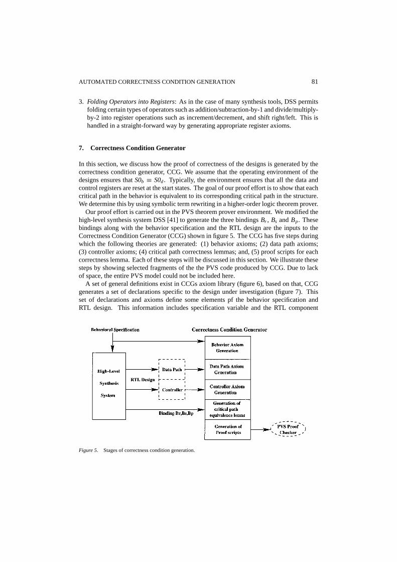
Our proof effort is carried out in the PVS theorem prover environment. We modified thehigh-level synthesis system DSS [41] to generate the three bindingsBr , Bs andBp. Thesebindings along with the behavior specification and the RTL design are the inputs to theCorrectness Condition Generator (CCG) shown in figure 5. The CCG has five steps duringwhich the following theories are generated: (1) behavior axioms; (2) data path axioms;(3) controller axioms; (4) critical path correctness lemmas; and, (5) proof scripts for eachcorrectness lemma. Each of these steps will be discussed in this section. We illustrate thesesteps by showing selected fragments of the the PVS code produced by CCG. Due to lackof space, the entire PVS model could not be included here.
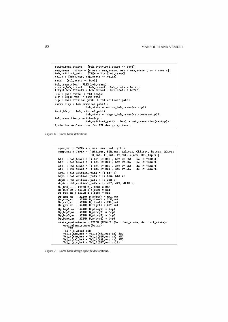
A set of general definitions exist in CCGs axiom library (figure 6), based on that, CCGgenerates a set of declarations specific to the design under investigation (figure 7). Thisset of declarations and axioms define some elements pf the behavior specification andRTL design. This information includes specification variable and the RTL component
Figure 5. Stages of correctness condition generation.
82 MANSOURI AND VEMURI
Figure 6. Some basic definitions.
Figure 7. Some basic design-specific declarations.
AUTOMATED CORRECTNESS CONDITION GENERATION 83
declaration, critical path specification for both behavior and RTL automata, and bindingfunctionsBr , Bs andBp.
7.1. Behavior axiom generation
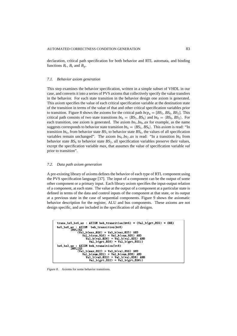
This step examines the behavior specification, written in a simple subset of VHDL in ourcase, and converts it into a series of PVS axioms that collectively specify the value transfersin the behavior. For each state transition in the behavior design one axiom is generated.This axiom specifies the value of each critical specification variable at the destination stateof the transition in terms of the value of that and other critical specification variables priorto transition. Figure 8 shows the axioms for the critical pathbcp4 = [BS5,BS6,BS2]. Thiscritical path consists of two state transitionsbt6 = 〈BS5,BS6〉 andbt8 = 〈BS6,BS2〉. Foreach transition, one axiom is generated. The axiombs5 bs6 ax for example, as the namesuggests corresponds to behavior state transitionbt6 = 〈BS5,BS6〉. This axiom is read: “Intransitionbt6, from behavior stateBS5 to behavior stateBS6, the values of all specificationvariables remain unchanged”. The axiombs6 bs2 ax is read: “In a transitionbt8 frombehavior stateBS6 to behavior stateBS2, all specification variables preserve their values,except the specification variablemax, that assumes the value of specification variablevalprior to transition”.
7.2. Data path axiom generation
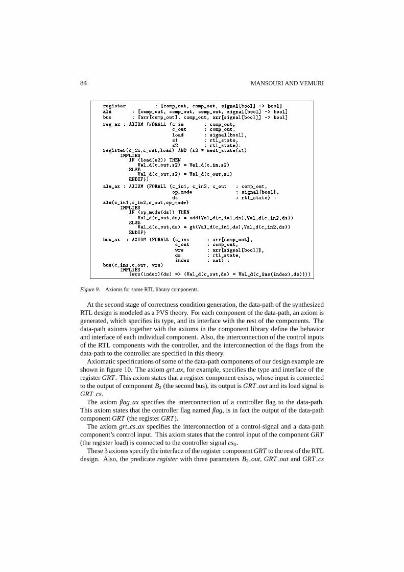
A pre-existing library of axioms defines the behavior of each type of RTL component usingthe PVS specification language [37]. The input of a component can be the output of someother component or a primary input. Each library axiom specifies the input-output relationof a component, at each state. The value at the output of a component at a particular state isdefined in terms of the data and control inputs of the component at that state, or its outputat a previous state in the case of sequential components. Figure 9 shows the axiomaticbehavior description for the register, ALU and bus components. These axioms are notdesign specific, and are included in the specification of all designs.
Figure 8. Axioms for some behavior transitions.
84 MANSOURI AND VEMURI
Figure 9. Axioms for some RTL library components.
At the second stage of correctness condition generation, the data-path of the synthesizedRTL design is modeled as a PVS theory. For each component of the data-path, an axiom isgenerated, which specifies its type, and its interface with the rest of the components. Thedata-path axioms together with the axioms in the component library define the behaviorand interface of each individual component. Also, the interconnection of the control inputsof the RTL components with the controller, and the interconnection of the flags from thedata-path to the controller are specified in this theory.
Axiomatic specifications of some of the data-path components of our design example areshown in figure 10. The axiomgrt ax, for example, specifies the type and interface of theregisterGRT. This axiom states that a register component exists, whose input is connectedto the output of componentB2 (the second bus), its output isGRT outand its load signal isGRT cs.
The axiomflag ax specifies the interconnection of a controller flag to the data-path.This axiom states that the controller flag namedflag, is in fact the output of the data-pathcomponentGRT (the registerGRT).
The axiomgrt cs ax specifies the interconnection of a control-signal and a data-pathcomponent’s control input. This axiom states that the control input of the componentGRT(the register load) is connected to the controller signalcs0.
These 3 axioms specify the interface of the register componentGRTto the rest of the RTLdesign. Also, the predicateregisterwith three parametersB2 out, GRT out andGRT cs

AUTOMATED CORRECTNESS CONDITION GENERATION 85
Figure 10. Axioms for some data path components.
together with thereg ax axiom of the RTL component library, specify the behavior ofthe componentGRT as a relation between its inputs (data inputB2 out and control inputGRT cs) and its outputGRT out.
7.3. Controller axiom generation
At this step of correctness condition generation, a PVS model of the RTL controller isgenerated. The functionsControl Signalandnext stateare extracted from the controllerand converted to PVS functions. In functionControl Signal, the values of control signalsfrom the controller to data-path at each state of the controller are defined. In functionnext state, the next state of each state is determined in terms of the current state and thevalues of the flags from the data-path to the controller at that state. The functionnext stateand parts of the functionControl Signal, for our example are shown in figure 11.
Figure 11. RTL controller.
86 MANSOURI AND VEMURI
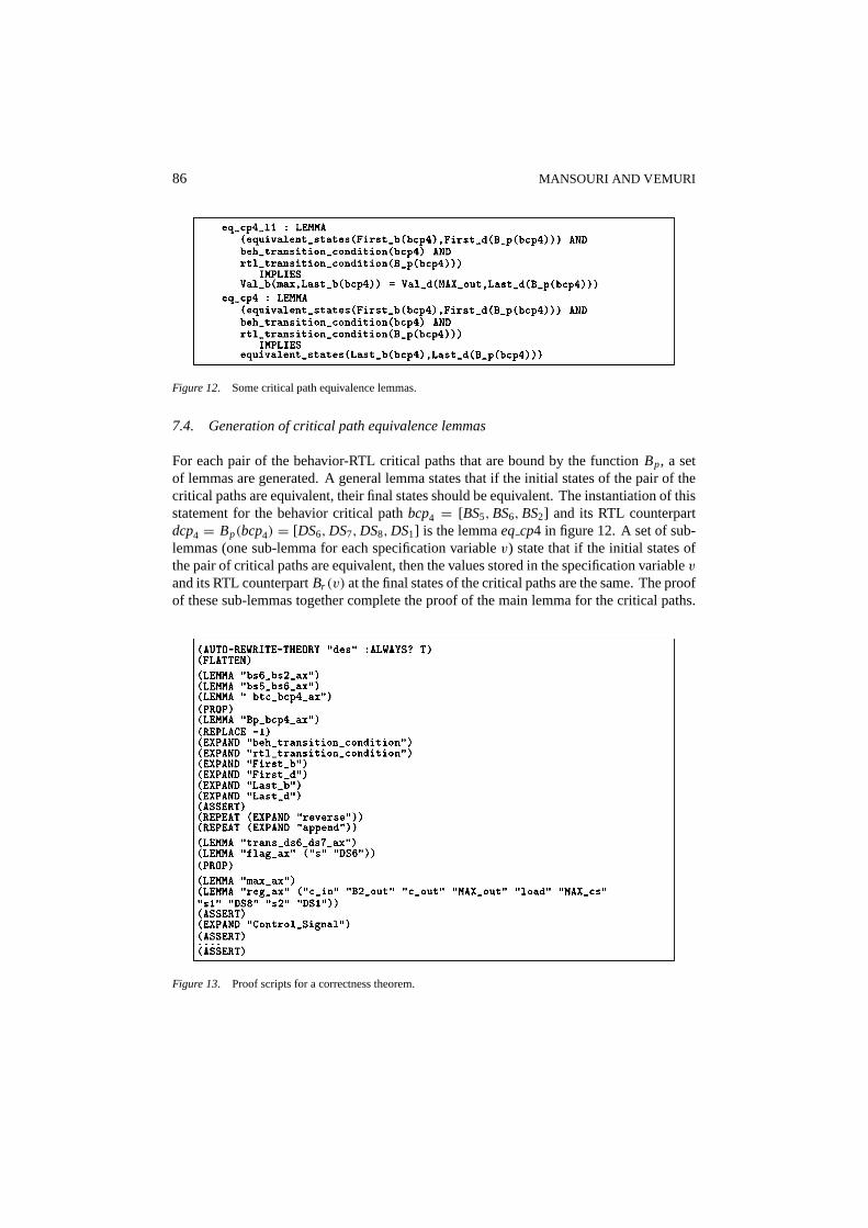
Figure 12. Some critical path equivalence lemmas.
7.4. Generation of critical path equivalence lemmas
For each pair of the behavior-RTL critical paths that are bound by the functionBp, a setof lemmas are generated. A general lemma states that if the initial states of the pair of thecritical paths are equivalent, their final states should be equivalent. The instantiation of thisstatement for the behavior critical pathbcp4 = [BS5,BS6,BS2] and its RTL counterpartdcp4 = Bp(bcp4) = [DS6,DS7,DS8,DS1] is the lemmaeq cp4 in figure 12. A set of sub-lemmas (one sub-lemma for each specification variablev) state that if the initial states ofthe pair of critical paths are equivalent, then the values stored in the specification variablev
and its RTL counterpartBr (v) at the final states of the critical paths are the same. The proofof these sub-lemmas together complete the proof of the main lemma for the critical paths.
Figure 13. Proof scripts for a correctness theorem.
AUTOMATED CORRECTNESS CONDITION GENERATION 87
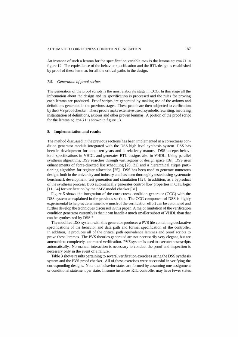
An instance of such a lemma for the specification variablemaxis the lemmaeq cp4 l1 infigure 12. The equivalence of the behavior specification and the RTL design is establishedby proof of these lemmas for all the critical paths in the design.
7.5. Generation of proof scripts
The generation of the proof scripts is the most elaborate stage in CCG. In this stage all theinformation about the design and its specification is processed and the rules for provingeach lemma are produced. Proof scripts are generated by making use of the axioms anddefinitions generated in the previous stages. These proofs are then subjected to verificationby the PVS proof checker. These proofs make extensive use of symbolic rewriting, involvinginstantiation of definitions, axioms and other proven lemmas. A portion of the proof scriptfor the lemmaeq cp4 l1 is shown in figure 13.
8. Implementation and results
The method discussed in the previous sections has been implemented in a correctness con-dition generator module integrated with the DSS high level synthesis system. DSS hasbeen in development for about ten years and is relatively mature. DSS accepts behav-ioral specifications in VHDL and generates RTL designs also in VHDL. Using parallelsynthesis algorithms, DSS searches through vast regions of design space [16]. DSS usesenhancements of force-directed list scheduling [20, 21] and a hierarchical clique parti-tioning algorithm for register allocation [25]. DSS has been used to generate numerousdesigns both in the university and industry and has been thoroughly tested using systematicbenchmark development, test generation and simulation [52]. In addition, as a byproductof the synthesis process, DSS automatically generates control flow properties in CTL logic[11, 34] for verification by the SMV model checker [31].
Figure 5 shows the integration of the correctness condition generator (CCG) with theDSS system as explained in the previous section. The CCG component of DSS is highlyexperimental to help us determine how much of the verification effort can be automated andfurther develop the techniques discussed in this paper. A major limitation of the verificationcondition generator currently is that it can handle a much smaller subset of VHDL than thatcan be synthesized by DSS.4
The modified DSS system with this generator produces a PVS file containing declarativespecifications of the behavior and data path and formal specification of the controller.In addition, it produces all of the critical path equivalence lemmas and proof scripts toprove these lemmas. The PVS theories generated are not necessarily very elegant, but areamenable to completely automated verification. PVS system is used to execute these scriptsautomatically. No manual interaction is necessary to conduct the proof and inspection isnecessary only in the event of a failure.
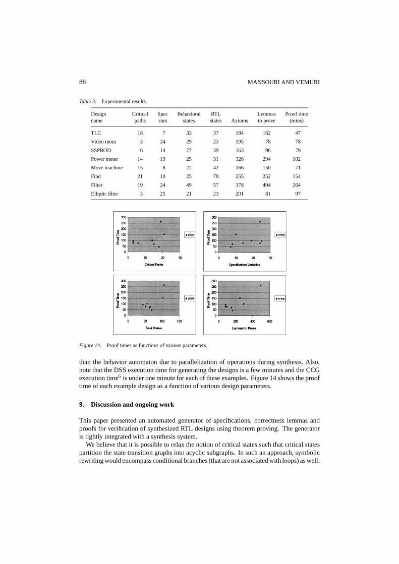
Table 3 shows results pertaining to several verification exercises using the DSS synthesissystem and the PVS proof checker. All of these exercises were successful in verifying thecorresponding designs. Note that behavior states are formed by assuming one assignmentor conditional statement per state. In some instances RTL controller may have fewer states
88 MANSOURI AND VEMURI
Table 3. Experimental results.
Design Critical Spec Behavioral RTL Lemmas Proof timename paths vars states states Axioms to prove (mins)
TLC 18 7 33 37 184 162 47
Video mom 3 24 29 23 195 78 78
SSPROD 6 14 27 39 163 96 79
Power meter 14 19 25 31 328 294 102
Move machine 15 8 22 42 166 150 71
Find 21 10 25 78 255 252 154
Filter 19 24 49 57 378 494 264
Elliptic filter 3 25 21 23 201 81 97
Figure 14. Proof times as functions of various parameters.
than the behavior automaton due to parallelization of operations during synthesis. Also,note that the DSS execution time for generating the designs is a few minutes and the CCGexecution time6 is under one minute for each of these examples. Figure 14 shows the prooftime of each example design as a function of various design parameters.
9. Discussion and ongoing work
This paper presented an automated generator of specifications, correctness lemmas andproofs for verification of synthesized RTL designs using theorem proving. The generatoris tightly integrated with a synthesis system.
We believe that it is possible to relax the notion of critical states such that critical statespartition the state transition graphs into acyclic subgraphs. In such an approach, symbolicrewriting would encompass conditional branches (that are not associated with loops) as well.
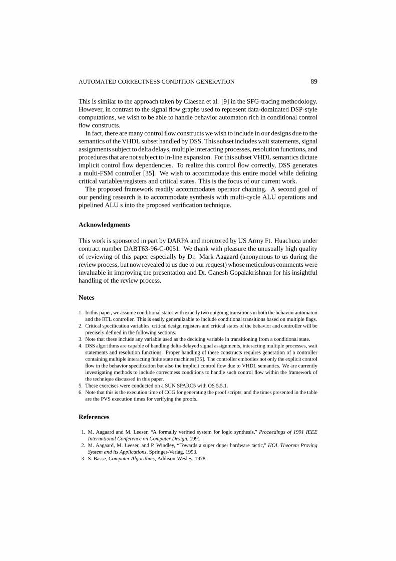
AUTOMATED CORRECTNESS CONDITION GENERATION 89
This is similar to the approach taken by Claesen et al. [9] in the SFG-tracing methodology.However, in contrast to the signal flow graphs used to represent data-dominated DSP-stylecomputations, we wish to be able to handle behavior automaton rich in conditional controlflow constructs.
In fact, there are many control flow constructs we wish to include in our designs due to thesemantics of the VHDL subset handled by DSS. This subset includes wait statements, signalassignments subject to delta delays, multiple interacting processes, resolution functions, andprocedures that are not subject to in-line expansion. For this subset VHDL semantics dictateimplicit control flow dependencies. To realize this control flow correctly, DSS generatesa multi-FSM controller [35]. We wish to accommodate this entire model while definingcritical variables/registers and critical states. This is the focus of our current work.
The proposed framework readily accommodates operator chaining. A second goal ofour pending research is to accommodate synthesis with multi-cycle ALU operations andpipelined ALU s into the proposed verification technique.
Acknowledgments
This work is sponsored in part by DARPA and monitored by US Army Ft. Huachuca undercontract number DABT63-96-C-0051. We thank with pleasure the unusually high qualityof reviewing of this paper especially by Dr. Mark Aagaard (anonymous to us during thereview process, but now revealed to us due to our request) whose meticulous comments wereinvaluable in improving the presentation and Dr. Ganesh Gopalakrishnan for his insightfulhandling of the review process.
Notes
1. In this paper, we assume conditional states with exactly two outgoing transitions in both the behavior automatonand the RTL controller. This is easily generalizable to include conditional transitions based on multiple flags.
2. Critical specification variables, critical design registers and critical states of the behavior and controller will beprecisely defined in the following sections.
3. Note that these include any variable used as the deciding variable in transitioning from a conditional state.4. DSS algorithms are capable of handling delta-delayed signal assignments, interacting multiple processes, wait
statements and resolution functions. Proper handling of these constructs requires generation of a controllercontaining multiple interacting finite state machines [35]. The controller embodies not only the explicit controlflow in the behavior specification but also the implicit control flow due to VHDL semantics. We are currentlyinvestigating methods to include correctness conditions to handle such control flow within the framework ofthe technique discussed in this paper.
5. These exercises were conducted on a SUN SPARC5 with OS 5.5.1.6. Note that this is the execution time of CCG for generating the proof scripts, and the times presented in the table
are the PVS execution times for verifying the proofs.
References
1. M. Aagaard and M. Leeser, “A formally verified system for logic synthesis,”Proceedings of 1991 IEEEInternational Conference on Computer Design, 1991.
2. M. Aagaard, M. Leeser, and P. Windley, “Towards a super duper hardware tactic,”HOL Theorem ProvingSystem and its Applications, Springer-Verlag, 1993.
3. S. Basse,Computer Algorithms, Addison-Wesley, 1978.
90 MANSOURI AND VEMURI
4. R.A. Bergamaschi and S. Rajel, “Observable time windows: verifying the results of high-level synthesis,”IEEE Design & Test of Computers, 1997.
5. R.E. Bryant, “Symbolic boolean manipulation with ordered binary decision diagrams,” Technical ReportCMU-CS-92-160, School of Computer Science, Carnegie Mellon University, 1992.
6. R.E. Bryant, “Binary decision diagrams and beyond: enabling technologies for formal verification,”EmbeddedTutorial at International Conference on Computer-Aided Design, 1995.
7. J.R. Burch and D.L. Dill, “Automatic verification of pipelined microprocessor control,”Proceedings ofComputer-Aided Verification, 1994.
8. R. Camposano and W. Wolf,High-Level VLSI Synthesis, Kluwer Academic Publishers, 1991.9. L. Claesen, M. Genoe, E. Verlind, F. Proesmans, and H.D. Man, “SFG-tracing: a methodology of design for
verifiability,” Proceedings of Advanced Workshop on Correct Hardware Design Methodologies, 1991.10. L. Claesen, F. Proesmans, E. Verlind, and H.D. Man, “SFG-tracing: a methodology for the automatic veri-
fication of MOS transistor level implementations from high-level behavioral specifications,”Proceedings ofInternational Workshop on Formal Methods in VLSI Design, 1991.
11. E. Clarke, E. Emerson, and A. Sistla, “Automatic verification of finite-state concurrent systems using temporallogic specifications,”ACM Transactions on Prog. Lang. Syst., 1986.
12. F. Corella, “Automated verification of behavioral equivalence for microprocessors,” Research Report, IBMResearch division, T.J. Watson Research Center, 1992.
13. F. Corella, “Automated high-level verification against clocked algorithmic specifications,”Proceedings ofComputer Hardware Description Languages and Their Applications, 1993.
14. F. Corella, R. Camposano, R. Bergamaschi, and M. Payer, “Verification of synchronous sequential circuitsobtained from algorithmic specifications,”Proceedings of International Workshop on Formal Methods in VLSIDesign, 1991.
15. G. De-Micheli,Synthesis and Optimization of Digital Circuits, McGraw-Hill, 1994.16. R. Dutta, J. Roy, and R. Vemuri, “Distributed design space exploration for high-level synthesis systems,”29th
Design Automation Conference, 1992.17. D. Eisnbiegler and R. Kumar, “Formally embedding existing high level synthesis algorithms,”Correct Hard-
ware Design and Verification Methods, Springer, 1995.18. F. Feldbusch and R. Kumar, “Verification of synthesized circuits at register transfer level with flow graphs,”
Proceedings of IEEE European Design Automation Conference, 1991.19. D. Gajski, N. Dutt, A. Wu, and S. Lin,High-Level Synthesis, Introduction to Chip and System Design, Kluwer
Academic Publishers, 1992.20. S. Govindarajan and R. Vemuri, “Cone-based clustering heuristic for list scheduling algorithms,”Proceedings
of the European Design and Test Conference, 1997.21. S. Govindarajan and R. Vemuri, “Dynamic bounding of successor force computations in the force directed
list scheduling algorithm,”Proceedings of International Conference on Computer Design, 1997.22. D. Greve, “Symbolic simulation of the JEM1 microprocessor,”Proceedings of the 2nd International Confer-
ence on Formal Methods in Computer-Aided Design, 1998.23. W. Hunt,FM8501: A Verified Microprocessor, Springer-Verlag, 1994.24. S. Johnson,Synthesis of Digital Designs from Recursion Equations, MIT Press, 1984.25. S. Katkoori, J. Roy, and R. Vemuri, “A hierarchical register optimization algorithm for behavioral synthesis,”
Proceedings of International Conference on VLSI Design, 1996.26. D.W. Knapp,Behavioral Synthesis: Digital System Design Using the Synopsys Behavioral Compiler, Prentice
Hall, 1996.27. T. Kropf, K. Schneider, and R. Kumar, “A formal framework for high level synthesis,”Theorem Provers in
Circuit Design, Springer-Verlag, 1994.28. F. Kurdahi and A. Parker, “REAL: A program for REgister ALlocation,”24th Design Automation Conference,
1987.29. N. Mansouri and R. Vemuri, “A methodology for completely automated verification of synthesized RTL
designs and its integration with a high-level synthesis tool,”Proceedings of International Conference onFormal Methods in Computer-Aided Design, 1998.
30. M. McFarland, “An abstract model of behavior for hardware descriptions,”IEEE Transactions on Computers,1983.
AUTOMATED CORRECTNESS CONDITION GENERATION 91
31. K.L. McMillan, Symbolic Model Checking: An Approach to the State Explosion Problem, Carnegie MellonUniversity, 1992.
32. J.S. Moore, “Symbolic simulation: an ACL2 approach,”Proceedings of the 2nd International Conference onFormal Methods in Computer-Aided Design, 1998.
33. N. Narasimhan, E. Teica, R. Radhakrishnan, S. Govindarajan, and R. Vemuri, “Theorem proving guideddevelopment of formal assertions in a resource-constrained scheduler for high-level synthesis,”Proceedingsof International Conference on Computer Design (ICCD’98), 1998, pp. 392–399.
34. N. Narasimhan and R. Vemuri, “Specification of control flow properties for verification of synthesized VHDLdesigns,”Proceedings of International Conference in Formal Methods in Computer Aided Design, 1996.
35. N. Narasimhan and R. Vemuri, “Synchronous controller models for synthesis from communicating VHDLprocesses,”Ninth International Conference on VLSI Design, 1996.
36. N. Narasimhan and R. Vemuri, “On the effectiveness of theorem proving guided discovery of formal assertionsfor a register allocator in a high-level synthesis system,”Proceedings of 11th Conference on Theorem Provingin Higher Order Logics (TPHOL’98), 1998.
37. S. Owre, N. Shankar, and J.M. Rushby, “The PVS specification language (beta release),”29th DesignAutomation Conference, 1992.
38. P. Pualin, J. Knight, and E. Girczyck, “HAL: a multi-paradigm approach to automatic data path synthesis,”24th ACM/IEEE Desgin Automation Conference, 1986.
39. S. Rajan, “Correctness transformations in high level synthesis: formal verification,”Proceedings of theInternational Conference on Computer Hardware Description Languages, 1995.
40. S. Rajan, J. Joyce, and C. Seger, “From abstract data types to shift registers: a case study in formal specifi-cation and verification at differing levels of abstraction using theorem proving and symbolic simulation,”6thInternational Workshop on Higher Order Logic Theorem Proving and Its Applications, 1993.
41. J. Roy, N. Kumar, R. Dutta, and R. Vemuri, “DSS: a distributed high-level synthesis system,”IEEE Designand Test of Computers, 1992.
42. S. Devadas, T. Ma, and R. Newton, “On verification of sequential machines at differing levels of abstraction,”IEEE Transactions on Computer-Aided Design, 1988.
43. N. Shankar, S. Owre, and J.M. Rushby,The PVS Proof Checker: A Reference Manual (Beta Release),1993.
44. M.K. Srivas and S.P. Miller, “Formal verification of the AAMP5 microprocessor,”Applications of FormalMethods, Prentice Hall International, 1995.
45. L. Stok and R.V.D. Born, “Easy: multiprocessor architecture optimiztion,”Proceedings of InternationalWorkshop on Logic and Architecture Synthesis for Silicon Compilers, 1998.
46. A. Takach and W. Wolf,Scheduling Constraint Generation for Communicating Processes, Princeton Univer-sity, 1993.
47. D. Thomas, C.Y.H. III, T. Kowalski, J. Rajan, and A. Walker, “Automatic data path synthesis,”IEEE Trans-actions on Computers, 1983.
48. D. Thomas, E. Lagnese, R. Walker, J. Nestor, J. Rajan, and R. Blackburn,Algorithmic and Register TransferLevel Synthesis: The System Architect’s Workbench, Kluwer Academic Publishers, 1990.
49. D.E. Thomas, R.L. Blackburn, and J.V. Rajan, “Linking the behavioral and structural domains of representationfor digital system design,”IEEE Transactions on Computer Aided Design, 1987.
50. C. Tseng and D.P. Siewiorek, “Facet: a procedure for the automated synthesis of digital systems,”20thACM/IEEE Design Automation Conference, 1983.
51. R. Vemuri, “On the notion of normal form register-level structures and its applications in design-spaceexploration,”Proceedings of IEEE European Design Automation Conference, 1990.
52. R. Vemuri, P. Mamtora, P. Sinha, N. Kumar, and J.R.R. Vutukuru, “Experiences in functional validation of ahigh level synthesis system,”Proceedings of 30th ACM/IEEE Design Automation Conference, 1993.
53. R. Walker and R. Camposano,A Survey of High-Level Synthesis Systems, Kluwer Academic Publishers, 1990.54. P. Windley,The Practical Verification of Microprocessor Designs, Compcon, 1991.55. P.J. Windley, “Verifying pipelined microprocessors,”Proceedings of the International Conference on Com-
puter Hardware Description Languages, 1995.56. N. Woo, “A global, dymanic register allocation and binding for data path synthesis system,”27th Design
Automation Conference, 1990.
Related Documents