UNCLASSIFIED AD NUMBER ADB001855 CLASSIFICATION CHANGES TO: unclassified FROM: confidential LIMITATION CHANGES TO: Approved for public release, distribution unlimited FROM: Distribution authorized to U.S. Gov't. agencies only; Test and Evaluation; 06 JUN 1959. Other requests shall be referred to Defense Nuclear Agency, Alexandria, VA 22310. AUTHORITY DNA ltr, 14 Sep 1995; DNA ltr, 14 Sep 1995 THIS PAGE IS UNCLASSIFIED

Welcome message from author
This document is posted to help you gain knowledge. Please leave a comment to let me know what you think about it! Share it to your friends and learn new things together.
Transcript
UNCLASSIFIED
AD NUMBERADB001855
CLASSIFICATION CHANGES
TO: unclassified
FROM: confidential
LIMITATION CHANGES
TO:
Approved for public release, distributionunlimited
FROM:
Distribution authorized to U.S. Gov't.agencies only; Test and Evaluation; 06 JUN1959. Other requests shall be referred toDefense Nuclear Agency, Alexandria, VA22310.
AUTHORITYDNA ltr, 14 Sep 1995; DNA ltr, 14 Sep 1995
THIS PAGE IS UNCLASSIFIED

VWT-14200 1I
4~hiL~ FC This jocuamit clssis of 144 Palls.**10. of165 CSIICS. Weits A
OPERATION
4 EVADA TEST SITE
/MAY-OCTOBER 1957
USRADEDIIII 6ILSSIEUeiA-BY AtJhrTy 44i
Project 3.1
BLAST LOADING AND RESPONSE OF UNDERGROUNDCONCRETE-ARCH PROTECTIVE STRUCTURES (U)
Immaf &A=tft6 w
HEADOIAATERS FIE11 COMNANDDEFENSE ATOMIC SUPPOIT AGENCY iSANDIA WAE. AIIVOV(#Qgf. NEW MEXICO 12 1975
L Lz
0
Inquiries relative to this report may be made to
Chief, Duiense Atomic Support AgencyWashington 25, D. C.
DO NOT RETURN THIS DOCUMENT
M0 "saw"

DISCLAIMER NOTICE
THIS DOCUMENT IS BEST
QUALITY AVAILABLE. THE
COPY FURNISHED TO DTIC
CONTAINED A SIGNIFICANT
NUMBER OF PAGES WHICH DO
NOT REPRODUCE LEGIBLY.
WT- 1420
OPERATION PLUMBBOB- PROJECT 3.1
BLAST LOAD/,VG AND RESPOASE OF UNDERROUNDCONCRETE-ARC/I PROTECTIVE STRUCTURES (U)
W. J. Flathau, Project Officer
R. A. BreckenridgeC. K. Wiehle
U. S. Army Engineer Waterways Experiment
Station
Corps of EngineersVicksburg, Mississippi
and
U. S. Naval Civil Engineering Laboratory
Port Hueneme, Caiifornia
DDC.ttributiofn lA2ited to U.S. Qov't. agenles onliy ,
~ r~quYm ,. . " . .,s and Evitti' ctu requeat
)r tht21 A. dC t .1975' . .-
D
UJNCLASStFIED3-4
ABSTRACTThe purpose of this project was to evaluate the effects of a kiloton-range nuclear airburst onburied reinforced-concrete arch structures located in the high overprassure region. Since thesewere to be considered as pe-sonnel protective structures, they were evaluated for their resist-ance to blast, radiation, and missile hazards.
Four structures, with the top of the arch crown 4 feet below ground surface, were positionedat three different overpressure ranges for the Priscilla Shot, a 36.6 kt, 700-foot-igh burst. Allfour arches were semicircular in cross-section, with an inside span of 16 feet and an arch thick-ness of 8 inches. Three of the structures were 20 feet long and the fourth was 32 feet long. A2C-foot-long structure was placed at each of the predicted ground-surface air overpressure levelsof 50-, 100-, and 200-psi, while the 32-foot-long structure was placed at the predicted ground-surface air overpressui e level of 50 psi. It was specified that all structures be designed to with-stand a 50-psi peak blast overpressure using 3,000-psi concrete. The four structures were in-strumented for measurements of air overpressures, earth pressures, deflections, accelerations,strains, radiation, and missiles.
The four structures received actual air overpressures of 56, 124, and 199 psi and sufferedonly minor damage, all remaining structurally serviceable. The structure at the 199-psi pres-sure level exhibited obvious cracking of the floor slab and minor tension cracking of the archintrados; however, even though the damage was slight, the peak floor slab acceleration of 13.4 gmay have been physiologically hazardous to personnel.
It was observed that the earth loading around the arch surface was not uniform and that thearch itself underwent apprecianle bending. The passive pressure exerted by the soil on the archsurface aided in developing the transmission of the compressive load.
Subsequent analysis, allowing for the actual concrete strength of 4,500 psl, showed that thecapacity of the structures at the time of the Priscilla Shot exceeded the specified design capacityof 50-psi ground-surface air overpressure. Consequently, the data obtained are not sufficientfor more than tentative conclusions about the ultimate capacity of the structure. A retest athigher overpressures should furnish the additional data needed.
The entranceway of the shelter was designed to exclude air overpressure only, thereforeconsiderable radiation was admitted; however, this entranceway could easily be modified togreatly reduce the amount of radiation transmitted through it to the Interior of th- structure.Also, the entrance is of the emergency type, for economy, and would be secondary to a rapidaccess entrance in an actual protective shelter. There were no missile and apparently no dusthazards in any of the structures.
This test showed that an underground reinforced-concrete arch is an excellent structuralshape for resisting the effects of a kiloton-range nuclear air burst.
5

F6 F RDThis report presents the results of one of the 43 projects comprising the Military Effects Pro-gram of Operation Plumbbob, which included 28 test detonations at the Nevada Test Site in 1957.
For overall Plumbbob military-effects information, the reader is zeferred to the "SummaryReport of the Director, DOD Test Group (Programs 1-9)," W1r-1445, which includes: (1) adescription of each delonation, including yield, zero-point location and environment, type ofdevice, ambient atmospheric conditions, etc. ; (2) a discussion of project results; (3) a summnaryof the objectives and results of each project; and (4) a listing of project reports for the MilitaryEffects Program.
PREFACEThis project was a joint, coordinated effort between the U. S. Army Engineer Waterways Ex-periment Station (WES), Corps of Engineers, Vicksburg, Mississippi. and the U. S. Naval CivilEngineering Laboratory (NCEL), Port Hueneme, California. The project was under the generaldirection of E. P. Fortson, Jr., F. R. Brown, and G. L. Arbuthnot, Jr.; Captain R. L. Hunt,Corps of Engineers, was in direct supervision of the project, with W. J. Flathau designated asthe project officer. Special recognition Is given to Captain E. S. Townsley who contributedvaluable technical support and assistance during the preparation of the final report. NCELparticipation in the project was under the general direction of Dr. W. M. Simpson and S. L. Bugg,with C. K. Wiehle and R. A. Breckenridge designated as co-project representatives. Other en-gineers making substantial contributions to this project were W. A. Shaw an4 J. 0. Rotnem,NCEL, and Sp 3 J. D. Laarman and Pfc R. A. Sager, WES.
Special credit is due Major Jaxnes Irvine, Jr., USA, and Captain C. A. Robertson, USA,formerly assigned to the Office, Chief of Engineers, and CAPT A. B. Chilton, USN, assignedto the Bureau of Yards and Docks, for their efforts during the initiation of this project.
Consultation with Dr. N. M. Newmark of the University of Illinois and Dr. C. H. Norris of theMassachusetts Institute of Technology provided valuable information in formulating the project.Their advice and assistance are gratefully acknowledged.
CONTENTSABSTRACT ---------------------------------------------------- 5
FOREWORD ---------------------------------------------------- 6
PREFACE ----------------------------------------------------- 6
CHAPTER 1 INTRODUCTION --------------------------------------- 13
1.1 Objective ------------------------------------------------- 131.2 Background ------------------------------------------------ 131.3 Theory --------------------------------------------------- 13
1.3.1 Uniform Overpressure Distribution ---------------------------- 141.3.2 Non-unilorm Overpressure Distribution ------------------------- 14
CHAPTER 2 PROCEDURE ----------------------------------------- 17
2.1 Test Structures --------------------------------------------- 172.1.1 Design ------------------------------------------------ 172.1.2 Damage Prediction --------------------------------------- 20
2.2 Construction and Materials ------------------------------------- 232.2.1 Soil Properties ------------------------------------------ 232.2.2 Construction-Material Properties ----------------------------- 232.2.3 Construction Methods -------------------------------------- 26
2.3 Measurements --------------------------------------------- 302.3.1 Instrumentation ------------------------------------------ 302.3.2 Damage Survey ------------------------------------------ 322.3.3 Methods of Data Analysis ----------------------------------- 32
CHAPTER 3 RESULTS -------------------------------------------- 40
3.1 Air Overpressure -------------------------------------------- 403.2 Sarth Pressure --------------------------------------------- 403.3 Deflection ------------------------------------------------- 443.4 Acceleration ----------------------------------------------- 453.5 Strain --------------------------------------------------- 493.6 Missiles -------------------------------------------------- 493.7 Radiation ------------------------------------------------- 493.8 Damage Survey --------------------------------------------- 49
CHAPTER 4 DISCUSSION OF RESULTS -------------------------------- 63
4.1 Construction Materials ---------------------------------------- 634.1.1 Concrete Strength ---------------------------------------- 634.1.2 Backfill Material ----------------------------------------- 63
4.2 Arch Response ---------------------------------------------- 644.2.1 Transient Response to Earth Pressure -------------------------- 644.2.2 Arch Reaction ------------------------------------------- 74
4.3 Radiation ------------------------------------------------- 774.4 Accomplishment nf Objectives ----------------------------------- 81
7

CHAFER 5 CONCLUSIONS AND RECOMMENDATIONS --------------------- 83
5.1 Conclusions ------------------------------------------------ 835.2 Reconimendtions -------------------------------------------- 83
APPENDIX A IDEALIZED LOADING CRITERIA --------------------------- 85
A.1 Discussion ------------------------------------------------ 85A.2 Recommended Loads ------------------------------------------ 87
APPENDIX B INSTRUMENTATION OF STRUCTURES 3.1.a, b, AND c ----------- 89
B.1 Quantity and Location ----------------------------------------- 89B.2 Gages --------------------------------------------------- 89
B.2.1 Accelerometers ----------------------------------------- 89B.2.2 Soil Presbure Gages .-------------------------------------- 89B.2.3 Electronic Deflection Gages --------------------------------- 90B.2.4 Self-Recording Deflection Gages ------------------------------ 91B.2.5 Sell-Recording Pressure Gages ------------------------------ 91
B.3 Methods of Recording Data ------------------------------------- 91B.3.1 Electronic Recorders ------------------------------------- 91B.3.2 Sel-Recording Mechanisms --------------------------------- 93
B.4 Calibration ---------------------------------------------- 93B.4.1 Acceleration ------------------------------------------- 93B.4.2 Earth Pressure Gages ------------------------------------- 93B.4.3 Electronic Displacement Ga .-------------------------------- 93B.4.4 Sell-Recording Displacement Gages ---------------------------- 95B.4.5 Self-Recording Pressure Gages ------------------------------- 95
B.5 Results -------------------------------------------------- 95B.5.1 Performance ------------------------------------------- 95B.5.2 Data Processing and Interpretation ----------------------------- 95
APPENDIX C INSTRUMENTATION OF STRUCTURE 3.1.n -------------. ---- 103
C. 1 Quantity and Location ----------------------------------------- 103C.2 Gages ---------------------------------------------------- 03
C.2.1 Electrical Resistance Stjraln Caes ---------------------------- 103C.2.2 Soil-Pressure Gages -------------------------------------- 103C.2.3 Deflection-versus-Time Gages ------------------------------- 105C.2.4 Air-Pressure Gages - -------------------------------------- 05C.2.5 Accelerometer ------------------------------------------ 105C.2.6 Mechanical Straln Gages --- ------------------------------- 105
C.3 Methods of Recording and Processing Data --------------------------- 105C.4 Results -------------------------------------------------- 107
APPENDIX D RADIATION INSTRUMENTATION --------------------------- 114
D.I Background and Theory ----------------------------------------- 14D.2 Des,-ription of Instrumentation ---------------------------------- 114
D.2.1 Gamma F!lm Packcts -------------------------------------- 14D.2.2 Chemical Dosimeters ....------------------------------------- 114D.2.3 Neutron Threshold Devices ---------------------------------- 115
D.3 Instrumentation Layout ---------------------------------------- 15D.4 Results and Discussions ---------------------------------------- 115D.5 Conclusions ------------------------------------------------ 15
CONFIDENTIAL
APPENDIX E INTERIOR MISSILE AND DUST HAZARD ......- 120
E.1 Background ------------------------------------------------ 120E.1.1 Missile Hazard ------------------------------------------ 120E.1.2 Interior Dust Hazard -------------------------------------- 120
E.2 Objectives ------------------------------------------------ 120E.3 Procedures ----------------------------------------------- 120
E.3.1 Missile Traps ------------------------------------------- 120E.3.2 Dust Collectors ------------------------------------------ 120
E.4 Results -------------------------------------------------- 121E.4.1 Missile Traps ------------------------------------------- 121E.4.2 Dust Collectors ------------------------------------------ 121
E.5 Conclusions ------------------------------------------------ 121E.5.1 Missile Hazards ----------------------------------------- 121E.5.2 Dust Hazard -------------------------------------------- 121
APPENDIX F RADIATION EFFECTS ON RECORDING PAPER ----------------- 122
F. 1 Background ------------------------------------------------ 122F.2 Procedure ------------------------------------------------ 122F.3 Results and Conclusions --------------------------------------- 122
APPENDIX G SPECIFICATIONS FOR ARCH STRUCTURE -------------------- 124
G.1 Excavation, Filling, and Backfilling ------------------------------- 124G.1.1 Applicable Standard --------------------------------------- 124G.1.2 Excavation --------------------------------------------- 124G.1.3 Fill ------------------------------------------------- 124G.1.4 Backfiling --------------------------------------------- 124
G.2 Supplemental Backfilling Instructions------------------------------- -124G.2.1 General Requirements and Conditions --------------------------- 124
G.2.2 Backfill Construction Procedures ------------------------------ 128G.2.2.1 Mixing backfill soil ------------------------------------ 128G.2.2.2 Adding and Mixing Water into Backfill Soil -------------------- 128G.2.2.3 Placement of Backfill Soil to be Compacted -------------------- 129G.2.2.4 Compaction ----------------------------------------- 129
G.3 Concrete ------------------------------------------------- 129G.3.1 Applicable Specifications ----------------------------------- 129G.3.2 Materials ---------------------------------------------- 132G.3.3 Admixtures -------------------------------------------- 132G.3.4 Samples and Testing -------------------------------------- 132G.3.5 Storage ------------------------------------------------ 133G.3.6 Forms ----------------------------------------------- 133G.3.7 Reinforcing Steel ----------------------------------------- 135G.3.8 Class of Concrete and Usage --------------------------------- 135G.3.9 Proportioning of Concrete Mixes ------------------------------ 135G.3.10 Job-mixed Concrete, Batching and Mixing ---------------------- 136G.3.11 Ready-mixed Concrete ------------------------------------ 136G.3.12 Construction Joints -------------------------------------- 136G.3.13 Preparation for Placing ----------------------------------- 136
.3.14 Placing Concrete ---------------------------------------- 136G.3.15 Compac tlon -----------------------------..--------- 137G.3.16 Bondin and Grouting ------------------------------------- 137G.3.17 Qabs o Grade ----------------------------------------- 138
9
CONFIDENTIAL

G.3.18 Concrete Floor Finish ------ -------------------------------- 138G.3.19 Curing ----------------------------------------------- 138
G.4 Miscellaneous Metalwork -------------------------------------- 138G.4.1 Applicable Specifications and Codes ---------------------------- 138G.4.2 General ----------------------------------------------- 138G.4.3 Materials ---------------------------------------------- 138G.4.4 Fabrication -------------------------------------------- 139G.4.5 Inspection and Tests -------------------------------------- 139G.4.6 Design ------------------------------------------------ 139G.4.7 Painting ---------------------------------------------- 139
REFERENCES ---------------------------------------------------- 140
FIGURES
1.1 Assumed overpressure distributions on underground arches --------------- 151.2 Loadings assumed by the firm of Holmes and Narver, Inc. ----------------- 152.1 Project plot plan -------------------------------------------- e2.2 Plan and elevation of typical structure ------------------------------ 192.3 Loading of model arch ----------------------------------------- 222.4 Model arch after test ----------------------------------------- 222.5 Typical backfill material of the 3.1 structures ------------------------- 242.6 Compressive strength of concrete versus age ------------------------- 272.7 Stress-strain curve for concrete at shot time ------------------------- 282.8 Floor slab prior to pouring c-Inerete, Structure 3.1.c -------------------- 302.9 Reinforcing steel and forms In place for arch, Structure 3.1.n ------------- 312.10 Completed structure prior to backfilling, Structure 3.1.a ---------------- 312.11 Instrumentation layout, Structures 3.1.a, b, and c --------------------- 332.12 Instrumentation layout, Structure 3.1.n ---------------------------- 342.13 Interior views, Structure 3.1.a ---------------------------------- 352.14 Interior views, Structure 3.1.n ----------------------------------. 362.15 Interior views, Structure 3.1.b ---------------------------------- 372.10 Interior views, Structure 3.1.c ---------------------------------- 372.17 Sample plot for double integration of acceleration record ---------------- 383.1 Peak transient earth pressure, Structures 3.1.a, b, c, and n -------------- 413.2 Peak transient deflection, with respect to the center of the
floor slab, Structures 3.1.a, b, and c -------------------------- 423.3 Peak transient deflection with respect to the springing
line, Structures 3.1.a, b, and c ------------------------------ 433.4 Peak transient deflections with respect to the springing line,
Structure 3.l.n ----------------------------------------- 443.5 Permanent crown deflection with respect to the springing line
of the arch. Structures 3.1.a, 3.l.b, and 3.1.c -------------------- 453.6 Peak transient acceleration, Structures 3.1.a, b, and c ------------------ 483.7 Adjusted double-integration of Record A-3, Structure 3.1.b ---------------- 503.8 Adjusted double-integration of Record A-4, Structure 3.1.b ---------------- 513.9 Adjusted double-integration of Record IAV-10 (free-field),
Reference 12 -------- -------------------------------------- 523.10 Peak transient strains, Structure 3.l.n -----------.------------------ 533.11 Permanent concrete strains, Whittemore gages, Structure 3.1.n.------------ 533.12 Total nuclear radiation dose profile, Structure 3.1.a ------------------- 543.13 Total nuclear radiation dose profile, Structure 3.1.n ------------------- 553.14 Total nuclear radiation dose profile, Structure 3.1.b ---.-.--------------- 563.15 Total nuclear radiation dose profile, Structure 3.1.c - ------------------ 57
10
CONFIDENTIAL
3.16 Postshot crack survey, Structure 3.1.a-------------------------------- 063.17 Postshot crack survey, Structure 3.l.n -- -- -- -- -- -- -- -- -- -- -- -- --- ---- 583.18 Postshot crack survey, Structure 3.1.b -- -- -- -- -- -- -- -- -- -- -- -- --- ---- 593.19 Postshot crack survey, Structure 3.1.c -- -- -- -- -- -- -- -- -- -- -- -- --- ---- 603.20 Interior views, Structure 3.1.c, postshot- -- -- -- -- -- -- -- -- -- -- -- -- ----- 613.21 Northeast corner, Structure 3.1.c. postshot -- -- -- -- -- -- -- -- -- --- -- -- 613.22 Center floor looking north, Structure 3.1.c, pcstshot- -- -- -- -- -- -- -- -- ---- 613.23 Hatch cover, Structure 3.1.c, postshot-------------------------------- 624. 1 Permanent downward displacement of the 3.1 structures- -- -- -- -- -- -- -- -- -- 654.2 Sequential plot of earth pressure and deflection, Structure 3.1.b- -- -- -- -- -- ---- 664.3 Peak transient and permanent deflections of crown with respect
to springing line, Section III, Structures 3.1.a, b, and c---------------- 754.4 Transient moment and thrusts, StruLture 3.1.n---------------------------- 764.5 Interaction diagram for measu~red, design, and ultimate values
of moment and thrust Structure 3.1.n----------------------------- 784.6 Transient springing line reactions for Structure 3.1.n---------------------- 794.7 Assumed transmission of gamma radiation into the 3.1 structures------------- 80A.1 Recommended idealized loadings------------------------------------- 86B.1 Wiancko accelerometer-------------------------------------------- 91B.2 Schematic drawing of accelerometer sensing mechanism-------------------- 91B.3 Wiancko-Carison soil pressure gage----------------------------------- 92B.4 Schematic drawing of soil pressure- sensing mechanism-------------------- 92B.5 Deflection gages: self-recording type to left; electronic type to right----------- 92B.6 Self-recording deflection gage recording unit---------------------------- 92B.7 Small deflection gage calibration------------------------------------- 94B.8 Ca.Librati(,n of accelerometer- -- -- -- -- -- -- -- -- -- -- --- -- --- -- -- ----- 94B.9 Soil pressure gage calibration--------------------------------------- 94B.l10 Soil pressure gage in position at crown of Structure 3. 1.b------------------ 94B.11 Transient records of earth pressure, deflection, and acceleration
for Structure 2.1.a------------------------------------------- 97B. 12 Transient records of earth pressure, deflection, acceleration, and
air overpressure for Structure 3.1.b------------------------------ 98B.13 Transient records of earth pressure, deflection, acceleration, and
air overpressure for Structure 3.1.c------------------------------ 101CA1 Completed structure with earth-pressure gages aind strain gages
In place--------------------------------------------------- 104
0.2 Installation of an SR-4 strain gage and an earth-pressure gageat the springing line------------------------------------------ 104
0.3 Typical Installation of the electronic and the mechanl'--r'deflection gages--------------------------------------------- 106
0. 4 (a) Strain versus time, Structure 3.1.n--------------------------------- 109C.4 (b) Strain versus time, Structure 3.1.n--------------------------------- 10?C. 4 (c) Strain versus time. Structure 3.l.n-------------------------------- 1100.4 (d) Strain versus time, Structure 3.1I.n-------------------------------- 1100.5 (a) Earth pressure versus time, Structure 3.1.n--------------------------1IIIC. 5 (b) Earth pressure versus time, Structure 3. Ln--------------------------1II1C. 6 (a) Deflection versus time. Structure 3.1.n------------------------------ 112C. 6 (b) Deflection versus time, Structure 3.1.n------------------------------ 112C. 6 (c) Deflection versus time, Structure 3.1.n------------------------------ 1130.1 Location of the detector coordinate s'.'stem In Structures 3.1.a and b----------- 117D.2 Location of the detector coordinate system in Structure 3.1.c---------------- 118D.3 Locztfon of the detector coordinate system In Structure 3.1.---------------- 119G.1 Reinforced concrete arch structure, floor plz;- and sections----------------- 125
11
CONFIDENTIAL

G.3 Removal device for fission detector -------------------------------- 134
FABLES
2.1 Expected Deflections ------------------------------------------- 2G2.2 Density and Water Content of Soil --------------------------------- 252.3 Comnarison of Compressibility Characteristic of Natural Soil
with Compacted Backfill ----------------------------------- 252.4 Concrete Design Mix per Cubic Yard ------------------------------- 252.5 Concrete Strengh Characteristics --------------------------------- 292.6 Reinforcing Steel Properties ------------------------------------ 292.7 Instrumentation Summary -------------------------------------- 353.1 Permanent Deflecti.n, Structure 3.l.a ------------------------------- 463.2 Permanent Deflection. Structure 3.l.n ------------------------------- 4F3.3 Permanent Deflection, Structure 3.1.b ------------------------------ 473.4 Permanent Deflection, Structure 3.1.c ------------------------------ 474.1 Comparison of Predicted with Measured Gamma Radiation
Dose within the Structures ---------------------------------- 82B.1 Gage Ranges and Positions ------------------------------------- 90B.2 Summary of Instrumentation Results ------- ----------------------- 96C.1 Summary of histrumentation Results for Structure S.1.n ------------------ 108C.2 Pert inent Strains, Structure 3.1.n -------------------------------- 108D.I FrA Field Initial Radiation Doses: Priscilla Shot, Frenctman Flat---------- 115D.2 Gamma Shielding Characteristics of Project 3.1 Sthuctures:
Priscilla Shot, Frenchman Flat ---------------------------- 116D.3 Neutron Shielding Characteristics of Project 3.1 Structures:
Priscilla Shot, Frenchman Flat ------------------------------ 116F.I Radiation Effects on Recording Paper ------------------------------ 123
CONFIDENTIAL
CONFIDENTIAL
Chopler i
INTRODUCTION1.1 OBJECTIVE
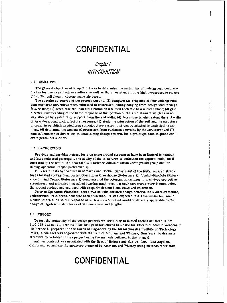
The general objective of Project 3.1 was to determine the suitanility of underground concretearches for use as protective shelters as well as their resistance in the high overpressure ranges(50 to 200 psi) from a kiloton-range air burst.
The specific objectives of the project were to: (1) compare t.ac response af four undergroundconcrete-arch structures when subjected to controlled Loading ranging from design !oad throughfailure load; (2) deter.nine the load distribution on a buried arch due to a nuclear blast; (3) gaina better anderstanding of the basic response of that portion of the arch element which is in noway affected by restraint or support from the end walls; (4) determine tc what extent the e,.d wallsof an underground arch affect its response; (5) study the interaction of the soil and the structurein order to establish an idealize, soil-structure system that can be adapted to analytical trea.-mene; (6) detei mine the amount of protection from radiation provideu by the structure; and (7)gain information cf direct use ia establibhung dtsign criteria for a prototype cast-in-place con-crete persc: -l sielt er.
1.2 BACKGROUND
Previous nuclear-blast-effect tests on underground structures have been limited in numberand have indicated principally the ability of the stiuctures to withstand the applied loads, as il-lustrated by the test of the Federal Civil Defense Administration urdo.'round group shelterduring Operation Teapot (Reference 1).
Full- scale tests by the Bureau of Yards and Docks, Department of the Navy, on arch struc-tures located 4boveground during Operations Greenhouse (Reference 2), Upshot-Knothole (Refer-ence 3), and Teapot (Reference 4) demonstrated the tDotential advantages of arch-type protectivestructures, and indicated that added benefits might esult if such structures were located belowthe ground surfacc and equipped .4ith properly designed end walis and entrances.
Prior to Operation Plumbbob, there was no substantiated design criteria for a hlast-resistant,underground, reinforced-concrate arch structure. ft was expected that a full-scale test wouldfurnish information 'on th. response of such a struct-re that would be directly applicable to thedesign of rigid-arch strurtures of various spans and lengths.
1.3 THEORY
To test the suitability of the design procedures pertaining to buried arches set forth in EM1110-345-4 3 to 421, entitled "The Deoign of Structures to Resist the Effects of Atomic Weapons."(Reference 5) prepared for the Corps of Engineers by the Massachusetts Institute of Technology(MIT). a contrict was negotiated with the firm of Ammann and Wtutney, New York. to design astructure to be tested in thi3 project using the methods outlined in that manual.
Another contract was negotiated with the firm of Holmes and Nax er. Inc., Los Angeles.California, to analyze the structure designed by Ammann and Whitney using methods other than
CONFIDENTIAL
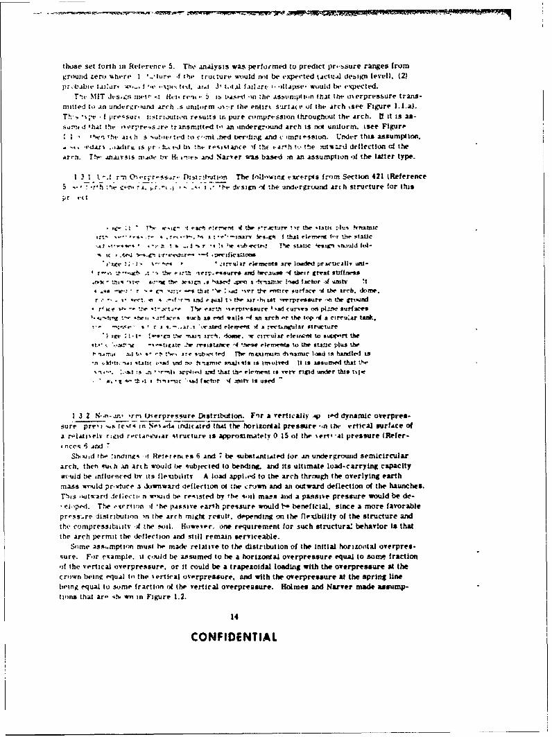
those set forth in Reference 5. The anAlysis was performed to predict pr--bsure ranges fromground zerv %there I -,liure 4 t h trutlure wtiuld not be expected tActu~d deaiicn level). (2)prtVabie lilhatt *a... I *wt -xv ted. Ai.. 3t tot4I faill .zr(4 *JIlAPSte wiuld be exp~ected.
T'ic MIT dvs..zit nwit -: kct rwt' .. 5 j. tiA!;rl on zhe .ismemnpiiSin that the olerpresbure trans-nu~dto An u dxeri~r''un Arch .s unittorm j%-,-r the erairt suriae of the Arch %see Figure l.I.a).
T!~' ~;t Ipro'isuri I.,strzoutinn resuits in pure corn'.prtssion throughotut the Arch. 11 it is as-sjrt ~d 'hAt !he iter; re.,s.re- !ransnutti-d t-' an ;inderground arch is nix uniorm. isee Figure
"inTt. ait h s ?a.i~ro c'mnt .. e ord.-g Ari c impt os non. this .oum.p£.
-u djx% -,acirr. is pr-t4.x t-d b% the re-i,'tance if :%t -Ar-h !t,* !the rttird drflection of theArrn. The- LnAivsis -nAtle 1w Ht -!ivs- and Sarver was base-d m An Assumption of the latter type.
1 3 1 L. -A r-n 0- r'r - csr t-io The itil]-w-ru eirt-rps from Section 421 (Reference5h .. n. -± 1w.- .o~n :,A *N'.a - dt-sipat 4~ thf- uralergrWzld Arlh structure !or this
Pr r(t
-1%.c t.g I eac* rtfrwro I tbw f*r~ture ?,r Ltc.111 :kaif.u NnatMic- . ~ -~- "~z '~ . srs v f (tht ceert f-r Ll. static
,at n * i at- .. 1 r -i 's ~wI'ecg. T~w Stine -t.-ign thuwad fol-
-~~~~ i-f- 'a-cuitar ekments are laided practicAliy ad-i -e rth2 &Me ber.rsaa2icuse -I their great $1.111nei
.? S ... u Oe ~isic a ',ase **n x 4tarnki t'ued factor af ufutT 14 40-v r CN -11 1.6121 '^* : -1ir tt-e MIrv ourlace -at the iarrI. d&me.r *' - cc-: 'i -, f -rn LMi futl t ie xir-titst re~rt-resr -ft the CT~IVix* 'ace Wt'. a .cae T~av cirt-lir ttsure I ad vur'es 0th pi--ne sutfM5~
4.a~t~ :- ae. r~wasuch is real -iiiso -4 in xrrh -r the top~ if a rirruzjr tAr.*
a-~ ~ ~ x;c a - i-.i.i\.ed rienwent At a rvcunigulAr striiCture
!c I i' tveCni I-w ntj- irli. '105w. ws cirruiar elttico't to si44~W'I theX'ug -'-tste ...W rrsastance -4 'n et eei to the staric pi"s the
I' l( !,. to - - tlw jr v~ abcK ted rhe maxiriwan duitamauc load is hamilt-I is4 k'atsatI v,,M' i -x) h'aarnc an i s i"Olved It Is assumed that t'Se
_ua-..3 s *r-oti;ai 'i.ed t at tI," re'ne-nt is '-.rv rigid uinder Ot i taeA.- a"- tt.t i inauc *.tad factor if itr io used
1 3 2 N.--m- iarm Vierprressure Di stribution. Fr a vertically V p td dynamic overpres-4 ure preti . tct-t in SetAdA indicAted tht the horizontal pressure -,n tflc ertical surfAce ofA r"A-iralv r~jcod r't-ta".cusar 4tructurr is appromwtety 0 15 of thi eri -cr1 pressure (Refer-
' cc 5 AadS.h-mxid ttw 'ineirts AI Retrnles 6 And ', be vubotantiAted for an undergrowid semicircular
arch. then -ruth an arth would b~e otubjected to bending. and its ultimate load-carrying capacitywvuld be inllu*,,ced bi' Its flelubaitv A load appi.ed to the arch thrrough the overlying earthmass would praxtuce a downward uleflection oi the cirjwn and an outward deflection o( the haunches.Thiaa itirar1 Jcf~ecip n wouid be re-tisted try tho -toil mass AMd a passive pressure would be de--el-Pod. The ritertion if 'he passive earth pressure would t- beneficial. since A more favorablepra-ss..re distribution in the arch migt result. dppendling on the nreidbility of the structure andthe compressibiiatv 1f the soil. Haows'cer one requirement for such structura: behavior is thatthe arch permit the deflection And still remain serviceable.
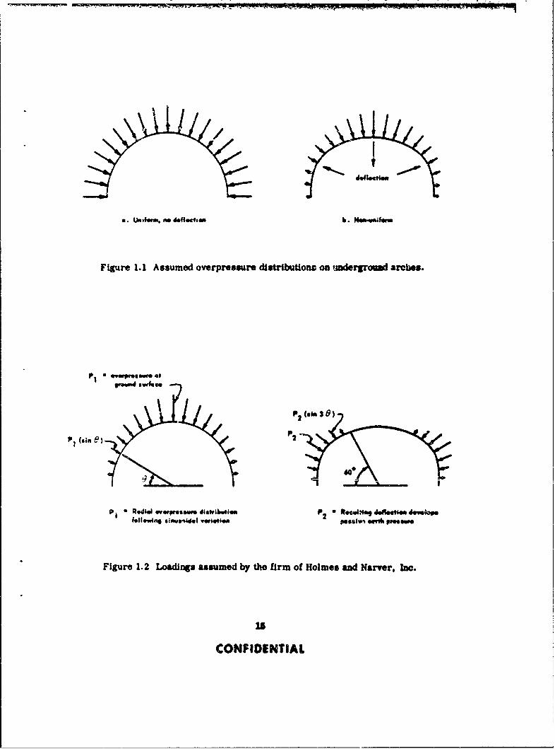
Scine sx.mpti'in must he made relative to the distribution of the Initial horitzontal overpres-s;ure. For extample. it could be assumed to be a horlitontal overpressure equal to some fractionoif the vertical oyerpressurr. or it could be a trapeztoidal loading with the overpressure at thecrown be4inR equal In the %ertical overpressure. and with the overpressure at the spring linebe-ing equal to some fraction nil the vertical overpreasure. Holmes and Narver made assump-tions that are 'aN. wiu in Figure 1.2.
14
CONFIDENTIAL
6. U1,1fom. no defloctla b. Nem-vwilem
Figure 1.1 Assumed overpressure diutritutlon on ,.mdergroaId arches.
esvd.m
P " RedaI wp.aaumdew disttibuea P 2 a fteo0.g doe~ 4040,ifellew4 Si"W~l vWm41 pmei elv" Pmesw
Figure 1.2 Loadings assumed by the firm of Holmes and Narver, Inc.
CE
CONFIDENTIAL
The following excerpts from the Holmes and Narver report (Reference 8) set forth the generalprinciples used in their presho' alysis of this project's underground structure:
"In the case of semicircular arches, the load de to overpressure is assumed toact ra,.all), folloAing a sinusoidal vaisation, with a imaximum intensity at the crownequal to the ovrp:,..Kure at the ground surface, and %%i'i zero intensity at the base.In addition to this 'primary' p, loa"Ing which might be regarded as being the loadpattern which %vld apopl, to a very rigid structure, a 'secondary' i load pattern iconsidered. intended to approximate the load due to pasive earth pressure developedin the region of outward deflection of the arch. This Is assumed as a radial sinus-oida, loading with maximum intensity p2 at 0t 30". z*tro Intensity at 0 - 60", andzero intensit at the base of the arch where - 01.
"The stabilizing effect of the p! loading is a function of the unknown soil character-istics and the flexibility of the arch
It was further stated that:
"Several types of areh failure are possible tsee Reference 9). An upper Ilmitingvalue of the collapsin ,,d would be obtained on the assumption that the loading is auniform radial pressure (The asiumption made In Section 421 of Reference 5.1Fpilure would then occur either by elastic Instability., or by a compression failure inthe matertal
.A second tvpe would be failure due to unsymmetrical loading resulting in highbendirg stresses accompanied by minimum thrust.
"A third type of failure would be a symmetrical loading condition producing a muchlower bending stress in coojunctio, with a high thrust.
"The tirst type of failure implies complete absence of bending stresses, giving acohiapairig preasure that is too high The second type of failure is not critical becauseof Its extremely transient nature This leaves the third type as the critical loadingcondition
"The load pattern arsumed to represent the critical loading condition is the slaus-oidal Wpe previously described.
"Under the loading. yield 'htngee' are assuried to occur in sufficient number toreduce the structure to a mechanism at failure In calculation of the static yieldresistance, allowance is made for the effect of axial thrust and the tribqutry earthmass on the period of vibration
These Holmes-Nar%er assumptions concerning the loading were used In their preshot analysisand have been refined in their postshot analysis. The refinements are presented In Appendix A.
N ICONFIDENTIAL

Chop/" 2
PROCEDURE2.1 TEST STRUCTURES
Four reinforced-concrete arch structures were tested during SbN Priscilla, all placedunderground with the top of the crown 4 feet below the ground surface. The four arches weresemicircular in cross section. with an Inside radius ci 8 feet and a thickness of 8 inches. Threeof the structures were 20 feet long. while the fourth was 32 feet long. The 32-foot-long structurewas included to assure an unrestrained section of arch essentially free of end-wall effects, sothat it could be determined how far and to what extent end walls affect arch action. This addedlength provided a favor able length-to-span ratio of two to one.
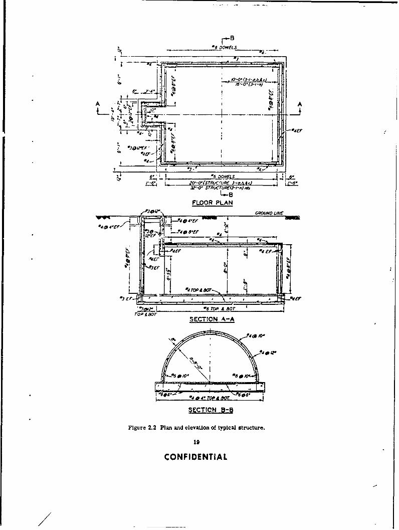
The 32-foot-long structure (3.1.n) and one of the 20-foot-long structures (3.1.a) were placedIn an area for which a ground-surface overpressure of 50 psi was predicted; the other two struc-lures were placed in areas for which overpressures of 100 psi (3.1.b) and 200 psi (3.1.c) werepredicted. The general location and shot geometry for the atrfuctures are shown in Figure 2.1;Figure 2.2 shows 'he plan and cross section of a typical structure.
For clarity, the following definitions pertaining to arches are presented as used in this re-port. Also see Table 2.1.
Springing line: Formed by the intersection of the arch with the floor slab.Crown: The topmost Part of the arch.Hauncl,: The sides of an arch between the springing line and the crown.Intrados: The inside surface of the arch.Extrados: The outside surface of the arch.Arch span: Horizontal distance from springing line to springing Line.
2.1.1 Design. The structural design was accomplished by the firm of Ammann and Whitneyunder Contract No. DA-22-079-eng-195. This contract stipiated that: (1) the structure beburied so that the crown would be 4 feet below the natural ground surface; (2) the arch be semi-circular; (3) the structure be designed to resist the effects of a 50-;al g d- surface air over-pressure resulting from the detonation of a 30-kt device 500 feet aboveground; (4) the compressivestrength of the concrete be 3.000 psi; and (5) the principles set forth in EM 1110-345-414 to 421tReference 5) be followed. The results of the design accomplished by Ammann and Whitney arecontained in Reference 10.
The procedure in the manual dictated a very thin arch to resist the transient load, but inorder to provide a structure suitable to resist both static and transient loads, a thicker archwas selected. The final structure was intended to be a standard-type structure that could beused by the armed services if it proved satisfactory in a ful-scale test.
Although Section 421 of Reference 5, which concerns below-ground structures, specifies adynamic load factor of one, Ammann and Whitney elected to use a dynamic load factor of two,basing their decision on the discussion in Section 420 of Reference 5, which concerns above-ground arches.
Ammann and Whitney computed the overpressure load per linear foot of arch length by multi-plying: design overpressure times dynamic load factor times arch span.
Total load = 50 x 2 x 144 X 16.67 a 240,000 lb/ft
The load at each reaction would then be:
17
CONFIDENTIAL

PLAA
PRRDITEDCTEDkACUPEA OVERPRESSURE(AUL)3. v
PAK-OVTERPRESSURE_
/3601
F/040' ado__________w-GROUND SURFACE
3.a &L3.1.n q- 3 . 1. b d 3 .1 -c
ELEVATION
Figure 2.1 Project plot plan.
18
CONFIDENTIAL
*6 DOWELS
A' A* 4E
4 "-
.4.-
tfit
LA~
FLOOR PLAN
SECTION SINE
I / -! ,0dl /0-
SE CTION A-A
Figure 2.2 Plan and elevation o! ty.pical structure.
19
CONFIDENTIAL-
/
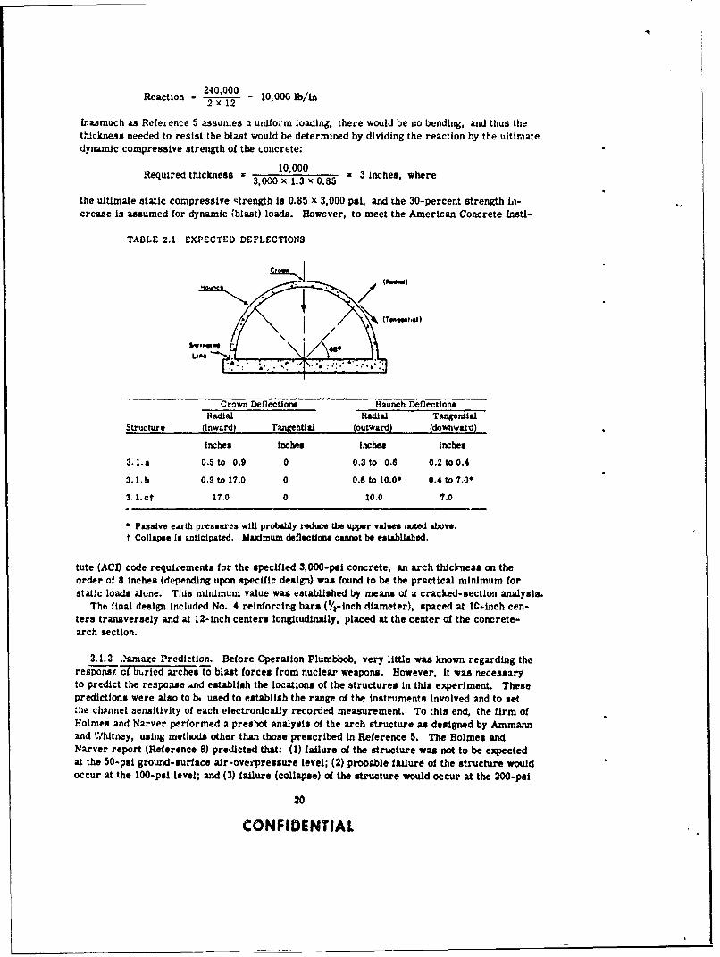
240,000Reaction 24 00 - 10,000 ib/in
2 x12
Inasmuch as Reference 5 assumes a uniform loading, there would be no bending, and thus thethickness needed to resist the blast would be determined by dividing the reaction by the ultimatedynamic compressive strength of the -oncrete:
10,000Required thickness =300 x 1.3 085 = 3 Inches, where
the ultimate static compressive strength is 0.85 x 3,000 psi, and the 30-percent strength hi-crease is assumed for dynamic iblast) loads. However, to meet the American Concrete Insti-
TABLE 2.1 EXPECTED DEFLECTIONS
Crown Deflections Haunch DeflectionsRadial Radial Tangential
Structure (inward) Tangential (outward) (downward)
Inches inches inches inches
3. l.a 0.5 to 0.9 0 0.3 to 0.8 0.2 to 0.4
3.1. b 0.9 to 17.0 0 0.6 to l0.00 0.4 to 7.00
3.1. ct 17.0 0 10.0 7.0
Passive earth pressures will probably reduce the upper values noted above.t Collapse Is anticipated. Maximum deflections cannot be established.
tute (AC!) code requirements for the specified 3 ,000-pei concrete, an arch thickness on theorder of 8 inches (depending upon specific design) was found to be the practical minimum forstatic loads alone. This minimum value was established by means of a cracked-section analysis.
The final design included No. 4 reinforcing bars (/-inch diameter), spaced at iC-inch cen-ters transversely and at 12-inch centers longitudinally, placed at the center of the concrete-arch section.
2.1.2 ..amace Prediction. Before Operation Plumbbob, very little was known regarding theresponsu cf buried arches to blast forces from nuclear weapons. However, it was necessaryto predict the response ,nd establish the locations of the structures in this experiment. Thesepredictions were also to b, used to establish the range of the instruments involved and to setthe channel sensitivity of each electronically recorded measurement. To this end, the firm ofHolmes and Narver performed a preshot analysis of the arch structure as designed by Ammannand Whitney, using methods other than those prescribed in Reference 5. The Holmes andNarver report (Reference 8) predicted that: (1) failure cd the structure was not to be expectedat the 50-psi ground-surface air-oves pressure level; (2) probable failure of the structure wouldoccur at the 100-pal level; and (3) failure (collapse) of the structure would occur at the 200-psi
20
CONFIDENTIAL

level. The estintated displacement along the center portion of the armhes of the structures atthe thre, pressure levels is shown in Table 2.1.
The general principles used in the Holmes-Narver preshat analysis were given in Section1.3.2. An important conclusion reached by Holmes and Narver was that:
"In the case of the arch-type structures, it is evident that soil characteristicshave an important effect on ultimate strength and that proper compaction of thebackfill around the sides of the arch is essential for maximum strength."
To obtain a better understanding of the behavior of a buried arch in the plastic range and todetermine the ultimate mode of failure of the arch, three one-eighth-scale models of the archused in this project were tested a the U. S. Naval Civil Engineering Laboratory (NCEL). Geo-metric similitude was maintained between the model ,ma the prototype; however, because of thesmall scale, no attempt was made to maitain similitude of the unit weight of the concrete.Graded sand was used in the concrete mix for the model, and the design strengths of the con-crete were the same as had been specified for the prototype. Small steel wires were used tosimulate the reinforcing steel. Soil cover was provided by sand which had been passed througha No. 10 sieve.
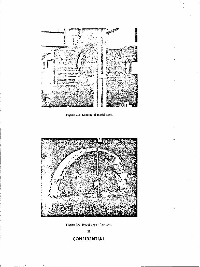
For convenience, the width oi the arch segment was limited to 4 V/2 inches. A reinforced ply-wood box housed the model and the sand cover. Static loads were applied to the sand cover bya hydraulic jack and steel beam, as showu in Figure 2.3. In order to reduce the frictional re-sistance of the sand on the plywood during loading, two layers of plastic-impregnated paper(well greased) were placed on all inner surfaces of the plywood box.
Three arch segments were tested, one with floor slab and two without floor slab. Soil-pressure gages placed at the springing line indicated that the loss of vertical pressure throughthe soil mass varied from approximately 55 percent at 20-psi applied load, to 45 percent at 50-psiload, and 30 percent at 130-psi load. This loss was presumably a transfer of pressure to thesides of the box through friction and was not considered of much importance in qualitative testsof this type.
Figure 2.4 shows the arch segment with the floor slab, after sustaining an applied static loadof 175 psi. The crown of the arch and the floor slab cracked at 50-psi applied load. The Initialcompression failure of the concrete arch occurred at one springing line at about 110 psi, and atthe opposite springing line at 130 psi. Failure of one side occurred at 140 psi and failure of theother side at 170-psi applied load; extreme cracking and spalling of the concrete accompaniedthese failures. It should be emphasized that these loads were applied to the surface of the sand,and that the actual loads on the arch segment were probably less than the above-mentioned values.
The arch deflection at maximum load was approximately % inch; permanent set after removalof the load was !/I inch.
Based on a static analysis of the stricture (assuming a nonuniform pressure distribution' andon results of the model tests, the NCEL prediction of structural behavior of the arch section upto the design load (50 psi) was as follows:
At a dynamic overpressure of approximately 10 to 15 psi, the moment-carrying capacity ofthe arch will be exceeded at the springing line. Since the reinforcing steel will be stressed be-yond the yield point, there will, in effect, be plastic hinges formed at the springing line. Duringthe next phase the structure will act as a two-hinged arch, and because of the stiffness of thearch the deflection will be small. At approximately 25- to 35-psi overpressure, assuming asymmetrical loading, additional plastic hinges will form at the crown and at the hiunches, re-suiting in a 5-hinged arch mechanism. Failure of the structure is prevented by the buttressingeffect of the soil against the outward deflection of the haunches. At the 50-psi design overpres-sure level the arch will show evidence of permanent deflection due to the plastic deformation atthe critical sections. On the intrados of the arch, tension cracks will be apparent at the crown,and compression failure will be apparent at a point on the arch about 25 degrees up from thespringing line. Although the arch T ill be serviceable after receiving a blast load of 50 psi,plastic hinges will have formed at the five critical sections. I Is evident that considerable plas-
21
CONFIDENTIAL
*A %
:
41 -
4 4'
Uq 4AA,
Figure 2. 3Modta odel arch trts.
22
CONFIDENTIAL
tic deformation will occur before a uniform pressure distribution can be realized. With an asym-metrical loading of any great magnitude on the arch, considerable structural damage could occurduring this test because of the small steel ratio of one-half of one percent.
2.2 CONSTRUCTION AND MATERIALS
The four structures were constructed by the general contracting firm of Lembke, Clough, aadKing of Las Vegas, Nevada. Holmes and Narver acted as the architect-engineer for the AtomicEnergy Commission and provided construction-inspection services for all projects. The entireconstruction time for this project was about three months. The excavation for the four struc-tures was completed early in March 1957, the structures were completed by 12 April 1957, andthe backfill operation was completed by 4 June 1957. (See Appendix G for specifications and as-sociated design drawings used in conjunction with the construction program.)
2.2.1 Soil Properties. Prior to the field operation, laboratory tests were performed as apart of Project 3.8, Soils Survey, on both undisturbed and remolded samples of soil obtainedfrom the general vicinity of the site where the structures were to be located. The soil in thearea had a uniform appearance and textur!, and can be genorally classified as clayey-silt. Theresults of compaction tests, Atterberg limits tests, and mn..hanical analyses on the natural soilat varinu, depths are shown in Figure 2.5.
In an attempt to duplicate the compressibility characteristics of the natural soil, a series oftests were performed on samples of remolded soil of various water contents, using three dif-ferent compaction etforts. Test specimens were prepared from the mold camples, and a con-fined compression test was performed in a consolidometer apparatus. A tangent modulus ofdeformation was established from the test data; based on analysis of the data, the backfill ma-terial was recommended to be placed at 100 percent standard AASHO density, with a water con-tent 3 percent less than optimum. The resulting recomm, - 4 ed and as-placed values of drydensity and water content for the backfilled soil necessary to duplicate the modulus of compress-ibility are given in Table 2.2 along with values for the undisturbed natural soil located adjacentto the backfill areas.
Shortly after the backfilling operaticn was completed, undisturbed soil samples were obtainedfrom both the backfill and the adjacent natural soil at depths of 4 and 10 feet at the four stations.Samples were obtained in the backfill after the shot also, but no strength tests were made sincethe results fr'm the preshot and postshot density and water-content tests showed no significantchange and thus no change in the postshot strength characteristics of the material (see Table 2.2).The compressibility of the compacted backfill was about equal to th," of the natural undisturbedsoil when compared by means of similar *ests, i. e., consolidation tests, constant ratio of appliedstress triaxial tests, and soniscope tests, as shown in Table 2.3. The compressive modulus forthe compacted backfill as determined by the soniscope test is lower than that for the natural soil,which may be due to test conditions. The natural soil samples were encased in 3-inch-diametersteel tubes when subjected to sordscope tests whereas the undisturbed record samples were en-cased in 6-inch-diameter cardboard tubes. The difference in tubes may have had a marked ef-fect on the transmission characteristics of the samples. (For a detailed description of thevarious soil properties and associated tests, see the report of Plumbbob Project 3.8, Refer-ence 11.)
2.2.2 Construction-Material Properties. Type II portland cement was used in the constructionof the concrete arches. The aggregate was pit run, screened, and stockpiled at the FrenchmanFlat area; the maximum size of coarse aggregate was approximately 2 inches. A mechanicalanalysis of the sand indicated that the grain sizes ranged from a No. 4 to a No. 200 U.S. standardsieve size. A summary of the proportions used in the concrete mix design for the four structuresis shown in Table 2.4.
Thirty standard concrete cylinders (compressive strength specimens) and ten concrete beams(flexural strength specimens) were obtained from each structure for laboratory tests which es-
23
CONFIDENTIAL

F j , , I I tI.... •7J'.1,
. . . . . .. . . . .
. . . . . . . 0
IIb
r i
LIL
. . . . . . . . . , • * 4".-
.t-. 4- .- z
AO *.-: -
0 z
A , I ,4
,a
-7
±44013Mi noU~ AUG ±33dA J~- - - '' --j---'
--- 0 . -
2r4
CONFIDENTIAL
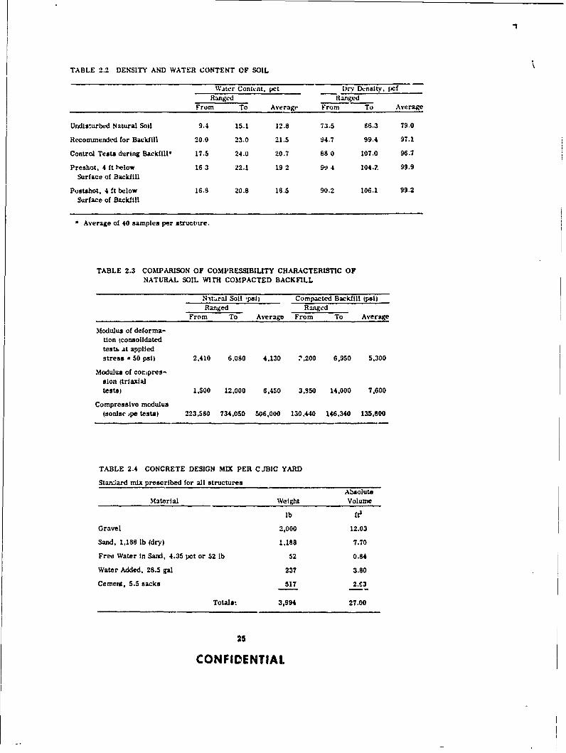
TABLE 2.2 DENSITY AND WATER CONTENT OF SOIL
W.ter Content. pct Dr D.nsity. pcfRanged Rangkd
From To Average From To Average
Undis:urbed Natural Soil 9.4 15.1 12.8 73.5 86.3 79.0
Recommended for Backfill 20.0 23.0 21.5 94.7 99.4 97.1
Control Tests during Backfill" 17.5 24.0 20.7 88 0 107.0 96.7
Preshot, 4 ft below 16 3 22.1 19 2 90 4 104-. 99.9Surface of Backfill
Pustshot, 4 ft below 16.8 20.8 18.5 90.2 106.1 99.2
Surface of Backfill
Average of 40 samples per struct-tre.
TABLE 2.3 COMPARISON OF COMPRESSIBILITY CHARACTERISTIC OFNATURAL SOIL WItH COMPACTED BACKFILL
Ntt.ral Soil ,mi) Compacted Backfill (pai)Ranged Ranged
From To Average From To Average
Modulus of deforma-tion (consolidatedtests at applied
stress = 50 psi) 2,410 6.080 4.130 ",200 6,950 5.300
Modulus of cor.pres-sion (trtaxialtests) 1,500 12,000 6,450 3.950 14,000 7,600
Compressive modulus(sornsc ,pe tests) 223,580 734,050 506,000 130.440 146.340 135.800
TABLE 2.4 CONCRETE DESIGN MIX PER CJBIC YARD
Standard mix prescribed for all structuresAbsolute
Material Weight Volume
lb fte
Gravel 2,000 12.03
Sand, 1,188 lb (dry) 1,188 7.70
Free Water in Sand, 4.35 pet or 52 lb 52 0.84
Water Added, 28.5 gal 237 3.80
Cement, 5.5 sacks 517 2.43
Totals: 3,994 27.00
25
CONFIDENTIAL

tablished 7-day 28-day, and shot-time strengths. The tops of the cyl:-" !er specimens werecovered immediately alter they were prepared. All the exposed surfa~eb of the specimens andstructures were sprayed with Hunt's curing compound. The various specimens were placed onthe ground surface near the appropriate structure.
Shortly aiter the forms werE stripped from the various structures, half of the specimens tobe tested at shot time were removed from the molds and allowed to cure Ir 'he open. WhLn thestructures were backfilled, the specimens that had heen removed from the molds were coveredwith the same backfill material in an attempt to simulate the curing condition experienced bythe various structures. Y he remaining specimens t7-day. 28-day, and the remaining shot-timespecimeno) were removed from the molds In the testlng labo:at -ry. All of the shot-time speci-mens were sent to tne testing !aboratory one munth p:ior to the Priscilla event.
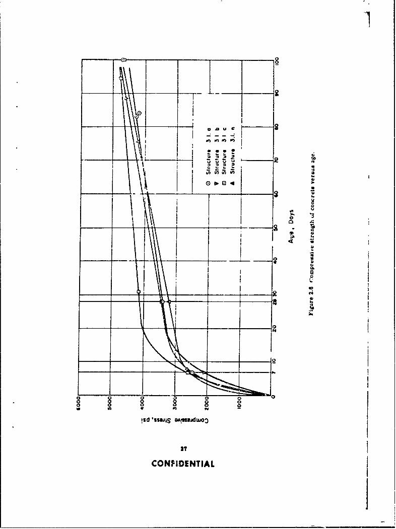
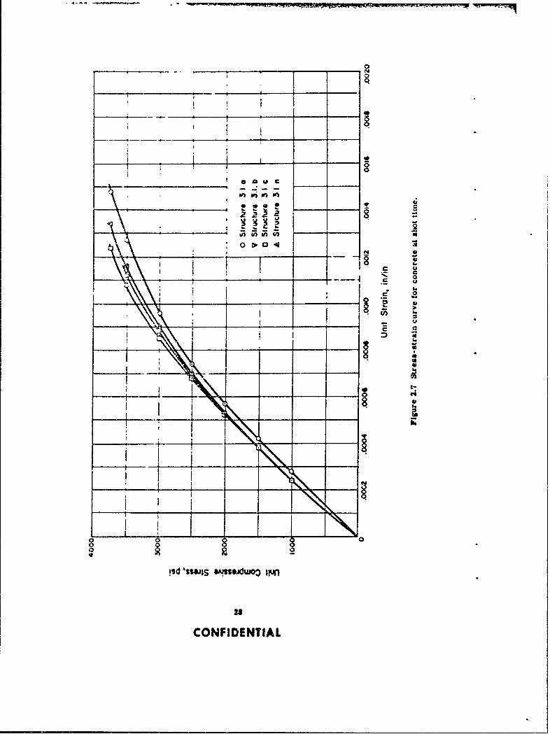
The laboratory tests, conducted by the Nevada Testing Laboratory. Ltd., Las Vegas., Nevada,consisted of determning tl.e compressive strengths, flexural strengths, and static moduli ofelasticity of the concrete specimens at various times after the structures were poured. In addi-,.on to these tests, %.alues of the dynamic modulus of elasticity at shot time were. 1"termlned forseveral of the specimens by personnel of the Concrete Division of the Waterwayb h. erimentStation (WES). Tests to determine the static modulus of elasticity were performed on the cylinderspecimens, while the dynamic tests tnondestructive) were performed on the beam specimens inorder to take advantage cf the additional length-thus increasing the reliability of the results.Dynamic modulus of elasticity was calculated by using procedures outlined by the American So-ciety for Testing Materials ( ASTM Designation C215-55T). Several specimens were tested atthe end of seven days to determine if the concrete '.ad attained sufficient strength to allow theremoval of forms. The other specimens were tested at 28 days and U the time of the Priscillaevent. The results of all tests indicating the compressive strength values with respect to agefor each structure are shown in Figure 2.6. Four curves of average stress vers'is strain forthe concrete specimens obtained from tne various arch sections and tested at shot time areshown in Figure 2.7. The results of the concrete strength tes!s at the time of the Priscillaevent are shown in Table 2.5.
In addition to the above specimens, NCEL personnel prepared three compressive and threeflexural strength specimens from both the base slab and the arch of Structure 3.2.n. Thesespecimens were removed from the molds when the forms were stripped from Structure 3.1.n,stored on the floor slab for curing purposes, and tested at shot time. The results of these NCELtests are included with the strength resulte shown in Figures 2.6 and 2.7.
Intermediate-grade billet steel was used exclusively as the reinforcing material in the variousstructures. Ten sample reinforcing bars of 13-inch length were taken for each of the three sizesused (Nos. 3, 4, and 6). AI bars from each group were tested for ultimate strength, percentageof elongation, and stress versus strain into the plastic range. The tests on the reinforcing-barspecimens were performed at NCEL; results of these tests are shown in Table 2.6.
2.9.3 Construction Methods. A backhoe was used to excavate the four areas. The soil prop-erties were such that the contractor could utilize vertical excavations, thereby necessitating amlz.imum of excavation effort. The sides of the excavation were approximately 2 feet from thesides of the base slabs of the various structures, and the floor of the excavation was level towithin t 4 inch.
Concrete materials were combined in a portable, central batching plant tdjacemt to WaterWell 5b (Frenchman Flat), 2 miles from the construction area. Bulk cement was used andwas stored In a portable hopper that weighed the amount of cement required per batch of con-crete. A portable batching plant (Travel Batcher) was used to hold and weigh the cement, sand,and gravel. The cement, aggregate, and water were poured into the mixing trucks (5-cubic-yard capacity) simultaneously.
The base slabs for ali of the structures were poured first. The steel in the base slab wasplaced according to plan, except that the top reinforcing bars were inadvertently placed oneinch lower than was specified. (See Figure 2.8 for typical placement of reinforcing steel in a
28
CONFIDENTIAL
ED~ 8
*1 2
see
go..
0
0
8
88
!sd 'swjS qM" "
isd ~~a~s 27
CONF~IDENTIAL
0
- 1 -N . .
WIN
- ___ ____ ____ _ __ __ _ __to
sdS I - -W
33 nInI
COFIENIA
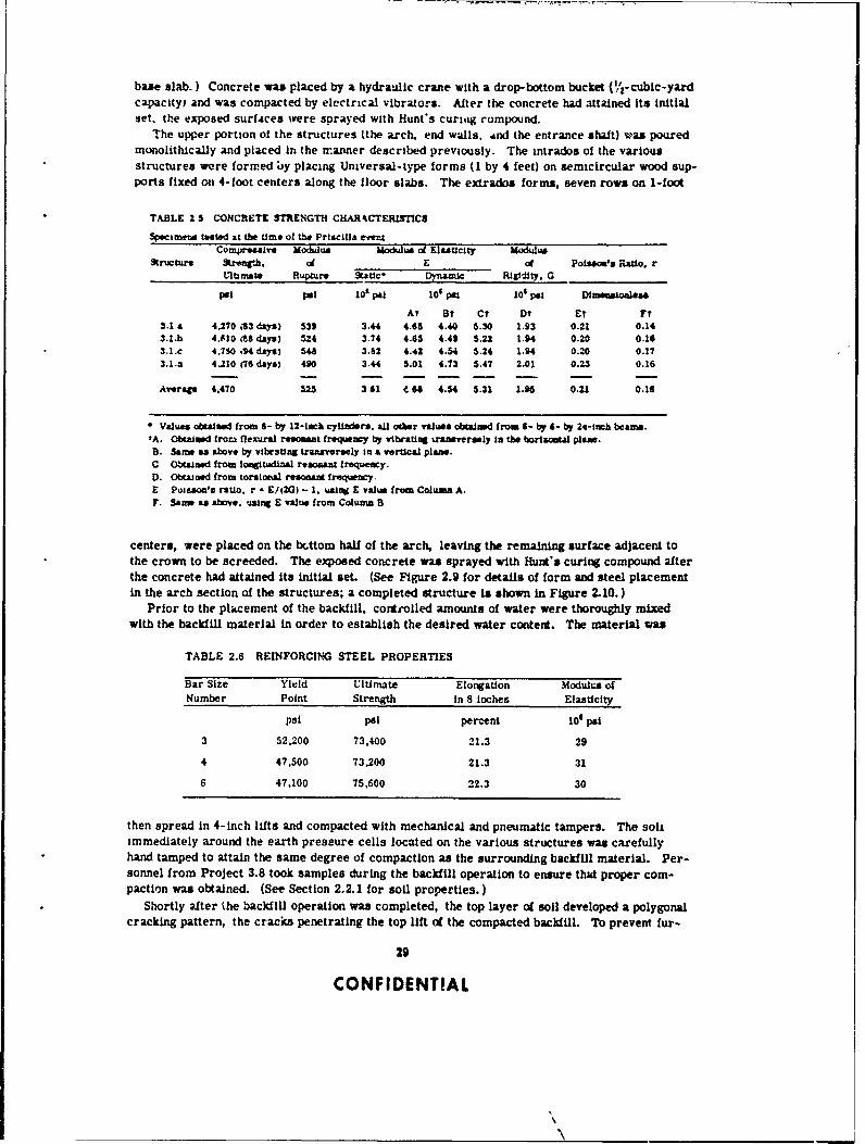
base slab.) Concrete was placed by a hydraulic crane with a drop-bottom bucket (V2-cubic-yardcapacity) and was compacted by electrical vibrators. After the concrete had attained its initialset. the exposed surfaces were sprayed with Hunt's curi1tg compound.
The upper portion of the structures (the arch. end wails. And the entrance shalt) vas pouredmonolithIcally and placed in the manner described previously. The intrados of the variousstructures were formed by placing Universal-type forms (1 by 4 feet) on semicircular wood sup-ports fixed on 4-foot centers along the floor slabs. The extrados forms, seven rows on 1-foot
TABLE 2 5 CONCRETE STRENGTH CHAR4CTERISTIC$
Specimens tested at the time of the Priscilla eve=Comp sive Modlus Mlodulus of Elasticlty Modulus
9ructurv tzWr1n.h. of E of Poson's Rtio. rltrlmae Rupture Sttic- Dynaznc Rigidity. G
psi pi low 0 iO'sp 109ps Dimensionless
At Bt Ct Dt Et Ft3.1 a 4.2T0 3 day) 539 3.44 4.65 4.40 5.30 1.93 0.21 0.143.1.b 4.fl0 M8 days) 5.4 3.74 4.65 4.41 5.22 1.94 0.20 0.163.1.c 4.730 .14 day) 54 3.62 4.42 4.54 5.24 1.94 0.20 0.173.1.3 4.210 (76 days) 490 3.44 5.01 4.73 5.47 2.01 0.23 0.16
Averat 4.470 525 341 4 " 4.54 5.31 1.96 0.21 0.16
Values obtUiasd from 6- by 12-tmak cylindesr. all oier valus obtained from 6- by 4- by 24-inch beams.'A. Obtained frora flexural rasomat frequency by vibrating uW bversely in the borisontal plans.
B. Same as above by vibrstiag transversely in a vertical plans.C Obtained from lagitudinal resonant frequency.0. Obtained from torsionsl resonant frequency.E Pojisoa's ratio. r - 9/(2G) - 1. us4ag £ value from Column A.F. Sam as above. 0511W E value from Column B
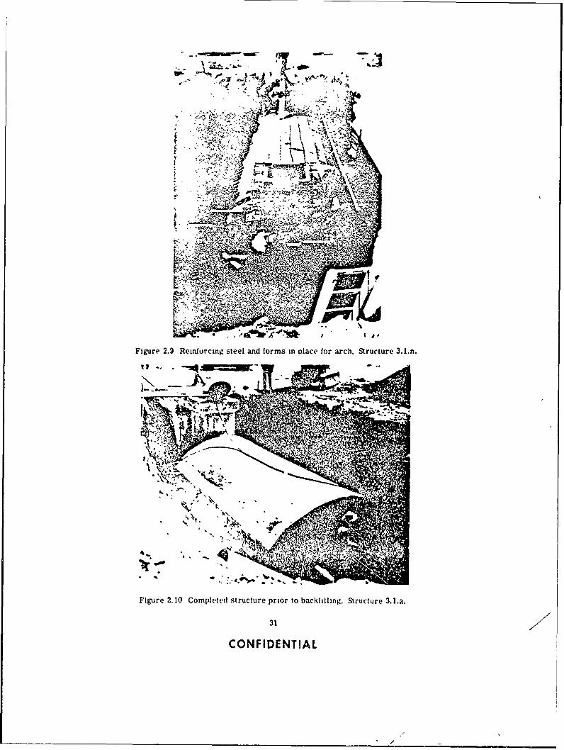
centers, were placed on the bcttom half of the arch, leaving the remaining surface adjacent tothe crown to be screeded. The exposed concrete was sprayed with Hunt's curing compound afterthe concrete had attained its initial set. (See Figure 2.9 for details of form and steel placementin the arch section of the structures; a completed structure is shown in Figure 2.10.)
Prior to the placement of the backfill, controlled amounts of water were thoroughly mixedwith the backfill material in order to establish the desired water content. The material was
TABLE 2.6 REINFORCING STEEL PROPERTIES
Bar Size Yield Ultimate Elongation Modulu's ofNumber Point Strength in 8 inches Elasticity
psi psi percent lO psi
3 52.200 73.400 21.3 29
4 47.500 73.200 21.3 31
6 47,100 75.600 22.3 30
then spread in 4-inch lifts and compacted with mechanical and pneumatic tampers. The soilimmediately around the earth pressure cells located on the various structures was carefullyhand tamped to attain the same degree of compaction as the surrounding backfill material. Per-sonnel from Project 3.8 took samples during the backfill operation to ensure that proper com-paction was otained. (See Section 2.2.1 for soil properties.)
Shortly after the backfill operation was completed, the top layer of soil developed a polygonalcracking pattern, the cracks penetrating the top lift of the compacted backfill. To prevent fur-
29
CONFIDENTIAL
,% t: vr ami( v, % rt tI %I! h I a . x6 I .1 i 4 '. it % *. I . ,
2 J ME-REE :
lo*. 1ti i hutIIn m j~1 .I; I ,.I *.d a. III ~I. I(' I i It'A-, ( Ii It* I .I Z. ar Obtaining 'atrut, picturt. -l t(ho pi . i.n.. : ::.: '11 .z .'i I stil hi t c: i tIos conditiomns
is efInphic'ated m~ .1. :.,t. r''. ut. *: it :1, i P!a i,i at. ch an id the conipre'ssibility of
-,4:- -
'S,'
Ficure 2.8 Floor slab) prior to pouring concrete. Structure 3. l.c.
the soil. Previous reports (Reht rentirs 6 and 71 Indicate that for Nc~ ada Test Site soil the aver-age lateral pressure onl a terti al wall oh an underground rectangumlar structure subjected to anuclear blast ib approxmatc-1v 15 pt.rccnt as g~reat lin m..i~nitude as the pre ssure applied at theltp surlace ol the bo~il hIn' dt-pth., dI eart h e'oier oh up to 8 tet. This infurmiation is not directlyapplicable to arch struclurv',. hoike~er. since the' arch defle( tjien Uifcctb the soil pressure,Therefore. attempts %ert- madle in this im~ebt igat ion t( dviernme the load dimtribution on thearch.
In addition to, a know ledge ',I the. loading condhit ions. proper dt-Nige of a st ructure depends onan understanding of its ,t ructural utc'ha. ir under the applied loads. Since irdormnation on theresponse oh an urnderricnd arc I structure subjected to las~t loading is meager. responsemeasurements w'ere' til:o obtaine-d ior these, structures.
2.3.1 Inst rumentat ion. Inst runat ion of thle !our structures oh this project included bothelect ron ic a e'cte-n i I nd uid chan i al tat' t- re coring~i hymtemis. Electronic measo C -
ments were made of transient air oterprebssures. deflettions. acce'lerations. earth pressures,and strains; mechanical mevasuremients were made oh air ov'erpressures and deflections. TheBallistic Research Laboratorwab (Pirojec~t 3.71 accomplished the instrumentation for Structures3.1.a. b. and c: bor a dtilud des-cription of this work refer to Appendixt B. The NCEL accom-
30
CONFIDE NTIA L
:v.
'57
f-~ - kr_
Jul-'
-
Fiur 2.9 Renfrcn ste n om n l o rh Srcue31n
UAW
Figure 2.0 Copleted steltand forms tn oace for arch Structure 3.1..
31
CONFIDENTIAL
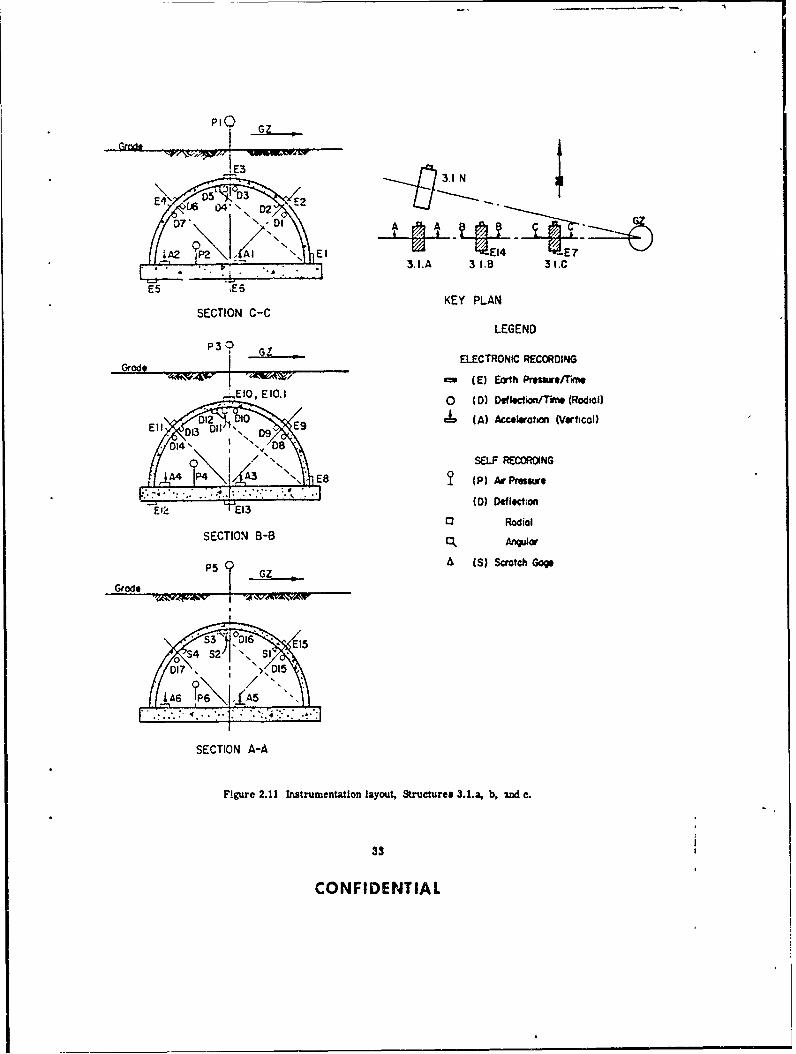
pllshed the Instrumentation fcr Structure 3.1.n; for a dotailed description of this work refer toAppendix C. The general Instrumentation layout, including gage identiicatlon for the fourstructures, is shown tn Figures 2.11 and 2.12.
In order to determine the degree of radiation prote tion afforded, a.1 four itructures wereinstrumented with gamma flim badges and neutron chemical dosimeters i tMe Chemical War-fare Laboratory (Project 2.4). A description of this work is presented in Appendix D.
A possibUilty existed that the severe ground shock would spall the inside surfaces of thestructure, thereby creating missile (chips or fragments of concrete) hazards. To determinethe quantitv 2nd size ,! thb z1Lissiles, Styrufoam mizaile Lraps were Installed In all of thestructures by the Lovelace Foundation (Project 33.2). In addition, dust collectors were placedi the four structures to determine if the ground shock would cause dust on and within the con-
crete walls to spill into the structure. A description of this work can be found in Appendix E.The instrumentation utliz d is listed in Table 2.7. Figures 2.13 through 2,16 show the over-
all layout of the recording instr ments in the four structures, as well as a view of the interiorof the structures.
To determine the effect of irradiation on different types of photographic paper and film usedin electronic recording, four types of recording paper and one type of film were exposed tovarious intensities of radiation. Results are presented in Appendix F.
2.3.2 Damage Survey. The damage survey consisted of level and transit surveys, photo-graphs, and a visual inspection.
A level and transit survey was performed after the structures were completed, and prior tothe backfilling. Identical surveys were also performed both prior to and ater the shot in orderto determine the relative permanent deflections and movements caused by the ground-surfaceair overpressure.
Photographs and visual inspections of the structures were made before and ater the shot torecord visible damage and also to aid in the interpretation of instrumentation results.
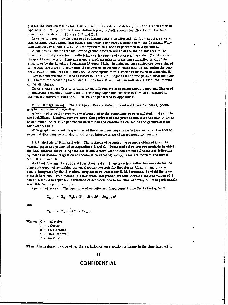
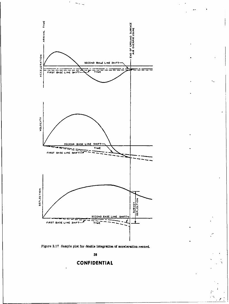
2.3.3 Methods of Data Analysis. The methods of reducing the records obtained from thevarious gages are presented in Appendices B and C. Presented below are two methods in whichthe final records shown in Appendices B and C were used to determine: (1) transient deflectionby means of double-integration of acceleration records; and (2) transient moment and thrustfrom strain records.
Method Using Acceleration Records. Since transient deflection records for thebase slab were not available, the acceleration records for Structures 3.l.a, b, and c weredouble-integrated by the 0 method, originated by ,32rofessor N. M. Newmark, to yield the tran-sient deflections. This method is a numerical integration process in which various values of 8can be selected to represent variations of accelerations in the time itterval, h. I is particularlyadaptable to computer solution.
Equation of motion: The equations of velocity and displacement take the following form:
Xn+i = Xn+Vnh+(/z- ) nhz + On+Ih2
and
Vn+t =Vn+ (an+an+i)
Where: X = deflectionV u velocitya = accelerationh a time interval
= variable
When j is assignEd a value of %, the variation of acceleration Is linear in the time interval h,
32
CONFIDENTIAL
1E3
SETO C-
LEGENDP39 GZ ELECTRONIC RECORDING
C= E) Earth PreseiwIrmn.EbO, EIO.: 0 (D) Deflection/Tm'.e (Rodial)
El 1 L10 J-E (A) Acceleration (vertical)
A4 ~4 : A3\ EBSELF RECORDING, .3 E (P) Ar Pmranur
F.Ia E13(D) Deflection
SECTION B-B Arquor
P5 GZ (S) Scratch Goge
Grade
SECTION A-A
Figure 2.11 Instrumentation layouit, Structures 3.1.a, b, and c.
33
CONFIDENTIAL

ao 0 o07 a 0 -- ~ --
EKEY PLAN
F 1 SECTION D-D LEGEND
P7 ELECTRONIC RECORDING
(E) Earth Pressure/Time
E21 .E2. (P) Air Prussure/TimeE23 A. 19 (D) Detlactior/Time
E2 8 0-0 HorizontalE251 E1 E? Vertical
cf(A) Acceleratim (Verical)- .E6 - (S) Strain
SECTION E-E SELF RECORDING
(D) Deflection
GZ C3-. a Horizontal
Vertical
SCION F-F
S1igure 29.12,7 mnttalyot tutue31n
D21 23/
CON\2ENT1A
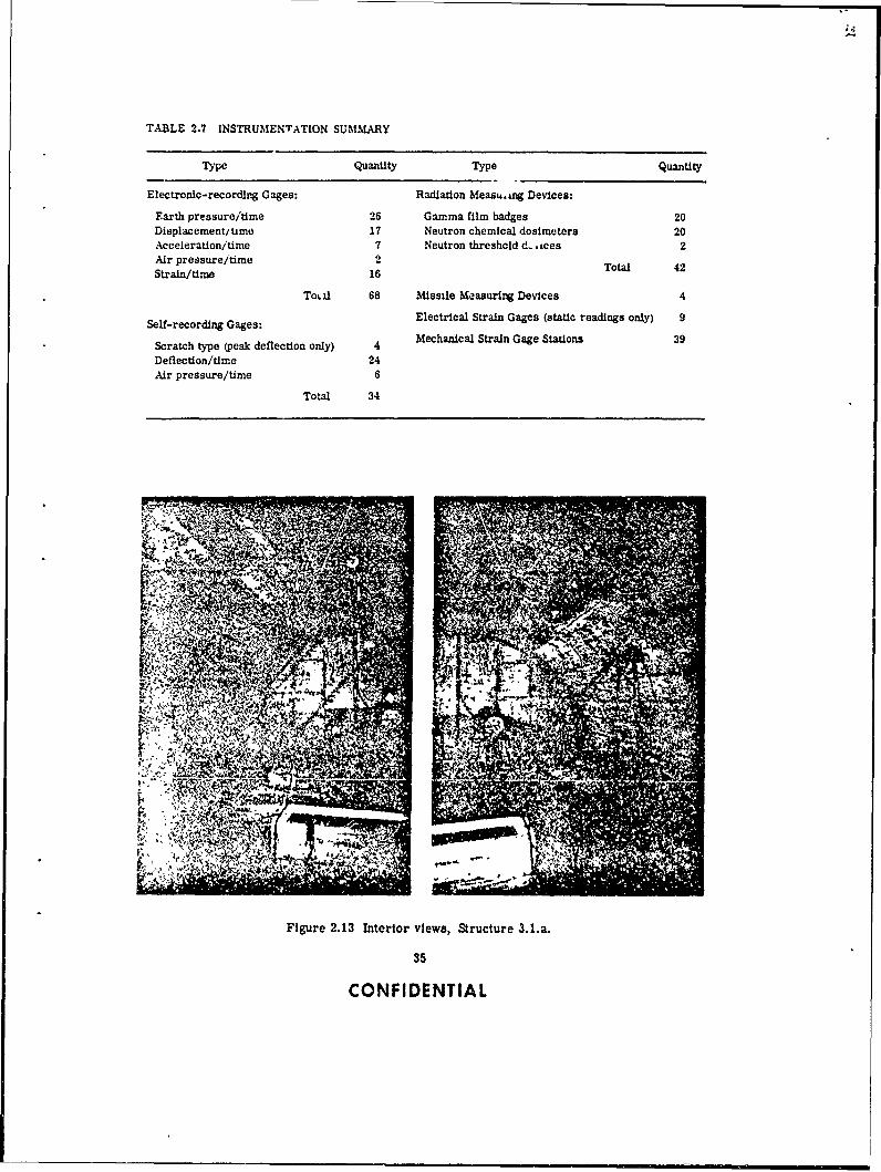
TABLE 2.7 INSTRUMENTATION SUMMNARY
Type Quantity Type Quantity
Electrontic-recording Gages: Radiation Measu.4ng Devices:
Earth pressure/time 26 Gamma film badges 20Displacement/ time 17 Neutron chemical dosimeters 20Acceleration/time 7 Neutron threshold d- ices 2Air pressure/time 2 Total 42Strain/tirne 16
Tot il 68 Missile Measuring Devices 4
Self-recording Gages: Electrical Strain Gages (static readings only) 9
Scratch type (peak deflection only) 4 Mechanical Strain Gage Stations 39Deflection/time 24Air pressure/time 6
Total 34
Figuzre 2.13 Interior views, Structure 3.1.a.
35
CONFIDENTIAL

• . I . v , ,. . •. o
.. .. S . -
Figure 2.14 Interior views, Structure 3.1.n.
and the deflection equation becomes
Xn i n- n 3tiz C , I h2
Since records from accelerometers are subject to baseline shifts, the records show in Ap-
pendix B were corrected using a method Suggested by D. C. Sachs If Staor Reercnsiue
This method assumes that no acceleration for underground st,cue ofccunfrdsReserc d ( dIstiue
at which the positive air pressure phase ends) and therefore that the velocity remains constantthereafter. Since the accelerumeter was found stationary, this constant velocity must have been
38
CONFIDENTIAL

4,4
V L ~ $'
~~4-,
V~ 4 41
A All
Figure 2.15 Interior views, Structure 3.1.b.
4Is A"
AllA
Figure 2.16 Interior views, Structure 3.1.c.
37
CONFIDENTIAL
'6I
OLiI- 4
I-J
F IRST BASE LINE S1T TIMEU
0-j
tSECOND BASE LINE SHIFT-%
FIRST BASE LINE SJI7T ---
z0
. 0
SECONO BASE LINE. SHIFT-7
rIAST BASE LINE 3NIF11? T I M
Figure 2.17 Sample plot for double integration of acceleration record.
38
CONFIDENTIAL
zero. If the first integration of the acceleration record did not give a ztro velocity at td, theares of the acceleration record was snilted to obtain the desired zero velocity (see Figure 2.17).
This revised acceleration record was then double-integrated to obtain displacement. Sincefrom the above discussion both the acceleration and 16elocity are zero after td , it follows thatthe displacement at td must be the permanent displacement. Accordingly, a second shft of theacceleration record axis was made s) that the computed displacements at td were equal to thesurveyed permanent displacement (see Figure 2.17).
This twice-revised accelerat.on record was then considered valid, and was used as the sourceof displacement time data.
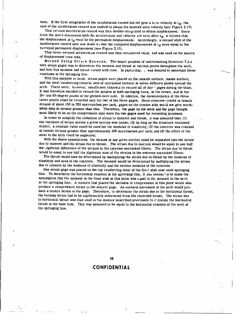
Method Using Strain Records. The major purpose of instrumentingStructure 3 .1.nwith strain gages was to determine the moment and thrust at various points throughout the arch,and how this moment and t.hrubt %aried with time. In particular, - was desired to ascertain these ..reactions at the springing line.
Wi.th this purpose in m~nd, strain gages were placed on the outside surface, Inside surface,and the steel reinforcing (neutral axis of uncracked section) at seven different points around thearch. There were, hosever, insufficient channeis to record all of they , gages during the blast.It was therefore decided to record the strains at both springing lines, at the crown, auid at the30- and 60-degree points of the ground-zero side. In addition, the measurements at the threelatter points could be recorded only for twc of the three gages. Since concrete cracks at tensilestrains of about 100 to 200 microinches per inch, gages on the tension side woid not give worth-while data at strains greater than this. Therefore, the gage on the steel and the gage thoughtmost likely to be on the compression side were the two gages used for recording purposes.
In order to simplify the reduction of strain to moment and thrust, it was assumed that: (1)the variation of strain across a given section was linear; (2) as long as the structure remainedelastic, a constant value could be used for the modulus of elasticity; (3) the concrete was crackedat tensile strains greater that approximately 100 microinches per inch; and (4) the effect of thesteel in the arch ,ould be neglected.
With the above assumptions, the strains at any given section could be separated into the straindue to moment and the strain due to thrust. The strain due to moLent would be equal to one halfthe ,dgebraic difference of the strains in the extreme uncracked fibers. The strain die to thrustwould be equal to one half the algebraic sum of the strains in the extreme uncracked fibers.
The thrust would then be determined by multiplying the strain due to thrust by the modulus ofelasticity and area of the concrete. The moment would be determined by multiplying the straindue to moment by the modulus of elasticity and the section modulus of the concrete.
One strain gage was placed on the top reinforcing steel of the flo,,r slab near each springingline. To determine the horizontal reaction at the sproging line, it was neceso-t-y to make theassumption that the moment in the floor slab at this point was e.ual to tht moment in the archat the springing line. A moment that placed the intrados in compression at this point would alsoproduce a compressive strain in the subject gage. An outward movement of the arch would pro-duce a tensile strain in the gage. Therefore, to determine the strain due to the horizontal thrust,the bending strain had to be algebraically subtracted from the recorded strain. The strain dueto horizontal thrust was then used in the manner described previously to c°Jculate the horizontalthrust in the base slab. This was assumed to be equal to the horizontal reaction of the arch atthe springing line.
39
CONFIDENTIAL

C.4op/er 3
RESLL TS
All four of the structures withstood the effects of the Priscilla Fhot and remained In usable con-lition. Even though none of the 3.1 structures failed, valuable informat.on was obtained fromhe test. The buried concrete arches proved very effective in resisting the blast effects from
a nuclear weapon.This chapter p-esents only the peak vlutns of transient and permanent measurements. The
variations of earth prssure, deflection, acceleration, etc., with time are presented in AppendicesB and C.
3.1 AIR OVERPRESSURE
The actual air overoressures receivea at the three ranges were 56, 124, and 199 psi com-pared to the predicted values of 50, 100, and 200 psi. The project plot plan (Figure 2.1) showsthat Structures 3.1.a and 3.1.n received the lowest loading of 56 psi, Structure 3.1.b next with 124psi, and Structure 3.1.c received 199 psi, the highest loading. The closeness of the predictedvalues to the recorded values indicated that toad-input conditions in this test were satisfactory.
The ground-surface air-overpressure values measured by the self-recording pressure gagesappear reliable, since these values compare favorably with the blast-line data. The blast linewas located approximately 250 feet from the above gages.
Measurements showed no increase in air pressure within any of tie four structures duringthe test.
3.2 EARTH PRESSURE
The peak transient earth pressures on Structure 3.1.b (see Figure 3.1) show that in severalinstances the earth pressure exceeded the ground-surface air ovrvressure. Even though thevalues of pressure were recorded to the nearest one psi, some of the values could not be ac-curately determined because either the range of the calibration or the range of the amplifyingequipment was exceeded rhls was especially true for gages ElO and El0.1, at the crown ofStructure 3.1.b. These gages were placed next to each other in order to determine what effectthe method of mounting had on earth-pressure measurements (see Appendix B). Only the peakearth-pressure values for the precursor phase could be compared sincp the peak values for themain shock phase were beyond the calibrated range of the gages.
A comparison of pressLre values from gages E9 and Eli shows that the Ivading was asym-metrical. The peak pressure for gage ED, located on the ground-zero side, was 60 percenthigher than for gage Ell, located on the lee side of the arch.
It should be pointed out that the earth pressures being dscusse," are transient pressures re-sulting from ground-surface air overpressure and that the static earth pressures (dead load)existing at the time of the shot are not included. Negative values would indicate reductions inthe existing static errth pressures.
The geometry of the earth-pressure gage mounting at the 30- and 60-degree positions on Struc-ture 3.1.n (see Figure C.A) adversely affected the measarements. The projection of the mountsinto the soil apparently caused ar increase of pressure on the gages measuring vertical pressuresand, possibly because of arching, a decrease on the gages measuring horizontal pressure. The
40
CONFIDENTIAL

KEY PLAN
I I .. .
26 SI psi04us T, .- 74 Wf:
3? Psi AT 41 he
0 031 At 417 WS
37AWUc.ruIE :3 tA,( N
EIO
AT 270 uss SaEIOJ PCAA OvfvRLSSUpr
P. S24 PSI i
AT 2*2
AT' 248 MeIS? PSI f.
ol ~ PEAK OVCIOWPIJC 3 /P,, P isP
E A T 23 M& o ACORDT,4 M.)S
W 1 No RECORD£1NO RECORD EI
145 P'I
AT 236 MS 5 3TRUCTUr 3.I.C
E-EARTH PRESSURE GAGE
NOTE ZERO TIME IS TAKIEN AS THE TIME OF OETONATION OF THE oDViCE
Figure 3.1 Peak transient earth promare, Structures 3.1.a , c, and n.
41
CONFDENTIAL

KEYr PLAN
-0130-LAT434,u all0 I4 tN AT 424 MS
STRUCTURE 3.1.A
of*z
0 T126 ms
347 IN. AT
STRUCTURE 3 .1.
AT 242V
STRUCTURE 3.I.C
0-ELECTRONIC DEFLECTION GAGE
NOTE ZERO TIME IS TAK~EN AS THE TIME OF DETONATION OF THE DEVICE
Figure 3.2 Peak transient deflection, with respect to the center ofthe floor slab, Structures 3. 1.a, b, and c.
42
CONFIDENTIAL

-~ 'G2.
KEY PLAN
Gz
3TRUCTURE 3.1.A
AT 345 U
0 50 OIN
A 3 1-O ? AT 255 us
STRUCTURE 3.1.C
0-ELCTRNCDEFECTON AGE
NOT ZROTIE S AIENASTH TMEOFDEONTIN F !EDE2C
igre 2?M 3. ektasetdelcinwt epett pignline Strcturs 31.ab, adoc
IN3-0 3 I COAN35$ 31E-I C4AT 1 A
gages at the crown and springing line, however, were flush-mounted and gave what appear to bereliable measurements, which are included in Figure 3.1.
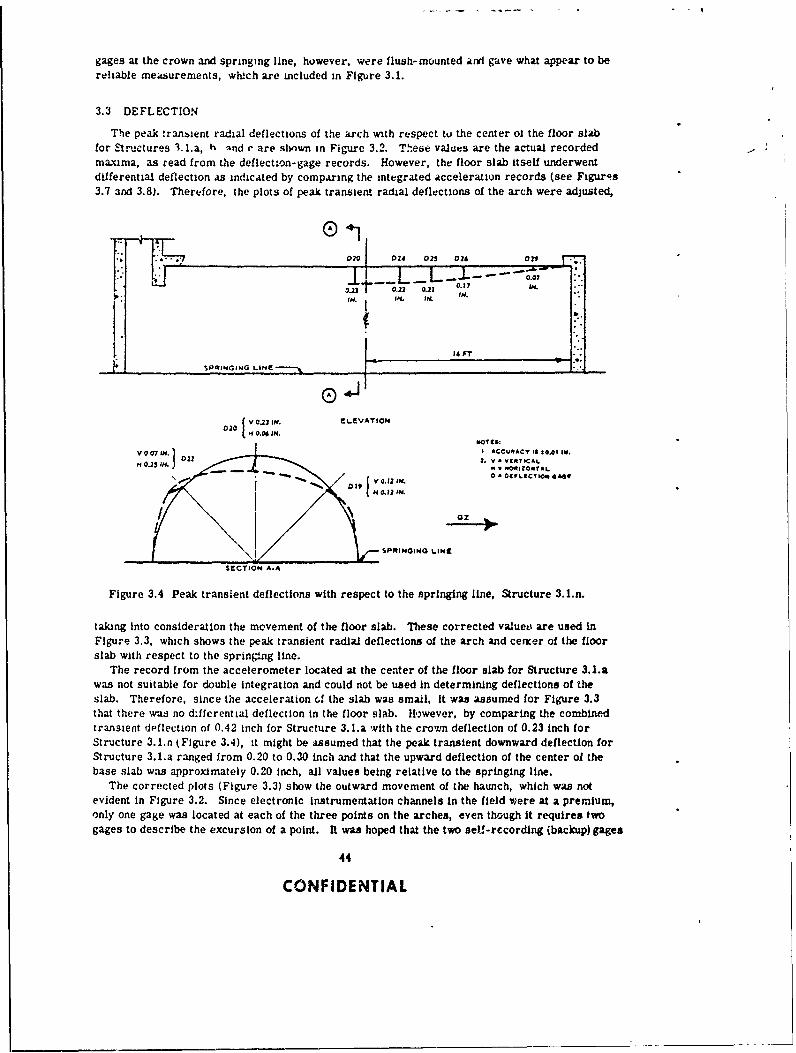
3.3 DEFLECTION
The peak ,ran!ient radial deflections of the arch with respect tu the center o1 the floor slabfor Structures 3. l.a, h nnd e are shown in Figure 3.2. These values are the actual recordedmaxima, as read from the deflection-gage records. However, the floor slab itself underwentdifferential deflection as indicated by comparing the integrated acceleration records (see Figuros3.7 and 3.8). Therefore, the plots of peak transient radial deflections of the arch were adjusted,
O*1
0 ELEVATION
02 *. v.•VIICTAL.H 0.2S . N • "OIO*TAL.
SPSINGIN IINE
$EVCTION AIA
Figure 3.4 Peak transient deflections with respect to the springing line, Structure 3.l.n.
taking into consideration the movement of the floor slab. These corrected valuet' are used inFigure 3.3. which shows the peak transient radial deflections of the arch and cesger of the floorslab with respect to the sprinAng line.
The record from the accelerometer located at the center of the floor slab for Structure 3.1.awas not suitable for double integration and could not be used in determining deflections of theslab. Therefore, since the acceleration ci the slab was small, it was assumed for Figure 3.3that there was no d~ffcrential deflection in the floor slab. Hwever, by comparing the combinedtransient deflection of 0.42 Inch for Structure 3.l.a with the crown deflection of 0.23 inch forStructure 3.1.n tFigure 3.4), it might be assumed that the peak transient downward deflection forStructure 3.1.a ranged from 0.20 to 0.30 inch and that the upward deflection of the center of thebase slab was approximately 0.20 inch, all values being relative to the springing line.
The corrected plots (Figure 3.3) show the outward movement of the haunch, which was notevident in Figure 3.2. Since electronic instrumentation channels in the field were at a premium,only one gage was located at each of the three points on the arches, even though it requires twogages to describe the excursion of a point. It was hoped that the two self-recording ibackup) gages
44
CONFIDENTIAL

would describe both the horizontal and vertical movement of the crown; however, none of the self-recording deflection gages functioned.
The peak transient deflections of the 3.l.n arch with respect to the springing lines are shownin Figure 3.4. In this structure two gages were used at each point to trace both the horizontaland vertical movements. Scct!on A-A of Figure 3.4 shows the maximum excursion of three pointson the intrados near t: 4 center of the structure. These deflections show that the structure under-went bending with tne crown moving downward and the haunches outward. I can also be observedthat the bending was slightly asymmetrical with some movement away from ground zero. Theelevation view shows the deflections of the crown along the longitudinal center line of the arch.Th, def ections of this structvre were not large enough to definitely establish the ditance towhich the end wals affected a.-ch action. Tnis wi imucated, however, !Zy p ern of thecracks discussed in Section 3.8.
The permanent deflection of the crown with respect to the springing line for Structure 3.1.a,b, and c is compared in Figure 3.5, again showing the influence of the end walls in restraining
A~~~~ SSibIG I~
-.- 1.4
Figure 3.5 Permanent crown deflection with respect to the springing lineof the arch. Structures 3.1.a, 3.1.b, and 3.1.c.
arch deflection. The permanent deflection of the crown with respect to the springing line forStructure 3.1.n measured less than 0.05 inch. The permanent deflections determined from alevel survey are given in Tables 3.1, 3.2, 3.3, and 3.4.
3.4 ACCELERATION
The peak transient accelerations of the floor slabs are shown in Figure 3.6. The largestacceleration was a 13.4 g at the springing line of Structure 3.lI.c. This acceleration had aduration of approximately 25 milliseconds. It is interesting to compare this peak floor-slabacceleration of 13.4 g with the peak free-field acceleration of the soil. The top of the floors.1ab was 12Y% feet below the ground surface. At a depth of 10 feet and at the same range asStructure 3.1.c, References 12 and 19 show free-field accelerations of 16.5 g and 17.1 g,respectively, It is also interesting to observe how the acceleration increases as the overpres-sure increases. The same references indicate that by increasing the ground-surface air over-pressure from 200 to 300 psi the peak acceleration at a depth of 10 feet would be increased from
45
'CON FPDENT IA L
o,
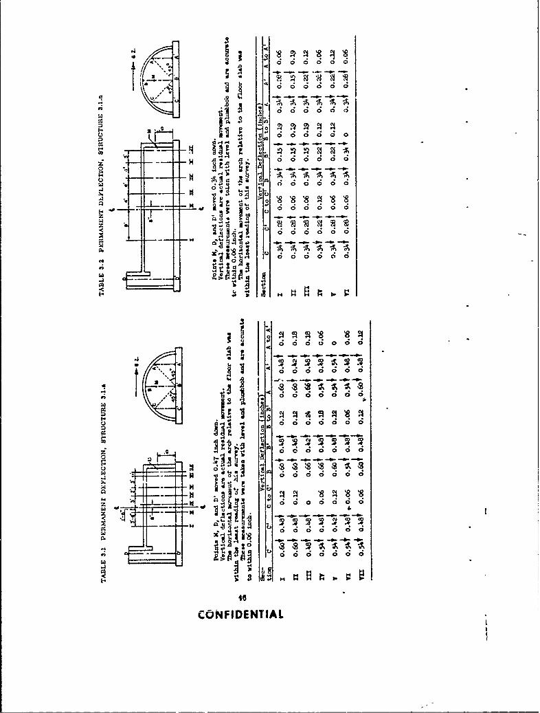
a ~ ~ ~ . 0 --- ---.-
o' 0 0 0 0
- A pQ0 S~ - f 0.0 0 0 0r 000 00
ff4
ru=~- - -,~ , -I a
01i 0000
f 40 1
16.-. - . - 4-
4 44
CONFIENTIA

. .! . . . U4
-~~~~ -0-~- - .
-9 o
H.. 14 C. H r
fl 5 - r'J M
dddAAARA
o~~~ o-.---.*
.- O i:. 00
41--~- ~ 4
0 0 0 000 0
00S. -*, -- 0- -.--
A ;
00
ooocidIs In
t . 0 0 0 0 0 0 0
00
V3 0 3 . . 4 4
-3 8~ -i 8 8 A
43t
'-C3
z ~ ~ ~ ~ ~ ~ ~ ~ ~ V r4c ic .4. ic ic~ ~ 1* ** -~ ~ - - -.- b. 47
COFIENIA
G z
KEY PLAN
AA4G MS AAS N a u
17S AT 410 US , 0& AT 413 MS
STRUCTURE 3.I.A
GZ
4 ?S AT 330 US AT 4331
A4 A3_
-S.2~ A 87 MSI -o G rA?2 M
STRUCTURE 3.1.8
oz
1 0 6 g AT 22? US-134 1 AT 217 MS
STRUCTURE 3.1 C
A - ACCtLEROMETER
NOTE ZERO TIME IS TAKEN AS THE TIME OF DETONATION OF THE DEVICE
Figure 3.6 Peak transient zcceleration, Structure. 3.1.a, b, ad c.
48
CONFIDENTIAL

an average of 16.8 g to an average of about 150 g. These high values of acceleration wouldmost probably be physiologically hazardous to personnel (Reference 31).
The adjusted double-integrated acceleratiun records (see Section 2.3.3 for the method usedin "ategrating records) for gages A-3 and A-4 of Str,,cture 3.1.b, and IAV-10 of Reference 12are shown in Figures 3.7, 3.8, and 3.9, respectively. Th,. dt:flection history of the base slaband free-field measurements as shown in the three figures was used in the preparation of atransient history of earth pressure and deflection for Structure 3.1.b shown in Figure 4.2 of thenext chapter. Figures 3.7 and 3.8 were also used in preparing Figure 3.3. The adjusted recordsfor Structures 3.1.a and c are not shown.
3.5 STRAIN
Strain-versus-time records were taken at 16 points on Structure 3.1.n. Peak transient valuesof strain approximately 15C milliseconds after the arrival of the blast wave at the structure areshown in Figure 3.10. The three strains at the springing line on the ground-zero side plot intoessentially a straight line for any given time. At all other gage sections only two strain valueswere recorded. A straight line was drawn through eac4 set of values. Strains were not recordedon tny of the other test structures.
It was assumed that the concrete cracked at tensile strains greater than about 100 microinchesper inch. Based on this assumption, it is believed that the concrete was cracked to a depth ofgreater than 3 inches in some places.
The largest recordea concrete strain was 575 microinches per inch, at the crown on the ex-trados. A concrete modulus of elasticity of 4.5 x 10' psi would give a resulting stress of about2,600 psi. The largest recorded steel strain was 1,000 microinches per inch in tension. It wasin the top steel in the center of the floor slab. When multiplied by a steel modulus of elasticityof 30 X 101 psi, t' ! resulting steel stress was 30,000 psi in tension.
The values of residual or permanent concrete strains were low, as can be seen in Figure 3.11.Large tensile strains indicate cracks, as can be seen by comparing with Figure 3.17.
3.6 MISSILES
No missiles (concrete fragments) were found in the missile traps in any of the structures.
3.7 RADIATION
A summary of the total radiation dose within the four structures and the total amount at theground surface (free-field radiation dose) is shown in Figures 3.12 through 3.15. These fourfigures show that the entranceways admitted the major portion of the radiation dose into thestructures. Although no special effort was made to attenuate radiation at the entranceways,examination of the figures shows that radiation was attenuated greatly with distance.
3.8 DAMAGE SURVEY
Structure 3.1.a. Visual inspection of the interior of this structure Indicated minor damagein the form of small hairline cracks located mainly in the floor slab. The location of thesecracks is shown in Figure 3.16.
Structure 3.1.n. Visual inspection of the interior of this structure indicated minor damagein the for-, of small hairline cracks located in the floor and Intrados. The location and size ofthe cracks are shown in Figure 3.17. The restraint of the end walls on the arch action is graph-ically illu,trated by these cracks, even though the cracks are of insignificant widths. The crackpattern indicates that the end walls affected the arch for a distance of about 11 feet, or slightlyless than 1 /2 times the arch radius.
Structure 3.l.b. Visual inspection indicated minor damage in the form of small- to medlu.size cracka. The width of cracks in the floor slab varied from hairline to iss inch; the crackr
49 (Text continued on Page 59)
CONFIDENTIAL

MAremWJ3
It is d'o J0 a 0 f " -
oi
I T f
SVI
.--. 1 -AP
at ,, W -
__ I _I- - - -
Figure 3.0 Adjuated doule-ntegraton o Record A-3, Stuct e 3.1.b.
50
CONFIDENTIAL
V - ----~- -A No b o W4 "0 903. Jo 10 ,*0 o J#2 O J"
---. I- I J..& w I.f
4m .0
Figure 3.8 Adjusted double- integration of Record A-4, Stucture 3.1.b.
CONFIDENTIAL
-in
Ii T I I
i I
I ' ! I
j j ---iii-Iif,, =w r,a li -:.m~' . - -!,w
Figure 3.9 4Justed doiable- integration of Reord IAV-10 (free-field), Reference 12.
52
CONFIDENTIAL
__ I -il~ _
0Io 0
o C.
00
.Lo40 0 0 0 0 0O 0
-o C'00-C'
0000.000000000000 c 0
U r S
0 Li
IL 0
.4'
0 4* w
0 % V)
ccz
2 ~ 00Id a u
in U5MCONFIDENTIAL
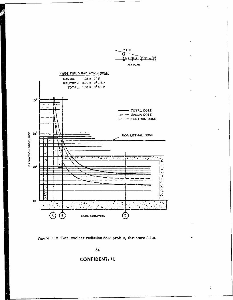
pN
I(EY PLAN
FREE FIELD RADIATION DOSE
GAMMA: 1.05 x 10⁵ R
NEUTRON: 0.75 x 10 REP
TOTAL: 1.80 x 10 5 REP
-- TOTAL DOSE
--- GAMMA DOSENEUTRON DOSE
-- 100% LETHAL DOSE
z0Va
o 0 . .......4
10NFIDEN _ _ __L
Figure 3.12 Total nuclear radiation dose profile, Structure 3.1.a.
54
CONFIDENTi IL
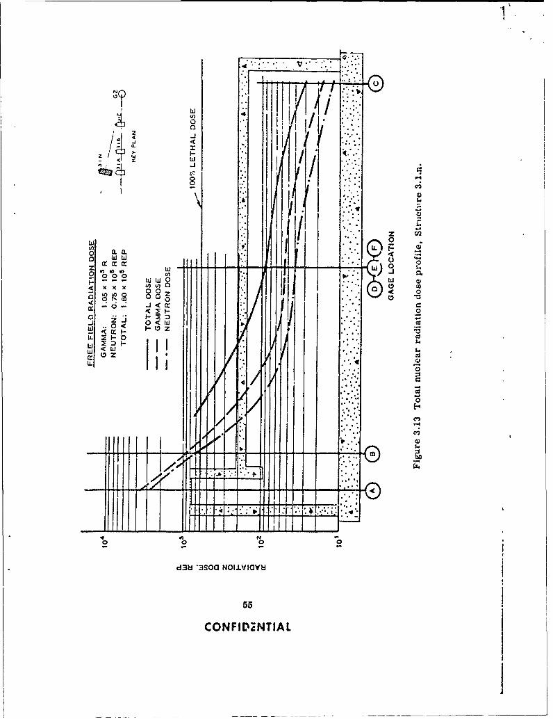
NTI
CL.
004
x iii 1rW'a to koi b o
x x w..0i .
m0 -z
LLi
100 c0
d38Z '3I~ .O~a
55i
U. NFINNTJA0
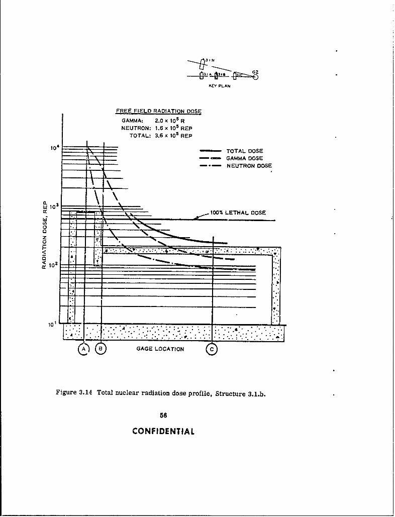
KEY PLAN
FREE FIELD RADIATION DOSE
GAMMA: 2.0 x 10⁵ RNEUTRON: 1.6 x 10⁵ REP
TOTAL: 3.6 x 10⁵ REP
104 TOTAL DOSEtiff_ GAMMA DOSE
NEUTRON DOSE
.100% LETHAL DOSE
0
z
<02
10 1 .
GAGE LOCATIONC
Figure 3.14 Total nuclear radiation dose profile, Structure 3.1.b.
56
CONFIDENTIAL

KEY P.AN
FREE FIELD RADIATION DOSE
GAMMA: 3.0 x 10 R
NEUTRON: 2.5 x 10⁵ REPTOTAL: 5.5 x 10 5 REP
TOTAL DOSE
10' - GAMMA DOSE__ _ -iI NEUTRON DOSE
100% LETHAL DOSE
0. 103 __ __
It\-
a "0
0I__ _ _ _ __ _ _ _ _ _ I I I _ _ _ _ _ _ I
(02
10 11
Figure 3.15 Total nuclear radiation dose profile, Structure 3.1.c.
57
CONrIDENTIAL
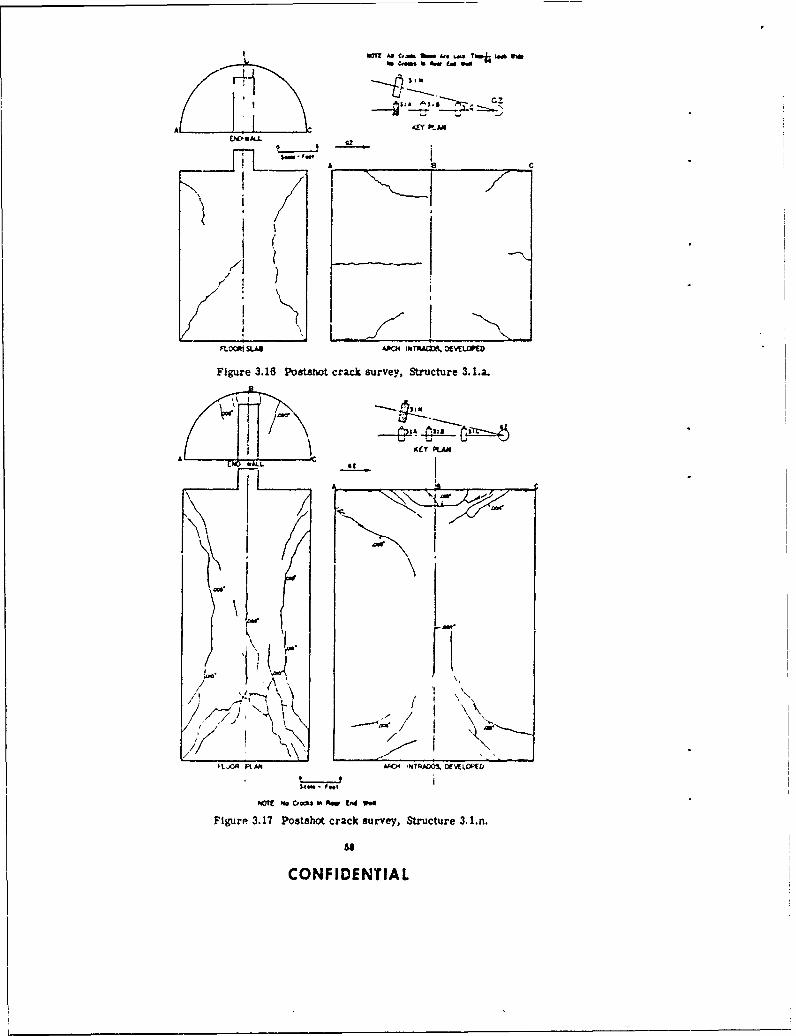
my? "l C.- t 4 Th1j.i Wfb fow I" son
A gA S.
KEY PLA
A c
r77
FLO* SAA "CilRA", ocwuww
Figure 3.18 Postsot crack survey, Structure 3.1.a.
Key PLAN
'I,, /'
I ?o L
Ft," O I RAM A" NiTiAD0. 0(WL0K&
M o- FNI
PETE No osI m Co W"e
Figure 3.17 Postshot crack survey, Structure 3.1.n.
CONFIDENTIAL
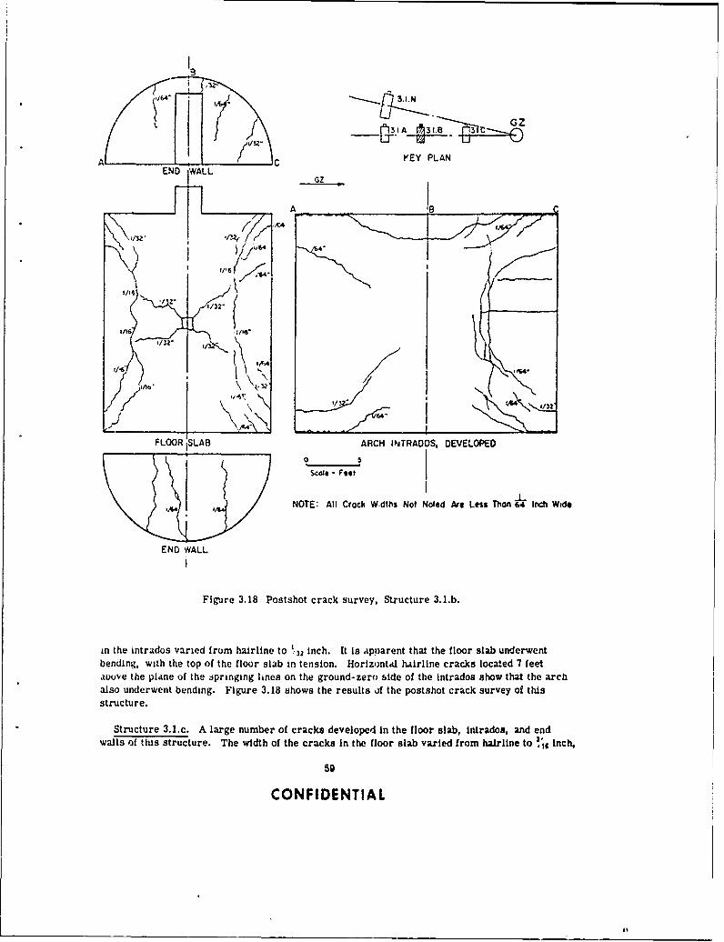
9
I6
-A. C YEY PLANEND WALL
GZ
A _ _ _ _ _ _ _ _ _ _ _ _ _ _ _ _(__ _ _ _ _ _
A.I
'I. I1132
FLOOR 1SLAB ARCH IN~TRADOS, DEVELOPED
NOTE: All Crack W.dths Not Noted Are Less Than " lr Ich Wid*
END WALL
Figure 3.18 Postshot crack survey, Structure 3.1.b.
in the intrados varied from hairline to 1,32 inch. It Is ,apparent that the floor slab underwentbending, with the top of the floor slab in tension. Horizontal hairline cracks located 7 feetavuve the plane of the zpringing lines on the ground-zero side of the intrados show that the archalso underwent bending. Figure 3.18 shows the results of the postshot crack survey of this
structure.
Structure 3.1.c. A large number of cracks developed In the floor slab, Intrados, and endwalls of this structure. The width of the cracks In the floor slab varied from hairline to ,'Ig Inch,
59
CONFIDENTIAL
49
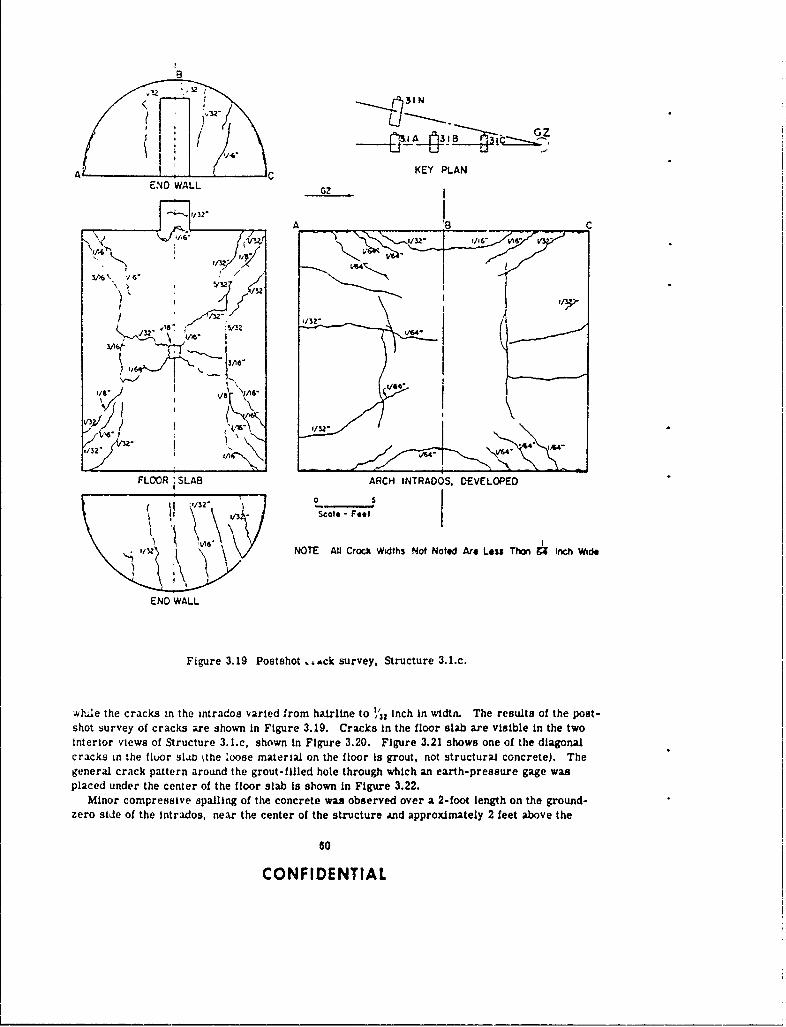
8
A..
END WALL
A C
3A6~ //
132_ _v ' / " 3 2 (/2 /6
11 0, -
FLOOR SLAB ARCH INTRADOS, DEVELOPED
lAO V NOTE All Crocki Widths Not Noted Are Lass1 Tt Inch Wiel
"V"
END WALL
Figure 3.19 Postshot ,Lc survey, Structure 3.1.c.
wle the cra cks in the intrados varied from hairbline to 1 inch in widt. The results of the post-
shot survey of cracks are shown in Figure 3.19. Cracks in the floor slab are visible in the two
interior views of Structure 3.l.c, shown in Figure 3.20. Figure 3.21 shows one of the diagonal,
cracks in the floor slib tthe loose materld on the floor Is grout, not structural concrete). The
general crack pattern around the grout-filled hole through which an earth-pressure gage was
placed under the center of the floor slab is shown in Figure 3.22.
Minor compressive apallIng of the concrete was observed over a 2-foot length on the ground-
zero siJe of the Intrados, near the center of the structure jnd approximately 2 feet above the
0
CONFIDENTIAL

14-
4IX,.. A'
~ 5.VV
'044
eq
t cn
4,4
______mum
,*1
CONIDETIA
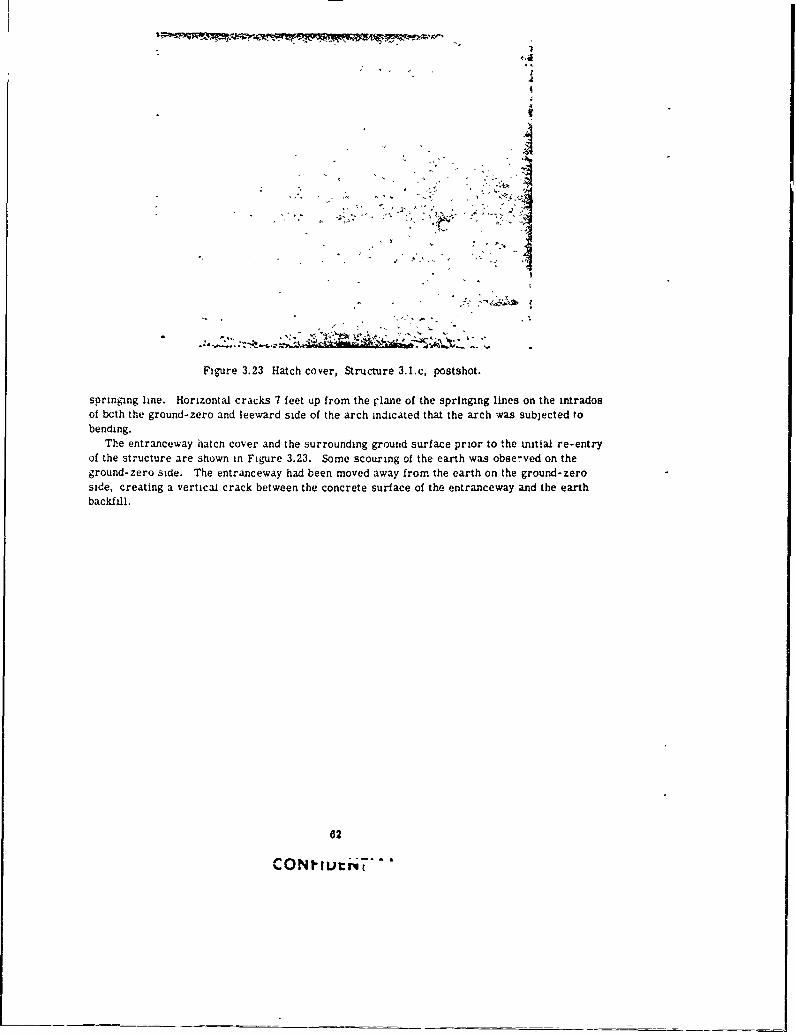
.4TII
AN
01~~ ....
Figure 3.23 Hatch cover, Structure 3.1.c, postshot.
springing line. Horizontal cracks 7 feet up from the plane of the springing lines on the intradosof bcth the ground-zero and leeward side of the arch indicated that the arch was subjected tobending.
The entranceway hatcn cover and the surrounding ground surface prior to the initial re-entryof the structure are shown in Figure 3.23. Some scouring of the earth was observed on theground-zero side. The entranceway had been moved away from the earth on the ground-zeroside, creating a vertical crack between the concrete surface of the entranceway and the earthbackfill.
62
CON? ."

Chop/er 4
DISCUSSION of RESULTS
4.1 CONSTRUCTION MATERIALS
In a field test in which the load is generated by an atomic veapon, it is just as important thatthe actual strength of the materials involved (i. e., the concre.e, reinforcing steel, and soil)closely approximate their design strength values as it is for the actual blast pressure to closelyapproximate the design blast pressure. The degree of proximity of the actual values of materialstrength and blast pressure to the predicted values dictates the degree of success of the experi-
ment.
4.1.1 Concrete Strength. The average concrete compressive strength of the four structures
at the time of the Priscilla Shot was approximately 4,500 psi, o.- 59 percent greater than thedesign strength of 3,000 psi. Therefore, the structural capacity of the arch structures to resistoverpressure loadings was accordingly greater. The average concrete strength for Structure3.1.c (199-psi air-overpr'ssure level) at shot time was 4,300 psi, i-Lch was 60 percent greaterthan the design strejigt. If it is assumed that resistance to failure depends on ultimate con-
crete strength, then the ultimate load (ground-surface overpressure that would cause collapse)for the 4,800-psi concrete would be appreciably greater than that for the 3,000-psi concrete.
If a urform radial loading (Figure A.1, Loading A) is used and 3,000-psi and 4.800-psi con-
crete strengths are assumed, the calculated collapsing air overpressures for Structure 3.1.cfor these two strengths would be 280 psi and 450 psi, respectively.
4.1.2 Backfill Material. In tests of buried structures, knowledge of backfill material isimportant since it is through this medium that the air-induced ground shock must pass in order
to act upon the structures.The degree to which the load is diverted from twe structure (the arching action of soil) Is a
difflcult quantity to evaluate and no attempt is made in this report to determine the archingcharacteristics of the soil surrounding the test structures. However, the backfil was placedand controlled so that the modulus of compressibility would be the same as that of the adjacentnatural soil; tmus, a gien ovcrpressure .vouia cause equal deflections in the backfill and in thenatural soil. (See Table 2.2 for a comparison of moduli of compressibility. ) In order to attainthis duplication of the modull of compressib'hity, It was necessary that the density and the water
content of the backfill material be greater than that of the natural soil. Because of the duplica-tion of the compressive moduli, the test structures were surrounded by soil having nearly the
same load-carrying capacity as that of the natural soil.By comparing the density and water-content samples prior to and after the shot, it was
found that no change in water content or density of the backfilled soil occurred at depths of 4feet below the ground surface at the three pressure levels.
The depth oi the backfill over the arches was not changed by the effects of the chot. The
measured depth of earth cover over the crown of Structures 3.1.a, b, c, and n was 4.3, 4.1,4.1, and 4.2 feet, respectively.
The strains and deflections measured on Structure 3.l.n during backfilling were small. Ap-proximately 250 strain readings were taken, none of which were greater than 50 microinchesper inch. The deflection i eadlngs showed that during backfilling the maximum upward deflectionof the crown was about 0.01 inch and the maximum inward deflection of the haunch midway be-
83
CONFIDENTIAL
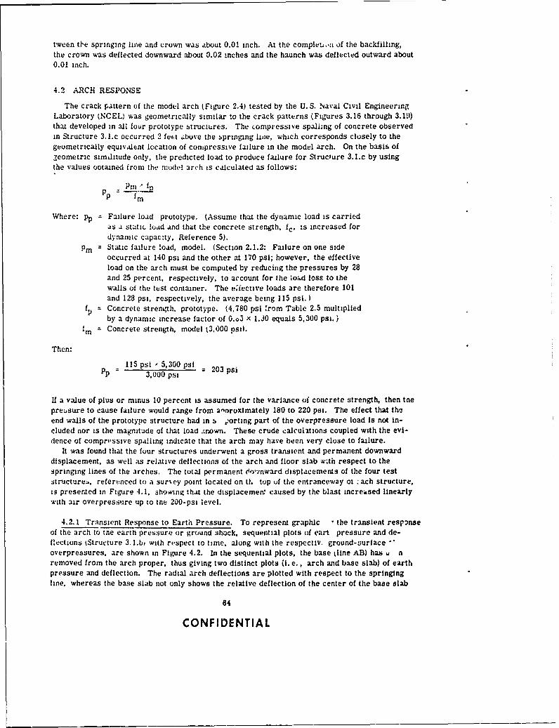
tween the springing line and crown was about 0.0! inch. At the completi.a of the backilling,the crown was deflected downward about 0.02 ,aches and the haunch was deflected outward about0.01 inch.
4.2 ARCH RESPONSE
The crack pattern of the model arch (Figure 2.4) tested by the U.S. Naval Civil EngineeringLaboratory INCEL) was geometrically similar to the crack patterns (Figures 3.16 through 3.111)that developed in all four prototype structures. The ,ompressive spalhing of concrete observedin Structure 3.l.c occurred 2 feet ;,buve the springing line, which corresponds closely to thegeometrically equivalent location of compressive failure in the model arch. On the basis ofleometric simditude only, the predicted load to produce failure for Structure 3.1.c by usingthe values ootained from the :model arch is calculated as follows:
Pm Jp = --- m
Where: pp = Failure load prototype. (Assume that the dynamic load is carriedas a sttic load and that the concrete strength, fc, is increased fordynanic capacity, Reference 5).
Pin= Static failure load, model. (Section 2.1.2: Failure on one sideoccurred at 140 psi and the other at 170 psi; however, the effectiveload on the arch must be computed by reducing the pressures by 28and 25 percent. respectively, to account for the lo;ad loss to thewalls of the test container. The eiective loads are therefore 101and 128 psi, respectively, the average being 115 psi. )
fp = Concrete strength, prototype. (4,780 psi ,rom Table 2.5 multipliedby a dynamic increase factor of 0.o3 x 1.30 equals 5,300 psi.)
fin = Concrete strength, model t3,000 psi).
Then:
115 psi 5,300 psi = 203 psiPP = 3,000 psi
If a value of plus or minus 10 percent is assumed for the variance of concrete strength, then toepreLsure to cause failure would range from annroximately 180 to 220 psi. The effect that theend walls of the prototype structure had in s , orting part of the overpressure load is not in-cluded nor is the magnitude of that load .tnown. These crude calculitions coupled with the evi-dence of compressive spalling indicate that the arch may have been very close to failure.
It was found that the four structures underwent a gross transient and permanent downwarddisplacement, as well as relative deflections of the arch and floor slab wth respect to thespringing lines of the arches. The total permanent do'rnward displacements of the four teststructures,, referenced to a sur%ey point located on tt. top of the entranceway ot .ach structure,is presented in Figure 4.1, showing that the displacemen caused by the blast increased linearlywith air overpressure up to tne 200-psi level.
4.2.1 Transient Response to Earth Pressure. To represent graphic • the transient responseof the arch to tne earth pressure or ground shock, sequential plots of eart pressure and de-flections iStructure 3. l.b) with respect to time, along with the respectiv, ground-surface -"overpressures, are shown in Figure 4.2. In the sequential plots, the base kline AB) has u nremoved from the arch proper, thus giving two distinct plots (i. e., arch and base slab) of earthpressure and deflection. The radial arch deflections are plotted with respect to the springingline, whereas the base slab not only shows the relative deflection of the center of the base slab
64
CONFIDENTIAL
with respect to the sprl-nging line but also shows the transient gross displacement of the spring-ing line as well. In addition, based on data obtained in Project 1.5, (Reference 12), free-fieldsoil displacement determined at the same air-overpressure range (see Figure 3.9) also is shownLn F:gure 4.2. Even though the free-field data were taken at a depth of 10 feet and the top of the
ISTUCF R- 3.1.c -
:'° t __ __ I ___- . !ji, IIiI~jz
.1,IIaI I N iii i
- -I-- ' 00STRUCTURCJ.1.n --
lEV ! I . I t;
I 4OT1L OIWLAC.MEP.T1WAS NCYKAMC90 TO AWASVEY 01IMI LOCATCO 04 TM6 TOP OF
___ 1 TME rM.TRANCOMAY OF CAC. STXUCTUNaT I In
0 20 40 4 44 III 1z 1 g Is Z0 220"AK OV9KNPWKMUR. PI
Figure 4.1 Permanent downward displacement of the 3.1 structures.
slab of the tst structure described herein was located 12 feet 8 inches below the ground surface,the free-field data were re!erenced to the original location of the baiae slab (line A0 Bo) so that adirect comparison of displacement could be made.
The air-induced ground shock arrived approximately 200 msec afier zero time (time of det-onation). The first visible effects of earth prcssure on the crown of the arch occurred at 205msec. The fol.owing is a description of the response of the arch structure at the times of thevarious plots shown in Figure 4.2.
At 2 10 m sec: The entire structure began moving downward (gross movement) as a rigidbody; the free-lield point had not yet started to move.
At 230 msec: The earth pressure was nearly uniform over the entire arch surface andbase slab. The free-fleid ")oint noved downward 0.14 inches while the base slab moved down-ward 0.11 inches.
A t 250 ms e c: The precursor wave was nearly terminated and the decrease in earth pres-sure could be obsei ved. In addif"on to the gross displacement of the structure as a whole, thearch began to deflect with respect to the springing line.
At 260 ms ec: The main shock arrived. Here again, the crown, by virtue of Its position,was subjected to load before the free-field point, which explains why the downward movementof the base slab caught tip with the downward displacement of the free-Hield point. Apparentlythe arch deflection had not yet responded to the main shock. It was also observed that the pres-sure at the 45-degree lines increased slightly, while the pressure at the springing line was es-sentially zero. This fact was also obseried during the initial precursor build-up at 210 msec.
At 270 m aec : The earth pressure was rapidly building up ai ound the arch with thegreatest pressure at th? crown. The pressure on the base slab at the center was decreasing,
65 (Text continued on Pag. 74)
CONFIDENTIAL
O9 0
N --,- 2 -
0 w4 ..J( ..D
0 0
N1 N [. T
I~IL27I 0 w-
.0 0do
l - -0S4d N1 zoo
0'41
01100 09
I I
900
N I
o 0!
z -"
,,0, o 0 ,.0 2 , 00 1
D~sn ol"o \1 j bo0 0 ~0
NIIOI I 2
o .re , .c.. .
2 o o f
ld • s.
N~~ ~ 00lN
00
C N II-
8
CONFIDE NTIAL
00 U
N0-1
52
2 co w-o w
J2 4.0o- I ~. z
A b
-CD 1. . 400
0 0 0
'o 0
'HII0 0
000
0 00C
0,,
0 do d
z ,I
C) A1 A0
0
00.
CONFIENTaA

0 U0-
0
Z 2
CL 9 '
2 ~
z -A
01 s.0
of.
-N 0 0J 0-u I2. - 1 0~I
J(0.E Isd NJ CVQo
N ~I~NJ
,' 0
iL
cc 0 0 j 11
00 0
t 00'I0-I
1 -n
-z 2
0 0-7 S .9'1 -i % I--1
NO 4., (c IU, 0
00
0S 0
Isd -S4~A\aN C0C 0
0 0
000
8
CONFIDENTIAL
>zC2
o>0
z 0~
21 x I .
<1 0-a
' > 1 1 0
2 1- I U -I |- -',-,o
- 4t I
-'3 - W1 -
1I 0
NII _ _ _
o0 00 0
ITI
I, 000
-
0E
225
~3cr oe0OQ<0 Z
0~ -
I. 0
N0 0 1
0
00
o o
000
CONFIDENTIAL

0
I - z
00
uIL a1 0
01 0 0.
00
010N1. 40 --
-o-4£0
I ~ ~ ~ I dWl~~ N1__ _ 9z a
0 174
o 0
D3S"0 oz
D~ 28
COFDETA
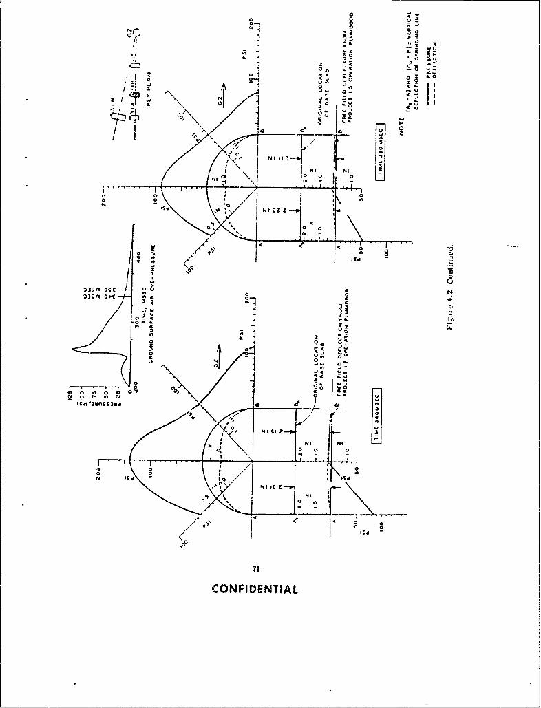
0
011 >
1 ZZ
0 IL 0024 C
0
i 2,1 P4
N- 0--l 0IN I hl
0~ 0 u .0 i
04 0
00
IL 0
SIMI 0s:)3Sn.~ 4S 00
& 2 0
00q~
A~ a 4isti 'vncsiv
0, N SI z -- ,V
NJ a .J NJ L
71,
N V4 to~
NN INICZ--1
0 a 0
71
CONFIDENTIAL
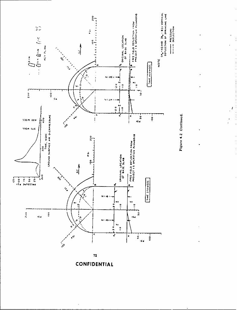
L el
0
0000
00e4
01 -
0. II I'A 2 0
z -~ I
0 u -.Fi0 '
0 00 0 0 a
1 Is I-
0 30
N1-
- ~ 4 0
~3Cn 0~ j72
CONFIENTIA
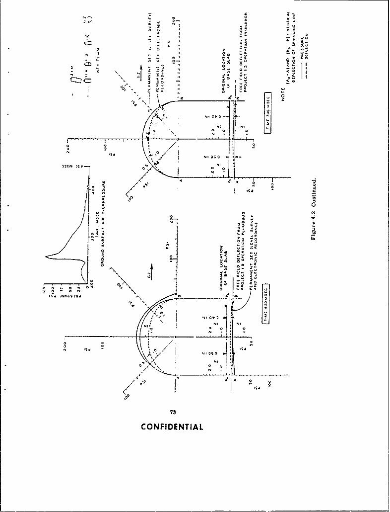
o . 0 2= '' o
0-0
o o-
~~I 0
-, '- - " -
I?" " ' ',/ O/.
0 0 1 0
.. . .. . .- . . ," - ti'-!:L aI I
~3~~rI
000
0 007 C'.r 00
0~ 0
L. .12
0 0-
' ' I 0 .iZ
uI 0 0
01, z0 4,
0 0, ct
9 0 0' NI
0 0
" I[d -
0 0/ .*4 0 'w
I j 0
9s
0C0
73
CONFIDENTIAL

,while the pressure at t',e end was increasing, indicating redistribution (_ pressure and the ini-_..I dn o! cric.,g in the base blab.
At 280 rms ecc: The ground-surfac e air overpressure was approximately 70 psi and de-ertiung rai .Y. Te *arth preszurv .Lortinue to build ap around the arc.h, nreaing greatly
'-.e r-v i:e Tne re::ibre on the S~Oat the et~r was Wait whtv the pressure-I4t UeV Vild ';as 4. AZidezaite, thts indlicating that by now the sl~.b had craceed through
kbee Fixg..re 3.15 ,,)r cracx pattterni and that the central portion of the slab was no longer capableJ carrying luads tranhnmitted by the a±rch. The slab under each springing line was now actingas a wall fuottng, carrang 'he luad transmitted by the arch. Rather than attempt an intuitiveinterpretat~un of the pru~ure distr.butiun on the base slab, the pressure distribution is shownto ue trianguiar aiujougn the actual pressure distribution most likely was not triangular. Therelative movement of the slab was greater at the center than at the ends, thus showing that thecracked slab kfootings) was beii , punched into the soil. The arch was beginning to respond tothe x.aLn bnock, Noxing .. nin.Ltrica~i dteilectiun. the haunch on the ground-zero side movedinward while? the ,pna haunch moved outward.
At 3 00 m sec : rhe varth pre.,bure at the springing line increased with respect to theo-~e arlh ores',-.res ariund the arcni ring. T.his rnight be vxp:."~nect as being the at-rest pres-
-,urt- whize the )tntr ',bb,'r~c-'i pressures are active pressure's being reduced by arching in theboi! Onr the other hand, this may be due to an outward nho~ement at the springing line and thus
e x pa. -- *a,h prezssure. There are notifficient data to determine if there was any move-aerit at 'ri.%.ng line. aitnough such movement would be consistent with the general inwardCetiectio,. --'n rng. The displacement of the free-field point became greater than thedisplaceme, "e slab.
At 320 msoc; r-elative increase of the springing line earth pressure continued. Therolative deilect.on .. j I Po(f the center of the slab with respect to the springing line reacheda maxiumum. The springin~g 1. cos displacement exceeded that of the free-field point.
At 3 3U m sec The deflection curve sho~wed an inward bending of the crown.At 3 40 me svc: The gross downward movement of the sprininng line reached a maximum
%alue of 2.31 inches. By comparison, the peak transient downward displacement of Structure3..c was 3.36 inches.
A t '. -he earth piressure decreased greatly wtl. e the arch deflectionb reacheda maximum. The displacement of the base slab and the free-iield soil point began to decrease.
At 3 70 ms ec : The earth pressure decreased greativ. There was no differential de-fluct ion between the center of the floor blab and the ends.
A t 4 00 misec : The crown and ground- zero- side haunch were returning to the permanentct at a faster rate than the leeward-side haunch. The free-field point gross displacement ex-
c(,-tded that of the springing tine.A t 4 50 m s ec: The permanent set of the floor slaib is shown. The last trace of earth
pre!:sure was recorded at 500 msec.At 7 ') ) mi t-ec : The permanent set of the arch ring is shown and is compared with the
%atues owitaned !romn a lcvel surve.y.Th~e peak transient arid permaanenrt dt-flettiori8 of the crown with respect to the springing line
aire -;hown in Fioire 4.3. The permanent di-flections in this case were approximately one halfthe rn,:Aude of the maximum transient deilections. These plots indicate the possibility ofQ..11111 A Iet 'if failure crmierta imbed upon ultimate permanent set.
.1.2.2 Arrn fit rction. The ,train inlormati~f1 was used to determine reaciw, i. e. ,mnts thr.'t- ic. for Structure 3. l.n. A sequential plot of momnent and thrust for thearch is ,h'jw in F i.;,ure- 4.4. An nteraction diag: am ')f moment and thrust (using the data fromF,.:ire 4.41 tor 'he *pru:.kZing line and crown is shown ii. Figure 4.5 along with interaction curvesf r 'ho' worxing ',irvs" - ,s psi for 3.CO0-psi concrete, the woring stress of 1,900 psi for
4, 2l0-psi co)ncrete (actual average cylinder strength for Structure 3.1.n, Table 2.4), and thediagram for ultimate moment arid thrust (Reference 15, using the dynamic strength value for3.000-psi concrete. The diagram for ultimate moment and thrust using the dynamic value of
74
CONFIDENTIAL
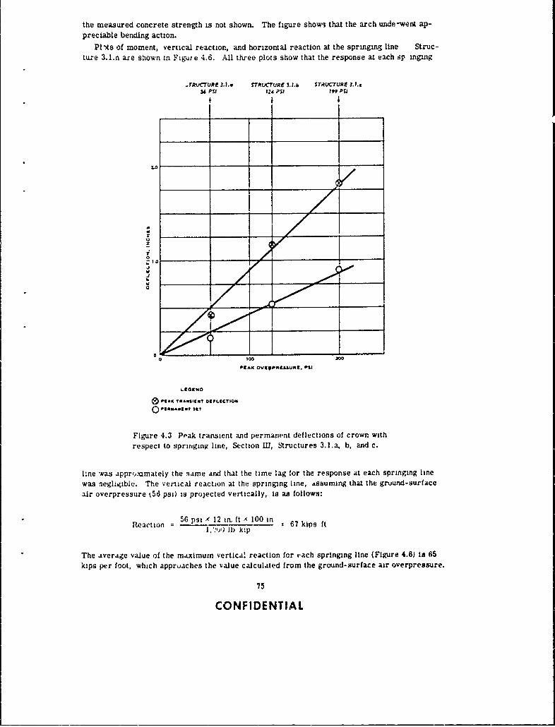
the measured concrete strength is not shown. The figure shows that the arch unde -went ap-preciable bending action.
Pi-s of moment, vertical reaction, and horizontal reaction at the springing line Struc-ture 3.l.n are shown in Figu;e 4.6. Ql three plots show that the response at each sp inging
.rRUcTuRE 3. .. STRUCTURE 3.l.b ST,CTURE 3.l.c56 PSI 124 PsiI i~PSI
__________K ________URZ P111 _ __ _
..
PtAXMAWS2MV0PLICT10S
14
QI V4**AW"E sa
Figure 4.3 Peak transient and permanent deflections of crown withrespect to springing line, Section I1, Structures 3.l.a, b, and c.
line was apprommately the same and that the time lag for the response at each springtng linewas negligible. The vertical reaction at the springing line, ,ssumlng that the gruund-surfaceair overpressure t5 6 psi) is projected vertically, is as follows:
Reaction =5ps' 12 inft 67 kips ftl)b kip
The average value of the maximuin vertical reaction for each springing line (Figure 4.6) Is 65kips per foot, which approaches the value calculated from the ground-surface air overpressure.
75
CONFIDENTIAL
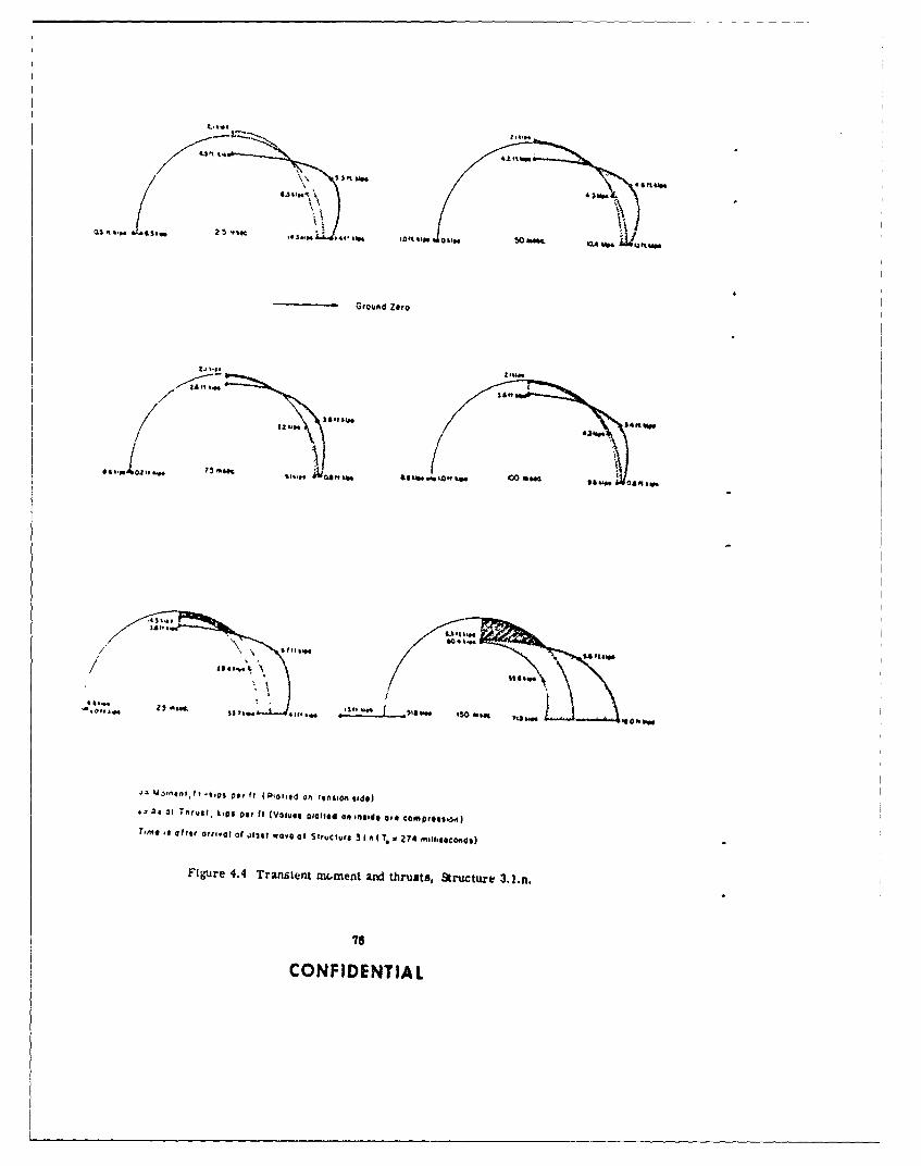
4J',
130 p106A m"t
40,, Wo,"Hen
*2A23 T rs.k,6prf (V lys, 0101,4 0, Com ft l
T~m* e al sr friv l 0 jf-jt ave f S ru~l ro 1 A . a274 nol.66l.dl
Figure ~ ~ ~ ~ ~ ~ ~ ~ ~ ~ ~ S 4. rnintmmn n trss tucue32n
43%.7.
COFIENIA

Ground Zero
2S1. 64 25 mine. =%. I SAas 250 *Mog V1"' &M "
131tito24 I-M
Figure 4.4 Continued.
A comparison of this ALverage value and calculated value indicates th4l the vertical1 componentof earth pressure on the structure is, &or practical purposes, e-jial to the ground-surface airoverpressure directly above the structure.
4.3 RADIATION
A metnod of predicting gamma r.~dlation within buried structurns (presented in Reference 13)was used to predict the average radiation within the fcuur structures The method assumes thatradiation will follow the pat' of least resistance, and thus it is assun-ed that the radiation ex-perience' right-angle turns as illustrated In Figure 4.7. It Is also assumed that one righ-angleturn attenuates radiation by a fa .tor of YVU or (8.7 x 10-i) and that two right-angle turns attonuato
77
CONFIDENTIAL

0
~~1 ______________ I _______ _____0
_____ ~ ~ ~ ~ ~ ~ ~ ~ ~ ~ e __ _ _ _ _ _13__ __ _ _ _ _ _ _ _ _
10
71-
IL0
10
0 0
11 0
,OOJt~ld';dW %sum0
____ _ _ 078
CONFIENTIA

'5
Momentt (ereu) Tme
?5
E 0c
3 50 100 iS0 200 250 500 340 40
Time, MillisecondsVeMom ecti versus Time
Z S>0. %_ _ _ _ _ _ _ _
>-2
3 50 100 050 200 250 300 350 400
Time. \4i11,Second$
Verti Reaction versus Timet
zerime * 274 milisecond
Figure 4.6 Transient springing line reactions for Structure 3.1.n.
79
CONFIDENTIAL

WTUR~N IN RADIATION
--wWALL AftCA-6.7 SQ FT
D0oqWAY ARAI1G3 Sa FT
LL*
WUA TUR INAOA'AION
8 INCH THICKNESS
dl
b. TRANSMISSION THROUGH EARTH COVER AND CON -RETE
Figure 4.7 Assumed transmission of gamma radiation into the 3.1 structures.
80
CONFIDENTIAL
it by a factor of '.30 or (5 x 10⁻³). lIn addition, it is also assumed that radiation is attenuated by
the ratio of entranceway area to wall area. The atte-ua,,on factors for materials such as con-crete, steel, etc., are determined in Reference 14.
Since radiation enters structures of the 3.1 type in two ways, (1) through the entranceway,and 2) through the earth cover xid concrete arch aect!)a, the ,tternution factors for the twopaths of radiation must De determined. The calculations are as foiivws:
The -.ttenuation factor (At) for entranceways can be determined by means of the following
formula:
At z AdIAsIAa
In this formula, At = total attenuation factor
Ad = attenuation caused by two right-angle turns in radiation
transmission = 5 A 10- 3
A* attenuat:on factor for 4 -inch steel plate 10- 1
Aa = attenuation eifect determined by the ratio of entranceway area
to wall area = 16.3 It' - 83.7 ft' = 2 x 10⁻¹
Thus, At is determined to be 9 x 10- 4 .
The attenuation factor (Atd for earth cover and concrete arch can be determined by meansof the following formula:
At = Ad Ae x Ac X Aa
In this formula, At = total attenuation factor
Ad = attenuation cau .ed by one 90-degree turn in radiationtransmission = 6.7 x 10 - 2
Ae = attenuatioi factor for 48 inches of soil = 5 x 10⁻¹
Ac = attenuation factor for 8 inches of concrete = 3.5 x 10- 1
Aa = area effect !'/ d - d = 3.1 x 10 - '
Thus, At is determined to be 3.9 x 10⁻⁵.
The attenuation factors, as calculated above, were used to predict the radiation within thestructures and the resulti'.g values are shown in Table 4.1 along with measured radiatlon valuestaken near the center line of the structures. It is interesting to nc.e that the predicted values ofinternal gamma radiation intersect the curves shown in Figures 3.12 through 3.15 at distancesof 5 to 8 feet from the entranceway.
4.4 ACCOMPLIS)IMENT OF OBJECTIVES
The general and specific objectives listed ii Chapter 1 are repeated here along with a state-ment regarding how well thny were accomplished.
General Objective. "To determine the suitability of underground concrete arches asprotective 5heters as well as their resistance in the high-uverpressure ranges (50 to 200 psi)
"The use of a "radiation-window" width cf d/3 is arbitrary. It represents an attempt tofind a correlation between the increase of "window" width and an increase in attenuation dueto increased soil thickness.
81
CONFIDENTIAL
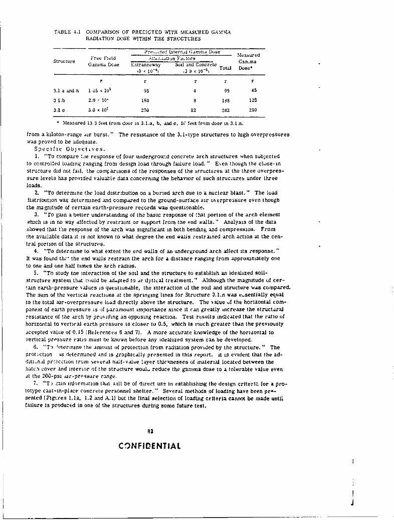
TABLE 4.1 COMPARISON OF PREDICTED WITH MEASURED GAMMARADIATION DOSE WITHIN THE STRUCTURES
Prr.,:tcd Lnternd Gammrnr Dose M dStructure :-e Fluld A;.jin F.or!Gamma
Gamma Dce Entranceway Soil and Concrete9 10-) 3 9 , 0-5
) Total Dose*
r r r r r
3.1 a and n I 5 10i 95 4 99 45
3 1.b 2.0 10' 180 8 188 125
3.1 c 3.0 I0- 270 12 282 210
4 Measured 13 3 feet from door ,n 3.1.a. b, and c, i" feet from door in 3.1.n.
from a kiloton-range air burst." The resistance of the 3.1-type structures to high overpressureswas proved to be adequate.
Specific Objectives.1. "To compare .Lie response of four underground concrete arch structures when subjected
to controlled loading ranging from design load through failure load. " E~en though the cluse-instructure did not fail, the comparisons of the responses of the structures at the three overpres-sure levels has provided valuable data concerning the behavior of such structures under threeloads.
2. "To determine the load distribution on a buried arch due to a nuclear blast." The loadlistribution was determined and compared to the ground-surface air o erpre.sure even thoughthe mag '.tude of certain earth-pressure records was questionable.
3. "ro gain a better understanding of the basic response of :hat port ion of the arch element.,h~ch is in no way aifected by restraint or support from the end walls. " Analysis of the datashowed that the response of the arch was significant in both bending and compression. Fromthe available data it is not known to what degree the end walls :estruned arch action at the cen-tral portion of the structures.
4. "To determine to what extent the erd walls of an underground arch affect its response."It was found thi" the end walls restrain the arch for a distance ranging from approximately oneto one and one hall times the arch radius.
5. "To study tne interaction of the soil and the structure to establish an idealized soil-structure system that -ould be ad.pted to ar ilytical treatment." Although the magnitude of cer-tan earth-pressure talkes is questionable, the interaction of the soil and structure was compared.The sum of the vertical reactions at the springing lines for Structure 3.l.n was e-sentially equalto the total air-overpressure Load directly above the structure. The value of the horizontal com-ponent of earth pressure is A paramount importance since it can greatly increase the structuralresistance of the arch by providing an opposing reaction. Test results indicated that the ratio ofhorizontal to vertical earth pressure is closer to 0.5, which Is much greater than the previously
accepted value of 0.15 (References 6 and 7). A more accurate knowledge of the horizontal tovertical pressure ratio must te known before any idealized system can be developed.
6. "T9 etermine !he amount of protection from radiation provided by the structure. " Theprotection is determined and is graphically presented in this report. it is evident that the ad-d.ti-n.d prrection ironi ,everal nalf-value layer thlcknesses of material located between thehatch cover and interior of the structure woul, reduce the gamma dose to a tolerable value evenat the 200-psi ,ir-pressure range.
7. "T ,ain information that x ill be of direct use in establishing the design criteria for a pro-totype cast-in-place concrete personnel shelter." Several methods of loading have been pro-sented (Figures l.la, 1.2 and A.1) but the final selection of loading criteria cannot be made untlfailure is produced in one of the structures during some future test.
82
CONFIDENTIAL
4
Chco/et 5
CONCLUSIONS and RECOIVENDATIONS5.1 CONCLUSIONS
The following conclusions are babed on the behaior of :he soil-struc.ture combination de-scribed herein and are limited to similar combinations subjected to similar loads.
The 3.1-type structure pro, td to be n adequate shelter for resisting air o~erprecsure of upto 200 psi, thereby h, v'ng tha . an underground reinforced-concrete arch is an excellent types:ructure for use in prv.d:ng protection against nuclear-blazt ,,/ects.
A reasonable design methud for underground arches cannot be developed until more is knownabout the dynamic properties of soil-structure combinations. In this ca.e it was observed thatthe earth pressure dmtribut.on around the relatively stilf arches were nonuniform and slightlyasymmetric, thus causing the arch to undergo appreciable bending. The transient earth pres-sures exerted on btructures of this type were greater at some pointe than the ground-saurfaceair overpressure. This seems to be due to a combination of reflected and passive earth pres-sures.
The earth-overpressure dibtribution around a relatively rigid arch structure is nonuniformand the arcn element undergoes appreciable bending.
The horizontal earth pressure resulting from ground-surface ar overpressure is apparentlygreater than had been previously anticipated.
Displacement of the 3.1 .,ructures as a whole, as well as the -elative deflection L- :ie crown,is directly proporti'nal to the overpresbure. During transient loading, a test structure buriedin the Frenchman Flat soil moved at approximately the same rate and magnitude as the free-field surrounding soil.
The end walls affect arch 4ction for a distance of about 1 52 time,; the arch radius.Strain gage measirements of the test structure at the 56-psi level yielded valuable informa-
tion for determining moments and thrusts in the arch. Plane sectior, before loading remainedplane during loading. The vcrtical reaeticns at the springing line were approximately equal tothe ground-surface air uverpressure times the vertical projection of the arch structure. Thelargest moments and thrusts occurred near the springing line, and this would be the prooablelocation of any failure.
The simplo entranceway used for the structures sealed out the air pressure. It was not de-signtd to attenuate radiatiun and thus aid not provide adequate radiation protection for personnel.
At high-pressure levelk (greater than 100 ps'l, floor slabs that are monoitl'ic with the archreceive relatively high magnitude loads and accelerations, which may make it necessar, to useshock-mounted floorng in order to reduce possible adverse phys.ological effecte.
5.2 RECOM5 ENDATIONS
it -s recommendea !hat the use of footings be investigated for arch-type struLtures. The floorslab ol the structure could be mace much thinner and poured separately, then joined to the footingwith some tyne of flexible water seal. This method of connection would most likely reduce theinduced acceleration to the floor slab caused oy the air-induced grornd shock. The design meth-od as shown in Reference 5 may continue to be used until refinements to the procedure are de-termined or a new procedure is presented. The significant bending measured in Structure 3 .l.aipoints out thzit the procedure which is based on compression solely from the dynamic load maynot be as conservative as believed previously. The entranceway should be modified for ac ial
83
CONFIDENTIAL
use to reduce the radiation admitted to the interiur of the structure. This culd be accomplishedin several ways, dependig on the intended use of the structure: one method would be to use the
existing entrareway but add baffle walls within the structure, another would be to utilize an
entrncew-ay separated from the structure by at least one 90-degree, horizontli turn.The 3.1-iype structures bhouid oe exDosed to much higier overpcessures durug future tests.
Deflection measu:ements to determine cutwa-rd movement of the springing line should be made,in addition to deternanauions of the excursionb of points located at 30, 45, 60, and 90 degreeson the arch intrados. The apparent success of using strain gages in determining reactionsshows the usefulness of thib type of gage for use in future tests.
The results of the s..nple model tested in the laboratory points up the possibility of this typetest in determining: !aiiure modes, deflecticn patterns, the effect of various soil types on theultimate load-carrying Lapacity of structural elements, and the verification of design methods.It is recommended that a model tebtng program be initiated and also that full-scale tests be.onducted to verify the predicted valtes obtained in the model tests. Since the cst of buildingand testtng models is ;mall compared to the cost of prototype structures, a large number ofmiodel tests could be performed so that statistical results for a wide variety of test conditionscan be obtained.
84
CONFIDENTIAL
Appendix A'
IDEALIZED LOADING CRITERIAFurther analytcal development and tests resulting 17) is a reasonable way of providing the necessary re-
in structural failures will Lc required to vurif) the sist . e against se-'eral possible types of failure.adequacy of any method of ,aha~atlng the uerpressure Som. of these modes may not be critical fI,- a given
required to cause collapse of a buriLd ar-h. In the in- arn shape or span, but, nevertheless, should be in-turitm, any recur.i.nendations for luair-, , r ni .,t cluded to avoid overlooking a critical condition in
le conidered to be tentatil.e. other cases.
To De acceptable, any criteria presented should in-Further analytical development and tests resulting in lude one or more loadings producing bending in thestructural failures will be required to vt-r~fy the ade- arch in order to provida a minimum fiexural strengthcuacv of an) method ot calculating the overpressure which might otherwise be lacLking. The difficulty lies
required to cause collapse of a buried arch. In the in- in determining just Ahat this minimum should be.terim, an) recommendations for loading criteria must There appears to be no ulternatave to basing this estihe considered to be tentative. mate on a guess as to the collapsing overpressure for
these arches.
A.1 DISCUSSION Three loadings, designated A, B. and C, are pre-sented (Figure A. 1). the first being identical with Load-
It is possible to develop analyses accounting for 'he ing (la' ) of Reference 16. Loading 3 altere Loadingcontribution of passive soii pressure to the resistance (Ib' ) of Referente 16. reducing its severity by iimit-of the arch whlch are rigorous to the extent of provid- ing the amount of thrust to be conhidered in combina-ing a soil reaction in the region of outAard movement tion with the bending moment. This gives a resultwhich is proportional to the radial achection. Refer- more nearly in accord with the cor.clusion. based on
,nce 3 pr :aented a less sophisticated attcmpt to account the permanent x.eformatic; pattern of Structure 3.1.c,for this passive soil erebature by use ot an inward act- that lailure will not occur in an antisymmetrical mode.
in, soil Icading at tne haunches. A correlation ot either Loading C is a variation of loading lIc' ) of Referencemethod with test results to provide worthwhile loading 16. modified to predict the anticipated collapsing over-criteria does nut appear to he practical it this time. pressure for this irch. Provisions are included for
Serious consideration was aiso gr~tr, to the possi- considering the transient na.ure of Loadings B and C.bility of using a simple variable to expi ass the inllu- In the case of semicircular arches the bending mo-
ence of arch flexibility and soil properties. This ap- ment from Loading C is very much less than that whichproach was found to be !mpractical in the present would be obtained with the same peak overpressurestate of the art. due to th,2 impossinility of assigning uniformly distributed over the horizontal projection ofa definite numerical value to this variable, the arch. Most of this reduction is attributable to the
Methods which fail to account for arch flexibility buttressing action oi the soil around the hauncnes. Inand ,oil priperties iay not result in optimum design the case of flatter arches tWis action may not be devel-of -rcnes .vith la-4e rise to ,pan ratios. However. oped to the degree attained in A sem:circular arch. Or.nhil he a, iables ,toled an he l)r ,perly iaobated the other hand. as the rise to span ratio decreases, the
thuse methods seem to be nec essary. and are probably bending momcnt f.om Loading C begins to approach and
itdquate provided that 11) sulitRicnt duetiiity is pro- finally exceeds, that , tch would be obtimed with thz: in the arch to permit large ,hfl'ct,uns without peak overpres.suie uniformly (itributed ,over the hor-,olihpse. and '.) ,suitable tackilli nr-.',ry compacted. izontal projection, .o that the influence of buttress
i, jed. Fsr arcne- higts h rise to iv.,, . ratios re- action b.,comes relatively I..ss important with d,,creas-
iuiremn., ti a' ma more imprt,.nt than providing a ing rise to span ratios. This creates an uncertain,ih moim nt c0..pc'itv. situation that % uld require further study, ind probably
rhe cunc-ol ,modal !oadings ttlcirences 16 and tests, for clarification. Because of this, applicability
of ti.e criteria given here to arches Ihaving rise to span
U.ing the Iata from AppI ndix B. the firm ol Holmes rtos (,f less than about "', ma be quest inable.4nd Narver, In.. , perf,,rmvil i p.,tbhot anal, .,is for In establishing the rebi:tanc e of the arch for blast
ALb dReference 15). The mo.t Aignilf.ant results loading conditions ultimate strength methods should bewere the idealized lhadeing ( .taria contained in Chap- used which account fur redistribution of moment due to
ter 5. whic.h has bcn ic-produced here as Appendix A. formation of yield hinges. Increased yield stresses
85
CONFIDENTIAL
Gz
........ 0# GaOLukD SuRIIACE
LOADING A
(A) COMPRESSION MODE
,7A)=
LOADING BI LOADING 62
(B) DEFLECTION MODE
L
LOADING CI LOADING C2
(C) COMPRESSION-BENDING MODE
Figure A.1 Recommendecd idealized loadings.
86
CONFIDENTIAL

appropriate to dynamic loading should also be used. corresponding to the crown of the arch and to haveif me proportions of the structure inalcate appreciable the same support condition at the other end as thatahiill action. this should be accounted for In the design, existing at the base of the arch. The period of vi-.'nd the structure should be reinforced as required to bration should allow for the weight of earth covercarry shed stresses .n addluon to those resultivg from over the arch between crown and springing line. and,trcn actiun. for the effect of axial tarust.
When the relative amounts ot thrust And momentIt shuuld be emphasized that in practice this loading place the arch section in the compression regime.
cr'terma, or any other aimed at predicting the collaps- the gross concrete section should be used in com-ing overpressure, may not control the design. Do- puting the period of vibration.penuing on the occupancy or function, the structure Due to the short duration of this load condition.may become unserviceable at an overpressure much buckling may be ignored.less than that correpondag to total collapse. Loading C (Compression-bending
Mcde): A combined leading (Figure A.ic) consist-ing of parts Cl and C2 as follows:
A.2 RECOMMENDED LOADS I. A uniform radial load acting inward, and overthe central one third of the length of the arch axis.with a uniform radial load acting outward on the outer
The following three load conutions are recom- thirds. The intensity. Pcb. of the load on the centralmended for design of completely ouried reinforced one third of the arc should be varied as a function ofconcrete arches. the length. a. of the arch axis, and the span. L. ac-
Loading A (Compression Mode): A static cording to the formula:
uniform radial load acting inward with an intensityequal to the peak overpressure at .he ground surface Pso(Figure A.la). Pcb =
Because the period of vibration of the arch in thistype of loading is relatively short compared to the rise
time of the overpressure. the overpressure should be 2. In combination with load Ci. a uniform radialregarded as a steady state load rather than a transient load acting inward over the entire periphery with anload. The factor of safety against buckling should not intensity equal to the peak overpressure at the groundbe less than 1.0 and the axial thrust should not exceed surface.the yield capacity of the arch section. The load C1 should be considered to have the same
Loading B (Deflection Mode): A corn- variation with time as 'tit of the overpressure on the
bined loading (Figure Alb) consisting of parts Bl and ground surface. In lieu of this, an equivalent linear
B2 as follows: approximation of the variation with time may be used.The load C2 can be considered as a steady state load.
1. A uniform rad'al load acting inward on the s.le The required resistance should be computed byadjacent to the blas,. Acting simultaneously with a considering loading Cl as a dynamic rather than auniform radial load of the same intensity acting out- s*atlc load.ward :n the far side. The intensity of the load should The period of vibration for this loadir conditionbe equal to 50 percent of the peak overpressure act-ng at the ground surface. should be computed as that of a simply supported
beam with a span equal to ore third of the total length
2. In combination with load BI, a uniform radial of the arch axis, and should allow for the weight ofload acting inward over the entire periphery with an eartn over this portion of the arch, tzd for the effectintensity equal to 50 percent of the peak overpressure of axial thrust.acting at the ground surface. only the central portion of the arch should be in-
With negligible error, the ioad BI can be assumed vestigated. assuming simple support at the points ofto decay linearly from the initial peak value to zero load reversal. The effect of thrust from load C2 onIn the time required for the shock wave to travel moment capacity and buckling of the arch should beacross the structure, and the load B2 can be consid- considered.ered as a steady state load. If the relative amounts of thrust and moment place
The required resistance should be computed by the arch section in the compression regime the grossconsidering 'oadlng B1 as a dynamic rather than a concrete section should be used in computing the pe-static load. For analyais purposes the period of vi- rinod of vibration ad the critics! buckliC load.bration of the arch for this losding condition can be Tae resistance of the outer thirds of the archcalculated as that of a beam with a length equal to th should not bo less than that provided in the centraldeveloped length of the arch from springing line to portion.crown. Consider the beam to be hinged at the end Application of this loading criteria, neglecting
67
CONFIDENTIAL
satil , tion, gives the foliowing results for these (1) using a low value for tn estUmated effective dura-
4rebes: t:cn LA fhe .,verprtssure. (2) , ,-ng the gross concreteAoproximate bection In calculating moment capacity, neglecting the
L.,dlng Collapsi rg C.erpr.:ssure (psi) steel, and 13), neglectang Duckling Neglectiag buck-
A L.ng may oe realtoc .-,r a . urt bpfn bemicircular.r(.n, .ut it is bcaicvrd Las.t b5ukhrg sh,-ld be con-
C 31l to 370 md.ercd for longer spans.Th- ! wer limit for Wading C is cbtaned by, (1)
!The aoove collapsing overpressures for the 3.1 arch using a higher estimated valie for the effective dura-gtructures are based on a concrete strength of 4.t£0 tion of the overpressure. 12) us,g the cracked bection
psi ad a dynanic increaae l.ctor of 33 percent. The in calculating moment capacity, and (3) considering
otre-aes Iue La dead k,ad are nt glected. ) bucking.LuauLng " gives the critical condition for these Loading C predicts a substantial decrease in col-
arches. a-d probably woild .ntrol in nearly all other iapting overpressure under , long duration pulse.
cases. The upper limit for L.ading C is oLtained by,
8C
CONFIDENTIAL
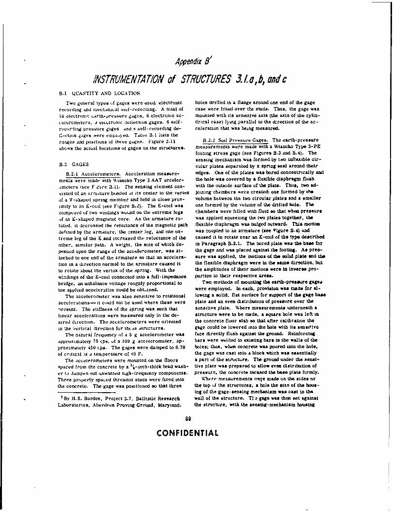
Aj endx 8'
INSTRUMENTAT/OW of STRUCTURES .5. /a,b, and cB.1 QUANTITY AND LOCATION
Two general types if gages were used. electronic holes drilled in a flange around one end of the gagerecording And .necn~acal scif-recorcang. A trial of case were fitted over the studs. Thus, the gage was16 eiectronic arth-,rehbure g.ges. 6 electronic ac- mounted with its sensitive axis (the axis of the cylin-cierometers, J tni,,.tronic deilection gages. 6 sell- drical case) lying parallel to the direction of the ac-recor'nmg presbure gages and s belt-recording de- celeration that was being measured.
q..ction .sges were cmph.,y ed. T.bie B. I ists therat.ges ad pobitionas of Lee.b gages. igure 2.11 8.2.2 Soil Presure Gages. Tha earth-pressure
shows the actual locations ot gages on the structures. measurements were made with a Wiancko Type 3-PEfcoting stress gage (see F:gurea B.3 and B.4). Thetensing mechanism was formed by two inflexible cir-
B.2 GAGES cular plates separated by a spring seal around their
B.2.1 Accelerometers. Acceleration measure- edges. One of the plates was bored concentrically and
menzs were made with 'Ai ancko Type 3 AAT acceler- the hole was covered by a flexible diaphragm flush
emetrs (see F nire 3.1). rhe sensing element con- with the outside surface of the plate. Thus, two ad-
saisted of an armature bonded at its center to the vertex Joining chambers were created: one formed by tiM
of a V-shaped spring member and held in close prox- volume between the two circular plates and a smaller
imity to an E-ccil (see Figure 8.2). The E-coil was one formed by the volume of the drilled bole. The
co(posed of two windings wound ou the extreme legs chambers were filled with fluid so that when pressure
of an E-bhaped magnetic core. As the armature ro- was applied squeezing the two plates together, the
tated. it decreased the reluctance of the magnetic path flexible diaphragm was rulged outward. This motioc
defined by the armature, the center leg, and one ex- was coupled to an armature (see Vgure 5.4) and
treme leg of the E and increased the reluctance of the caused it to rotate near an E-codl of the type described
other, similar path. A weight. the size of which de- in Paragraph B.2.1. The bored plate was the base for
penoed upon the range of the accelerometer, was at- the gage and was placed against the footing. As prea-
tached to one end of the armature so that an accelera- sure was applied, the motions of the nolid plate and the
tion in a direction normal to the armature caused it the flexible diaphragm were in the sme diroctlon. but
to rotate about the vertex of the spring. With the the amplitudes of their motions were in Inverse pro-
wndings of the E-coil connected into a full-impedance portion to their respective areas.
bridge, an unbalance voltage roughly proportional to Two methods of mountin the earth-pressure gagp,
tne applied acceleration could be oblit-ned. were employed. In each, provision was made for al-
The accelerometer was also sensitive to rotational lowing a solid, flat surfsce for support of the gage base
accelerations -it could not be used where these were plate and an even distribution of pressure over the
-resent. The stiffness of the spring was such that sensaive plate. Where measurements underneath a
linear accelerations were measured only in the de- structure were to be made, a square hole was left t4sired direction. The accelerometers were oriented the concrete floor slab so that after calibration the
in the vertical direction for thLae structures. gage could be lowered into the hole with its sensitivrThe natural frequency of a 5 g accelerometer was face directly flush against the ground. Reinforctng
approximately 70 cps, I, a 100 g accelerometer. ap- bars were welded to existing bars in the walls of the
proximately 450 cps. The glges were damped to 0.70 holes; thus, when concrete was poured into the hole.
of critical at a temperature of 10 F. the gage was cast into a block which was essenUallyThe accelerometers were mounted on the floors a part of the structure. The ground under the ienats-
,paced from the concrete by a 3/ -ich-thick lead wash- tive plate was prepared to allow even distribution of
er to dampen out unwanted tugh-irequency components. pressure, the concrete incased the base plate firmly.
Three properly Spa.ed threaded studs were fixed into Wheri, measurements were made on the sides orthe concrete. The gage was positioned so that three the top of the structures, a hole the size of the hous-
Ing of the gage-sensing mechanism was cast in tho'By 1I. S. Burden, Project 3.7, Baillitic Rexearch wall of the structure. TI c gage was then set against
Laboratories, Aberdeen Proving Ground, Maryland. the structure, with the sensing-mechanism housing
89
CONFIDENTIAL
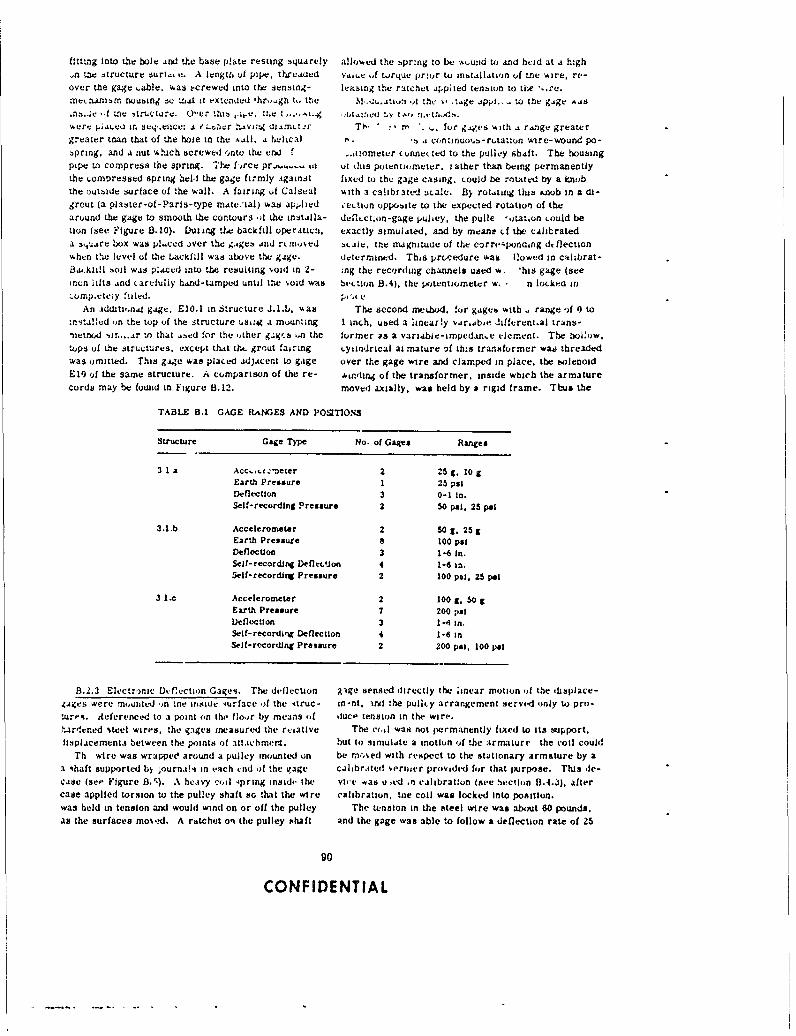
fitting Into the hole and the base plate resting squarely allowed the bpr.-ng to be-- %wund to anid held at a high,.n Tuie structure sun... v. A length of pipe, threaded va.iuv of torque priour to install..t.'n of tne wire, rt--over the gage .able, was ±.crewed into the sensing- ltiiaing the ratcrict q4p1ied tension to the .- emetanisn noubing so uid it e-cnaed 'hro..gi t,,M,.~, tthe . .tge ..ppi.. to the gige ..as.ns..2e -f Ule '4truct.'e. Q1ILr this ,i. th~e I-"-1, 'WIv *t.i:' Y t.'P otwere .ai~v in seq .eacv: 3 .' .. ar :tavi:g T~tr T)- r"nr. for g~ges with a r..ngu greatergreater than that of the hole in the A..ll, a thlcal ft. b .1 con~inuoosb-rotatton wire-woXund po-spring, and a nut which screwed onto the ern3 f -r ometer c nne( ed to the pulley Shaft. The housingpipe to compress the spring. Thel: U-rce pr.-~... &i oi tbis potentiometer. rather than being permanentlythe Loingressed spring held the gage firndly Against fixed to the gage Casing. could be rowued by a knobthe outside surface of *he wall. A fairing uf Calsual with a calibrated :scale. By rutilng this Knob in a di-grout (a pl aster-of- Pari s- type MAte.-ial) was app.lied 'ectiun opposite to the expected rotation~ of thearuund the gage to smooth the contours of the inalla- defleCun -gage pulley, the pulle -ota-ton could bettin (see Figure 8.10). Duriing the backfill operaticat. exactly simulated. and by meane cf the cAlitrateda 3tuAare box wasi pl..ced .)ver the ,;.gt:! and rt n'Aed bcaie. the magnitude of the corri-'.ponaing dt flectionwhen the level of the Lackfill was above the gage. 4.etermined. This prtcedure was flowed in calibrat-dBa.itiil boil was placed Into the resulting void in 2- :ng the recording channels used w, *his gage (seemni lifts ..nd (arefully hAnd-Limped until tthe %oid was twction 8.4). the Vnentiorneter w, n lockea inLornp~ete~y filed. pik V
An adds(on~s gage. E10.1 in Structure 3l.1.11. was The second meihod. !or gages with .. range of #) to:ni-t~a!:cd on the top of the structure using a mounzing I inch. used a linearly var.abje .iiferent.al trans-nizetnod ',ir .... Ar to that .ased for the other ga g'.s ..n thc former as a vaniabie-impedan..e eiement. The bolow.tops of the structures, except that tht. grrut fairing _yiindrical ai mature if this transformer wao threadedwas omitted. This gaige was placed adjacent to gaige over the gage wire and clamped in place. the twlenoidEli) of the same structure. A comparison of the re- .etr.'ling of the transformer, inside which the armaturecords may be found in Figure 8.12. moved axially, was held by a rigrd frame. Thuis the
TABLE B.1 GAGE RlANGES AND POT10NS
Structure Gage Type No. of Gaiges Ranges
3 1 a Acc-tz.,.neter 2 25 g. 10 gEarth Pressure 1 25 psiDeflection 3 0-1 in.Self-recording Pressure 2 50 psl. 25 pal
3.1.b Acceleromneter 2 50 g, 25 gEarth Pressure a 100 PaiDeflection 3 1-6 In.Self-recordirg Deflemtioo 4 1-8 in,Self-recording Pressue 2 100 psi, 25 p4i
3 I-e Accelerometer 2 100 C, 50 gEarth Pressure 7 200 psiDeflection 3 1-4 in.Self-recordinq Deflection 4 1-45 inSelf-recording Pressure 2 200 psi. 100 Pat
8.2.3 Electrr..c Durfection Gagesi. The deflection &-tge sensed directly the linear motion (if the drsplace-.taices were mrnied 41n tne ins~ide iirface of the itruc- in-nt. 'ind the pullty arrangement servo.d oinly to pro-tures. dieferencmd to a point on the floo.r by means of duce tension in the wire.hairden~ed steel wires, the gages mneasured the rtsative The c(,il was not permanently fixed to Its suipport.lisplacementi between the points of attaichmnt. but to simulate a motion of bhe armature the c'oil could
Th wire was wrappee around a pulley mounted on be moved with respect to the stationary armature by aa shaft supported ls journak. in each end of the ivage calibrated vernier provided for that pujrpose. This de-case (see Figure B.). A heaivy codl 4pnrig inside the vic'e was u ,ed .n calibratlon (see SeclIon 8.4.3). aftercase applied torsion to the pulley shaft so, 'hbat the wire calibration, tie coil was locked Into position.was held in tension and would wind on or off the pulley The tension in the steel wire was about 60 pounds.as the surfaces mo%.d. A ratchet ont the pulley shaft and the gage was able to follow a deflection rate of 25
90
CONFIDENTIAL
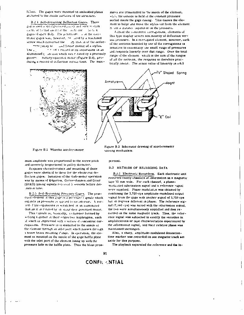
ft/b'ec. The g.ogea were mounted (in em~bedde~d plates sures are transmitted to *he inside of the elcment.wic4ILred to the rbaidc -jur!,ocub of tne 4tru. Cure. ... tfle ojutbito is hed itt the constint pressure
8.2 4 SLtacrigDeflection Giges. These se?..ed inside the gage cabing. 'this causes the ele-% *ir7 e ', -, mernt to bulge ia most' the !stylub 'iut from the element
A! Z m frt a Jistancx Jeopendo nt on the prusdie.* it a .. 5.. r t *.. tx ,,hout the toncvntric torr~gtansl. ele mrentb f
tr ,nic~~ ~ ~ gie ws vc~r. _,d ,y i rrdthined ... s type wiisplay 5evere nonarnearity of deflection ver-
t.re ts,,h c ni1 vdth ) uS n utU5j kieti'c sub pressurc. In a corr.ga"e element. nowever. each
:cewwu. c~set to e !.ea motio of a ty~ls. of the: :ections bounded by one of the corrugationa is
*In i'le to mr )I.. i~ermti ux o tn xty i senszazve to cbsentiaisy ,ne small range of pressures*lfl -'-' ,tori i is ~.~uriofl Of ~ ,nd responids linearly over that range. Over the total
aluminized ; Is -Anich Aa r tated oy a precisely range 'if the element whi.ch is the sum of the rangesgover". buttery-opetattd mrntwr (Figire 8.6). PC')- Cf I ll the sections. the response is therefore prac-.uc& a record of dxlectioflnes tzme. The rnaxi- ticil:y linear. The Actuai value of linearity is :t0.5
Mr. M_ IV"Shaped Spring
Afrnraure \ eignt
Figure B.2 Schematic drawing of accelerometerFigLre B.1 WI'incko accele-ometer 'ienoirg mechanilsm.
mum amplitude was propo~rtional to ihe sicrew pitch percent.atnd inversely propoortional to pulley diameter.
Response characteristics and mounting of these B.3 MLTIIloDLS OF RE~CORDING DATAgagc-4 were :dentiL'al to) th',,e for the electr',nic de- B.4.l Electronte: Recorders. Each electronic unitflei on gcse. Initiation of the Iisk- motor operation recorded twenty channels of information on a magneticwas by means of Edgerton, Geroo'.ihausen and Grier tape 35 rmm wide. For each channel, a phase-(SGUG) timing signals r.'ce is.d 5 se'conds before Jet inolu,atecl informnation signal and a reference *:gnal,fiit.,f tiflW. were supplied. Phase modulatiin was obtained by
B-2.5 Seif-flecording Prebsurt. Gaigc'i. The prin- combining the 3.750-cpsa smplitude-modulated outputcpleli-ment -oi this , ige j4 a pi essure ( ipsule which signal frojm the gage w-th another signal of 3.750 cps
exp~ands as pressure Ai i;;",d t, its interior. It rec. but 1O degrees Jifferent in phase. The reference sig-,rd f Ire *apansions is -crat bed In in tiuminized nal (7,1)10 eps) wasi mtxcd with the information sikrnai.
dIizk as :t.s tta yi cu ie .vr1dmtr the two were simultaneously amplified and then re -This tapsule is. b.~ially. i ( himher formed by corde.d in the same magnetic track. Thus. the' refer-
N.lf~.mg together -it their -!.gv-a tAo) diaphragms, each ence signal was subjected to exactly the variation In)f Aitch is *mpreqqed Atit ieriea oif koncentric cor- amplifications or tape characteristic$ PAsperienced byrugazons. Presiure is i insmitted to the inside o1 the information signal, and their relative phase wasthe --ennt through an inlet po~rt Ahich paisae% thr'ntgh maintained unchianged.A h-asvy brass mowanting :ine.In tpuratian, the ele-- Also. a sharp, Amplitude-modulated detonation-ment is mounted on the inside of the gage baffle plate time marker was recorded on one magnetic track setwith the inlet port of the element lining up with the aside for this purpose.pressure hole in the baffle plate. Thtus the blast pres- The playback separated the reference ard the in-
CONFR <NTIAL
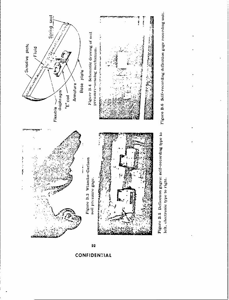
-0-J
3 C
t-Q 0
U.. 51..,
. .2
4 C)ENNA
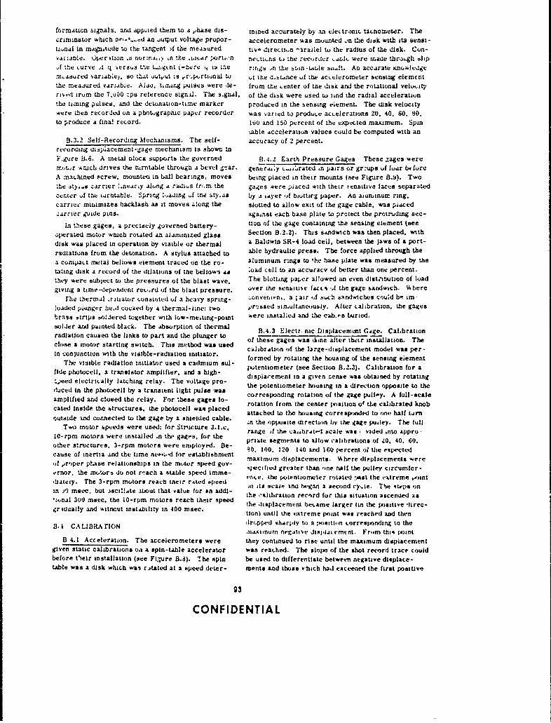
formation signals, and appixed them to a phbase dis- mined accurately by ani elettronc. tatnometer. The,crimnstor wichb t~,'- an output voltage propor- accelerometer was mounted ,a the disk with it3s ensi-tiunal in mAgnitude to the tangent )f the measured tiv- direction -2rallel to the radius of the disk. Con-va; _tole. Uper ition .s normir.a. " .n the iati ar piorttf ner ti~ns ta the recorker .rl were inade thr,),gh til p,i the curve I q ersws trne tL;gkrit (-ticre 't L3 '"~e rzri4!s *n the buin-t"te sil.An accurate icnuwledgem~aeured variab.e1 . so ttit uuyut ,s .rKrtioaito vi the 3.bstAnce f bhe accelcr-omettr bensing elemcntthe m~easured variable. Aldo, tiaanrg poises were de- from the .enter of the disk and the rotational velvi.tyrived irum the 7,00O cps reference signil. The s-guAl. of the dibk were used to find the radial accelerationthe timing pulses, and the detonation-time marker produced in the sensing element. The. disk velocitywere then recordeLd on a photographic paper recorder was varied to produce acLcrations 20. 40. 60. SO.to produce a fina! record. 100 and 150 percent of the expected maximum. Spin
..able acceleration values could be computed with an8.3.2 Self-lRecordirg Mechanisms. The self- accuracy of 2 percent.
recoratig aisplacement-gage mechanism is shown inF.gu~re B.6. A metal olocx support flt: governed B.-;.2 Earthi Pressure Gages These gages were.'rcwtr Arcd drives the turntable through a bevel - ar. genr ij~y c.-i~ratcd in pairs or grzups uf four btfureA mar hined Pcrew. mounteu in ball bearings. moves being placed in their mounts (seet Figure B.9~). Twothe sty l~i carrier :.nretriy along A radius frr.m the gages wvere placed with their iiinsitive faces separatedce.nter uf the tirntable. Spring bo aalng f tre sty..i5 by % LAyer Wf biottirg paper. An aiundnum ring.carrice mLiimizes backlash as it moves .. ong the slotted to allow exit of the gage cable. was placed,:arrier guide pins, against each base plate to protect the protruding sec-
In these gages, a precisely governed battery- ion of the gage containing the senslang element tseeQ perated motor wtuch rotted an aliminized glass Section B.2.2). This sandwich was then placed, withdisk was placed in operation by visible or thermal a Baldwin SR-4 load cell, between the jaws of a port-
radiation& from the detonation. A stylus attached to able hydraulic press. The force applied through thea compact metal bellows element traced on the ro- aluminum rings to the hase plate was measured by thetating disk a record of 'he dilations of the bellow'i as load cell to an accuracy of better than one percent.tht-y were subject to the pressures of the blast wave, The blotting paje'r allowed an even distribution of loadgiving a tame-dep'nd'nL rec-,rd of the blast pressure. over the bensbiti'.e facts -A the gage bandwich. %hbere
rhe .1hermal ritiator conzinitd of a heavy spring- coriverni.n,. a ;air ,if tsuch aaryviwiches c)ud be im -!oaded plung~er lhe.d cocked by a thermal-line: two pr--issed simultaneously. Alter ial.,bration, the gagesbrass 3trips *olljered together with low-mesting-point were intitalled andi the cah.es buried.solder and painted black. The atbsorption of thermal B.3 lcvn DsaemtGo.Clirinradiation caused the links to part and the plunger to8.3 lc.niDslaerutGg.Cabaio
clos. amoto strtin swtch Thi mehod as sed of these gages was (i.ne after thecir installation. Thecl-oe amtor sitrtvisitbh. Thaisatod ntasuse calibrAtion of the large-displacement model was per-
Tncnuciwt he visible-radiation initiatorue adimsl formed by rotatir the housing of the sensing eiement
fide photocell. a transisitor amplifier, andl a high- displaiemet ine aSientene was3) obalinbyoati ng
,,eed electrically latching relay. The voltage pro- thespacenimetehin in a ire otine oppottith
duced In the photocell by a transient light pulse was teptnimtrhuigi ieto poiet h
amplified and closed the relay. For these gages to- corresponding rotation of the gage pull-y. A full-scalecate inidethe trutars. te potoell as laci.1 rotation from the center position or ttc calibrated knob
catsied inide tone rcte s th ae photoce e w ab le attached to the housing corresponded to on-! half tirn
uTwid mndtor neted toete guse bor aahicdre c.1le, in the opposite direction by the gage puiley. The lull
Ta1 oo0peswr se:frSrcue3lc range )f the ca,ibrtto-l scale was.- vided into appro -I0-rpm motors were installed .n thi- gages, for the p~late segments to allow calibrations of 20, 40. 60.othier structures. 3-rpm motors were emiployed. Be- M. 100. 120 140 and 160 percent o the expectedcause of inertia and the time nee'i.'d for establishment maiu Iplcmn.Vheedpleetswr'if er'per ptase relationships in the motor speed guy- smacifu ied greae thas'n %herte dplaeyet wicmere
e'rnor. the motor,. do not r' ach a oitable speed immo- spcfe rtrthnoealtepueyicme-,!iaeiy Th 3-pm mtor rech heirr,4k.- rieed enice. the potentiomete: rotate.d -Ast ihe eXtreme x..int
in )9 mae. but )fjci!!.te aijut that value for an addl- ii the .sleation a fod his siuTion aseded as
'ional 300 mscc. the 10-rpm motors reach the-ir speed the 'lisplaeent ecamed lrgei the ptonsitiedec-
gridually and witnout instability in 400 macc.bedslcmtb# elagr(nhepiivife-lion) until the extreme point was reached and then
B-1 CALIBRA rlcN dri.pped tharply to a mmnition .orresixonding to the.mAiinum n.'giti'e disgiat c'mtnt. From thisq joint
B 4.1 Acceleration. The accelerometers were they continued to rise until the maximum displacementgiven static calibrations oa a spin-table accelerator was reached. The sinpo of the shot reco~rd trace couldbefore t'eir installation (see Fl,-ure 8.8). '!he spin be used to differentiate between negative displace-table was a disk which wal rstated at a ispeed deter- merits and those vhach ha exceeced the first positive
93
CON FIDE NTIA L
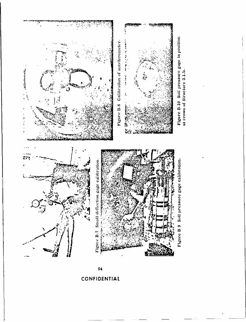
11
.:4
,05~
C .0 e.,
fyf~
tA -. :. 1,
CONFIDENTIA
extreme point. Negative displacements were handled their interpretation slightly more difficult. Threeb:mi:.arey. traces appear with no vizib'c recora. ard Although the
T e aoAel e'ti n gt,;e! .:u ja.Lratud oy .ang ;recordng .quipm,n.t gi-es . ery indication of havinga :ial micrometer as a bt.., ard to ineasure the moution operated properly, it is difficult to conceive of negli-oi the coil relative to its 3oppurt. After ,oosening the gible pressure existing at the corresponding gage po-clamp which held the :int:arly vari4ole tiferential sitions. Calibration steps applied immediately beforetransformer coil in pla:e. a slotted block which held and after the test :nterval show proper operation oftne m'cronotLr was slipped over the coil-suppor't ba, recording equipment. Anud the severe zero shift nor-
(set Figare 81 ) and locked in position. The coil was mally associated with fauy cables is missing. One
inov-d in a direction opposite to the actual deflection record was lost completeiy apparently because ofto produce calibration steps. Values. botn positive cable failure at detonation time.and r.egative. of 20, 40. 60. 60, 100. 120 and 140 per-cent of the expected ma.xlmum were uaed. B.5.2 Data Processing ind Interpretation. The
raw data was transcribed from tne oaciaogrdph trace8.4.4 Se'f-Recording Disp!acement Ga,es. These into digita form on punched cards to facilitate process-
gages were calibrated briore assemoiy )v installing Lng. The puncned cards were run thrrugh an electronica maxc, turning tne r-cordmtg met..Anism baaft tbrough digital computer zspecialiy programmed to linearizeone revolution, and measurirg the height of the step tao i ecords. The linearized records of earth pressure.
produced on the wsk. ',,th ta circumfereiice of the deflection, acceleration, and air overpressure ve.epu 'e, known, the displacement corresponding to this then replotted in final form for Structures 3.1.a, b,step neght was readily deduced. The gage -was linear, and c and are shown in Figures 8.11. 8.12, and b.13,
so that ie slope of the curve of stylus motion versus respectively.displacement obtained in this manner could be extended The interpretation of records having zero shifts a-over the full ra=ie of tne gage. blast-arrival time leads to some difficulties, In that
the exact course of the zero shift is often obscure.B.4.5 Self-Recording Pressure Gages. Calibration Experiments have shown, however, that when such
of the pressure capsuwes was )erformed by tbe manu- shifts occur the calibration curve is generajiy notfacturer. The calibrations were plotted using a Leads changed except that the zero valu.3 of the physicalNorthrup X-Y recorder. The output of a Statham qjantity being measured is at. ted to a new positionstrain-gage-type pressure tra.'sducer was led tirough along the curve. To correctly inte-pret records of.implifiers to the pen (X-axis) f the recorder. C-n- this type. It is necessary to determine from the call-sule deflection was measured by a n'ierometer head bration curve the site of the physical quantity repre-equipped with a null detector and servo system operat- sented by the zero shift and algebraically vubtract thising z slide-wire potentiometer which, in turn, con- value from every physical quantity value on the call-trolled the chart drive (Y-axis). The resulting pre- bratlon curve, and then to measure deflections on thesentation gave a plot of capsule deflection " a function shot record using the original system zero determinedof applied pressure. from the calibration record and relate these to physical
The disk drive motors were individually tested for quantity values using the revised calIbration curve.start-up time and speed, these chacacterIstics were The estftttes of calibration accuracy given In therecorded for each motor. bections on cauibratlon cannot be tpplied alrectly to
the test results because gages and equipment sublectedto the severity of a nwlear detonation may not functon
8.5 RESULTS lust as they do under the tranquil condltons of a static
1.5.1 Performance. The operation of Ove gage* calibration. For ,xampla, pressure gage& may be af-and recording equipnent is sumnmarized In Table 8.2. fected by accelerations, .nd without elaborate Instru-From a recordin4 standpcint, 21 of the 48 records are mentation, th mageitude and effects of the acceier~tonorsulered excelei.t. The majority if th remaining cannot be known. Consequently, such instrumentation
r,.tords are beset with siall te "o shifts which ,aga meawirzments made during nucletr Pata are generallyconsidered accurate to no better than 10 or 15 percent.
C5
CONFIDENTIAL
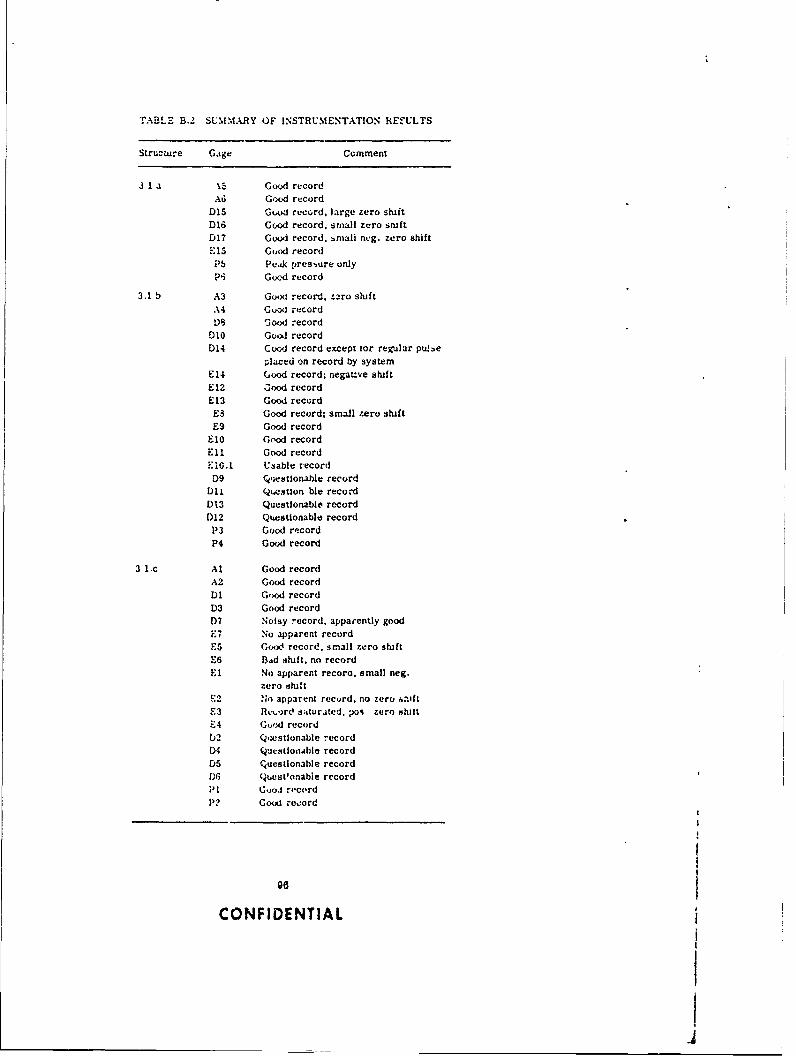
TABLE B.2 SUMMARY OF INSTRUMENTATION REfULTS
Structure Gage Comment
3 1 a \5 Good record
A"d Good record
D15 God record, large zero shiftD16 God record, small zero smftD17 Good record. bmali neg. zero shift."5 Good recordP5 Peak pressure only
P-i God record
3.1 b A3 Godx: record, z2ro shift
A4 Ghoo recordD8 Good record
D0 Gool recordD14 CocdJ record except tor regular pu.Ie
placed on record by systemE14 Good record; negauve shift
E12 .ood record
E13 Good record
E3 Good record; small zero shiftE9 Good record
El0 Good record
Eli Good recordE10.1 Usable record
D9 rqestionable recordD0l Qoostion ble record
D13 Questionable recordD!2 Questionable record
P3 Good record
P4 Good record
3 ic At Good record
A2 Good record
D1 God recordD3 Good record
D7 Noisy record, apparently goodE7 No apparent recordE5 Good record, small zero shift
E6 Bad shift, no record
El No apparent recoro. small neg.zero shift
E2 .b,) apparent record, no zero hftoftE3 Ret,)rd saturated, poi zero shllt
-4 Good record02 Qestionable record)4 QuestlollAble record
D5 Q'uestionable recordD6 Qest'onabie record
Pt (ooJ record
P? Goo record
CONFIDENTIAL
______________________________________ .6
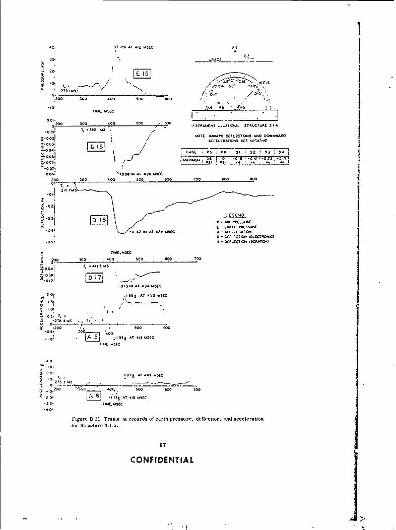
'C37 PSI AT 412 USLC P5
30 ,AOE _____
J20. I
T. - 01
0 \
200 300 400 $00 ,600
-10 *6,6 P
001' - __00____0. -0 300 40TRLAKNT -,AT<*5. STAuCTUftE 3 1 A
T. .392 :USNOTE INWAPD OE'LCCT'0kS ANO 00WNWA0
ACCELERLATON ARE PE'.ATIVE
;*- 4 AG 0 P5 OI -6042 33025
0 00740-0069 '4006,H AT 426 UMC
2000 30 0 o00 700 Soo ow0or-
27171*
-02l
F - EARTH "tUPL.041 -0 4 2 N .AT 'ZC U3EC A -ACCE..ER.ATION
0 - WlF -CTCm ELICTROI41
(Fo00 300 '00 $00 600 7~
. *4115 USZ008I_:__
0.012 FD 17 J-0 13 IN AT 434 U=5(
201 &gAT 412 USEC
.,$ 200 *. * $00 000-03' 300 40
-0 A 51 .405g AT 413 UIECT u( s4$EC
40'
S20- 107& AT 449 U3(CS10
- 200 510W0 600 to0
20, -'71JAT 410 1.5(0-304 T04, sCc.40,
Figure BA I Tranx4 tit records o)f earth pressure. defleCtlon, avd accelerationfor Structure 3.ja.
97
CONFIDENTIAL
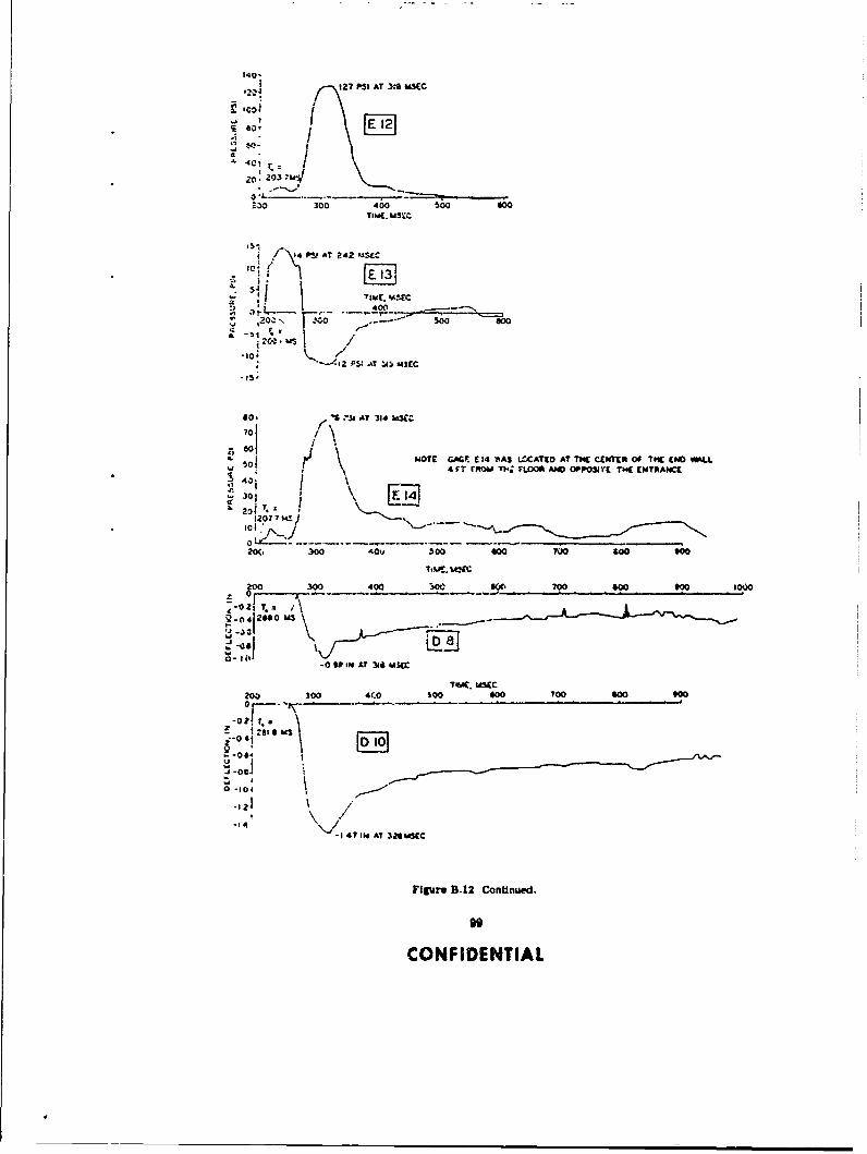
127 PSI AT 3* SEC14E12
.,o: ;03- /
: ,.0 3 o o; 4 0 0 S o0 o 0 0 0
" /P AT 242 P |C C
20, 300 000 500 s0G
-1 , r -;
TIM(.. ,5XC
4 f--- AT" U5 - "EC
E.l13B12Cn~ud
0O FI AT 1NTI
70~ ~
20 2
.1 If'
20. 300 aATIv 50 w ? "
3w 400 i ROM 400 90 00 tooS~i 1000~hN
-jI
20(. 300 400v Soo 000 __Too0 60
00 -10400
-1420 U141 A 24M
-Offr B-1 Co 344 US(
CONFIENTIAL
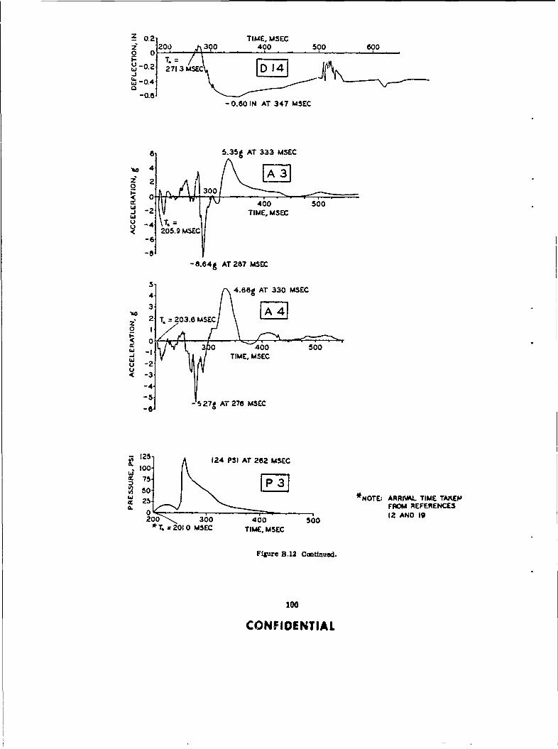
0.2 TIME, MSEC1200 h 300 400 500 600
2 0
27135 ATM33 EC0.2 3 -
j
LL o
- 0.4
0.60 IN AT 347 SEC
6 5.35g AT 333 MSEC
2
-6
0-30
'.r 460L p ,o 500
w
• J &/ TIME, MSECwU -4 T
U
-6
-8"-a.64g AT 287 MSE
4 4.68g AT 330 MSEC3
*10
cc 0- 300 '400 500
2 T T20, MSECEC0 I2
*( 0o
UU
-6 -527g AT 270 USEC
125. 124 PSI AT 262 MSEC~100.
75- [3___________________________*NOTE; ARRrL TIME TMKEPA
a.25 FROM REFERENCE3
0 30 i 12 AND 19*T. z 2010 MSEC TIME, MSEC
Figure B.12 CcutUnued.
100
CONFIDENTIAL

I ISO 19P31AT 232 WCC PI
140 GRADE10o 3
0
100~~ ~ 20 3040 .. . 40 T* 0, 0 0
~E 4
140 145 PSI AT 238 MW INSTRIMENT LOCATIONS, STRUCTURE 3.1 G
120 TNOTE: INMARD OFLECTIONS AND DOWNVA.
100 ACCELERAT00 ARE NEGATN
aoj j5 NO RECOPOS WERE MAIMED FROMso GAGES OZ, 04 0 , O rt. C3r.80 AND r7
40 GAGE P2 RECORDED 0 PS
0,T. a174 91 MS C'I . LEGEND
100 200 360 400 S00 P AIRt PRE33URETIME, LOW - EARTH PRESSUR
A - ACCELEATION0- DEFLECTION (ELECTRONIC)
00 200 300 490 590 O9 790 690
-02 T.244M
_ -04o-08
.- -Os-to
.:
F I I-4 S6IN AT 241 MMC
00 200 30 400 S" 700 or
2 T. 200.7 US
-0
-051 -1.29I N AT 242 MI
-ia. ,. aisa w
i a5 T*AL14UM~ 100 200 30
d -*ol-0*oIIN A? 77 ,m
FlIgure B.13 Traisnit rwora a earth pmsuemr, doncUim, acw erason, wMair overpre wu* for Str oture 3.1...
101
CONFIDENTIAL

a 5.a7g AT 285 MSEC4 T. 170.3 MSEC
2o 2 100 v2 300 400
.( -4 TIME, MSEC
U -8
101 0:751 AT 227 USEC
2A
2-14
- 1 41-13.37 g AT 2 17 MSEC
200' 1599 PSI AT 216 MSEC180
120~80~ * T - *NOTE: ARRIVAL TIME TAK~EN FROM40~ 183 MSEC I.EFERVtJCES 12 AND 190"100 200 360 400 500
TIME, MSEC
Figure B.13 Continued.
102
CONFIDENTIAL
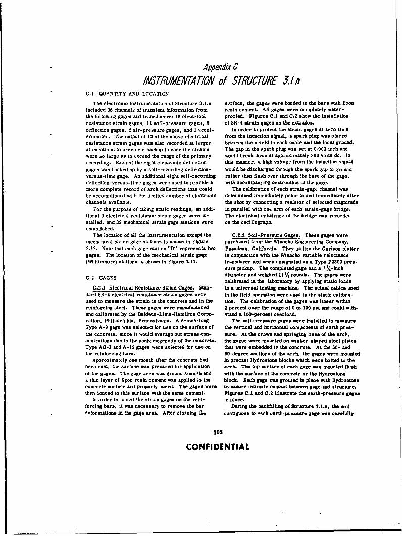
Appendix C
INSTRUMENTATION of STRUICTRE 3. nC.1 QUANTITY AND LCCATION
The electronic instrumentation of Structure 3.1.n srface. the gagea were bonded to the bars with Eponincluded 38 channels of transient information from resin cement. All gge, were completely water-the following gages and transducers: 16 electrical proofed. Figures C.1 and C.2 show the installationresistance strain gages, 11 soil-pressure gages, 8 of SR-4 strain gages on the extrados.deflection gages. 2 air-pressure gages, and I accel- In order to protect the etrain gages at zero timeerometer. The output of 12 of the ,ibove electrical from the Induction signal, a spark plug was placedresistance strain gages was also recorded at larger between the shield in each cable and the local ground.attenuations to provide a backup in case the strains The gap in the spark plug was set at 0.003 inch andwere so large Ps to exceed the range of the primary would break down at approximately 800 volts dc. Inrecording. Each )f the eight electronic deflection this manner, a high voltage from the induction signalgages was backed up by a self-recording deflection- would be discharged through the spark gap to groundversus-time gage. An additional eight self-recording rather than flash over through the base of the gage,deflection-vereus-time gages were used to provide a with accompanying destruction of the gage.more complete record of arch deflections than could The calibration of each strain-gage channel wasbe accomplished with the limited number of electronic determined immediately prior to and Immediately afterchannels availanle. the shot by connecting a resistor of selected magnitude
For the purpose of taking static readings, an addi- In parallel with one arm of each strain-gage bridge.tional 9 electrical resistance strain gages were in- The electrical unbaltnce of the bridge was recordedstalled, and 39 mechanical strain gage stations were on the oscillograph.established.
The location of all the instrumentation except the C.2.2 Soil-Pre.sure Gages. These gages weremechanical strain gage stations is shown in Figure purchased from the Wiacko Engineering Company,2.12. Note that each gage station "D" represents two Pasadena, Call'orrla. They utilize the Carlson plattergages. The location of the mechan;cal strain gage in conjunction with the Wlancko variable reluctance(Whittemore) stations Is shown in Figure 3.11. transducer and were designated as a Type P2303 pres-
sure pickup. The completed gage had a I '/4-inchC.9 GAGES diameter and weighed 11 4 pounds. The gages were
calibrated in the laboratory by applying static loadsC.2.1 Electrical Resistance Strain Gages. Stan- in a universal testing machine. The actual cables used
dard SR-4 electrical resistance strain gages were In the field operation were used In the static calibra-used to measure the strain In the concrete and in the tion. The calibration of the gages was linear withinreinforcing ateel. These gages were manufactured 2 percent over the range of 0 to 100 psi and could with-and calibrated by the Baldwin-Lima-Hamilton Corpo- VAtnd a 100-percent overload.ration, Philadelphia, Pennsylvania. A 6-inch-long The soil-pressure gages were installed to measureType A-9 gage was selected for use on the surface of the vertical and horizontal omponents of earth pres-the concrete, since It would average out stress con- sure. At the crown and springing lines of the arch,centrations due to the nonhomogeneity of the concrete, the gages were mounted on waser-shaped steel platesType AB-3 and A-12 gages were selected for use on that were embedded ir the concrete. At the 30- andthe reinforc:ng bars. 60-degree sections of the arch, the gages were mounted
Approximately one month after the concrete had In precast Hydrontone blocks which were bolted to thebeen cast, the surface was prepared for application arch. The top surface of each gage was mounted flushof the gages. The gage area was ground smocth and with the surface of the concrete or the Hydrostonea thin layer of Epon resin cement was applied io the block. each gage was grouted in place with Hydroatoneconcrete surface and properly cured. The gages were to assure intimate contact between gage and structure.then bonded to this surface with the ane cement. Figures C.1 and C.2 illustrate the earth-pressure gages
In order tn 'u.nt the strain g~ges on the rein- in place.forcing bars, it was necessary to remove the bar During the backfilling of Structure 3.1.n. the soil4oformationa In the gage area. After clcining ti ewiUguous to ,ach earthprur gag was carefully
103
CONFIDENTIAL
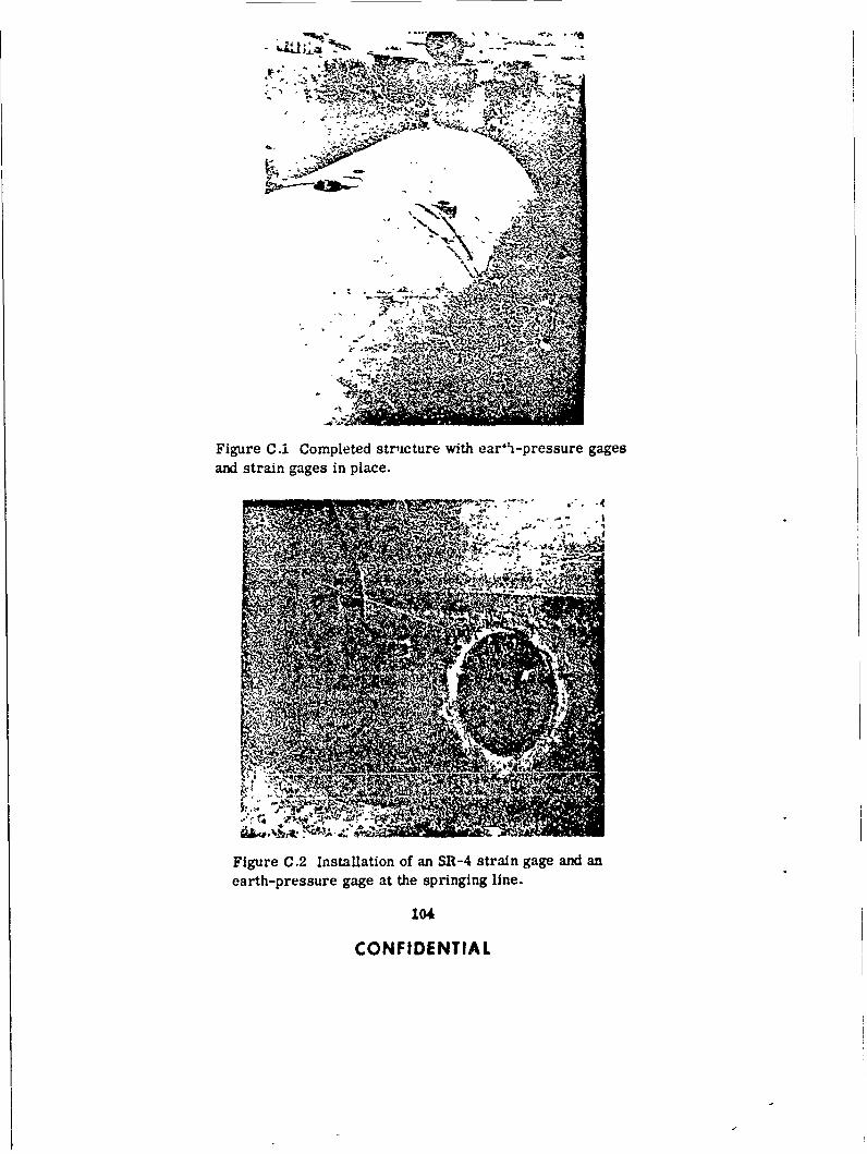
?
Figure C.1 Completed structure with ear~h-pressure gages
and strain gages in place.
4a44
Figure C.2 Installation of an SR-4 strain gage and an
earth-pressure gage at the springing line.
104
CONFIDENTIAL
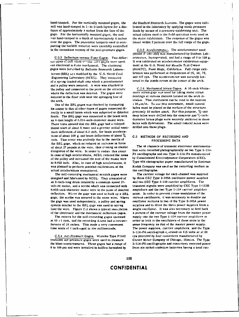
hand-tamped. For the vertically mounted gages, the the Stanford Research 1iotiute. The gages were call-soil was hand-tamped In 1- to 2-inch layers for a dis- brated in the laboratory by applying static pressuretance of approximately 4 inches from the face of the loads by means of a pressure-calibratng unit. Thegage. For the horizontally mounted gages, the soil actual cables used in the field operation were used inwas hand-tamped to a depth of approximately 6 inches the staitic calibration. The responbe of the gages wasover the gages. The pneumatic tampers used in corn- linear within 2 perccnt over the full range of the gage.pacring the backfill material were carefully controlledin the immeaiate vicinity of the soil-pressure gages. C.2.5 Acceleromete.'. The accelerometer used
(Model F-100-350) was manufactured by Statham Lab-C.2.3 Deflection-versus-Time Gages. Two differ- oratories. lncorpo'ated. and had a range of 0 to 100 g.• Ypes -;,' ,Cfl clin-v--Zu. ..: gnges were uatqt It wis calibrated on accelerometer calibration equip-
une electrical aid one mechanical. The electrical men: at the U.S. Naval Air Mi,,ile Tist Cnt,.rgages were fur-,N;,hed by Ballistic Research Labora- (NAMTC). Point Mugu. California. Full-range call-
tories (BRL) z..z: modified by the U.S. Naval Civil bration was performed at frequencies of 25, 50, 75.Engineering Laboratory (NCEL). They consi:,ted and 107 cps. The accelerom ter was securely fas-
of a spring-loaded shaft onto which a potentiometer tened to the inside crown at the center of the arch.
and a pulley were secured. A wire was attached tothe pulley and connected to the point on the structure C.2.6 Mechanical btrain Gages. A 10-inch Whitte-
where the deflection was desired. The gages were more strain gage w, as used for taking static strainsecured to the floor slab near the springing line of readings at various rtations located on the arch in-the arch. trados. This instrument can be read to the nearest
One of the BRL gages was checked by compAring 1 10 #mn/in. To use this instrument, small conical
Its output to that of other types of gages connected dl- holes must be placed in the surface of the stricture
rectiy to a small beam which was subjected to dynamic precisely 10 inches apart. For tius purpose. -inct
loads. The BSL gage was connected to the beam with deep holes were dri:led into the concrete and '/-inch-
an 4-ioot length of 0.024-inch-diameter music wire. diameter brass plugs were securely anchored in the:seThese tests showed that the BRL gage had a delayed holes with Hydrostone. The bmall conical nuics were
Initial start of about 5 msec and a greater initial maxi- drilled into these plugs.
mum deflection of about 0.2 inch, for beam accelera-tions of about 100 g and beam deflections of about 3/4 C.3 METHODS OF RECORDING ANDinch. This error was probably due to the inertia of PROCESSING DATAthe BRL gage, which int -oduced an increase in forceof about 27 pounds in the wire, thus c,-using an elastic The 48 channels of transient electronic instrumenta-
elongation of the wire. In order to reduc, this error tion were recorded photographically on two Type 5-114-
in case of high accelerations. NCEL reduced the mass P3 oscillographs and one Type 5-114-P4 manufacturedof the pulley and increased the size of the music wire by Consolidated Electrodynamic Corporation (CEC).to 0.033 Inch. Also, in case of high accelerations, it Type 809 ootographic paper manufactured by Eastmanwas planned to perform postshot calibrationb at the Kodak Company was ustd as the recording medium mactual acceleratiuns encountered. the oscillographs.
The seh:-recordNg mechanical scratch gages were The carrier voltage for each channel was supplieddesigned and fabricated by NCEL. They consisted of by three CEC Type 2-I05A oscillator-power buppliesan 8-inch-long drum rotated by a constant-speed 27- and two CEC Type 1-118 carrier amplifiers. Thevolt-dc motor, and a scribe which was connected with transient signals were amplified by CEC Type 1-113B0.033-inch-diameter music wire to the point of desired amplifiers and the two T)pe 1-118 carrier amplifierdeflection. WLzre the gage was used to back up a BRL units. In order to prevent cross-modulation of thegage, the Scribe was secured to the same wire. Where various oscillators. it was necessary to disable dethe gage was used independently, a pulley and spring oscillator sections in two of the Type 2-10f.A powersystem similar to the BRL gage was used to spring su.)plies and t) drive the three power supplies from aload the wire. Figure C.3 shows a typical insa.ilatlon sirg!e oscillator. It was also necessary to feed backof the electronic and the mecnanical deflection qages. a portion of the carrier voltage from the master power
The motors for the self-recording giges operated supply into the two Type 1-1 IR carrier amplificrs inat 60 t I rpm. and zhe recording d.ums had a circum- order to lock in the oscillators if these units to theference of 10 inches. This made a very convenient same frequency as that of the master power supply.time scale of I inch tqual to lou milliseconds. The power supplies, carrier amplifiers, and the Type
5-114-P4 oscillograph o, crated on 115 volts ac at 60C.2.4 Air-Pressure Gages. Wiancko Type P1412 cpa provided by four converters manufactured by
trani, ent air-pressure gages were used to measure Carter Motor Company of Chicago. Illinois. The T)pethe blast overpressures. These gages had a range of 5-114-P3 oscillographs and converters received power0 to 100 psi and were installed in baffles furnished by from six nickel-cadmium batteries having a total rat-
105
CONFIDENTIAL

ing of 360 ampere-hourzs .' !2I ,ultsi. graiphzs. All equipmewnt is ..!,- the instrunment shelterThe BR L dlik tion gaige [Ii iiigeb tttre opferated at was :securel) an, horeil to stork Lennehvs by means of
approximantely 6. 1 .,olo, tic fronti the nickcl-cadium bhtick-mj)uit cunflectionsb.
baitteriv.. Thv at tuA ltg atc~ .ic ht little ut, ip be Sifvc thu. u.'tpient tvuld -our be manuatiy operated
tilt!I. a tv I Int t ki ~I..I t titit sit t.it . .~. .iculiltttI III kotn du ring~ th ht t. At A - :It( bba: y to rely (in standard
,)I c ht- ,.,% illgi *ph- I fit !, ti, - -it Aavig. thaiie t Iinmig isgn i - *,i,' i it . i - ElIgvrton. (Jtrnmebihtuben
-%ccb. lant - it lIn In. .,tc. a C. :tcu. % M-1 1,41! ind (ii Iva j 6). A JU0-taiinute signal act.teated a
1ri*tgt t .uitruil tlliit *:caiu tak t it Iv Ckt u rl Lit vii 'n - stdtnuid u.nit ItI !, .. m .1 A.- .evy-duty knile switch,
iec. ind Itisti u nit nt, lilt ... ro A Dza. t Ik iahinia. ithe I iht 1iw"'idiig .. %%v i'., the :k %er bulipi es and os-
An cttio-i-hit.1 inw e,ilt -- .1 itit it iaUittui kil .I. rpli.- lit oi .i that the equipment tuuld be
(1) ri at 1,-r un .. ii tici , cti aunii. r, i. sntt d %% . . I ati. i L.;, 1) '.i % iit i'.t. ihib t-gnAl w ;is backed up
top thetic fitit:%:---h.rt: tit. * .... -) 'tt i-ping arius- 15-1tiinut. Ig~iiAI.stitches fit: t i.i i -a' .it tti...ni ~.~ i iiannh 1_'. At :iiufd, I., *.t- .n.. ai ,inal initiated a time-
andt! .1) tinwt -i. stiti , lot tI u.igtf ::. iga,/int dt, -,I~ a. .pinwiiiatelp 9 ,etitii. azt whiUctidrti e tit i tilt- *,-t iilgah ... .. h tinie thi. iiagait dhiit~z utsi thtub-osillugriphs uere
Figurte C 3 T~picai ifltallatioin of the e.lectronic anmi
the. nctch.utica deflect ion g:.tus
s hot cal ibrationi. aind tut ning Ill , qjuipitn fi.11. All started. Autoumatic stepping bwttches %%ere also
rtl~q%,; in the timt-tenc-,jl unit ttvr .. Ii thL nmet hanical started sihich lproid'ivd an clectrical signal for cali-
lach t~pe. hratiuin put pu.ses tip all atrain gage ci'annelb In se-
Tlie recurting instruimnt, Sit rt lit atkd in an under- qiencif. The l.st step of the stepp)itng switch supplied4round Instrument bhit Rtr .ip.. %tuui #)'1 ivet trom a signal whiah %as rvcorded on an extra channel onStructure 3. 1.... rht in,ti umt ft ,ht tt ; hadl rt inluirced- all u.~tiIiijgrjph-. rhas .lfirued a means of coordinat-, ncrvtt wAils Ind ruu -', am ice t~.it k. %wih tie ltp if ing the records l-oom tht. three oscillographs. A minuas-
the shelter it ground letel. An vas th miound -. prpm - S-second %ignail was .scd to back up the mirnus-15-macely 5 feet chick %%:,s plo ii ..%r the cter, second signlal.
It was ixsperted that the ni.timum :,utal radiation A minus-l2 %--uvound bignal was ustd to start theinside the' snvlter houuld it u. h than ripvt.tgut~. rotating tit ui, tit-it t tion gages. Thts signail alsoThis amount of raiain %wiu~ti i,ot produte vsignilicant started two tinhe-detlay motors. one to initiate thelegging ofi the Eastman Kodak r~ipe -409 paper Ahich postshot t alibration of all strain-gage channels and.as usi'ui is the re-or-ling coculium in the three usc Ill - one to %hut off the t ILettrical jpoiter to all equipment.
106
CONFIDENTIAL
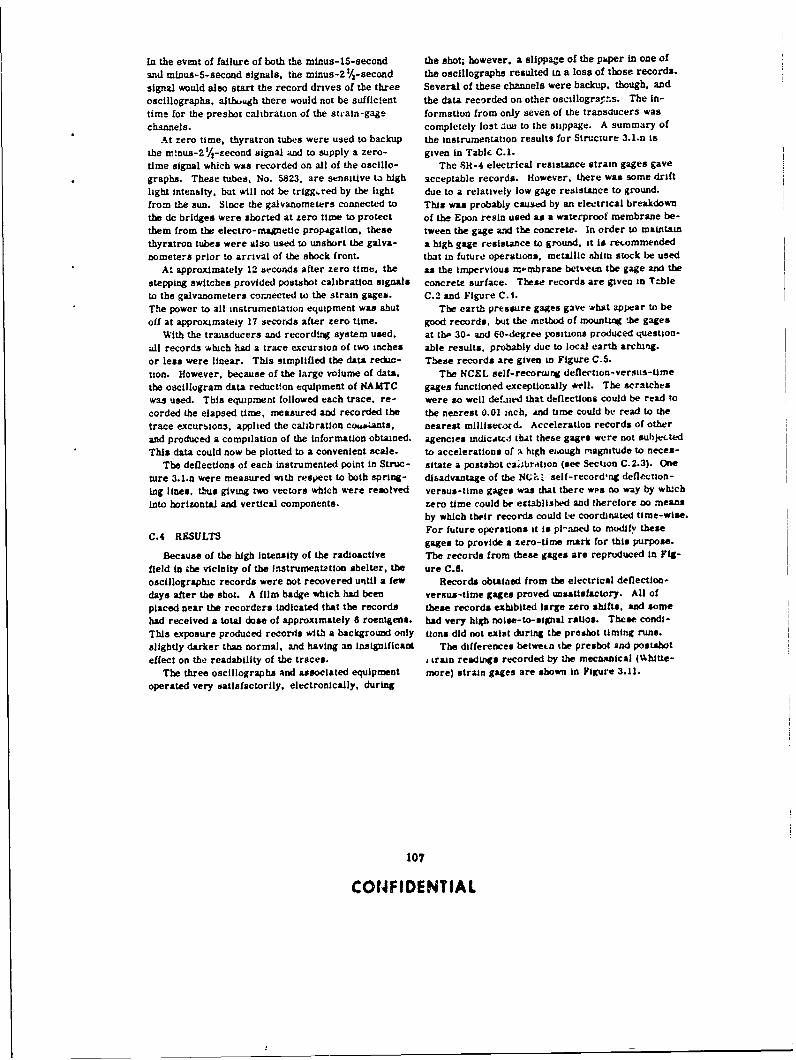
In the event of failure of both the minus-15-second the shot; however, a slippage of the puper in one of
and minus-5-second signals, the mlnus-2 %-second the osclllographs resulted in a loss of those records.
signal would also start the record drives of the three Several of these channels were backup, though, and
oscillographs. although there would not be sufficient the data recorded on other osclllograr s. The in-
time for the presot calibration of the strain-gage formation from only seven of the transducers was
channels, completely lost due to the slippage. A summary of
At zero time, thyratron tubes were used to backup the Instrumentation results for Structure 3.1.n is
the m'nus-2'/V-eecond signal and to supply a zero- given in Table C.I.time signal which was recorded on all of the oscillo- The Sl-4 electrical resistance strain gages gave
graphs. Theae tubes, No. 5823. are sensitive t3 high acceptable records. However, there was some drift
light intensity, but will not be triggered by the light due to a relatively low gage resistance to ground.
from the sun. Since the galvanometers connected to This was probably caused by an electrical breakdown
the dc bridges were shorted at zero time to protect of the Epon resin used as a waterproof membrane be-
them from the electro-magnetic propsgation. these tween the gage and the concrete. In order to maintain
thyratron tubes were also used to unshrt the galva- a high gage resistance to ground. it is recommended
nometers prior to arrival of the shock front. that in future operations, metallic shim stock be used
At approximately 12 seconds after zero time. the as the Impervious m,.mbrane between the gage and the
stepping switches provided postabot calibration signals concrete surface. These records are given in Tableto the galvanometers cornected to the strain gages. C.2 and Figure C.I.The power to all instrumentation equipment was shut The earth pressure gages gave -what appear to be
off at approximately 17 seconds after zero time. good records, but the method of mounting the gages
With the transducers and recording system used, at tbe 30- and 0-degree Fositions produced question-
all records which had a trace excursion of two inches able results, probably due to local earth arching.
or less were linear. This simplified the data reduc- These records are given in Figure C.5.uon. However, because of the large volume of data. The NCEL self-recorng deflection-versis-tme
the oscillogram data reduction equipment of NAMTC gages functioned exceptiorally *ell. The scratches
was used. This equipment followed each trace. re- were so well def.ned that deflections could be read to
corded the elapsed time, measured and recorded the the nearest 0.01 ,nch, AM time could be read to the
trace excurbion3, applied the calibration co,* ants, nearest millisecord. Acceleration records of other
and produced a compilation of the information obtained, agencies andicAt'C1 that these gages were not subjected
This data could now be plotted to a convenient scale. to accelerations of a high e.,ough magnitude to neces-
The deflections of each instrumented point in Struc- sitate a postahot casibrtion (see Section C.2.3). Oneture 3.1.n were measured with respect to both spring- disadvantage of the NC?.o self-recordng deflicuon-
Lag lines, thus giving two vectors which were resolved versus-time gages was that there wpa no way by wtuch
into horizontal and vertical components. zero time could be established and therelore no meansby which their records could Le coordinated time-wise.
C.4 RFSULTS For future operations it is pli ned to modify thesegages to provide a zero-time mark for this purpose.
Because of the high intensity of the radioactive The records from these gages are reproduced in Fig-
field in the vicinity of the Instrumentation shelter, the ure C.6.oscillographic records were not recovered until a few Records obtained from the electrical deflection-
days after the shot. A film badge which had been versus-time gages proved unsatisfactory. All of
placed near the recorders indicated that the records these records exhibited large zero shifts. and somehad received a total dose of approximately 6 roentgens. had very high noise-to-signal ratios. These condi-
This exposure produced records with a background only tions did not exist during the preshot timing runs.
slightly darker than normal, and having an Insignificant The differences betwetn athe preshot and postshot
effect on the readability of the traces. , train readings recorded by the mecanical (Uhitle-
The three oscillographs and associated equipment more) strain gages are shown in Figure 3.11.operated very satisfactorily, electronically, during
107
C014FIDENTIAL
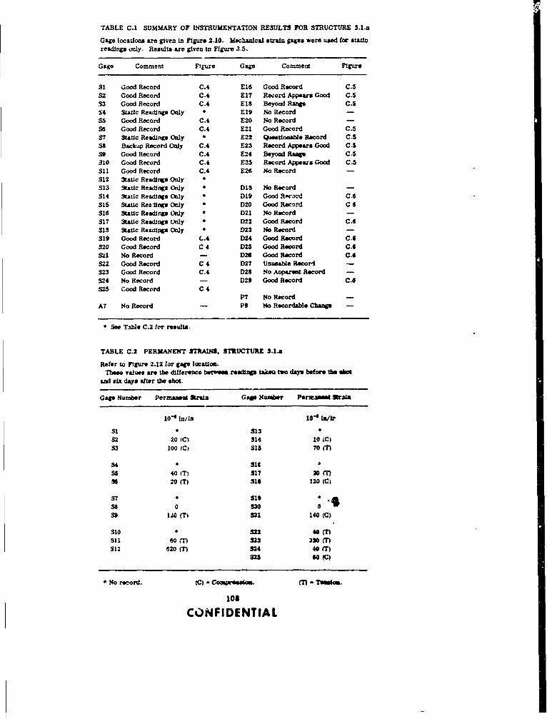
TABLE C.1 SUMMARY OF INSTRUMENTATION RESULTS FOR STRUCTURE 3.1.n
Gage locations are given in Figure 2.10. Mechanlcal strain gages were used for staoreadings only. Results are given in Figure 3.5.
Gage Comment FIEure Gage Commerl Figure
SI ;.ood Record C.4 E16 Good Record C.S32 Good Record C.4 E17 Reord Appears Good C.5.53 Good Record C.4 £18 Beyond Range C.5
S4 Static Readings Only " E19 No Record -
S5 Good Record C.4 E20 No Record -S6 Good Record C.4 E21 Good Record C.537 St-I Readings Only 0 E22 Questlona e Record C.538 Backzp Record Only C.4 E23 Record Appears Good C.539 Good Record C.4 E24 Beyoad RMg C.S310 Good Record C.4 E25 Record Appears Good C.5S11 Good Record C.4 E26 No Record -S12 Static Reading Only 0
S13 Static Readings Only 0 DIS No Record -
314 Sautic Readings OWJy D 019 Good Rpco.-d C.6315 Static Re,,fings Only D D20 Good Record C 6316 Static Readings Only * D21 No Record -
317 Static Readings Only * D22 Good Record C.6315 Static Readigs Only * D23 No Record -
319 Good Record (..4 DZ4 Good Record C.6320 Good Record C 4 D25 Good Record C.6S21 No Record - 26 Good Record C.6
322 Good Record C 4 D27 Unuasbe Record -
323 Good Record C.4 D28 No Aprest Record -
324 No Record - D29 Good Record C.6
S25 Cood Record C 4P7 No Record
A7 No Record - Ps No Recordable Cban -
See Table C.2 for results.
TABLE C.2 PERMANENT STRAIN. STRUCTURE 3.1.a
Refer to Figure 2.12 for gage locaito.These valuea are the difference betwem r Wdip takeo two days before the shot
and aIx days after the shot.
Gage Number Permanes Strain Gage Number PermAmt Strsa
10"4 n/tn 10
" ' lr
S1 3 313 0
32 20 IC) 314 10 (C)S3 lo (C) Sis 70(T)
54 s ic( a
S5 40 (T) S17 20 ()S2o 0(T) Sig 120 (C)
57 S19 0 .,380 S9120 (T) 821 140 (C)
S10 3 823 40 (")311 60 S23 30 "S12 620 (T) S24 40 (T)
* No record. (C) - Com.realom. (7) - Tlmsss.
108
CONFIDENTIAL
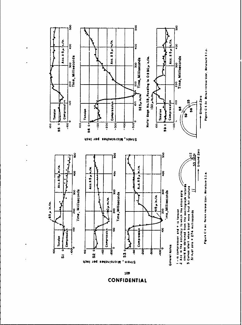
8V
d 0
4! 4
0
2 inA
od 0
CL GL
fa
2 20 .5
o 0 0 0 02 1 0 0
tou fed Ie uoi~ In T~
0
, 0. C
= a. 0
4*4 JSi IP -101 ; U2*
1100CONFIDENTIA

c ~ J
0 -
o 0 0 g o
0 0 0 0 oN in
43t'i jad sauioiV4qusojjS
00
J-~J-e0
- -'
r= EI
E E
c -g
-1 10c c
CON5D N(A L)

0 ~ 0
c c
00
c2
0
w u1
u
c -j' ~
-N N -w
00
A0t
woF,
N cN
00 cc oF8 00
000
40 fj
0 = 9 c
w ou~
N C45 45 455
Vul .!nSa pnd &nsJ 4O
III -
CONFIDENTIA

- .5-
6 -
00CC
3o0! 0I 00
,0 /
1 08
obo
N t N
o 4'
- 140 C14 3 cl IS00
0
112~I u4~a
CONIDETIA
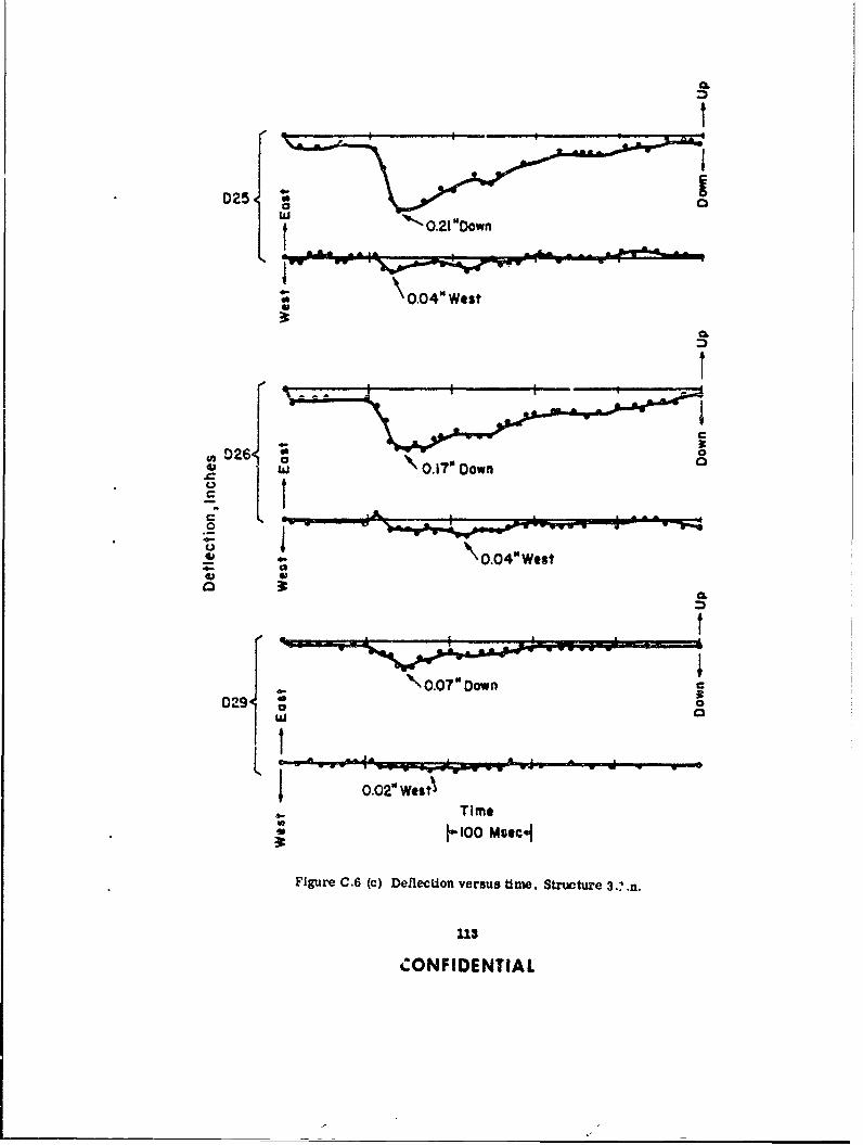
D2 *0.21 "Down
0.04" West
yD26{ o
o ~ 0.7 b4eV.~~Don r
\.04" Weat
\ 0.07" Down 0
L -6
0.02" WlstTime
h;00 Mmtcci
Figure C.6 (c) Deflection versus time, Structure 3'n
113
CONFIDENTIAL

Appendx 0'RADIATION INSTRUMENTATION
D.1 BACKGROUND AND THEORY
Tests prior to Operation Teapot have shown that emulsion energy response, which has peaks near thebelow-grade shelters give 75 percent better gamma K-shell photoelectric absorption edges, absorber andsaieldng than those shelters that are partially above bromine, by placing the entire emulsion in an 8.25-rsade (Reference 20). Teapot data illustrated that mm-thick oakelitt case covered with 1.07 mm of tin
completely below-grade shelters with 4 feet of verti- and 0.3 mm of lead and surrounded by a 1/%-inch leadcal earth cover gave an inbide-to-outslde gamma-dose strip over the oi-*n edges. The entire arrangementratio (to be defined herein as a gamma transmission is placed in a p.astic cigarette case.factor) as low as 1.2 x 10- and a neutron transmission Although the angular dependence of the gamma filmfactor of 1.4 x 10⁻⁴ for the high-energy neutron flux packet when it Is exposed to higher energy radiation iswhich would be detected by sulfur threshold detectors negligible, for lower energies it is important. An in-(Reference 21). Detector stations nearer to the en- terpretation of the results obtained by Ehrlich (Refer-tranceways of the structures indicated much greater ene.i 24) indicates that. for radiation isotropically in-transmission factors and therefore received higher cider. on the packet, the dose value is about 5.5 percentradiation dosages. lower for 1.2-Mev radiation than that obtained by an
The shelters to be instrumented for radiation mesa- tnstrumi.t having no angular dependence, about 32 per-urements during Operation Plumbbob were all under- cent low for 0.20-Mev radiation, and about 45 percentground. For this reason, the Teapot results in low for 0.11-Mev radiation. Although the film packetsbelow-grade structures UK 3.8A. UK 3.88, UK 3.8C, may show only 2 20-percent error in normal radiationand UK 3.7 were particularly useful in predicting ex- fields, some consideration should he given to the factpected shielding by the shelters during Plumbbob that in a relatively isotropic and degraded energy field,(Reference 21). These results were augmented by such as might exist in structures with many feet ofempirical relations for neutron and gamma radiation earth cover, the film packets may indicate low values.passing through hollow cylinders a' given in the "Re-actor Shielding Design Manual" for evaluating the ef- D.2.2 Chemical Dosimeters. The chemical dosim-fect of various openings and baffles (Reference 22). eters utilized for instrumenting the structures were
As a result of these analyses the only part of the supplied by the United States Air Force School of Avia-Plumbbob 3.1 structures expected to have an adverse tion Medicine (SAM).effect on shieldiig property was the entranceway. In The SAPA chemical dosimeters Include two mainregard to relative radiation dosages within such shel- types of chemical systems.ters, a consideration of the slant thickness (the line The measurement of the neutron dose with the high-of sight cover) would indicate that the greater dose I hydrogen-content dosimeter was accomplished by eval-to be expected in the portion of the shelter farthest uation of the amount of stable acid produced in a mixedfrom ground zero. radiation field by one of the above techniques. Since
the water-equivalent, high-hydrogen-content dosimeter
Is X- and gamma-ray energy-dependent and has a
D.2.1 Gamma Film Packets. Gamma dose was known neutron response, the total acid production can
measured with the National Bureau of Standards- be considered as a combined function of the neutron
Evans Signal Laboratory (NBS-ESL) film packets and gamma radiations. Subtraction of the gamma-
(References 23, 24. and 25). In the exposure range produced acids as measured by the fast neutron in-
from I to 50.000 r and in the energy range from 115 sensitive chemical dosimeter systems (Reference 26)
kev to 10 Mev the accuracy of the dosimeter is con- left a given quantity of acid produced by the neutron*.sidered to be within ± 20 percent. The net photographic Division of this neutron-produced acid by the acidresponse is expected to be approximately energy inde- yield per rep yielded a neutron dose in terms of reps.pendent. This is achieved by modifying the bare- Gamma measurements In the presence of neutrons
were accomplished by using the hydrogen-free dosim-
Prepared by Project 2.4. Radiological Division, eters. Since all chemical dosimeters are sensitive to
U.S. Army Chemical Warfare Laboratories, Robert thermal neutrons the thermal neutron dose was cal-
C. Tompkins. Project Officer. culated independently from cadmium-gold difference
114
CONFIDENTIAL
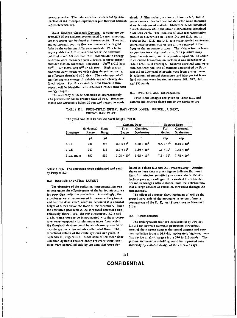
measurements. The data were then corrected by sub- sired. A film packet, a themic-l dosimeter, and intraction of 6.7 roentgen equivalents per thermal neutron wime cases it thermal neutron detector were installedrep (Reference 27). at each instrument station. Structure 3.1.n contained
6 such stations while the other 3 structures containedD.2.3 Neutron Threshold Devices. A complete de- 3 stations each. The location of ea h instrumentation
scriltion of the neutron system used for instrumenting station is referenced in Tables D.1 .ind D.3. and inthe structures can be found in Reference 2t. Thermal Figures D.1. D.2. and D.3. to a right-handed cartesianand epitherial neut.on flux was measured with gold coordinate system with origin at the centroid of thefoils by the cadmium difference method. This tech- floor of the structure proper. The X direction is Lakenniue yields the flux of neutrons below the ecdmium as positive toward ground zero, Y is posiuve awaycutoff of about 0.3 electron olt Intermediate energy from the entrance, and Z is positive upward. In orderneutrons were measured with ai series of three boron- to calculate tra,;SW.ission factors it was necessary toshielded fission-threshold detectors-PuUii (>:.7 kev). obtain free-field readings. Neutron spectral data wereNp' (-0.7 Mev). and U2 3 (>1.5 Mev). High energy obtained from the line of stations establisled by Pro-neutrons wer, measured with sulfur detectors havi-g ject 2.3 at 100-yard intervals west from ground zero.an effective threshold of 3 Mev. The cadmium cutoff In addition, chemical dosimeter and film packet free-and the various energy thresholds are not clearly de- field stations were located at ranges 287. 347. 383.fined points. For this reason neutron fluxes in this and 453 yards.report w.il be identified with detectors rather than withenergy ranges.
The accuracy of these detectors is approxmmately
± 15 percent for doses greater than 25 rep. Measure- Free-field dosages are given in Table D.. and
ments are unreliable below 25 rep and cannot be made gamma and neutron doses inside the shelters are
TABLE D.1 FREE-FIELD INITIAL RADIATION DOSES: PRISCILLA SHOT,FRENCHMAN FLAT
The yield was 36.6 kt and the burst height, 700 ft.
Gamma Dose Neutron DoseHorizontal Slant Film Chemical Foil Chemcal
Structure Range Range Badge Dosimeter Method Dosimeter
yd yd r r rep rep
3.1 c 287 370 3.0 x 101 3.00 x 10' 2.5 x 101 2.49 x 10'
3.1.b 347 418 2.0 x 10' 1.89 - 101 1.6 • 101 1.62 - 10s
3.1.a and n 453 510 1.05 x 101 1.02 x 10' 7.5, 10' 7 65 x 10'
below 5 rep. The detectors were calibrated and read listed in Tables D.2 and D.3. respectively. Results
by Project 2.3. shown as less than a given figure indicate the lowerlimit for detector sensitivity in cases where the de-
D.3 INSTRUMENTATION LAYOUT tectors gave no readings. It is evident from the de-crease in dosages with distance from the entranceway
The objective of the radiation instrumentation was that a large amount of radiation streamed through theto determine the effectiveness of the buried structures entranceway.for providing radiation protection. Accordingly, the The effect of greater slant thickness of soil on thestructures were Instrumented to measure the gamma ground zero side of the structure is evident from aand neutron dose which would be received at a nominal comparison of the D, E, and F positions in Structureheight of 3 feet above the floor of the structure. Since 3.ln.the activities produced in the threshold detectors arerelatively short-lived, the two structures, 3.1.a and.I.b. which were to be instrumented with these detec- D.5 CONCLUSIONS
tors were equipped with aluminum tubes from which The underground shelters constructed by Projectthe threshold devices could be withdrawn by means of 3.1 did not provide adequate protection throughouta cable systerr a few minutes after shot time. The most of their areas against the initial gamma and neu-structural details of the cable systems are given in tron radiation from a 36.6-kt. moderately high-neutror-Appendix G. Figure G.3. Since none of the other dose flux device at slant ranges from 370 to 510 yards. Thedetection systems require early recovery their loca- gamma and neutron shielding could be Improved con-tions were controlled only by the data that were de- siderably by suitable design of the entranceways.
115
CONFIDENTIAL
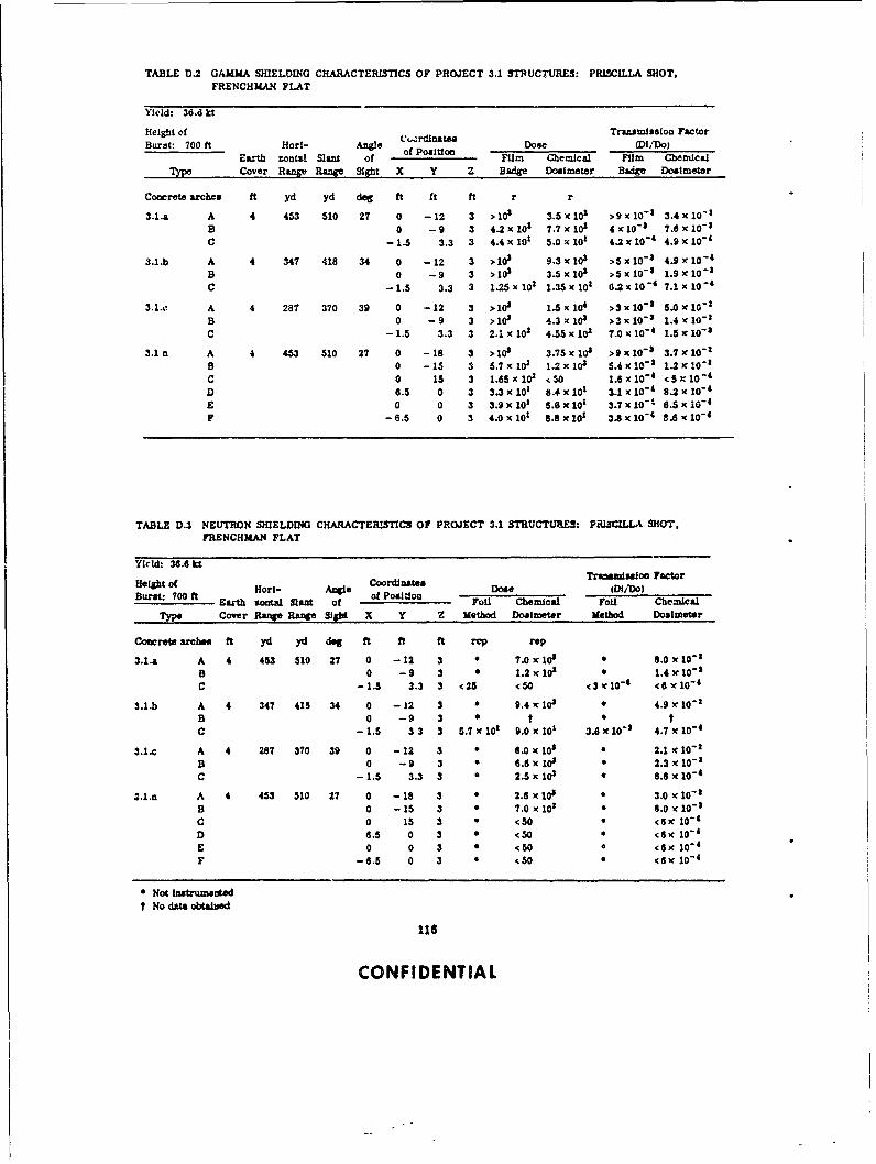
TABLE D.2 GAMMA SHIELDING CHARACTERISTICS OF PROJECT 3.1 STRUCTURES: PRISCILLA SHOT,FRENCHMAN FLAT
Yield: 36.6 kt
Height of .,rdinat" Transmission FactorBurst: 700 ft Horl- Angle of Poston Dose ChicFl C
Earth zonuW Sant of Film the-acai Film chmical
Type Cover Range Range Sight X Y Z Badge Dosimeter Badge Dosimeter
Concrete arches ft yd yd dog ft ft ft r r
3.1.a A 4 453 510 27 0 -12 3 >10' 3.5 x 10; >9x10 - 1 3.4 x 10⁻¹B 0 -9 3 4.2 x 101 7.7 x 10z 4,c 10
"' 7.6 x 10- '
C -1.5 3.3 3 4.4x 101 5.0xl10 4.2x10- ' 4.9x10
-
3.1.b A 4 347 418 34 0 -12 3 >10' 9.3 x 10³ >5x10 - 3 4.9 x 10 - 4
B 0 -9 3 >103 3.5 x 10³ >5 x 10- ' 1.9 x 10"1C -1.5 3.3 3 1.25 x 101 1.35 x 101 6.2 x 10"
4 7.1 x 10" 4
3.1.o. A 4 287 370 39 0 -12 3 >101 1.5 x 10
4 >3x10 - 5.0 , 10-
'B 0 -9 3 >10 4.3 x 10³ >3x10 -
3 1.4 x 10⁻¹
C - 1.5 3.3 3 2.1 x 10² 4.55 x 101 7.0 x 10⁻⁴ 1.5 x 10- $
3.1 n A 4 453 510 27 0 -18 3 >i08 3.75 x 10³ >9x10- 3 3.7 x 10"
B 0 -15 3 5.7x 10; 1.2 x 10 5.4x10 - ' 1.2)c10"C 0 15 3 1.85x101 .50 1.6x10 - 4
<53x10"1
D 6.5 0 3 3.3 x 10 1 8.4 x 101 3.1 x 10- 4
8.2 x 10- 'E 0 0 3 3.9 x 10 1 6.6 x 101 3.7 x 10
"' 6.5 x 10⁻⁴
F -6.5 0 3 4.0 x 101 8.8 x 101 3.8 x 10"t 8.8 x 10 - 4
TABLE D.3 NEUTRON SHIELDING CHARACTERISTICS OF PROJECT 3.1 STRUCTURES: PRISCILLA SHOT,FRENCHMAN FLAT
Yield: 36.6 ktTrmanloe Fector
Height of Coordinates anmsi FcoeitOLHot/- Angie Dose (01/Do)
Burst: 700 ft Hr- Age of Poaltioa oe /Earth sota Slant of f Psto Foil Chemical Foil Chemical
Type Cover Range Rae Slo X Y Z Method Dosimeter Method Dosimeter
Concret areh" ft yd yd dog ft ft ft rep rep
3,1.a A 4 453 510 27 0 -12 3 * 7.0 x 10 * 8.0 x 10"1
B 0 -9 3 * 1.2 x 101 0 1.4 V 10-1C -1.5 3.3 3 <25 <50 <3'x10- < 6x10⁻⁴
3.1.b A 4 347 418 34 0 -12 3 * 9.4'c I10 4.9 r 10" 1B 0 -9 3 t * tC -1.5 33 3 5.7 x 10² 9.0 x 10
1 3.6 x 10-' 4.7 X 10
-4
3.1.c A 4 287 370 39 0 -12 3 * 6.0 x 10S 0 2.1 x 10-B 0 -9 3 * 6.6 x 10 0 2.3 c 10- 1C -1.5 3.3 3 a 2.5 x 10; 0 8.6 x 10
- 4
.l.n A 4 453 510 27 0 -18 S * 2.6 x 10 3.0 x 10⁻⁸B 0 -15 3 * 7.0 x 103 0 8.0 x 10
-1
C 0 15 3 * <50 * <6c 10-4
D 6.5 0 3 * <SO c6 10-4
E 0 0 3 < < e <6c104
F -6.5 0 3 • <SO * <6x 10- 4
Not instrumentedt No data obtained
116
CONFIDENTIAL
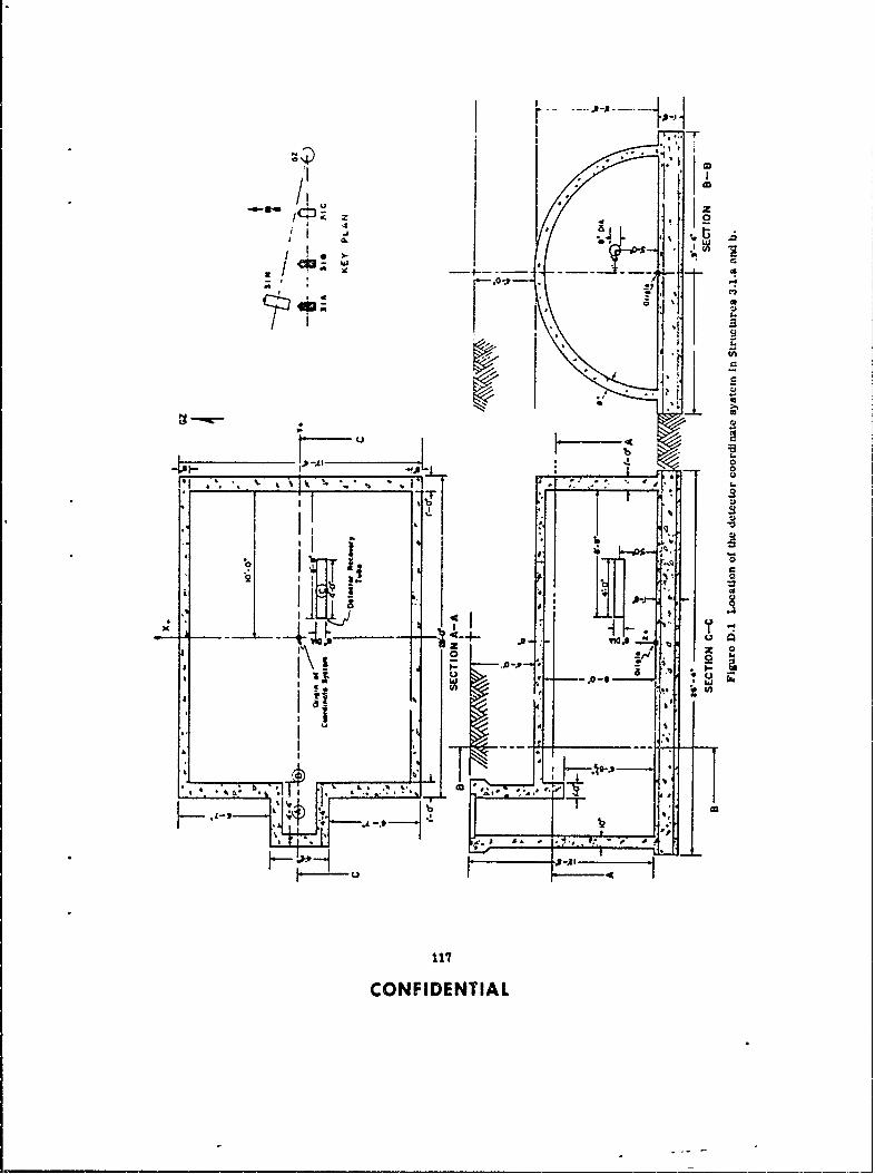
, I *11 ,
.. 4-u~ 10 i 0I
4 44
CIS
I Q ' z a
1171
CONFIDE qT{
II, a
" -I-.. ; -
10"
F-- *5
H- u -
117 r-CONFIDE NT IA

f I
/1 I II*. "-' z , ! i
, I II 4
I *-. PI I -
'I- --o----• -
1 D U
I S
F 5
CONFIENTIA

III
*
1I
"- ° ' *=1I [1.:;"~. i /ISi 0
i I
' S.4.
.Se
-. I 0
'
( ' ,
-.
A'
l.l I
' ,i , :
-- ., , - -4 1 lJ _ I
119CONFIDENTIAL
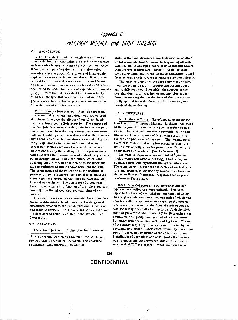
A4ppenda E'
INTERIOR MISSILE 01d OUST HAZARDE.1 B1ACKGROLND
E.1.1 Missile Hatard. Although most of th- re- traps in the four structures was to deter,nine whethercent work June in *uund ballistic s has bt en ci)ncerned or nut a missile hazard tconcrete fragments) actuallywith misbiles having %lu. itics b# tsv,, n 600 ind 9.000 existed. and to attempt a correlation uf missile hazardft/sec. it is also a fact that rel.ttively slow %elucit) with percent of structural damage. At the presentmissiles which are eecundar) flicts uf large-scale time there txists no precise assay of casualties causedexplosions cause signific.ant .asualties. It is an im- frm missiles with respect to missile size and velocity.portant fact that missiles with vc!ocities well below The main objtcti %s of the dust study were to docu-500 ft 'sec. in some instances even less than 90 ft/sec. ment the particle bizes if preshot and postshot dubtpenetrated the abdominal walls of tcperimental animals and to difffrentiate, if iossible. the sources of toe(dougs). From this. it is evident that slow-velocity posthhot dust. e.g.. whether or not particles arosemissiles, the type that would be exp~ected in under- from the existing dirt on the floor of shelters or ac-ground concrete structures. p0ssLs wounding capa- tually spalled from the floor. walls, or ceiling as abithUes. (See also Heierence 29.) result of the explosion.
E.1.2 Interior Dust Hazard. Fata!ities from the E.3 PROCEDURESinhalation of dust among individuals who had enteredstructures to escape the effects of aerial bombard- E.3.1 Missile Traps. Styrofoam 22 (made by thement are described in Reference 30. The sources of 1kw Chemical Company. Midland. Michigan) has mostthe dust (which often was in the particle size range to of the required properties of a good absorber of mis-mechanically occlude the respiratory pas.ages) were siles. The relatively low shear strength .nd the non-collapseJ buildings and the ceilings and walls of struc- fibrous cellular structure of St% rofoam result in lo-tures near which bomb detonations occurred. Appar- calized compressive defoimation. The resistance ofently, explusions can cause dust unside of non- Styrofoam to deformation is low enough so that rela-penetrated shelters not only because of mechanical lively slow velocity missiles penetrate sufficiently tofactors but also by the spalling effect, a phenomenon be measured accurately. (See Reference 29)_which involves the transmission of a shock or pressure The missile traps were constructed of '
/ 4-inch-pulse through the walls of a structure. which upon thick plywood and were 3 feet long. 1 foot wide. andreaching the air-structure inte-face at the inner sur- 11 inches deep with Styrofoam filling the entire box.face is reflected as tension wave back into the wall. The traps were located near the center of each struc-The consequence of the reflection is the spallirg of lure and secured to the floor by means of a chain an-portions of the wall and/or fine particles of different chored to Ramset fasteners. A typical trap in placesizes which are kicked off the inner surface into the is shown in Figure 2.14.internal atmosphere. The existence of a potentialhazard to occupants is a function of particle size. con- E.3.2 Dust Collectors. Two sonrwhat similarcentration in the inhaled a,r. and total time of ex- types of dust collectors were utilized. The firat.posure, taped to the floor of each shelter, consisted of an or-
Since dust is a known environmental hazard ana be- dinary glass microscopic slide, one inch of which wascause no data exist referable to closed underground covered with transparent scotch tape, sticky side up.structures exposed to nuclear detonations, a decision The second, cemented to the floor of each structure,was made to carry out field investigation to determine was the sticky-tray fallout collector: a ./s-inch-thick
if a dust hazard actually existed in the structures of plate of gatvan.zed sheet metal 9 1/ by 10 1/ inches wasProject 3.1. employed for rtgidity, on top of which a transparent
but sticky3 paper was fixed with masking tape. The topE.2 OBJECTIVES of the sticky tray (8 by 9 nchez) was pro.sctcd by two
The rtai object ive of placing Styrofoam missile rectangular pieces of paper which ordinarily are strip-ped off just before exposure of the collector. Upon
'This appendix written by Clayton S. White, M.D., installation of each plate one of the protective papers
Project 33.2, Director of Research, The Lovelace was removed and the uncovered side of the collectorFoundation, Albuquerque, New Mexico. was marked "C" for control. When the structures
120
CONFIDENTIAL

were closed up, the other protective osper was re- E.4 2 Dust Collectors. At the time of initial re-
moved. thus exposing the other side of the collector covery, the tops of the m'croscoplc slides were coy-marked "E" for experimental. ered with transparent scotch tape The fallout trays.
Thus the microscopic slides collected preshot and after being pried loose from the roor. were placedpostshot dust. the control side of the Wldlout collector face to fare,. care being tAken to opxose the con:rol
col!ected preshot and postsbot dust. anti the expert- side f one collector to the control side of the othermental side collected predominantly postsbot dirt. taken from the same shelter. These measures
Two sldes and two trays were placed in each struc- served to protect each of the dust collectors fromture. At the time oi installation of the slides and trays. contamnation after removal from the several struc-
z sample of dirt was scraped from the floor of each tures.structure and plced in a marked bottle. After recovery, the two opposing sheets of the
transparent sticky paper were stripped from the fall-
£.4 RESULTS otg trays. Inspection of the preparations revealedthe folloviirg: The sticky paper front all of the shel-
The structures were closed up two days before the ters was successful In trapping debris, particle sizesshot. at which time the protective covers were re- varied from microscopic particles of dust to discretemoved from the various missile traps. At the same pieces of mortar, wood. and small aggregates of dirt
time. the protective paper covering the experimental None of the material on the slides was identified .jside of the dust collector trays was removed. The orI6*inatng from the interior surface of the arch. Thestructures were initially re-entered four days after dust particles on the slides matched the preshot dustthe shot, at which time the slides and trays were re- samples taken from the floor of the structure
movea and returned to the laboratory for ailysis.E.5 CONCLUSIONS
E.4.1 Missile Traps. No evidence of concrete
fragments (missiles) were found in the missile traps E.5.1 Missile aiard The four concrete under-
or on the floors of the various structures. There wan ground structureb were free from concrete missiles.
one insignificart !xception. however. Prior to the No interior missile hazard existed in the structures
shot, a small bole in the end wall of Structure 3.1.c from the effects of a device of the yield tested in the
was patched with grout. The %all suffered some dam- Priscilla event beycad a range of 860 feet from ground
age from the detonation in the form of cracks, one of zero.
whirh passed through the grout po.ket. thus shakingloose some grout mterial. The cracked loose grout E5.2 Dust Hazard. It appears that no dust hazird
can be seen in Figure 3.21. was present an any of the structures.
121
CONFIDENTIAL
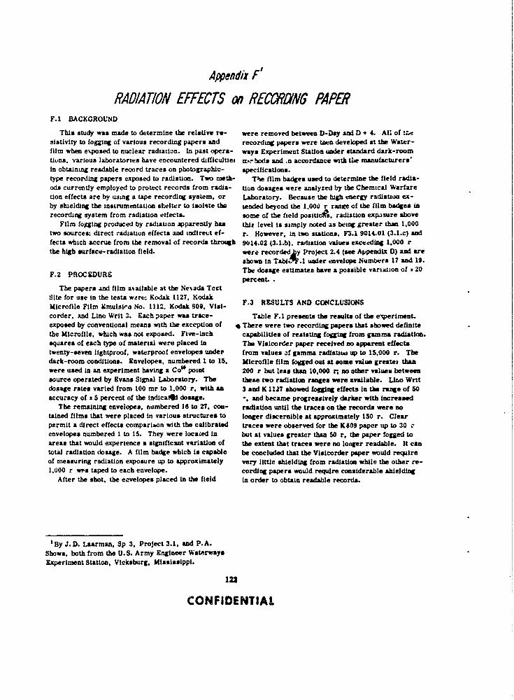
Appendix F'
RADIATION EFFECTS cn RECY2NG PAPERF.1 BACKGROUND
This study was made to determine the relative re- were removed between D-Day and D + 4. All of !mt-
sistivity to fogging of various recording papers and recording papers were ten developed at the Water-film when e',posed to nuclear radiation. In past opera- ways Experiment Station under standard dark-roomtulns. various laboratories have encountered difficultlet M%-bods and .n accordance with tia manufacturers'In obtaining readable record traces on photographic- speciflcations.type recording papers exposed to radiation. Two meth- The film badges used to determine the field radla-ods currently employed to protect records from radla- U= dosages were analyzed by the Chemical Warfaretion effects are by using a tape recording system, or Laboratory. Because the high energy radiation ex-by shielding the instrumentation shelter to isolite tho tended beyond the 1.00O r rane of the film badges inrecording system from radiation eifects. some of the field positie. radiation exp-sure above
Film fogging produced by radiation apparently has this level is simply noted as being greater than 1,000two sources: direct radiation effects and indirect ef- r. However, in two stations. F3.1 9014.01 (3.1.c) andfects which accrue from the removal of records through 9014.02 (3.l.b). raditlon -values exceeding 1.000 rthe high surface-radlation field, were recordedky Project 2.4 (see Appendix D) and are
shown in TabdC'F.1 under envelope Numbers 17 and 19.
F.2 PROCEDURE The dosage estimates have a possible variation of 1 20percent..
The papers And film m~ailable at the Neiada TeetSite for use in the tests wre. Kodak 1127. KodakMicrofile Film Ernwlsirl No. 1112, Kodak 809. Vlsi-corder. and Lino Writ 3. Each paper was trace- Table F.I presents the results of the e'qerimat.exposed by conventional means with the exception of , There were two recording papers that showed definitethe Microille, which was not exposed. Five-inch capabilities of resisting fogging from gamma radiatin.squares of each type of material were placed in The Visicorder paper received no apparent effectstwenty-seven lightproof. waterproof envelopes under from values of gamma radiauti up to 15.000 r. Thedark-room conditions. Envelopes, numbered I to 15, Microflle film fogged out at some value greatek thanwere used in an experiment having a Coo point 200 r but less than 10,000 r. no other values betweensource operated by Evans Signal Laboratory. The these two radiation ranges were available. Liao Writdosage rates varied from 100 mr to 1.000 r, with an 3 and K 1127 showed fogging effects in the range of 50accuracy of a 5 percent of the indicaMl dosage. -. ad became progressively darker with increased
The remaining envelopes, numbered 18 to 27, cowt- radiation until the traces on the records were notalned films that were placed in various structures to longer discernible at approximately 150 r. Clearpermit a direct effects comparion with the calibrated traces were observed for the KS0 paper up to 30envelopes numbered I to 15. They were located in but at values greater than 50 r, the paper fogged toareas that would experience a significant variation of the extent that traces were no longer readable. It cantotal radiation dosage. A film badge which is capable be concluded that the Visicorder paper would requireof measuring radiation exposure up to approximately very little shielding from radiation while the other re-1.000 r wrs taped to each envelope, cording papers would require considerable shielding
After the shot, the eavelopes placed in the field in order to obtain readable records.
By J.D. Laarman, Sp 3. Project 3.1, and P.A.Shows, both from the U.S. Army Engineer WaterwaysExperiment Staton, Vicksburg, Mississippi.
122
CONFIDENTIAL
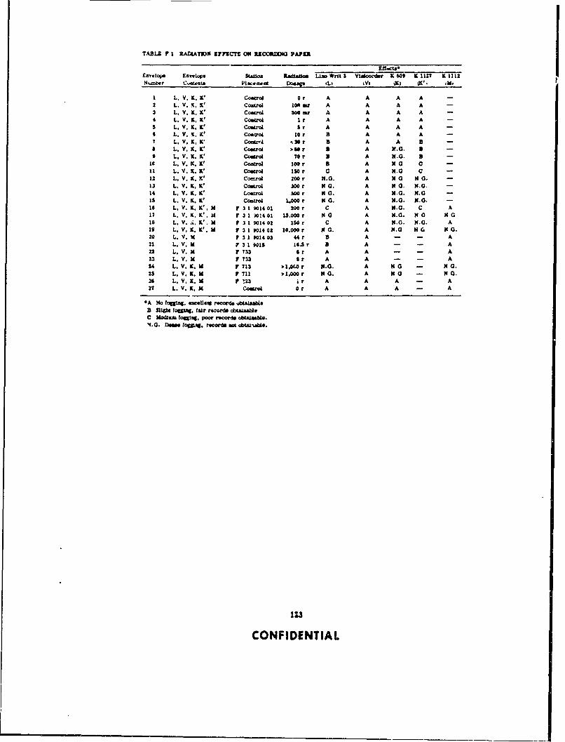
TABLE F 1 RADLATh31N rF fCTZ O JtZCCRD10 PAPIR
rai.cus£relope £avlcpa Station Rad"a0o Lao WrS oit $ or KIO KIM? K1112N4,mber C-atens 2Iaceawat Ro..q (L tyI %X (K' Mo
I L. V. K.K ' Costrol Or A A A A2 L.V. .K' contro 1mr A A A A3 L, Y. X. K' Conrol 1 ms" A A A A4 L. V. K, K' Contol I r A A A A$ L.V. K, V Contr Sr A A A A6 L. V. K. K Control IQ r B A A A7 L. V. K.K Contr1 30 r B A A B -
S L. V. K. K' Cord ,ut A N.G. a9 L, V. K. K' Cl r a A N.G. B -
19 L. V. K. X#
Cotrao 100 r B A NO C -11 L. V. K. K' como 15 r C A M.G C12 L. V. g. K' Cotrol 200 r W.0. A N 0 14 0.13 L.V. K, K' Control 30O r N 0. A N. .N.G.14 L. V. K. K' L l 50C r 0. A 34.G. N.G -
is L V. K. K' Control C00 r 3g0. A M4.0. X.0.16 L. V. K. K'. M 7 3 1 9014 01 200 r C A N.0. C A17 L.V. K. K'. X 3 1 3041 51.000 r N 0 A N.0. N 0 N G18 L V... . W. M' F 3 1 01402 150 r C A 3.0. N.0. A19 L. V. K. W. M 7 3 1 014 02 10.000 r go. A 3.G N p G.20 LV. V 7 3 1 901403 44r B A - - A21 L. V. M 3 1 901S 1. r B A - - A22 L. V. M 7 733 *r A A - - A23 L. V. M 7 733 8r A A - - A24 L.V.K. M 7 713 )-1.O r N.0. A N4 - NO.2. L, V. K, M 7711 0 1.00 r w 0. A 3 a - 340.2 L. V. K. M p i23 i r A A A - A21 L. V. K. M Corol 0 r A A A - A
*A No fniaag. mUeMlse records "laableB Sl5M Iolatn .fair records obtalaWeC MNa.ilm to n4h poo" records obtaal.'4.0. Dam fog .q. records ubtiaa.
1C3
CONFIDENTIAL
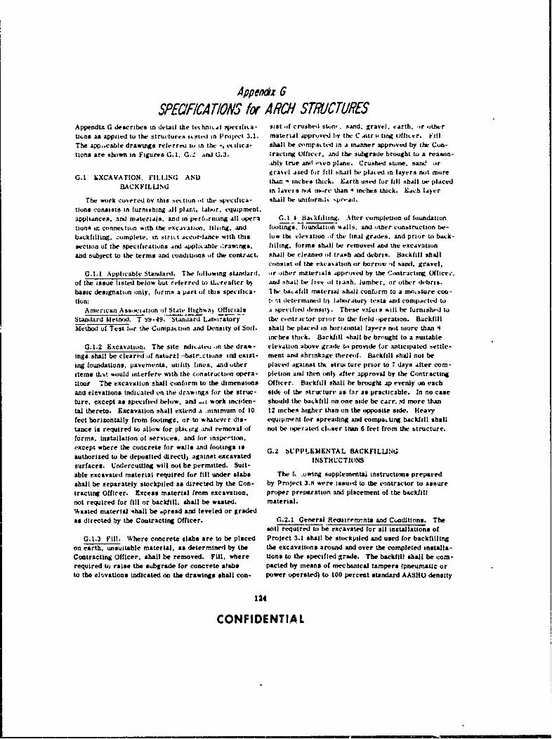
A4poerndz 6SPEe7FICATIONS fc RC/I STMUCTURES
Appendixt G describes tn detail the tethnio.Ai -Vieciliia- sift of crushed aton. . sAnd. gravel. earth. -or othertiu-ss as applied to the structures it 51.-U in Prioject 3.1. material approved byv the C ntr 44 ting Whfcrr. f~ill
The app.acabie drawings relerreti tv in the -, etilica- shall be ci-tipat ted ini A ibnner approved by the Con-tions are shown in Figures G.1. G._' tnd~ G3,3. tracting Officer. Anid the subgrade brought to a reason-
.ablv true AMw .'~en p.Ane. Crushed stone. sans! or
G.J.KXCVATON. ILLNG ND ra~I .is-ed for f.11 hhijll be. plated in layers not more0.1 XCAATIN. FI~tINC ANDthan 4inches thick. Earth use" for fill shall I.W plACed
BIACK FIL UM; in lAVVet sk nothm.rt than 4 inches thick. Eich lAyer
The work coveri.4 by this ,.ettion .,l the 4xeciftca- 4hAll tie untfo)rn,li spreA,..
tions consists in furnishing all Platt. labor. equipment.appliances, and mAteriAls, and in performing All opera G. 1 4 Bat Milling. Alter completion of foundationtions ir connettion with the excavationi. Iilling. and footings. fo)undation %AllS, and other construction be-bAckfilling. zomplete, in striit accordJance with this low tha elevation of the final grAdes, and prior to back-section of the specifications And applacable .!r2Wngs. filling, forms shall be removed And the excavationand subject to the terms and conditons )f the contract, shall be cleaned of trash and dlebris. R.ukfill shall
consist of the excavation or borrow; ..f sand. gravel,G.. Applicable Standard. The following standard, or other materials Approved by the C.ontractinV Office.
of the issue listed below but referred u) U..,rtafter b) .And shill be frt- ofi traish. lumber. or other debris.basic designatioin only. forms a part of this spec ifica- I he- baksfill material bh"d conform to a moisture con-lion: t,-t determined b) lAboirAtur-) tests And com-pacted to
American Assoctition Of State flighwa) Officials Ai secified densit). These valut it will be furnishe-d toStandard kietnd. T 9i9-49. Stiandard Laboatory the contrictor prior to the field 4peration. BackfillMethod of Test fur the Compawtin and Density of Soil, shall be placed in horizontal layors not wore than 4
inches thick. Backfill -ahall be brnught to a suitableG.1.2 Excavation. The site nditatett in the draws- clevition above grade tob provide for anticipated settle-
lags shall be cleared of naturzl .bstr.ctiuns Indl exist- meat and shrinkage thereof. Backfill shall not being foundations,. pavements. utilitt lines, and tither placed against thk strut ture prior to 7 days After com-Items tWit would interfere with ihe construction opera- pletion and then 0111) After approval by the Contractingtioi The excavation shall conform to the dimenaions Officer. Backfill shall he brought .ip everly on eachand elevations Indicated on the drawings for the struc- side of the structure as far as practicable. In no caseture, except as specified below, and -1. work incifen- should the batkfill on one side be carr. .d more thantal thereto. Excavation shall extend a .ninamum of 10 12 inches higher than on the opposite side. Heavyfeet horizontally from footings, or to whatever dis- equipritn for spreading and compacting backfill shallLance is required to allow for platcirjC andK removal of not be operated ckser thin 6 feet from the structure.forms. installation of services, and for inspection,except where the concrete for wails and footings is 0.2 bUPPLEMENTAL BACKFILU!SLauthorized to be deposited dlrectl) against excavated INSTRUCTIONSsurfaces. Undercutting will not be permitted. Suit-able excavated material required for fill under slabs The fk ouwing supplemental instructions preparedshall be separately stockpiled as directed by the Con- by Project 3.81 were issued to the c3ntractor to assuretracting Officer. Excess matesrial1 from excavution, proper prepsartion a3M placement of the backfillnot required for fill or backfill, shall be wasted. material.%asted material Ashall be spread and leveled or gradedas directed by the Coutracting Officer. G.2.1 General Remsiremvntts and CondItions. The
soil required to be excavated for all insrtallations ofG.1.3 Fill. Where concrete slabs are to be placed Project 3.1 shall be stockpiled and used for backfilling
on earth, unsuitable material, as determined by the the excavations around and over the completed installs-Contracting Officer, shall be removed. Fill, where tlons to the specified grade. The backfill shall be comn-required to raise the subgrade for concrete slabs pacted by means of mechanical tampers fpneum&Uc orto the el'avations indicated on the drawings shall con- power operated) to l00 percent standard AASHO denaity
124
CONFIDENTIAL
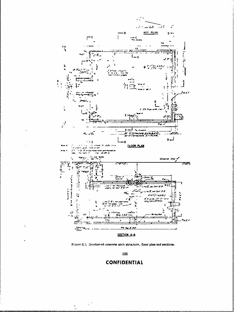
B KEY PLAN , .
*. "P4ii
1I
" ' -i -1
A ~'
4 * . tI
- _ ,. - . . .,--4-, vt __.... -_
I.' '" " - -. " .o: ,Sx :a 5
--
L8- 0
• 9," * .. *~ . =
FLO"
. , . r4--
SECTION A-AFi are G.1 Reinforced -oncrete arch structure, floor plan and sections.
125
CONFIDENTIAL
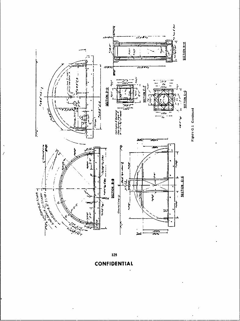
Aw.5
-41 I Lrdg
7,- ' 4t
- ONO,.
CONIDETIA
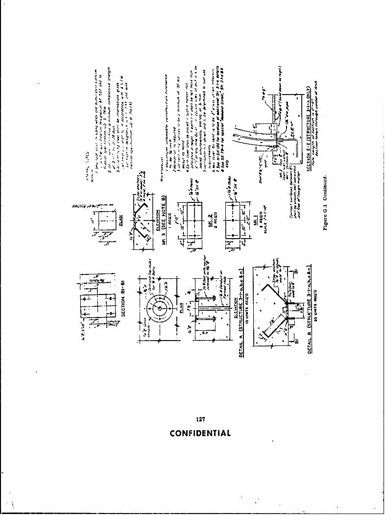
I 'o .i~ 4 "
. r..=c r.~M
iti
oZ, . '- .J.; - I , I j ,.,,, , , e
I.c
:-t- e -,'- S.
1102
D I
ed to b-
:~2~8 co
II :J
*z * - ~~2 cc - 'N ~ Ld
P12COFDETA

At a water content of 3 percent of the optimum water the foundation base of f. • ,tructure.content for standard AAbHO density. Sheepsioot roll- The basic backfill procedu, es are to be identicalera will not be used for compaction of any backfill for for all four structures with the Iullowing exLeptiuns;Project 3.1 installations. (a) Backfilling on Structure 3.1.n must cease for ap-
Soil from the stockpiles to be used for backfilling proximately one half hour to allow Project 3.1 person-has been subjected to extensive compatiun tests. The nel to makc required instrumentation measurementstest results show relately -ide varlatluns in the cLm- when the baclkfill reaches a height of 6 feet Above thepaction characteristics of the soil in individual stock- top of the footings. and ag-un when the backfill ispiles, and that all of the soil is 8 to 15 percent dry of level with the arch crown, and (b) Structures 3.l.a and:he water content required for compaction. As a result, 3.1-b have additional trench excavations with 8-inch-the soil in individual stockpiles will have to be thor- diameter pipes on their south ends. Backfilling shalloughly mixed and sufficient water will have to be added include these trenches, with special precauUonb tkento the scil to increase the water content to 3 percept to protect the 8-inch-diameter pipes they ontaln.dry of optimum before it is plced and compacted as Special precautions must also be taken to protectbackfill. Otherwise, backfill with the requred strength the instrumentation cables coming ou: of the structureRcharacteristic cannot be constructed, into existing irstrumentation trenches on the south end
Equipment and procedures not covered in these of all four structures. Controlled backfilling of t:.ese
instructions may be used if considered satisfactory approximately 3-foot-deep trenches shall extend from
by the Project Officer. Any additional detailed in- the structure base blab for 15 feet.structions, not covered by directives from higher After compaction is finished on all four structures,authority, as to the equipment and procedures to be all waste soil shall be removed from the Project 3.1used in backfilling operations, will be Issued to the area. and disposed of in a manner which shall not in-appropriate contractor supervisory personnel by the terfere with any other project test area.Project Officer. The completion time for the backfill of all fnur
All soil sampling and testing required in connection structures shall be no later than 30 May 1957.with backfilling operations will be performed by Proj-ect 3.8 personnel. Results of completed tests may be G.2.2 Backfill Construction Procedures.obtained by both project and contractor personnelfrom the Project 3.8 field office located in the French- G.2.2.1 Mixing backfill soil. Individualman Flat area. stockpiles of backfill soil shall be thoroughly mixed
Project 3.1 requires the backfilling of four struc- in order to achieve a uniform soil mixture before wa-tures which are identified as: ter is added to the soil. The required mixing shall be
F-3.1-9014.01 (or 3.1.c) accomplished a minimum of 24 hours, and preferablyF-3.1-9014.02 (or 3.1.b) longer, before water is added and the soil stockpiledF-3.1-9014.03 (or 3.1.a) for use as backfill.F-3.1-9015 (or 3.1.n) Mixing of small stockpiles to be used for backfill-
The backfill may start on any one of the four struc- ing Project 3.1 installation shall be accomplished bytures. Once started, the backfilling on each of all casting the entire stockpile with a dragline or clam-four structures shall be a continuous operation without shell from its present location to a new location, thenintermittent delays. recasting the stockpile to another location convenient
There shall be no trash, lumber, debris, or un- for adding water, mixing, and placing the preparedcontrolled soil contained In either the excavated holes soil in the area to be backfllled.or in any backfill soil. G.2.2.2 Adding and Mixing Water into
The final grade of the earth fill for all four struc- Backfill Soil. After backfill soil has been thor-tures shall be the specified natural grade elevation. oughly mixed it shall be placed in windrows of con-The final grade around the structure entrance shall be venient size, and sufficient water shall be added inflush with the top of the structure entrance. increments and mixed Into the soil by means of a pul-
If floods or any similar act of God should be ex- vimixer and motor patrol to raise the water contentperlenced before the backfilling is completed, all com- to that s9; .ified by the Project Officer.pacted and stockpiled backfill soil shall be protected Immediately after the adding and mixing of waterfrom damage by the act. into the backfill soil has been completed, the soil win-
At no time (I.e., during backfill miilng, placement, drow shall be stockpiled at a location convenient toor compaction operations) shall any equipment come the excavation to be backilled. Stockpiling shall beIn contact with or otherwise endanger the soundness accomplished by means of a dragline, clamshell, orof the structures, instruments, instrument cables, or endloader. Stockpiled soil to which water has beeninstrumentation piping, added shall be protected 4-ore drying by covering with
At no time shall heavy equipment and/or earth- tarpaulins, or sprinkling, as required or directed bymoving equipment operate closer to the structure than the Project Officer. Also, stockpiles from which soila vertical plane passing within 6 feet of any part of is being removed and placed for compaction shall be
128
CONFIDENTIAL

maintained in a symmetrical cone shape, anc shall from tim, to time in order to achieve the requirednot be permitted to become ragged, as this would densitj in the backfill. In the event such changes areresult in excess evaporation of water. required, the Project officer will issue instructions
G.2.2.3 Placement of Backfill Soil to be as to the compaction effort to be used.Co mpact ed. All loose soil and debris shall be re- The surface of all compacted lifts shall be pro-moved from excavations to be backfilled prior to the te.ted so as to prevent undue drying out, or wettingplacement of the first lift of backfill soil, and there- from rainfal! or otherwise, by covering with tarpaurafter as required or directed by the Project Officer. lins, o, .;r.'nkling ae required or directed by the
The exposed surface of previously compacted back- Project Officer.fill and the face of th, e, .Vatl,.a up to tne top ot suc-cessive lifts of backfill shall be sprinkled lightly with G.3 CONCRETEwater to insure bonding of the backfill. Ponding ofwater on the surface of compacted lifts will not be per- The work covered by this section of the specifica-mitted. Any surfaces of previously compacted lifts tions consists in furnishing all plant, labor, equip-that appear too hard or glazed tW insure bonding with ment, appliances, and materials, and in performingthe next lift to be placed shall be scarified if so di- all operations in connection with the installation ofrected by the Project Officer. concrete work, complete, in strict accordance with
All soil placed as backfill shall be obtained from this section rf the specifications and the applicablepreviously prepared stockpiles. The plating of soil drawings, and subject to the terms and conditions ofdirectly from windrows into areas to be backfilled the contract. Full cooperation shall be given otherwill not be permitted. trades to install embedded items. Suitable templates
The soil will be placed in lifts of uniform thickness or instructions, or both, will be provided for settingsufficient to result in compacted lifts of 4 inches. In items not placed in the forms. Embedded items shallorder to insure uniformity of lift thickness the place- have been inspected, and tests for concrete and otherment of successive lifts of loose backfill shall be con- materiale or for mechanical operations shill havetrolled by grade stakes. Starting at the bottom of the been completed and approved, before concrete isexcavation, grade stakes for placement of backfill will placed.be set at successive heights of 4 inches above the bot-tom. In the event of undercompaction. or overcom- G.3.1 Applicable Specifications. The followingpaction, the Project Officer may order changes in the specifications, standards, and publications, of thethickness of the lifts to be placed and compacted, issues listed below but referred to thereafter by basic
Loose soil that is permitted to become too wet, or designation only. forr a part of this specification:
too dry, from any cause whatsoever after it has been a. Federal Specifications:placed for compaction shall be removed and replaced P-O-361 (CRD-C 508) Oil. Floor; Mineral.with backfill of the proper water content, if so directed QQ-B-71a (CRD-C 500) Bars; Reinforcementby the Project Officer. for Concrete.
The backfill shall be placed in alternate layers SS-C-158C (CRD-C 201) Cements. HydraulIc;from both sides of the ctructures, maintaining as General Specifications.nearly as practicable a uniform height of backfill at SS-A-281b (CRD-C 131) Aggregate; forall times. In no case shall the backfill on one side Portland-Cement Concrete.be carried more than 12 inches higher than on the SS-C-192b (CIi,'-C 200) Cements, Portland.opposite side of the structure. O-C-106a (CRD-C 505) Calcium Chloride;
Special care must be taken when backhilling and Hydrated, Technical Grade.compacting within 2 eet of all instrumentation pres- SS-C-197 (CRD-C 251) Cement, Portlandsure gages (total 22 for all structures) mounted onthe outside surface of the structures. Project 3.1 SS-C-197 (CRD-C 251) Cement, PortlandProject Officer will give explicit on-the-job Instruc- Blast Furnace Slag.tions concerning hand-tamping over and around b. Corps of Engineers Specifications:these instrumentation pressure cells on the Project - CRD-C-5-52 Slump of Portland Cement Con-3.1 structures. crete.
G.2.2.4 Compaction. Compaction by mechan- CRD-C-300-52 Pigmented Membrane-Formingical tampers shall be performed in a manner that will Compounds for Curing Concrete.Insure uniform application of compaction effort to the CRD-C-16 Method of Testing for Flexuralentire surface of each lift to be compacted. At the Strength of Concrete.start of backfilling and compaction operations at eachinstallation, each unit of surface area of each loose c. American Society for Testing Materialslift equal in area to the area of the tamping foot of the Standards:tampers shall be compacted by 25 blows of the tamper. A-305 (CRD-C 506) Mirmum RequirementsIt may be necessary to vry the compaction effort for the Deformation of Deformed Steel Bare
129
CONFIDENTIAL
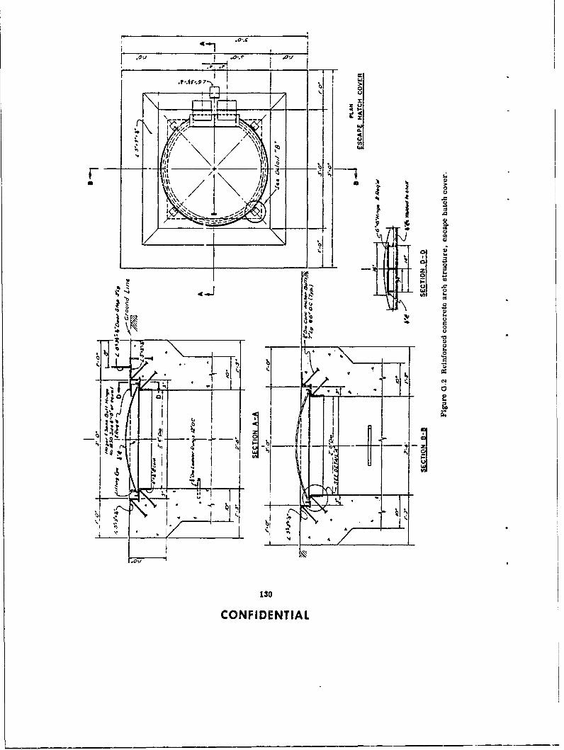
*I I
" I ' I
Ij,\ / \!,,i
lfII -I
t * 'c
* "C) €
r, I. .. . . . . ..
_k_.2Z " - 0
tC
CONFIENTcA

z'i
Z41.4z
IQ 4
cn
131~CONFIDENTIA

for Concrete Reinforcement. (4) Form oil: Fedetal Specification P-O-361C-31 (CRD-C 1!) Making and Curing Concrete (CRD-C 508).
Compression and Flexure Test Specimens in (5) Form ties 'lhall be of approved design, fixedthe Field. or adjustable in length, free of devices which will
C-39 (CRD-C 14) Compressive Streng.h of leave a hole larger than Is inch in diameter in aurface
Molded Concrete Cylinders. of concrete.C-40 (CRD-C 121) Organic Imp rities ,n Sands g. Reinforcement:
for Concrete. (1) Bars: Federal Specification QQ-B-71 (CRD-C-42 (CRD-C 27) Securing, Pr"-'b .o and C 500). type B. grade 2, intermediate billet. Deforma-
Testing Specimens from Har mn d -. ncrete tions shall conform to ASTM Standard A-305 (CRD-C
for Compressive and Flexur.l .. t' tighs. 506).C-94 (CRD-C 31) Ready Mixed 1 o:icretl.. (2) Mill reports: Certified copies of mill reports
C-192 (CRD-C 10) Making and :u.'tng Concrete shall accompany deliveries of reinforcing steel.
Compression and Flexure Test lpei.mens in h. Water shall be clean, fresh, and free from in-the Laboratory. Jurious amounts of mineral and organic substances.
C-171 (CRD-C 310) Paper, Concrete-Curing.G.3.3 Admixtures. Admixtures shall be used only
G.3.2 Materials. on written approval of tLe Contracting Officer. Testsa. A. astves: Abrasive aggregate shall be alumi- of admixtures will be made by the Government in ac-
num oxid, or emery graded from particles retained on cordance with applicable Federal or ASTM specifica-a No. 50 sieve to particles passing a No. 8 sieve. tions or as otherwise prescribed.
h. Accelerating agent shall be calcium chlorideconforming to Federal Specification O-C-106 (CRD-C G.3.4 Samples and Testing. Testing of the aggre-505). gate and reinforcement shall be the responsibility of
c. Aggregate: Both coarse and fine aggregate shall the contractor. The testing agency shall be approved.
conform to Federal Specification SS-A-281 (CRD-C Testing of end items is the responsibility of the Go-131). Coarse aggregate shall be well graded from fine eminent. Samples of concrete for strength tests and
to coarse, within prescribed limits. The maximum end items shall be provided and stored by the contrac-size shall be 1 inch foe class A concrete. tor when and as directed.
d. Cement: Only one brand of each type of cement a. Cement shall be tested as prescribed !n the ap-shall be used for exposed concrete in any individual plicable references specification under which it isstructure. Cement reclaimed from cleaning bags or furnished. Cement ,mnay be accepted on the basis ofleaking containers shall not be used. Cement shall be mill tests and the manufacturer's certification of com-used in the sequence of receipt of shipments, unless pliance with the specifications, provided the cement
otherwise directed by the Contracting Officer. is the product of a mill with a record of production of
(1) Portland cement: Federal Specification high-quality cement for the past 3 years. CertificatesSS-C-192 (CRD-C 200), Type 1 or Type 11 (Type I-A or of compliance shall be furnished by the contractor, forType il-A). each mill lot of cement furnished from different mills
(2) High-early-strength Portand cement- Fed- in mixed shipment and for each separate shipment
eral Specification SS-C-192, Type I ) Type IlI-A). from the same mill, prior to use of the cement in the
(3) Portland blast-furnace slag cement: Federal work. This requirement is applicable to cement forSpecification SS-C-197 (CRD-C 251). Job-mixed, ready-mixed, or transit-mxed concrete.
e. Curing materials: Cement proposed for use where no certificate of con-(1) Waterproof paper: ASTM Designation CRD-C pliance is furnished or where, In the opinion of the
310. Contracting Officer, the cement furnished under certif-(2) Mats: Commercial quality of type used for icate of compliance may have become damaged in trans-
the purpose. it, or deteriorrted because of age or improper storage,(3) Burlap: Commercial quality, will be sampled at the mixing site by representatives(4) Membrane curing compounds: Corps of of the Government and tested for conformance to the
Engineers Specification CRD-C 300. specification at no expense to the contractor. Accessf. Forms shall be of wood, metal, or other approved to the cement and facilities for sampling shall be
material and shall conform to the following require- readily afforded the Government's agent. Cementments: being tested shall not be used in the work prior to re-
(1) Wood forms: No. 2 Common or better ceipt by the contractor of written notification from thelumber. Contracting Officer that the cement has satisfactorily
(2) Plywood: Commercial-Standard Douglas fir, passed the 7-day tests. Cement, for Job-mixed con-moisture-resistant, concrete-form plywood, not less crete, failing to meet test requirements shall be re-than 5-ply and at least '/A-inch thick. moved from the site. Cement at batching plantn for
(3) Metal Forms of approved type that will pro- ready-mixed and transit-mixed concrete failing toduce surfaces equal to those specified for wood forms. meet test requirements shall not be used in Govern-
132
CONFIDENTIAL
ment work. expense to the Government.
b. Aggregate shall be tested as prescribed inFederal Specification SS-A-281b (CRD-C 131). In G.3.5 Storage. Storage accommodations shall beaddition, fine aggregate shall be tested for organic subject to approval of the Contracting Officer Andimpurities in conformance with ASTM Standard C-40 shall afford easy access for inspection and identifiea-(CRD-C 121). tion of each shipment in accordance with test reports.
c. Reinforcement: Reinforcing bars shall be a. Cement: Immediately upon receipt at site oftested as prescribed in Federal Specification QQ-B- work, cement shall be stored in a dry. weathertight,71 (CRD-C 500). Ten sample reinforcing bars of 18- properly ventilated structure, with adequate provisioninch length shall be taken from the structure for each for prevention of absorption of moisture.of the following size groups: No. 5 or less, No. 5 to b. Aggregate: Storage piles of aggregate shallNo. 8. and over No. 8. The ten samples shall be se- afford good drainage, preclude inclusion of foreignlected so as to represent a specimen from the wall matter, and preserve the gradation. Sufficient livereinforcement, the floor-slab reinforcement, and the storage shall be maintained to permit segregation ofarch reinforcement. Each sample shall be securely successive shipments, placement of concrete at re-tagged so as to identify the source of the sample with quired rate. and such procedures as heating, Inspec-respect to the structure and shall be forwarded to the tion, and testing.testing iaborntory, as directed by the ContractingOfficer. G.3.6 Forms. Forms, complete with centering,
d. Concrete: The contractor shall provide for cores, and molds, shall be constructed to conform totest purposes 30 compression test cylinders per struc- shape, form, line, and grade required, and shall beture and 10 beam specimens per structure taken dur- maintained sufficiently rigid to prevent deformationing the pours. These samples shall be taken from under load.pours designated by the Contracting Officer. Test a. Design: Joints shall be leakproof and shall bespecimens shall be made and cured in accordance arranged vertically or horizontally to conform to thewith ASTM Standard C-31 (CRD-C 11). Specimens pattern of the design. Forms placed on successiveshall be cured under laboratory conditions except units for continuous surfaces shall be fitted to accu-that the Contracting Officer may require curing under rate alignment to assure a smooth completed surfacefield conditions when he considers that there is a pos- free from irregularities. If adequate foundation forsibility of the air temperature falling below 40" F. snores cannot be secured, trussed supports shall beCylinders shall be tested in accordance with ASTM provided. Temporary openings shall be arranged inStandard C-39. Beams shall be tested in accordance wall forms and where otherwise required, to facilitatewith Corps of Engineers Specifications (CRD-C-16). cleaning and inspection. Lumber once used in formsThe standard age of test for determining concrete shall have nails withdrawn and surfaces to be exposedstrength shall be 28 days, but 7-day test* may be to concrete carefully Pleaned before re-use. Formsused with the permission of the Contracting Officer, shall be readily removable without hammering or pry-provided that the relation between the 7-day and 28- tog against the concrete.day trength of the concrete Is established by tests b. Form ties shall be of suitable design and ade-for the materials and properties used. Some specd- quate strength for the purpose. Bolts and rods whichmens will be tested at an age designated by the Con- are to be completely withdrawn shall be coated withtracting Officer. If the average of the strength tests grease.of the laboratory control specimens for any portion of c. Joints: Corners and other exposed Joints Inthe work falls below the minimum allowable compres- more than one plane, unless otherwise indicated onsive or flexural strength at 28 days required for the the drawings or directed by the Contracting Officer,class of concrete used in that portion, the Contracting shall be beveled, rounded, or chamfered by moldingsOfficer shall have the right to order a change in the placed in the forms.proportions or the water content of the concrete, or d. Coating:. Forms for exposed surfaces shall beboth, for the remaining portions of the work at the coated with oil before reinforcement Is placed. Sur-contractor's expense. If the average strength of the plus oil on form surfaces and any oil on reinforcingspecimens cured on the job falls below the minimum steel shall be removed. Forms for surfaces not ex-allowable strength, the Contracting Officer may re- posed to view may be thoroughly wet with water inquire changes in the conditions of temperature and lieu of oiling immediately before placing of concrete,moisture necessary to secure the required strength. except that In cold weather with probable freezingWhere there is question as to the quality of the con- temperatures, oiling shall be mandatory.crete in the structure, the Contracting Officer may e. Removal: Forms shall be removed only withrequire tests in accordance with ASTM Standard C-42. approval of the Contracting Officer and in a mannerIn the event that tests indicate that concrete placed to insure complete safety of the structure. Support-does not conform to the drawings and these specifica- ing forms or shoring shall not be removed until mem-tions, measures prescribed by the Contracting Officer bers have acquired sufficient strength to support safe-shall be taken to correct the deficiency at no additional ly their weight and any construction loads to which
133
CONFIDENTIAL

II I-
- - -411
5'.
i. C')
(134
COFIENIA
they may be subjected, but in no case shall they be except as approved by the Contracting Officer. At allremoved in less than 6 days. nor shall forms used points where bars lap or splice. including distributionfor curing be removed before e.Apiration of curing reinforcement, a minimum lap of 30 bar diametersperiod except as provided hereinafter under Section shall be provided. unless otherwise noted.G.3 19, Curing. Care shall be taken to avoia spaiiing a. Design: Reinforcing details shown on the draw-the concrete surface. ings shall govern the furnibhing. fabrication, and
Results of suitable control tests will be used as placing of reinforcing steel. Except ab otherwiseevidence that concrete has attained sufficient strength shown on the dr ngs, or specified, conbtructionto permit removal of supporting forms. Cylinders shall conform to :.e following requirements:required for control tests shall be provided in addi- (1) Conci. :e covering over steel reinforc,-menttion to those otherwise required by this specification. Fsiall be not less than the following thickness:Test specimens shall be removed from molds at end Footings or other principal structural mem-
of 24 hours and stored in the structure as near points bers in which concrete is deposited against the groundof sampling as possible, shall receive invofar as prac- -3 inches between steel and ground.ticable the same protection from the elements during Where concrete surfaces, after removal ofcuring as is given those portions of the structure forms, are exposed to weather or ground- 2 inches.which they represent, and shall not be removed from Whiere surfaces are not directly exposed tothe structures for transmittal to the laboratory prior weather or ground- I inch.to expiration of three fourths of the proposed period (2) Steel in walls shall be as shown on the draw-before removal of forms. In general, supporting ings. Splices shaill be as shown, or shall be furnishedforms or shoring shall not be removed until strength for the approval of the Contracting Officer.of control-test specimens has attained a value of at (3) Shop drawings: Shop dezail and placing draw-least 2.000 pounds. Care must be exercised to assure tngs for all reinforcing steel shall be furimshed for ap-that the newly unsupported portions of the structure proval of the Contracting Oificer.are not subjected to heavy construction or material b. Supports: Reinforcement shall Le accuratelyloading, placed and securely tied at all Interseci ons and splices
Tie-rod clamps to be entirely removed from the with 18-gage black annealed wire, and snail be se-wall shall be loosened 24 hours alter concrete is curely held in position during the placing of concreteplaced, and form ties, except for a sufficient number by spacers, chairs, or other approved supports. %%ireto hold forms in place, may be removed at that time. tie-ends shall point away from the form. UnlessTies wholly withdrawn from vall shall be pulled otherwise indicated on the drawings. or speciied, thetoward inside face. number, type, and spacing of supports shall coniorm
Holes left by bolts or tie rods shall be filled solid to the ACI Detailing Manual (ACI 315). For slibs onwith cement mortar. Holes passing entirely through grade (over earth or over drainage fill) and for foot-wall shall be filled from inside face with a device that ing reinforcement, bars shall be supported on precastwill force the mortar through to outside face, using a concrete blocks, spaced at intervals required by sizestop held at the outside wall surface to insure complete of reinforcement used, to keep reinforcement thefilling. Holes which do not pass entirely through walls minimum height specified above the underside of slabshall be packed full. Excess mortar at face of filled or footing.holes shall be struck off flush.
G.3.8 Class of Concrete and Usage. ConcreteG.3.7 Reinforcing Steel. Reinforcing steel, fabri- shall be one class and shall be proportioned to provide
cated to shapes and dimensions shown, shall be placed a compressive strength at 28 days of 3,000 psi.where indicated on drawings or 'equired to carry outIntent of drawings and specifications. Any changes G.3.9 Proportioning of Concrete Mixes, Concreteshall be approved by the Contracting Officer and noted shall be proportioned by weighi.on the plans. Before being placed, reinforcement a. Measurements: A one-cub.c-foot bag of port-shall be thoroughly cleaned of rust, mill scale, or land cement will be considered as 94 pounds in weight.coating, including ice, that would reduce or destroy One gallon of water will be considered as 8.33 pounds.the bond. Reinforcement reduced in section shall not Coarse aggregate shall be used in the greatest amountbe used. Following any substantial delay in the work consistent with required workability, and shall be ofpreviously placed reinforcement left for future bond- the largest size suitable for the work and economicallying shall be insreeted and cleaned. Reinforcement available.shall not be bent or straightened in a manner injurious b. Corrective additions to remedy deficiencies into the material. Bars with kinks or bends not shown aggregate gradations shall be used only with the writ-on drawings shall not be placed. The heating of rein- ten approval of the Contracting Officer. When suchforcement for bending or straightening will be per- additions are permitted, the material shall be mess-mitted only if entire operation Is approved by the Con- ured separately for each batch of concrete.tracting Officer. In slabs, beams, and girders, re- c. Control: The strength quality of the coneret.inforcement shall be spliced only as shown on drawings proposed for use shall be established by tests mad.)
135
CONFIDENTIAL
in advance of the beginning of operations. using the Percentage Percentageconsistencies sustable for the work. Trial design Material by Weight Material by Weightbatches and testing shall be the responsibility of the CemLnt ± I Fine t 2contractor. Specimens shall be made and cured inaccordance with ASTM Standard C- in (CRD-C 10) aggregateand testa l accordance with ASTUA Standara C-39 Water ± 1 Coarse ± 2(CRD-C 14). A curve representing the relation be- aggregatetween the water content and the average 28-day corn- b. Mixing unit-pressive strength, or earlier strength at which theconcrete is to receive its full working load, shall be (1) o ratoit Mer be charged snexcess of rated capacity nor be oper'.i,.t s ofestablished for the compressive strength called for rated speed. Excesive mixing, requi .ikton ofon the plans. The curve shill be established by at water to preserve required consistency, will not beleast three points, each point representing average permitted. The entire batch shall be discharged be-values from at least four test specimens. The maxi- fore recharging.mum allowable water content for the concrete for thestructure shall be as determined from this curve an (2) Mixing time shall be measured from the in-
stant water is introduced into the drum containing allshall correspond to a strength 15 percent greater solids. All mixing water shall be introduced beforethan indicated on the plans. The final proportions of one fourth of he mixing time has elapsed. Mixingthe mix shall be determined by the Contracting Officer time for mixerv of 1 ydt or less shall be 1i/% minutes;from the results of the trial mixes. The proportions for mixers iarler than 1 yd . mixing time shall beso determined shall be adhered to unless otherwise increased 15 seconds for each additional half cubicdirected by the Contracting Officer. yard or fraction thereof.
In the field, consistency shall be determined in ac- (3) Di-chargo lock: Unless waived by the Con-cordance with CRD-C 5. The slump shall fall etween tracting Officer, a device to lock the discharge mech-2 and 4 inches provided the required strength is oh- anism until thd required mixing time has elapsed shalltained. The slump for nonvibrated concrete when ap- be provided on each mixer.proved by the Contracting Officer shall be from 3 to6 inches. Should the specified strength not be obtained, G.3.11 Ready-mixed Concrete. Re-4 -mixed con-the contractor will be required to vary the mixture suf- crete may be used. unless diapproved tv the Contract-ficiently to meet the requirements but the maximum ing Officer. Except for materials here'n specified.allowable water conto at specified shall not be exceeded, ready-mixed concrete shall conform to ASTM Standart.
C 94 (CRD-C 31).
G.3.12 Construction Joints. Concrete shall beConcrte shall be mixed by a mechanical batch-type placed continuously so that the unit of operation willmng sallbe proied with adechaicate faclltech-t be monolithic in construction. At least 48 hours shallmixing plant provided with adequate facilities for ac- elapse between the casting of ad.ining units, unlesscurate measurement and control of each material to- this requirement is waived by te .ontracting Officer.Wring the mixer and for changing the proportions to Lifts shall terminate at such le, els as are indicated
conform to varying conditions of the work. The mixing- on the drawings, or as conform to structural require-plant assembly shall permit ready inspection of opera- ments, or as directed by the Contracting Officer.tions at all times. The plant and its location shall be Special provision shall be made for jointing success-subject to approval by the Contracting Officer. ive pours as detailed on drawings or requi'ed by the
a. Batching units shall be supplied with the follow- Contracting Officer.ing items:
(1) Weighing unit shall be provided for each type G.3.13 Preparation for Placing. Water shall beof material to indicate the scale load at convenient removed from excavation before concrete is deposited.stages of the weighing operations. Weighing units Any flow of water shall be diverted through proper sideshall be checked at times directed by and in the pre- drains and shall be removed without washing oversence of the Contracting Officer, and required adjust- freshly deposited concrete. Hardened concrete, de-ments shall be made before further use. bris, and foreign materials shall be removed from in-
(2) Water mechanism shall be tight, with the terior of forms and from inner surfaces of mixing andvalves interlocked so that the discharge valves cannot conveying equipment. Reinforcement shall be securedbe opened before the filling valve is fully closed, and In position, inspected, and approved by th Contract-shall be fitted with a graduated gage. Lng Officer before pouring of concrete. Runways shall
be provided for wheeled concrete-handiing equipment;(3) Discharge gate shall control the mix to pro- suc.h equipment shall not be wheeled over reinforce-
duce a ribboning and mixing of cement with aggregate. ment nor shall runways be supported on reinforcement.Delivery of materials from the batching equipment tothe mixer shall be accurate within the following limits: G.3.14 Placing Concrete. The use of belt convey-
136
CONFIDENTIAL

ore, chutes, or other similar equipment will Dot be sections set at approximately the same slope, namely,
permitted without written approval by the Contracting not less than I vertical to 3 horizontal nor more thanOfficer. Concrete shall be handled from mixer or I vertical to 2 horizontal. The dlscharie end of the
transport vehicle to piace of final deposit in a con- chute stiall be provided with a baffle plate to prevent
tinuous manner, as rapidly as practicable, and without segregation. If the height of the discharge end of
segregation or loss of ingi edtent. until the approved chute is more than 3 times the thikness of layer be-
unit of operation is completed. Concrete that has at- lag deposited, but not more than 5 feet above suriacetained its initial set or has conta:ned its mixing water of concrete in forms, a spout shall be used, and thefor more than 45 minutes shall not be placed in the loier end maintained as near surface of deposit as
work. Placing will not be permitted when. in the opin- practicable. When pouring Is intermittent, the chute
ton of the Contracting Officer. the sun, heat, wind, or shall discharge into a hopper. The chute shal belimitations of facilities furnished by the contractor thoroughly cleaned efore and after each run. Wasteprevent proper finishing and curing of the concrete. material and flushing water shall be discharged out-Forms or reinforcement shall not be splashed with side the forms.concrete in advance of pouring. Concrete shall be d. Pump placement: WThere concrete is conveyed
nlaced In the forms as nearly as practicable in final and placed by pumping, the plant and equipment shall
position. Immediately after placing, concrete shall be approved by the Contracting Officer. Operation of
be compacted by thoroughly agitating in an approved pump shall be such that a continuous stream of con-manner. Tapping or other external vibration of forms crete without Air po.kets is produced. %,hen pumping
will not be permitted. Concrete shall not be placed is completed. concrete to be used remaining in pipe-
on concrete sufficiently hard ta cause formation of line shall be ejected without contamination of concreteseams and planes of weakness within the section. Con- or separation of ingredients. After each operation.
crete shall not be allowed to drop freely more than 5 equipment shall be thoroughly cleaned, and debris
feet in unexposed work nor more than 3 feet In exposed and flushing water shall be washed outside forms.work; where greater drops are required, a tremie or
other approved means shall be employed. The dis- G.3.15 Compaction. Concrete shall be placed incharge of the tremies shall be controlled so that the layers not over 12 inches deep. Each layer shall be
concrete may be effectively compacted into horizontal compacted by mecLanical interaAl-vibrating equip-
layers not more than 12 inches thick, and the spacing ment supplemented by hand spading, rodding, andof the tremles shall be such that segregation does not tamping as directed by the Contracting Officer. Vi-
occur. brators shall in no case be used to transport concretea. Placing temperature during cold weather. Con- inside forms. "se of form vibrators will not be per-
crete shall not be placed when the ambient tempera- mitted. Internal vibrators shall maintain a speed of
ture is below 35" F nor when the concrete without spe- not less than 6,000 impulses per minute when sub-
cial protection is likely to be subjected to freezing merged in the concrete. Duration of vibration shalltemperature before final set has occurred. The tern- be limited to time necessary to produce satisfactoryperat-re of the concrete when placed shall be not less consolidation without causing objectionable segregation
than 40'F nor more than 60' F. Heating of the mix- and shall be at least 20 seconds psf of exposed surface.
iag water and/or aggregates will not be permitted until The vibrator shall not be inserted into lower coursesthe temperature of the concrete has decreased to 45" F. that have begun to set. Vibrators shall be applied at
Heated materials shall be free from ice, snow, and uniformly spaced points not farther apart than thefrozen lumps before ento: ng the mixer. Methods and visible effectivcness of the machine.equipment for heating shall be subject to approval bythe Contracting Officer. Suitable means shall also be G.3.16 Bonding and Grouting. Before depositing
provided for maintaining the concrete at a temperature new concrete on or against concrete that has set,
of at least 40*F for not less than 72 ours after plac- existing surfaces shall be thoroughly roughened and
ing. Salt, chemicals, or other foreign materials shall cleaned of latance, foreign matter, and loose parti-
not be mixed with the concrete to prevent freezing. cles. Forms shall be re-tightened and existing sur-
Any concrete damaged by freezing shall be removed faces slushed with a grout coat conaisting of cement
and replaced at the expense of the contractor. and fine aggregate in the same proportions as coo-
b. Earth-foundation placement Concrete footings crete to be placed. New concrete shall bf, placed be-
shall be placed upon indisturbed clean surfaces, free fore the grout has attained initial set. Horizontal
from frost, ice, mud, and water. When the founda- construction joints shall be given a brush coat of
tion is on dry soil o, pervious material, waterproof grout consisting of cement and fine aggregate in same
sheathing par shall be laid over earth surfaces to proportion as concrete to be placed, followed by ap-
receive concrete. proximately 3 inches of concrete of regular mix ex-
c. Chute placement: When, upon written approval cept that the proportion of coarse aggregate shall be
of the Contracting Officer, concrete is conveyed by reduced 50 percent. Grout for setting metal Items
chute, there shall be a continuous flow of concrete. shall be composed of equal parts of sand and portland
The chute shall be of metal or metal-lined wood, with cement, w~h water sufficient to produce required
137
CONFIDENTIAL
consistency. tion consists in !.u: .s.,hing all plant. labor, ecuipmtappliances. aWd materials, and in performing all op-
G.3.17 Slabs on Grade. Any 'ill .ndicated or re- erations in connecuon with the installation of miscel-
quired to raise the subgrade shall be installed as ,aneous metalwork. complete. Including all shelf
specified under Section G. , EXCAVATION. FILLING. angles attacht-d to the concrete, all steel hatches, allAND BACKFILLING. Concrete shall be compacted, pipe sleeves. ini.erts. and anchor bolts, and miscel-
screded to grade. and prepared for the specified laneous bars, plates, and other accestorles necessaryfinish. for the completion of the work in strict accordance
G.3.18 Concrete Floor Finish. Concrete floor with this section of the specifications and the applicable
slabs shall be screeded and wvod floated tW the re- drawings, and subject to the terms and codtions of
quired level of the finished floors, as shown on the the coutract.
drawings. G.4.1 Applicable Specifications and Codes. The
G.3.19 Cr.-:4g. Curing shall be accomplished by folioilig specifications and codes form a part of this
preventing loss of moisture, rapid ttmperature change. specificaton:
and mechanical injury or injury from rain or flowing a. Federal Specifications:water for a period of 7 dayb when normal portland ce- QQ-S-741 and Am-3 Steel. Structural (including
ment has be.n used or 3 days when high-early-strength Welding) and Rivet; (for) Bridges aM. Buildings.portland cement has been used. Curing shall be WW-P-406 and Am-I Pipe; Steel and Ferrous-
atartet. as soon after placing and finishing as free Alloy (for) Urdinary Uses (Iron-Pipe Size).water has disappeared from the surface of the con- (CRD-C 529).
crete. Curing may be accomplished by any of the TT-P-86A Type I and 11 Red Lead Primer.following melhods or combination thereof, as approved TT-A-468A Type U1 Class B Aluminum Pig-by the Contracting Officer. ment.
a. Moist curing: Unformed surfaces shall be TT-V-81B Type HI Class B Varnish. Mixing.covered with burlap, cotton, or other approved fabricmats, or with sand and shall be kept contiaually wet. b. American Institute of Steel Construction Pub-
Forms shall be kept continually wet and If removed lications:
before the eid of the curing period, curing shall be Code of Standard Practice for Steel Build: gn
continued as on unformed surfaces, using suitable and Bridges.
materials. Burlap shall be used only on surfaces Specification for the Design. Fabrication and
which will be unexposed in the finished work and shall Erection of Structural Steel for Buildings.
be in two layers. c. American Welding Society Code:.
b. Waterproof-paper curing: Surfaces shall be - Arc and Gas Welding in Building Coestruction.covered with waterproof paper lapped 4 inches atedges and ends and sealed. Paper shall be weighted G.4.2 General.to prevent displacement, and tears or holes appearing a. Shop drawings: Shop drawings of all items ofduring the curing period shall be immediately repaired miscellaneous metalwork shall be submitted to theby patching. Contracting Officer for approval. Material fabricated
c. Membrane curing: Membrane curing compound or delivered to the site before the approved shop draw-shall be applied by power spraying equipment using a Itgs have been received by the contractor hall be oub-
3pray nozzle equipped with a wind guard. The corn- ject to rejection by the Contracting Officer.pound shall be applied in a two-coat, continuous opera- b. Mill reports: The contractor shall frnish,tion at a coverage of not more than 200 it i/gal for both without extra cost to the Government, two certifiedcoats. When application is made by hand sprayers, copies of all mill reports covering the chemical andthe second coat shall be applied in a direction approxi- physical propertie& of the -. cel used in the -.,ork uLder
mately at right angles to the direction of the first coat. this specification.The compound shall form a uniform, continuous, ad- c. Substitutions: Subetltutions of sections, orherent film that shall not check, crack, or peel, .nd modificatione of details, )r both, aail be made only
shal' be free from pinholes or other Imperfections. when approved by the Contracting Officer providing,
Surfaces subjected to heavy rainfall within 3 hours however, the strength and stiffness shall be at leastafter compound has been applied or surface damaged equal to the original design.by subsequent construction operations within the cur- d. Responsibility for errors: The contractor aloneing period shall be resprayed at the rate specified shall be responsible for all errors of fabrication andabove. Surfaces coated with curing compound shall for the correct fitting of the structural membersbe kept free of foot and vehicular traffic and other shown on the shop drawings.sources of abrasion during the curing period.
G.4 MISCELLANLOUS METALWORK G-4.3 Materials.a. Structural steel: Structural stee shall conform
The work covered by this section of the specifica- to tLb requirements of Federal Specilcations QQ-S-
138
CONFIDENTIAL
''1 aiid Am-3. Type I or 11. G.atde B, Class 1. installed as shown on the dt-sign drawings.b. Anchor bolts: All Anchor bolts shall coniorm
to the requirements for structural steel. G.4.5 Inspection and Tests. The material to bec. Sleq',es: l'ilw slec~es for anchor bolts ,hall fi-riheil under tlub slit, i:i~ati.,n shall lbe subject to
cvnform to the rtequirenit nis *ij Ft tieral Spet.ifit ition in.spection and tests in the mill. shop, and field by%%%-P-406 and Am-I (CIID-C 5-14). authorized Goverinment inspectors. Inspevction .u'J
d. Mainhole rungs INlanhch* r.n:s t-hall be 1mbh- tests will be conducted without expense to the coijtrsc-mann and Barnard. Znt., _'04 Ea%i~:..rd Street. New tor. however. inbpectitn in the mill or shop shill notYork Ciry. Style P or equal. reiieve the contractor of his icsponsibility to reject
anv matertil at any time before final acceptance ofI.1 F-tbriecition. Insofair as~ possible. work shall the building %hen, in the opinion of the Contracting
be iittLd(Fnd shop assembled. ready for crectic-a. Officer. th~e niaterial.% and workmanship do not con-%%ork shall conform to the dr-owings, details, and ap- form to thu. specification requirementsb. Test speci-proved slt )p drawings. thop at i field connections nitns shall be made Of bUfficient number to determineshall be welded. attich%., 'ith ,t. rvws. andi sinidar the averag( yield point stress [or the various struc-fastenings, all in accmo. nev with ai high standard of tures.workmanship for the 0a: - of work concerned, and asapproved by zhe Contracting Olffter. Jointing and in- G.4.6 Desiktn. The design of members and con-tersections sh,-1 be accuraitul) made in true planes, nections lor al FPurtionsb o1 the structure are indiLatedtightl~l Iitted and dr awn up. welded, and dressed on the drawings. in the 4Lvent that it is d'emed neces-smooth. sary to modify or change an% member or connections
a rial~anizing- %%herever gal% anizing is called for such design drawings shall be submitt'd to the Con-on the draw!,4s the mietal shall be hot-dip galvanized tracting Officer for approval .efore any material isafter f.;brication, using not less tha.n 2 ounces of zinc fabricated. Substequent to appjroval b) the Contractingper square loot of surface area in conformance with Officer, no ... anges or modtficationb shall be madethe current AST&I Specification A-123. All parts to without his consent.h,! calvani 'd shall be thoroughly :leaned and pickledbefore gadvani-ing. G.4.7 Painting. All iron and steelwork except that
b. Miscellaneous: Items not specifically referred which is shown or specified as galvanized shall be*to above shall be i rnished. constructed, and installed cleaned of all dirt, scale, and rust and shall be give.n
as shouta on the d& vings or as approves by the Con- one shop coat of red lead in oil primer conforming totracting Vficer. Federal Specification TT-P-46A Type I or 11. After
c. Escape hat(-N door: The escape hatch dloor and erection all abraded surfaces shall be touched up withall rr.!tcellaneous accessories shall be fabricated and shop paint.
CO0NFiDENTiAL

REFERENCESI. L.J. Vortman, "Effects of an Atomic Explosion on Group- and Family-type Personnel Shelters";
Projects 34.1 and 34.3, Operation Teapot. WT-116?, January 1957, Sandia Corporation, Albuquerque, NewMexico, Secret. Restricted Data.
2. C. L. Haven, "U.S. Navy Structures"; Annex 3.2, Operation Greenhouse. WT-91, 8 April 1955; Bureauof Yards and Docks. Navy Department. Washington 25, D. C.; Secret, Security Information.
3. R. M. Longmire and L. D Mtills, "Navy Structures"; Projects 3.11-3.16, Operation Upshot-Knothole,WT-729. Mday 1955, Bureau of Yards and Docks, Department of the Navy. Washington 25, D. C.; Confiden-tial. Restricted Data.
4. R. B. Vaile, Jr. and L. D. Mills, "Evaluation of Earth Cover as Protection to Aboveground Structures";Project 3.6. Operation Teapot, WT-1128, December 1956, Bureau of Yards and Docks, Department of theNavy, Washington 25, D.C. ; Confidential. Restricted Data.
5. "The Design o[ Structures to Resist the Effects of Atomic Weapons"; EM 1110-345-414 to 421, 15.March 1957, Massachusetts Institute of Technolgy,, for Office of the Chief of Engineers, U.S. Army.Washington. D.C.; Unclassified.
6. N.M. Newmark, G.K. Sinnamon. and F. Matsuda; "Air Blast Effects on Underground Structures";Project 3.4, Operation Teapot WT-1127. May 1955, for Office, Chief of Engineers, U.S. Army, Washing-ton, D.C.; Confidential. Restricted Data.
7. N. M. Newmiark and G. K. Sinnamon; "Air Blast Effects on Underground Structures"; Project 3.8,Operation Upshot-Knothole, WT-727, January 1954; for Office. Chief of Engineers, U.S. Army, Washing-ton 25, D.C.; Confidential, Restricted Data.
8. D. T. Robbins, "Analysis Report for Basic Types of Underground Strictures"; Contract No. DA-22-079-eng-196 with Holmes3 and Narver, Inc., October 1956, U.S. Army Engineers Waterways ExperimentStation, Corps of Engineers, Vicksburg, Mississippi; Secret, Restricted Data.
9. N.M. Newmark, "Vulner3bility of Arches - Preliminary Notes"; Revised 21 May 1956; University ofIllinois, Unpublished; Unclassified.
10. E. Cohen, "Design Report for Three Basic Types of Underground Structures"; Contract No. DA-22-079-eng-195 with Ammann and Whitney, Consulting Engineers, August 1956; U.S. Army Engineers Water-ways Experiment Station, Corps of Engineers, Vicksburg, Mississippi; Unclassified.
11. T. B. Goode and others; "Soil Survey and Backfill Control in Frenchman Flat'; Draft Manuscript,Project 3.8, Operation Plumbbob, WT-1427, 27 November 1957, U.S. Array Engineer Waterways Experi-ment Station, Corps of Engineers, Vicksburg, Mississippi; Unclassified.
12. J. W. Wistor and W. R. Perret; "Ground Motion Stadles at High Incident Overpressure"; Project 1.5,Operation Plumbbob, ITR-1405, 11 October 1957, Sandia Corporation, Albuquerque, New Mexico; Confiden-tial. Formerly Restricted Data.
13. W.J. Flathau and R.A. Cameron; "Damage to Existing EPG Structures", Project 3.7, OperationHardtack. ITR-1631. June 1958, U.S. Army Engineer Waterways Experiment Station, Corps of Engineers,Vicksburg, Mississippi, and Holmes and Narver, Inc., Los Angeles, California; Secret, Formerly Re-stricted Data.
14. "Capabilities of Atomic Weapons", Department of the Army Technical Manual TM 23-200, RevisedEdition, November 1957; Confidential.
15. D.T. Robbins and R.A. Williamson; "Po;t-Shot Analysis for Project 3.1, Operation Plumbbob";Contract No. DA-12-079-eng-196, Modification No. 3, with Holmes and Narver, Inc., April 1958; U.S.Army Engineer %\aterways Experiment Station, Corpb of Engineers, Vicksburg, Mississippi; Confidential.
140
CONFIDENTIAL
16. N.M. Newmark. "Recommended FCDA Specifications for Blast Resistant Structural Design - MethodA"; Preliminary, 9 August 1957; Unclassified.
17. N.M. Newmark. "Designing for Atomic Blast Protection"; Proceedings of the Structural EngineersAssociation of California, Twenty-fifth Annual Convention, Reno, Nevada, October 1956, Unclassified.
18. J.J. Meszaros, H.S. Burden, and J. D. Day; "Instrumentation of Structures for Air-Blast and
Ground-Shock Effects"; Project 3.7. Operation Plumbbob, ITR-1426, 6 December 1957, Ballistic ResearchLaboratories. Aberdeen Proving Ground, Maryland. Unclassified.
19. L. M. Swift, D.C. Sachs, and F. M. Sauer; "Ground Acceleration. Stress, and Strain at High IncidentOverpressures". Project 1.4. Operation Plumbbob, ITR-1404, 11 October 1957, Stanford Research Izstitute.Menlo Park, California; Confidential, Formerly Restricted Data.
20. A. P. Flynn; "FCDA Family Shelter Evaluation"; Project 9.1a, Operation Buster. WT-359, March1952; Confidential, Formerly Restricted Data.
21. J.R. Hendrickson and others. "Shielding Studies", Project 2.7, Operation Teapot, WT-1121, Febru-ary 1957; Chemical Warfare Laboratories, Army Chemical Center, Maryland; Secret, Restricted Daa.
22. Theodore Rockwell, IIl; "Reactor Shielding Design Manual"; AEC-TID 7004. USAEC, March 1956,page 261 ff; Unclassified.
23. R.G. Larrick and others; "Gamma Exposure versus Distance"; Project 2.1. Operation Teapot,ITR-1115, May 1955; Confidential, Formerly Restricted Data.
24. M. Ehrlich "Photographic Dosimetry of X- and Gamma Rays"; Handbook 57, August 1954, page 10;U.S. Department of Commerce, National Bureau of Standards; Unclassified.
25. M. Ehrlich and S. H. Fitch; "Photographic X- and Gamma Ray Dosimetry"; Nucleonics, September1951, Vol. 9, No. 3, pages 5-17; McGraw-Hill Publishing Company, Inc.; Unclassified.
26. S.C. Sigoloff; "Fast Neutron Insensitive Gamma Ray Dosimeters, the AC and ACTE Systems", inPress; School of Aviation Medicine, USAF, San Antonio, Texas; Unclassified.
27. G.V. Taplin and others; "Measurement of Initial and Residual Radiations by Chemical Methods";Project 39.6, Operation Teapot, ITR-1171; Secret, Restricted Data.
28. D. L. Rigottl, H. 0. Funsten, and J. W. Klnch; "Neutron Flux from Selected Nuclear Devices";Project 2.3, Operation Plumbbob, ITR-1412, March 1958; Secret, Restricted Data.
29. I. G. Bowen. A. F. Strehler. and M. B. Wetherbe; "Distribution and Density of Missiles from NuclearExplosions"; Project 33.4. Operation Teapot, WT-1168, March 1956; Civil Effects Test Group, Washington,D.C.; Unclassified.
30. Hans Desega; "Experimental Investigations of the Action of Dust"; Chap. XII-B, pages 1188-1203,German Aviation Medicine World War II, Vol. U, 1950; U.S. Government Printing Office, Washington, D.C.,Unclassified.
31. S. Ruff; "Brief Acceleration"; Chapter VI-C in German Aviation Medicine, World War ii. pages 584-597. 1950; U.S. Government Printing Office, Washington, D.C.
141- 142
~nFD E hTL

DISTRIBUTION
Military Dstroutiox Category 32
AIM ACTYVITU] 11 Chief, bureau of Ships, DlX, Vasholgton 25t, D.C.AT73: Code 123
1 Deputy Chief of Staff for Military Operations, D/A, 12 Chief, Bureau of ads and wDock , p/N, Washington 25,V asbligton 25, D.C. ATI: DIr. of sw&R D.C. ATMW: D-
2 Chief of Rsearch and Development, D/A, Washington 25, 13 Diroctor, U S. Naval Research Iaborator/, WashlngtonD.C. ATXf: Atomic Div. 25, D.C. ATTZ: Mrs. atherine S. Cass
3 Chief of &.gineers, D/A, Washington 25, D.C. ATTNi: L40 U. 15 Comander, U.S. Naval OrdA nce laboratory, White Oak,
4 Chief of Kogineer", D/A, Washington 25, D.C. A7 R: XZn Silver Spring 19, Md.5 Chief of Zngineers, D/A, Washington 25, D.C. ATM: D= 4.6- 4T Conding Officer, U.S. Naval PtAdological Defense
6. 7 Office. Chief of Ordnance, D/A, Washington 25, D.C. laboratory, Sen Francisco, Calif. A"m: Tech.
A?. CE", Info. Div.
8 Chief of Trariportation, DA, Office of Planning and Int., . 50 Officer-in-Charge, U.S. Naval Civil ZKgineering R& Lab.,
Wasbhizg= 25, D.C. U.S. Naval Ccstruction Sn. Center, Port Ebaneme,9- 11 Canding General, U.S. Continental Army Cmnd, Ft. Calif. ATTN: Code 753
Monroe, Va. 51 Coeanding Officer, U.S. aval Schools Command, U.S.
12 Director of Special Weapons Developeent Office, Bead. Naval Station, Treasure Island, San Francisco, Calif.
quartera CCRAM, Ft. Bliss, Tsx. ATTX: Capt. Chester I. 52 Superintendent, U.S. Naval Postgraduate School, Monterey,
Peterson Calif.
13 President, U.S. Army Artillery Board, U.S. Continental 53 Officer-in-Charge, U.I. Naval School, CD Officers, U.S.
AM Coand, Ft. Sill, Okla. Naval Construction Bn. Center, Port Hueneme, Calif.
11. President, U.S. AriW Air Defense Board, U.S. Continental 5 Commanding Officer, Nuclear Weapons Training Center, Atlantic,Army Cmand, Ft. Bliss, Tex. U.S. Navl Base, Norfolk 11. Va. ATi N: Nuclear Warfare Dept.
1 Comadant, U.S. Army Comand 4 General Staff College, s C.nding Officer, Nuclear Weapons Training Center,
Ft. Lea...orth, anses. ATYB: AFC = Pcific, Naval Station, San Diego, Calif.16 Coandant, U.S. Aray Air Defece School, Ft. Bliss, 56 Ccmending Officer, U.S. aval Dage Control Tag.
Tax. AM5: Dept. of Tactics and Combioed Area Center, Naval Base, PhLladelph'a 12, Pa. A7m: ABC17 Ccandant, U.S. Army Armored School, Ft. Knoz, K. Defense Course.8 Commndant, U.S. Army Artillery and Missile School, 57 Canding Officer, U.S. .aa1 Medical Research Institute,
Ft. SiLl, Okla. ATM: Combat Deve opment Depatemet NatIonal Naval Medical Center, Bethesda, Md.19 Cmndant, U.S. Arm Aviation School, Ft. Rucker, Ala. 5 Commanding Officer and Director, David W. Taylor Model
20 Comndant, U.S. Aimy Infantry School, Ft. Bnning, Basin, Washington 7, D.C. ATT: LibraryGo. AMl: C.D.8. 59 Commander, BorfoIk Naval Shipyard, Portsmouth, Va. ATTN:
21 Comaing General, Chemical Corps Training Coed., Ft. Undervater loplosions Research DivisionMcClellan, Ala.
22 Commandant, UA Transport School, Ft. Custie, Vs. ATIM: 60- 63 Coandant, U.S. Mrio- Corps, Washington 25, D.C.
Security and Info. Off. AI Cm d e 3 S23 Coeanding General, The Zngineer Center, Ft. Bolvoir, Va. 61. Cmanding Officer. U.S. Naval CIC School, U.S. Navel Air
ATTS: Aset. Cadt, fngr. School Station, Glynco, Bnrusvick, Ga.
21 Director, Armed Forces Institute of Pathology, Walter Ant AReed Army Md. Center, 625 16th St., VWt, Washington
25, D.C.25 Ceanding Officer, ArmC Medical R Lab., Ft. 65 Assistant for Atomic Knergy, SQ, W, Washington 25,
noe, Ky. D.C. ATI: Dl/O
26 Coandant, Walter Read AM lnst. of Res., Walter 66 Deputy Ch,ef of Staff, Operations EA. USAF, Washington
Reed Areq Medical Center, Washington 25, D.C 25, D.C. ATT: Operations Analysis27-28 o i Officer, Ceicare, l . , . 67 Director of Civil ELineering, SQ. USAF, Washington 25, D.C.
27- 28 Commanding Officer, Chemical Warfare lab., Arvq ATTN: AFOC
Chemical Center, Md. AlTM: Tech. Llbrar7 68- 69 Assistant Chief of Staff, Intelligence, EQ. WUA,29 Comanding General, Engineer Research and Day. lab., Washington 25, D.C. ATTIN: AFI2rX-IB2
Ft. Belvoir, Va. ATTN: Chief, Tech. Support Branch 70 Director of Research and Developeent, LCS/D, Mi. USAF,
30 Director, Waterarys ,xperinent Station, P.O. Box 631, Washington 25, D.C. ATTN: Guidance and Weapons Div.Vicksburg, Miss. ATM!: Library 71 The Surgeon General, 94. USAF, Washington 25, D.C.
31- 32 Cmmanding Gerarnl, Aberdeen Proving Grounds, Md. ATTN. A".. Bio.-Def. Pre. Mod. DivisionDirector, Ballistics Research laboratory 72 Coswander-in-Chief, Strategic Air Comand, Offut AFB,
33 Comanding General, Ordnance Ammunition Ccand, Joliet, Neb. ATrI: AWSIll. 73 Coxnander, Tactical Air Comand, Langley AFB, Va. AT=:
31 Director, Operations Research Office, Johns Bopkins Doc. Security Branchcaiversity, 6935 Arlington Rd., Bethesda 11, Md. 71. Comander, Air Defense Comaad, Rat AlB, Colorado.
35 Cmmander-in-Chlef, U.S. Army uropa, APO 403, New Tork, ATTN: Atomic Knergy Div., ADIAN-AN.Y. API!: Opot. Di., Weapons Br. T5 Coander, Sq. Air Research and Development Camand,
Andrevs AM, Washin.ton 25. D.C. ATTX: IDWA
NAVY ACTTCTTE 16 Cmmander, Air Force Ballistic Missile Div., i. AIM, AirForce Unit Poet Office, Los Angeles 1.5, Calif. ATTN: WDSOT
36 Chief of Naval C-erstlons, D/N, Washington 25, D.C. 77- 78 Conder, AT Casbridge Research Center, L. G. Hanscan
APIII: OP-OAG Field, Bedford, Kass. ATIN: CAS?-237 Chief of Naval Operations, D/X, Washington 2!k, D.C. 79- 83 Commander, Air Force Special Weapons Center, Kirtland AnJ,
ATM. O-36 Albuquerque, N. Max. ATTS: Tech. Inf. & Intel. Div.
38.- 39 Chief of level Research, D/X, Washington 25, D.C. 84- 8 Director, Air University Library, Maxvell All, Ala.
AIN: Code ll Cmandr, Lowy Al, Denver, Colorado. ATTN: Dept. of10 Chief, bureau of Ordnance, D/N, Washington 25, D.C. ft. Vpn. Tug.
143

87 Commeandant, kcnool1 of Aviation M4edicine, LWA, Randolph lo9 Ccmaendr, Field Command, AFYiP, Stadia BLAa, Albuquerque,
UNtCLASSIFIED e. .W aantnAfNTB .
ASS, Tax. A"1 : Research.Secretariat -14 . Mex.* A73: TM88 Coander, 1009th Sp. Wrs. Squadron, M. USA.F, Washington 0-l Coudr, Yield Commn, A.MP, Soania ass, Albuquerque,
25, D.C. N. Me. A": F'T59- A1 CocaLer, ri.t Air Devol.ot Con-or, rright-PFattern 15 A=intrator, Ntj~nal ArocautcA and Spc Ada'n stretion,
A", Ayt:, hio. A: -C . ., Washigtn 25, D.C. A"C2- 93 DI ectoir. tA.? Prvo..cl R 1, VIA: USAF Liaison 3ff co,Rhd
:he pASD Corp.. l,) Hen St.. .at* M-mica, Cal 1 1±6 Of.f. iocets oficer, Office of tle Ur.lted States9. Comnder, Pocia A.r Dvelopment Center, A=t, Griffis AY3, National Mljta-7 Representative - SWAP, APO 55,
N. T. A.". : T.he Documon's Library FCCSSID New York, NY95 Asslste.t Chief of Staff, intelligence, 9 . iTSA I, APO
1133, Now Tort, I.T. A-T'I: Directorate of Air Targets ATHC ~ c.s oir sA'96 Cocander-Lin-Ch ef, Pacific Air Forces, A.'2 )53, San
Francisco, Cal"i. AT".: P.Cul-K3, Base Recovery117-LI9 U.S. Atoic Iorgy Cozmisslon, cbicalI Library,
0-,M UPARI4IT OF W ACTIIT= Washington 25, D.C. ATN: For IVAL0-121 oe Alamo Scientific Laboratory, Report Library, P.O.
97 Director if Deferse Research rA ftgineering, Washington 25, Box 1663, Los Alazos, N. Max. A"IN : Helen Red=nD.C. ATI: Tech. L'brary 122-126 Saadia Corporation, Classified Dcuent Division, Sandia
ha.ra , Armed Ser,'ces Explosives Safety Board, DOD, Base, Albuquerque, X. Mex. ATIM: H. J. Smyth, Jr.3uild~n g T-., ,ravolly PF-it, Washington 25, D.C. 127-129 University f California Radiation Laboratory, P.O. Box
99 Director, Weapons Sbytas Xral-.ati-n Group, FOta 1ITS8, W0, Liver=ore, Calif. AIR: Clovis G. CraigTte Pentagon, ashlrngton 25, D.C. 130 Weapon Data Section, Technical Infomation Service
100-107 Chief, Armed Forces Special Weapons Project, Washingt on Xxtenslon, Oak Ridge, Tenn.15, D.C. 131-165 Teclhnical :fo:atlon Service Extension, O.k Ridge,
108 Com.a.er, Field Coiaand, AYMB P, Sandia Base, Albuquerque, Ten. (S~urplus).. Max.
UNCLASSIFIED144
Ana
Lr._MENTA iy
A
INFORMAT-ION
Defense Nuclear Agency6801 Telegraph Road
Alexandria, Virginia 22310-3398
SSLERRATA 14 September 1995
MEMORANDUM TO DEFENSE TECHNICAL INFORMATION CENTERATTN: OCD/Mr Bill Bush
SUBJECT: Change of Distribution Statement
The following documents have been downgraded to Unclassifiedand the distribution statement changed to Statement A:
WT-1307, AD-311926 WT-1305, AD-361774POR-2011, AD-352684 WT-1303, AD-339277WT-1405, AD-611229 WT-1408, AD-344937WT-1420, AD-B001855 WT-1417, AD-360872WT-1423, AD-460283 WT-1348, AD-362108WT-i422, AD-615737 WT-1349, AD-361977WT-1225, AD-460282 WT-1340, AD-357964WT-1437, AD-311158WT-1404, AD-49l310WT-1421, AD-691406WT-1304, AD-357971
If you have any questions, please call MS Ardith Jarrett, at325-1034.
FOR THE DIRECTOR:
4 JOSEPHINE WOOD4Chief
Technical Support
ERRATA
SUPPLEMENTARY
INFORMATION
Defense Nuclear Agency6801 Telegraph Road
Alexandria. Virginia 22310-3398
SSTL ERRAIA 14 September 1995
AI-MEMORANDUM TO DEFENSE TECHNICAL INFORMATION CENTER
ATTN: OCD/Mr Bill Bush
SUBJECT: Change of Distribution Statement
The following documents have been downgraded to Unclassifiedand the distribution statement changed to Statement A:
WT-1307, AD-311926 WT-1305, AD-361774POR-2011, AD-352684 WT-1303, AD-339277WT-1405, AD-611229 WT-1408, AD-344937WT-1420, AD-B001855 WT-1417, AD-360872WT-1423, AD-460283 WT-1348, AD-362108WT-1422, AD-615737 WT-1349, AD-361977WT-1225, AD-460282 WT-1340, AD-357964WT-1437, AD-311158WT-1404, AD-491310WT-1421, AD-691406WT-1304, AD-357971
If you have any questions, please call MS Ardith Jarrett, at325-1034.
FOR THE DIRECTOR:
4 .JOSEPHINE WOOD
Technical Support
ERRATA
II I I
DATE
IL,
Related Documents