AS/NZS 4331.1:1995 ISO 7005-1:1992 Australian/New Zealand Standard Metallic flanges Part 1: Steel flanges

Welcome message from author
This document is posted to help you gain knowledge. Please leave a comment to let me know what you think about it! Share it to your friends and learn new things together.
Transcript
AS/NZS 4331.1:1995ISO 7005-1:1992
Australian/New Zealand Standard
Metallic flanges
Part 1: Steel flanges
AS/NZS 4331.1:1995
This Joint Australian/New Zealand Standard was prepared by Joint TechnicalCommittee ME/1, Pressure Equipment. It was approved on behalf of the Council ofStandards Australia on 19 July 1995 and on behalf of the council of Standards NewZealand on 24 October 1995. It was published on 5 December 1995.
The following interests are represented on Committee ME/1:
A.C.T. Occupational Health and Safety OfficeAluminium Development Council, AustraliaAustralian Chamber of Commerce and IndustryAustralian Institute of EnergyAustralian Institute of PetroleumAustralian Institute of Pressure Equipment EngineersAustralian Liquefied Petroleum Gas AssociationBoiler and Pressure Vessel Manufacturers Association of AustraliaBureau of Steel Manufacturers of AustraliaDepartment for Industrial Affairs, S.A.Department of Employment, Vocational Education, Training and Industrial
Relations, Qld.Department of Labour, New ZealandDepartment of Occupational Health, Safety and Welfare, W.A.Electricity Corporation of New ZealandElectricity Supply Association of AustraliaHeavy Engineering Research Association, New ZealandInstitute of Metals and Materials, AustralasiaInstitution of Engineers, AustraliaInsurance Council of AustraliaMetal Trades Industry Association of AustraliaNational Association of Testing Authorities, AustraliaNew Zealand Engineering FederationNew Zealand Petrochemical Users GroupNew Zealand Timber Industry FederationOccupational Health and Safety Authority, Vic.Tasmania Development and ResourcesWelding Technology Institute of AustraliaWorkCover Authority, N.S.W.Work Health Authority, N.T.
Review of Standards. To keep abreast of progress in industry, Joint Australian/NewZealand Standards are subject to periodic review and are kept up to date by the issue ofamendments or new editions as necessary. It is important therefore that Standards usersensure that they are in possession of the latest edition, and any amendments thereto.
Full details of all Joint Standards and related publications will be found in the StandardsAustralia and Standards New Zealand Catalogue of Publications; this information issupplemented each month by the magazines ‘The Australian Standard’ and ‘Standards NewZealand’, which subscribing members receive, and which give details of new publications,new editions and amendments, and of withdrawn Standards.
Suggestions for improvements to Joint Standards, addressed to the head office of eitherStandards Australia or Standards New Zealand, are welcomed. Notification of anyinaccuracy or ambiguity found in a Joint Australian/New Zealand Standard should be madewithout delay in order that the matter may be investigated and appropriate action taken.
www.bzfxw.com
AS/NZS 4331.1:1995
Australian/New Zealand Standard
Metallic flanges
Part 1: Steel flanges
PUBLISHED JOINTLY BY:
STANDARDS AUSTRALIA1 The Crescent,Homebush NSW 2140 Australia
STANDARDS NEW ZEALANDLevel 10, Standards House,155 The Terrace,Wellington 6001 New Zealand
ISBN 0 7337 0007 1
www.bzfxw.com
ii
PREFACE
This Standard was prepared by the Joint Standards Australia/Standards New Zealand Committee ME/1 onPressure Equipment. It is identical with and has been reproduced from ISO 7005-1:1992, Metallic flanges,Part 1: Steel flanges.
The objective of this Standard is to provide designers, manufacturers and users with an international Standardfor flanges for use in pressure applications.
This Joint Standard is one of the following series that applies to metallic flanges.
AS/NZS4331 Metallic flanges4331.1 Part 1: Steel flanges4331.2 Part 2: Cast iron flanges4331.3 Part 3: Copper alloy and composite flanges
Under arrangements made between Standards Australia, Standards New Zealand and ISO, users of thisStandard are advised that in Australia copyright is vested in Standards Australia and in New Zealandcopyright is vested in Standards New Zealand.
It is not intended this Standard be a mandatory replacement for any flange Standards already in use inAustralia or New Zealand. Before flanges to this Standard are used with flanges of other Standards,compatibility for bolting, strength, gasket seating and the like should be checked.
Statements expressed in mandatory terms in notes to text, tables and figures are deemed to be requirementsof this Standard.
The terms ‘normative’ and ‘informative’ have been used in this Standard to define the application of theannex to which they apply. A ‘normative’ annex is an integral part of a Standard, whereas an ‘informative’annex is only for information and guidance.
As this Standard is reproduced from an international Standard, the following applies:
(a) Its number appears on the cover and title page while the International Standard number appears only onthe cover.
(b) In the source text, ‘this International Standard’ should read ‘this Australia/New Zealand Standard’.
(c) A full point substitutes for a comma when referring to a decimal marker.
References to international Standards should be replaced by equivalent Australian Standards, as follows:
Reference to International Standard Australian StandardISO7
7-1:1982
7-2:1982
Pipe threads where pressure-tightjoints are made on the threadsPart 1: Designation, dimensions
and tolerancesPart 2: Verification by means of
limit gauges
AS1722
1722.1
1722.1
Pipe threads of Whitworth form
Part 1: Sealing pipe threads
Part 1: Sealing pipe threads
261:1973 ISO general purpose metric screwthreads—General plan
1721 General purpose metric screwthreads
887* Plain washers for metric bolts,screws and nuts for generalpurposes—General plan
—
* To be published (Revision of ISO 887:1983).

www.bzfxw.com
iii
ISO6708:1980 Pipe components—
Definition of nominal size
AS—
7268:1983 Pipe components—Definition of nominal pressure
—
7483:1991 Dimensions of gaskets for usewith flanges to ISO 7005
—
ANSI/ASMEB1.20.1:1983 Pipe threads, general purpose
(inch)
—
Equivalent National Material Standards may be substituted for those specified in this Standard.
© Copyright STANDARDS AUSTRALIA/STANDARDS NEW ZEALAND
Users of Standards are reminded that copyright subsists in all Standards Australia and Standards New Zealand publications and software.Except where the Copyright Act allows and except where provided for below no publications or software produced by Standards Australiaor Standards New Zealand may be reproduced, stored in a retrieval system in any form or transmitted by any means without prior permissionin writing from Standards Australia or Standards New Zealand. Permission may be conditional on an appropriate royalty payment. Australianrequests for permission and information on commercial software royalties should be directed to the head office of Standards Australia. NewZealand requests should be directed to Standards New Zealand.
Up to 10 percent of the technical content pages of a Standard may be copied for use exclusively in-house by purchasers of theStandard without payment of a royalty or advice to Standards Australia or Standards New Zealand.
Inclusion of copyright material in computer software programs is also permitted without royalty payment provided such programsare used exclusively in-house by the creators of the programs.
Care should be taken to ensure that material used is from the current edition of the Standard and that it is updated whenever the Standard isamended or revised. The number and date of the Standard should therefore be clearly identified.
The use of material in print form or in computer software programs to be used commercially, with or without payment, or in commercialcontracts is subject to the payment of a royalty. This policy may be varied by Standards Australia or Standards New Zealand at any time.
www.bzfxw.com
iv
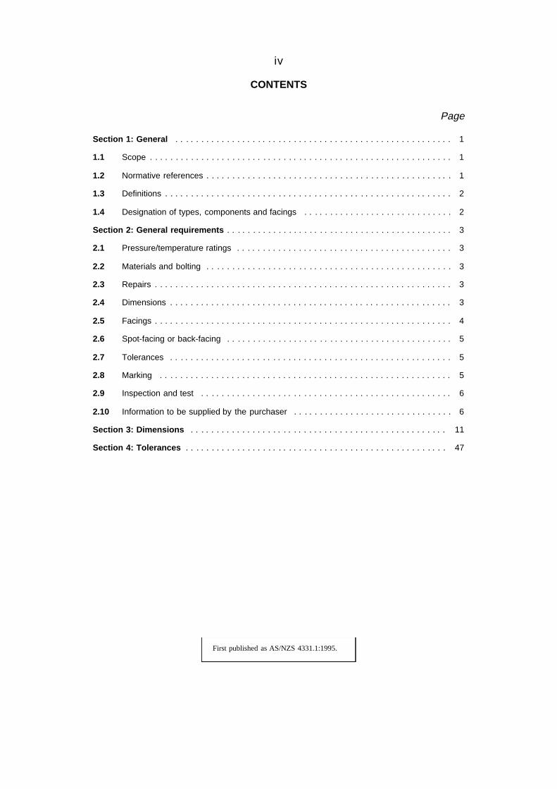
CONTENTS
Page
Section 1: General . . . . . . . . . . . . . . . . . . . . . . . . . . . . . . . . . . . . . . . . . . . . . . . . . . . . . . 1
1.1 Scope . . . . . . . . . . . . . . . . . . . . . . . . . . . . . . . . . . . . . . . . . . . . . . . . . . . . . . . . . . . 1
1.2 Normative references . . . . . . . . . . . . . . . . . . . . . . . . . . . . . . . . . . . . . . . . . . . . . . . . 1
1.3 Definitions . . . . . . . . . . . . . . . . . . . . . . . . . . . . . . . . . . . . . . . . . . . . . . . . . . . . . . . . 2
1.4 Designation of types, components and facings . . . . . . . . . . . . . . . . . . . . . . . . . . . . . 2
Section 2: General requirements . . . . . . . . . . . . . . . . . . . . . . . . . . . . . . . . . . . . . . . . . . . . 3
2.1 Pressure/temperature ratings . . . . . . . . . . . . . . . . . . . . . . . . . . . . . . . . . . . . . . . . . . 3
2.2 Materials and bolting . . . . . . . . . . . . . . . . . . . . . . . . . . . . . . . . . . . . . . . . . . . . . . . . 3
2.3 Repairs . . . . . . . . . . . . . . . . . . . . . . . . . . . . . . . . . . . . . . . . . . . . . . . . . . . . . . . . . . 3
2.4 Dimensions . . . . . . . . . . . . . . . . . . . . . . . . . . . . . . . . . . . . . . . . . . . . . . . . . . . . . . . 3
2.5 Facings . . . . . . . . . . . . . . . . . . . . . . . . . . . . . . . . . . . . . . . . . . . . . . . . . . . . . . . . . . 4
2.6 Spot-facing or back-facing . . . . . . . . . . . . . . . . . . . . . . . . . . . . . . . . . . . . . . . . . . . . 5
2.7 Tolerances . . . . . . . . . . . . . . . . . . . . . . . . . . . . . . . . . . . . . . . . . . . . . . . . . . . . . . . 5
2.8 Marking . . . . . . . . . . . . . . . . . . . . . . . . . . . . . . . . . . . . . . . . . . . . . . . . . . . . . . . . . 5
2.9 Inspection and test . . . . . . . . . . . . . . . . . . . . . . . . . . . . . . . . . . . . . . . . . . . . . . . . . 6
2.10 Information to be supplied by the purchaser . . . . . . . . . . . . . . . . . . . . . . . . . . . . . . . 6
Section 3: Dimensions . . . . . . . . . . . . . . . . . . . . . . . . . . . . . . . . . . . . . . . . . . . . . . . . . . 11
Section 4: Tolerances . . . . . . . . . . . . . . . . . . . . . . . . . . . . . . . . . . . . . . . . . . . . . . . . . . . 47
First published as AS/NZS 4331.1:1995.
www.bzfxw.com
v
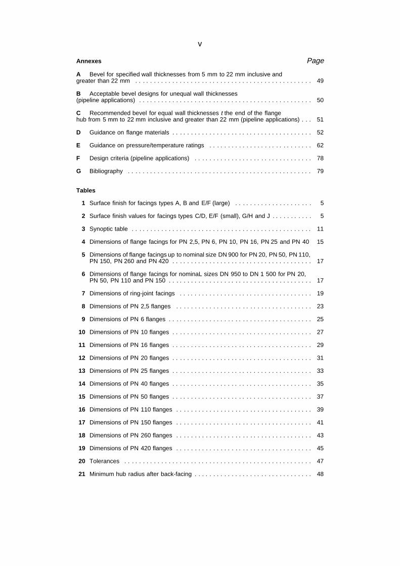
Annexes Page
A Bevel for specified wall thicknesses from 5 mm to 22 mm inclusive andgreater than 22 mm . . . . . . . . . . . . . . . . . . . . . . . . . . . . . . . . . . . . . . . . . . . . . . . . 49
B Acceptable bevel designs for unequal wall thicknesses(pipeline applications) . . . . . . . . . . . . . . . . . . . . . . . . . . . . . . . . . . . . . . . . . . . . . . . 50
C Recommended bevel for equal wall thicknesses t the end of the flangehub from 5 mm to 22 mm inclusive and greater than 22 mm (pipeline applications) . . . 51
D Guidance on flange materials . . . . . . . . . . . . . . . . . . . . . . . . . . . . . . . . . . . . . . 52
E Guidance on pressure/temperature ratings . . . . . . . . . . . . . . . . . . . . . . . . . . . . 62
F Design criteria (pipeline applications) . . . . . . . . . . . . . . . . . . . . . . . . . . . . . . . . 78
G Bibliography . . . . . . . . . . . . . . . . . . . . . . . . . . . . . . . . . . . . . . . . . . . . . . . . . . 79
Tables
1 Surface finish for facings types A, B and E/F (large) . . . . . . . . . . . . . . . . . . . . . 5
2 Surface finish values for facings types C/D, E/F (small), G/H and J . . . . . . . . . . . 5
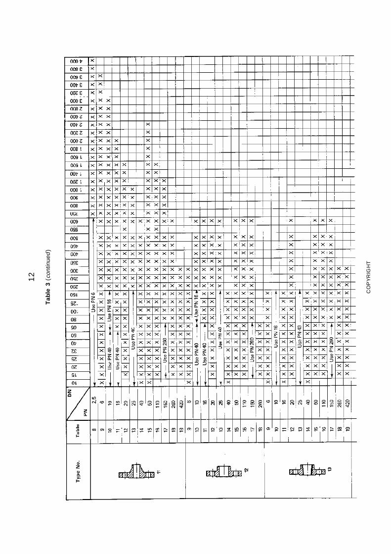
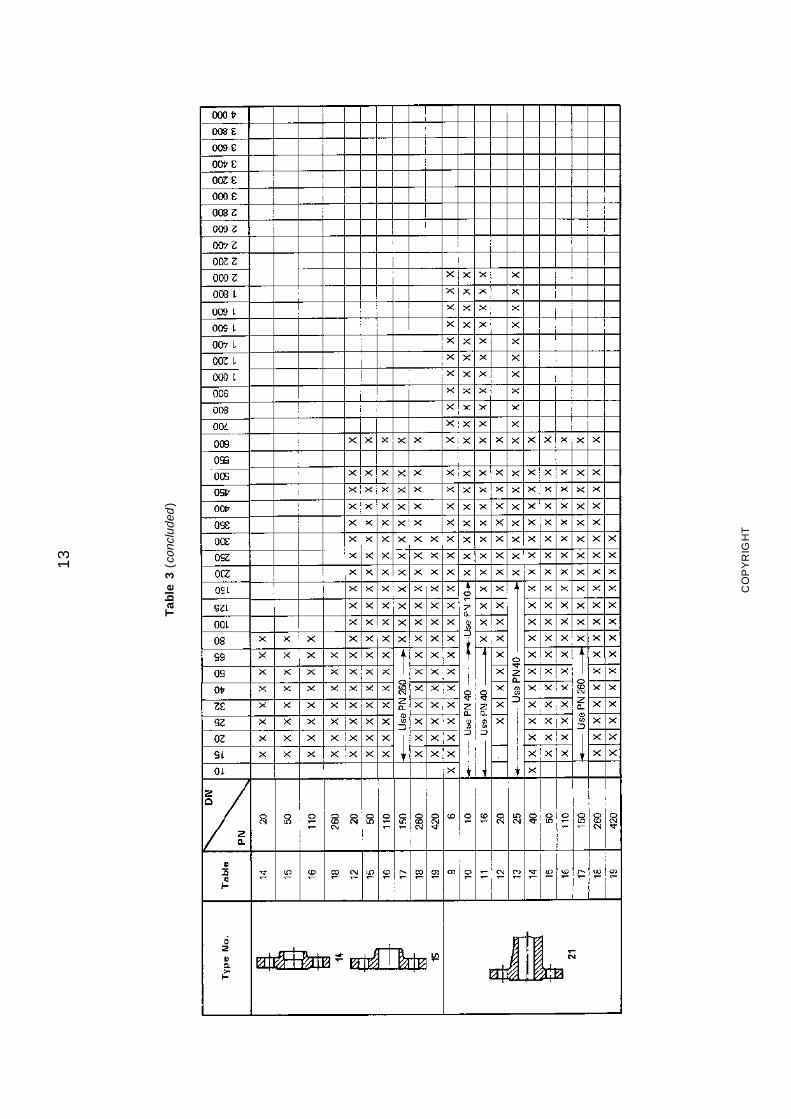
3 Synoptic table . . . . . . . . . . . . . . . . . . . . . . . . . . . . . . . . . . . . . . . . . . . . . . . . . 11
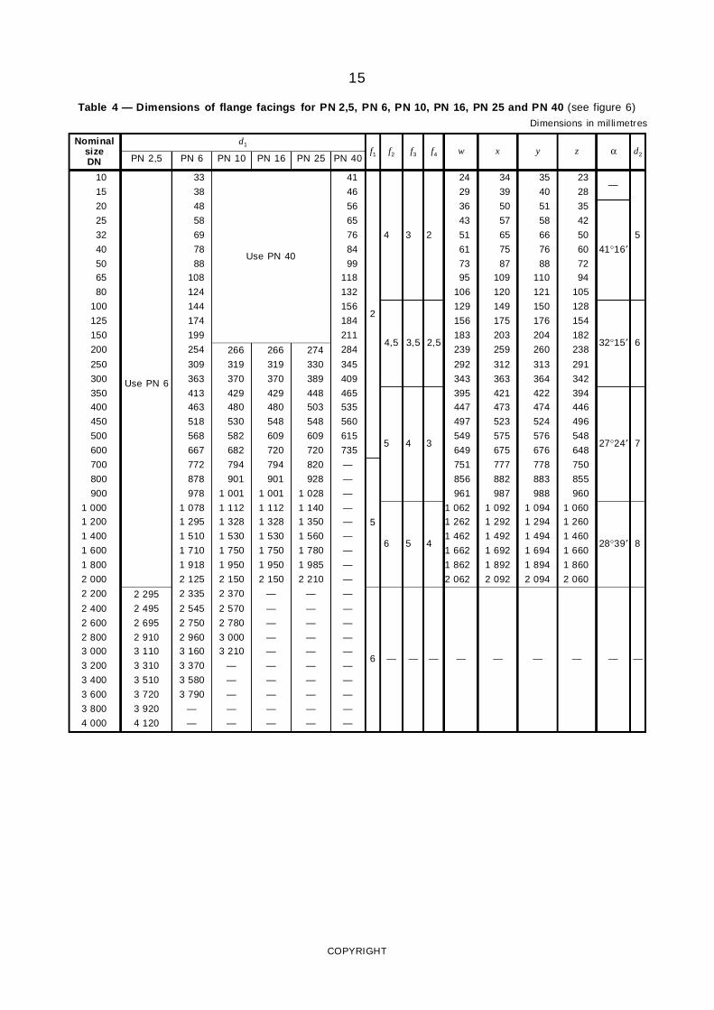
4 Dimensions of flange facings for PN 2,5, PN 6, PN 10, PN 16, PN 25 and PN 40 15
5 Dimensions of flange facings up to nominal size DN 900 for PN 20, PN 50, PN 110,PN 150, PN 260 and PN 420 . . . . . . . . . . . . . . . . . . . . . . . . . . . . . . . . . . . . . . 17
6 Dimensions of flange facings for nominaL sizes DN 950 to DN 1 500 for PN 20,PN 50, PN 110 and PN 150 . . . . . . . . . . . . . . . . . . . . . . . . . . . . . . . . . . . . . . . 17
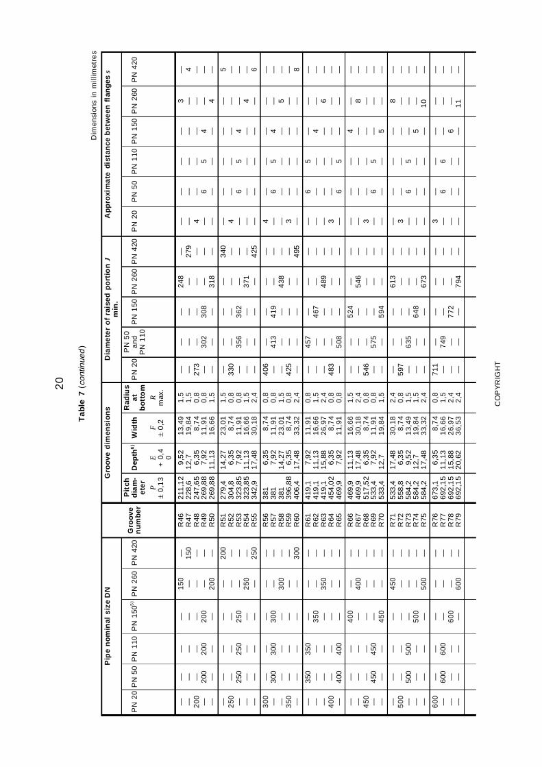
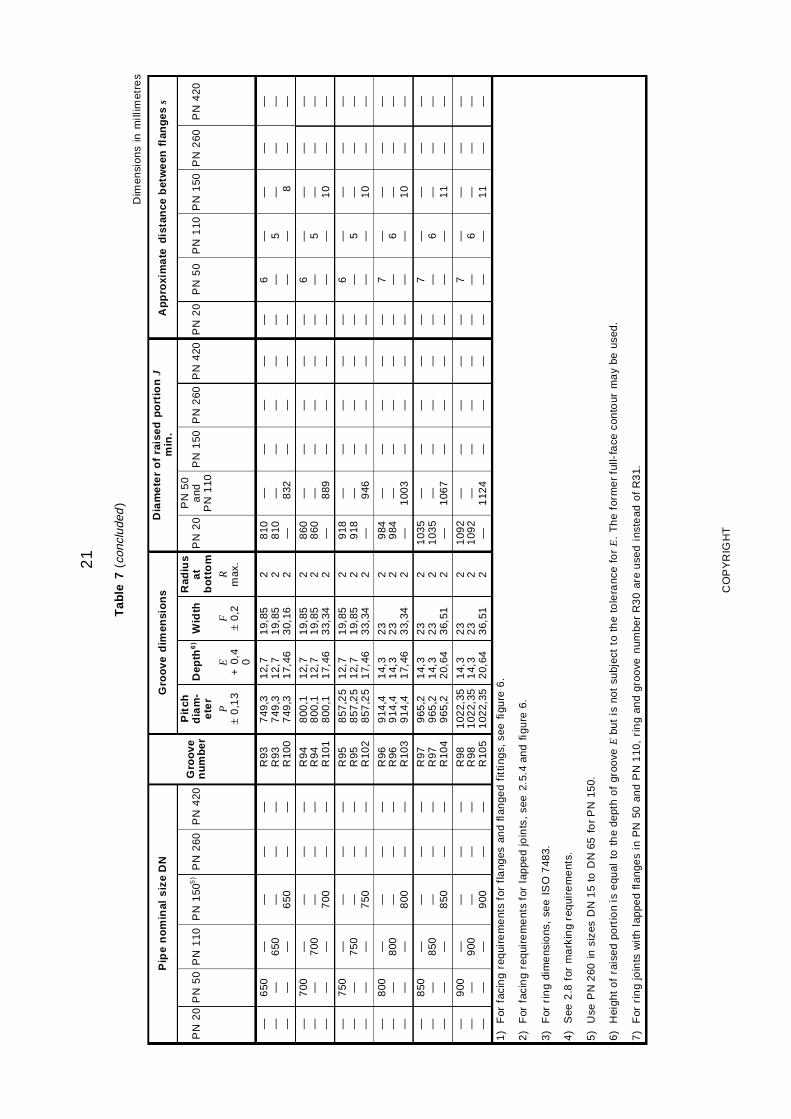
7 Dimensions of ring-joint facings . . . . . . . . . . . . . . . . . . . . . . . . . . . . . . . . . . . . 19
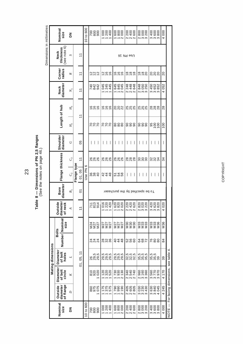
8 Dimensions of PN 2,5 flanges . . . . . . . . . . . . . . . . . . . . . . . . . . . . . . . . . . . . . 23
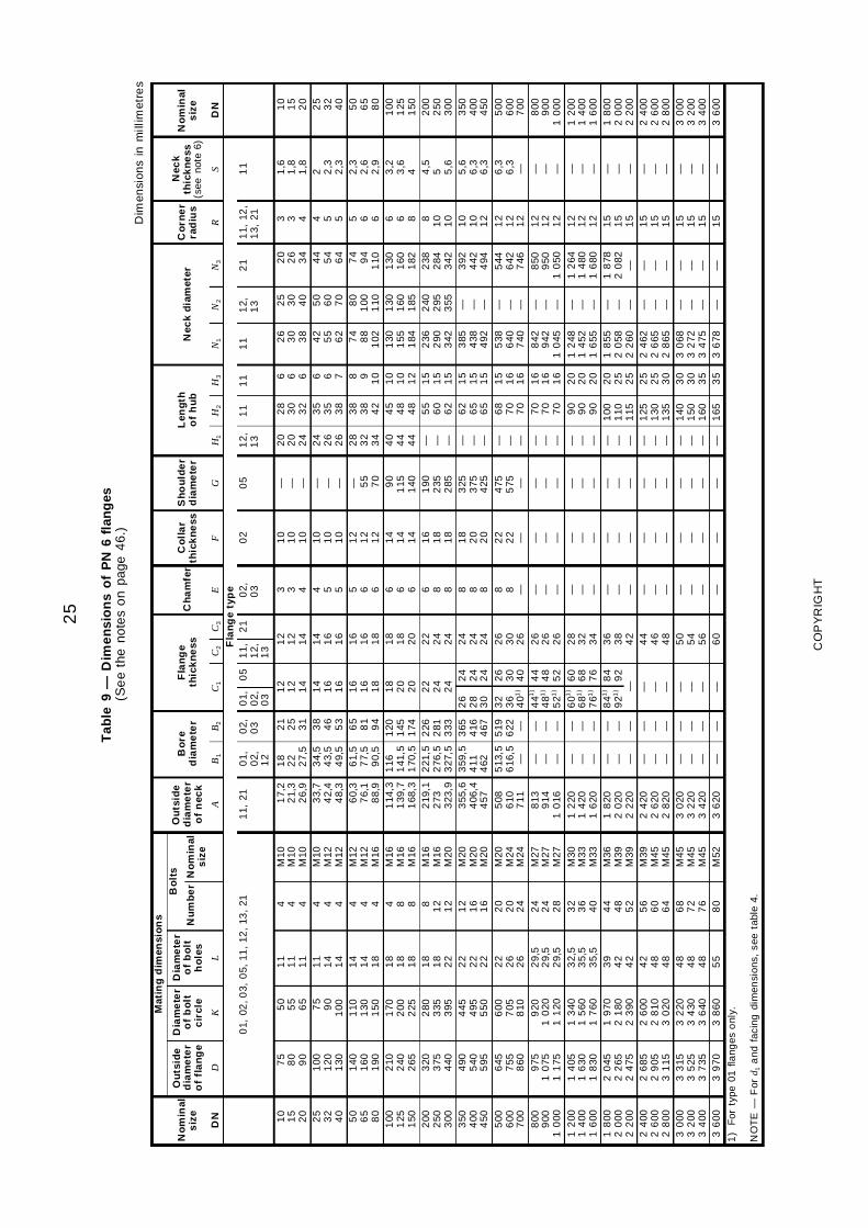
9 Dimensions of PN 6 flanges . . . . . . . . . . . . . . . . . . . . . . . . . . . . . . . . . . . . . . . 25
10 Dimensions of PN 10 flanges . . . . . . . . . . . . . . . . . . . . . . . . . . . . . . . . . . . . . . 27
11 Dimensions of PN 16 flanges . . . . . . . . . . . . . . . . . . . . . . . . . . . . . . . . . . . . . . 29
12 Dimensions of PN 20 flanges . . . . . . . . . . . . . . . . . . . . . . . . . . . . . . . . . . . . . . 31
13 Dimensions of PN 25 flanges . . . . . . . . . . . . . . . . . . . . . . . . . . . . . . . . . . . . . . 33
14 Dimensions of PN 40 flanges . . . . . . . . . . . . . . . . . . . . . . . . . . . . . . . . . . . . . . 35
15 Dimensions of PN 50 flanges . . . . . . . . . . . . . . . . . . . . . . . . . . . . . . . . . . . . . . 37
16 Dimensions of PN 110 flanges . . . . . . . . . . . . . . . . . . . . . . . . . . . . . . . . . . . . . 39
17 Dimensions of PN 150 flanges . . . . . . . . . . . . . . . . . . . . . . . . . . . . . . . . . . . . . 41
18 Dimensions of PN 260 flanges . . . . . . . . . . . . . . . . . . . . . . . . . . . . . . . . . . . . . 43
19 Dimensions of PN 420 flanges . . . . . . . . . . . . . . . . . . . . . . . . . . . . . . . . . . . . . 45
20 Tolerances . . . . . . . . . . . . . . . . . . . . . . . . . . . . . . . . . . . . . . . . . . . . . . . . . . . 47
21 Minimum hub radius after back-facing . . . . . . . . . . . . . . . . . . . . . . . . . . . . . . . . 48
vi
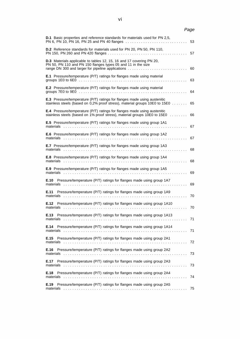
Page
D.1 Basic properties and reference standards for materials used for PN 2,5,PN 6, PN 10, PN 16, PN 25 and PN 40 flanges . . . . . . . . . . . . . . . . . . . . . . . . . . . . 53
D.2 Reference standards for materials used for PN 20, PN 50, PN 110,PN 150, PN 260 and PN 420 flanges . . . . . . . . . . . . . . . . . . . . . . . . . . . . . . . . . . . . 57
D.3 Materials applicable to tables 12, 15, 16 and 17 covering PN 20,PN 50, PN 110 and PN 150 flanges types 05 and 11 in the sizerange DN 300 and larger for pipeline applications . . . . . . . . . . . . . . . . . . . . . . . . . . . 60
E.1 Pressure/temperature (P/T) ratings for flanges made using materialgroups 1E0 to 6E0 . . . . . . . . . . . . . . . . . . . . . . . . . . . . . . . . . . . . . . . . . . . . . . . . . 63
E.2 Pressure/temperature (P/T) ratings for flanges made using materialgroups 7E0 to 9E0 . . . . . . . . . . . . . . . . . . . . . . . . . . . . . . . . . . . . . . . . . . . . . . . . . 64
E.3 Pressure/temperature (P/T) ratings for flanges made using austeniticstainless steels (based on 0,2% proof stress), material groups 10E0 to 15E0 . . . . . . . 65
E.4 Pressure/temperature (P/T) ratings for flanges made using austeniticstainless steels (based on 1% proof stress), material groups 10E0 to 15E0 . . . . . . . . 66
E.5 Pressure/temperature (P/T) ratings for flanges made using group 1A1materials . . . . . . . . . . . . . . . . . . . . . . . . . . . . . . . . . . . . . . . . . . . . . . . . . . . . . . . . 67
E.6 Pressure/temperature (P/T) ratings for flanges made using group 1A2materials . . . . . . . . . . . . . . . . . . . . . . . . . . . . . . . . . . . . . . . . . . . . . . . . . . . . . . . . 67
E.7 Pressure/temperature (P/T) ratings for flanges made using group 1A3materials . . . . . . . . . . . . . . . . . . . . . . . . . . . . . . . . . . . . . . . . . . . . . . . . . . . . . . . . 68
E.8 Pressure/temperature (P/T) ratings for flanges made using group 1A4materials . . . . . . . . . . . . . . . . . . . . . . . . . . . . . . . . . . . . . . . . . . . . . . . . . . . . . . . . 68
E.9 Pressure/temperature (P/T) ratings for flanges made using group 1A5materials . . . . . . . . . . . . . . . . . . . . . . . . . . . . . . . . . . . . . . . . . . . . . . . . . . . . . . . . 69
E.10 Pressure/temperature (P/T) ratings for flanges made using group 1A7materials . . . . . . . . . . . . . . . . . . . . . . . . . . . . . . . . . . . . . . . . . . . . . . . . . . . . . . . . 69
E.11 Pressure/temperature (P/T) ratings for flanges made using group 1A9materials . . . . . . . . . . . . . . . . . . . . . . . . . . . . . . . . . . . . . . . . . . . . . . . . . . . . . . . . 70
E.12 Pressure/temperature (P/T) ratings for flanges made using group 1A10materials . . . . . . . . . . . . . . . . . . . . . . . . . . . . . . . . . . . . . . . . . . . . . . . . . . . . . . . . 70
E.13 Pressure/temperature (P/T) ratings for flanges made using group 1A13materials . . . . . . . . . . . . . . . . . . . . . . . . . . . . . . . . . . . . . . . . . . . . . . . . . . . . . . . . 71
E.14 Pressure/temperature (P/T) ratings for flanges made using group 1A14materials . . . . . . . . . . . . . . . . . . . . . . . . . . . . . . . . . . . . . . . . . . . . . . . . . . . . . . . . 71
E.15 Pressure/temperature (P/T) ratings for flanges made using group 2A1materials . . . . . . . . . . . . . . . . . . . . . . . . . . . . . . . . . . . . . . . . . . . . . . . . . . . . . . . . 72
E.16 Pressure/temperature (P/T) ratings for flanges made using group 2A2materials . . . . . . . . . . . . . . . . . . . . . . . . . . . . . . . . . . . . . . . . . . . . . . . . . . . . . . . . 73
E.17 Pressure/temperature (P/T) ratings for flanges made using group 2A3materials . . . . . . . . . . . . . . . . . . . . . . . . . . . . . . . . . . . . . . . . . . . . . . . . . . . . . . . . 73
E.18 Pressure/temperature (P/T) ratings for flanges made using group 2A4materials . . . . . . . . . . . . . . . . . . . . . . . . . . . . . . . . . . . . . . . . . . . . . . . . . . . . . . . . 74
E.19 Pressure/temperature (P/T) ratings for flanges made using group 2A5materials . . . . . . . . . . . . . . . . . . . . . . . . . . . . . . . . . . . . . . . . . . . . . . . . . . . . . . . . 75
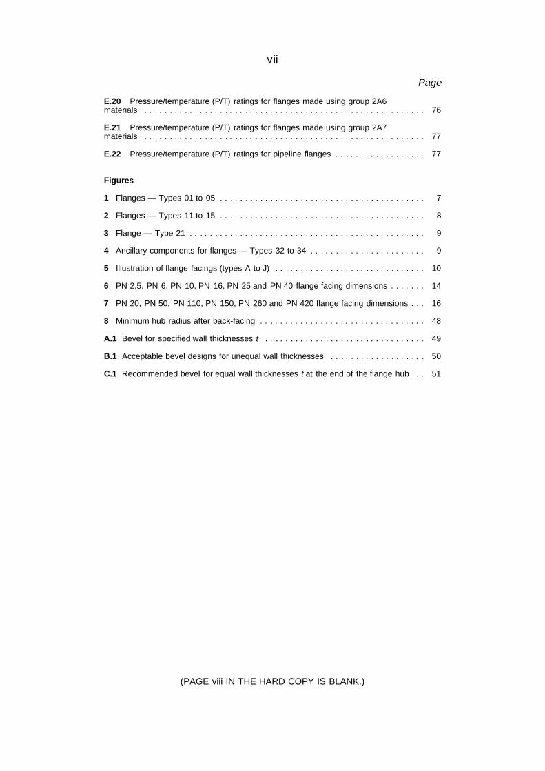
vii
Page
E.20 Pressure/temperature (P/T) ratings for flanges made using group 2A6materials . . . . . . . . . . . . . . . . . . . . . . . . . . . . . . . . . . . . . . . . . . . . . . . . . . . . . . . . 76
E.21 Pressure/temperature (P/T) ratings for flanges made using group 2A7materials . . . . . . . . . . . . . . . . . . . . . . . . . . . . . . . . . . . . . . . . . . . . . . . . . . . . . . . . 77
E.22 Pressure/temperature (P/T) ratings for pipeline flanges . . . . . . . . . . . . . . . . . . 77
Figures
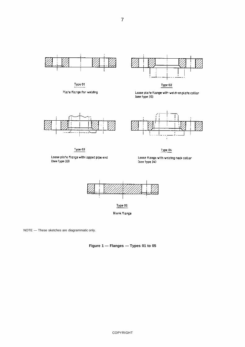
1 Flanges — Types 01 to 05 . . . . . . . . . . . . . . . . . . . . . . . . . . . . . . . . . . . . . . . . . 7
2 Flanges — Types 11 to 15 . . . . . . . . . . . . . . . . . . . . . . . . . . . . . . . . . . . . . . . . . 8
3 Flange — Type 21 . . . . . . . . . . . . . . . . . . . . . . . . . . . . . . . . . . . . . . . . . . . . . . . 9
4 Ancillary components for flanges — Types 32 to 34 . . . . . . . . . . . . . . . . . . . . . . . 9
5 Illustration of flange facings (types A to J) . . . . . . . . . . . . . . . . . . . . . . . . . . . . . . 10
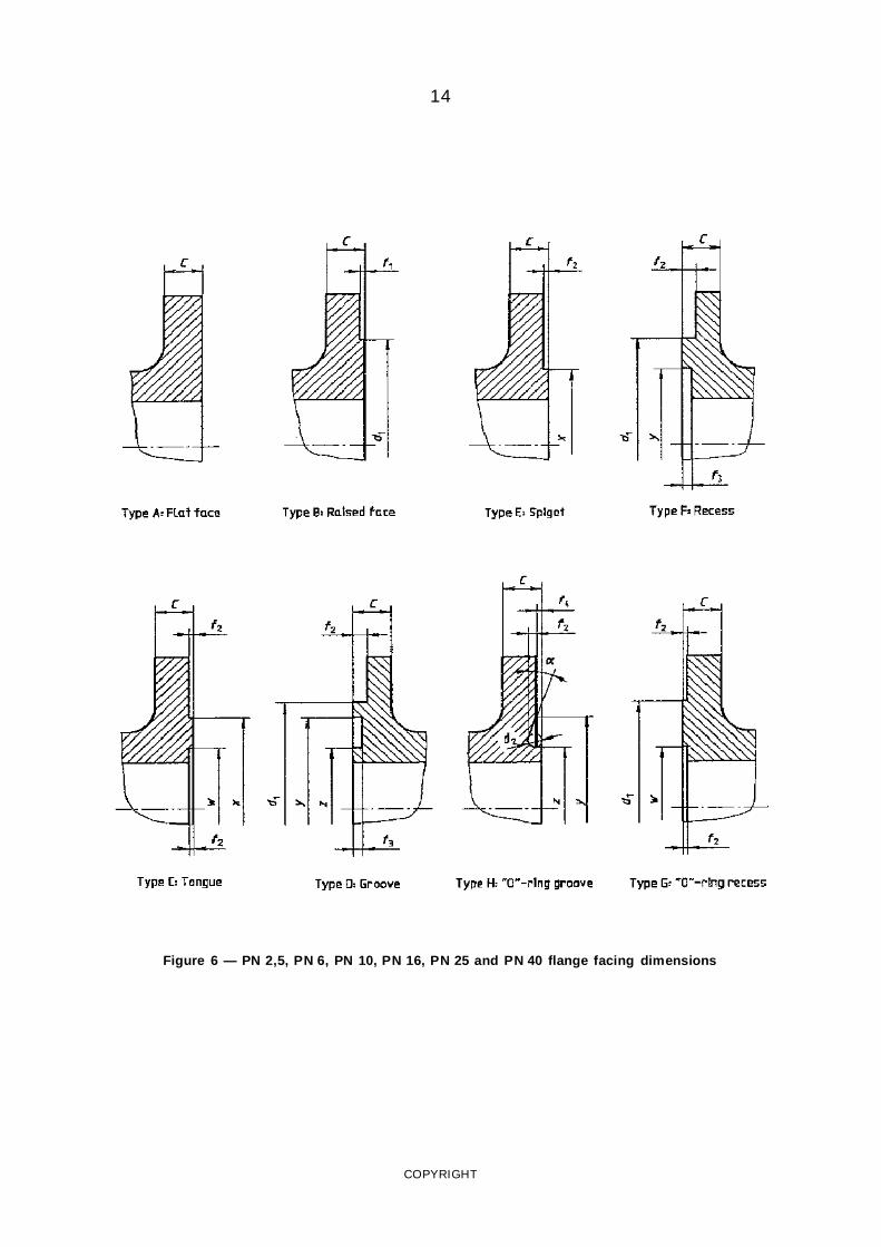
6 PN 2,5, PN 6, PN 10, PN 16, PN 25 and PN 40 flange facing dimensions . . . . . . . 14
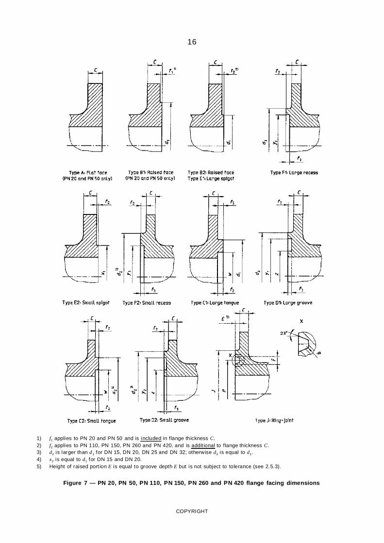
7 PN 20, PN 50, PN 110, PN 150, PN 260 and PN 420 flange facing dimensions . . . 16
8 Minimum hub radius after back-facing . . . . . . . . . . . . . . . . . . . . . . . . . . . . . . . . . 48
A.1 Bevel for specified wall thicknesses t . . . . . . . . . . . . . . . . . . . . . . . . . . . . . . . . 49
B.1 Acceptable bevel designs for unequal wall thicknesses . . . . . . . . . . . . . . . . . . . 50
C.1 Recommended bevel for equal wall thicknesses t at the end of the flange hub . . 51
(PAGE viii IN THE HARD COPY IS BLANK.)
1
AUSTRALIAN/NEW ZEALAND STANDARD
Metallic flanges —
Part 1:Steel flanges
Section 1: General
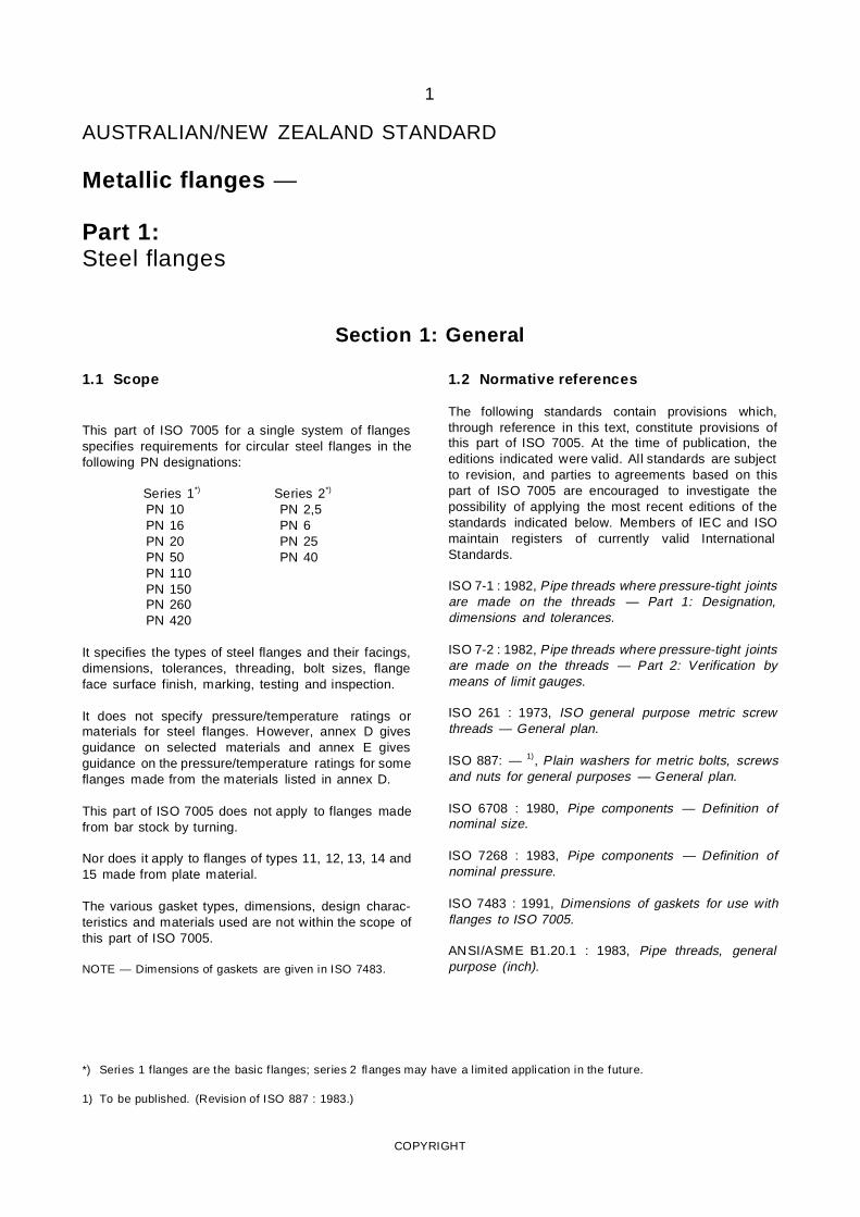
1.1 Scope
This part of ISO 7005 for a single system of flangesspecifies requirements for circular steel flanges in thefollowing PN designations:
Series 1*) Series 2*)
PN 10 PN 2,5PN 16 PN 6PN 20 PN 25PN 50 PN 40PN 110PN 150PN 260PN 420
It specifies the types of steel flanges and their facings,dimensions, tolerances, threading, bolt sizes, flangeface surface finish, marking, testing and inspection.
It does not specify pressure/temperature ratings ormaterials for steel flanges. However, annex D givesguidance on selected materials and annex E givesguidance on the pressure/temperature ratings for someflanges made from the materials listed in annex D.
This part of ISO 7005 does not apply to flanges madefrom bar stock by turning.
Nor does it apply to flanges of types 11, 12, 13, 14 and15 made from plate material.
The various gasket types, dimensions, design charac-teristics and materials used are not within the scope ofthis part of ISO 7005.
NOTE — Dimensions of gaskets are given in ISO 7483.
1.2 Normative references
The following standards contain provisions which,through reference in this text, constitute provisions ofthis part of ISO 7005. At the time of publication, theeditions indicated were valid. All standards are subjectto revision, and parties to agreements based on thispart of ISO 7005 are encouraged to investigate thepossibility of applying the most recent editions of thestandards indicated below. Members of IEC and ISOmaintain registers of currently valid InternationalStandards.
ISO 7-1 : 1982, Pipe threads where pressure-tight jointsare made on the threads — Part 1: Designation,dimensions and tolerances.
ISO 7-2 : 1982, Pipe threads where pressure-tight jointsare made on the threads — Part 2: Verification bymeans of limit gauges.
ISO 261 : 1973, ISO general purpose metric screwthreads — General plan.
ISO 887: — 1), Plain washers for metric bolts, screwsand nuts for general purposes — General plan.
ISO 6708 : 1980, Pipe components — Definition ofnominal size.
ISO 7268 : 1983, Pipe components — Definition ofnominal pressure.
ISO 7483 : 1991, Dimensions of gaskets for use withflanges to ISO 7005.
ANSI/ASME B1.20.1 : 1983, Pipe threads, generalpurpose (inch).
*) Series 1 flanges are the basic flanges; series 2 flanges may have a limited application in the future.
1) To be published. (Revision of ISO 887 : 1983.)
COPYRIGHT
2
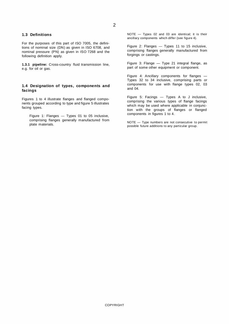
1.3 Definitions
For the purposes of this part of ISO 7005, the defini-tions of nominal size (DN) as given in ISO 6708, andnominal pressure (PN) as given in ISO 7268 and thefollowing definition apply.
1.3.1 pipeline: Cross-country fluid transmission line,e.g. for oil or gas.
1.4 Designation of types, components andfacings
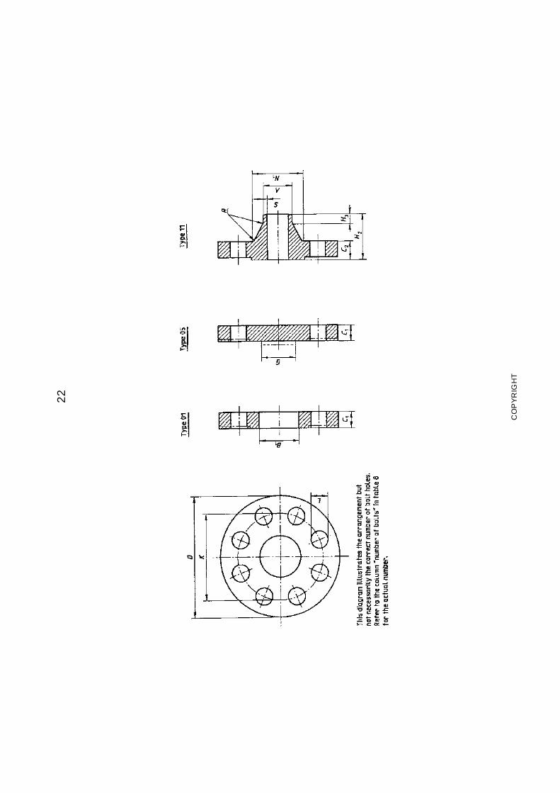
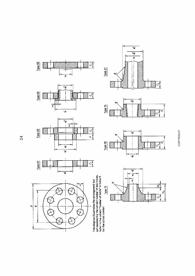
Figures 1 to 4 illustrate flanges and flanged compo-nents grouped according to type and figure 5 illustratesfacing types.
Figure 1: Flanges — Types 01 to 05 inclusive,comprising flanges generally manufactured fromplate materials.
NOTE — Types 02 and 03 are identical; it is theirancillary components which dif fer (see figure 4).
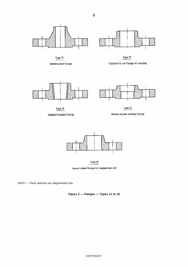
Figure 2: Flanges — Types 11 to 15 inclusive,comprising flanges generally manufactured fromforgings or castings.
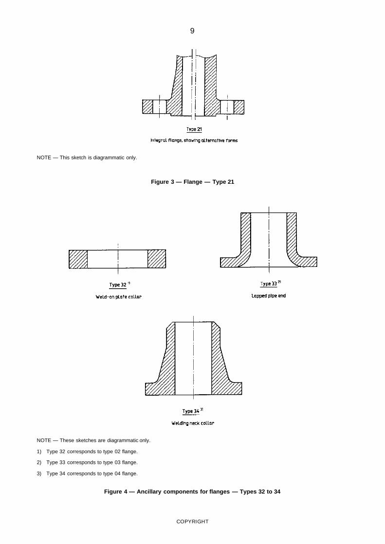
Figure 3: Flange — Type 21 integral flange, aspart of some other equipment or component.
Figure 4: Ancillary components for flanges —Types 32 to 34 inclusive, comprising parts orcomponents for use with flange types 02, 03and 04.
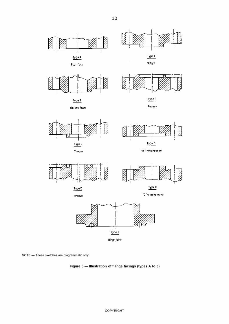
Figure 5: Facings — Types A to J inclusive,comprising the various types of flange facingswhich may be used where applicable in conjunc-tion with the groups of flanges or flangedcomponents in figures 1 to 4.
NOTE — Type numbers are not consecutive to permitpossible future addit ions to any part icular group.
COPYRIGHT
www.bzfxw.com
3
Section 2: General requirements
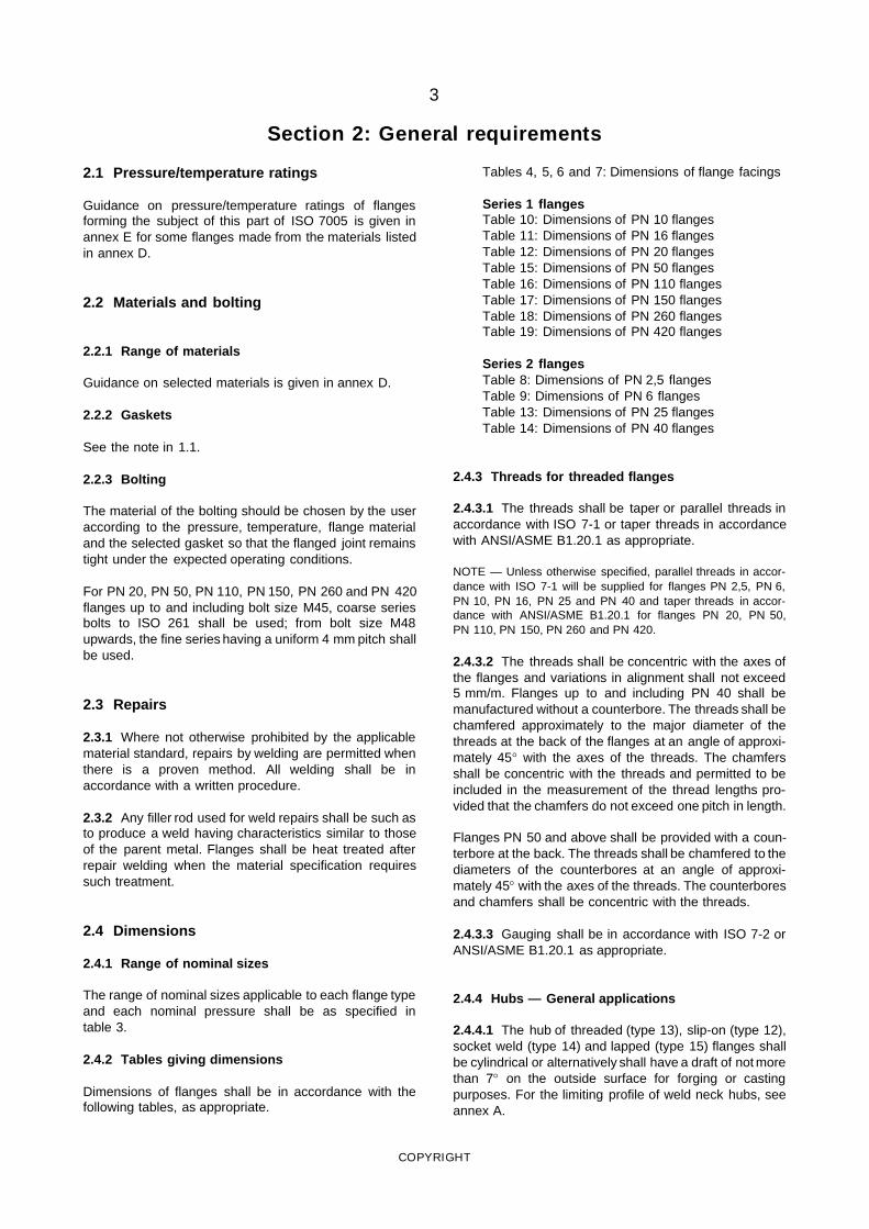
2.1 Pressure/temperature ratings
Guidance on pressure/temperature ratings of flangesforming the subject of this part of ISO 7005 is given inannex E for some flanges made from the materials listedin annex D.
2.2 Materials and bolting
2.2.1 Range of materials
Guidance on selected materials is given in annex D.
2.2.2 Gaskets
See the note in 1.1.
2.2.3 Bolting
The material of the bolting should be chosen by the useraccording to the pressure, temperature, flange materialand the selected gasket so that the flanged joint remainstight under the expected operating conditions.
For PN 20, PN 50, PN 110, PN 150, PN 260 and PN 420flanges up to and including bolt size M45, coarse seriesbolts to ISO 261 shall be used; from bolt size M48upwards, the fine series having a uniform 4 mm pitch shallbe used.
2.3 Repairs
2.3.1 Where not otherwise prohibited by the applicablematerial standard, repairs by welding are permitted whenthere is a proven method. All welding shall be inaccordance with a written procedure.
2.3.2 Any filler rod used for weld repairs shall be such asto produce a weld having characteristics similar to thoseof the parent metal. Flanges shall be heat treated afterrepair welding when the material specification requiressuch treatment.
2.4 Dimensions
2.4.1 Range of nominal sizes
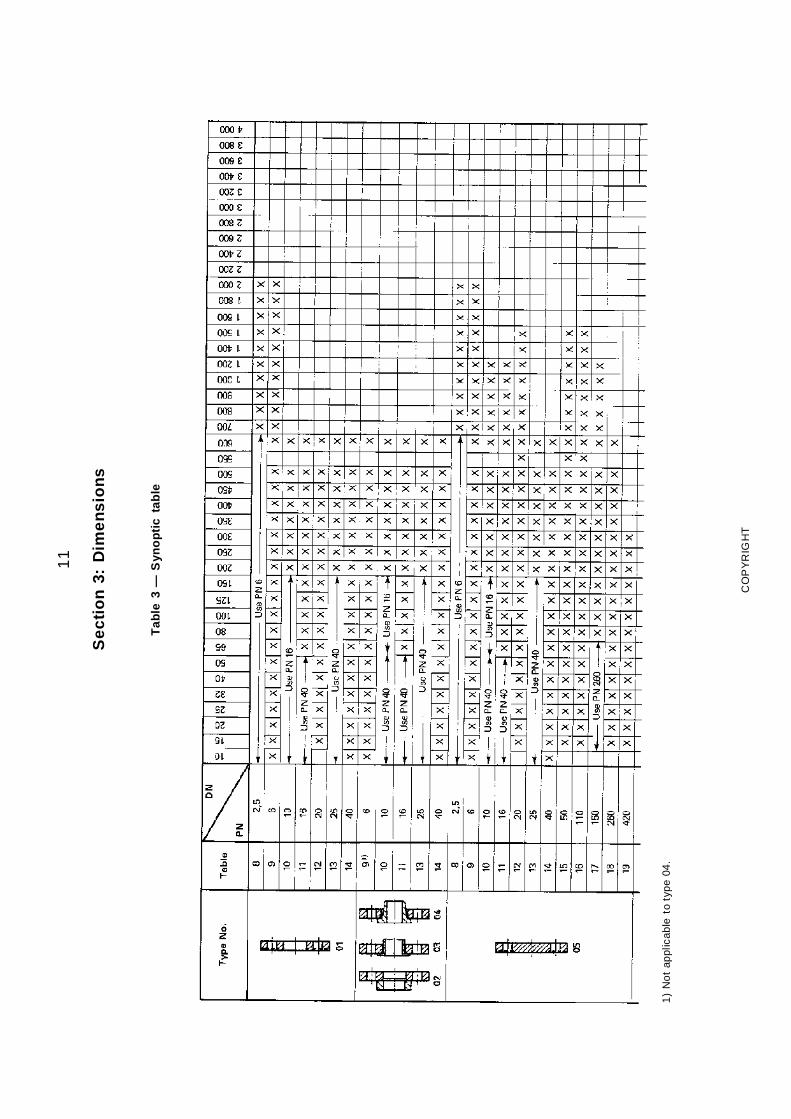
The range of nominal sizes applicable to each flange typeand each nominal pressure shall be as specified intable 3.
2.4.2 Tables giving dimensions
Dimensions of flanges shall be in accordance with thefollowing tables, as appropriate.
Tables 4, 5, 6 and 7: Dimensions of flange facings
Series 1 flangesTable 10: Dimensions of PN 10 flangesTable 11: Dimensions of PN 16 flangesTable 12: Dimensions of PN 20 flangesTable 15: Dimensions of PN 50 flangesTable 16: Dimensions of PN 110 flangesTable 17: Dimensions of PN 150 flangesTable 18: Dimensions of PN 260 flangesTable 19: Dimensions of PN 420 flanges
Series 2 flangesTable 8: Dimensions of PN 2,5 flangesTable 9: Dimensions of PN 6 flangesTable 13: Dimensions of PN 25 flangesTable 14: Dimensions of PN 40 flanges
2.4.3 Threads for threaded flanges
2.4.3.1 The threads shall be taper or parallel threads inaccordance with ISO 7-1 or taper threads in accordancewith ANSI/ASME B1.20.1 as appropriate.
NOTE — Unless otherwise specified, parallel threads in accor-dance with ISO 7-1 will be supplied for flanges PN 2,5, PN 6,PN 10, PN 16, PN 25 and PN 40 and taper threads in accor-dance with ANSI/ASME B1.20.1 for flanges PN 20, PN 50,PN 110, PN 150, PN 260 and PN 420.
2.4.3.2 The threads shall be concentric with the axes ofthe flanges and variations in alignment shall not exceed5 mm/m. Flanges up to and including PN 40 shall bemanufactured without a counterbore. The threads shall bechamfered approximately to the major diameter of thethreads at the back of the flanges at an angle of approxi-mately 45° with the axes of the threads. The chamfersshall be concentric with the threads and permitted to beincluded in the measurement of the thread lengths pro-vided that the chamfers do not exceed one pitch in length.
Flanges PN 50 and above shall be provided with a coun-terbore at the back. The threads shall be chamfered to thediameters of the counterbores at an angle of approxi-mately 45° with the axes of the threads. The counterboresand chamfers shall be concentric with the threads.
2.4.3.3 Gauging shall be in accordance with ISO 7-2 orANSI/ASME B1.20.1 as appropriate.
2.4.4 Hubs — General applications
2.4.4.1 The hub of threaded (type 13), slip-on (type 12),socket weld (type 14) and lapped (type 15) flanges shallbe cylindrical or alternatively shall have a draft of not morethan 7° on the outside surface for forging or castingpurposes. For the limiting profile of weld neck hubs, seeannex A.
COPYRIGHT
www.bzfxw.com
4
2.4.4.2 The hub dimensions of threaded (type 13) andslip-on (type 12) flanges having a reduced bore shall beat least as large as those of the standard flange of thesize to which the reduction is being made. For weldingneck (type 11) flanges having a reduced bore, the hubdimensions shall be the same as those of the standardflange of the size to which the reduction is being made.
2.4.5 Hubs — Pipeline applications
2.4.5.1 The hub diameter and wall thickness at thewelding end shall be determined as specified in 2.4.5.1.1to 2.4.5.1.3 as appropriate.
2.4.5.1.1 When the minimum yield strength of the hubportion of any flange or its representative test specimen isthe same as that of the mating pipe, the minimumthickness at the welding end shall be the same as that ofthe mating pipe.
2.4.5.1.2 When the minimum yield strength of the hubportion of any flange or its representative test specimen isless than that specified for the pipe to be matched, theminimum thickness of the hub at the welding end shall besuch that the product of its thickness times its yieldstrength (at the welding end) shall at least equal theproduct of the specified wall thickness and the minimumspecified yield strength of the pipe to be matched.
2.4.5.1.3 When the hub thickness at the welding end isgreater than the wall thickness of the adjoining pipe, thejoint design shall be as shown in any of the three sketchesin figure B.1.
2.4.5.2 The minimum hub outside diameter at the point ofweld shall be determined by adding twice the minimumwall thickness determined in 2.4.5.1.1 or 2.4.5.1.2 to thebore specified by the customer.
2.4.5.3 For sizes DN 300 to DN 600, when the mechani-cal (minimum yield strength) properties of all sections ofthe flanges are equal to or higher than those of the pipeto be matched, the hub dimensions are permitted to bethe same as those of the general flanges as indicated inannex A.
2.4.6 Welding end preparation
For welding type 11 flanges to pipe, the typical endpreparation of the flange shall be as shown in annex A.When PN 20, PN 50, PN 110 and PN 150 flanges areused in pipeline applications the typical welding endpreparations are as shown in annex C.
NOTE — Other welding end preparations agreed between manu-facturer and purchaser do not invalidate compliance with this partof ISO 7005.
2.5 Facings
2.5.1 Range of facings
The range of flange facings and flange face designationsshall be as given in figure 5. Dimensions of facings accor-ding to the PN designation shall be in accordance withfigures 6 and 7 and tables 4, 5, 6 and 7, as appropriate.
NOTES
1 For types B (as shown in figure 6 only), D, F, G and J thetransition from the raised face diameter to the flange face is atthe option of the manufacturer.
2 For PN 20 and PN 50 to PN 420 there are large and small ver-sions of C, D, E and F types of facing. In such cases two sets ofdimensions have been given in the related tables. For small maleand female joints care should be taken to ensure that the insidediameter of the pipe is small enough to permit sufficient bearingsurface.
3 The type B raised face on steel flanges may be removed whenbolted to cast iron or copper alloy flanges for designations up toand including PN 50 in order to provide full-face gasketing if suchbe required. On a flanged component or fitting this will reduce thethickness and the overall length accordingly.
2.5.2 Facing height/depth
For PN 2,5, PN 6, PN 10, PN 16, PN 25 and PN 40flanges all facing heights shall be included in the minimumflange thickness and are measured from the face of theflange. The same requirement applies for PN 20 andPN 50 flanges when they have the (type B1) raised face.For PN 20, PN 50, PN 110, PN 150, PN 260 and PN 420flanges with other facings, e.g. type B2, spigot and recess,tongue and groove, the height or depth shall be added tothe minimum flange thickness. For PN 110 to PN 420flanges all facings shall be added to the minimum flangethickness. Special requirements apply to ring-joint facings(see 2.5.3).
2.5.3 Ring-joint facings
The bottom of the ring-joint groove shall not encroachbelow the plane of the flange edge of the appropriateminimum thickness flange. Where the depth of the ring-type joint groove would violate this requirement, sufficientmetal shall be added to the flange thickness or raised faceheight so that the bottom of the groove shall be in thesame plane as the flange edge of a minimum thicknessflange.
2.5.4 Lapped joints
For type 33 ancillary components for flanges, the finishedheight of the facing shall be not less than the pipethickness used. If a tongue, groove or ring-joint face isrequired, the thickness of the lap remaining aftermachining the facing shall not be less than the specifiedthickness of the pipe used.
2.5.5 Surface finish of flanges
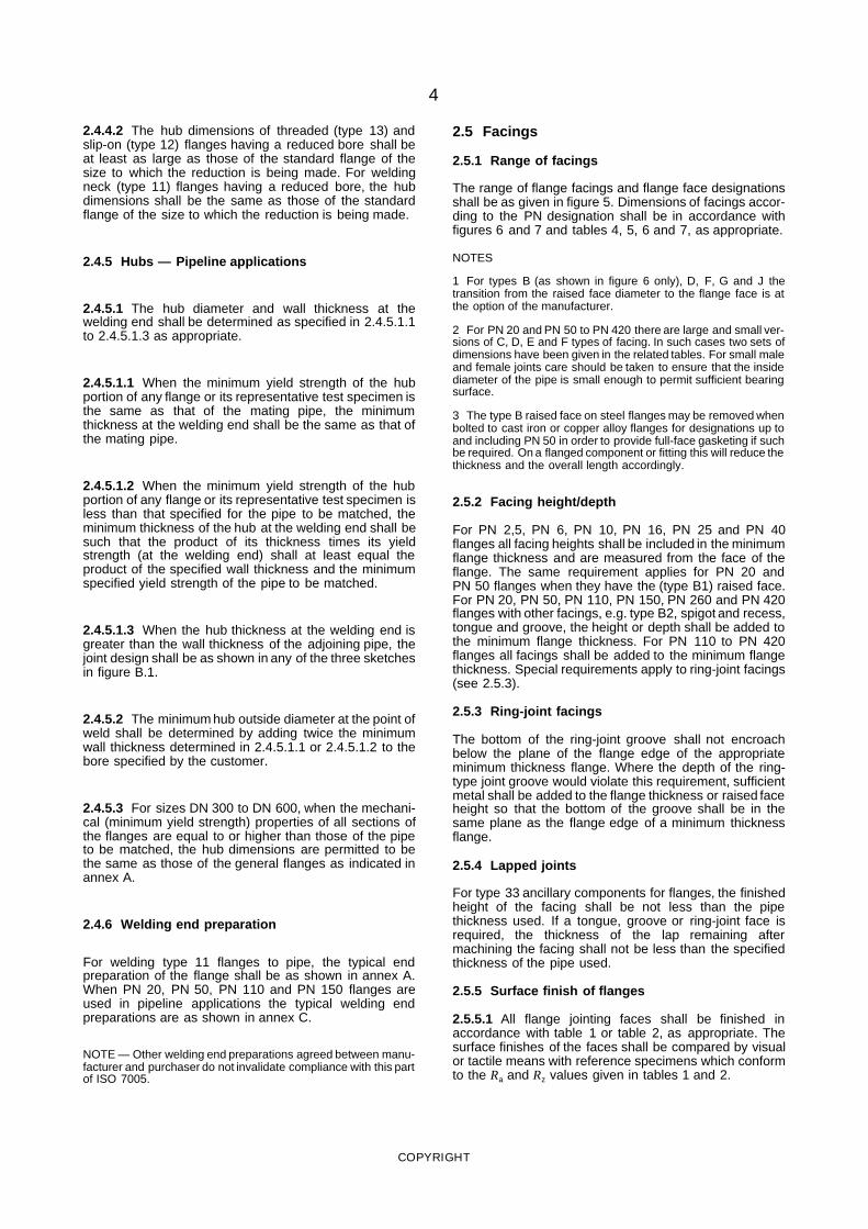
2.5.5.1 All flange jointing faces shall be finished inaccordance with table 1 or table 2, as appropriate. Thesurface finishes of the faces shall be compared by visualor tactile means with reference specimens which conformto the Ra and Rz values given in tables 1 and 2.
COPYRIGHT
www.bzfxw.com
5
Table 1 — Surface finish for facings types A, B and E/F (large)
Method ofmachining
Approximatedepth ofserration
mm
Approximateradius oftool nose
mm
Approximatepitch of
serrationmm
Rz1)
μmRa
1)
μm
min. max. min. max.
Turning2) 0,05 1,6 0,8 12,5 50,0 3,2 12,5
Other thanturning
— — — 12,5 25,0 3,2 6,3
1) Ra and Rz are defined in ISO 468.
2) The term “turning” includes any method of machine operation producing either serrated concentric orserrated spiral grooves.
NOTE — For certain applications, e.g. for searching media such as low temperature gases, and forflanges of PN 150 and above, it may be necessary to stipulate closer control on the surface finish.
NOTES
1 It is not intended that instrument measurements are taken onthe flange faces, and the Ra and Rz values as defined in ISO 468relate to the reference specimens.
2 Other finishes may be agreed between the manufacturer andpurchaser.
2.5.5.2 The dimensions given for facings (particularlytongue and groove types] in this part of ISO 7005 apply toflanges in the condition as delivered.
When special coatings or finishes are required this shouldbe stated in the order so that an appropriate allowancemay be incorporated in the machining of any relevantmating dimensions.
2.5.5.3 Flat face, raised face and large spigot/recessfacings [i.e. types A, B and E/F (large)] shall be turned.Turning shall be carried out with a round-nosed tool inaccordance with table 1.
2.5.5.4 For tongue/groove, small spigot/recess, “O”-ringrecess/groove and ring-joint facings [i.e. types C/D, E/F(small), G/H and J] the gasket surfaces shall be machinedin accordance with the values shown in table 2.
Table 2 — Surface finish values for facingstypes C/D, E/F (small), G/H and J
Facing typeRz
1)
μmRa
1)
μm
min. max. min. max.
Tongue/groove (C/D) and smallspigot/recess (E/F)
3,2 12,5 0,8 3,2
Ring-joint (J) ( including side walls)and “O”- ring recess/groove (G/H)
1,6 6,3 0,4 1,6
1) Ra and Rz are defined in ISO 468.
2.6 Spot-facing or back-facing
Any spot-facing or back-facing required shall not reducethe flange thickness to less than the thickness specified.
When spot-facing is used, the diameter shall be largeenough to accommodate the outside diameter of theequivalent normal series of ISO washers complying withISO 887 for the metric bolt size being fitted. When aflange is back-faced, it is permissible for the fillet radius tobe reduced but it shall not be eliminated entirely. Thebearing surfaces for the bolting shall be parallel to theflange face within the limits shown in table 20.
When a flange is back-faced a minimum fillet radius at thehub, Rmin (see figure 8), shall be maintained as given intable 21.
2.7 Tolerances
Flange dimensions shall comply with the tolerancesspecified in table 20.
2.8 Marking
2.8.1 Flanges other than integral flanges
Flanges other than integral flanges shall be marked withthe following information:
a) the number of this part of ISO 7005 (i.e.ISO 7005-1);b) the nominal size (DN) and the PN designation;c) the material designation (see 2.8.2);d) the manufacturer’s name or trade-mark;e) the thread identification where appropriate(see 2.8.3);f) the heat (cast) number or suitable quality controlnumber traceable to the heat number.
NOTES1 Additionally, flange facing designations may be given (seealso 2.8.4).2 Where a flange is subsequently used to form an integral partof a component and the component has a lower pressure ratingthan that of the flange, the lower rating should be clearly markedon the component.
2.8.2 Material designation
The material designation shall be as specified in 2.8.2.1,2.8.2.2 and 2.8.2.3, as appropriate.
COPYRIGHT
www.bzfxw.com
6
2.8.2.1 The material designation shall be the minimuminformation required to identify the material, e.g. the gradeidentification, preceded by the specification (standard)number where necessary.
EXAMPLES (for materials in tables D.1 and D.2)
a) 16Mo3
b) C26-52H
c) X7 CrNiNb 18 10
2.8.2.2 For flanges of nominal size DN 300 and greater,manufactured specifically for pipeline applications, thematerial designation shall be the material group and gradeidentification number in accordance with table D.3.
EXAMPLE
4.A.250
2.8.2.3 For flanges manufactured in accordance with2.4.5.1.2, the material designation shall comprise thematerial group and grade identification number for theflange and the strength grade of the pipe for which theflange has been made, presented as shown in thefollowing example.
EXAMPLE
4.A.290/XXX
where XXX is the strength grade of the pipe, taken fromthe appropriate steel tube standard.
2.8.3 Identification of internally threaded flanges
Internally threaded flanges shall be marked to indicate thetype of thread used.
Threads to ISO 7-1 shall be designated by the lettersymbols Rc or Rp, as appropriate, in accordance withISO 7-1 followed by the nominal size, e.g. Rc 3/4.Threads to ANSI/ASME B1.20.1 shall be designated bythe nominal size, number of threads per inch and theletters NPT, e.g. 3/4-14NPT.
2.8.4 Groove number
Flanges grooved for standard ring-joints shall be markedwith the letter “R” and the corresponding ring number.
2.8.5 Stamping
Where steel stamps are used, the marking shall beapplied to the rim of the flange.
2.9 Inspection and test
NOTES
1 The PN 20, PN 50, PN 110, PN 150, PN 260 and PN 420flanges specified are designed to be interchangeable with Classrated flanges to ANSI/ASME B16.5 and MSS 5P44, but they arenot identical in all respects; for inspection purposes, it isrecommended that the dimensions of PN 20, PN 50, PN 110,PN 150, PN 260 and PN 420 flanges are deemed to comply withthe dimensions specified in ANSI/ASME B16.5 or MSS 5P44 asappropriate.
2 This part of ISO 7005 does not make provision for routineinspection or pressure testing of separate flanges. However,flanges may be required to be pressure tested after attachmentof a pipe or other equipment or when forming an integral part ofsuch equipment. The test pressure is then dependent on therequirements of the appropriate standard or code of practice inaccordance with which the equipment has been manufactured.Any test pressures should not exceed 1,5 times the maximumallowable working pressure at 20°C rounded off to the next higher1 bar1) increment.
2.10 Information to be supplied by thepurchaser
The following information should be supplied by thepurchaser in the enquiry and/or order:
a) the number of this part of ISO 7005 (i.e.ISO 7005-1);
b) the nominal size — DN followed by the appropriatenumber (see 1.3);
c) the PN designation — PN followed by theappropriate number (see 1.3);
d) the flange type number (see 1.4), together withreference to the ancillary component type number ifappropriate;
e) the facing type letter (see 1.4);
f) the material designation by reference to a nationalstandard or International Standard and grade of steel(see 2.8.2), if appropriate;
g) the internal thread designation (see 2.4.3);
h) the external diameter and thickness of pipe;
i) material certification requirements;
j) details of special coatings (see 2.5.5.2);
k) the neck thickness S where appropriate;
i) the bore diameter B where appropriate;
m) the bore diameter for welding neck (type 11) orsocket weld (type 14) flanges, if different from thosespecified in this part of ISO 7005;
n) for pipeline flanges, the mating pipe wall thicknessand yield strength (see 2.4.5.1.3) and weld preparation(see annex B);
o) the bolting material when bolts are ordered with theflange(s).
1) 1 bar = 105 Pa
COPYRIGHT
www.bzfxw.com
7
NOTE — These sketches are diagrammatic only.
Figure 1 — Flanges — Types 01 to 05
COPYRIGHT
www.bzfxw.com
8
NOTE — These sketches are diagrammatic only.
Figure 2 — Flanges — Types 11 to 15
COPYRIGHT
www.bzfxw.com
9
NOTE — This sketch is diagrammatic only.
Figure 3 — Flange — Type 21
NOTE — These sketches are diagrammatic only.
1) Type 32 corresponds to type 02 flange.
2) Type 33 corresponds to type 03 flange.
3) Type 34 corresponds to type 04 flange.
Figure 4 — Ancillary components for flanges — Types 32 to 34
COPYRIGHT
www.bzfxw.com
10
NOTE — These sketches are diagrammatic only.
Figure 5 — Illustration of flange facings (types A to J)
COPYRIGHT
www.bzfxw.com11
Se
cti
on
3:D
ime
nsi
on
s
Tab
le3
—S
yno
pti
cta
ble
1)
No
tap
plic
able
toty
pe
04.
CO
PY
RIG
HT
www.bzfxw.com12
Tab
le3
(con
tinue
d)
CO
PY
RIG
HT
www.bzfxw.com13
Tab
le3
(con
clud
ed)
CO
PY
RIG
HT
www.bzfxw.com
14
Figure 6 — PN 2,5, PN 6, PN 10, PN 16, PN 25 and PN 40 flange facing dimensions
COPYRIGHT
www.bzfxw.com
15
Table 4 — Dimensions of flange facings for PN 2,5, PN 6, PN 10, PN 16, PN 25 and PN 40 (see figure 6)Dimensions in mil limetres
NominalsizeDN
d1f1 f2 f3 f4 w x y z α d2PN 2,5 PN 6 PN 10 PN 16 PN 25 PN 40
10
Use PN 6
33
Use PN 40
41
2
4 3 2
24 34 35 23—
5
15 38 46 29 39 40 28
20 48 56 36 50 51 35
41°16′
25 58 65 43 57 58 42
32 69 76 51 65 66 50
40 78 84 61 75 76 60
50 88 99 73 87 88 7265 108 118 95 109 110 94
80 124 132 106 120 121 105
100 144 156
4,5 3,5 2,5
129 149 150 128
32°15′ 6
125 174 184 156 175 176 154
150 199 211 183 203 204 182
200 254 266 266 274 284 239 259 260 238
250 309 319 319 330 345 292 312 313 291
300 363 370 370 389 409 343 363 364 342
350 413 429 429 448 465
5 4 3
395 421 422 394
27°24′ 7
400 463 480 480 503 535 447 473 474 446
450 518 530 548 548 560 497 523 524 496
500 568 582 609 609 615 549 575 576 548
600 667 682 720 720 735 649 675 676 648
700 772 794 794 820 —
5
751 777 778 750
800 878 901 901 928 — 856 882 883 855
900 978 1 001 1 001 1 028 — 961 987 988 960
1 000 1 078 1 112 1 112 1 140 —
6 5 4
1 062 1 092 1 094 1 060
28°39′ 8
1 200 1 295 1 328 1 328 1 350 — 1 262 1 292 1 294 1 260
1 400 1 510 1 530 1 530 1 560 — 1 462 1 492 1 494 1 460
1 600 1 710 1 750 1 750 1 780 — 1 662 1 692 1 694 1 660
1 800 1 918 1 950 1 950 1 985 — 1 862 1 892 1 894 1 860
2 000 2 125 2 150 2 150 2 210 — 2 062 2 092 2 094 2 060
2 200 2 295 2 335 2 370 — — —
6 — — — — — — — — —
2 400 2 495 2 545 2 570 — — —
2 600 2 695 2 750 2 780 — — —
2 800 2 910 2 960 3 000 — — —3 000 3 110 3 160 3 210 — — —
3 200 3 310 3 370 — — — —
3 400 3 510 3 580 — — — —
3 600 3 720 3 790 — — — —
3 800 3 920 — — — — —
4 000 4 120 — — — — —
COPYRIGHT
www.bzfxw.com
16
1) f1 applies to PN 20 and PN 50 and is included in flange thickness C.2) f2 applies to PN 110, PN 150, PN 260 and PN 420, and is addit ional to flange thickness C.3) d2 is larger than d1 for DN 15, DN 20, DN 25 and DN 32; otherwise d2 is equal to d1.4) x2 is equal to d1 for DN 15 and DN 20.5) Height of raised port ion E is equal to groove depth E but is not subject to tolerance (see 2.5.3).
Figure 7 — PN 20, PN 50, PN 110, PN 150, PN 260 and PN 420 flange facing dimensions
COPYRIGHT
www.bzfxw.com
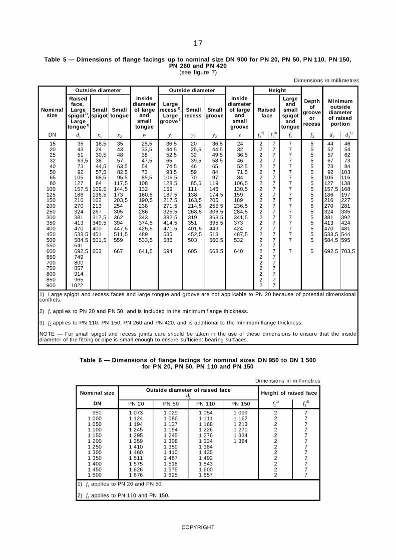
17
Table 5 — Dimensions of flange facings up to nominal size DN 900 for PN 20, PN 50, PN 110, PN 150,PN 260 and PN 420
(see figure 7)Dimensions in mil limetres
Outside diameter Outside diameter Height
Nominalsize
Raisedface,Large
spigot1),Large
tongue1)
Smallspigot
Smalltongue
Insidediameterof large
andsmall
tongue
Largerecess 1),
Largegroove 1)
Smallrecess
Smallgroove
Insidediameterof large
andsmall
groove
Raisedface
Largeand
smallspigot
andtongue
Depthof
grooveor
recess
Minimumoutside
diameterof raisedportion
DN d1 x1 x2 w y1 y3 y2 z f12) f2
3) f2 f3 d2 d31)
1520253240506580
100125150200250300350400450500550600650700750800850900
35435163,57392
105127157,5186216270324381413470533,5584,5641692,5749800857914965
1022
18,52430,53844,557,568,584
109,5136,5162213267317,5349,5400451501,5
603
3543485763,582,595,5
117,5144,5173203,5254305362394447,5511,5559
667
25,533,53847,5547385,5
108132160,5190,5238286343374,5425,5489533,5
641,5
36,544,552,56574,593,5
106,5128,5159187,5217,5271,5325,5382,5414,5471,5535586
694
2025,53239,546597085,5
111138163,5214,5268,5319351401,5452,5503
605
36,544,549,558,5658497
119146174,5205255,5306,5363,5395,5449513560,5
668,5
243236,54652,571,584
106,5130,5159189236,5284,5341,5373424487,5532
640
22222222222222222222222222
77777777777777777777777777
777777777777777777
7
555555555555555555
5
445257677392
105127157,5186216270324381413470533,5584,5
692,5
4654627384
103116138168197227281335392424481544595
703,5
1) Large spigot and recess faces and large tongue and groove are not applicable to PN 20 because of potential dimensionalconflicts.
2) f1 applies to PN 20 and PN 50, and is included in the minimum flange thickness.
3) f2 applies to PN 110, PN 150, PN 260 and PN 420, and is addit ional to the minimum flange thickness.
NOTE — For small spigot and recess joints care should be taken in the use of these dimensions to ensure that the insidediameter of the fit ting or pipe is small enough to ensure suff icient bearing surfaces.
Table 6 — Dimensions of flange facings for nominal sizes DN 950 to DN 1 500for PN 20, PN 50, PN 110 and PN 150
Dimensions in mil limetres
Nominal size Outside diameter of raised faced1
Height of raised face
DN PN 20 PN 50 PN 110 PN 150 f11) f2
2)
9501 0001 0501 1001 1501 2001 2501 3001 3501 4001 4501 500
1 0731 1241 1941 2451 2951 3591 4101 4601 5111 5751 6261 676
1 0291 0861 1371 1941 2451 3081 3591 4101 4671 5181 5751 625
1 0541 1111 1681 2261 2761 3341 3841 4351 4921 5431 6001 657
1 0991 1621 2131 2701 3341 384
222222222222
777777777777
1) f1 applies to PN 20 and PN 50.
2) f2 applies to PN 110 and PN 150.
COPYRIGHT
www.bzfxw.com18
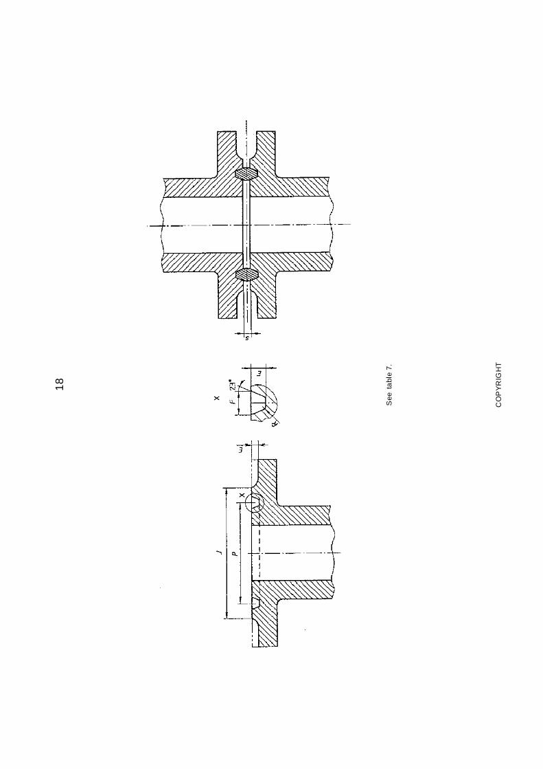
See
tabl
e7.
CO
PY
RIG
HT
www.bzfxw.com19
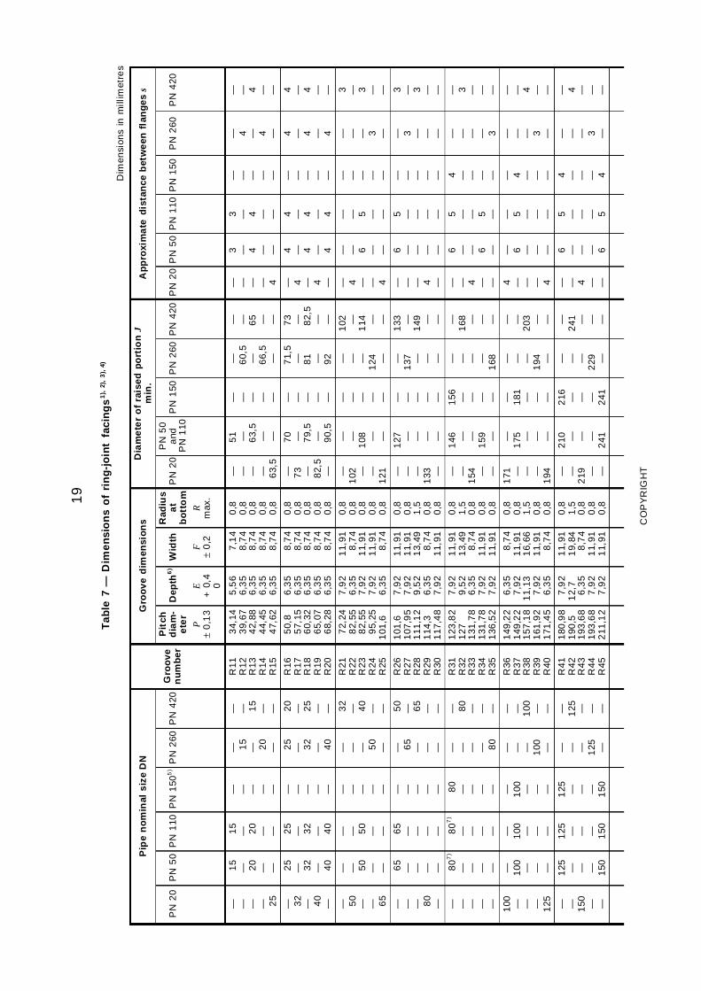
Tab
le7
—D
imen
sio
ns
of
rin
g-j
oin
tfa
cin
gs
1),
2),
3),
4)
Dim
ensi
ons
inm
illim
etre
s
Pip
en
om
inal
siz
eD
NG
roo
ved
imen
sio
ns
Dia
me
ter
of
rais
edp
ort
ion
Jm
in.
Ap
pro
xim
ate
dis
tan
ceb
etw
een
flan
ges
s
PN
20
PN
50
PN
110
PN
150
5)
PN
260
PN
420
Gro
ove
nu
mb
er
Pit
chd
iam
-e
ter
Dep
th6
)W
idth
Rad
ius
at
bo
tto
mP
N2
0P
N5
0a
ndP
N1
10P
N1
50P
N2
60P
N4
20P
N2
0P
N5
0P
N1
10P
N1
50P
N2
60P
N4
20
P±
0,1
3E
+0,
40
F±
0,2
Rm
ax.
— — — — 25
15
— 20
— —
15
— 20
— —
— — — — —
— 15
— 20
—
— — 15
— —
R11
R12
R13
R14
R15
34,
143
9,67
42,
884
4,45
47,
62
5,5
66
,35
6,3
56
,35
6,3
5
7,1
48
,74
8,7
48
,74
8,7
4
0,8
0,8
0,8
0,8
0,8
— — — — 63,
5
51 — 63,
5— —
— — — — —
— 60,
5— 66,
5—
— — 65 — —
— — — — 4
3 — 4 — —
3 — 4 — —
— — — — —
— 4 — 4 —
— — 4 — —
— 32
— 40
—
25
— 32
— 40
25
— 32
— 40
— — — — —
25
— 32
— 40
20
— 25
— —
R16
R17
R18
R19
R20
50,
85
7,15
60,
326
5,07
68,
28
6,3
56
,35
6,3
56
,35
6,3
5
8,7
48
,74
8,7
48
,74
8,7
4
0,8
0,8
0,8
0,8
0,8
— 73 — 82,
5—
70 — 79,
5— 90,
5
— — — — —
71,
5— 81 — 92
73 — 82,
5— —
— 4 — 4 —
4 — 4 — 4
4 — 4 — 4
— — — — —
4 — 4 — 4
4 — 4 — —
— 50
— — 65
— — 50
— —
— — 50
— —
— — — — —
— — — 50
—
32
— 40
— —
R21
R22
R23
R24
R25
72,
248
2,55
82,
559
5,25
101
,6
7,9
26
,35
7,9
27
,92
6,3
5
11,
918
,74
11,
911
1,91
8,7
4
0,8
0,8
0,8
0,8
0,8
—1
02 — —1
21
— —1
08 — —
— — — — —
— — —1
24 —
102 —
114 — —
— 4 — — 4
— — 6 — —
— — 5 — —
— — — — —
— — — 3 —
3 — 3 — —
— — — 80
—
65
— — — —
65
— — — —
— — — — —
— 65
— — —
50
— 65
— —
R26
R27
R28
R29
R30
101
,61
07,9
51
11,1
21
14,3
117
,48
7,9
27
,92
9,5
26
,35
7,9
2
11,
911
1,91
13,
498
,74
11,
91
0,8
0,8
1,5
0,8
0,8
— — —1
33 —
127 — — — —
— — — — —
—1
37 — — —
133 —
149 — —
— — — 4 —
6 — — — —
5 — — — —
— — — — —
— 3 — — —
3 — 3 — —
— — — — —
80
7)
— — — —
80
7)
— — — —
80
— — — —
— — — — 80
— 80
— — —
R31
R32
R33
R34
R35
123
,82
127
131
,78
131
,78
136
,52
7,9
29
,52
6,3
57
,92
7,9
2
11,
911
3,49
8,7
41
1,91
11,
91
0,8
1,5
0,8
0,8
0,8
— —1
54 — —
146 — —
159 —
156 — — — —
— — — —1
68
—1
68 — — —
— — 4 — —
6 — — 6 —
5 — — 5 —
4 — — — —
— — — — 3
— 3 — — —
100 — — — 125
— 100 — — —
— 100 — — —
— 100 — — —
— — — 100 —
— — 100 — —
R36
R37
R38
R39
R40
149
,22
149
,22
157
,18
161
,92
171
,45
6,3
57
,92
11,
137
,92
6,3
5
8,7
41
1,91
16,
661
1,91
8,7
4
0,8
0,8
1,5
0,8
0,8
171 — — —
194
—1
75 — — —
— 181 — — —
— — —1
94 —
— —2
03 — —
4 — — — 4
— 6 — — —
— 5 — — —
— 4 — — —
— — — 3 —
— — 4 — —
— — 150 — —
125 — — — 150
125 — — — 150
125 — — — 150
— — — 125 —
— 125 — — —
R41
R42
R43
R44
R45
180
,98
190
,51
93,6
81
93,6
82
11,1
2
7,9
21
2,7
6,3
57
,92
7,9
2
11,
911
9,84
8,7
41
1,91
11,
91
0,8
1,5
0,8
0,8
0,8
— —2
19 — —
210 — — —
241
216 — — — 241
— — —2
29 —
—2
41 — — —
— — 4 — —
6 — — — 6
5 — — — 5
4 — — — 4
— — — 3 —
— 4 — — —
CO
PY
RIG
HT
www.bzfxw.com20
Tab
le7
(con
tinue
d)
Dim
ensi
ons
inm
illim
etre
s
Pip
en
om
inal
siz
eD
NG
roo
ved
imen
sio
ns
Dia
me
ter
of
rais
edp
ort
ion
Jm
in.
Ap
pro
xim
ate
dis
tan
ceb
etw
een
flan
ges
s
PN
20
PN
50
PN
110
PN
150
5)
PN
260
PN
420
Gro
ove
nu
mb
er
Pit
chd
iam
-e
ter
Dep
th6
)W
idth
Rad
ius
at
bo
tto
mP
N2
0P
N5
0a
ndP
N1
10P
N1
50P
N2
60P
N4
20P
N2
0P
N5
0P
N1
10P
N1
50P
N2
60P
N4
20
P±
0,1
3E
+0,
40
F±
0,2
Rm
ax.
— — 200 — —
— — — 200 —
— — — 200 —
— — — 200 —
150 — — — 200
— 150 — — —
R46
R47
R48
R49
R50
211
,12
228
,62
47,6
52
69,8
82
69,8
8
9,5
21
2,7
6,3
57
,92
11,
13
13,
491
9,84
8,7
41
1,91
16,
66
1,5
1,5
0,8
0,8
1,5
— — 273 — —
— — — 302 —
— — — 308 —
248 — — — 318
— 279 — — —
— — 4 — —
— — — 6 —
— — — 5 —
— — — 4 —
3 — — — 4
— 4 — — —
— 250 — — —
— — 250 — —
— — 250 — —
— — 250 — —
— — — 250 —
200 — — — 250
R51
R52
R53
R54
R55
279
,43
04,8
323
,85
323
,85
342
,9
14,
276
,35
7,9
21
1,13
17,
48
23,
018
,74
11,
911
6,66
30,
18
1,5
0,8
0,8
1,5
2,4
— 330 — — —
— — 356 — —
— — 362 — —
— — — 371 —
340 — — — 425
— 4 — — —
— — 6 — —
— — 5 — —
— — 4 — —
— — — 4 —
5 — — — 6
300 — — 350 —
— 300 — — —
— 300 — — —
— 300 — — —
— — 300 — —
— — — — 300
R56
R57
R58
R59
R60
381
381
381
396
,88
406
,4
6,3
57
,92
14,
276
,35
17,
48
8,7
41
1,91
23,
018
,74
33,
32
0,8
0,8
1,5
0,8
2,4
406 — — 425 —
— 413 — — —
— 419 — — —
— — 438 — —
— — — — 495
4 — — 3 —
— 6 — — —
— 5 — — —
— 4 — — —
— — 5 — —
— — — — 8
— — — 400 —
350 — — — 400
350 — — — 400
— 350 — — —
— — 350 — —
— — — — —
R61
R62
R63
R64
R65
419
,14
19,1
419
,14
54,0
24
69,9
7,9
21
1,13
15,
886
,35
7,9
2
11,
911
6,66
26,
978
,74
11,
91
0,8
1,5
2,4
0,8
0,8
— — — 483 —
457 — — — 508
— 467 — — —
— — 489 — —
— — — — —
— — — 3 —
6 — — — 6
5 — — — 5
— 4 — — —
— — 6 — —
— — — — —
— — 450 — —
— — — 450 —
— — — 450 —
400 — — — 450
— 400 — — —
— — — — —
R66
R67
R68
R69
R70
469
,94
69,9
517
,52
533
,45
33,4
11,
131
7,48
6,3
57
,92
12,
7
16,
663
0,18
8,7
41
1,91
19,
84
1,5
2,4
0,8
0,8
1,5
— — 546 — —
— — — 575 —
524 — — — 594
— 546 — — —
— — — — —
— — 3 — —
— — — 6 —
— — — 5 —
4 — — — 5
— 8 — — —
— — — — —
— 500 — — —
— — 500 — —
— — 500 — —
— — — 500 —
450 — — — 500
— — — — —
R71
R72
R73
R74
R75
533
,45
58,8
584
,25
84,2
584
,2
17,
486
,35
9,5
21
2,7
17,
48
30,
188
,74
13,
491
9,84
33,
32
2,4
0,8
1,5
1,5
2,4
— 597 — — —
— — 635 — —
— — — 648 —
613 — — — 673
— — — — —
— 3 — — —
— — 6 — —
— — 5 — —
— — — 5 —
8 — — — 10
— — — — —
600 — — —
— 600 — —
— 600 — —
— — 600 —
— — — 600
— — — —
R76
R77
R78
R79
673
,16
92,1
56
92,1
56
92,1
5
6,3
51
1,13
15,
882
0,62
8,7
41
6,66
26,
973
6,53
0,8
1,5
2,4
2,4
711 — — —
— 749 — —
— — 772 —
— — — 794
— — — —
3 — — —
— 6 — —
— 6 — —
— — 6 —
— — — 11
— — — —
CO
PY
RIG
HT
www.bzfxw.com21
Tab
le7
(con
clud
ed)
Dim
ensi
ons
inm
illim
etre
s
Pip
en
om
inal
siz
eD
NG
roo
ved
imen
sio
ns
Dia
me
ter
of
rais
edp
ort
ion
Jm
in.
Ap
pro
xim
ate
dis
tan
ceb
etw
een
flan
ges
s
PN
20
PN
50
PN
110
PN
150
5)
PN
260
PN
420
Gro
ove
nu
mb
er
Pit
chd
iam
-e
ter
Dep
th6
)W
idth
Rad
ius
at
bo
tto
mP
N2
0P
N5
0a
ndP
N1
10P
N1
50P
N2
60P
N4
20P
N2
0P
N5
0P
N1
10P
N1
50P
N2
60P
N4
20
P±
0,1
3E
+0,
40
F±
0,2
Rm
ax.
— — —
650 — —
— 650 —
— — 650
— — —
— — —
R93
R93
R10
0
749
,37
49,3
749
,3
12,
71
2,7
17,
46
19,
851
9,85
30,
16
2 2 2
810
810 —
— — 832
— — —
— — —
— — —
— — —
6 — —
— 5 —
— — 8
— — —
— — —
— — —
700 — —
— 700 —
— — 700
— — —
— — —
R94
R94
R10
1
800
,18
00,1
800
,1
12,
71
2,7
17,
46
19,
851
9,85
33,
34
2 2 2
860
860 —
— — 889
— — —
— — —
— — —
— — —
6 — —
— 5 —
— — 10
— — —
— — —
— — —
750 — —
— 750 —
— — 750
— — —
— — —
R95
R95
R10
2
857
,25
857
,25
857
,25
12,
71
2,7
17,
46
19,
851
9,85
33,
34
2 2 2
918
918 —
— — 946
— — —
— — —
— — —
— — —
6 — —
— 5 —
— — 10
— — —
— — —
— — —
800 — —
— 800 —
— — 800
— — —
— — —
R96
R96
R10
3
914
,49
14,4
914
,4
14,
31
4,3
17,
46
23
23
33,
34
2 2 2
984
984 —
— —1
003
— — —
— — —
— — —
— — —
7 — —
— 6 —
— — 10
— — —
— — —
— — —
850 — —
— 850 —
— — 850
— — —
— — —
R97
R97
R10
4
965
,29
65,2
965
,2
14,
31
4,3
20,
64
23
23
36,
51
2 2 2
103
51
035
—
— —1
067
— — —
— — —
— — —
— — —
7 — —
— 6 —
— — 11
— — —
— — —
— — —
900 — —
— 900 —
— — 900
— — —
— — —
R98
R98
R10
5
102
2,35
102
2,35
102
2,35
14,
31
4,3
20,
64
23
23
36,
51
2 2 2
109
21
092
—
— —1
124
— — —
— — —
— — —
— — —
7 — —
— 6 —
— — 11
— — —
— — —
1)
For
faci
ng
req
uire
me
nts
for
fla
nges
and
flan
ged
fitt
ing
s,se
efi
gure
6.
2)
For
faci
ng
req
uire
me
nts
for
lap
ped
join
ts,
see
2.5.
4an
dfi
gure
6.
3)
For
rin
gdi
me
nsio
ns,
see
ISO
748
3.
4)
See
2.8
for
ma
rkin
gre
qui
rem
ent
s.
5)
Use
PN
260
insi
zes
DN
15
toD
N65
for
PN
150.
6)
Hei
ght
of
rais
ed
port
ion
ise
qual
toth
ede
pth
of
groo
veE
but
isno
tsu
bjec
tto
the
tole
ranc
efo
rE
.T
he
form
er
full-
face
con
tour
ma
ybe
used
.
7)
For
rin
gjo
ints
with
lap
ped
flan
ges
inP
N50
and
PN
110
,ri
ng
and
groo
ven
umbe
rR
30
are
use
din
ste
ado
fR
31.
CO
PY
RIG
HT
www.bzfxw.com22
CO
PY
RIG
HT
www.bzfxw.com23
Tab
le8
—D
imen
sio
ns
of
PN
2,5
flan
ges
(Se
eth
eno
tes
on
page
46.
)
Dim
ensi
ons
inm
illim
etre
s
Mat
ing
dim
en
sio
ns
No
min
als
ize
Ou
tsid
ed
iam
ete
ro
ffl
ang
e
Dia
me
ter
of
bo
ltc
ircl
e
Dia
me
ter
of
bo
lth
ole
s
Bo
lts
Ou
tsid
ed
iam
ete
ro
fn
eck
Bo
red
iam
ete
rF
lan
ge
thic
knes
sS
ho
uld
erd
iam
ete
rL
eng
tho
fh
ub
Nec
kd
iam
ete
rC
orn
erra
diu
s
Nec
kth
ickn
ess
(se
en
ote
6)
No
min
als
ize
Nu
mb
erN
om
inal
siz
e
DN
DK
LA
B1
C2
C2
GH
2H
3N
1R
SD
N
Fla
ng
ety
pe
01,
05,
111
10
10
1,0
51
10
51
11
11
11
1
10
to60
0U
seP
N6
10
to60
0
700
800
900
860
975
10
75
810
920
10
20
26
29,
52
9,5
24
24
24
M24
M27
M27
711
813
914
Tobespecifiedbythepurchaser
36
38
40
26
26
26
— — —
70
70
70
16
16
16
740
842
942
12
12
12
UsePN16
700
800
900
10
001
200
14
00
11
751
375
15
75
11
201
320
15
20
29,
52
9,5
29,
5
28
32
36
M27
M27
M27
10
161
220
14
20
42
44
48
26
26
26
— — —
70
70
70
16
16
16
10
451
245
14
45
12
16
16
10
001
200
14
00
16
001
800
20
00
17
901
990
21
90
17
301
930
21
30
29,
52
9,5
29,
5
40
44
48
M27
M27
M27
16
201
820
20
20
51
54
58
26
26
26
— — —
80
80
80
20
20
22
16
451
845
20
45
16
16
16
16
001
800
20
00
22
002
400
26
00
24
052
605
28
05
23
402
540
27
40
32,
53
2,5
32,
5
52
56
60
M30
M30
M30
22
202
420
26
20
— — —
28
28
28
— — —
90
90
90
25
25
25
22
482
448
26
48
18
18
18
22
002
400
26
00
28
003
000
32
00
30
303
230
34
30
29
603
160
33
60
35,
53
5,5
35,
5
64
68
72
M33
M33
M33
28
203
020
32
20
— — —
30
30
30
— — —
90
90
90
25
25
25
28
483
050
32
50
18
18
20
28
003
000
32
00
34
003
600
38
00
36
303
840
40
45
35
603
770
39
70
35,
53
5,5
39
76
80
80
M33
M33
M36
34
203
620
38
20
— — —
32
32
34
— — —
95
100
100
28
28
28
34
503
652
38
52
20
20
20
34
003
600
38
00
40
004
245
41
703
98
4M
364
020
—3
4—
100
28
40
522
04
000
NO
TE
—F
or
faci
ngd
imen
sion
s,se
eta
ble
4.
CO
PY
RIG
HT
www.bzfxw.com24
CO
PY
RIG
HT
www.bzfxw.com25
Tab
le9
—D
imen
sio
ns
of
PN
6fl
ang
es(S
ee
the
note
so
npa
ge4
6.)
Dim
ensi
ons
inm
illim
etre
s
Mat
ing
dim
ensi
on
s
No
min
als
ize
Ou
tsid
ed
iam
ete
ro
ffl
an
ge
Dia
me
ter
of
bo
ltc
ircl
e
Dia
me
ter
of
bo
lth
ole
s
Bo
lts
Ou
tsid
ed
iam
ete
ro
fn
eck
Bo
red
iam
ete
rF
lan
ge
thic
kn
ess
Ch
am
fer
Co
lla
rth
ick
ne
ssS
ho
uld
er
dia
me
ter
Len
gth
of
hu
bN
eck
dia
met
erC
orn
er
rad
ius
Nec
kth
ick
ne
ss(s
eeno
te6)
No
min
als
ize
Nu
mb
er
No
min
als
ize
DN
DK
LA
B1
B2
C1
C2
C3
EF
GH
1H
2H
3N
1N
2N
3R
SD
NF
lan
ge
typ
e0
1,02
,03,
05,
11,
12,
13,
211
1,21
01,
02,
12
02,
03
01,
02,
03
05
11,
12,
13
21
02,
03
02
05
12,
13
11
11
11
12,
13
21
11,
12,
13,
211
1
10
15
20
75
80
90
50
55
65
11
11
11
4 4 4
M10
M10
M10
17,
22
1,3
26,
9
18
22
27,
5
21
25
31
12
12
14
12
12
14
3 3 4
10
10
10
— — —
20
20
24
28
30
32
6 6 6
26
30
38
25
30
40
20
26
34
3 3 4
1,6
1,8
1,8
10
15
20
25
32
40
100
120
130
75
90
100
11
14
14
4 4 4
M10
M12
M12
33,
74
2,4
48,
3
34,
54
3,5
49,
5
38
46
53
14
16
16
14
16
16
4 5 5
10
10
10
— — —
24
26
26
35
35
38
6 6 7
42
55
62
50
60
70
44
54
64
4 5 5
2 2,3
2,3
25
32
40
50
65
80
140
160
190
110
130
150
14
14
18
4 4 4
M12
M12
M16
60,
37
6,1
88,
9
61,
57
7,5
90,
5
65
81
94
16
16
18
16
16
18
5 6 6
12
12
12
— 55
70
28
32
34
38
38
42
8 9 10
74
88
102
80
100
110
74
94
110
5 6 6
2,3
2,6
2,9
50
65
80
100
125
150
210
240
265
170
200
225
18
18
18
4 8 8
M16
M16
M16
114
,31
39,7
168
,3
116
141
,51
70,5
120
145
174
18
20
20
18
18
20
6 6 6
14
14
14
90
115
140
40
44
44
45
48
48
10
10
12
130
155
184
130
160
185
130
160
182
6 6 8
3,2
3,6
4
100
125
150
200
250
300
320
375
440
280
335
395
18
18
22
8 12
12
M16
M16
M20
219
,12
733
23,9
221
,52
76,5
327
,5
226
281
333
22
24
24
22
24
24
6 8 8
16
18
18
190
235
285
— — —
55
60
62
15
15
15
236
290
342
240
295
355
238
284
342
8 10
10
4,5
5 5,6
200
250
300
350
400
450
490
540
595
445
495
550
22
22
22
12
16
16
M20
M20
M20
355
,64
06,4
457
359
,54
114
62
365
416
467
26
28
30
24
24
24
24
24
24
8 8 8
18
20
20
325
375
425
— — —
62
65
65
15
15
15
385
438
492
— — —
392
442
494
10
10
12
5,6
6,3
6,3
350
400
450
500
600
700
645
755
860
600
705
810
22
26
26
20
20
24
M20
M24
M24
508
610
711
513
,56
16,5
—
519
622 —
32
36
401
)
26
30
40
26
30
26
8 8 —
22
22 —
475
575 —
— — —
68
70
70
15
16
16
538
640
740
— — —
544
642
746
12
12
12
6,3
6,3 —
500
600
700
800
900
10
00
975
10
751
175
920
10
201
120
29,
52
9,5
29,
5
24
24
28
M27
M27
M27
813
914
10
16
— — —
— — —
441
)
481
)
521
)
44
48
52
26
26
26
— — —
— — —
— — —
— — —
70
70
70
16
16
16
842
942
10
45
— — —
850
950
10
50
12
12
12
— — —
800
900
10
001
200
14
001
600
14
051
630
18
30
13
401
560
17
60
32,
53
5,5
35,
5
32
36
40
M30
M33
M33
12
201
420
16
20
— — —
— — —
601
)
681
)
761
)
60
68
76
28
32
34
— — —
— — —
— — —
— — —
90
90
90
20
20
20
12
481
452
16
55
— — —
12
641
480
16
80
12
12
12
— — —
12
001
400
16
001
800
20
002
200
20
452
265
24
75
19
702
180
23
90
39
42
42
44
48
52
M36
M39
M39
18
202
020
22
20
— — —
— — —
841
)
921
)8
49
2—
36
38
42
— — —
— — —
— — —
— — —
100
110
115
20
25
25
18
552
058
22
60
— — —
18
782
082
—
15
15
15
— — —
18
002
000
22
002
400
26
002
800
26
852
905
31
15
26
002
810
30
20
42
48
48
56
60
64
M39
M45
M45
24
202
620
28
20
— — —
— — —
— — —
44
46
48
— — —
— — —
— — —
— — —
125
130
135
25
25
30
24
622
665
28
65
— — —
— — —
15
15
15
— — —
24
002
600
28
003
000
32
003
400
33
153
525
37
35
32
203
430
36
40
48
48
48
68
72
76
M45
M45
M45
30
203
220
34
20
— — —
— — —
— — —
50
54
56
— — —
— — —
— — —
— — —
140
150
160
30
30
35
30
683
272
34
75
— — —
— — —
15
15
15
— — —
30
003
200
34
003
600
39
703
860
55
80
M52
36
20—
——
60
——
——
165
35
36
78—
—1
5—
36
00
1)
For
type
01fla
nges
onl
y.
NO
TE
—F
ord 1
and
faci
ngdi
men
sion
s,se
eta
ble
4.
CO
PY
RIG
HT
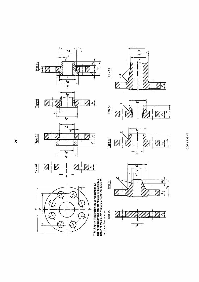
www.bzfxw.com26
CO
PY
RIG
HT
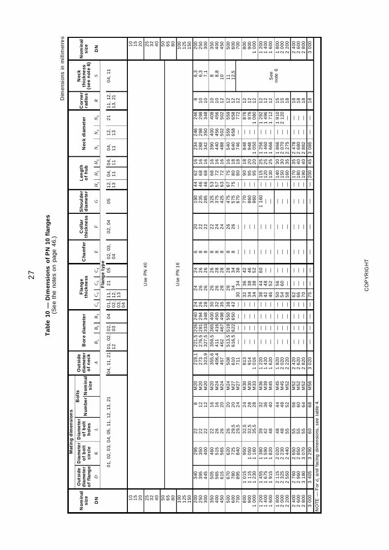
www.bzfxw.com27
Tab
le10
—D
imen
sio
ns
of
PN
10fl
ang
es(S
ee
the
note
so
npa
ge4
6.)
Dim
ensi
ons
inm
illim
etre
s
Mat
ing
dim
ensi
on
s
No
min
als
ize
Ou
tsid
ed
iam
ete
ro
ffl
an
ge
Dia
me
ter
of
bo
ltc
ircl
e
Dia
me
ter
of
bo
lth
ole
s
Bo
lts
Ou
tsid
ed
iam
ete
ro
fn
eck
Bo
red
iam
ete
rF
lan
ge
thic
kn
ess
Ch
am
fer
Co
lla
rth
ick
ne
ssS
ho
uld
er
dia
me
ter
Len
gth
of
hu
bN
eck
dia
met
erC
orn
er
rad
ius
Nec
kth
ick
ne
ss(s
ee
no
te6)
No
min
als
ize
Nu
mb
er
No
min
als
ize
DN
DK
LA
B1
B2
B3
C1
C2
C3
C4
EF
GH
1H
2H
3N
1N
2N
3R
SD
NF
lan
ge
typ
e0
1,02
,03,
04,
05,
11,
12,
13,
210
4,11
,21
01,
02,
12
02,
03
04
01,
02,
03,
04
11,
12, 13
21
05
02,
03,
04
02,
040
51
2,1
30
4,1
10
4,1
10
4,1
11
2,1
32
11
1,12
,1
3,21
04,
11
10
15
20
Use
PN
40
10
15
20
25
32
40
25
32
40
50
65
80
Use
PN
16
50
65
80
100
125
150
100
125
150
200
250
300
340
395
445
295
350
400
22
22
22
8 12
12
M20
M20
M20
219
,12
733
23,9
221
,52
76,5
327
,5
226
281
333
240
294
348
24
26
28
24
26
26
24
26
26
6 8 8
20
22
22
190
235
285
44
46
46
62
68
68
16
16
16
234
288
342
246
298
350
246
298
348
81
01
0
6,3
6,3
7,1
200
250
300
350
400
450
505
565
615
460
515
565
22
26
26
16
16
20
M20
M24
M24
355
,64
06,4
457
359
,54
114
62
365
416
467
400
450
498
30
32
35
26
26
28
26
28
28
8 8 8
22
24
24
325
375
425
53
57
63
68
72
72
16
16
16
390
440
488
400
456
502
408
456
502
10
10
12
8 8,8
10
350
400
450
500
600
700
670
780
895
620
725
840
26
29,
52
9,5
20
20
24
M24
M27
M27
508
610
711
513
,56
16,5
—
519
622 —
550
650 —
38
42 —
30
28
34 3
4
28
34
38
8 8 —
26
26 —
475
575
670
67
75 —
75
80
80
16
18
18
540
640
746
559
658 —
559
658
772
12
12
12
11
12,
55
006
007
008
009
001
000
10
151
115
12
30
950
10
501
160
32,
53
2,5
35,
5
24
28
28
M30
M30
M33
813
914
10
16
— — —
— — —
— — —
— — —
32
34
34
36
38
38
42
46
52
— — —
— — —
770
860
960
— — —
90
95
95
18
20
20
848
948
10
50
— — —
876
976
10
80
12
12
12
800
900
10
001
200
14
001
600
14
551
675
19
15
13
801
590
18
20
39
42
48
32
36
40
M36
M39
M45
12
201
420
16
20
— — —
— — —
— — —
— — —
38
42
46
44
48
52
60 — —
— — —
— — —
11
60— —
— — —
115
120
130
25
25
25
12
561
460
16
66
— — —
12
921
496
17
12
12
12
12
See
not
e6
12
001
400
16
00
18
002
000
22
00
21
152
325
25
50
20
202
230
24
40
48
48
55
44
48
52
M45
M45
M52
18
202
020
22
20
— — —
— — —
— — —
— — —
50
54
58
56
60 —
— — —
— — —
— — —
— — —
— — —
140
150
160
30
30
35
18
662
070
22
75
— — —
19
102
120
—
15
15
18
18
002
000
22
002
400
26
002
800
27
602
960
31
80
26
502
850
30
70
55
55
55
56
60
64
M52
M52
M52
24
202
620
28
20
— — —
— — —
— — —
— — —
62
66
70
— — —
— — —
— — —
— — —
— — —
— — —
170
180
190
35
40
40
24
782
680
28
82
— — —
— — —
18
18
18
24
002
600
28
003
000
34
053
290
60
68
M56
30
20—
——
—7
5—
——
——
—2
004
53
085
——
18
30
00
NO
TE
—F
ord 1
and
faci
ngdi
men
sion
s,se
eta
ble
4.
CO
PY
RIG
HT
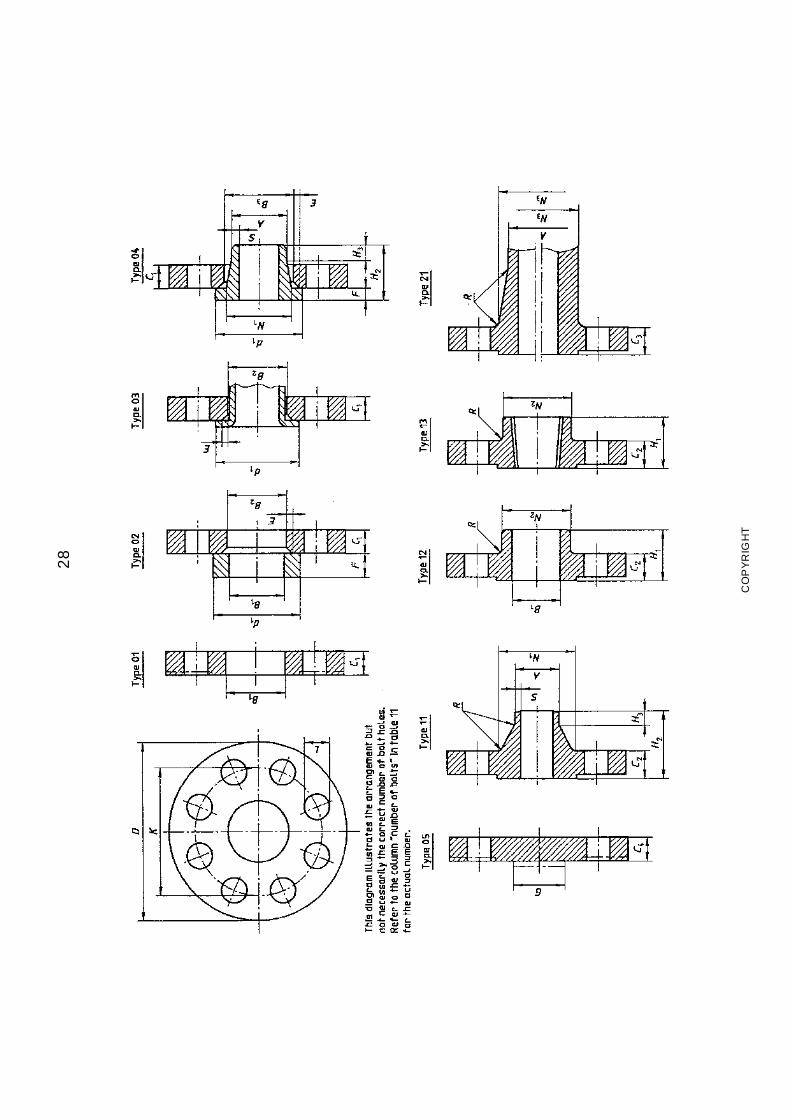
www.bzfxw.com28
CO
PY
RIG
HT
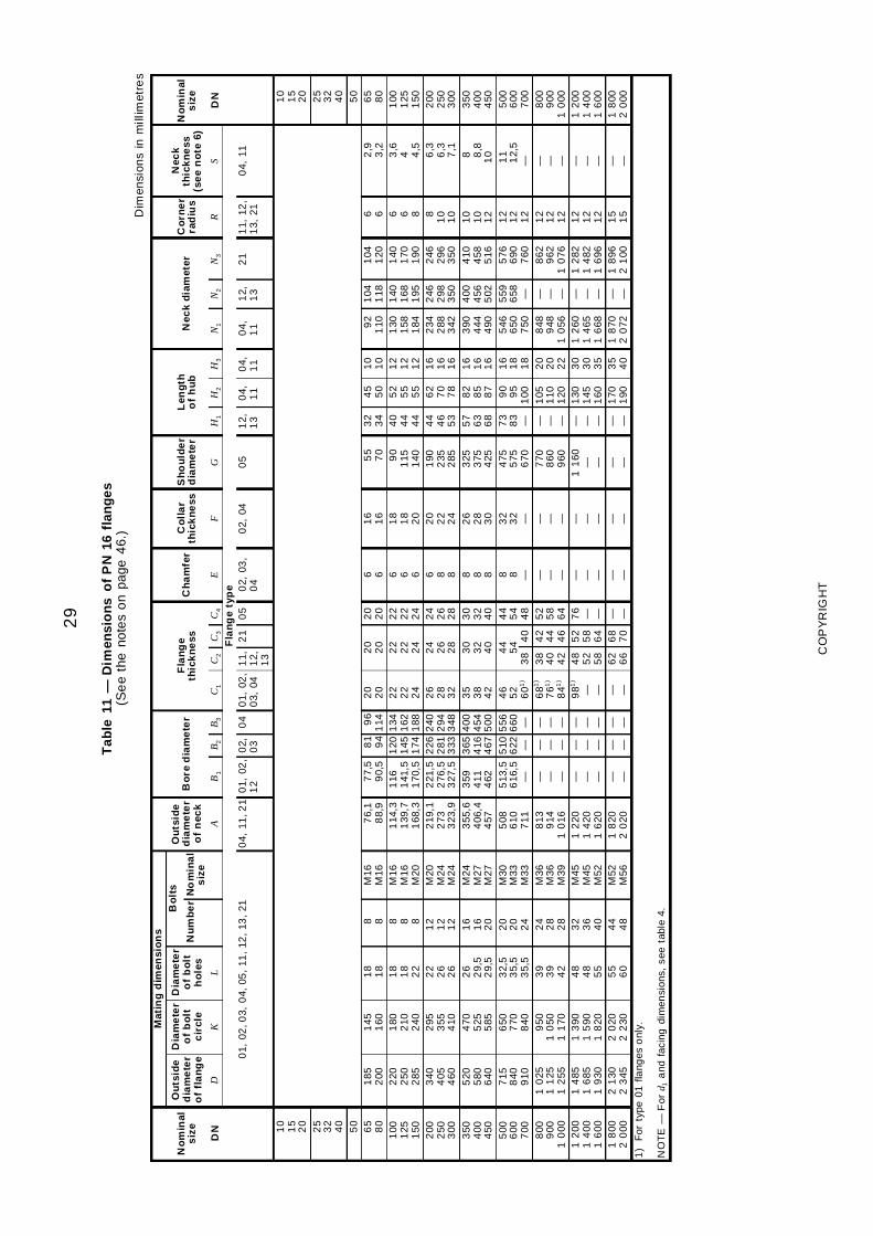
www.bzfxw.com29
Tab
le11
—D
imen
sio
ns
of
PN
16fl
ang
es(S
ee
the
note
so
npa
ge4
6.)
Dim
ensi
ons
inm
illim
etre
s
Mat
ing
dim
ensi
on
s
No
min
als
ize
Ou
tsid
ed
iam
ete
ro
ffl
an
ge
Dia
me
ter
of
bo
ltc
ircl
e
Dia
me
ter
of
bo
lth
ole
s
Bo
lts
Ou
tsid
ed
iam
ete
ro
fn
eck
Bo
red
iam
ete
rF
lan
ge
thic
kn
ess
Ch
am
fer
Co
lla
rth
ick
ne
ssS
ho
uld
er
dia
me
ter
Len
gth
of
hu
bN
eck
dia
met
erC
orn
er
rad
ius
Nec
kth
ick
ne
ss(s
ee
no
te6)
No
min
als
ize
Nu
mb
er
No
min
al
siz
eD
ND
KL
AB
1B
2B
3C
1C
2C
3C
4E
FG
H1
H2
H3
N1
N2
N3
RS
DN
Fla
ng
ety
pe
01,
02,0
3,0
4,05
,11
,12
,13
,21
04,
11,2
10
1,02
,1
20
2,0
30
40
1,02
,0
3,04
11,
12,
13
21
05
02,
03,
04
02,
040
51
2,1
30
4, 11
04,
11
04,
11
12,
13
21
11,
12,
13,
210
4,11
10
15
20
10
15
20
25
32
40
25
32
40
50
50
65
80
185
200
145
160
18
18
8 8M
16M
167
6,1
88,
97
7,5
90,
58
19
49
61
142
02
02
02
02
02
06 6
16
16
55
70
32
34
45
50
10
10
92
110
104
118
104
120
6 62
,93
,26
58
01
001
251
50
220
250
285
180
210
240
18
18
22
8 8 8
M16
M16
M20
114
,31
39,7
168
,3
116
141
,51
70,5
120
145
174
134
162
188
22
22
24
22
22
24
22
22
24
6 6 6
18
18
20
90
115
140
40
44
44
52
55
55
12
12
12
130
158
184
140
168
195
140
170
190
6 6 8
3,6
4 4,5
100
125
150
200
250
300
340
405
460
295
355
410
22
26
26
12
12
12
M20
M24
M24
219
,12
733
23,9
221
,52
76,5
327
,5
226
281
333
240
294
348
26
28
32
24
26
28
24
26
28
6 8 8
20
22
24
190
235
285
44
46
53
62
70
78
16
16
16
234
288
342
246
298
350
246
296
350
81
01
0
6,3
6,3
7,1
200
250
300
350
400
450
520
580
640
470
525
585
26
29,
52
9,5
16
16
20
M24
M27
M27
355
,64
06,4
457
359
411
462
365
416
467
400
454
500
35
38
42
30
32
40
30
32
40
8 8 8
26
28
30
325
375
425
57
63
68
82
85
87
16
16
16
390
444
490
400
456
502
410
458
516
10
10
12
8 8,8
10
350
400
450
500
600
700
715
840
910
650
770
840
32,
53
5,5
35,
5
20
20
24
M30
M33
M33
508
610
711
513
,56
16,5
—
510
622 —
556
660 —
46
52
601
)3
844
54 4
0
44
54
48
8 8 —
32
32 —
475
575
670
73
83 —
90
95
100
16
18
18
546
650
750
559
658 —
576
690
760
12
12
12
11
12,
5—
500
600
700
800
900
10
00
10
251
125
12
55
950
10
501
170
39
39
42
24
28
28
M36
M36
M39
813
914
10
16
— — —
— — —
— — —
681
)
761
)
841
)
38
40
42
42
44
46
52
58
64
— — —
— — —
770
860
960
— — —
105
110
120
20
20
22
848
948
10
56
— — —
862
962
10
76
12
12
12
— — —
800
900
10
001
200
14
001
600
14
851
685
19
30
13
901
590
18
20
48
48
55
32
36
40
M45
M45
M52
12
201
420
16
20
— — —
— — —
— — —
981
)
— —
48
52
58
52
58
64
76 — —
— — —
— — —
11
60— —
— — —
130
145
160
30
30
35
12
601
465
16
68
— — —
12
821
482
16
96
12
12
12
— — —
12
001
400
16
001
800
20
002
130
23
452
020
22
305
56
04
44
8M
52M
561
820
20
20— —
— —— —
— —6
26
66
87
0— —
— —— —
— —— —
170
190
35
40
18
702
072
— —1
896
21
001
51
5— —
18
002
000
1)
For
type
01fla
nges
onl
y.
NO
TE
—F
ord 1
and
faci
ngdi
men
sion
s,se
eta
ble
4.
CO
PY
RIG
HT
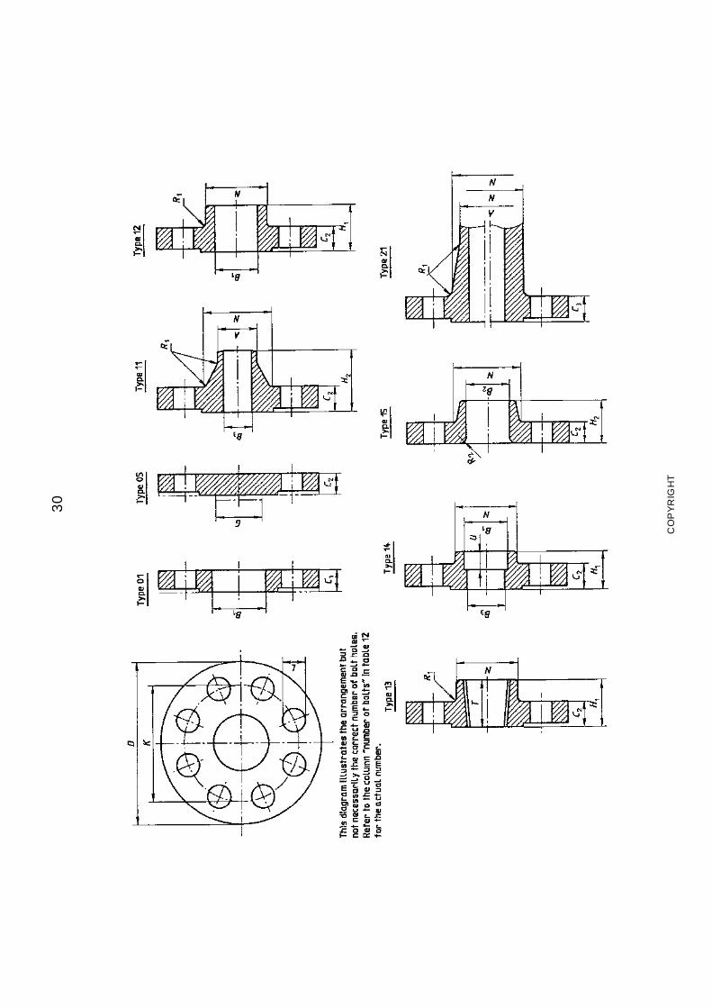
www.bzfxw.com30
CO
PY
RIG
HT
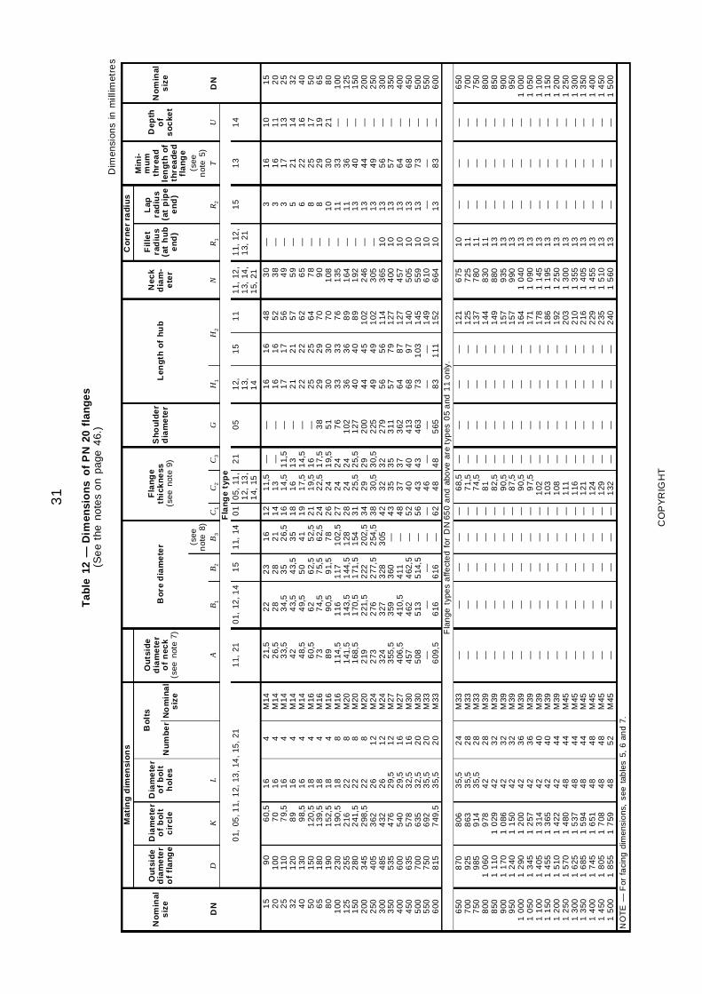
www.bzfxw.com31
Tab
le12
—D
imen
sio
ns
of
PN
20fl
ang
es(S
ee
the
note
so
npa
ge4
6.)
Dim
ensi
ons
inm
illim
etre
s
Mat
ing
dim
ensi
on
sC
orn
er
rad
ius
No
min
als
ize
Ou
tsid
ed
iam
ete
ro
ffl
an
ge
Dia
me
ter
of
bo
ltc
ircl
e
Dia
me
ter
of
bo
lth
ole
s
Bo
lts
Ou
tsid
ed
iam
ete
ro
fn
eck
(see
note
7)
Bo
red
iam
ete
rF
lan
ge
thic
kn
ess
(see
note
9)
Sh
ou
lde
rd
iam
ete
rL
eng
tho
fh
ub
Nec
kd
iam
-e
ter
Fil
let
rad
ius
(at
hu
be
nd
)
Lap
rad
ius
(at
pip
ee
nd
)
Min
i-m
um
thre
ad
len
gth
of
thre
ad
ed
fla
ng
e
Dep
tho
fs
oc
ket
No
min
als
ize
Nu
mb
er
No
min
al
siz
e
(see
not
e8)
(see
not
e5)
DN
DK
LA
B1
B2
B3
C1
C2
C3
GH
1H
2N
R1
R2
TU
DN
Fla
ng
ety
pe
01,
05,1
1,1
2,13
,14
,15
,21
11,
210
1,12
,14
15
11,
140
10
5,11
,1
2,13
,1
4,15
21
05
12,
13,
14
15
11
11,
12,
13,
14,
15,
21
11,
12,
13,
211
51
31
4
15
20
25
32
40
50
65
80
100
125
150
200
250
300
350
400
450
500
550
600
90
100
110
120
130
150
180
190
230
255
280
345
405
485
535
600
635
700
750
815
60,
57
07
9,5
89
98,
51
20,5
139
,51
52,5
190
,52
162
41,5
298
,53
624
324
765
405
786
356
927
49,5
16
16
16
16
16
18
18
18
18
22
22
22
26
26
29,
52
9,5
32,
53
2,5
35,
53
5,5
4 4 4 4 4 4 4 4 8 8 8 8 12
12
12
16
16
20
20
20
M14
M14
M14
M14
M14
M16
M16
M16
M16
M20
M20
M20
M24
M24
M27
M27
M30
M30
M33
M33
21,
52
6,5
33,
54
24
8,5
60,
57
38
91
14,5
141
,51
68,5
219
273
324
355
,54
06,5
457
508 — 609
,5
22
28
34,
54
3,5
49,
56
27
4,5
90,
51
161
43,5
170
,52
21,5
276
327
359
410
,54
625
13 —6
16
23
28
35
43,
55
06
2,5
75,
59
1,5
117
144
,51
71,5
222
277
,53
283
604
114
62,5
514
,5—
616
16
21
26,
53
54
15
2,5
62,
57
81
02,5
128
154
202
,52
54,5
305 — — — — — —
12
14
16
18
19
21
24
26
27
28
31
34
38
42
43
48
52
56 — 62
11,
51
31
4,5
16
17,
51
9,5
22,
52
42
42
42
5,5
29
30,
53
23
53
74
04
34
64
8
— — 11,
51
31
4,5
16
17,
51
9,5
24
24
25,
52
93
0,5
32
35
37
40
43 — 48
— — — — — — 38
51
76
102
127
200
225
279
311
362
413
463 — 565
16
16
17
21
22
25
29
30
33
36
40
44
49
56
57
64
68
73 — 83
16
16
17
21
22
25
29
30
33
36
40
45
49
56
79
87
97
103 — 111
48
52
56
57
62
64
70
70
76
89
89
102
102
114
127
127
140
145
149
152
30
38
49
59
65
78
90
108
135
164
192
246
305
365
400
457
505
559
610
664
— — — — — — — — — — — — — 10
10
10
10
10
10
10
3 3 3 5 6 8 8 10
11
11
13
13
13
13
13
13
13
13 — 13
16
16
17
21
22
25
29
30
33
36
40
44
49
56
57
64
68
73 — 83
10
11
13
14
16
17
19
21 — — — — — — — — — — — —
15
20
25
32
40
50
65
80
100
125
150
200
250
300
350
400
450
500
550
600
Fla
nge
type
sa
ffect
ed
for
DN
650
and
abo
vear
ety
pes
05
and
11
onl
y.6
507
007
508
008
509
009
501
000
10
501
100
11
501
200
12
501
300
13
501
400
14
501
500
870
925
985
10
601
110
11
701
240
12
901
345
14
051
455
15
101
570
16
251
685
17
451
805
18
55
806
863
914
978
10
291
086
11
501
200
12
571
314
13
651
422
14
801
537
15
941
651
17
081
759
35,
53
5,5
35,
54
24
24
24
24
24
24
24
24
24
84
84
84
84
84
8
24
28
28
28
32
32
32
36
36
40
40
44
44
44
44
48
48
52
M33
M33
M33
M39
M39
M39
M39
M39
M39
M39
M39
M39
M45
M45
M45
M45
M45
M45
— — — — — — — — — — — — — — — — — —
— — — — — — — — — — — — — — — — — —
— — — — — — — — — — — — — — — — — —
— — — — — — — — — — — — — — — — — —
— — — — — — — — — — — — — — — — — —
68,
57
1,5
74,
58
18
2,5
90,
58
7,5
90,
59
7,5
102
103
108
111
116
121
124
129
132
— — — — — — — — — — — — — — — — — —
— — — — — — — — — — — — — — — — — —
— — — — — — — — — — — — — — — — — —
— — — — — — — — — — — — — — — — — —
121
125
137
144
149
157
157
164
171
178
186
192
203
210
216
229
235
240
675
725
780
830
880
935
990
10
401
090
11
451
195
12
501
300
13
551
405
14
551
510
15
60
10
11
11
11
13
13
13
13
13
13
13
13
13
13
13
13
13
13
— — — — — — — — — — — — — — — — — —
— — — — — — — — — — — — — — — — — —
— — — — — — — — — — — — — — — — — —
650
700
750
800
850
900
950
10
001
050
11
001
150
12
001
250
13
001
350
14
001
450
15
00
NO
TE
—F
orfa
cin
gdi
men
sio
ns,
see
tab
les
5,6
and
7.
CO
PY
RIG
HT
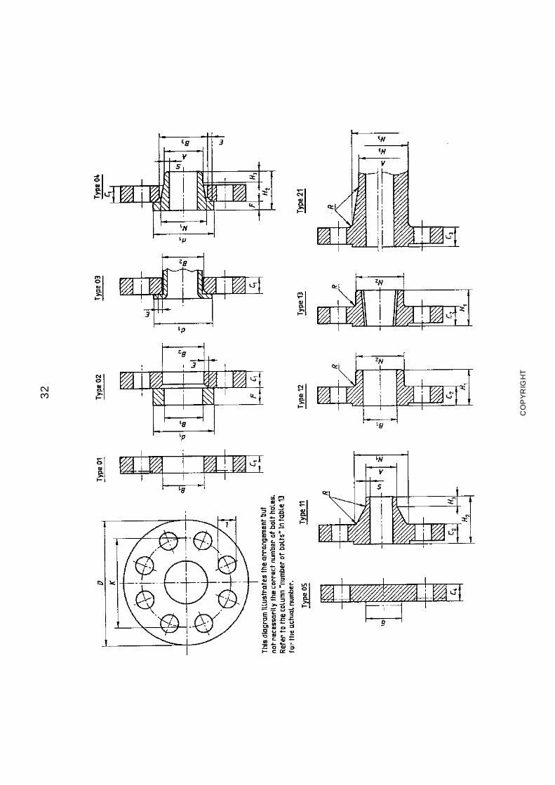
32
CO
PY
RIG
HT
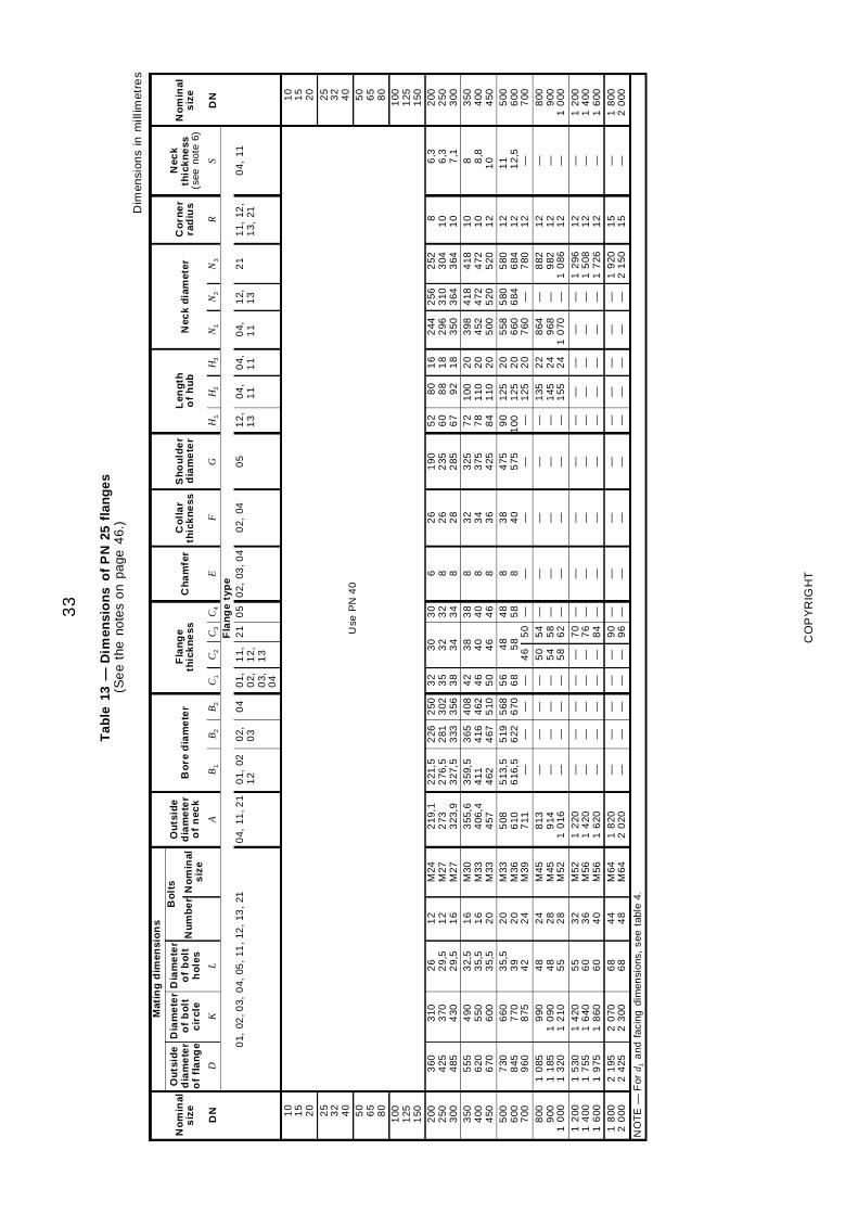
33
Tab
le13
—D
imen
sio
ns
of
PN
25fl
ang
es(S
ee
the
note
so
npa
ge4
6.)
Dim
ensi
ons
inm
illim
etre
s
Mat
ing
dim
ensi
on
s
No
min
als
ize
Ou
tsid
ed
iam
ete
ro
ffl
an
ge
Dia
me
ter
of
bo
ltc
ircl
e
Dia
me
ter
of
bo
lth
ole
s
Bo
lts
Ou
tsid
ed
iam
ete
ro
fn
eck
Bo
red
iam
ete
rF
lan
ge
thic
kn
ess
Ch
am
fer
Co
lla
rth
ick
ne
ssS
ho
uld
er
dia
me
ter
Len
gth
of
hu
bN
eck
dia
met
erC
orn
er
rad
ius
Nec
kth
ick
ne
ss(s
eeno
te6)
No
min
als
ize
Nu
mb
er
No
min
als
ize
DN
DK
LA
B1
B2
B2
C1
C2
C3
C4
EF
GH
1H
2H
3N
1N
2N
3R
SD
NF
lan
ge
typ
e0
1,02
,03,
04,
05,
11,
12,
13,
210
4,11
,21
01,
021
20
2,0
30
40
1,0
2,0
3,0
4
11,
12,
13
21
05
02,
03,0
40
2,04
05
12,
13
04,
11
04,
11
04,
11
12,
13
21
11,
12,
13,
210
4,11
10
15
20
Use
PN
40
10
15
20
25
32
40
25
32
40
50
65
80
50
65
80
100
125
150
100
125
150
200
250
300
360
425
485
310
370
430
26
29,
52
9,5
12
12
16
M24
M27
M27
219
,12
733
23,9
221
,52
76,5
327
,5
226
281
333
250
302
356
32
35
38
30
32
34
30
32
34
6 8 8
26
26
28
190
235
285
52
60
67
80
88
92
16
18
18
244
296
350
256
310
364
252
304
364
81
01
0
6,3
6,3
7,1
200
250
300
350
400
450
555
620
670
490
550
600
32,
53
5,5
35,
5
16
16
20
M30
M33
M33
355
,64
06,4
457
359
,54
114
62
365
416
467
408
462
510
42
46
50
38
40
46
38
40
46
8 8 8
32
34
36
325
375
425
72
78
84
100
110
110
20
20
20
398
452
500
418
472
520
418
472
520
10
10
12
8 8,8
10
350
400
450
500
600
700
730
845
960
660
770
875
35,
53
94
2
20
20
24
M33
M36
M39
508
610
711
513
,56
16,5
—
519
622 —
568
670 —
56
68 —
464
85
85
0
48
58 —
8 8 —
38
40 —
475
575 —
90
100 —
125
125
125
20
20
20
558
660
760
580
684 —
580
684
780
12
12
12
11
12,
5—
500
600
700
800
900
10
00
10
851
185
13
20
990
10
901
210
48
48
55
24
28
28
M45
M45
M52
813
914
10
16
— — —
— — —
— — —
— — —
50
54
58
54
58
62
— — —
— — —
— — —
— — —
— — —
135
145
155
22
24
24
864
968
10
70
— — —
882
982
10
86
12
12
12
— — —
800
900
10
001
200
14
001
600
15
301
755
19
75
14
201
640
18
60
55
60
60
32
36
40
M52
M56
M56
12
201
420
16
20
— — —
— — —
— — —
— — —
— — —
70
76
84
— — —
— — —
— — —
— — —
— — —
— — —
— — —
— — —
— — —
12
961
508
17
26
12
12
12
— — —
12
001
400
16
001
800
20
002
195
24
252
070
23
006
86
84
44
8M
64M
641
820
20
20— —
— —— —
— —— —
90
96
— —— —
— —— —
— —— —
— —— —
— —1
920
21
501
51
5— —
18
002
000
NO
TE
—F
ord 1
and
faci
ngdi
men
sion
s,se
eta
ble
4.
CO
PY
RIG
HT
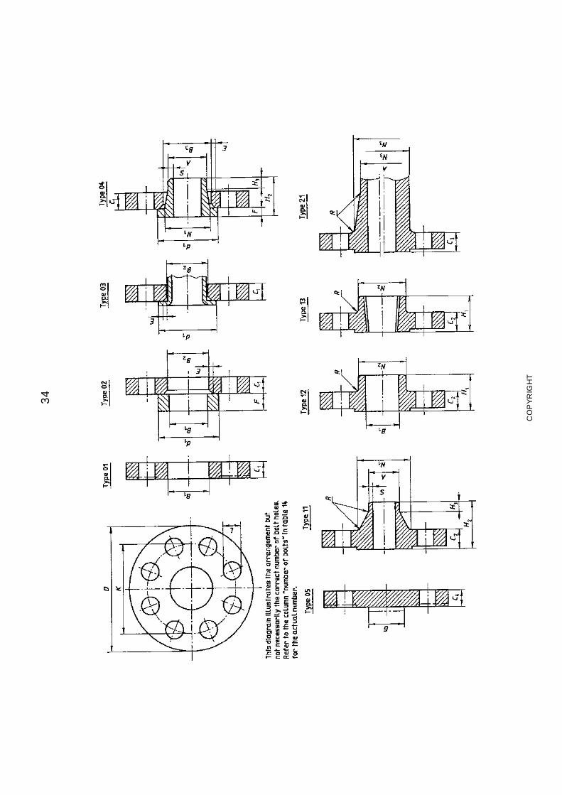
34
CO
PY
RIG
HT
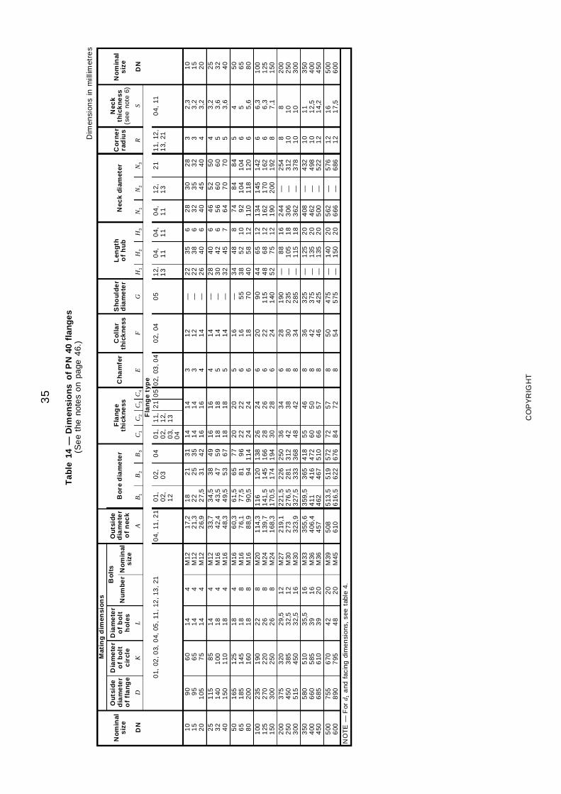
35
Tab
le14
—D
imen
sio
ns
of
PN
40fl
ang
es(S
ee
the
note
so
npa
ge4
6.)
Dim
ensi
ons
inm
illim
etre
s
Mat
ing
dim
ensi
on
s
No
min
als
ize
Ou
tsid
ed
iam
ete
ro
ffl
an
ge
Dia
me
ter
of
bo
ltc
ircl
e
Dia
me
ter
of
bo
lth
ole
s
Bo
lts
Ou
tsid
ed
iam
ete
ro
fn
eck
Bo
red
iam
ete
rF
lan
ge
thic
kn
ess
Ch
am
fer
Co
lla
rth
ick
ne
ssS
ho
uld
er
dia
me
ter
Len
gth
of
hu
bN
eck
dia
met
erC
orn
er
rad
ius
Nec
kth
ick
ne
ss(s
eeno
te6)
No
min
als
ize
Nu
mb
er
No
min
als
ize
DN
DK
LA
B1
B2
B3
C1
C2
C3
C4
EF
GH
1H
2H
3N
1N
2N
3R
SD
NF
lan
ge
typ
e0
1,02
,03,
04,
05,
11,
12,
13,
210
4,11
,21
01,
02,
12
02,
03
04
01,
02,
03,
04
11,
12,
13
21
05
02,
03,0
40
2,04
05
12,
13
04,
11
04,
11
04,
11
12,
13
21
11,
12,
13,
210
4,11
10
15
20
90
95
105
60
65
75
14
14
14
4 4 4
M12
M12
M12
17,
22
1,3
26,
9
18
22
27,
5
21
25
31
31
35
42
14
14
16
14
14
16
3 3 4
12
12
14
— — —
22
22
26
35
38
40
6 6 6
28
32
40
30
35
45
28
32
40
3 3 4
2,3
3,2
3,2
10
15
20
25
32
40
115
140
150
85
100
110
14
18
18
4 4 4
M12
M16
M16
33,
74
2,4
48,
3
34,
54
3,5
49,
5
38
47
53
49
59
67
16
18
18
16
18
18
4 5 5
14
14
14
— — —
28
30
32
40
42
45
6 6 7
46
56
64
52
60
70
50
60
70
4 5 5
3,2
3,6
3,6
25
32
40
50
65
80
165
185
200
125
145
160
18
18
18
4 8 8
M16
M16
M16
60,
37
6,1
88,
9
61,
57
7,5
90,
5
65
81
94
77
96
114
20
22
24
20
22
24
5 6 6
16
16
18
— 55
70
34
38
40
48
52
58
8 10
12
74
92
110
84
104
118
84
104
120
5 6 6
4 5 5,6
50
65
80
100
125
150
235
270
300
190
220
250
22
26
26
8 8 8
M20
M24
M24
114
,31
39,7
168
,3
116
141
,51
70,5
120
145
174
138
166
194
26
28
30
24
26
28
6 6 6
20
22
24
90
115
140
44
48
52
65
68
75
12
12
12
134
162
190
145
170
200
142
162
192
6 6 8
6,3
6,3
7,1
100
125
150
200
250
300
375
450
515
320
385
450
29,
53
2,5
32,
5
12
12
16
M27
M30
M30
219
,12
733
23,9
221
,52
76,5
327
,5
226
281
333
250
312
368
36
42
48
34
38
42
6 8 8
28
30
34
190
235
285
— — —
88
105
115
16
18
18
244
306
362
— — —
254
312
378
8 10
10
81
01
0
200
250
300
350
400
450
580
660
685
510
585
610
35,
53
93
9
16
16
20
M33
M36
M36
355
,64
06,4
457
359
,54
114
62
365
416
467
418
472
510
55
60
66
46
50
57
8 8 8
36
42
46
325
375
425
— — —
125
135
135
20
20
20
408
462
500
— — —
432
498
522
10
10
12
11
12,
51
4,2
350
400
450
500
600
755
890
670
795
42
48
20
20
M39
M45
508
610
513
,56
16,5
519
622
572
676
72
84
57
72
8 85
05
44
755
75— —
140
150
20
20
562
666
— —5
766
861
21
21
61
7,5
500
600
NO
TE
—F
ord 1
and
faci
ngdi
men
sion
s,se
eta
ble
4.
CO
PY
RIG
HT
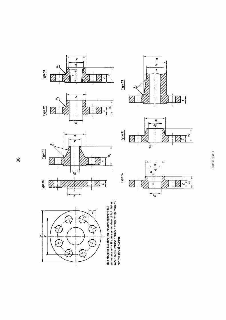
36
CO
PY
RIG
HT
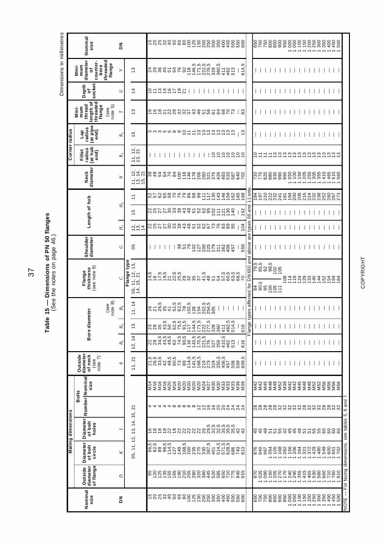
37
Tab
le15
—D
imen
sio
ns
of
PN
50fl
ang
es(S
ee
the
note
so
npa
ge4
6.)
Dim
ensi
ons
inm
illim
etre
s
Mat
ing
dim
ensi
on
sC
orn
er
rad
ius
No
min
als
ize
Ou
tsid
ed
iam
ete
ro
ffl
an
ge
Dia
me
ter
of
bo
ltc
ircl
e
Dia
me
ter
of
bo
lth
ole
s
Bo
lts
Ou
tsid
ed
iam
ete
ro
fn
eck
(see
not
e7)
Bo
red
iam
ete
rF
lan
ge
thic
kn
ess
(see
note
9)
Sh
ou
lde
rd
iam
ete
rL
eng
tho
fh
ub
Nec
kd
iam
ete
r
Fil
let
rad
ius
(at
hu
be
nd
)
Lap
rad
ius
(at
pip
ee
nd
)
Min
i-m
um
thre
ad
len
gth
of
thre
ad
ed
fla
ng
e
Dep
tho
fs
oc
ket
Min
i-m
um
dia
me
ter
of
co
un
ter-
bo
reth
rea
de
dfl
an
ge
No
min
als
ize
Nu
mb
er
No
min
als
ize
(see
not
e8)
(see
not
e5)
DN
DK
LA
B1
B2
B3
CG
H1
H2
NR
1R
2T
UV
DN
Fla
ng
ety
pe
05,
11,1
2,1
3,14
,15
,21
11,
211
2,14
15
11,
140
5,11
,12,
13,
14,
15,2
10
51
2,1
3, 14
15
11
11,
12,
13,
14,
15,
21
11,
12,
13,
211
51
31
41
3
15
20
25
32
40
50
65
80
100
125
150
200
250
300
350
400
450
500
550
600
95
120
125
135
155
165
190
210
255
280
320
380
445
520
585
650
710
775
840
915
66,
58
2,5
89
98,
51
14,5
127
149
168
,52
002
352
703
303
87,5
451
514
,55
71,5
628
,56
867
438
13
16
18
18
18
22
18
22
22
22
22
22
26
29,
53
2,5
32,
53
5,5
35,
53
5,5
42
42
4 4 4 4 4 8 8 8 8 81
21
21
61
62
02
02
42
42
42
4
M14
M16
M16
M16
M20
M16
M20
M20
M20
M20
M20
M24
M27
M30
M30
M33
M33
M33
M39
M39
21,
52
6,5
33,
54
24
8,5
60,
57
38
91
14,5
141
,51
68,5
219
273
324
355
,54
06,5
457
508
559
609
,5
22
28
34,
54
3,5
49,
56
27
4,5
90,
51
161
43,5
170
,52
21,5
276
327
359
410
,54
625
13 —6
16
23
28
35
43,
55
06
2,5
75,
59
1,5
117
144
,51
71,5
222
277
,53
283
604
114
62,5
514
,5—
616
16
21
26,
53
54
15
2,5
62,
57
81
02,5
128
154
202
,52
54,5
305 — — — — — —
14,
51
61
7,5
19,
52
12
2,5
25,
52
93
23
53
74
1,5
48
51
54
57,
56
0,5
63,
56
6,5
70
— — — — — — 38
51
76
102
127
200
225
279
311
362
406
457 —
559
22
25
27
27
30
33
38
43
48
51
52
62
67
73
76
83
89
95
— 104
22
25
27
27
30
33
38
43
48
51
52
62
95
102
111
121
130
140 — 152
52
57
62
65
68
70
76
79
86
98
98
111
117
130
143
146
159
162
165
168
38
48
54
64
70
84
100
118
146
178
206
260
321
375
426
483
533
587
640
702
— — — — — — — — — — — — — 10
10
10
10
10
10
10
3 3 3 5 6 8 8 10
11
11
13
13
13
13
13
13
13
13
— 13
16
16
18
21
22
29
32
32
37
43
46
51
56
61
64
68
70
73 — 83
10
11
13
14
16
17
19
21 — — — — — — — — — — — —
24
29
36
45
51
64
76
92
118
146
,51
71,5
222
,52
76,5
329
360
,54
114
625
13 —6
14,5
15
20
25
32
40
50
65
80
100
125
150
200
250
300
350
400
450
500
550
600
Fla
nge
type
sa
ffect
ed
for
DN
650
and
abo
vear
ety
pes
05
and
11
onl
y.6
507
007
508
008
509
009
501
000
10
501
100
11
501
200
12
501
300
13
501
400
14
501
500
970
10
351
090
11
501
205
12
701
170
12
401
290
13
551
415
14
651
530
15
801
660
17
101
760
18
10
876
940
997
10
541
105
11
681
092
11
561
206
12
641
321
13
721
429
14
801
549
16
001
651
17
02
45
45
48
51
51
55
42
45
45
48
51
51
55
55
60
60
60
60
28
28
28
28
28
32
32
32
32
32
28
32
32
32
28
28
32
32
M42
M42
M45
M48
M48
M52
M39
M42
M42
M45
M48
M48
M52
M52
M56
M56
M56
M56
— — — — — — — — — — — — — — — — — —
— — — — — — — — — — — — — — — — — —
— — — — — — — — — — — — — — — — — —
— — — — — — — — — — — — — — — — — —
84
90,
59
51
001
051
11
79,
58
5,5
92
98,
51
021
051
081
141
191
241
291
331
401
441
521
541
591
64
— — — — — — — — — — — — — — — — — —
— — — — — — — — — — — — — — — — — —
— — — — — — — — — — — — — — — — — —
184
197
210
222
232
241
181
194
200
206
216
224
232
238
252
260
267
273
720
775
825
880
935
990
995
10
501
100
11
501
205
12
551
305
13
551
410
14
651
515
15
65
10
11
11
11
13
13
13
13
13
13
13
13
13
13
13
13
13
13
— — — — — — — — — — — — — — — — — —
— — — — — — — — — — — — — — — — — —
— — — — — — — — — — — — — — — — — —
— — — — — — — — — — — — — — — — — —
650
700
750
800
850
900
950
10
001
050
11
001
150
12
001
250
13
001
350
14
001
450
15
00
NO
TE
—F
orfa
cin
gdi
men
sio
ns,
see
tab
les
5,6
and
7.
CO
PY
RIG
HT
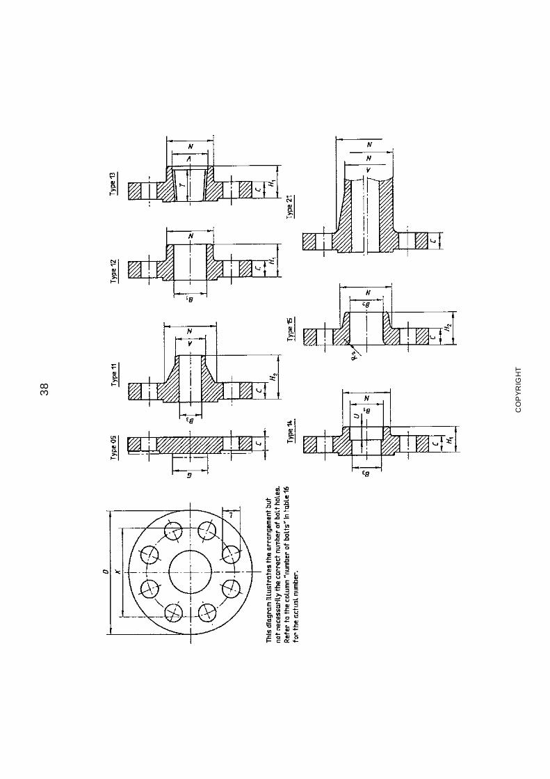
38
CO
PY
RIG
HT
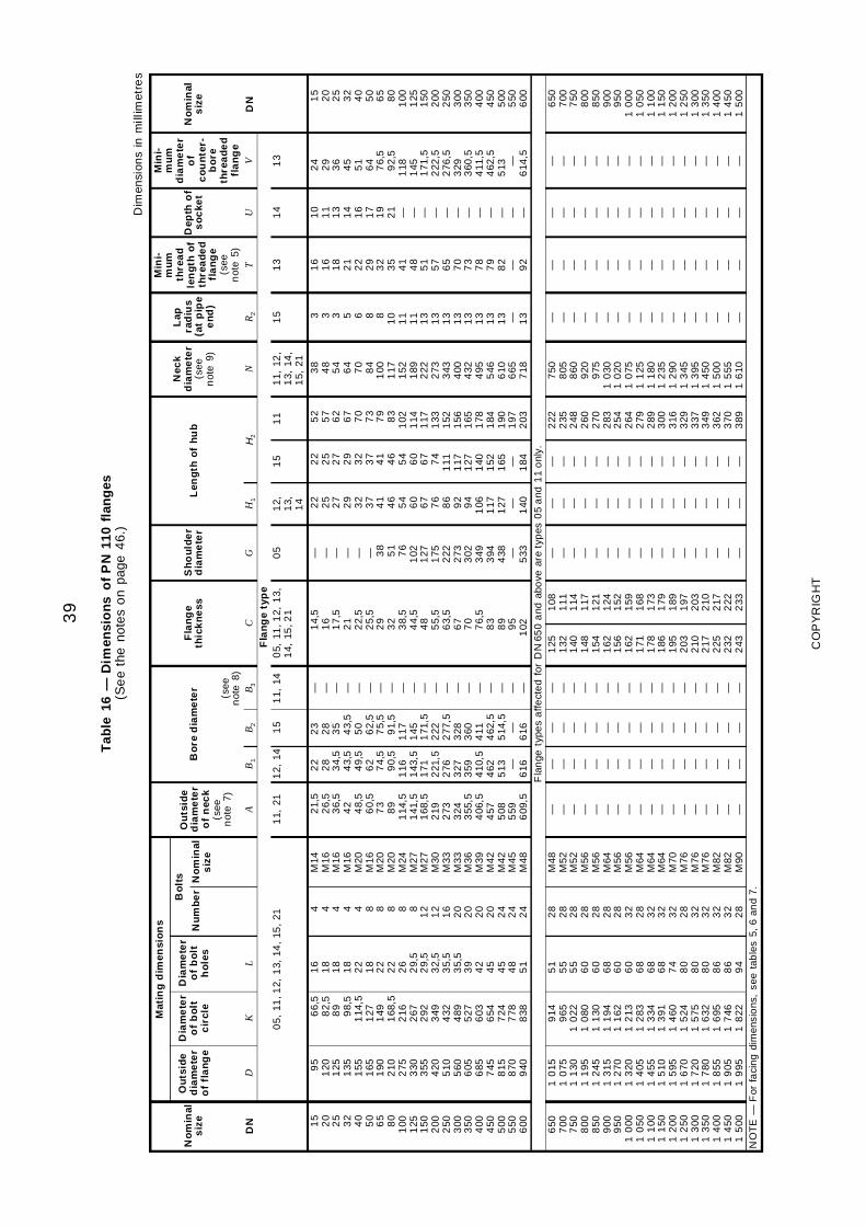
39
Tab
le16
—D
imen
sio
ns
of
PN
110
flan
ges
(Se
eth
eno
tes
on
page
46.
)D
imen
sion
sin
mill
imet
res
Mat
ing
dim
ensi
on
sM
ini-
mu
mth
rea
dle
ng
tho
fth
rea
de
dfl
an
ge
(see
not
e5)
Min
i-m
um
dia
me
ter
of
co
un
ter-
bo
reth
rea
de
dfl
an
ge
No
min
als
ize
Ou
tsid
ed
iam
ete
ro
ffl
an
ge
Dia
me
ter
of
bo
ltc
ircl
e
Dia
me
ter
of
bo
lth
ole
s
Bo
lts
Ou
tsid
ed
iam
ete
ro
fn
eck
(see
not
e7)
Bo
red
iam
ete
rF
lan
ge
thic
kn
ess
Sh
ou
lde
rd
iam
ete
rL
eng
tho
fh
ub
Nec
kd
iam
ete
r(s
een
ote
9)
Lap
rad
ius
(at
pip
ee
nd
)
Dep
tho
fs
oc
ket
No
min
als
ize
Nu
mb
er
No
min
als
ize
(see
not
e8)
DN
DK
LA
B1
B2
B3
CG
H1
H2
NR
2T
UV
DN
Fla
ng
ety
pe
05,
11,1
2,1
3,14
,15
,21
11,
211
2,14
15
11,
140
5,11
,12,
13,
14,
15,2
10
51
2,1
3, 14
15
11
11,
12,
13,
14,
15,
21
15
13
14
13
15
20
25
32
40
50
65
80
100
125
150
200
250
300
350
400
450
500
550
600
95
120
125
135
155
165
190
210
275
330
355
420
510
560
605
685
745
815
870
940
66,
58
2,5
89
98,
51
14,5
127
149
168
,52
162
672
923
494
324
895
276
036
547
247
788
38
16
18
18
18
22
18
22
22
26
29,
52
9,5
32,
53
5,5
35,
53
94
24
54
54
85
1
4 4 4 4 4 8 8 8 8 81
21
21
62
02
02
02
02
42
42
4
M14
M16
M16
M16
M20
M16
M20
M20
M24
M27
M27
M30
M33
M33
M36
M39
M42
M42
M45
M48
21,
52
6,5
36,
54
24
8,5
60,
57
38
91
14,5
141
,51
68,5
219
273
324
355
,54
06,5
457
508
559
609
,5
22
28
34,
54
3,5
49,
56
27
4,5
90,
51
161
43,5
171
221
,52
763
273
594
10,5
462
513 —
616
23
28
35
43,
55
06
2,5
75,
59
1,5
117
145
171
,52
222
77,5
328
360
411
462
,55
14,5
—6
16
— — — — — — — — — — — — — — — — — — — —
14,
51
61
7,5
21
22,
52
5,5
29
32
38,
54
4,5
48
55,
56
3,5
67
70
76,
58
38
99
51
02
— — — — — — 38
51
76
102
127
175
222
273
302
349
394
438 — 533
22
25
27
29
32
37
41
46
54
60
67
76
86
92
94
106
117
127 — 140
22
25
27
29
32
37
41
46
54
60
67
74
111
117
127
140
152
165 — 184
52
57
62
67
70
73
79
83
102
114
117
133
152
156
165
178
184
190
197
203
38
48
54
64
70
84
100
117
152
189
222
273
343
400
432
495
546
610
665
718
3 3 3 5 6 8 81
01
11
11
31
31
31
31
31
31
31
3 — 13
16
16
18
21
22
29
32
35
41
48
51
57
65
70
73
78
79
82 — 92
10
11
13
14
16
17
19
21 — — — — — — — — — — — —
24
29
36
45
51
64
76,
59
2,5
118
145
171
,52
22,5
276
,53
293
60,5
411
,54
62,5
513 —
614
,5
15
20
25
32
40
50
65
80
100
125
150
200
250
300
350
400
450
500
550
600
Fla
nge
type
sa
ffect
ed
for
DN
650
and
abo
vear
ety
pes
05
and
11
onl
y.6
507
007
508
008
509
009
501
000
10
501
100
11
501
200
12
501
300
13
501
400
14
501
500
10
151
075
11
301
195
12
451
315
12
701
320
14
051
455
15
101
595
16
701
720
17
801
855
19
051
995
914
965
10
221
080
11
301
194
11
621
213
12
831
334
13
911
460
15
241
575
16
321
695
17
461
822
51
55
55
60
60
68
60
60
68
68
68
74
80
80
80
86
86
94
28
28
28
28
28
28
28
32
28
32
32
32
28
32
32
32
32
28
M48
M52
M52
M56
M56
M64
M56
M56
M64
M64
M64
M70
M76
M76
M76
M82
M82
M90
— — — — — — — — — — — — — — — — — —
— — — — — — — — — — — — — — — — — —
— — — — — — — — — — — — — — — — — —
— — — — — — — — — — — — — — — — — —
125
132
140
148
154
162
156
162
171
178
186
195
203
210
217
225
232
243
108
111
114
117
121
124
152
159
168
173
179
189
197
203
210
217
222
233
— — — — — — — — — — — — — — — — — —
— — — — — — — — — — — — — — — — — —
— — — — — — — — — — — — — — — — — —
222
235
248
260
270
283
254
264
279
289
300
316
329
337
349
362
370
389
750
805
860
920
975
10
301
020
10
751
125
11
801
235
12
901
345
13
951
450
15
001
555
16
10
— — — — — — — — — — — — — — — — — —
— — — — — — — — — — — — — — — — — —
— — — — — — — — — — — — — — — — — —
— — — — — — — — — — — — — — — — — —
650
700
750
800
850
900
950
10
001
050
11
001
150
12
001
250
13
001
350
14
001
450
15
00N
OT
E—
For
faci
ng
dim
ensi
ons
,se
eta
ble
s5,
6an
d7.
CO
PY
RIG
HT
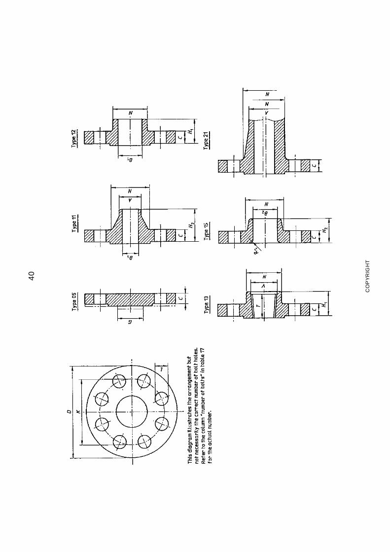
40
CO
PY
RIG
HT
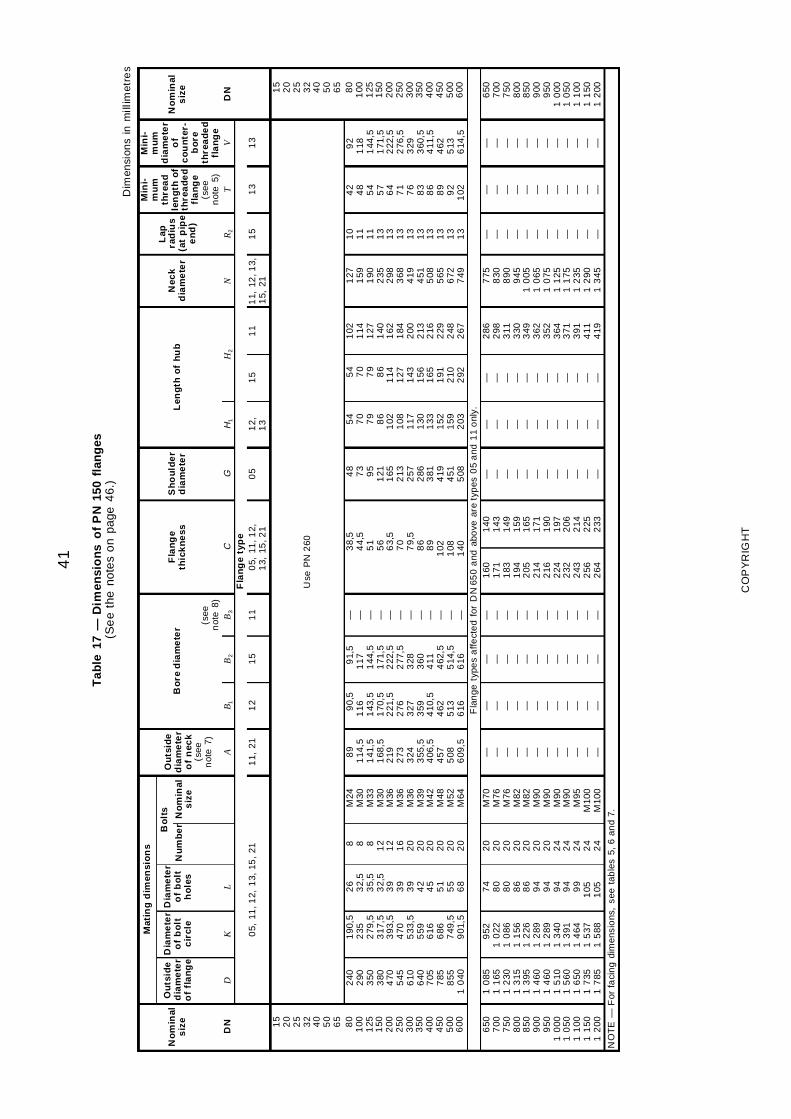
41
Tab
le17
—D
imen
sio
ns
of
PN
150
flan
ges
(Se
eth
eno
tes
on
page
46.
)D
imen
sion
sin
mill
imet
res
Mat
ing
dim
ensi
on
sM
ini-
mu
mth
rea
dle
ng
tho
fth
rea
de
dfl
an
ge
(see
not
e5)
Min
i-m
um
dia
me
ter
of
co
un
ter-
bo
reth
rea
de
dfl
an
ge
No
min
als
ize
Ou
tsid
ed
iam
ete
ro
ffl
an
ge
Dia
me
ter
of
bo
ltc
ircl
e
Dia
me
ter
of
bo
lth
ole
s
Bo
lts
Ou
tsid
ed
iam
ete
ro
fn
eck
(see
not
e7)
Bo
red
iam
ete
rF
lan
ge
thic
kn
ess
Sh
ou
lde
rd
iam
ete
rL
eng
tho
fh
ub
Nec
kd
iam
ete
r
Lap
rad
ius
(at
pip
ee
nd
)
No
min
als
ize
Nu
mb
er
No
min
als
ize
(see
not
e8)
DN
DK
LA
B1
B2
B3
CG
H1
H2
NR
2T
VD
NF
lan
ge
typ
e0
5,11
,12,
13,
15,
211
1,21
12
15
11
05,
11,1
2,1
3,15
,21
05
12,
13
15
11
11,
12,1
3,1
5,21
15
13
13
15
20
25
32
40
50
65
Use
PN
260
15
20
25
32
40
50
65
80
100
125
150
200
250
300
350
400
450
500
600
240
290
350
380
470
545
610
640
705
785
855
10
40
190
,52
352
79,5
317
,53
93,5
470
533
,55
596
166
867
49,5
901
,5
26
32,
53
5,5
32,
53
93
93
94
24
55
15
56
8
8 8 8 12
12
16
20
20
20
20
20
20
M24
M30
M33
M30
M36
M36
M36
M39
M42
M48
M52
M64
89
114
,51
41,5
168
,52
192
733
243
55,5
406
,54
575
086
09,5
90,
51
161
43,5
170
,52
21,5
276
327
359
410
,54
625
136
16
91,
51
171
44,5
171
,52
22,5
277
,53
283
604
114
62,5
514
,56
16
— — — — — — — — — — — —
38,
54
4,5
51
56
63,
57
07
9,5
86
89
102
108
140
48
73
95
121
165
213
257
286
381
419
451
508
54
70
79
86
102
108
117
130
133
152
159
203
54
70
79
86
114
127
143
156
165
191
210
292
102
114
127
140
162
184
200
213
216
229
248
267
127
159
190
235
298
368
419
451
508
565
672
749
10
11
11
13
13
13
13
13
13
13
13
13
42
48
54
57
64
71
76
83
86
89
92
102
92
118
144
,51
71,5
222
,52
76,5
329
360
,54
11,5
462
513
614
,5
80
100
125
150
200
250
300
350
400
450
500
600
Fla
nge
type
sa
ffect
ed
for
DN
650
and
abo
vear
ety
pes
05
and
11
onl
y.6
507
007
508
008
509
009
501
000
10
501
100
11
501
200
10
851
165
12
301
315
13
951
460
14
601
510
15
601
650
17
351
785
952
10
221
086
11
561
226
12
891
289
13
401
391
14
641
537
15
88
74
80
80
86
86
94
94
94
94
99
105
105
20
20
20
20
20
20
20
24
24
24
24
24
M70
M76
M76
M82
M82
M90
M90
M90
M90
M95
M10
0M
100
— — — — — — — — — — — —
— — — — — — — — — — — —
— — — — — — — — — — — —
— — — — — — — — — — — —
160
171
183
194
205
214
216
224
232
243
256
264
140
143
149
159
165
171
190
197
206
214
225
233
— — — — — — — — — — — —
— — — — — — — — — — — —
— — — — — — — — — — — —
286
298
311
330
349
362
352
364
371
391
411
419
775
830
890
945
10
051
065
10
751
125
11
751
235
12
901
345
— — — — — — — — — — — —
— — — — — — — — — — — —
— — — — — — — — — — — —
650
700
750
800
850
900
950
10
001
050
11
001
150
12
00
NO
TE
—F
orfa
cin
gdi
men
sio
ns,
see
tab
les
5,6
and
7.
CO
PY
RIG
HT
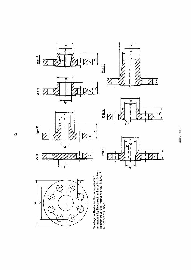
42
CO
PY
RIG
HT
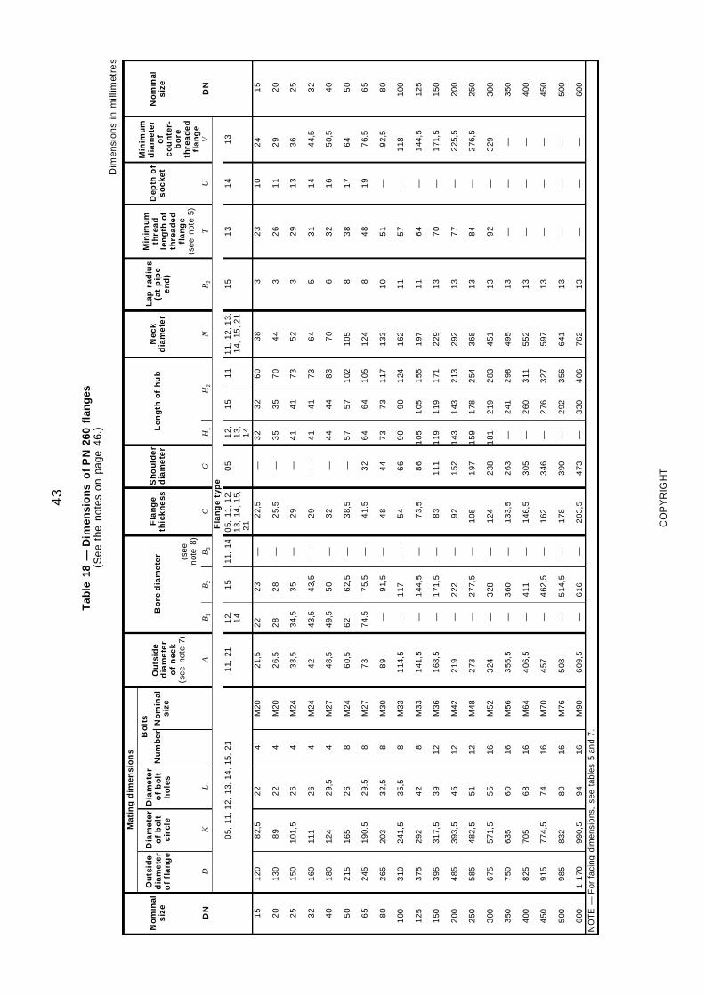
43
Tab
le18
—D
imen
sio
ns
of
PN
260
flan
ges
(Se
eth
eno
tes
on
page
46.
)D
imen
sion
sin
mill
imet
res
Mat
ing
dim
ensi
on
s
No
min
als
ize
Ou
tsid
ed
iam
ete
ro
ffl
an
ge
Dia
me
ter
of
bo
ltc
ircl
e
Dia
me
ter
of
bo
lth
ole
s
Bo
lts
Ou
tsid
ed
iam
ete
ro
fn
eck
(see
note
7)
Bo
red
iam
ete
rF
lan
ge
thic
kn
ess
Sh
ou
lde
rd
iam
ete
rL
eng
tho
fh
ub
Nec
kd
iam
ete
r
Lap
rad
ius
(at
pip
ee
nd
)
Min
imu
mth
rea
dle
ng
tho
fth
rea
de
dfl
an
ge
(see
note
5)
Dep
tho
fs
oc
ket
Min
imu
md
iam
ete
ro
fc
ou
nte
r-b
ore
thre
ad
ed
fla
ng
e
No
min
als
ize
Nu
mb
er
No
min
als
ize
(see
not
e8)
DN
DK
LA
B1
B2
B3
CG
H1
H2
NR
2T
UV
DN
Fla
ng
ety
pe
05,
11,1
2,1
3,14
,15
,21
11,
211
2, 14
15
11,
140
5,11
,12,
13,
14,1
5,2
1
05
12,
13, 14
15
11
11,
12,1
3,1
4,15
,21
15
13
14
13
15
20
25
32
40
50
65
80
100
125
150
200
250
300
350
400
450
500
600
120
130
150
160
180
215
245
265
310
375
395
485
585
675
750
825
915
985
11
70
82,
5
89
101
,5
111
124
165
190
,5
203
241
,5
292
317
,5
393
,5
482
,5
571
,5
635
705
774
,5
832
990
,5
22
22
26
26
29,
5
26
29,
5
32,
5
35,
5
42
39
45
51
55
60
68
74
80
94
4 4 4 4 4 8 8 8 8 8
12
12
12
16
16
16
16
16
16
M20
M20
M24
M24
M27
M24
M27
M30
M33
M33
M36
M42
M48
M52
M56
M64
M70
M76
M90
21,
5
26,
5
33,
5
42
48,
5
60,
5
73
89
114
,5
141
,5
168
,5
219
273
324
355
,5
406
,5
457
508
609
,5
22
28
34,
5
43,
5
49,
5
62
74,
5
— — — — — — — — — — — —
23
28
35
43,
5
50
62,
5
75,
5
91,
5
117
144
,5
171
,5
222
277
,5
328
360
411
462
,5
514
,5
616
— — — — — — — — — — — — — — — — — — —
22,
5
25,
5
29
29
32
38,
5
41,
5
48
54
73,
5
83
92
108
124
133
,5
146
,5
162
178
203
,5
— — — — — — 32
44
66
86
111
152
197
238
263
305
346
390
473
32
35
41
41
44
57
64
73
90
105
119
143
159
181 — — — — —
32
35
41
41
44
57
64
73
90
105
119
143
178
219
241
260
276
292
330
60
70
73
73
83
102
105
117
124
155
171
213
254
283
298
311
327
356
406
38
44
52
64
70
105
124
133
162
197
229
292
368
451
495
552
597
641
762
3 3 3 5 6 8 8
10
11
11
13
13
13
13
13
13
13
13
13
23
26
29
31
32
38
48
51
57
64
70
77
84
92 — — — — —
10
11
13
14
16
17
19 — — — — — — — — — — — —
24
29
36
44,
5
50,
5
64
76,
5
92,
5
118
144
,5
171
,5
225
,5
276
,5
329 — — — — —
15
20
25
32
40
50
65
80
100
125
150
200
250
300
350
400
450
500
600
NO
TE
—F
orfa
cin
gdi
men
sio
ns,
see
tab
les
5an
d7
.
CO
PY
RIG
HT
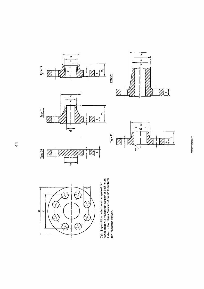
44
CO
PY
RIG
HT
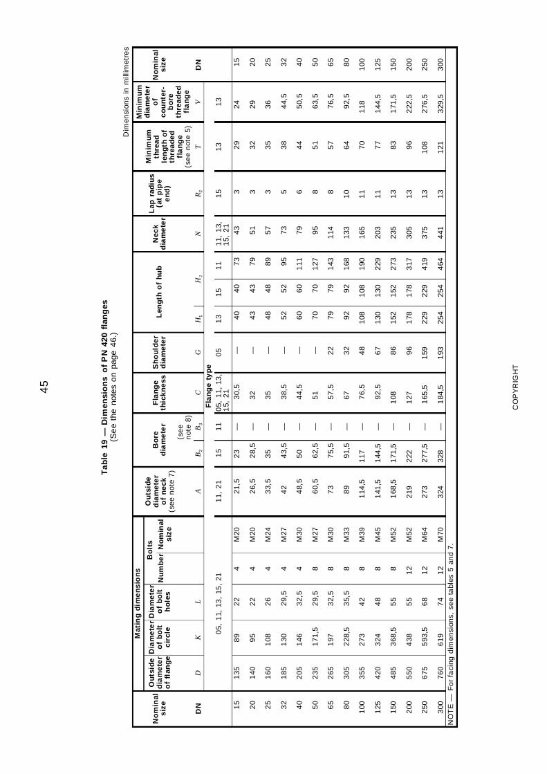
45
Tab
le19
—D
imen
sio
ns
of
PN
420
flan
ges
(Se
eth
eno
tes
on
page
46.
)
Dim
ensi
ons
inm
illim
etre
s
Mat
ing
dim
en
sio
ns
Min
imu
md
iam
ete
ro
fc
ou
nte
r-b
ore
thre
aded
fla
ng
e
No
min
als
ize
Ou
tsid
ed
iam
ete
ro
ffl
ang
e
Dia
me
ter
of
bo
ltc
ircl
e
Dia
me
ter
of
bo
lth
ole
s
Bo
lts
Ou
tsid
ed
iam
ete
ro
fn
eck
(se
en
ote
7)
Bo
red
iam
ete
rF
lan
ge
thic
knes
sS
ho
uld
erd
iam
ete
rL
eng
tho
fh
ub
Nec
kd
iam
ete
r
Lap
rad
ius
(at
pip
ee
nd
)
Min
imu
mth
read
len
gth
of
thre
aded
fla
ng
e(s
ee
not
e5
)
No
min
als
ize
Nu
mb
erN
om
inal
siz
e
(se
en
ote
8)
DN
DK
LA
B2
B3
CG
H1
H2
NR
2T
VD
NF
lan
ge
typ
e0
5,1
1,13
,15
,21
11,
21
15
11
05,
11,
13,
15,
21
05
13
15
11
11,
13,
15,
21
15
13
13
15
20
25
32
40
50
65
80
100
125
150
200
250
300
135
140
160
185
205
235
265
305
355
420
485
550
675
760
89
95
108
130
146
171
,5
197
228
,5
273
324
368
,5
438
593
,5
619
22
22
26
29,
5
32,
5
29,
5
32,
5
35,
5
42
48
55
55
68
74
4 4 4 4 4 8 8 8 8 8 8 12
12
12
M20
M20
M24
M27
M30
M27
M30
M33
M39
M45
M52
M52
M64
M70
21,
5
26,
5
33,
5
42
48,
5
60,
5
73
89
114
,5
141
,5
168
,5
219
273
324
23
28,
5
35
43,
5
50
62,
5
75,
5
91,
5
117
144
,5
171
,5
222
277
,5
328
— — — — — — — — — — — — — —
30,
5
32
35
38,
5
44,
5
51
57,
5
67
76,
5
92,
5
108
127
165
,5
184
,5
— — — — — — 22
32
48
67
86
96
159
193
40
43
48
52
60
70
79
92
108
130
152
178
229
254
40
43
48
52
60
70
79
92
108
130
152
178
229
254
73
79
89
95
111
127
143
168
190
229
273
317
419
464
43
51
57
73
79
95
114
133
165
203
235
305
375
441
3 3 3 5 6 8 8
10
11
11
13
13
13
13
29
32
35
38
44
51
57
64
70
77
83
96
108
121
24
29
36
44,
5
50,
5
63,
5
76,
5
92,
5
118
144
,5
171
,5
222
,5
276
,5
329
,5
15
20
25
32
40
50
65
80
100
125
150
200
250
300
NO
TE
—F
or
faci
ngd
imen
sion
s,se
eta
bles
5an
d7.
CO
PY
RIG
HT
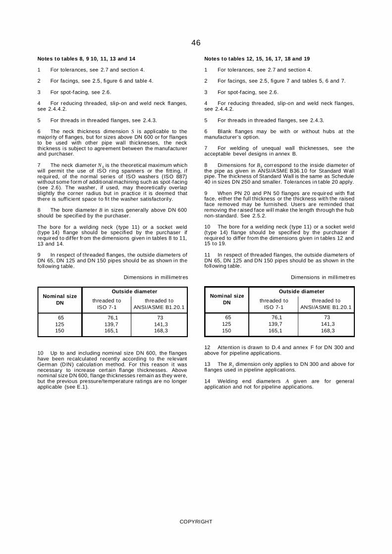
46
Notes to tables 8, 9 10, 11, 13 and 14
1 For tolerances, see 2.7 and section 4.
2 For facings, see 2.5, figure 6 and table 4.
3 For spot-facing, see 2.6.
4 For reducing threaded, slip-on and weld neck flanges,see 2.4.4.2.
5 For threads in threaded flanges, see 2.4.3.
6 The neck thickness dimension S is applicable to themajori ty of flanges, but for sizes above DN 600 or for flangesto be used with other pipe wall thicknesses, the neckthickness is subject to agreement between the manufacturerand purchaser.
7 The neck diameter N 3 is the theoretical maximum whichwill permit the use of ISO ring spanners or the fi tt ing, ifrequired, of the normal series of ISO washers (ISO 887)without some form of additional machining such as spot-facing(see 2.6). The washer, if used, may theoretically overlapslightly the corner radius but in practice it is deemed thatthere is suff icient space to fi t the washer satisfactorily.
8 The bore diameter B in sizes generally above DN 600should be specif ied by the purchaser.
The bore for a welding neck (type 11) or a socket weld(type 14) flange should be specified by the purchaser ifrequired to dif fer from the dimensions given in tables 8 to 11,13 and 14.
9 In respect of threaded flanges, the outside diameters ofDN 65, DN 125 and DN 150 pipes should be as shown in thefollowing table.
Dimensions in mil limetres
Nominal sizeDN
Outside diameter
threaded toISO 7-1
threaded toANSI/ASME B1.20.1
65125150
76,1139,7165,1
73141,3168,3
10 Up to and including nominal size DN 600, the flangeshave been recalculated recently according to the relevantGerman (DIN) calculation method. For this reason it wasnecessary to increase certain flange thicknesses. Abovenominal size DN 600, flange thicknesses remain as they were,but the previous pressure/temperature ratings are no longerapplicable (see E.1).
Notes to tables 12, 15, 16, 17, 18 and 19
1 For tolerances, see 2.7 and section 4.
2 For facings, see 2.5, figure 7 and tables 5, 6 and 7.
3 For spot-facing, see 2.6.
4 For reducing threaded, slip-on and weld neck flanges,see 2.4.4.2.
5 For threads in threaded flanges, see 2.4.3.
6 Blank flanges may be with or without hubs at themanufacturer’s option.
7 For welding of unequal wall thicknesses, see theacceptable bevel designs in annex B.
8 Dimensions for B3 correspond to the inside diameter ofthe pipe as given in ANSI/ASME B36.10 for Standard Wallpipe. The thickness of Standard Wall is the same as Schedule40 in sizes DN 250 and smaller. Tolerances in table 20 apply.
9 When PN 20 and PN 50 flanges are required with flatface, either the full thickness or the thickness with the raisedface removed may be furnished. Users are reminded thatremoving the raised face wil l make the length through the hubnon-standard. See 2.5.2.
10 The bore for a welding neck (type 11) or a socket weld(type 14) flange should be specif ied by the purchaser ifrequired to differ from the dimensions given in tables 12 and15 to 19.
11 In respect of threaded flanges, the outside diameters ofDN 65, DN 125 and DN 150 pipes should be as shown in thefollowing table.
Dimensions in mil limetres
12 Attention is drawn to D.4 and annex F for DN 300 and
Nominal sizeDN
Outside diameter
threaded toISO 7-1
threaded toANSI/ASME B1.20.1
65125150
76,1139,7165,1
73141,3168,3
above for pipeline applications.
13 The R1 dimension only applies to DN 300 and above forflanges used in pipeline applications.
14 Welding end diameters A given are for generalapplication and not for pipeline applications.
COPYRIGHT
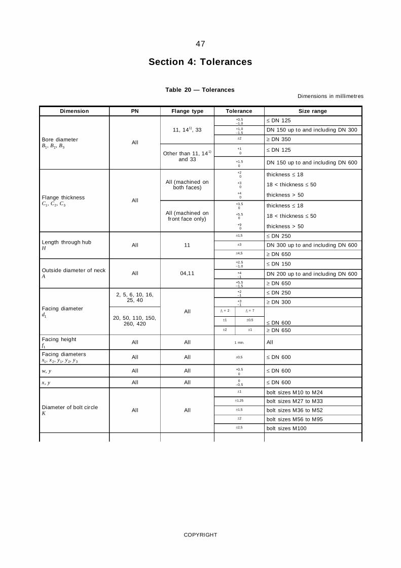
47
Section 4: Tolerances
Table 20 — TolerancesDimensions in mil limetres
Dimension PN Flange type Tolerance Size range
Bore diameterB1, B2, B3
All
11, 141), 33
+0,5−1,0
≤ DN 125+1,0−1,5
DN 150 up to and including DN 300±2 ≥ DN 350
Other than 11, 141)
and 33
+10
≤ DN 125
+1,50
DN 150 up to and including DN 600
Flange thicknessC1, C2, C3
All
All (machined onboth faces)
+20 thickness ≤ 18
+30 18 < thickness ≤ 50
+40 thickness > 50
All (machined onfront face only)
+3,50 thickness ≤ 18
+5,50 18 < thickness ≤ 50
+90 thickness > 50
Length through hubH All 11
±1,5 ≤ DN 250±3 DN 300 up to and including DN 600
±4,5 ≥ DN 650
Outside diameter of neckA All 04,11
+2,5−1,0 ≤ DN 150
+4−1
DN 200 up to and including DN 600+5,5−1,5 ≥ DN 650
Facing diameterd1
2, 5, 6, 10, 16,25, 40
All
+2−1 ≤ DN 250+3−1 ≥ DN 300
20, 50, 110, 150,260, 420
f1 = 2 f1 = 7
≤ DN 600±1 ±0,5
±2 ±1 ≥ DN 650
Facing heightf1
All All 1 min. All
Facing diametersx1, x2, y1, y2, y3
All All ±0,5 ≤ DN 600
w, y All All +0,50
≤ DN 600
x, y All All 0−0,5 ≤ DN 600
Diameter of bolt circleK All All
±1 bolt sizes M10 to M24±1,25 bolt sizes M27 to M33±1,5 bolt sizes M36 to M52±2 bolt sizes M56 to M95
±2,5 bolt sizes M100
COPYRIGHT
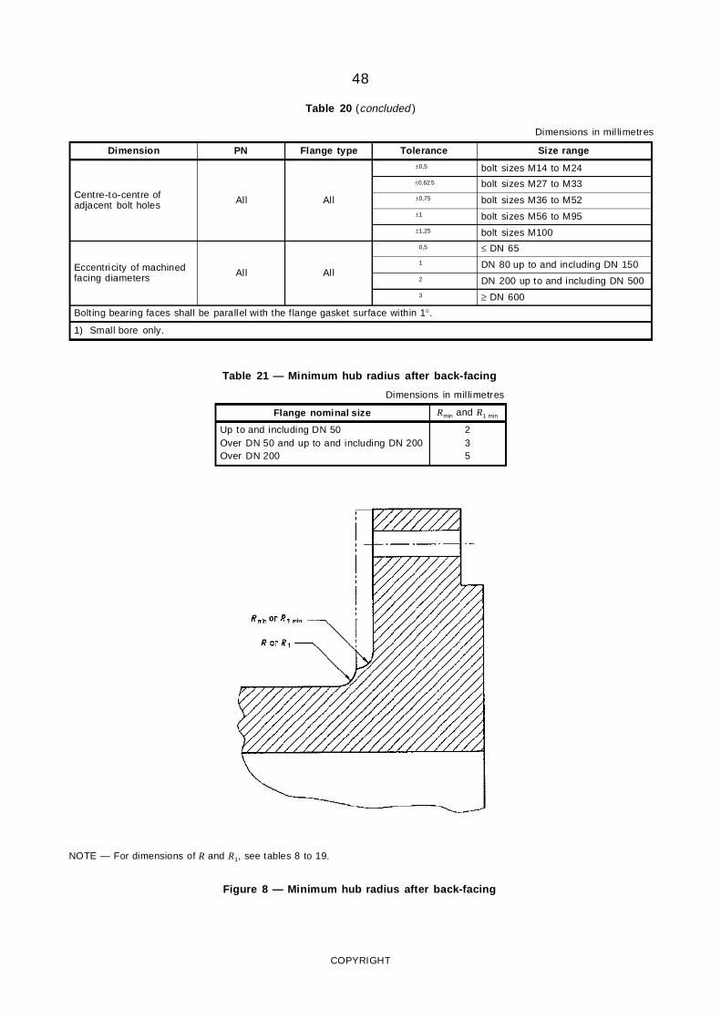
48
Table 20 (concluded )
Dimensions in mil limetres
Dimension PN Flange type Tolerance Size range
Centre-to-centre ofadjacent bolt holes All All
±0,5 bolt sizes M14 to M24±0,62 5 bolt sizes M27 to M33±0,75 bolt sizes M36 to M52±1 bolt sizes M56 to M95±1,25 bolt sizes M100
Eccentricity of machinedfacing diameters All All
0,5 ≤ DN 651 DN 80 up to and including DN 1502 DN 200 up to and including DN 5003 ≥ DN 600
Bolt ing bearing faces shall be parallel with the flange gasket surface within 1°.
1) Small bore only.
Table 21 — Minimum hub radius after back-facing
Dimensions in mil limetres
Flange nominal size Rmin and R1 min
Up to and including DN 50Over DN 50 and up to and including DN 200Over DN 200
235
NOTE — For dimensions of R and R1, see tables 8 to 19.
Figure 8 — Minimum hub radius after back-facing
COPYRIGHT
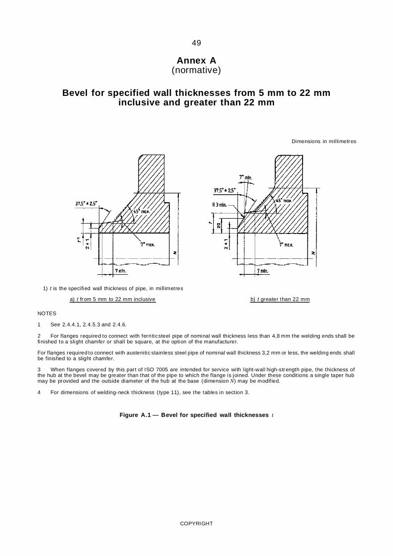
49
Annex A(normative)
Bevel for specified wall thicknesses from 5 mm to 22 mminclusive and greater than 22 mm
Dimensions in mil limetres
1) t is the specified wall thickness of pipe, in mill imetres
a) t from 5 mm to 22 mm inclusive b) t greater than 22 mm
NOTES
1 See 2.4.4.1, 2.4.5.3 and 2.4.6.
2 For flanges required to connect with ferri ticsteel pipe of nominal wall thickness less than 4,8 mm the welding ends shall befinished to a slight chamfer or shall be square, at the option of the manufacturer.
For flanges required to connect with austenitic stainless steel pipe of nominal wall thickness 3,2 mm or less, the welding ends shallbe finished to a slight chamfer.
3 When flanges covered by this part of ISO 7005 are intended for service with light-wall high-strength pipe, the thickness ofthe hub at the bevel may be greater than that of the pipe to which the flange is joined. Under these condit ions a single taper hubmay be provided and the outside diameter of the hub at the base (dimension N) may be modif ied.
4 For dimensions of welding-neck thickness (type 11), see the tables in section 3.
Figure A.1 — Bevel for specified wall thicknesses t
COPYRIGHT
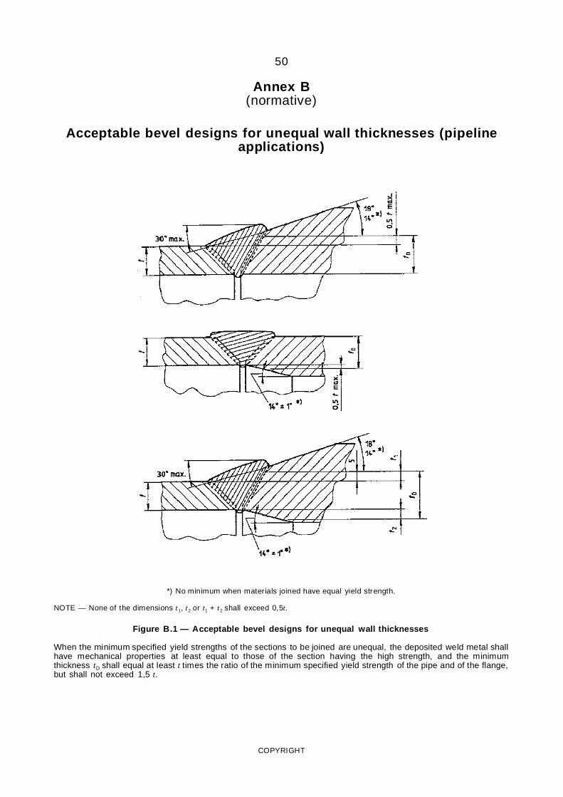
50
Annex B(normative)
Acceptable bevel designs for unequal wall thicknesses (pipelineapplications)
*) No minimum when materials joined have equal yield strength.
NOTE — None of the dimensions t1, t2 or t1 + t2 shall exceed 0,5t.
Figure B.1 — Acceptable bevel designs for unequal wall thicknesses
When the minimum specified yield strengths of the sections to be joined are unequal, the deposited weld metal shallhave mechanical properties at least equal to those of the section having the high strength, and the minimumthickness tD shall equal at least t times the ratio of the minimum specified yield strength of the pipe and of the flange,but shall not exceed 1,5 t.
COPYRIGHT
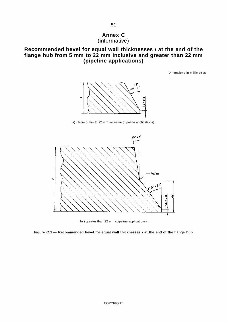
51
Annex C(informative)
Recommended bevel for equal wall thicknesses t at the end of theflange hub from 5 mm to 22 mm inclusive and greater than 22 mm
(pipeline applications)
Dimensions in mil limetres
a) t from 5 mm to 22 mm inclusive (pipeline applications)
b) t greater than 22 mm (pipeline applications)
Figure C.1 — Recommended bevel for equal wall thicknesses t at the end of the flange hub
COPYRIGHT
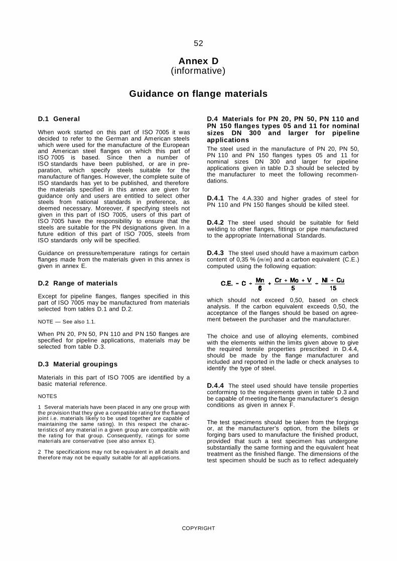
52
Annex D(informative)
Guidance on flange materials
D.1 General
When work started on this part of ISO 7005 it wasdecided to refer to the German and American steelswhich were used for the manufacture of the Europeanand American steel flanges on which this part ofISO 7005 is based. Since then a number ofISO standards have been published, or are in pre-paration, which specify steels suitable for themanufacture of flanges. However, the complete suite ofISO standards has yet to be published, and thereforethe materials specified in this annex are given forguidance only and users are entitled to select othersteels from national standards in preference, asdeemed necessary. Moreover, if specifying steels notgiven in this part of ISO 7005, users of this part ofISO 7005 have the responsibility to ensure that thesteels are suitable for the PN designations given. In afuture edition of this part of ISO 7005, steels fromISO standards only will be specified.
Guidance on pressure/temperature ratings for certainflanges made from the materials given in this annex isgiven in annex E.
D.2 Range of materials
Except for pipeline flanges, flanges specified in thispart of ISO 7005 may be manufactured from materialsselected from tables D.1 and D.2.
NOTE — See also 1.1.
When PN 20, PN 50, PN 110 and PN 150 flanges arespecified for pipeline applications, materials may beselected from table D.3.
D.3 Material groupings
Materials in this part of ISO 7005 are identified by abasic material reference.
NOTES
1 Several materials have been placed in any one group withthe provision that they give a compatible rating for the flangedjoint i.e. materials likely to be used together are capable ofmaintaining the same rating). In this respect the charac-teristics of any material in a given group are compatible withthe rating for that group. Consequently, ratings for somematerials are conservative (see also annex E).
2 The specif ications may not be equivalent in all details andtherefore may not be equally suitable for all applications.
D.4 Materials for PN 20, PN 50, PN 110 andPN 150 flanges types 05 and 11 for nominalsizes DN 300 and larger for pipelineapplicationsThe steel used in the manufacture of PN 20, PN 50,PN 110 and PN 150 flanges types 05 and 11 fornominal sizes DN 300 and larger for pipelineapplications given in table D.3 should be selected bythe manufacturer to meet the following recommen-dations.
D.4.1 The 4.A.330 and higher grades of steel forPN 110 and PN 150 flanges should be killed steel.
D.4.2 The steel used should be suitable for fieldwelding to other flanges, fittings or pipe manufacturedto the appropriate International Standards.
D.4.3 The steel used should have a maximum carboncontent of 0,35 % (m/m) and a carbon equivalent (C.E.)computed using the following equation:
which should not exceed 0,50, based on checkanalysis. If the carbon equivalent exceeds 0,50, theacceptance of the flanges should be based on agree-ment between the purchaser and the manufacturer.
The choice and use of alloying elements, combinedwith the elements within the limits given above to givethe required tensile properties prescribed in D.4.4,should be made by the flange manufacturer andincluded and reported in the ladle or check analyses toidentify the type of steel.
D.4.4 The steel used should have tensile propertiesconforming to the requirements given in table D.3 andbe capable of meeting the flange manufacturer’s designconditions as given in annex F.
The test specimens should be taken from the forgingsor, at the manufacturer’s option, from the billets orforging bars used to manufacture the finished product,provided that such a test specimen has undergonesubstantially the same forming and the equivalent heattreatment as the finished flange. The dimensions of thetest specimen should be such as to reflect adequately
COPYRIGHT
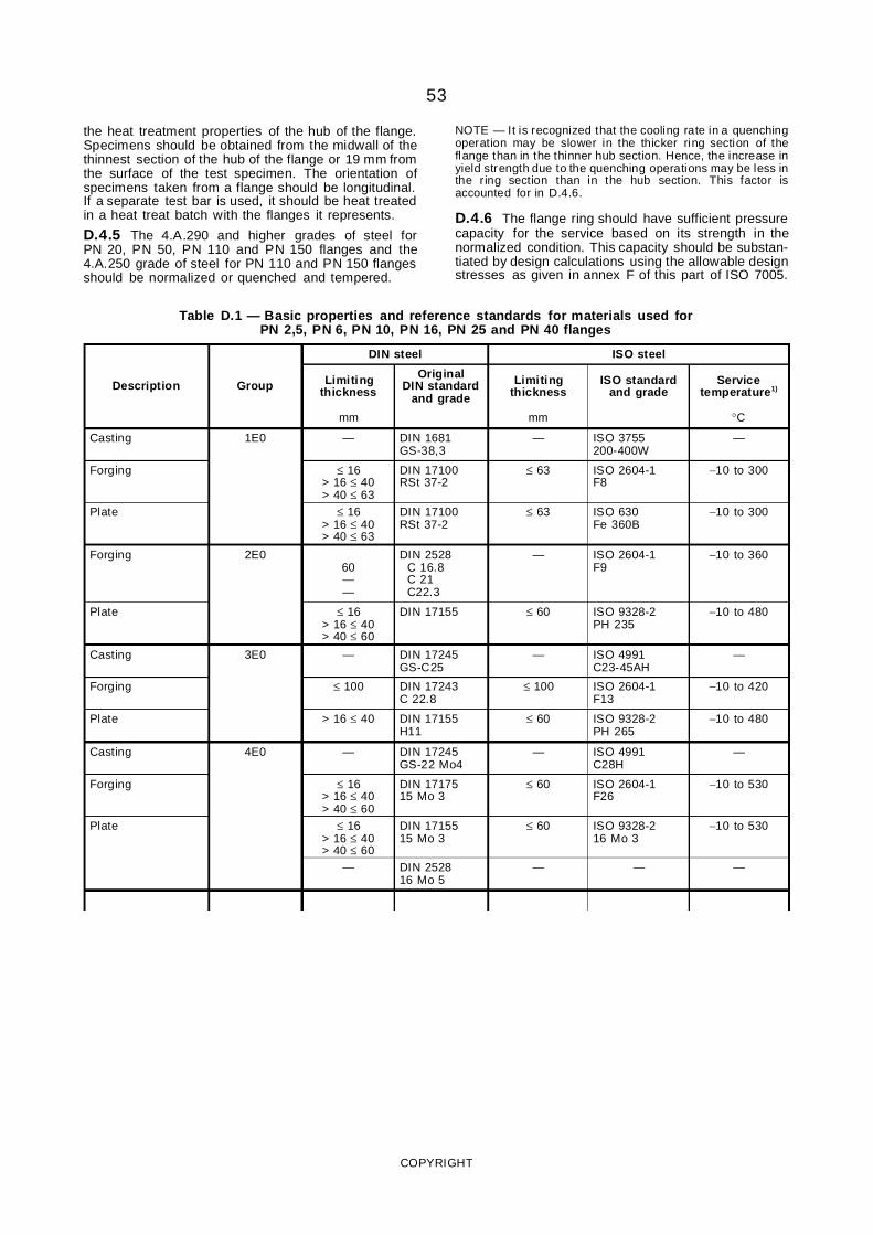
53
the heat treatment properties of the hub of the flange.Specimens should be obtained from the midwall of thethinnest section of the hub of the flange or 19 mm fromthe surface of the test specimen. The orientation ofspecimens taken from a flange should be longitudinal.If a separate test bar is used, it should be heat treatedin a heat treat batch with the flanges it represents.
D.4.5 The 4.A.290 and higher grades of steel forPN 20, PN 50, PN 110 and PN 150 flanges and the4.A.250 grade of steel for PN 110 and PN 150 flangesshould be normalized or quenched and tempered.
NOTE — It is recognized that the cooling rate in a quenchingoperation may be slower in the thicker ring section of theflange than in the thinner hub section. Hence, the increase inyield strength due to the quenching operations may be less inthe ring section than in the hub section. This factor isaccounted for in D.4.6.
D.4.6 The flange ring should have sufficient pressurecapacity for the service based on its strength in thenormalized condition. This capacity should be substan-tiated by design calculations using the allowable designstresses as given in annex F of this part of ISO 7005.
Table D.1 — Basic properties and reference standards for materials used forPN 2,5, PN 6, PN 10, PN 16, PN 25 and PN 40 flanges
DIN steel ISO steel
Description Group Limitingthickness
OriginalDIN standard
and grade
Limitingthickness
ISO standardand grade
Servicetemperature1)
mm mm °C
Casting 1E0 — DIN 1681GS-38,3
— ISO 3755200-400W
—
Forging ≤ 16> 16 ≤ 40> 40 ≤ 63
DIN 17100RSt 37-2
≤ 63 ISO 2604-1F8
−10 to 300
Plate ≤ 16> 16 ≤ 40> 40 ≤ 63
DIN 17100RSt 37-2
≤ 63 ISO 630Fe 360B
−10 to 300
Forging 2E060——
DIN 2528C 16.8C 21C22.3
— ISO 2604-1F9
−10 to 360
Plate ≤ 16> 16 ≤ 40> 40 ≤ 60
DIN 17155 ≤ 60 ISO 9328-2PH 235
−10 to 480
Casting 3E0 — DIN 17245GS-C25
— ISO 4991C23-45AH
—
Forging ≤ 100 DIN 17243C 22.8
≤ 100 ISO 2604-1F13
−10 to 420
Plate > 16 ≤ 40 DIN 17155H11
≤ 60 ISO 9328-2PH 265
−10 to 480
Casting 4E0 — DIN 17245GS-22 Mo4
— ISO 4991C28H
—
Forging ≤ 16> 16 ≤ 40> 40 ≤ 60
DIN 1717515 Mo 3
≤ 60 ISO 2604-1F26
−10 to 530
Plate ≤ 16> 16 ≤ 40> 40 ≤ 60
DIN 1715515 Mo 3
≤ 60 ISO 9328-216 Mo 3
−10 to 530
— DIN 252816 Mo 5
— — —
COPYRIGHT
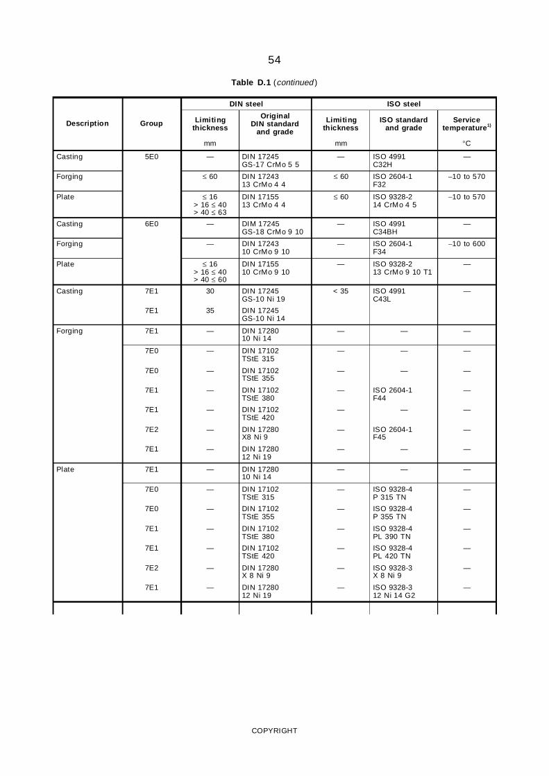
54
Table D.1 (continued )
DIN steel ISO steel
Description Group Limitingthickness
OriginalDIN standard
and grade
Limitingthickness
ISO standardand grade
Servicetemperature1)
mm mm °C
Casting 5E0 — DIN 17245GS-17 CrMo 5 5
— ISO 4991C32H
—
Forging ≤ 60 DIN 1724313 CrMo 4 4
≤ 60 ISO 2604-1F32
−10 to 570
Plate ≤ 16> 16 ≤ 40> 40 ≤ 63
DIN 1715513 CrMo 4 4
≤ 60 ISO 9328-214 CrMo 4 5
−10 to 570
Casting 6E0 — DIM 17245GS-18 CrMo 9 10
— ISO 4991C34BH
—
Forging — DIN 1724310 CrMo 9 10
— ISO 2604-1F34
−10 to 600
Plate ≤ 16> 16 ≤ 40> 40 ≤ 60
DIN 1715510 CrMo 9 10
— ISO 9328-213 CrMo 9 10 T1
—
Casting 7E1 30 DIN 17245GS-10 Ni 19
< 35 ISO 4991C43L
—
7E1 35 DIN 17245GS-10 Ni 14
Forging 7E1 — DIN 1728010 Ni 14
— — —
7E0 — DIN 17102TStE 315
— — —
7E0 — DIN 17102TStE 355
— — —
7E1 — DIN 17102TStE 380
— ISO 2604-1F44
—
7E1 — DIN 17102TStE 420
— — —
7E2 — DIN 17280X8 Ni 9
— ISO 2604-1F45
—
7E1 — DIN 1728012 Ni 19
— — —
Plate 7E1 — DIN 1728010 Ni 14
— — —
7E0 — DIN 17102TStE 315
— ISO 9328-4P 315 TN
—
7E0 — DIN 17102TStE 355
— ISO 9328-4P 355 TN
—
7E1 — DIN 17102TStE 380
— ISO 9328-4PL 390 TN
—
7E1 — DIN 17102TStE 420
— ISO 9328-4PL 420 TN
—
7E2 — DIN 17280X 8 Ni 9
— ISO 9328-3X 8 Ni 9
—
7E1 — DIN 1728012 Ni 19
— ISO 9328-312 Ni 14 G2
—
COPYRIGHT
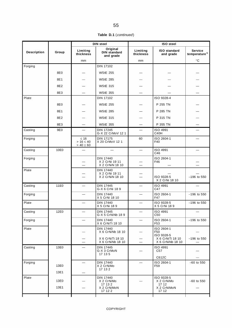
55
Table D.1 (continued )
DIN steel ISO steel
Description Group Limitingthickness
OriginalDIN standard
and grade
Limitingthickness
ISO standardand grade
Servicetemperature1)
mm mm °C
Forging
8E0
8E1
8E2
8E3
—
—
—
—
DIN 17102
WStE 255
WStE 285
WStE 315
WStE 355
—
—
—
—
—
—
—
—
—
—
—
—
Plate
8E0
8E1
8E2
8E3
—
—
—
—
DIN 17102
WStE 255
WStE 285
WStE 315
WStE 355
—
—
—
—
ISO 9328-4
P 255 TN
P 285 TN
P 315 TN
P 355 TN
—
—
—
—
Casting 9E0 — DIN 17245G-X 22 CrMoV 12 1
— ISO 4991C40H
—
Forging ≤ 16> 16 ≤ 40> 40 ≤ 60
DIN 17175X 20 CrMoV 12 1
60 ISO 2604-1F40
—
Casting 10E0 — — — ISO 4991C46
—
Forging——
DIN 17440X 2 CrNi 19 11X 2 CrNiN 18 10
——
ISO 2604-1F46
———
Plate——
DIN 17440X 2 CrNi 19 11X 2 CrNiN 18 10
——
—ISO 9328-5
X 2 CrNi 18 10
—−196 to 550
Casting 11E0 — DIN 17445G-X 6 CrNi 18 9
— ISO 4991C47
—
Forging — DIN 17440X 5 CrNi 18 10
— ISO 2604-1F47
−196 to 550
Plate — DIN 17440X 5 CrNi 18 9
— ISO 9328-5X 5 CrNi 18 9
−196 to 550
Casting 12E0 — DIN 17445G-X 5 CrNiNb 18 9
— ISO 4991C50
—
Forging — DIN 17440X 6 CrNiTi 18 10
— ISO 2604-1F53
−196 to 550
Plate—
——
DIN 17440X 6 CrNiNb 18 10
X 6 CrNiTi 18 10X 6 CrNiNb 18 10
—
——
ISO 2604-1F50ISO 9328-5
X 6 CrNiTi 18 10X 6 CrNiNb 18 10
—
−196 to 550—
Casting 13E0 — DIN 17445G-X 3 CrMoN
17 13 5—
ISO 4991C57
C612C
—
—
Forging13E0
13E1
—
—
DIN 17440X 2 CrNiMo
17 13 2
— ISO 2604-1F59
−60 to 550
Plate13E0
13E1
—
—
DIN 17440X 2 CrNiMo
17 13 2X 2 CrNiMoN
17 12 2
—ISO 9328-5
X 2 CrNiMo17 12
X 2 CrNiMoN17 12
−60 to 550
—
COPYRIGHT
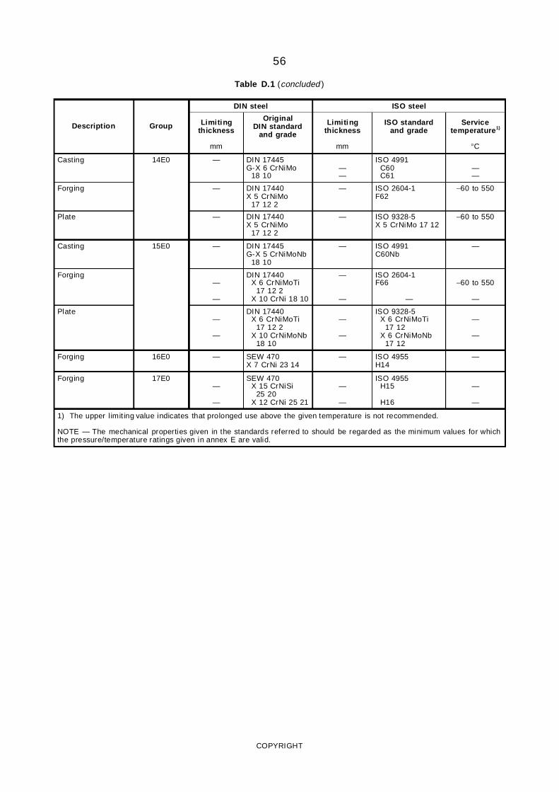
56
Table D.1 (concluded )
DIN steel ISO steel
Description Group Limitingthickness
OriginalDIN standard
and grade
Limitingthickness
ISO standardand grade
Servicetemperature1)
mm mm °C
Casting 14E0 — DIN 17445G-X 6 CrNiMo
18 10——
ISO 4991C60C61
——
Forging — DIN 17440X 5 CrNiMo
17 12 2
— ISO 2604-1F62
−60 to 550
Plate — DIN 17440X 5 CrNiMo
17 12 2
— ISO 9328-5X 5 CrNiMo 17 12
−60 to 550
Casting 15E0 — DIN 17445G-X 5 CrNiMoNb
18 10
— ISO 4991C60Nb
—
Forging—
—
DIN 17440X 6 CrNiMoTi
17 12 2X 10 CrNi 18 10
—
—
ISO 2604-1F66
—
−60 to 550
—
Plate—
—
DIN 17440X 6 CrNiMoTi
17 12 2X 10 CrNiMoNb
18 10
—
—
ISO 9328-5X 6 CrNiMoTi
17 12X 6 CrNiMoNb
17 12
—
—
Forging 16E0 — SEW 470X 7 CrNi 23 14
— ISO 4955H14
—
Forging 17E0—
—
SEW 470X 15 CrNiSi
25 20X 12 CrNi 25 21
—
—
ISO 4955H15
H16
—
—
1) The upper limit ing value indicates that prolonged use above the given temperature is not recommended.
NOTE — The mechanical properties given in the standards referred to should be regarded as the minimum values for whichthe pressure/temperature ratings given in annex E are valid.
COPYRIGHT
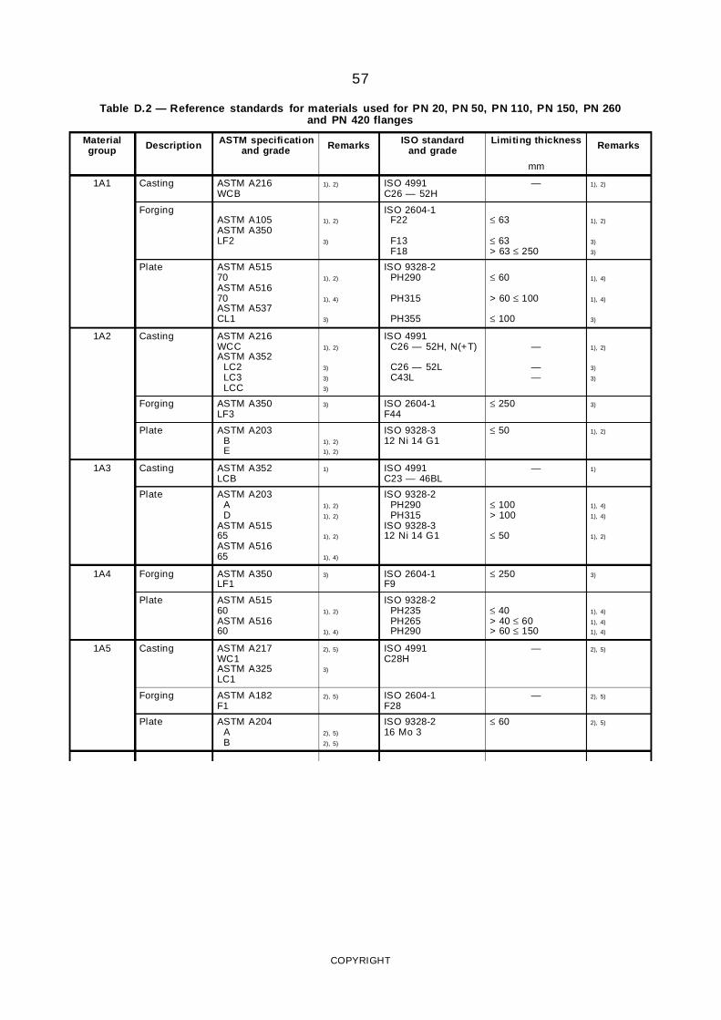
57
Table D.2 — Reference standards for materials used for PN 20, PN 50, PN 110, PN 150, PN 260and PN 420 flanges
Materialgroup Description ASTM specification
and grade Remarks ISO standardand grade
Limiting thickness Remarks
mm
1A1 Casting ASTM A216WCB
1), 2) ISO 4991C26 — 52H
— 1), 2)
ForgingASTM A105ASTM A350LF2
1), 2)
3)
ISO 2604-1F22
F13F18
≤ 63
≤ 63> 63 ≤ 250
1), 2)
3)
3)
Plate ASTM A51570ASTM A51670ASTM A537CL1
1), 2)
1), 4)
3)
ISO 9328-2PH290
PH315
PH355
≤ 60
> 60 ≤ 100
≤ 100
1), 4)
1), 4)
3)
1A2 Casting ASTM A216WCCASTM A352
LC2LC3LCC
1), 2)
3)
3)
3)
ISO 4991C26 — 52H, N(+T)
C26 — 52LC43L
—
——
1), 2)
3)
3)
Forging ASTM A350LF3
3) ISO 2604-1F44
≤ 250 3)
Plate ASTM A203BE
1), 2)
1), 2)
ISO 9328-312 Ni 14 G1
≤ 50 1), 2)
1A3 Casting ASTM A352LCB
1) ISO 4991C23 — 46BL
— 1)
Plate ASTM A203AD
ASTM A51565ASTM A51665
1), 2)
1), 2)
1), 2)
1), 4)
ISO 9328-2PH290PH315
ISO 9328-312 Ni 14 G1
≤ 100> 100
≤ 50
1), 4)
1), 4)
1), 2)
1A4 Forging ASTM A350LF1
3) ISO 2604-1F9
≤ 250 3)
Plate ASTM A51560ASTM A51660
1), 2)
1), 4)
ISO 9328-2PH235PH265PH290
≤ 40> 40 ≤ 60> 60 ≤ 150
1), 4)
1), 4)
1), 4)
1A5 Casting ASTM A217WC1ASTM A325LC1
2), 5)
3)
ISO 4991C28H
— 2), 5)
Forging ASTM A182F1
2), 5) ISO 2604-1F28
— 2), 5)
Plate ASTM A204AB
2), 5)
2), 5)
ISO 9328-216 Mo 3
≤ 60 2), 5)
COPYRIGHT
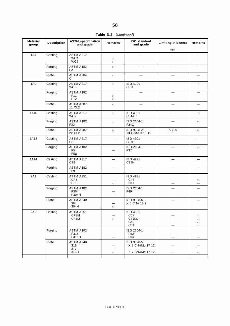
58
Table D.2 (continued )
Materialgroup Description ASTM specification
and grade Remarks ISO standardand grade Limiting thickness Remarks
mm
1A7 Casting ASTM A217WC4WC5
2)
6)
— — —
Forging ASTM A182F2
2) — — —
Plate ASTM A204C
4) — — —
1A9 Casting ASTM A217WC6
7) ISO 4991C32H
— 7)
Forging ASTM A182F11F12
8)
8)
— — —
Plate ASTM A38711 CL2
8) — — —
1A10 Casting ASTM A217WC9
7) ISO 4991C34AH
— 7)
Forging ASTM A182F22
7) ISO 2604-1F34Q
— 8)
Plate ASTM A38722 CL2
8) ISO 9328-213 CrMo 9 10 T2
≤ 100 8)
1A13 Casting ASTM A217C5
— ISO 4991C37H
— —
Forging ASTM A182F5F5a
——
ISO 2604-1F37
— —
1A14 Casting ASTM A217C12
— ISO 4991C38H
— —
Forging ASTM A182F9
— — — —
2A1 Casting ASTM A351CF8CF3
—9)
ISO 4991C46C47
——
9)
—
Forging ASTM A182F304F304H
——
ISO 2604-1F49
— —
Plate ASTM A240304304H
—9)
ISO 9328-5X 5 CrNi 18 9
— —
2A2 Casting ASTM A351CF8MCF3M
—4)
ISO 4991C57C61LCC60C61
————
4)
4)
4)
4)
Forging ASTM A182F316F316H
——
ISO 2604-1F62F64
——
——
Plate ASTM A240316317316H
——4)
ISO 9328-5X 5 CrNiMo 17 12
—X 7 CrNiMo 17 12
———
——4)
COPYRIGHT
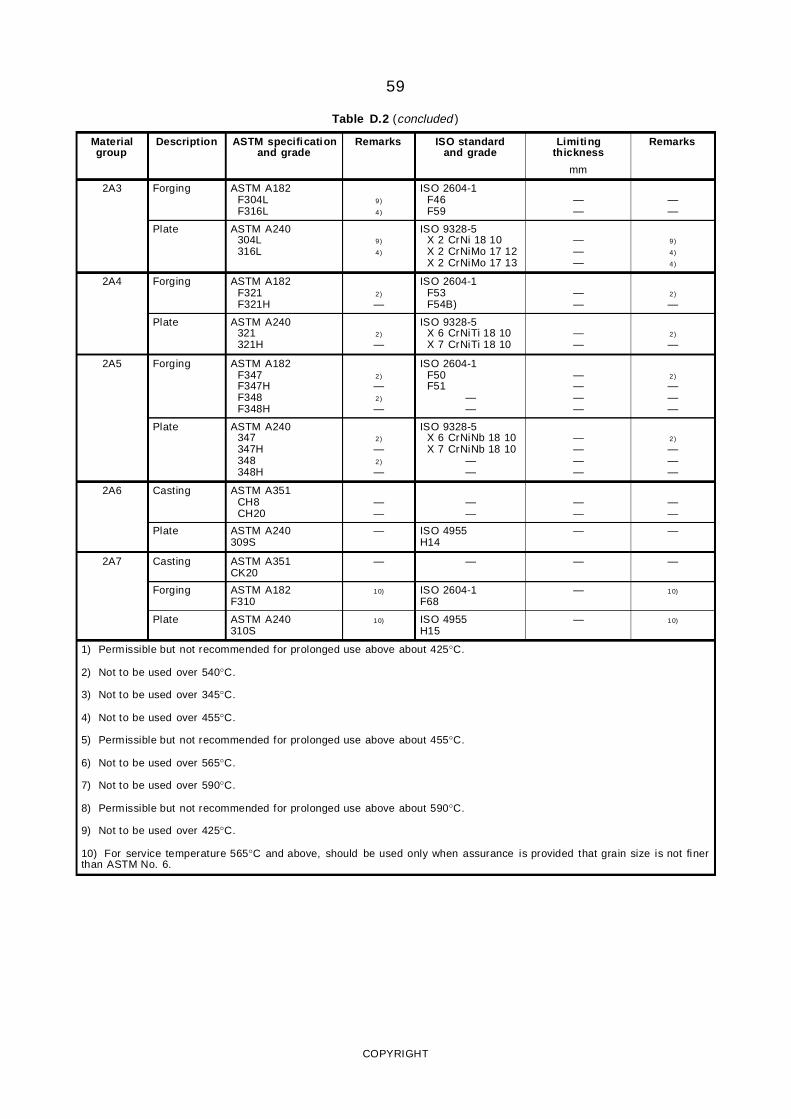
59
Table D.2 (concluded )
Materialgroup
Description ASTM specificationand grade
Remarks ISO standardand grade
Limitingthickness
Remarks
mm
2A3 Forging ASTM A182F304LF316L
9)
4)
ISO 2604-1F46F59
——
——
Plate ASTM A240304L316L
9)
4)
ISO 9328-5X 2 CrNi 18 10X 2 CrNiMo 17 12X 2 CrNiMo 17 13
———
9)
4)
4)
2A4 Forging ASTM A182F321F321H
2)
—
ISO 2604-1F53F54B)
——
2)
—
Plate ASTM A240321321H
2)
—
ISO 9328-5X 6 CrNiTi 18 10X 7 CrNiTi 18 10
——
2)
—
2A5 Forging ASTM A182F347F347HF348F348H
2)
—2)
—
ISO 2604-1F50F51
——
————
2)
———
Plate ASTM A240347347H348348H
2)
—2)
—
ISO 9328-5X 6 CrNiNb 18 10X 7 CrNiNb 18 10
——
————
2)
———
2A6 Casting ASTM A351CH8CH20
——
——
——
——
Plate ASTM A240309S
— ISO 4955H14
— —
2A7 Casting ASTM A351CK20
— — — —
Forging ASTM A182F310
10) ISO 2604-1F68
— 10)
Plate ASTM A240310S
10) ISO 4955H15
— 10)
1) Permissible but not recommended for prolonged use above about 425°C.
2) Not to be used over 540°C.
3) Not to be used over 345°C.
4) Not to be used over 455°C.
5) Permissible but not recommended for prolonged use above about 455°C.
6) Not to be used over 565°C.
7) Not to be used over 590°C.
8) Permissible but not recommended for prolonged use above about 590°C.
9) Not to be used over 425°C.
10) For service temperature 565°C and above, should be used only when assurance is provided that grain size is not finerthan ASTM No. 6.
COPYRIGHT
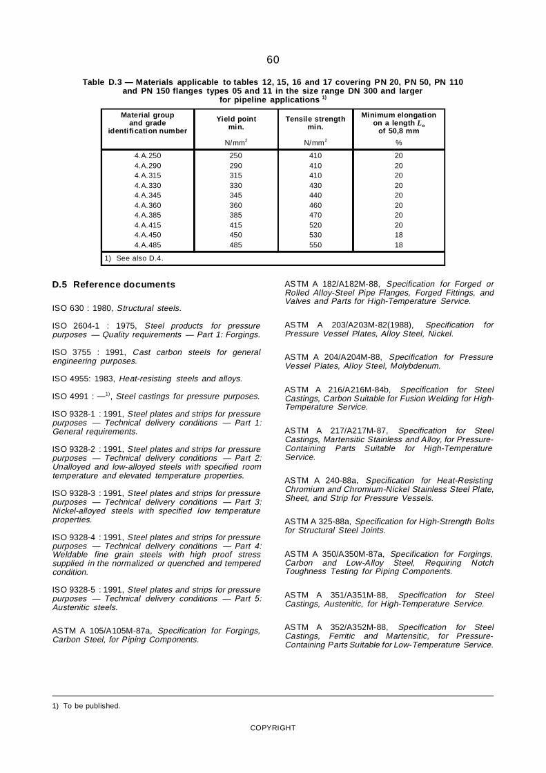
60
Table D.3 — Materials applicable to tables 12, 15, 16 and 17 covering PN 20, PN 50, PN 110and PN 150 flanges types 05 and 11 in the size range DN 300 and larger
for pipeline applications 1)
Material groupand grade
identi fication number
Yield pointmin.
Tensile strengthmin.
Minimum elongationon a length Lo
of 50,8 mm
N/mm2 N/mm2 %
4.A.2504.A.2904.A.3154.A.3304.A.3454.A.3604.A.3854.A.4154.A.4504.A.485
250290315330345360385415450485
410410410430440460470520530550
20202020202020201818
1) See also D.4.
D.5 Reference documents
ISO 630 : 1980, Structural steels.
ISO 2604-1 : 1975, Steel products for pressurepurposes — Quality requirements — Part 1: Forgings.
ISO 3755 : 1991, Cast carbon steels for generalengineering purposes.
ISO 4955: 1983, Heat-resisting steels and alloys.
ISO 4991 : —1), Steel castings for pressure purposes.
ISO 9328-1 : 1991, Steel plates and strips for pressurepurposes — Technical delivery conditions — Part 1:General requirements.
ISO 9328-2 : 1991, Steel plates and strips for pressurepurposes — Technical delivery conditions — Part 2:Unalloyed and low-alloyed steels with specified roomtemperature and elevated temperature properties.
ISO 9328-3 : 1991, Steel plates and strips for pressurepurposes — Technical delivery conditions — Part 3:Nickel-alloyed steels with specified low temperatureproperties.
ISO 9328-4 : 1991, Steel plates and strips for pressurepurposes — Technical delivery conditions — Part 4:Weldable fine grain steels with high proof stresssupplied in the normalized or quenched and temperedcondition.
ISO 9328-5 : 1991, Steel plates and strips for pressurepurposes — Technical delivery conditions — Part 5:Austenitic steels.
ASTM A 105/A105M-87a, Specification for Forgings,Carbon Steel, for Piping Components.
ASTM A 182/A182M-88, Specification for Forged orRolled Alloy-Steel Pipe Flanges, Forged Fittings, andValves and Parts for High-Temperature Service.
ASTM A 203/A203M-82(1988), Specification forPressure Vessel Plates, Alloy Steel, Nickel.
ASTM A 204/A204M-88, Specification for PressureVessel Plates, Alloy Steel, Molybdenum.
ASTM A 216/A216M-84b, Specification for SteelCastings, Carbon Suitable for Fusion Welding for High-Temperature Service.
ASTM A 217/A217M-87, Specification for SteelCastings, Martensitic Stainless and Alloy, for Pressure-Containing Parts Suitable for High-TemperatureService.
ASTM A 240-88a, Specification for Heat-ResistingChromium and Chromium-Nickel Stainless Steel Plate,Sheet, and Strip for Pressure Vessels.
ASTM A 325-88a, Specification for High-Strength Boltsfor Structural Steel Joints.
ASTM A 350/A350M-87a, Specification for Forgings,Carbon and Low-Alloy Steel, Requiring NotchToughness Testing for Piping Components.
ASTM A 351/A351M-88, Specification for SteelCastings, Austenitic, for High-Temperature Service.
ASTM A 352/A352M-88, Specification for SteelCastings, Ferritic and Martensitic, for Pressure-Containing Parts Suitable for Low-Temperature Service.
1) To be published.
COPYRIGHT

61
ASTM A 387/A387M-88, Specification for PressureVessel Plates, Alloy Steel, Chromium-Molybdenum.
ASTM A 515/A515M-82(1987), Specification forPressure Vessel Plates, Carbon Steel, for Intermediate-and Higher-Temperature Service.
ASTM A 516/A516M-86, Specification for PressureVessel Plates, Carbon Steel, for Moderate- and Lower-Temperature Service.
ASTM A 537/A537M-86, Specification for PressureVessel Plates, Heat-treated, Carbon-Manganese-SiliconSteel.
DIN 1681 : 1985, Cast steels for general engineeringpurposes.
DIN 2528 : 1987, Flanges; steel flanges ready for use;materials.
DIN 17100 : 1980, Steels for general structuralpurposes-quality standard.
DIN 17102 : 1983, Weldable normalized fine grainstructural steels; technical delivery conditions for platestrip, wide flats, sections and bars.
DIN 17155 : 1983, Creep resistant steel plate and strip;technical delivery conditions.
DIN 17175 : 1979, Seamless tubes of heat-resistantsteels; technical conditions of delivery.
DIN 17243 : 1987, Weldable heat resisting steelforgings and rolled or forged steel bars; technicaldelivery conditions.
DIN 17245 : 1987, Ferritic steel castings with elevatedtemperature properties; technical delivery conditions.
DIN 17280 : 1985, Steels with low temperaturetoughness; technical delivery conditions for plate,sheet, strip, wide flats, sections, bars and forgings.
DIN 17440 : 1985, Stainless steels; technical deliveryconditions for plate and sheet, hot rolled strip, wire rod,drawn wire, steel bars, forgings and semi-finishedproducts.
DIN 17445 : 1984, Stainless steel castings; technicaldelivery conditions.
SEW 470 : 1976, Heat resisting wrought steels.
COPYRIGHT
62
Annex E(informative)
Guidance on pressure/temperature ratingsE.1 General
The pressure/temperature ratings given in this annexapply only to certain flanges made using the materialslisted in annex D.
Where given, the pressure/temperature ratings of thematerials specified are maximum allowable non-shockworking pressures (expressed as gauge pressure inbar) at the temperatures given in the respective tablesfor the applicable material. Linear interpolation ispermitted for intermediate temperatures.
The ratings of the flange materials are given in thefollowing tables.
Tables E.1 to E.4 — Pressure/temperature ratings forPN 2,5, PN 6, PN 10, PN 16, PN 25 and PN 40 for thematerial groups given in table D.1 and valid only forflanges of types 05, 11, 12, 13 and 21 in nominal sizesup to and including DN 600.
For all flanges of types 01, 02, 03 and 04 and for types05, 11, 12, 13 and 21 having nominal sizes greaterthan DN 600, pressure/temperature ratings applied arethe responsibility of the user.
For austenitic stainless steels, pressure/temperatureratings are based on a reference stress of 205 N/mm2
for the 0,2 % proof stress and a reference stress of225 N/mm2 for the 1% proof stress, the rating beinggiven in tables E.3 and E.4 respectively. Two tables ofpressure/temperature ratings for austenitic stainlesssteels are given because some codes of practice forthe design of flanged equipment use the 0,2% proofstress value and others use the 1% proof stress value.
Tables E.5 to E.21 — Pressure/temperature ratings forPN 20, PN 50, PN 110, PN 150, PN 260 and PN 420for the material groups given in table D.2. The ratingsare in accordance with the standard ratings forflanged and butt weld end fittings specified inANSI/ASME B16.5.
Table E.22 — Pressure/temperature ratings for PN 20,PN 50, PN 110 and PN 150 for the material groupsgiven in table D.3 for use in pipeline applications in thesize range DN 300 and larger for types 05 and 11 only.
NOTE — There is not yet in existence a common interna-tionally accepted procedure to evaluate pressure/temperatureratings for flanges. Before introducing tables E.1 to E.22 intonational standards, it should be checked whether they complywith the relevant national codes and regulations.
E.2 Rating of flanged joints
If two flanges in a flanged joint do not have the samepressure/temperature rating, the rating of the joint atany temperature should not exceed the lower of the twoflange ratings at that temperature.
NOTES
1 The temperatureshown for a corresponding pressure ratingis considered to be that of the contained fluid. The use of apressure rating corresponding to a temperatureother than thatof the contained fluid is the responsibili ty of the user and issubject to the requirements of any applicable code orregulation.
2 Application of the ratings in this part of ISO 7005 to flangedjoints should take into consideration the risk of leakage dueto forces and moments developed in the connecting pipework.
3 At temperatures in the creep range, gradual relaxation offlanged joints may progressively reduce bolt loads and thetightness of the joint.
4 At low temperatures some of the materials listed in therating tables undergo a suff icient decrease in impactresistance that they cannot safely sustain sudden changes instress or temperature.
5 Owing to the nature of any thread sealant used, addit ionallimitations may be placed on a threaded flange.
6 These notes on service conditions are not intended to beexhaustive.
COPYRIGHT
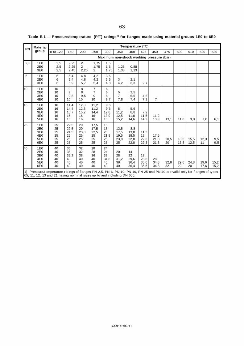
63
Table E.1 — Pressure/temperature (P/T) ratings 1) for flanges made using material groups 1E0 to 6E0
PN Materialgroup
Temperature (°C)
0 to 120 150 200 250 300 350 400 425 450 475 500 510 520 530
Maximum non-shock working pressure (bar)
2,5 1E02E03E0
2,52,52,5
2,252,252,45
222,25
1,751,752
1,51,51,75
1,251,38
0,881,13
6 1E02E03E0
666
5,45,45,9
4,84,85,7
4,24,25,4
3,63,64,8
34,2
2,13,3 2,7
10 1E02E03E04E0
10101010
999,8
10
889,5
10
779
10
6688,7
577,8
3,55,57,4
4,57,2 7
16 1E02E03E04E05E0
1616161616
14,414,415,71616
12,812,815,21616
11,211,214,41616
9,69,6
12,813,916
811,212,515,2
5,68,8
11,814,6
7,211,514,2
11,213,9 13,1 11,8 9,9 7,8 6,1
25 1E02E03E04E05E06E0
252525252525
22,522,524,5252525
202023,8252525
17,517,522,5252525
15152021,82525
12,517,519,523,825
8,813,818,522,822,8
11,31822,322,3
17,521,821,8
20,520
18,513,8
15,512,5
12,311
9,59,5
40 1E02E03E04E05E06E0
404040404040
363639,2404040
323238404040
282836404040
24243234,84040
202831,23840
142229,636,436,4
1828,835,635,6
2834,834,8
32,832
29,622
24,820
19,617,6
15,215,2
1) Pressure/temperature ratings of flanges PN 2,5, PN 6, PN 10, PN 16, PN 25 and PN 40 are valid only for flanges of types05, 11, 12, 13 and 21 having nominal sizes up to and including DN 600.
COPYRIGHT
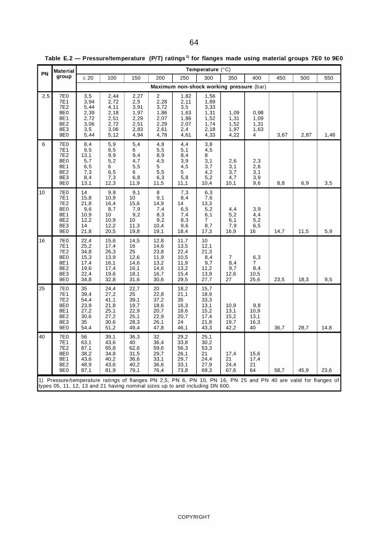
64
Table E.2 — Pressure/temperature (P/T) ratings 1) for flanges made using material groups 7E0 to 9E0
PN Materialgroup
Temperature (°C)
≤ 20 100 150 200 250 300 350 400 450 500 550
Maximum non-shock working pressure (bar)
2,5 7E07E17E28E08E18E28E39E0
3,53,945,442,392,723,063,55,44
2,442,724,112,182,512,723,065,12
2,272,53,911,972,292,512,834,94
22,283,721,862,072,292,614,78
1,822,113,51,631,862,072,44,61
1,561,893,331,311,521,742,184,33
1,091,311,521,974,22
0,981,091,311,634 3,67 2,87 1,48
6 7E07E17E28E08E18E28E39E0
8,49,5
13,15,76,57,38,4
13,1
5,96,59,95,266,57,3
12,3
5,469,44,75,566,8
11,9
4,85,58,94,555,56,3
11,5
4,45,18,43,94,555,8
11,1
3,84,583,13,74,25,2
10,4
2,63,13,74,7
10,1
2,32,63,13,99,6 8,8 6,9 3,5
10 7E07E17E28E08E18E28E39E0
1415,821,89,6
10,912,21421,8
9,810,916,48,7
1010,912,220,5
9,11015,6
7,99,2
1011,319,8
89,1
14,97,48,39,2
10,419,1
7,38,4
146,57,48,39,6
18,4
6,37,6
13,35,26,178,7
17,3
4,45,26,17,9
16,9
3,94,45,26,5
16 14,7 11,5 5,9
16 7E07E17E28E08E18E28E39E0
22,425,234,815,317,419,622,434,8
15,617,426,313,916,117,419,632,8
14,5162512,614,616,118,131,6
12,814,623,811,913,214,616,730,6
11,713,522,410,511,913,215,429,5
1012,121,3
8,49,7
11,213,927,7
78,49,7
12,627
6,378,4
10,525,6 23,5 18,3 9,5
25 7E07E17E28E08E18E28E39E0
3539,454,423,927,230,63554,4
24,427,241,121,825,127,230,651,2
22,72539,119,722,925,128,349,4
2022,837,218,620,722,926,147,8
18,221,13516,318,620,72446,1
15,718,933,313,115,217,421,843,3
10,913,115,219,742,2
9,810,913,116,340 36,7 28,7 14,8
40 7E07E17E28E08E18E29E0
5663,187,138,243,648,987,1
39,143,665,834,840,243,681,9
36,34062,631,536,640,279,1
3236,459,629,733,136,676,4
29,233,856,326,129,733,173,8
25,130,253,32124,427,969,3
17,42124,467,6
15,617,42164 58,7 45,9 23,6
1) Pressure/temperature ratings of flanges PN 2,5, PN 6, PN 10, PN 16, PN 25 and PN 40 are valid for flanges oftypes 05, 11, 12, 13 and 21 having nominal sizes up to and including DN 600.
COPYRIGHT
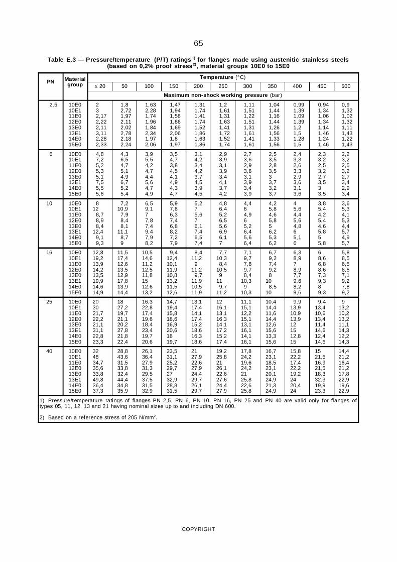
65
Table E.3 — Pressure/temperature (P/T) ratings 1) for flanges made using austenitic stainless steels(based on 0,2% proof stress2), material groups 10E0 to 15E0
PN Materialgroup
Temperature (°C)
≤ 20 50 100 150 200 250 300 350 400 450 500
Maximum non-shock working pressure (bar)
2,5 10E010E111E012E013E013E114E015E0
232,172,222,113,112,282,33
1,82,721,972,112,022,782,182,24
1,632,281,741,961,842,341,972,06
1,471,941,581,861,692,061,81,97
1,311,741,411,741,521,861,631,86
1,21,611,311,631,411,721,521,74
1,111,511,221,511,311,611,411,61
1,041,441,161,441,261,561,331,56
0,991,391,091,391,21,51,281,5
0,941,341,061,341,141,461,241,46
0,91,321,021,321,111,431,221,43
6 10E010E111E012E013E013E114E015E0
4,87,25,25,35,17,55,55,6
4,36,54,75,14,96,75,25,4
3,95,54,24,74,45,64,74,9
3,54,73,84,54,14,94,34,7
3,14,23,44,23,74,53,94,5
2,93,93,13,93,44,13,74,2
2,73,62,93,63,13,93,43,9
2,53,52,83,533,73,23,7
2,43,32,63,32,93,63,13,6
2,33,22,53,22,73,533,5
2,23,22,53,22,73,42,93,4
10 10E010E111E012E013E013E114E015E0
812
8,78,98,4
12,49,19,3
7,210,9
7,98,48,1
11,18,79
6,59,177,87,49,47,98,2
5,97,86,37,46,88,27,27,9
5,275,676,17,46,57,4
4,86,45,26,55,66,96,17
4,464,965,26,45,66,4
4,25,84,65,856,25,36,2
45,64,45,64,865,16
3,85,44,25,44,65,855,8
3,65,34,15,34,45,74,95,7
16 10E010E111E012E013E013E114E015E0
12,819,213,914,213,519,914,614,9
11,517,412,613,512,917,813,914,4
10,514,611,212,511,81512,613,2
9,412,410,111,910,813,211,512,6
8,411,2
911,2
9,711,910,511,9
7,710,38,4
10,59
119,7
11,2
7,19,77,89,78,4
10,39
10,3
6,79,27,49,28
108,5
10
6,38,978,97,79,68,29,6
68,66,88,67,39,389,3
5,88,56,58,57,19,27,89,2
25 10E010E111E012E013E013E114E015E0
203021,722,221,131,122,823,3
1827,219,721,120,227,821,822,4
16,322,817,419,618,423,419,720,6
14,719,415,818,616,920,61819,7
13,117,414,117,415,218,616,318,6
1216,113,116,314,117,215,217,4
11,115,112,215,113,116,114,116,1
10,414,411,614,412,615,613,315,6
9,913,910,913,9121512,815
9,413,410,613,411,414,612,414,6
913,210,213,211,114,312,214,3
40 10E010E111E012E013E013E114E015E0
324834,735,633,849,836,437,3
28,843,631,533,832,444,434,835,9
26,136,427,931,329,537,531,532,9
23,531,125,229,72732,928,831,5
2127,922,627,924,429,726,129,7
19,225,82126,122,627,624,427,9
17,824,219,624,22125,822,625,8
16,723,118,523,120,124,921,324,9
15,822,217,422,219,22420,424
1521,516,921,518,332,319,923,3
14,421,216,421,217,822,919,622,9
1) Pressure/temperature ratings of flanges PN 2,5, PN 6, PN 10, PN 16, PN 25 and PN 40 are valid only for flanges oftypes 05, 11, 12, 13 and 21 having nominal sizes up to and including DN 600.
2) Based on a reference stress of 205 N/mm2.
COPYRIGHT
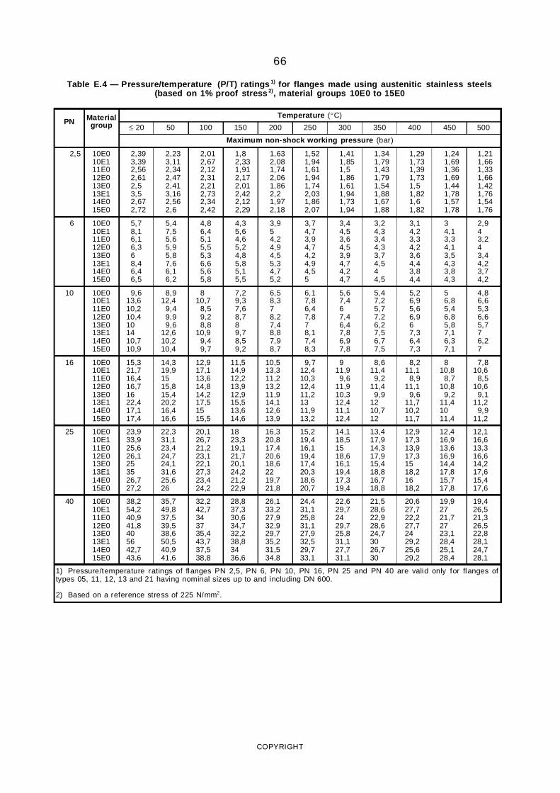
66
Table E.4 — Pressure/temperature (P/T) ratings 1) for flanges made using austenitic stainless steels(based on 1% proof stress 2), material groups 10E0 to 15E0
PN Materialgroup
Temperature (°C)
≤ 20 50 100 150 200 250 300 350 400 450 500
Maximum non-shock working pressure (bar)
2,5 10E010E111E012E013E013E114E015E0
2,393,392,562,612,53,52,672,72
2,233,112,342,472,413,162,562,6
2,012,672,122,312,212,732,342,42
1,82,331,912,172,012,422,122,29
1,632,081,742,061,862,21,972,18
1,521,941,611,941,742,031,862,07
1,411,851,51,861,611,941,731,94
1,341,791,431,791,541,881,671,88
1,291,731,391,731,51,821,61,82
1,241,691,361,691,441,781,571,78
1,211,661,331,661,421,761,541,76
6 10E010E111E012E013E013E114E015E0
5,78,16,16,368,46,46,5
5,47,55,65,95,87,66,16,2
4,86,45,15,55,36,65,65,8
4,35,64,65,24,85,85,15,5
3,954,24,94,55,34,75,2
3,74,73,94,74,24,94,55
3,44,53,64,53,94,74,24,7
3,24,33,44,33,74,544,5
3,14,23,34,23,64,43,84,4
34,13,34,13,54,33,84,3
2,943,243,44,23,74,2
10 10E010E111E012E013E013E114E015E0
9,613,610,210,4101410,710,9
8,912,4
9,49,99,6
12,610,210,4
810,7
8,59,28,8
10,99,49,7
7,29,37,68,789,78,59,2
6,58,378,27,48,87,98,7
6,17,86,47,878,17,48,3
5,67,467,46,47,86,97,8
5,47,25,77,26,27,56,77,5
5,26,95,66,967,36,47,3
56,85,46,85,87,16,37,1
4,86,65,36,65,776,27
16 10E010E111E012E013E013E114E015E0
15,321,716,416,71622,417,117,4
14,319,91515,815,420,216,416,6
12,917,113,614,814,217,51515,5
11,514,912,213,912,915,513,614,6
10,513,311,213,211,914,112,613,9
9,712,410,312,411,21311,913,2
911,99,6
11,910,312,411,112,4
8,611,49,2
11,49,9
1210,712
8,211,1
8,911,1
9,611,710,211,7
810,8
8,710,8
9,211,41011,4
7,810,6
8,510,6
9,111,2
9,911,2
25 10E010E111E012E013E013E114E015E0
23,933,925,626,1253526,727,2
22,331,123,424,724,131,625,626
20,126,721,223,122,127,323,424,2
1823,319,121,720,124,221,222,9
16,320,817,420,618,62219,721,8
15,219,416,119,417,420,318,620,7
14,118,51518,616,119,417,319,4
13,417,914,317,915,418,816,718,8
12,917,313,917,31518,21618,2
12,416,913,616,914,417,815,717,8
12,116,613,316,614,217,615,417,6
40 10E010E111E012E013E013E114E015E0
38,254,240,941,8405642,743,6
35,749,837,539,538,650,540,941,6
32,242,7343735,443,737,538,8
28,837,330,634,732,238,83436,6
26,133,227,932,929,735,231,534,8
24,431,125,831,127,932,529,733,1
22,629,72429,725,831,127,731,1
21,528,622,928,624,73026,730
20,627,722,227,72429,225,629,2
19,92721,72723,128,425,128,4
19,426,521,326,522,828,124,728,1
1) Pressure/temperature ratings of flanges PN 2,5, PN 6, PN 10, PN 16, PN 25 and PN 40 are valid only for flanges oftypes 05, 11, 12, 13 and 21 having nominal sizes up to and including DN 600.
2) Based on a reference stress of 225 N/mm2.
COPYRIGHT
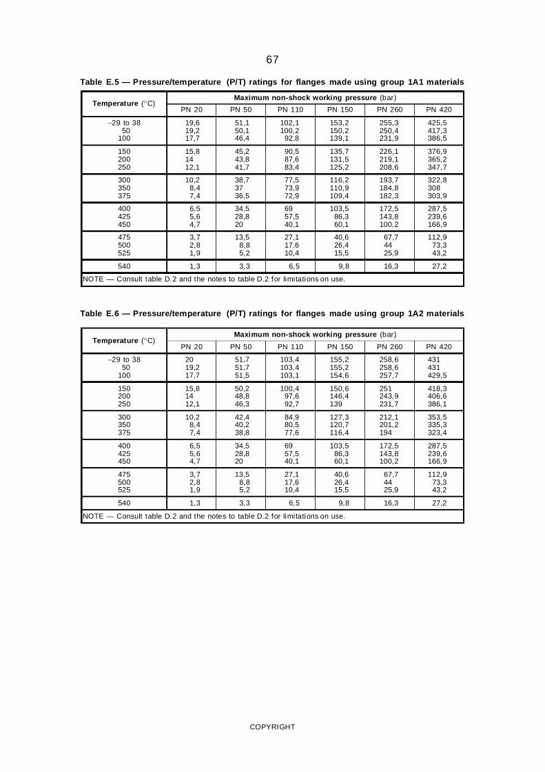
67
Table E.5 — Pressure/temperature (P/T) ratings for flanges made using group 1A1 materials
Temperature (°C)Maximum non-shock working pressure (bar)
PN 20 PN 50 PN 110 PN 150 PN 260 PN 420
−29 to 3850
100
19,619,217,7
51,150,146,4
102,1100,2
92,8
153,2150,2139,1
255,3250,4231,9
425,5417,3386,5
150200250
15,81412,1
45,243,841,7
90,587,683,4
135,7131,5125,2
226,1219,1208,6
376,9365,2347,7
300350375
10,28,47,4
38,73736,5
77,573,972,9
116,2110,9109,4
193,7184,8182,3
322,8308303,9
400425450
6,55,64,7
34,528,820
6957,540,1
103,586,360,1
172,5143,8100,2
287,5239,6166,9
475500525
3,72,81,9
13,58,85,2
27,117,610,4
40,626,415,5
67,74425,9
112,973,343,2
540 1,3 3,3 6,5 9,8 16,3 27,2
NOTE — Consult table D.2 and the notes to table D.2 for limitations on use.
Table E.6 — Pressure/temperature (P/T) ratings for flanges made using group 1A2 materials
Temperature (°C)Maximum non-shock working pressure (bar)
PN 20 PN 50 PN 110 PN 150 PN 260 PN 420
−29 to 3850
100
2019,217,7
51,751,751,5
103,4103,4103,1
155,2155,2154,6
258,6258,6257,7
431431429,5
150200250
15,81412,1
50,248,846,3
100,497,692,7
150,6146,4139
251243,9231,7
418,3406,6386,1
300350375
10,28,47,4
42,440,238,8
84,980,577,6
127,3120,7116,4
212,1201,2194
353,5335,3323,4
400425450
6,55,64,7
34,528,820
6957,540,1
103,586,360,1
172,5143,8100,2
287,5239,6166,9
475500525
3,72,81,9
13,58,85,2
27,117,610,4
40,626,415,5
67,74425,9
112,973,343,2
540 1,3 3,3 6,5 9,8 16,3 27,2
NOTE — Consult table D.2 and the notes to table D.2 for limitations on use.
COPYRIGHT
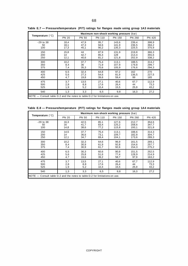
68
Table E.7 — Pressure/temperature (P/T) ratings for flanges made using group 1A3 materials
Temperature (°C)Maximum non-shock working pressure (bar)
PN 20 PN 50 PN 110 PN 150 PN 260 PN 420
−29 to 3850
100
18,418,117,3
47,947,345,1
95,794,690,2
143,6141,9135,3
239,4236,5225,5
398,9394,2375,9
150200250
15,81412,1
4442,740,6
87,985,481,2
131,9128121,8
219,8213,4202,9
366,3355,6338,2
300350375
10,28,47,4
37,73635,3
75,471,970,6
113,1107,9105,9
188,5179,8176,6
314,2299,7294,3
400425450
6,55,64,7
32,427,319,8
64,854,639,6
97,281,959,4
162136,5
99
270227,5165
475500525
3,72,81,9
13,58,85,2
27,117,610,4
40,626,415,5
67,74425,9
112,973,343,2
540 1,3 3,3 6,5 9,8 16,3 27,2
NOTE — Consult table D.2 and the notes to table D.2 for limitations on use.
Table E.8 — Pressure/temperature (P/T) ratings for flanges made using group 1A4 materials
Temperature (°C)Maximum non-shock working pressure (bar)
PN 20 PN 50 PN 110 PN 150 PN 260 PN 420
−29 to 3850
100
16,31614,8
42,541,738,6
85,183,477,2
127,6125,2115,8
212,7208,6193,1
354,6347,7321,8
150200250
14,51412,1
37,736,634,7
75,473,169,4
113,1109,7104,1
188,6182,8173,6
314,3304,7289,3
300350375
10,28,47,4
32,330,930,9
64,661,961,7
96,992,892,6
161,5154,6154,3
269,1257,7275,2
400425450
6,55,64,7
30,325,819,6
60,651,639,2
90,977,458,7
151,5128,9
97,9
252,5214,9163,2
475500525
3,72,81,9
13,58,85,2
27,117,610,4
40,626,415,5
67,74425,9
112,973,343,2
540 1,3 3,3 6,5 9,8 16,3 27,2
NOTE — Consult table D.2 and the notes to table D.2 for limitations on use.
COPYRIGHT
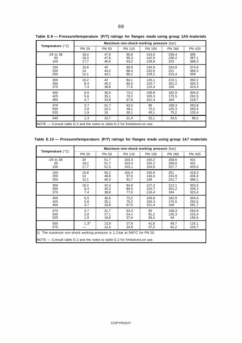
69
Table E.9 — Pressure/temperature (P/T) ratings for flanges made using group 1A5 materials
Temperature (°C)Maximum non-shock working pressure (bar)
PN 20 PN 50 PN 110 PN 150 PN 260 PN 420
−29 to 3850
100
18,418,317,7
47,947,646,6
95,895,393,2
143,6142,9139,8
239,4238,2233
399397,1388,3
150200250
15,81412,1
4544,243,1
89,988,486,2
134,9132,6129,2
224,8221215,4
374,6368,3359
300350375
10,28,47,4
4240,238,8
84,180,577,6
126,1120,7116,4
210,1201,2194
350,2335,3323,4
400425450
6,55,64,7
36,635,133,8
73,270,267,6
109,8105,3101,4
182,9175,5169
304,9292,5218,7
475500525
3,72,81,9
31,724,115
63,348,130,1
9572,245,1
158,3120,3
75,2
263,8200,6125,4
540 1,3 10,7 21,4 32,1 53,5 89,2
NOTE — Consult table D.2 and the notes to table D.2 for limitations on use.
Table E.10 — Pressure/temperature (P/T) ratings for flanges made using group 1A7 materials
Temperature (°C)Maximum non-shock working pressure (bar)
PN 20 PN 50 PN 110 PN 150 PN 260 PN 420
−29 to 3850
100
2019,217,7
51,751,751,5
103,4103,4103,1
155,2155,2154,6
258,6258,6257,7
431431429,5
150200250
15,81412,1
50,248,846,3
100,497,692,7
150,6146,4139
251243,9231,7
418,3406,6386,1
300350375
10,28,47,4
42,440,238,8
84,980,577,6
127,3120,7116,4
212,1201,2194
353,5335,3323,4
400425450
6,55,64,7
36,635,133,8
73,270,267,6
109,8105,3101,4
182,9175,5169
304,9292,5281,7
475500525
3,72,81,9
31,727,118,8
63,354,137,6
9581,256,4
158,3135,3
94
263,8225,4156,6
550575
1,31)
—13,912,4
27,924,9
41,837,3
69,762,2
116,1103,7
1) The maximum non-shock working pressure is 1,3 bar at 540°C for PN 20.
NOTE — Consult table D.2 and the notes to table D.2 for limitations on use.
COPYRIGHT
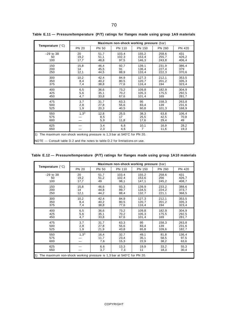
70
Table E.11 — Pressure/temperature (P/T) ratings for flanges made using group 1A9 materials
Temperature (°C)Maximum non-shock working pressure (bar)
PN 20 PN 50 PN 110 PN 150 PN 260 PN 420
−29 to 3850
100
2019,217,7
51,751,148,8
103,4102,3
97,5
155,2153,4146,3
258,6255,7243,8
431426,2406,4
150200250
15,81412,1
46,445,544,5
92,79188,9
139,1136,4133,4
231,9227,4222,3
386,4379370,6
300350375
10,28,47,4
42,440,238,8
84,980,577,6
127,3120,7116,4
212,1201,2194
353,5335,3323,4
400425450
6,55,64,7
36,635,133,8
73,270,267,6
109,8105,3101,4
182,9175,5169
304,9292,5281,7
475500525
3,72,81,9
31,727,820,3
63,355,640,5
9583,460,8
158,3139101,3
263,8231,6168,9
550575600
1,31)
——
12,88,55,9
25,51711,8
38,325,517,6
63,842,529,4
106,470,849
625650
——
3,42,3
6,84,6
10,17
16,911,6
28,219,3
1) The maximum non-shock working pressure is 1,3 bar at 540°C for PN 20.
NOTE — Consult table D.2 and the notes to table D.2 for limitations on use.
Table E.12 — Pressure/temperature (P/T) ratings for flanges made using group 1A10 materials
Temperature (°C)Maximum non-shock working pressure (bar)
PN 20 PN 50 PN 110 PN 150 PN 260 PN 420
−29 to 3850
100
2019,217,7
51,751,249
103,4102,4
98,1
155,2153,6147,1
258,6256245,2
431426,7408,7
150200250
15,81412,1
46,644,844,2
93,389,788,4
139,9134,5132,7
233,2224,2221,1
388,6373,7368,5
300350375
10,28,47,4
42,440,238,8
84,980,577,6
127,3120,7116,4
212,1201,2194
353,5335,3323,4
400425450
6,55,64,7
36,635,133,8
73,270,267,6
109,8105,3101,4
182,9175,5169
304,9292,5281,7
475500525
3,72,81,9
31,727,821,9
63,355,643,8
9583,465,8
158,3139109,6
263,8231,6182,7
550575600
1,31)
——
16,411,7
7,6
32,723,415,3
49,135,122,9
81,858,538,2
136,497,563,6
625650
——
6,63,7
13,37,3
19,911
33,218,3
55,330,4
1) The maximum non-shock working pressure is 1,3 bar at 540°C for PN 20.
COPYRIGHT
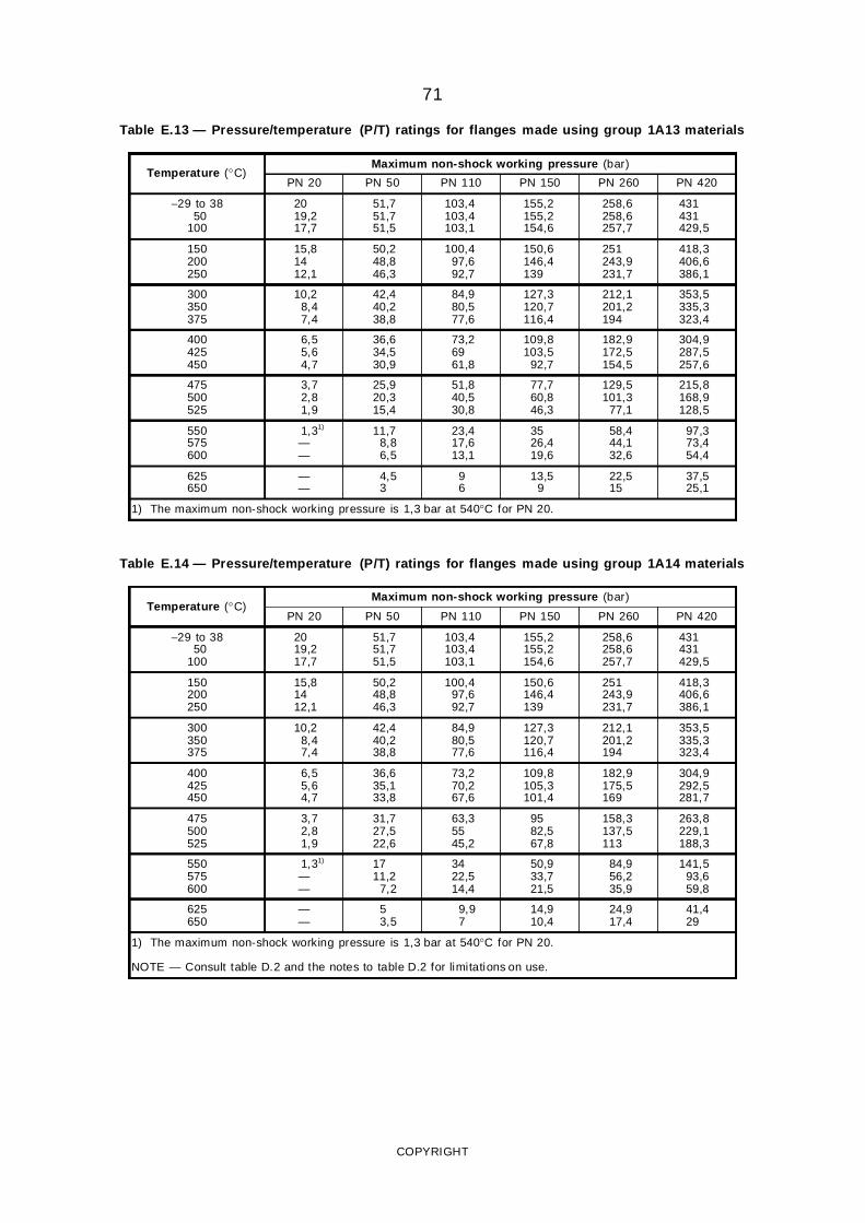
71
Table E.13 — Pressure/temperature (P/T) ratings for flanges made using group 1A13 materials
Temperature (°C)Maximum non-shock working pressure (bar)
PN 20 PN 50 PN 110 PN 150 PN 260 PN 420
−29 to 3850
100
2019,217,7
51,751,751,5
103,4103,4103,1
155,2155,2154,6
258,6258,6257,7
431431429,5
150200250
15,81412,1
50,248,846,3
100,497,692,7
150,6146,4139
251243,9231,7
418,3406,6386,1
300350375
10,28,47,4
42,440,238,8
84,980,577,6
127,3120,7116,4
212,1201,2194
353,5335,3323,4
400425450
6,55,64,7
36,634,530,9
73,26961,8
109,8103,5
92,7
182,9172,5154,5
304,9287,5257,6
475500525
3,72,81,9
25,920,315,4
51,840,530,8
77,760,846,3
129,5101,3
77,1
215,8168,9128,5
550575600
1,31)
——
11,78,86,5
23,417,613,1
3526,419,6
58,444,132,6
97,373,454,4
625650
——
4,53
96
13,59
22,515
37,525,1
1) The maximum non-shock working pressure is 1,3 bar at 540°C for PN 20.
Table E.14 — Pressure/temperature (P/T) ratings for flanges made using group 1A14 materials
Temperature (°C)Maximum non-shock working pressure (bar)
PN 20 PN 50 PN 110 PN 150 PN 260 PN 420
−29 to 3850
100
2019,217,7
51,751,751,5
103,4103,4103,1
155,2155,2154,6
258,6258,6257,7
431431429,5
150200250
15,81412,1
50,248,846,3
100,497,692,7
150,6146,4139
251243,9231,7
418,3406,6386,1
300350375
10,28,47,4
42,440,238,8
84,980,577,6
127,3120,7116,4
212,1201,2194
353,5335,3323,4
400425450
6,55,64,7
36,635,133,8
73,270,267,6
109,8105,3101,4
182,9175,5169
304,9292,5281,7
475500525
3,72,81,9
31,727,522,6
63,35545,2
9582,567,8
158,3137,5113
263,8229,1188,3
550575600
1,31)
——
1711,2
7,2
3422,514,4
50,933,721,5
84,956,235,9
141,593,659,8
625650
——
53,5
9,97
14,910,4
24,917,4
41,429
1) The maximum non-shock working pressure is 1,3 bar at 540°C for PN 20.
NOTE — Consult table D.2 and the notes to table D.2 for limitations on use.
COPYRIGHT
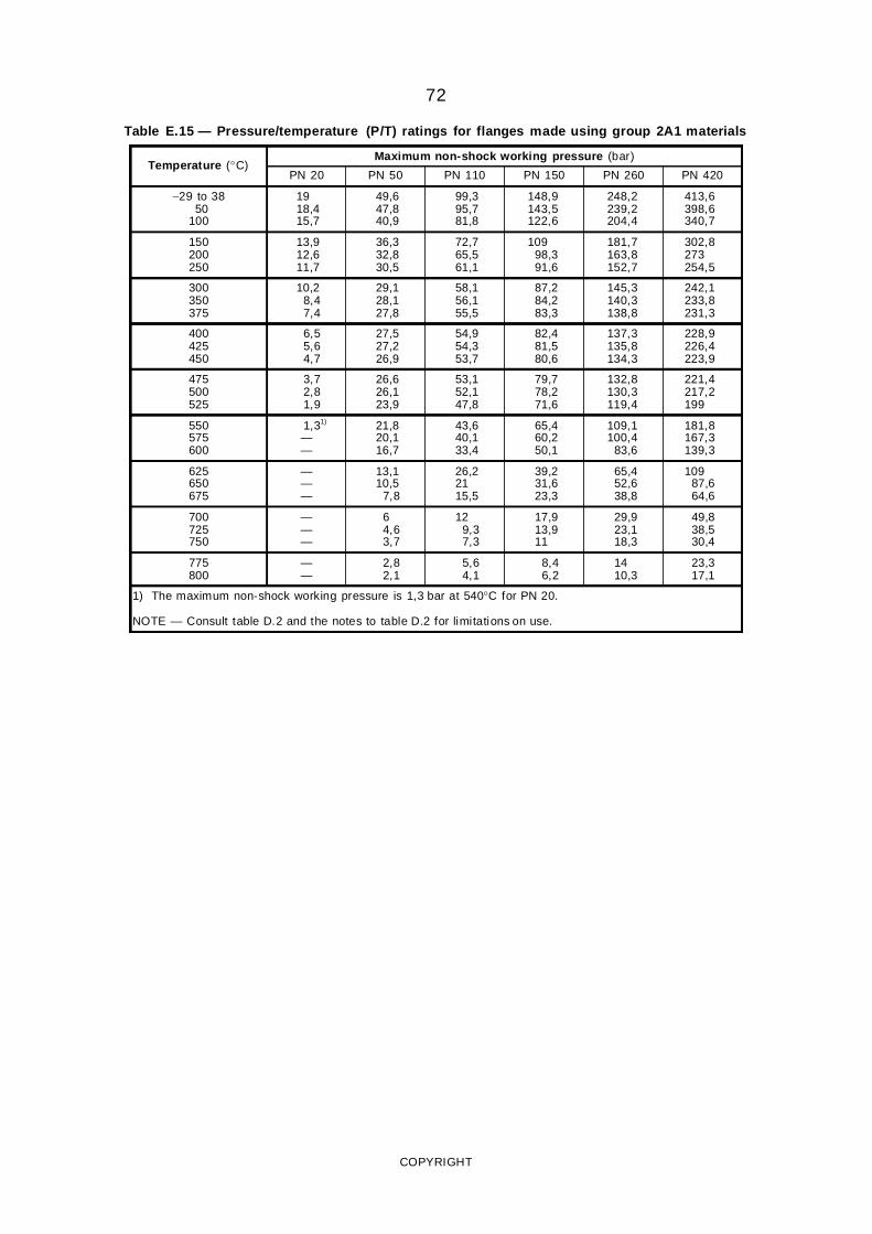
72
Table E.15 — Pressure/temperature (P/T) ratings for flanges made using group 2A1 materials
Temperature (°C)Maximum non-shock working pressure (bar)
PN 20 PN 50 PN 110 PN 150 PN 260 PN 420
−29 to 3850
100
1918,415,7
49,647,840,9
99,395,781,8
148,9143,5122,6
248,2239,2204,4
413,6398,6340,7
150200250
13,912,611,7
36,332,830,5
72,765,561,1
10998,391,6
181,7163,8152,7
302,8273254,5
300350375
10,28,47,4
29,128,127,8
58,156,155,5
87,284,283,3
145,3140,3138,8
242,1233,8231,3
400425450
6,55,64,7
27,527,226,9
54,954,353,7
82,481,580,6
137,3135,8134,3
228,9226,4223,9
475500525
3,72,81,9
26,626,123,9
53,152,147,8
79,778,271,6
132,8130,3119,4
221,4217,2199
550575600
1,31)
——
21,820,116,7
43,640,133,4
65,460,250,1
109,1100,4
83,6
181,8167,3139,3
625650675
———
13,110,5
7,8
26,22115,5
39,231,623,3
65,452,638,8
10987,664,6
700725750
———
64,63,7
129,37,3
17,913,911
29,923,118,3
49,838,530,4
775800
——
2,82,1
5,64,1
8,46,2
1410,3
23,317,1
1) The maximum non-shock working pressure is 1,3 bar at 540°C for PN 20.
NOTE — Consult table D.2 and the notes to table D.2 for limitations on use.
COPYRIGHT
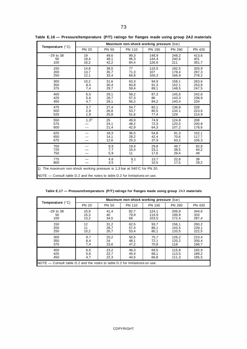
73
Table E.16 — Pressure/temperature (P/T) ratings for flanges made using group 2A2 materials
Temperature (°C)Maximum non-shock working pressure (bar)
PN 20 PN 50 PN 110 PN 150 PN 260 PN 420
−29 to 3850
100
1918,416,2
49,648,142,2
99,396,384,4
148,9144,4126,6
248,2240,6211
413,6401351,7
150200250
14,813,712,1
38,535,733,4
7771,366,8
115,5107100,2
192,5178,4166,9
320,9297,3278,2
300350375
10,28,47,4
31,630,429,7
63,360,859,4
94,991,389,1
158,1152,1148,5
263,6253,8247,5
400425450
6,55,64,7
29,128,728,1
58,257,356,2
87,38684,2
145,6143,3140,4
242,6238,9234
475500525
3,72,81,9
27,426,825,8
54,753,751,6
82,180,577,4
136,8134,1129
228223,6214,9
550575600
1,31)
——
2524,121,4
49,948,242,9
74,972,364,3
124,8120,5107,2
208200,8178,6
625650675
———
18,314,112,6
36,528,225,3
54,842,437,9
91,370,663,2
152,1117,7105,3
700725750
———
9,97,75,9
19,915,411
29,823,117,6
49,738,529,4
82,964,249
775800
——
4,63,5
9,17
13,710,5
22,817,5
3829,2
1) The maximum non-shock working pressure is 1,3 bar at 540°C for PN 20.
NOTE — Consult table D.2 and the notes to table D.2 for limitations on use.
Table E.17 — Pressure/temperature (P/T) ratings for flanges made using group 2A3 materials
Temperature (°C)Maximum non-shock working pressure (bar)
PN 20 PN 50 PN 110 PN 150 PN 260 PN 420
−29 to 3850
100
15,915,313,2
41,44034,5
82,779,969
124,1119,9103,5
206,8199,8172,4
344,6333287,4
150200250
121110,2
31,228,726,7
62,557,453,4
93,786,180,1
156,1143,5133,5
260,2239,1222,5
300350375
9,78,47,4
25,22423,6
50,548,147,2
75,772,170,8
126,2120,2118
210,4200,4196,7
400425450
6,55,64,7
23,222,722,3
46,345,444,5
69,568,166,8
115,8113,5111,3
192,9189,2185,5
NOTE — Consult table D.2 and the notes to table D.2 for limitations on use.
COPYRIGHT
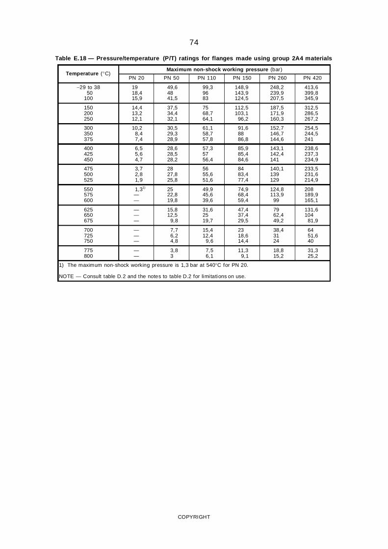
74
Table E.18 — Pressure/temperature (P/T) ratings for flanges made using group 2A4 materials
Temperature (°C)Maximum non-shock working pressure (bar)
PN 20 PN 50 PN 110 PN 150 PN 260 PN 420
−29 to 3850
100
1918,415,9
49,64841,5
99,39683
148,9143,9124,5
248,2239,9207,5
413,6399,8345,9
150200250
14,413,212,1
37,534,432,1
7568,764,1
112,5103,1
96,2
187,5171,9160,3
312,5286,5267,2
300350375
10,28,47,4
30,529,328,9
61,158,757,8
91,68886,8
152,7146,7144,6
254,5244,5241
400425450
6,55,64,7
28,628,528,2
57,35756,4
85,985,484,6
143,1142,4141
238,6237,3234,9
475500525
3,72,81,9
2827,825,8
5655,651,6
8483,477,4
140,1139129
233,5231,6214,9
550575600
1,31)
——
2522,819,8
49,945,639,6
74,968,459,4
124,8113,9
99
208189,9165,1
625650675
———
15,812,5
9,8
31,62519,7
47,437,429,5
7962,449,2
131,6104
81,9
700725750
———
7,76,24,8
15,412,4
9,6
2318,614,4
38,43124
6451,640
775800
——
3,83
7,56,1
11,39,1
18,815,2
31,325,2
1) The maximum non-shock working pressure is 1,3 bar at 540°C for PN 20.
NOTE — Consult table D.2 and the notes to table D.2 for limitations on use.
COPYRIGHT
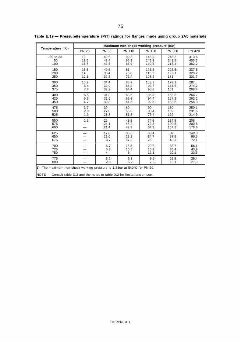
75
Table E.19 — Pressure/temperature (P/T) ratings for flanges made using group 2A5 materials
Temperature (°C)Maximum non-shock working pressure (bar)
PN 20 PN 50 PN 110 PN 150 PN 260 PN 420
−29 to 3850
100
1918,516,7
49,648,443,5
99,396,886,9
148,9145,1130,4
248,2241,9217,3
413,6403,2362,2
150200250
15,51412,1
40,538,436,2
8176,872,4
121,5115,3108,6
202,5192,1181
337,5320,2301,7
300350375
10,28,47,4
34,432,932,2
68,965,864,4
103,398,796,6
172,2164,5161
287274,2268,4
400425450
6,55,64,7
31,831,530,8
63,562,961,5
95,394,492,3
158,8157,3153,8
264,7262,2256,3
475500525
3,72,81,9
3027,825,8
6055,651,6
9083,477,4
150139129
250,1231,6214,9
550575600
1,31)
——
2524,121,4
49,948,242,9
74,972,364,3
124,8120,5107,2
208200,8178,6
625650675
———
17,811,6
8,7
35,623,217,3
53,434,726
8957,943,3
148,396,572,1
700725750
———
6,75,34
13,510,5
8
20,215,812,1
33,726,420,1
56,143,933,5
775800
——
3,22,6
6,35,2
9,57,5
15,813,1
26,421,9
1) The maximum non-shock working pressure is 1,3 bar at 540°C for PN 20.
NOTE — Consult table D.2 and the notes to table D.2 for limitations on use.
COPYRIGHT
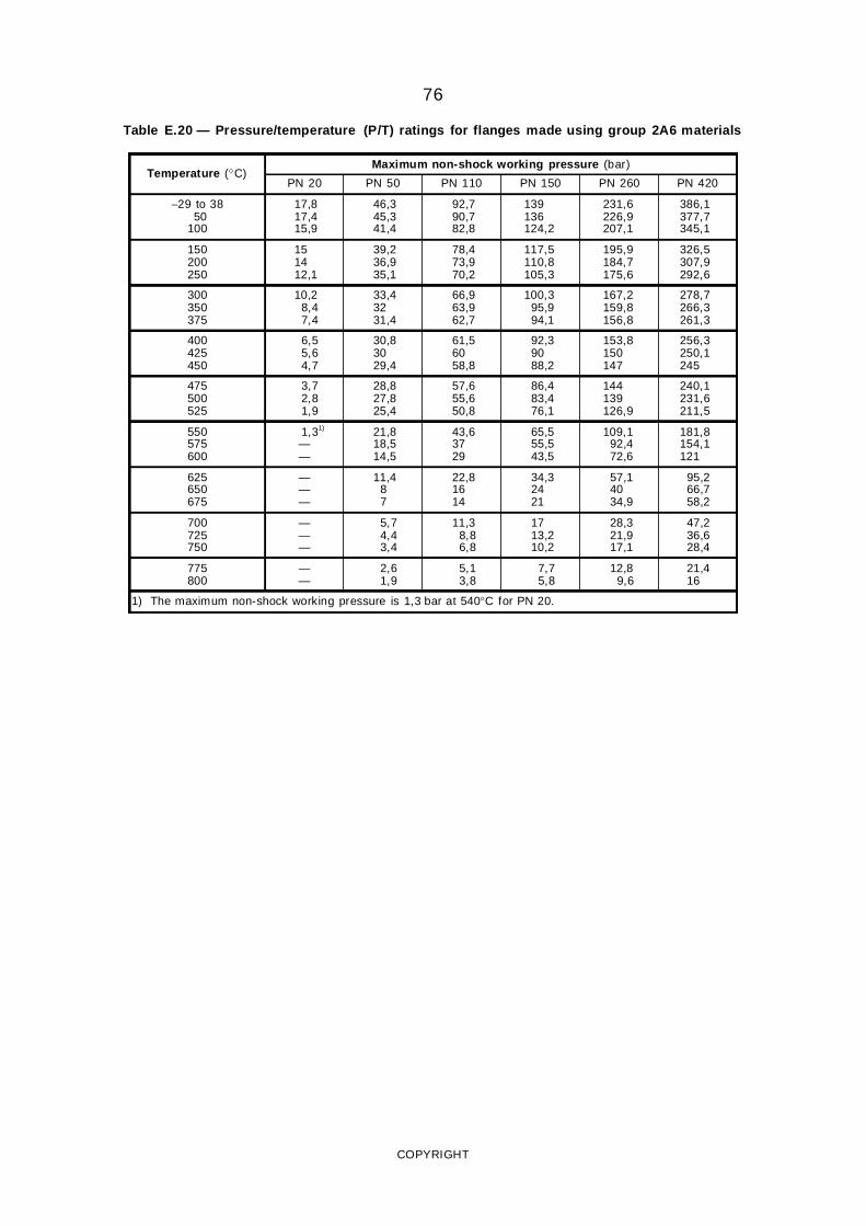
76
Table E.20 — Pressure/temperature (P/T) ratings for flanges made using group 2A6 materials
Temperature (°C)Maximum non-shock working pressure (bar)
PN 20 PN 50 PN 110 PN 150 PN 260 PN 420
−29 to 3850
100
17,817,415,9
46,345,341,4
92,790,782,8
139136124,2
231,6226,9207,1
386,1377,7345,1
150200250
151412,1
39,236,935,1
78,473,970,2
117,5110,8105,3
195,9184,7175,6
326,5307,9292,6
300350375
10,28,47,4
33,43231,4
66,963,962,7
100,395,994,1
167,2159,8156,8
278,7266,3261,3
400425450
6,55,64,7
30,83029,4
61,56058,8
92,39088,2
153,8150147
256,3250,1245
475500525
3,72,81,9
28,827,825,4
57,655,650,8
86,483,476,1
144139126,9
240,1231,6211,5
550575600
1,31)
——
21,818,514,5
43,63729
65,555,543,5
109,192,472,6
181,8154,1121
625650675
———
11,487
22,81614
34,32421
57,14034,9
95,266,758,2
700725750
———
5,74,43,4
11,38,86,8
1713,210,2
28,321,917,1
47,236,628,4
775800
——
2,61,9
5,13,8
7,75,8
12,89,6
21,416
1) The maximum non-shock working pressure is 1,3 bar at 540°C for PN 20.
COPYRIGHT
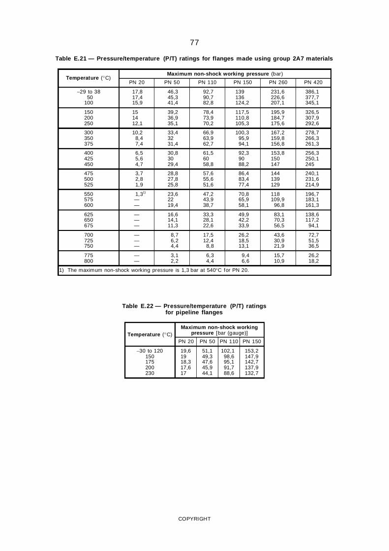
77
Table E.21 — Pressure/temperature (P/T) ratings for flanges made using group 2A7 materials
Temperature (°C)Maximum non-shock working pressure (bar)
PN 20 PN 50 PN 110 PN 150 PN 260 PN 420
−29 to 3850
100
17,817,415,9
46,345,341,4
92,790,782,8
139136124,2
231,6226,6207,1
386,1377,7345,1
150200250
151412,1
39,236,935,1
78,473,970,2
117,5110,8105,3
195,9184,7175,6
326,5307,9292,6
300350375
10,28,47,4
33,43231,4
66,963,962,7
100,395,994,1
167,2159,8156,8
278,7266,3261,3
400425450
6,55,64,7
30,83029,4
61,56058,8
92,39088,2
153,8150147
256,3250,1245
475500525
3,72,81,9
28,827,825,8
57,655,651,6
86,483,477,4
144139129
240,1231,6214,9
550575600
1,31)
——
23,62219,4
47,243,938,7
70,865,958,1
118109,9
96,8
196,7183,1161,3
625650675
———
16,614,111,3
33,328,122,6
49,942,233,9
83,170,356,5
138,6117,2
94,1
700725750
———
8,76,24,4
17,512,4
8,8
26,218,513,1
43,630,921,9
72,751,536,5
775800
——
3,12,2
6,34,4
9,46,6
15,710,9
26,218,2
1) The maximum non-shock working pressure is 1,3 bar at 540°C for PN 20.
Table E.22 — Pressure/temperature (P/T) ratingsfor pipeline flanges
Temperature (°C)Maximum non-shock working
pressure [bar (gauge)]
PN 20 PN 50 PN 110 PN 150
−30 to 120150175200230
19,61918,317,617
51,149,347,645,944,1
102,198,695,191,788,6
153,2147,9142,7137,9132,7
COPYRIGHT
78
Annex F(informative)
Design criteria (pipeline applications)
F.1 For PN 50, PN 110 and PN 150 flanges, the slopeand the outside diameter of the hub at the base aredesigned for welding ends having the same yieldstrength and thickness as those of the mating pipe. Thewall thickness of the intended mating pipe was basedon API 5LX-52 with a 0,68 design factor for the DN 650to DN 900 sizes, and API 5LX-65 with a 0,72 designfactor for the DN 950 to DN 1 500 sizes. When themanufacturer of the DN 650 to DN 900 sizes elects toutilize the alternative permitted in 2.4.5.1.2 or when themating pipe has a minimum specified yield strengthexceeding 448 N/mm2, it will be necessary torecalculate the design in accordance with therequirements of 2.4.5.1.2.
F.2 The design of the DN 950 and larger sizes of thePN 50 and higher class of welding neck flanges is
based on the flange material having a minimumspecified yield strength of at least 290 N/mm2 in a ringsection of the flange and a minimum yield strength atthe welding end at least equal to that specified for themating pipe. When the yield strength of the welding endof the flange is less than specified, compensation inaccordance with 2.4.5.1.2 may be made, but the hubslope and diameter at the larger end have to bepreserved.
F.3 The design of all sizes is based on the use ofheat-treated carbon steel bolt studs for PN 20 flangesand alloy steel bolt studs for PN 50, PN 110 andPN 150 flanges.
COPYRIGHT

79
Annex G(informative)
Bibliography
[1] ISO 468: 1982, Surface roughness — Parameters, their values and general rules for specifying requirements.
[2] ANSI/ASME B16.5: 1988, Pipe flanges and flanged fittings.
[3] ANSI/ASME B36.10M: 1985, Welded and seamless wrought steel pipe.
[4] API 5LX-52, Specification for high-test line pipe.
[5] API 5LX-65, Specification for high-test line pipe.
[6) MSS SP44, Steel pipe line flanges.
COPYRIGHT

This page has been left intentionally blank.
Related Documents