COMMUNICATIONS ALLIANCE LTD AUSTRALIAN STANDARD AS/CA S008:2010 Requirements for customer cabling products

Welcome message from author
This document is posted to help you gain knowledge. Please leave a comment to let me know what you think about it! Share it to your friends and learn new things together.
Transcript

COMMUNICATIONS ALLIANCE LTD
AUSTRALIAN STANDARD
AS/CA S008:2010
Requirements for customer cabling products
Australian Standard – Requirements for customer cabling products
This Standard was issued in draft form for public comment as DR AS/CA S008:2010
First Publication AS/ACIF S008:2001 Second edition AS/ACIF S008:2006 Third edition AS/CA S008:2010
ISBN: 1 74000 405 1
Communications Alliance Ltd (formerly Australian Communications Industry Forum Ltd) was formed in 2006 to provide a unified voice for the Australian communications industry and to lead it into the next generation of converging networks, technologies and services.
Disclaimers
1. Notwithstanding anything contained in this Standard:
(a) Communications Alliance disclaims responsibility (including where Communications Alliance or any of its officers, employees, agents or contractors has been negligent) for any direct or indirect loss, damage, claim, or liability any person may incur as a result of any:
(i) reliance on or compliance with this Standard;
(ii) inaccuracy or inappropriateness of this Standard; or
(iii) inconsistency of this Standard with any law; and
(b) Communications Alliance disclaims responsibility (including where Communications Alliance or any of its officers, employees, agents or contractors has been negligent) for ensuring compliance by any person with this Standard.
2. The above disclaimers will not apply to the extent they are inconsistent with any relevant legislation.
Copyright
© Communications Alliance Ltd 2010
This document is copyright and must not be used except as permitted below or under the Copyright Act 1968. You may reproduce and publish this document in whole or in part for your or your organisation’s own personal or internal compliance, educational or non-commercial purposes. You must not alter or amend this document in any way. You must not reproduce or publish this document for commercial gain without the prior written consent of Communications Alliance. Organisations wishing to reproduce or publish this document for commercial gain (i.e. for distribution to subscribers to an information service) may apply to subscribe to the Communications Alliance Publications Subscription Service by contacting the Communications Alliance Commercial Manager at [email protected]. If you publish any part of this document for any purpose, you must also publish this copyright notice as part of that publication.

- i -
AS/CA S008:2010 COPYRIGHT OCTOBER 2010
FOREWORD
General
This Standard was prepared by the CECRP/WC18 Cabling Standards Working Committee and most recently revised by the WC24 : Customer Cabling Products Revision Working Committee. It is one of a series of Telecommunication Standards developed under the Memorandum of Understanding between the Australian Communications Authority (ACA) and the Australian Communications Industry Forum (ACIF).
Note: On 1 July 2005 the ACA became the Australian Communications and Media Authority (ACMA) and the Memorandum of Understanding continues in effect as if the reference to the ACA were a reference to ACMA.
Communications Alliance was formed in 2006 and continues the functions previously fulfilled by ACIF.
This Standard is a revision of AS/ACIF S008:2006 Requirements for customer cabling products.
This Standard is the result of a consensus among representatives on the Communications Alliance Working Committee to produce it as an Australian Standard.
The requirements in this Standard are intended to be consistent with the aims of s376 of the Telecommunications Act 1997. Specifically these aims are—
(a) protecting the integrity of a telecommunications network or facility;
(b) protecting the health and safety of persons;
(c) ensuring access to emergency services; and
(d) ensuring interoperability with a standard telephone service.
It should be noted that some Customer Equipment (CE) may also need to comply with requirements in other Standards.
Applicable electrical safety Standards, EMC and EMR Standards may apply under Commonwealth or State/Territory laws, or both.
Intellectual property rights
Equipment, which is manufactured to comply with this Standard may require the use of technology which is protected by patent rights in Australia. Questions about the availability of such technology, under licence or otherwise, should be directed to the patent holder or Australian licensee (if known) or through inquiry at IP Australia which incorporates the Patent, Trade Marks and Designs Offices. Further information can be found at www.ipaustralia.gov.au.
- ii -
AS/CA S008:2010 COPYRIGHT OCTOBER 2010
Standards revision
Australian Standards (AS/ACIF and AS/CA Standards) developed by the Communications Alliance are updated according to the needs of the industry, by amendments or revision. Users of these Standards should make sure that they possess the latest amendments or editions. Representations concerning the need for a change to this AS/CA Standard should be addressed to—
The Project Manager Customer Equipment and Cable Reference Panel Communications Alliance PO Box 444 Milsons Point NSW 1565
Regulatory notice
This document will be submitted to the ACMA, for making as a technical standard under s376 of the Telecommunications Act 1997. Until it is made by the ACMA compliance with this Standard is voluntary.
The Standard as made by the ACMA will commence on the day after it registered under the Legislative Instruments Act 2003 (LIA) and it will be a disallowable instrument within the meaning of s46A of the Acts Interpretation Act 1901.
The ACMA is a Commonwealth authority with statutory powers to impose requirements concerning telecommunications Customer Equipment and Customer Cabling.
The ACMA requires Australian manufacturers and importers, or their Australian agents, of specified items of Customer Equipment and Customer Cabling to establish compliance with Standards such as this. Items are required to be labelled in accordance with the applicable labelling notices.
Details on current compliance arrangements can be obtained from the ACMA website at http://www.acma.gov.au or by contacting the ACMA below at:
Australian Communications and Media Authority PO Box 13112 Law Courts PO Melbourne VIC 8010 Australia
Telephone: +61 3 9963 6800 Facsimile: +61 3 9963 6899 TTY: +61 3 9963 6948
- iii -
AS/CA S008:2010 COPYRIGHT OCTOBER 2010
Introduction This introduction for the AS/ACIF S008:2010 Requirements for customer cabling products Standard is not an authoritative section of this Standard and is only provided as guidance for the user of the Standard to outline its objectives, the factors that have been taken into account in its development and to list the principle differences between the new and the previous edition.
The reader is directed to the clauses of this Standard for the specific requirements and to the Australian Communications and Media Authority (ACMA) for the applicable telecommunications labelling and compliance arrangements.
Note: Further information on the telecommunications labelling and compliance arrangements can be found in The Telecommunications Labelling (Customer Equipment and Customer Cabling) Notice (the TLN). The TLN can be obtained from the Australian Communications and Media Authority (ACMA) website at www.acma.gov.au.
The objective of this Standard is to provide the requirements for cabling products and related customer equipment for safety and interoperability in order to meet the regulatory arrangements in Australia.
The objective of this revision is to update the requirements of customer cabling products to reflect product supply in Australia and to update referenced Standards that have been revised since the previous edition of this Standard.
The requirements for surge suppression devices have been removed from this edition of the Standard as they are specified in AS/NZS 4117 Surge Protection Devices for Telecommunication Applications as referenced under the ACMA Telecommunications Labelling (Customer Equipment and Customer Cabling) Notice 2001.
The principle differences between this edition of AS/ACIF S008 and the previous edition are—
(i) the references to other Standards have been updated.
(ii) the requirements for insulating (Clause 5.4.1.4.1) and accessing (Clause 5.4.1.4.3) earthing/bonding bars and terminals have been amended.
(iii) the requirements for accessing earthing/bonding bars and terminals have been amended (Clause 5.4.1.4.3).
(iv) the requirements for surge suppression devices (SSDs) have been removed (the former Clause 5.4.1.5 in the 2006 edition).
(v) the requirements for PVC insulation and sheath (Tables 1 and 2) have been updated to align with values in the 2008 edition of AS 1049.
(vi) coax cables with a copper-clad aluminium centre conductor greater than 2 mm have been excluded from the conductor composition requirements of Clause 5.6.6.1.
(vii) the requirements for special applications cables (Clause 5.6.18) have been amended to include the requirements for insulation, sheath and jacket material in AS 1049.
- iv -
AS/CA S008:2010 COPYRIGHT OCTOBER 2010
(viii) requirements for access to cable terminations has been added (Clause 5.7.1.6).
(ix) fixed telecommunications socket-outlets have been disallowed from mounting on faceplates containing low voltage socket outlets or switches (Clause 5.7.1.7).
- v -
AS/CA S008:2010 COPYRIGHT OCTOBER 2010
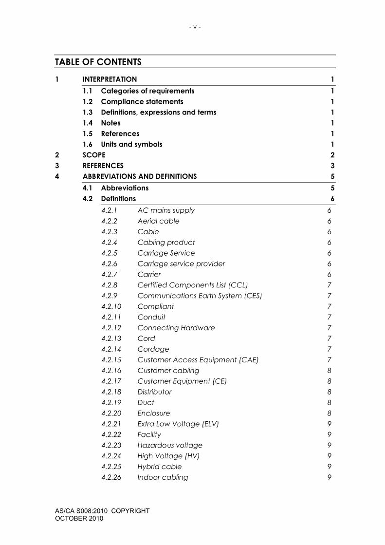
TABLE OF CONTENTS
1 INTERPRETATION 1 1.1 Categories of requirements 1 1.2 Compliance statements 1 1.3 Definitions, expressions and terms 1 1.4 Notes 1 1.5 References 1 1.6 Units and symbols 1
2 SCOPE 2 3 REFERENCES 3 4 ABBREVIATIONS AND DEFINITIONS 5
4.1 Abbreviations 5 4.2 Definitions 6
4.2.1 AC mains supply 6 4.2.2 Aerial cable 6 4.2.3 Cable 6 4.2.4 Cabling product 6 4.2.5 Carriage Service 6 4.2.6 Carriage service provider 6 4.2.7 Carrier 6 4.2.8 Certified Components List (CCL) 7 4.2.9 Communications Earth System (CES) 7 4.2.10 Compliant 7 4.2.11 Conduit 7 4.2.12 Connecting Hardware 7 4.2.13 Cord 7 4.2.14 Cordage 7 4.2.15 Customer Access Equipment (CAE) 7 4.2.16 Customer cabling 8 4.2.17 Customer Equipment (CE) 8 4.2.18 Distributor 8 4.2.19 Duct 8 4.2.20 Enclosure 8 4.2.21 Extra Low Voltage (ELV) 9 4.2.22 Facility 9 4.2.23 Hazardous voltage 9 4.2.24 High Voltage (HV) 9 4.2.25 Hybrid cable 9 4.2.26 Indoor cabling 9

- vi -
AS/CA S008:2010 COPYRIGHT OCTOBER 2010
4.2.27 Jumper 9 4.2.28 Lead-in cabling 9 4.2.29 Line 10 4.2.30 Low Voltage (LV) 10 4.2.31 Multidiscipline cable 10 4.2.32 Main Distribution Frame (MDF) 10 4.2.33 Network Termination Device (NTD) 10 4.2.34 Outdoor cable 10 4.2.35 Pigtail 10 4.2.36 Power feeding 11 4.2.37 SELV circuit 11 4.2.38 Special application cable 11 4.2.39 Telecommunications network 11 4.2.40 Telecommunications Network Voltage (TNV) circuit 11 4.2.41 Telephone cable 11 4.2.42 Trunking 11 4.2.43 Underground cable 12 4.2.44 Voltage classifications 12
5 REQUIREMENTS 14 5.1 General 14 5.2 Markings 14
5.2.1 Labelling Notice 14 5.2.2 Inappropriate markings 14 5.2.3 Additional markings (excluding cable markings) 14
5.3 Underground conduit 14 5.3.1 Colour 14 5.3.2 Underground conduit properties 15 5.3.3 Underground conduit markings 15
5.4 Cable distribution devices 15 5.4.1 Common requirements 15 5.4.2 Main distribution frame (MDF) 18
5.5 Optical fibre distribution devices and enclosures 19 5.6 Cables 19
5.6.1 General 19 5.6.2 Conductor and optical fibre identification 19 5.6.3 Insulation and sheath material 19 5.6.4 Flammability 20 5.6.5 UV resistance 20 5.6.6 Metallic conductors 21 5.6.7 Metallic shield 24

- vii -
AS/CA S008:2010 COPYRIGHT OCTOBER 2010
5.6.8 Water penetration test 25 5.6.9 Integral bearer or strengthener 25 5.6.10 Cable with specific attributes 26 5.6.11 Metallic paired cable 26 5.6.12 Cordage with metallic conductors 27 5.6.13 Cords with metallic conductors 27 5.6.14 Metallic jumper wire and jumper cable 28 5.6.15 Coaxial cable 28 5.6.16 Optical fibre cable 29 5.6.17 Blown fibre tube systems 30 5.6.18 Special application cables 30
5.7 Connecting hardware, including plugs and sockets of all designs 33 5.7.1 General 33 5.7.2 Eight (8) position modular plugs and sockets 34 5.7.3 Six (6) position modular plugs and sockets 34 5.7.4 600 series plugs and sockets 35
5.8 Cabling products for underground and aerial installations 35 5.8.1 Pits 35 5.8.2 Underground joint/termination enclosures 35 5.8.3 Underground and aerial cable terminations 36 5.8.4 Pillars and cabinets 36 5.8.5 Aerial joint/termination enclosures 36
6 PARTICIPANTS 45
APPENDICES
APPENDIX A 600 SERIES PLUGS AND SOCKETS 38 APPENDIX B CABLE COLOUR CODES 40
FIGURES
FIGURE A1 1 MATING DIMENSIONS FOR 600 SERIES PLUGS AND SOCKETS 39

- viii -
AS/CA S008:2010 COPYRIGHT OCTOBER 2010
TABLES
TABLE 1 PVC INSULATION REQUIREMENTS 20 TABLE 2 PVC SHEATH REQUIREMENTS 21 TABLE 3 CONDUCTOR RESISTANCE 22 TABLE 4 CABLE WITHSTAND VOLTAGES 22 TABLE 5 METALLIC CABLE PERFORMANCE PARAMETERS 24 TABLE 6 AUSTRALIAN STANDARDS APPLICABLE FOR CABLES USED IN SPECIAL
APPLICATIONS 32 TABLE B1 7 2-PAIR (QUAD) AND 3-PAIR TELEPHONE CABLE COLOUR CODE 40 TABLE B2 8 1-PAIR TO 5-PAIR CABLE COLOUR CODE 40 TABLE B3 9 COLOUR CODE FOR 5-PAIR TO 100-PAIR CABLES (20-PAIR UNITS) 41 TABLE B4 10 COLOUR CODE FOR 25-PAIR TO 100-PAIR CABLES (25-PAIR UNITS) 42 TABLE B5 11 COLOUR CODE FOR 5-PAIR TO 100-PAIR CABLES (10-PAIR UNITS) 43 TABLE B6 12 COLOUR CODE FOR 5-PAIR TO 200-PAIR CABLES (10-PAIR UNITS) 43 TABLE B7 13 OPTICAL FIBRE COLOUR CODE 44

- 1 -
AS/CA S008:2010 COPYRIGHT OCTOBER 2010
1 INTERPRETATION
1.1 Categories of requirements
This Standard contains mandatory requirements as well as provisions that are recommendations only. Mandatory requirements are designated by the words ‘shall’ or ‘shall not’. All other provisions are voluntary.
1.2 Compliance statements
Compliance statements, in italics, suggest methodologies for demonstrating Customer Cabling and related Customer Equipment compliance with the requirements.
1.3 Definitions, expressions and terms
If there is any conflict between the definitions used in this Standard and the definitions used in the Telecommunications Act 1997, the definitions in the Act take precedence.
1.4 Notes
Text denoted as ‘Note’ is for guidance in interpretation and is shown in smaller size type.
1.5 References
(a) Applicable editions (or versions) of other documents referred to in this Standard are specified in Section 3: REFERENCES.
(b) If a document refers to another document, the other document is a sub-referenced document.
(c) Where the edition (or version) of the sub-referenced document is uniquely identified in the reference document, then that edition (or version) applies.
(d) Where the edition (or version) of the sub-referenced document is not uniquely identified in the reference document, then the applicable edition (or version) is that which is current at the date the reference document is legislated under the applicable regulatory framework, or for a non- legislated document, the date upon which the document is published by the relevant standards organisation.
(e) A number in square brackets ‘[ ]’ refers to a document listed in Section 3: REFERENCES.
1.6 Units and symbols
In this Standard the International System (SI) of units and symbols is used in accordance with Australian Standard AS ISO 1000 [1].
- 2 -
AS/CA S008:2010 COPYRIGHT OCTOBER 2010
2 SCOPE 2.1 This Standard applies to cabling products (including cable and related
customer equipment) intended for connection to the customer side of the boundary of a telecommunications network.
2.2 This Standard does not apply to cabling products intended primarily for the distribution of AC mains supply.
2.3 This Standard does not apply to products intended to be used for telecommunications earthing systems or telecommunications power distribution (e.g. earthing/power conductors, earthing bars, busbars, earthing/power terminals, line tap devices, earth electrodes and associated fittings, batteries, fuses and circuit breakers).
2.4 This Standard does not apply to surge suppression devices.
Note: Requirements for surge suppression devices are specified in AS/NZS 4117 Surge Protection Devices for Telecommunication Applications. Refer to the ACMA Telecommunications Labelling (Customer Equipment and Customer Cabling) Notice 2001.
2.5 A cabling product is not excluded from the scope of this Standard by reason only that it forms part of equipment that is subject to another Standard, for example, distribution frames or cable tails that form part of Customer Access Equipment (CAE).
Note 1: The connection of cabling products includes connection otherwise than by means of physical contact, e.g. a connection by means of radiocommunication.
Note 2: This Standard should be read in conjunction with AS/ACIF S009 [20] which specifies the requirements for the installation and maintenance of fixed or concealed cabling or equipment that is connected or is intended to be connected to a telecommunications network.
- 3 -
AS/CA S008:2010 COPYRIGHT OCTOBER 2010
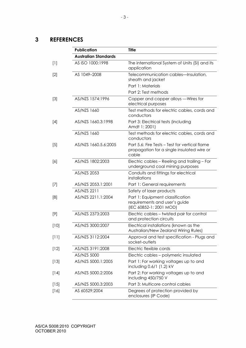
3 REFERENCES Publication Title Australian Standards [1] AS ISO 1000:1998 The international System of Units (SI) and its
application [2] AS 1049–2008 Telecommunication cables—Insulation,
sheath and jacket Part 1: Materials Part 2: Test methods
[3] AS/NZS 1574:1996 Copper and copper alloys —Wires for electrical purposes
AS/NZS 1660 Test methods for electric cables, cords and conductors
[4] AS/NZS 1660.3:1998 Part 3: Electrical tests (including Amdt 1: 2001)
AS/NZS 1660 Test methods for electric cables, cords and conductors
[5] AS/NZS 1660.5.6:2005 Part 5.6: Fire Tests – Test for vertical flame propagation for a single insulated wire or cable
[6] AS/NZS 1802:2003 Electric cables – Reeling and trailing – For underground coal mining purposes
AS/NZS 2053 Conduits and fittings for electrical installations
[7] AS/NZS 2053.1:2001 Part 1: General requirements AS/NZS 2211 Safety of laser products [8] AS/NZS 2211.1:2004 Part 1: Equipment classification
requirements and user’s guide (IEC 60852-1: 2001 MOD)
[9] AS/NZS 2373:2003 Electric cables – twisted pair for control and protection circuits
[10] AS/NZS 3000:2007 Electrical installations (known as the Australian/New Zealand Wiring Rules)
[11] AS/NZS 3112:2004 Approval and test specification - Plugs and socket-outlets
[12] AS/NZS 3191:2008 Electric flexible cords AS/NZS 5000 Electric cables – polymeric insulated [13] AS/NZS 5000.1:2005 Part 1: For working voltages up to and
including 0.6/1 (1.2) kV [14] AS/NZS 5000.2:2006 Part 2: For working voltages up to and
including 450/750 V [15] AS/NZS 5000.3:2003 Part 3: Multicore control cables [16] AS 60529:2004 Degrees of protection provided by
enclosures (IP Code)

- 4 -
AS/CA S008:2010 COPYRIGHT OCTOBER 2010
[17] AS/NZS 60695.2.13:2001 Fire hazard testing – glowing/hot wire based test methods – glow-wire ignitability test method for materials
[18] AS/NZS 60702.2:2005 Approval and test specification-Terminations and glands for mineral insulated metal-sheathed cables
AS/NZS 60950 Information Technology Equipment - Safety
[19] AS/NZS 60950.1:2003 Part 1: General requirements AS/ACIF Standards [20] AS/ACIF S009:2006 Installation requirements for customer
cabling – Wiring Rules IEC Publications [21] IEC 60096-1:1986 Radio-frequency cables. Part 1: General
requirements and measuring methods [22] IEC 60189-1:1986 Low-frequency cables and wires with PVC
insulation and PVC sheath. Part 1: General test and measuring methods
[23] IEC 60352-4:1994 Solderless non-accessible insulation displacement connections – General requirements, test methods and practical guidance
[24] IEC 60512-3-1 Edition 1.0 (2002-02)
Connectors for electronic equipment - Tests and measurements - Part 3-1: Insulation tests - Test 3a: Insulation resistance
[25] IEC 60603-7 Edition 3.0 (2008-07)
Connectors for electronic equipment – Part 7: Detail specification for 8-way, unshielded, free and fixed connectors
[26] IEC 60793-2 Edition 6.0 (2007-11)
Optical fibres. Part 2: Product specification - General
[27] IEC 60794-1-1:2001 Optical fibre cables - Part 1-1 – General [28] IEC 60794-1-2:2003 Optical fibre cables - Part 1-2 – Basic
optical cable test procedures. (for Water Penetration Test)
Other References [29] CFR FCC 47—
Part 68.500: October 2000
Code of Federal Regulations Federal Communications Commission Title 47: Telecommunications Part 68: Connection of terminal equipment to the telephone network Sub part F: Connector Specifications. Paragraph 500: Specifications

- 5 -
AS/CA S008:2010 COPYRIGHT OCTOBER 2010
4 ABBREVIATIONS AND DEFINITIONS For the purposes of this Standard, the following abbreviations and definitions apply.
4.1 Abbreviations
AC (or a.c.) alternating current (in r.m.s. value unless stated otherwise)
ACIF Australian Communications Industry Forum
ACMA Australian Communications and Media Authority AS Australian Standard CAE Customer Access Equipment CE Customer Equipment CES Communications Earth System DC (or d.c.) direct current ELV Extra-Low Voltage FCC Federal Communications Commission USA HV High Voltage IEC International Electrotechnical Commission IP International Protection (rating)
(sometimes referred to as Ingress Protection) IPXn rated for protection against ingress of water only
(n = 0 to 8, according to the degree of protection specified)
ISDN Integrated Services Digital Network LAN Local Area Network LV Low Voltage MDF Main Distribution Frame MIMS Mineral Insulated Metal Sheath NTD Network Termination Device NZS New Zealand Standard PVC Polyvinyl Chloride SELV Safety Extra-Low Voltage SWA Steel Wire Armouring TNV Telecommunications Network Voltage TO Telecommunications Outlet TRC Telecommunications Reference Conductor TS Technical Standard UV UltraViolet (radiation/light) Z0 Characteristic Impedance

- 6 -
AS/CA S008:2010 COPYRIGHT OCTOBER 2010
4.2 Definitions
4.2.1 AC mains supply
An AC power distribution system external to the equipment for supplying power to AC powered equipment
Note 1: Power sources may include public or private utilities and equivalent sources such as motor-driven generators and uninterruptible power supplies.
Note 2: Adapted from AS/NZS 60950.1 [19].
4.2.2 Aerial cable
Cable that is suspended between poles, buildings or other supporting structures external to a building.
4.2.3 Cable
An assembly of one or more cable units (e.g. pairs, quads, coaxial tubes, fibres) in an overall sheath.
Note: The assembly may include such things as a shield, moisture barrier, filling compound, strengthener or bearer wire.
4.2.4 Cabling product
A passive device (including any cable or connecting hardware) that is intended for use on the customer side of the boundary of a telecommunications network.
4.2.5 Carriage Service
A service for carrying communications by means of guided and/or unguided electromagnetic energy.
4.2.6 Carriage service provider
If a person supplies, or proposes to supply, a listed carriage service to the public using:
(a) a network unit owned by one or more carriers; or
(b) a network unit in relation to which a nominated carrier declaration is in force;
the person is a carriage service provider.
4.2.7 Carrier
The holder of a carrier licence.

- 7 -
AS/CA S008:2010 COPYRIGHT OCTOBER 2010
4.2.8 Certified Components List (CCL)
The list that was established by AUSTEL and is published by ACMA on its website.
Note 1: AUSTEL and the Spectrum Management Agency merged in the creation of the Australian Communications Authority (ACA) on 1 July 1997. The ACA and the Australian Broadcasting Authority (ABA) merged in the creation of the Australian Communications and Media Authority (ACMA) on 1 July 2005.
Note 2: The use of the CCL was discontinued on 1 July 1997, but remains in force in accordance with ACA TS 102–1998 Telecommunications Technical Standard (Customer Equipment and Customer Cabling).
4.2.9 Communications Earth System (CES)
A system of earthing using common elements to provide for earthing of electrical and communications equipment within a premises.
Note: A CES may be used for protective and functional earthing for telecommunications purposes.
4.2.10 Compliant
An item that has been labelled in accordance with the Telecommunications Labelling Notice.
4.2.11 Conduit
A tube or pipe that physically accommodates cables.
Note: In this Standard, conduit and pipe have the same meaning. See also ‘Duct’ and ‘Trunking’
4.2.12 Connecting Hardware
A passive device used to join or interconnect lines, or to connect customer equipment to a line.
4.2.13 Cord
A flexible cable with a minimum of one termination (e.g. on a plug).
Note: Cords are used for connection of moveable customer equipment or to afford flexibility, e.g. includes patch cords, fly leads and pigtails.
4.2.14 Cordage
A flexible cable that is not fitted with connectors, which may be used in the assembly of cords.
4.2.15 Customer Access Equipment (CAE)
Customer equipment with multiple ports (local or network) that provides access (gateway functions) to a telecommunications network and is capable of switching, storage, processing,
- 8 -
AS/CA S008:2010 COPYRIGHT OCTOBER 2010
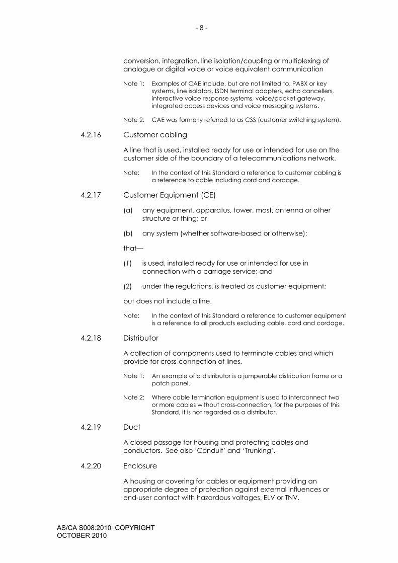
conversion, integration, line isolation/coupling or multiplexing of analogue or digital voice or voice equivalent communication
Note 1: Examples of CAE include, but are not limited to, PABX or key systems, line isolators, ISDN terminal adapters, echo cancellers, interactive voice response systems, voice/packet gateway, integrated access devices and voice messaging systems.
Note 2: CAE was formerly referred to as CSS (customer switching system).
4.2.16 Customer cabling
A line that is used, installed ready for use or intended for use on the customer side of the boundary of a telecommunications network.
Note: In the context of this Standard a reference to customer cabling is a reference to cable including cord and cordage.
4.2.17 Customer Equipment (CE)
(a) any equipment, apparatus, tower, mast, antenna or other structure or thing; or
(b) any system (whether software-based or otherwise);
that—
(1) is used, installed ready for use or intended for use in connection with a carriage service; and
(2) under the regulations, is treated as customer equipment;
but does not include a line.
Note: In the context of this Standard a reference to customer equipment is a reference to all products excluding cable, cord and cordage.
4.2.18 Distributor
A collection of components used to terminate cables and which provide for cross-connection of lines.
Note 1: An example of a distributor is a jumperable distribution frame or a patch panel.
Note 2: Where cable termination equipment is used to interconnect two or more cables without cross-connection, for the purposes of this Standard, it is not regarded as a distributor.
4.2.19 Duct
A closed passage for housing and protecting cables and conductors. See also ‘Conduit’ and ‘Trunking’.
4.2.20 Enclosure
A housing or covering for cables or equipment providing an appropriate degree of protection against external influences or end-user contact with hazardous voltages, ELV or TNV.
- 9 -
AS/CA S008:2010 COPYRIGHT OCTOBER 2010
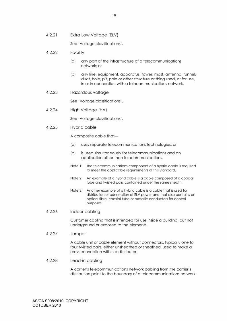
4.2.21 Extra Low Voltage (ELV)
See ‘Voltage classifications’.
4.2.22 Facility
(a) any part of the infrastructure of a telecommunications network; or
(b) any line, equipment, apparatus, tower, mast, antenna, tunnel, duct, hole, pit, pole or other structure or thing used, or for use, in or in connection with a telecommunications network.
4.2.23 Hazardous voltage
See ‘Voltage classifications’.
4.2.24 High Voltage (HV)
See ‘Voltage classifications’.
4.2.25 Hybrid cable
A composite cable that—
(a) uses separate telecommunications technologies; or
(b) is used simultaneously for telecommunications and an application other than telecommunications.
Note 1: The telecommunications component of a hybrid cable is required to meet the applicable requirements of this Standard.
Note 2: An example of a hybrid cable is a cable composed of a coaxial tube and twisted pairs contained under the same sheath.
Note 3: Another example of a hybrid cable is a cable that is used for distribution or connection of ELV power and that also contains an optical fibre, coaxial tube or metallic conductors for control purposes.
4.2.26 Indoor cabling
Customer cabling that is intended for use inside a building, but not underground or exposed to the elements.
4.2.27 Jumper
A cable unit or cable element without connectors, typically one to four twisted pairs, either unsheathed or sheathed, used to make a cross connection within a distributor.
4.2.28 Lead-in cabling
A carrier’s telecommunications network cabling from the carrier’s distribution point to the boundary of a telecommunications network.
- 10 -
AS/CA S008:2010 COPYRIGHT OCTOBER 2010
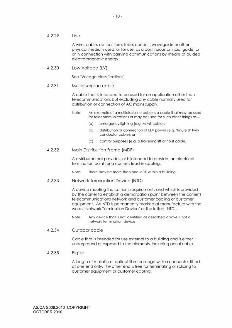
4.2.29 Line
A wire, cable, optical fibre, tube, conduit, waveguide or other physical medium used, or for use, as a continuous artificial guide for or in connection with carrying communications by means of guided electromagnetic energy.
4.2.30 Low Voltage (LV)
See ‘Voltage classifications’.
4.2.31 Multidiscipline cable
A cable that is intended to be used for an application other than telecommunications but excluding any cable normally used for distribution or connection of AC mains supply.
Note: An example of a multidiscipline cable is a cable that may be used for telecommunications or may be used for such other things as—
(a) emergency lighting (e.g. MIMS cable);
(b) distribution or connection of ELV power (e.g. ‘figure 8’ twin conductor cable); or
(c) control purposes (e.g. a travelling lift or hoist cable).
4.2.32 Main Distribution Frame (MDF)
A distributor that provides, or is intended to provide, an electrical termination point for a carrier’s lead-in cabling.
Note: There may be more than one MDF within a building.
4.2.33 Network Termination Device (NTD)
A device meeting the carrier’s requirements and which is provided by the carrier to establish a demarcation point between the carrier’s telecommunications network and customer cabling or customer equipment. An NTD is permanently marked at manufacture with the words ‘Network Termination Device’ or the letters ‘NTD’.
Note: Any device that is not identified as described above is not a network termination device.
4.2.34 Outdoor cable
Cable that is intended for use external to a building and is either underground or exposed to the elements, including aerial cable.
4.2.35 Pigtail
A length of metallic or optical fibre cordage with a connector fitted at one end only. The other end is free for terminating or splicing to customer equipment or customer cabling.
- 11 -
AS/CA S008:2010 COPYRIGHT OCTOBER 2010
4.2.36 Power feeding
The transfer of electrical power (usually DC) over a telecommunications line for telecommunications purposes to operate a powered device.
4.2.37 SELV circuit
See ‘Voltage classifications’.
4.2.38 Special application cable
A cable that—
(a) is intended to carry steady-state or change-of-state DC signals or AC signals less than 300 Hz between devices;
(b) is a cable intended to carry an industrial data signalling protocol, e.g. RS232 or RS485;
(c) is intended for multidiscipline use; or
(d) is a hybrid cable.
Note: A special application cable may include, but is not limited to—
(a) a cable used for connection of telecommunications power (usually SELV) and associated status and alarm circuits;
(b) a MIMS, EWIS or other fire detection or fire warning system cable;
(c) a security or control system cable; or
(d) a travelling lift or hoist cable.
4.2.39 Telecommunications network
A system, or series of systems that is operated by a carrier or carriage service provider and which carries, or is capable of carrying, communications by means of guided and/or unguided electromagnetic energy.
4.2.40 Telecommunications Network Voltage (TNV) circuit
See ‘Voltage classifications’
4.2.41 Telephone cable
A cable with metallic conductors (including cordage or a cord) designed to carry signals only in the 300 Hz to 100 kHz bandwidth.
4.2.42 Trunking
A tray or trough system with removable cover(s) along its length for housing and protecting cables.
Note: See also ‘Conduit’ and ‘Duct’.

- 12 -
AS/CA S008:2010 COPYRIGHT OCTOBER 2010
4.2.43 Underground cable
Cable that is intended to be buried underground either directly or in conduit.
4.2.44 Voltage classifications
4.2.44.1 Extra-low voltage (ELV)
ELV is a voltage not exceeding 42.4 V peak or 60 V d.c.
Note: This differs from the ELV definition contained in AS/NZS 3000 [10], which is more closely aligned to the TNV limits described below, i.e. 120 V d.c. or 70.7 V a.c. peak (50 V a.c. r.m.s.).
4.2.44.2 Safety Extra Low Voltage (SELV) circuit
An SELV circuit is a secondary circuit which is so designed and protected that:
(a) under normal operating conditions, its voltages do not exceed ELV limits at any time; and
(b) under single fault conditions, its voltages do not exceed ELV limits for longer than 200 ms and, in any case, do not exceed 71 V peak or 120 V d.c. at any time.
Note 1: An example of an SELV circuit is a power feed from a battery or a double insulated ‘plug pack’.
Note 2: Adapted from AS/NZS 60950.1:2003 [19].
Note 3: A circuit that meets the above requirements, but which is subject to overvoltages from a telecommunications network or a cable distribution system, is classified as a TNV circuit.
4.2.44.3 Telecommunications network voltage (TNV)
TNV is a voltage not exceeding—
(a) when telephone ringing signals are not present—
(i) 71 V peak or 120 V d.c.; or
(ii) if a combination of AC voltage and DC voltage is present, the sum of the AC peak voltage divided by 71 and the DC voltage divided by 120 must not exceed 1; and
(b) when telephone ringing signals are present, voltages such that the signal complies with the criteria of either Clause M.2 or Clause M.3 of AS/NZS 60950.1 [19] (the signal is required to be current limited and cadenced).
Note: Adapted from AS/NZS 60950.1 [19].
- 13 -
AS/CA S008:2010 COPYRIGHT OCTOBER 2010
4.2.44.4 Low voltage (LV)
LV is a voltage exceeding ELV limits but not exceeding 1000 V a.c. or 1500 V d.c.
4.2.44.5 High voltage (HV)
HV is a voltage exceeding LV limits.
4.2.44.6 Hazardous voltage
A hazardous voltage is a voltage exceeding ELV limits existing in a circuit which does not meet the requirements for either a limited current circuit or a TNV circuit as defined in AS/ACIF S009 [20].

- 14 -
AS/CA S008:2010 COPYRIGHT OCTOBER 2010
5 REQUIREMENTS
5.1 General
Cabling products shall be physically distinguishable from products used for distribution or connection of AC mains supply.
5.2 Markings
5.2.1 Labelling Notice
The ACMA Telecommunications Labelling (Customer Equipment and Customer Cabling) Notice 2001 (TLN) requirements apply to customer cable or related CE.
Note 1: The TLN does not apply to cable and cabling products that are not used for customer cabling or related CE (see category A22 in Part 2 of Schedule 1 of the TLN).
Note 2: The TLN is available from the ACMA website at www.acma.gov.au.
5.2.2 Inappropriate markings
Cabling products intended solely for telecommunications use shall not bear markings indicating hazardous services.
5.2.3 Additional markings (excluding cable markings)
5.2.3.1 International Protection (IP) rating
Cabling products other than cable, which have been assessed against the requirements of AS 60529 [16] shall be legibly and durably marked with the relevant International Protection (IP) rating.
Note: It is recommended that the IP rating along with other markings required by this Standard are located in a visible external or internal position after installation.
5.2.3.2 Multidiscipline telecommunications connecting hardware
Products designed for multidiscipline use that have permanent markings to distinguish their usage shall have their markings positioned so that they are likely to be visible when the products are installed.
Note: This is to distinguish the cabling products used for telecommunications from those products used for hazardous circuits.
5.3 Underground conduit
5.3.1 Colour
Non-metallic conduit for underground use shall be—
(a) coloured white; or

- 15 -
AS/CA S008:2010 COPYRIGHT OCTOBER 2010
(b) contain an indelible, durable, continuous white stripe which is incorporated as part of the manufacturing process and is not painted on or applied over the surface of a pre-fabricated conduit.
5.3.2 Underground conduit properties
Underground conduit shall meet the following minimum classifications in accordance with Clause 5 of AS/NZS 2053.1 [7]:
5.1 Any of the listed types of material;
5.2 Threadable or non-threadable;
5.3 Medium mechanical stresses (‘medium duty’);
5.4 Rigid or flexible;
5.8.1 & 5.8.2 Rated to IP66; and
5.8.5 Non-hygroscopic.
5.3.3 Underground conduit markings
5.3.3.1 General
Non-metallic conduit for underground use shall be legibly and durably marked ‘COMMUNICATIONS’ at intervals of no less than 1 m and no greater than 3 m.
Note 1: Conduit fittings such as bends and joiners do not need to be marked.
Note 2: Suitable methods of marking include stamping, moulding, printed labels and direct printing.
5.3.3.2 Marking durability
The marking shall—
(a) be durable and easily legible after rubbing the marking by hand; and
(b) withstand being rubbed by hand for 15 s with a piece of cloth soaked with water and again for 15 s with a piece of cloth soaked with petroleum spirit.
Note: Petroleum spirit is defined as the aliphatic solvent hexane with a maximum aromatics content of 0.1% by volume, a Kauri-butanol value of 29, an initial boiling point of 65°C, a dry point of 69°C and a density of approximately 0.68 g/cm3.
5.4 Cable distribution devices
5.4.1 Common requirements
5.4.1.1 Cable entry
Cable entry holes shall be free of sharp edges or burrs or have a grommet of insulating material fitted.
- 16 -
AS/CA S008:2010 COPYRIGHT OCTOBER 2010
5.4.1.2 Conductive enclosure
5.4.1.2.1 Enclosure, frame and backmount earthing
Provision shall be made to enable conductive enclosures, frames and backmounts to be connected to the building electrical earthing system in accordance with the applicable requirements of AS/ACIF S009 [20].
5.4.1.2.2 Insulation
All parts intended to carry voltages up to TNV, except connecting hardware that is tested separately to Clause 5.7, shall be electrically insulated to a minimum value of 1.5 kV a.c. (50 Hz) without breakdown for 60 s from any conductive part of enclosures, or terminals provided to make a connection to the enclosure itself.
Note Face plates and mounting hardware intended for use with generic or proprietary connectors are required to comply with this Clause. Connecting hardware that is separately tested under Clause 5.7 is exempt from this Clause.
5.4.1.3 Enclosure requirements
5.4.1.3.1 Openings
Any openings, other than cable entries, in enclosures shall comply with the physical requirements for electrical enclosures given in Clause 4.6 of AS/NZS 60950.1[19].
5.4.1.3.2 Sharp edges
An enclosure shall be free from exposed sharp edges that may cause damage to cable or injury to any person.
5.4.1.3.3 Outdoor enclosures
Enclosures intended for outdoor installation shall provide a minimum degree of protection of IPX3 in accordance with AS 60529 [16].
Compliance with Clause 5.4.1.3.3 should be checked after the enclosure has been opened and closed at least ten (10) times.
5.4.1.3.4 Shared enclosures
The conductors and terminations of a customer cable may be located within the same enclosure as the conductors and terminations of an LV power cable subject to the following:
(a) The conductors and terminations of a customer cable shall not be located within the same enclosure as the uninsulated and single-insulated conductors and terminations of an LV power cable unless—
(i) accidental access to the LV power conductors and terminations by persons working on the customer cable conductors and terminations is prevented by means of a

- 17 -
AS/CA S008:2010 COPYRIGHT OCTOBER 2010
physical barrier or obstruction that prevents contact with the LV power conductors or terminations by any part of the body or by any tool being used by the cabling provider; or
(ii) the customer cable and the LV power cable are to be terminated on building control or monitoring equipment that is to be installed in a restricted access location where only persons who are qualified and authorised to install or maintain both LV power installations and customer cabling can gain access.
Note: ‘Restricted access location’ means a locked room or enclosure where appropriate signage is used to ensure accidental access is not obtained by persons who are not qualified or authorised to gain access.
(b) The conductors and terminations of a customer cable shall be separated from the uninsulated and single-insulated conductors and terminations of an LV power cable by either a minimum distance of 150 mm or by means of a permanent, rigidly-fixed barrier of durable insulating material or metal that is capable of being earthed in accordance with Clause 5.4.1.3.4(c), unless—
(i) the customer cable and the LV power cable are to be terminated on building control or monitoring equipment that is to be installed in a restricted access location where only persons who are qualified and authorised to install or maintain both LV power installations and customer cabling will be able to gain access;
(ii) separate cables are to be used for LV power and telecommunications; and
(iii) any telecommunications circuit that is to be terminated on the building control or monitoring equipment—
(A) will not share the same cable sheath as any other telecommunications service; and
(B) will only be connected to a telecommunications network via a compliant isolating interface.
Note 1: ‘Restricted access location’ means a locked room or enclosure where appropriate signage is used to ensure accidental access is not obtained by persons who are not qualified or authorised to gain access.
Note 2: ‘Compliant isolating interface’ means carrier equipment or customer equipment that meets the requirements of AS/NZS 60950.1[19] for a TNV 1, TNV 2 or TNV 3 interface, as applicable to the circumstances. Examples are a modem or a line isolation unit (LIU).

- 18 -
AS/CA S008:2010 COPYRIGHT OCTOBER 2010
(c) Where the barrier referred to in Clause 5.4.1.3.4(b) is of metallic construction, provision shall be made for connecting the barrier to a protective earth by a minimum 2.5 mm2 conductor.
(d) Conductors and terminations of telecommunications cables shall not be located within the same enclosure as those of HV cables.
5.4.1.4 Earthing or bonding bars and terminals
5.4.1.4.1 Insulation
Where an earthing/bonding bar or terminal is provided other than for the purpose of Clause 5.4.1.2.1, it shall be insulated from any conductive material of the enclosure, backmount or frame to withstand a potential difference of 1.5 kV a.c. (50 Hz) for 60 s.
5.4.1.4.2 Earthing or bonding conductor connections
An earthing/bonding bar or terminal intended for connection of earthing or bonding conductors shall comply with the requirements of AS/ACIF S009 [20] for earthing/bonding bars and terminals used for connection of earthing or bonding conductors.
5.4.1.4.3 Access to earthing or bonding bars or terminals
An earthing/bonding bar or terminal shall be enclosed or located to prevent unintentional contact by a person who is not doing cabling work (e.g. an end-user).
5.4.1.5 Access to cable terminations
All telecommunications terminations shall be enclosed or located to prevent unintentional contact with voltages other than SELV by a person who is not doing cabling work (e.g. an end-user).
Note: It is permissible to allow end-users to come into personal contact with SELV circuits although this should be prevented where practicable.
5.4.2 Main distribution frame (MDF)
5.4.2.1 Flame propagation
The MDF enclosure case materials shall be tested and meet the minimum requirements of—
(a) a resistance to heat to 120°C in accordance with AS/NZS 2053.1 [7];
(b) non-flame propagating in accordance with AS/NZS 2053.1 [7]; and
(c) if made of insulating material, the glow wire test of AS/NZS 60695.2.13 [17] at 850°C.

- 19 -
AS/CA S008:2010 COPYRIGHT OCTOBER 2010
Note This requirement is to allow for the installation of surge suppression fittings within the MDF, which may become a source of ignition during overvoltage conditions.
5.4.2.2 Security
The MDF shall have provision for securing with a key, lock or tool.
5.4.2.3 Terminations
The MDF should be suitable for mounting the carrier’s standard terminating modules for lead-in cabling on the carrier’s side of the distributor.
Note: Manufacturers should be aware that the carrier may deny access to their network if they are unable to mount their terminating modules for termination of their lead-in cabling in the MDF.
5.4.2.4 Space for surge suppression devices
Allowance shall be made for a minimum clearance of 30 mm between the carrier’s standard termination modules and the inside face of the front cover or door of the MDF in the fully closed position, to allow for the fitting of surge suppression devices.
Note: Appropriate clearance should be provided on the customer’s side to fit surge suppression, test devices or other devices.
5.5 Optical fibre distribution devices and enclosures
Optical fibre distribution devices and splice enclosures shall comply with the applicable laser class and labelling requirements as specified in AS/NZS 2211.1 [8].
5.6 Cables
5.6.1 General
A customer cable shall meet the requirements of Clauses 5.6.2 to 5.6.9 where specified in Clauses 5.6.10 to 5.6.18 of this Standard, in addition to any other requirements specified for the particular type of cable or cable application.
5.6.2 Conductor and optical fibre identification
A cable that is required to comply with this Clause by any of Clauses 5.6.10 to 5.6.18 of this Standard, and which contains more than one metallic conductor, coaxial tube or optical fibre, shall use a system of identification such that all conductors, coaxial tubes or optical fibres within the cable are readily distinguishable visually from one another.
Note: Examples of colour codes are set out in Appendix B.
5.6.3 Insulation and sheath material
A cable that is required to comply with this Clause by any of Clauses 5.6.10 to 5.6.18 of this Standard—

- 20 -
AS/CA S008:2010 COPYRIGHT OCTOBER 2010
(a) shall use insulation and sheath materials suitable for telecommunications purposes;
(b) where PVC insulation or sheath materials are used, they shall comply with the requirements of Table 1 or 2, as applicable; and
(c) where non-PVC insulation or sheath materials are used, they shall comply with the requirements of AS 1049 [2] for—
(i) Tensile Strength Test (Aged/Unaged);
(ii) Elongation Test (Aged/Unaged); and
(iii) Shrinkback Tests for that particular type of insulation and sheath.
5.6.4 Flammability
A cable that is required to comply with this Clause by AS/ACIF S009 [20] or by any of Clauses 5.6.10 to 5.6.18 of this Standard shall pass the combustion propagation test of Method 5.6 including Appendix A and B of AS 1660.5.6 [5].
5.6.5 UV resistance
A cable that is required to comply with this Clause by AS/ACIF S009 [20] or by any of Clauses 5.6.10 to 5.6.18 of this Standard shall meet the requirements of AS 1049 [2] for cables exposed to UV radiation.
Note: Underground cable is likely be exposed to UV radiation (sunlight) at points where it enters or exits the ground or if a pit or access hole cover is dislodged or damaged for an extended period.
Compliance is assessed by the manufacturer’s declaration stating the basis of the declaration, which may include known properties of the material used.
Table 1 PVC insulation requirements
Property Value Conditions Test method Tensile Strength 13 MPa (minimum) Unaged AS 1049.2 Appendix E
Elongation at Break 100% (minimum) Unaged AS 1049.2 Appendix E
Elongation at break after aging
50% (minimum) of initial.
After aging, at 100 °C for 120 h
AS 1049.2 Appendix E
Volatile loss 20 g/m2 (maximum) After aging, at 80 °C for 120 h
AS 1049.2 Appendix Q
Volume resistivity 400 GΩ m (minimum) 0.4 GΩ m (minimum)
at 23 °C at 60 °C
AS 1049.2 Appendix Z
- 21 -
AS/CA S008:2010 COPYRIGHT OCTOBER 2010
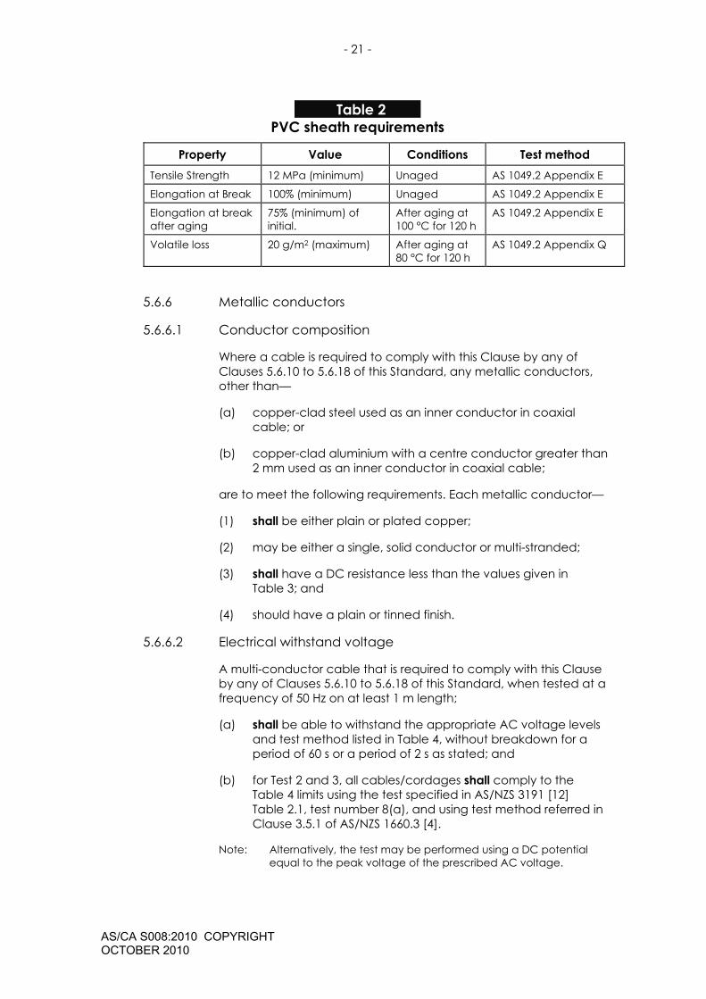
Table 2 PVC sheath requirements
Property Value Conditions Test method Tensile Strength 12 MPa (minimum) Unaged AS 1049.2 Appendix E
Elongation at Break 100% (minimum) Unaged AS 1049.2 Appendix E
Elongation at break after aging
75% (minimum) of initial.
After aging at 100 °C for 120 h
AS 1049.2 Appendix E
Volatile loss 20 g/m2 (maximum) After aging at 80 °C for 120 h
AS 1049.2 Appendix Q
5.6.6 Metallic conductors
5.6.6.1 Conductor composition
Where a cable is required to comply with this Clause by any of Clauses 5.6.10 to 5.6.18 of this Standard, any metallic conductors, other than—
(a) copper-clad steel used as an inner conductor in coaxial cable; or
(b) copper-clad aluminium with a centre conductor greater than 2 mm used as an inner conductor in coaxial cable;
are to meet the following requirements. Each metallic conductor—
(1) shall be either plain or plated copper;
(2) may be either a single, solid conductor or multi-stranded;
(3) shall have a DC resistance less than the values given in Table 3; and
(4) should have a plain or tinned finish.
5.6.6.2 Electrical withstand voltage
A multi-conductor cable that is required to comply with this Clause by any of Clauses 5.6.10 to 5.6.18 of this Standard, when tested at a frequency of 50 Hz on at least 1 m length;
(a) shall be able to withstand the appropriate AC voltage levels and test method listed in Table 4, without breakdown for a period of 60 s or a period of 2 s as stated; and
(b) for Test 2 and 3, all cables/cordages shall comply to the Table 4 limits using the test specified in AS/NZS 3191 [12] Table 2.1, test number 8(a), and using test method referred in Clause 3.5.1 of AS/NZS 1660.3 [4].
Note: Alternatively, the test may be performed using a DC potential equal to the peak voltage of the prescribed AC voltage.

- 22 -
AS/CA S008:2010 COPYRIGHT OCTOBER 2010
Table 3 Conductor resistance
Wire type Resistance Ω/km @ 20ºC
Single strand of plain annealed copper 24/d²
Single strand of plated annealed copper 26/d²
Bunched strands of plain or plated copper 28/N.d²
where: N is the number of strands
d is nominal diameter of individual strands or solid single strand in millimetres
Note 1: The DC resistance is based on the diameter of the strand, or in the case of multi stranded conductors, on the number of strands and the diameter of the individual strands.
Note 2: The recommended conductor diameter for copper conductors is in the range 0.4 mm to 0.9 mm.
Table 4 Cable withstand voltages
Test number High voltage test Cordage
(kV a.c.)
Indoor cable
(kV a.c.)
Outdoor cable
(kV a.c.)
1
Conductor to core Test voltage applied between each conductor and all remaining conductors and to shield if applicable.
0.7 (or 1.7 for 2 s) 1.5 2.0
2
Core to sheath Test voltage applied between all conductors bunched together and sheath exterior or SWA if applicable.
0.7 (or 1.7 for 2 s) 3.0 4.5
3 Shield to sheath (where applicable) Test voltage applied between shield and sheath exterior.
1.5 3.0 4.5
5.6.6.3 Mutual capacitance
Where a cable is required to comply with this Clause by any of Clauses 5.6.10 to 5.6.18 of this Standard, the following requirements are to be met:
(a) The maximum mutual capacitance between the two wires forming a pair measured at any frequency in the range 800 Hz to 1000 Hz shall not exceed the relevant value given in Table 5.
(b) The measurement, referred to in Clause 5.6.6.3(a) shall be performed on a minimum cable length of 100 m, in

- 23 -
AS/CA S008:2010 COPYRIGHT OCTOBER 2010
accordance with Clause 5.4 of IEC 60189-1 [22] except as varied in Clause 5.6.6.3(c) below.
(c) The mutual capacitance shall be corrected to a length of 1000 m by application of the following equation:
L1000valuemeasuredlengthm1000tocorrectedValue ×=
where: L is the length in metres of the cable under test
5.6.6.4 Capacitance unbalance
Where a cable is required to comply with this Clause by any of Clauses 5.6.10 to 5.6.18 of this Standard, the following requirements are to be met:
(a) The maximum capacitance unbalance between pairs measured at any frequency in the range 800 Hz to 1000 Hz shall not exceed the relevant value given in Table 5.
(b) During the measurement referred to in Clause 5.6.6.4(a), all conductors, other than those under test and the metallic shield (where applicable) shall be connected to earth.
(c) The measurement shall be performed on a minimum cable length of 100 m, in accordance with Clause 5.5 of IEC 60189-1 [22] except as varied in Clause 5.6.6.4(e) below.
(d) The capacitance unbalance between two pairs of wires with one pair designated ‘A’ and ‘B’ and the second pair designated ‘C’ and ‘D’ is given by the following expression:
(W + Y) – (X + Z)
where: W is the capacitance between the ‘A’ and ‘C’ wires
Z is the capacitance between the ‘A’ and ‘D’ wires
X is the capacitance between the ‘B’ and ‘C’ wires
Y is the capacitance between the ‘B’ and ‘D’ wires
(e) The capacitance unbalance shall be corrected to a length of 500 m by application of the following equation:
500
valuemeasuredlengthm500tocorrectedValueL
=
where: L is the length in metres of the cable under test
5.6.6.5 Insulation resistance
Where a cable is required to comply with this Clause by any of Clauses 5.6.10 to 5.6.18 of this Standard, the minimum insulation
- 24 -
AS/CA S008:2010 COPYRIGHT OCTOBER 2010
resistance between any two conductors forming a pair, a quad or a coaxial tube—
(a) shall not be less than the relevant value given in Table 5;
(b) the measurement shall be made on a minimum length of 100 m of cable or cordage at a potential of 500 V d.c. ±50 V d.c. and the reading taken after the application of the voltage for 60 s; and
(c) the insulation resistance shall be corrected to a length of 1000 m by application of the following equation:
1000L
×= valuemeasuredlengthm1000tocorrectedValue
where: L is the length in metres of the cable under test
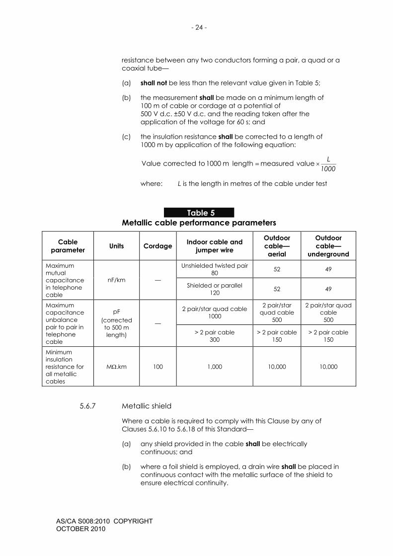
Table 5
Metallic cable performance parameters
Cable parameter Units Cordage Indoor cable and
jumper wire
Outdoor cable— aerial
Outdoor cable—
underground Unshielded twisted pair
80 52 49 Maximum mutual capacitance in telephone cable
nF/km — Shielded or parallel
120 52 49
2 pair/star quad cable 1000
2 pair/star quad cable
500
2 pair/star quad cable
500
Maximum capacitance unbalance pair to pair in telephone cable
pF (corrected to 500 m length)
— > 2 pair cable
300 > 2 pair cable
150 > 2 pair cable
150
Minimum insulation resistance for all metallic cables
MΩ.km 100 1,000 10,000 10,000
5.6.7 Metallic shield
Where a cable is required to comply with this Clause by any of Clauses 5.6.10 to 5.6.18 of this Standard—
(a) any shield provided in the cable shall be electrically continuous; and
(b) where a foil shield is employed, a drain wire shall be placed in continuous contact with the metallic surface of the shield to ensure electrical continuity.
- 25 -
AS/CA S008:2010 COPYRIGHT OCTOBER 2010
Note: Annex J of AS/NZS 60950.1 [19] gives recommendations for avoiding certain combinations of metals that could lead to corrosion.
5.6.8 Water penetration test
A cable that is required to comply with this Clause by AS/ACIF S009 [20] or by any of Clauses 5.6.10 to 5.6.18 of this Standard shall comply with the requirements for Water Penetration specified in Clause 25, Method –F5B of IEC 60794-1-2 [28].
Note 1: Water penetration refers to the effectiveness of a cable in restricting the longitudinal movement of water or moisture along the core. This requirement is primarily intended to localise any water penetration to minimise the adverse effect on cable performance and to prevent water or moisture leaking into joints and terminations that may cause corrosion problems.
Note 2: Additionally, cable installed underground should have a high-density compound sheath material (such as polyethylene) that provides an adequate barrier to moisture entry to the cable core. The addition of a lapped metal tape (‘moisture barrier’) and/or grease or gel within the core (‘filled’ or ‘flooded’ cable) provides even higher protection against moisture entry.
Note 3: Cable susceptible to ant/termite attack or that is buried directly in the ground without conduit should be of a type that provides additional mechanical protection against abrasion and insects such as a nylon jacket with an optional sacrificial jacket.
Note 4: Not all cables marketed as ‘outdoor’ or ‘indoor/outdoor’ cables meet the water penetration requirements for underground use. Manufacturers should clearly identify products intended to be installed underground.
Compliance testing for water penetration using method –F5B can be conducted without the bending pre-conditioning of the cable under test.
5.6.9 Integral bearer or strengthener
A cable that is intended for aerial use may contain an integral bearer or strengthener. Where an integral bearer/strengthener is provided:
(a) The cable sheath shall fit closely over, but not adhere to, the bearer/strengthener.
Note: The sheath over the integral bearer/strengthener may be of cottage-loaf (i.e. figure-of-eight) construction.
(b) The strength of the bearer/strengthener shall be sufficient to carry the load of the cable under the specified conditions.
(c) The specified conditions referred to in Item (b) shall be stated in a product data sheet.

- 26 -
AS/CA S008:2010 COPYRIGHT OCTOBER 2010
(d) The product data sheet shall state the maximum allowable span, tension, sag, wind speed, ambient temperature range, and other parameters applicable to its use.
Note: Some of the data should be provided in the form of a table specifying, for example, allowable tension/sag values at various span lengths and temperatures.
5.6.10 Cable with specific attributes
Where a cable is claimed to have specific attributes, such as rodent or termite resistance or armouring strength, evidentiary documentation shall be made available on request to support the claim.
Compliance is assessed by the manufacturer’s declaration stating the basis of the declaration, which may include known properties of the materials used.
5.6.11 Metallic paired cable
5.6.11.1 General requirements
Metallic paired cable, other than cordage, a cord or a special application cable, shall comply with the following Clauses:
5.6.2 Conductor and optical fibre identification 5.6.3 Insulation and sheath material 5.6.4 Flammability (if intended for use within a building) 5.6.5 UV resistance (if intended for use external to a building,
including underground) 5.6.6.1 Conductor composition 5.6.6.2 Electrical withstand voltage 5.6.6.3 Mutual capacitance (if intended for use as a
telephone cable) 5.6.6.4 Capacitance unbalance (if intended for use as a
telephone cable) 5.6.6.5 Insulation resistance 5.6.7 Metallic shield (if applicable) 5.6.8 Water penetration test (if intended for use
underground) 5.6.9 Integral bearer or strengthener (if intended for aerial
use without a separate catenary support)
5.6.11.2 Construction
A cable intended to carry a frequency of 300 Hz or greater shall be shielded or of twisted pair construction.

- 27 -
AS/CA S008:2010 COPYRIGHT OCTOBER 2010
5.6.12 Cordage with metallic conductors
5.6.12.1 General requirements
Cordage with metallic conductors shall comply with the following Clauses:
5.6.2 Conductor and optical fibre identification 5.6.3 Insulation and sheath material 5.6.4 Flammability 5.6.5 UV resistance (if intended for use external to a building) 5.6.6.1 Conductor composition 5.6.6.2 Electrical withstand voltage 5.6.6.3 Mutual capacitance (if intended for use as telephone
cordage) 5.6.6.4 Capacitance unbalance (if intended for use as
telephone cordage) 5.6.6.5 Insulation resistance 5.6.7 Metallic shield (if applicable)
5.6.12.2 Conductor composition
Conductors in metallic cordage should be of stranded or tinsel conductor construction when frequent movement of the cordage is anticipated.
5.6.13 Cords with metallic conductors
5.6.13.1 General requirements
A cord with metallic conductors shall comply with the following Clauses:
5.6.2 Conductor and optical fibre identification 5.6.4 Flammability 5.6.5 UV resistance (if intended for use external to a building) 5.6.6.1 Conductor composition 5.6.6.2 Electrical withstand voltage 5.6.6.5 Insulation resistance 5.6.7 Metallic shield (if applicable)
5.6.13.2 Cords exceeding a length of 10 m
A cord with metallic conductors that exceeds a length of 10 m shall comply with Clause 5.6.13.1 and the following Clauses:
5.6.3 Insulation and sheath material 5.6.6.3 Mutual capacitance (if intended for use as a
telephone cord) 5.6.6.4 Capacitance unbalance (if intended for use as a
telephone cord)
- 28 -
AS/CA S008:2010 COPYRIGHT OCTOBER 2010
5.6.13.3 Cord anchorage or strain relief
A cord with metallic conductors—
(a) shall be secured in any plug or socket connected to a cord by an appropriate anchorage or strain relief; and
(b) when subjected to a force of 45 N gradually applied between the cord and the plug or socket for a period of 60 s, the cord shall not be longitudinally displaced by more than 2 mm, nor show any appreciable strain at the connection.
Note: For measurement of longitudinal displacement, a mark is made on the cord approximately 20 mm from the cord anchorage or other suitable point before the test. The displacement of the mark is measured 60 s after the removal of the force from the cord.
5.6.14 Metallic jumper wire and jumper cable
5.6.14.1 General requirements
Metallic jumper wire and jumper cable shall comply with the following Clauses:
5.6.2 Conductor and optical fibre identification 5.6.3 Insulation and sheath material 5.6.4 Flammability 5.6.6.1 Conductor composition 5.6.6.2 Electrical withstand voltage 5.6.6.5 Insulation resistance 5.6.7 Metallic shield (if applicable)
5.6.14.2 Twist rate
Metallic jumper wire and cable shall have a minimum of 13 twists/metre in each pair.
5.6.15 Coaxial cable
5.6.15.1 General requirements
Coaxial cable shall comply with the following Clauses:
5.6.2 Conductor and optical fibre identification (if applicable, i.e. contains more than one coaxial tube)
5.6.3 Insulation and sheath material 5.6.4 Flammability (if intended for use within a building) 5.6.5 UV resistance (if intended for use external to a building,
including underground) 5.6.6.1 Conductor composition 5.6.6.2 Electrical withstand voltage 5.6.6.5 Insulation resistance 5.6.7 Metallic shield
- 29 -
AS/CA S008:2010 COPYRIGHT OCTOBER 2010
5.6.9 Integral bearer or strengthener (if intended for aerial use without a separate catenary support)
Note: Coaxial cable intended for underground use is not required to meet the water penetration test of Clause 5.6.8 but should be of the ‘flooded’ type.
5.6.15.2 Velocity ratio
The velocity ratio, determined according to Clause 13 of IEC 60096-1 [21], shall be a minimum of 0.65.
5.6.15.3 Characteristic impedance
The characteristic impedance, measured according to Clause 14 of IEC 60096-1 [21], shall be Zo ± Zo/25, where Zo is the nominal characteristic impedance specified by the manufacturer.
5.6.15.4 Attenuation
The attenuation should be less than or equal to that specified by the manufacturer at 200 MHz when measured in accordance with Clause 16 of IEC 60096-1 [21].
5.6.16 Optical fibre cable
5.6.16.1 General requirements
Optical fibre cable, other than a blown fibre tube system, shall comply with the following Clauses:
5.6.2 Conductor and optical fibre identification 5.6.3 Insulation and sheath material (sheath requirement
only) 5.6.4 Flammability (if intended for use within a building) 5.6.5 UV resistance (if intended for use external to a building,
including underground) 5.6.8 Water penetration test (if intended for use
underground) 5.6.9 Integral bearer or strengthener (if intended for aerial
use without a separate catenary support)
5.6.16.2 Fibre requirements
Multimode and single-mode fibres shall meet the relevant requirements of IEC 60793-2 [26].
5.6.16.3 Mechanical and environmental performance
The supplier shall make available to the customer, on request, a Product Data Sheet as per the appropriate procedures in IEC 60794-1-1 [27], specifying the mechanical and the environmental performance of a particular cable design.

- 30 -
AS/CA S008:2010 COPYRIGHT OCTOBER 2010
5.6.16.4 Optical fibre cords
Optical fibre cordage shall be secured in any plug or socket by an appropriate anchorage or strain relief so that when subjected to a force of 45 N gradually applied between the cordage and the plug or socket for a period of 60 s, the cordage shall not be longitudinally displaced by more than 2 mm, nor show any appreciable strain at the connection.
Note: For measurement of longitudinal displacement, a mark is made on the cordage approximately 20 mm from the cordage anchorage or other suitable point before the test and the displacement of the mark is measured while the cord is subjected to the pull.
5.6.17 Blown fibre tube systems
5.6.17.1 General requirements
A blown fibre tube system shall comply with the following Clauses:
5.6.2 Conductor and optical fibre identification 5.6.3 Insulation and sheath material 5.6.4 Flammability (if intended for use within a building) 5.6.5 UV resistance (if intended for use external to a building,
including underground) 5.6.9 Integral bearer or strengthener (if intended for aerial
use without a separate catenary support)
Note: A blown fibre tube system has characteristics that are distinct from those of conventional cable and is therefore exempt from the water penetration test of Clause 5.6.8 when used underground.
5.6.17.2 Outer tube or sheath
The outer tube or sheath of an underground blown fibre tube system shall comply with the requirements of IPX8 of AS 60529 [16].
5.6.18 Special application cables
5.6.18.1 Compliance
A cable intended for a special application and intended for use in a cabling system connected to a carrier’s network shall—
(a) comply with Clauses 5.6.18.2 and 5.6.18.3; and
(b) have insulation, sheath and jacket material that complies with AS 1049.1 [2] when tested to AS 1049.2 [2].
5.6.18.2 General requirements
A special application cable installed within a building shall comply with Clause 5.6.4.

- 31 -
AS/CA S008:2010 COPYRIGHT OCTOBER 2010
5.6.18.3 Cable with metallic conductors
A special application cable with metallic conductors—
(a) shall comply with the testing requirements of the relevant Standard, in order of priority, from Australian/New Zealand Standard or ISO/IEC Standard or other national published Standard applicable to that particular type of cable, as listed by way of example in Table 6, to meet the requirements for its intended use; or
(b) where Clause 5.6.18.3(a) is not applicable—
(i) the cable should comply with the following Clauses of this Standard:
5.6.6.1 Conductor composition; 5.6.6.2 Electrical withstand voltage; 5.6.6.5 Insulation resistance; 5.6.7 Metallic shield (if applicable); and
(ii) where the cable is intended to be used as a telephone cable, it shall comply with the following Clauses of this Standard:
5.6.6.3 Mutual capacitance; 5.6.6.4 Capacitance unbalance.
- 32 -
AS/CA S008:2010 COPYRIGHT OCTOBER 2010
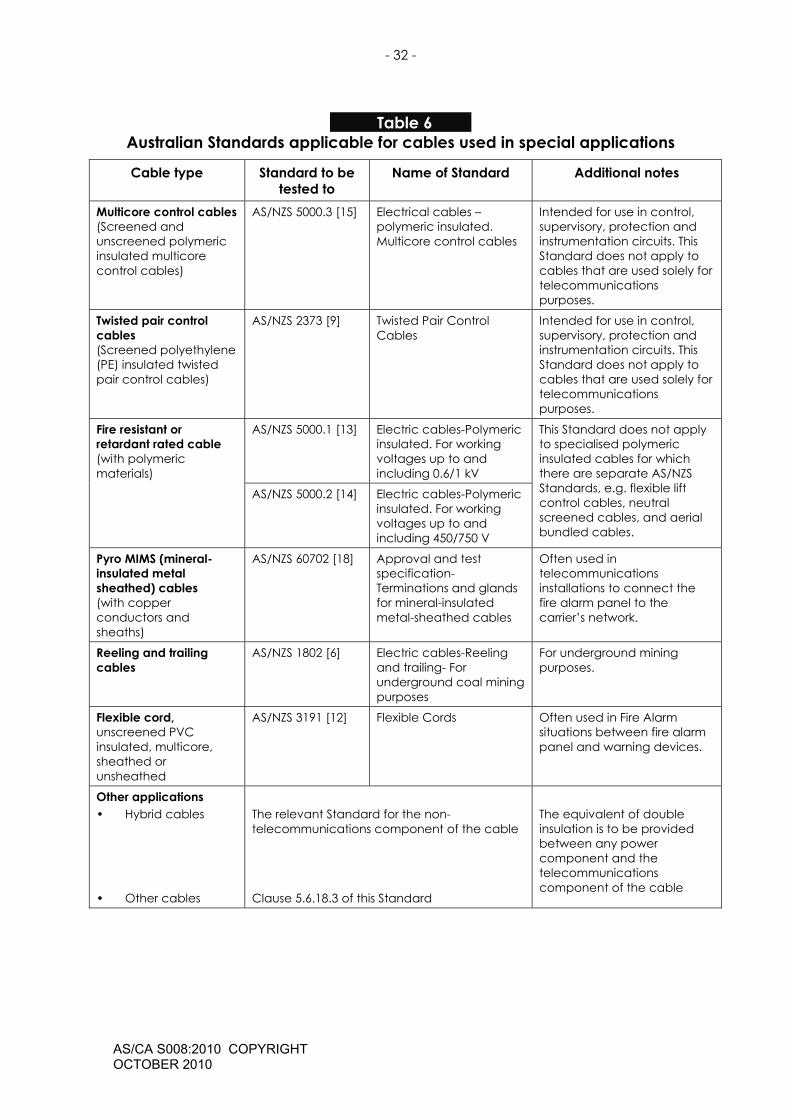
Table 6 Australian Standards applicable for cables used in special applications
Cable type Standard to be tested to
Name of Standard Additional notes
Multicore control cables (Screened and unscreened polymeric insulated multicore control cables)
AS/NZS 5000.3 [15] Electrical cables – polymeric insulated. Multicore control cables
Intended for use in control, supervisory, protection and instrumentation circuits. This Standard does not apply to cables that are used solely for telecommunications purposes.
Twisted pair control cables (Screened polyethylene (PE) insulated twisted pair control cables)
AS/NZS 2373 [9] Twisted Pair Control Cables
Intended for use in control, supervisory, protection and instrumentation circuits. This Standard does not apply to cables that are used solely for telecommunications purposes.
AS/NZS 5000.1 [13] Electric cables-Polymeric insulated. For working voltages up to and including 0.6/1 kV
Fire resistant or retardant rated cable (with polymeric materials)
AS/NZS 5000.2 [14] Electric cables-Polymeric insulated. For working voltages up to and including 450/750 V
This Standard does not apply to specialised polymeric insulated cables for which there are separate AS/NZS Standards, e.g. flexible lift control cables, neutral screened cables, and aerial bundled cables.
Pyro MIMS (mineral-insulated metal sheathed) cables (with copper conductors and sheaths)
AS/NZS 60702 [18] Approval and test specification-Terminations and glands for mineral-insulated metal-sheathed cables
Often used in telecommunications installations to connect the fire alarm panel to the carrier’s network.
Reeling and trailing cables
AS/NZS 1802 [6] Electric cables-Reeling and trailing- For underground coal mining purposes
For underground mining purposes.
Flexible cord, unscreened PVC insulated, multicore, sheathed or unsheathed
AS/NZS 3191 [12] Flexible Cords Often used in Fire Alarm situations between fire alarm panel and warning devices.
Other applications • Hybrid cables
• Other cables
The relevant Standard for the non-telecommunications component of the cable Clause 5.6.18.3 of this Standard
The equivalent of double insulation is to be provided between any power component and the telecommunications component of the cable
- 33 -
AS/CA S008:2010 COPYRIGHT OCTOBER 2010
5.7 Connecting hardware, including plugs and sockets of all designs
5.7.1 General
5.7.1.1 Insulation resistance
The insulation resistance between any two points which are required to be electrically insulated shall be a minimum of 100 MΩ. The insulation resistance measurement is to be made after 500 V ± 50 V d.c. has been applied for a period of 60 s.
Compliance with Clause 5.7.1.1 should be checked using the method specified in IEC 60512-3-1 [24].
5.7.1.2 Contact resistance
5.7.1.2.1 Insulation Displacement contacts
The contact resistance of the interface between a single insulated solid or stranded conductor and a single Insulation Displacement (ID) contact in connecting hardware other than the types of plugs and sockets covered in Clauses 5.7.2, 5.7.3 and 5.7.4 shall comply with the requirements of IEC 60352-4 [23] Clause 12.3.1, including Table 2 of that Clause.
5.7.1.2.2 Plug and socket connection
For connectors using a plug and socket, including the connection of shield or drain-wire conductors, other than the types of plugs and sockets described in Clauses 5.7.2, 5.7.3 and 5.7.4, the interface resistance of the overall mated connection or shield connection shall not exceed 50 mΩ when measured between the cord terminated on the plug and the cable terminated on the socket using the test method described in Clause 12.3.1 of IEC 60352-4 [23].
Note: Appendix J of AS/NZS 60950.1 [19] gives recommendations for avoiding certain combinations of different metals, the combination of which could lead to corrosion.
5.7.1.3 Electric strength
Electrically conductive elements normally at telecommunications network voltage (TNV) shall comply with Clause 6.2.2 (Voltage proof) of IEC 60603-7 [25].
5.7.1.4 Protection against contact with exposed circuits
Connectors, plugs and sockets with metallic conductors and shields shall comply with the probe test of Clause 6.2.1(b) (Separation requirements) of AS/NZS 60950.1 [19].
5.7.1.5 Weather resistance
Plugs and sockets intended for use in situations exposed to weather and damp areas shall have a minimum degree of protection of IPX3

- 34 -
AS/CA S008:2010 COPYRIGHT OCTOBER 2010
against the ingress of water when tested in accordance with AS 60529 [16].
Compliance with Clause 5.7.1.5 should be checked with a plug both inserted into and removed from the socket.
5.7.1.6 Access to cable terminations
All telecommunications terminations shall be enclosed or located to prevent unintentional contact with voltages other than SELV by a person who is not doing cabling work (e.g. an end-user).
Note: It is permissible to allow end-users to come into personal contact with SELV circuits although this should be prevented where practicable.
5.7.1.7 Prohibited arrangements
A connecting device's faceplate for telecommunications wiring shall not incorporate a low voltage fixed socket-outlet or switch.
Note: This is also a prohibited arrangement under AS/NZS 3112 [11].
5.7.2 Eight (8) position modular plugs and sockets
In addition to the general requirements of Clause 5.7.1, eight (8) position modular plugs and sockets shall comply with the following Clauses of IEC 60603-7 [25]:
6.4.2 Voltage proof
6.4.3 Current - temperature derating
6.4.4 Initial contact resistance
6.6.1 Mechanical operation (Cycle)
6.6.2 Effectiveness of a connector coupling device
5.7.3 Six (6) position modular plugs and sockets
Six (6) position modular plugs and sockets shall—
(a) be mechanically designed according to CFR FCC 47—68.500(a) and (b) [29]; and
(b) in addition to the general requirements of Clause 5.7.1, shall comply with the following Clauses of IEC 60603-7 [25]:
6.4.2 Voltage proof
6.4.3 Current - temperature derating
6.4.4 Initial contact resistance
6.6.1 Mechanical operation (Cycle)
6.6.2 Effectiveness of a connector coupling device
- 35 -
AS/CA S008:2010 COPYRIGHT OCTOBER 2010
5.7.4 600 series plugs and sockets
600 series sockets are not supported for new installations.
600 series plugs and sockets manufactured to support existing installations shall comply with Appendix A.
5.8 Cabling products for underground and aerial installations
5.8.1 Pits
The following requirements apply to pits:
(a) The mechanical integrity of pits shall not be adversely affected by long-term exposure to moisture and sunlight (UV radiation).
(b) When subjected to two single drop tests, one on the bottom and one on the side, from a height of 3 m onto a 3 mm thick steel plate, the pit shall not fracture.
(c) When subjected to a vertically applied compressive load of 5 kN centrally applied by a 100 mm x 100 mm plate the pit shall maintain its structural integrity.
(d) When subjected to a horizontally applied compressive force of 5 kN applied over the area of the larger side, the pit will maintain its structural integrity and shall not suffer from distortion of the rim.
(e) Entry holes for conduits should be capable of being sealed to prevent siltation of the pit.
(f) The pit cover shall be legibly and permanently labelled with the word ‘Communications’ or ‘Comms’, to distinguish it from pits of other services.
Compliance with Clause 5.8.1(a) should be checked on the basis of known properties of the materials used.
Compliance with Clauses 5.8.1(c) and (d) should be checked with the pit lid in place, any joint supports included and cable entry knockouts removed.
5.8.2 Underground joint/termination enclosures
The following requirements apply to underground joint/termination enclosures:
(a) Underground enclosures shall provide protection of the joint or termination of at least IPX8 in accordance with AS 60529 [16], with test conditions to simulate normal conditions of use.
(b) The test shall be carried out with a depth of 500 mm of water for a duration of 24 hours.
(c) Enclosures which are re-openable shall be opened and closed 10 times prior to the test.
- 36 -
AS/CA S008:2010 COPYRIGHT OCTOBER 2010
(d) Terminations may form part of the enclosure or they may be separate. In either case the terminations shall be protected to at least IPX8 in accordance with AS 60529 [16] when installed in the enclosure. See Clause 5.8.2(a) above.
Note: For testing purposes, cable may be required to be supplied by the manufacturer.
5.8.3 Underground and aerial cable terminations
Underground and aerial terminations shall comply with Clauses 5.7.1.1 to 5.7.1.4.
5.8.4 Pillars and cabinets
The following requirements apply to pillars and cabinets:
(a) The mechanical integrity of pillars and cabinets shall not be adversely affected by long-term exposure to moisture and sunlight (UV radiation).
Compliance with Clause 5.8.4(a) should be checked on the basis of known properties of the materials used.
(b) Pillars and cabinets shall provide protection of at least IPX3 in accordance with AS 60529 [16] after opening and closing 10 times prior to the test.
(c) Provision shall be made for locking pillars and cabinets.
(d) Terminations within pillars and cabinets shall comply with Clauses 5.7.1.1 to 5.7.1.4.
(e) Pillars and cabinets should be legibly and permanently labelled to distinguish them from those used for other services.
5.8.5 Aerial joint/termination enclosures
The following requirements apply to aerial joint/termination enclosures:
(a) Aerial enclosures shall provide protection of the joint or termination of at least IPX3 in accordance with AS 60529 [16].
(b) Enclosures that are re-openable shall be opened and closed 10 times prior to the test.
(c) Covers of aerial enclosures should be removable to allow access to terminations when installed.
(d) Aerial enclosures shall provide double insulation from internal terminations to 240 V a.c. grade in accordance with AS/NZS 60950.1 [19].
(e) The mechanical integrity of aerial enclosures shall not be adversely affected by long-term exposure to weather and sunlight (UV radiation).
- 37 -
AS/CA S008:2010 COPYRIGHT OCTOBER 2010
Compliance with Clause 5.8.5(e) should be checked is assessed on the basis of known properties of the materials used.
(f) Terminations may form part of the aerial enclosure or may be separate. In either case the terminations shall be protected to at least IPX3 in accordance with AS 60529 [16] when installed in the enclosure.
Note: Terminations in aerial enclosures also need to comply with Clauses 5.7.1.1 to 5.7.1.4.

- 38 -
AS/CA S008:2010 COPYRIGHT OCTOBER 2010
APPENDIX A (Normative) 600 SERIES PLUGS AND SOCKETS
A.1 General
600 series sockets are not supported for new installations. See Clause 5.7.4 of this Standard.
600 series plugs and sockets that are manufactured to support existing installations shall comply with this Appendix A.2 to A.5.
Note: Appendix C of AS/ACIF S009 [20] provides more information about 600 series sockets.
A.2 Contact composition
Contact metal shall be composed of solid Monel Alloy 400 in accordance with the standard composition of nickel copper alloy type NA 13.
A.3 Mechanical compatibility
Sockets should be designed to accept one or more of the 600 series plugs. The nominal mating dimensions of 600 series plugs and sockets shall be in accordance with Figure A1.
Note: Sockets may incorporate switching facilities that operate on the insertion and withdrawal of the plug.
A.4 Connections
Plugs and sockets shall have, as a minimum, electrical connections corresponding to contacts 2 and 6 in accordance with Figure A1.
A.5 Resistance of plug/socket combination
With the plug inserted into the socket, the maximum resistance between the cord terminated onto the plug and the cable terminated onto the socket shall not exceed 50 mΩ when tested with an applied voltage not exceeding 50 mV d.c. and an applied current not exceeding 100 mA.

- 39 -
AS/CA S008:2010 COPYRIGHT OCTOBER 2010
SECTION A-A
4321 5 6
12.513
6.7
9.5
9.519.8 TYPICAL2.46 +0.25
-0.35
A
A
7
B
B
13.56
2 3 4 5 61
2.9
3.2
0.8
3.2
7.2
SECTION B-B
12.8
6.74
Note 1: On both views, the cover has been removed for clarity.
Note 2: Dimensions are in mm.
Figure A1 1
Mating dimensions for 600 series plugs and sockets

- 40 -
AS/CA S008:2010 COPYRIGHT OCTOBER 2010
APPENDIX B (Informative) CABLE COLOUR CODES Common colour codes for various types of cable are described in AS/ACIF S009 [20] Tables B1 to B7. These tables are reproduced here to provide continuity between the Standards. Cable manufacturers usually follow these colour codes. Cables are required to use some method of coding that enables pairs and conductors to be visually distinguishable from one another (refer to Clause 5.6.2 of this Standard) but it is not mandatory for cable manufacturers to follow these colour codes.
Table B1 7 2-pair (quad) and 3-pair telephone cable colour code
Pair Number Colours
1 White Blue
2 Red
Black
3 Orange Green
Table B2 8 1-pair to 5-pair cable colour code
Pair number Colour code variations 1 White
Blue White-Blue
Blue White-Blue * Blue-White *
2 White Orange
White-Orange Orange
White-Orange * Orange-White *
3 White Green
White-Green Green
White-Green * Green-White *
4 White Brown
White-Brown Brown
White-Brown * Brown-White *
5 White Grey
White-Grey Grey
White-Grey * Grey-White *
* The first-named colour is the predominant colour
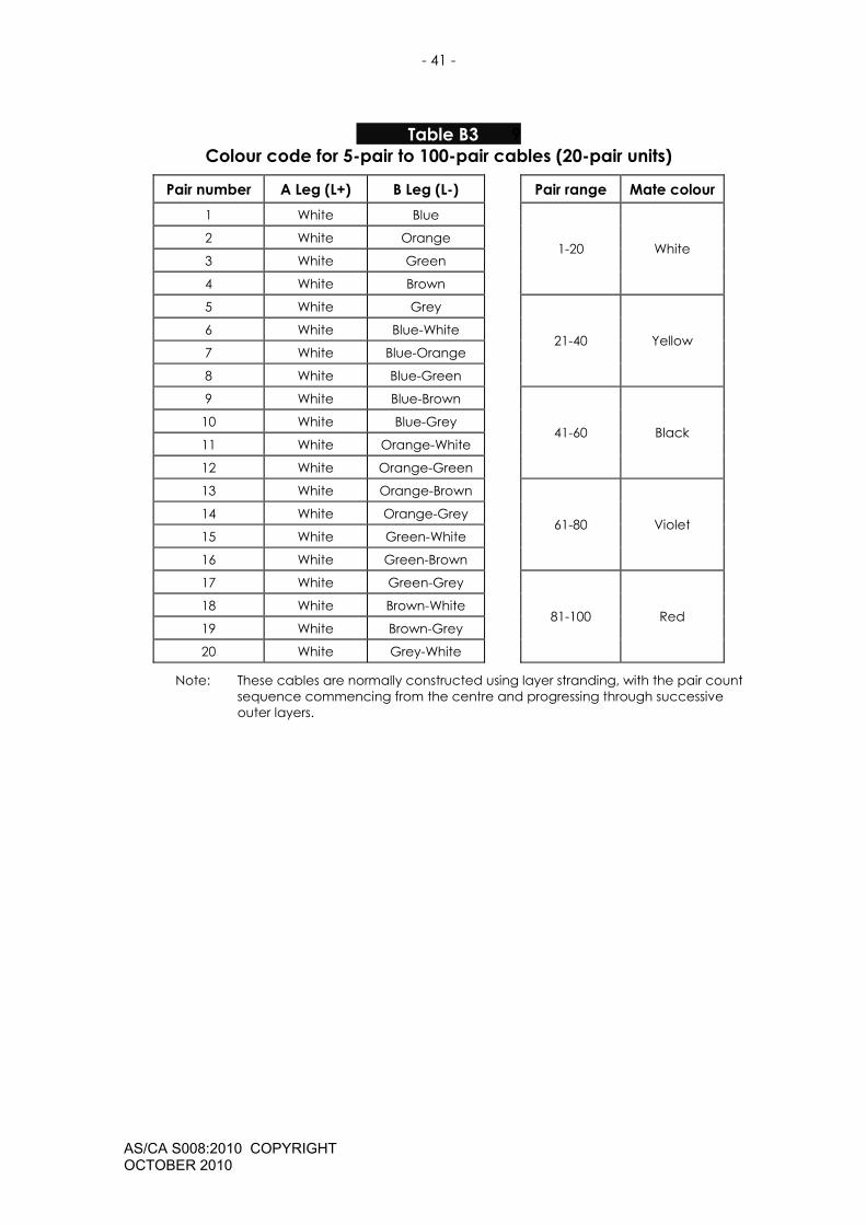
- 41 -
AS/CA S008:2010 COPYRIGHT OCTOBER 2010
Table B3 9 Colour code for 5-pair to 100-pair cables (20-pair units)
Pair number A Leg (L+) B Leg (L-) Pair range Mate colour 1 White Blue
2 White Orange
3 White Green
4 White Brown
1-20 White
5 White Grey
6 White Blue-White
7 White Blue-Orange
8 White Blue-Green
21-40 Yellow
9 White Blue-Brown
10 White Blue-Grey
11 White Orange-White
12 White Orange-Green
41-60 Black
13 White Orange-Brown
14 White Orange-Grey
15 White Green-White
16 White Green-Brown
61-80 Violet
17 White Green-Grey
18 White Brown-White
19 White Brown-Grey
20 White Grey-White
81-100 Red
Note: These cables are normally constructed using layer stranding, with the pair count sequence commencing from the centre and progressing through successive outer layers.
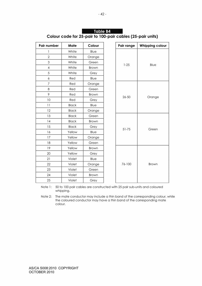
- 42 -
AS/CA S008:2010 COPYRIGHT OCTOBER 2010
Table B4 10 Colour code for 25-pair to 100-pair cables (25-pair units)
Pair number Mate Colour Pair range Whipping colour 1 White Blue
2 White Orange
3 White Green
4 White Brown
5 White Grey
6 Red Blue
1-25 Blue
7 Red Orange
8 Red Green
9 Red Brown
10 Red Grey
11 Black Blue
12 Black Orange
26-50 Orange
13 Black Green
14 Black Brown
15 Black Grey
16 Yellow Blue
17 Yellow Orange
18 Yellow Green
51-75 Green
19 Yellow Brown
20 Yellow Grey
21 Violet Blue
22 Violet Orange
23 Violet Green
24 Violet Brown
25 Violet Grey
76-100 Brown
Note 1: 50 to 100 pair cables are constructed with 25 pair sub-units and coloured whipping.
Note 2: The mate conductor may include a thin band of the corresponding colour, while the coloured conductor may have a thin band of the corresponding mate colour.

- 43 -
AS/CA S008:2010 COPYRIGHT OCTOBER 2010
Table B5 11 Colour code for 5-pair to 100-pair cables (10-pair units)
Pair number A Leg (L+) B Leg (L-) Pair range Whipping colour 1 White Blue 1-10 Blue
2 White Orange 11-20 Orange
3 White Green 21-30 Green
4 White Brown 31-40 Brown
5 White Grey 41-50 Grey
6 Red Blue 51-60 Blue-White
7 Red Orange 61-70 Orange-White
8 Red Green 71-80 Green-White
9 Red Brown 81-90 Brown-White
10 Red Grey 91-100 Grey-White
Table B6 12 Colour code for 5-pair to 200-pair cables (10-pair units)
Pair number A Leg (L+) B Leg (L-) Pair range Whipping colour 1-10 Blue-White
1 White Blue 11-20 Orange-White
21-30 Green-White 2 White Orange
31-40 Brown-White
41-50 Grey-White 3 White Green
51-60 Blue-Blue
61-70 Orange-Orange 4 White Brown
71-80 Green-Green
81-90 Brown-Brown 5 White Grey
91-100 Grey-Grey
101-110 White-White 6 Red Blue
111-120 Red-Red
121-130 Yellow-Yellow 7 Red Orange
131-140 Violet-Violet
141-150 Black-Black 8 Red Green
151-160 Blue-Red
161-170 Orange-Red 9 Red Brown
171-180 Green-Red
181-190 Brown-Red 10 Red Grey
191-200 Grey-Red
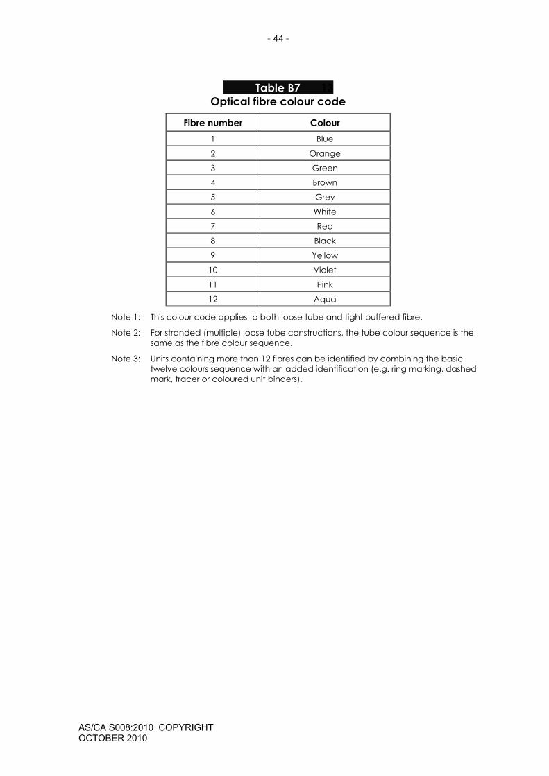
- 44 -
AS/CA S008:2010 COPYRIGHT OCTOBER 2010
Table B7 13 Optical fibre colour code
Fibre number Colour 1 Blue
2 Orange
3 Green
4 Brown
5 Grey
6 White
7 Red
8 Black
9 Yellow
10 Violet
11 Pink
12 Aqua
Note 1: This colour code applies to both loose tube and tight buffered fibre.
Note 2: For stranded (multiple) loose tube constructions, the tube colour sequence is the same as the fibre colour sequence.
Note 3: Units containing more than 12 fibres can be identified by combining the basic twelve colours sequence with an added identification (e.g. ring marking, dashed mark, tracer or coloured unit binders).
- 45 -
AS/CA S008:2010 COPYRIGHT OCTOBER 2010
6 PARTICIPANTS The Working Committee responsible for the revisions made to this Standard consisted of the following organisations:
Organisation Membership Australian Communications and Media Authority
Non-voting
Clipsal Voting
Electrical and Communications Association
Non-voting
International Testing and Certification Services (ITACS)
Voting
ADC Krone Voting
Optus Voting
Prysmian Voting
Telstra Voting
This Working Committee was chaired by Mike Johns of Communication Alliance, who also provided project management support.
- 46 -
AS/CA S008:2010 COPYRIGHT OCTOBER 2010
NOTES
Template version 3
Communications Alliance was formed in 2006 to provide a unified voice for the Australian communications industry and to lead it into the next generation of converging networks, technologies and services.
In pursuing its goals, Communications Alliance offers a forum for the industry to make coherent and constructive contributions to policy development and debate.
Communications Alliance seeks to facilitate open, effective and ethical competition between service providers while ensuring efficient, safe operation of networks, the provision of innovative services and the enhancement of consumer outcomes.
It is committed to the achievement of the policy objective of the Telecommunications Act 1997 - the greatest practicable use of industry self-regulation without imposing undue financial and administrative burdens on industry.
Published by: COMMUNICATIONS ALLIANCE LTD Level 9 32 Walker Street North Sydney NSW 2060 Australia Correspondence PO Box 444 Milsons Point NSW 1565 T 61 2 9959 9111 F 61 2 9954 6136 TTY 61 2 9923 1911 E [email protected] www.commsalliance.com.au ABN 56 078 026 507 Care should be taken to Care should be taken to ensure the material used is from the current version of the Standard or Industry Code and that it is updated whenever the Standard or Code is amended or revised. The number and date of the Standard or Code should therefore be clearly identified. If in doubt please contact Communications Alliance
ISBN: 1 74000 405 1
Related Documents