1 Aussie Hydrotek Steam Cleaners … Operation & Maintenance Manual June 2016 Australian Pump Industries SERIES HSS SERIES HSC SERIES HSCU Aussie Hydrotek Steam Cleaners OPERATION & MAINTENANCE MANUAL IMPORTANT: TO REDUCE RISK OF INJURY, READ OPERATING INSTRUCTIONS CAREFULLY BEFORE USING EQUIPMENT

Welcome message from author
This document is posted to help you gain knowledge. Please leave a comment to let me know what you think about it! Share it to your friends and learn new things together.
Transcript
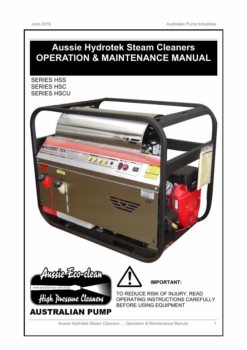
1 Aussie Hydrotek Steam Cleaners … Operation & Maintenance Manual
June 2016 Australian Pump Industries
SERIES HSS SERIES HSC SERIES HSCU
Aussie Hydrotek Steam Cleaners OPERATION & MAINTENANCE MANUAL
IMPORTANT: TO REDUCE RISK OF INJURY, READ OPERATING INSTRUCTIONS CAREFULLY BEFORE USING EQUIPMENT
2 Aussie Hydrotek Steam Cleaners … Operation & Maintenance Manual
Australian Pump Industries June 2016
TABLE OF CONTENTS
Introduction ........................................................................................................................... 3 Statement of Warranty
Safety Warnings ................................................................................................................... 4 Operating Instructions
Before start up ............................................................................................................ 6 Operation ................................................................................................................... 6 Shut Down & antifreeze protection ............................................................................ 8
System Information
Power system .............................................................................................................. 9 Pumping System ........................................................................................................ 9 Heating System .......................................................................................................... 11 Pressure Delivery System .......................................................................................... 12 Accessories ................................................................................................................ 13
Troubleshooting Guide ......................................................................................................... 16 Burner Troubleshooting guide .............................................................................................. 18 Service/Maintenance Information ......................................................................................... 20 Exploded Views & Parts Lists ............................................................................................. 21 Risk assessment forms ........................................................................................................ 30
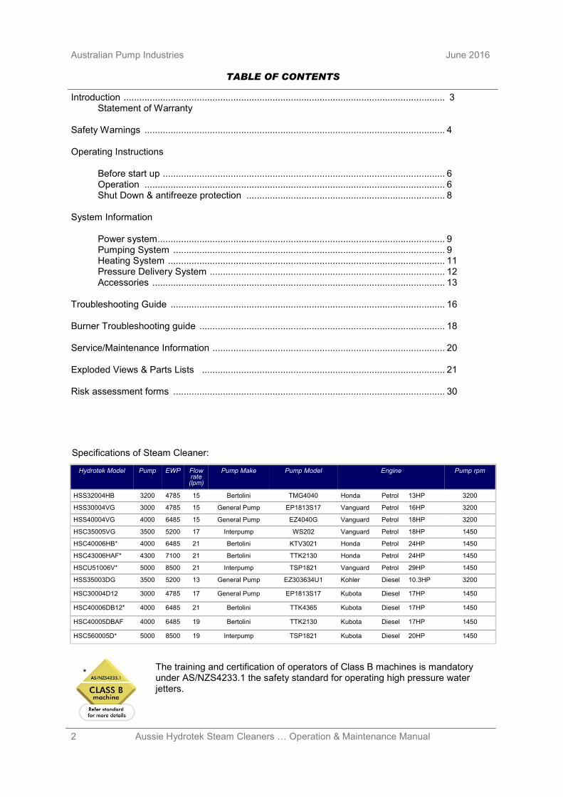
Specifications of Steam Cleaner:
Hydrotek Model Pump EWP Flow rate (lpm)
Pump Make Pump Model Engine Pump rpm
HSS32004HB 3200 4785 15 Bertolini TMG4040 Honda Petrol 13HP 3200
HSS30004VG 3000 4785 15 General Pump EP1813S17 Vanguard Petrol 16HP 3200
HSS40004VG 4000 6485 15 General Pump EZ4040G Vanguard Petrol 18HP 3200
HSC35005VG 3500 5200 17 Interpump WS202 Vanguard Petrol 18HP 1450
HSC40006HB* 4000 6485 21 Bertolini KTV3021 Honda Petrol 24HP 1450
HSC43006HAF* 4300 7100 21 Bertolini TTK2130 Honda Petrol 24HP 1450
HSCU51006V* 5000 8500 21 Interpump TSP1821 Vanguard Petrol 29HP 1450
HSS35003DG 3500 5200 13 General Pump EZ303634U1 Kohler Diesel 10.3HP 3200
HSC30004D12 3000 4785 17 General Pump EP1813S17 Kubota Diesel 17HP 1450
HSC40006DB12* 4000 6485 21 Bertolini TTK4365 Kubota Diesel 17HP 1450
HSC40005DBAF 4000 6485 19 Bertolini TTK2130 Kubota Diesel 17HP 1450
HSC560005D* 5000 8500 19 Interpump TSP1821 Kubota Diesel 20HP 1450
* The training and certification of operators of Class B machines is mandatory under AS/NZS4233.1 the safety standard for operating high pressure water jetters.
3 Aussie Hydrotek Steam Cleaners … Operation & Maintenance Manual
June 2016 Australian Pump Industries
INTRODUCTION
YOUR RESPONSIBILITY: This operator’s manual was compiled for your benefit. By studying and following the safety, installation, operation, maintenance, and troubleshooting information contained within, you can look forward to many years of trouble-free service from your equipment. Every person who will operate the equipment must read and follow the safety warning and operating instruction sections of this owner’s manual prior to use. You are responsible for operating the product properly and safely. You are also responsible to follow the maintenance schedule on the back page of this manual to keep your warranty active. FREIGHT DAMAGE: If delivered by a trucking company, please inspect for any concealed freight damage and note this on the paperwork from the trucking company before signing. Should you find damage has occurred during shipping, do not return the damaged merchandise to Aussie Pumps, but file a claim immediately with the freight carrier involved. QUESTIONS: Help us provide you with the fastest service. Please locate the enclosed warranty registration card and return it to Aussie Pumps to register your machine. If problems occur, contact the dealer you bought your machine from, a local authorized Aussie Pumps service centre, or call the Aussie Pumps factory and ask for technical services. THERE ARE NO USER SERVICEABLE COMPONENTS ON THIS EQUIPMENT. GETTING STARTED: If your dealer has not prepared the machine for start up, you may need to connect the hose to the pressure outlet on the washer and connect the other end of the hose that swivels to the trigger gun inlet and tighten. Mobile Wash Skids are engine powered and shipped from the factory with the fuel tanks empty, the battery cables disconnected, and the battery dry (if included on engine powered units). Fill the battery to the fill line with electrolyte (available at a local auto parts store), connect the battery cables, and follow the operation instructions for starting. NO-NONSENSE GUARANTEE: Aussie Pumps promises to repair Aussie Pump Hydrotek power washers if defective in materials or workmanship for one year from the date of original retail purchase including the cost of PARTS and LABOUR, but you must pay transportation costs and travel time. Accessories like the hose, gun & lance are covered with a 3 month warranty. Items and Conditions Not Covered: 1. Normal wear items such as discharge hose, guns,
wands, spray arms, nozzles, quick couplers, o-rings, pump packing, brushes, filters, belts, and tires.
2. Cost of regular maintenance/adjustments or damage from lack of maintenance.
3. Damage due to freezing, abrasive fluids, chemical deterioration, and scale build-up.
4. Damage from fluctuation in electrical or water supply. 5. Any product or part that has been altered, modified,
over pressurized, misused, or has been in an accident. 6. Dealer installation or damage from improper
installation of the machine or alteration by a dealer or promise of additional warranty from dealer. The factory warranty is not transferable from the dealer to the retail purchaser on used or rented equipment.
7. Labour is not paid if the dealer that serviced your
machine is not an authorized service centre. 8. Labour is not paid on added accessories such as surface
cleaners, hose reels, wastewater recovery and filtration. WARRANTY PROVIDED BY OTHERS: Petrol and diesel engines are warranted by the manufacturer of the engine and their warranty is provided through the manufacturer’s service centres. COIL REPLACEMENT: Should the heater coil leak under normal conditions within the first 6 years of service, Aussie Pumps will provide a replacement coil free of charge. Failure from freezing is considered neglect and is therefore excluded. Freight and installation labour is not covered. Machines with Spiralast coils are covered with a lifetime coil warranty, subject to approval from Hydrotek. GENERAL CONDITIONS: Aussie Pumps’ responsibility with respect to claims is limited to making the required repairs or replacements to the original retail user, and no claim of breach of warranty shall be cause for any cancellation or rescission of the contract of sale of any Aussie Hydrotek product. Aussie Pumps reserves the right to change or improve the design of any of its products or illustrations without assuming any obligation to modify any product previously manufactured. Aussie Pumps is not liable for indirect, incidental or consequential damages including any cost of substitute equipment, loss of revenue, pecuniary expense or loss, or inability to use a Aussie Hydrotek product. Aussie Pumps disclaims all implied warranties, including those of merchantability and fitness for use for a particular purpose. Some states do not allow exclusions or limitations on how long an implied warranty lasts, so the above exclusions may not apply to you. It is the buyer’s responsibility to ensure installation and use of Aussie Pumps Hydrotek products conforms to local codes. HOW TO OBTAIN WARRANTY SERVICE: 1. List washer model# ___________________________ List serial# __________________________________
(on base plate of machine near the motor). 2. Contact your local service dealer and return the Aussie
Hydrotek washer or part within the warranty period along with your sales receipt. To locate service, call Aussie Pumps and ask for technical services or go to: www.aussiepumps.com.au.
3. You also have the option to obtain a return goods
authorization and ship the questionable part freight prepaid directly to the factory. The part will be evaluated upon receipt. If found defective, Aussie Pumps will repair or replace part under the conditions of warranty and return to you.
4. If the defective component is an engine or motor made
by another manufacturer, we, or your authorized Aussie Pumps dealer, can help you obtain warranty service through the specific manufacturer’s local authorized service centre.
Please enclose a copy of the dated receipt, service records and explain the nature of the defect.
CONGRATULATIONS ON THE PURCHASE OF YOUR AUSSIE HYDROTEK SYSTEM
4 Aussie Hydrotek Steam Cleaners … Operation & Maintenance Manual
Australian Pump Industries June 2016
ELECTRICAL PRECAUTIONS:
1. Disconnect battery cable before servicing burner or engine on 12-volt systems.
FIRE PRECAUTIONS:
1. DO NOT use improper fuels or solvents in this equipment, and only fill with the correct fluids when the unit is in an OFF condition, main power is disconnected, and engine and burner are cool.
2. Fill the diesel burner fuel tank with diesel fuel, kerosene, or approved alternate fuel. NEVER use PETROL. Do not confuse PETROL and diesel fuel tanks.
3. NEVER operate this equipment in the presence of flammable vapours, dust, gases, or other potentially combustible materials.
4. AVOID contact with the exterior of the coil/heat exchanger assembly, mufflers, and exhaust port or stack to prevent burns.
5. DO NOT store fuel or other flammable materials near the burner or any other open flame.
6. Diesel fired or PETROL power units are designed for outdoor use and installation only.
7. Burner on/off switch must be placed in the OFF position when the pressure washer is not being used. Do not depend on engine run switch to turn the burner off – this may cause a safety hazard.
8. Warning: Burner (water heater) should start only when water is sprayed. Stop the system/engine immediately if burner continues to fire when trigger gun is off.
VENTILATION PRECAUTIONS:
1. Do not run engine or burner in an enclosed area. Exhaust gases contain carbon monoxide, an odourless, deadly poison.
2. Observe all State, Local, and National codes providing for indoor use or installation of this unit.
3. Provide adequate ventilation to prevent engine overheating and inefficient burner combustion (min. 600mm air space). Do not restrict normal engine airflow.
4. For engine driven units mounted in a van or box truck type vehicles, provide an external engine exhaust line that is larger in diameter than the factory exhaust pipe and vent the exhaust to the outside of the vehicle, but not below the vehicle’s interior floor height. Also, insure adequate fresh air circulation within the van for engine cooling purposes to prevent heat build-up and for engine fresh air intake. Clearance of at least 300mm is recommended on all sides of the unit. Provide a burner exhaust vent, at least 300mm diameter, to the outside through the van roof, or though the side panel that is at least 300mm in diameter, and position this vent to avoid water, dirt and debris collection. Do not fit a chimney to the burner exhaust.
5. No flammable liquids, aerosols, or flammable materials should be stored within 1 metre of the unit and should not be stored under the unit. During refueling, ALL ignition sources and switches should be OFF and there should be a person with the proper fire extinguisher and training within the vicinity of the unit in case of fire. Unit should not be left running unattended or out of site.
SAFETY WARNINGS
WARNING THIS EQUIPMENT CAN BE HAZARDOUS TO THE OPERATORS SAFETY AND ONLY AUTHORIZED PERSONNEL WHO HAVE READ AND UNDERSTOOD THE OPERATON MANUAL SHOULD BE PERMITTED TO OPERATE THIS UNIT.
NEVER ALLOW CHILDREN TO PLAY ON OR AROUND THIS EQUIPMENT.
5 Aussie Hydrotek Steam Cleaners … Operation & Maintenance Manual
June 2016 Australian Pump Industries
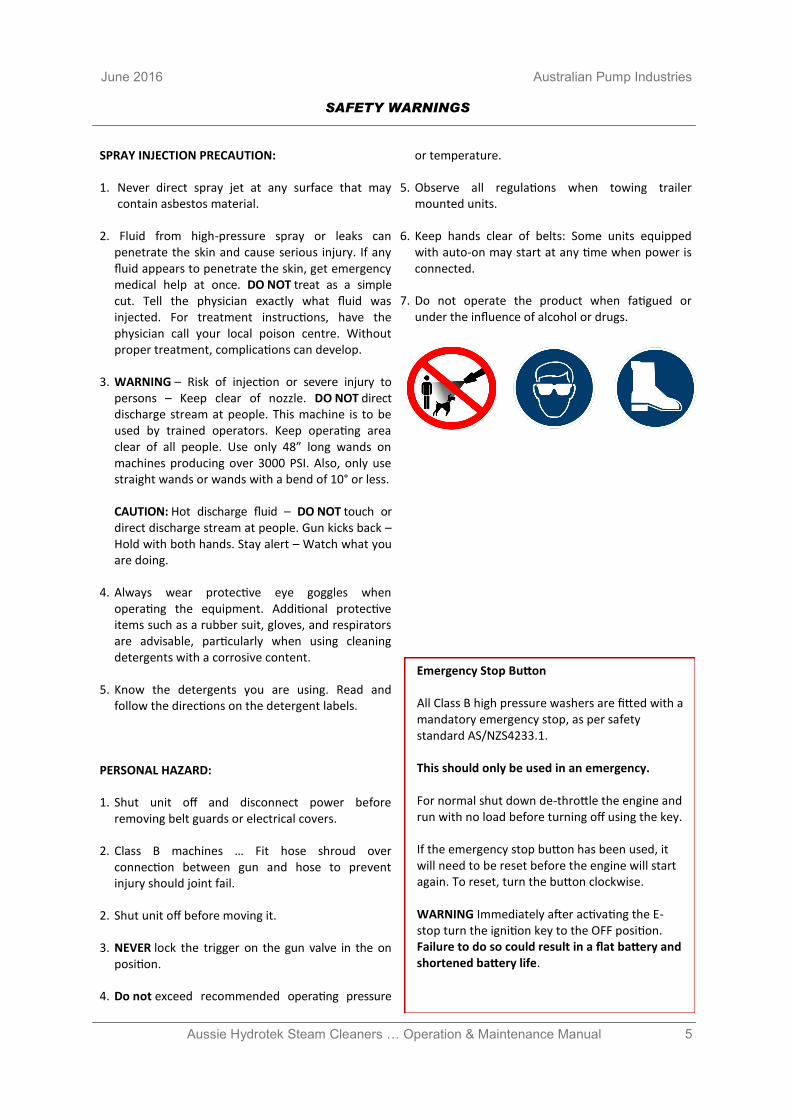
SPRAY INJECTION PRECAUTION:
1. Never direct spray jet at any surface that may contain asbestos material.
2. Fluid from high-pressure spray or leaks can penetrate the skin and cause serious injury. If any fluid appears to penetrate the skin, get emergency medical help at once. DO NOT treat as a simple cut. Tell the physician exactly what fluid was injected. For treatment instructions, have the physician call your local poison centre. Without proper treatment, complications can develop.
3. WARNING – Risk of injection or severe injury to persons – Keep clear of nozzle. DO NOT direct discharge stream at people. This machine is to be used by trained operators. Keep operating area clear of all people. Use only 48” long wands on machines producing over 3000 PSI. Also, only use straight wands or wands with a bend of 10° or less.
CAUTION: Hot discharge fluid – DO NOT touch or direct discharge stream at people. Gun kicks back – Hold with both hands. Stay alert – Watch what you are doing.
4. Always wear protective eye goggles when operating the equipment. Additional protective items such as a rubber suit, gloves, and respirators are advisable, particularly when using cleaning detergents with a corrosive content.
5. Know the detergents you are using. Read and follow the directions on the detergent labels.
PERSONAL HAZARD:
1. Shut unit off and disconnect power before removing belt guards or electrical covers.
2. Class B machines … Fit hose shroud over connection between gun and hose to prevent injury should joint fail.
2. Shut unit off before moving it.
3. NEVER lock the trigger on the gun valve in the on position.
4. Do not exceed recommended operating pressure
or temperature.
5. Observe all regulations when towing trailer mounted units.
6. Keep hands clear of belts: Some units equipped with auto-on may start at any time when power is connected.
7. Do not operate the product when fatigued or under the influence of alcohol or drugs.
SAFETY WARNINGS
Emergency Stop Button All Class B high pressure washers are fitted with a mandatory emergency stop, as per safety standard AS/NZS4233.1. This should only be used in an emergency. For normal shut down de-throttle the engine and run with no load before turning off using the key. If the emergency stop button has been used, it will need to be reset before the engine will start again. To reset, turn the button clockwise. WARNING Immediately after activating the E-stop turn the ignition key to the OFF position. Failure to do so could result in a flat battery and shortened battery life.
6 Aussie Hydrotek Steam Cleaners … Operation & Maintenance Manual
Australian Pump Industries June 2016
OPERATING INSTRUCTIONS
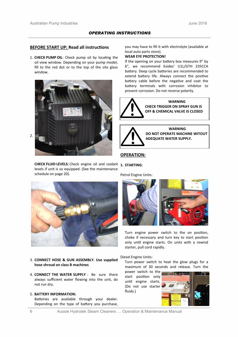
BEFORE START UP: Read all instructions 1. CHECK PUMP OIL: Check pump oil by locating the
oil view window. Depending on your pump model, fill to the red dot or to the top of the site glass window.
2.
CHECK FLUID LEVELS: Check engine oil and coolant levels if unit is so equipped. (See the maintenance schedule on page 20).
3. CONNECT HOSE & GUN ASSEMBLY. Use supplied
hose shroud on class B machines 4. CONNECT THE WATER SUPPLY : Be sure there
always sufficient water flowing into the unit, do not run dry.
5. BATTERY INFORMATION:
Batteries are available through your dealer. Depending on the type of battery you purchase,
you may have to fill it with electrolyte (available at local auto parts store). WEAR EYE PROTECTION! If the opening on your battery box measures 9” by 6”, we recommend Exides’ U1L/GTH 235CCA battery. Deep cycle batteries are recommended to extend battery life. Always connect the positive battery cable before the negative and coat the battery terminals with corrosion inhibitor to prevent corrosion. Do not reverse polarity.
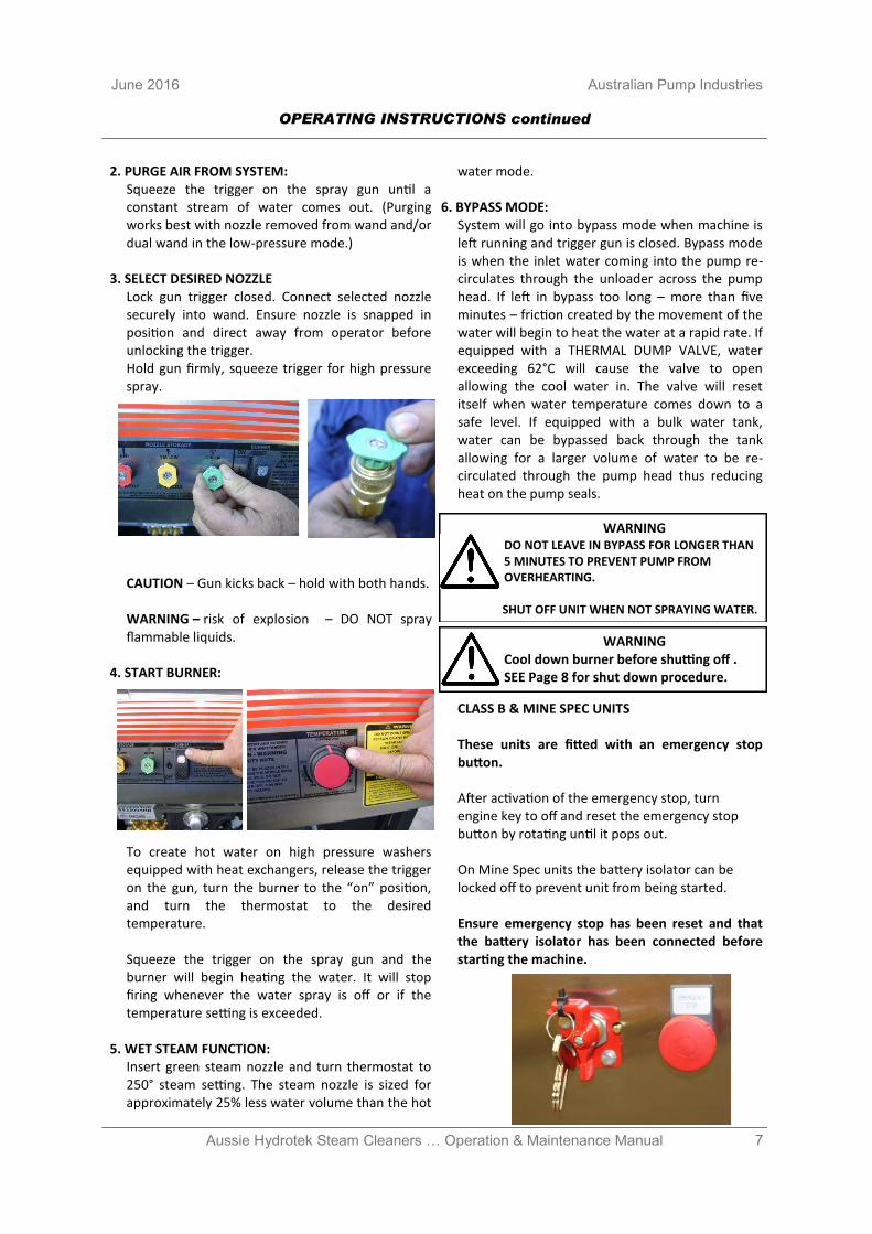
OPERATION: 1. STARTING: Petrol Engine Units:
Turn engine power switch to the on position, choke if necessary and turn key to start position only until engine starts. On units with a rewind starter, pull cord rapidly.
Diesel Engine Units: Turn power switch to heat the glow plugs for a maximum of 30 seconds and release. Turn the power switch to the start position only until engine starts. (Do not use starter fluids.)
WARNING CHECK TRIGGER ON SPRAY GUN IS OFF & CHEMICAL VALVE IS CLOSED
WARNING DO NOT OPERATE MACHINE WITOUT ADEQUATE WATER SUPPLY.
7 Aussie Hydrotek Steam Cleaners … Operation & Maintenance Manual
June 2016 Australian Pump Industries
2. PURGE AIR FROM SYSTEM: Squeeze the trigger on the spray gun until a constant stream of water comes out. (Purging works best with nozzle removed from wand and/or dual wand in the low-pressure mode.)
3. SELECT DESIRED NOZZLE Lock gun trigger closed. Connect selected nozzle securely into wand. Ensure nozzle is snapped in position and direct away from operator before unlocking the trigger. Hold gun firmly, squeeze trigger for high pressure spray.
CAUTION – Gun kicks back – hold with both hands. WARNING – risk of explosion – DO NOT spray flammable liquids.
4. START BURNER:
To create hot water on high pressure washers equipped with heat exchangers, release the trigger on the gun, turn the burner to the “on” position, and turn the thermostat to the desired temperature. Squeeze the trigger on the spray gun and the burner will begin heating the water. It will stop firing whenever the water spray is off or if the temperature setting is exceeded.
5. WET STEAM FUNCTION: Insert green steam nozzle and turn thermostat to 250° steam setting. The steam nozzle is sized for approximately 25% less water volume than the hot
water mode. 6. BYPASS MODE:
System will go into bypass mode when machine is left running and trigger gun is closed. Bypass mode is when the inlet water coming into the pump re-circulates through the unloader across the pump head. If left in bypass too long – more than five minutes – friction created by the movement of the water will begin to heat the water at a rapid rate. If equipped with a THERMAL DUMP VALVE, water exceeding 62°C will cause the valve to open allowing the cool water in. The valve will reset itself when water temperature comes down to a safe level. If equipped with a bulk water tank, water can be bypassed back through the tank allowing for a larger volume of water to be re-circulated through the pump head thus reducing heat on the pump seals.
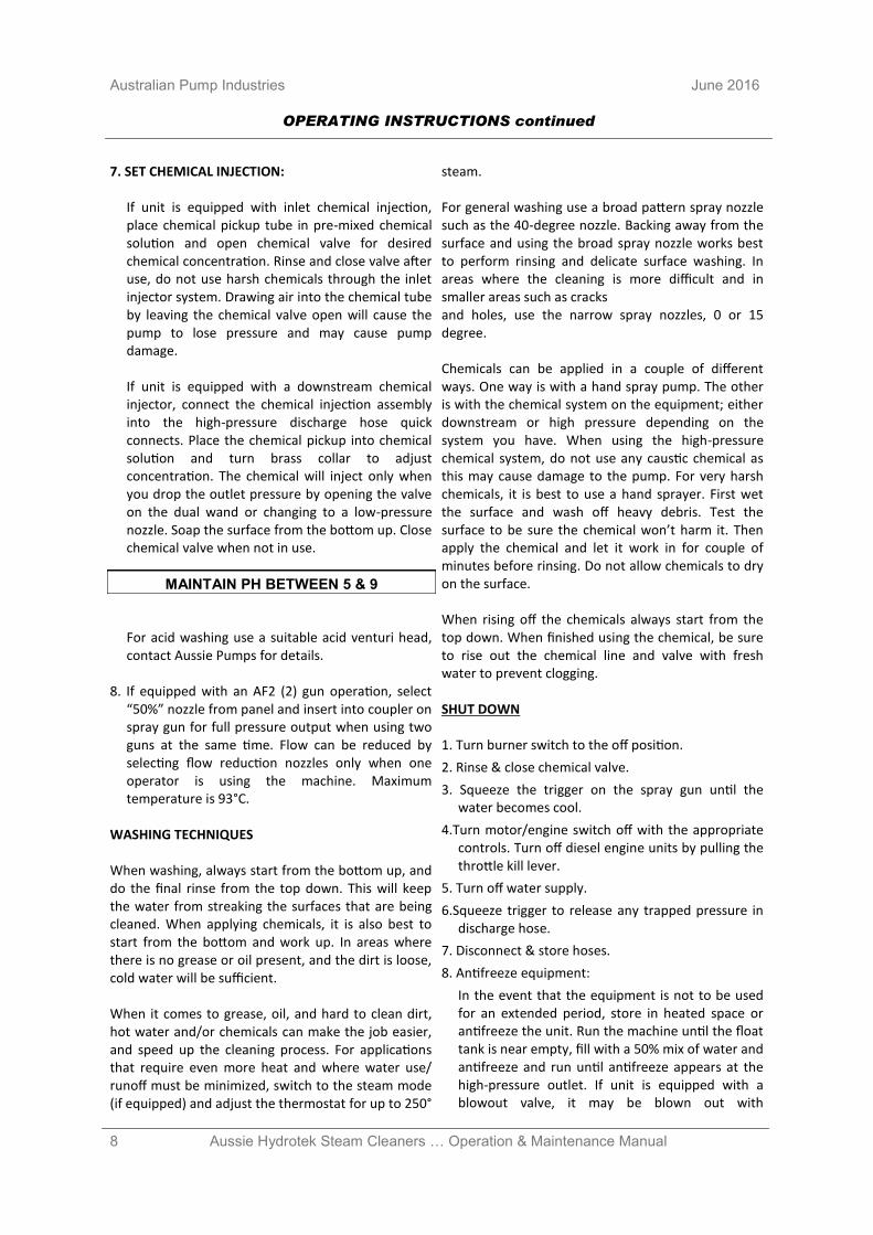
CLASS B & MINE SPEC UNITS These units are fitted with an emergency stop button. After activation of the emergency stop, turn engine key to off and reset the emergency stop button by rotating until it pops out. On Mine Spec units the battery isolator can be locked off to prevent unit from being started. Ensure emergency stop has been reset and that the battery isolator has been connected before starting the machine.
WARNING DO NOT LEAVE IN BYPASS FOR LONGER THAN 5 MINUTES TO PREVENT PUMP FROM OVERHEARTING. SHUT OFF UNIT WHEN NOT SPRAYING WATER.
WARNING Cool down burner before shutting off . SEE Page 8 for shut down procedure.
OPERATING INSTRUCTIONS continued
8 Aussie Hydrotek Steam Cleaners … Operation & Maintenance Manual
Australian Pump Industries June 2016
7. SET CHEMICAL INJECTION:
If unit is equipped with inlet chemical injection, place chemical pickup tube in pre-mixed chemical solution and open chemical valve for desired chemical concentration. Rinse and close valve after use, do not use harsh chemicals through the inlet injector system. Drawing air into the chemical tube by leaving the chemical valve open will cause the pump to lose pressure and may cause pump damage.
If unit is equipped with a downstream chemical injector, connect the chemical injection assembly into the high-pressure discharge hose quick connects. Place the chemical pickup into chemical solution and turn brass collar to adjust concentration. The chemical will inject only when you drop the outlet pressure by opening the valve on the dual wand or changing to a low-pressure nozzle. Soap the surface from the bottom up. Close chemical valve when not in use.
For acid washing use a suitable acid venturi head, contact Aussie Pumps for details.
8. If equipped with an AF2 (2) gun operation, select
“50%” nozzle from panel and insert into coupler on spray gun for full pressure output when using two guns at the same time. Flow can be reduced by selecting flow reduction nozzles only when one operator is using the machine. Maximum temperature is 93°C.
WASHING TECHNIQUES When washing, always start from the bottom up, and do the final rinse from the top down. This will keep the water from streaking the surfaces that are being cleaned. When applying chemicals, it is also best to start from the bottom and work up. In areas where there is no grease or oil present, and the dirt is loose, cold water will be sufficient. When it comes to grease, oil, and hard to clean dirt, hot water and/or chemicals can make the job easier, and speed up the cleaning process. For applications that require even more heat and where water use/runoff must be minimized, switch to the steam mode (if equipped) and adjust the thermostat for up to 250°
steam. For general washing use a broad pattern spray nozzle such as the 40-degree nozzle. Backing away from the surface and using the broad spray nozzle works best to perform rinsing and delicate surface washing. In areas where the cleaning is more difficult and in smaller areas such as cracks and holes, use the narrow spray nozzles, 0 or 15 degree. Chemicals can be applied in a couple of different ways. One way is with a hand spray pump. The other is with the chemical system on the equipment; either downstream or high pressure depending on the system you have. When using the high-pressure chemical system, do not use any caustic chemical as this may cause damage to the pump. For very harsh chemicals, it is best to use a hand sprayer. First wet the surface and wash off heavy debris. Test the surface to be sure the chemical won’t harm it. Then apply the chemical and let it work in for couple of minutes before rinsing. Do not allow chemicals to dry on the surface. When rising off the chemicals always start from the top down. When finished using the chemical, be sure to rise out the chemical line and valve with fresh water to prevent clogging. SHUT DOWN 1. Turn burner switch to the off position.
2. Rinse & close chemical valve.
3. Squeeze the trigger on the spray gun until the water becomes cool.
4.Turn motor/engine switch off with the appropriate controls. Turn off diesel engine units by pulling the throttle kill lever.
5. Turn off water supply.
6.Squeeze trigger to release any trapped pressure in discharge hose.
7. Disconnect & store hoses.
8. Antifreeze equipment:
In the event that the equipment is not to be used for an extended period, store in heated space or antifreeze the unit. Run the machine until the float tank is near empty, fill with a 50% mix of water and antifreeze and run until antifreeze appears at the high-pressure outlet. If unit is equipped with a blowout valve, it may be blown out with
OPERATING INSTRUCTIONS continued
MAINTAIN PH BETWEEN 5 & 9
9 Aussie Hydrotek Steam Cleaners … Operation & Maintenance Manual
June 2016 Australian Pump Industries
compressed air in addition to using antifreeze solution.
On direct feed units (no float tank), use a 5’ garden hose to draw the antifreeze mix from a bucket or blow out the unit with compressed air until only air and no water comes out of the discharge.
APPEARANCE: To maintain appearance of the power washer, use stainless steel cleaner on the stainless steel panels. Do not pressure wash your Aussie Hydrotek. POWER SYSTEMS: PETROL ENGINE: With the proper care and maintenance, your PETROL engine will give years of trouble free service. Please follow the Service and Maintenance Guide and the enclosed engine sheet or contact your local authorized engine dealer for maintenance and repairs. Use unleaded PETROL with an octane rating of 87 or higher in the engine fuel tank. Consult engine manual for proper oil type and capacity. The engine manufacturer recommends a break-in period of 25 hours at which time the engine oil and filter should be replaced. Thereafter, change oil every 50 hours and the filter every 100 hours (see engine manual). Do not rely on the low oil shutdown (if equipped) as a reminder to add oil. The engine manufacturer will typically not warranty engine damage from lack of oil even if the low oil system failed. On machines with a 115V generator or a 12V burner, the throttle is preset at the factory (See Generator section). Engines include backfire prevention solenoids. DIESEL ENGINE: The diesel engine, although it has a higher initial cost, can save money with lower fuel consumption and longer life. Use clean diesel fuel and do not allow engine to run out of fuel or the system will have to be bled to restart the engine. Clean the fuel filter periodically with kerosene (See Engine Manual). Use 10w – 30 oil with API classification CC/CD grade rated for diesel engines in the engine crankcase and change every 50 hours. If the engine is water cooled, use a 50/50 mix of antifreeze/de-ionized water solution and check daily. Never use more antifreeze than water or damage to the engine could occur from overheating.
POWER TRANSMISSION: WARNING: Shut off power. BELT DRIVE: Check belt condition, alignment and tension periodically. Replace belts when they show signs of wear or cracking. Tighten belts by loosening the mounting bolts on the pump and generator to permit them to slide. Turn the horizontal rail adjusting bolts to tighten belts until they deflect ¼ “ to ½” with finger pressure. DIRECT DRIVE: Pump is bolted directly to the motor/engine. If pump needs to be removed, do not force off by prying or damage may occur. When reassembling, coat the entire motor shaft with heavy grease, or a generous amount of anti-seize and use “thread locker” or “lock tight” on mounting bolts. GENERATOR: Some self-contained hot water units (SC and SCU Series) are equipped with a 115v, 2900w generator to power the diesel burner. The generator output voltage must be between 110 to 130 Volts, (or between 59 to 63 Hz.), when the unit is under full load. If the generator voltage falls out of this range, the RPM of the engine will need to be adjusted to proper speed. If the engine cannot maintain the proper RPM, do not use the burner or any power from the generator until the engine is repaired. An AUXILIARY OUTLET is available on some SC or SCU Series machines for running wastewater recovery systems, light, or other accessories off of the generator. A maximum of 1500 watts of 115v power is available when the burner is on or 2000 watts when it is off. A switch/circuit breaker located on the control panel will need to be reset if the circuit is overloaded. Use of a ground fault interrupter is recommended when plugging in accessories or lights to the auxiliary voltage outlet. To extend generator life, make sure the burner and all auxiliary power is off when the engine is started or stopped. Keep generator dry. PUMPING SYSTEM: PUMP: The pump is a positive displacement, oil bath crankcase, and triplex plunger type. It contains 3 plungers, which move forward and backward in a cylinder to propel water past 3 inlet valves and 3 discharge valves into a high-pressure manifold. The crank case oil window should be checked for oil level and clarity and the pump for oil or water leaks before
SYSTEM INFORMATION
10 Aussie Hydrotek Steam Cleaners … Operation & Maintenance Manual
Australian Pump Industries June 2016
each use. The sight window is located at the rear (opposite the head) of the pump and should be filled to the red dot with non-detergent 30w pump oil, available at your Aussie Hydrotek dealer. If the oil becomes milky in color, moisture is entering the crankcase. Change the oil and contact your authorized Aussie Hydrotek dealer if the problem persists. Keeping filters clean and checking for air in pump feed lines can prevent cavitation and increase pump life. Do not run pump in the bypass mode (pump running with the trigger gun off), for a period of more than 5 minutes or the pump will begin to overheat (maximum water temperature is 62°C). Do not run pump dry. Protect from freezing. Do not run a frozen pump until it is completely thawed. UNLOADER AND PRESSURE RELIEF VALVE: The unloader valve is preset at the factory to govern the proper output pressure of your machine. It will release the pressure of the pump back into the inlet if the trigger on the spray gun is released. NEVER increase the set pressure on the unloader to exceed the specifications for your machine. All hot water machines are equipped with a SAFETY PRESSURE RELIEF VALVE. In the unlikely event that your unloader fails, or if the burner overheats and builds excessive pressure, the pressure relief valve will vent the pressure into the atmosphere. If this occurs, turn off the machine and have it checked by an authorized dealer. The pressure relief valve will automatically reset itself. BURST DISC TECHNOLOGY: This additional safety feature functions to protect the coil from the heating system and high system spikes of pressure. If this component ruptures, you should take the machine in to an authorized Aussie Hydrotek dealer. Do not plug off and continue to run. CHEMICAL INJECTION SYSTEM: With an inlet chemical injection system, the chemicals are introduced at the inlet of the pump and controlled with a chemical metering valve. The pump is fed by a float tank to create a light vacuum, not to exceed negative 3psi, which draws up the chemical into the inlet manifold of the pump, mixes it with water, and sprays it out of the nozzle under high pressure. Open the chemical valve only when the pickup tube is submersed in a solution or air will enter the pump causing the pump to lose pressure and run rough. Do not use highly
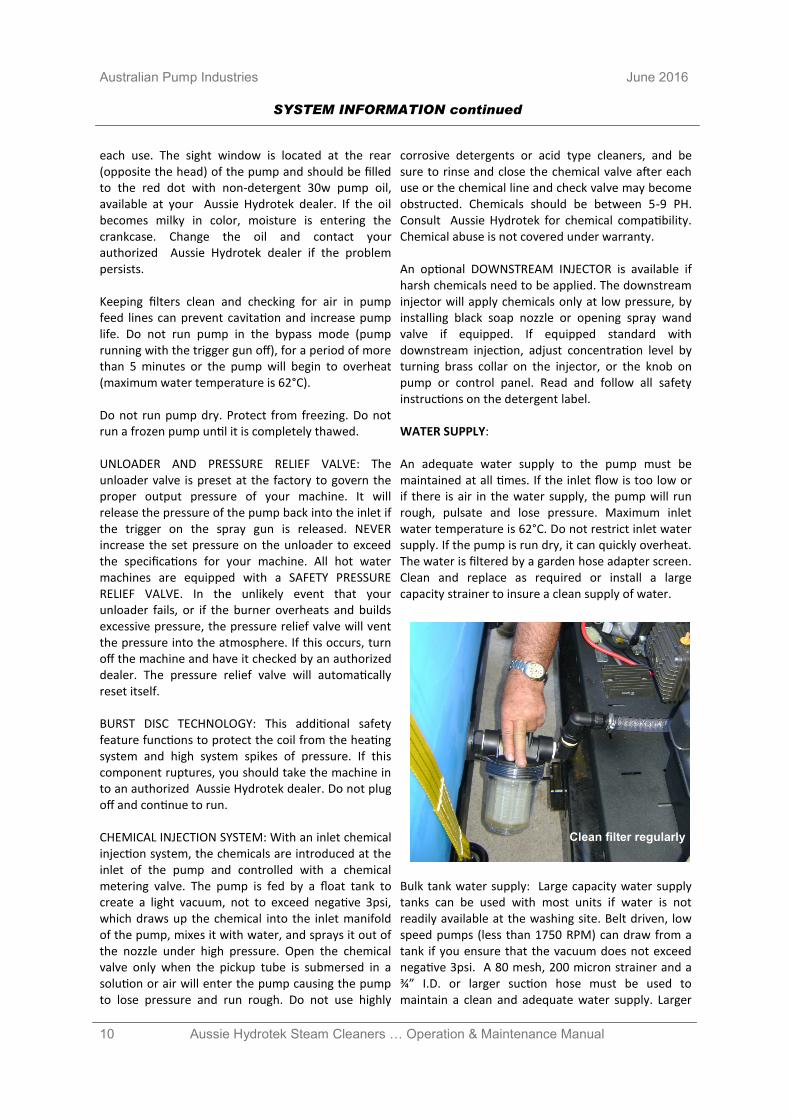
corrosive detergents or acid type cleaners, and be sure to rinse and close the chemical valve after each use or the chemical line and check valve may become obstructed. Chemicals should be between 5-9 PH. Consult Aussie Hydrotek for chemical compatibility. Chemical abuse is not covered under warranty. An optional DOWNSTREAM INJECTOR is available if harsh chemicals need to be applied. The downstream injector will apply chemicals only at low pressure, by installing black soap nozzle or opening spray wand valve if equipped. If equipped standard with downstream injection, adjust concentration level by turning brass collar on the injector, or the knob on pump or control panel. Read and follow all safety instructions on the detergent label. WATER SUPPLY: An adequate water supply to the pump must be maintained at all times. If the inlet flow is too low or if there is air in the water supply, the pump will run rough, pulsate and lose pressure. Maximum inlet water temperature is 62°C. Do not restrict inlet water supply. If the pump is run dry, it can quickly overheat. The water is filtered by a garden hose adapter screen. Clean and replace as required or install a large capacity strainer to insure a clean supply of water.
Bulk tank water supply: Large capacity water supply tanks can be used with most units if water is not readily available at the washing site. Belt driven, low speed pumps (less than 1750 RPM) can draw from a tank if you ensure that the vacuum does not exceed negative 3psi. A 80 mesh, 200 micron strainer and a ¾” I.D. or larger suction hose must be used to maintain a clean and adequate water supply. Larger
SYSTEM INFORMATION continued
Clean filter regularly
11 Aussie Hydrotek Steam Cleaners … Operation & Maintenance Manual
June 2016 Australian Pump Industries
flow (8-10gpm) machines require 1” feed and filtration. Be sure that the water supply is free from air or damage to the pump may result. Periodically you should clean out the strainer and water supply tank to remove debris that may accumulate on the bottom. If a water supply tank and a float tank are both utilized, a special three way valve can be used to switch between tanks. USING DE-IONIZED OR SOFTENED WATER IN YOUR POWER WASHER: Do not use de-ionized water through the coil on a hot water machine or coil corrosion will result. Water softeners, however, will reduce coil scale deposits and should be installed if your water is especially hard. HEATING SYSTEM: COIL/HEAT EXCHANGER SYSTEM: The heat exchanger contains a continuous coil of pipe, which forms a cold water jacket around the outside of the heating area. It is double wrapped with ceramic blanket insulation and a stainless steel cover. The inside of the coil assembly can become covered with soot if the burner is out of adjustment or if it is fired by diesel fuel. This can be cleaned by removing both end caps on the coil enclosure and brushing or spraying off debris, or by adding a soot removal agent (Part #CB200) to the diesel fuel. Both a diesel fuel pressure gauge and smoke test device is required for proper burner adjustment, and must be performed by a qualified technician. When the water is heated, scale (calcium) will begin to form on the inside of the coil pipe depending upon the hardness of the water in your area. To remove build-up in the coil, use a scale remover (Part #CB100) available at your authorized Aussie Hydrotek dealer. Perform this descaling service only when a noticeable pressure drop is detected across the coil. Follow directions to avoid damage. Wear safety glasses. TEMPERATURE SWITCH: The burner is equipped with a high temperature limit switch, which will shut off the burner when the water temperature becomes too hot. Hot water machines are equipped with an adjustable thermostat so that the operator can control the outlet water temperature. The burner will automatically cycle on and off to maintain the desired temperature.
STEAM INSTRUCTIONS: If your unit is steam capable, install the green steam nozzle, turn thermostat to 250° F. PRESSURE/FLOW SWITCH: The burner is equipped with either a pressure switch or a flow switch to control the burner. When the trigger on the spray gun is squeezed, water begins to move through the coil and pressurize. The flow/pressure switch turns the burner on and begins to heat the water. Whenever the water spray stops or if the water is shut off, the burner will shut off. WARNING: Burner should fire only when the trigger is squeezed and spraying water, if it comes on at any other time, shut off machine and have it serviced. DIAGNOSTIC LIGHT: The burner diagnostic light on the rocker switch (if equipped) can help in determining problems with the burner. The red light indicates that power is going to the fuel solenoid valve. The burner should be firing and heating the water whenever the red light is on. When the trigger on the spray gun is released or if the temperature set point is exceeded, the red light will go off and the burner will stop firing. SYSTEM INFORMATION 9 DIESEL FIRED BURNER: The diesel-fired burner is a forced draft pressure-atomizing burner. Diesel fuel is sprayed out of an atomizing nozzle, mixed with air, and ignited by a high voltage spark. The flame is directed towards the coils of pipe, which in turn, heats the water flowing through it. Use clean DIESEL FUEL for the burner. AIR BAND adjustments may need to be made to compensate for higher elevations, or if more than a trace of smoke is observed in the burner exhaust. The ELECTRODES may need to be cleaned and adjusted periodically. These adjustments have to be made precisely and should be performed only by qualified personnel. Set between #1 & #2 on the smoke gauge. The FUEL PUMP is a self priming, low volume pump which is propelled by the burner motor. The fuel pump pressure is typically set at 100 PSI but can be turned as high as 140 PSI during the winter when the incoming water temperature is lower. Before adjusting the fuel pressure, connect a fuel pressure gauge and an outlet water temperature gauge, turn the pump and burner on, and turn the fuel pressure screw clockwise until the desired water temperature is obtained. Be sure not to exceed the commended specifications of the machine.
SYSTEM INFORMATION continued
12 Aussie Hydrotek Steam Cleaners … Operation & Maintenance Manual
Australian Pump Industries June 2016
The FUEL FILTER will need to be replaced often if the diesel fuel quality is poor. A fuel filter with a water separator is recommended if the fuel quality is consistently poor. The FUEL SOLENOID is an electric fuel valve that shuts off the fuel whenever the trigger on the spray gun is released or if the set temperature on the heat switch is exceeded. The IGNITION TRANSFORMER provides a high voltage spark that travels down the electrodes to ignite the diesel fuel. Disconnect all power before servicing. The 12V burner operates from the battery on the SS Series (and a limited number of SC Series). The engine has a 15 to 20 amp charging system that keeps the battery charged which runs the burner. The burner motor and transformer stop when the trigger gun is released and is controlled through a high amperage contactor. To help keep the battery fully charged, and for safely cooling down the burner, turn off the burner during the last minute of rinsing. When leaving the machine unattended, shut off burner and engine switch. Replace 12 VDC battery regularly (2 year maximum interval) on 12V burner systems to help ensure consistent performance. PRESSURE DELIVERY STYSTEM: DISCHARGE HOSE: Use only a wire braid hose rated for the output pressure and temperature of the machine. Single wire braid hoses are generally rated from 2500 to 4000psi. Additional hose lengths can be added with quick twist couplers with a minimal loss in pressure of about .5 PSI per foot. Inspect hoses for wear and replace if necessary. Avoid kinking or running over the hose to extend the hose life. WARNING: Aussie Hydrotek hot water machines require a special 120°C rated hose to operate in the steam mode. If the hose is not replaced when worn or if it is not replaced by a Aussie Hydrotek original equipment hose, it may burst and serious injury and burns could result.
QUICK COUPLERS: The swivel connectors on the high-pressure hose and quick couplers on the spray nozzle make it easy to change nozzles or hoses. When connecting hoses or nozzles, be certain that the collar on the quick couplers snap into the locked position to prevent them from becoming loose. If the quick connect begins to leak, replace the O-ring (specify Viton or EDPM material) located in the female socket coupler. Grease the coupler periodically to make it work smoothly. Replace if it becomes worn. Twist couplers are also used on most wands so they can be interchanged. TRIGGER GUNS: The trigger gun is merely a valve that turns water spray on and off. If it begins to leak or fails to shut off, replace or repair the valve assembly. Never lock any gun in the on position for any reason. Never point spray at a person or any part of the body. SPRAY WAND: Wands are available in 2 to 6 foot lengths for various cleaning applications. If the unit is equipped with a dual wand, you can adjust the pressure by turning the knob on the valve to divert part of the water through the low-pressure nozzle.
SYSTEM INFORMATION continued
13 Aussie Hydrotek Steam Cleaners … Operation & Maintenance Manual
June 2016 Australian Pump Industries
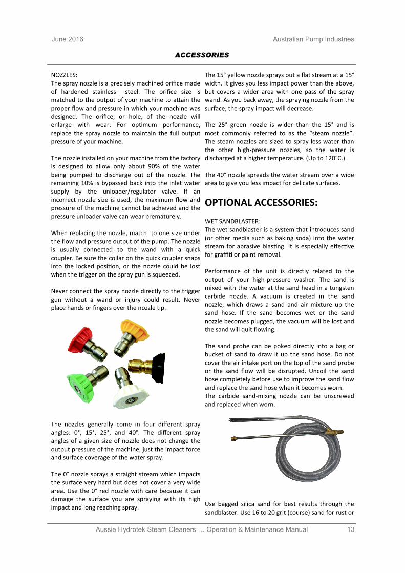
NOZZLES: The spray nozzle is a precisely machined orifice made of hardened stainless steel. The orifice size is matched to the output of your machine to attain the proper flow and pressure in which your machine was designed. The orifice, or hole, of the nozzle will enlarge with wear. For optimum performance, replace the spray nozzle to maintain the full output pressure of your machine. The nozzle installed on your machine from the factory is designed to allow only about 90% of the water being pumped to discharge out of the nozzle. The remaining 10% is bypassed back into the inlet water supply by the unloader/regulator valve. If an incorrect nozzle size is used, the maximum flow and pressure of the machine cannot be achieved and the pressure unloader valve can wear prematurely. When replacing the nozzle, match to one size under the flow and pressure output of the pump. The nozzle is usually connected to the wand with a quick coupler. Be sure the collar on the quick coupler snaps into the locked position, or the nozzle could be lost when the trigger on the spray gun is squeezed. Never connect the spray nozzle directly to the trigger gun without a wand or injury could result. Never place hands or fingers over the nozzle tip.
The nozzles generally come in four different spray angles: 0°, 15°, 25°, and 40°. The different spray angles of a given size of nozzle does not change the output pressure of the machine, just the impact force and surface coverage of the water spray. The 0° nozzle sprays a straight stream which impacts the surface very hard but does not cover a very wide area. Use the 0° red nozzle with care because it can damage the surface you are spraying with its high impact and long reaching spray.
The 15° yellow nozzle sprays out a flat stream at a 15° width. It gives you less impact power than the above, but covers a wider area with one pass of the spray wand. As you back away, the spraying nozzle from the surface, the spray impact will decrease. The 25° green nozzle is wider than the 15° and is most commonly referred to as the “steam nozzle”. The steam nozzles are sized to spray less water than the other high-pressure nozzles, so the water is discharged at a higher temperature. (Up to 120°C.) The 40° nozzle spreads the water stream over a wide area to give you less impact for delicate surfaces.
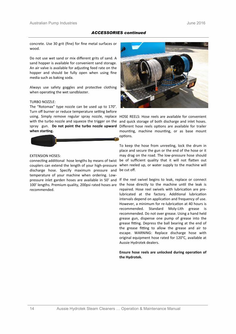
OPTIONAL ACCESSORIES: WET SANDBLASTER: The wet sandblaster is a system that introduces sand (or other media such as baking soda) into the water stream for abrasive blasting. It is especially effective for graffiti or paint removal. Performance of the unit is directly related to the output of your high-pressure washer. The sand is mixed with the water at the sand head in a tungsten carbide nozzle. A vacuum is created in the sand nozzle, which draws a sand and air mixture up the sand hose. If the sand becomes wet or the sand nozzle becomes plugged, the vacuum will be lost and the sand will quit flowing. The sand probe can be poked directly into a bag or bucket of sand to draw it up the sand hose. Do not cover the air intake port on the top of the sand probe or the sand flow will be disrupted. Uncoil the sand hose completely before use to improve the sand flow and replace the sand hose when it becomes worn. The carbide sand-mixing nozzle can be unscrewed and replaced when worn.
Use bagged silica sand for best results through the sandblaster. Use 16 to 20 grit (course) sand for rust or
ACCESSORIES
14 Aussie Hydrotek Steam Cleaners … Operation & Maintenance Manual
Australian Pump Industries June 2016
concrete. Use 30 grit (fine) for fine metal surfaces or wood. Do not use wet sand or mix different grits of sand. A sand hopper is available for convenient sand storage. An air valve is available for adjusting feed rate on the hopper and should be fully open when using fine media such as baking soda. Always use safety goggles and protective clothing when operating the wet sandblaster. TURBO NOZZLE: The “Rotomax” type nozzle can be used up to 170°. Turn off burner or reduce temperature setting before using. Simply remove regular spray nozzle, replace with the turbo nozzle and squeeze the trigger on the spray gun. Do not point the turbo nozzle upward when starting.
EXTENSION HOSES: connecting additional hose lengths by means of twist couplers can extend the length of your high-pressure discharge hose. Specify maximum pressure and temperature of your machine when ordering. Low-pressure inlet garden hoses are available in 50’ and 100’ lengths. Premium quality, 200psi rated hoses are recommended.
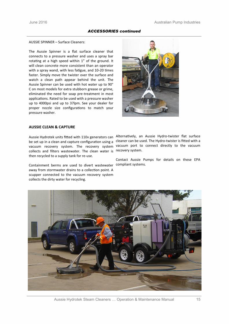
HOSE REELS: Hose reels are available for convenient and quick storage of both discharge and inlet hoses. Different hose reels options are available for trailer mounting, machine mounting, or as base mount options. To keep the hose from unreeling, lock the drum in place and secure the gun or the end of the hose or it may drag on the road. The low-pressure hose should be of sufficient quality that it will not flatten out when reeled up, or water supply to the machine will be cut off. If the reel swivel begins to leak, replace or connect the hose directly to the machine until the leak is repaired. Hose reel swivels with lubrication are pre-lubricated at the factory. Additional lubrication intervals depend on application and frequency of use. However, a minimum for re-lubrication at 40 hours is recommended. Standard Moly-Lith grease is recommended. Do not over grease. Using a hand held grease gun, dispense one pump of grease into the grease fitting. Depress the ball bearing at the end of the grease fitting to allow the grease and air to escape. WARNING: Replace discharge hose with original equipment hose rated for 120°C, available at Aussie Hydrotek dealers. Ensure hose reels are unlocked during operation of the Hydrotek.
ACCESSORIES continued
15 Aussie Hydrotek Steam Cleaners … Operation & Maintenance Manual
June 2016 Australian Pump Industries
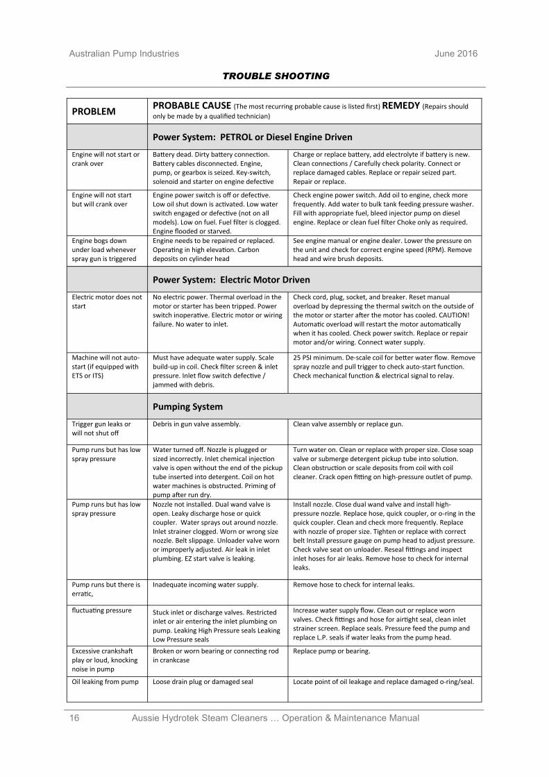
AUSSIE SPINNER – Surface Cleaners: The Aussie Spinner is a flat surface cleaner that connects to a pressure washer and uses a spray bar rotating at a high speed within 1” of the ground. It will clean concrete more consistent than an operator with a spray wand, with less fatigue, and 10-20 times faster. Simply move the twister over the surface and watch a clean path appear behind the unit. The Aussie Spinner can be used with hot water up to 90° C on most models for extra stubborn grease or grime, eliminated the need for soap pre-treatment in most applications. Rated to be used with a pressure washer up to 4000psi and up to 37lpm. See your dealer for proper nozzle size configurations to match your pressure washer.
AUSSIE CLEAN & CAPTURE Aussie Hydrotek units fitted with 110v generators can be set up in a clean and capture configuration using a vacuum recovery system. The recovery system collects and filters wastewater. The clean water is then recycled to a supply tank for re-use. Containment berms are used to divert wastewater away from stormwater drains to a collection point. A scupper connected to the vacuum recovery system collects the dirty water for recycling.
Alternatively, an Aussie Hydro-twister flat surface cleaner can be used. The Hydro-twister is fitted with a vacuum port to connect directly to the vacuum recovery system. Contact Aussie Pumps for details on these EPA compliant systems.
ACCESSORIES continued
16 Aussie Hydrotek Steam Cleaners … Operation & Maintenance Manual
Australian Pump Industries June 2016
PROBLEM PROBABLE CAUSE (The most recurring probable cause is listed first) REMEDY (Repairs should
only be made by a qualified technician)
Power System: PETROL or Diesel Engine Driven
Engine will not start or crank over
Battery dead. Dirty battery connection. Battery cables disconnected. Engine, pump, or gearbox is seized. Key-switch, solenoid and starter on engine defective
Charge or replace battery, add electrolyte if battery is new. Clean connections / Carefully check polarity. Connect or replace damaged cables. Replace or repair seized part. Repair or replace.
Engine will not start but will crank over
Engine power switch is off or defective. Low oil shut down is activated. Low water switch engaged or defective (not on all models). Low on fuel. Fuel filter is clogged. Engine flooded or starved.
Check engine power switch. Add oil to engine, check more frequently. Add water to bulk tank feeding pressure washer. Fill with appropriate fuel, bleed injector pump on diesel engine. Replace or clean fuel filter Choke only as required.
Engine bogs down under load whenever spray gun is triggered
Engine needs to be repaired or replaced. Operating in high elevation. Carbon deposits on cylinder head
See engine manual or engine dealer. Lower the pressure on the unit and check for correct engine speed (RPM). Remove head and wire brush deposits.
Power System: Electric Motor Driven
Electric motor does not start
No electric power. Thermal overload in the motor or starter has been tripped. Power switch inoperative. Electric motor or wiring failure. No water to inlet.
Check cord, plug, socket, and breaker. Reset manual overload by depressing the thermal switch on the outside of the motor or starter after the motor has cooled. CAUTION! Automatic overload will restart the motor automatically when it has cooled. Check power switch. Replace or repair motor and/or wiring. Connect water supply.
Machine will not auto-start (if equipped with ETS or ITS)
Must have adequate water supply. Scale build-up in coil. Check filter screen & inlet pressure. Inlet flow switch defective / jammed with debris.
25 PSI minimum. De-scale coil for better water flow. Remove spray nozzle and pull trigger to check auto-start function. Check mechanical function & electrical signal to relay.
Pumping System
Trigger gun leaks or will not shut off
Debris in gun valve assembly. Clean valve assembly or replace gun.
Pump runs but has low spray pressure
Water turned off. Nozzle is plugged or sized incorrectly. Inlet chemical injection valve is open without the end of the pickup tube inserted into detergent. Coil on hot water machines is obstructed. Priming of pump after run dry.
Turn water on. Clean or replace with proper size. Close soap valve or submerge detergent pickup tube into solution. Clean obstruction or scale deposits from coil with coil cleaner. Crack open fitting on high-pressure outlet of pump.
Pump runs but has low spray pressure
Nozzle not installed. Dual wand valve is open. Leaky discharge hose or quick coupler. Water sprays out around nozzle. Inlet strainer clogged. Worn or wrong size nozzle. Belt slippage. Unloader valve worn or improperly adjusted. Air leak in inlet plumbing. EZ start valve is leaking.
Install nozzle. Close dual wand valve and install high-pressure nozzle. Replace hose, quick coupler, or o-ring in the quick coupler. Clean and check more frequently. Replace with nozzle of proper size. Tighten or replace with correct belt Install pressure gauge on pump head to adjust pressure. Check valve seat on unloader. Reseal fittings and inspect inlet hoses for air leaks. Remove hose to check for internal leaks.
Pump runs but there is erratic,
Inadequate incoming water supply. Remove hose to check for internal leaks.
fluctuating pressure Stuck inlet or discharge valves. Restricted inlet or air entering the inlet plumbing on pump. Leaking High Pressure seals Leaking Low Pressure seals
Increase water supply flow. Clean out or replace worn valves. Check fittings and hose for airtight seal, clean inlet strainer screen. Replace seals. Pressure feed the pump and replace L.P. seals if water leaks from the pump head.
Excessive crankshaft play or loud, knocking noise in pump
Broken or worn bearing or connecting rod in crankcase
Replace pump or bearing.
Oil leaking from pump Loose drain plug or damaged seal Locate point of oil leakage and replace damaged o-ring/seal.
TROUBLE SHOOTING
17 Aussie Hydrotek Steam Cleaners … Operation & Maintenance Manual
June 2016 Australian Pump Industries
PROBLEM
PROBABLE CAUSE (The most recurring probable cause is listed first) REMEDY (Repairs should
only be made by a qualified technician)
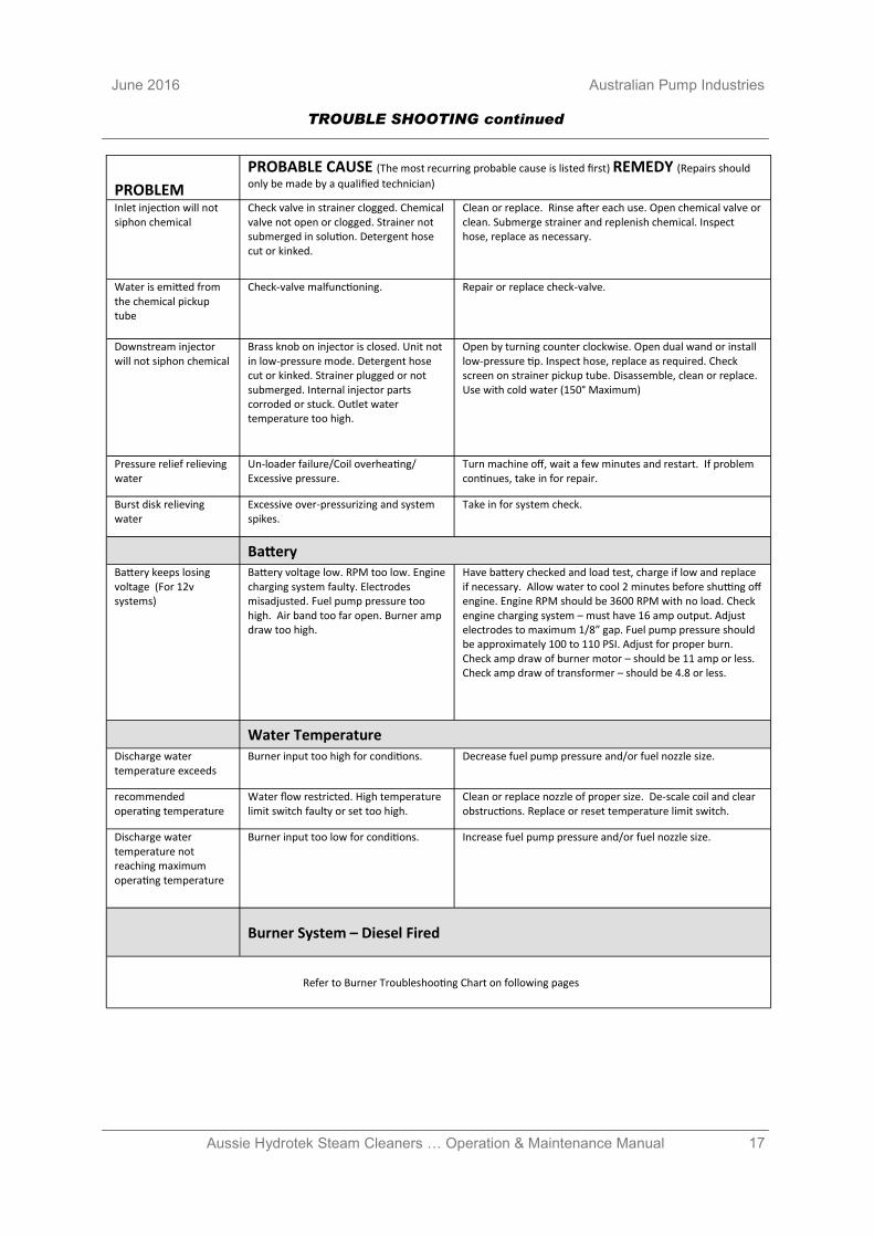
Inlet injection will not siphon chemical
Check valve in strainer clogged. Chemical valve not open or clogged. Strainer not submerged in solution. Detergent hose cut or kinked.
Clean or replace. Rinse after each use. Open chemical valve or clean. Submerge strainer and replenish chemical. Inspect hose, replace as necessary.
Water is emitted from the chemical pickup tube
Check-valve malfunctioning. Repair or replace check-valve.
Downstream injector will not siphon chemical
Brass knob on injector is closed. Unit not in low-pressure mode. Detergent hose cut or kinked. Strainer plugged or not submerged. Internal injector parts corroded or stuck. Outlet water temperature too high.
Open by turning counter clockwise. Open dual wand or install low-pressure tip. Inspect hose, replace as required. Check screen on strainer pickup tube. Disassemble, clean or replace. Use with cold water (150° Maximum)
Pressure relief relieving water
Un-loader failure/Coil overheating/Excessive pressure.
Turn machine off, wait a few minutes and restart. If problem continues, take in for repair.
Burst disk relieving water
Excessive over-pressurizing and system spikes.
Take in for system check.
Battery Battery keeps losing voltage (For 12v systems)
Battery voltage low. RPM too low. Engine charging system faulty. Electrodes misadjusted. Fuel pump pressure too high. Air band too far open. Burner amp draw too high.
Have battery checked and load test, charge if low and replace if necessary. Allow water to cool 2 minutes before shutting off engine. Engine RPM should be 3600 RPM with no load. Check engine charging system – must have 16 amp output. Adjust electrodes to maximum 1/8” gap. Fuel pump pressure should be approximately 100 to 110 PSI. Adjust for proper burn. Check amp draw of burner motor – should be 11 amp or less. Check amp draw of transformer – should be 4.8 or less.
Water Temperature Discharge water temperature exceeds
Burner input too high for conditions. Decrease fuel pump pressure and/or fuel nozzle size.
recommended operating temperature
Water flow restricted. High temperature limit switch faulty or set too high.
Clean or replace nozzle of proper size. De-scale coil and clear obstructions. Replace or reset temperature limit switch.
Discharge water temperature not reaching maximum operating temperature
Burner input too low for conditions. Increase fuel pump pressure and/or fuel nozzle size.
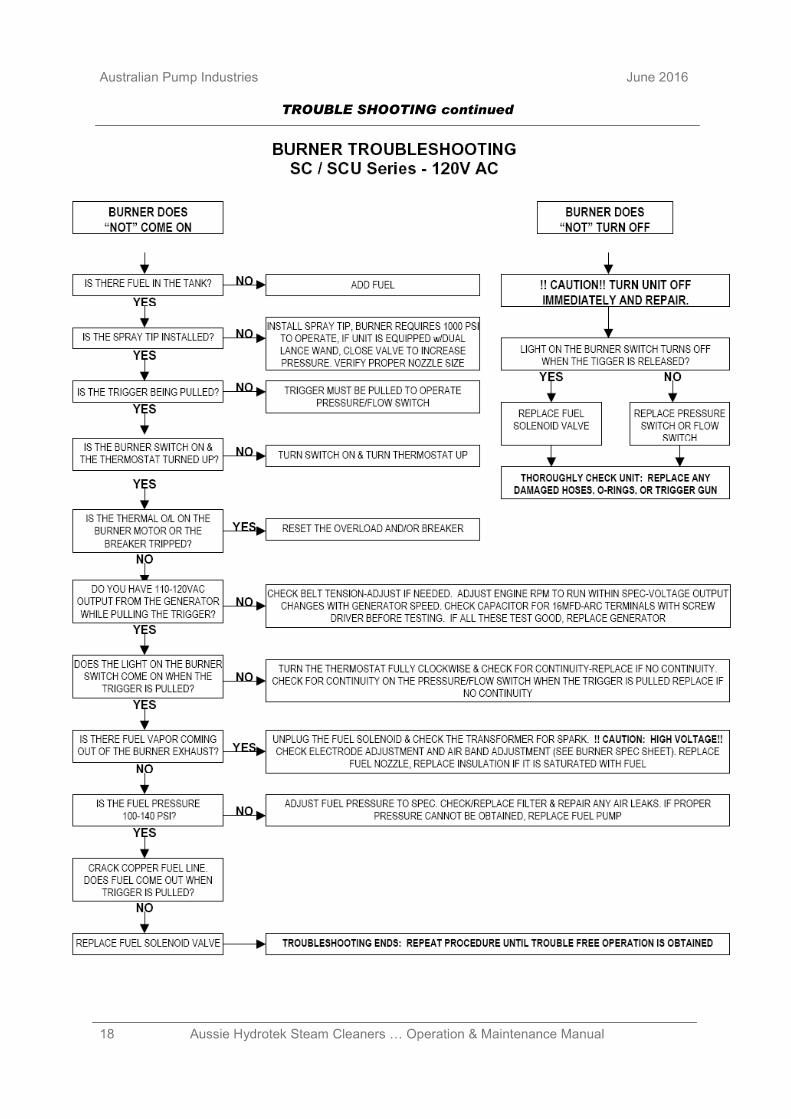
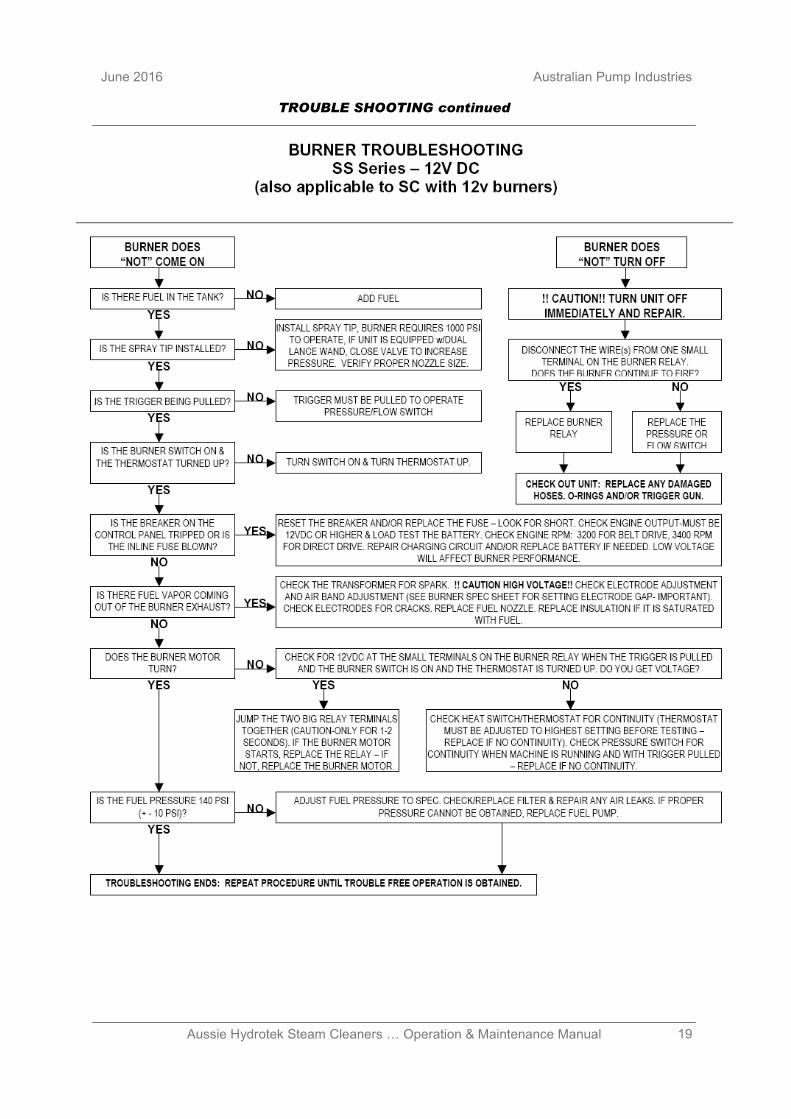
Burner System – Diesel Fired
Refer to Burner Troubleshooting Chart on following pages
TROUBLE SHOOTING continued
18 Aussie Hydrotek Steam Cleaners … Operation & Maintenance Manual
Australian Pump Industries June 2016
TROUBLE SHOOTING continued
19 Aussie Hydrotek Steam Cleaners … Operation & Maintenance Manual
June 2016 Australian Pump Industries
TROUBLE SHOOTING continued
20 Aussie Hydrotek Steam Cleaners … Operation & Maintenance Manual
Australian Pump Industries June 2016
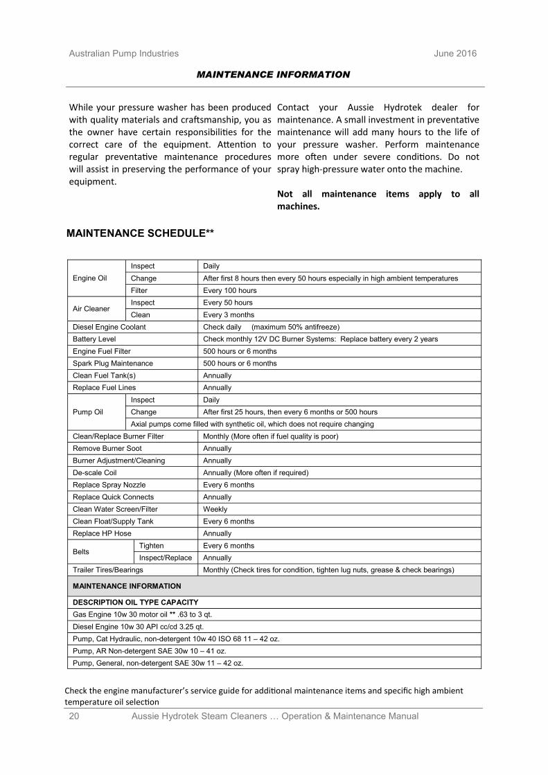
While your pressure washer has been produced with quality materials and craftsmanship, you as the owner have certain responsibilities for the correct care of the equipment. Attention to regular preventative maintenance procedures will assist in preserving the performance of your equipment.
Contact your Aussie Hydrotek dealer for maintenance. A small investment in preventative maintenance will add many hours to the life of your pressure washer. Perform maintenance more often under severe conditions. Do not spray high-pressure water onto the machine. Not all maintenance items apply to all machines.
Check the engine manufacturer’s service guide for additional maintenance items and specific high ambient temperature oil selection
Engine Oil
Inspect Daily
Change After first 8 hours then every 50 hours especially in high ambient temperatures
Filter Every 100 hours
Air Cleaner Inspect Every 50 hours
Clean Every 3 months
Diesel Engine Coolant Check daily (maximum 50% antifreeze)
Battery Level Check monthly 12V DC Burner Systems: Replace battery every 2 years
Engine Fuel Filter 500 hours or 6 months
Spark Plug Maintenance 500 hours or 6 months
Clean Fuel Tank(s) Annually
Replace Fuel Lines Annually
Pump Oil
Inspect Daily
Change After first 25 hours, then every 6 months or 500 hours
Axial pumps come filled with synthetic oil, which does not require changing
Clean/Replace Burner Filter Monthly (More often if fuel quality is poor)
Remove Burner Soot Annually
Burner Adjustment/Cleaning Annually
De-scale Coil Annually (More often if required)
Replace Spray Nozzle Every 6 months
Replace Quick Connects Annually
Clean Water Screen/Filter Weekly
Clean Float/Supply Tank Every 6 months
Replace HP Hose Annually
Belts Tighten Every 6 months
Inspect/Replace Annually
Trailer Tires/Bearings Monthly (Check tires for condition, tighten lug nuts, grease & check bearings)
MAINTENANCE INFORMATION
DESCRIPTION OIL TYPE CAPACITY
Gas Engine 10w 30 motor oil ** .63 to 3 qt.
Diesel Engine 10w 30 API cc/cd 3.25 qt.
Pump, Cat Hydraulic, non-detergent 10w 40 ISO 68 11 – 42 oz.
Pump, AR Non-detergent SAE 30w 10 – 41 oz.
Pump, General, non-detergent SAE 30w 11 – 42 oz.
MAINTENANCE SCHEDULE**
MAINTENANCE INFORMATION
21 Aussie Hydrotek Steam Cleaners … Operation & Maintenance Manual
June 2016 Australian Pump Industries
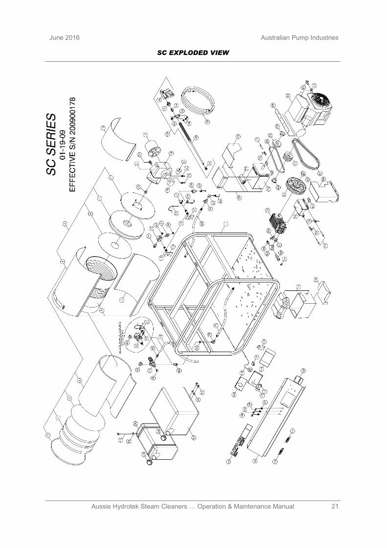
SC EXPLODED VIEW
22 Aussie Hydrotek Steam Cleaners … Operation & Maintenance Manual
Australian Pump Industries June 2016
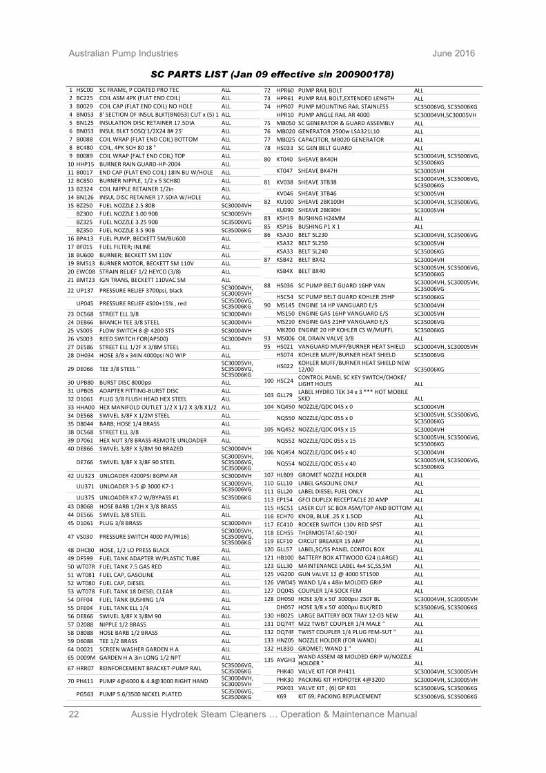
SC PARTS LIST (Jan 09 effective s/n 200900178)
1 HSC00 SC FRAME, P COATED PRO TEC ALL
2 BC225 COIL ASM 4PK (FLAT END COIL) ALL
3 B0029 COIL CAP (FLAT END COIL) NO HOLE ALL
4 BN053 8' SECTION OF INSUL BLKT(BN053) CUT x (5) 1 ALL
5 BN125 INSULATION DISC RETAINER 17.5DIA ALL
6 BN053 INSUL BLKT 5OSQ’1/2X24 8# 25' ALL
7 B0088 COIL WRAP (FLAT END COIL) BOTTOM ALL
8 BC480 COIL, 4PK SCH 80 18 " ALL
9 B0089 COIL WRAP (FALT END COIL) TOP ALL
10 HHP15 BURNER RAIN GUARD-HP-2004 ALL
11 B0017 END CAP (FLAT END COIL) 18IN BU W/HOLE ALL
12 BC850 BURNER NIPPLE, 1/2 x 5 SCH80 ALL
13 B2324 COIL NIPPLE RETAINER 1/2in ALL
14 BN126 INSUL DISC RETAINER 17.5DIA W/HOLE ALL
15 BZ250 FUEL NOZZLE 2.5 80B SC30004VH
BZ300 FUEL NOZZLE 3.00 90B SC30005VH
BZ325 FUEL NOZZLE 3.25 90B SC35006VG
BZ350 FUEL NOZZLE 3.5 90B SC35006KG
16 BPA13 FUEL PUMP, BECKETT SM/BU600 ALL
17 BF015 FUEL FILTER; INLINE ALL
18 BU600 BURNER; BECKETT SM 110V ALL
19 BM513 BURNER MOTOR, BECKETT SM 110V ALL
20 EWC08 STRAIN RELIEF 1/2 HEYCO (3/8) ALL
21 BMT23 IGN TRANS, BECKETT 110VAC SM ALL
22 UP137 PRESSURE RELIEF 3700psi, black SC30004VH, SC30005VH
UP045 PRESSURE RELIEF 4500+15% , red SC35006VG, SC35006KG
23 DC568 STREET ELL 3/8 SC30004VH
24 DEB66 BRANCH TEE 3/8 STEEL SC30004VH
25 VS005 FLOW SWITCH 8 @ 4200 ST5 SC30004VH
26 VS003 REED SWITCH FOR(AP500) SC30004VH
27 DE586 STREET ELL 1/2F X 3/8M STEEL ALL
28 DH034 HOSE 3/8 x 34IN 4000psi NO WIP ALL
29 DE066 TEE 3/8 STEEL " SC30005VH, SC35006VG, SC35006KG
30 UPB80 BURST DISC 8000psi ALL
31 UPB05 ADAPTER FITTING-BURST DISC ALL
32 D1061 PLUG 3/8 FLUSH HEAD HEX STEEL ALL
33 HHA00 HEX MANIFOLD OUTLET 1/2 X 1/2 X 3/8 X1/2 ALL
34 DE568 SWIVEL 3/8F X 1/2M STEEL ALL
35 D8044 BARB; HOSE 1/4 BRASS ALL
38 DC568 STREET ELL 3/8 ALL
39 D7061 HEX NUT 3/8 BRASS-REMOTE UNLOADER ALL
40 DE866 SWIVEL 3/8F X 3/8M 90 BRAZED SC30004VH
DE766 SWIVEL 3/8F X 3/8F 90 STEEL SC30005VH, SC35006VG, SC35006KG
42 UU323 UNLOADER 4200PSI 8GPM AR SC30004VH
UU371 UNLOADER 3-5 @ 3000 K7-1 SC30005VH, SC35006VG
UU375 UNLOADER K7-2 W/BYPASS #1 SC35006KG
43 D8068 HOSE BARB 1/2H X 3/8 BRASS ALL
44 DE566 SWIVEL 3/8 STEEL ALL
45 D1061 PLUG 3/8 BRASS SC30004VH
47 VS030 PRESSURE SWITCH 4000 PA/PR16] SC30005VH, SC35006VG, SC35006KG
48 DHC80 HOSE, 1/2 LO PRESS BLACK ALL
49 DF599 FUEL TANK ADAPTER W/PLASTIC TUBE ALL
50 WT07R FUEL TANK 7.5 GAS RED ALL
51 WT081 FUEL CAP, GASOLINE ALL
52 WT080 FUEL CAP, DIESEL ALL
53 WT078 FUEL TANK 18 DIESEL CLEAR ALL
54 DFF04 FUEL TANK BUSHING 1/4 ALL
55 DFE04 FUEL TANK ELL 1/4 ALL
56 DE866 SWIVEL 3/8F X 3/8M 90 ALL
57 D2088 NIPPLE 1/2 BRASS ALL
58 D8088 HOSE BARB 1/2 BRASS ALL
59 D6088 TEE 1/2 BRASS ALL
64 D0021 SCREEN WASHER GARDEN H A ALL
65 D009M GARDEN H A 3in LONG 1/2 NPT ALL
67 HRR07 REINFORCEMENT BRACKET-PUMP RAIL SC35006VG, SC35006KG
70 PH411 PUMP 4@4000 & 4.8@3000 RIGHT HAND SC30004VH, SC30005VH
PG563 PUMP 5.6/3500 NICKEL PLATED SC35006VG, SC35006KG
72 HPR60 PUMP RAIL BOLT ALL 73 HPR61 PUMP RAIL BOLT,EXTENDED LENGTH ALL
74 HPR07 PUMP MOUNTING RAIL STAINLESS SC35006VG, SC35006KG
HPR10 PUMP ANGLE RAIL AR 4000 SC30004VH,SC30005VH
75 MB050 SC GENERATOR & GUARD ASSEMBLY ALL
76 MB020 GENERATOR 2500w LSA321L10 ALL
77 MB025 CAPACITOR, MB020 GENERATOR ALL
78 HS033 SC GEN BELT GUARD ALL
80 KT040 SHEAVE BK40H SC30004VH, SC35006VG, SC35006KG
KT047 SHEAVE BK47H SC30005VH
81 KV038 SHEAVE 3TB38 SC30004VH, SC35006VG, SC35006KG
KV046 SHEAVE 3TB46 SC30005VH
82 KU100 SHEAVE 2BK100H SC30004VH, SC35006VG,
KU090 SHEAVE 2BK90H SC30005VH
83 KSH19 BUSHING H24MM ALL
85 KSP16 BUSHING P1 X 1 ALL
86 KSA30 BELT 5L230 SC30004VH, SC35006VG
KSA32 BELT 5L250 SC30005VH
KSA33 BELT 5L240 SC35006KG
87 KSB42 BELT BX42 SC30004VH
KSB4X BELT BX40 SC30005VH, SC35006VG, SC35006KG
88 HS036 SC PUMP BELT GUARD 16HP VAN SC30004VH, SC30005VH, SC35006VG
HSC54 SC PUMP BELT GUARD KOHLER 25HP SC35006KG
90 MS145 ENGINE 14 HP VANGUARD E/S SC30004VH
MS150 ENGINE GAS 16HP VANGUARD E/S SC30005VH
MS210 ENGINE GAS 21HP VANGUARD E/S SC35006VG
MK200 ENGINE 20 HP KOHLER CS W/MUFFL SC35006KG
93 MS006 OIL DRAIN VALVE 3/8 ALL
95 HS021 VANGUARD MUFF/BURNER HEAT SHIELD SC30004VH, SC30005VH
HS074 KOHLER MUFF/BURNER HEAT SHIELD SC35006VG
HS022 KOHLER MUFF/BURNER HEAT SHIELD NEW 12/00 SC35006KG
100 HSC24 CONTROL PANEL SC KEY SWITCH/CHOKE/LIGHT HOLES ALL
103 GLL79 LABEL HYDRO TEK 34 x 3 *** HOT MOBILE SKID ALL
104 NQ450 NOZZLE/QDC 045 x 0 SC30004VH
NQ550 NOZZLE/QDC 055 x 0 SC30005VH, SC35006VG, SC35006KG
105 NQ452 NOZZLE/QDC 045 x 15 SC30004VH
NQ552 NOZZLE/QDC 055 x 15 SC30005VH, SC35006VG, SC35006KG
106 NQ454 NOZZLE/QDC 045 x 40 SC30004VH
NQ554 NOZZLE/QDC 055 x 40 SC30005VH, SC35006VG, SC35006KG
107 HLB09 GROMET NOZZLE HOLDER ALL
110 GLL10 LABEL GASOLINE ONLY ALL
111 GLL20 LABEL DIESEL FUEL ONLY ALL
113 EP154 GFCI DUPLEX RECEPTACLE 20 AMP ALL
115 HSC51 LASER CUT SC BOX ASM/TOP AND BOTTOM ALL
116 ECH70 KNOB, BLUE .25 X 1.5OD ALL
117 EC410 ROCKER SWITCH 110V RED SPST ALL
118 ECH55 THERMOSTAT,60-190F ALL
119 ECF10 CIRCUT BREAKER 15 AMP ALL
120 GLL57 LABEL,SC/SS PANEL CONTOL BOX ALL
121 HB100 BATTERY BOX ATTWOOD G24 (LARGE) ALL
123 GLL30 MAINTENANCE LABEL 4x4 SC,SS,SM ALL
125 VG200 GUN VALVE 12 @ 4000 ST1500 ALL
126 VW045 WAND 1/4 x 48in MOLDED GRIP ALL
127 DQ04S COUPLER 1/4 SOCK FEM ALL
128 DH050 HOSE 3/8 x 50' 3000psi 250F BL SC30004VH, SC30005VH
DH057 HOSE 3/8 x 50' 4000psi BLK/RED SC35006VG, SC35006KG
130 HB025 LARGE BATTERY BOX TRAY 12-03 NEW ALL
131 DQ74T M22 TWIST COUPLER 1/4 MALE " ALL
132 DQ74F TWIST COUPLER 1/4 PLUG FEM-SUT " ALL
133 HNZ05 NOZZLE HOLDER (FOR WAND) ALL
132 HLB30 GROMET; WAND 1 " ALL
135 AVGH3 WAND ASSEM 48 MOLDED GRIP W/NOZZLE HOLDER " ALL
PHK40 VALVE KIT FOR PH411 SC30004VH, SC30005VH
PHK30 PACKING KIT HYDROTEK 4@3200 SC30004VH, SC30005VH
PGK01 VALVE KIT ; (6) GP K01 SC35006VG, SC35006KG
K69 KIT 69; PACKING REPLACEMENT SC35006VG, SC35006KG
23 Aussie Hydrotek Steam Cleaners … Operation & Maintenance Manual
June 2016 Australian Pump Industries
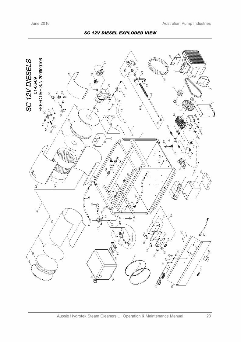
SC 12V DIESEL EXPLODED VIEW
24 Aussie Hydrotek Steam Cleaners … Operation & Maintenance Manual
Australian Pump Industries June 2016
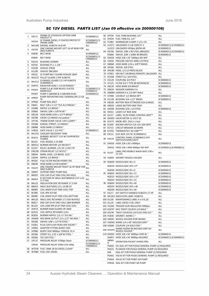
SC 12V DIESEL PARTS LIST (Jan 09 effective s/n 200900108)
1 HSC71 FRAME-SC STAINLESS-OPTION-2008 PROTECT IT SC30006D12
HSC63 SC FRAME DIESEL; P COATED PROTECTIT FRAME-2008
SC35006D12,SC40006D12
2 MU168 ENGINE, KUBOTA 16.8 HP ALL
3 HS228 ZINC ENGINE MOUNT LEFT 16 HP NEW FOR Z602 KUBOTA ALL
4 KSB38 BELT BX38 SC30006D12
KSB4X BELT BX40 SC35006D12,SC40006D12
5 KSH19 BUSHING H24MM ALL
6 KSP18 BUSHING P1 x 1 1/8 " ALL
7 KV038 SHEAVE 3TB38 ALL
8 KU100 SHEAVE 2BK100H ALL
9 HSC61 SC PUMP BELT GUARD KOHLER 18HP ALL
10 MU222 PULLEY GUARD 17HP KUBOTA ALL
11 MU212 FLYWHEEL GUARD 12.5 HP KUBOTA SC30006D12 ALL
12 DHR75 RADIATOR HOSE 1 1/4 EXTENDED " ALL
13 PG563 PUMP 5.6 @ 3500 NICKEL PLATED MANIFOLD
SC30006D12,SC35006D12
PH407 PUMP 5.5@4060 & 4.5@4400 DUAL SC40006D12
14 HPR07 PUMP MOUNTING RAIL-GENERAL/AR 12 GA SS ALL
15 HPR60 PUMP RAIL BOLT ALL
16 FB641 BOLT 3/8 x 2 1/2" PLD ALLTHREAD " ALL
17 D2088 NIPPLE 1/2 BRASS " ALL
18 DE866 SWIVEL 3/8F x 3/8"M 90 " ALL
19 D8128 HOSE BARB 3/4H x 1/2"P BRASS " ALL
20 D6788 CROSS 1/2 BRASS-not potted " ALL
21 UPT46 THERM DUMP VALVE 145f 1/2MPT " ALL
22 D5588 ELBOW; STREET; 1/2 BRASS " ALL
23 D8088 HOSE BARB 1/2 BRASS " ALL
24 VVB10 GATE VALVE 1 1/2 PVC " SC30006D12
25 MU155 COOLANT RECOVERY TANK ALL
26 BU013 BURNER; BECKETT 12V W/ SUPPORTED FLANGE ALL
27 BZ225 FUEL NOZZEL 2.25 80B ALL
28 BM514 BURNER MOTOR 12V BECKETT ALL
29 ECC07 RELAY; BURNER; 12V DC ( CAN TYP ALL
30 EWC08 STRAIN RELIEF 1/2 HEYCO " ALL
31 D8044 BARB; HOSE; 1/4 BRASS .312t " ALL
32 D2044 NIPPLE 1/4 BRASS " ALL
33 BF020 FUEL FILTER RACOR HYDRO TEK ALL
34 D8040 HOSE BARB 1/4 90 ELBOW " ALL
35 HS229 ZINC ENGINE MOUNT RIGHT 16 HP NEW FOR Z602 KUBOTA ALL
36 HRR07 SUPPORT BRKT-PUMP RAIL ALL
37 B0029 COIL CAP (FLAT END COIL) NO HOLE ALL
38 BN053 8' SECTION OF INSUL BLKT(BN053) CUT x (5) 17.5 DIA ALL
39 BN125 INSULATION DISC RETAINER 17.5 DIA ALL
40 BN053 INSUL BLKT50SQ 1/2 x 24 8# 25' ALL
41 B0089 COIL WRAP (FLAT END COIL) TOP ALL
42 BC480 COIL 4PK SCH 80 ALL
43 B0088 COIL WRAP (FLAT END COIL) BOTTOM ALL
44 BN126 INSUL DISC RETAINER 17.5 DIA W/HOLE ALL
45 B0017 END CAP (FLAT END COIL) 18IN BURNER ALL
46 BC225 COIL ASM 4PK (FLAT END COIL) 5/01 ALL
47 HHP15 BURNER RAIN GUARD-HP-2004 ALL
48 B2324 COIL NIPPLE RETAINER 1/2in ALL
49 BC850 BURNER NIPPLE 1/2 x 5' SCH 80 " ALL
50 HHA00 HEX MANI OUTLET 1/2 x 1/2" NO REEL " ALL
51 DE568 SWIVEL 3/8F x 1/2"M STEEL " ALL
52 D1061 PLUG 3/8 FLUSH HEAD HEX SOCKET " ALL
53 UPB05 ADAPTER FITTING-BURST DISC ALL
54 UPB80 BURST DISC 8000psi TORQUE 32-4 ALL
55 DE586 STREET ELL 1/2F x 3/8"M STEEL " ALL
56 DE066 TEE 3/8 STEEL " ALL
57 UP137 PRESSURE RELIEF 3700psi black SC30006D12
UP045 PRESSURE RELIEF 4500+15% 500q SC35006D12,SC40006D12
58 WT078 FUEL TANK 18 GA DIESEL CLEAR* ALL
59 WT080 FUEL CAP; DIESEL ALL
60 DFF04 FUEL TANK BUSHING 1/4 " ALL
61 DFE04 FUEL TANK ELL 1/4 " ALL
62 FC084 WORMGEAR CLAMP 2 1/2 x 20 ALL
63 UU371 UNLOADER 3-5 @ 3500 K7-1 SC30006D12,SC35006D12
UU323 UNLOADER 4350psi 8GPM AR SC40006D12
64 DE766 SWIVEL 3/8F x 90 STEEL (BRAZED) SC30006D12,SC35006D12
DE866 SWIVEL 3/8F x 3/8M 90 BRAZED SC40006D12
65 DH034 HOSE 3/8 x 34" 5000psi NO WIP ALL
66 VS030 PRESURE SWITCH 4000 1/4 PR16 ALL
67 D8068 HOSE BARB 1/2H x 3/8"P BRASS ALL
68 DE566 SWIVEL 3/8 STEEL ALL
69 DHC80 HOSE; 1/2 LO PRESS BLACK ALL
70 D7061 HEX NUT 3/8 BRASS-REMOTE UNLOADER ALL
71 DC568 STREET ELL 3/8 STEEL ALL
72 D3120 COUPLING 3/4 POLY SC30006D12
73 VF125 FILTER 3/4 Y TYPE 80 MICRON/20 SC30006D12
74 D8120 HOSE BARB 3/4 BRASS* SC30006D12
75 D0020 WASHER GARDEN H A ALL
76 D008M GARDEN H A 1/2 NPT MALE ALL
77 D7080 LOCKNUT 1/2 BRASS NPT SC30006D12
78 D1128 BUSHING 3/4 x 1/2" BRASS SC30006D12
79 HB100 BATTERY BOX ATTWOOD G24 (LARGE) ALL
80 HB026 LARGE BATTERY BOX TRAY ALL
81 DA046 BUSHING 3/8 x 1/4 STEEL SC40006D12
82 HSS51 LASER CUT BOX ASM ALL
83 GLL57 LABEL; SC/SS PANEL CONTROL BOX** ALL
84 EM305 HOUR METER 12 VOLT DC ALL
85 ECH72 KNOB; RED .25id x 1.5od ALL
86 EC405 ROCKER SWITCH CLR 12V 20A DPST ALL
87 ECF15 CIRCUIT BREAKER 20 AMP8 ALL
88 ECH55 THERMOSTAT; 60-190F*** ALL
89 ESC12 ELEC BOX 12V DC SC30006D12 ALL
90 HSC24 CONTROL PANEL SC30006D12 KEY SWITCH/CHOKE/LIGHT ALL
91 DH026 HOSE 3/8 x 26.5 4000psi SC30006D12
DH032 HOSE 3/8 x 30IN 4000psi NO WIP SC35006D12,SC40006D12
92 GLL97 LABEL PRO MOBILE WASH SKID 3.00 x 21.125 ALL
93 HLB09 GROMET NOZZLE HOLDER ALL
94 NQ600 NOZZLE/QDC 06 x 0 SC30006D12
NQ550 NOZZLE/QDC 055 x 0* SC35006D12
NQ500 NOZZLE/QDC 05 x 0 SC40006D12
95 NQ602 NOZZLE/QDC 06 x 15 SC30006D12
NQ552 NOZZLE/QDC 055 x 15* SC35006D12
NQ502 NOZZLE/QDC 05 x 15 SC40006D12
96 NQ604 NOZZLE/QDC 06 x 40 SC30006D12
NQ554 NOZZLE/QDC 055 x 40 SC35006D12
NQ504 NOZZLE/QDC 05 x 40 SC40006D12
97 ESC17 KEY SWITCH HARNESS KUBOTA-17 HP ALL
99 MU262 INDICATOR LAMP: KOBOTA ALL
100 GLL30 MAINTENANCE LABEL 4 x 4 SC,SS ALL
101 GLL20 LABEL DIESEL FUEL ONLY ALL
102 VG200 TRIGGER GUN INSULATED 4000psi ALL
103 DQ74T M22 TWIST COUPLR 1/4 MALE " ALL
104 DQ74F TWIST COUPLER 1/4 PLUG FEM-SUT " ALL
105 HLB30 GROMET; WAND 1 " ALL
106 HNZ05 NOZZLE HOLDER (FOR WAND) ALL
107 VW045 WAND 1/4 x 48" MOLDED GRIP " ALL
108 DQ04S COUPLER 1/4 SOCK FEM " ALL
109 AVGH3 WAND ASSEM 48 MOLDED GRIP W/NOZZLE HOLDER " ALL
110 DH050 HOSE 3/8 x 50' 3000psi 250F BL " SC30006D12
DH057 HOSE 3/8 x 50' 4000psi BLK/RED SC35006D12,SC40006D12
ABMAG OPERATION PACKET HYDRO PRO ALL
PGK02 OIL SEAL KIT FOR PG563 GENERAL PUMP (1) REQUIRED
PGK21 PLUNGER FOR PG563 GENERAL PUMP (3) REQUIRED
K69 SEAL KIT FOR PG563 GENERAL PUMP (1) REQUIRED
PGK01 VALVE KIT FOR PG563 GENERAL PUMP (1) REQUIRED
PHK64 VALVE KIT FOR PH407 AR PUMP
PHK58 SEAL KIT FOR PH407 AR PUMP
25 Aussie Hydrotek Steam Cleaners … Operation & Maintenance Manual
June 2016 Australian Pump Industries
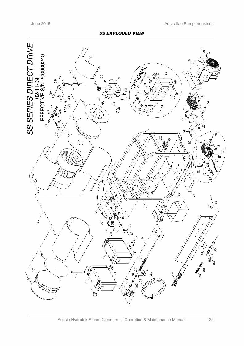
SS EXPLODED VIEW
6a
26 Aussie Hydrotek Steam Cleaners … Operation & Maintenance Manual
Australian Pump Industries June 2016
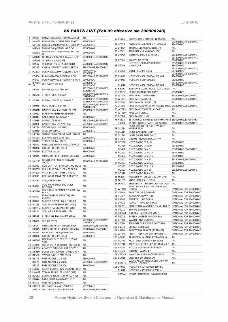
SS PARTS LIST (Feb 09 effective s/n 200900240)
57 DE766 SWIVEL 3/8F x 90 STEEL (BRAZED) ALL
58 VC037 CHEMICAL INJECTOR ADJ. 4000psi SS32004HG,SS38004VG, SS40004VC
59 DHB04 TUBING; CLEAR BRAIDED; 1/4 ALL
60 VF042 STRAINER CHEM (NO CHECK) ALL
61 DA064 BUSHING 3/8M x 1/4 STEEL SS38004VG,SS40004VC
62 DE566 SWIVEL 3/8 STEEL SS32004HG,SS38004VG, SS40004VC
63 D7061 HEX NUT 3/8 BRASS-REMOTE UNLOADER
SS32004HG,SS38004VG, SS40004VC
64 DC568 STREET ELL 3/8 STEEL SS32004HG,SS38004VG, SS40004VC
65 DH026 HOSE 3/8 x 30in 5000psi NO WIP SS32004HG,SS38004VG, SS40004VC
66 DH003 HOSE 3/8 x 18in 5000psi SS30003HG
DH032 HOSE 3/8 x 30in 5000psi NO WIP SS32004HG,SS38004VG, SS40004VC
67 HB100 BATTERY BOX ATTWOOD G24 (LARGE) ALL
68 HB025 LARGE BATTERY BOX TRAY SS38004VG
69 WT07R FUEL TANK 7.5 GAS RED SS38004VG,SS40004VC
70 WT081 FUEL CAP; GASOLINE SS38004VG,SS40004VC
71 DFF04 FUEL TANK BUSHING 1/4 ALL
72 DF599 FUEL TANK ADAPTER W/PLASTIC TUBE SS38004VG,SS40004VC
73 WT075 FUEL TANK 7.5 DIESEL CLEAR* ALL
74 WT080 FUEL CAP; DIESEL ALL
75 DFE04 FUEL TANK ELL 1/4 ALL
76 HSS12 SS CONTROL PANEL-SS32004HH 37186 SS30003HG,SS32004HG
HSS03 SS PROLINECON PANEL NO RADIUS SS38004VG,SS40004VC
78 GLL79 LABEL HYDRO TEK 34 x 3*** HOT MOBILE SKID ALL
79 GLL10 LABEL GASOLINE ONLY ALL
80 GLL20 LABEL DIESEL FUEL ONLY ALL
81 HLB09 GROMET NOZZLE HOLDER*** ALL
82 NQ350 NOZZLE/QDC 035 x 0 SS30003HG
NQ450 NOZZLE/QDC 045 x 0 SS32004HG
NQ400 NOZZLE/QDC 04 x 0 SS38004VG,SS40004VC
83 NQ352 NOZZLE/QDC 035 x 15 SS30003HG
NQ452 NOZZLE/QDC 045 x 15 SS32004HG
NQ402 NOZZLE/QDC 04 x 15 SS38004VG,SS40004VC
84 NQ253 NOZZLE/QDC 025 x 25 SS30003HG
NQ353 NOZZLE/QDC 035 x 25 SS32004HG
NQ303 NOZZLE/QDC 03 x 25 SS38004VG,SS40004VC
85 NQ970 NOZZLE/QDC 40.0 x 65 ALL
86 EC405 ROCKER SWITCH CLR 12V 20A DPST ALL
87 ECH72 KNOB; RED .25 x 1.50od ALL
88 ECH50 THERMASTAT; 60-260 1 GP PART=25 ALL
89 WT040 TANK, FLOAT 4 GAL HD LINEAR (NO HOLES) OPTIONAL FOR SS40004VC
90 VVF08 FLOAT VALVE 3/8 BRASS OPTIONAL FOR SS40004VC
91 HL017 TANK CAP 4in W/HOLE OPTIONAL FOR SS40004VC
92 D5566 STREET ELL 3/8 BRASS OPTIONAL FOR SS40004VC
93 D7520 PANEL FITTING 3/4 BRASS OPTIONAL FOR SS40004VC
94 FW701 FLOAT TANK WASHER 1.75od 14GA SS OPTIONAL FOR SS40004VC
95 D0010 SPRING GARDEN H A OPTIONAL FOR SS40004VC
96 D006M GARDEN H A 3/8 NPT MALE OPTIONAL FOR SS40004VC
97 D0021 SCREEN WASHER GARDEN H A OPTIONAL FOR SS40004VC
98 DFF10 WATER TANK BUSHING OPTIONAL FOR SS40004VC
99 VF050 STRAINER TUBE FOR FLOAT TANK OPTIONAL FOR SS40004VC
100 D1010 SPLICER 5/8 BRASS OPTIONAL FOR SS40004VC
101 HSS20 FLOAT TANK SPACER (SS SERIES) OPTIONAL FOR SS40004VC
102 WT046 FLOAT TANK ASM W/VALVE/FILTER OPTIONAL FOR SS40004VC
103 VG200 TRIGGER GUN, INSULATED 4000psi ALL
104 DQ74T M22 TWIST COUPLER 1/4 MALE " ALL
105 DQ74F TWIST COUPLER 1/4 PLUG FEM-sut " ALL
106 HNZ05 NOZZLE HOLDER (FOR WAND) ALL
107 HLB30 GROMET; WAND 1 " ALL
108 VW045 WAND 1/4 x 48in MOLDED GRIP ALL
109 DQ04S COUPLER 1/4 SOCK FEM ALL
110 AVGH3 WAND ASSEM 48 MOLDED GRIP W/NOZZLE HOLDER " ALL
111 DH050 HOSE 3/8 x 50' 3000psi 250f BL
DH057 HOSE 3/8 x 50' 4000psi 250f re
ABMAG OPERATION PACKET GENERAL PRO
1 HSS00 FRAME STACKABLE B/D SS ASSEM ALL
2 MH009 ENGINE 9hp HONDA PULL START SS30003HG
MH135 ENGINE 13hp HONDA E/S 18amp*** SS32004HG
MS145 ENGINE 14hp VANGUARD E/S SS38004VG
MS150 ENGINE GAS 16hp VANGUARD E/S W SS40004VC
3 MKD13 OIL DRAIN ADAPTER 12mm x 3/8 " SS30003HG,SS32004HG
4 MS006 OIL DRAIN VALVE 3/8 ALL
5 HSS17 SS EXAUST/FUEL TANK SHIELD SS30003HG,SS32004HG
HSS05 VAN MUFF/HEAT SHIELD LEFT #1 SS38004VG,SS40004VC
6 PG303 PUMP 3@3500 W/UNL/INJ 1 GAS " SS30003HG, SS35003DG
PG404 PUMP 4@4000; GENERAL 1 DD SS32004HG,SS38004VG
P4060 PUMP 66DX40G1I 4000 @ 4 SHAFT SS40004VC
6a BIPKIT137 UNLOADER KIT 137 SS30003HG,
SS35003DG
7 DE866 SWIVEL 3/8F x 3/8M 90 SS32004HG,SS38004VG,SS40004VC
8 D6588 STREET TEE 1/2 BRASS SS32004HG,SS38004VG,SS40004VC
9 D5588 ELBOW, STREET 1/2 BRASS " SS30003HG,SS32004HG,SS38004VG,SS40004VC
10 D8088 HOSE BARB 1/2 BRASS SS32004HG,SS38004VG,SS40004VC
11 D009M GARDEN H A 3in LONG 1/2 NPT SS30003HG,SS40004VC
12 D0021 SCREEN WASHER GARDEN H A ALL
13 D8044 BARB, HOSE 1/4 BRASS " SS40004VC
14 D2088 NIPPLE 1/2 BRASS SS32004HG,SS38004VG
15 D008F GARDEN H A 1/2 NPT FEM SS32004HG,SS38004VG
16 DE766 SWIVEL 3/8F x 90 STEEL SS30003HG
17 D1040 PLUG 1/4 BRASS SS30003HG
18 UPT46 THERM DUMP VALVE 145f 1/2MPT ALL
19 DA064 BUSHING 3/8 x 1/4 STEEL SS30003HG
20 DC043 STREET ELL 1/4, STEEL SS30003HG
21 VS030 PRESSURE SWITCH 4000 1/4 PR16 " ALL
22 DEB66 BRANCH TEE 3/8 STEEL SS40004VC
23 VA010 EZ START VALVE SS40004VC
24 UP045 PRESSURE RELIEF 4500+15% 500q SS40004VC
25 MH225 HONDA VOLTAGE REGULATOR GX270 SS30003HG,SS32004HG
26 B0029 COIL CAP (FLAT END COIL) NO HOLE ALL
27 BN053 INSUL BLKT 50sq' 1/2 x 24 8# 25' ALL
28 BN125 INSUL DISC RETAINER 17.5DIA ALL
29 B0089 COIL WRAP (FLAT END COIL) TOP ALL
30 BC480 COIL, 4PK SCH 80 ALL
31 B0088 COIL WRAP (FLAT END COIL) BOTTOM ALL
32 BN126 INSUL DISC RETAINER 17.5 DIA. W/HOLE ALL
33 B0017 END CAP (FLAT END COIL) 18in BURNER ALL
34 BC850 BURNER NIPPLE; 1/2 x 5 SCH80 ALL
35 BC225 COIL ASM 4PK (FLAT END COIL) ALL
36 HHP15 BURNER RAINGUARD-HP-2004 ALL
37 B2324 COIL NIPPLE RETAINER 1/2in ALL
38 DE586 STREET ELL 1/2F x 3/8M STEEL ALL
39 DE066 TEE 3/8 STEEL SS32004HG,SS38004VG,SS40004VC
40 UP137 PRESSURE RELIEF 3700psi black SS30003HG,SS32004HG
UP045 PRESSURE RELIEF 4500+15% 500q SS38004VG,SS40004VC
41 VS005 FLOW SWITCH 8 @ 4200 ST5 SS30003HG
42 DEB66 BRANCH TEE 3/8 STEEL SS30003HG
43 HHA00 HEX MANI OUTLET 1/2 x 1/2 NO REEL ALL
44 ECH75 HEAVY DUTY BEND RESTRICTOR -B ALL
45 UPB05 ADAPTER FITING-BURST DISC*** ALL
46 UPB80 BURST DISC 8000psi TORQUE 32-4 ALL
47 DE568 SWIVEL 3/8F x 1/2M STEEL ALL
48 BZ175 FUEL NOZZLE 1.75 80B SS30003HG
BZ225 FUEL NOZZLE 2.25 80B SS32004HG,SS38004VG
BZ226 FUEL NOZZLE 2.25 80A SS40004VC
49 ECC07 RELAY; BURNER 12V DC (CAN TYPE) ALL
50 EWC08 STRAIN RELIEF 1/2 HEYCO (3/8) ALL
51 BU013 BURNER; BECKET 12V W/SUPPORT ALL
52 D8044 BARB; HOSE 1/4 BRASS* .312 t ALL
53 BF015 FUEL FILTER; INLINE ALL
54 UU370 UNLOADER 2-4 @ 3200 K7-0 SS32004HG
UU323 UNLOADER 4350si 8GPM AR SS38004VG,SS40004VC
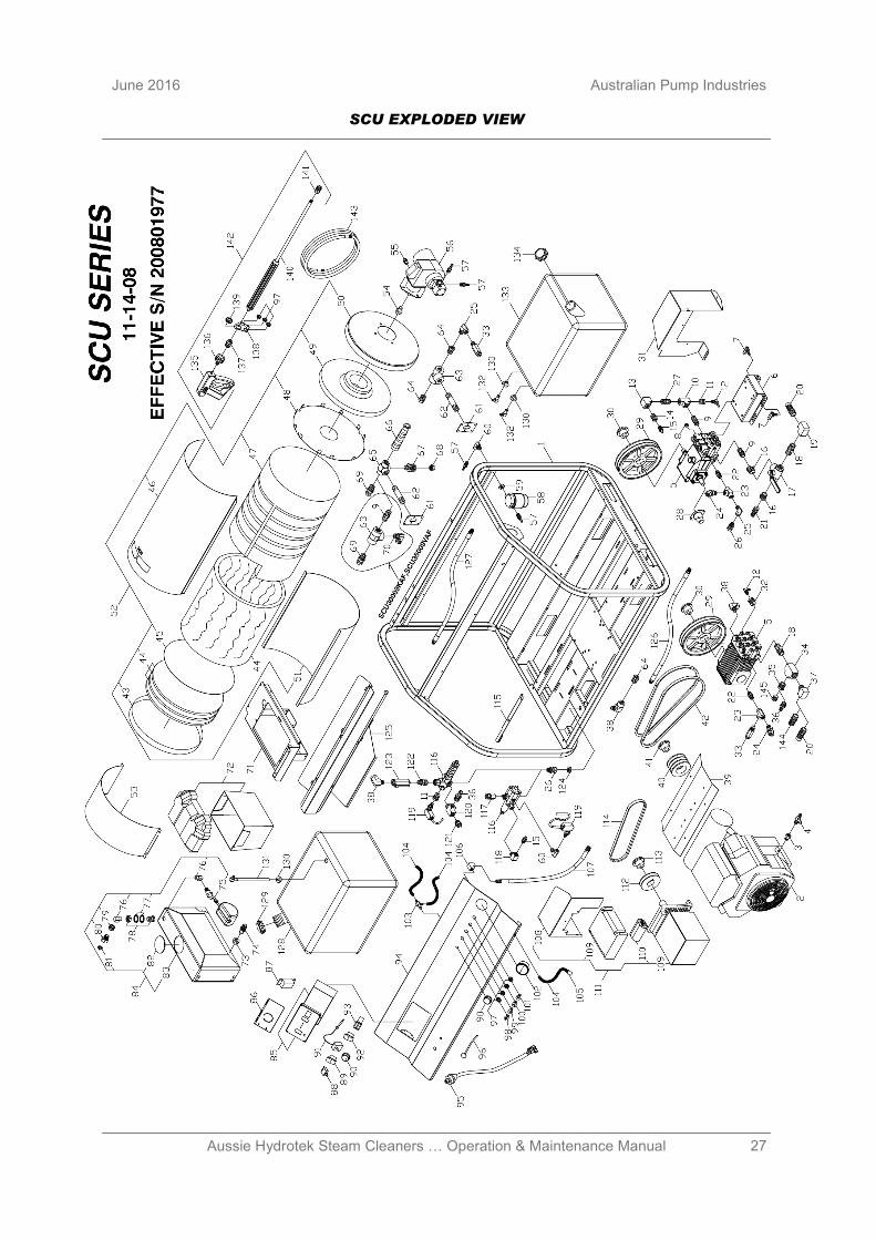
27 Aussie Hydrotek Steam Cleaners … Operation & Maintenance Manual
June 2016 Australian Pump Industries
SCU EXPLODED VIEW
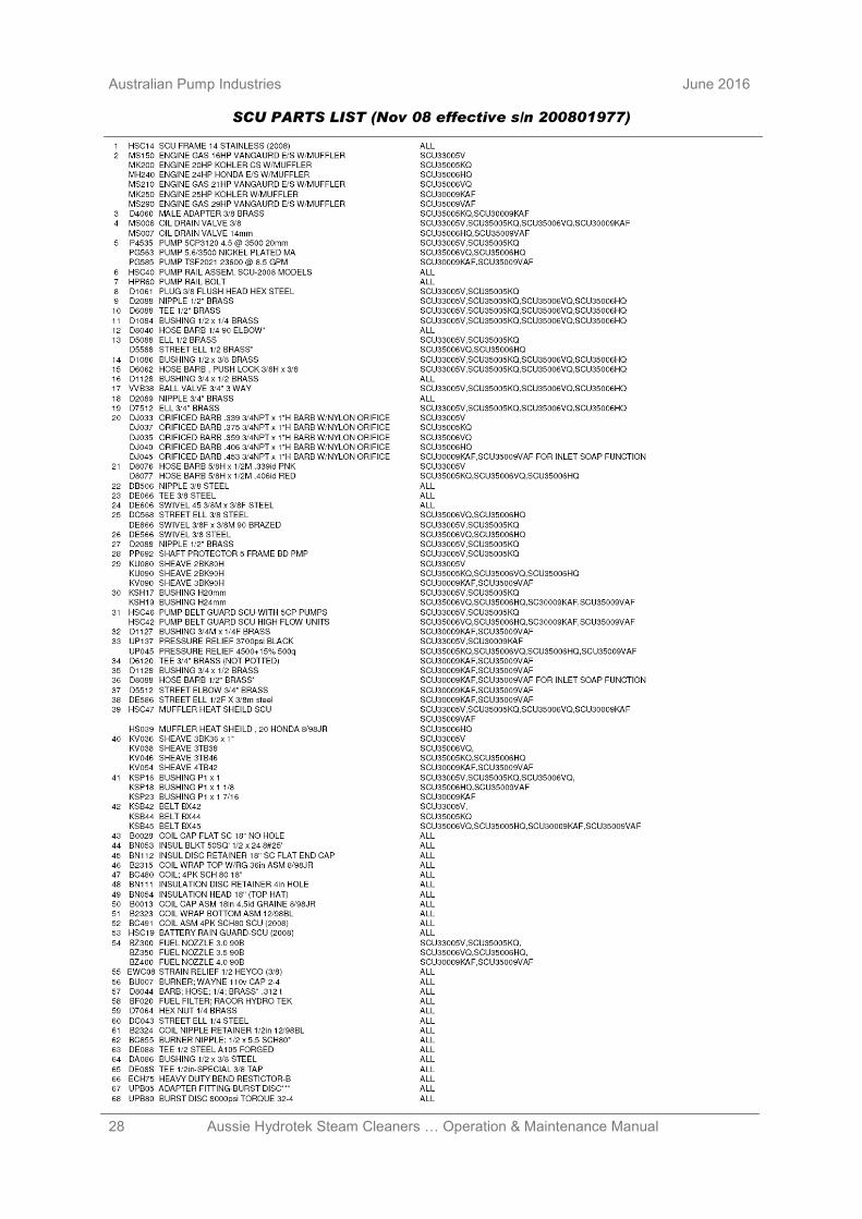
28 Aussie Hydrotek Steam Cleaners … Operation & Maintenance Manual
Australian Pump Industries June 2016
SCU PARTS LIST (Nov 08 effective s/n 200801977)
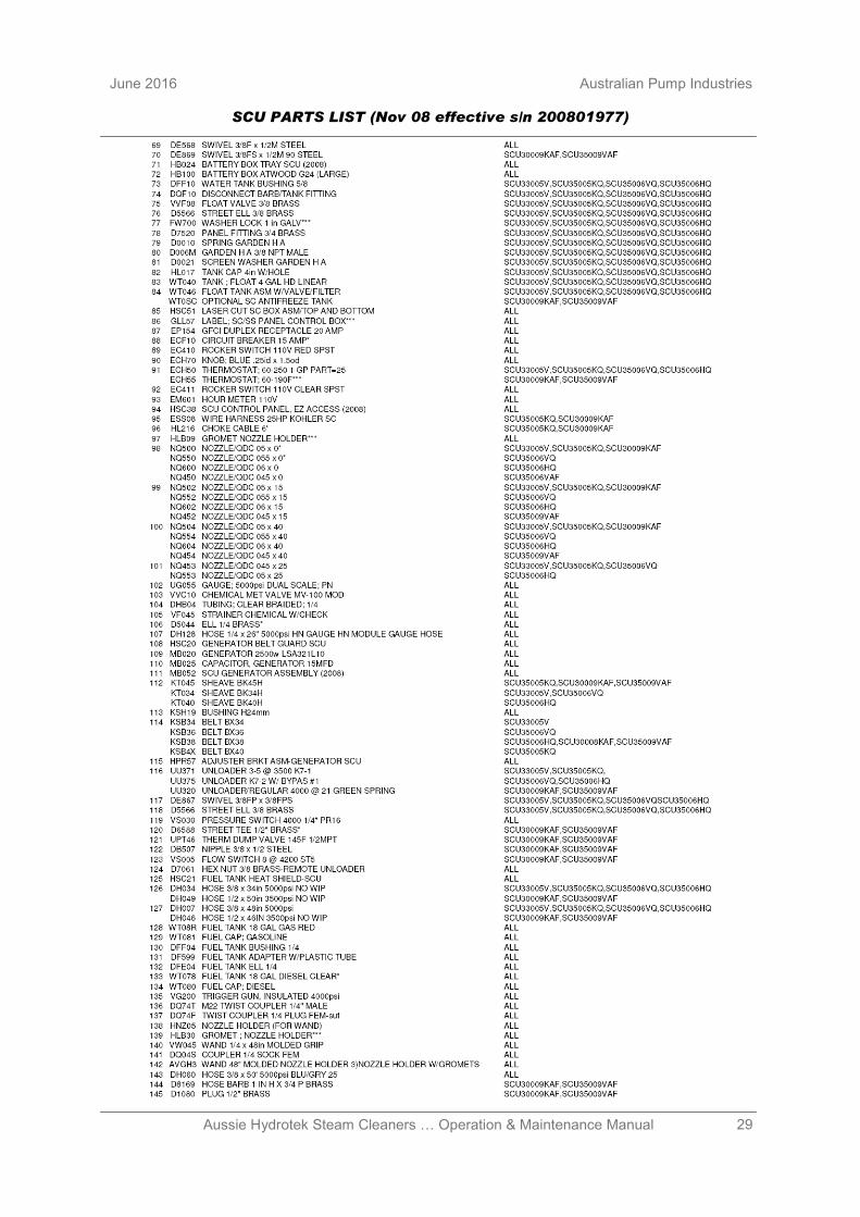
29 Aussie Hydrotek Steam Cleaners … Operation & Maintenance Manual
June 2016 Australian Pump Industries
SCU PARTS LIST (Nov 08 effective s/n 200801977)
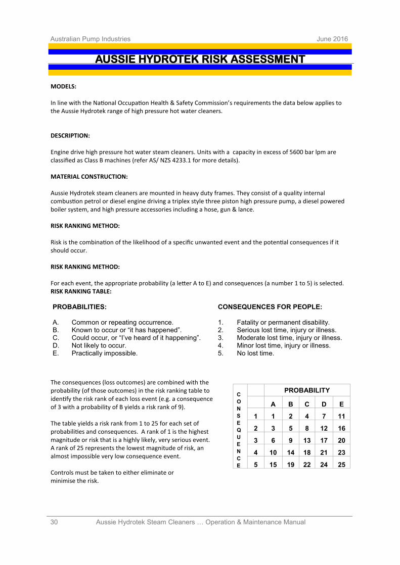
30 Aussie Hydrotek Steam Cleaners … Operation & Maintenance Manual
Australian Pump Industries June 2016
AUSSIE HYDROTEK RISK ASSESSMENT
MODELS: In line with the National Occupation Health & Safety Commission’s requirements the data below applies to the Aussie Hydrotek range of high pressure hot water cleaners. DESCRIPTION: Engine drive high pressure hot water steam cleaners. Units with a capacity in excess of 5600 bar lpm are classified as Class B machines (refer AS/ NZS 4233.1 for more details). MATERIAL CONSTRUCTION: Aussie Hydrotek steam cleaners are mounted in heavy duty frames. They consist of a quality internal combustion petrol or diesel engine driving a triplex style three piston high pressure pump, a diesel powered boiler system, and high pressure accessories including a hose, gun & lance. RISK RANKING METHOD: Risk is the combination of the likelihood of a specific unwanted event and the potential consequences if it should occur. RISK RANKING METHOD: For each event, the appropriate probability (a letter A to E) and consequences (a number 1 to 5) is selected. RISK RANKING TABLE:
The consequences (loss outcomes) are combined with the probability (of those outcomes) in the risk ranking table to identify the risk rank of each loss event (e.g. a consequence of 3 with a probability of B yields a risk rank of 9). The table yields a risk rank from 1 to 25 for each set of probabilities and consequences. A rank of 1 is the highest magnitude or risk that is a highly likely, very serious event. A rank of 25 represents the lowest magnitude of risk, an almost impossible very low consequence event. Controls must be taken to either eliminate or minimise the risk.
C
O
N
S
E
Q
U
E
N
C
E
PROBABILITY
A B C D E
1 1 2 4 7 11
2 3 5 8 12 16
3 6 9 13 17 20
4 10 14 18 21 23
5 15 19 22 24 25
PROBABILITIES: A. Common or repeating occurrence. B. Known to occur or “it has happened”. C. Could occur, or “I’ve heard of it happening”. D. Not likely to occur. E. Practically impossible.
CONSEQUENCES FOR PEOPLE: 1. Fatality or permanent disability. 2. Serious lost time, injury or illness. 3. Moderate lost time, injury or illness. 4. Minor lost time, injury or illness. 5. No lost time.
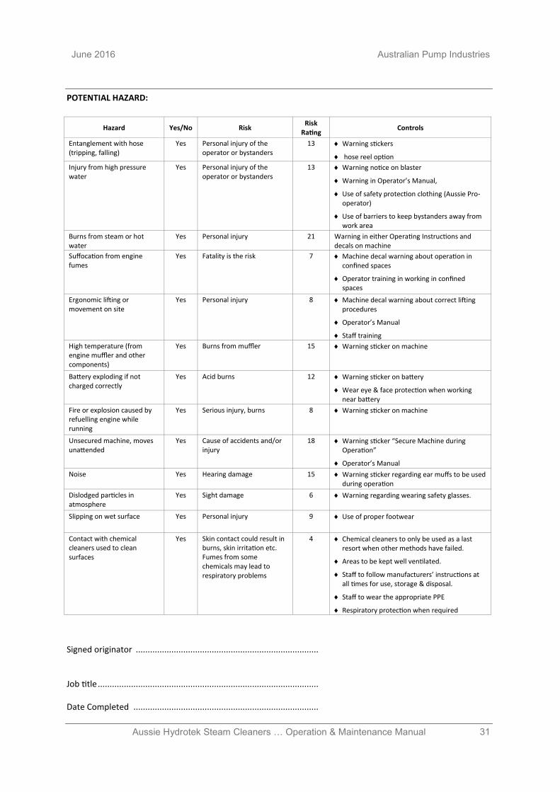
31 Aussie Hydrotek Steam Cleaners … Operation & Maintenance Manual
June 2016 Australian Pump Industries
POTENTIAL HAZARD:
Signed originator ............................................................................. Job title ............................................................................................. Date Completed ..............................................................................
Hazard Yes/No Risk Risk
Rating Controls
Entanglement with hose (tripping, falling)
Yes Personal injury of the operator or bystanders
13 Warning stickers
hose reel option
Injury from high pressure water
Yes Personal injury of the operator or bystanders
13 Warning notice on blaster
Warning in Operator’s Manual,
Use of safety protection clothing (Aussie Pro-operator)
Use of barriers to keep bystanders away from work area
Burns from steam or hot water
Yes Personal injury 21 Warning in either Operating Instructions and decals on machine
Suffocation from engine fumes
Yes Fatality is the risk 7 Machine decal warning about operation in confined spaces
Operator training in working in confined spaces
Ergonomic lifting or movement on site
Yes Personal injury 8 Machine decal warning about correct lifting procedures
Operator’s Manual
Staff training
High temperature (from engine muffler and other components)
Yes Burns from muffler 15 Warning sticker on machine
Battery exploding if not charged correctly
Yes Acid burns 12 Warning sticker on battery
Wear eye & face protection when working near battery
Fire or explosion caused by refuelling engine while running
Yes Serious injury, burns 8 Warning sticker on machine
Unsecured machine, moves unattended
Yes Cause of accidents and/or injury
18 Warning sticker “Secure Machine during Operation”
Operator’s Manual
Noise Yes Hearing damage 15 Warning sticker regarding ear muffs to be used during operation
Dislodged particles in atmosphere
Yes Sight damage 6 Warning regarding wearing safety glasses.
Slipping on wet surface Yes Personal injury 9 Use of proper footwear
Contact with chemical cleaners used to clean surfaces
Yes Skin contact could result in burns, skin irritation etc. Fumes from some chemicals may lead to respiratory problems
4 Chemical cleaners to only be used as a last resort when other methods have failed.
Areas to be kept well ventilated.
Staff to follow manufacturers’ instructions at all times for use, storage & disposal.
Staff to wear the appropriate PPE
Respiratory protection when required

32 Aussie Hydrotek Steam Cleaners … Operation & Maintenance Manual
Australian Pump Industries June 2016
Australian Pump Industries Pty Ltd
7 Gladstone Road, Castle Hill NSW 2154 Ph: (02) 8865 3500 Fax: (02) 9894 4240
www.aussiepumps.com.au [email protected]
Reliable Products … Reliable People
Related Documents