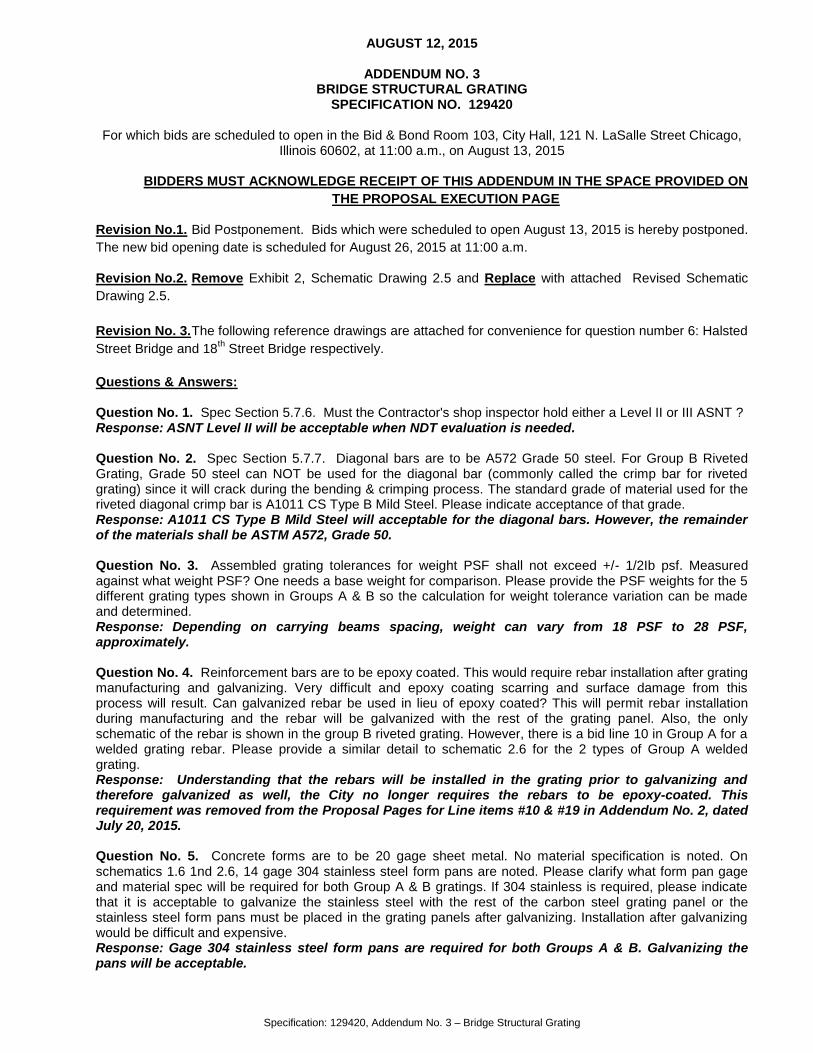
Specification: 129420, Addendum No. 3 – Bridge Structural Grating AUGUST 12, 2015 ADDENDUM NO. 3 BRIDGE STRUCTURAL GRATING SPECIFICATION NO. 129420 For which bids are scheduled to open in the Bid & Bond Room 103, City Hall, 121 N. LaSalle Street Chicago, Illinois 60602, at 11:00 a.m., on August 13, 2015 BIDDERS MUST ACKNOWLEDGE RECEIPT OF THIS ADDENDUM IN THE SPACE PROVIDED ON THE PROPOSAL EXECUTION PAGE Revision No.1. Bid Postponement. Bids which were scheduled to open August 13, 2015 is hereby postponed. The new bid opening date is scheduled for August 26, 2015 at 11:00 a.m. Revision No.2. Remove Exhibit 2, Schematic Drawing 2.5 and Replace with attached Revised Schematic Drawing 2.5. Revision No. 3. The following reference drawings are attached for convenience for question number 6: Halsted Street Bridge and 18 th Street Bridge respectively. Questions & Answers: Question No. 1. Spec Section 5.7.6. Must the Contractor's shop inspector hold either a Level II or III ASNT ? Response: ASNT Level II will be acceptable when NDT evaluation is needed. Question No. 2. Spec Section 5.7.7. Diagonal bars are to be A572 Grade 50 steel. For Group B Riveted Grating, Grade 50 steel can NOT be used for the diagonal bar (commonly called the crimp bar for riveted grating) since it will crack during the bending & crimping process. The standard grade of material used for the riveted diagonal crimp bar is A1011 CS Type B Mild Steel. Please indicate acceptance of that grade. Response: A1011 CS Type B Mild Steel will acceptable for the diagonal bars. However, the remainder of the materials shall be ASTM A572, Grade 50. Question No. 3. Assembled grating tolerances for weight PSF shall not exceed +/- 1/2Ib psf. Measured against what weight PSF? One needs a base weight for comparison. Please provide the PSF weights for the 5 different grating types shown in Groups A & B so the calculation for weight tolerance variation can be made and determined. Response: Depending on carrying beams spacing, weight can vary from 18 PSF to 28 PSF, approximately. Question No. 4. Reinforcement bars are to be epoxy coated. This would require rebar installation after grating manufacturing and galvanizing. Very difficult and epoxy coating scarring and surface damage from this process will result. Can galvanized rebar be used in lieu of epoxy coated? This will permit rebar installation during manufacturing and the rebar will be galvanized with the rest of the grating panel. Also, the only schematic of the rebar is shown in the group B riveted grating. However, there is a bid line 10 in Group A for a welded grating rebar. Please provide a similar detail to schematic 2.6 for the 2 types of Group A welded grating. Response: Understanding that the rebars will be installed in the grating prior to galvanizing and therefore galvanized as well, the City no longer requires the rebars to be epoxy-coated. This requirement was removed from the Proposal Pages for Line items #10 & #19 in Addendum No. 2, dated July 20, 2015. Question No. 5. Concrete forms are to be 20 gage sheet metal. No material specification is noted. On schematics 1.6 1nd 2.6, 14 gage 304 stainless steel form pans are noted. Please clarify what form pan gage and material spec will be required for both Group A & B gratings. If 304 stainless is required, please indicate that it is acceptable to galvanize the stainless steel with the rest of the carbon steel grating panel or the stainless steel form pans must be placed in the grating panels after galvanizing. Installation after galvanizing would be difficult and expensive. Response: Gage 304 stainless steel form pans are required for both Groups A & B. Galvanizing the pans will be acceptable.

Welcome message from author
This document is posted to help you gain knowledge. Please leave a comment to let me know what you think about it! Share it to your friends and learn new things together.
Transcript
Specification: 129420, Addendum No. 3 – Bridge Structural Grating
AUGUST 12, 2015
ADDENDUM NO. 3 BRIDGE STRUCTURAL GRATING
SPECIFICATION NO. 129420
For which bids are scheduled to open in the Bid & Bond Room 103, City Hall, 121 N. LaSalle Street Chicago, Illinois 60602, at 11:00 a.m., on August 13, 2015
BIDDERS MUST ACKNOWLEDGE RECEIPT OF THIS ADDENDUM IN THE SPACE PROVIDED ON
THE PROPOSAL EXECUTION PAGE
Revision No.1. Bid Postponement. Bids which were scheduled to open August 13, 2015 is hereby postponed.
The new bid opening date is scheduled for August 26, 2015 at 11:00 a.m.
Revision No.2. Remove Exhibit 2, Schematic Drawing 2.5 and Replace with attached Revised Schematic
Drawing 2.5.
Revision No. 3. The following reference drawings are attached for convenience for question number 6: Halsted
Street Bridge and 18th Street Bridge respectively.
Questions & Answers: Question No. 1. Spec Section 5.7.6. Must the Contractor's shop inspector hold either a Level II or III ASNT ? Response: ASNT Level II will be acceptable when NDT evaluation is needed. Question No. 2. Spec Section 5.7.7. Diagonal bars are to be A572 Grade 50 steel. For Group B Riveted Grating, Grade 50 steel can NOT be used for the diagonal bar (commonly called the crimp bar for riveted grating) since it will crack during the bending & crimping process. The standard grade of material used for the riveted diagonal crimp bar is A1011 CS Type B Mild Steel. Please indicate acceptance of that grade. Response: A1011 CS Type B Mild Steel will acceptable for the diagonal bars. However, the remainder of the materials shall be ASTM A572, Grade 50. Question No. 3. Assembled grating tolerances for weight PSF shall not exceed +/- 1/2Ib psf. Measured against what weight PSF? One needs a base weight for comparison. Please provide the PSF weights for the 5 different grating types shown in Groups A & B so the calculation for weight tolerance variation can be made and determined. Response: Depending on carrying beams spacing, weight can vary from 18 PSF to 28 PSF, approximately. Question No. 4. Reinforcement bars are to be epoxy coated. This would require rebar installation after grating manufacturing and galvanizing. Very difficult and epoxy coating scarring and surface damage from this process will result. Can galvanized rebar be used in lieu of epoxy coated? This will permit rebar installation during manufacturing and the rebar will be galvanized with the rest of the grating panel. Also, the only schematic of the rebar is shown in the group B riveted grating. However, there is a bid line 10 in Group A for a welded grating rebar. Please provide a similar detail to schematic 2.6 for the 2 types of Group A welded grating. Response: Understanding that the rebars will be installed in the grating prior to galvanizing and therefore galvanized as well, the City no longer requires the rebars to be epoxy-coated. This requirement was removed from the Proposal Pages for Line items #10 & #19 in Addendum No. 2, dated July 20, 2015. Question No. 5. Concrete forms are to be 20 gage sheet metal. No material specification is noted. On schematics 1.6 1nd 2.6, 14 gage 304 stainless steel form pans are noted. Please clarify what form pan gage and material spec will be required for both Group A & B gratings. If 304 stainless is required, please indicate that it is acceptable to galvanize the stainless steel with the rest of the carbon steel grating panel or the stainless steel form pans must be placed in the grating panels after galvanizing. Installation after galvanizing would be difficult and expensive. Response: Gage 304 stainless steel form pans are required for both Groups A & B. Galvanizing the pans will be acceptable.

Specification: 129420, Addendum No. 3 – Bridge Structural Grating
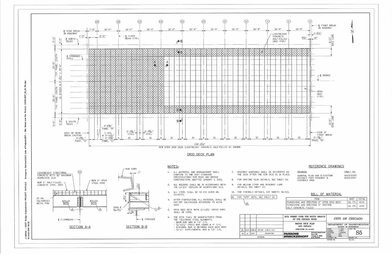
Question No. 6. Schematic 1.3. There is no method of attachment shown for the 3/8x7" bolt down plate to the bottom of the grating main beams. Therefore, does this plate ship loose? If not and attached, please provide detail indicating weld size, length, location and frequency. Also, this plate will require holes for bolting. Please provide, number, location and spacing of these holes for both welded grating shown in schematics 1.1 & 1.2. Response: The plate does not ship loose and shall be attached to the grating. Welding or any other method of attachment will be acceptable, provided that it is structurally sound. It is anticipated that each bridge project will require the design and fabrication of custom panels. The design of the panels will be governed by the bridge specific configuration. The numbers, location and frequency of bolts will be determined by the design, actual field conditions and grating bars spacing. See attached examples from the North Halsted Street and 18th Street bridge rehabilitation projects that show custom panels and bolts layouts. Typical bolt spacing is in the order of 1’-3”, and spacing is alternate. Question No. 7. Schematic 2.4. Similar information for the riveted grating hold down plates is required for the holes in the hold down plates for the three types of riveted grating shown on schematics 2.1, 2.2 & 2.3. Response: See response to Question 6. Question No. 8. Schematics 1.4 & 2.5. These drawings show end banding/ end trim bars for both welded and riveted gratings. The weld of the trim bar to the main beams in the welded grating (1.4) is significantly more than the amount of weld required for the same condition/detail for the riveted grating (2.5). Shouldn't the amount of weld for the same detail be similar for both styles of grating? In 2.5, there is no detail of welding the band bar to the horizontal bearing angle leg for the riveted grating on 2.2. Please provide this detail or information unless there is no weld required. Response: The same amount of weld shall be expected for the riveted grating as for the welded grating. See attached revised schematic 2.5. Question No. 9. Schematics 1.3 & 1.5. These two drawings show details of the pipe sleeves to be installed in the two welded grating designs. It is noted that there is no similar detail provided for the riveted gratings. Therefore, are there no pipe sleeves required for the 3 riveted grating designs as with the welded grating? If they are required, please provide details and add corresponding lines items to the Group B bid document.
Response: No pipe sleeves are required for the riveted grating.
Question No. 10. Schematic 2.6. This drawing shows details of a partially concrete filled riveted bearing angle grating. Is this the only style of the three types of riveted grating (shown in 2.1, 2.2 & 2.3) that could be filled with concrete? If not, please provide corresponding details for the riveted grating in 2.1 & 2.3. Please note that the riveted grating in 2.3 does not have transverse bars in which to hold rebars. Might any of these three riveted grating be filled full depth with concrete. If so, please provide appropriate details including rebar size and locations or spacing. Schematic 2.6 indicates rebars are #3. RFQ line item 19 indicates #5. The larger rebar is typical of a full-depth concrete pour. #3 rebar would normally be used on a half-depth installation. Please confirm which size or sizes are required? Response: In the eventuality of rebar usage, #3 will be required for half-depth concrete pour and #5 will be required for full depth concrete pour, for both welded and riveted grating. It is anticipated that each bridge project will require the design and fabrication of custom panels. Therefore, location, frequency and spacing will be determined by design. Question No. 11. RFQ Line Item 10. This line item calls for #5 rebar in the welded grid designs. No rebar appear on any of the welded grating schematics. Please provide details of rebar locations & frequency or spacing of these rebar for the two welded grating designs. If 3# rebars are to be used in the riveted gratings, wouldn't # 3 be adequate for the welded gratings also?
Response: See response to Question No. 10.
ANY AND ALL ADDENDA MUST BE ACKNOWLEDGED BY THE VENDOR ON THE EXECUTION PAGE BY ADDENDUM NUMBER. FAILURE ON BEHALF OF THE VENDOR MAY BE CAUSE FOR REJECTION
OF BID.
ALL REVISIONS INSCRIBED HEREIN WILL BE INCORPORATED INTO THE BID SPECIFICATION PER ADDENDUM NO. 3
END OF ADDENDUM NO. 3
CITY OF CHICAGO JAMIE L. RHEE DEPARTMENT OF PROCUREMENT SERVICES CHIEF PROCUREMENT OFFICER


Related Documents