Passion.Technology.Design. EN Audio/video module for Simplebus2 Ultra Art. UT2020 Simplebus2 Ultra remote camera audio module Art. UT2010VC TECHNICAL MANUAL

Welcome message from author
This document is posted to help you gain knowledge. Please leave a comment to let me know what you think about it! Share it to your friends and learn new things together.
Transcript

Passion.Technology.Design.
EN
Audio/video module for Simplebus2 Ultra Art. UT2020
Simplebus2 Ultra remote camera audio module Art. UT2010VC
TECHNICAL MANUAL

2
Warning
Intended use
This Comelit product has been designed and manufactured for use in the creation of audio and video communication systems in residential, commercial, industrial and public buildings.
Installation
All activities connected to the installation of Comelit products must be carried out by qualified technical personnel, with careful observation of the indications provided in the Manuals / Instruction sheets supplied with those products.
Wires
Disconnect the power supply before carrying out any operations on the wiring.
Use wires with a cross-section suited to the distances involved, observing the instructions provided in the system manual.
We advise against running the system wires through the same duct as power cables (230V or higher).
Safe usage
To ensure Comelit products are used safely:
• carefully observe the indications provided in the Manuals / Instruction sheets,
• make sure the system created using Comelit products has not been tampered with / damaged.
Service
Comelit products do not require maintenance aside from routine cleaning, which should be carried out in accordance with the indications provided in the Manuals / Instruction sheets.
Any repairs must be carried out:
• for the products themselves, exclusively by Comelit Group S.p.A.,
• for the systems, by qualified technical personnel.
Disclaimer
Comelit Group S.p.A. does not assume any responsibility for
• any purpose other than the intended use,
• failure to observe the indications and warnings contained in this Manual / Instruction sheet.
Comelit Group S.p.A. reserves the right to change the information provided in this Manual / Instruction Sheet at any time and without prior notice.

3
Table of contentsWarning ............................................................................................ 2
Description ....................................................................................... 4UT2020 ......................................................................................................4
UT2010VC .................................................................................................4
Installation notes (Art. UT2020) ...................................................... 6
Technical specifications ................................................................. 7Art. UT2020 ...............................................................................................7
Art. UT2010VC ..........................................................................................8
Installation ........................................................................................ 9Flush-mounted installation composition table ....................................9
Surface-mounted installation composition table ................................9
Flush-mounted installation ........................................................... 10Removing nameplates (2A) / module (2B) ............................................11
Installation with side-by-side boxes .....................................................12
Wall-mounted installation ............................................................. 13
Optional .......................................................................................... 13Removing nameplates (2A) / module (2B) ............................................14
Installation with side-by-side boxes .....................................................15
Connections ................................................................................... 16Connections for Art. UT2020, UT2010VC .............................................16
UT2020, UT2010VC connections with separate power supply ..........16
Variants ...................................................................................................16
Remote camera connection (Art. UT2010VC only) ..............................17
Module connection ........................................................................ 18Outdoor entrance panel module consumption table .........................18
powered by Art. 1210/1210A ............................................................18
powered by additional power supply unit Art. 1595 .........................18
Connection of button modules Art. UT9200 .....................................19
Connection of Touchscreen module Art. UT9270 .............................19
Connection of number keypad module Art. UT9279M .....................19
Variant with separate power supply ..................................................19
Programming ................................................................................. 20Configuring the button type to maintain during normal operation
(single/dual) ............................................................................................20
Address button modules .......................................................................20
Program call addresses .........................................................................20
Smart programming of consecutive addresses ......................... 21
Programming of specific addresses ............................................ 22
Special programming via DIP Switch .......................................... 23Special programming table ...................................................................24
Twilight sensor ............................................................................... 26Camera LED lighting and button backlighting management .............26
Checking twilight sensor operation .....................................................27
Adjusting the brightness of the button LEDs and the camera light ..28
Light-me function .......................................................................... 29Light-me function behaviour on the basis of the LED backlighting
mode........................................................................................................29
Replacing the audio/video module with programming restore backup ............................................................................................ 30
Configuring via PC......................................................................... 31
Errors and indications ................................................................... 31
System performance and layouts ................................................ 31
Addressing table ............................................................................ 32

4
UT2020Audio/video module for Ultra entrance panel, Simplebus2 system. For use in systems with power supply unit art. 1210 / 1210A.
Wide-angle colour video camera (field of vision: 120° horizontal, 90° vertical)
UT2010VCAudio module designed for connection of an analogue remote camera with PAL standard for Ultra entrance panel, Simplebus2 system. For use in systems with power supply unit art. 1210 / 1210A.
Easy to install and simple to configure, thanks to the smart programming of call buttons.
Twilight sensor for automatic nameplate backlighting switch-off during daylight hours.
Omnidirectional digital microphone and double loudspeaker for high-fidelity audio.
Audio-visual indications for disabled individuals assistance request can be activated via programming.
Facility for 2 call buttons. To be finished with cap, single button or dual button made using aluminium or professional grade plastic treated to prevent yellowing and dulling.
Adjustment and programming can take place without removing the module.
Dimensions: 100 x 90 x 35 mm.
ULTRA: the new and most technologically advanced entrance panel offering maximum ease of installation.
Available in flush-mounted (10 mm protrusion from the wall) or surface-mounted (just 35 mm protrusion from the wall) variants.
Description

5
12
UPArt. UT2010VC19.
UP
14. 15. 16.3. 4. 5. 6. 7.
10.11.12.13. 9.
1. 2. 2.
8. 17.18.
1. Indicator LEDs
call sent (green) / system busy (red)
lock-release enabled
communication enabled
2. Loudspeakers
3. Colour video camera (with Art. UT2020 only)
4. Speaker volume control
5. S1 Button programming selector
6. S2 Special programming selector
7. Micro USB input for programming via computer
8. Jumper for power supply management (remove in case of separate power supply)
9. Twilight sensor
10. Addressing and programming Dip Switches
11. Microphone volume control
12. Programming confirmation button
13. Digital microphone
Use screwdriver supplied
14. Terminal block for connection:
RTE programmable RTE (local lock-release input) or DO input (door open indication)
GND SE- RTE and door lock input reference negative
SE+ electric door lock connectionNO NC COM relay contacts
V- V+ power supplyLL bus line connection
15. Ethernet terminal block, only for use in case of additional modules with LAN
16. Connector for additional modules with LAN
17. 18. Connector for additional module connection
19. Remote camera connection (with Art. UT2010VC only):
in flush-mounted installations, use the terminal;
in surface-mounted installations, solder the wires and use the heat-shrink sheath.

6
165
cm
100
cm
215
cm
90°
50 cm
100
cm
180
cm
130
cm
90°
50 cm
150
cm
100
cm
200
cm
90°
50 cm
50 c
m
175 cm
120°
Installation notes (Art. UT2020)
The camera must not be installed in front of light sources, or in places where the filmed subject is against the light. In dim environments, we recommend additional lighting is provided.

7
Technical specifications
Art. UT2020
GENERAL DATAType Modular
Product height (mm) 90Product width (mm) 100Product depth (mm) 35
Product colour Black RAL9005, Transparent, AluminiumProduct weight (g) 350
Material Polycarbonate, Aluminium alloyFlush mounting Yes, with specific accessory
Surface mounting Yes, with specific accessoryCOMPATIBLE SYSTEMS
Simplebus2 audio/video with power supply unit Art. 1210/1210A Yes
AUDIO SPECIFICATIONSMicrophone MEMS digital audio sensor, omnidirectional
Loudspeaker 28 mm (Ø), 8 Ohm, 1W (2)Technologies implemented Full-Duplex
CAMERA FEATURESCamera Colour
Sensor type 1/3" CMOSLens (mm) 1.79
Viewing angle (H x V - °) 120 x 90Sensitivity (lux) 0.45
Resolution (H x V - pixel) 1288 x 968ELECTRICAL SPECIFICATIONS
Type of power supply Power supply via video entry busPower supply voltage 33 VDC
Absorption in standby (W) 1.5Maximum absorption (W) 6
HARDWARE CHARACTERISTICSCall type Buttons
Type of buttons MechanicalNumber of buttons (no.) 2
Backlighting colour White, OffTerminals L L V+ V- COM NC NO SE+ SE-/GND RTE TX- TX+ RX- RX+
Number of inputs (no.) 1Number of outputs (no.) 2
Output type Relay (C-NO-NC, 4A@12-24 VAC/VDC, inrush current 10A)Communication port Micro-USB
Twilight sensor YesSETTINGS
Loudspeaker volume YesMic volume Yes
Backlighting brightness YesPROGRAMMING MODE
Manual (by means of Dip Switches) YesViP Manager software Yes
ENVIRONMENTAL AND CONFORMITY SPECIFICATIONS
IP protection rating (when installed) IP65IK anti-vandal protection rating IK08
Operating temperature (°C) -25 to 55Operating humidity (max RH - %) 25 to 95
Environmental class IV
Conformity and Certifications RoHS II - 2011/65/EU (EN 50581:2012), EMC 2014/30/EU (EN 61000-6-1:2007, EN 61000-6-3:2007+A1:2011)
MAIN FUNCTIONSLock-release Yes
Number of auxiliary relays (no.) 1Input for local key button Yes
Input for door open signal YesSystem status visual indications YesSystem status audio indications Yes
System status voice synthesis Yes

8
Art. UT2010VC
GENERAL DATAType Modular
Product height (mm) 90Product width (mm) 100Product depth (mm) 35
Product colour Black RAL9005, Transparent, AluminiumProduct weight (g) 265
Material Polycarbonate, Aluminium alloyFlush mounting Yes, with specific accessory
Surface mounting Yes, with specific accessory
COMPATIBLE SYSTEMSSimplebus2 audio/video with power supply
unit Art. 1210/1210A Yes
AUDIO SPECIFICATIONSMicrophone MEMS digital audio sensor, omnidirectional
Loudspeaker 28 mm (Ø), 8 Ohm, 1W (2)
ELECTRICAL SPECIFICATIONSType of power supply Power supply via video entry busPower supply voltage 33 VDC
Absorption in standby (W) 1.5Maximum absorption (W) 4
HARDWARE CHARACTERISTICSCall type Buttons
Type of buttons MechanicalNumber of buttons (no.) 2
Backlighting colour White, OffTerminals L L V+ V- COM NC NO SE+ SE-/GND RTE TX- TX+ RX- RX+
Number of inputs (no.) 1Number of outputs (no.) 2
Output type Relay (C-NO-NC, 4A@12-24 VAC/VDC, inrush current 10A)Communication port Micro-USB
Twilight sensor Yes
SETTINGSLoudspeaker volume Yes
Mic volume YesBacklighting brightness Yes
PROGRAMMING MODEManual (by means of Dip Switches) Yes
ViP Manager software Yes
ENVIRONMENTAL AND CONFORMITY SPECIFICATIONS
IP protection rating (when installed) IP65IK anti-vandal protection rating IK08
Operating temperature (°C) -25 to 55Operating humidity (max RH - %) 25 to 95
Environmental class IV
Conformity and Certifications RoHS II - 2011/65/EU (EN 50581:2012), EMC 2014/30/EU (EN 61000-6-1:2007, EN 61000-6-3:2007+A1:2011)
MAIN FUNCTIONSLock-release Yes
Number of auxiliary relays (no.) 1Input for local key button Yes
Input for door open signal YesSystem status visual indications YesSystem status audio indications Yes
System status voice synthesis Yes

9
InstallationFl
ush-
mou
nted
box
3110/1
3110/1A
3110/2
3110/2A
3110/3
3110/3A
3110/4
3110/4A
Rai
n sh
ield
UT9181
UT9182
UT9184H
UT9183
UT9186
UT9189
UT9184
UT9188
Mod
ule
hold
er/
finis
hing
fram
e
UT9161
UT9162
UT9163
UT9164
Rai
n sh
ield
UT9191
UT9192
UT9194H
UT9193
UT9196
UT9199
UT9194
UT9198
Hou
sing
/fra
me
UT9171
UT9172
UT9174H
UT9173
UT9176
UT9179
UT9174
UT9178
Optional
The entrance panel is available in flush-mounted or surface-mounted variants:
Flush-mounted installation composition table
Surface-mounted installation composition table
A = Rain shield
B = Surface-mounted housing with frame
A = Flush-mounted box
B = Rain shield
C = Flush-mounted module holder with finishing frame

10
2
1
2
UP
53 4
1
Flush-mounted installation
Optional
BLACK
Optional
RED

11
6
1
A
B
CC
2
+ Art. UT9110
MAX 0,2 mm
MAX 0,2 mm
9
2
1
11 12
1
2
10
CLACK!
CLACK!
1
2
3 CLACK!
8
CLACK!
CLACK!
CLACK!
1
2
3
7
1
2
3
12
31
2A
1
3
2
4
2B
Removing nameplates (2A) / module (2B)
CLOSE
The button has a nameplate which can be written on (A); alternatively, an adhesive label can be applied (B).
The total thickness of the nameplate + adhesive label must not exceed 0.2 mm.
You can visit the website pro.comelitgroup.com to download the PDF to print the entrance panel name cards, using the pre-cut sheets (C) available in our catalogue (Art. UT9110 ).
Custom engraved Full Metal Ultra nameplates are available on request. Find out how: https://pro.comelitgroup.com/customised-nameplates-for-ultra-entrance-panel
Kit Art. UT9110 contains 5 sheets of pre-cut labels for nameplates and 1 sheet for the information module.
The sheets are made using Yupo paper which offers the ultimate transparency and resistance to atmospheric agents over time.
To print the labels, use the editable .pdf file which is available to download free of charge from the website pro.comelitgroup.com

12
Installation with side-by-side boxes
Before installing the boxes in the wall, fit the spacers.

13
2
UP
53 4
UP
1
2
3
1
Wall-mounted installation
Optional
BLACK
RED
Optional

14
6
1
A
B
CC
2
+ Art. UT9110
MAX 0,2 mm
MAX 0,2 mm
9
2
1
11 12
1
2
10
CLACK!
CLACK!
1
2
CLACK!3
8
CLACK!
CLACK!
1
2
CLACK!3
7
1
2
3
12
1
3
2A
1
3
2
4
2B
Removing nameplates (2A) / module (2B)
CLOSE
The button has a nameplate which can be written on (A); alternatively, an adhesive label can be applied (B).
The total thickness of the nameplate + adhesive label must not exceed 0.2 mm.
You can visit the website pro.comelitgroup.com to download the PDF to print the entrance panel name cards, using the pre-cut sheets (C) available in our catalogue (Art. UT9110 ).
Custom engraved Full Metal Ultra nameplates are available on request. Find out how: https://pro.comelitgroup.com/customised-nameplates-for-ultra-entrance-panel
Kit Art. UT9110 contains 5 sheets of pre-cut labels for nameplates and 1 sheet for the information module.
The sheets are made using Yupo paper which offers the ultimate transparency and resistance to atmospheric agents over time.
To print the labels, use the editable .pdf file which is available to download free of charge from the website pro.comelitgroup.com
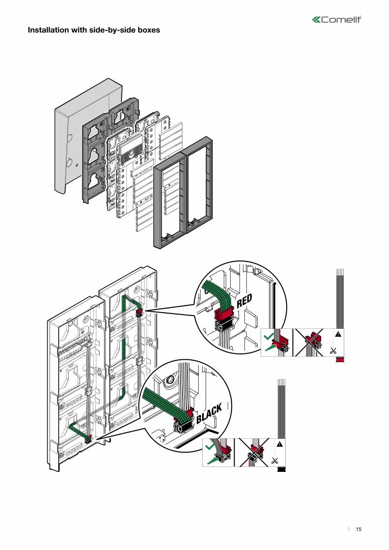
15
Installation with side-by-side boxes

16
1210A1210
UT2020UT2010VC
ETR GND
SE-SE+
NO NCCOM
LL+VV
-
- +
120-230 V
15951210A1210
ETR GND
SE-SE+
NO NCCOM
LL+VV
-
UT2020UT2010VC
J4J4
ETR GND
SE-SE+ NO NC
COM
LL+VV
-
1210A12104A MAX
AC-DC12V/24V
UT2020UT2010VC
4A MAXAC-DC
12V/24V UT2020UT2010VC
ETR GND
SE-SE+ NO NC
COM
LL+VV
-
1210A1210
ON
1 2 3 4 6 75 8
ConnectionsConnections for Art. UT2020, UT2010VC
UT2020, UT2010VC connections with separate power supply
Max 20 m. Local door-opener button.
Max 20 m. Local door-opener button.
“C.NC.NO relay activation on actuator command: 2 sec”
f Set DIP switch 8 to ON permanently (as shown in the figure) Max 20 m. Local door-opener button.
Variants
Variant for using the outdoor entrance panel relay Variant for using a safety door lock

17
1210A1210
UT2010VC
ETR GND
SE-SE+
NO NCCOM
LL+VV
-
UP
RED
BLACK
V
S
~
SV
SV
RED BLACK
Remote camera connection (Art. UT2010VC only)
Max 20 m. Local door-opener button.

18
Module connection
On systems with Art. UT2020/UT2010VC and power supply unit Art. 1210/1210A, the maximum current available for the outdoor entrance panel modules is 100 mA.
Calculate the total power consumption of the modules in your system configuration using the Consumption table.
If the total power consumption exceeds 100 mA, connect a supplementary power supply unit (Art. 1595) to the V+ and V- contacts of the outdoor entrance panel, as shown in the figure below (see “UT2020, UT2010VC connections with power supply”). In any case, the total absorption must be lower than 500 mA.
Outdoor entrance panel module consumption table
Code Consumption (mA)
UT9200 Call button modules 12.5
UT9240 Information module 12.5
UT9240M Metal information module 12.5
UT9279M Number keypad module
40 With SE output active
75 With 1 bistable relay active
100 With 2 bistable relays active at the same time
UT9310M Magnetic induction module 245 Always needs to be powered by additional power supply unit Art. 1595
UT9270 Touchscreen module 100
In systems with an outdoor entrance panel consisting of 1 audio or audio/video module, Touch module art. UT9270 and up to 80 users, it is not necessary to provide any additional power supply.
For all other combinations, provide an additional power supply unit art. 1595
UP
LL
UP
LL
V+V- J4
powered by Art. 1210/1210AA B powered by additional power supply unit Art. 1595

19
UP
BLACK
REDMAX 8
1210A1210
UT2020UT2010VC
UT9200
ETR GND
SE-SE+
NO NCCOM
LL+VV
-
1210A1210
UT2020UT2010VC
UT9270
ETR GND
SE-SE+
NO NCCOM
LL+VV
-
- +
120-230 V
1595
1210A1210
ETR GND
SE-SE+
NO NCCOM
LL+VV
-
UT2020UT2010VC
J4
UT9270
Maximum 80 users > 80 users
1210A1210
UT2020UT2010VC
UT9279M
ETR GND
SE-SE+
NO NCCOM
LL+VV
-
Connection of button modules Art. UT9200
Connection of Touchscreen module Art. UT9270 Variant with separate power supply
Connection of number keypad module Art. UT9279M
Max 20 m. Local door-opener button. Max 8 modules (Max 30 modules with additional power supply).
Max 20 m. Local door-opener button. For systems with over 80 users, provide an additional power supply
Max 20 m. Local door-opener button.
20
65 default 65
ON
OFF
1
ON
2 3 4 65
8765 8765default
ON
OFF
1
ON
2 3 4 65
ON
1 2 3 4 65
ON
1 2 3 4 65
ON
1 2 3 4 65
ON
1 2 3 4 65
ON
1 2 3 4 65
1
2
4
3
5
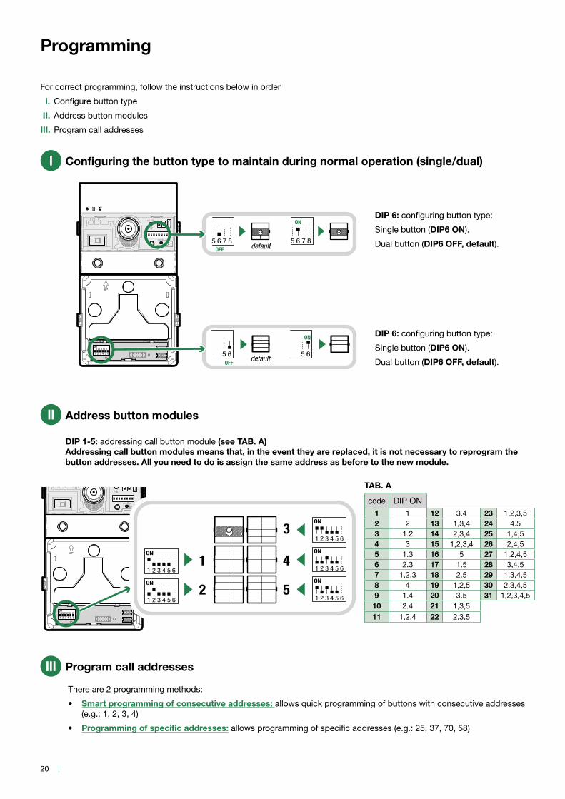
Programming
For correct programming, follow the instructions below in order
I. Configure button type
II. Address button modules
III. Program call addresses
code DIP ON1 1 12 3.4 23 1,2,3,52 2 13 1,3,4 24 4.53 1.2 14 2,3,4 25 1,4,54 3 15 1,2,3,4 26 2,4,55 1.3 16 5 27 1,2,4,56 2.3 17 1.5 28 3,4,57 1,2,3 18 2.5 29 1,3,4,58 4 19 1,2,5 30 2,3,4,59 1.4 20 3.5 31 1,2,3,4,5
10 2.4 21 1,3,511 1,2,4 22 2,3,5
TAB. A
Configuring the button type to maintain during normal operation (single/dual)
DIP 6: configuring button type:
Single button (DIP6 ON).
Dual button (DIP6 OFF, default).
I
Address button modules
DIP 1-5: addressing call button module (see TAB. A) Addressing call button modules means that, in the event they are replaced, it is not necessary to reprogram the button addresses. All you need to do is assign the same address as before to the new module.
II
Program call addresses
There are 2 programming methods:
• Smart programming of consecutive addresses: allows quick programming of buttons with consecutive addresses (e.g.: 1, 2, 3, 4)
• Programming of specific addresses: allows programming of specific addresses (e.g.: 25, 37, 70, 58)
III
DIP 6: configuring button type:
Single button (DIP6 ON).
Dual button (DIP6 OFF, default).

21
LL
1
S1 S2
8
8765 defaultOFF
8765
ON
9
DIP 6: configuring button type: Single button (DIP6 ON).Dual button (DIP6 OFF, default).
Smart programming of consecutive addresses
OFF
ON
1 2 3 4 6 75 8
4
S1 S2
3
ON
1 2 3 4 6 75 8
5
example: code 1
Set the address of the apartment you wish to call (for example: 1) using the DIP-switches (see “Addressing table” )
8765 defaultOFF
8765
ON
2
DIP 6: configuring button type: Single button (DIP6 ON).Dual button (DIP6 OFF, default).
= 1
6
= 2+1= 3+1 = 4+1
= 5+1
7
Press the button you want to associate with the call address set using the DIP-switches
Press the following buttons to assign consecutive addresses.

22
LL
1
8765 defaultOFF
8765
ON
2
DIP 6: configuring button type: Single button (DIP6 ON).Dual button (DIP6 OFF, default).
OFF
ON
1 2 3 4 6 75 8
4
S1 S2
3
ON
1 2 3 4 6 75 8
5
example: code 25
Set the address of the apartment you wish to call (for example: 25) using the DIP-switches (see “Addressing table” )
S1 S2
8
8765 defaultOFF
8765
ON
9
DIP 6: configuring button type: Single button (DIP6 ON).Dual button (DIP6 OFF, default).
Programming of specific addresses
= 25
6
ON
1 2 3 4 6 75 8
ON
1 2 3 4 6 75 8
ON
1 2 3 4 6 75 8
3770 58
7
Press the button you want to associate with the call address set using the DIP-switches
Repeat steps 4 and 5 to assign a specific address to each button
example: code 37 example: code 70 example: code 58

23
Special programming via DIP Switch
OFF
ON
1 2 3 4 6 75 8
2
1
4 5
1. Set the dip switches in accordance with the function you wish to program (see “Special programming table”).
2. Press the confirm button.
7Reset the configuration of the DIP-switches
S1 S2
6
LL
1 2Take note of the DIP-switch settings
S1 S2
3

24
CODE DIP SWITCHES ON FUNCTIONS
Audio-visual messages195 1,2,7,8 Hebrew196 3,7,8 Polish 197 1,3,7,8 Catalan198 2,3,7,8 Galician199 1,2,3,7,8 Basque206 2,3,4,7,8 Danish207 1,2,3,4,7.8 Norwegian211 1,2,5,7,8 Swedish215 1,2,3,5,7.8 Italian216 4,5,7,8 French217 1,4,5,7,8 Spanish218 2,4,5,7,8 Dutch219 1,2,4,5,7.8 Greek220 3,4,5,7,8 English221 1,3,4,5,7.8 German222 2,3,4,5,7.8 Portuguese
202 2,4,7,8 Enables voice message (door opened warning) when the RTE contact is closed203 1,2,4,7,8 Disables voice message (door opened warning) when the RTE contact is closed (default setting)210 2,5,7,8 Enables visual messages and disables voice messages (default)214 2,3,5,7,8 OFF: disables voice and visual messages
Actuator command management N.B. Art. 1256 in generic actuator mode must not be present in the system.
229 1,3,6,7,8 C.NC.NO relay activation on actuator command: 2 sec (default)230 2,3,6,7,8 C.NC.NO relay activation on actuator command: 4 sec231 1,2,3,6,7.8 C.NC.NO relay activation on actuator command: 8 sec
Door lock184 4,5,6,8 Door lock time: 100 msec185 1,4,5,6,8 Door lock time: 200 msec186 2,4,5,6,8 Door lock time: 500 msec
245 1,3,5,6,7.8 Door lock time: 2 sec + disabling tone (default)246 2,3,5,6,7.8 Door lock time: 4 sec247 1,2,3,5,6,7,8 Door lock time: 8 sec
248 4,5,6,7,8 Door lock confirmation tone: enabled
252 3,4,5,6,7.8 Lock-release always enabled (default)253 1,3,4,5,6,7,8 Lock-release only enabled for user called
System functions232 4,6,7,8 Awaiting response time: 60 sec (default)233 1,4,6,7,8 Awaiting response time: 120 sec234 2,4,6,7,8 Awaiting response time: 30 sec
235 1,2,4,6,7.8 Talk time: 90 sec (default)236 3,4,6,7,8 Talk time: 180 sec
145 1,5,8 RTE input set as local lock-release input (default)146 2,5,8 RTE input set as door open indication
147 1,2,5,8 Self activation time: 60 sec (default)149 1,3,5,8 Self activation time: 30 sec
237 1,3,4,6,7.8 Self activation: enabled (default)238 2,3,4,6,7.8 Self activation: disabled
154 2,4,5,8 System busy signalling time: 10 sec (default)
Special programming table

25
155 1,2,4,5,8 System busy signalling time: 300 sec
239 1,2,3,4,6,7,8 Confirmation tone on user call = enabled (default)240 5,6,7,8 Confirmation tone on user call = disabled
243 1,2,5,6,7.8 Reset wait time (after hang-up or after lock-release): 10 sec (default)244 3,5,6,7,8 Reset wait time (after hang-up or after lock-release): 1 sec
208 5,7,8 Enables “Reset wait time" on lock-release command (default)
209 1,5,7,8 Disables “awaiting reset time" on lock-release command (awaiting response time or talk time will be activated)
249 1,4,5,6,7.8 Send call: single (default)250 2,4,5,6,7.8 Call transmission: triple
Button tones142 2,3,4,8 Button press tone ON (default)143 1,2,3,4,8 Button press tone OFF
Button backlighting management158 2,3,4,5,8 OFF mode: Button LEDs always off159 1,2,3,4,5.8 ON mode: Button LEDs always on160 6.8 AUTO mode: Button LEDs on at night and off during the day, thanks to the twilight sensor (default)
161 1,6,8Enables brightness control for the button LEDs.
f Press a button repeatedly for each module to change the individual brightness of the buttons (see: “Adjusting the brightness of the button LEDs and the camera light”)
162 2,6,8 Light-me OFF (default)
163 1,2,6,8Light-me ON: the button LEDs for the audio/video module are always on and when the button is pressed all button LEDs light up (see: “Light-me function behaviour on the basis of the LED backlighting mode”)
150 2,3,5,8 Light-me time: 30 sec151 1,2,3,5,8 Light-me time: 60 sec (default)152 4,5,8 Light-me time: 120 sec
Camera LED light management on self activation (only with Art. UT2020)166 2,3,6,8 The LED light is always off upon self activation167 1,2,3,6,8 The LED light copies the ON/OFF/AUTO mode set for calls (functions 168/169/170) (default)
Camera LED light management upon calls (only with Art. UT2020)168 4,6,8 OFF mode: LED light always off upon calls169 1,4,6,8 ON mode: LED light always on upon calls170 2,4,6,8 AUTO mode: LED light on at night and off during the day, thanks to the twilight sensor (default)
171 1,2,4,6,8Enables brightness control for the camera LED light.
f Press the programming confirmation button repeatedly to adjust the brightness
Restore backup
114 2,5,6,7 If the audio/video module is replaced, all programming is imported (only available if at least one additional module is connected vi flat cable)
Reset
115 1,2,5,6,7 Reset button programming: if the modules are addressed (see “Address button modules”) this resets the programming for the button call addresses
254 2,3,4,5,6,7,8 Reset special programming: restore all the parameters described in this table to their default values

26
2
1ON
1 2 3 4 6 75 8
LL
1
5
OFF
ON
1 2 3 4 6 75 8
4
S1 S2
3
2Take note of the DIP-switch settings
Twilight sensor
Camera LED lighting and button backlighting management
The twilight sensor is in AUTO mode by default: the camera and button LEDs light up at night and switch off during the day. To change the setting to ON (LEDs always on) or OFF (LEDs always off), proceed as follows:
NOTE: when the OFF and AUTO lighting modes are active, every time the entrance panel is powered, the buttons light up for the duration of the start-up phase (10 seconds maximum).
In AUTO mode the twilight sensor checks the ambient light level every 9 minutes; if the measured values exceed the specified minimum/maximum thresholds, it is activated/deactivated accordingly.
OFF ON AUTO (default)
ON
1 2 3 4 6 75 8
cod. 168
ON
1 2 3 4 6 75 8
cod. 169
ON
1 2 3 4 6 75 8
cod. 170
OFF ON AUTO (default)
ON
1 2 3 4 6 75 8
cod. 158 cod. 159
ON
1 2 3 4 6 75 8
ON
1 2 3 4 6 75 8
cod. 160
1. Set the desired mode for the camera (A) or button (B) LEDs 2. Press the confirm button
example: code 159
Cam
era
LED
Butto
n LE
Ds

27
2
S1 S2
1
S1 S2
3
S1 S2
6
5 sec
Checking twilight sensor operation
If it is daytime and you want to check AUTO mode operation for the twilight sensor, you can proceed as follows:
1. Enter programming mode
2. Block the twilight sensor for 5 seconds
» If AUTO mode has been set, the camera and button LEDs will come on.
3. Exit programming
7Reset the configuration of the DIP-switches

28
LL
1
S1 S2
3
Adjusting the brightness of the button LEDs and the camera light
2Take note of the DIP-switch settings
6A Adjusting the camera light brightness
Press the programming confirmation button repeatedly to adjust the camera light brightness level
OFF
ON
1 2 3 4 6 75 8
2
cod. 161
cod. 171 ON
1 2 3 4 6 75 8
1ON
1 2 3 4 6 75 84 5
1. Enable brightness control
(A) for the camera light (code 171) or (B) for the buttons (code 161)
2. Set the desired function (code 171/161) and press the confirm programming button
6B Adjusting the button brightness
Press a button repeatedly for each module to change the individual brightness level of the buttons

29
S1 S2
7 8Reset the configuration of the DIP-switches
BUTTON BACKLIGHTING
With Light-Me function enabled
[code 163]
OFF mode
[code 158]
ON mode
[code 159]
AUTO mode
[code 160]
Light-me function behaviour on the basis of the LED backlighting mode
Thanks to this function, button backlighting is only enabled on the user’s request, by pressing the LIGHT-ME button on the audio/video module; this saves energy and reduces light pollution.
Backlighting management for this button depends on the twilight sensor setting. It is in AUTO mode by default: the LEDs light up at night and switch off during the day. It can be set to ON (LEDs always on) or OFF (LEDs always off).
Light-me function

30
2
1
3
45
12
ON
1 2 3 4 6 75 8
cod. 114
2
S1 S2
1
3
3
2
S1 S2
1
2
3
5
6
1
2
3
11
2
1
4
Replacing the audio/video module with programming restore backup
If the audio or audio/video module is replaced, the following instructions must be observed. The procedure should be completed within one hour of removal of the old module.
Take note of the DIP-switch settings
1. Enter programming mode by moving S2 DIP-switch upwards
» the red “system busy” LED flashes for the duration of the procedure
2. Set special programming 114 to import all the programming settings
3. Press the confirm programming button
» the green “lock-release” LED will start flashing » at the end of the backup (approx. 30 sec.):
» the green “lock-release” LED switches off » the green “audio enabled” LED comes on for a few
seconds.
1. Exit programming mode by moving the S2 DIP-switch downwards
» the red “system busy” LED switches off
2. Reset the configuration of the DIP-switches
3. Reattach the front panel
NEW
OLD

31
Configuring via PC
System performance and layoutsFor further information regarding system performance and to view installation layouts, click on the system type:
• Simplebus2 audio/video
Errors and indicationsINDICATION SOLUTION
RED LED LIT STEADILY +
DISSUASION TONE
Line short-circuit Check connections
Dual power supply present Remove jumper J4 on the audio/video module
Button modules with the same ID Check the button module IDs
Programming selector positioning error Check the position of selectors S1 and S2 (they cannot both be set to ON)
RED LED FLASHING Device in programming
All device configurations can be performed via PC and ViP Manager configuration software, available to download free of charge from pro.comelitgroup.com (See programming manual).
For example:• programming call addresses for the buttons• activating audiovisual indications• adjusting the backlighting and twilight sensor threshold• setting the functions that can be assigned to the RTE input (lock-release, relay control, actuator control, etc.)• setting activations that can be assigned to the module SE outputs and relay
√ You will need a USB micro-USB cable.

32
* NOTE: Code 240 is reserved for the porter switchboard
Addressing table
Code Dip switch ON
1 1 31 1,2,3,4,5 61 1,3,4,5,6 91 1,2,4,5,7 121 1,4,5,6,7 151 1,2,3,5,8 181 1,3,5,6,8 211 1,2,5,7,8
2 2 32 6 62 2,3,4,5,6 92 3,4,5,7 122 2,4,5,6,7 152 4,5,8 182 2,3,5,6,8 212 3,5,7,8
3 1.2 33 1.6 63 1,2,3,4,5.6 93 1,3,4,5,7 123 1,2,4,5,6.7 153 1,4,5,8 183 1,2,3,5,6.8 213 1,3,5,7,8
4 3 34 2.6 64 7 94 2,3,4,5,7 124 3,4,5,6,7 154 2,4,5,8 184 4,5,6,8 214 2,3,5,7,8
5 1.3 35 1,2,6 65 1.7 95 1,2,3,4,5.7 125 1,3,4,5,6.7 155 1,2,4,5,8 185 1,4,5,6,8 215 1,2,3,5,7.8
6 2.3 36 3.6 66 2.7 96 6.7 126 2,3,4,5,6.7 156 3,4,5,8 186 2,4,5,6,8 216 4,5,7,8
7 1,2,3 37 1,3,6 67 1,2,7 97 1,6,7 127 1,2,3,4,5,6,7 157 1,3,4,5,8 187 1,2,4,5,6.8 217 1,4,5,7,8
8 4 38 2,3,6 68 3.7 98 2,6,7 128 8 158 2,3,4,5,8 188 3,4,5,6,8 218 2,4,5,7,8
9 1.4 39 1,2,3,6 69 1,3,7 99 1,2,6,7 129 1.8 159 1,2,3,4,5.8 189 1,3,4,5,6.8 219 1,2,4,5,7.8
10 2.4 40 4.6 70 2,3,7 100 3,6,7 130 2.8 160 6.8 190 2,3,4,5,6.8 220 3,4,5,7,8
11 1,2,4 41 1,4,6 71 1,2,3,7 101 1,3,6,7 131 1,2,8 161 1,6,8 191 1,2,3,4,5,6,8 221 1,3,4,5,7.8
12 3.4 42 2,4,6 72 4.7 102 2,3,6,7 132 3.8 162 2,6,8 192 7.8 222 2,3,4,5,7.8
13 1,3,4 43 1,2,4,6 73 1,4,7 103 1,2,3,6,7 133 1,3,8 163 1,2,6,8 193 1,7,8 223 1,2,3,4,5,7,8
14 2,3,4 44 3,4,6 74 2,4,7 104 4,6,7 134 2,3,8 164 3,6,8 194 2,7,8 224 6,7,8
15 1,2,3,4 45 1,3,4,6 75 1,2,4,7 105 1,4,6,7 135 1,2,3,8 165 1,3,6,8 195 1,2,7,8 225 1,6,7,8
16 5 46 2,3,4,6 76 3,4,7 106 2,4,6,7 136 4.8 166 2,3,6,8 196 3,7,8 226 2,6,7,8
17 1.5 47 1,2,3,4,6 77 1,3,4,7 107 1,2,4,6,7 137 1,4,8 167 1,2,3,6,8 197 1,3,7,8 227 1,2,6,7,8
18 2.5 48 5.6 78 2,3,4,7 108 3,4,6,7 138 2,4,8 168 4,6,8 198 2,3,7,8 228 3,6,7,8
19 1,2,5 49 1,5,6 79 1,2,3,4,7 109 1,3,4,6,7 139 1,2,4,8 169 1,4,6,8 199 1,2,3,7,8 229 1,3,6,7,8
20 3.5 50 2,5,6 80 5.7 110 2,3,4,6,7 140 3,4,8 170 2,4,6,8 200 4,7,8 230 2,3,6,7,8
21 1,3,5 51 1,2,5,6 81 1,5,7 111 1,2,3,4,6.7 141 1,3,4,8 171 1,2,4,6,8 201 1,4,7,8 231 1,2,3,6,7.8
22 2,3,5 52 3,5,6 82 2,5,7 112 5.67 142 2,3,4,8 172 3,4,6,8 202 2,4,7,8 232 4,6,7,8
23 1,2,3,5 53 1,3,5,6 83 1,2,5,7 113 1,5,6,7 143 1,2,3,4,8 173 1,3,4,6,8 203 1,2,4,7,8 233 1,4,6,7,8
24 4.5 54 2,3,5,6 84 3,5,7 114 2,5,6,7 144 5.8 174 2,3,4,6,8 204 3,4,7,8 234 2,4,6,7,8
25 1,4,5 55 1,2,3,5,6 85 1,3,5,7 115 1,2,5,6,7 145 1,5,8 175 1,2,3,4,6.8 205 1,3,4,7,8 235 1,2,4,6,7.8
26 2,4,5 56 4,5,6 86 2,3,5,7 116 3,5,6,7 146 2,5,8 176 5,6,8 206 2,3,4,7,8 236 3,4,6,7,8
27 1,2,4,5 57 1,4,5,6 87 1,2,3,5,7 117 1,3,5,6,7 147 1,2,5,8 177 1,5,6,8 207 1,2,3,4,7.8 237 1,3,4,6,7.8
28 3,4,5 58 2,4,5,6 88 4,5,7 118 2,3,5,6,7 148 3,5,8 178 2,5,6,8 208 5,7,8 238 2,3,4,6,7.8
29 1,3,4,5 59 1,2,4,5,6 89 1,4,5,7 119 1,2,3,5,6.7 149 1,3,5,8 179 1,2,5,6,8 209 1,5,7,8 239 1,2,3,4,6,7,8
30 2,3,4,5 60 3,4,5,6 90 2,4,5,7 120 4,5,6,7 150 2,3,5,8 180 3,5,6,8 210 2,5,7,8 *240 5,6,7,8

2nd
editio
n 06
/202
1co
de 2
G400
0270
2
w w w . c o m e l i t g r o u p . c o mVia Don Arrigoni, 5 - 24020 Rovetta (BG) - Italy
C E R T I F I E D M A N A G E M E N T S Y S T E M S
Related Documents