© 2016 Cisco Systems, Inc. All rights reserved. Important notices, privacy statements, and trademarks of Cisco Systems, Inc. can be found on cisco.com Page 1 of 145 Audio/Video, Desktop Sharing Services on Cisco Unified Communications Manager Release 11.5 and Microsoft Skype for Business Server Application No Application Note

Welcome message from author
This document is posted to help you gain knowledge. Please leave a comment to let me know what you think about it! Share it to your friends and learn new things together.
Transcript

© 2016 Cisco Systems, Inc. All rights reserved. Important notices, privacy statements, and trademarks of Cisco Systems, Inc. can be found on cisco.com
Page 1 of 145
Audio/Video, Desktop Sharing Services on Cisco Unified Communications Manager Release 11.5 and Microsoft Skype
for Business Server
Application Note
Application Note

© 2016 Cisco Systems, Inc. All rights reserved. Important notices, privacy statements, and trademarks of Cisco Systems, Inc. can be found on cisco.com
Page 2 of 145
Table of Contents Introduction ......................................................................................................................................5
Network Topology .............................................................................................................................6
System Components ..........................................................................................................................6
Hardware Requirements ........................................................................................................................... 6
Software Requirements ............................................................................................................................ 6
Features ............................................................................................................................................7
Caveats ..............................................................................................................................................7
Infrastructure Configuration ...............................................................................................................8
Cisco Certificates ....................................................................................................................................... 8
Active Directory Root Certificate Configuration ....................................................................................... 9
User Configuration ................................................................................................................................ 9
Create a Certificate Template in the Certificate Authority ................................................................. 12
Submit a certificate request in the Certificate Authority ................................................................... 21
Download a root certificate from CA .................................................................................................. 23
Cisco UCM Configuration ........................................................................................................................ 25
Loading certificates on Cisco UCM ...................................................................................................... 25
Calling Search Space............................................................................................................................ 32
SIP Trunk Security Profile Configuration for Expressway-C ................................................................ 33
Trunk to Expressway-C Gateway......................................................................................................... 35
Trunk to Expressway-C for MRA with Expressway-E .......................................................................... 39
Trunk to IM and Presence Server ........................................................................................................ 41
SIP Route Pattern ................................................................................................................................ 45
Media Resource Group Configuration ................................................................................................ 46
Media Resource Group List Configuration .......................................................................................... 47
Add MRGL to Device or Device Pool ................................................................................................... 48
Cisco UCM LDAP Configuration ........................................................................................................... 50
LDAP-Synced users .............................................................................................................................. 52
User Management Configuration – Settings to Associate Services .................................................... 53
Cisco Jabber User Configuration ......................................................................................................... 56
End Point configurations ..................................................................................................................... 63
Expressway-C Configuration ................................................................................................................... 81

© 2016 Cisco Systems, Inc. All rights reserved. Important notices, privacy statements, and trademarks of Cisco Systems, Inc. can be found on cisco.com
Page 3 of 145
System Configuration .......................................................................................................................... 81
Microsoft Lync B2BUA configuration (Skype for Business B2BUA) .................................................... 86
Microsoft Lync (Skype for Business) B2BUA trusted hosts ................................................................. 87
Loading server and trust certificates .................................................................................................. 87
Call Routing ......................................................................................................................................... 91
Call Flows ............................................................................................................................................ 92
Zone and Search Rule Configuration for Audio/Video Integration ..................................................... 93
Zones Configurations .......................................................................................................................... 94
Search Rules ........................................................................................................................................ 97
Configuring Secure Traversal Zone Connection for Unified Communications ................................. 100
Installing Expressway Security Certificates ....................................................................................... 100
Expressway-C Traversal Zone Configuration ..................................................................................... 101
Expressway-E Traversal Zone Configuration ..................................................................................... 102
Expressway-C Traversal Zone Search Rules ...................................................................................... 103
Expressway-E Traversal Zone Search Rules ...................................................................................... 104
Configuring External (Unknown) IP Address Routing ....................................................................... 105
Discover Unified Communication Servers and Services ................................................................... 107
Trust the Certificates Presented to the Expressway-C...................................................................... 107
Discover Unified CM Servers ............................................................................................................. 107
Discover IM and Presence Service Nodes ......................................................................................... 108
Automatically Generated Zones and Search Rules ........................................................................... 109
IM&P Configuration .............................................................................................................................. 110
Loading Server and Trust Certificates ................................................................................................... 110
IM&P Trusted CA Certificate ............................................................................................................. 110
IM&P Server Certificate .................................................................................................................... 113
Application Listeners ............................................................................................................................. 115
TLS Contexts .......................................................................................................................................... 117
Proxy Configuration Settings ................................................................................................................ 118
Incoming ACL Configuration ................................................................................................................. 119
TLS Peer Subject Configuration ............................................................................................................. 121
TLS Peer Subject Configuration for Expressway-C ............................................................................ 121
TLS Peer Subject Configuration for Skype for Business Server ......................................................... 122
Presence Gateway Configuration ......................................................................................................... 122
© 2016 Cisco Systems, Inc. All rights reserved. Important notices, privacy statements, and trademarks of Cisco Systems, Inc. can be found on cisco.com
Page 4 of 145
Presence Settings Configuration ........................................................................................................... 123
Security Settings Configuration............................................................................................................. 124
Static Route to Front End Configuration ............................................................................................... 125
Skype for Business Server Configuration .............................................................................................. 126
Add Expressway-C to Skype for Business Topology .......................................................................... 126
Configure Encryption Level ............................................................................................................... 128
Trusted Application Server – IM&P Nodes ....................................................................................... 129
Update Skype for Business Certificates ............................................................................................ 131
© 2016 Cisco Systems, Inc. All rights reserved. Important notices, privacy statements, and trademarks of Cisco Systems, Inc. can be found on cisco.com
Page 5 of 145
Introduction This document describes the steps and configurations necessary for integrating Cisco Unified
Communications Manager (Cisco UCM) release 11.5, Cisco Expressway-C and E release X8.8 and Microsoft
Skype for Business (6.0.9319.0) to interoperate in a single domain. Endpoints are configured on both Cisco
UCM and Skype for Business Server. The goal of this integration is to enable end users on Cisco CUCM and
Skype for Business to make end to end Audio/Video (AV) calls, ad hoc conference calls and share desktop.
Key Points:
This testing has been performed with IPv4 using TLS for signaling between Cisco UCM, Microsoft Skype for Business Server & Cisco Expressway-C
Though the solution has been tested with signaling enabled for TLS, it is not mandatory to use TLS and can be deployed with TCP
Basic Audio/video calls and desktop sharing between Cisco and Skype clients work successfully.
The following items were tested:
AV:
Basic outbound and inbound calling between Skype for Business, Cisco UCM and Jabber users with complete audio and video
Ad hoc conference
Desktop Share
Call hold and resume
Call transfer
Call forward
Call park
Voicemail deposit/retrieval

© 2016 Cisco Systems, Inc. All rights reserved. Important notices, privacy statements, and trademarks of Cisco Systems, Inc. can be found on cisco.com
Page 6 of 145
Network Topology
System Components
Hardware Requirements The following hardware was tested
Cisco UCS-C240-M3S VMWare Host running ESXi 5.5
Microsoft Windows Server 2012 running Hyper-V
Cisco End Points DX70, DX80
Software Requirements The following software was tested:
Cisco Unified Communications Manager version 11.5.1.11900-26
Microsoft Skype for Business Server version 6.0.9319.0
Cisco Expressway-C version X8.8.1
Jabber Client for Windows Version 11.6.0 Build 35037
Skype for Business Android Client (6.0.0.8)

© 2016 Cisco Systems, Inc. All rights reserved. Important notices, privacy statements, and trademarks of Cisco Systems, Inc. can be found on cisco.com
Page 7 of 145
Skype for Business iOS Client (6.7.0.216)
Skype for Business Windows Mobile Client (6.3.1558.0)
Features This section lists supported and unsupported features. Deviance from the configuration presented in
this guide is not supported by Cisco. Please see the Limitations section below for more information.
Features Supported:
AV:
Basic outbound and inbound calling between Skype for Business, Cisco UCM and Jabber users
Call hold and resume
Conference
Features Not Supported or Not Tested:
AV:
Call transfer using Android mobile clients for Skype for Business is not supported
Caveats These are the known limitations, caveats, or integration issues:
Basic audio only calls from Cisco users towards iOS clients fail.
Call transfer from Skype for Business mobile clients to Cisco users are failing.
Call hold/resume on endpoint fails (call drops) for a call from Skype for Business mobile client to cisco end point and cisco endpoint initiates the hold/resume.
Call hold on Cisco endpoint fails with one way audio for a call from cisco endpoint to Skype for Business mobile client and cisco end point initiates the hold/resume.
Call hold on Cisco end point fails with no audio (video is fine) for a video call from cisco endpoint to Skype for Business mobile client and cisco end point initiates the hold/resume.

© 2016 Cisco Systems, Inc. All rights reserved. Important notices, privacy statements, and trademarks of Cisco Systems, Inc. can be found on cisco.com
Page 8 of 145
Infrastructure Configuration
Cisco Certificates Certificates secure client and server identities. After root certificates are installed, certificates get added
to the root trust stores to secure connections between users and hosts, including devices and application
users.
For best practices on installing certificates in CUCM, Expressway servers, please refer to the
documentations at
CUCM:
http://www.cisco.com/c/en/us/td/docs/voice_ip_comm/cucm/admin/11_5_1/CUCM_BK_A09578D7_0
0_admin-guide-cucm-imp_1151/CUCM_BK_A09578D7_00_admin-guide-for-cucm-
1105_chapter_01110.pdf
Expressway:
http://www.cisco.com/c/en/us/support/unified-communications/expressway-series/products-
installation-and-configuration-guides-list.html
Note: The below configuration uses TLS with port 5061 between Skype for Business Server and
Expressway-C; Expressway-C and Cisco UCM; Cisco UCM and Expressway-C . TLS is not a mandate to
configure the supported features, if you are using TCP please use the default TCP port 5060.

© 2016 Cisco Systems, Inc. All rights reserved. Important notices, privacy statements, and trademarks of Cisco Systems, Inc. can be found on cisco.com
Page 9 of 145
Active Directory Root Certificate Configuration
User Configuration 1. In Active Directory, open Active Directory Users and Computers 2. Right click on Users, navigate to New->User 3. Enter the details of users as shown in the screen shot below
Figure 1: Active Directory Users and Computers

© 2016 Cisco Systems, Inc. All rights reserved. Important notices, privacy statements, and trademarks of Cisco Systems, Inc. can be found on cisco.com
Page 10 of 145
Figure 2: Active Directory User-1

© 2016 Cisco Systems, Inc. All rights reserved. Important notices, privacy statements, and trademarks of Cisco Systems, Inc. can be found on cisco.com
Page 11 of 145
Figure 3: Active Directory User-2
© 2016 Cisco Systems, Inc. All rights reserved. Important notices, privacy statements, and trademarks of Cisco Systems, Inc. can be found on cisco.com
Page 12 of 145
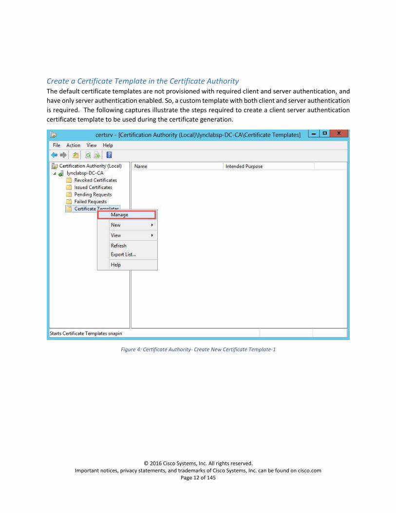
Create a Certificate Template in the Certificate Authority The default certificate templates are not provisioned with required client and server authentication, and
have only server authentication enabled. So, a custom template with both client and server authentication
is required. The following captures illustrate the steps required to create a client server authentication
certificate template to be used during the certificate generation.
Figure 4: Certificate Authority- Create New Certificate Template-1

© 2016 Cisco Systems, Inc. All rights reserved. Important notices, privacy statements, and trademarks of Cisco Systems, Inc. can be found on cisco.com
Page 13 of 145
Figure 5: Certificate Authority- Create New Certificate Template-2

© 2016 Cisco Systems, Inc. All rights reserved. Important notices, privacy statements, and trademarks of Cisco Systems, Inc. can be found on cisco.com
Page 14 of 145
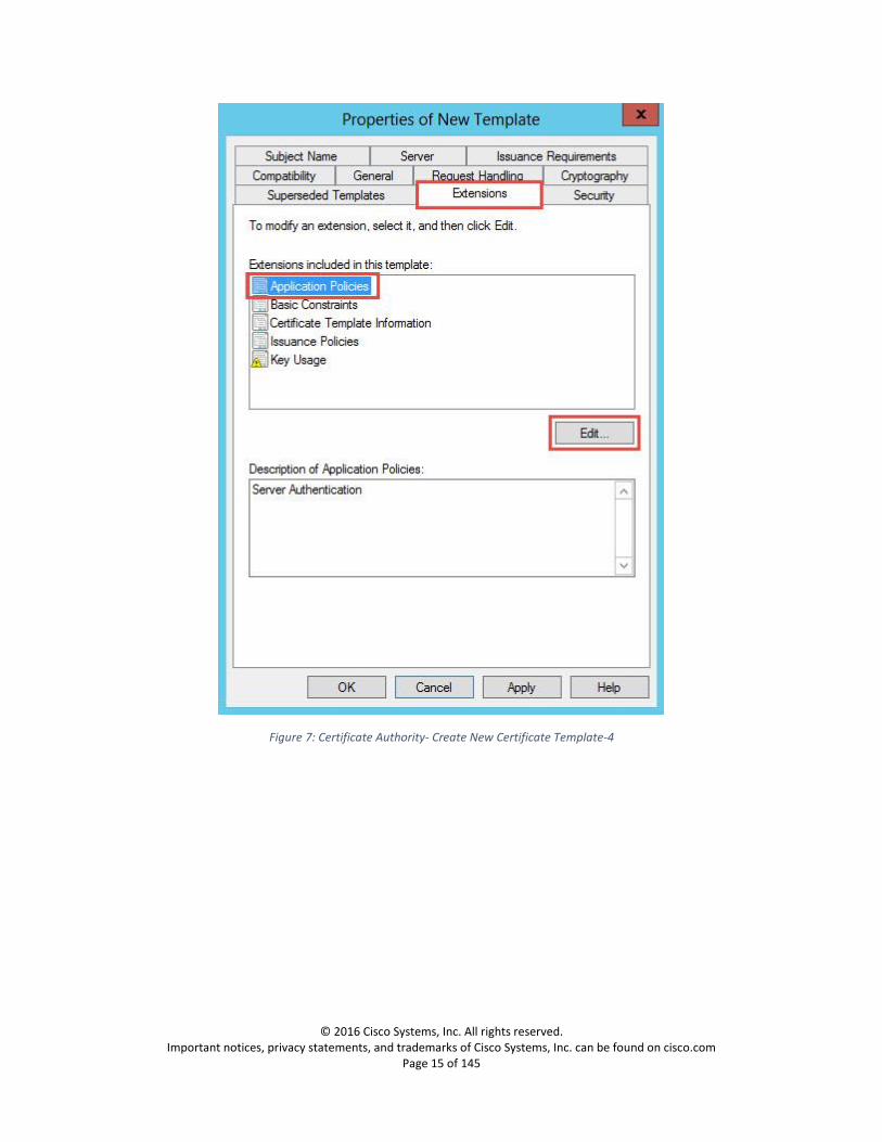
Figure 6: Certificate Authority- Create New Certificate Template-3
© 2016 Cisco Systems, Inc. All rights reserved. Important notices, privacy statements, and trademarks of Cisco Systems, Inc. can be found on cisco.com
Page 15 of 145
Figure 7: Certificate Authority- Create New Certificate Template-4

© 2016 Cisco Systems, Inc. All rights reserved. Important notices, privacy statements, and trademarks of Cisco Systems, Inc. can be found on cisco.com
Page 16 of 145
Figure 8: Certificate Authority- Create New Certificate Template-5

© 2016 Cisco Systems, Inc. All rights reserved. Important notices, privacy statements, and trademarks of Cisco Systems, Inc. can be found on cisco.com
Page 17 of 145
Figure 9: Certificate Authority- Create New Certificate Template-6

© 2016 Cisco Systems, Inc. All rights reserved. Important notices, privacy statements, and trademarks of Cisco Systems, Inc. can be found on cisco.com
Page 18 of 145
Figure 10: Certificate Authority- Create New Certificate Template-7
© 2016 Cisco Systems, Inc. All rights reserved. Important notices, privacy statements, and trademarks of Cisco Systems, Inc. can be found on cisco.com
Page 19 of 145
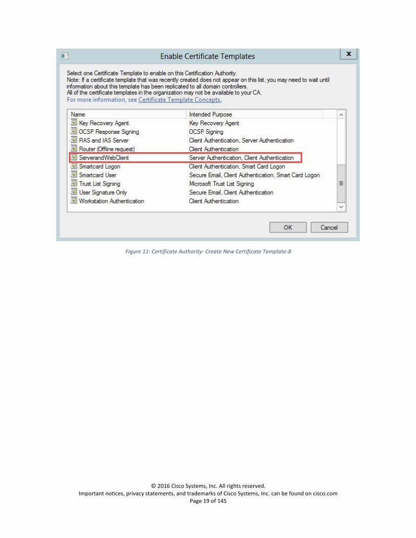
Figure 11: Certificate Authority- Create New Certificate Template-8

© 2016 Cisco Systems, Inc. All rights reserved. Important notices, privacy statements, and trademarks of Cisco Systems, Inc. can be found on cisco.com
Page 20 of 145
Figure 12: Certificate Authority- Create New Certificate Template-9

© 2016 Cisco Systems, Inc. All rights reserved. Important notices, privacy statements, and trademarks of Cisco Systems, Inc. can be found on cisco.com
Page 21 of 145
Submit a certificate request in the Certificate Authority Below is the process for creating a certificate request in the Certificate Authority
1. Navigate to https://<IP_Address_of_CA>/certsrv
Figure 13: Certificate Authority-Certificate Request-1
Figure 14: Certificate Authority-Certificate Request-2
Figure 15: Certificate Authority-Certificate Request-3

© 2016 Cisco Systems, Inc. All rights reserved. Important notices, privacy statements, and trademarks of Cisco Systems, Inc. can be found on cisco.com
Page 22 of 145
2. Copy the Generated CSR in to the text field shown below 3. Select the Certificate Template ‘ServerandWebClient’, this is the template we have created in
Create a Certificate Template in the Certificate Authority 4. Click submit and download the certificate
Figure 16: Certificate Authority-Certificate Request-4

© 2016 Cisco Systems, Inc. All rights reserved. Important notices, privacy statements, and trademarks of Cisco Systems, Inc. can be found on cisco.com
Page 23 of 145
Download a root certificate from CA
Figure 17: Certificate Authority-Download CA certificate-1

© 2016 Cisco Systems, Inc. All rights reserved. Important notices, privacy statements, and trademarks of Cisco Systems, Inc. can be found on cisco.com
Page 24 of 145
Figure 18: Certificate Authority-Download CA certificate-2

© 2016 Cisco Systems, Inc. All rights reserved. Important notices, privacy statements, and trademarks of Cisco Systems, Inc. can be found on cisco.com
Page 25 of 145
Cisco UCM Configuration
Loading certificates on Cisco UCM
Navigation: Cisco Unified OS Administration/Security->Certificate Management
Cisco UCM should trust Expressway-C
Cisco UCM Server Certificate
Cisco UCM by default has a self-signed certificate installed. This should be replaced with a certificate
generated from a trusted certificate authority.
Generate a CSR
Figure 19: Cisco UCM Generate CSR-1
1. Set Certificate Purpose: CallManager 2. Set Distribution: This will be the node to which you are generating a certificate 3. Set Common Name: This will be the node to which you are generating a certificate 4. Set Parent Domain: This will be the domain of the UCM node

© 2016 Cisco Systems, Inc. All rights reserved. Important notices, privacy statements, and trademarks of Cisco Systems, Inc. can be found on cisco.com
Page 26 of 145
Figure 20: Cisco UCM Generate CSR-2
Once the CSR is created, open the CSR, copy the content of the CSR and follow the steps shown in Submit
a certificate request in the Certificate Authority for creating a certificate request and downloading the
certificate
Upload root certificate to Cisco UCM
Follow the instructions in Download a root certificate from CA to download the root certificate authority
that issued the Expressway-C certificate
1. Click Upload Certificate/Certificate Chain 2. Select Certificate Purpose: Call Manager-trust

© 2016 Cisco Systems, Inc. All rights reserved. Important notices, privacy statements, and trademarks of Cisco Systems, Inc. can be found on cisco.com
Page 27 of 145
Figure 21: Cisco UCM Upload root certificate to Call Manager-trust
After upload is done, click on the certificate you uploaded and it should look similar to the one below.

© 2016 Cisco Systems, Inc. All rights reserved. Important notices, privacy statements, and trademarks of Cisco Systems, Inc. can be found on cisco.com
Page 28 of 145
Figure 22: Cisco UCM root certificate example
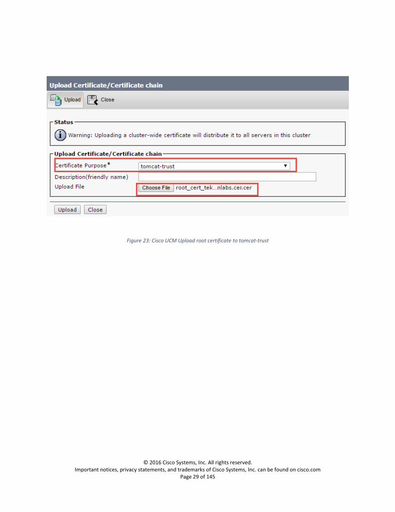
In similar, upload the root certificate to tomcat-trust
© 2016 Cisco Systems, Inc. All rights reserved. Important notices, privacy statements, and trademarks of Cisco Systems, Inc. can be found on cisco.com
Page 29 of 145
Figure 23: Cisco UCM Upload root certificate to tomcat-trust
© 2016 Cisco Systems, Inc. All rights reserved. Important notices, privacy statements, and trademarks of Cisco Systems, Inc. can be found on cisco.com
Page 30 of 145
Upload Server Certificate
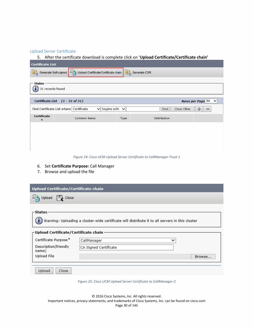
5. After the certificate download is complete click on ‘Upload Certificate/Certificate chain’
Figure 24: Cisco UCM Upload Server Certificate to CallManager-Trust-1
6. Set Certificate Purpose: Call Manager 7. Browse and upload the file
Figure 25: Cisco UCM Upload Server Certificate to CallManager-2
© 2016 Cisco Systems, Inc. All rights reserved. Important notices, privacy statements, and trademarks of Cisco Systems, Inc. can be found on cisco.com
Page 31 of 145
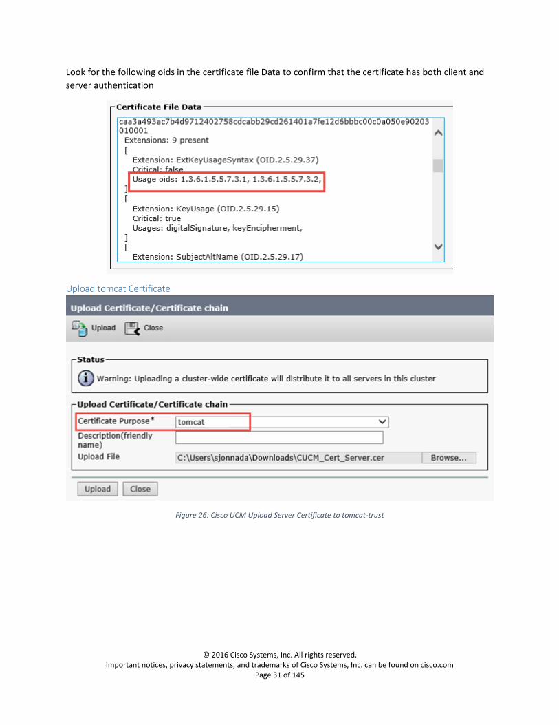
Look for the following oids in the certificate file Data to confirm that the certificate has both client and
server authentication
Upload tomcat Certificate
Figure 26: Cisco UCM Upload Server Certificate to tomcat-trust

© 2016 Cisco Systems, Inc. All rights reserved. Important notices, privacy statements, and trademarks of Cisco Systems, Inc. can be found on cisco.com
Page 32 of 145
Calling Search Space
Navigation: Call Routing->Class of Control->Calling Search Space

© 2016 Cisco Systems, Inc. All rights reserved. Important notices, privacy statements, and trademarks of Cisco Systems, Inc. can be found on cisco.com
Page 33 of 145
SIP Trunk Security Profile Configuration for Expressway-C
Navigation: System -> Security -> SIP Trunk Security Profile
1. Set Name: Enter a name for the security profile. When you save the new profile, the name displays in the SIP Trunk Security Profile drop-down list box in the Trunk Configuration window.
2. Set Description: Enter a description relevant to your security profile
3. Set Device Security Mode: Encrypted
4. Set Incoming Transport Type: TLS
5. Set Outgoing Transport Type: TLS
6. Set X.509 Subject Name: Enter the subject name of the X.509 certificate for the SIP trunk device,
which is the subject name of Expressway-C here.
7. Set Incoming Port: 5061
8. Confirm Accept unsolicited notification: is checked
If you want Cisco Unified Communications Manager to accept incoming non-INVITE, unsolicited notification messages that come via the SIP trunk, check this check box.
9. Confirm Accept replaces header: is checked
If you want Cisco Unified Communications Manager to accept new SIP dialogs, which have replaced existing SIP dialogs, check this check box

© 2016 Cisco Systems, Inc. All rights reserved. Important notices, privacy statements, and trademarks of Cisco Systems, Inc. can be found on cisco.com
Page 34 of 145
Figure 27: Cisco UCM Security Profile for Expressway-C Trunk

© 2016 Cisco Systems, Inc. All rights reserved. Important notices, privacy statements, and trademarks of Cisco Systems, Inc. can be found on cisco.com
Page 35 of 145
Trunk to Expressway-C Gateway
To configure Expressway-C, please refer to section Expressway-C Configuration
Navigation: Device -> Trunk
Device Information 1. Set Trunk Type: SIP Trunk 2. Set Device Protocol: SIP
3. Set Trunk Service Type: None
4. Set Device Name: Enter a name for the trunk
5. Set Description: Enter a description relevant to your trunk
6. Set Device Pool: Select the Device Pool you configured under System -> Device Pool
For trunks, device pools specify a list of Cisco Unified Communications Managers that the trunk uses to distribute the call load dynamically
7. Set Media Resource Group List: Select the Media Resource Group List you configured under Media Resources -> Media Resource Group List
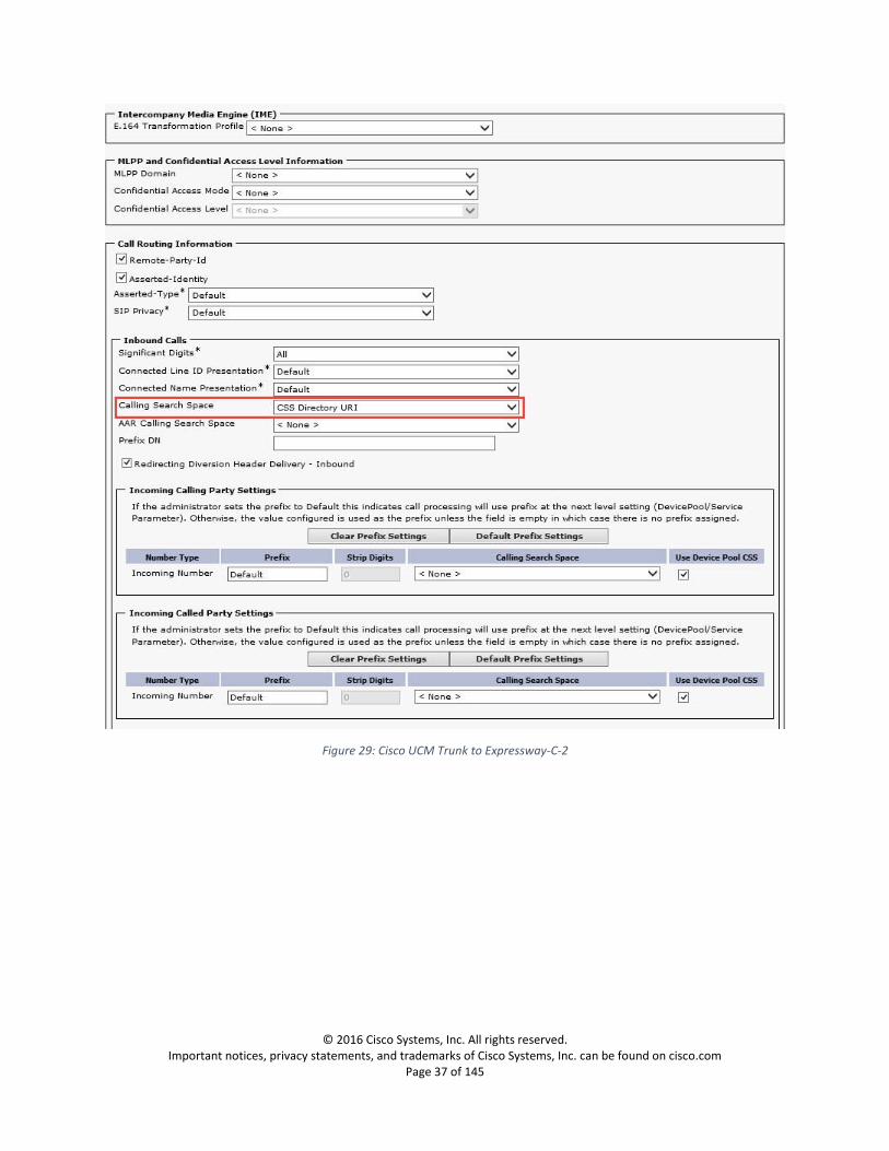
8. Confirm SRTP Allowed: is checked 9. Set Consider Traffic on This Trunk Secure: When using both SRTP and TLS 10. Set Calling Search Space: CSS Directory URI
SIP Information 11. Set the Destination Address: Enter the FQDN of the Expressway-C to which you are establishing
a trunk.
12. Set SIP trunk Security Profile: Select the security profile you created under System -> Security ->
SIP Security Profile
13. Set SIP Profile: Select the SIP Profile you created under Device -> Device Settings -> SIP Profile
14. Set Normalization Script: Select the existing normalization script vcs-interop

© 2016 Cisco Systems, Inc. All rights reserved. Important notices, privacy statements, and trademarks of Cisco Systems, Inc. can be found on cisco.com
Page 36 of 145
Figure 28: Cisco UCM Trunk to Expressway-C-1
© 2016 Cisco Systems, Inc. All rights reserved. Important notices, privacy statements, and trademarks of Cisco Systems, Inc. can be found on cisco.com
Page 37 of 145
Figure 29: Cisco UCM Trunk to Expressway-C-2

© 2016 Cisco Systems, Inc. All rights reserved. Important notices, privacy statements, and trademarks of Cisco Systems, Inc. can be found on cisco.com
Page 38 of 145
Figure 30: Cisco UCM Trunk to Expressway-C-3
© 2016 Cisco Systems, Inc. All rights reserved. Important notices, privacy statements, and trademarks of Cisco Systems, Inc. can be found on cisco.com
Page 39 of 145
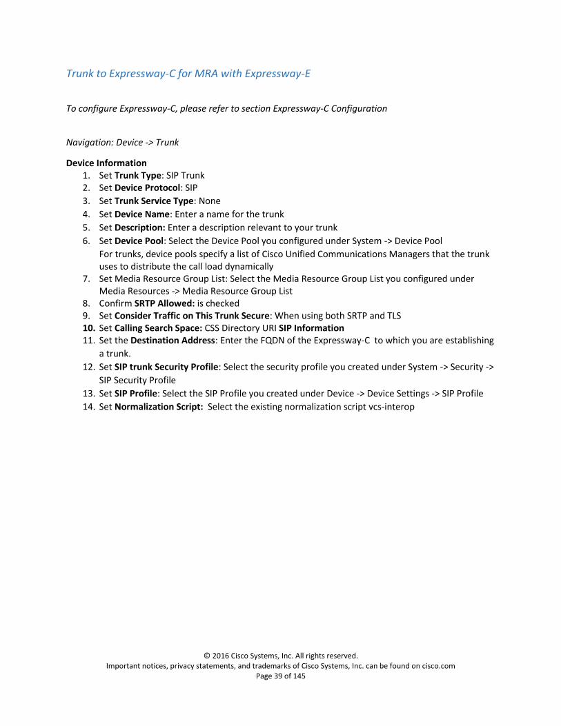
Trunk to Expressway-C for MRA with Expressway-E
To configure Expressway-C, please refer to section Expressway-C Configuration
Navigation: Device -> Trunk
Device Information 1. Set Trunk Type: SIP Trunk 2. Set Device Protocol: SIP
3. Set Trunk Service Type: None
4. Set Device Name: Enter a name for the trunk
5. Set Description: Enter a description relevant to your trunk
6. Set Device Pool: Select the Device Pool you configured under System -> Device Pool
For trunks, device pools specify a list of Cisco Unified Communications Managers that the trunk uses to distribute the call load dynamically
7. Set Media Resource Group List: Select the Media Resource Group List you configured under Media Resources -> Media Resource Group List
8. Confirm SRTP Allowed: is checked 9. Set Consider Traffic on This Trunk Secure: When using both SRTP and TLS 10. Set Calling Search Space: CSS Directory URI SIP Information 11. Set the Destination Address: Enter the FQDN of the Expressway-C to which you are establishing
a trunk.
12. Set SIP trunk Security Profile: Select the security profile you created under System -> Security ->
SIP Security Profile
13. Set SIP Profile: Select the SIP Profile you created under Device -> Device Settings -> SIP Profile
14. Set Normalization Script: Select the existing normalization script vcs-interop

© 2016 Cisco Systems, Inc. All rights reserved. Important notices, privacy statements, and trademarks of Cisco Systems, Inc. can be found on cisco.com
Page 40 of 145
Figure 31: UCM Trunk to Expressway-C for MRA1

© 2016 Cisco Systems, Inc. All rights reserved. Important notices, privacy statements, and trademarks of Cisco Systems, Inc. can be found on cisco.com
Page 41 of 145
Figure 32: UCM Trunk to Expressway-C for MRA2
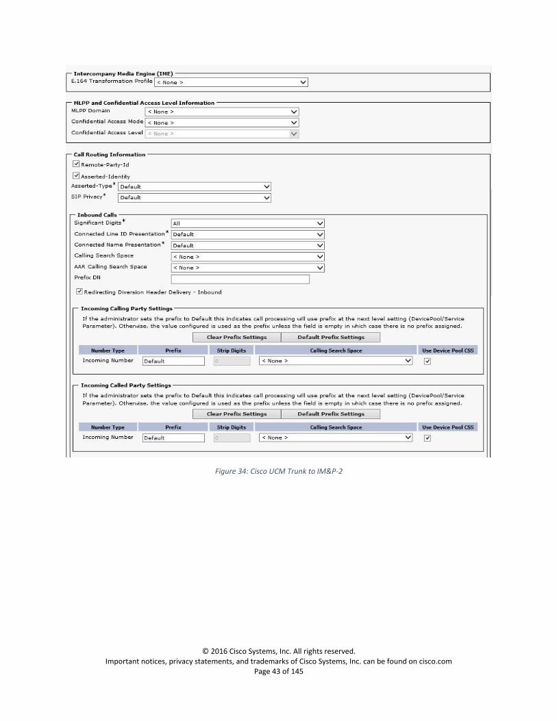
Trunk to IM and Presence Server Navigation: Device -> Trunk
Device Information 1. Set Trunk Type: SIP Trunk 2. Set Device Protocol: SIP
3. Set Trunk Service Type: None
4. Set Device Name: Enter a name for the trunk
5. Set Description: Enter a description relevant to your trunk
6. Set Device Pool: Default
For trunks, device pools specify a list of Cisco Unified Communications Managers that the trunk uses to distribute the call load dynamically
SIP Information 7. Set the Destination Address: Enter the FQDN of the Cisco IM&P Server to which you are
establishing a trunk.
8. Set SIP trunk Security Profile: Non-Secure SIP Trunk Profile
9. Set SIP Profile: Select the SIP Profile you created under Device -> Device Settings -> SIP Profile

© 2016 Cisco Systems, Inc. All rights reserved. Important notices, privacy statements, and trademarks of Cisco Systems, Inc. can be found on cisco.com
Page 42 of 145
Figure 33: Cisco UCM Trunk to IM&P-1
© 2016 Cisco Systems, Inc. All rights reserved. Important notices, privacy statements, and trademarks of Cisco Systems, Inc. can be found on cisco.com
Page 43 of 145
Figure 34: Cisco UCM Trunk to IM&P-2

© 2016 Cisco Systems, Inc. All rights reserved. Important notices, privacy statements, and trademarks of Cisco Systems, Inc. can be found on cisco.com
Page 44 of 145
Figure 35: Cisco UCM Trunk to IM&P-3

© 2016 Cisco Systems, Inc. All rights reserved. Important notices, privacy statements, and trademarks of Cisco Systems, Inc. can be found on cisco.com
Page 45 of 145
SIP Route Pattern
Navigation: Call Routing -> SIP Route Pattern
1. Set IPv4 Pattern: Enter the Domain name of the deployment
2. Set Description: Enter the description of the SIP Route Pattern
3. Set SIP Trunk: From the drop-down list select your trunk to Expressway-C
Figure 36: Cisco UCM SIP Route Pattern

© 2016 Cisco Systems, Inc. All rights reserved. Important notices, privacy statements, and trademarks of Cisco Systems, Inc. can be found on cisco.com
Page 46 of 145
Media Resource Group Configuration
Navigation: Media Resources->Media Resource Group
Figure 37: Media Resource Group Configuration

© 2016 Cisco Systems, Inc. All rights reserved. Important notices, privacy statements, and trademarks of Cisco Systems, Inc. can be found on cisco.com
Page 47 of 145
Media Resource Group List Configuration
Navigation: Media Resources->Media Resource Group List
Add the above created media resource group to a newly defined media resource group list.
Figure 38: Media Resource Group List Configuration

© 2016 Cisco Systems, Inc. All rights reserved. Important notices, privacy statements, and trademarks of Cisco Systems, Inc. can be found on cisco.com
Page 48 of 145
Add MRGL to Device or Device Pool
Navigation: System->Device Pool
Figure 39: Device Pool Configuration -1

© 2016 Cisco Systems, Inc. All rights reserved. Important notices, privacy statements, and trademarks of Cisco Systems, Inc. can be found on cisco.com
Page 49 of 145
Figure 40: Device Pool Configuration -2

© 2016 Cisco Systems, Inc. All rights reserved. Important notices, privacy statements, and trademarks of Cisco Systems, Inc. can be found on cisco.com
Page 50 of 145
Cisco UCM LDAP Configuration
LDAP System Configuration
Navigation: System->LDAP->LDAP System
Figure 41: LDAP System Configuration
LDAP Directory
Navigation: System->LDAP->LDAP Directory
1. Set LDAP Configuration Name: Enter a unique name for the LDAP directory 2. Set LDAP Manager Distinguished Name: Enter the user ID of the LDAP Manager, who has
administrator access rights 3. Set LDAP Password: Enter a password for the LDAP Manager 4. Set Confirm Password: Renter the password you provided in LDAP Password field 5. Set LDAP User Search Base: Enter the location where all LDAP users exist. This location acts as a
container or a directory. This information varies depending on customer setup. 6. LDAP Server Information:
a. Set Host Name or IP Address for Server: Enter the host name or IP address of the server where the data for this LDAP directory resides.
b. Set LDAP Port: Enter the port number on which the corporate directory receives the LDAP requests.
c. Confirm Use SSL: is checked 7. Click save 8. To sync users from the LDAP Directory directly into Communications Manager, you must activate
the Cisco DirSync service 9. Before performing full sync, make sure ‘Email’ field for users are configured in Active Directory
Users and Computers as shown in Figure 2: Active Directory User

© 2016 Cisco Systems, Inc. All rights reserved. Important notices, privacy statements, and trademarks of Cisco Systems, Inc. can be found on cisco.com
Page 51 of 145
Figure 42: Cisco UCM LDAP Directory

© 2016 Cisco Systems, Inc. All rights reserved. Important notices, privacy statements, and trademarks of Cisco Systems, Inc. can be found on cisco.com
Page 52 of 145
LDAP Authentication
Figure 43: Cisco UCM LDAP Authentication
LDAP-Synced users Navigation: User Management-> End User
Figure 44: LDAP-Synced users

© 2016 Cisco Systems, Inc. All rights reserved. Important notices, privacy statements, and trademarks of Cisco Systems, Inc. can be found on cisco.com
Page 53 of 145
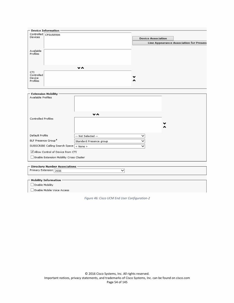
User Management Configuration – Settings to Associate Services
Cisco UCM End User Configuration
Navigation: User Management->End User
Figure 45: Cisco UCM End User Configuration-1
© 2016 Cisco Systems, Inc. All rights reserved. Important notices, privacy statements, and trademarks of Cisco Systems, Inc. can be found on cisco.com
Page 54 of 145
Figure 46: Cisco UCM End User Configuration-2

© 2016 Cisco Systems, Inc. All rights reserved. Important notices, privacy statements, and trademarks of Cisco Systems, Inc. can be found on cisco.com
Page 55 of 145
Figure 47: Cisco UCM End User Configuration-3

© 2016 Cisco Systems, Inc. All rights reserved. Important notices, privacy statements, and trademarks of Cisco Systems, Inc. can be found on cisco.com
Page 56 of 145
Cisco Jabber User Configuration
Navigation: Device->Phone
Figure 48: Cisco UCM Jabber Client Configuration-1

© 2016 Cisco Systems, Inc. All rights reserved. Important notices, privacy statements, and trademarks of Cisco Systems, Inc. can be found on cisco.com
Page 57 of 145
Figure 49: Cisco UCM Jabber Client Configuration-2

© 2016 Cisco Systems, Inc. All rights reserved. Important notices, privacy statements, and trademarks of Cisco Systems, Inc. can be found on cisco.com
Page 58 of 145
Figure 50: Cisco UCM Jabber Client Configuration-3

© 2016 Cisco Systems, Inc. All rights reserved. Important notices, privacy statements, and trademarks of Cisco Systems, Inc. can be found on cisco.com
Page 59 of 145
Figure 51: Cisco UCM Jabber Client Configuration-4

© 2016 Cisco Systems, Inc. All rights reserved. Important notices, privacy statements, and trademarks of Cisco Systems, Inc. can be found on cisco.com
Page 60 of 145
Figure 52: Cisco UCM Jabber Client Configuration-5

© 2016 Cisco Systems, Inc. All rights reserved. Important notices, privacy statements, and trademarks of Cisco Systems, Inc. can be found on cisco.com
Page 61 of 145
Figure 53: Cisco UCM Jabber Client Configuration-6

© 2016 Cisco Systems, Inc. All rights reserved. Important notices, privacy statements, and trademarks of Cisco Systems, Inc. can be found on cisco.com
Page 62 of 145
Figure 54: Cisco UCM Jabber Client Configuration-7

© 2016 Cisco Systems, Inc. All rights reserved. Important notices, privacy statements, and trademarks of Cisco Systems, Inc. can be found on cisco.com
Page 63 of 145
End Point configurations
Cisco Telepresence DX70 Configuration
Device Configuration
Navigation: Device->Phone->DX70
Figure 55: DX70 Device Configuration-1

© 2016 Cisco Systems, Inc. All rights reserved. Important notices, privacy statements, and trademarks of Cisco Systems, Inc. can be found on cisco.com
Page 64 of 145
Figure 56: DX70 Device Configuration-2

© 2016 Cisco Systems, Inc. All rights reserved. Important notices, privacy statements, and trademarks of Cisco Systems, Inc. can be found on cisco.com
Page 65 of 145
Figure 57: DX70 Device Configuration-3

© 2016 Cisco Systems, Inc. All rights reserved. Important notices, privacy statements, and trademarks of Cisco Systems, Inc. can be found on cisco.com
Page 66 of 145
Figure 58: DX70 Device Configuration-4

© 2016 Cisco Systems, Inc. All rights reserved. Important notices, privacy statements, and trademarks of Cisco Systems, Inc. can be found on cisco.com
Page 67 of 145
Figure 59: DX70 Device Configuration-5
Figure 60: DX70 Device Configuration-6

© 2016 Cisco Systems, Inc. All rights reserved. Important notices, privacy statements, and trademarks of Cisco Systems, Inc. can be found on cisco.com
Page 68 of 145
Line Configuration
Navigation: Device->Phone->DX70->Line [1]
Figure 61: DX70 Line [1] Configuration-1

© 2016 Cisco Systems, Inc. All rights reserved. Important notices, privacy statements, and trademarks of Cisco Systems, Inc. can be found on cisco.com
Page 69 of 145
Figure 62: DX70 Line [1] Configuration-2
© 2016 Cisco Systems, Inc. All rights reserved. Important notices, privacy statements, and trademarks of Cisco Systems, Inc. can be found on cisco.com
Page 70 of 145
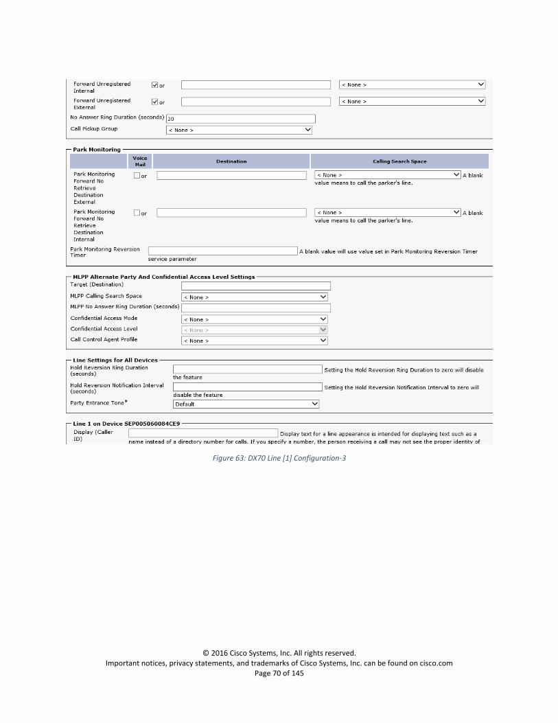
Figure 63: DX70 Line [1] Configuration-3
© 2016 Cisco Systems, Inc. All rights reserved. Important notices, privacy statements, and trademarks of Cisco Systems, Inc. can be found on cisco.com
Page 71 of 145
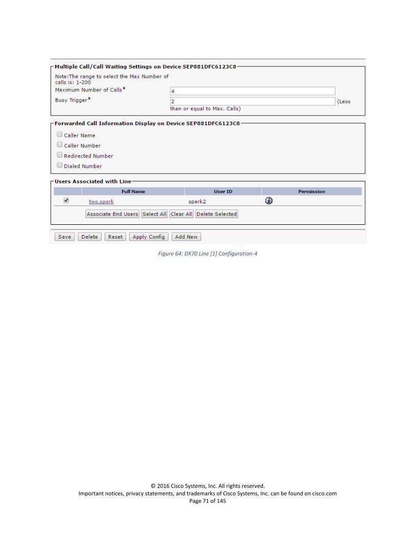
Figure 64: DX70 Line [1] Configuration-4

© 2016 Cisco Systems, Inc. All rights reserved. Important notices, privacy statements, and trademarks of Cisco Systems, Inc. can be found on cisco.com
Page 72 of 145
Cisco DX80 Configuration
Device Configuration
Navigation: Device->Phone->DX80
Figure 65: DX80 Device Configuration-1

© 2016 Cisco Systems, Inc. All rights reserved. Important notices, privacy statements, and trademarks of Cisco Systems, Inc. can be found on cisco.com
Page 73 of 145
Figure 66: DX80 Device Configuration-2

© 2016 Cisco Systems, Inc. All rights reserved. Important notices, privacy statements, and trademarks of Cisco Systems, Inc. can be found on cisco.com
Page 74 of 145
Figure 67: DX80 Device Configuration-3
© 2016 Cisco Systems, Inc. All rights reserved. Important notices, privacy statements, and trademarks of Cisco Systems, Inc. can be found on cisco.com
Page 75 of 145
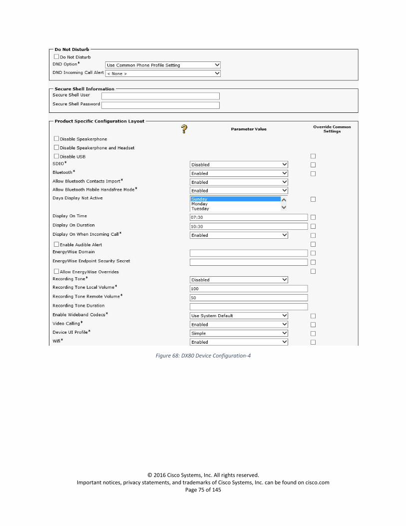
Figure 68: DX80 Device Configuration-4

© 2016 Cisco Systems, Inc. All rights reserved. Important notices, privacy statements, and trademarks of Cisco Systems, Inc. can be found on cisco.com
Page 76 of 145
Figure 69: DX80 Device Configuration-5

© 2016 Cisco Systems, Inc. All rights reserved. Important notices, privacy statements, and trademarks of Cisco Systems, Inc. can be found on cisco.com
Page 77 of 145
Figure 70: DX80 Device Configuration-6

© 2016 Cisco Systems, Inc. All rights reserved. Important notices, privacy statements, and trademarks of Cisco Systems, Inc. can be found on cisco.com
Page 78 of 145
Line Configuration
Navigation: Device->Phone-> DX80 ->Line [1]
Figure 71: DX80 Line [1] Configuration-1

© 2016 Cisco Systems, Inc. All rights reserved. Important notices, privacy statements, and trademarks of Cisco Systems, Inc. can be found on cisco.com
Page 79 of 145
Figure 72: DX80 Line [1] Configuration-2

© 2016 Cisco Systems, Inc. All rights reserved. Important notices, privacy statements, and trademarks of Cisco Systems, Inc. can be found on cisco.com
Page 80 of 145
Figure 73: DX80 Line [1] Configuration-3
Figure 74: DX80 Line [1] Configuration-4

© 2016 Cisco Systems, Inc. All rights reserved. Important notices, privacy statements, and trademarks of Cisco Systems, Inc. can be found on cisco.com
Page 81 of 145
Expressway-C Configuration
System Configuration
IP Configuration
Navigation: System->IP Address
Figure 75: Expressway-C-IP Address Configuration

© 2016 Cisco Systems, Inc. All rights reserved. Important notices, privacy statements, and trademarks of Cisco Systems, Inc. can be found on cisco.com
Page 82 of 145
Option Keys
Navigation: Maintenance->Option keys
Note: AV integration between Skype for Business and UCM via Expressway requires the option keys as
shown below.
Ensure the required licenses for the highlighted options are installed and available if video integration is
performed.
Figure 76: Expressway-C-Options
© 2016 Cisco Systems, Inc. All rights reserved. Important notices, privacy statements, and trademarks of Cisco Systems, Inc. can be found on cisco.com
Page 83 of 145
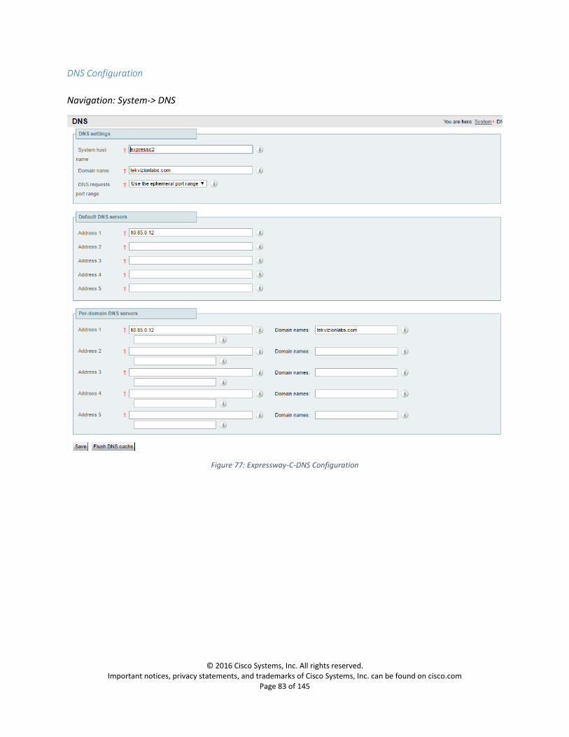
DNS Configuration
Navigation: System-> DNS
Figure 77: Expressway-C-DNS Configuration

© 2016 Cisco Systems, Inc. All rights reserved. Important notices, privacy statements, and trademarks of Cisco Systems, Inc. can be found on cisco.com
Page 84 of 145
NTP Configuration
Navigation: System->Time
Figure 78: Expressway-C-NTP Configuration

© 2016 Cisco Systems, Inc. All rights reserved. Important notices, privacy statements, and trademarks of Cisco Systems, Inc. can be found on cisco.com
Page 85 of 145
TLS in SIP Configuration
Navigation: Configuration->Protocols->SIP
Figure 79: Expressway-C-SIP Configuration

© 2016 Cisco Systems, Inc. All rights reserved. Important notices, privacy statements, and trademarks of Cisco Systems, Inc. can be found on cisco.com
Page 86 of 145
Microsoft Lync B2BUA configuration (Skype for Business B2BUA)
Navigation: Applications->B2BUA->Microsoft Interoperability->Configuration
1. Set Microsoft Interoperability: Enabled 2. Set destination address: Enter the IP address or FQDN of the server to which the B2BUA sends
the signaling messages, Skype for Business Server here. 3. Set destination port: 5061 4. Set signaling transport: TLS
Figure 80: Expressway-C-Microsoft Lync (Skype for Business B2BUA) B2BUA Configuration

© 2016 Cisco Systems, Inc. All rights reserved. Important notices, privacy statements, and trademarks of Cisco Systems, Inc. can be found on cisco.com
Page 87 of 145
Microsoft Lync (Skype for Business) B2BUA trusted hosts Expressway and Skype for Business Front End server should be added to the trusted host list.
Navigation: Applications->B2BUA->Microsoft Lync->B2BUA trusted hosts
Figure 81: Expressway-C-Microsoft Lync (Skype for Business) B2BUA trusted hosts-1
Figure 82: Expressway-C-Microsoft Lync (Skype for Business) B2BUA trusted hosts-2
Loading server and trust certificates
Expressway-C Server Certificate
Navigation: Maintenance->Security Certificates->Server certificate
This is used to manage the Expressway-C's server certificate. This certificate is used to identify the
Expressway-C server when it communicates with systems using TLS encryption.

© 2016 Cisco Systems, Inc. All rights reserved. Important notices, privacy statements, and trademarks of Cisco Systems, Inc. can be found on cisco.com
Page 88 of 145
Figure 83: Expressway-C-Generate CSR-1
List of SAN entries required for Generating CSR:
Fqdn of the expressway, expressc2.tekvizionlabs.com here.
Fqdn of the CUCM, clus30pub.tekvizionlabs.com here.

© 2016 Cisco Systems, Inc. All rights reserved. Important notices, privacy statements, and trademarks of Cisco Systems, Inc. can be found on cisco.com
Page 89 of 145
Figure 84: Expressway-C-Generate CSR-2
After the CSR is generated and downloaded, follow the steps described in Submit a certificate request in
the Certificate Authority to create a certificate request in CA.

© 2016 Cisco Systems, Inc. All rights reserved. Important notices, privacy statements, and trademarks of Cisco Systems, Inc. can be found on cisco.com
Page 90 of 145
Figure 85: Expressway-C-Server Certificate Upload

© 2016 Cisco Systems, Inc. All rights reserved. Important notices, privacy statements, and trademarks of Cisco Systems, Inc. can be found on cisco.com
Page 91 of 145
Expressway-C Trusted CA Certificate
Navigation: Maintenance->Security Certificates->Trusted CA certificate
This allows you to manage the list of certificates for the Certificate Authorities (CAs) trusted by this
Expressway-C. When a TLS connection to Expressway-C mandates certificate verification, the certificate
presented to the Expressway-C must be signed by a trusted CA in this list and there must be a full chain
of trust (intermediate CAs) to the root CA.
Follow the steps described in Download a root certificate from CA to download the root certificate from
CA.
Figure 86 Expressway-C-Trusted Certificate Upload
Call Routing
Navigation: Configuration->Call routing
1. Set Call Signaling optimization: On 2. Set Call loop detection mode: On
Figure 87: Expressway-C-Call routing

© 2016 Cisco Systems, Inc. All rights reserved. Important notices, privacy statements, and trademarks of Cisco Systems, Inc. can be found on cisco.com
Page 92 of 145
Call Flows
CISCO UCM -> Skype for Business Internal
The Audio/Video signaling flow from Cisco UCM (including PSTN calls) to Skype for Business are as
follows:
1. The CISCO UCM routes it to the Expressway-C. 2. Expressway-C routes the Cisco UCM call to the Skype for Business Front End. 3. The resulting signaling path:
a. Audio/Video signaling: session is established between the CISCO UCM and the B2BUA on the Expressway-C and Expressway-C to Skype for Business Front End.
Skype for Business->CISCO UCM Internal
The Audio/Video (AV) signaling flows are as follows:
1. A Skype for Business user starts a call. 2. The Skype for Business Front End routes it to the Expressway-C. 3. Expressway-C routes the SIP AV invite to CUCM and thereby it is sent to the CUCM endpoint. 4. The resulting signaling path:
a. Audio/Video signaling: session is established between the Skype for Business Front End and the B2BUA on the Expressway-C.
CISCO UCM -> Skype for Business External
The Audio/Video signaling flow from Cisco UCM (including PSTN calls) to Skype for Business are as
follows:
1. The Expressway-E routes the call to Expressway-C and the expressway-C routes the call towards CISCO UCM and the CUCM routes it to the Expressway-C.
2. Expressway-C routes the Cisco UCM call to the Skype for Business Front End. 3. The resulting signaling path:
a. Audio/Video Media: Expressway- E and Microsoft Edge server anchors the media between Cisco and Skype for Business external clients

© 2016 Cisco Systems, Inc. All rights reserved. Important notices, privacy statements, and trademarks of Cisco Systems, Inc. can be found on cisco.com
Page 93 of 145
Zone and Search Rule Configuration for Audio/Video Integration
Figure 88: Audio/Video Call flow Skype for Business to UCM
© 2016 Cisco Systems, Inc. All rights reserved. Important notices, privacy statements, and trademarks of Cisco Systems, Inc. can be found on cisco.com
Page 94 of 145
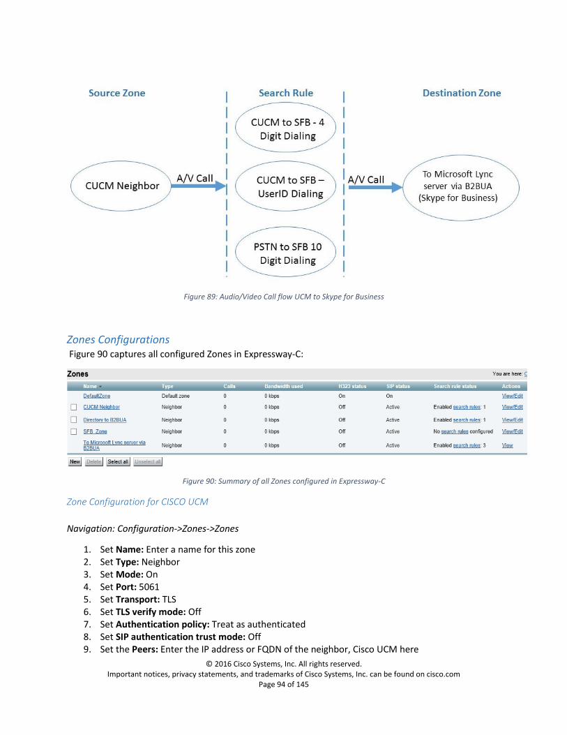
Figure 89: Audio/Video Call flow UCM to Skype for Business
Zones Configurations Figure 90 captures all configured Zones in Expressway-C:
Figure 90: Summary of all Zones configured in Expressway-C
Zone Configuration for CISCO UCM
Navigation: Configuration->Zones->Zones
1. Set Name: Enter a name for this zone 2. Set Type: Neighbor 3. Set Mode: On 4. Set Port: 5061 5. Set Transport: TLS 6. Set TLS verify mode: Off 7. Set Authentication policy: Treat as authenticated 8. Set SIP authentication trust mode: Off 9. Set the Peers: Enter the IP address or FQDN of the neighbor, Cisco UCM here

© 2016 Cisco Systems, Inc. All rights reserved. Important notices, privacy statements, and trademarks of Cisco Systems, Inc. can be found on cisco.com
Page 95 of 145
Figure 91: Expressway-C Zone Configuration for UCM-1

© 2016 Cisco Systems, Inc. All rights reserved. Important notices, privacy statements, and trademarks of Cisco Systems, Inc. can be found on cisco.com
Page 96 of 145
Figure 92: Expressway-C Zone Configuration for UCM-2
© 2016 Cisco Systems, Inc. All rights reserved. Important notices, privacy statements, and trademarks of Cisco Systems, Inc. can be found on cisco.com
Page 97 of 145
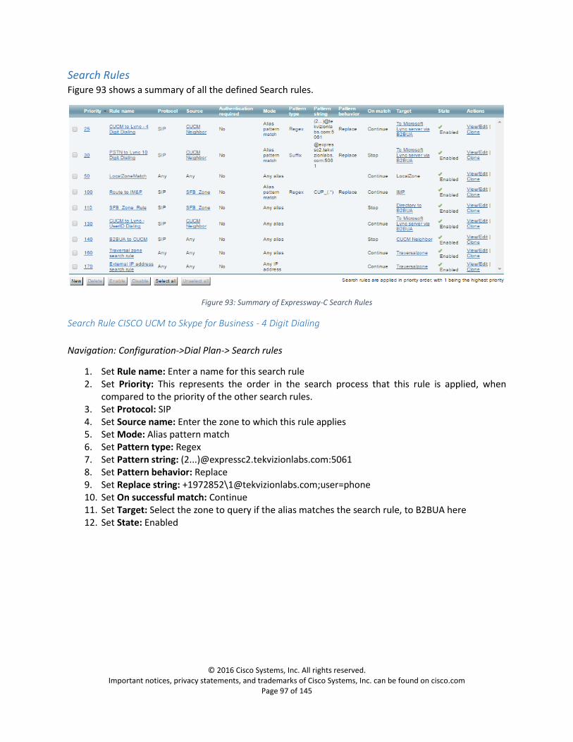
Search Rules Figure 93 shows a summary of all the defined Search rules.
Figure 93: Summary of Expressway-C Search Rules
Search Rule CISCO UCM to Skype for Business - 4 Digit Dialing
Navigation: Configuration->Dial Plan-> Search rules
1. Set Rule name: Enter a name for this search rule 2. Set Priority: This represents the order in the search process that this rule is applied, when
compared to the priority of the other search rules. 3. Set Protocol: SIP 4. Set Source name: Enter the zone to which this rule applies 5. Set Mode: Alias pattern match 6. Set Pattern type: Regex 7. Set Pattern string: (2...)@expressc2.tekvizionlabs.com:5061 8. Set Pattern behavior: Replace 9. Set Replace string: +1972852\[email protected];user=phone 10. Set On successful match: Continue 11. Set Target: Select the zone to query if the alias matches the search rule, to B2BUA here 12. Set State: Enabled

© 2016 Cisco Systems, Inc. All rights reserved. Important notices, privacy statements, and trademarks of Cisco Systems, Inc. can be found on cisco.com
Page 98 of 145
Figure 94: Expressway-C Search rule CISCO UCM to Skype for Business - 4 Digit Dialing
Search Rule CISCO UCM to Skype for Business - UserID Dialing
Navigation: Configuration->Dial Plan-> Search rules
1. Set Rule name: Enter a name for this search rule 2. Set Priority: This represents the order in the search process that this rule is applied, when
compared to the priority of the other search rules. 3. Set Protocol: SIP 4. Set Source: Named 5. Set Source name: CUCM_ Neighbor 6. Set Target: To Microsoft Lync server via B2BUA (Skype for Business server) 7. Set State: Enabled

© 2016 Cisco Systems, Inc. All rights reserved. Important notices, privacy statements, and trademarks of Cisco Systems, Inc. can be found on cisco.com
Page 99 of 145
Figure 95: Expressway-C Search rule for URI based dialing from CISCO UCM to Skype for Business
Search Rule B2BUA to CISCO UCM
Navigation: Configuration->Dial Plan-> Search rules
1. Set Rule name: Enter a name for this search rule 2. Set Priority: This represents the order in the search process that this rule is applied, when
compared to the priority of the other search rules. 3. Set Protocol: SIP 4. Set Source: Any 5. Set Mode: Any alias 6. Set On successful match: Stop 7. Set Target: CUCM_ Neighbor 8. Set State: Enabled

© 2016 Cisco Systems, Inc. All rights reserved. Important notices, privacy statements, and trademarks of Cisco Systems, Inc. can be found on cisco.com
Page 100 of 145
Figure 96: Expressway-C Search rule for B2BUA to CUCM
Configuring Secure Traversal Zone Connection for Unified Communications
To support Unified Communications features (such as mobile and remote access or Jabber Guest), there
must be a Unified Communications traversal zone connection between the Expressway-C and the
Expressway-E. This involves:
Installing suitable security certificates on the Expressway-C and the Expressway-E.
Configuring a Unified Communications traversal zone between the Expressway-C and the Expressway-E
Installing Expressway Security Certificates
Expressway-C and Expressway-E should have the trusted and signed CA certificate. Refer to Loading
server and trusted certificates in the expressway-C section for certificate request and upload.
Note: When you generate a CSR in the expressway-c, you must include the phone security profile
names under the Unified CM Phone Security profile names in the Alternative names section as shown
below, this will help you to register jabber as an external User:

© 2016 Cisco Systems, Inc. All rights reserved. Important notices, privacy statements, and trademarks of Cisco Systems, Inc. can be found on cisco.com
Page 101 of 145
Figure 97:Expressway-C certificate request
Expressway-C Traversal Zone Configuration There should be a Unified Communications traversal zone between Expressway-C and Expressway-E for
the MRA services.
Navigation: Configuration->Zones->Zones
1. Set Name: Enter a name for this zone 2. Set Type: Unified Communications traversal 3. Username: username for this traversal zone to communicate with EXP-E 4. Password: Password 5. Set SIP Mode: On 6. Set Port: 7003 7. Authentication policy: Do not check credentials 8. Set Peer 1 address: Enter the FQDN of the Expressway-E
© 2016 Cisco Systems, Inc. All rights reserved. Important notices, privacy statements, and trademarks of Cisco Systems, Inc. can be found on cisco.com
Page 102 of 145
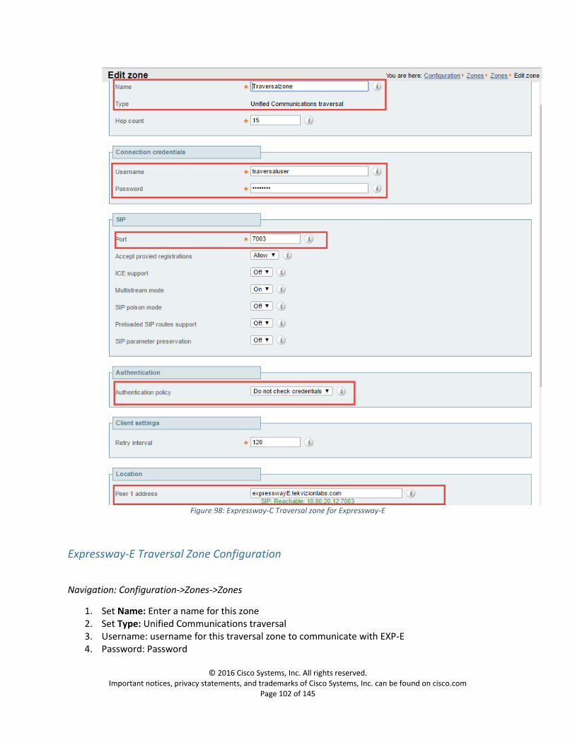
Figure 98: Expressway-C Traversal zone for Expressway-E
Expressway-E Traversal Zone Configuration
Navigation: Configuration->Zones->Zones
1. Set Name: Enter a name for this zone 2. Set Type: Unified Communications traversal 3. Username: username for this traversal zone to communicate with EXP-E 4. Password: Password
© 2016 Cisco Systems, Inc. All rights reserved. Important notices, privacy statements, and trademarks of Cisco Systems, Inc. can be found on cisco.com
Page 103 of 145
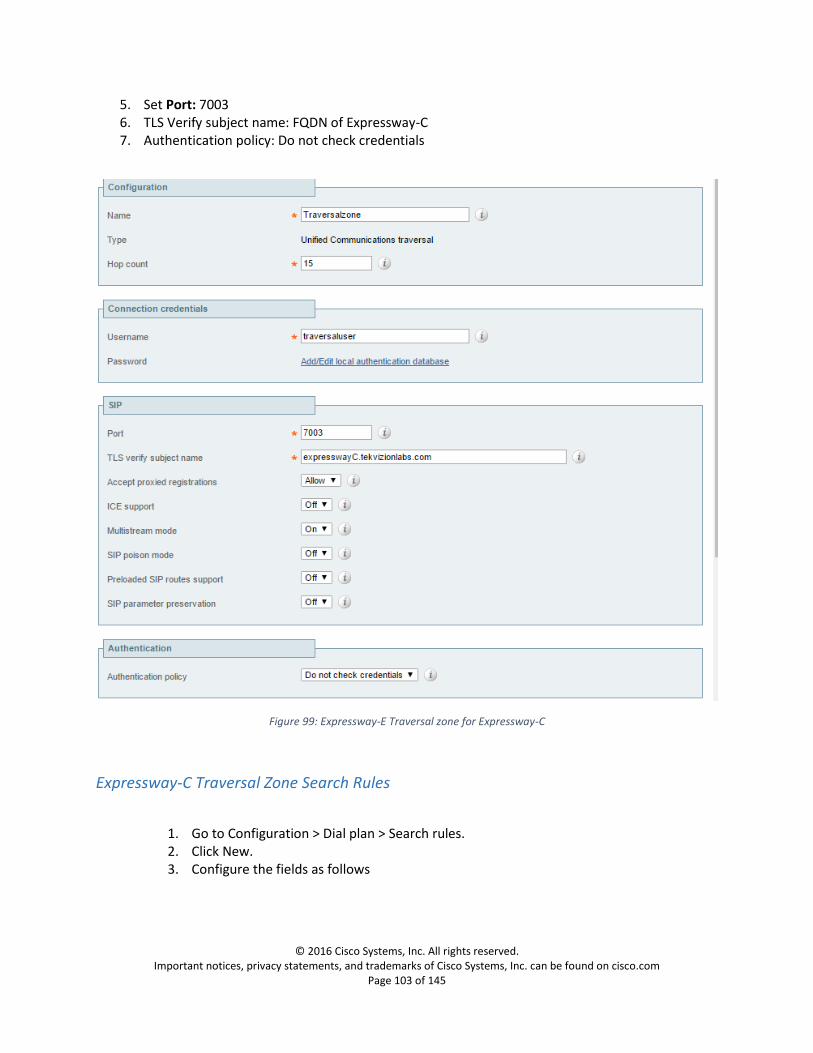
5. Set Port: 7003 6. TLS Verify subject name: FQDN of Expressway-C 7. Authentication policy: Do not check credentials
Figure 99: Expressway-E Traversal zone for Expressway-C
Expressway-C Traversal Zone Search Rules
1. Go to Configuration > Dial plan > Search rules. 2. Click New. 3. Configure the fields as follows

© 2016 Cisco Systems, Inc. All rights reserved. Important notices, privacy statements, and trademarks of Cisco Systems, Inc. can be found on cisco.com
Page 104 of 145
Figure 100: Expressway-C Traversal Zone Search rule for Expressway-E
Expressway-E Traversal Zone Search Rules
1. Go to Configuration > Dial plan > Search rules. 2. Click New. 3. Configure the fields as follows

© 2016 Cisco Systems, Inc. All rights reserved. Important notices, privacy statements, and trademarks of Cisco Systems, Inc. can be found on cisco.com
Page 105 of 145
Figure 101: Expressway-E Traversal Zone Search rule for Expressway-C
Configuring External (Unknown) IP Address Routing
The following configuration defines how an Expressway routes calls (and other requests) to external IP
addresses. An external IP address is an IP address which is not ‘known’ to the Expressway and therefore
assumed to be a publicly routable address.
Known IP addresses are addresses defined in a subzone (using a subzone membership subnet rule).
All requests destined for external IP addresses, originating at the Expressway-C are routed to the Expressway-E using a search rule.
The Expressway-E then attempts to open a connection directly to the IP address
To configure how the Expressway handles calls to unknown IP addresses:
1. Go to Configuration > Dial plan > Configuration. 2. Configure the fields as follows:
Expressway-C:

© 2016 Cisco Systems, Inc. All rights reserved. Important notices, privacy statements, and trademarks of Cisco Systems, Inc. can be found on cisco.com
Page 106 of 145
Figure 102: Expressway-C Dial Plan Configuration
Expressway-E:
Figure 103: Expressway-E Dial Plan Configuration
To create the search rules to route calls to IP addresses to the Expressway-E:
1. On the Expressway-C Go to Configuration > Dial plan > Search rules. 2. Click New. 3. Configure the fields as follows:
Figure 104: Expressway-C External IP address search rule
© 2016 Cisco Systems, Inc. All rights reserved. Important notices, privacy statements, and trademarks of Cisco Systems, Inc. can be found on cisco.com
Page 107 of 145
Discover Unified Communication Servers and Services
The Expressway-C must be configured with the address details of the Unified Communications
services/nodes that are going to provide registration, call control, provisioning, voicemail, messaging,
and presence services to MRA users.
Note: The connections configured in this procedure are static. You must refresh the configuration on the
Expressway-C after you reconfigure or upgrade any of the discovered Unified Communications nodes
Go to Configuration > Unified Communications > <UC server type> and click Refresh servers.
Trust the Certificates Presented to the Expressway-C
If TLS verify mode is On when discovering Unified Communications services, then you must configure
the Expressway-C to trust the certificates presented by the IM and Presence Service nodes and Unified
CM servers.
1. Determine the relevant CA certificates to upload:
If the servers' tomcat and Call Manager certificates are CA-signed, the Expressway-C's trusted CA list must include the root CA of the certificate issuer.
If the servers are using self-signed certificates, the Expressway-C's trusted CA list must include the self-signed certificates from all discovered IM and Presence Service nodes, Cisco Unity Connection servers, and Unified CM servers.
2. Upload the required certificates to the Expressway-C (Maintenance > Security certificates > Trusted CA certificate).
3. Restart the Expressway-C (Maintenance > Restart options).
Discover Unified CM Servers
1. On Expressway-C, go to Configuration > Unified Communications > Unified CM servers. The page lists any Unified CM nodes that have already been discovered

© 2016 Cisco Systems, Inc. All rights reserved. Important notices, privacy statements, and trademarks of Cisco Systems, Inc. can be found on cisco.com
Page 108 of 145
2. Add the details of a Unified CM publisher node
Click New.
Enter the Unified CM publisher address.
You must enter an FQDN when TLS verify mode is On.
Enter the Username and Password of an account that can access this server.
Note: These credentials are stored permanently in the Expressway database. The corresponding Unified CM user must have the Standard AXL API Access role.
[Recommended] Leave TLS verify mode switched On to ensure Expressway verifies the node's certificates.
The Unified CM node presents its tomcat certificate for AXL and UDS queries, and its Call Manager certificate for subsequent SIP traffic. If the Unified CM server is using self-signed certificates, the Expressway-C's trusted CA list must include a copy of the tomcat certificate and the Call Manager certificate from every Unified CM server.
Click Add address.
Set the TLS Verify mode to on, make sure the expressway-c and cucm certificates were signed by the CA.
If the secure connection test was successful, or if you did not enable TLS verify mode, then the system attempts to contact the publisher and retrieve details of its associated nodes.
Figure 105: Expressway-C Unified CM Servers
3. Repeat the discovery procedure for other Unified CM nodes/clusters, if required. 4. Click Refresh servers to refresh all the node details after configuring multiple publisher
addresses
Discover IM and Presence Service Nodes
1. On Expressway-C, go to Configuration > Unified Communications > IM and Presence Service nodes.
2. The page lists any IM and Presence Service nodes that have already been discovered. 3. Add the details of an IM and Presence Service database publisher node:
Click New.
Enter the address of the IM and Presence Service database publisher node.
You must enter an FQDN when TLS verify mode is On.

© 2016 Cisco Systems, Inc. All rights reserved. Important notices, privacy statements, and trademarks of Cisco Systems, Inc. can be found on cisco.com
Page 109 of 145
Enter the Username and Password of an account that can access this server.
Note: These credentials are stored permanently in the Expressway database. The corresponding IM and Presence Service user must have the Standard AXL API Access role.
[Recommended] Leave TLS verify mode switched On to ensure Expressway verifies the node's tomcat certificate (for XMPP-related communications).
[Optional] Select which deployment this node/cluster will belong to.
The Deployment field does not show if you have not created multiple deployments. All nodes belong to the default deployment if you choose not to use multiple deployments.
Click Add address.
If you enabled TLS verify mode, then the Expressway tests whether a secure connection can be established. It does this so you can find any TLS configuration errors before it continues the discovery process.
If the secure connection test was successful, or if you did not enable TLS verify mode, then the system attempts to contact the publisher and retrieve details of its associated nodes.
Figure 106: Expressway-C IM and Presence Service nodes
Note: The status of the discovered node will be Inactive unless a valid traversal zone connection exists
between the Expressway-C and the Expressway-E (may not yet be configured).
4. Repeat the discovery procedure for other IM and Presence Service nodes/clusters, if required. 5. Click Refresh servers to refresh all the node details after configuring multiple publisher
addresses.
Automatically Generated Zones and Search Rules
Expressway-C automatically generates non-configurable neighbor zones between itself and each
discovered Unified CM node. A TCP zone is always created, and a TLS zone is created also if the Unified
CM node is configured with a Cluster Security Mode (System > Enterprise Parameters > Security
Parameters) of 1 (Mixed) (so that it can support devices provisioned with secure profiles). The TLS zone
© 2016 Cisco Systems, Inc. All rights reserved. Important notices, privacy statements, and trademarks of Cisco Systems, Inc. can be found on cisco.com
Page 110 of 145
is configured with its TLS verify mode set to On if the Unified CM discovery had TLS verify mode enabled.
This means that the Expressway-C will verify the CallManager certificate for subsequent SIP
communications. Each zone is created with a name in the format 'CEtcp-<node name>' or 'CEtls-<node
name>'.
A non-configurable search rule, following the same naming convention, is also created automatically for
each zone. The rules are created with a priority of 45. If the Unified CM node that is targeted by the
search rule has a long name, the search rule will use a regex for its address pattern match.
IM&P Configuration
Loading Server and Trust Certificates IM&P Server should trust Skype for Business Front End Server.
IM&P Trusted CA Certificate Follow the steps described in Download a root certificate from CA to download the root certificate from
CA
Upload root Certificate
1. Set Certificate Purpose: cup-trust 2. The services Cisco SIP Proxy Service, Cisco Presence Engine must be restarted in order for the
changes to take effect:

© 2016 Cisco Systems, Inc. All rights reserved. Important notices, privacy statements, and trademarks of Cisco Systems, Inc. can be found on cisco.com
Page 111 of 145
Figure 107:IM&P-Upload Root Certificate
3. Click on the uploaded certificate and it should look similar to the one below

© 2016 Cisco Systems, Inc. All rights reserved. Important notices, privacy statements, and trademarks of Cisco Systems, Inc. can be found on cisco.com
Page 112 of 145
Figure 108:IM&P-Root Certificate Example

© 2016 Cisco Systems, Inc. All rights reserved. Important notices, privacy statements, and trademarks of Cisco Systems, Inc. can be found on cisco.com
Page 113 of 145
IM&P Server Certificate Navigation: Cisco Unified IM and Presence OS Administration/Security->Certificate Management
Generate CSR
1. Click on ‘Generate CSR’
Figure 109: IM&P Generate CSR-1
2. Set Certificate Purpose: Cup 3. Set Distribution: Select the IM&P publisher node 4. Set Key Length: 2048
Figure 110:IM&P Generate CSR-2

© 2016 Cisco Systems, Inc. All rights reserved. Important notices, privacy statements, and trademarks of Cisco Systems, Inc. can be found on cisco.com
Page 114 of 145
After the CSR is generated and downloaded, follow the steps described in Submit a certificate request in
the Certificate Authority to create a certificate request in CA.
Upload Certificate
5. Once the certificate is downloaded, click on ‘Upload Certificate/Certificate chain’ 6. Set Certificate Purpose: cup
Figure 111: IM&P-Upload Certificate-1
Figure 112:IM&P-Upload Certificate-2
7. Click on the uploaded certificate and it should look similar to the one below

© 2016 Cisco Systems, Inc. All rights reserved. Important notices, privacy statements, and trademarks of Cisco Systems, Inc. can be found on cisco.com
Page 115 of 145
Figure 113: IM&P-Server Certificate Example
Application Listeners Navigation: System->Application Listeners
Configure the default Cisco SIP Proxy TLS Listeners for Peer and Server Authentication as shown.

© 2016 Cisco Systems, Inc. All rights reserved. Important notices, privacy statements, and trademarks of Cisco Systems, Inc. can be found on cisco.com
Page 116 of 145
Figure 114:Cisco IM&P Application Listener - Peer Auth
Figure 115: Cisco IM&P Application Listener - Server Auth
© 2016 Cisco Systems, Inc. All rights reserved. Important notices, privacy statements, and trademarks of Cisco Systems, Inc. can be found on cisco.com
Page 117 of 145
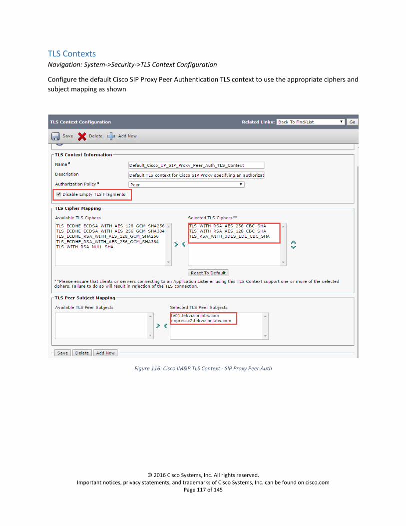
TLS Contexts Navigation: System->Security->TLS Context Configuration
Configure the default Cisco SIP Proxy Peer Authentication TLS context to use the appropriate ciphers and
subject mapping as shown
Figure 116: Cisco IM&P TLS Context - SIP Proxy Peer Auth
© 2016 Cisco Systems, Inc. All rights reserved. Important notices, privacy statements, and trademarks of Cisco Systems, Inc. can be found on cisco.com
Page 118 of 145
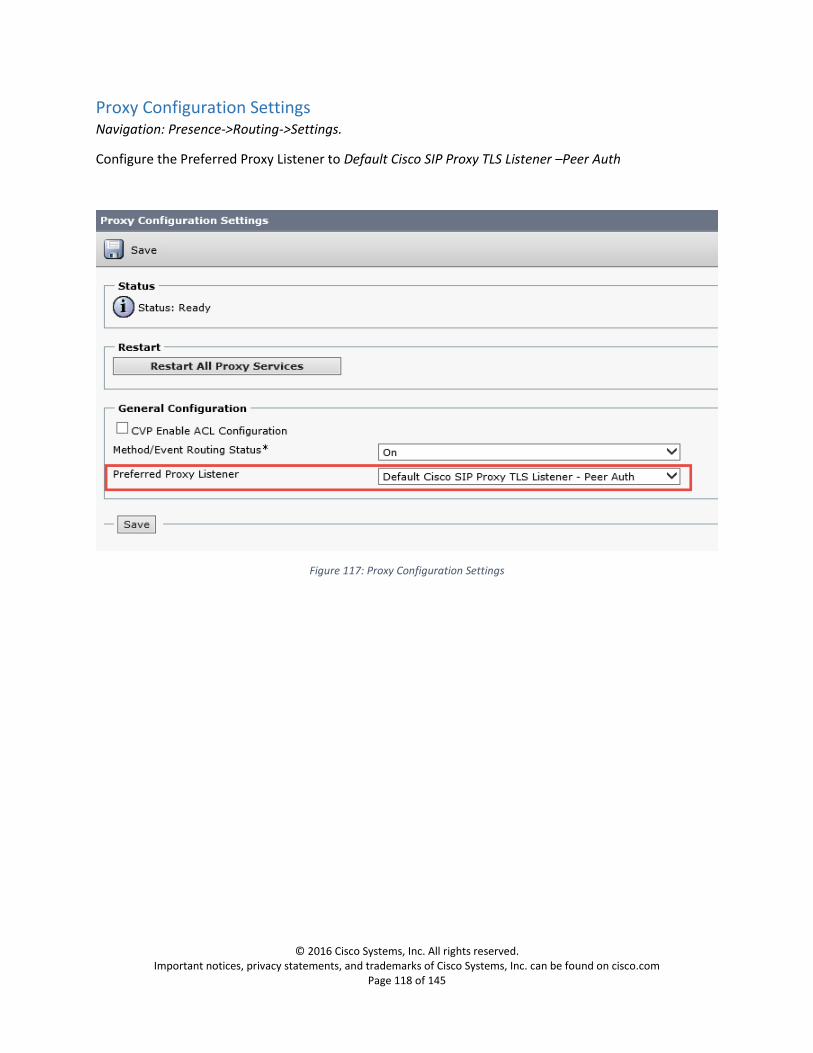
Proxy Configuration Settings Navigation: Presence->Routing->Settings.
Configure the Preferred Proxy Listener to Default Cisco SIP Proxy TLS Listener –Peer Auth
Figure 117: Proxy Configuration Settings

© 2016 Cisco Systems, Inc. All rights reserved. Important notices, privacy statements, and trademarks of Cisco Systems, Inc. can be found on cisco.com
Page 119 of 145
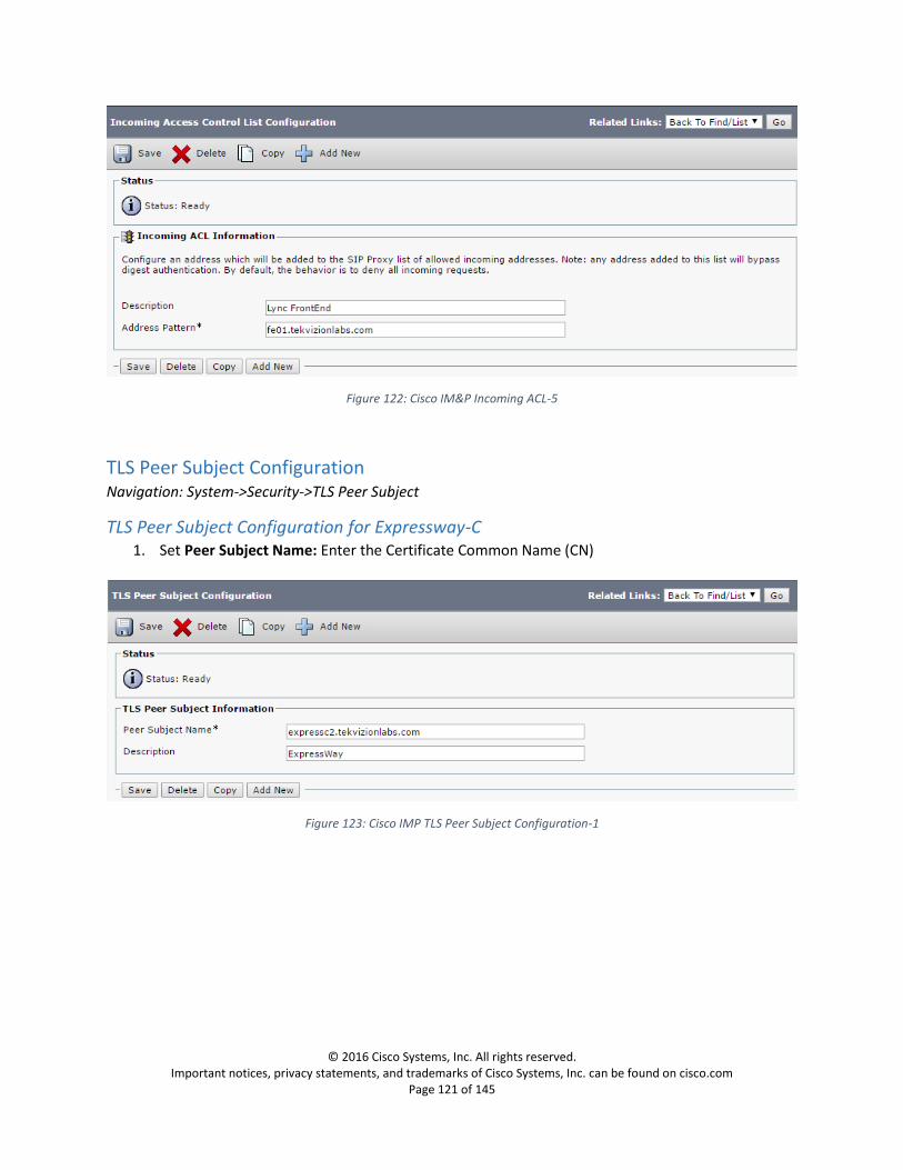
Incoming ACL Configuration Navigation: System->Security->Incoming ACL
Configure address patterns that control which incoming servers and domains can access the IM and
Presence Service without authentication
Incoming ACL connections Lists:
Skype for business internal clients
Expressway server’s
Skype for Business server’s
Figure 118: Cisco IM&P Incoming ACL-1
Figure 119: Cisco IM&P Incoming ACL-2

© 2016 Cisco Systems, Inc. All rights reserved. Important notices, privacy statements, and trademarks of Cisco Systems, Inc. can be found on cisco.com
Page 120 of 145
Figure 120: Cisco IM&P Incoming ACL-3
Figure 121: Cisco IM&P Incoming ACL-4
© 2016 Cisco Systems, Inc. All rights reserved. Important notices, privacy statements, and trademarks of Cisco Systems, Inc. can be found on cisco.com
Page 121 of 145
Figure 122: Cisco IM&P Incoming ACL-5
TLS Peer Subject Configuration Navigation: System->Security->TLS Peer Subject
TLS Peer Subject Configuration for Expressway-C 1. Set Peer Subject Name: Enter the Certificate Common Name (CN)
Figure 123: Cisco IMP TLS Peer Subject Configuration-1

© 2016 Cisco Systems, Inc. All rights reserved. Important notices, privacy statements, and trademarks of Cisco Systems, Inc. can be found on cisco.com
Page 122 of 145
TLS Peer Subject Configuration for Skype for Business Server 1. Set Peer Subject Name: Enter the Certificate Common Name (CN)
Figure 124: Cisco IMP TLS Peer Subject Configuration-2
Presence Gateway Configuration Navigation: Presence-> Gateways
Configure a Cisco Unified Communications Manager gateway
1. Set Presence Gateway Type: Choose the Cisco UCM to allow IM and Presence Service to receive ‘On the Phone’ availability information
2. Set Description: Enter a meaningful description that will help you to distinguish between presence gateway instances when you have configured more than one type of gateway
3. Set Presence Gateway: Enter the IP Address or FQDN of the Cisco Unified Communications Manager node
Figure 125: Cisco IM&P Presence Gateway

© 2016 Cisco Systems, Inc. All rights reserved. Important notices, privacy statements, and trademarks of Cisco Systems, Inc. can be found on cisco.com
Page 123 of 145
Presence Settings Configuration Navigation: Presence->Settings->Standard Configuration
Configure the Presence Settings to manage the global availability sharing capability for all clients that
connect to the IM and Presence Service.
1. Set Cluster ID: This unique identifier is automatically generated 2. Set CUCM IM and Presence Publish Trunk: Select the appropriate IM and Presence Service SIP
trunk required for phone availability integration. This is the trunk configured in Cisco UCM for IM and Presence Server at Devices -> Trunk.
3. Confirm Enable Partitioned Intra-domain Federation with LCS/OCS/Lync: is checked 4. Set Partitioned Intra-domain Routing Mode: Advanced Routing Mode
Figure 126: Cisco IM&P Presence Settings

© 2016 Cisco Systems, Inc. All rights reserved. Important notices, privacy statements, and trademarks of Cisco Systems, Inc. can be found on cisco.com
Page 124 of 145
Security Settings Configuration Navigation: System->Security->Settings
1. Set SIP Intra-cluster Proxy-to-Proxy Transport Protocol: TCP
Figure 127: Cisco IM&P Security Settings

© 2016 Cisco Systems, Inc. All rights reserved. Important notices, privacy statements, and trademarks of Cisco Systems, Inc. can be found on cisco.com
Page 125 of 145
Static Route to Front End Configuration Navigation: Presence->Routing->Static Routes
A static route is a fixed path through the network, unlike a dynamic route path that automatically
calculates according to routing protocols and routing update messages
1. Set Destination Pattern: Enter the pattern of the static route 2. Set Next Hop: Enter the IP address or FQDN of the next hop for the static route. 3. Set Next Hop Port: 5061 4. Set Route Type: Domain 5. Set Protocol Type: TLS
Figure 128: Cisco IM&P Static Route

© 2016 Cisco Systems, Inc. All rights reserved. Important notices, privacy statements, and trademarks of Cisco Systems, Inc. can be found on cisco.com
Page 126 of 145
Skype for Business Server Configuration Skype for Business Server should trust Expressway.
Add Expressway-C to Skype for Business Topology Intra-domain federation requires the following configuration on Skype for Business.
Expressway-C as a trusted application server
In general, the steps to create the trusted application servers is similar to Expressway-C whether using
Enterprise or Standard Edition Skype for Business Sever. The steps below outline the overall procedure
using the Skype for Business Power Shell.
Trusted Application Server – Expressway-C
a. Create the trusted application pool by running the following command. Use Get-CsPool to verify FQDN of the Registrar. New-CsTrustedApplicationPool -Identity expressc2.tekvizionlabs.com –Registrar fe01.tekvizionlabs.com –Site CleanDefaultTopology –TreatAsAuthenticated $true –ThrottleAsServer $true –RequiresReplication $false –Outboundonly $false -ComputerFqdn expressc2.tekvizionlabs.com Identity – Name of the trusted application pool Registrar – ServiceID or FQDN of registrar service for the pool Site – Name of the site where you want the pool to be created ComputerFQDN – FQDN of the Expressway-C (used only if using Enterprise Edition Skype for Business)
b. The following command is used to add additional computers to the trusted application if using Enterprise pools. This step can be skipped if using Standard Edition Skype for Business. New-CsTrustedApplicationComputer -Identity expressc3.tekvizionlabs.com -Pool expressc2.tekvizionlabs.com Identity – FQDN of the new server being added to the trusted application pool (Enterprise Edition Skype for Business) Pool – FQDN of the trusted application pool
c. Finally, create a new trusted application and add to the above created application pool, using port 5061 New-CsTrustedApplication -ApplicationId ExpresswaycApplication1 -TrustedApplicationPoolFqdn expressc2.tekvizionlabs.com -Port 65072 ApplicationID – Name of the application. Can be any name TrustedApplicationPoolFQDN – FQDN of the trusted application pool Port: Listening port (65072 for TLS)
d. Publish the topology Enable-CsTopology

© 2016 Cisco Systems, Inc. All rights reserved. Important notices, privacy statements, and trademarks of Cisco Systems, Inc. can be found on cisco.com
Page 127 of 145
The configuration can be quickly verified as shown below.
Figure 129: Skype for Business Static Route to Expressway-C
Static Route Configuration for federation
In the Skype for Business Management Shell, use the below commands to create a new static route
variable on Skype for Business for federation and then add the route variable to the global static routing
configuration collection
$route=New-CsStaticRoute -TLSRoute -Destination "expressc2.tekvizionlabs.com" -MatchUri
"tekvizionlabs.com" -Port 5061 -UseDefaultCertificate $true
Set-CsStaticRoutingConfiguration -Identity global -Route @{Add=$route}
Destination - FQDN of the Expressway-C
Port – Listening port (usually 5061 for TLS)
MatchUri – Destination domain
Verify the configured static routes.

© 2016 Cisco Systems, Inc. All rights reserved. Important notices, privacy statements, and trademarks of Cisco Systems, Inc. can be found on cisco.com
Page 128 of 145
Get-CsStaticRoutingConfiguration | Select-Object -ExpandProperty route
Figure 130: Skype for Business Static Route to Expressway-C
Configure Encryption Level Configure Encryption level parameters through the Windows PowerShell® command line interface
because they are not configurable on Skype for Business Server Control Panel
Media EncryptionLevel must be set to Require Encryption.
Set-CsMediaConfiguration –identity Global -EncryptionLevel RequireEncryption
Figure 131: Skype for Business Server – Media Configuration

© 2016 Cisco Systems, Inc. All rights reserved. Important notices, privacy statements, and trademarks of Cisco Systems, Inc. can be found on cisco.com
Page 129 of 145
Trusted Application Server – IM&P Nodes
Add IM&P Publisher as Trusted Application Server
a. Create the trusted application pool by running the following command. Use Get-CsPool to verify FQDN of the Registrar. New-CsTrustedApplicationPool -Identity clus30pimp.tekvizionlabs.com –Registrar fe01.tekvizionlabs.com –Site CleanDefaultTopology –TreatAsAuthenticated $true –ThrottleAsServer $true –RequiresReplication $false –Outboundonly $false -ComputerFqdn clus30pimp.tekvizionlabs.com Identity – Name of the trusted application pool Registrar – ServiceID or FQDN of registrar service for the pool Site – Name of the site where you want the pool to be created ComputerFQDN – FQDN of the Cisco IM&P publisher (used only if using Enterprise Edition Skype for Business)
b. The following command is used to add additional peers to the trusted application pool. New-CsTrustedApplicationComputer -Identity clus30pimp.tekvizionlabs.com -Pool clus30pimp.tekvizionlabs.com Identity – FQDN of the new server being added to the trusted application pool (Enterprise Edition SFB) Pool – FQDN of the trusted application pool
c. Finally, create a new trusted application and add to the above created application pool, using port 5061 New-CsTrustedApplication -ApplicationId impapplication1 -TrustedApplicationPoolFqdn clus30pimp.tekvizionlabs.com -Port 5061 ApplicationID – Name of the application. Can be any name TrustedApplicationPoolFQDN – FQDN of the trusted application pool Port: Listening port (5061 for TLS)
d. Publish the topology Enable-CsTopology
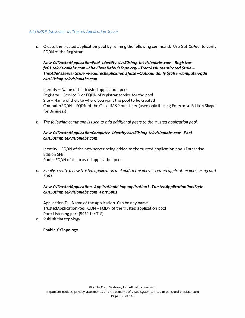
© 2016 Cisco Systems, Inc. All rights reserved. Important notices, privacy statements, and trademarks of Cisco Systems, Inc. can be found on cisco.com
Page 130 of 145
Add IM&P Subscriber as Trusted Application Server
a. Create the trusted application pool by running the following command. Use Get-CsPool to verify FQDN of the Registrar. New-CsTrustedApplicationPool -Identity clus30simp.tekvizionlabs.com –Registrar fe01.tekvizionlabs.com –Site CleanDefaultTopology –TreatAsAuthenticated $true –ThrottleAsServer $true –RequiresReplication $false –Outboundonly $false -ComputerFqdn clus30simp.tekvizionlabs.com Identity – Name of the trusted application pool Registrar – ServiceID or FQDN of registrar service for the pool Site – Name of the site where you want the pool to be created ComputerFQDN – FQDN of the Cisco IM&P publisher (used only if using Enterprise Edition Skype for Business)
b. The following command is used to add additional peers to the trusted application pool. New-CsTrustedApplicationComputer -Identity clus30simp.tekvizionlabs.com -Pool clus30simp.tekvizionlabs.com Identity – FQDN of the new server being added to the trusted application pool (Enterprise Edition SFB) Pool – FQDN of the trusted application pool
c. Finally, create a new trusted application and add to the above created application pool, using port 5061 New-CsTrustedApplication -ApplicationId impapplication1 -TrustedApplicationPoolFqdn clus30simp.tekvizionlabs.com -Port 5061 ApplicationID – Name of the application. Can be any name TrustedApplicationPoolFQDN – FQDN of the trusted application pool Port: Listening port (5061 for TLS)
d. Publish the topology Enable-CsTopology

© 2016 Cisco Systems, Inc. All rights reserved. Important notices, privacy statements, and trademarks of Cisco Systems, Inc. can be found on cisco.com
Page 131 of 145
Update Skype for Business Certificates Using the Skype for Business Deployment Wizard update the Skype for Business Certificates with both
Server and Client Authentication
Figure 132: Skype for Business Deployment Wizard- Request & Assign Certificates-1

© 2016 Cisco Systems, Inc. All rights reserved. Important notices, privacy statements, and trademarks of Cisco Systems, Inc. can be found on cisco.com
Page 132 of 145
Figure 133: Skype for Business Deployment Wizard- Request & Assign Certificates-2

© 2016 Cisco Systems, Inc. All rights reserved. Important notices, privacy statements, and trademarks of Cisco Systems, Inc. can be found on cisco.com
Page 133 of 145
Figure 134: Skype for Business Deployment Wizard- Request & Assign Certificates-3

© 2016 Cisco Systems, Inc. All rights reserved. Important notices, privacy statements, and trademarks of Cisco Systems, Inc. can be found on cisco.com
Page 134 of 145
Figure 135: Skype for Business Deployment Wizard- Request & Assign Certificates-4

© 2016 Cisco Systems, Inc. All rights reserved. Important notices, privacy statements, and trademarks of Cisco Systems, Inc. can be found on cisco.com
Page 135 of 145
Figure 136: Skype for Business Deployment Wizard- Request & Assign Certificates-5

© 2016 Cisco Systems, Inc. All rights reserved. Important notices, privacy statements, and trademarks of Cisco Systems, Inc. can be found on cisco.com
Page 136 of 145
Figure 137: Skype for Business Deployment Wizard- Request & Assign Certificates-6

© 2016 Cisco Systems, Inc. All rights reserved. Important notices, privacy statements, and trademarks of Cisco Systems, Inc. can be found on cisco.com
Page 137 of 145
Figure 138: Skype for Business Deployment Wizard- Request & Assign Certificates-7

© 2016 Cisco Systems, Inc. All rights reserved. Important notices, privacy statements, and trademarks of Cisco Systems, Inc. can be found on cisco.com
Page 138 of 145
Figure 139: Skype for Business Deployment Wizard- Request & Assign Certificates-8

© 2016 Cisco Systems, Inc. All rights reserved. Important notices, privacy statements, and trademarks of Cisco Systems, Inc. can be found on cisco.com
Page 139 of 145
1. Enter the Organization Information 2. Enter the Geographical Information 3. Select the sip domain
Figure 140: Skype for Business Deployment Wizard- Request & Assign Certificates-9
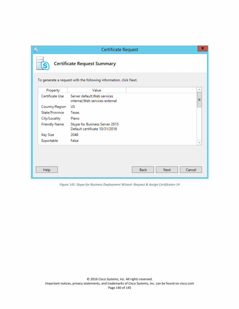
© 2016 Cisco Systems, Inc. All rights reserved. Important notices, privacy statements, and trademarks of Cisco Systems, Inc. can be found on cisco.com
Page 140 of 145
Figure 141: Skype for Business Deployment Wizard- Request & Assign Certificates-14
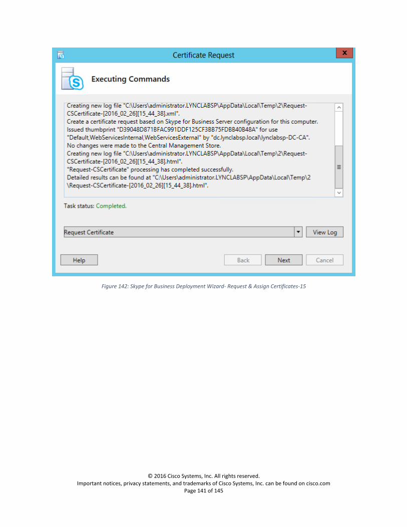
© 2016 Cisco Systems, Inc. All rights reserved. Important notices, privacy statements, and trademarks of Cisco Systems, Inc. can be found on cisco.com
Page 141 of 145
Figure 142: Skype for Business Deployment Wizard- Request & Assign Certificates-15

© 2016 Cisco Systems, Inc. All rights reserved. Important notices, privacy statements, and trademarks of Cisco Systems, Inc. can be found on cisco.com
Page 142 of 145
Figure 143: Skype for Business Deployment Wizard- Request & Assign Certificates-16
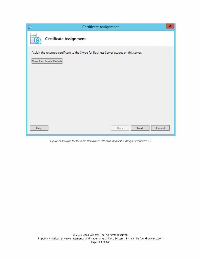
© 2016 Cisco Systems, Inc. All rights reserved. Important notices, privacy statements, and trademarks of Cisco Systems, Inc. can be found on cisco.com
Page 143 of 145
Figure 144: Skype for Business Deployment Wizard- Request & Assign Certificates-18
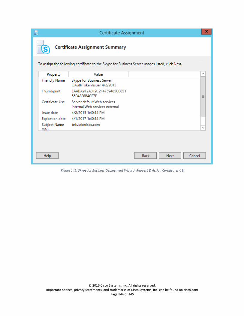
© 2016 Cisco Systems, Inc. All rights reserved. Important notices, privacy statements, and trademarks of Cisco Systems, Inc. can be found on cisco.com
Page 144 of 145
Figure 145: Skype for Business Deployment Wizard- Request & Assign Certificates-19

© 2016 Cisco Systems, Inc. All rights reserved. Important notices, privacy statements, and trademarks of Cisco Systems, Inc. can be found on cisco.com
Page 145 of 145
Figure 146: Skype for Business Deployment Wizard- Request & Assign Certificates-20
Related Documents