Audio Processing Algorithms Implemented in Tempo Semiconductor Consumer Audio Products Tempo Semiconductor © 2014

Welcome message from author
This document is posted to help you gain knowledge. Please leave a comment to let me know what you think about it! Share it to your friends and learn new things together.
Transcript
Audio Processing Algorithms
Implemented in Tempo Semiconductor
Consumer Audio Products
Tempo Semiconductor
© 2014
1.0 Purpose
The purpose of this application note is to help the system designer understand the
audio processing algorithms that are available in the ACS422xx and ACS62200
consumer audio products from Tempo Semiconductor.
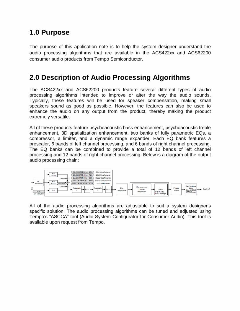
2.0 Description of Audio Processing Algorithms The ACS422xx and ACS62200 products feature several different types of audio processing algorithms intended to improve or alter the way the audio sounds. Typically, these features will be used for speaker compensation, making small speakers sound as good as possible. However, the features can also be used to enhance the audio on any output from the product, thereby making the product extremely versatile. All of these products feature psychoacoustic bass enhancement, psychoacoustic treble enhancement, 3D spatialization enhancement, two banks of fully parametric EQs, a compressor, a limiter, and a dynamic range expander. Each EQ bank features a prescaler, 6 bands of left channel processing, and 6 bands of right channel processing. The EQ banks can be combined to provide a total of 12 bands of left channel processing and 12 bands of right channel processing. Below is a diagram of the output audio processing chain:
All of the audio processing algorithms are adjustable to suit a system designer’s specific solution. The audio processing algorithms can be tuned and adjusted using Tempo’s “ASCCA” tool (Audio System Configurator for Consumer Audio). This tool is available upon request from Tempo.

3.0 Prior to Adjusting Any Algorithms When opening ASCCA, it is important to right click on the “ASC.exe” executable and choose “Run As Administrator”. As ASCCA begins to load, the designer will be asked to load an “*.i2c” file. This is a text based file that can be used to automatically write registers as ASCCA begins loading. For an example of this type file, please contact your Tempo representative. Because Tempo’s audio algorithms operate in the frequency domain, it is important that the audio processor’s values match the sampling rate of the audio content. Since the sampling rate is determined by the system design (via the I2S clock rates), the ASCCA tool allows the system designer to set the tool so that all values are calculated properly. To set the sampling rate once ASCCA is opened, click “System” in the menu choices and choose “Set Sample Rate”. There, the system designer can choose one of the supported sampling rates:
Note that if the sampling rate set in the tool does not match the incoming audio content, then the frequency values appearing in the tool will not be the exact frequencies affected by the algorithms.
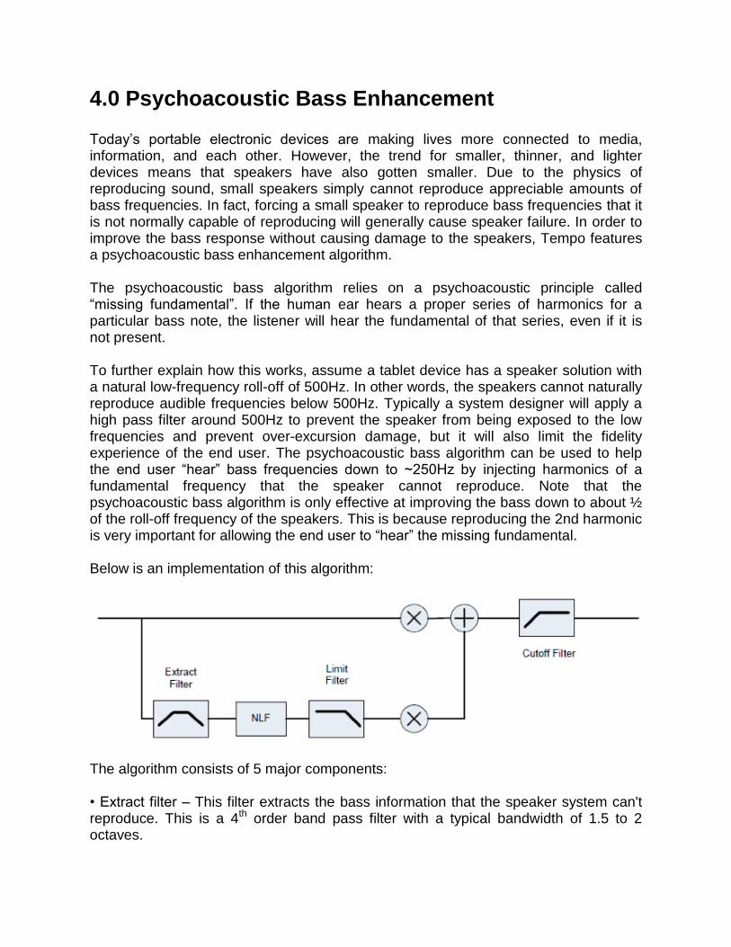
4.0 Psychoacoustic Bass Enhancement Today’s portable electronic devices are making lives more connected to media, information, and each other. However, the trend for smaller, thinner, and lighter devices means that speakers have also gotten smaller. Due to the physics of reproducing sound, small speakers simply cannot reproduce appreciable amounts of bass frequencies. In fact, forcing a small speaker to reproduce bass frequencies that it is not normally capable of reproducing will generally cause speaker failure. In order to improve the bass response without causing damage to the speakers, Tempo features a psychoacoustic bass enhancement algorithm. The psychoacoustic bass algorithm relies on a psychoacoustic principle called “missing fundamental”. If the human ear hears a proper series of harmonics for a particular bass note, the listener will hear the fundamental of that series, even if it is not present. To further explain how this works, assume a tablet device has a speaker solution with a natural low-frequency roll-off of 500Hz. In other words, the speakers cannot naturally reproduce audible frequencies below 500Hz. Typically a system designer will apply a high pass filter around 500Hz to prevent the speaker from being exposed to the low frequencies and prevent over-excursion damage, but it will also limit the fidelity experience of the end user. The psychoacoustic bass algorithm can be used to help the end user “hear” bass frequencies down to ~250Hz by injecting harmonics of a fundamental frequency that the speaker cannot reproduce. Note that the psychoacoustic bass algorithm is only effective at improving the bass down to about ½ of the roll-off frequency of the speakers. This is because reproducing the 2nd harmonic is very important for allowing the end user to “hear” the missing fundamental. Below is an implementation of this algorithm:
The algorithm consists of 5 major components: • Extract filter – This filter extracts the bass information that the speaker system can't reproduce. This is a 4th order band pass filter with a typical bandwidth of 1.5 to 2 octaves.
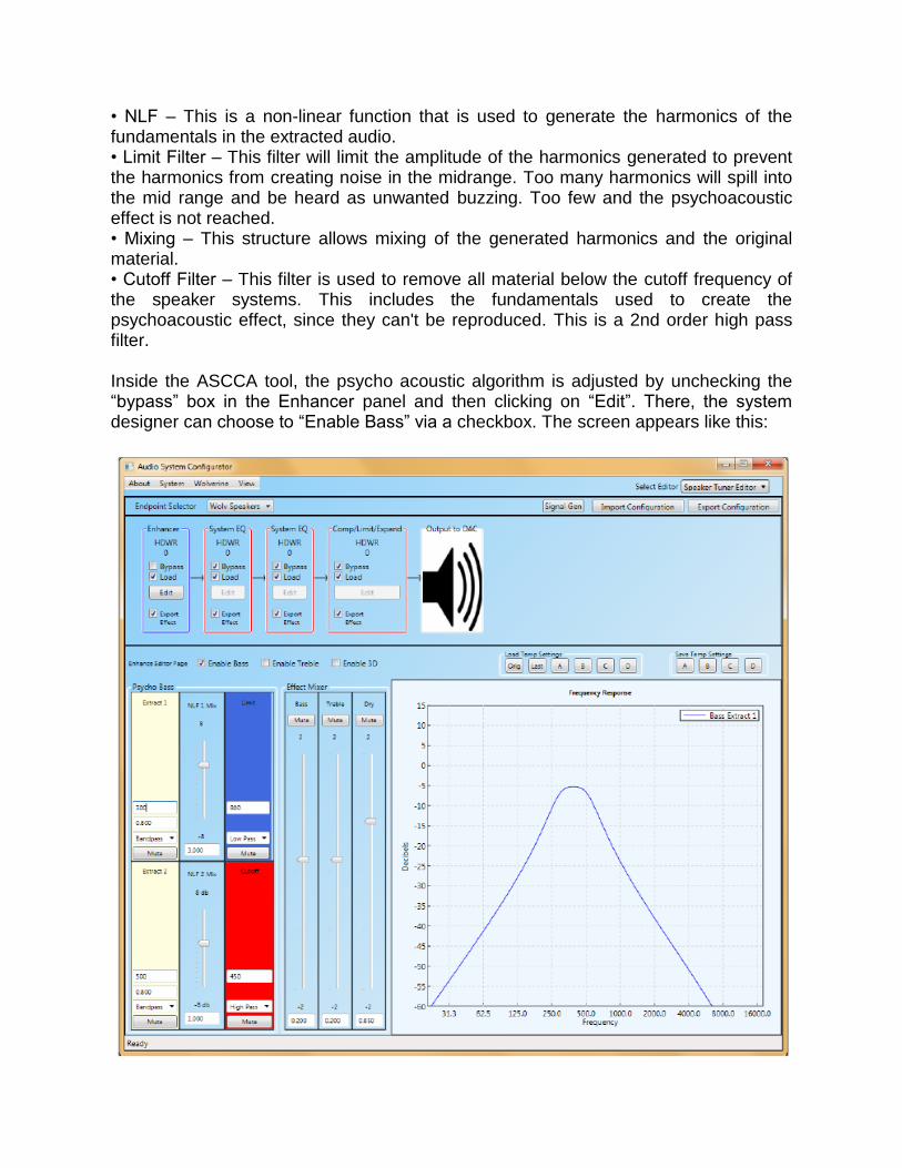
• NLF – This is a non-linear function that is used to generate the harmonics of the fundamentals in the extracted audio. • Limit Filter – This filter will limit the amplitude of the harmonics generated to prevent the harmonics from creating noise in the midrange. Too many harmonics will spill into the mid range and be heard as unwanted buzzing. Too few and the psychoacoustic effect is not reached. • Mixing – This structure allows mixing of the generated harmonics and the original material. • Cutoff Filter – This filter is used to remove all material below the cutoff frequency of the speaker systems. This includes the fundamentals used to create the psychoacoustic effect, since they can't be reproduced. This is a 2nd order high pass filter. Inside the ASCCA tool, the psycho acoustic algorithm is adjusted by unchecking the “bypass” box in the Enhancer panel and then clicking on “Edit”. There, the system designer can choose to “Enable Bass” via a checkbox. The screen appears like this:
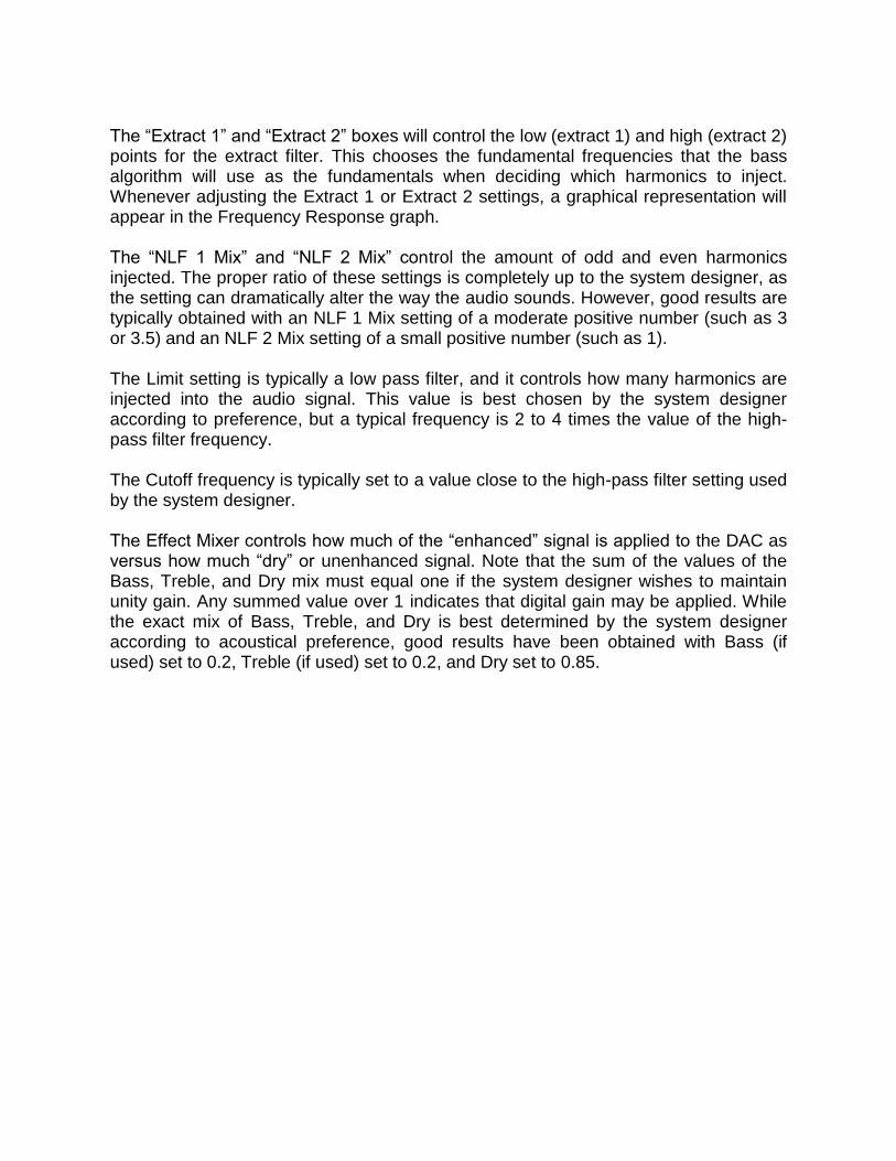
The “Extract 1” and “Extract 2” boxes will control the low (extract 1) and high (extract 2) points for the extract filter. This chooses the fundamental frequencies that the bass algorithm will use as the fundamentals when deciding which harmonics to inject. Whenever adjusting the Extract 1 or Extract 2 settings, a graphical representation will appear in the Frequency Response graph. The “NLF 1 Mix” and “NLF 2 Mix” control the amount of odd and even harmonics injected. The proper ratio of these settings is completely up to the system designer, as the setting can dramatically alter the way the audio sounds. However, good results are typically obtained with an NLF 1 Mix setting of a moderate positive number (such as 3 or 3.5) and an NLF 2 Mix setting of a small positive number (such as 1). The Limit setting is typically a low pass filter, and it controls how many harmonics are injected into the audio signal. This value is best chosen by the system designer according to preference, but a typical frequency is 2 to 4 times the value of the high-pass filter frequency. The Cutoff frequency is typically set to a value close to the high-pass filter setting used by the system designer. The Effect Mixer controls how much of the “enhanced” signal is applied to the DAC as versus how much “dry” or unenhanced signal. Note that the sum of the values of the Bass, Treble, and Dry mix must equal one if the system designer wishes to maintain unity gain. Any summed value over 1 indicates that digital gain may be applied. While the exact mix of Bass, Treble, and Dry is best determined by the system designer according to acoustical preference, good results have been obtained with Bass (if used) set to 0.2, Treble (if used) set to 0.2, and Dry set to 0.85.
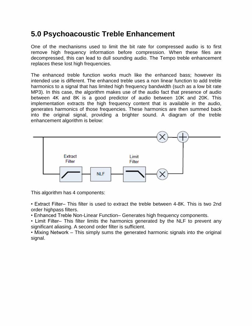
5.0 Psychoacoustic Treble Enhancement One of the mechanisms used to limit the bit rate for compressed audio is to first remove high frequency information before compression. When these files are decompressed, this can lead to dull sounding audio. The Tempo treble enhancement replaces these lost high frequencies. The enhanced treble function works much like the enhanced bass; however its intended use is different. The enhanced treble uses a non linear function to add treble harmonics to a signal that has limited high frequency bandwidth (such as a low bit rate MP3). In this case, the algorithm makes use of the audio fact that presence of audio between 4K and 8K is a good predictor of audio between 10K and 20K. This implementation extracts the high frequency content that is available in the audio, generates harmonics of those frequencies. These harmonics are then summed back into the original signal, providing a brighter sound. A diagram of the treble enhancement algorithm is below:
This algorithm has 4 components: • Extract Filter– This filter is used to extract the treble between 4-8K. This is two 2nd order highpass filters. • Enhanced Treble Non-Linear Function– Generates high frequency components. • Limit Filter– This filter limits the harmonics generated by the NLF to prevent any significant aliasing. A second order filter is sufficient. • Mixing Network – This simply sums the generated harmonic signals into the original signal.
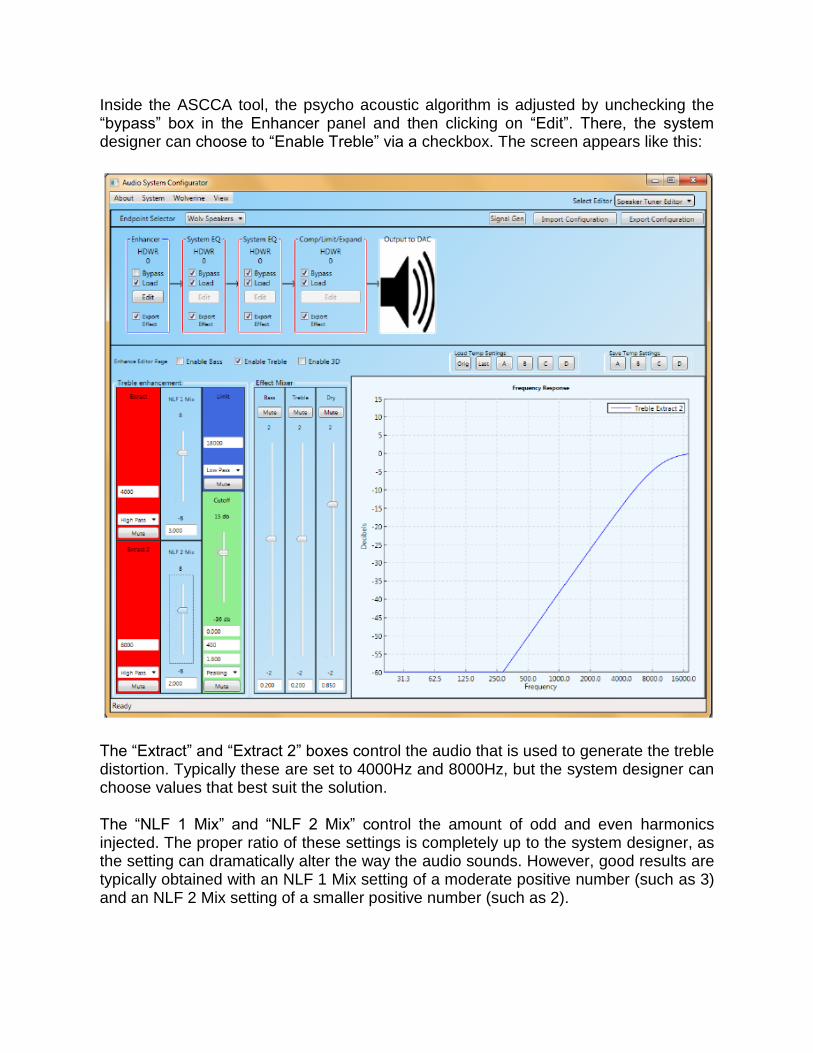
Inside the ASCCA tool, the psycho acoustic algorithm is adjusted by unchecking the “bypass” box in the Enhancer panel and then clicking on “Edit”. There, the system designer can choose to “Enable Treble” via a checkbox. The screen appears like this:
The “Extract” and “Extract 2” boxes control the audio that is used to generate the treble distortion. Typically these are set to 4000Hz and 8000Hz, but the system designer can choose values that best suit the solution. The “NLF 1 Mix” and “NLF 2 Mix” control the amount of odd and even harmonics injected. The proper ratio of these settings is completely up to the system designer, as the setting can dramatically alter the way the audio sounds. However, good results are typically obtained with an NLF 1 Mix setting of a moderate positive number (such as 3) and an NLF 2 Mix setting of a smaller positive number (such as 2).

The “Limit” box controls how many high the harmonics are inserted into the frequency band. Typically this is set to 18,000Hz to prevent aliasing that can cause the speakers to sound harsh. The “Cutoff” box is not used in this application. Leave the default settings. As described in detail in the Psychoacoustic Bass section, the “Effect Mixer” controls how much of the “enhanced” signal is applied to the DAC as versus how much “dry” or unenhanced signal. While the exact mix of Bass, Treble, and Dry is best determined by the system designer according to acoustical preference, good results have been obtained with Bass (if used) set to 0.2, Treble (if used) set to 0.2, and Dry set to 0.85.
6.0 3D Spatialization Enahncement
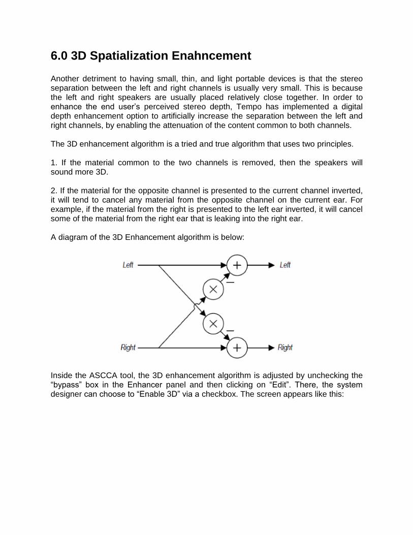
Another detriment to having small, thin, and light portable devices is that the stereo separation between the left and right channels is usually very small. This is because the left and right speakers are usually placed relatively close together. In order to enhance the end user’s perceived stereo depth, Tempo has implemented a digital depth enhancement option to artificially increase the separation between the left and right channels, by enabling the attenuation of the content common to both channels. The 3D enhancement algorithm is a tried and true algorithm that uses two principles. 1. If the material common to the two channels is removed, then the speakers will sound more 3D. 2. If the material for the opposite channel is presented to the current channel inverted, it will tend to cancel any material from the opposite channel on the current ear. For example, if the material from the right is presented to the left ear inverted, it will cancel some of the material from the right ear that is leaking into the right ear. A diagram of the 3D Enhancement algorithm is below:
Inside the ASCCA tool, the 3D enhancement algorithm is adjusted by unchecking the “bypass” box in the Enhancer panel and then clicking on “Edit”. There, the system designer can choose to “Enable 3D” via a checkbox. The screen appears like this:
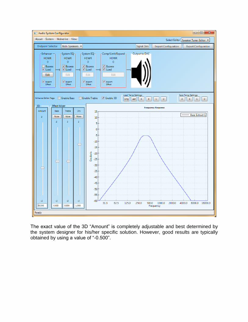
The exact value of the 3D “Amount” is completely adjustable and best determined by the system designer for his/her specific solution. However, good results are typically obtained by using a value of “-0.500”.

7.0 Parametric Equalization Algorithms Tempo’s ACS422xx and ACS62200 products feature two banks of 12 fully parametric EQ bands (6 for the left channel and 6 for the right channel) with a prescale function. The EQ banks are very flexible, allowing for use of both banks simultaneously on one output path, or allowing for one bank to be dedicated to the amplifier path and the second bank to be dedicated to the headphone path. Additionally, the system designer can choose how many EQ bands to enable for each bank. Please refer to the product’s datasheet for further instructions on these features. A graphical representation of each EQ bank is as follows:
Each EQ filter is a 6-Tap IIR Bi-quadratic filter. The figure below shows the structure of a single EQ filter. The a(0) tap is always normalized to be equal to 1 (400000h). The remaining 5 taps are 24-bit twos compliment format programmable coefficients. (-2 = coefficient < +2).
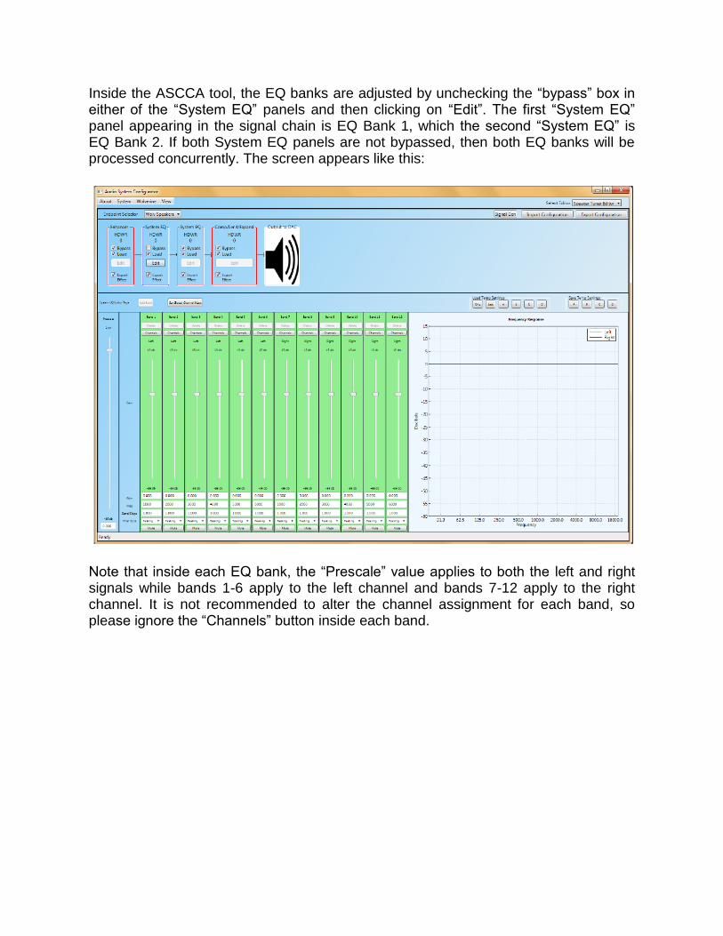
Inside the ASCCA tool, the EQ banks are adjusted by unchecking the “bypass” box in either of the “System EQ” panels and then clicking on “Edit”. The first “System EQ” panel appearing in the signal chain is EQ Bank 1, which the second “System EQ” is EQ Bank 2. If both System EQ panels are not bypassed, then both EQ banks will be processed concurrently. The screen appears like this:
Note that inside each EQ bank, the “Prescale” value applies to both the left and right signals while bands 1-6 apply to the left channel and bands 7-12 apply to the right channel. It is not recommended to alter the channel assignment for each band, so please ignore the “Channels” button inside each band.
The Prescale value is intended to be a digital attenuator that attenuates the digital signal prior to any EQ processing. Since the EQ is a digital function, it is highly recommended to use only attenuation in the EQ bands to avoid exceeding digital full scale. However, some situations may arise where gain is desired in a specific frequency band. In this case, Tempo recommends that the prescale be set to a negative value whose absolute value is greater than or equal to the largest amount of positive gain existing in the EQ bands. Please note that Tempo recommends setting the Prescale value to “-2dB” even if the
EQ bands are attenuation only. This helps prevent any digital clipping that might occur
due to artifacts in the IIR filters. In order to offset the 2dB decimation in the prescale,
+2dB of gain can be applied either in one of the EQ bands, the compressor’s make-up
gain, or in the gain value for the speaker or headphone output.
Each EQ band can be assigned one of 8 different functions: • Peaking – The most common form of equalization filter, a peaking filter allows you to emphasize or attenuate specific frequencies. Tempo’s peaking filters have adjustable center frequencies, adjustable gain or attenuation, and adjustable bandwidth. • Low Shelf – This is a common shelving filter that allows the system designer to choose a specific frequency and then attenuate or gain the content below that chosen frequency. • High Shelf – This is a common shelving filter that allows the system designer to choose a specific frequency and then attenuate or gain the content above that chosen frequency. • Low Pass – This is a 2nd order low pass filter with an adjustable -3dB frequency. • High pass – This is a 2nd order high pass filter with an adjustable 3dB frequency. • Bandpass – This is a bandpass filter with an adjustable center frequency and adjustable bandwidth. • Notch – Similar to a peaking filter with a very narrow bandwidth, the notch filter is typically used to filter out a very specific frequency, such as AC line noise. • Gain – This is a filter that applies a universal gain or attenuation to the incoming content. If the system designer is more familiar with using Q Factor instead of bandwidth, then he/she can convert the bandwidth values into a “Q” value using the following equation:
Q = f0/BW, where f0 is the center frequency of the filter
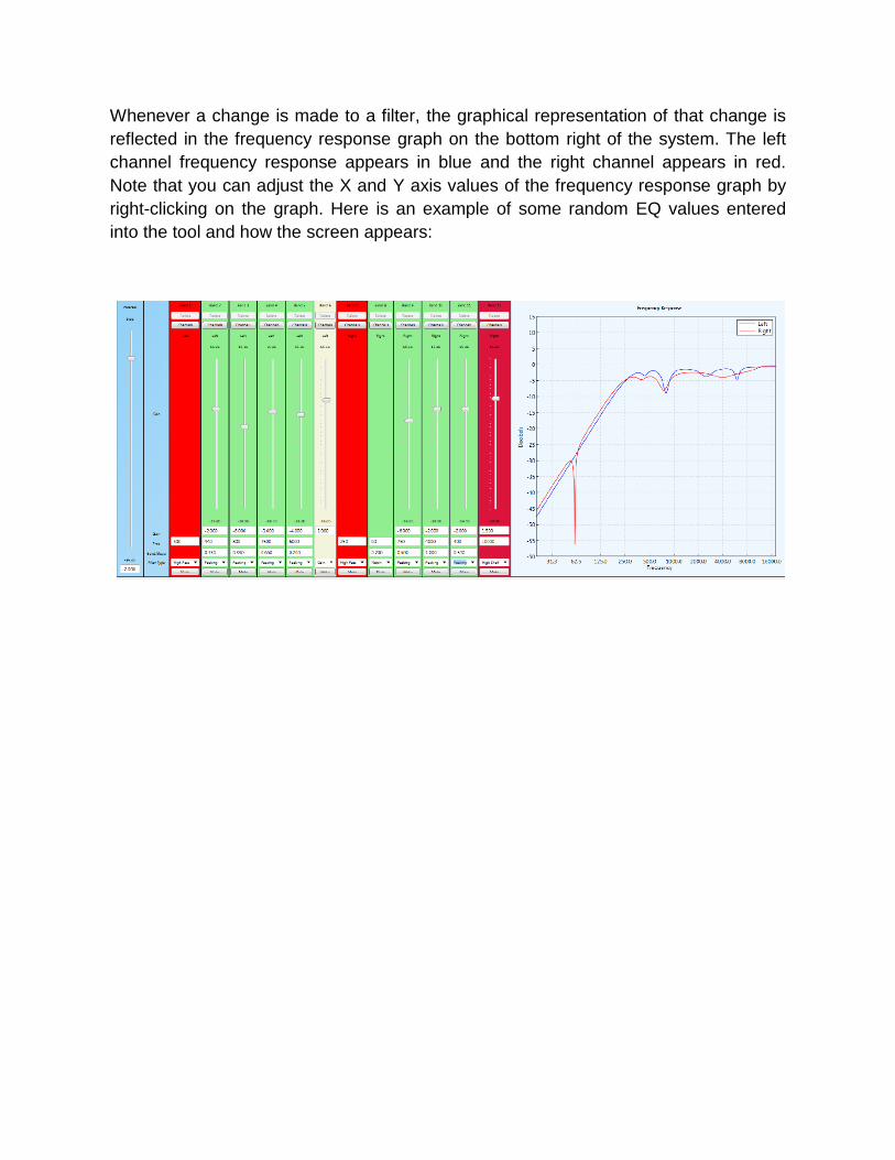
Whenever a change is made to a filter, the graphical representation of that change is
reflected in the frequency response graph on the bottom right of the system. The left
channel frequency response appears in blue and the right channel appears in red.
Note that you can adjust the X and Y axis values of the frequency response graph by
right-clicking on the graph. Here is an example of some random EQ values entered
into the tool and how the screen appears:
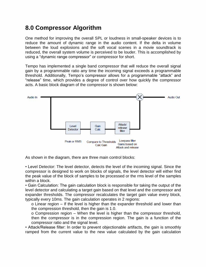
8.0 Compressor Algorithm One method for improving the overall SPL or loudness in small-speaker devices is to reduce the amount of dynamic range in the audio content. If the delta in volume between the loud explosions and the soft vocal scenes in a movie soundtrack is reduced, the overall system volume is perceived to be louder. This is accomplished by using a “dynamic range compressor” or compressor for short. Tempo has implemented a single band compressor that will reduce the overall signal gain by a programmable ratio any time the incoming signal exceeds a programmable threshold. Additionally, Tempo’s compressor allows for a programmable “attack” and “release” time, which provides a degree of control over how quickly the compressor acts. A basic block diagram of the compressor is shown below:
As shown in the diagram, there are three main control blocks: • Level Detector: The level detector, detects the level of the incoming signal. Since the compressor is designed to work on blocks of signals, the level detector will either find the peak value of the block of samples to be processed or the rms level of the samples within a block. • Gain Calculation: The gain calculation block is responsible for taking the output of the level detector and calculating a target gain based on that level and the compressor and expander thresholds. The compressor recalculates the target gain value every block, typically every 10ms. The gain calculation operates in 2 regions:
o Linear region – If the level is higher than the expander threshold and lower than the compression threshold, then the gain is 1.0. o Compression region – When the level is higher than the compressor threshold, then the compressor is in the compression region. The gain is a function of the compressor ratio and the signal level.
• Attack/Release filter: In order to prevent objectionable artifacts, the gain is smoothly ramped from the current value to the new value calculated by the gain calculation
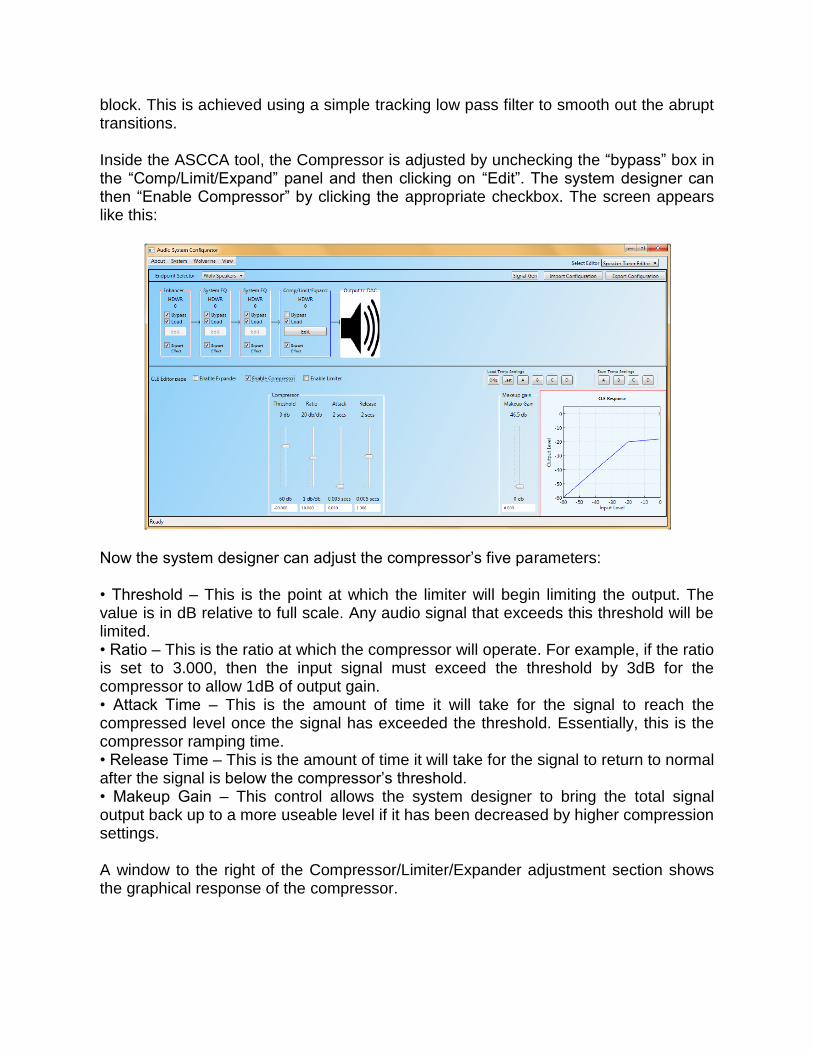
block. This is achieved using a simple tracking low pass filter to smooth out the abrupt transitions. Inside the ASCCA tool, the Compressor is adjusted by unchecking the “bypass” box in the “Comp/Limit/Expand” panel and then clicking on “Edit”. The system designer can then “Enable Compressor” by clicking the appropriate checkbox. The screen appears like this:
Now the system designer can adjust the compressor’s five parameters: • Threshold – This is the point at which the limiter will begin limiting the output. The value is in dB relative to full scale. Any audio signal that exceeds this threshold will be limited. • Ratio – This is the ratio at which the compressor will operate. For example, if the ratio is set to 3.000, then the input signal must exceed the threshold by 3dB for the compressor to allow 1dB of output gain. • Attack Time – This is the amount of time it will take for the signal to reach the compressed level once the signal has exceeded the threshold. Essentially, this is the compressor ramping time. • Release Time – This is the amount of time it will take for the signal to return to normal after the signal is below the compressor’s threshold. • Makeup Gain – This control allows the system designer to bring the total signal output back up to a more useable level if it has been decreased by higher compression settings. A window to the right of the Compressor/Limiter/Expander adjustment section shows the graphical response of the compressor.
The exact compression settings are very dependent on the system solution, speakers chosen, and audible preferences. For more information on the theory of using a compressor and some various general settings, an internet search will result in a wealth of information. One useful site is: http://www.bhphotovideo.com/find/newsLetter/Taming-Your-AudioSignal.jsp Note that Tempo’s compressor may not be capable of all features described in this document.
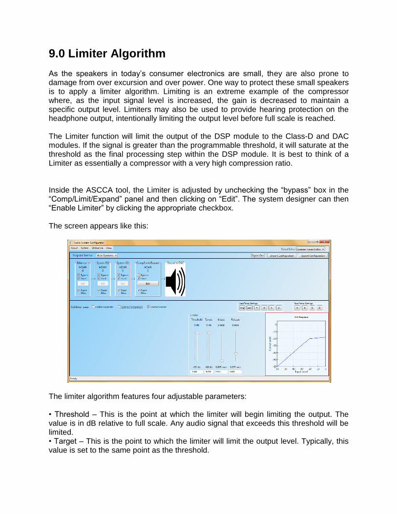
9.0 Limiter Algorithm As the speakers in today’s consumer electronics are small, they are also prone to damage from over excursion and over power. One way to protect these small speakers is to apply a limiter algorithm. Limiting is an extreme example of the compressor where, as the input signal level is increased, the gain is decreased to maintain a specific output level. Limiters may also be used to provide hearing protection on the headphone output, intentionally limiting the output level before full scale is reached. The Limiter function will limit the output of the DSP module to the Class-D and DAC modules. If the signal is greater than the programmable threshold, it will saturate at the threshold as the final processing step within the DSP module. It is best to think of a Limiter as essentially a compressor with a very high compression ratio. Inside the ASCCA tool, the Limiter is adjusted by unchecking the “bypass” box in the “Comp/Limit/Expand” panel and then clicking on “Edit”. The system designer can then “Enable Limiter” by clicking the appropriate checkbox. The screen appears like this:
The limiter algorithm features four adjustable parameters: • Threshold – This is the point at which the limiter will begin limiting the output. The value is in dB relative to full scale. Any audio signal that exceeds this threshold will be limited. • Target – This is the point to which the limiter will limit the output level. Typically, this value is set to the same point as the threshold.

• Attack Time – This is the amount of time it will take for the signal to reach the limited level once the signal has exceeded the threshold. Essentially, this is the limiter ramping time. • Release Time – This is the amount of time it will take for the signal to return to normal after the signal is below the limiter’s threshold. The exact settings for the limiter are very dependent on the system solution, speakers chosen, and audible preferences.
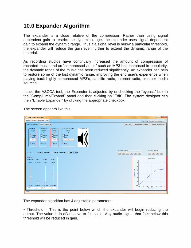
10.0 Expander Algorithm The expander is a close relative of the compressor. Rather than using signal dependent gain to restrict the dynamic range, the expander uses signal dependent gain to expand the dynamic range. Thus if a signal level is below a particular threshold, the expander will reduce the gain even further to extend the dynamic range of the material. As recording studios have continually increased the amount of compression of recorded music and as “compressed audio” such as MP3 has increased in popularity, the dynamic range of the music has been reduced significantly. An expander can help to restore some of the lost dynamic range, improving the end user’s experience when playing back highly compressed MP3’s, satellite radio, internet radio, or other media sources. Inside the ASCCA tool, the Expander is adjusted by unchecking the “bypass” box in the “Comp/Limit/Expand” panel and then clicking on “Edit”. The system designer can then “Enable Expander” by clicking the appropriate checkbox. The screen appears like this:
The expander algorithm has 4 adjustable parameters: • Threshold – This is the point below which the expander will begin reducing the output. The value is in dB relative to full scale. Any audio signal that falls below this threshold will be reduced in gain.
• Ratio – This is the ratio at which the expander will operate. For example, if the ratio is set to 3.000 and the input signal falls below the threshold by -3dB, the expander will only output -9dB. • Attack Time – This is the amount of time it will take a signal to reach the expanded level after the signal as crossed below the expander’s threshold. Essentially this is the expander’s ramping time. • Release Time – This is the amount of time it will take a signal to return to normal after the signal has crossed above the expander’s threshold.
11.0 Putting it All Together The Tempo Semiconductor ACS422xx and ACS62200 products are very versatile parts with regards to audio processing. While this document has focused on each individual feature, it is important to note that any or all of the features can be enabled simultaneously. As a system designer, you can “choose your own adventure”. However, be cautious and aware of how the processing is affecting the total output level, phase, and fidelity of the part.
12.0 Saving the Settings The ASCCA is a very versatile and powerful tool, allowing the system designer to perform real-time adjustments of the audio processing algorithms. It is important to note that the tool does provide several output formats for the system designer. Once a design is complete, or if the designer chooses to save the work in progress, he/she can click on the “Export Configuration” button in the top right of the ASCCA tool in order to save the work. The output choices are: • RPT – This is a text based report of all the settings included in the current work in progress. • DSPS – This file contains the memory dump of the current ASCCA state (EQ coefficients, enhancement parameters, etc). This file is formatted for use inside a C-code program. • COEFFS – Similar to DSPS, this file contains the memory dump of the current ASCCA state (EQ coefficients, enhancement parameters, etc). This file is formatted for use by Tempo’s “devregtest.jar” direct register access tool. • PNL – This is ASCCA’s native file format. This is the only file format that can be imported by ASCCA. This file will allow ASCCA to immediately resume where it left off. • ALL – This option will export all of the above files to the specified location. The system designer of a tablet or microcontroller device will need to format the output of ASCCA to be usable by their code and their system. DISCLAIMER Tempo Semiconductor Inc. (Tempo) and its subsidiaries reserve the right to modify the products and/or specifications described herein at any time and at Tempo’s sole discretion. All information in this document, including descriptions of product features and performance, is subject to change without notice. Performance specifications and the operating parameters of the described products are determined in the independent state and are not guaranteed to perform the same way when installed in customer products. The information contained herein is provided without representation or warranty of any kind, whether express or implied, including, but not limited to, the suitability of Tempo’s products for any particular purpose, an implied warranty of merchantability, or non-infringement of the intellectual property rights of others. This document is presented only as a guide and does not convey any license under intellectual property rights of Tempo or any third parties. Tempo’s products are not intended for use in life support systems or similar devices where the failure or malfunction of a Tempo product can be reasonably expected to significantly affect the health or safety of users. Anyone using a Tempo product in such a manner does so at their own risk, absent an express, written agreement by Tempo. Tempo Semiconductor, Tempo and the Tempo logo are registered trademarks of Tempo Semiconductor Incorporated. Other trademarks and service marks used herein, including protected names, logos and designs, are the property of Tempo or their respective third party owners. DDX™ and the DDX logo are trademarks of Apogee Technology.
Related Documents


![An audio-driven rule-based approach · 2018. 9. 10. · scenes [6] and the current Web Audio API [7] provides several real-time audio processing functions implemented in assembly/C/C++](https://static.cupdf.com/doc/110x72/60565137993539032271062d/an-audio-driven-rule-based-approach-2018-9-10-scenes-6-and-the-current-web.jpg)

