© 2010 Microchip Technology Inc. DS70297B Audio PICtail™ Plus Daughter Board User’s Guide

Welcome message from author
This document is posted to help you gain knowledge. Please leave a comment to let me know what you think about it! Share it to your friends and learn new things together.
Transcript
© 2010 Microchip Technology Inc. DS70297B
Audio PICtail™ Plus Daughter
Board User’s Guide
Information contained in this publication regarding deviceapplications and the like is provided only for your convenienceand may be superseded by updates. It is your responsibility toensure that your application meets with your specifications.MICROCHIP MAKES NO REPRESENTATIONS ORWARRANTIES OF ANY KIND WHETHER EXPRESS ORIMPLIED, WRITTEN OR ORAL, STATUTORY OROTHERWISE, RELATED TO THE INFORMATION,INCLUDING BUT NOT LIMITED TO ITS CONDITION,QUALITY, PERFORMANCE, MERCHANTABILITY ORFITNESS FOR PURPOSE. Microchip disclaims all liabilityarising from this information and its use. Use of Microchipdevices in life support and/or safety applications is entirely atthe buyer’s risk, and the buyer agrees to defend, indemnify andhold harmless Microchip from any and all damages, claims,suits, or expenses resulting from such use. No licenses areconveyed, implicitly or otherwise, under any Microchipintellectual property rights.
DS70297B-page 2
Trademarks
The Microchip name and logo, the Microchip logo, dsPIC, KEELOQ, KEELOQ logo, MPLAB, PIC, PICmicro, PICSTART, PIC32 logo, rfPIC and UNI/O are registered trademarks of Microchip Technology Incorporated in the U.S.A. and other countries.
FilterLab, Hampshire, HI-TECH C, Linear Active Thermistor, MXDEV, MXLAB, SEEVAL and The Embedded Control Solutions Company are registered trademarks of Microchip Technology Incorporated in the U.S.A.
Analog-for-the-Digital Age, Application Maestro, CodeGuard, dsPICDEM, dsPICDEM.net, dsPICworks, dsSPEAK, ECAN, ECONOMONITOR, FanSense, HI-TIDE, In-Circuit Serial Programming, ICSP, Mindi, MiWi, MPASM, MPLAB Certified logo, MPLIB, MPLINK, mTouch, Octopus, Omniscient Code Generation, PICC, PICC-18, PICDEM, PICDEM.net, PICkit, PICtail, REAL ICE, rfLAB, Select Mode, Total Endurance, TSHARC, UniWinDriver, WiperLock and ZENA are trademarks of Microchip Technology Incorporated in the U.S.A. and other countries.
SQTP is a service mark of Microchip Technology Incorporated in the U.S.A.
All other trademarks mentioned herein are property of their respective companies.
© 2010, Microchip Technology Incorporated, Printed in the U.S.A., All Rights Reserved.
Printed on recycled paper.
ISBN: 978-1-60932-046-1Microchip received ISO/TS-16949:2002 certification for its worldwide
Note the following details of the code protection feature on Microchip devices:• Microchip products meet the specification contained in their particular Microchip Data Sheet.
• Microchip believes that its family of products is one of the most secure families of its kind on the market today, when used in the intended manner and under normal conditions.
• There are dishonest and possibly illegal methods used to breach the code protection feature. All of these methods, to our knowledge, require using the Microchip products in a manner outside the operating specifications contained in Microchip’s Data Sheets. Most likely, the person doing so is engaged in theft of intellectual property.
• Microchip is willing to work with the customer who is concerned about the integrity of their code.
• Neither Microchip nor any other semiconductor manufacturer can guarantee the security of their code. Code protection does not mean that we are guaranteeing the product as “unbreakable.”
Code protection is constantly evolving. We at Microchip are committed to continuously improving the code protection features of ourproducts. Attempts to break Microchip’s code protection feature may be a violation of the Digital Millennium Copyright Act. If such actsallow unauthorized access to your software or other copyrighted work, you may have a right to sue for relief under that Act.
headquarters, design and wafer fabrication facilities in Chandler and Tempe, Arizona; Gresham, Oregon and design centers in California and India. The Company’s quality system processes and procedures are for its PIC® MCUs and dsPIC® DSCs, KEELOQ® code hopping devices, Serial EEPROMs, microperipherals, nonvolatile memory and analog products. In addition, Microchip’s quality system for the design and manufacture of development systems is ISO 9001:2000 certified.
© 2010 Microchip Technology Inc.
AUDIO PICtail™ PLUS DAUGHTER
BOARD USER’S GUIDETable of Contents
Preface ........................................................................................................................... 5Chapter 1. Introduction
1.1 Overview ...................................................................................................... 111.2 Board Setup ................................................................................................. 121.3 Reference Documents .................................................................................. 12
Chapter 2. Hardware2.1 Functional Overview ..................................................................................... 132.2 Hardware Components ................................................................................ 15
Chapter 3. PWM Speech Loopback Demo3.1 Speech Loopback Demo .............................................................................. 213.2 Running the Demo ....................................................................................... 24
Appendix A. Drawings and SchematicsA.1 Audio PICtail Plus Daughter Board Layout .................................................. 25A.2 Schematic Diagrams .................................................................................... 26
Index ............................................................................................................................. 31Worldwide Sales and Service .................................................................................... 32
© 2010 Microchip Technology Inc. DS70297B-page 3
Audio PICtail™ Plus Daughter Board User’s Guide
NOTES:
DS70297B-page 4 © 2010 Microchip Technology Inc.

AUDIO PICtail™ PLUS DAUGHTERBOARD USER’S GUIDE
Preface
© 2010 Microchip Tech
INTRODUCTION
NOTICE TO CUSTOMERS
All documentation becomes dated, and this manual is no exception. Microchip tools and documentation are constantly evolving to meet customer needs, so some actual dialogs and/or tool descriptions may differ from those in this document. Please refer to our web site (www.microchip.com) to obtain the latest documentation available.
Documents are identified with a “DS” number. This number is located on the bottom of each page, in front of the page number. The numbering convention for the DS number is “DSXXXXXA”, where “XXXXX” is the document number and “A” is the revision level of the document.
For the most up-to-date information on development tools, see the MPLAB® IDE on-line help. Select the Help menu, and then Topics to open a list of available on-line help files.
This chapter contains general information that will be useful to know before using the Audio PICtail™ Plus Daughter Board. Items discussed in this chapter include:• Document Layout• Conventions Used in this Guide• Warranty Registration• Recommended Reading• The Microchip Web Site• Development Systems Customer Change Notification Service• Customer Support• Document Revision History
DOCUMENT LAYOUT
This user’s guide describes how to use the Audio PICtail Plus Daughter Board as a development tool to emulate and debug firmware on a target board. The manual layout is as follows: • Chapter 1. “Introduction” – This chapter introduces the Audio PICtail PlusDaughter Board and provides an overview of its features.• Chapter 2. “Hardware” – This chapter provides a functional overview of the
Audio PICtail Plus Daughter Board and identifies the major hardware components.
• Chapter 3. “PWM Speech Loopback Demo” – This chapter describes a simple loopback program that demonstrates how to use the Audio PICtail Plus Daughter Board for speech capture and playback without the use of a codec.
• Appendix A. “Drawings and Schematics” – This appendix provides detailed technical drawings and schematic diagrams of the Audio PICtail Plus Daughter Board.
nology Inc. DS70297B-page 5
Audio PICtail™ Plus Daughter Board User’s Guide
CONVENTIONS USED IN THIS GUIDE
DS70297B-page 6
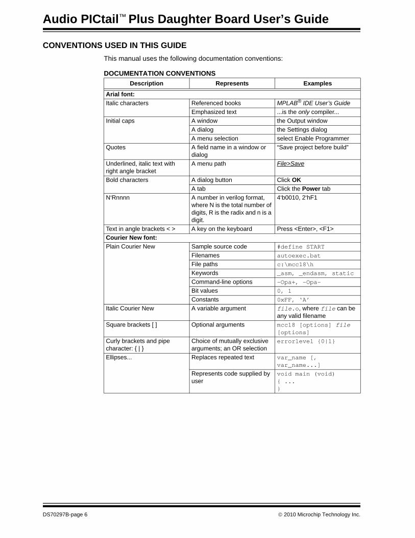
This manual uses the following documentation conventions:
DOCUMENTATION CONVENTIONSDescription Represents Examples
Arial font:Italic characters Referenced books MPLAB® IDE User’s Guide
Emphasized text ...is the only compiler...Initial caps A window the Output window
A dialog the Settings dialogA menu selection select Enable Programmer
Quotes A field name in a window or dialog
“Save project before build”
Underlined, italic text with right angle bracket
A menu path File>Save
Bold characters A dialog button Click OKA tab Click the Power tab
N‘Rnnnn A number in verilog format, where N is the total number of digits, R is the radix and n is a digit.
4‘b0010, 2‘hF1
Text in angle brackets < > A key on the keyboard Press <Enter>, <F1>Courier New font:Plain Courier New Sample source code #define START
Filenames autoexec.batFile paths c:\mcc18\h
Keywords _asm, _endasm, static
Command-line options -Opa+, -Opa-Bit values 0, 1
Constants 0xFF, ‘A’
Italic Courier New A variable argument file.o, where file can be any valid filename
Square brackets [ ] Optional arguments mcc18 [options] file [options]
Curly brackets and pipe character: { | }
Choice of mutually exclusive arguments; an OR selection
errorlevel {0|1}
Ellipses... Replaces repeated text var_name [, var_name...]
Represents code supplied by user
void main (void){ ...}
© 2010 Microchip Technology Inc.
Preface
WARRANTY REGISTRATION
© 2010 Microchip Tech
Please complete the enclosed Warranty Registration Card and mail it promptly. Sending in the Warranty Registration Card entitles users to receive new product updates. Interim software releases are available at the Microchip web site.
RECOMMENDED READING
This user's guide describes how to use the Audio PICtail Plus Daughter Board. Other useful documents are listed below. The following Microchip documents are available and recommended as supplemental reference resources.Readme FilesFor the latest information on using other tools, read the tool-specific Readme files in the Readmes subdirectory of the MPLAB IDE installation directory. The Readme files contain update information and known issues that may not be included in this user’s guide.dsPIC33F/PIC24H Family Reference Manual SectionsRefer these documents for detailed information on dsPIC33F/PIC24H device operation. These reference manual sections explain the operation of the dsPIC33F/PIC24H DSC and MCU family architecture and peripheral modules, but do not cover the specifics of each device. Refer to the appropriate device data sheet for the device-specific information.dsPIC33FJXXXGPX06/X08/X10 Data Sheet (DS70286)This document provides an overview of the functionality of the dsPIC33F DSC product family. It includes device-specific information such as pinout diagrams, register maps, electrical specifications and packaging, in addition to an overview of the CPU and peripheral features.16-bit MCU and DSC Programmer’s Reference Manual (DS70157)This manual is a software developer’s reference for the 16-bit PIC24F and PIC24H MCU, and 16-bit dsPIC30F and dsPIC33F DSC families of devices. It describes the instruction set in detail and also provides general information to assist in developing software for these device families.MPLAB® Assembler, Linker and Utilities for PIC24 MCUs and dsPIC® DSCs User’s Guide (DS51317)This document details Microchip Technology’s language tools for dsPIC® DSC devices based on GNU technology. The language tools discussed are:• MPLAB Assembler PIC24 MCUs and dsPIC® DSCs• MPLAB Linker PIC24 MCUs and dsPIC® DSCs• MPLAB Archiver/Librarian PIC24 MCUs and dsPIC® DSCs• Other UtilitiesMPLAB® C Compiler for PIC24 MCUs and dsPIC® DSCs User’s Guide (DS51284)This document details the use of Microchip’s MPLAB C Compiler for dsPIC DSC devices to develop an application. The MPLAB C Compiler is a GNU-based language tool, based on source code from the Free Software Foundation (FSF). For more information about the FSF, see www.fsf.org.MPLAB® REAL ICE™ In-Circuit Emulator User’s Guide (DS51616)This document describes how to use the MPLAB REAL ICE in-circuit emulator as a development tool to emulate and debug firmware on a target board, as well as how to program devices.nology Inc. DS70297B-page 7
Audio PICtail™ Plus Daughter Board User’s Guide
THE MICROCHIP WEB SITE
DS70297B-page 8
Microchip provides online support via our web site at www.microchip.com. This web site is used as a means to make files and information easily available to customers. Accessible by using your favorite Internet browser, the web site contains the following information:• Product Support – Data sheets and errata, application notes and sample
programs, design resources, user’s guides and hardware support documents, latest software releases and archived software
• General Technical Support – Frequently Asked Questions (FAQs), technical support requests, online discussion groups, Microchip consultant program member listing
• Business of Microchip – Product selector and ordering guides, latest Microchip press releases, listing of seminars and events, listings of Microchip sales offices, distributors and factory representatives
DEVELOPMENT SYSTEMS CUSTOMER CHANGE NOTIFICATION SERVICE
Microchip’s customer notification service helps keep customers current on Microchip products. Subscribers will receive e-mail notification whenever there are changes, updates, revisions or errata related to a specified product family or development tool of interest.To register, access the Microchip web site at www.microchip.com, click on Customer Change Notification and follow the registration instructions.The Development Systems product group categories are:• Compilers – The latest information on Microchip C compilers and other languagetools. These include the MPLAB C compiler; MPASM™ and MPLAB 16-bit assemblers; MPLINK™ and MPLAB 16-bit object linkers; and MPLIB™ and MPLAB 16-bit object librarians.
• Emulators – The latest information on Microchip in-circuit emulators.This includes the MPLAB ICE 2000, MPLAB ICE 4000, MPLAB REAL ICE.
• In-Circuit Debuggers – The latest information on the Microchip in-circuit debugger, MPLAB ICD 2 and MPLAB ICD 3.
• MPLAB® IDE – The latest information on Microchip MPLAB IDE, the Windows® Integrated Development Environment for development systems tools. This list is focused on the MPLAB IDE, MPLAB SIM simulator, MPLAB IDE Project Manager and general editing and debugging features.
• Programmers – The latest information on Microchip programmers. These include the MPLAB PM3 and PRO MATE® II device programmers and the PICSTART® Plus and PICkit™ 1, 2 and 3 development programmers.
CUSTOMER SUPPORT
Users of Microchip products can receive assistance through several channels:• Distributor or Representative• Local Sales Office• Field Application Engineer (FAE)• Technical SupportCustomers should contact their distributor, representative or FAE for support. Local sales offices are also available to help customers. A listing of sales offices and locations is included in the back of this document.Technical support is available through our web site at: http://support.microchip.com© 2010 Microchip Technology Inc.
Preface
DOCUMENT REVISION HISTORY
© 2010 Microchip Tech
Revision A (October 2007)• Initial Release of this document.
Revision B (March 2010)This revision incorporates the following updates:• Appendix:
- Corrected the label “10K” as “1K” in Figure A-4.- Removed Resistor R4 of value 10K in Figure A-4.- Corrected the label “MIC_SIG” as “MIC_SIG_PRE” in Figure A-5.- Corrected the label “AT25F4096” as “SST25VF040B” in Figure A-6.
• Figure:- Updated Figure 2-1 with the input to codec does not use anti-aliasing filter.
• Section:- Removed references to AT Flash, Atmel Corporation Data Sheet,
“AT25F4096 4 Mb High Speed SPI Serial Flash Memory” (24546–SFLSH–05/06) in Section 1.3 “Reference Documents” and replaced it with reference to ST, Silicon Storage Technology, Inc. Data Sheet, “SST25VF040B 4 Mb SPI Serial Flash” (S71295–01–000)”.
• Additional minor corrections such as language and formatting updates are incorporated throughout the document.
nology Inc. DS70297B-page 9

Audio PICtail™ Plus Daughter Board User’s Guide
NOTES:
DS70297B-page 10 © 2010 Microchip Technology Inc.
AUDIO PICtail™ PLUS DAUGHTERBOARD USER’S GUIDE
Chapter 1. Introduction
© 2010 Microchip Tech
Thank you for purchasing Microchip Technology’s Audio PICtail Plus Daughter Board. This board provides a low-cost interface for speech sampling and playback. The Audio PICtail Plus Daughter Board is used with the Explorer 16 Development Board to demonstrate an effective software technique for processing acceptable voice quality audio without the use of a codec device. This chapter introduces the Audio PICtail Plus Daughter Board and provides an overview of its features. Topics covered include:• Overview• Board Setup• Reference Documents
1.1 OVERVIEW
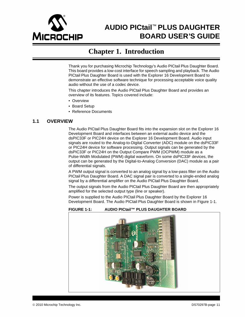
The Audio PICtail Plus Daughter Board fits into the expansion slot on the Explorer 16 Development Board and interfaces between an external audio device and the dsPIC33F or PIC24H device on the Explorer 16 Development Board. Audio input signals are routed to the Analog-to-Digital Converter (ADC) module on the dsPIC33F or PIC24H device for software processing. Output signals can be generated by the dsPIC33F or PIC24H on the Output Compare PWM (OCPWM) module as a Pulse-Width Modulated (PWM) digital waveform. On some dsPIC33F devices, the output can be generated by the Digital-to-Analog Conversion (DAC) module as a pair of differential signals.A PWM output signal is converted to an analog signal by a low-pass filter on the Audio PICtail Plus Daughter Board. A DAC signal pair is converted to a single-ended analog signal by a differential amplifier on the Audio PICtail Plus Daughter Board. The output signals from the Audio PICtail Plus Daughter Board are then appropriately amplified for the selected output type (line or speaker).Power is supplied to the Audio PICtail Plus Daughter Board by the Explorer 16 Development Board. The Audio PICtail Plus Daughter Board is shown in Figure 1-1.FIGURE 1-1: AUDIO PICtail™ PLUS DAUGHTER BOARD
nology Inc. DS70297B-page 11
Audio PICtail™ Plus Daughter Board User’s Guide
1.2 BOARD SETUP
DS70297B-page 12
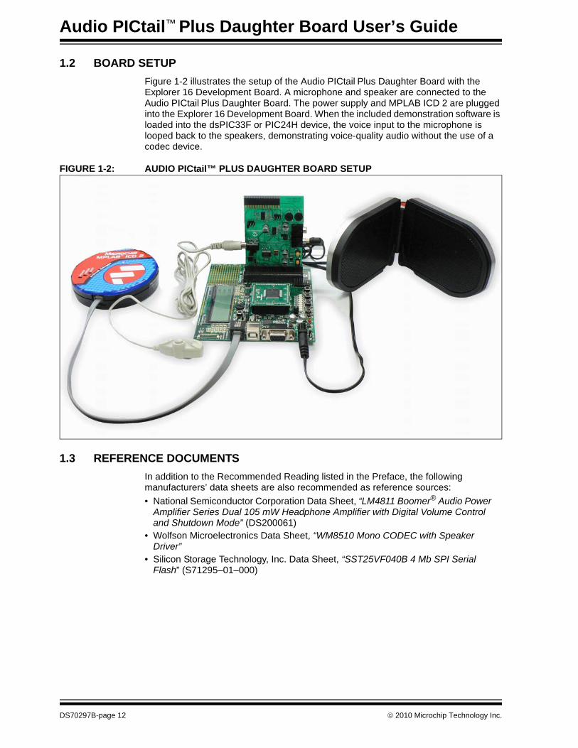
Figure 1-2 illustrates the setup of the Audio PICtail Plus Daughter Board with the Explorer 16 Development Board. A microphone and speaker are connected to the Audio PICtail Plus Daughter Board. The power supply and MPLAB ICD 2 are plugged into the Explorer 16 Development Board. When the included demonstration software is loaded into the dsPIC33F or PIC24H device, the voice input to the microphone is looped back to the speakers, demonstrating voice-quality audio without the use of a codec device.
FIGURE 1-2: AUDIO PICtail™ PLUS DAUGHTER BOARD SETUP
1.3 REFERENCE DOCUMENTS
In addition to the Recommended Reading listed in the Preface, the following manufacturers’ data sheets are also recommended as reference sources:• National Semiconductor Corporation Data Sheet, “LM4811 Boomer® Audio PowerAmplifier Series Dual 105 mW Headphone Amplifier with Digital Volume Control and Shutdown Mode” (DS200061)
• Wolfson Microelectronics Data Sheet, “WM8510 Mono CODEC with Speaker Driver”
• Silicon Storage Technology, Inc. Data Sheet, “SST25VF040B 4 Mb SPI Serial Flash” (S71295–01–000)
© 2010 Microchip Technology Inc.
AUDIO PICtail™ PLUS DAUGHTERBOARD USER’S GUIDE
Chapter 2. Hardware
© 2010 Microchip Tech
This chapter provides a functional overview of the Audio PICtail Plus Daughter Board and identifies the major hardware components. Topics covered include:• Functional Overview• Hardware Components
2.1 FUNCTIONAL OVERVIEW
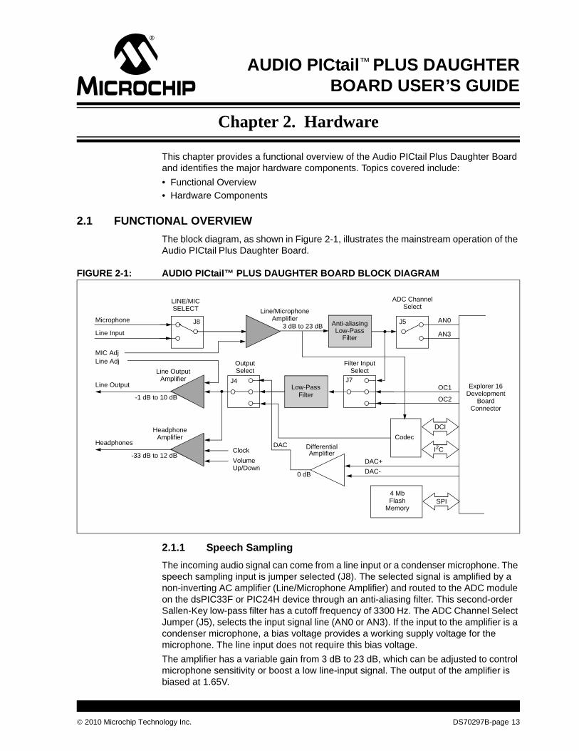
The block diagram, as shown in Figure 2-1, illustrates the mainstream operation of the Audio PICtail Plus Daughter Board.FIGURE 2-1: AUDIO PICtail™ PLUS DAUGHTER BOARD BLOCK DIAGRAM
Explorer 16Development
Board
AN0
AN3
OC1
OC2
Microphone
Line Input
Low-PassFilter
Line Output
Headphones
Line OutputAmplifier
HeadphoneAmplifier
-1 dB to 10 dB
LINE/MICSELECT
ADC ChannelSelect
Filter InputSelect
Line/MicrophoneAmplifier
SPI4 MbFlash
Memory
Clock Volume
CodecDCI
I2C
DAC+DAC-
DAC DifferentialAmplifier
MIC AdjLine Adj Output
Select
Connector
J8
J4 J7
J53 dB to 23 dB
0 dB
-33 dB to 12 dB
Anti-aliasing
FilterLow-Pass
Up/Down
2.1.1 Speech SamplingThe incoming audio signal can come from a line input or a condenser microphone. The speech sampling input is jumper selected (J8). The selected signal is amplified by a non-inverting AC amplifier (Line/Microphone Amplifier) and routed to the ADC module on the dsPIC33F or PIC24H device through an anti-aliasing filter. This second-order Sallen-Key low-pass filter has a cutoff frequency of 3300 Hz. The ADC Channel Select Jumper (J5), selects the input signal line (AN0 or AN3). If the input to the amplifier is a condenser microphone, a bias voltage provides a working supply voltage for the microphone. The line input does not require this bias voltage.The amplifier has a variable gain from 3 dB to 23 dB, which can be adjusted to control microphone sensitivity or boost a low line-input signal. The output of the amplifier is biased at 1.65V.
nology Inc. DS70297B-page 13
Audio PICtail™ Plus Daughter Board User’s Guide
DS70297B-page 14
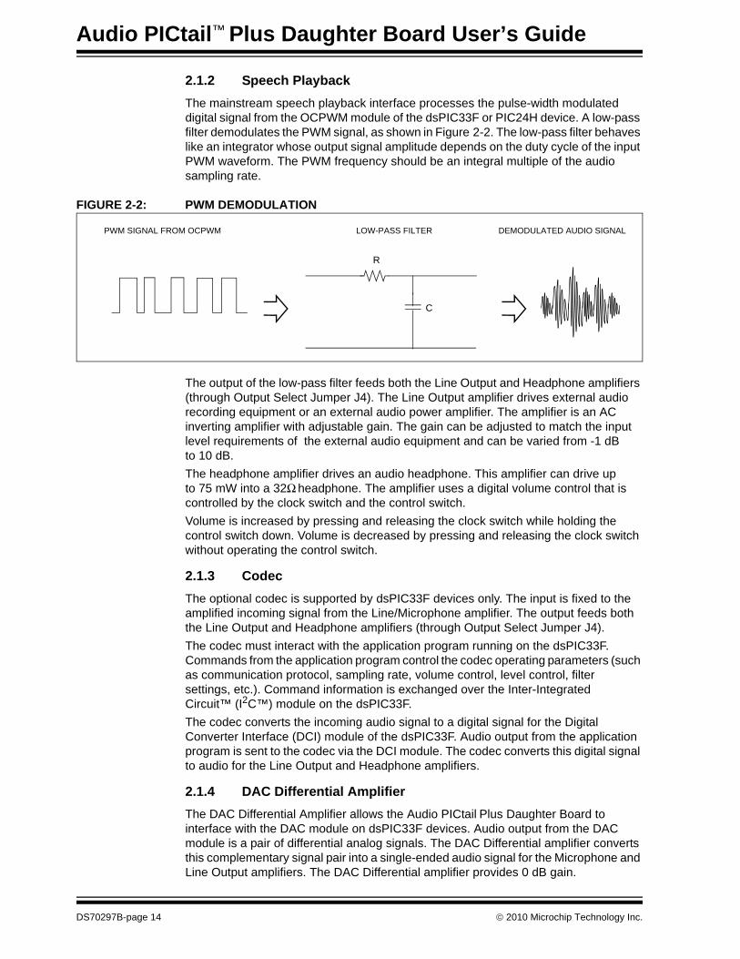
2.1.2 Speech PlaybackThe mainstream speech playback interface processes the pulse-width modulated digital signal from the OCPWM module of the dsPIC33F or PIC24H device. A low-pass filter demodulates the PWM signal, as shown in Figure 2-2. The low-pass filter behaves like an integrator whose output signal amplitude depends on the duty cycle of the input PWM waveform. The PWM frequency should be an integral multiple of the audio sampling rate.
FIGURE 2-2: PWM DEMODULATION
C
R
PWM SIGNAL FROM OCPWM LOW-PASS FILTER DEMODULATED AUDIO SIGNAL
The output of the low-pass filter feeds both the Line Output and Headphone amplifiers (through Output Select Jumper J4). The Line Output amplifier drives external audio recording equipment or an external audio power amplifier. The amplifier is an AC inverting amplifier with adjustable gain. The gain can be adjusted to match the input level requirements of the external audio equipment and can be varied from -1 dB to 10 dB.The headphone amplifier drives an audio headphone. This amplifier can drive up to 75 mW into a 32Ω headphone. The amplifier uses a digital volume control that is controlled by the clock switch and the control switch.Volume is increased by pressing and releasing the clock switch while holding the control switch down. Volume is decreased by pressing and releasing the clock switch without operating the control switch.
2.1.3 CodecThe optional codec is supported by dsPIC33F devices only. The input is fixed to the amplified incoming signal from the Line/Microphone amplifier. The output feeds both the Line Output and Headphone amplifiers (through Output Select Jumper J4). The codec must interact with the application program running on the dsPIC33F. Commands from the application program control the codec operating parameters (such as communication protocol, sampling rate, volume control, level control, filter settings, etc.). Command information is exchanged over the Inter-Integrated Circuit™ (I2C™) module on the dsPIC33F.The codec converts the incoming audio signal to a digital signal for the Digital Converter Interface (DCI) module of the dsPIC33F. Audio output from the application program is sent to the codec via the DCI module. The codec converts this digital signal to audio for the Line Output and Headphone amplifiers.
2.1.4 DAC Differential AmplifierThe DAC Differential Amplifier allows the Audio PICtail Plus Daughter Board to interface with the DAC module on dsPIC33F devices. Audio output from the DAC module is a pair of differential analog signals. The DAC Differential amplifier converts this complementary signal pair into a single-ended audio signal for the Microphone and Line Output amplifiers. The DAC Differential amplifier provides 0 dB gain.
© 2010 Microchip Technology Inc.
Hardware
© 2010 Microchip Tech
2.1.5 4 Mb Serial Flash MemoryThe Audio PICtail Plus Daughter Board includes 4 Mb serial Flash memory that can be used for storing data. The memory interfaces with the SPI bus on dsPIC33F and PIC24H devices and might typically be used by applications that require storage of speech samples for playback purposes.
2.2 HARDWARE COMPONENTS
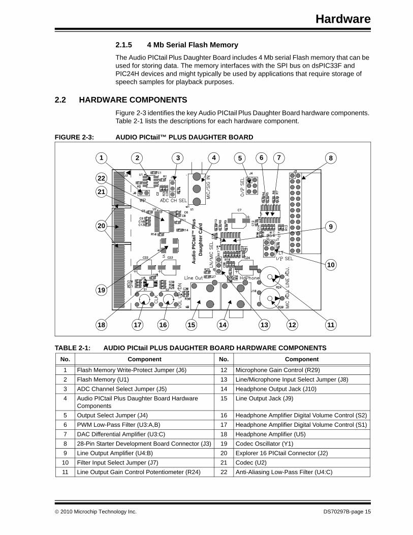
Figure 2-3 identifies the key Audio PICtail Plus Daughter Board hardware components. Table 2-1 lists the descriptions for each hardware component.FIGURE 2-3: AUDIO PICtail™ PLUS DAUGHTER BOARD
TABLE 2-1: AUDIO PICtail PLUS DAUGHTER BOARD HARDWARE COMPONENTSNo. Component No. Component
1 Flash Memory Write-Protect Jumper (J6) 12 Microphone Gain Control (R29)2 Flash Memory (U1) 13 Line/Microphone Input Select Jumper (J8)3 ADC Channel Select Jumper (J5) 14 Headphone Output Jack (J10)4 Audio PICtail Plus Daughter Board Hardware
Components15 Line Output Jack (J9)
5 Output Select Jumper (J4) 16 Headphone Amplifier Digital Volume Control (S2)6 PWM Low-Pass Filter (U3:A,B) 17 Headphone Amplifier Digital Volume Control (S1)7 DAC Differential Amplifier (U3:C) 18 Headphone Amplifier (U5)8 28-Pin Starter Development Board Connector (J3) 19 Codec Oscillator (Y1)9 Line Output Amplifier (U4:B) 20 Explorer 16 PICtail Connector (J2)10 Filter Input Select Jumper (J7) 21 Codec (U2)11 Line Output Gain Control Potentiometer (R24) 22 Anti-Aliasing Low-Pass Filter (U4:C)
1 2 3 4 5 7 8
9
10
1112131415161718
19
20
21
6
22
Aud
io P
ICta
il™ P
lus
Dau
ghte
r Car
d
nology Inc.
DS70297B-page 15
Audio PICtail™ Plus Daughter Board User’s Guide
DS70297B-page 16
2.2.1 Line/Microphone Input Phone Jack (J1)The Line/Microphone Input (No. 4) is a 3.5 mm mono input phone jack (MJ3502). This connection accepts either a condenser microphone or a line level signal, as shown in the schematic in Figure A-2.
Note: The microphone or the line level signal should be connected to J1 using a mono 3.5 mm connector.
2.2.2 Line/Microphone Input Select Jumper (J8)The Line/Microphone Input Select Jumper (No. 13) determines if the Microphone/Line Pre-Amplifier (U4:A) operates as a line amplifier or a microphone amplifier. If the MIC option is selected, a bias voltage of +5V is applied to the Line/Microphone Input Phone Jack (J1), as shown in the schematic in Figure A-2.
2.2.3 Line/Microphone Pre-Amplifier (U4:A)The Line/Microphone Pre-Amplifier (No. 9) is implemented using one of the four op amps on the MCP6024 quad op amp IC (U4). The output of this non-inverting AC amplifier is biased at 1.65V. The gain of the amplifier is controlled by potentiometer R29, as shown by Equation 2-1.
EQUATION 2-1: INPUT PRE-AMPLIFIER GAIN
See Figure A-2 for the complete schematic of the Line/Microphone Pre-Amplifier.
2.2.4 Anti-Aliasing Low-Pass Filter (U4:C)The Anti-Aliasing Low-Pass Filter uses one of the four operational amplifiers on the MCP6024 quad op amp IC (U4). The output of the Line/Microphone Pre-Amplifier (No. 22) uses an anti-aliasing low-pass second-order Sallen-Key structure to filter the signal and provide a cut-off frequency of 3300 Hz.See Figure A-3 for a schematic of the Anti-Aliasing Low-Pass Filter.
2.2.5 Microphone Gain Control (R29)MIC ADJ Potentiometer R29 (No. 12) controls the gain of the Line/Microphone Pre-Amplifier (U4:A).
Gain 1 R29 R17+( )R3
-------------------------------⎝ ⎠⎛ ⎞+=
Note: Setting the gain too high can cause the output of the amplifier to saturate and clip.
See Figure A-2 for the complete schematic of the Line/Microphone Pre-Amplifier.
2.2.6 ADC Channel Select Jumper (J5)The ADC Channel Select Jumper (No. 3) is used to select the analog-to-digital input channel (AN0 or AN3) on the dsPIC33F or PIC24H device on the Explorer 16 Development Board.To use channel AN0, place the jumper between pins 2 and 3 on the ADC CH SEL header, as shown in Figure A-2. To use channel AN3, place the jumper between pins 1 and 2.
© 2010 Microchip Technology Inc.

Hardware
© 2010 Microchip Tech
2.2.7 PWM Low-Pass Filter (U3:A,B)The PWM signal from the OCPWM module on the dsPIC33F or PIC24H device on the Explorer 16 Development Board is demodulated by the PWM low-pass filter (No. 6). This fourth order filter uses two of the four op amps (U3:A and U3:B) on the MCP6024 quad op amp IC. The PWM signal from the OCPWM module on the dsPIC33F or PIC24H device on the Explorer 16 Development Board is demodulated by the PWM low-pass filter (No. 6). This fourth order filter uses two of the four op amps (U3:A and U3:B) on the MCP6024 quad op amp IC.The input to the filter is selected by the Filter Input Select Jumper (J7). The output of the filter is routed to the headphone and line output amplifiers via the Output Select Jumper (J4).The complete schematic of the low-pass filter, the input select jumper and the output select jumper is shown in Figure A-4.
2.2.8 Filter Input Select Jumper (J7)The input to the PWM Low-Pass Filter is selected by the FLT I/P SEL Jumper (No. 10). This jumper allows the following inputs to be selected:• OCPWM channel 1 output (OC1) of the dsPIC33F or PIC24H device on the
Explorer 16 Development Board• OCPWM channel 2 output (OC2) of the dsPIC33F or PIC24H device on the
Explorer 16 Development Board• Output of the Line/Microphone Pre-Amplifier (MIC_SIG)
2.2.9 Output Select Jumper (J4)The Output Select Jumper (No. 5) determines whether the input signal for the Line Output and Headphone Amplifiers comes from the PWM Filter, the codec or the differential amplifier that converts a digital audio signal from the dsPIC33F device.See Figure A-4 for circuit details.
2.2.10 Line Output Amplifier (U4:B)The Line Output Amplifier is implemented using one of the four op amps on the MCP6024 quad op amp IC (No. 9). The output of this inverting AC amplifier is intended to drive an external audio amplifier or recording device. The signal is AC-coupled to the Line Output Jack (J9). The gain of the amplifier is controlled by the Line Adjust Potentiometer (R24), as shown by Equation 2-2.
EQUATION 2-2: LINE OUTPUT AMPLIFIER GAIN
See Figure A-4 for a complete schematic of the Line Output Amplifier.
Gain R24 R19+( )R21
-------------------------------=
nology Inc. DS70297B-page 17
Audio PICtail™ Plus Daughter Board User’s Guide
DS70297B-page 18
2.2.11 Line Output Gain Control Potentiometer (R24)LINE ADJ potentiometer R24 (No. 11) controls the gain of the Line Output Amplifier (U4:B).
Note: Setting the gain too high can cause the output of the amplifier to saturate and clip.
See Figure A-4 for a complete schematic of the Line Output Amplifier.
2.2.12 Line Output Jack (J9)Line out jack J9 (No. 15) is a 3.5 mm stereo socket that can be used to connect the output of the line output amplifier to an external power amplifier or recording equipment. See Figure A-4 for a complete schematic of the Line Output Amplifier.
2.2.13 Headphone Amplifier (U5)The Headphone Amplifier (No. 18) is a National Semiconductor LM4811 70 mW stereo amplifier with digital volume control. The input to the amplifier is controlled by the setting of Output Select Jumper (J4). The output of the amplifier is available at Headphone Output Jack (J10). Gain is controlled by the voltage levels applied through the CLK switch (S1) and VOL UP/DN switch (S2). Each time the CLK switch is pressed, the gain increases or decreases by 3 dB, depending on the status of the VOL UP/DN switch. If both switches are pressed, the gain increases on the leading edge of the CLK signal. If only the CLK switch is pressed, the gain decreases on the leading edge of the CLK signal. The gain can be adjusted over a range of +12 dB to -33 dB in 16 discrete gain settings.See Figure A-4 for a complete schematic of the Headphone Amplifier.
2.2.14 Headphone Amplifier Digital Volume ControlVolume is increased by pressing and releasing the CLK switch (No. 17) while holding down the VOL UP/DN switch (No. 16). Volume is decreased by pressing and releasing the CLK switch without operating the VOL UP/DN switch.See Figure A-4 for a complete schematic of the Headphone Amplifier.
2.2.15 Headphone Output Jack (J10)The Headphone Jack (No. 14) is a 3.5 mm stereo connector. A 32Ω headphone can be connected to this socket.See Figure A-4 for a complete schematic of the Headphone Amplifier.
2.2.16 DAC Differential Amplifier (U3:C)The DAC Differential Amplifier (No. 7) allows the Audio PICtail Plus Daughter Board to interface with the DAC module on dsPIC33F devices. Audio output from the DAC module is a pair of buffered differential analog signals. The DAC Differential amplifier converts this complementary signal pair into a single-ended audio signal for the Microphone and Line Output amplifiers. This amplifier uses one of the four op amps (U3:C) on the MCP6024 quad op amp IC (No. 7). The DAC Differential Amplifier provides 0 dB gain.See Figure A-4 for a complete schematic of the DAC Differential Amplifier.
© 2010 Microchip Technology Inc.

Hardware
© 2010 Microchip Tech
2.2.17 Codec (U2)The Audio PICtail Plus Daughter Board includes an optional codec (No. 21) that interfaces to the DCI module (data interface) and I2C bus (control interface) of the dsPIC33F device on the Explorer 16 Development Board. It is also AC coupled to the output of the Line/Microphone Amplifier (MIC_SIG).The codec is a Wolfson WM8510 and uses oscillator Y1 for clocking. See Figure A-5 for a complete schematic of the Codec.
2.2.18 Codec Oscillator (Y1)Codec Oscillator Y1 (No. 19) provides a required 12 MHz master clock signal to the 16-bit Codec (U2). See Figure A-5 for a complete schematic of the Codec.
2.2.19 Flash Memory (U1)The Audio PICtail Plus Daughter Board includes a serial Flash memory chip (No. 2). This memory is write protected when the jumper pin is inserted in WP (Jumper J6).See Figure A-6 for a complete schematic of the Flash memory circuit.
2.2.20 Flash Memory Write-Protect Jumper (J6)When the jumper pin is inserted in WP (No. 1), write operations to the serial Flash memory have no effect.
2.2.21 Explorer 16 PICtail Connector (J2)The Audio PICtail Plus Daughter Board connects to the Explorer 16 Development Board using edge connector J3 (No. 20). The Audio PICtail Plus Daughter Board uses these Explorer 16 signals:• +3.3V power• +5V power• Ground• dsPIC33F device DCI module signals• dsPIC33F or PIC24H Output Compare module signals• dsPIC33F or PIC24H SPI2 module signals• dsPIC33For PIC24H I2C2 module signals• dsPIC33F or PIC24H ADC module inputs
2.2.22 28-Pin Starter Development Board Connector (J3)The 28-Pin Starter Development Board Connector (No. 8) allows the Audio PICtail Plus Daughter Board to be connected to Microchip's 28-Pin Starter Development Board.
CAUTION
To avoid damage to the Audio PICtail Plus Daughter Board, the 28-Pin Starter Development Board must operate at +3.3V when it is connected to the Audio PICtail
Plus Daughter Board.
nology Inc. DS70297B-page 19

Audio PICtail™ Plus Daughter Board User’s Guide
NOTES:
DS70297B-page 20 © 2010 Microchip Technology Inc.
AUDIO PICtail™ PLUS DAUGHTERBOARD USER’S GUIDE
Chapter 3. PWM Speech Loopback Demo
© 2010 Microchip Tech
This chapter describes a simple program that demonstrates how to use the Audio PICtail Plus Daughter Board for speech capture and loopback without the use of a codec. Topics covered include:• Speech Loopback Demo• Running the Demo
3.1 SPEECH LOOPBACK DEMO
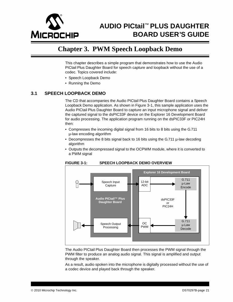
The CD that accompanies the Audio PICtail Plus Daughter Board contains a Speech Loopback Demo application. As shown in Figure 3-1, this sample application uses the Audio PICtail Plus Daughter Board to capture an input microphone signal and deliver the captured signal to the dsPIC33F device on the Explorer 16 Development Board for audio processing. The application program running on the dsPIC33F or PIC24H then:• Compresses the incoming digital signal from 16 bits to 8 bits using the G.711µ-law encoding algorithm• Decompresses the 8 bits signal back to 16 bits using the G.711 µ-law decoding
algorithm• Outputs the decompressed signal to the OCPWM module, where it is converted to
a PWM signal
FIGURE 3-1: SPEECH LOOPBACK DEMO OVERVIEW
The Audio PICtail Plus Daughter Board then processes the PWM signal through the PWM filter to produce an analog audio signal. This signal is amplified and output through the speaker.As a result, audio spoken into the microphone is digitally processed without the use of a codec device and played back through the speaker.
G.711µ-Law
Encode
12-bitADC
OCPWM
dsPIC33F
Explorer 16 Development Board
Audio PICtail™ PlusDaughter Board
Speech InputCapture
Speech OutputProcessing
G.711µ-Law
Decode
orPIC24H
nology Inc.
DS70297B-page 21
Audio PICtail™ Plus Daughter Board User’s Guide
DS70297B-page 22
The demo program consists of these basic software elements:• ADC Driver• Output Compare Module Driver• Loopback Application Software
3.1.1 ADC DriverThe ADC driver reads the incoming signal on the specified 12-bit ADC channel (either AN0 or AN3), as determined by the ADC CH SEL jumper (J9). The driver interface is specified in the ADCChannelDrv.h header file. The driver is implemented in the ADCChannelDrv.c source file.The ADC driver uses DMA Channel 0 to read data from the ADC register. The DMA channel is configured for continuous ping-pong operation, which allows the application to read one buffer while the DMA is populating the other buffer. Buffer memory must be allocated by the user-assigned application.Parameters such as instruction cycle frequency, sampling rate, buffer size and ADC module configuration are set in the ADCChannelDrv.h header file. Refer to the driver documentation on the CD for details.
3.1.2 Output Compare Module DriverThe OCPWM driver uses the Output Compare module to convert digital data to a PWM signal. Either Output Compare Channel 1 or Channel 2 can be used. The driver interface is specified in the OCPWMDrv.h header file and the driver is implemented in OCPWMDrv.c source file.The driver uses DMA Channel 1 to write data to the OCxRS register in the OCPWM module. This channel is configured for continuous ping-pong operation. The buffers for the driver must be allocated by the user-assigned application. The Timer2 module on the dsPIC33F or PIC24H device is configured for the maximum PWM time period. The driver maps the input sample value to a time period, which is then loaded into the OCxRS register. The OC output stays high until the Timer2 value matches the OCxRS register time period and then stays low for the rest of the PWM period. This way the duty cycle of the OC PWM signal is proportional to the input digital sample.Parameters such as instruction cycle frequency, sampling rate, buffer size and PWM carrier frequency are set in the OCPWMDrv.h header file. Refer to the driver documentation on the CD for details.
© 2010 Microchip Technology Inc.
PWM Speech Loopback Demo
© 2010 Microchip Tech
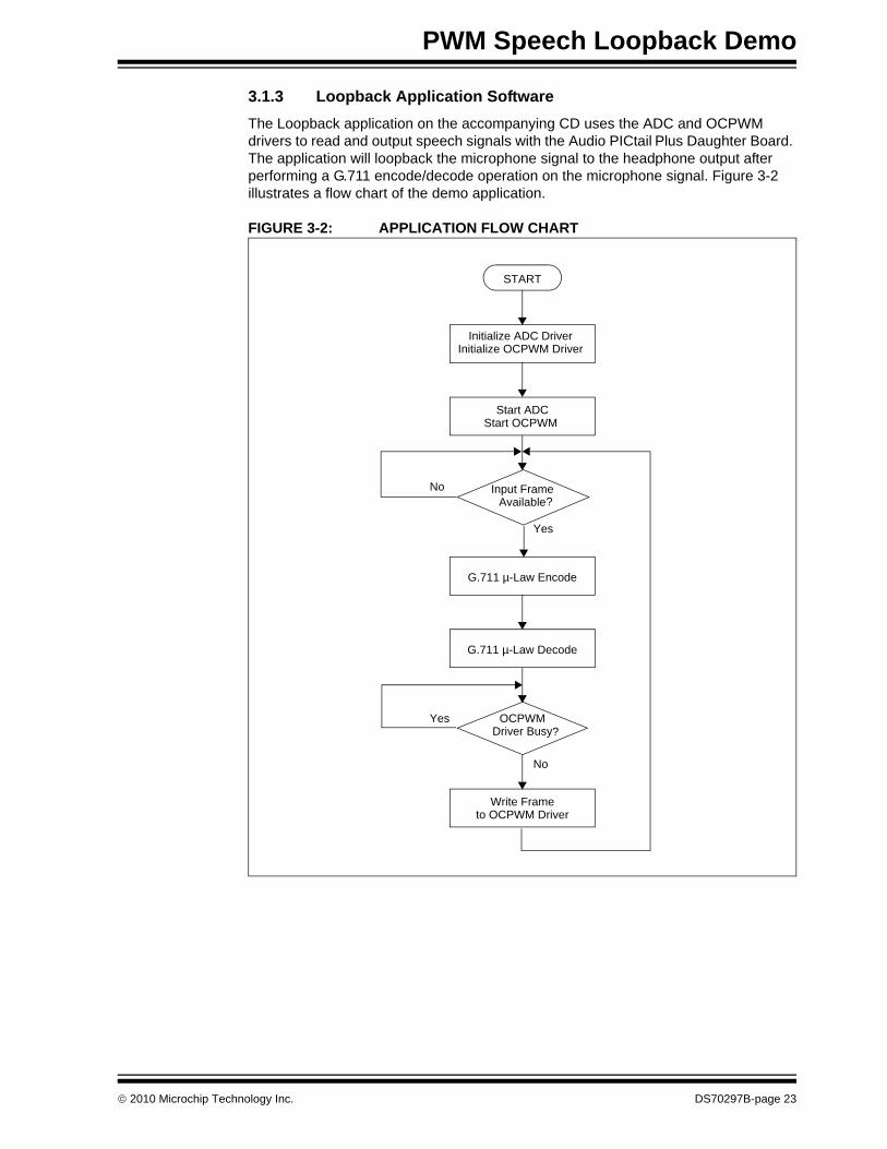
3.1.3 Loopback Application SoftwareThe Loopback application on the accompanying CD uses the ADC and OCPWM drivers to read and output speech signals with the Audio PICtail Plus Daughter Board. The application will loopback the microphone signal to the headphone output after performing a G.711 encode/decode operation on the microphone signal. Figure 3-2 illustrates a flow chart of the demo application.
FIGURE 3-2: APPLICATION FLOW CHART
START
Initialize ADC DriverInitialize OCPWM Driver
Start ADCStart OCPWM
Input FrameAvailable
G.711 µ-Law Encode
G.711 µ-Law Decode
OCPWMDriver Busy
Write Frameto OCPWM Driver
Yes
Yes
No
No
?
?
nology Inc. DS70297B-page 23
Audio PICtail™ Plus Daughter Board User’s Guide
3.2 RUNNING THE DEMO
DS70297B-page 24
To run the demo, follow these basic steps:1. Copy the demo programs from the Audio PICtail Plus Daughter Board CD to your
MPLAB project folder.2. With the Audio PICtail Plus Daughter Board plugged into the Explorer 16
Development Board, set up the Explorer 16 Development Board to run with MPLAB IDE (using either MPLAB ICE or REAL ICE).For detailed instructions on setting up the Explorer 16 Development Board, refer to the “Explorer 16 Development Board User’s Guide” (DS51589).
3. Open the demo program project in MPLAB IDE.4. Build the application and program the dsPIC33F or PIC24H device.5. Run the program.6. Connect the microphone and speaker.7. With the application running, speak into the microphone and note the resulting
playback on the speaker.
© 2010 Microchip Technology Inc.

AUDIO PICtail™ PLUS DAUGHTERBOARD USER’S GUIDE
Appendix A. Drawings and Schematics
© 2010 Microchip Tech
This appendix provides detailed technical drawings and schematic diagrams of the Audio PICtail Plus Daughter Board.
A.1 AUDIO PICtail PLUS DAUGHTER BOARD LAYOUT
Figure A-1 is a drawing of the Audio PICtail Plus Daughter Board layout.FIGURE A-1: AUDIO PICtail™ PLUS DAUGHTER BOARD LAYOUT
Audio PICtail™ Plus Daughter Card
nology Inc.
DS70297B-page 25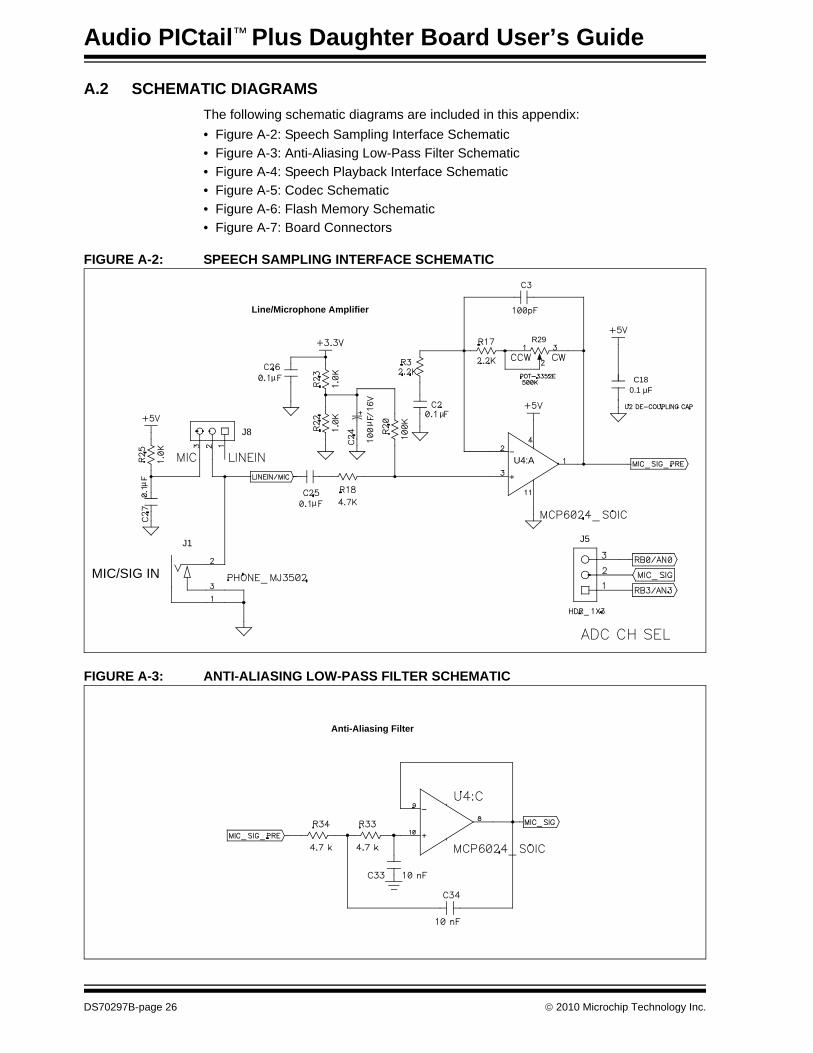
Audio PICtail™ Plus Daughter Board User’s Guide
A.2 SCHEMATIC DIAGRAMS
DS70297B-page 26
The following schematic diagrams are included in this appendix:• Figure A-2: Speech Sampling Interface Schematic• Figure A-3: Anti-Aliasing Low-Pass Filter Schematic• Figure A-4: Speech Playback Interface Schematic• Figure A-5: Codec Schematic• Figure A-6: Flash Memory Schematic• Figure A-7: Board Connectors
FIGURE A-2: SPEECH SAMPLING INTERFACE SCHEMATIC
FIGURE A-3: ANTI-ALIASING LOW-PASS FILTER SCHEMATIC
R29
U4:A
C180.1 µF
J8
MIC/SIG IN
J1 J5
Line/Microphone Amplifier
µ
µ
µ
µ
µ
Anti-Aliasing Filter
© 2010 Microchip Technology Inc.

Drawings and Schematics
FIGURE A-4: SPEECH PLAYBACK INTERFACE SCHEMATIC
FLT I/P SEL
LINE OUT
HDPHONE
VOL UP/DN
CLK
J4
O/P SEL
Line Output Amplifier
PWM Low-Pass Filter
Headphone Amplifier
DAC Differential Amplifier
µ
µ
µ
µ
µ
µ
µ
µ
µ
µ
µ
µ
µ
µ
µ
µ
© 2010 Microchip Technology Inc.
DS70297B-page 27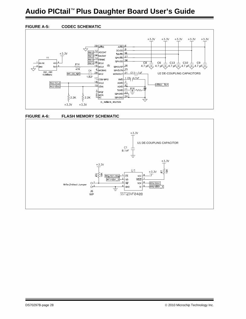
Audio PICtail™ Plus Daughter Board User’s Guide
FIGURE A-5: CODEC SCHEMATIC
FIGURE A-6: FLASH MEMORY SCHEMATIC
C84.7 µF
C64.7 µF
C134.7 µF
C104.7 µF
C94.7 µF
U2 DE-COUPLING CAPACITORS
2.2K 2.2K
U1 DE-COUPLING CAPACITOR
J6WP
µ
DS70297B-page 28
© 2010 Microchip Technology Inc.
Drawings and Schematics
FIGURE A-7: BOARD CONNECTORS
Note: The 28-pin board must operate at +3.3V when it is connected to the Audio PICtail™ Plus Daughter Board.
© 2010 Microchip Technology Inc.
DS70297B-page 29
Audio PICtail™ Plus Daughter Board User’s Guide
NOTES:
DS70297B-page 30 © 2010 Microchip Technology Inc.
AUDIO PICtail™ PLUS DAUGHTER
BOARD USER’S GUIDEIndex
AADC Driver ............................................................... 22
BBias Voltage............................................................. 13Board Layout............................................................ 25
CCodec....................................................................... 14Customer Notification Service.................................... 8Customer Support ...................................................... 8
DDAC Differential Amplifier ........................................ 14Demo Block Diagram ............................................... 21Demo Flow Chart ..................................................... 23differential signals .................................................... 11Digital Volume Control ............................................. 14Documentation
Conventions........................................................ 6Layout ................................................................. 5
FFlash Memory .......................................................... 15
GG.711 µ-Law Algorithm ............................................ 21
HHardware Components ............................................ 15
IInput Signal Line ...................................................... 13Internet Address......................................................... 8
© 2010 Microchip Technology Inc.
LLine Input ................................................................. 13Line Output Amplifier................................................ 14
MManufacturers’ Data Sheets..................................... 12Microchip Internet Web Site ....................................... 8MPLAB IDE User’s Guide .......................................... 8
OOCPWM Driver ........................................................ 22
PPing-Pong Operation................................................ 22Playback................................................................... 14PWM Output Signal.................................................. 11
RReading, Recommended ........................................... 7Readme...................................................................... 7
SSchematic Diagrams ................................................ 26Single-Ended Signal................................................. 11Speech Sampling Input ............................................ 13Speech Sampling Interface Schematic .................... 26
WWarranty Registration ................................................ 7WWW Address........................................................... 8
DS70297B-page 31
Worldwide Sales and Service
DS70297B-page 32 © 2010 Microchip Te
AMERICASCorporate Office2355 West Chandler Blvd.Chandler, AZ 85224-6199Tel: 480-792-7200 Fax: 480-792-7277Technical Support: http://support.microchip.comWeb Address: www.microchip.comAtlantaDuluth, GA Tel: 678-957-9614 Fax: 678-957-1455BostonWestborough, MA Tel: 774-760-0087 Fax: 774-760-0088ChicagoItasca, IL Tel: 630-285-0071 Fax: 630-285-0075ClevelandIndependence, OH Tel: 216-447-0464 Fax: 216-447-0643DallasAddison, TX Tel: 972-818-7423 Fax: 972-818-2924DetroitFarmington Hills, MI Tel: 248-538-2250Fax: 248-538-2260KokomoKokomo, IN Tel: 765-864-8360Fax: 765-864-8387Los AngelesMission Viejo, CA Tel: 949-462-9523 Fax: 949-462-9608Santa ClaraSanta Clara, CA Tel: 408-961-6444Fax: 408-961-6445TorontoMississauga, Ontario, CanadaTel: 905-673-0699 Fax: 905-673-6509
ASIA/PACIFICAsia Pacific OfficeSuites 3707-14, 37th FloorTower 6, The GatewayHarbour City, KowloonHong KongTel: 852-2401-1200Fax: 852-2401-3431Australia - SydneyTel: 61-2-9868-6733Fax: 61-2-9868-6755China - BeijingTel: 86-10-8528-2100 Fax: 86-10-8528-2104China - ChengduTel: 86-28-8665-5511Fax: 86-28-8665-7889China - ChongqingTel: 86-23-8980-9588Fax: 86-23-8980-9500China - Hong Kong SARTel: 852-2401-1200 Fax: 852-2401-3431China - NanjingTel: 86-25-8473-2460Fax: 86-25-8473-2470China - QingdaoTel: 86-532-8502-7355Fax: 86-532-8502-7205China - ShanghaiTel: 86-21-5407-5533 Fax: 86-21-5407-5066China - ShenyangTel: 86-24-2334-2829Fax: 86-24-2334-2393China - ShenzhenTel: 86-755-8203-2660 Fax: 86-755-8203-1760China - WuhanTel: 86-27-5980-5300Fax: 86-27-5980-5118China - XianTel: 86-29-8833-7252Fax: 86-29-8833-7256China - XiamenTel: 86-592-2388138 Fax: 86-592-2388130China - ZhuhaiTel: 86-756-3210040 Fax: 86-756-3210049
ASIA/PACIFICIndia - BangaloreTel: 91-80-3090-4444 Fax: 91-80-3090-4123India - New DelhiTel: 91-11-4160-8631Fax: 91-11-4160-8632India - PuneTel: 91-20-2566-1512Fax: 91-20-2566-1513Japan - YokohamaTel: 81-45-471- 6166 Fax: 81-45-471-6122Korea - DaeguTel: 82-53-744-4301Fax: 82-53-744-4302Korea - SeoulTel: 82-2-554-7200Fax: 82-2-558-5932 or 82-2-558-5934Malaysia - Kuala LumpurTel: 60-3-6201-9857Fax: 60-3-6201-9859Malaysia - PenangTel: 60-4-227-8870Fax: 60-4-227-4068Philippines - ManilaTel: 63-2-634-9065Fax: 63-2-634-9069SingaporeTel: 65-6334-8870Fax: 65-6334-8850Taiwan - Hsin ChuTel: 886-3-6578-300Fax: 886-3-6578-370Taiwan - KaohsiungTel: 886-7-536-4818Fax: 886-7-536-4803Taiwan - TaipeiTel: 886-2-2500-6610 Fax: 886-2-2508-0102Thailand - BangkokTel: 66-2-694-1351Fax: 66-2-694-1350
EUROPEAustria - WelsTel: 43-7242-2244-39Fax: 43-7242-2244-393Denmark - CopenhagenTel: 45-4450-2828 Fax: 45-4485-2829France - ParisTel: 33-1-69-53-63-20 Fax: 33-1-69-30-90-79Germany - MunichTel: 49-89-627-144-0 Fax: 49-89-627-144-44Italy - Milan Tel: 39-0331-742611 Fax: 39-0331-466781Netherlands - DrunenTel: 31-416-690399 Fax: 31-416-690340Spain - MadridTel: 34-91-708-08-90Fax: 34-91-708-08-91UK - WokinghamTel: 44-118-921-5869Fax: 44-118-921-5820
01/05/10
chnology Inc.
Related Documents