Republic of Iraq Ministry of Higher Education and Scientific Research Al-Nahrain University College of Science Audio-Hiding System Using Wavelet and DCT Transforms A Thesis Submitted to the College of Science, Al-Nahrain University in Partial Fulfillment of the Requirements for The Degree of Master of Science in Computer Science By Noura Qusay Ebraheem (B.Sc. 2005) Supervised By Dr. Loay E. George October 2008 Shwal 1429

Welcome message from author
This document is posted to help you gain knowledge. Please leave a comment to let me know what you think about it! Share it to your friends and learn new things together.
Transcript

Republic of Iraq Ministry of Higher Education and Scientific Research Al-Nahrain University College of Science
Audio-Hiding System Using Wavelet and
DCT Transforms
A Thesis Submitted to the College of Science, Al-Nahrain
University in Partial Fulfillment of the Requirements for
The Degree of Master of Science in Computer
Science
By
Noura Qusay Ebraheem (B.Sc. 2005)
Supervised By
Dr. Loay E. George October 2008 Shwal 1429

بسم االله الرحمن الرحيم
عَلَّمَ الَّذِي عَلَّمَ بِالْقَلَم اقْرَأْ وَرَبُّكَ الْأَآْرَمُ
الْإِنسَانَ مَا لَمْ يَعْلَمْ
صدق االله العظيم
سوره العلق
٤ ٣
٥
Dedication
To my parents
To all my family To all friends With my Love
Noura

Acknowledgment First of all great thanks are due to Allah who helped me and gave me the
ability to achieve this research from first to last step.
I would like to express my sincere appreciation to my supervisor, Dr. Loay A.
George, for giving me the major steps to go on to explore the subject, shearing with me
the idea in my research "Adaptive Audio-audio Hiding System Using Wavelet and
DCT Transform" And perform the points that I felt important.
Also grateful thanks for the Head of Department of Computer Science Dr.
Taha S. Bashaga.
Deep gratitude and special thanks to my family: my Mother, Father, Sister and
Brother for their encouragements and supporting to succeed in doing this work.
Deep thanks for all my friends and every one support me, encourage me and
giving me advises.

Abstract Steganography is considered as one of the widely used methods for hiding
information; it hides secret data in digital cover data without clear suspicion.
This work focus on using two transform based methods for hiding secret data.
First, the data will converted to binary form, then two predefine threshold values are
used to categorize the audio blocks. The first threshold is used to decide whether the
block is voiced/unvoiced, and the second threshold is used to decide which transform
will be used on the voiced blocks only (i.e., DCT or Wavelet).
Second, the audio signal will be transformed by the chosen one of transforms;
DCT transform will applied on voiced blocks that have energy less than second
threshold value, and wavelet transform will be applied on voiced blocks that have
energy grater than or equal to the second threshold value. In the third stage the
embedding on secret data on voiced blocks is applied.
The performance of the proposed hybrid system was tested by using some
fidelity measures (MSE, MAE, and PSNR) to measure the rate of error, the ratio of
corrected retrieved bits and the hiding rate, the later is computed to assess the
embedding power of system. Also, the effects of some control parameters on the
system performance were investigated to assist user to correctly choose the proper
values of the system parameters, some of these parameter is the threshold value
which classify the blocks to voice/unvoiced, and our goal is to hide in voiced blocks,
this will provide high hiding rate for the system.

List of Abbreviations A/D Analog to Digital converter
D/A Digital to Analog converter
dB Decibel
DCT Discreet Cosine Transform
DFT Discreet Fourier Transform
DHWT Discreet Haar Wavelet Transform
HAS Human Audio System
HCB Hiding in Checked Blocks
HVB Hiding in Voiced Blocks
HWT Haar Wavelet Transform
Hz Hertz
FFT Fast Fourier Transform
IDCT Inverse Discreet Cosine Transform
IHWT Inverse Haar Wavelet Transform
kB Kilo Byte
KHz Kilo Hertz
LBE Low Bit Encoding
LSB Least Significant Bits
MB Mega Byte
MAE Mean Absolute Error
MSE Mean Square Error
PCM Pulse Code Modulation
PSNR Peak Signal to Noise Ratio
RIFF Resource Interchange File Format
SNR Signal to Noise Ratio
WAV Windows Audio Visual

List of Symbols Symbol Description
BlkLen Block Length
C Transform Coefficient
ExSec Vector contain the extracted bit of secret message
ER Error of corrective Retrieved bits
HR Hiding Rate
i Counter
N Length of voiced block
NoSamp total number of audio samples
Q Quantization Step
qWv vector contain data after Quantization
rWv vector contain the reconstructed Wave file
S value of embedded secret bit
Scr vector contain Secret Data
Stg vector contain Stego data
T Power Threshold value
T' Transform Threshold value
tWv vector contain the transformed data
v pointer
Wv vector contain audio wave file data
δ Modulation Step

Table of Contents
Chapter One: General Introduction
1.1 Overview --------------------------------------------------------------------------------- 1
1.2 Information Hiding ---------------------------------------------------------------------- 1
1.3 Steganography ---------------------------------------------------------------------------- 3
1.3.1 Steganography Versus Watermark --------------------------------------------- 4
1.3.2 Steganography Versus Cryptography ------------------------------------------
1.4 Digital Audio ----------------------------------------------------------------------------
5
6
1.5 Related Work ---------------------------------------------------------------------------- 6
1.6 Aim of Thesis ---------------------------------------------------------------------------- 9
1.7 Thesis Layout ---------------------------------------------------------------------------- 9
Chapter Two: Theoretical Background
2.1 Introduction ------------------------------------------------------------------------------- 11
2.2 Steganography --------------------------------------------------------------------------- 11
2.3 Steganography History ----------------------------------------------------------------- 12
2.3.1 Old steganographic techniques -------------------------------------------------- 12
2.3.2 Modren Steganographic techniques --------------------------------------------- 13
2.4 Steganography Requirements ---------------------------------------------------------- 13
2.5 Steganographic techniques ------------------------------------------------------------- 15
2.5.1 Steganography Classification based on I/O ------------------------------------ 15
A. Pure Steganography ------------------------------------------------------------ 15
B. Secret Key Steganography ---------------------------------------------------- 15
C. Public Key Steganography ---------------------------------------------------- 16
2.5.2 Steganography Classification based Stego media ----------------------------- 16
A. Hiding in Text ------------------------------------------------------------------- 17
B. Hiding in Image ----------------------------------------------------------------- 18

C. Hiding in Audio ----------------------------------------------------------------- 19
2.6 Audio Steganography ------------------------------------------------------------------- 22
2.6.1 Types of Audio Files -------------------------------------------------------------- 22
2.7 Digital Sound Representation ---------------------------------------------------------- 24
2.8 Transform Domain Embedding Techniques ----------------------------------------- 27
2.8.1 Fourier Transform ---------------------------------------------------------------- 28
2.8.2 DCT Transform ------------------------------------------------------------------- 28
2.8.3 Wavelet Transform --------------------------------------------------------------- 29
2.9 Haar Wavelet Transform (HWT) ------------------------------------------------------ 30
2.10 Fidelity Measure ----------------------------------------------------------------------- 34
2.10.1 Mean Squared Error (MSE) ---------------------------------------------------- 34
2.10.2 Peak Signal-to-noise Ratio ----------------------------------------------------- 34
2.10.3 Signal-to-noise Ratio ------------------------------------------------------------ 35
Chapter Three: System Development
3.1 Introduction ------------------------------------------------------------------------------- 37
3.2 Audio File ---------------------------------------------------------------------------------37
3.3 The Overall System Module ------------------------------------------------------------ 38
3.3.1 Hiding Module -------------------------------------------------------------------- 38
3.3.1.1 Input Audio File ----------------------------------------------------------- 40
3.3.1.2 Voiced / Unvoiced Segmentation --------------------------------------- 41
3.3.1.3 Transformation ------------------------------------------------------------- 43
3.3.1.4 Quantization/ Dequantization ---------------------------------------------47
3.3.1.5 Data Embedding ------------------------------------------------------------
48
3.3.1.6 Inverse Transform --------------------------------------------------------- 50
3.3.1.8 Reconstruction of Stego Cover File ------------------------------------- 52
3.3.2 Extraction Module ---------------------------------------------------------------- 52

3.3.2.1 Load Audio File ------------------------------------------------------------ 52
3.3.2.2 Voiced /Unvoiced Segmentation ----------------------------------------- 52
3.3.2.3 Transformation --------------------------------------------------------------54
3.3.2.4 Extraction of the Embedded Data ---------------------------------------- 54
Chapter Four: Experimental Result
4.1 Introduction -------------------------------------------------------------------------------55
4.2 Test Measures ---------------------------------------------------------------------------- 55
A. Fidelity Measures -------------------------------------------------------------------- 55
B. Hiding Rate (HR) -------------------------------------------------------------------- 55
C. Ratio of Correctly Retrieved Secret Bits (ER) ----------------------------------- 56
4.3 Test Samples ----------------------------------------------------------------------------- 56
4.4 Test Results and Discussion ------------------------------------------------------------ 57
4.4.1 Threshold Value (Thr) ------------------------------------------------------------58
4.4.2 Quantization Step (Q) ------------------------------------------------------------ 59
4.4.3 Block Length ---------------------------------------------------------------------- 61
4.5 Performance Comparison --------------------------------------------------------------- 61
Chapter Five: Conclusions and Suggestions
5.1 Introduction ------------------------------------------------------------------------------- 64
5.2 Conclusions ------------------------------------------------------------------------------- 64
5.3 Suggestions ------------------------------------------------------------------------------- 65
List of References
Appendix A (WAV File Format)


Chapter One
General Introduction
1.1 Overview With the development of information technology, people have paid more and
more attention on the information security today because internet provides the
facilities to exchange text, image, audio, and video between users. Internet access can
reach sensitive locations (like, martial location, ministry of defense, etc) for each
government in the world, because it becomes the most public way to link with large
companies and banks in the world.
All these facts encouraged some persons (or even companies) to develop ways
to some software tools to make unauthorized access to closed locations [Kaw06]. So
for this reason information hiding becomes the focus of the information security
research because it is the more suitable clue, than encryption, to conceal information.
Information hiding technology can embed secret information into a digital
media source without impairing the perceptual quality of that source, such that other
people can’t feel this secret information. So the secret key, the signature or the
private data can be exchanged securely through Internet [Xiu07].
1.2 Information Hiding Information hiding techniques have received very much less attention from the
research community and from industry than cryptography. However, this situation
was changed rapidly since the first academic conference on this topic, which was
organized in 1996. The main driving force was concentrated on protecting the
copyright of audio, video and other works which become available in digital form,
the ease with which perfect copies can be made may lead to large-scale unauthorized
copying, and this is of great concern to the music, film, book and software publishing

industries. At the same time, the movements that conducted by various governments
to restrict the availability of encryption services have motivated people to study
methods by which private messages can be embedded in seemingly innocuous cover
messages [Fab99]. So the hidden data may have no relationship with (or may provide
important information about) the cover-object, in which it is embedded [Cac00]. The
classification of data hiding techniques is presented in Figure (1.1)
Fig (1.1) A classification of information hiding techniques [Fab99]
Data hiding techniques should be capable of embedding data in a host signal
with the following restrictions and features [Ben96]:
1. The host signal should be non objectionally degraded, and the embedded data
should be minimally perceptible. This means that the observer should not notice
the presence of the data, even if it is perceptible.
2. The embedded data should be directly encoded into the media, rather than into a
header, so that the data remain intact across varying data file formats.
3. The embedded data should be immune to modifications ranging from intentional
and intelligent removal attempts, to anticipated manipulations (e.g., channel noise,
resampling, encoding, lossy compression, digital-to-analog (D/A) conversion,
etc).

4. The embedded data should be self-clocking or arbitrarily reentrant. This ensures
that the embedded data can be recovered when only fragments of the host signal
are available.
1.3 Steganography Steganography is the art and science of writing hidden message in such a way
that no one apart from the intended recipient knows of the existing of the message;
this is in contrast to cryptography, where the existence of the message itself is not
disguised, but the content is obscured [Cum04]. The word "Steganography" is hard to
be found in any dictionary, it comes from the Greek word "Steganos" (means
Covered) and "graphy" (means writing). So steganography literally means "Covered
Writing" [Kaw06].
Generally, a steganography message will appear to be something else: a
picture, an article, a shopping list, or some other type of messages. Classically, it may
be hidden by using invisible ink between the visible lines of innocuous documents, or
even written onto clothing, thus forming a message. It may even be a few words
written under a postage stamp, the stamp then being the covertext [Kes01].
The advantage of steganography over cryptography alone is that messages do
not attract attention to themselves, to messengers, or to recipients. An unhidden
coded message, no matter how unbreakable it is, will arouse suspicion and may in
itself be incriminating, as in some countries encryption is illegal [Cum04]. So the
goal of steganography is to avoid drawing attention to the transmission of a hidden
message. If suspicion is raised, then this goal is defeated [Sib04].
1.3.1 Steganography versus Watermark [Moh04] The purpose of both watermarking and steganography is to hide a message in a
carrier signal, but the differences between them are summarized in table (1.1).
Table (1.1) A comparison between watermark and steganography [Moh04]

Watermark Steganography The information hidden by a watermarking system is always related to the original object (to be protected) or to its owner.
Steganographic system just hides any information.
Communications are usually one-to-many (between sender and many receivers).
Communications are usually point-to-point (between sender and receiver).
The cover is the transmitted data, and the hidden information is just for authentication purposes.
The hidden information is the transmitted data, and the cover is just to hide it.
Small amount of data need to be hidden.
Any amount of data needs to be hidden.
The hidden data need more robustness because watermarking concerns with potential removal by a pirate.
The hidden data need less robustness, because steganography is mainly concern with the problem of detecting a message in the stego object.
1.3.2 Steganography versus Cryptography There is a clear distinction between steganography and cryptography, and
inspite of the inherent difference between them they are compliment to each other
very well. The aim of cryptography is to scramble the message with the help of a key
so that the message becomes meaningless to the attacker, but can only be deciphered
by either the same key or another key. However steganography does not allow us to
change the message itself, rather the message is hided in seemingly innocuous
messages like text, picture or other media. So, in this case the attacker does not know
if the two parties are even exchanging messages [Bak07].
Generally the purpose of both steganography and cryptography is to provide
secret communication, but the differences between them are summarized in table
(1.2) [Moh04].
Table (1.2) A comparison between Cryptography and steganography [Bak07]

Cryptography Steganography The goal of secure cryptographic method is to prevent an interceptor from gaining any information about the plaintext from the intercepted cipher text.
The goal of secure steganographic methods is to prevent intermediate observer from even obtaining knowledge about the mere presence of the secret data.
The system is broken when the attacker can read the secret message.
Breaking a steganography system has two stages: 1. The attacker can detect the
type of steganography has been used.
2. He should be able to read the embedded message.
The cryptographic systems don't use the steganography methods.
In many steganography systems the embedded message is encrypted before hiding.
1.4 Digital Audio [Cyb87] Over the years, improvements in technology have changed the way music is
recorded and the media used. Today, we use computers to record audio and save it to
CDs, MP3 players, and other storage devices.
In order to transform sound into a digital format, the sound should be sampled.
This process takes place while there is digital recording. The computer takes a
snapshot of the sound level at small time intervals. The number of samples taken each
second is called the sampling rate. The more samples that are taken, the better sound
quality. For instance, audio sampled at 44 kHZ is better than audio sampled at 22
kHz. It also means more storage space for higher quality sound.
Audio files have an extension at the end of the filename that tells users the
format type. For example, files with (.snd) or (.aiff) are common on Macintosh
computers while .wav is most common on Windows machines. Therefore, it is
important to know the file format extensions.

1.5 Related Work A lot of research works were conduct to develop many Information hiding
techniques, the researchers tried to insert new additional features to increase the
system robustness and invisibility. Some of the published researches are summarized
below:
1. Areespongsa (2000) [Are00], presented a stegosystem using wavelet transform. In
this system the data was embedded in the sign of the high frequency coefficients
of the cover image in attempt to trade off between the robustness of the embedded
data and the invisibility of the stegoimage.
2. AL- Ta'l (2002) [Ziy02] developed an algorithm for audio steganography
depending on the Human Auditory System (HAS). One of the properties of the
HAS is the masking effect which depends on the principle that "loud sound tends
to mask out quiet ones". Quieting the secret audio message to be masked by loud
audio cover could be used for hiding purpose. A reverse procedure is done for
extracting the audio message. The work was not for audio copyright purpose, it
was used for the purpose of secret transmission without drawing any suspicion
that a message is hidden in the cover audio file. The secret message and the cover
may be speech, music or any recorded voices. The weak point in this algorithm is
that the original audio signal must be sent to the receiver.
3. Xu, et al. (2003) [Jia03], they proposed a system for "text steganography using
wavelet transform". This research implies an algorithm to limit errors in lossy
transform, and to achieve high capacity text hiding in image files using discrete
Haar wavelet transform (DHWT). They have discussed robust text steganography
using multiple-level lossless DHWT. The experimental results validated the
method for high capacity plain text hiding and demonstrated that lossless recovery
of the hidden text from JPEG images with compression rate as high as 67% is
possible.
4. AL Baka'a (2003) [Bak03], was concerned with development of invisible
watermarking techniques, and had tested their robustness against different attacks
(rotation, sharpening, brightness and JPEG compression). Two approaches for
image watermarking were developed, the first one embed the digital watermark
data in the spatial domain, while the second approach embeds watermark data in
frequency domain using DCT.
5. Dieab (2003) [Die03], presented an audio watermarking system in order to embed
a 10 characters digital watermark in the audio signal. The system uses two
different techniques; low bit encoding (LBE) in the time domain, and the human
auditory characteristics in the frequency domain using Fast Fourier Transform
(FFT).
6. Majeed (2004) [Maj04], introduced a steganography system that hides audio in
audio using Discrete Cosine Transform (DCT). He suggested six hiding methods;
some of them dedicated to hide audio data in audio data, while others have the
ability of hiding any type of secret data in audio data. Also, he applied some
additional steps to increase the security immunity of the system using two kinds of
encryption: Pure key steganography and private key steganography.
7. AL Kawaz (2006) [Kaw06] had proposed a system for "low rate hiding in audio
data using phase domain". This research implies an algorithm for hiding any
secret data type in the audio signal. The audio signal is transformed from time
domain to frequency domain using a new mechanism for determining Fourier
transform, in this introduced mechanism a reduction in the number of
mathematical operations is achieved, which consequently leads to significant
reduction in computation time. Two hiding method were designed to embed secret
data bits in the phase domain coefficients of the audio signal. The first method,
called hiding in voiced blocks (HVB), implies the insertion of secret bits in the
voiced parts of audio data. While the second method, called hiding in checked
blocks (HCB), implies the insertion of secret bits in audio blocks which are
successfully passed the retrieved bits integrity tests.
The test results indicated that the HVB method show more embedding
capacity than HCB method, and a little amount of the embedded secret bits could
incorrectly retrieved when HVB method is utilized.
1.6 Aim of Thesis The aim of research work is to develop a system for hiding audio signal in
another audio signal using both Wavelet and DCT transform. The embedding method
is done on the transform coefficients of the cover audio signal that produced after
applying either wavelet or DCT transform. Since each transform type have its points,
which are different with those belong to other transform, so a hybrid transform
coding scheme will be established to overcome the weak aspect may phase the coding
task when single type of transform is used. So the behavior of the established hybrid
system should be better, but the scheme will be more complicated.
1.7 Thesis Layout In addition to chapter one, the remaining part of this thesis consists of the
following chapters:
• Chapter Two (Theoretical Background)
In this chapter a background to the audio file (format and types) is presented,
and some of the audio steganography techniques and transform coding methods
are illustrated.
• Chapter three (System Development)
It is dedicated to introduce the design aspects of the proposed system, and
the implementation steps to realize the system. Each implementation step is
clarified with its related algorithms.
• Chapter four (Experimental Results)

This chapter contains the results of the comprehensive tests performed on the
proposed system using different test samples.
• Chapter five (Conclusions and Suggestions)
This chapter is dedicated to list the conclusions that derived from the
analysis of test results; also some ideas for future work are given in this chapter.


Chapter Two Theoretical Background
2.1 Introductions This chapter is concerned with the theoretical concepts of information hiding,
which is main objective in this project, and discuss the existing techniques of hiding
in different media (such as, hiding in text, image and audio). Then some of the
relevant issues to audio steganogrphy techniques are reviewed, including the basics
of digital audio and the structure of the wave file that used as cover media. Then,
definition of the transform and some of its types are given.
2.2 Steganography The following formula provides a very generic description of the pieces of the
steganographic processes:
cover_medium + hidden_data + stego_key = stego_medium
In this context, the cover_medium is the file in which the hidden_data is
embedded, which may also be encrypted using the stego_key. The resultant file is the
stego_medium (which will, of course, be the same type of the cover_medium). The
cover_medium and, stego_medium are typically image, audio or text files [Gar01]. In
this chapter a focus is set toward audio files, and they will be called the cover_audio
or stego_audio.
2.3 Steganography History Steganography is an old issue, and some of its methods are old, and others are
modern techniques.

2.3.1 Old Steganographic Techniques Steganography had been widely used in historical times, especially before
cryptographic systems were developed. Examples of historical usage include:
• Hidden messages in wax tablets: in ancient Greece, people wrote messages on the
wood, and then covered it with wax so that it looked like an ordinary, unused
tablet.
• Hidden messages on messenger's body: also in ancient Greece. Herodotus tells the
story of a message tattooed on a slave's shaved head, hidden by the growth of his
hair, and exposed by shaving his head again. The message allegedly carried a
warning to Greece about Persian invasion plans.
• Hidden messages on paper written in secret inks under other messages or on the
blank parts of other messages.
2.3.2 Modern Steganographic Techniques [Ras02]
Modern steganography entered the world in 1985 with the advent of the
Personal Computer, and it is applied to classical steganography problems. The
development following that was slow: Some of new steganography techniques are:
• Concealing messages within the lowest bits of noisy images or sound files.
• Concealing data within encrypted data. The data to be concealed is first encrypted
before being used to overwrite part of a much larger block of encrypted data. This
technique works most effectively where the decrypted version of data being
overwritten has no special meaning or use: some cryptosystems, especially those
designed for file systems, add random looking padding bytes at the end of a
ciphertext so that its size cannot be used to figure out the size of the original
plaintext.
• Concealing messages in tampered executable files, exploiting redundancy in the
i386 instruction set.
• Embedding pictures in video material (optionally played at slower or faster
speed).

2.4 Steganography Requirements [Ras02]
Steganography have to guarantee these requirements: 1. Robustness: the embedded information is said to be robust if its presence can
be reliably detected after applying modification, to certain extent, on the host
(stegocover) object.
2. Undetectability: the embedded information is undetectable, if the stego
object, with the embedded message, is consistent with the model of the source
from which the stego object is drawn.
3. Perceptual transparency: it is based on the properties of the human visual
system or the human audio system. The embedded information is
imperceptible if an average human subject is unable to distinguish between
carriers that do contain hidden information and those do not.
The above mentioned requirements are mutually competitive and cannot be
clearly full filled at the same time. If we want to hide a large message inside an
image, we cannot require at the same time absolute undetectability and large
robustness. A reasonable compromise is always a necessity. On the other hand, if
robustness to large distortion is an issue, the message that can be reliably hidden
cannot be too long. This observation is schematically illustrated in Figure (2.1).
Fig (2.1) Conflicting requirements [Ras02]
2.5 Steganographic Techniques

Steganography techniques can be divided into various categories according to
various criteria. The basic and most common used classification criteria are based on
the nature of the cover media (i.e, text, audio, video, packets, OS) or on the nature of
hiding media (i.e, spatial domain, frequency domain and parametric domain
steganography).
Another way for the categorization of steganography methods is based on the
condition "whether or not they use the original data for extraction of hiding message"
from tested data [Sel99].
2.5.1 Steganography classification based on I/O According to the nature of inputs and output, there are three types of
steganography methods: a. Pure Steganography [Joh01]
A steganographic system does not require the prior exchange of some secret
information (like a stego-key) is called Pure steganography. Formally, the
embedding process can be described as a mapping E: C×M C', where C is the
set of possible cover, and M is the set of possible messages. The extraction
process consists of a mapping D:C' M, that is extracting the secret message out
of a cover.
In some steganography systems, the extraction process needs the original
cover also. Both sender and receiver must have access to the embedding and
extraction algorithm, but the algorithms should not be public. b. Secret Key Steganography [Joh01]
With pure steganography, no information (apart from the functions E and D)
is required to start the communication process; the security of the system thus
depends entirely on its secrecy. In practice this is not very secure; one may assume
that the attacker knows the algorithm that the sender and receiver use for
information transfer. Thus, the security of steganographic system should rely on
some secret information traded by the sender and the receiver (i.e. the stego-key).

Without knowledge of this key, nobody should be able to extract secret
information out of a cover.
A secret key steganography system is similar to a symmetric cipher. (i.e.,
the sender chooses a cover C and embeds the secret message into C using a secret
key K). If the key used in the embedding process is known to the receiver, the
receiver can reverse the process and extracts the secret message. Anyone who
does not know the secret key should not be able to obtain evidence about the
encoded information. c. Public Key Steganography
In public key steganography, it is not necessary for two people to share a
secret key to establish a secure channel. Each one needs to know the other's public
key. This suggests a possible approach to steganography in which a secret key
does not have to be agreed upon between the sender and the receiver. Some
information must still be known a priori, where each one must know the other's
public key; from a practical perspective this is a much more reasonable
requirement [Cra98]. One way to build public key steganography system is the use
of public key cryptosystem [Joh01].
2.5.2 Steganography Classification Based on Stego Media
Information hiding techniques are classified according to the media where the
information is hidden:
A. Hiding in Text Methods like line-shift coding, word shift coding, and feature coding are the
most commonly used methods to hide data in text. When using a text data as a host
media, the embedded data is usually a codeword that is hidden within the text by
altering its different textual features. The three methods mentioned above determine
what feature is to be changed. To encode the codeword [Sel99], each bit of codeword
is embedded using one of the above methods: 1. Line-Shift Coding

Line-shift coding is very easy to perform, and is considered as the most
resistant to degradation due to copying. Although this method withstand copying,
the human eye and other measurements can easily detected it. It can also be easily
defeated through replacing or reformatting of the text [Sel99]. 2. Word-Shift Coding
Word-shift coding can also be easily done. The appearance of natural
spacing must be maintained in order not arouse suspicion. By determining the
location where unnatural spacing has occurred, the encoded bits can be revealed
[Bri06]. 3. Feature Coding
Feature coding is another way of embedding data into a text file. In feature
coding, certain text features are altered depending on the embedded data [Sel99].
In order for this type of feature coding to work, the text must be altered by
randomness which will make the text look less suspicious to its readers. This type
of feature coding can be easily defeated if the vertical line length is adjusted to a
fixed length before the file is opened [Dav00].
B. Hiding in Image
Text files are not the only files that can be used for host data. Images are also
another popular source for hidden data. The most popular techniques include least
significant bit insertion and the use of algorithms and transformations [Aud03]. 1. Least Significant Bit Insertion
Least significant bit insertion, or LSB, is one of the most common
techniques used to hide information in images. When working with 24-bit pixel
images, three bits can be encoded into each pixel. Because the least significant bits
are the ones being altered, the change is difficult to determine by the viewer.
However, when working with 8-bit pixel images, this method becomes harder to
implement because a change of a bit may result in a change of an entirely different
colors. Although this technique is popular due to its simplicity, it is also one of the

easiest methods to accidentally alter [Sel99]. Although it is almost an exact replica
of the original image, the bits from the original image cannot be guaranteed. 2. Algorithm and Transformations
Other algorithms and transformations are also used when dealing with
images and their usage in hiding data. Some of the most popular methods are the
patchwork method, the discrete cosine transform (or DCT), and the Fourier
transform. The patchwork method takes the advantage of the fact that the human
eye cannot easily detect varying amount of light [Kat00]. The patchwork method
gets its name from "using redundant pattern encoding to repeatedly scatter hidden
information throughout the cover image" [Sel99]. One advantage of this technique
is that it can hide a small message many times throughout an image. Because of
this, even when an image is cropped or rotated, the chances of one instance of the
encoded message still being intact are very high.
There are many different transforms used to map image data to non-spatial
domain, such that the data hiding (embedding) could be done in more robust way.
Among these transforms are discrete cosine transform, wavelet transform, the
Fourier transform.
The discrete cosine transform (DCT) maps the image data into a set of
coefficients that allows a small set of cosine functions approximates a portion of
the image [Yan01]. For example, the JPEG standard compression schema uses
8x8 blocks of pixels and approximates them with a set of cosine functions, each
set can approximate a section of the image. The DCT finds the value of the weight
coefficient for each cosine function, so that the weighted sum of the functions
added up to recreate the original 8x8 block of pixels [Yan01].
The wavelet transform and Fourier transform methods use complicated
mathematical formulas in order to find the coefficients values required to map a
signal into the frequency domain [Kat00].
C. Hiding in Audio

Audio file can also be used to hide information. Steganography is often used to
copyright audio file to protect the rights of music artists. Techniques such as least
significant bit insertion, phase coding, spread spectrum coding, and echo hiding can
be used to protect the content of audio file. The biggest challenge face all these
methods are the sensitivity of human auditory system or HAS [Kat00]. Because the
HAS is so sensitive, people can often pick up randomly added noise which making it
hard to successfully hide data within audio data. To fully understand the different
techniques of hiding information in audio data, transmission of audio signals must
first be understood. When working in audio the transmission medium must always be
considered.
The transmission medium of an audio signal refers to the environment in which
a signal might go through to reach its destination. The possible transmission
environments can be categorized into the following four groups [Bri06]:
1. Digital end-to-end environment, where the sound files are copied directly
from one machine to another.
2. Increased/decreased resampling environment, where the signal is resampled
to a higher or lower sampling rate.
3. Analog transmission and resampling, where a signal is converted to analog
state, played on a clean analog line, and resample.
4. "Over the air" environment, where the signal is played into the air, pass
through a microphone.
By understanding the different mediums in which audio signals may travel,
the appropriate technique for embedding data in audio files can be determined. The
most commonly used methods for hiding data in audio media are the following
methods:
1. Least significant Bit Insertion
Like image file, the least significant bit insertion method can also be used to
store data in the least significant bit of audio file. However, like image file the
hidden data, using LSB, can be easily destroyed and detected. Resampling and
channel noise may alter the hidden data, while changing the least significant bit
may introduce audible noise [Sel99]. Information may also be destroyed through
compression, cropping, or A/D, D/A conversion [Yan01].
Although this technique is simple to perform, its lack of dependability makes
other methods more appealing. 2. Phase Coding
The phase coding method works by substituting the phase of an initial audio
segment with a reference phase that represents the data. The phase of subsequent
segment is adjusted in order to preserve the relative phase difference between
segments [Yan01].
Phase coding is one of the most effective coding methods in terms of the
signal-to-perceived noise ratio. When the phase relation between each frequency
component is dramatically changed, noticeable phase dispersion will occur.
However, as long as the modification of the phase is sufficiently small
(sufficiently small depends on the observer; professionals in broadcast radio can
detect modifications that are imperceivable to an average observer), an inaudible
coding can be achieved [Ben96]. 3. Spread Spectrum Coding
In a normal communication channel, it is often desirable to concentrate the
information in as narrow region of the frequency spectrum as possible in order to
conserve available bandwidth and to reduce power. The basic spread spectrum
technique, on the other hand, is designed to encode a stream of information by
spreading the encoded data across as much of the frequency spectrum as possible.
This allows the signal reception, even if there is interference on some frequencies
[Ben96]. 4. Echo Data Hiding
Echo data hiding embeds data into a host audio signal by introducing an
echo [Kat00]. The data are hidden by varying three parameter of the echo: initial

amplitude, decay rate, and offset. As the offset (or delay) between the original and
the echo decreases the two signals blend. At a certain point, the human ear cannot
distinguish between the two signals. This point is hard to determine exactly, it
depends on the quality of the original recording, the type of sound being echoed,
and the listener. In general, it was found that this fusion occurs around 1/1000 of a
second for most sounds and most listeners. The coder uses two delay times, one to
represent a binary one (offset) and another to represent a binary zero (offset +
delta). Both delay times are below the threshold at which the human ear can
resolve the echo [Ben96].
2.6 Audio Steganography Data hiding in audio signals exploits imperfection of human auditory system
known as audio masking. In presence of a loud signal (masker), another weaker
signal may be inaudible, depending on spectral and temporal characteristics of both
masked signal and masker. So the embedded signal is hidden there, besides
transparency of the embedding process, it is important to insure robustness of the
embedded signal.
2.6.1 Types of Audio Files As with other digital media, a number of file types are in use for storage of
digital audio data. When selecting a file type, it is important to consider the
universality of the file type and thus its readability by a variety of software programs.
File types that are proprietary and not likely to be supported in the future should be
avoided, some of well knows audio file types are listed below:
1. WAV: This file type was developed by Microsoft. It is in widespread use, and is
readable by most of audio software programs. The WAV file type has become a
standard and is recommended. In addition, the WAV file type is also available in a
professional format (i.e, broadcast WAV, BWF), which has the capability to store
metadata in the file header. Although not all audio software programs are

currently capable of reading or writing to the metadata header, the BWF format is
emerging as the WAV file type of preference for archival audio projects.
2. MP3: Is the name of the file extension and also the name of the type of file for
MPEG, audio layer 3. Layer 3 is one of three coding schemes (layer 1, layer 2 and
layer 3) for the compression of audio signals. Layer 3 uses perceptual audio
coding and psychoacoustic compression to remove all superfluous information
(more specifically, the redundant and irrelevant parts of a sound signal. The stuff
the human ear doesn't hear anyway). It also adds a MDCT (Modified Discrete
Cosine Transform) that implements a filter bank, increasing the frequency
resolution 18 times higher than that of layer 2. Layer 3 can shrink the original
sound data from a CD (with a bit rate of 1411.2 kilobits per one second of stereo
music) by a factor of 12 (i.e., down to 112-128kbps) without sacrificing sound
quality.
3. WMA: Short for Windows Media Audio, WMA is a Microsoft file format for
encoding digital audio files similar to MP3 though can compress files at a higher
rate than MP3. WMA files, which use the ".wma" file extension, can be of any
size compressed to match many different connection speeds, or bandwidths.
4. Real Audio (.ra .ram .rm): Is a proprietary format, and is used for streaming
audio that enables you to play digital audio files in real-time. To use this type of
file you must have RealPlayer (for Windows or Mac).
2.7 Digital Sound Representation
When developing a data hiding method on sound waves, like speech or music,
one of the first considerations is how does sound is represented digitally. Audio refers
to the sound within the human hearing range (20Hz to 20 KHz). An audio signal in
nature is analog. Analog sound consists of waves detected by human ears. These
waves are continues in both time and amplitude. Amplitude represents the height or
(volumes), of the sound [Kie98, Dec99]. The analog signal should be converted to

digital form to be stored and processed by computers and transmitted through
computer networks.
To do the conversion from analogue to digital from an A/D converter is
needed. The A/D conversion process consists of two operations: sampling and
quantization.
1. Sampling: Sampling involves periodical measurement of the analog signal, and
uses these measurements (samples) instead of the original signal. An illustrative
sampled wave is shown in figure (2.3)
Fig (2.3) Sampled Wave [Dec99]
Usually samples are stored as binary numbers, but they can be stored in other
ways. A very well known way is to represent each sample with a series of pulses
that represent its binary code, such representation is called Pulse Code Modulation
(PCM). There are various modulation types, but PCM is the widely used in digital
audio. For a programmer a various modulation techniques are irrelevant. In a
computer's memory, the successive binary values are simply stored as numbers.
For most programmers PCM can be thought of as that shown in figure (2.4)
[Kie98, Qu96].

Fig (2.4) PCM for the computer programmer [Qu96]
2. Quantization: signal quantization means determining the signal value to some
degree of accuracy. Because the finiteness of computer ability, the digital
representation is also finite. For example if an 8-bit or 16-bit integers were used,
either 256 (28) or 65,536 (216) discrete integer sample value can be obtained, but
the original samples are not integers. The process of rounding the exact sample
value to less-precise value is referred to as quantization [Aud03].
The quality and resolution of digitized audio is determined by two factors
[Aud03]:
1. The number of times per second the amplitude of the wave is measured, and
this number is called sampling rate.
2. The range of numbers used to record each measurement, which is called the
"bit depth".
The first number, the "sampling rate," is described in kilohertz, or thousands
of samples per second. Consumer audio CDs are recorded at a sampling rate of
44.1 kHz. That means that each second of audio is represented as 44,100 separate
amplitude measurements, as illustrate in figure (2.5) which represent the wave
flows.

Fig (2.5) Visual representation of two sample rates [Aud03]
The second value, called the "bit depth," describes the range of numbers
used to represent each amplitude measurement. For example, if each measurement
is represented on a scale of 1 to 10, that would be a rougher measurement than a
scale of 1 to 1,000. Sample size is measured in bits, such that:
8-bit numbers range from 0 to 255;
16-bit numbers range from 0 to 65,535;
24-bit numbers range from 0 to 16,777,215.
Since human ears are sensitive to the volume of sound, measured in
decibels (dB), higher bit depths result in a “smoother” or more realistic
representation of the audio source, or greater “dynamic range”, the standard for
audio CDs is 16 bits, see figure (2.6).

Fig (2.6) Higher bit depths can represent a wider volume range
because they possess a greater “dynamic range” [Aud03]
2.8 Transform Domain Embedding Technique One of the hiding classes is embedding the content of message by the
modulation technique, applied on coefficients of the transform domain.
Transform based hiding techniques can offer superior robustness. Transform-
based steganography typically offers increased robustness to scaling, rotations, and/or
cropping, depending on the invariant properties of the used transform. The three most
commonly used discrete transforms are:
1. Fourier Transform
2. Discrete Cosine Transform
3. Wavelet Transform
2.8.1 Fourier Transform The Fourier transform is the best known, and the most widely used, transform.
It was developed by Baptite Joseph Fourier (1768-1830) to explain the distribution of
temperature and heat conduction. Since that time Fourier transform had been used in
numerous applications including vibration analysis in mechanical engineering, circuit
analysis in electrical engineering, and in computer imaging. This transform allows for

the decomposition of an image into a weighted sum of 1-D and 2-D sinusoidal terms
[Ahm74].
2.8.2 DCT Transform In 1974, the discrete cosine transform was invented by Ahmed, Natarajan and
Rao. It is the most commonly used transform for image and video coding [Ahm74].
The cosine transform like the Fourier transform uses sinusoidal basis function. The
difference is that the cosine transform basis functions are not complex; and they use
only cosine functions. The cosine transform yields better performance that the DFT
(Discrete Fourier Transform) is coding tasks, because DCT possesses better energy
compaction in low frequencies than DFT [Ahm74]. In terms of energy compaction,
DCT is the best among DFT, DWT, DHT and discrete Haar transform, and this
because audio signals usually contain many harmonic components, transforming such
signals to the frequency-domain gives a representation where energies of the audio
signals are packed to a few large spectral peaks, and the rest part of the spectrum is
made of small components .
In DCT also have end-head discontinuities; these discontinuities cause a high
frequency distribution in the corresponding DFT. The DCT improves the DFT by
eliminating the high frequency components induced by the sharp discontinuities at
the boundary between two consecutive periods in the time (or spatial) domain of a
periodic signal [Hai07].
In DCT, when the audio signal is transformed the most important DCT
coefficients (i.e. high in values) will mostly be at the beginning of the DCT block, so
possible to replace the other unimportant coefficients (i.e. low in values) with zero,
and the result of applying inverse discrete cosine transform (IDCT) on the new set of
coefficients will reconstruct the audio data that have an acceptable quality.
The DCT can be quickly calculated, and the DCT coefficients are all real
numbers unlike the Fourier Transform. The Inverse Discrete Cosine Transform
(IDCT) can be used to retrieve the audio data from its transform representation
[Ben96]. The DCT and IDCT can be described by the following equations:

∑−
=⎟⎠⎞
⎜⎝⎛ +
=1
0cos 2
)12(cos)()()(N
n NKnnxKKX πα , for k=0,1,…, N-1 ,……(2.1)
⎟⎠⎞
⎜⎝⎛ +
= ∑−
= NnknXnkx
N
n 2)12(cos)()()(
1
0cos
πα , for k=0, 1,…,N-1 ,…..…..(2.2)
Where, N1)0( =α ,
NK 2)( =α for 1≤ K ≤ N-1 ,…..….(2.3)
2.8.3 Wavelet Transform The term wavelet means a small wave. The smallness refers to the condition
that this function is of finite length. The wave refers to the condition that this function
is oscillatory. The term mother implies that the function with different region of
support that used in the transformation process is derived from one main function,
which is called the mother wavelet, The discrete cosine transform is Fourier-based
while wavelet transform is not Fourier-based and for this reason its do a better job of
handling discontinuities in data [Pol98].
There is a push toward the use of wavelet in signal processing and analysis in
place of (or addition to) Discrete Cosine Transform (DCT), recently many algorithms
have been proposed to use wavelet for image or audio processing. The techniques
that are currently being used with audio can be generalized for use with wavelet
transforms. There are numerous applications for wavelets, and the uses of wavelets in
signal processing seem to be endless.
Fourier transform is based on spectral analysis; it is the dominant analytical tool
for frequency domain analysis. However, Fourier transform cannot provide any
information of the signal changes with respect to time. Fourier transform assumes the
signal is stationary, but real signals are always non-stationary. To overcome this
deficiency, a modified method, called short time Fourier transforms, allows to
represent the signal in both time and frequency domain through time windowing
function [Ibr04].
The window length determines a constant time and frequency resolution. Thus,
a shorter time windowing is used in order to capture the transient behavior of a
signal; in such case there is a sacrifice in the frequency resolution. The nature of the
real signals is nonperiodic and transient (such as sound, image and video signals),
such signals cannot easily be analyzed by conventional transform. So, an alternative
mathematical tool (like, wavelet transform) must be selected to extract the relevant
time-amplitude information from a signal [Wah02].
Wavelet transform is capable of providing the time and frequency information
simultaneously, hence giving a time-frequency representation of the signal. Signals
whose frequency content does not change in time are called stationary signals. In
other words, the frequency content of stationary signals does not change in time. In
this case, one does not need to know at what times frequency components exist, since
all frequency components exist at all times. But, basically Wavelet Transform (WT)
is needed to analyze non-stationary signals (i.e., whose frequency response varies in
time). Because Fourier Transform (FT) is not suitable for non-stationary signals.
Traditional transform techniques have been designed to take the advantage of
the statistical redundancy present in most of the audio data. Removing redundancy
can only provide limited embedding ratio. Increasing embedding ratio will remove
some of the non-redundancy data and produce visual degrade in audio signal quality.
To achieve higher embedding ratio and acceptable reconstructed audio file, other
transform method such as wavelet transform can be considered [Rob96].
Wavelet transform have proven to be very efficient and effective in analyzing a
very wide class of signals and phenomena. The properties that give the effectiveness
are [Bur98]: 1. The wavelet expansion allows a more accurate local description and separation of
signal characteristics. A Fourier coefficient represents components that last for all

time and, therefore, temporary events must be described by the phase
characteristics that allow cancellation and reinforcement over large time periods.
Wavelet expansion coefficients represent a component that itself local and easier
to interpret. The wavelet expansion may allow a separation of components of a
signal that overlaps in both time and frequency.
2. Wavelets are adjustable and adaptable. Because there is not just one wavelet, they
can be designed to fit individual systems which can adjust themselves to suit the
signal.
3. The generation of wavelet coefficients is well matched to the digital computers.
There are no derivatives or integrals, just multiplications and additions operations
that are basic to the digital computer.
2.9 Haar Wavelet Transform (HWT) The oldest and most basic wavelet system had been constructed from the Haar
basis function. The equations for forward Haar Wavelet transform and inverse Haar
Wavelet transform are shown in the following sub-sections:
1. Forward Haar Wavelet Transform (FHWT) [Jia03]
Given an input sequence (Xi) i=0… N-1, its FHWT consists of L(i) and H(i)
components, {i=0, 1…2N -1}, they determined using the following transform
equations:
(a) If N is even
L (i) = 2
)12()2( ++ ixix , For i= 0,1…(n-1)/2 ,.………. (2.4)
H (i) = 2
)12()2( +− ixix For i= 0,1…(n-1)/2,..……….. (2.5)
(b) If N is odd

L (i) = 2
)12()2( ++ ixix
H (i) = 2
)12()2( +− ixix
2)1()
21( −=
+ NxNL
0)2
1( =+NH
2. Inverse Haar Wavelet Transform (IHWT) [Jia03]
The inverse Haar Wavelet Transform equation is simply the inverse to those
applied in the FHW;
(a) If N is even
2
)()()2( iHiLix +=
2
)()()12( iHiLix −=+
(b) If N is odd
2)()()2( iHiLix +
=
2
)()()12( iHiLix −=+
22
1)1( ⎟⎠⎞
⎜⎝⎛ +
=−NLNx ,………………………….……. (2.10)
Where,
N is the number of data samples.
L is the low frequencies subband.
For i= 0,1…(n-1)/2 ,…..……(2.6)
For i=0, 1… (n-1)/2,……... (2.9)
,…………………..…………...(2.7)
,…………………………….(2.8)
H is the high frequencies subband.
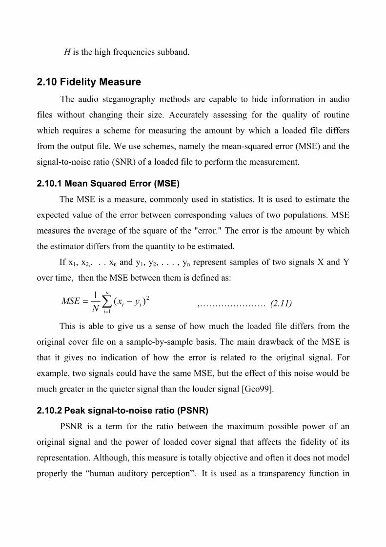
2.10 Fidelity Measure The audio steganography methods are capable to hide information in audio
files without changing their size. Accurately assessing for the quality of routine
which requires a scheme for measuring the amount by which a loaded file differs
from the output file. We use schemes, namely the mean-squared error (MSE) and the
signal-to-noise ratio (SNR) of a loaded file to perform the measurement.
2.10.1 Mean Squared Error (MSE) The MSE is a measure, commonly used in statistics. It is used to estimate the
expected value of the error between corresponding values of two populations. MSE
measures the average of the square of the "error." The error is the amount by which
the estimator differs from the quantity to be estimated.
If x1, x2,. . . xn and y1, y2, . . . , yn represent samples of two signals X and Y
over time, then the MSE between them is defined as:
∑=
−=n
iii yx
NMSE
1
2)(1 ,…………………. (2.11)
This is able to give us a sense of how much the loaded file differs from the
original cover file on a sample-by-sample basis. The main drawback of the MSE is
that it gives no indication of how the error is related to the original signal. For
example, two signals could have the same MSE, but the effect of this noise would be
much greater in the quieter signal than the louder signal [Geo99].
2.10.2 Peak signal-to-noise ratio (PSNR) PSNR is a term for the ratio between the maximum possible power of an
original signal and the power of loaded cover signal that affects the fidelity of its
representation. Although, this measure is totally objective and often it does not model
properly the “human auditory perception”. It is used as a transparency function in
Audio environment. Also, it is used as a measure of quality of reconstruction in
audio.
Because many signals have a very wide dynamic range, PSNR is usually
expressed in terms of the logarithmic scale. It is most easily defined via the mean
squared error (MSE):
⎟⎟⎠
⎞⎜⎜⎝
⎛=
MSEMax
LogPSNR i2
1010 ,………….………………… (2.12)
Where the Max is the maximum possible value of the audio samples [Jor07].
2.10.3 Signal to Noise Ratio (SNR) Signal to Noise Ratio often abbreviated SNR or S/N, it provides a measure of
noise which takes into account the strength of the original signal. If X is the cover
file and Y is the stego file, we define X to be the signal and X − Y to be the noise.
Now the SNR is defined by
error
signal
pp
SNR = ,…………………………… (2.13)
Where Psignal and Perror represent the power of the signal (X) and the noise (X −
Y), respectively.
The power of a signal is defined as the average squared amplitude of the signal
over all time. If the signal is represented as discrete samples
x1, x2, . . .,xn, the analogous definition of power is
∑=
=n
iixkp
1
2 ,..………………………….. (2.14)
Where k is a constant. This gives us an approximation of the SNR as
2222
211
222
21
...
...
nn
n
yxyxyx
xxxSNR
−++−+−
+++= ,………………… (2.15)
As we mentioned earlier, this has the advantage of giving a sense of how
prominent the error is when listening to the loaded file. The SNR is also well studied

in acoustics, and the systems which degrade audio quality often rate their
performance in terms of a signal-to-noise ratio [Jor07].


Chapter Three
System Development
3.1 Introduction The purpose of this project is to develop a hybrid system using two type of
transform for hiding binary data in the audio. In the design phase of the proposed
system the following two basic requirements have been taken into consideration: the
first one is the perceptual transparency, and the second is the high embedding
capacity. This first requirement is important to make cover object and stego cover
object perceptually indiscernible, while the second is to insure high hiding gain.
In established transform based hiding system both wavelet and DCT
transforms have been utilized, in a hybrid way, to get better hiding rate with low
perceptual changes in cover media.
The above mentioned idea of using transformation in the proposed system is
due to the results of previous published works which indicated that hiding in
frequency domain is more effective than hiding in time domain, due to the
compactness attributes of some transforms.
3.2 Audio Files Today, many types of audio file are available, such as Windows Audio Visual
(WAV), Windows Media Audio (WMA), and MPEG (MP3). The type used in this
study is WAV file format of type PCM, because it is uncompressed audio format,
which gives more flexibility for data hiding.
A stego object (WAV file) with high sampling rate and sampling resolution
may draw suspicion, because of its large size, especially if its subjective quality is not
high. Usually, it is easy to hide more secret data in the high quality audio data (for
example, the use of least significant bit encoding to embed one bit in each sample,

consist of 16 bits, sample has less effect on the stego object than adding one bit in a
sample consist of 8 bits). In the proposed system the wave files, with 8-bit samples
resolution, are used as cover media for hosting the secret data.
3.3 The Overall System Module The proposed system consists of two modules: Hiding module and Extraction
module. The hiding module is used to hide the secret massage in cover audio file, and
the extraction module is used to retrieve the secret message from stego-cover audio
file.
3.3.1 Hiding Module The block diagram of hiding module is shown in figure (3.1); it consists of the
following seven main parts:
• Load audio file (cover and secret)
• Voiced /Unvoiced segmentation
• Transformation
• Quantization/ Dequantization
• Secret data embedding
• Inverse transform
• Reconstruction of stego cover file. Each part of this module is illustrated, separately in the following subsections.
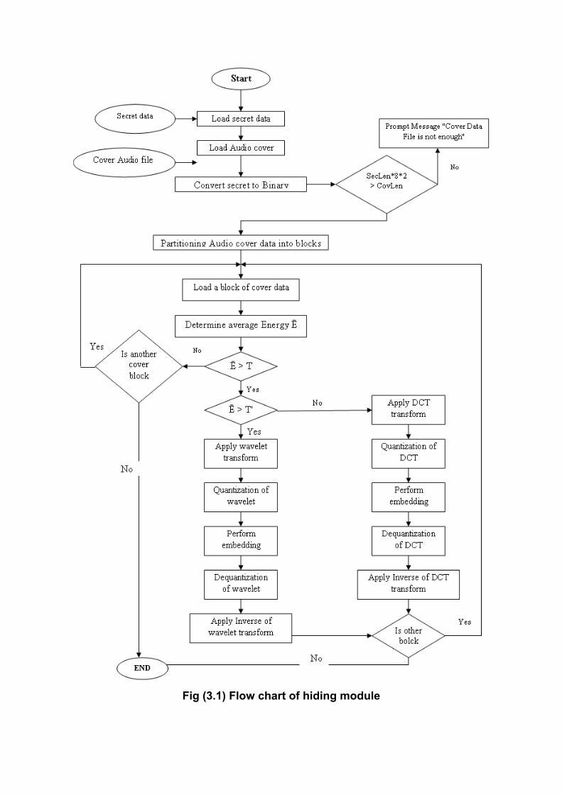
Fig (3.1) Flow chart of hiding module

3.3.1.1 Input Audio File
The cover audio file used in the proposed system is of type WAV (Windows
Audio Visual) with PCM format. Opening the audio (.wav) file need a good
knowledge about WAV header format. The WAV file starts out with a header contain
main chunk (called RIFF chunk), followed by a sequence of data chunks. A WAV
file often contains single "WAVE" chunk, which consists of two subchunks, a format
(fmt), subchunk and the (data) subchunk. The first subchunk holds the file format
information, while the second subchunk holds the audio_data samples. A detailed
description of the WAV file format is presented in appendix (A). The wave data is
stored as one channel (called mono), or as two channels (called stereo).
The audio samples resolution (i.e, number of bits per sample) is either 8 bits
(ranging from 0 to 255), or 16 bits (ranging from -32768 to 32768). This may cause
confusion when dealing with both kinds of sample resolution, because to handle both
cases two structures for the system must be established, the first one to handle the 8-
bits samples, and the second to handle the 16-bits samples. To avoid this confusion
and to unify the way of handling both cases the range of the 16-bits sample was
remapped to be between 0 and 255 (i.e., 8-bits resolution). Therefore, the value of
each sample was represented by 8-bits (whatever its original sample resolution is 8 or
16 bits), in this case, an array of byte type was originated to represent the audio cover
data. Figure (3.2) shows the block diagram of the process of loading a cover WAV
file.

Fig (3.2) The flowchart of "Loading wave file" stage
3.3.1.2 Voiced / Unvoiced Segmentation Sound consists of pressure waves which have a wide variety of waveforms,
these waveforms can be broadly categorized into voiced and unvoiced sound.
The embedding mechanism in the proposed system is hiding secret data in the
voice segments, only, of the cover. So, the audio cover data is partitioned into non-
overlapped blocks, and the hiding process will be applied on the voiced blocks only.
To recognize the voiced from unvoiced block the average power of each block is
compared with a predefine threshold value (T), to decide if the block is voiced or
unvoiced.
Start Get “RIFF” String (4 byte)
Get the size remaining data in the file (4 byte)
Get “WAVE” string (4 byte)
Get “fmt” string (4 byte)
Get fmt chunk size (4 byte)
Get fmt chunk (usually 16
Is the audio file have the Following
parameter: PCM, 8 bit, Mono
Get chunk name (4 byte)
Yes
No
Send message "It’s not (PCM , 8 bit, mono)
File"
is the chunk Name= “data”
Yes No
Get data size (4 byte)
Get the chunk data
End
Get chunk size (4 byte)
Get the chunk name

The adopted way to measure the power of the voice is based on calculating the
average of the square of samples values of each block and then this average is
compared with a threshold value (T); if it is below threshold value then the block is
considered unvoiced block, while if it is equal or above threshold then the block is
considered as voiced block. Algorithm (3.1) lists the steps of the voiced/unvoiced
segmentation process.
Also, in this stage the power of voiced block where tested to be sure its value is
not very close to threshold value (T), because if it is close to (T) then the sample
values of the block should be adjusted to make its power value is far enough from the
value (T). This additional step is taken as precaution step to avoid the occurrence of
the case "the power of the voiced block after embedding secret data may lowered and
its new value become less than T''. The occurrence of such case will cause a problem
in the extraction phase, because the extraction module will consider such hosting
blocks as unvoiced blocks, and consequently a part of secret binary data will be lost.
Algorithm (3.1) Voiced/ Unvoiced segmentation
Goal: determine if each block is Voiced or Unvoiced. Input: Wv (0 to No. of Samples -1) //array contains audio file data PowThr1 // first threshold value Block Length // the size of each block Output: Each block of Wv vector is categorized either as Voiced or Unvoiced Step1: "Define the Eps1, Eps2 value Set Eps1 PowThr1 * 0.1 Set Eps2 PowThr2 * 0.02 Step2:" Compute the Power of each block and compare it with PowThr1 value No.Block No.Samples / Block Length For i Do {where 0 ≤ i < No.Blocks} Offset i * Block Length Pow 0 For j Do { where 0 ≤ j < Block Length} Pow Pow + Wv (Offset+j)^2 End For { j } Pow Pow / Block Length If Pow ≤ Pow Thr1 then " Block is considered as unvoiced

Else " Block is considered as voiced "Check if it near threshold value then adjusts the block samples If Pow – PowThr1 ≤ EPS1 then For j Do { 0 ≤ j < Block Length} Wv(Offset + j) Wv(Offset + j) +1.1 EndFor { j } End If End If End For { i }
3.3.1.3 Transformation The basic step in the proposed system is the transformation of audio data from
time domain to frequency (or scale domain) using either DCT or Wavelet transform.
The input to transformation stage will be the voiced blocks, exclusively, of the cover
audio data. To decide whether cosine or wavelet transform is applied on the voiced
blocks, a second thresholding criteria is used; the threshold value (T') of this criteria
should be higher than the first threshold (T). According to this thresholding criteria
the block is send to cosine transform if its average power is less than the second
threshold value, otherwise it is send to wavelet transform. The usage of this criteria is
based on the fact that "at the signal parts which shows high variations the
performance of wavelet transform is better than DCT, and vice versa.
Algorithm (3.2) shows the steps taken to decide whether the voiced block is
transformed using DCT or wavelet, according to power value of the block. Also, in
this algorithm the voiced block whose power value is very close to threshold (T'), are
adjusted to ensure that its new power value is not close to (T').
In the following subsections the implemented steps to conduct DCT and
Wavelet transform are illustrated.
Algorithm (3.2) Choosing the transform type
Goal: to decide where the voiced block is DCT or Wavelet transform Input: Wav (0 ... BlockLength-1)// a voiced block PowThr2// a threshold value
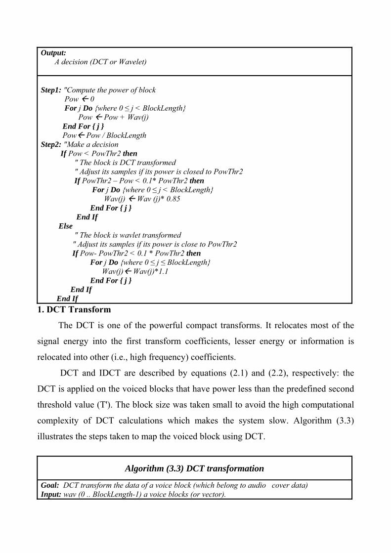
Output: A decision (DCT or Wavelet) Step1: "Compute the power of block Pow 0 For j Do {where 0 ≤ j < BlockLength} Pow Pow + Wav(j) End For { j } Pow Pow / BlockLength Step2: "Make a decision If Pow < PowThr2 then " The block is DCT transformed " Adjust its samples if its power is closed to PowThr2 If PowThr2 – Pow < 0.1* PowThr2 then For j Do {where 0 ≤ j < BlockLength} Wav(j) Wav (j)* 0.85 End For { j } End If Else " The block is wavlet transformed " Adjust its samples if its power is close to PowThr2 If Pow- PowThr2 < 0.1 * PowThr2 then For j Do {where 0 ≤ j ≤ BlockLength} Wav(j) Wav(j)*1.1 End For { j } End If End If
1. DCT Transform
The DCT is one of the powerful compact transforms. It relocates most of the
signal energy into the first transform coefficients, lesser energy or information is
relocated into other (i.e., high frequency) coefficients.
DCT and IDCT are described by equations (2.1) and (2.2), respectively: the
DCT is applied on the voiced blocks that have power less than the predefined second
threshold value (T'). The block size was taken small to avoid the high computational
complexity of DCT calculations which makes the system slow. Algorithm (3.3)
illustrates the steps taken to map the voiced block using DCT.
Algorithm (3.3) DCT transformation
Goal: DCT transform the data of a voice block (which belong to audio cover data) Input: wav (0 .. BlockLength-1) a voice blocks (or vector).

BlkLen // length of block. Output: tWv // a vector contain the embedding data. Step1:"Initialization to the parameters of DCT Set limit (Lm) blklen-1 Set Sm 0 Set BlkLn4 4 * BlikLen For j Do {where 0 ≤ j ≤ BlkLn4 -1} Cn(j)= cos(π *j /(BlkLen*2)) End For { j } Set Fac1 sqr (1/BlkLen) Set Fac2 sqr(2/BlkLen) Step2:
1. For I Do {where 0<=i<=Lm} Set Sm Sm + wav(I) Set tWv(0) Fac1 * Sm
End For { I } 2. For u Do {where 1<=u<= Lm}
Set Sm 0, Set k u, Set M (2* u) For I Do {where 0 ≤ I ≤ Lm} Set Sm Sm + Wav(I) * Cn(k) Set k k + M If k >= BlkLn4 Then k = k - BlkLn4 End For {I}
Set tWv (u) Sm* Fac2 End For { u } Step3: Save the tWv vector Step4: Return the tWv vector
2. Wavelet Transform
The input data to the wavelet transform are the samples of the cover voiced
blocks; these samples are considered as waveform representation in time domain. The
output is considered as representation in scale-shift domain. The blocks whose
average energy is above the second threshold value is sent to wavelet transform.
In this work, the Haar wavelet is used to transform the data by calculating the
sums and differences between two adjacent elements. The equations of forward Haar
wavelet transform are described by equations (2.4 – 2.7) mentioned in section (2.9).
Algorithm (3.4) presents the implemented steps of forward Haar wavelet
transform.

Algorithm (3.4) of Haar Wavelet Transform
Goal: Apply Haar wavelet transform on a voice block extracted from Audio cover data. Input: wav (0 ..BlkLen) // a block of voice block. BlkLen // length of the block. Output: tWv // a vector contains the transform coefficients.
Step1:"Determine some involved parameters. Set Low high block length \2 Set Low high M low high – 1 Step2: For I Do {where 0≤ I ≤ Limit high M} Set i1 = i + I Set i2= i1+1 Set tWv(I) Wav(i1) + Wav(i2) Set tWv (I+ Limit high) Wav(i1) – Wav(i2) End For { I } Step3: Return the tWv vector.
3.3.1.4 Quantization/ Dequantization Quantization is a process comes after the transform; the type used here is the
uniform scalar quantization, where each sample is treated individually. The gaps
made between the quantized values of the transform coefficients should be enough to
carry the added values of secret data. The adopted uniform scalar quantization was
applied using the following equation:
( )⎟⎟⎠
⎞⎜⎜⎝
⎛×=
QitWvroundQiQwv )( ,……………………….. (3.1)
Where:
tWv (i) : is the original value of ith transform coefficient.
Q : is the quantization step.
Qwv (i) : is the corresponding ith quantized coefficient.
i= 1, 2, …, N-1
In both types of transforms (i.e., DCT and wavelet), the left half of their
coefficients was chosen as a host media for embedding secret data. For DCT the
coefficients of the left half represent the high frequency coefficients, and for wavelet
transform the left half coefficients holds the detail coefficients. The reason behind

choose high frequency coefficients is relevant with the fact that the auditory system,
normally, shows weak sensitivity in high frequency regions. Since the hosting of
secret data will be in upper half part of transform coefficients; then only the
coefficients belong to this half will be quantized. Algorithm (3.5) shows the
implemented quantization process.
Algorithm (3.5) Quantization of transform Coefficients
Goal: Quantized the cover file for embedded data Input: tWv // a vector represent transform coefficient Q // is the quantization step BlkLen // is the number of transform coefficients Output: Qwv // a vector represent data after Quantization. Step1: "Determine the boundary of upper half part Lh = BlkLen/2 Step2: For i Do {where Lh ≤ i <BlkLen} Set Qwv (i) round (tWv (i) /Q (i))* Q End For { i } Step3: Return Quantized vector (Qwv)
3.3.1.5 Data Embedding It is an important stage in hiding module. In this stage, the quantized
coefficients are used as stego cover media to hold the secret data. The adopted
embedding technique in the proposed system is "modulation", where the value of host
coefficients are changed either by subtracting or adding a specific value (δ). The
addition or subtraction will depend on the value of secret bit, such that:
tstg(i) = ⎪⎩
⎪⎨
⎧
=≥+=≥−
<
12/)(02/)(
2/)(
SandNiifitWvSandNiifitWv
NiifitWv
δδ …………(3.2)
Where,
tstg(i) is the ith transform coefficient after embedding process.

tWv(i) is the ith quantized value of transform coefficient.
δ is the modulation step.
N is the length of voiced block.
S is the value of the embedded secret bit.
Algorithm (3.6) lists the implemented step of embedding secret bit in on voice
cover block.
Algorithm (3.6) Embedding Process
Goal: embedding the Secret data in cover audio file. Input: Qwv // a vector holds the quantized coefficients of cover voice block Sec //a vector holds the binary sequence of the secret massage Blklen //number represent the length of block. V // pointer refers to the position of secret bits waiting for embedding. Output: tWv //a vector represent the cover with secret massage Step1: "Initialization for hiding process parameter Set Lh block length \ 2 Set Delta = (1 / 3) * Quantized step Step2:For i Do {where Lh ≤ i < BlkLen} If Sec (v) = 0 Then tWv (i) Quantized value(i) - Delta Else tWv (i) Quantized value (i) + Delta End If End For { i } Step3: Return tWv vector which represent the audio cover holding the embedded secret data.
It is clear from equation (3.2), and also from algorithm (3.6), the embedding
process is based on dealing with secret data as a sequence of binary digits {0, 1}.
And, the value of each secret bit (binary digits), is used to decide what kind of
modulation (i.e., addition or subtraction) is done on each transform coefficients used
as host media.
The secret message is converted from an array of characters (or bytes) to an
array of bits. Algorithm (3.7) shows the applied steps to make the conversion of
secret message from a string to an array of bits.
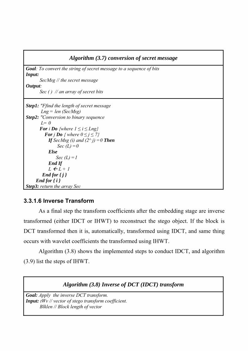
Algorithm (3.7) conversion of secret message
Goal: To convert the string of secret message to a sequence of bits Input: SecMsg // the secret message Output: Sec ( ) // an array of secret bits Step1: "Ffind the length of secret message Lng = len (SecMsg) Step2: "Conversion to binary sequence L= 0 For i Do {where 1 ≤ i ≤ Lng} For j Do { where 0 ≤ j ≤ 7} If SecMsg (i) and (2^ j) =0 Then Sec (L) =0 Else Sec (L) =1 End If L L + 1 End for { j } End for { i } Step3: return the array Sec
3.3.1.6 Inverse Transform As a final step the transform coefficients after the embedding stage are inverse
transformed (either IDCT or IHWT) to reconstruct the stego object. If the block is
DCT transformed then it is, automatically, transformed using IDCT, and same thing
occurs with wavelet coefficients the transformed using IHWT.
Algorithm (3.8) shows the implemented steps to conduct IDCT, and algorithm
(3.9) list the steps of IHWT.
Algorithm (3.8) Inverse of DCT (IDCT) transform
Goal: Apply the inverse DCT transform. Input: tWv // vector of stego transform coefficient.
Blklen // Block length of vector

Output: Stg ( ) // vector of stego_cover data after applying IDCT Step1: "Determine of some involved parameters
Set Lm block length - 1 Set Fac sqr (1/ block length) Fac C= sqr(2/BlkLen) BlkLn4 = 4 * BlkLen Cn (0) = Fac C For u Do {where 0 ≤ u < BlkLn4} Cn (u)= Fac C * cos (π* 4/ (2*BlkLen)) End for {u} Set m 1 Set T tWv(0) * Fac
Step2: For i Do {where 0 ≤ i ≤ Lm} Set Sum T Set K M For u Do {where 1≤ u ≤ Lm}
Set Sum Sum+ Cn(k) * tWv (u) Increment k by m If k ≥ BlkLn4 Then decrement k by BlkLn4 End For {u} Set Stg (i) Sum End For {i}
Step3:Return the reconstructed vector {rWv}
Algorithm (3.9) Inverse of Haar Wavelet transform
Goal: Apply the inverse Haar Wavlet transform Input:
tWv // vector of stego transform coefficients Blklen // block length
Output: Stg ( ) // vector represent the stego_cover data after applying Inverse of
Wavelet transform.
Step1: "Determination of the involved parameter
Set Lh block length \ 2 Step2: For i Do {where 0 ≤ i < Lh}
Set Ij 2 * i Set Ip I + Lh
Set rWv (Ij) = (tWv (i) + tWv (Ip))/2 Set rWv (Ij+1)= (tWv (i) – tWv (Ip))/2
End For Step3: Return the reconstructed Wave block {rWv ()}

3.3.1.7 Reconstruction of Stego Cover File This step is performed to save the stego-object data into an audio file. The
chosen audio format (.wav) format with 8-bit sample resolution, PCM-coding, single
channel (mono). At first the header of wave file is constructed and saved in the file,
then the stego-audio data are saved.
3.3.2 Extraction Module This module is used to retrieve the original secret binary message from the
stego audio data; it works in reverse way to that of hiding module. The extraction
module consists of the following stages:
• Loading stego audio file
• Voiced \Unvoiced segmentation
• Transformation
• Extracting the embedding secret data
Figure (3.3) illustrates the stages of the extraction module. The main stages of
this module are described in the following subsections:
3.3.2.1 Load Audio File The steps of loading the stego audio file are the same like the steps mentioned
in section (3.3.1.1), which load the WAV file and extract the header information and
the audio stego data.
3.3.2.2 Voiced /Unvoiced Segmentation Segmentation for voiced and unvoiced is also the same process mentioned in
section (3.3.1.2). This stage is important to determine if the block is voiced or
unvoiced. Taking into consideration that only the voiced blocks are used as host
space for hiding the secret data.
3.3.2.3 Transformation
The steps of transformation stage are similar to those followed in the
corresponding stage in hiding module (see section 3.3.1.3).
3.3.2.4 Extraction of the Embedded Data The extraction process is the inverse of embedding process, in this stage the
value of the transform coefficient is compared with its quantized value to decide
whether the embedded data is 0 or 1, such that:
If C > Q * round ⎟⎟⎠
⎞⎜⎜⎝
⎛QC then S=0 else S=1
Where,
C is the transform coefficient.
Q is the quantization step.
S is the retrieved secret bit.
Algorithm (3.9) shows the applied steps for extraction.

Fig (3.3) The extraction module
Algorithm (3.9) for Extraction Module

Goal: retrieve the embedding data from cover file. Input: tWv // vector represent the quantized transform coefficient of stego block BlkLen // number represent the block length. V // a pointer to the location of retrived secret bit in the array of secret binary array. Q // the quantization step Output: ExSec // vector represent the orginal embedded data (secret message). Step1: "Determine the start index of the upper half part of the block Lh= BlkLen /2 Step2: For i Do { where Lh ≤ i < BlkLen} Qwv Q * round (tWv (i) / Q) If qwv > tWv (i) Then ExSec(v)=1 Else ExSec (v)=0 Increment v by one End for{i} Step3: Return the Secret Message (ExSec) from the cover file.

Chapter Four
Experimental Results 4.1 Introduction In this chapter, the results of some conducted tests are presented. These tests
are performed to evaluate the performance of the proposed audio hiding methods.
Also, in this chapter the effects of the involved system parameters on its performance
behavior are explored.
4.2 Test Measures The measures used in this research work to assess the performance of the hiding
method are the followings:
A. Fidelity Measures The adopted fidelity measures are:
• Mean Absolute Error (MAE),
• Mean Square Error (MSE),
• Peak Signal to Noise Ratio (PSNR).
The definition of the above fidelity measures are given in chapter two, see
equations (2.11), (2.12), (2.13). PSNR are often measured in logarithmic scale and
the unit of this measure is called decibel (dB). These measures have been used to
represent the overall error caused in stego-cover due to embedding of secret data.
B. Hiding Rate (HR) This parameter is determined to assess the capability of the tested hiding
method to embed secret information in the cover object. Mathematically, hiding rate
is defined as equation (4.1):
1008
××
=M
SHR % ,………………………………...(4.1)

Where, S is the maximum possible number of inserted bits in the cover media.
M is the size of cover media (in bytes).
C. Ratio of Correctly Retrieved Secret Bits (ER) This parameter is determined to describe the capability of the tested hiding
method to preserve the integrity of the embedded secret data. It is defined as the ratio
of the number of correct secret bits (Sc) extracted from the stego object relative to the
total number (S) of embedded secret bits:
%100×=SS
ER c ,…………………………………(4.2)
4.3 Test Samples Some audio files have been selected as cover media to investigate the hiding
performance. Table (4.1) shows a list of the selected cover files, while table (4.2)
shows a list of files whose content used as test material for embedding.
Table (4.1) The list of Wave files used as cover media
File Name File Size Sampling Rate (KHz)
Spch1 28.2 KB 8
Sng1 46.2 KB 11
Sng2 46.5 KB 8
Music1 88 KB 11.10
Spch2 148 KB 11
Sng3 156 KB 8
Sng4 183 KB 8
Spch3 213 KB 8
Sng5 626 KB 8
All the above sound files are of WAV type, PCM format, Mono and Sample
resolution=8 bits.

Table (4.2) The list of files whose contents used as secret material
File Name File Size (KByte) File Type
SngSec 148 Wav
SpcSec 28 Wav
DocSec 55.5 DOC
ImgSec 21.1 JPG
4.4 Test Results and Discussion The performance of the proposed hiding methods was based on studying the
effects of changing the involved parameters on hiding performance measures. The
results of the various conducted tests have indicated that the type of cover audio file
has significant effect on the performance parameters (like, hiding rate, correct
retrieval bits and quality of stego cover file). Therefore, the choice of audio cover file
should be handled carefully, for example the low quality audio cover is recommended
more than the high quality audio cover because hiding in the first type of cover data
will not cause noticeable extra noise. It was noticed that the result of the tests vary
from cover file to another.
The control parameters that have significant effects on the performance
parameters are the two threshold values, DCT quantization step, Wavelet
quantization step, and the block length. In the following sub sections the effects of
the above control parameters on the system performance are classified.
4.4.1 Threshold Value (Thr) The classification decision of voiced/unvoiced blocks depends mainly on the
value of power threshold, if the energy of the audio block is higher than the first
threshold (T) then block is classified as voiced block. The second classification is
applied only on the voiced block; this classification is for deciding the type of
transform (DCT or Wavelet) should be applied on the voiced block.
Table (4.3) illustrates the effect of first threshold (T) on the performance
parameters, when T is increased the hiding rate of secret data is decreased. during this

test the values of other coding parameters were set to have their default values: T'=
8 12 (must be greater than first threshold value); QStp=3 (for both DCT and
Wavelet); Block Length=12.
Table (4.3) The effect of the first threshold value (T) on the performance of hiding method
T T" MAE MSE PSNR MAE(Sec) Ratio of correct
Retrieval bits
Hiding
Rate
1 8 0.456 1.684 45.87 0.077 92.260 5.077
2 8 0.425 1.645 45.97 0.786 92.135 4.753
3 8 0.406 1.621 46.03 0.080 91.965 4.559
4 8 0.387 1.598 46.10 0.081 91.881 4.373
5 9 0.373 1.584 46.13 0.822 91.777 4.181
6 9 0.355 1.561 46.20 0.084 91.584 3.974
7 9 0.334 1.534 46.27 0.086 91.387 3.776
8 10 0.316 1.515 46.33 0.086 91.320 3.571
9 11 0.302 1.504 46.36 0.086 91.345 3.388
10 12 0.289 1.491 46.40 0.084 91.526 3.223
Table (4.4) illustrates the effect second threshold (T') of the performance
parameters, when T' is increased the correct retrieval bits of secret data is increased.
During this test the values of other coding parameters were set to have their default
values: T=2; QStp=3 (for both DCT and Wavelet); Block Length=12. Table (4.4) The effect of the second threshold value (T') on the performance of
hiding method
T" MAE MSE PSNR MAE(Sec) Ratio of correct
Retrieval bits Hiding Rate
3 0.352 2.475 44.20 0.128 % 87.182 % 4.290
4 0.357 2.485 44.18 0.122 %87.760 % 4.290
5 0.363 2.496 44.16 0.118 %88.185 % 4.290
6 0.369 2.509 44.14 0.113 %88.676 % 4.290
8 0.376 2.524 44.11 0.106 %89.356 % 4.290

9 0.380 2.532 44.10 0.103 %89.607 % 4.290
11 0.387 2.547 44.07 0.099 %90.028 % 4.290
12 0.390 2.553 44.06 0.097 %90.199 % 4.290
14 0.399 2.575 44.02 0.094 %90.541 % 4.290
16 0.407 2.594 43.99 0.090 %90.978 % 4.290
4.4.2 Quantization Step (Q)
Quantization process provides a suitable space for hiding secret data. The main
parameter used to mange the amount of space is the quantization step (Q). In our
system there are two quantization parameters: one for Wavelet coefficients
(WaveletQnt),and the second for DCT Coefficients (DCTQnt). Any change in one of
these two parameters affects the hiding space in some voiced blocks. If the values of
Quantization steps are increased then the ratio of correct retrieval bit is increased and
the error in stego cover signal increased too. Table (4.5) presents the effect of
changing the wavelet QStp on the hiding performance parameters. The values of other
system parameters were fixed to have the following values: T=2; DCT QStp=3; T'=9;
Block Length=12.
Table (4.5) The effect of wavelet quantization step on the performance of hiding method
Wavelet
QStp MAE MSE PSNR MAE(Sec)
Ratio of correct
Retrieval bits
Hiding Rate
2 0.250 2.401 44.33 0.192 % 80.745 % 4.290
3 0.380 2.532 44.10 0.103 % 89.607 % 4.290
4 0.515 2.799 43.66 0.104 % 89.519 % 4.290
5 0.554 2.925 43.47 0.008 % 99.133 % 4.290
6 0.699 3.299 42.95 0.008 % 99.137 % 4.290
7 0.803 3.717 42.43 0.008 % 99.133 % 4.290
8 0.850 3.871 42.25 0.008 % 99.137 % 4.290

Table (4.6) presents the effect of changing the value DCT QStp on the hiding
method. The values of other system parameters were taken as follows: T=2; T'=9;
Wavelet QStp=3; Block Length=12.
Table (4.6) The effect of DCT quantization step on the performance of hiding method
DCT QStp MAE MSE PSNR MAE(Sec) Ratio of correct
Retrieval bits
Hiding Rate
2 0.348 2.476 44.19 0.124 % 87.555 % 4.290
3 0.380 2.532 44.10 0.103 % 89.607 % 4.290
4 0.411 2.607 43.97 0.097 % 90.199 % 4.290
5 0.443 2.705 43.81 0.095 % 90.424 % 4.290
6 0.472 2.813 43.64 0.095 % 90.465 % 4.290
7 0.500 2.933 43.46 0.095 % 90.465 % 4.290
8 0.529 3.075 43.25 0.095 % 90.465 % 4.290
4.4.3 Block Length
The effect of block length on the hiding performance is illustrated in table
(4.7). The number of inserted bits is increased when block length become large, but at
same time the error level is increase because number of changed samples in cover
data is increased due to embedding. The values of other coding parameters were fixed
to have the following values: T=2; T'=9; Wavelet QStp=3; DCT QStp=3.
Table (4.7) The effect of block length parameter on hiding method
Block
Length MAE MSE PSNR Secret
no. of Hidden
bits
Correct
Retrieval
Hiding
Rate
8 0.375 1.681 45.87 0.102 26020 % 89.727 %4.242
12 0.380 2.532 44.10 0.103 26316 % 89.607 %4.290
16 0.378 1.681 45.87 0.106 26560 % 89.363 %4.330
24 0.405 5.096 41.06 0.106 26904 % 89.325 %4.386
32 0.379 1.676 45.89 0.108 27056 % 90.000 %4.411

4.5 Performance Comparison In this section, the effects of using diffrent. Table (4.8) lists some of the result
obtained by using different covers and secret files. Also, the values of the involved
control parameter was taken according the pervious testes which indicates the most
suitable value for each parameter, The values of other constant parameters were taken
as follows: PowThr=2; TrnsThr=9; Wavelet QStp=3; DCT QStp=3; Block
Length=12. Table (4.8) illustrates the effect of using different covers.
Table (4.8) The effect of using different covers and secret audio data
Cover Secret MAE MSE PSNR Correct
Retrieval
Hiding
Rate
Spch1 SngSec 0.432 2.205 44.70 93.276 4.494
Spch1 SpchSec 0.432 2.205 44.70 93.258 4.494
Spch1 DocSec 0.421 2.203 44.70 91.878 4.494
Spch1 ImgSec 0.436 2.212 44.68 91.415 4.494
Sng1 SngSec 0.908 5.252 4.93 99.962 6.214
Sng1 SpchSec 0.908 5.252 40.93 99.974 6.214
Sng1 DocSec 0.554 4.385 41.71 90.518 6.214
Sng1 ImgSec 0.561 4.387 41.71 89.693 6.214
Sng2 SngSec 0.266 2.671 43.86 91.612 2.928
Sng2 SpchSec 0.266 2.671 43.86 91.639 2.928
Sng2 DocSec 0.266 2.675 43.86 90.098 2.928
Sng2 ImgSec 0.267 2.675 43.86 89.417 2.928
Music1 SngSec 0.380 2.532 44.10 89.607 4.290
Music1 SpchSec 0.384 2.537 44.09 91.187 4.290
Music1 DocSec 0.379 2.535 44.09 90.937 4.290
Music1 ImgSec 0.384 2.536 44.09 89.808 4.290
Spch2 SngSec 0.432 1.660 45.93 92.334 4.753
Spch2 SpchSec 0.430 1.660 45.93 90.843 4.753

Spch2 DocSec 0.425 1.657 45.94 90.840 4.753
Spch2 ImgSec 0.430 1.659 45.93 90.261 4.753
Sng3 SngSec 0.523 0.886 48.66 91.652 5.906
Sng3 SpchSec 0.524 0.890 48.64 90.319 5.906
Sng3 DocSec 0.520 0.886 48.66 90.370 5.906
Sng3 ImgSec 0.521 0.887 48.65 89.807 5.906
Sng4 SngSec 0.551 0.800 49.10 91.561 6.108
Sng4 SpchSec 0.551 0.800 49.10 90.466 6.108
Sng4 DocSec 0.551 0.801 49.09 90.580 6.108
Sng4 ImgSec 0.549 0.799 49.11 90.102 6.108
Spch3 SngSec 0.320 0.364 52.52 92.549 3.563
Spch3 SpchSec 0.322 0.366 52.49 91.268 3.563
Spch3 DocSec 0.318 0.365 52.51 91.064 3.563
Spch3 ImgSec 0.318 0.364 52.52 90.756 3.563
Sng5 SngSec 0.567 0.964 48.29 92.051 5.885
Sng5 SpchSec 0.564 0.959 48.31 91.784 5.885
Sng5 DocSec 0.560 0.959 48.31 92.323 5.885
Sng5 ImgSec 0.565 0.961 48.30 91.403 5.885
Table (4.9) The effect of using different transform type on different audio cover
Cover Secret Wavelet
(HR)
Wavelet
(MSE)
DCT
(HR)
DCT
(MSE)
Spch1 SngSec 4.559 2.552 4.559 2.821
Spch1 SpchSec 4.559 2.539 4.559 2.829
Spch1 DocSec 4.559 2.530 4.559 2.818
Spch1 ImgSec 4.559 2.528 4.559 2.10
Sng1 SngSec 4.290 2.470 5.201 2.729
Sng1 SpchSec 4.290 2.471 5.201 2.731
Sng1 DocSec 4.290 2.474 5.201 2.735
Sng1 ImgSec 4.290 2.479 5.201 2.740
Sng2 SngSec 3.885 1.744 2.885 1.711

Sng2 SpchSec 3.885 1.740 2.885 1.709
Sng2 DocSec 3.885 1.737 2.885 1.707
Sng2 ImgSec 3.885 1.734 2.885 1.704


Chapter Five
Conclusions and Suggestions
5.1 Introduction In this chapter, a list of conclusion remarks are presented, they derived from
the investigation of the test results shown in chapter four. Also, some suggestions for
a future work are presented; they may enhance the system efficiency.
5.2 Conclusions From the test results listed in pervious chapter the following remarks were
stimulated:
1. Using two type of transform (DCT and Wavelet) provides a flexibility to
utilize the power of more than one transform to perform hiding in audio signal
without making subjective distortion. The block may be DCT or Wavelet
transformed according to its power relative to a threshold value. The change in
threshold value will cause a change in the ratio of voiced blocks transformed
by Wavelet or DCT.
2. The use of two predefined threshold value: power threshold (T) and transform
threshold (T'), added some power to the steganography process, because it is
divided the audio cover signal blocks into different types (voiced and
unvoiced) blocks. Large threshold values increase the avoidance of unvoiced
blocks and cause an increase in the ratio of correct retrieved bits, but decreases
the hiding rate.
3. Hiding in voiced blocks is more suitable to avoid the occurrence of stick noise,
which is more probably happen when unvoiced blocks are used as host area.
4. Large quantization step provides more robust space to hide secret bits, while it
causes subjective distortion in cover audio.

5. The unvoiced data samples are one of the worst host region in the cover audio
data, because the noise can be easily noticed when it reside the silent region, so
the selection of the cover file must be done carefully. In other words the
selection of aloud audio cover with little unvoiced area in necessary to get
good hiding performance result so the use of some music audio as cover media
is most suitable for hiding since the distortion due to data embedding doesn’t
obviously sensible.
5.3 Suggestions The developed hybrid system needs some enhancements to improve its
performance and to override some of its weak aspects. Therefore, a future
development is needed, and in the following some suggestions are derived for future
relevant work:
1. Using other criteria to partition cover data into voiced or unvoiced regions.
Since the insertion of the secret data may reduce the power of block, and
convert its identity from voiced to unvoiced block. So, some efforts must spent
to prevent the occurrence of such a case, because its occurrence affects the
integrity of the extracted secret message.
2. Using other criteria to determine the most suitable transform that a block
should mapped to (i.e., which is better for a block to be transformed using
DCT or Wavelet).
3. Develop the proposed system to be used for hiding in other audio file formats
likes (MP3 and ADPCM wav file).
4. Develop a system for hiding audio in image or audio in video using the same
embedding technique that used in the proposed system.


[Ahm74] Ahmed, N., Nararajan, T., and Rao, K. R., “Discrete cosine transform”,
IEEE Transactions on Computers, pp. 90-93, Jan. 1974.
[Are00] Areepongsa, S., Kaewkamnerd, N., Syed, Y. F., and Rao, K. R., "Exploring
on steganography for low bit rate wavelet based coder in image retrieval
system", Research in Tencon Unversity, 2000.
[Aud03] Auday, A., "Fractal image compression with fasting approach", Msc. Thesis,
Dept. of Computer Science, Al-Nahrain University, Iraq, 2003
[Alf06] Alfaraj, A., "On the limits of steganography", M.Sc. thesis, Information
Security, UCL, 2006.
[Ben96] Bender, W., "Techniques for data hiding", IBM System Journal; vol .35, no.
3-4, pp. 1-10, February, 1996. http://www.research.ibm.com/journal/sj/353/sectiona/bendeaut.html#bender
[Bak03] AL Baka'a , A. T. ,"Image copyright protection using digital watermarking ",
M.Sc. Thesis, Computer Science Department, College of Science, AL-
Nahrain University, Iraq, 2003.
[Bri06] Brian, J., Yuliya, K., and Andrew, L., "Audio steganography", CDP Digital
Audio Working Group, 2006.
[Bak07] Bakshi, B., "Steganography", Reseach , Syracus University, 2007.
[Cyb87] Cyber, B., "Digital Audio Basics ", Paper, Department of Interior, National
Park Service, Edison National Historic Site, 1987.
[Cra98] Craver, S., "On public key steganography", Information Hiding: Second
International Workshop, Proceedings, vol. 1525 of lecture Notes in
Computer Science, Springer , pp 355-368, 1998.
[Cac00] Cacciguerra, S., and Ferretti, S.,"Data hiding: Steganography and copyright
marking", Paper, Department of Computer Science, Bologna University,
Italy, 2000.

[Cum04] Cummins, J., Diskin, P., Lau, S. and Parlett, R.,"Introduction to
steganography", School of Computer Science, University of Birmingham,
2004.
[Dec99] Decamro, L., "New Technologies for audio copy Protection", Electronic
Media Article, 1999.
[Dav00] Davern, P., and Scott, M., "Steganography: its history and its application to
computer based data files", Research, School of Computer Application, UK,
2000.
[Die03] Yasmeen I. Dieab., "Text in audio watermarking system", M.Sc. Thesis,
Computer Science Department, College of Science, Al-Nahrain University,
Baghdad-Iraq, 2003.
[Ett98] Ettinger, J. M., "Steganalysis and game equilibria", Information Hiding:
Second International workshop, Proceedings, vol. 1525 of Lecture Notes in
Computer Science, pp. 319-330, Springer, 1998.
[Fab99] Fabien, A., Petitcolas, P., Ross, J. A., and Markus G. K., "Information
hiding-a survey", IEEE special issue on protection of multimedia content,
87(7):1062{1078, July 1999.
[Geo99] George, C., and Lehmann, E.L., "Theory of point estimation", Springer,
1999.
[Gar01] Gary C. K., "Steganography: hiding data within data", Paper in Windows &
.NET Magazine, September, 2001.
[Hai07] Haibin, H., "Lossless audio coding for MPEG-4", Research, Computer
Science and Statistics Dissertation, University of Joensun 2007.
[Joh98] Johnson, N. F., jajodia, S., "Steganalysis of images created using current
steganography software", information hiding Second International
Workshop, Proceedings, vol. 1525 of Lecture Note in computer science, pp
273-289, Springer, 1998.

[Joh01] Johnson, N. F., Duric, Z., and Jajodia, S., "Information hiding:
steganography and watermarking – attacks and countermeasures",
research, Kluwer Academic Publishers, 2001.
[Jia03] Jianyun , X., Andrew H. S., Peipei, S. and Qingzhong, L., "Text
steganography using wavelet transform", M.Sc. thesis, Department of
Computer Science, New Maxico Tech, Socorro, NM87801, USA, 2003.
[Jor07] Jordi, H., "Information hiding and steganography", Conference on
Cryptology and Digital Content Security, study on Information hiding and
Multimedia, Universitat Oberta de Catalunya, May 15, 2007.
[Kie98] Kientzle, T., "Programmers guide to sound", Addison Wesley Developers
Press, 1998.
[Kat00] Katezbeisser, S. P., and Fabian, A., "Information hiding techniques for
steganography and digital watermarking", Artech House Inc., Norwood
University, 2000.
[Kes01] Kessler, G. C.," Steganography: hiding data within data", Windows & .net
Magazine, September 2001.
[Kaw06] AL Kawaz , H. M., "Low rate hiding in audio data using phase domain ",
M.Sc. thesis, Computer Science Department, College of Science, AL-
Nahrain University, Baghdad, Iraq, 2006.
[Maj04] Majeed, M. N, "Sound hiding and extraction using DCT", M.Sc. Thesis,
Computer Science Department, College of Science, Al-Nahrain University,
Baghdad-Iraq, 2004.
[Moh04] Mohammad, N.M., "Sound hiding and extraction using DCT", M.Sc.
Thesis, Computer Science Department, College of Science, AL- Nahrain
University, Baghdad, Iraq, 2004.
[Rob96] Robi, P., "The wavelet tutorial", research, 136 Rowan Hall, Dept. of
Electrical and Computer Engineering, Rowan University, 1996..
[Ras02] Rastislav, H., Peter, F., Dušan, L., "Steganography based on DWT
transform", Department of Electronics and Multimedia

Telecommunications, paper, Technical University of Košice, Slovak
Republic, 2002.
[Sel99] Sellars, D., "Techniques for data hiding", In IBM Systems Journal, Vol. 35,
Nos. 3-4, pages 313-336, February 1999.
[Sib04] Si, B., "Introduction to steganography", Athabasca University, COMP607
Project, 25 July 2004.
[Xiu07] Xiuhui G., Renpu J., Hao T., Jiazhen W., "Research on information
hiding", Research, Hebei University of Economics and Business/Ordnance
Engineering College, 2007.
[Yan01] Yang, Y., "Digital watermarking technologies", Computer Science,
Dalhousie University, 2001.
[Ziy02] AL-Ta'l, Z., "Development of new cover audio cryptographic models", Ph.D
Thesis, University of Technology, July 2002.

Appendix A
The WAV file Format
The RIFF Header Chunk
Offset Size (Byte) Field name Content Description
0 4 Chunk ID Contain the string "RIFF" in ASCII
4 4 Chunk Size The size of WAV file in bytes minus 8 bytes (4
byte to Chunk ID and 4 byte to Chunk size)
8 4 Format Contain the string "WAVE"
The fmt Sub-Chunk
Offset Size (Byte) Field name Content Description
12 4 Sub-Chunk1 ID Contain the string "fmt"
16 4 Sub-chunk1 Size
This number describes the rest sub-chunk data:
audio format (2 bytes), number of channels (2
bytes), sample rate (4 bytes), bytes/sec (4 bytes),
block alignment (2 byte), bits/sample (2bytes).
This, usually, has length (16) bytes.
20 2 Audio Format Type of WAVE format. (1) mean PCM other than
1 indicates some form of compression.
22 2 No. of Channels Channels: Mono=1, Stereo=2, etc.
24 4 Sample Rate Sample per second.
e.g., 8000,22000,44100, etc.
28 4 Byte Rate Byte per second = Sample Rate × Channel
Numbers × BitsPerSample/8
32 2 Block Align The number of bytes for one sample including all
channels. It is equal to number of channels ×
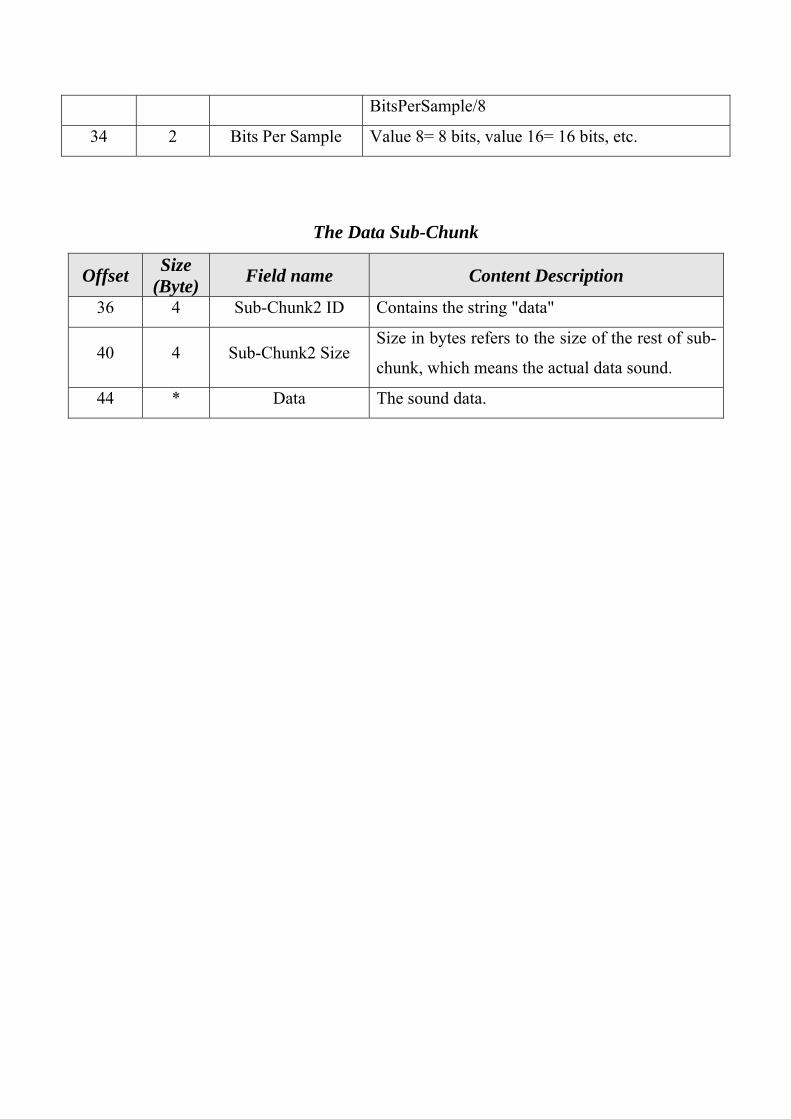
BitsPerSample/8
34 2 Bits Per Sample Value 8= 8 bits, value 16= 16 bits, etc.
The Data Sub-Chunk
Offset Size (Byte) Field name Content Description
36 4 Sub-Chunk2 ID Contains the string "data"
40 4 Sub-Chunk2 Size Size in bytes refers to the size of the rest of sub-
chunk, which means the actual data sound.
44 * Data The sound data.
Related Documents

![Performance Comparison of DCT and Walsh Transforms for ... · contents thereby degrading the host image. Discrete Wavelet Transform[2],[8],[13] and Discrete Cosine Transform[3],[8],[13]](https://static.cupdf.com/doc/110x72/5f1798a13bf2a454811b5cd6/performance-comparison-of-dct-and-walsh-transforms-for-contents-thereby-degrading.jpg)