A P P L I C A T I O N S G U I D E Audible/ Visible Appliance Reference Guide

Welcome message from author
This document is posted to help you gain knowledge. Please leave a comment to let me know what you think about it! Share it to your friends and learn new things together.
Transcript

A P P L I C A T I O N S G U I D E
Audible/VisibleAppliance
Reference Guide
1
Introduction: The Need for an Audible/Visible Compliance Reference Guide
The installation and performance requirements for audible/visible appliances in general are addressed in three documents: 1. ADAAG, ‘Americans with Disabilities Act Accessibility Guidelines’, the Federal Civil Rights Law prohibiting discrimination on the basis of disability, 2. ANSI 117.1–2003 ‘Accessible and Usable Buildings and Facilities’, a standard on accessibility designed to be adopted as part of a building code, and 3. NFPA 72, the National Fire Alarm Code, 2007 edition, an installation standard for fire alarm systems normally not adopted directly into law, but referenced in a building code as the standard to be followed.
Currently, the NFPA 72 and IFC 2006 Edition/ANSI–2003 have been harmonized. Chapter 7 of ANSI 117.1-2003 (Communication and Element Features) section 702.1 “Accessible audible and visual alarms and notification appliances shall be installed in accordance with NFPA 72 listed in Section 105.2.2, be powered by a commercial light and power source, be permanently connected to the wiring of the premises electric system, and be permanently installed.” Therefore, the standards are consistent in regards to the type, visual intensity, and amount of visual alarm notification appliances, i.e. strobes, to use within a given space, as well as the mounting and placement of such appliances. The current ADAAG, however, has not been updated since its initial publication in 1991 and does not reflect recent technological advances within the industry. As such, the current version of the ADAAG is not harmonized with the NFPA72, 2007 edition, and IFC 2006 Edition/ANSI–2003. As a result, the ADAAG provides differing guidelines as regards strobe selection from those of the two harmonized codes.
On November 16, 1999, the Access Board, an independent Federal agency devoted to accessibility for people with disabilities, published a proposed rule in the Federal Register to change the ADA Accessibility Guidelines (ADAAG). These updated guidelines, if adopted by the Department of Justice after a period of public review and commentary, would be the first comprehensive update of the ADAAG since its initial publication in July 1991. However, until adopted, the current (1991) version of the ADAAG remains in effect.
System Sensor has prepared this Reference Guide in an effort to help promote understanding and awareness of the issues that affect specifying engi-neers, installers, and the enforcement authorities. We hope to increase the probability of proper installation and reduce the possibility of misapplication of audible/visible appliances in the commercial market place.
A P P L I C A T I O N S G U I D E
Audible/Visible ApplianceReference Guide
Contents
Introduction ................................................................................................................................................................................................1
What Is Required To Comply? .................................................................................................................................................................2
What Is The ADAAG? ...............................................................................................................................................................................2
What Is The Coverage and Enforcement of the ADA? .......................................................................................................................3
What Is “Public Mode” vs. “Private Mode” Operation? ...................................................................................................................3
Visible Signaling Appliance Requirements ..........................................................................................................................................4
Where Should Strobes Be Located? .....................................................................................................................................................5
How Many Strobes Should Be Used? ...................................................................................................................................................6
Ceiling-Mounted Visual Alarm Appliances and the ADA .............................................................................................................. 7-8
What About Photosensitive Epilepsy and Strobe Flash Rates? .......................................................................................................8
Audibility Requirements ..................................................................................................................................................................... 9-10
Voltage Drop Calculations .....................................................................................................................................................................10
Power Supply Considerations ..............................................................................................................................................................11
What Is Meant By Polar Light Distribution? .......................................................................................................................................11
Glossary ....................................................................................................................................................................................................12

The ADAAG is the official standard for accessible design under Title III of the ADA. It covers only new construction
and alterations made to the fire alarm system undertaken by facilities covered by the ADA. The ADAAG was written by the Access Board. The Access Board, in one of its infor-mation bulletins, states: “Because the ADA is civil rights law, compliance with and enforcement of its implementing reg-ulations are not overseen by a local building code official, but are exercised through private suit or by specified federal agencies when discrimination—or the probability of discrim-ination on the basis of disability—is alleged.”
A few states have adopted ADAAG as their accessibility code and implement its provisions through state and local building code officials in the same way as other applicable build-
ing regulations are applied, reviewed and enforced. Many jurisdictions are expected to submit their building codes and/or standards for review by the Department of Justice. Standards that meet or exceed the minimum accessibility requirements of the ADA will be certified. The model codes, including ANSI 117.1, have sought to coordinate accessibility provisions through informal review and technical assistance from DOJ.
ADA/ADAAG compliance does not relieve the designer from complying with the provisions of a state or local access code.
“Where such a code contains more stringent requirements, they must be incorporated. Conversely, adoption of ADAAG or certification of the equivalence of a state/local code will not relieve covered entities of their responsibilities to meet the accessibility standards imposed by the ADA.”
A U D I B L E / V I S I B L E A P P L I A N C E R E F E R E N C E G U I D E
2
Due to differing codes and standards, compliance entails meeting all of the
ADA requirements or providing “equivalent facilitation” as well as adhering to NFPA 72, installation, and UL 1971, per-formance standards. It is always prudent to consult with your Authority Having Jurisdiction (AHJ) and/or local fire marshal to ensure that you are meeting all applicable codes and standards. The diagram to the right illustrates the five steps to compliance.
Equivalent FacilitationCurrently, equivalent facilitation is stated as follows per NFPA: “Departures from particular technical and scop-ing requirements of this guideline by the use of other designs and technologies are permitted where the alternative designs and technologies used will pro-vide substantially equivalent or greater access to and usability of the facility.”
The Access Board, also known as the Architectural and Transportation Barriers Compliance Board, advises that “...by varying lamp intensity and spacing, systems designers can tailor an installation to the physical conditions of the space being served.” However, the Access Board goes on to caution that it is impossible to provide specific guidance for the design of non-standard installations based upon the photo-metry calculations necessary to demonstrate equivalent facilitation.
What Is The ADAAG?
What Is RequiredTo Comply?
In the proposed Americans with Disabilities Act Accessibility Guideline (ADAAG), Equivalent Facilitation verbiage has been simplified and is more user friendly. Specifically,
“Nothing in these guidelines is intended to prevent the use of designs or technologies as alternatives to those prescribed in this document, provided they provide equivalent or supe-rior accessibility and usability.”
• Corridor• Sleeping • Non-Sleeping
• UL 1971 (Public Mode)• UL 1638 (Private Mode)
• Public• Private
• ADA • Exclusions to ADA Coverage
• NFPA 72 Chapter 4• ANSI 117.1 Model Building Code• State Local Code• Local Authority Having Jurisdiction (AHJ)
Follow Installation StandardComply With Federal Law
Determine
Performance StandardDetermine Area
To Be ProtectedSelect Operating Mode*
5 Steps to Compliance
Exclusions to ADA Coverage:• Individual employee offices and work stations.
Arrangements should be made, however, to comply with the provisions of Title I, which addresses provid-ing reasonable accommodations; e.g., a visible signal for an employee who is deaf or hard of hearing.
• Religiousentitiesandprivateclubs.
• Strictlyresidentialprivateapartmentsandhomes.
• FederalbuildingscoveredbytheArchitecturalBarriers
Act of 1968 [ABA] and, currently, by the Uniform Federal Accessibility Standards [UFAS]; a corporation wholly owned by the government of the U.S., or an Indian tribe.
• Multi-familyresidentialfacilities(generallycoveredbythe Fair Housing Amendments Act of 1988 [FHAA] and its related regulations and standards).
“Private mode” applications are those where a signal is known to be in place and where someone is trained to take additional action upon
notification from the alarm signal. Examples include control rooms, nurses’ stations and guard desks. These emergency signaling applications may not have to meet ADA require-ments and may be satisfied through installation of UL 1638 appliances.
“Public mode” operation includes audible or visible signal-ing to occupants or inhabitants of the area protected by the fire alarm system.
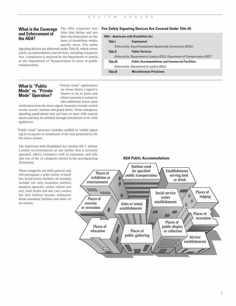
The Americans with Disabilities Act, Section 301-7, defines a public accommodation as any facility that is privately operated, affects commerce with its operation, and falls into one of the 12 categories shown in the accompanying illustration.
These categories are fairly general and will encompass a wide variety of facili-ties. Social service facilities, for example, include not only homeless shelters, adoption agencies, senior citizen cen-ters, food banks and day care centers, but also halfway houses, substance abuse treatment facilities and other cri-sis centers.
S Y S T E M S E N S O R
3
The ADA comprises four titles that define and pro-hibit discrimination on the basis of disabilities within specific areas. Fire safety
signaling devices are addressed under Title III, which covers public accommodations and services, including transporta-tion. Compliance is enforced by the Department of Justice, or the Department of Transportation in areas of public transportation.
What is the Coverage and Enforcement of the ADA?
What Is “Public Mode” vs. “Private Mode” Operation?
Places ofpublic gathering Service
establishments
Sales or rentalestablishments
Places of lodging
Places ofeducation
Places of recreation
Places of public display or collection
Social servicecenter
establishments Places of
exerciseor recreation
Places of exhibition or
entertainment
Establishments serving food
or drink
Stations usedfor specified
public transportation
ADA Public Accommodations
ADA – Americans with Disabilities Act
Title I Employment
Enforced by: Equal Employment Opportunity Commission (EEOC)
Title II Public Services
Enforced by: Department of Justice (DOJ), Department of Transportation (DOT)
Title III Public Accommodations and Commercial Facilities
Enforced by: Department of Justice (DOJ)
Title IV Miscellaneous Provisions
Fire Safety Signaling Devices Are Covered Under Title III:

A U D I B L E / V I S I B L E A P P L I A N C E R E F E R E N C E G U I D E
4
Notes:1 UL 1971 requires specific light intensities at viewing angles ranging from 0 to 90 degrees off axis.2 If detector and visible device are in same sleeping room intensity is required to be 177 cd.3 1⁄3 Hz equals 20 flashes per minute; 1 Hz equals 60 flashes per minute; 3 Hz equals 180 flashes per minute.4 Intensity dependent upon room size.5 Where the ceiling strobe is not located in the center of the room, the candela level shall be determined by doubling the distance from the
appliance to the farthest wall to obtain the maximum room size.
According to the ADAAG, “ADA compliant visual alarms are not required in alterations, except where an existing fire alarm system is upgraded or replaced, or a new fire alarm system is installed.” The ADAAG goes on to define an alteration as “A change to a building or facility that affects or could affect the usability of the building or facility or part thereof. Alterations include, but are not limited to, remodeling, reno-vation, rehabilitation, reconstruction, historic restoration, changes or rearrangement of the structural parts or elements, and changes or rearrangement in the plan configuration of walls and full-height partitions. Normal maintenance, re-roofing, painting or wallpapering, or changes to mechanical and electrical systems are not alterations unless they affect the usability of the building or facility.”
Visible Signaling Appliance Requirements
No Specific Per UL 1971 “Polar” Per UL 1971 Per UL 1971 Requirement Distribution1
Non-Sleeping Area 75 cd (50´ spacing) 15 cd Minimum4,5 15 cd Minimum4,5 15 cd Minimum4,5 15 cd Minimum4,5
Sleeping Area 75 cd (50´ spacing) 110 cd (wall) 110 cd (wall)2 110 cd (wall)2 110 cd (wall)2
177 cd (ceiling) 177 cd (ceiling) 177 cd (ceiling) 177 cd (ceiling)
Corridor Area 75 cd (50´ spacing) 15 cd (100´ spacing) 15 cd 15 cd (100´ spacing) 15 cd (100´ spacing)
1 to 3 Hz3 1 to 2 Hz3 1 to 2 Hz3 1 to 2 Hz3 1 to 2 Hz3
Non-Sleeping Lower of 80 ̋ Wall: 80 ̋to 96 ̋ No Specific Wall: 80 ̋to 96 ̋ Wall: 80 ̋to 96˝ & Corridor Area above floor or above floor, 6 ̋min. Requirement above floor, 6 ̋min. above floor, 6 ̋min. 6 ̋below ceiling below ceiling. below ceiling. below ceiling. On ceilings less On ceilings less On ceilings less than 30´5 than 30´5 than 30´5
Sleeping Area Lower of 80 ̋ 110 cd required if 110 cd required if 110 cd required if 110 cd required if above floor or greater than greater than greater than greater than 6 ̋below ceiling or equal to 24 ̋ or equal to 24 ̋ or equal to 24 ̋ or equal to 24˝ below ceiling; below ceiling; below ceiling; below ceiling; 177 cd required if 177 cd required if 177 cd required if 177 cd required if less than 24 ̋ less than 24 ̋ less than 24 ̋ less than 24 ̋ below ceiling below ceiling below ceiling below ceiling Placement Wall Only Wall or Ceiling Wall or Ceiling Wall or Ceiling Wall or Ceiling
LIGHT DISTRIBUTION
INTENSITY
FLASH RATE
MOUNTING and
PLACEMENT
AREA TO BE ADA ADA UL 1971 ANSI 117.1 NFPA 72 PROTECTED CURRENT ANTICIPATED
REQUIREMENT
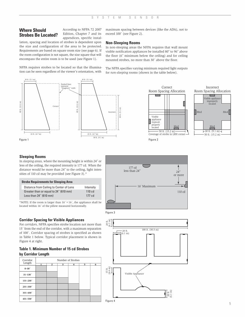
According to NFPA 72 2007 Edition, Chapter 7 and its appendices, specific instal-
lation, spacing and location of strobes is dependent upon the size and configuration of the area to be protected. Requirements are based on square room size (see page 6). If the room configuration is not square, the size square that will encompass the entire room is to be used (see Figure 1).
NFPA requires strobes to be located so that the illumina-tion can be seen regardless of the viewer’s orientation, with
S Y S T E M S E N S O R
5
Where Should Strobes Be Located?
maximum spacing between devices (like the ADA), not to exceed 100´ (see Figure 2).
Non-Sleeping RoomsIn non-sleeping areas the NFPA requires that wall mount visible notification appliances be installed 80˝ to 96˝ above the floor (6˝ minimum below the ceiling) and for ceiling mounted strobes, no more than 30´ above the floor.
The NFPA specifies varying minimum required light outputs for non-sleeping rooms (shown in the table below).
Visibleappliance(typical)properlylocated 30cd
50 ft. (15.2 m)Coverage of strobe in LRH corner
CorrectRoom Spacing Allocation
30cd
30cd 30cd
50 ft. (15.2 m)
IncorrectRoom Spacing Allocation
30 ft. (9.1 m)
Visible applianceimproperly
located
Strobe Requirements for Sleeping Area
Distance from Ceiling to Center of Lens Intensity Greater than or equal to 24˝ (610 mm) 110 cd Less than 24˝ (610 mm) 177 cd
*NOTE: If the room is larger than 16´×16´, the appliance shall be located within 16´ of the pillow measured horizontally.
16′ Maximum
110 cd
177 cdless than 24″ 24″
or more
Table 1. Minimum Number of 15 cd Strobesby Corridor Length
10 ft. (3.1 m)
Correct
22 ft. (6.7 m)
40 f
t. (
12.2
m)
Dashed linesrepresent“imaginary” walls
10 ft. (3.1 m)
Incorrect
22 ft. (6.7 m)
30 ft. (9.1 m)
40 f
t. (
12.2
m)
30 f
t. (
9.1
m)
Sleeping RoomsIn sleeping areas, where the mounting height is within 24˝ or less of the ceiling, the required intensity is 177 cd. When the distance would be more than 24˝ to the ceiling, light inten-sities of 110 cd may be provided (see Figure 3).*
Corridor Spacing for Visible AppliancesFor corridors, NFPA specifies strobe location not more than 15´ from the end of the corridor, with a maximum separation of 100´. Corridor spacing of strobes is specified as shown in Table 1 below. Typical corridor placement is shown in Figure 4 at right.
20 ft.(6.1 m)
Visible Appliance
20 f
t.(6
.1 m
)
20 f
t.(6
.1 m
)
15 f
t.(4
.6 m
)
100 ft. (30.5 m)
Figure 1 Figure 2
Figure 3
Figure 4
A U D I B L E / V I S I B L E A P P L I A N C E R E F E R E N C E G U I D E
6
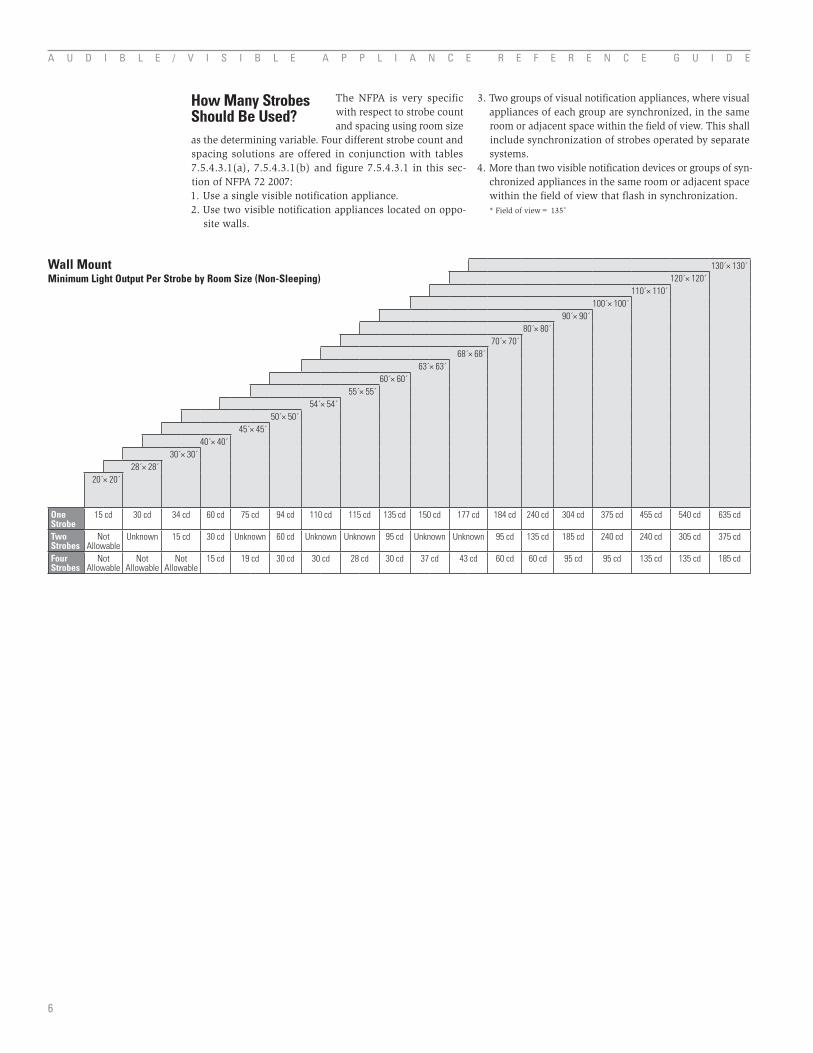
The NFPA is very specific with respect to strobe count and spacing using room size
as the determining variable. Four different strobe count and spacing solutions are offered in conjunction with tables 7.5.4.3.1(a), 7.5.4.3.1(b) and figure 7.5.4.3.1 in this sec-tion of NFPA 72 2007:1. Use a single visible notification appliance. 2. Use two visible notification appliances located on oppo-
site walls.
3. Two groups of visual notification appliances, where visual appliances of each group are synchronized, in the same room or adjacent space within the field of view. This shall include synchronization of strobes operated by separate systems.
4. More than two visible notification devices or groups of syn-chronized appliances in the same room or adjacent space within the field of view that flash in synchronization.
* Field of view= 135˚
How Many StrobesShould Be Used?
Wall MountMinimum Light Output Per Strobe by Room Size (Non-Sleeping)
130´× 130´120´× 120´
110´× 110´100´× 100´
90´× 90´80´× 80´
70´× 70´68´× 68´
63´× 63´60´× 60´
55´× 55´54´× 54´
50´× 50´45´× 45´
40´× 40´30´× 30´
28´× 28´20´× 20´
One Strobe
15 cd 30 cd 34 cd 60 cd 75 cd 94 cd 110 cd 115 cd 135 cd 150 cd 177 cd 184 cd 240 cd 304 cd 375 cd 455 cd 540 cd 635 cd
Two Strobes
NotAllowable
Unknown 15 cd 30 cd Unknown 60 cd Unknown Unknown 95 cd Unknown Unknown 95 cd 135 cd 185 cd 240 cd 240 cd 305 cd 375 cd
Four Strobes
Not Allowable
NotAllowable
Not Allowable
15 cd 19 cd 30 cd 30 cd 28 cd 30 cd 37 cd 43 cd 60 cd 60 cd 95 cd 95 cd 135 cd 135 cd 185 cd
The installation and per-formance requirements for audible/visible appliances in general are addressed in three documents: 1. ADA, a civil rights law prohibiting discrimination on the basis of disability; 2. IFC 2006
Edition/ANSI 117.1–2003 ‘Accessible and Usable Buildings and Facilities’, a standard on accessibility designed to be adopted as part of a building code; and, 3. NFPA 72, the National Fire Alarm Code, 2007 edition, an installation stan-dard for fire alarm systems normally not adopted directly into law, but referenced in a building code as the standard to be followed.
From a building design and construction standpoint, IFC 2006 Edition/ANSI A117.1–2003 and NFPA 72, 2007 edi-tion, both recognize ceiling-mount visual alarm appliances and describe the requirements for intensity, mounting, and placement for such appliances. The current version of the ADAAG (1991) does not. While compliance with all three is generally required, the only method to satisfy the require-ments of ANSI A117.1/NFPA 72 and the ADAAG, and thus to be able to install ceiling-mounted appliances, is to claim equivalent facilitation, which is not currently allowed by ADA (though it may soon be allowed). Or, ask for a vari-ance from the Authority Having Jurisdiction.
The definition of equivalent facilitation is provided within Chapter 1, Section 103 of the ADAAG, which states the following:“Alternatives to specific requirements that provide equal or greater access are permitted. This provides flexibility for new technologies and innovative design solutions that may not have been taken into account when the ADAAG was developed.”
ADAAG and Ceiling-Mount Visual Alarm AppliancesThe ADAAG has great importance to members of the fire alarm industry because it is used as a reference to define the provisions for accessibility within the design and con-struction of accessible buildings. However, the ADAAG has not been updated since 1991 and does not reflect recent technological advances within the industry. These advances improved the ability of fire alarm devices, in general, and audible/visible devices, in particular, to provide notification of a fire condition and the need to evacuate an area. Since the introduction of the ADAAG, the industry has made sig-nificant advances in the design of audible/visible appliances, specifically in the area of ceiling-mounted devices, which are not addressed by the current ADAAG.
On November 16, 1999, a proposed update of the ADAAG was published in the Federal Register for public comment. The intent is to harmonize the ADAAG with the model codes and the national standard, as well as to reflect technological developments, such as ceiling-mounted devices, that have occurred since the current 1991 version, while continuing to meet the needs of people with disabilities. The proposed version of the ADAAG addresses ceiling-mounted audible/visible devices, in terms of installation and performance,
S Y S T E M S E N S O R
7
Usage of Ceiling-Mounted Visual Alarm Appliances as Prescribed by Key Standards, Laws, and Codes
in a manner that is generally consistent with the current versions of NFPA72 and ICC/ANSI A117.1. However, the proposed update has not been adopted into law, and until such time the current ADAAG (1991) remains in effect, and equivalent facilitation must be demonstrated in order to use ceiling-mounted devices in those installations requir-ing compliance with the ADAAG.
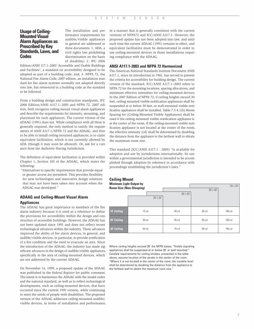
ANSI A117.1-2003 and NFPA 72 HarmonizedThe American National Standards Institute Document ANSI A117.1, since its introduction in 1961, has served to present the criteria for accessibility for building design. The current version of the standard, ICC/ANSI A117.1–2003 refers to NFPA 72 for the mounting locations, spacing allocations, and minimum effective intensities for ceiling-mounted devices. In the 2007 Edition of NFPA 72, if ceiling heights exceed 30 feet, ceiling mounted visible notification appliances shall be suspended at or below 30 feet, or wall-mounted visible noti-fication appliances shall be installed. Table 7.5.4.1(b) Room Spacing for (Ceiling-Mounted Visible Appliances) shall be used if the ceiling mounted visible notification appliance is at the center of the room. If the ceiling-mounted visible noti-fication appliance is not located at the center of the room, the effective intensity (cd) shall be determined by doubling the distance from the appliance to the farthest wall to obtain the maximum room size.
This standard (ICC/ANSI A117.1 - 2003) “is available for adoption and use by jurisdictions internationally. Its use within a governmental jurisdiction is intended to be accom-plished through adoption by reference in accordance with proceedings establishing the jurisdiction’s laws.”
Ceiling MountMinimum Light Output byRoom Size (Non-Sleeping)
Where ceiling heights exceed 30´ the NFPA states, “Visible signaling appliances shall be suspended at or below 30´ or wall mounted.” Candela requirements for ceiling strobes, presented in the table above, assume location of the strobe in the center of the room. “Where it is not located in the center of the room, the candela level shall be determined by doubling the distance from the appliance to the farthest wall to obtain the maximum room size.”
70´× 70´50´× 50´
30´× 30´20´× 20´
10´ Ceiling 15 cd 30 cd 95 cd 185 cd
20´ Ceiling 30 cd 45 cd 95 cd 185 cd
30´ Ceiling 55 cd 75 cd 95 cd 185 cd

People who are vulnerable to photosensitive epilepsy have voiced concern over the cumu-lative effect of seeing multiple flashing strobes in the field of view.
An example of this would be an individual standing at the cross-point of an “L” shaped corridor that contains multiple strobes. During an alarm or test of a system, the person could be exposed to a cumulative flash rate that might increase the probability of seizure and photosensitive response.
Although aggregate strobe flash rates in a fire alarm system and their relationship to those persons with photosensi-tive epilepsy are not directly referenced in any current law or standard, it is an issue that should be addressed with
diligence when installing and/or upgrading fire alarm systems.
Although one solution involves synchronized (simultane-ous flashing) strobes, other options have been outlined by NFPA and the proposed ADAAG. The NFPA makes it clear in Chapter 7, Section 7.5.4.3 that synchronization is only one of several installation configurations that the systems designer can use to minimize multiple strobes flashing in an individual’s field of view. These four options are outlined on page 6. The 2007 edition of NFPA added that the strobe syn-chronization requirements of Chapter 7 do not apply where visible notification appliances located inside the building are viewed from outside of the building. In 1996 the NFPA changed its maximum acceptable strobe flash rate from 3 Hz to 2 Hz in an effort to reduce strobe flash rates in an individual’s field of view.
A U D I B L E / V I S I B L E A P P L I A N C E R E F E R E N C E G U I D E
8
ConclusionFrom a building design and construction standpoint, ANSI A117.1, the building standard for accessibility and NFPA 72, the National Fire Alarm Code, both recognize ceiling-mount visual alarm appliances and describe the requirements for intensity, mounting, and placement for such appliances. As noted, the current version of the ADAAG (1991) does not. While compliance with all three is generally required, the only method to satisfy the requirements of ANSI A117.1/NFPA 72 and the ADAAG, and thus to be able to install ceil-ing-mounted appliances, is to claim equivalent facilitation.
Equivalent facilitation, as defined in the current ADAAG Chapter 1, Section 103, states “alternatives to specific require-
ments that provide equal or greater access are permitted”. The ADAAG further states that equivalent facilitation “pro-vides flexibility for new technologies and innovative design solutions that may not have been taken into account when ADAAG was developed”.
Equivalent facilitation, in the instance of visual alarm appliances, may be used to demonstrate that any proposed substitute will deliver the minimum illumination (or light intensity) requirements. The use of ceiling-mounted visual alarm appliances in lieu of wall-mounted appliances, as sup-ported by a demonstration of equivalent facilitation, requires the approval of the appropriate authority having jurisdic-tion (AHJ).
What About Photosensitive Epilepsy and Strobe Flash Rates?

The focus of notification appli-ance code development over the last several years centered around the visible portion of
the devices to aid hearing impaired individuals during a fire emergency. Even with this focus it is important to remember that there are code requirements for the audible portion of the device as well. Although the ADA has audibil-ity requirements, NFPA 72 Chapter 7 has the more stringent set; therefore, the highlights of NFPA’s notification appliance audibility requirements are outlined below.
As defined by the NFPA, the location of an audible appli-ance shall be not less than 90″ above the floor and not less than 6″ below the ceiling. This requirement is superseded by strobe location requirements when an audible appliance is installed in combination with a strobe.
Temporal Evacuation SignalThe most recent audibility requirement to be adopted by the NFPA is the Temporal Code. This code was developed to establish a universal evacuation signal to lessen confusion as to whether an alarm represents an emergency requirnig complete evacuation of the building.
S Y S T E M S E N S O R
9
Audibility Requirements
Key:Phase (a) signal is “on” for 0.5 sec ± 10%Phase (b) signal is “off” for 0.5 sec ± 10%Phase (c) signal is “off” for 1.5 sec ± 10% [(c) = (a) + 2(b)]Total cycle lasts for 4 sec ± 10%
Time (sec)
ON0.5 Sec.
OFF0.5 Sec.
OFF0.5 Sec.
OFF1.5 Sec.
ON0.5 Sec.
CYCLE4 Sec.
ON0.5 Sec.
ON0.5 Sec.
(a) (a) (a)
(c)
(a)
(b) (b)
*Note: The temporal evacuation signal is a system requirement and is addressed in NFPA 72, Chapter 7.
This tone pattern is a 0.5 second on phase, followed by a 0.5 off phase for three successive on phases, followed by an off phase of 1.5 seconds. The pattern is then repeated for a minimum of 180 seconds.
Public Mode Sound LevelNFPA’s minimum public mode dBA output is the highest of two possible scenarios measured 5′ above the floor.
• 15dBAaboveaverageambientsound• 5dBAabovethemaximumsoundlevelwithadura-
tion of at least 60 seconds.NFPA’s maximum public mode dBA output is 110 dBA anywhere.
The ADA’s public mode audibility requirements are the same as NFPA’s except NFPA requires a minimum of 75 dBA pres-ent at the pillow in sleeping areas.
Private Mode Sound LevelNFPA’s minimum private mode dBA output is the highest of three possible scenarios measured 5′ above the floor.
• 10dBAaboveaverageambientsound• 5dBAabovethemaximumsoundlevelwithadura-
tion of at least 60 secondsNFPA’s maximum private mode dBA output is 110 dBA any-where, whereas ADA allows 120 dBA maximum.
Sleeping Area Sound LevelNFPA’s minimum sleeping area dBA output is the highest of three possible scenarios measured 5′ above the floor.
• Soundlevelofatleast75dBA• 15dBAaboveaverageambientsound• 5dBAabovethemaximumsoundlevelwithadura-
tion of at least 60 secondsNFPA’s maximum sleeping area dBA output is 120 dBA anywhere.
Voltage drops occur in the wir-ing, causing the voltage at the end of the loop to be lower than the supply voltage. In laying
out a circuit, it is important to prove that the voltage supplied to the last device on the loop is greater than its minimum operating voltage designated by UL testing.
A quick, worst case estimate of voltage drop in the wir-ing can be obtained by assuming that all of the appliances on the loop are lumped at the end furthest from the power supply. To do this estimate, you must know the following about the circuit:
• Theminimumpossiblevoltageatwhichtheparticular power supply will operate as defined by UL testing. This is typically 15% below the nominal output of the power supply.
• Theminimumvoltagesuppliedtothecircuit.• Thetotalcurrentdrawnbytheappliancesonthe
circuit.• Thelengthofthecircuit,fromthepowersupplyto
the last device.• Thewiresize.• Thetotalwiringresistance(determinedfromthe
length of the circuit and the wire size).
When calculating the voltage available to the last device, it is necessary to consider the voltage drop due to the resis-tance of the wire. The thicker the wire, the smaller the voltage drop. Generally, for purposes of determining the wire size necessary for the system, it is best to consider all of the devices as “lumped” on the end of the supply circuit to simulate worst case. For the most accurate voltage drop calculations use the System Sensor voltage drop calculator available on the web or CD-ROM.
Approximate wire resistance:18 AWG solid: 8 ohms/1000 ft.16 AWG solid: 5 ohms/1000 ft.14 AWG solid: 3 ohms/1000 ft.12 AWG solid: 2 ohms/1000 ft.NOTE: If Class A wiring is installed, the wire length may be up to twice as long as on non-fault tolerant circuits.
The total wiring resistance is determined by multiplying the ohms/foot of the wire being used by the total length of the wiring. The length of the circuit must be multiplied by two to get the total length of the wiring (to account for two conductors in the wire).
With this information the voltage drop in the wiring can be determined using the formula:
VDROP = (Total Current Draw) × (Total Wiring Resistance)
The voltage at the end of the circuit is then determined by the formula
VEOL= VSUPPLY – VDROP
The above calculations should be made using the mini-mum supply voltage specified by the manufacturer of the supply. This value is typically 15% below the nominal volt-age, so calculations for 24-volt supplies are made using 20.4 volts, and calculations for 12-volt supplies are made using 10.2 volts.
A U D I B L E / V I S I B L E A P P L I A N C E R E F E R E N C E G U I D E
10
Voltage Drop Calculations
If the calculated result for VEOL is less than the minimum rated voltage of the appliances being used, then changes need to be made in the design of the circuit. Somewhat more favorable results may also be attained by analyzing the circuit in more detail, where the exact location of each appliance in the circuit is taken into account. This approach is most easily accomplished by using a computerized pro-gram, like the one on the System Sensor website.
ExampleA 24-volt notification circuit needs to drive 12 appliances. Each appliance has a rated operating voltage range of 16 – 33 volts and draws 125 mA. The length of the circuit is 250 feet from the power supply to the last device. The proposed wire is 18 AWG solid copper. Will this system provide ade-quate voltage to the last device on the circuit?
From the wiring tables, the resistance of the wire is 8.08 ohms/1000 feet. The total length of the wire is 500 feet (250 feet of two wire cable). Therefore, the total resistance of the wire is
RWIRING = 8.08 × 500/1000 = 4.04 ohms
The total current in the circuit isITOTAL = 12 appliances × 125 mA/appliance x .001 amp/mA = 1.5 amps
Voltage dropped (or lost) in the wiring thus becomesVDROP = ITOTAL × RWIRING = 1.5 × 4.04 = 6.06 volts
Voltage available at the end of the circuit is calculated by sub-tracting VDROP from the supply voltage. Assuming a worst case supply voltage 15% below nominal, the result is
VEOL = 20.4 – 6.06 = 13.8 volts
Since this voltage is less than the operating voltage of the appliances (16 volts), the circuit design is not acceptable. If we switch from 18 AWG wire to 16 AWG and repeat the calculations
RWIRING = 5.08 × 500/1000 = 2.54 ohmsITOTAL = 12 appliances × 125 mA/appliance × .001 amp/mA = 1.5 amps
VDROP = ITOTAL × RWIRING = 1.5 × 2.54 = 3.8 voltsVEOL = 20.4 – 3.8 = 16.6 volts
Since the worst case voltage at the end of the circuit is now greater than the minimum voltage required for the appli-ances, this design would be acceptable.
Voltage drop calculations should be done during the plan-ning stages of an installation, prior to installing any wiring or devices. There is no simple fix if it turns out that a fully installed system cannot meet the requirements of the appli-ances connected to it.
In designing the notification circuit, it is also important to make sure that the power supply is capable of supplying the appropriate voltage and current levels required by the appliances.
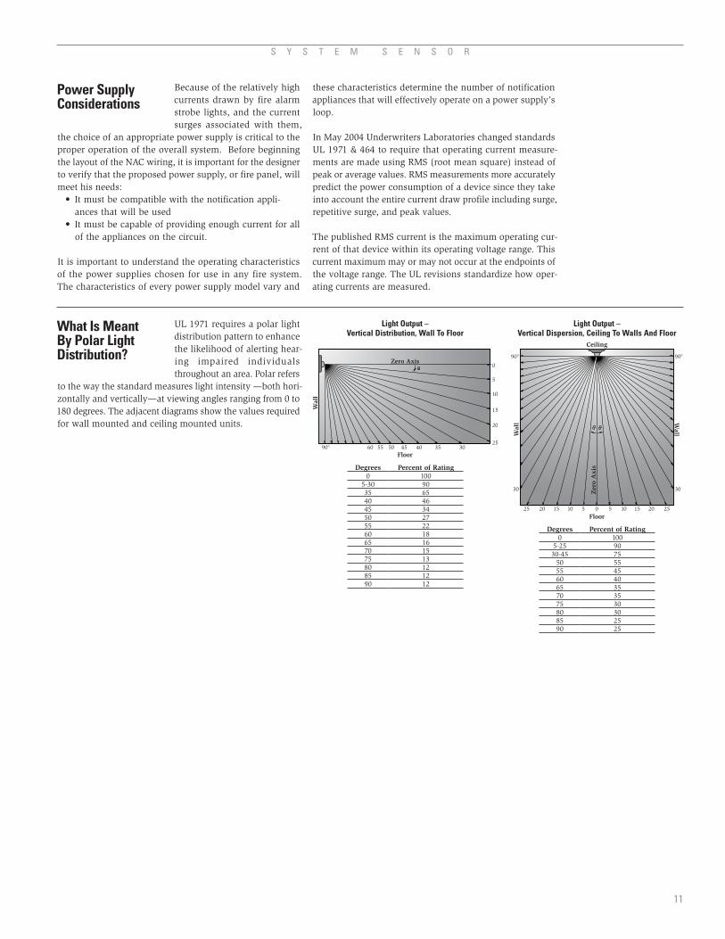
UL 1971 requires a polar light distribution pattern to enhance the likelihood of alerting hear-ing impaired individuals throughout an area. Polar refers
to the way the standard measures light intensity —both hori-zontally and vertically—at viewing angles ranging from 0 to 180 degrees. The adjacent diagrams show the values required for wall mounted and ceiling mounted units.
Because of the relatively high currents drawn by fire alarm strobe lights, and the current surges associated with them,
the choice of an appropriate power supply is critical to the proper operation of the overall system. Before beginning the layout of the NAC wiring, it is important for the designer to verify that the proposed power supply, or fire panel, will meet his needs:
• Itmustbecompatiblewiththenotificationappli-ances that will be used
• Itmustbecapableofprovidingenoughcurrentforallof the appliances on the circuit.
It is important to understand the operating characteristics of the power supplies chosen for use in any fire system. The characteristics of every power supply model vary and
S Y S T E M S E N S O R
11
What Is Meant By Polar Light Distribution?
Light Output –Vertical Distribution, Wall To Floor
Light Output –Vertical Dispersion, Ceiling To Walls And Floor
Degrees Percent of Rating0 100
5-30 9035 6540 4645 3450 2755 2260 1865 1670 1575 1380 1285 1290 12
Degrees Percent of Rating0 100
5-25 9030-45 75
50 5555 4560 4065 3570 3575 3080 3085 2590 25
Power Supply Considerations
these characteristics determine the number of notification appliances that will effectively operate on a power supply’s loop.
In May 2004 Underwriters Laboratories changed standards UL 1971 & 464 to require that operating current measure-ments are made using RMS (root mean square) instead of peak or average values. RMS measurements more accurately predict the power consumption of a device since they take into account the entire current draw profile including surge, repetitive surge, and peak values.
The published RMS current is the maximum operating cur-rent of that device within its operating voltage range. This current maximum may or may not occur at the endpoints of the voltage range. The UL revisions standardize how oper-ating currents are measured.
Ceiling
Floor
90°
30
25 2520 2015 1510 105 50
30
90°
Zer
o A
xis
WallW
all
Floor
Wal
l
Zero Axis
25
20
15
10
5
0
90° 60 55 50 45 40 35 30
A U D I B L E / V I S I B L E A P P L I A N C E R E F E R E N C E G U I D E
12
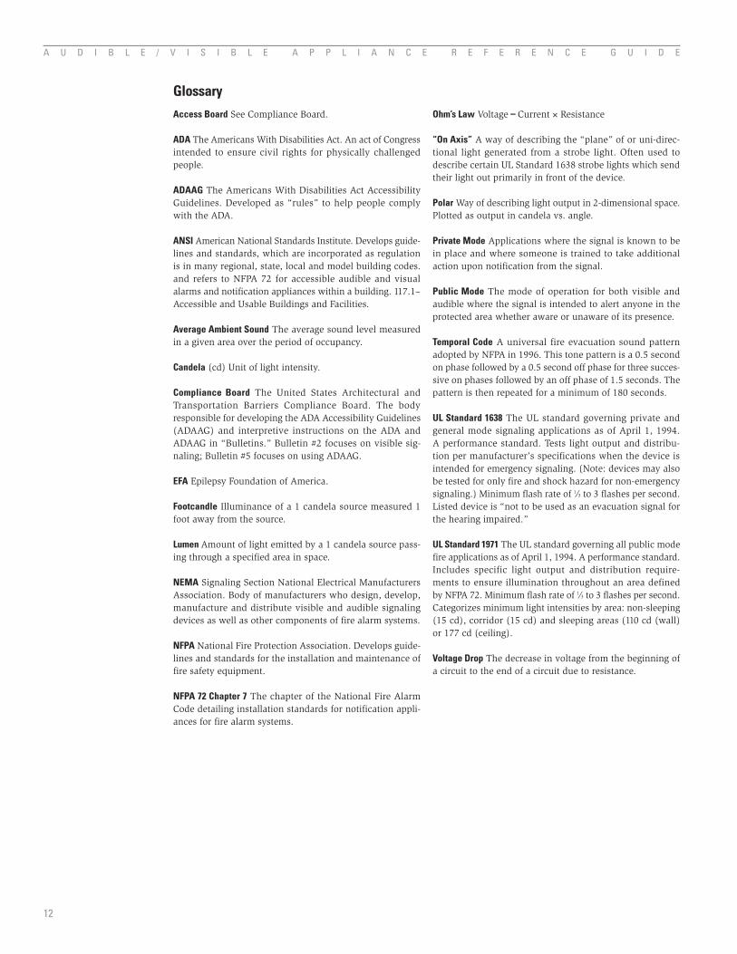
Access Board See Compliance Board.
ADA The Americans With Disabilities Act. An act of Congress intended to ensure civil rights for physically challenged people.
ADAAG The Americans With Disabilities Act Accessibility Guidelines. Developed as “rules” to help people comply with the ADA.
ANSI American National Standards Institute. Develops guide-lines and standards, which are incorporated as regulation is in many regional, state, local and model building codes. and refers to NFPA 72 for accessible audible and visual alarms and notification appliances within a building. 117.1–Accessible and Usable Buildings and Facilities.
Average Ambient Sound The average sound level measured in a given area over the period of occupancy.
Candela (cd) Unit of light intensity.
Compliance Board The United States Architectural and Transportation Barriers Compliance Board. The body responsible for developing the ADA Accessibility Guidelines (ADAAG) and interpretive instructions on the ADA and ADAAG in “Bulletins.” Bulletin #2 focuses on visible sig-naling; Bulletin #5 focuses on using ADAAG.
EFA Epilepsy Foundation of America.
Footcandle Illuminance of a 1 candela source measured 1 foot away from the source.
Lumen Amount of light emitted by a 1 candela source pass-ing through a specified area in space.
NEMA Signaling Section National Electrical Manufacturers Association. Body of manufacturers who design, develop, manufacture and distribute visible and audible signaling devices as well as other components of fire alarm systems.
NFPA National Fire Protection Association. Develops guide-lines and standards for the installation and maintenance of fire safety equipment.
NFPA 72 Chapter 7 The chapter of the National Fire Alarm Code detailing installation standards for notification appli-ances for fire alarm systems.
GlossaryOhm’s Law Voltage=Current × Resistance
“On Axis” A way of describing the “plane” of or uni-direc-tional light generated from a strobe light. Often used to describe certain UL Standard 1638 strobe lights which send their light out primarily in front of the device.
Polar Way of describing light output in 2-dimensional space. Plotted as output in candela vs. angle.
Private Mode Applications where the signal is known to be in place and where someone is trained to take additional action upon notification from the signal.
Public Mode The mode of operation for both visible and audible where the signal is intended to alert anyone in the protected area whether aware or unaware of its presence.
Temporal Code A universal fire evacuation sound pattern adopted by NFPA in 1996. This tone pattern is a 0.5 second on phase followed by a 0.5 second off phase for three succes-sive on phases followed by an off phase of 1.5 seconds. The pattern is then repeated for a minimum of 180 seconds.
UL Standard 1638 The UL standard governing private and general mode signaling applications as of April 1, 1994. A performance standard. Tests light output and distribu-tion per manufacturer’s specifications when the device is intended for emergency signaling. (Note: devices may also be tested for only fire and shock hazard for non-emergency signaling.) Minimum flash rate of 1⁄3 to 3 flashes per second. Listed device is “not to be used as an evacuation signal for the hearing impaired.”
UL Standard 1971 The UL standard governing all public mode fire applications as of April 1, 1994. A performance standard. Includes specific light output and distribution require-ments to ensure illumination throughout an area defined by NFPA 72. Minimum flash rate of 1⁄3 to 3 flashes per second. Categorizes minimum light intensities by area: non-sleeping (15 cd), corridor (15 cd) and sleeping areas (110 cd (wall) or 177 cd (ceiling).
Voltage Drop The decrease in voltage from the beginning of a circuit to the end of a circuit due to resistance.
©2007 System Sensor. The company reserves the right to change specifications at any time. A05-0218-005 • 5/07 • #1748
NOTE: System Sensor does not approve, inspect, or certify any installations, procedures, equipment, or materials. In determining the acceptability of installations or procedures, equipment, or materials, the authority having jurisdiction may base acceptance on compliance with NFPA or other appropri-ate standards. The authority having jurisdiction may also refer to the listings or labeling practices of an organization concerned with product evaluations which is in a position to determine compliance with appropriate standards for the current production of listed items. The information in this guide has been provided in an attempt to assist in making this decision and should in no way be construed as a formal approval or certification.
Related Documents