Attitude Determination and Control of Satellites

Attitude Dynamics and Control
Dec 07, 2015
Attitude dynamics and control
Welcome message from author
This document is posted to help you gain knowledge. Please leave a comment to let me know what you think about it! Share it to your friends and learn new things together.
Transcript

Attitude Determination and Control of Satellites

Introduction
• Attitude Determination and Control Subsystem(ADCS)
- Senses the orientation of spacecraft relative to reference plane usually inertial
- Stabillizes the spacecraft
- Orients the spacecraft in desired direction

Attitude control
Needed because
• Payload requirements
Eg. Focusing the satellite camera to a particular direction
• Communication requirements
Pointing the antenna towards ground
• Power system requirements
Tracking the sun to achieve maximum power generation

Components of ADCS
• Sensors- To determine the orientation of the satellite
• Algorithms-To calculate the deviation from the desired orientation and to generate actuation command to counter the deviation
• Actuators-To act upon the signals given by the control algorithms and to produce the necessary torques
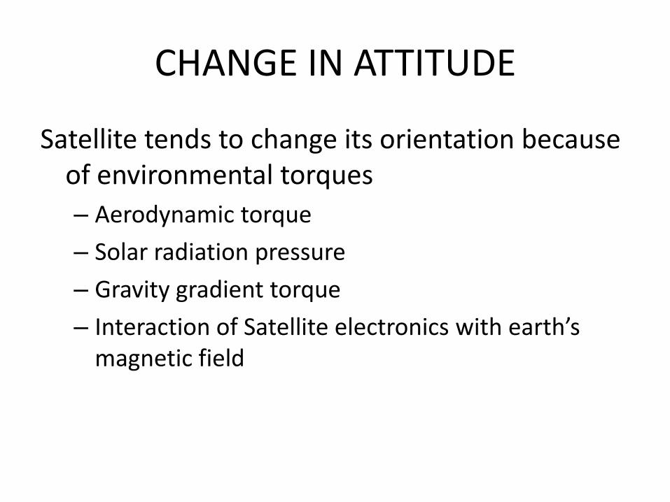
CHANGE IN ATTITUDE
Satellite tends to change its orientation because of environmental torques
– Aerodynamic torque
– Solar radiation pressure
– Gravity gradient torque
– Interaction of Satellite electronics with earth’s magnetic field
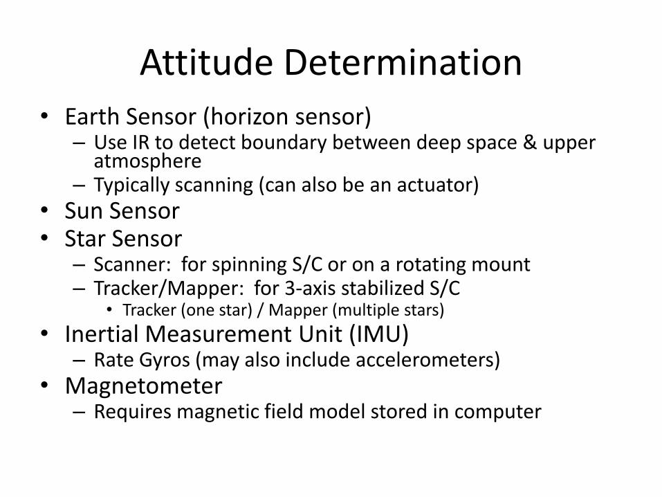
Attitude Determination • Earth Sensor (horizon sensor)
– Use IR to detect boundary between deep space & upper atmosphere
– Typically scanning (can also be an actuator) • Sun Sensor • Star Sensor
– Scanner: for spinning S/C or on a rotating mount – Tracker/Mapper: for 3-axis stabilized S/C
• Tracker (one star) / Mapper (multiple stars)
• Inertial Measurement Unit (IMU) – Rate Gyros (may also include accelerometers)
• Magnetometer – Requires magnetic field model stored in computer

Attitude Control
• Actuators come in two types
– Passive
• Gravity Gradient Boom
• Spinning
– Active
• Thrusters
• Wheels
• Gyros
• Torque Rods

Reference frames
• Earth Centered Inertial Frame: Non rotating reference frame denoted by .
Origin : Center of Earth
x –axis : Points towards vernal equinox
y – axis: 90⁰ east in the equatorial plane
z - axis: Extends through North pole


• Earth-Centered Earth Fixed (ECEF) Frame:
x and y axes rotate with the hemisphere relative to ECI frame
origin: center of earth
x-axis: Points toward the intersection of Greenwich meridian and equator
z-axis: Extends through the North pole and rotation is about z axis
y-axis: Completes right handed system.


• Orbit Frame:
Origin: Center of mass of the satellite
x-axis: Points in the direction of motion tangentially to the orbit
z-axis: Points Nadhir (center of Earth)
y-axis: Completes right handed system
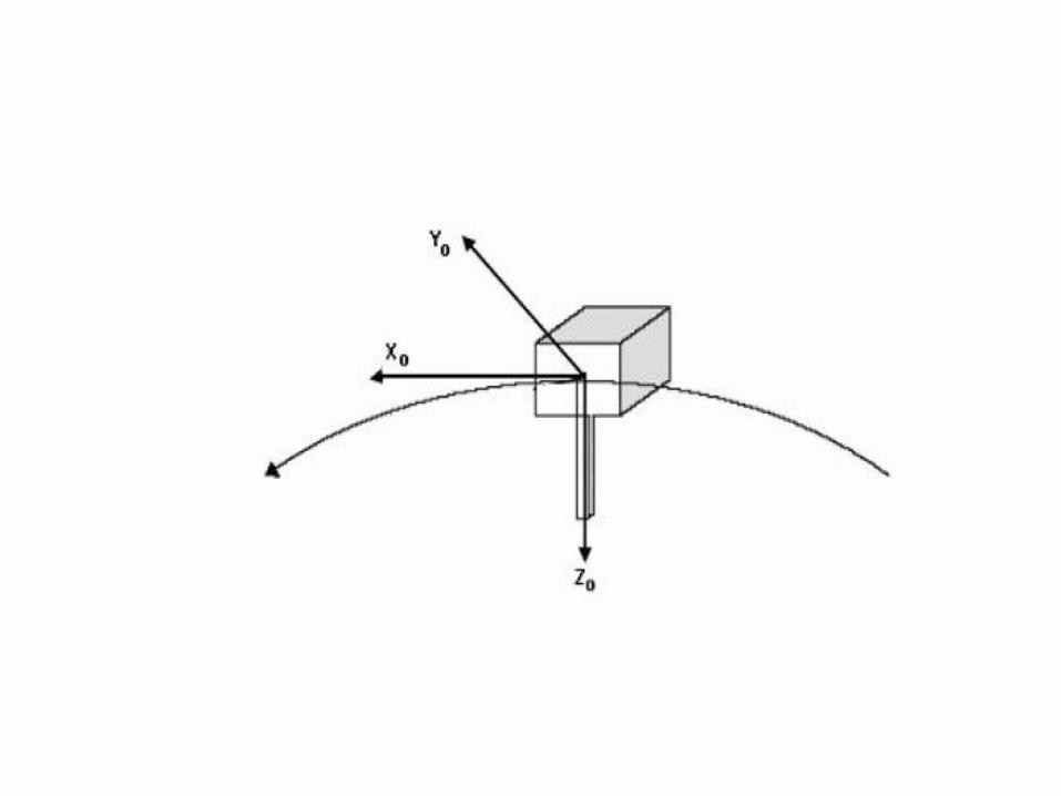

• Body frame:
Origin: Coincides with the center of mass of the satellite.
x and y axes: Coincides with the orbit frame axes when the satellite has an attitude of 0⁰ in roll, pitch and yaw.
z-axis: Nadhir side of satellite


Rotation Matrix
Rotation matrix is a description of the rotational relationship between two reference frame.
The rotation matrix R from frame a to b is denoted as Rᵇₐ.
Rotation of a vector from one frame to another frame be given using Rᵇₐ as
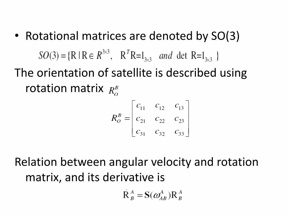
• Rotational matrices are denoted by SO(3)
The orientation of satellite is described using rotation matrix
Relation between angular velocity and rotation matrix, and its derivative is

• Attitude Representation:
Most widely used methods:
-Euler angles
-Unit Quaternions
Euler Angles:
-Uses roll (ф), pitch (ϴ), yaw (ψ)


• Transforming the body from the inertial axes to rotated body fixed axes using a rotation matrix:
Where I, j, k are chosen rotation axes and
are transposes of the elementary rotation matrices about their respective axes.
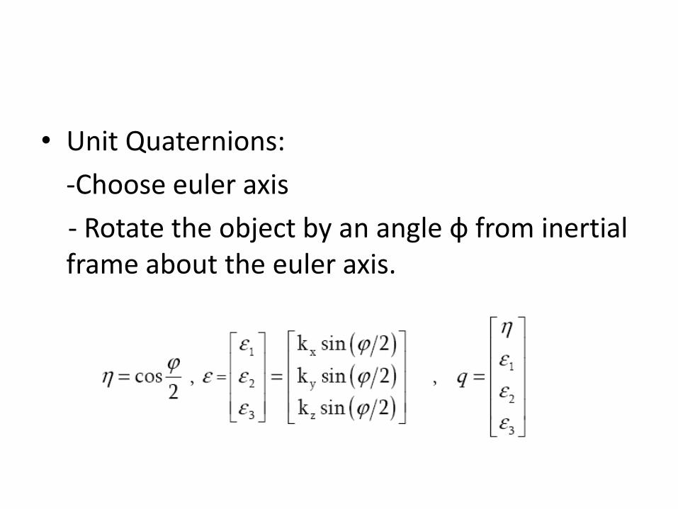
• Unit Quaternions:
-Choose euler axis
- Rotate the object by an angle ф from inertial frame about the euler axis.

Inertia Matrix
Inertia matix Iₒ about origin is defined as

Dynamics of Satellite
Consider satellite as rigid body h = r x p h= IѠ Where h – angular momentum r – position vector p – linear momentum I – moment of inertia Ѡ – angular velocity
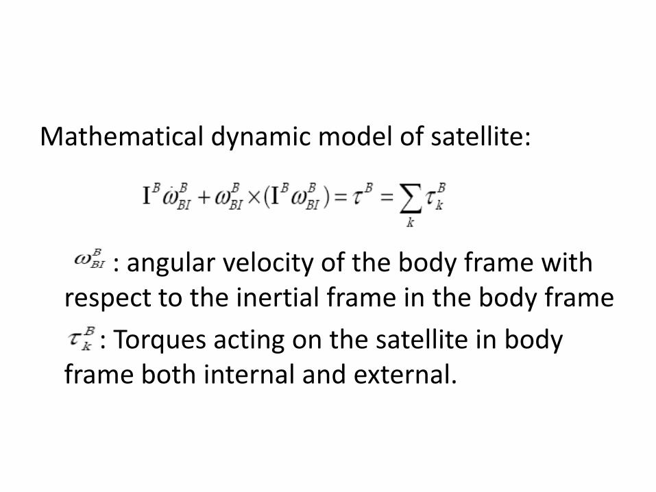
Mathematical dynamic model of satellite:
: angular velocity of the body frame with respect to the inertial frame in the body frame
: Torques acting on the satellite in body frame both internal and external.

Modeling of Reaction wheel
• Torque produced by reaction wheel:
: Torque produced by reaction wheel in body frame
is angular momentum of reaction wheels
is friction of reaction wheel
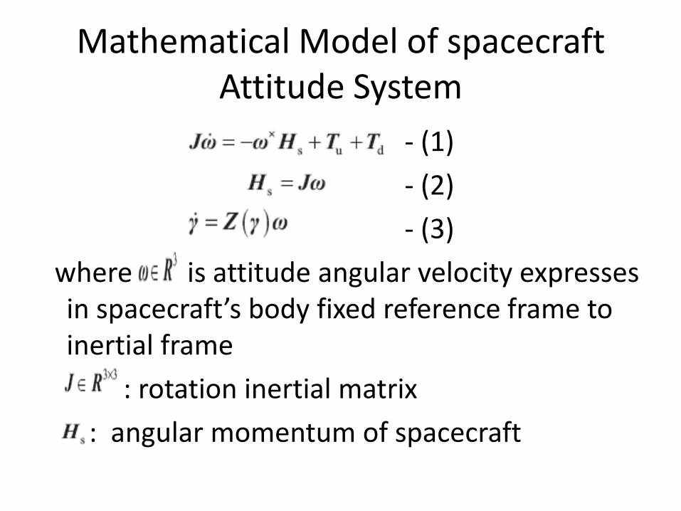
Mathematical Model of spacecraft Attitude System
- (1)
- (2)
- (3)
where is attitude angular velocity expresses in spacecraft’s body fixed reference frame to inertial frame
: rotation inertial matrix
: angular momentum of spacecraft
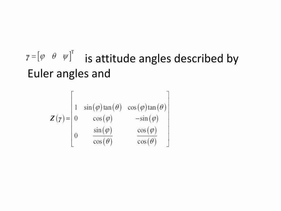
is attitude angles described by Euler angles and

References
• LI Long, Hou Jianwen. Adaptive Sliding Mode Based Controller Design for Spacecraft Attitude Stabilization, IEEE transactions, 2015
• Attitude determination and control by James R Wertz
• Spacecraft Dynamics and Control by Marcel J. SIDI,1997
Related Documents