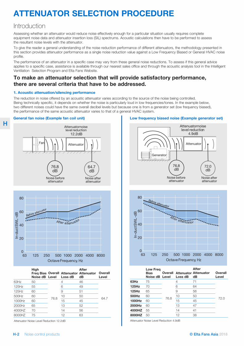
Noise control products H-2 © Elta Fans Asia 2018 H ATTENUATOR SELECTION PROCEDURE Low Freq Bias Noise dB Overall Level Attenuator Loss dB After Attenuator dB Overall Level 63Hz 75 76.8 4 71 72.0 125Hz 70 6 64 125Hz 65 9 56 500Hz 60 10 50 1000Hz 60 15 45 2000Hz 60 13 47 4000HZ 55 14 41 8000HZ 50 12 38 Attenuator Noise Level Reduction 4.9dB High Freq Bias Noise dB Overall Level Attenuator Loss dB After Attenuator dB Overall Level 63Hz 50 76.8 4 46 64.7 125Hz 55 6 49 125Hz 60 9 51 500Hz 60 10 50 1000Hz 60 15 45 2000Hz 65 13 52 4000HZ 70 14 56 8000HZ 75 12 63 Attenuator Noise Level Reduction 12.2dB In-duct SWL -dB 125 63 250 500 1000 2000 4000 8000 0 20 40 60 80 OctaveFrequency, Hz B e fore atte nuator A f te at r te n u a t or Generator Attenuator Noise before attenuator Noise after attenuator 76.8 dB 72.0 dB Attenuatornoise level reduction 4.9dB 0 20 40 60 80 125 63 250 500 1000 2000 4000 8000 OctaveFrequency, Hz In-duct SWL -dB B e fore atte nuator A f te at r t e n u a t or Attenuator Noise after attenuator Fan 76.8 dB 12.2dB Attenuatornoise level reduction 64.7 dB Noise before attenuator General fan noise (Example fan coil unit) Low frequency biased noise (Example generator set) Introduction Assessing whether an attenuator would reduce noise effectively enough for a particular situation usually requires complete equipment noise data and attenuator insertion loss (SIL) spectrums. Acoustic calculations then have to be performed to assess the resultant noise levels with the attenuator. To give the reader a general understanding of the noise reduction performance of different attenuators, the methodology presented in this section provides attenuator performance as a single noise reduction value against a Low Frequency Biased or General HVAC noise profile. The performance of an attenuator in a specific case may vary from these general noise reductions. To assess if this general advice applies to a specific case, assistance is available through our nearest sales office and through the acoustic analysis tool in the Intelligent Ventilation Selection Program and Elta Fans Website. To make an attenuator selection that will provide satisfactory performance, there are several criteria that have to be addressed. 1. Acoustic attenuation/silencing performance The reduction in noise offered by an acoustic attenuator varies according to the source of the noise being controlled. Being technically specific, it depends on whether the noise is particularly loud in low frequencies/tones. In the example below, two different noises could have the same overall decibel levels but because one is from a generator set (low frequency biased), the performance of the same acoustic attenuator varies to that of a general HVAC system.

Welcome message from author
This document is posted to help you gain knowledge. Please leave a comment to let me know what you think about it! Share it to your friends and learn new things together.
Transcript
Noise control productsH-2 © Elta Fans Asia 2018
H
ATTENUATOR SELECTION PROCEDURE
Low Freq Bias Noise dB
Overall Level
Attenuator Loss dB
After Attenuator dB
Overall Level
63Hz 75
76.8
4 71
72.0
125Hz 70 6 64125Hz 65 9 56500Hz 60 10 501000Hz 60 15 452000Hz 60 13 474000HZ 55 14 418000HZ 50 12 38Attenuator Noise Level Reduction 4.9dB
High Freq Bias Noise dB
Overall Level
Attenuator Loss dB
After Attenuator dB
Overall Level
63Hz 50
76.8
4 46
64.7
125Hz 55 6 49125Hz 60 9 51500Hz 60 10 501000Hz 60 15 452000Hz 65 13 524000HZ 70 14 568000HZ 75 12 63Attenuator Noise Level Reduction 12.2dB
0
20
40
60
80
12563 250 500 1000 2000 4000 8000Octave Frequency, Hz
In-d
uctS
WL-
dB
In-d
uctS
WL-
dB
12563 250 500 1000 2000 4000 80000
20
40
60
80
Octave Frequency, Hz
Before attenuator
Before attenuator
Afte atr tenuator Afte atr tenuator
Generator
Attenuator
Noise beforeattenuator
Noise afterattenuator
Attenuator
Noise afterattenuator
Fan
76.8dB
72.0dB
76.8dB
Attenuatornoiselevel reduction
12.2dB
Attenuatornoiselevel reduction
64.7dB
4.9dB
Noise beforeattenuator
General fan noise (Example fan coil unit) Low frequency biased noise (Example generator set)
IntroductionAssessing whether an attenuator would reduce noise effectively enough for a particular situation usually requires complete equipment noise data and attenuator insertion loss (SIL) spectrums. Acoustic calculations then have to be performed to assess the resultant noise levels with the attenuator.To give the reader a general understanding of the noise reduction performance of different attenuators, the methodology presented in this section provides attenuator performance as a single noise reduction value against a Low Frequency Biased or General HVAC noise profile.The performance of an attenuator in a specific case may vary from these general noise reductions. To assess if this general advice applies to a specific case, assistance is available through our nearest sales office and through the acoustic analysis tool in the Intelligent Ventilation Selection Program and Elta Fans Website.
To make an attenuator selection that will provide satisfactory performance, there are several criteria that have to be addressed.1. Acoustic attenuation/silencing performanceThe reduction in noise offered by an acoustic attenuator varies according to the source of the noise being controlled. Being technically specific, it depends on whether the noise is particularly loud in low frequencies/tones. In the example below, two different noises could have the same overall decibel levels but because one is from a generator set (low frequency biased), the performance of the same acoustic attenuator varies to that of a general HVAC system.
Noise control products H-3© Elta Fans Asia 2018
H
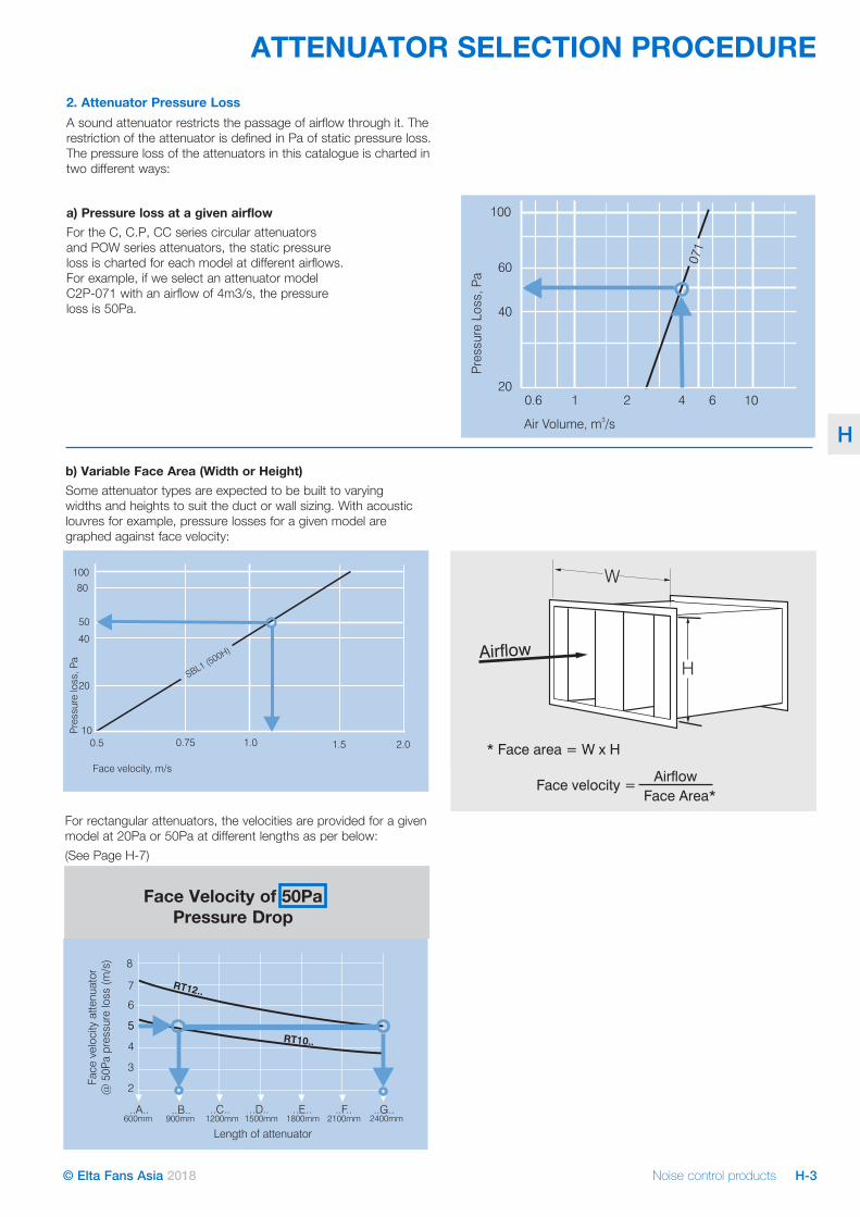
ATTENUATOR SELECTION PROCEDURE2. Attenuator Pressure LossA sound attenuator restricts the passage of airflow through it. The restriction of the attenuator is defined in Pa of static pressure loss. The pressure loss of the attenuators in this catalogue is charted in two different ways:
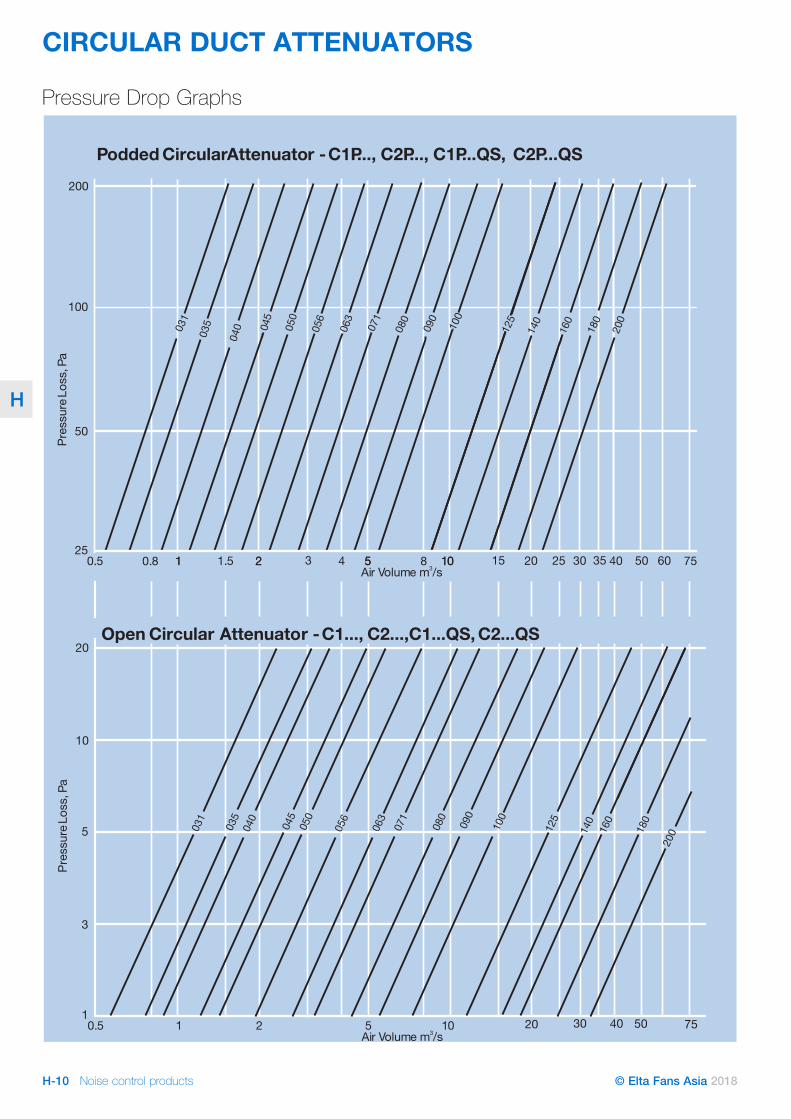
a) Pressure loss at a given airflow For the C, C.P, CC series circular attenuators and POW series attenuators, the static pressure loss is charted for each model at different airflows. For example, if we select an attenuator model C2P-071 with an airflow of 4m3/s, the pressure loss is 50Pa.
b) Variable Face Area (Width or Height)Some attenuator types are expected to be built to varying widths and heights to suit the duct or wall sizing. With acoustic louvres for example, pressure losses for a given model are graphed against face velocity:
Face velocity, m/s
10
20
40
50
80
100
0.5 0.75 1.0 2.01.5
SBL1 (500H)
Pre
ssu
relo
ss,
Pa
For rectangular attenuators, the velocities are provided for a given model at 20Pa or 50Pa at different lengths as per below: (See Page H-7)
Face Velocity of 50Pa Pressure Drop
Noise control productsH-4 © Elta Fans Asia 2018
H
RECTANGULAR DUCT ATTENUATORS
Airflow
RT SeriesStandard splitters
RT..QS SeriesSplitters with infill
wrapped in impermeable film
R3T SeriesThicker splitters
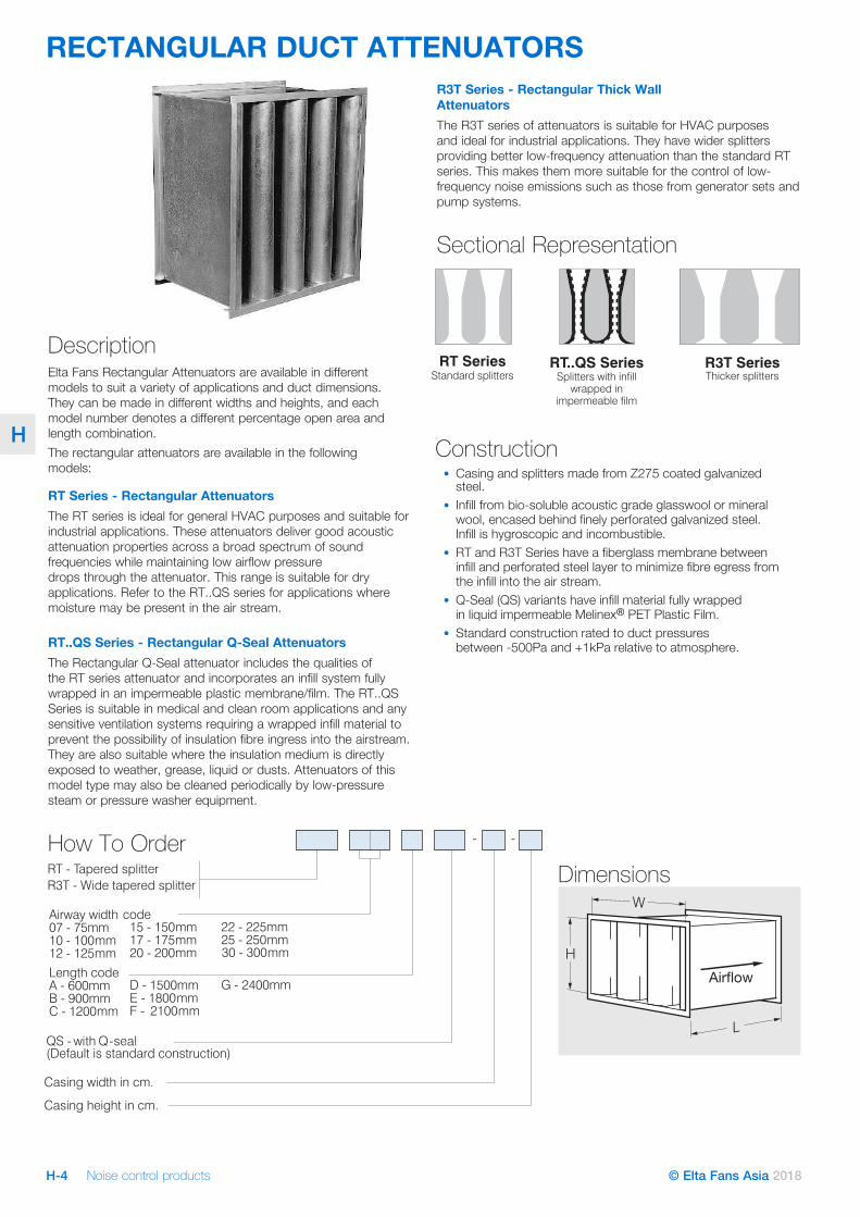
Dimensions
R3T Series - Rectangular Thick Wall AttenuatorsThe R3T series of attenuators is suitable for HVAC purposes and ideal for industrial applications. They have wider splitters providing better low-frequency attenuation than the standard RT series. This makes them more suitable for the control of low- frequency noise emissions such as those from generator sets and pump systems.
Sectional Representation
Description Elta Fans Rectangular Attenuators are available in different models to suit a variety of applications and duct dimensions. They can be made in different widths and heights, and each model number denotes a different percentage open area and length combination.The rectangular attenuators are available in the following models:
RT Series - Rectangular AttenuatorsThe RT series is ideal for general HVAC purposes and suitable for industrial applications. These attenuators deliver good acoustic attenuation properties across a broad spectrum of sound frequencies while maintaining low airflow pressure drops through the attenuator. This range is suitable for dry applications. Refer to the RT..QS series for applications where moisture may be present in the air stream.
RT..QS Series - Rectangular Q-Seal AttenuatorsThe Rectangular Q-Seal attenuator includes the qualities of the RT series attenuator and incorporates an infill system fully wrapped in an impermeable plastic membrane/film. The RT..QS Series is suitable in medical and clean room applications and any sensitive ventilation systems requiring a wrapped infill material to prevent the possibility of insulation fibre ingress into the airstream. They are also suitable where the insulation medium is directly exposed to weather, grease, liquid or dusts. Attenuators of this model type may also be cleaned periodically by low-pressure steam or pressure washer equipment.
How To Order
Construction• Casing and splitters made from Z275 coated galvanized
steel.• Infill from bio-soluble acoustic grade glasswool or mineral
wool, encased behind finely perforated galvanized steel. Infill is hygroscopic and incombustible.
• RT and R3T Series have a fiberglass membrane between infill and perforated steel layer to minimize fibre egress from the infill into the air stream.
• Q-Seal (QS) variants have infill material fully wrapped in liquid impermeable Melinex® PET Plastic Film.
• Standard construction rated to duct pressures between -500Pa and +1kPa relative to atmosphere.
Noise control products H-5© Elta Fans Asia 2018
H
RECTANGULAR DUCT ATTENUATORSSectional Sizing & Joining Flange Information
• Flanges 35mm TDF or compatible up to a maximum height or width of 1200mm. Above these sizes 40mm or 50mm steel angle section frames used, supplied undrilled.
• Matching flanges for attaching to accompanying ductwork can also be supplied.
• Rectangular attenuators will typically be made in a single piece up to a maximum of 2250mm in width, length or height. Above this dimension attenuators will be split into multiple sections in the dimension(s) exceeding the 2250mm limit noted.
• As a special request, attenuators may be divided into smaller sized sections than standard to fit through small spaces, before they are reassembled as a single unit on site.
Customised Attenuator OptionsThe following are available as special options when ordering Elta Fans rectangular attenuators:
• Different materials of construction such as Stainless Steel Grades 304 and 316.
• Paints / protective coatings such as epoxy paint, Chlorinated Rubber etc.
• Flange material/dimensions profile can be specified e.g. Ductmate, TDF, Plain Steel Angle.
• Access doors for easy cleaning (e.g. in Kitchen Exhaust Applications).
Suggested SpecificationRectangular attenuators shall be of the RT, R3T or RT..QS Series as designed and manufactured by Elta Fans and shall have the dimensions, acoustic attenuator insertion losses and pressure losses as scheduled. Acoustic Attenuator Insertion Loss data for the attenuators to be derived from tests in accordance to BS4718:1971.
The casing shall be manufactured from forming grade zinc-coated mild steel sheet with Pittsburgh corner seams.
The infill material shall be either rockwool or fibreglass as specified by the manufacturer. The infill material shall be covered with a membrane to prevent erosion of the fibres, then encased in galvanised perforated sheet metal. Where attenuators are exposed to the weather they shall be of the RT..QS Series where all infill materials shall be lined with an impervious film to prevent the ingress of moisture.
The infill material when tested in accordance with AS1530.3:1989 shall have the following indices:
Ignitability 0
Spread of flame 0
Heat evolved 0
Smoke developed 0
Noise control productsH-6 © Elta Fans Asia 2018
H
RECTANGULAR DUCT ATTENUATORS
R3T.. Series
RT.. Series
RT..QS Series
R3T.. Series
RT.. Series
RT..QS Series
R3T.. Series
RT.. Series
RT..QS Series
32 28 24 19 RT07G RT07GQS25 28 24 22 19 17 R3T15G RT10G RT10GQS22 24 22 20 17 16 R3T17G RT12G RT12GQS18 22 19 17 16 15 R3T22G RT15G RT15GQS14 19 17 15 14 13 R3T30G RT20G RT20GQS
30 26 0 21 18 RT07F RT07FQS24 26 23 19 17 16 R3T15F RT10F RT10FQS21 23 20 18 16 15 R3T17F RT12F RT12FQS17 21 18 16 15 14 R3T22F RT15F RT15FQS12 17 15 14 13 12 R3T30F RT20F RT20FQS
27 24 18 16 RT07E RT07EQS22 24 21 17 15 14 R3T15E RT10E RT10EQS19 21 19 16 14 13 R3T17E RT12E RT12EQS16 19 16 14 13 12 R3T22E RT15E RT15EQS12 16 14 12 11 11 R3T30E RT20E RT20EQS
25 22 15 14 RT07D RT07DQS20 22 19 15 13 12 R3T15D RT10D RT10DQS17 20 16 14 12 11 R3T17D RT12D RT12DQS14 18 15 12 11 11 R3T22D RT15D RT15DQS11 14 12 10 10 9 R3T30D RT20D RT20DQS
22 19 12 11 RT07C RT07CQS17 19 17 12 11 10 R3T15C RT10C RT10CQS15 17 14 11 10 9 R3T17C RT12C RT12CQS12 16 13 10 9 9 R3T22C RT15C RT15CQS9 13 11 9 8 8 R3T30C RT20C RT20CQS
18 15 10 8 RT07B RT07BQS14 16 13 10 8 7 R3T15B RT10B RT10BQS12 14 11 9 8 6 R3T17B RT12B RT12BQS10 13 10 8 7 6 R3T22B RT15B RT15BQS7 10 8 7 6 5 R3T30B RT20B RT20BQS
14 10 6 4 RT07A RT07AQS10 11 9 7 5 4 R3T15A RT10A RT10AQS9 10 8 6 5 4 R3T17A RT12A RT12AQS7 9 7 6 5 3 R3T22A RT15A RT15AQS6 7 6 5 4 3 R3T30A RT20A RT20AQS
Length mm
2400
2100
1800
1500
1200
900
600
% open area2633374350263337435026333743502633374350263337435026333743502633374350
Length(F)
2100
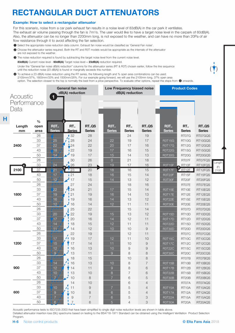
Product CodesLow Frequency biased noise dB(A) reduction
General fan noise dB(A) reduction
2
1Acoustic Performance Data
Acoustic performance tests to ISO7235-2003 that have been simplified to single digit noise reduction levels are shown in table above. Detailed attenuator insertion loss (SIL) spectrums based on testing to the BS4718-1971 Standard can be obtained using the Intelligent Ventilation Product Selection Program.
Example: How to select a rectangular attenuatorFor this scenario, noise from a car park exhaust fan results in a noise level of 83dB(A) in the car park it ventilates. The exhaust air volume passing through the fan is 7m3/s. The user would like to have a target noise level in the carpark of 60dB(A). Also, the attenuator can be no longer than 2200mm long, is not exposed to the weather, and can have no more than 20Pa of air flow resistance through it to avoid affecting the fan selection. 1 Select the appropriate noise reduction data column. Exhaust fan noise would be classified as ‘General Fan noise’.2 Choose the attenuator series required. Both the RT and R3T models would be appropriate as the internals of the attenuator
are not exposed to the weather.3 The noise reduction required is found by subtracting the target noise level from the current noise level.
83dB(A) Current noise level - 60dB(A) Target noise level = 23dB(A) reduction required. Under the “General fan noise dB(A) reduction” columns for the attenuator series (RT & R3T) chosen earlier, follow the line sequence until the reduction noise (23 dB(A)) is found or marginally exceeds this number.
4 To achieve a 23 dB(A) noise reduction using the RT series, the following length and % open area combinations can be used; 2100mm/37%, 1800mm/33% and 1500mm/26%. For our example going forward, we will use the 2100mm long, 37% open area option. The selection closest to the top is normally the best from a price perspective. To evaluate other options, repeat the steps from 4 onwards.
5
( )
34
Noise control products H-7© Elta Fans Asia 2018
H
RECTANGULAR DUCT ATTENUATORS
0
2
4
6
8
10
12
600 900 1200 1500 1800 2100 2400
Length of silencer (mm)Face
velo
city
sile
ncer
@50
Papr
essu
relo
ss(m
/s)
RT20 Series
RT15 SeriesRT12 Series
RT10 SeriesRT07 Series
RT and RT..QS Series Silencers -Face Velocity at 50Pa Pressure Loss
0
1
2
3
4
5
6
900 1200 1500 1800 2100 2400
RS15 Series
RS12 SeriesRS10 Series
RS07 Series
RS Series SilencersFace Velocity at 50Pa Pressure Loss
Face
velo
city
sile
ncer
@50
Papr
essu
relo
ss(m
/s)
Length of silencer (mm)
0
1
2
3
4
5
6
7
8
9
10
600 900 1200 1500 1800 2100 2400
R3T15 Series
R3T17 Series
R3T22 Series
R3T30 Series
R3T Series SilencersFace Velocity at 50Pa Pressure Loss
Length of silencer (mm)Face
velo
city
sile
ncer
@50
Papr
essu
relo
ss(m
/s)
Face Velocity at Pressure Loss20Pa Face Velocity at Pressure Loss50Pa
1
2
3
4
5
6
7
600mm 900mm 1200mm
1
2
3
4
5
6
7
Length of silencer*
R3T Series
R3T30..
R3T22..
R3T17..R3T15..
..A.. ..B.. ..C.. ..D.. ..E.. ..F.. ..G..
Face
velo
city
sile
ncer
@50
Papr
essu
r elo
ss(m
/s)
Face
velo
city
sile
ncer
@20
Papr
essu
relo
ss(m
/s)
R3T30..
R3T22..
R3T17..R3T15..
1500mm 1800mm 2100mm 2400mm 600mm 900mm 1200mm
Length of silencer*
..A.. ..B.. ..C.. ..D.. ..E.. ..F.. ..G..1500mm 1800mm 2100mm 2400mm
1
2
3
4
5
6
7
Face
velo
city
sile
n ce r
@50
P apr
essu
relo
ss(m
/s)
1
2
3
4
5
6
7RS Series
RS15..
RS10..RS12..
RS07..
Face
velo
city
sile
ncer
@20
P apr
essu
relo
ss(m
/s)
RS15..
RS10..RS12..
RS07..
600mm 900mm 1200mm
Length of silencer*
..A.. ..B.. ..C.. ..D.. ..E.. ..F.. ..G..1500mm 1800mm 2100mm 2400mm 600mm 900mm 1200mm
Length of silencer*
..A.. ..B.. ..C.. ..D.. ..E.. ..F.. ..G..1500mm 1800mm 2100mm 2400mm
1
2
3
4
5
6
7
1
2
3
4
5
6
7
RT20../QS..
RT15../QS..RT12../QS..
RT10../QS..
RT07../QS..
RT and RT..QS
RT20..
RT15..
RT12..
RT10..
RT07..
Face
velo
city
sile
ncer
@50
P apr
essu
relo
ss(m
/s)
Face
velo
city
sile
ncer
@20
P apr
essu
relo
ss(m
/s)
600mm 900mm 1200mm
Length of silencer*
..A.. ..B.. ..C.. ..D.. ..E.. ..F.. ..G..1500mm 1800mm 2100mm 2400mm600mm 900mm 1200mm
Length of silencer*
..A.. ..B.. ..C.. ..D.. ..E.. ..F.. ..G..1500mm 1800mm 2100mm 2400mm
Face Velocity at Pressure20Pa
1
2
3
4
5
6
7
600mm 900mm 1200mm
1
2
3
4
5
6
7
Length of silencer*
R3TSeries
..A.. ..B.. ..C.. ..D.. ..E.. ..F.. ..G..
Face
velo
city
sile
ncer
@50
Papr
essu
relo
ss(m
/s)
Face
velo
city
sile
ncer
@20
P apr
essu
relo
ss(m
/s)
1500mm 1800mm 2100mm 2400mm 600mm 900mm 1200mm
Length of silencer*
..A.. ..B.. ..C.. ..D.. ..E.. ..F.. ..G..1500mm 1800mm 2100mm 2400mm
1
2
3
4
5
6
7
Face
velo
city
sile
ncer
@50
Papr
essu
relo
ss(m
/s)
1
2
3
4
5
6
7
RSSeries
Face
velo
city
sile
ncer
@20
P apr
essu
relo
ss(m
/s)
600mm 900mm 1200mm
Length of silencer*
..A.. ..B.. ..C.. ..D.. ..E.. ..F.. ..G..1500mm 1800mm 2100mm 2400mm 600mm 900mm 1200mm
Length of silencer*
..A.. ..B.. ..C.. ..D.. ..E.. ..F.. ..G..1500mm 1800mm 2100mm 2400mm
1
2
3
4
5
6
7
1
2
3
4
5
6
7
RT&
RT..QSSeries
Face
velo
city
s ile
ncer
@50
P apr
essu
relo
ss(m
/s)
Face
velo
city
sile
ncer
@20
P apr
essu
relo
ss(m
/s)
600mm 900mm 1200mm
Length of silencer*
..A.. ..B.. ..C.. ..D.. ..E.. ..F.. ..G..1500mm 1800mm 2100mm 2400mm600mm 900mm 1200mm
Length of silencer*
..A.. ..B.. ..C.. ..D.. ..E.. ..F.. ..G..1500mm 1800mm 2100mm 2400mm
RS15..
RS10..RS12..
RS07..
RS15..
RS10..RS12..
RS07..
R3T30..
R3T22..
R3T17..R3T15..
RT20../QS..
RT15../QS..RT12../QS..
RT10../QS..
R3T30..
R3T22..
R3T17..R3T15..
Face Velocity at Pressure50Pa
Face Velocity at 20Pa Pressure Face Velocity at 50Pa Pressure
RT20../QS..
RT15../QS..RT12../QS..
RT10../QS..RT07../QS..RT07../QS..
Face Velocity at Pressure Drop20Pa
1
2
3
4
5
6
600mm 900mm 1200mm
1
2
3
4
5
6
Length of attenuator
..A.. ..B.. ..C.. ..D.. ..E.. ..F.. ..G..
Face
velo
city
sile
ncer
@50
Papr
essu
relo
ss(m
/s)
1500mm 1800mm 2100mm 2400mm
600mm 900mm 1200mm
Length of silencer*
..A.. ..B.. ..C.. ..D.. ..E.. ..F.. ..G..1500mm 1800mm 2100mm 2400mm
1
2
3
4
5
6
7
2
4
6
8
10
12
11
RT.. Series & RT.. QS Series
Face
velo
cit y
sile
ncer
@50
Pap r
essu
relo
ss(m
/s)
Atte
nuat
orfa
ceve
loci
ty@
20Pa
pres
sure
loss
(m/s
)
600mm 900mm 1200mm
Length of silencer*
..A.. ..B.. ..C.. ..D.. ..E.. ..F.. ..G..1500mm 1800mm 2100mm 2400mm
600mm 900mm 1200mm
Length of attenuator
..A.. ..B.. ..C.. ..D.. ..E.. ..F.. ..G..1500mm 1800mm 2100mm 2400mm
R3T30..
R3T22..
R3T17..R3T15..
RT20../QS..
RT15../QS..RT12../QS..
RT10../QS..
R3T30..
R3T22..
R3T17..R3T15..
Face Velocity at Pressure50Pa
RT20../QS..
RT15../QS..RT12../QS..
RT10../QS..
RT07../QS..
RT07../QS..
R3T.. Series
RT.. Series & RT.. QS Series
#
&
'
!
$
)
(
%"
%%
!"" ("" %#"" %'"" %)"" #%"" #&""
) !
"
#$%%&) '
"$
%"
%#
%'
#"
#
&
'
!
$
)
(
%"
%%
!"" ("" %#"" %'"" %)"" #%"" #&""
) !
"
#$%%&) '
"$
%"
%#
%'
#"
11
10
9
8
7
6
55
4
3
2
600mm 900mm 1200mm..A.. ..B.. ..C.. ..D.. ..E.. ..F.. ..G..
1500mm 1800mm 2100mm 2400mm
600mm 900mm 1200mm
Length of silencer*
..A.. ..B.. ..C.. ..D.. ..E.. ..F.. ..G..1500mm 1800mm 2100mm 2400mm600mm 900mm 1200mm
..A.. ..B.. ..C.. ..D.. ..E.. ..F.. ..G..1500mm 1800mm 2100mm 2400mm
RT20../QS..
RT15../QS..RT12../QS..
RT10../QS..
RT07../QS..
Face
velo
city
sile
ncer
@50
Papr
essu
relo
ss(m
/s)
11
10
9
8
7
6
55
4
3
2
600mm 900mm 1200mm
Length of silencer*
..A.. ..B.. ..C.. ..D.. ..E.. ..F.. ..G..1500mm 1800mm 2100mm 2400mm600mm 900mm 1200mm
..A.. ..B.. ..C.. ..D.. ..E.. ..F.. ..G..1500mm 1800mm 2100mm 2400mm
Face
velo
city
sile
ncer
@50
Papr
essu
relo
ss(m
/s) R3T30..
R3T22..
R3T17..R3T15..
Face Velocity at Pressure Drop50Pa
11
10
9
8
7
6
55
4
3
2
600mm 900mm 1200mm
Length of attenuator
..A.. ..B.. ..C.. ..D.. ..E.. ..F.. ..G..1500mm 1800mm 2100mm 2400mm
RT20../QS..
RT15../QS..RT12../QS..
RT10../QS..
RT07../QS..
Atte
nuat
orfa
ceve
loci
ty@
50Pa
pres
sure
loss
(m/s
)
9
8
7
6
55
4
3
2
600mm 900mm 1200mm
Length of attenuator
..A.. ..B.. ..C.. ..D.. ..E.. ..F.. ..G..1500mm 1800mm 2100mm 2400mm600mm 900mm 1200mm
..A.. ..B.. ..C.. ..D.. ..E.. ..F.. ..G..1500mm 1800mm 2100mm 2400mm
Atte
nuat
orfa
ceve
loci
ty@
50Pa
pres
sure
loss
(m/s
)
R3T30..
R3T22..
R3T17..
R3T15..
RT.. Series & RT.. QS Series
R3T.. SeriesR3T.. Series
Atte
nuat
orfa
ceve
loci
ty@
20Pa
pres
sure
loss
(m/s
)
3.3
R3T15.. R3T17.. R3T22.. R3T30.. RT07.. RT10.. RT12.. RT15.. RT20.. RT07..
QS RT10..
QS RT12..
QS RT15..
QS RT20..
QS
450900135018002250
475950142519002375
525105015752100
600120018002400
27555082511001375165019252200
30060090012001500180021002400
325650975
1300162519502275
3507001050140017502100
4008001200160020002400
27555082511001375165019252200
30060090012001500180021002400
3256509751300162519502275
3507001050140017502100
4008001200160020002400
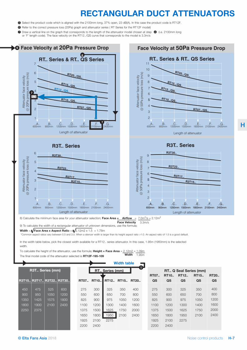
R3T.. Series (mm) RT.. Series (mm) RT.. Q Seal Series (mm)
0
2
4
6
8
10
12
600 900 1200 1500 1800 2100 2400
Length of silencer (mm)Face
velo
city
sile
ncer
@50
Papr
essu
relo
ss(m
/s)
RT20 Series
RT15 SeriesRT12 Series
RT10 SeriesRT07 Series
RT and RT..QS Series Silencers -Face Velocity at 50Pa Pressure Loss
0
1
2
3
4
5
6
900 1200 1500 1800 2100 2400
RS15 Series
RS12 SeriesRS10 Series
RS07 Series
RS Series SilencersFace Velocity at 50Pa Pressure Loss
Face
velo
city
sile
ncer
@50
Papr
essu
relo
ss(m
/s)
Length of silencer (mm)
0
1
2
3
4
5
6
7
8
9
10
600 900 1200 1500 1800 2100 2400
R3T15 Series
R3T17 Series
R3T22 Series
R3T30 Series
R3T Series SilencersFace Velocity at 50Pa Pressure Loss
Length of silencer (mm)Face
velo
city
sile
ncer
@50
P apr
essu
relo
ss(m
/s)
Face Velocity at Pressure Loss20Pa Face Velocity at Pressure Loss50Pa
1
2
3
4
5
6
7
600mm 900mm 1200mm
1
2
3
4
5
6
7
Length of silencer*
R3T Series
R3T30..
R3T22..
R3T17..R3T15..
..A.. ..B.. ..C.. ..D.. ..E.. ..F.. ..G..
Face
velo
city
sile
ncer
@50
Papr
essu
r elo
ss(m
/s)
Face
velo
city
sile
ncer
@20
Papr
essu
relo
ss(m
/s)
R3T30..
R3T22..
R3T17..R3T15..
1500mm 1800mm 2100mm 2400mm 600mm 900mm 1200mm
Length of silencer*
..A.. ..B.. ..C.. ..D.. ..E.. ..F.. ..G..1500mm 1800mm 2100mm 2400mm
1
2
3
4
5
6
7
Face
velo
city
sile
n ce r
@50
P apr
essu
relo
ss(m
/s)
1
2
3
4
5
6
7RS Series
RS15..
RS10..RS12..
RS07..
Face
velo
city
sile
ncer
@20
P apr
essu
relo
ss(m
/s)
RS15..
RS10..RS12..
RS07..
600mm 900mm 1200mm
Length of silencer*
..A.. ..B.. ..C.. ..D.. ..E.. ..F.. ..G..1500mm 1800mm 2100mm 2400mm 600mm 900mm 1200mm
Length of silencer*
..A.. ..B.. ..C.. ..D.. ..E.. ..F.. ..G..1500mm 1800mm 2100mm 2400mm
1
2
3
4
5
6
7
1
2
3
4
5
6
7
RT20../QS..
RT15../QS..RT12../QS..
RT10../QS..
RT07../QS..
RT and RT..QS
RT20..
RT15..
RT12..
RT10..
RT07..
Face
velo
city
sile
ncer
@50
P apr
essu
relo
ss(m
/s)
Face
velo
city
sile
ncer
@20
P apr
essu
relo
ss(m
/s)
600mm 900mm 1200mm
Length of silencer*
..A.. ..B.. ..C.. ..D.. ..E.. ..F.. ..G..1500mm 1800mm 2100mm 2400mm600mm 900mm 1200mm
Length of silencer*
..A.. ..B.. ..C.. ..D.. ..E.. ..F.. ..G..1500mm 1800mm 2100mm 2400mm
Face Velocity at Pressure20Pa
1
2
3
4
5
6
7
600mm 900mm 1200mm
1
2
3
4
5
6
7
Length of silencer*
R3TSeries
..A.. ..B.. ..C.. ..D.. ..E.. ..F.. ..G..
Face
velo
city
sile
ncer
@50
Papr
essu
relo
ss(m
/s)
Face
velo
city
sile
ncer
@20
P apr
essu
relo
ss(m
/s)
1500mm 1800mm 2100mm 2400mm 600mm 900mm 1200mm
Length of silencer*
..A.. ..B.. ..C.. ..D.. ..E.. ..F.. ..G..1500mm 1800mm 2100mm 2400mm
1
2
3
4
5
6
7
Face
velo
city
sile
ncer
@50
Papr
essu
relo
ss(m
/s)
1
2
3
4
5
6
7
RSSeries
Face
velo
city
sile
ncer
@20
P apr
essu
relo
ss(m
/s)
600mm 900mm 1200mm
Length of silencer*
..A.. ..B.. ..C.. ..D.. ..E.. ..F.. ..G..1500mm 1800mm 2100mm 2400mm 600mm 900mm 1200mm
Length of silencer*
..A.. ..B.. ..C.. ..D.. ..E.. ..F.. ..G..1500mm 1800mm 2100mm 2400mm
1
2
3
4
5
6
7
1
2
3
4
5
6
7
RT&
RT..QSSeries
Face
velo
city
s ile
ncer
@50
P apr
essu
relo
ss(m
/s)
Face
velo
city
sile
ncer
@20
P apr
essu
relo
ss(m
/s)
600mm 900mm 1200mm
Length of silencer*
..A.. ..B.. ..C.. ..D.. ..E.. ..F.. ..G..1500mm 1800mm 2100mm 2400mm600mm 900mm 1200mm
Length of silencer*
..A.. ..B.. ..C.. ..D.. ..E.. ..F.. ..G..1500mm 1800mm 2100mm 2400mm
RS15..
RS10..RS12..
RS07..
RS15..
RS10..RS12..
RS07..
R3T30..
R3T22..
R3T17..R3T15..
RT20../QS..
RT15../QS..RT12../QS..
RT10../QS..
R3T30..
R3T22..
R3T17..R3T15..
Face Velocity at Pressure50Pa
Face Velocity at 20Pa Pressure Face Velocity at 50Pa Pressure
RT20../QS..
RT15../QS..RT12../QS..
RT10../QS..RT07../QS..RT07../QS..
Face Velocity at Pressure Drop20Pa
1
2
3
4
5
6
600mm 900mm 1200mm
1
2
3
4
5
6
Length of attenuator
..A.. ..B.. ..C.. ..D.. ..E.. ..F.. ..G..
Face
velo
city
sile
ncer
@50
Papr
essu
relo
ss(m
/s)
1500mm 1800mm 2100mm 2400mm
600mm 900mm 1200mm
Length of silencer*
..A.. ..B.. ..C.. ..D.. ..E.. ..F.. ..G..1500mm 1800mm 2100mm 2400mm
1
2
3
4
5
6
7
2
4
6
8
10
12
11
RT.. Series & RT.. QS Series
Face
velo
cit y
sile
ncer
@50
Pap r
essu
relo
ss(m
/s)
Atte
nuat
orfa
ceve
loci
ty@
20Pa
pres
sure
loss
(m/s
)
600mm 900mm 1200mm
Length of silencer*
..A.. ..B.. ..C.. ..D.. ..E.. ..F.. ..G..1500mm 1800mm 2100mm 2400mm
600mm 900mm 1200mm
Length of attenuator
..A.. ..B.. ..C.. ..D.. ..E.. ..F.. ..G..1500mm 1800mm 2100mm 2400mm
R3T30..
R3T22..
R3T17..R3T15..
RT20../QS..
RT15../QS..RT12../QS..
RT10../QS..
R3T30..
R3T22..
R3T17..R3T15..
Face Velocity at Pressure50Pa
RT20../QS..
RT15../QS..RT12../QS..
RT10../QS..
RT07../QS..
RT07../QS..
R3T.. Series
RT.. Series & RT.. QS Series
#
&
'
!
$
)
(
%"
%%
!"" ("" %#"" %'"" %)"" #%"" #&""
) !
"
#$%%&) '
"$
%"
%#
%'
#"
#
&
'
!
$
)
(
%"
%%
!"" ("" %#"" %'"" %)"" #%"" #&""
) !
"
#$%%&) '
"$
%"
%#
%'
#"
11
10
9
8
7
6
55
4
3
2
600mm 900mm 1200mm..A.. ..B.. ..C.. ..D.. ..E.. ..F.. ..G..
1500mm 1800mm 2100mm 2400mm
600mm 900mm 1200mm
Length of silencer*
..A.. ..B.. ..C.. ..D.. ..E.. ..F.. ..G..1500mm 1800mm 2100mm 2400mm600mm 900mm 1200mm
..A.. ..B.. ..C.. ..D.. ..E.. ..F.. ..G..1500mm 1800mm 2100mm 2400mm
RT20../QS..
RT15../QS..RT12../QS..
RT10../QS..
RT07../QS..
Face
velo
city
sile
ncer
@50
Papr
essu
relo
ss(m
/s)
11
10
9
8
7
6
55
4
3
2
600mm 900mm 1200mm
Length of silencer*
..A.. ..B.. ..C.. ..D.. ..E.. ..F.. ..G..1500mm 1800mm 2100mm 2400mm600mm 900mm 1200mm
..A.. ..B.. ..C.. ..D.. ..E.. ..F.. ..G..1500mm 1800mm 2100mm 2400mm
Face
velo
city
sile
ncer
@50
Papr
essu
relo
ss(m
/s) R3T30..
R3T22..
R3T17..R3T15..
Face Velocity at Pressure Drop50Pa
11
10
9
8
7
6
55
4
3
2
600mm 900mm 1200mm
Length of attenuator
..A.. ..B.. ..C.. ..D.. ..E.. ..F.. ..G..1500mm 1800mm 2100mm 2400mm
RT20../QS..
RT15../QS..RT12../QS..
RT10../QS..
RT07../QS..
Atte
nuat
orfa
ceve
loci
ty@
50Pa
pres
sure
loss
(m/s
)
9
8
7
6
55
4
3
2
600mm 900mm 1200mm
Length of attenuator
..A.. ..B.. ..C.. ..D.. ..E.. ..F.. ..G..1500mm 1800mm 2100mm 2400mm600mm 900mm 1200mm
..A.. ..B.. ..C.. ..D.. ..E.. ..F.. ..G..1500mm 1800mm 2100mm 2400mm
Atte
nuat
orfa
ceve
loci
ty@
50Pa
pres
sure
loss
(m/s
)
R3T30..
R3T22..
R3T17..
R3T15..
RT.. Series & RT.. QS Series
R3T.. SeriesR3T.. Series
Atte
nuat
orfa
ceve
loci
ty@
20Pa
pres
sure
loss
(m/s
)
Width table
6
6
7
5 Select the product code which is aligned with the 2100mm long, 37% open, 23 dB(A). In this case the product code is RT12F.6 Refer to the correct pressure loss (20Pa) graph and attenuator series ( RT Series for the RT12F model)7 Draw a vertical line on the graph that corresponds to the length of the attenuator model chosen at step 4 (i.e. 2100mm long or ‘F’ length code). The face velocity on the RT12../QS curve that corresponds to the model is 3.3m/s
Face Velocity8) Calculate the minimum face area for your attenuator selection; Face Area = Airflow = 7.0m3/s = 2.12m2
9) To calculate the width of a rectangular attenuator of unknown dimensions, use the formula;Width = Face Area x Aspect Ratio = 2.12m2 x 1.5 = 1.78m *Common aspect ratios vary between 0.5 and 3.0. When a silencer width is larger than its height aspect ratio >1.0. An aspect ratio of 1.5 is a good default. In the width table below, pick the closest width available for a RT12.. series attenuator. In this case, 1.95m (1950mm) is the selected width.To calculate the height of the attenuator, use the formula; Height = Face Area = 2.12m2 = 1.09mThe final model code of the attenuator selected is RT12F-195-109 Width 1.95m
3.3m/s
7
9
Noise control productsH-8 © Elta Fans Asia 2018
H
CIRCULAR DUCT ATTENUATORS
C Series CP Series
C1C2
C SeriesC Series C.P Serieswith Q-Seal
C.P Serieswith Q-Seal
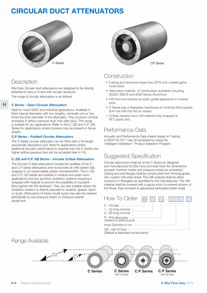
Construction• Casing and structure made from Z275 zinc coated galva-
nized steel.• Alternative material of construction available including
SS304, SS316 and 5000 Series Aluminium.• Infill from bio-soluble acoustic grade glasswool or mineral
wool. • C Series has a fiberglass membrane to minimize fibre egress
from the infill into the air stream.• Q-Seal variants have infill material fully wrapped in
PET plastic film.
Performance DataAcoustic and Performance Data sheets based on Testing to BS4718:1971 may be accessed by using the ‘Intelligent Ventilation ’ Product Selection Program.
Suggested SpecificationCircular attenuators shall be of the C Series as designed and manufactured by Elta Fans and shall have the dimensions, acoustic insertion losses and pressure losses as scheduled. Casing and end flanges shall be constructed from forming grade zinc-coated mild steel sheet. The infill material shall be either rockwool or fibreglass as specified by the manufacturer. The infill material shall be covered with a gauze scrim to prevent erosion of the fibres, then encased in galvanised perforated sheet metal.
How To Order
DescriptionElta Fans Circular duct attenuators are designed to be directly attached to fans or in-line with circular ductwork. The range of circular attenuators is as follows:
C Series - Open Circular AttenuatorsIdeal for most HVAC and industrial applications. Available in fixed internal diameters with two lengths, nominally one or two times the inner diameter of the attenuator. They produce nominal increases in airflow pressure drop over plain duct. This range is suitable for dry applications. Refer to the C..QS and C.P..QS Series for applications where moisture may be present in the air stream. C.P Series - Podded Circular Attenuators The C Series circular attenuator can be fitted with a full length acoustically absorptive pod. Ideal for applications where additional acoustic performance is required over the C Series and higher airflow pressure loss can be accepted (see H-10).
C..QS and C.P..QS Series - Circular Q-Seal AttenuatorsThe Circular Q-Seal attenuators include the qualities of the C and C.P series attenuators and incorporate an infill system fully wrapped in an impermeable plastic membrane/film. The C..QS and C.P..QS Series are suitable in medical and clean room applications and any sensitive ventilation systems requiring a wrapped infill material to prevent the possibility of insulation fibre ingress into the airstream. They are also suitable where the insulation medium is directly exposed to weather, grease, liquid or dusts. Attenuators of these model types may also be cleaned periodically by low-pressure steam or pressure washer equipment.
Range Available
Noise control products H-9© Elta Fans Asia 2018
H
CIRCULAR DUCT ATTENUATORS
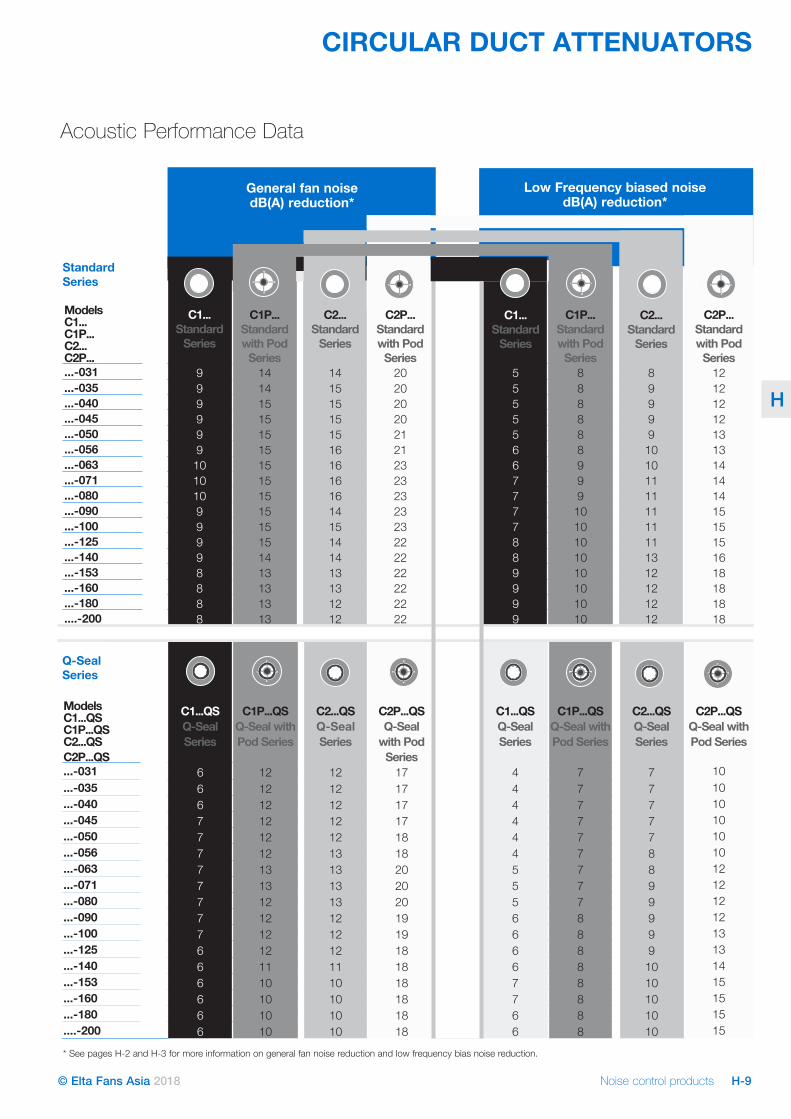
Acoustic Performance Data
Models C1...QSC1P...QS C2...QSC2P...QS
C1...QSQ-Seal Series
C1P...QSQ-Seal with Pod Series
C2...QS Q-Seal Series
C2P...QSQ-Seal
with Pod Series
C1...QSQ-Seal Series
C1P...QSQ-Seal with Pod Series
C2...QSQ-SealSeries
C2P...QSQ-Seal with Pod Series
...-031 6 12 12 17 4 7 7 10
...-035 6 12 12 17 4 7 7 10
...-040 6 12 12 17 4 7 7 10
...-045 7 12 12 17 4 7 7 10
...-050 7 12 12 18 4 7 7 10
...-056 7 12 13 18 4 7 8 10
...-063 7 13 13 20 5 7 8 12
...-071 7 13 13 20 5 7 9 12
...-080 7 12 13 20 5 7 9 12
...-090 7 12 12 19 6 8 9 12
...-100 7 12 12 19 6 8 9 13
...-125 6 12 12 18 6 8 9 13
...-140 6 11 11 18 6 8 10 14
...-153 6 10 10 18 7 8 10 15
...-160 6 10 10 18 7 8 10 15
...-180 6 10 10 18 6 8 10 15
....-200 6 10 10 18 6 8 10 15
Low Frequency biased noise dB(A) reduction*
Models C1... C1P... C2... C2P...
St
C1...Standard
Series
C1P...Standard with Pod
Series
C2...Standard
Series
C2P...Standard with Pod
Series
C1...Standard
Series
C1P...Standard with Pod
Series
C2...Standard
Series
C2P...Standard with Pod
Series...-031 9 14 14 20 5 8 8 12...-035 9 14 15 20 5 8 9 12...-040 9 15 15 20 5 8 9 12...-045 9 15 15 20 5 8 9 12...-050 9 15 15 21 5 8 9 13...-056 9 15 16 21 6 8 10 13...-063 10 15 16 23 6 9 10 14...-071 10 15 16 23 7 9 11 14...-080 10 15 16 23 7 9 11 14...-090 9 15 14 23 7 10 11 15...-100 9 15 15 23 7 10 11 15...-125 9 15 14 22 8 10 11 15...-140 9 14 14 22 8 10 13 16...-153 8 13 13 22 9 10 12 18...-160 8 13 13 22 9 10 12 18...-180 8 13 12 22 9 10 12 18....-200 8 13 12 22 9 10 12 18
General fan noise dB(A) reduction*
Standard Series
Q-Seal Series
* See pages H-2 and H-3 for more information on general fan noise reduction and low frequency bias noise reduction.
Noise control productsH-10 © Elta Fans Asia 2018
H
Pressure Drop Graphs
CIRCULAR DUCT ATTENUATORS
200
251 2 5 10 200.5
100
50
1 2 5 10 40 60 75Air Volume m /s3
Pres
sure
Loss
,Pa
031
035
040 04
5
050
056
071
100
125
140
160
200
080
Podded CircularAttenuator -C1P..., C2P..., C1P...QS, C2P...QS
035
045
050
063
071
090
20
10
5
3
11 2 5 10 20 40 50 750.5 30
Air Volume m /s3
Pres
sure
Loss
,Pa
100
080
Open Circular Attenuator -C1..., C2...,C1...QS, C2...QS
090
063
180
0.8 1.5 3 4 8 15 25 3530 50
160
125
140
180
20005
6
040
031
Noise control products H-11© Elta Fans Asia 2018
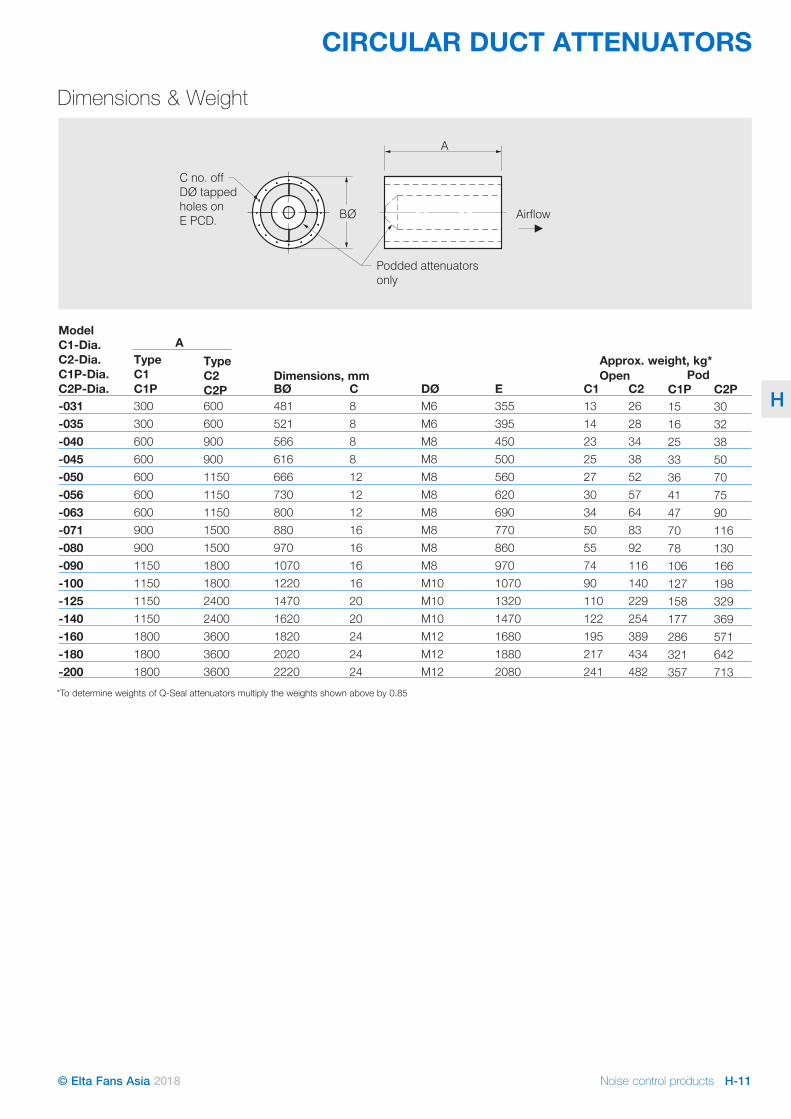
H
A
BØ
C no. off
DØ tapped
holes on
E PCD.
Podded attenuators
only
Airflow
Model C1-Dia. C2-Dia. C1P-Dia. C2P-Dia.
Type C1 C1P
Type C2 C2P BØ C DØ E C1 C2 C1P C2P
-031 300 600 481 8 M6 355 13 26 15 30-035 300 600 521 8 M6 395 14 28 16 32-040 600 900 566 8 M8 450 23 34 25 38-045 600 616 8 M8 500 25 38 33 50-050 600 1150 666 12 M8 560 27 52 36 70-056 600 1150 730 12 M8 620 30 57 41 75-063 600 1150 800 12 M8 690 34 64 47 90-071 900 1500 880 16 M8 770 50 83 70 116-080 900 1500 970 16 M8 860 55 92 78 130-090 1150 1800 1070 16 M8 970 74 116 106 166-100 1150 1800 1220 16 M10 1070 90 140 127 198-125 1150 2400 1470 20 M10 1320 110 229 158 329-140 1150 2400 1620 20 M10 1470 122 254 177 369-160 1800 3600 1820 24 M12 1680 195 389 286 571-180 1800 3600 2020 24 M12 1880 217 434 321 642-200 1800 3600 2220 24 M12 2080 241 482 357 713
A
Dimensions, mmApprox. weight, kg*Open Pod
Dimensions & Weight
*To determine weights of Q-Seal attenuators multiply the weights shown above by 0.85
CIRCULAR DUCT ATTENUATORS
900
Noise control productsH-12 © Elta Fans Asia 2018
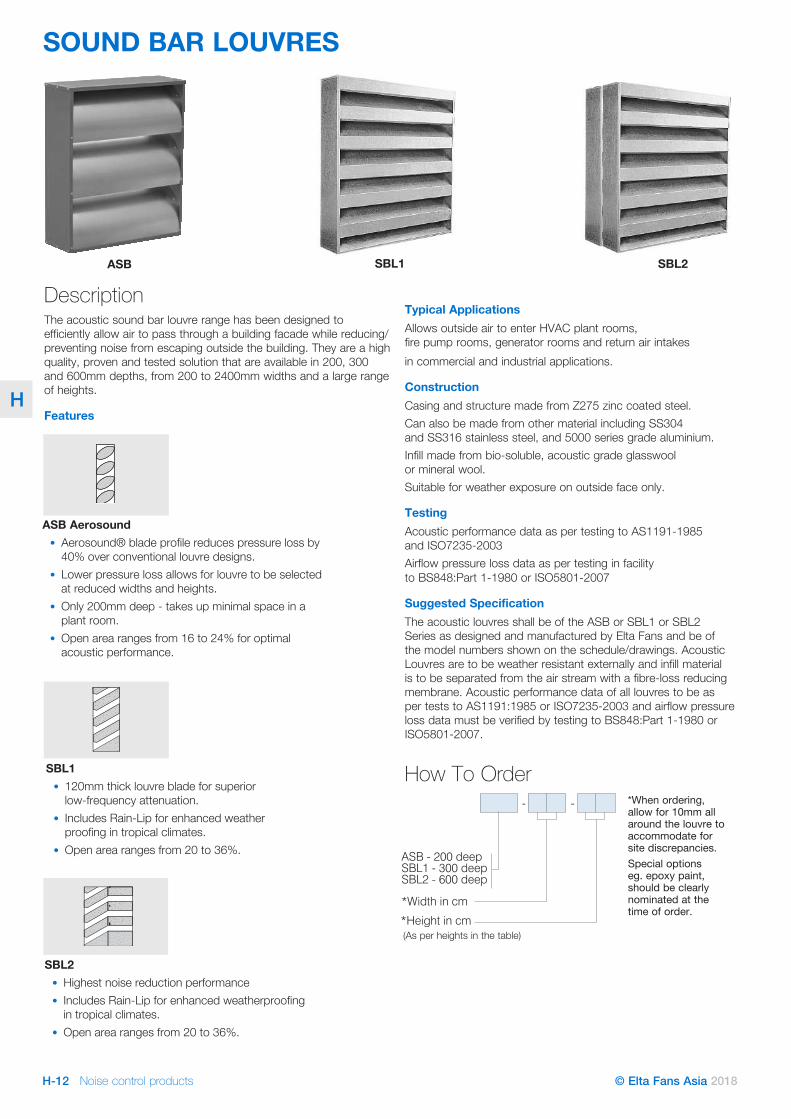
H
SOUND BAR LOUVRES
DescriptionThe acoustic sound bar louvre range has been designed to efficiently allow air to pass through a building facade while reducing/preventing noise from escaping outside the building. They are a high quality, proven and tested solution that are available in 200, 300 and 600mm depths, from 200 to 2400mm widths and a large range of heights.
Features
SBL1ASB SBL2
Typical ApplicationsAllows outside air to enter HVAC plant rooms, fire pump rooms, generator rooms and return air intakes in commercial and industrial applications.
ConstructionCasing and structure made from Z275 zinc coated steel.Can also be made from other material including SS304 and SS316 stainless steel, and 5000 series grade aluminium.Infill made from bio-soluble, acoustic grade glasswool or mineral wool. Suitable for weather exposure on outside face only.
TestingAcoustic performance data as per testing to AS1191-1985 and ISO7235-2003Airflow pressure loss data as per testing in facility to BS848:Part 1-1980 or ISO5801-2007
Suggested SpecificationThe acoustic louvres shall be of the ASB or SBL1 or SBL2 Series as designed and manufactured by Elta Fans and be of the model numbers shown on the schedule/drawings. Acoustic Louvres are to be weather resistant externally and infill material is to be separated from the air stream with a fibre-loss reducing membrane. Acoustic performance data of all louvres to be as per tests to AS1191:1985 or ISO7235-2003 and airflow pressure loss data must be verified by testing to BS848:Part 1-1980 or ISO5801-2007.
How To OrderSBL1 • 120mm thick louvre blade for superior
low-frequency attenuation.• Includes Rain-Lip for enhanced weather
proofing in tropical climates.• Open area ranges from 20 to 36%.
SBL2• Highest noise reduction performance• Includes Rain-Lip for enhanced weatherproofing
in tropical climates.• Open area ranges from 20 to 36%.
*When ordering, allow for 10mm all around the louvre to accommodate for site discrepancies.Special options eg. epoxy paint, should be clearly nominated at the time of order.
(As per heights in the table)
ASB Aerosound• Aerosound® blade profile reduces pressure loss by
40% over conventional louvre designs.• Lower pressure loss allows for louvre to be selected
at reduced widths and heights.• Only 200mm deep - takes up minimal space in a
plant room.• Open area ranges from 16 to 24% for optimal
acoustic performance.

Noise control products H-13© Elta Fans Asia 2018
H
SOUND BAR LOUVRES
Height, mm % Free Area500mm (Kg) 1000mm (Kg) 1500mm (Kg) 2000mm (Kg)500 11 19 28 36 16.0750 16 28 40 52 19.01000 21 36 52 67 20.01275 26 45 64 83 23.01525 31 53 75 98 23.01800 35 61 87 113 24.02050 40 70 99 129 24.02300 45 78 111 144 24.0
Weights
Height, mm % Free Area500mm (Kg) 1000mm (Kg) 1500mm (Kg) 2000mm Kg)500 13 23 33 43 20.0 750 20 35 50 65 26.71000 27 47 67 87 30.01250 34 59 84 109 32.01500 41 71 101 131 33.31750 48 83 118 153 34.32000 55 95 135 175 35.02250 62 107 152 197 35.6
Height, mm % Free Area500mm (Kg) 1000mm (Kg) 1500mm (Kg) 2000mm (Kg)500 24 43 61 80 20.0750 37 65 93 120 26.71000 50 87 124 161 30.0 1250 63 109 155 202 32.0 1500 76 131 187 242 33.3 1750 89 154 218 283 34.3 2000 102 176 250 324 35.0 2250 116 198 281 364 35.6
Weights(kg) for width of
Weights(kg) for width of
SBL1
SBL2
ASB Aerosound
Dimensions in mm
Dimensions
Weights(kg) for width of

Noise control productsH-14 © Elta Fans Asia 2018
H
Additional Information: For SBL2 pressure losses, multiply SBL1 losses by 1.03. For reverse airflow on SBL1 & SBL2 models, multiply pressure loss by 1.3. For ASB models, pressure loss is the same for both airflow directions.
Pressure Drop Graph
Model 63 125 250 500 1k 2k 4k 8k7 11 12 10 10 9
4 7 9 13 14 12 12 8SBL1
Acoustic PerformanceStatic Insertion Loss, dBOctave Band Centre Frequency (Hz)
STL
STL
NR
NR 10 13 15 19 20 18 18 14
9 17 18 16 16 15ASB
SBL2STL NR
General HVAC
133
7
1
5 10 14 22 27 25 21 1711 16 20 28 33 31 27 23
5.8
8.6-
-
12.7-
9.8
11.9-
-
19.9-
NR - Noise reduction STL - Sound transmission loss
Low Frequency
dB(A) Reduction*
* See ‘Attenuator Selection Procedure’ on page H2/3 for further information on dB(A) reduction.Refer to the ‘General Acoustic Information Section’ for further detail on NR and STL rating.
Additional Information: the internal design for the ASB is different to what is shown above. However,
the mounting arrangement is the same.
Mounting ArrangementsSOUND BAR LOUVRES
Noise control productsH-16 © Elta Fans Asia 2018
H
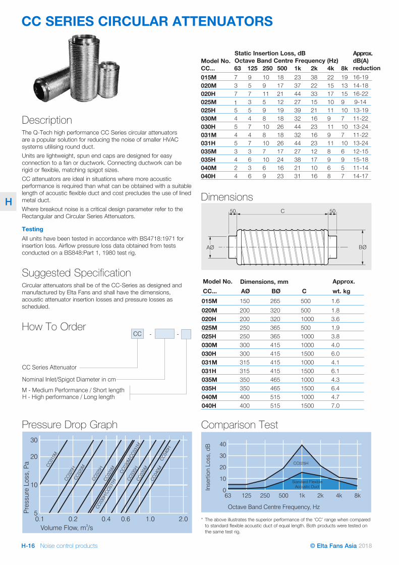
CC SERIES CIRCULAR ATTENUATORS
DescriptionThe Q-Tech high performance CC Series circular attenuators are a popular solution for reducing the noise of smaller HVAC systems utilising round duct. Units are lightweight, spun end caps are designed for easy connection to a fan or ductwork. Connecting ductwork can be rigid or flexible, matching spigot sizes.CC attenuators are ideal in situations where more acoustic performance is required than what can be obtained with a suitable length of acoustic flexible duct and cost precludes the use of lined metal duct.Where breakout noise is a critical design parameter refer to the Rectangular and Circular Series Attenuators.
Testing All units have been tested in accordance with BS4718:1971 for insertion loss. Airflow pressure loss data obtained from tests conducted on a BS848:Part 1, 1980 test rig.
Suggested Specification Circular attenuators shall be of the CC-Series as designed and manufactured by Elta Fans and shall have the dimensions, acoustic attenuator insertion losses and pressure losses as scheduled.
How To Order
C50
AØ BØ
50
* The above illustrates the superior performance of the ‘CC’ range when compared to standard flexible acoustic duct of equal length. Both products were tested on the same test rig.
12563 250 1k 2k 4k 8k5000
10
20
30
40
Octave Band Centre Frequency, Hz
Insert
ion
Lo
ss,
dB
CC025H
Standard Flexible
Acoustic Duct
Model No. CC... 63 125 250 500 1k 2k 4k 8k
020M015M
37
59
910
1718
3723
2238
1522
1319
020H 7 7 11 21 44 33 17 15025M 1 3 5 12 27 15 10 9025H 5 5 9 19 39 21 11 10030M 4 4 8 18 32 16 9 7030H 5 7 10 26 44 23 11 10031M 4 4 8 18 32 16 9 7031H 5 7 10 26 44 23 11 10035M 3 3 7 17 27 12 8 6035H 4 6 10 24 38 17 9 9040M 2 3 6 16 21 10 6 5040H 4 6 9 23 31 16 8 7
Dimensions
Comparison TestPressure Drop Graph
Model No. Approx.CC... AØ BØ C wt. kg015M 150 265 500 1.6020M 200 320 500 1.8020H 200 320 1000 3.6025M 250 365 500 1.9025H 250 365 1000 3.8030M 300 415 1000 4.0030H 300 415 1500 6.0031M 315 415 1000 4.1031H 315 415 1500 6.1035M 350 465 1000 4.3035H 350 465 1500 6.4040M 400 515 1000 4.7040H 400 515 1500 7.0
Static Insertion Loss, dBOctave Band Centre Frequency (Hz)
Approx. dB(A) reduction
14-1816-19
16-229-1413-1911-2213-2411-2213-2412-1515-1811-1414-17
Dimensions, mm
Noise control products H-17© Elta Fans Asia 2018
H
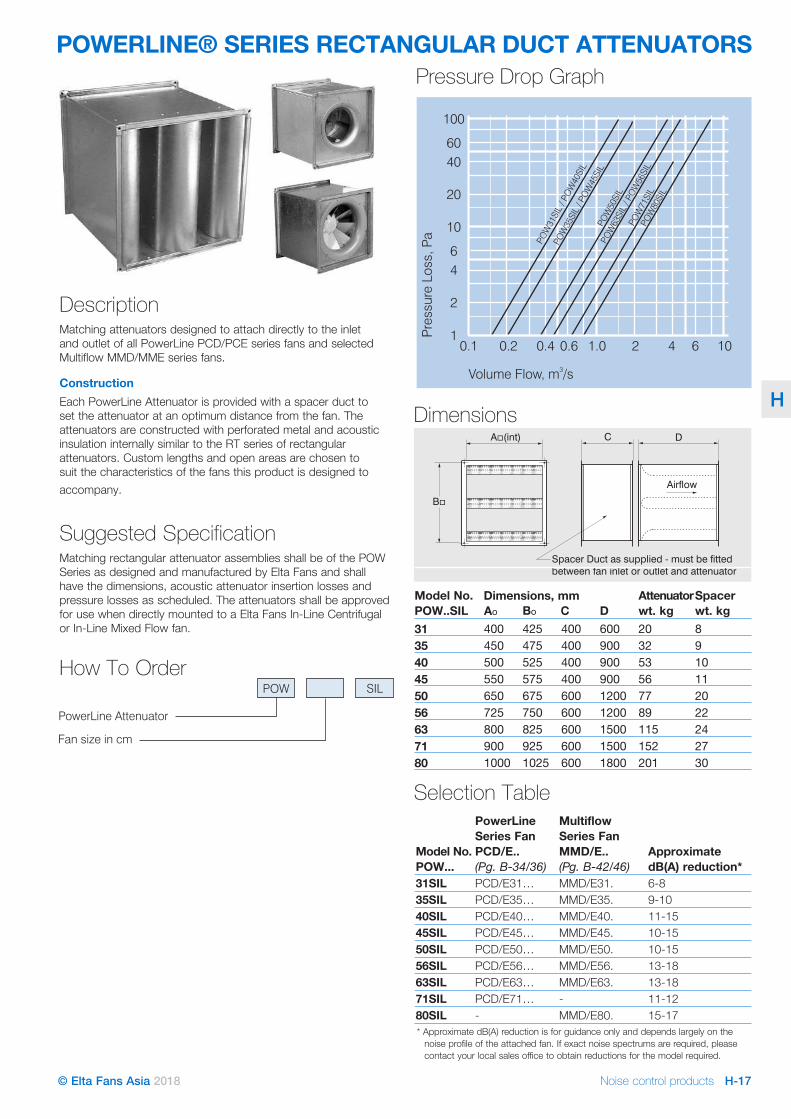
POWERLINE® SERIES RECTANGULAR DUCT ATTENUATORS
Approx. dB(A) reduction
B�
A int)�(
Spacer Duct as supplied - must be fitted
between fan inlet or outlet and attenuator
Airflow
C D
Model No. POW..SIL Ao CBo D
Spacer wt. kg
Attenuator wt. kg
31 400 400425 600 82035 450 400475 900 93240 500 400525 900 105345 550 400575 900 115650 650 600675 1200 207756 725 600750 1200 228963 800 600825 1500 2411571 900 600925 1500 2715280 1000 6001025 1800 30201
Dimensions, mm
Dimensions
Model No.POW...
PowerLine Series FanPCD/E.. (Pg. B-34/36)
Multiflow Series Fan MMD/E.. (Pg. B-42/46)
Approximate dB(A) reduction*
31SIL PCD/E31… MMD/E31. 6-835SIL PCD/E35… MMD/E35. 9-1040SIL PCD/E40… MMD/E40. 11-1545SIL PCD/E45… MMD/E45. 10-1550SIL PCD/E50… MMD/E50. 10-1556SIL PCD/E56… MMD/E56. 13-1863SIL PCD/E63… MMD/E63. 13-1871SIL PCD/E71… - 11-1280SIL - MMD/E80. 15-17
Selection Table
* Approximate dB(A) reduction is for guidance only and depends largely on the noise profile of the attached fan. If exact noise spectrums are required, please contact your local sales office to obtain reductions for the model required.
DescriptionMatching attenuators designed to attach directly to the inlet and outlet of all PowerLine PCD/PCE series fans and selected Multiflow MMD/MME series fans.
ConstructionEach PowerLine Attenuator is provided with a spacer duct to set the attenuator at an optimum distance from the fan. The attenuators are constructed with perforated metal and acoustic insulation internally similar to the RT series of rectangular attenuators. Custom lengths and open areas are chosen to suit the characteristics of the fans this product is designed to accompany.
Suggested Specification Matching rectangular attenuator assemblies shall be of the POW Series as designed and manufactured by Elta Fans and shall have the dimensions, acoustic attenuator insertion losses and pressure losses as scheduled. The attenuators shall be approved for use when directly mounted to a Elta Fans In-Line Centrifugal or In-Line Mixed Flow fan.
How To Order
0.11
4
6
10
100
60
20
40
2
0.2 0.4 0.6 1.0 2 4 6 10
PO
W31
SIL
/PO
W40
SIL
PO
W35
SIL
/PO
W45
SIL
PO
W50
SIL
PO
W80
SIL
PO
W63
SIL
/PO
W56
SIL
PO
W71
SIL
Volume Flow, m /s3
Pre
ssu
reLo
ss,P
a
Pressure Drop Graph
Noise control productsH-18 © Elta Fans Asia 2018
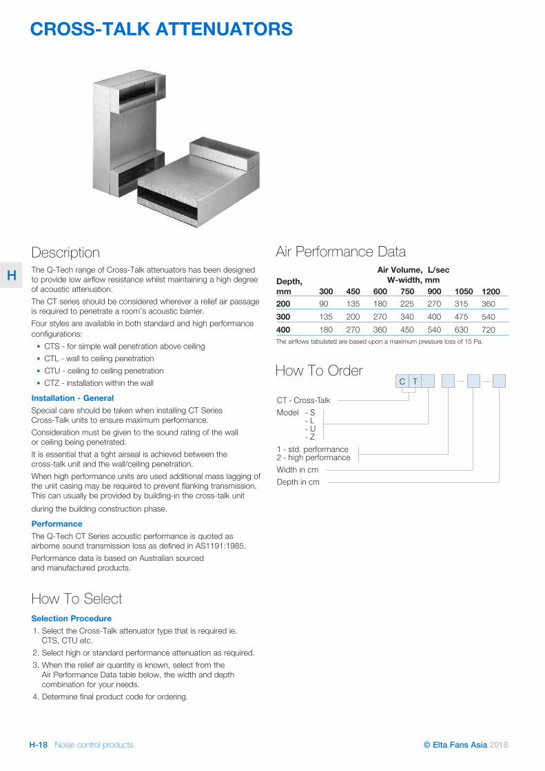
H Depth, mm 300 600 750 900 1050 1200200300400
Air Volume, L/sec W-width, mm
45090135180 270
200135 180
270360 450
340225 270
400540 630
475315 360
540720
The airflows tabulated are based upon a maximum pressure loss of 15 Pa.
CT - Cross-Talk
Model - S
1 - std. performance2 - high performance
Width in cm
Depth in cm
- L- U- Z
C T
Air Performance Data
CROSS-TALK ATTENUATORS
How To Order
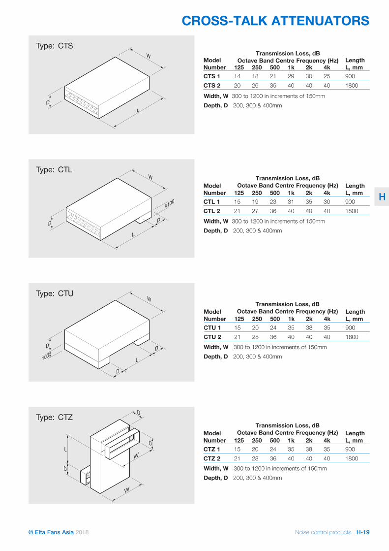
Description The Q-Tech range of Cross-Talk attenuators has been designed to provide low airflow resistance whilst maintaining a high degree of acoustic attenuation.The CT series should be considered wherever a relief air passage is required to penetrate a room’s acoustic barrier.Four styles are available in both standard and high performance configurations:
• CTS - for simple wall penetration above ceiling• CTL - wall to ceiling penetration• CTU - ceiling to ceiling penetration• CTZ - installation within the wall
Installation - GeneralSpecial care should be taken when installing CT Series Cross-Talk units to ensure maximum performance.Consideration must be given to the sound rating of the wall or ceiling being penetrated.It is essential that a tight airseal is achieved between the cross-talk unit and the wall/ceiling penetration.When high performance units are used additional mass lagging of the unit casing may be required to prevent flanking transmission. This can usually be provided by building-in the cross-talk unit during the building construction phase.
PerformanceThe Q-Tech CT Series acoustic performance is quoted as airborne sound transmission loss as defined in AS1191:1985.Performance data is based on Australian sourced and manufactured products.
How To Select Selection Procedure1. Select the Cross-Talk attenuator type that is required ie.
CTS, CTU etc.2. Select high or standard performance attenuation as required.3. When the relief air quantity is known, select from the
Air Performance Data table below, the width and depth combination for your needs.
4. Determine final product code for ordering.
Noise control products H-19© Elta Fans Asia 2018
H
L
D
D
D
100
W
W
W
D
L
D
100
D
W
W
D
DL
D
L
Type: CTS
Type: CTL
Type: CTU
Type: CTZ
CTS 2CTS 1
Length L, mm4k2k1k500250125
Model Number
14 18 21 29 30 25 9001800404040352620
Transmission Loss, dB Octave Band Centre Frequency (Hz)
Width, W 300 to 1200 in increments of 150mmDepth, D 200, 300 & 400mm
1800900
Length L, mm
CTL 2CTL 1
4k2k1k500250125Model Number
Transmission Loss, dB Octave Band Centre Frequency (Hz)
15 19 23 31 35 30404040362721
1800900
Length L, mm
CTZ 2CTZ 1
4k2k1k500250125Model Number
Width, W 300 to 1200 in increments of 150mmDepth, D 200, 300 & 400mm
Width, W 300 to 1200 in increments of 150mmDepth, D 200, 300 & 400mm
Transmission Loss, dB Octave Band Centre Frequency (Hz)
Width, W 300 to 1200 in increments of 150mmDepth, D 200, 300 & 400mm
15 20 24 35 38 35404040362821
1800900
Length L, mm
404040362821CTU 2353835242015CTU 14k2k1k500250125
Model Number
Transmission Loss, dB Octave Band Centre Frequency (Hz)
CROSS-TALK ATTENUATORS
Noise control productsH-20 © Elta Fans Asia 2018
H
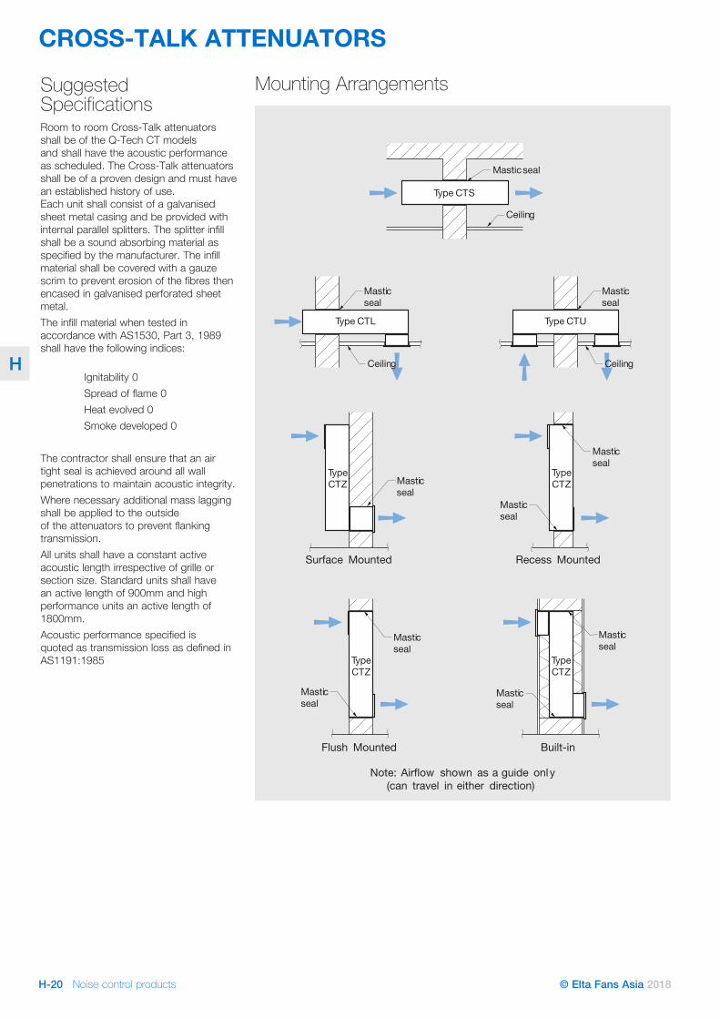
Suggested Specifications Room to room Cross-Talk attenuators shall be of the Q-Tech CT models and shall have the acoustic performance as scheduled. The Cross-Talk attenuators shall be of a proven design and must have an established history of use. Each unit shall consist of a galvanised sheet metal casing and be provided with internal parallel splitters. The splitter infill shall be a sound absorbing material as specified by the manufacturer. The infill material shall be covered with a gauze scrim to prevent erosion of the fibres then encased in galvanised perforated sheet metal. The infill material when tested in accordance with AS1530, Part 3, 1989 shall have the following indices: Ignitability 0 Spread of flame 0 Heat evolved 0 Smoke developed 0
The contractor shall ensure that an air tight seal is achieved around all wall penetrations to maintain acoustic integrity. Where necessary additional mass lagging shall be applied to the outside of the attenuators to prevent flanking transmission.All units shall have a constant active acoustic length irrespective of grille or section size. Standard units shall have an active length of 900mm and high performance units an active length of 1800mm. Acoustic performance specified is quoted as transmission loss as defined in AS1191:1985
Masticseal
Ceiling
Type CTS
Masticseal
Masticseal
Type CTUType CTL
Masticseal
Masticseal
Masticseal
TypeCTZ
TypeCTZ
Surface Mounted Recess Mounted
Masticseal
Masticseal
Masticseal
Masticseal
TypeCTZ
TypeCTZ
Flush Mounted
Note: Airflow shown as a guide only(can travel in either direction)
Built-in
Ceiling Ceiling
Mounting Arrangements
CROSS-TALK ATTENUATORS
Noise control productsH-22 © Elta Fans Asia 2018
H
GENERAL ACOUSTIC INFORMATIONIntroductionGeneral
Since 1991, Elta Group Members under the Q-Tech Acoustic Products brand have continuously invested in research and development programs. The investment in this program results in the continuous testing of new designs and materials in our own ISO7235:2003 and BS4718:1971 acoustic attenuator test rig. The results of this program include the first published test data for a range of attenuators based on Australian sourced materials and the advent of the unique Q-Seal range of specialised attenuators. Our continued investments in the research and development of acoustic products results in the most accurate and dependable data for acoustic products, unrivalled by any other supplier in the industry.Elta Group Members maintain strong relationships with universities, testing houses and the industry to ensure that the experience gained from the use of our products in the real world feeds back into the design of our new products. We will continue to be involved in the latest acoustic technology and innovation and we will continue to provide our customers with products they can rely upon. The following pages, incorporates a glossary of acoustic terms to assist the user of the Intelligent Ventilation catalogue in understanding the depth of technical information supplied for our fans and attenuators.
Sound Power LevelThe sound power is defined as the rate at which a sound source emits energy. Since sound energy in everyday situations ranges from 10-12 Watts to 1000 Watts, a logarithmic scale is used for practicality; this provides us with a sound power range from 0 to 150 dB, which is a lot more manageable.The sound power level is denoted as Lw and is defined as: and is expressed in decibels, dB Where:
W = Watts and pW = 10-12 Watts
Sound Pressure LevelThe sound pressure is what you actually hear and is the effect of the sound power in the hearing environment. It will be a function of the volume of the space, its acoustic absorption qualities and the distance of the listener from the sound source.Sound pressure level is also expressed in dB and is relative to the quietest sound which a healthy young person can hear at 1kHz; 2 x 10⁻⁵ N/m2 (or Pa).The sound pressure level, like sound power is expressed on a logarithmic scale and denoted as Lp. It is defined as:
Information On Fan Noise Test Standards
Where noted in the product data pages within this catalogue fan noise levels are tested to BS848 Part 2: 1985 “Fans for general purposes. Methods of noise testing”.
This test standard describes methods that may be applied to calculate the sound power level of fans. That is, the In-Duct method, the Reverberant Room method and the Free Field method. The sound pressure level of a product is measured using one of these test methods. A calculation is then used to convert the measured sound pressure levels to sound power levels.
Lp = 20 log10
(s , Pa)
( , 2 10 )
ound pressure
reference pressure Pa� -5
Lw = 10 log10
( , W)
( , 1 W)
sound power of source
reference power p
Noise control products H-23© Elta Fans Asia 2018
H
GENERAL ACOUSTIC INFORMATION
Typical Applications And Benefits Of Attenuator Types
Attenuator InformationStatic Insertion Losses
BS 4718 : 1971 “Methods of Test for Attenuators for Air Distribution Systems” requires manufacturers to test and publish static insertion loss figures.An insertion loss is defined as “the reduction in noise level at a given location due to the placement of an attenuator in the sound path between the sound source and that location”. A static insertion loss is the insertion loss with no airflow passing through the attenuator.Therefore placing an attenuator in between a fan and the measuring position, will reduce the noise level at the measuring position by the insertion loss.
Dynamic Insertion LossesElta Fans test attenuators to BS4718: 1971 “Methods of Test for Attenuators for Air Distribution Systems”. This test standard sets out a procedure for the testing of static insertion losses; i.e. the measuring of insertion losses without airflow.Some overseas companies publish dynamic insertion losses; that is the testing of insertion losses with airflow involved. At higher passage velocities the static insertion loss can vary from the dynamic insertion loss by a small margin, depending on the direction of the airflow compared to the noise propagation direction. For typical velocities associated with a HVAC system, the static insertion losses and dynamic insertion losses are virtually identical and can be assumed to be the same.
Airway VelocityFor a given attenuator size a higher airflow results in a higher airway passage velocity. Higher passage velocities will increase the regenerated noise level of the attenuator. This is particularly critical when the attenuator is serving a low noise level zone; i.e. film studio. A number of suggested maximum passage velocities with the appropriate room NR level are tabulated. Critical noise applications should be checked by an Acoustics Engineer.
Model Application BenefitsSmall Circular Type Attenuators
CCBathroom and Toilet exhaust fans LightweightTenancy fit outs Low costApartment fans Semi-Flexible
Circular & Rectangular Attenuators
C./C.P & RT/RS
Car park exhaust fans Circular: Easy fittingReturn Air fans Circular Open: Low pressure dropSwimming Pools Circular Pod: High performanceKitchen ExhaustsSmoke Spill fans Rectangular: High performance
Cross-talk Attenuators
CS/T/U/Z
Room to room air transfer ducts
Different designs to suit a wide range of wall/roof configurations
Police stationsOffice areas
Sound Bar Acoustic LouvresSBL1/2 ASB
Plant rooms Short lengthsWeatherproof
Critical noise level application should be checked by an acoustics engineer
Approx.NR25 Do not exceed 8 m/s In attenuator airwayNR30 “ 10 m/s “NR35 “ 13 m/s “NR40 “ 15 m/s “NR45 “ 18 m/s “

Noise control productsH-24 © Elta Fans Asia 2018
H
GENERAL ACOUSTIC INFORMATIONNoise RatingsdB(A) Levels
The ear responds not only to the absolute sound pressure level of a sound, but also to its frequency content. It actually gives a weighting to the level of sound according to its frequency content, and ascribes a certain loudness. This means that if we want to know how a person will judge the sound, we must somehow translate our objective measured units of sound pressure level and frequency content into subjective units of loudness.A sound level meter accepts all of the frequency components of a sound, and adds all their absolute levels together to give an overall sound pressure level, dB (Linear).The illustration below shows typical overall sound pressure levels produced by some everyday sources.
However the ear is not as sensitive to lower frequency sound pressure levels as it is to higher frequency sound pressure levels. In the 1930’s, experiments were carried out on 11 people by Harvey Fletcher at the Bell Telephone Laboratories in New York to determine how loud tones of different frequencies sounded subjectively. Therefore the “A” weighting (or the “A” in dB(A)) was devised so that the sound meter would filter each frequency of sound by a certain amount before adding them together to give a loudness that more closely follows the sensitivity of the human ear.
The ‘A’ frequency weighting corrections are shown below.The ‘A’ frequency weighting suggests that if a tone of 40 dB is played at 1000 Hz, a 40 dB tone played at 63 Hz would sound 26 dB quieter, or be 14 dB(A). Due to its simplicity and convenience, the ‘A’ frequency weighting has become popular and is now used for many different noise sources at different levels. In fact, most legislation regarding noise is written using dB(A)s, in addition nearly all manufacturers of fans and other noise generating machines quote their noise levels in dB(A)s at 1, 1.5, or 3 metres assuming spherical distribution. It is therefore important that we understand the ‘A’ frequency weighting and how dB(A)s are calculated.
1401301201101009080706050403020100
DECIBELSdB(A)
jet aircraft taking off (25 metres)
threshold of painDeafening
Very Noisy
Noisy
Quiet
Very Quiet
rock concert (front row)
sheet metal shop (hand grinding)
jack hammer (1 metre)
lawn mower, heavy trucks (6 metres)
loud radio (in average domestic room)
electricdrill (1½ metres), busy street
busy general office, restaurant
normal speech, general office
quiet office
quiet bedroom, whisper
still day in the countryaway from traffic,tap dripping
threshold of hearing
Octave Band Centre Frequency, Hz 63 125 250 500 1000 2000 4000 8000‘A’ frequency weighting corrections -26 -16 -9 -3 0 +1 +1 -1
Calculating dB(A) LevelsPublished dB(A), or ‘A’ frequency weighted, sound pressure levels are theoretical values. These are, in fact, calculated from the sound power level data and are quoted at a specified distance i.e. 1, 1.5, or 3 metres. For example, using the Elta Fans model AP0804AP10/23 (duty 7000 L/s @ 80 Pa, inlet side), by applying an ‘A’ frequency weighting correction to the fan sound power levels for each frequency and then logarithmically adding the values from left to right the resultant overall sound power level for this unit will be 98 dB(A). A further calculation is required to convert this value from the ‘A’ weighted sound power level to an ‘A’ weighted sound pressure level at a prescribed distance from the noise source i.e. 77 dB(A) @ 3m.

Noise control products H-25© Elta Fans Asia 2018
H
GENERAL ACOUSTIC INFORMATION
Octave band centre frequency, Hz
Oct
aveb
and
soun
dp r
essu
rele
vel, d
B
63 125 2k250 4k500 8k1k10
20
60
30
70
50
80
90
40
Noise Rating Curves
70
65
60
55
50
45
40
35
30
25
2015
The Noise Rating (or NR contour) curves were proposed by Kosten and Van Os (1962) to rate internal noise levels.To use the curves, plot the noise spectrum onto the NR curves grid. The Noise Rating is defined as that curve which touches the highest point on the sound pressure spectrum.
Some acoustic consultants prefer to use the Preferred Noise Criterion (PNC) curves. These curves were designed by Beranek (1971) to achieve a more acceptable noise quality and lower the allowable levels of low and high frequency noises.To use the curves, plot the noise spectrum onto the PNC curves grid. The Preferred Noise Criterion is defined as that curve which touches the highest point on the sound pressure spectrum.
Additional InformationThe dB(A) equivalent of the NR values would be approximately 5 dB(A) higher in each instance.NR and PNC curves are designed to be used with broadband, constant noise sources (eg. motors, engines), and do not allow for the increased annoyance associated with tonal, or pulsating noises.
Octave band centre frequency, Hz
Oct
aveb
and
soun
dpr
essu
rele
vel, d
B
63 125 2k250 4k500 8k1k
10
20
60
30
70
50
80
0
40
Preferred Noise Criteron Curves
65
60
55
50
45
40
35
30
25
20
15
NR & PNC Ratings
Noise control productsH-26 © Elta Fans Asia 2018
H
GENERAL ACOUSTIC INFORMATION
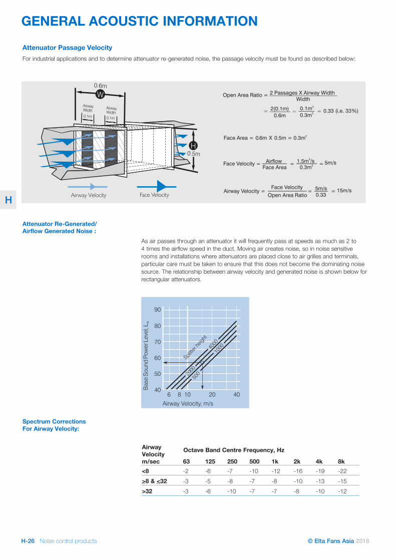
Attenuator Passage VelocityFor industrial applications and to determine attenuator re-generated noise, the passage velocity must be found as described below:
Attenuator Re-Generated/ Airflow Generated Noise :
As air passes through an attenuator it will frequently pass at speeds as much as 2 to 4 times the airflow speed in the duct. Moving air creates noise, so in noise sensitive rooms and installations where attenuators are placed close to air grilles and terminals, particular care must be taken to ensure that this does not become the dominating noise source. The relationship between airway velocity and generated noise is shown below for rectangular attenuators.
Spectrum Corrections For Airway Velocity:
Figure 1.
Figure 2.
07 10 12 15 17 20 22 2520
30
40
50
60
Attenuator Model No.
%Fr
eeA
rea
Figure 4.
4 6 10 2020
4
2
8
12
No. of Modules
dBIn
crea
se
6 8 10 20 4040
50
60
70
80
90
Airway Velocity, m/s
Bas
eSo
und
Pow
erLe
vel,
L W
500
1000
2000
4000
Splitte
r heig
ht
14
10
6
1 module
200 mm
100 mm
Airway width (in mm)
Airflow
Tapered Splitter: shown with 3 modulesIf airway width were 150mm and length 1500mm,
the silencer would be an RT15D.
Airway Velocity m/sec 63 125 250 500 1k 2k 4k 8k<8 -2 -6 -7 -10 -12 -16 -19 -22>8 & <32 -3 -5 -8 -7 -8 -10 -13 -15>32 -3 -6 -10 -7 -7 -8 -10 -12
Octave Band Centre Frequency, Hz
Noise control products H-27© Elta Fans Asia 2018
H
GENERAL ACOUSTIC INFORMATION
Width (mm)
Height (mm) 63 125 250 500 1k 2k 4k 8k
100 100 6.7 6.8 7.1 11.6 33.1 34.0 15.4 9.0100 150 5.0 5.4 6.2 10.6 29.2 29.4 14.2 8.6100 200 4.2 4.7 5.7 10.1 27.1 27.0 13.5 8.4100 250 3.8 4.4 5.4 9.7 25.9 25.5 13.1 8.3150 150 3.6 4.1 5.2 9.5 25.0 24.6 12.8 8.2150 250 2.7 3.2 4.4 8.5 21.4 20.6 11.6 7.8150 300 2.5 3.0 4.2 8.3 20.5 19.5 11.3 7.7150 400 2.3 2.7 3.9 7.9 19.3 18.2 10.9 7.6200 200 2.5 3.0 4.2 8.3 20.5 19.5 11.3 7.7200 300 2.1 2.4 3.7 7.6 18.1 16.9 10.4 7.4200 400 2.0 2.2 3.4 7.2 16.8 15.5 9.9 7.3200 600 1.8 2.0 3.1 6.8 15.5 14.1 9.4 7.1250 250 2.1 2.4 3.6 7.4 17.6 16.3 10.2 7.4250 400 1.8 1.9 3.1 6.7 15.2 13.8 9.3 7.0250 500 1.7 1.8 2.9 6.5 14.4 13.0 9.0 6.9250 600 1.7 1.7 2.8 6.3 13.9 12.4 8.7 6.8300 300 1.8 2.0 3.1 6.8 15.5 14.1 9.4 7.1300 400 1.7 1.8 2.9 6.4 14.1 12.7 8.9 6.9300 600 1.6 1.6 2.6 5.9 12.7 11.2 8.3 6.6300 800 1.4 1.5 2.5 5.8 12.1 10.5 8.0 6.6400 400 1.6 1.6 2.6 5.9 12.7 11.2 8.3 6.6400 600 1.2 1.3 2.3 5.5 11.3 9.8 7.7 6.4400 800 1.1 1.2 2.1 5.2 10.5 9.0 7.3 6.3400 1000 1.0 1.1 2.0 5.0 10.0 8.5 7.1 6.2500 500 1.2 1.3 2.2 5.4 11.0 9.5 7.5 6.4500 600 1.1 1.2 2.1 5.2 10.3 8.8 7.2 6.2500 800 1.0 1.0 1.9 4.8 9.5 8.0 6.9 6.1500 1000 0.9 0.9 1.8 4.7 9.0 7.5 6.6 6.0600 600 1.0 1.1 1.9 4.9 9.7 8.2 6.9 6.1600 800 0.9 0.9 1.7 4.6 8.8 7.3 6.5 5.9600 1200 0.8 0.8 1.5 4.2 7.9 6.5 6.1 5.7600 1600 0.7 0.7 1.4 4.1 7.5 6.1 5.8 5.6800 800 0.8 0.8 1.5 4.2 7.9 6.5 6.1 5.7800 1000 0.7 0.7 1.4 4.0 7.4 6.0 5.8 5.6800 1200 0.6 0.6 1.3 3.9 7.0 5.6 5.6 5.5800 1600 0.6 0.6 1.2 3.7 6.5 5.2 5.3 5.41000 1000 0.6 0.6 1.3 3.8 6.8 5.4 5.5 5.51000 1200 0.6 0.6 1.2 3.6 6.4 5.1 5.3 5.31000 1600 0.5 0.5 1.1 3.4 5.9 4.6 5.0 5.21000 2000 0.5 0.5 1.0 3.3 5.5 4.3 4.8 5.11200 1200 0.5 0.5 1.1 3.4 6.0 4.7 5.1 5.21200 1600 0.5 0.5 1.0 3.2 5.4 4.2 4.8 5.11200 2000 0.4 0.4 0.9 3.1 5.1 3.9 4.6 5.01200 2400 0.4 0.4 0.9 3.0 4.9 3.7 4.4 4.9
Width (mm)
Height (mm) 63 125 250 500 1k 2k 4k 8k
100 100 11.8 12.6 14.8 24.4 33.1 34.0 15.4 9.0100 150 8.5 9.9 12.8 22.3 29.2 29.4 14.2 8.6100 200 7.1 8.6 11.7 21.2 27.1 27.0 13.5 8.4100 250 6.4 7.9 11.1 20.5 25.9 25.5 13.1 8.3150 150 5.9 7.4 10.7 20.0 25.0 24.6 12.8 8.2150 250 4.2 5.6 9.0 17.9 21.4 20.6 11.6 7.8150 300 3.9 5.1 8.5 17.3 20.5 19.5 11.3 7.7150 400 3.4 4.6 8.0 16.6 19.3 18.2 10.9 7.6200 200 3.9 5.1 8.5 17.3 20.5 19.5 11.3 7.7200 300 3.1 4.1 7.4 15.9 18.1 16.9 10.4 7.4200 400 2.7 3.7 6.8 15.1 16.8 15.5 9.9 7.3200 600 2.4 3.2 6.2 14.2 15.5 14.1 9.4 7.1250 250 2.9 3.9 7.2 15.5 17.6 16.3 10.2 7.4250 400 2.4 3.1 6.1 14.0 15.2 13.8 9.3 7.0250 500 2.2 2.9 5.7 13.5 14.4 13.0 9.0 6.9250 600 2.1 2.7 5.5 13.1 13.9 12.4 8.7 6.8300 300 2.4 3.2 6.2 14.2 15.5 14.1 9.4 7.1300 400 2.2 2.8 5.6 13.3 14.1 12.7 8.9 6.9300 600 2.0 2.4 5.0 12.3 12.7 11.2 8.3 6.6300 800 1.6 2.2 4.8 11.9 12.1 10.5 8.0 6.6400 400 2.0 2.4 5.0 12.3 12.7 11.2 8.3 6.6400 600 1.5 2.0 4.4 11.4 11.3 9.8 7.7 6.4400 800 1.3 1.7 4.0 10.8 10.5 9.0 7.3 6.3400 1000 1.2 1.6 3.8 10.4 10.0 8.5 7.1 6.2500 500 1.4 1.9 4.3 11.1 11.0 9.5 7.5 6.4500 600 1.3 1.7 4.0 10.7 10.3 8.8 7.2 6.2500 800 1.1 1.5 3.6 10.0 9.5 8.0 6.9 6.1500 1000 1.0 1.3 3.4 9.6 9.0 7.5 6.6 6.0600 600 1.1 1.5 3.7 10.2 9.7 8.2 6.9 6.1600 800 1.0 1.3 3.3 9.5 8.8 7.3 6.5 5.9600 1200 0.8 1.1 2.9 8.8 7.9 6.5 6.1 5.7600 1600 0.8 1.0 2.7 8.4 7.5 6.1 5.8 5.6800 800 0.8 1.1 2.9 8.8 7.9 6.5 6.1 5.7800 1000 0.8 1.0 2.7 8.3 7.4 6.0 5.8 5.6800 1200 0.7 0.9 2.5 8.0 7.0 5.6 5.6 5.5800 1600 0.6 0.8 2.3 7.6 6.5 5.2 5.3 5.41000 1000 0.7 0.8 2.4 7.8 6.8 5.4 5.5 5.51000 1200 0.6 0.8 2.3 7.5 6.4 5.1 5.3 5.31000 1600 0.6 0.7 2.0 7.1 5.9 4.6 5.0 5.21000 2000 0.5 0.6 1.9 6.8 5.5 4.3 4.8 5.11200 1200 0.6 0.7 2.1 7.2 6.0 4.7 5.1 5.21200 1600 0.5 0.6 1.9 6.7 5.4 4.2 4.8 5.11200 2000 0.5 0.5 1.7 6.4 5.1 3.9 4.6 5.01200 2400 0.4 0.5 1.7 6.2 4.9 3.7 4.4 4.9
d (mm) 63 125 250 500 1k 2k 4k 8k100 0 0 0 1 6 11 10 10150 0 0 0 1 6 11 10 10200 0 0 1 6 11 10 10 10250 0 0 1 6 11 10 10 10300 0 0 1 6 11 10 10 10400 0 1 6 11 10 10 10 10500 0 1 6 11 10 10 10 10600 0 1 6 11 10 10 10 10800 1 6 11 10 10 10 10 101000 1 6 11 10 10 10 10 101200 1 6 11 10 10 10 10 101600 6 11 10 10 10 10 10 102000 6 11 10 10 10 10 10 102400 6 11 10 10 10 10 10 10
d (mm) 63 125 250 500 1k 2k 4k 8k100 0 0 0 1 4 7 7 7150 0 0 0 1 4 7 7 7200 0 0 1 4 7 7 7 7250 0 0 1 4 7 7 7 7300 0 0 1 4 7 7 7 7400 0 1 4 7 7 7 7 7500 0 1 4 7 7 7 7 7600 0 1 4 7 7 7 7 7800 1 4 7 7 7 7 7 71000 1 4 7 7 7 7 7 71200 1 4 7 7 7 7 7 71600 4 7 7 7 7 7 7 72000 4 7 7 7 7 7 7 72400 4 7 7 7 7 7 7 7
Table 1: 25mm lined duct
Table 3: Square lined bend with turning vanes
Insertion Loss, dB/metre Octave Band Centre Frequency (Hz)
Table 4: Square lined bend without turning vanes
Insertion Loss, dB/metre Octave Band Centre Frequency (Hz)
Insertion Loss, dB/bend Octave Band Centre Frequency (Hz)
Insertion Loss, dB/bend Octave Band Centre Frequency (Hz)
Table 2: 50mm lined ductReference Information: Acoustic Losses Of Lined Duct & Bends

© Elta Fans Asia 2018
For information about your nearest office, visit us online:Web www.eltafans.asiaEmail [email protected]
Elta Fans Asia
At Elta Fans we are dedicated to the continuous research and development of all our products. To provide you with the very best in air movement and ventilation, products supplied may differ from those illustrated and described in this publication. Confirmation of dimensions and data can be supplied on request from our team.
Related Documents