www.hiquel.com SLS SLS SLS SLS-500 500 500 500 Master Controller Master Controller Master Controller Master Controller Graphical programing with SLS-500-Configurator SLS-500 Master Controller Software manual

Welcome message from author
This document is posted to help you gain knowledge. Please leave a comment to let me know what you think about it! Share it to your friends and learn new things together.
Transcript

www.hiquel.com
SLSSLSSLSSLS----500500500500
Master ControllerMaster ControllerMaster ControllerMaster Controller Graphical programing with
SLS-500-Configurator
SLS-500 Master Controller Software manual
HIQUELHIQUELHIQUELHIQUEL SLS-500-Configurator
www.hiquel.com 2
Herbert Weiß, Helmut Maurer:
SLS-500 Master Controller – User Manual
Version: 4.03
Great care has been taken in the creation of the text, illustrations and program examples in this manual. Neither HIQUEL, there authors nor their interpreters may be held responsible for any errors herein, nor can they be held responsible or liable for consequences arising from any errors herein.
This manual is subject to copyright law. All rights are reserved.
This manual may not be copied in part or whole in any form including electronic media without the written consent of Hiquel. Neither may it be transferred in any other language suitable for machines or data processing facilities. Also rights for reproduction through lecture, radio or television transmission are reserved.
Hiquel copyrights this documentation and the accompanying software.
Copyright 2002-2004 by HIQUEL GmbH

HIQUELHIQUELHIQUELHIQUEL SLS-500-Configurator
www.hiquel.com 3
Attention! You are handling dangerous electrical current!
� Disconnect the supply voltage before making any wiring modifications.
� Ensure that the system cannot be switched on accidentally.
� Ensure that the device and its surroundings are potential free.
� Please refer to the specific installation and mounting instructions.
� Qualified personal only should handle the device.
� The device has to be mounted in such a way that no unintentional operation may occur.
� All control and supply voltage wiring must be routed so that no inductive or capacitive interference or any other severe electrical noise disturbance may interfere with the device.
� Supply voltage variation must not exceed the specifications in the technical details. If so, proper performance of the device cannot be guaranteed.
� Emergency installations according to EN60204/IEC204 (VDE0113) must remain active in all modes of the automated installation. Activation of the emergency installation must not cause an uncontrolled or undefined start cycle.
� The software engineer has to make sure, that no failure functions of the automated installation may occur when line faults or core faults arise.
� Notwithstanding the above, local regulations must be observed in all installations.
HIQUELHIQUELHIQUELHIQUEL SLS-500-Configurator
www.hiquel.com 4
Content
ATTENTION! YOU ARE HANDLING DANGEROUS ELECTRICAL CURRENT!.................................................................................................3 CONTENT..................................................................................................4 SLS-500 MASTER CONTROLLER .........................................................14 PREFACE ................................................................................................15 SYSTEM REQUIREMENTS.....................................................................16 CREATE NEW PROJECT .......................................................................17
Start PowerPoint..........................................................................17 Open SLS-500-Configurator sample ...........................................17 Save new project .........................................................................18 Start presentation (press F5).......................................................19 SLS-500-Configurator does not respond.....................................20 SLS-500-Configurator responds successfully .............................20 IMPORTANT ADVICE.................................................................21
CONFIGURATION ...................................................................................22 Configuration page ......................................................................22 Add objects..................................................................................23 Delete objects..............................................................................24 Program object priority ................................................................25 Define in/outputs..........................................................................25
PROJECT.................................................................................................26 Project:Info ..................................................................................26 Project:Import ..............................................................................27 Project: Update I/Os ....................................................................28
PAGES .....................................................................................................29 Page: Zoom all ............................................................................29
HIQUELHIQUELHIQUELHIQUEL SLS-500-Configurator
www.hiquel.com 5
Page: Zoom 100%.......................................................................29 Page: Zoom 75%.........................................................................29 Page: Zoom 60%.........................................................................29 Page: New...................................................................................29 Page: Del.....................................................................................30 Page: Copy..................................................................................31 Page: Ignore ................................................................................31 Page: Go to .................................................................................32 Page: Execute .............................................................................33
PAGE EXECUTION .................................................................................34 Standard page .............................................................................34 Page/Execute/every 1ms.............................................................36 Page/Execute/every 10ms...........................................................36 Page/Execute/every 100ms.........................................................36 Page/Execute/clock every second...............................................37 Page/Execute/clock every minute ...............................................37 Page/Execute/clock every hour ...................................................37 Page/Execute/clock every day ....................................................38 Page/Execute/clock every Week.................................................38 Page/Execute/clock every Month ................................................38 Page/Execute/clock every Year...................................................39 Page/Execute/only for initialisation..............................................39 Page/Execute/on binary memory ................................................39 Page/Execute/on analogue memory ...........................................40
CONNECTIONS.......................................................................................41 Creation .......................................................................................41 Mind the direction of the arrow ....................................................41 Create connections......................................................................42 Change the style of the line .........................................................43
DATA TYPES OF SLS-500-CONFIGURATOR .......................................44
HIQUELHIQUELHIQUELHIQUEL SLS-500-Configurator
www.hiquel.com 6
Bit data ........................................................................................44 Analogue data .............................................................................44 Text data......................................................................................44
CONSTANTS OF SLS-500-CONFIGURATOR .......................................45 Binary constants ..........................................................................45 Analogue constants .....................................................................47 Text constants .............................................................................49
SPECIAL FLAGS .....................................................................................51 Special flag: START ....................................................................51 Special flag: every 1ms ...............................................................51 Special flag: every 10ms .............................................................52 Special flag: every 100ms ...........................................................52 Special flag: Clock every second.................................................52 Special flag: Clock every minute .................................................53 Special flag: Clock every hour .....................................................53 Special flag: Clock every day.......................................................53 Special flag: Clock every week....................................................53 Special flag: Clock every month ..................................................54 Special flag: Clock every year .....................................................54
MEMORIES..............................................................................................55 Bit memory ..................................................................................56 SET bit memory...........................................................................56 RESET bit memory......................................................................56 TOGGLE bit memory...................................................................57 Analogue memory .......................................................................58 IF rising edge SET analogue memory.........................................59 IF falling edge SET analogue memory ........................................60 IF both edges SET analogue memory.........................................60 IF permanent high SET analogue memory .................................60 IF permanent low SET analogue memory...................................61
HIQUELHIQUELHIQUELHIQUEL SLS-500-Configurator
www.hiquel.com 7
Text memory ...............................................................................61 IF rising edge SET text memory..................................................62 IF falling edge SET text memory.................................................62 IF both edges SET text memory..................................................63 IF permanent high SET text memory ..........................................63 IF permanent low SET text memory............................................63
BINARY OPERATORS ............................................................................65 Binary operator: Binary AND .......................................................65 Binary operator: Binary OR..........................................................66 Binary operator: Binary EXCLUSIVE OR ....................................67 Binary operator: Binary NEGATION ............................................68 Binary operator: Rising edge .......................................................68 Binary operator: falling edge........................................................69 Binary operator: Both edges........................................................69 Binary operator: Split ...................................................................70
ANALOGUE OPERATORS......................................................................71 Analogue operator: Addition ........................................................71 Analogue operator: Subtraction...................................................72 Analogue operator: Multiplication ................................................73 Analogue operator: Division ........................................................73 Analogue operator: Modulo (read part of a value)................74 Analogue operator: Shift left ........................................................75 Analogue operator: Shift right......................................................75 Analogue operator: Greater than.................................................76 Analogue operator: Greater or equal...........................................77 Analogue operator: Equal............................................................77 Analogue operator: Not equal......................................................78 Analogue operator: Less or equal ...............................................79 Analogue operator: Less .............................................................79

HIQUELHIQUELHIQUELHIQUEL SLS-500-Configurator
www.hiquel.com 8
Analogue operator: Logical AND.................................................80 Analogue operator: Logical OR ...................................................81 Analogue operator: Logical NOT.................................................81 Analogue operator: Split ..............................................................82
TEXT OPERATORS ................................................................................83 Text operator: Combine text........................................................83 Text operator: Greater.................................................................84 Text operator: Greater or equal...................................................84 Text operator: Equal ....................................................................85 Text operator: Not equal..............................................................85 Text operator: Less or equal .......................................................86 Text operator: Less .....................................................................87 Text operator: Split ......................................................................87 Text operator: Sub String ............................................................88 Text operator: Left String.............................................................89 Text operator: Right String ..........................................................90 Text operator: String Length........................................................91
COUNTER................................................................................................92 Counter: Count Up.......................................................................92 Counter: Count Down..................................................................93 Counter: Count Set......................................................................94 Counter: Count up with limit ........................................................95 Counter: Count down with limit....................................................96
CONVERSION .........................................................................................98 Conversion: Binary->Analogue....................................................98 Conversion: Analogue->Binary....................................................99 Conversion: Analogue Scale .....................................................101 Conversion: Text->Analogue.....................................................102 Conversion: Analogue->Text.....................................................104 Format characters .....................................................................105

HIQUELHIQUELHIQUELHIQUEL SLS-500-Configurator
www.hiquel.com 9
STATES .................................................................................................106 State: Select alternative function state ......................................106 Analogue state frame ................................................................107 Binary state................................................................................108 Example: STATE - Select alternative function ..........................109
COMMENTS ..........................................................................................110 Insert comment..........................................................................110
SYMBOLIC GROUPS ............................................................................111 Create symbolic groups.............................................................111
SYSTEM MEMORY ...............................................................................112 System: Binary memory ............................................................113 System: IF input is One SET binary memory ............................113 System: IF input is One DELETE binary memory .....................113 System: IF input is One INVERT binary memory ......................114 System: Analog memory ...........................................................115 System: Text memory ...............................................................115 System: System variable table ..................................................116
INCREMENTAL ENCODER...................................................................117 The Incremental Encoder ..........................................................117 Programming an incremental encoder ......................................118
I/O...........................................................................................................120 I/O: Digital Inputs .......................................................................120 I/O: Digital Outputs ....................................................................121 I/O: Analogue Inputs..................................................................123 I/O: Analogue Outputs ...............................................................124 I/O: Potentiometer .....................................................................126
GROUPS................................................................................................128 Export groups ............................................................................128 Import groups ............................................................................129 Delete groups ............................................................................129

HIQUELHIQUELHIQUELHIQUEL SLS-500-Configurator
www.hiquel.com 10
Adjust controller.........................................................................130 The PID – Controller..................................................................131 Transmission-function of a PID – controller ..............................131
OBJECTS...............................................................................................133 Objects: Timer ...........................................................................133 Objects: Timer: ON delay ..........................................................135 Objects: Timer: OFF delay ........................................................135 Objects: Timer: ON OFF delay..................................................135 Objects: Timer: ON pulse..........................................................136 Objects: Timer: OFF pulse ........................................................136 Objects: Timer: ON OFF pulse..................................................136 Objects: Timer: Recycler high first ............................................137 Objects: Timer: Recycler low first..............................................137 Objects: Timer: Delay................................................................137
REAL TIME CLOCK...............................................................................138 Objects: clock: Exact time .........................................................138 Objects: clock: Time period.......................................................139 Objects: clock: Exact date .........................................................139 Objects: clock: Date period .......................................................139 Objects: clock: Exact date&time................................................140 Objects: clock: Date&time period ..............................................140 Objects: clock: Exact Weekday.................................................141 Objects: clock: Weekday period................................................141 Objects: clock: Exact Week ......................................................141 Objects: clock: Week Period .....................................................142 Objects: clock: Analogue: Time.................................................142 Objects: clock: Analogue: Date .................................................143 Objects: clock: Analogue: Day of Week ....................................143 Objects: clock: Analogue: Week of year ...................................143 Objects: clock: Text: Time.........................................................144

HIQUELHIQUELHIQUELHIQUEL SLS-500-Configurator
www.hiquel.com 11
Objects: clock: Text: Date .........................................................144 Objects: clock: Text: Date&Time...............................................144 Objects: clock: Text: Day of Week ............................................145 Objects: clock: Text: Week of year ...........................................145
CAN OBJECTS (CANBUS)....................................................................146 Objects: CAN Message In .........................................................146 Objects: CAN Value In...............................................................147 Objects: CAN Text In.................................................................147 Objects: Receive FULL CAN Message .....................................148 Objects: CAN Message Out ......................................................148 Objects: CAN Value Out............................................................149 Objects: CAN Text Out..............................................................149 Objects: Send FULL CAN message..........................................150
SIO FUNCTIONS (SERIAL INPUT/OUTPUT) .......................................151 Objects: SIO: Send Text............................................................151 Objects: SIO: Send Byte............................................................152 Objects: SIO: Send Word..........................................................152 Objects: SIO: Send DWord .......................................................152 Objects: SIO: Receive Byte .......................................................153 Objects: SIO: Receive Text .......................................................153
TERMINAL FUNCTIONS (MMI).............................................................154 Objects: Terminal: Show Message............................................154 Objects: Terminal: Show Value .................................................156 Objects: Terminal: Show Text ...................................................157 Objects: Terminal: Edit Text ......................................................158 Objects: Terminal: Edit Value....................................................160 Objects: Terminal: Menu ...........................................................162 Objects: Terminal: Select item ..................................................164 Objects: Terminal: Update Value ..............................................166 Objects: Terminal: Update Text ................................................167
HIQUELHIQUELHIQUELHIQUEL SLS-500-Configurator
www.hiquel.com 12
Objects: Terminal: Key pressed ................................................167 MEMORY CARD ....................................................................................169
Objects: MemoryCard: Read Value into SLS500 memory........169 Objects: MemoryCard: Read Text into SLS500 memory ..........170 Objects: MemoryCard: Write Value to card...............................170 Objects: MemoryCard: Write Text to card.................................171 Objects: MemoryCard: Read Value from card ..........................171 Objects: MemoryCard: Read Text from card ............................172 Objects: MemoryCard: Write Analogue Value...........................172 Objects: MemoryCard: Write Text Value...................................173
SMS........................................................................................................174 Objekte: SMS: Start new short message ..................................174 Objects: SMS: Add Text to short message ...............................175 Objects: SMS: Send short message via GSM...........................175 Objects: SMS: Call Phone.........................................................176 Objects: SMS: Short message received....................................176 Objects: SMS: Check short message Text ...............................177 Objects: SMS: Skip short message blanks ...............................177 Objects: SMS: Get short message Analogue Value..................178 Objekte: SMS: Get short message Text....................................179
DEBUG...................................................................................................180 Debug: Add Symbols.................................................................180 Debug: Add Monitor...................................................................181 Debug: Monitor Binary Memory.................................................181 Debug: Monitor Analogue Memory............................................182 Debug: Monitor Text Memory....................................................182 Debug: Set Breakpoint ..............................................................182 Debug: Delete Breakpoint .........................................................183 Debug: Display System Information ..........................................183
RUN........................................................................................................184
HIQUELHIQUELHIQUELHIQUEL SLS-500-Configurator
www.hiquel.com 13
Run: Compile.............................................................................184 Error during compilation ............................................................184 Compilation successful..............................................................185 Run: Simulate ............................................................................185 Run: Download & Run ...............................................................186 Run: Start ..................................................................................186 Run: Stop...................................................................................186 Run: Erase.................................................................................186 Run: Show.................................................................................186 Read/write binary memory.........................................................190 Read/write analogue memory....................................................190 Read/write text memory.............................................................190 SPS not found ...........................................................................191 Choose serial port .....................................................................191 Online Data exchange...............................................................194 Memory read/write.....................................................................194
SIMULATOR ..........................................................................................195 Start simulation..........................................................................195 Simulation: Binary Memory........................................................196 Simulation: Analogue Memory...................................................197 Simulation: Text Memory...........................................................198 Simulation: Logging ...................................................................199 Close Simulator .........................................................................200 Continue Simulator ....................................................................200 Exit Simulator ............................................................................200
CONTACT..............................................................................................201

HIQUELHIQUELHIQUELHIQUEL SLS-500-Configurator
www.hiquel.com 14
SLS-500 Master Controller
Safety precautions
Danger to life through electrical current!
Only skilled personal trained in electro-engineering should perform the described steps in the following chapters. Please observe the country specific rules and standards. Do not perform any electrical work while the device is connected to power.
Pay attention to following rules
� Switch off the automated installation.
� Disable any automatic restart system
� Electrically isolate the installation
� Cover any non-isolated areas

HIQUELHIQUELHIQUELHIQUEL SLS-500-Configurator
www.hiquel.com 15
Preface
„Der Grund, warum die Menschen ihre Dienste zum Geschenk machen, ist der Wunsch, etwas zu tun, was – vielleicht im Gegensatz zu ihrer täglichen Arbeit - wirklich zählt!“
Charles Trueheart

HIQUELHIQUELHIQUELHIQUEL SLS-500-Configurator
www.hiquel.com 16
System Requirements
System specification for SLS-500-Configurator:
Your system must meet the following requirements to run SLS-500-Configurator:
� A free serial RS232 port (COM1 - COM8)
� A previously installed version of Microsoft PowerPoint® in version Office 2000 or Office XP
� Processor: 90 - 166 Pentium
� RAM: min. 16 MB (32 MB for Win NT) opt. 64 MB (128 MB for Win NT)
� Free memory: min. 20 MB opt. 40 MB

HIQUELHIQUELHIQUELHIQUEL SLS-500-Configurator
www.hiquel.com 17
Create new project SLS-500-Configurator requires Microsoft PowerPoint.
Start PowerPoint
To work with SLS-500-Configurator you have to start PowerPoint first. Then open the file SLS-500-Configurator.ppt.
Open SLS-500-Configurator sample
Proceed as follows: After starting PowerPoint choose File/Open from the menu. Then choose the folder SLS-500-Configurator from the file dialogue. You will find the file SLS-500-Configurator.ppt.
Open the file. The following screen will be displayed.

HIQUELHIQUELHIQUELHIQUEL SLS-500-Configurator
www.hiquel.com 18
Save new project
Save the presentation under the project name of your choice in a file of your choice. To do these choose from the menu the entry file/save. The window shown below appears. Enter „My first project“ for example and confirm the input by clicking the save command button.

HIQUELHIQUELHIQUELHIQUEL SLS-500-Configurator
www.hiquel.com 19
Start presentation (press F5)
In order to install the components necessary for SLS-500-Configurator you must start the presentation. Choose ‘Slide Show’/’View show’ from the menu options. Now the start page opens. Click in the black-bordered frame:
SLS-500-Configurator now installs all necessary components and confirms it has started with the following message:
�
HIQUELHIQUELHIQUELHIQUEL SLS-500-Configurator
www.hiquel.com 20
SLS-500-Configurator does not respond
If you have no response from SLS-500-Configurator after a half-minute, it is probably that your PowerPoint settings do not allow macros to run.
You can change this setting in the menu option ‘Tools’/’Macro’/’Security’. If you chose the security level high, no macros are carried out. To activate the macros you have to choose a security level of medium or low. If you choose medium PowerPoint will question while loading whether macros may become carried out or not.
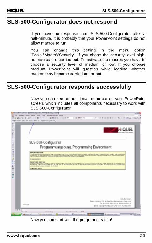
SLS-500-Configurator responds successfully
Now you can see an additional menu bar on your PowerPoint screen, which includes all components necessary to work with SLS-500-Configurator:
Now you can start with the program creation!
HIQUELHIQUELHIQUELHIQUEL SLS-500-Configurator
www.hiquel.com 21
IMPORTANT ADVICE
Do not delete any objects of this PowerPoint presentation except those you have created yourself. If you do you will endanger the function of the SLS-500-Configurator program!!!
HIQUELHIQUELHIQUELHIQUEL SLS-500-Configurator
www.hiquel.com 22
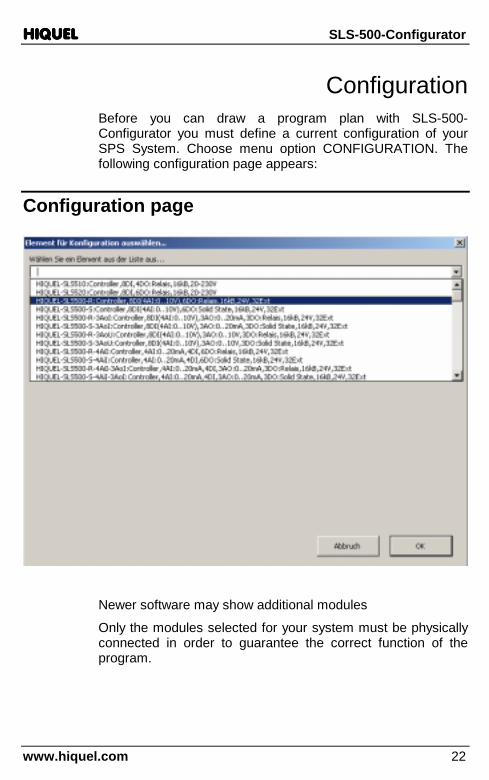
Configuration Before you can draw a program plan with SLS-500-Configurator you must define a current configuration of your SPS System. Choose menu option CONFIGURATION. The following configuration page appears:
Configuration page
Newer software may show additional modules
Only the modules selected for your system must be physically connected in order to guarantee the correct function of the program.
HIQUELHIQUELHIQUELHIQUEL SLS-500-Configurator
www.hiquel.com 23
Add objects
In order to add a new expansion module to the current configuration select the desired module from the configuration page and click OK:
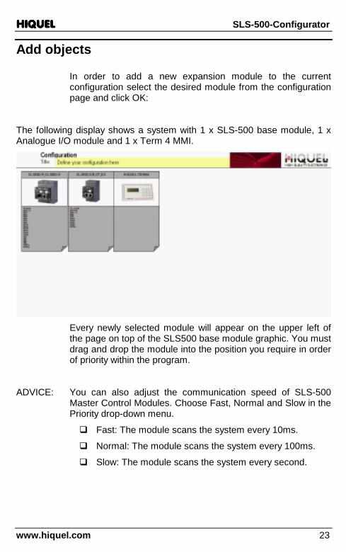
The following display shows a system with 1 x SLS-500 base module, 1 x Analogue I/O module and 1 x Term 4 MMI.
Every newly selected module will appear on the upper left of the page on top of the SLS500 base module graphic. You must drag and drop the module into the position you require in order of priority within the program.
ADVICE: You can also adjust the communication speed of SLS-500 Master Control Modules. Choose Fast, Normal and Slow in the Priority drop-down menu.
� Fast: The module scans the system every 10ms.
� Normal: The module scans the system every 100ms.
� Slow: The module scans the system every second.

HIQUELHIQUELHIQUELHIQUEL SLS-500-Configurator
www.hiquel.com 24
When new module added:
after new position selected!
Delete objects
Select the desired module and delete it by pressing Del.
ADVICE: The module will only be deleted in the configuration page. Any programmed object of the deleted module will not be deleted from your program! This will be detected when you attempt to compile your program. These objects must be deleted manually
HIQUELHIQUELHIQUELHIQUEL SLS-500-Configurator
www.hiquel.com 25
Program object priority
SLS-500-Configurator interprets the priority of the program objects from left to right and from top to bottom of the program page. The remote numbers are allocated exactly the same way. The base module has the definition L1. All expansion modules have the definition Remote. Beginning with a continuous number from 1. R1 is the first expansion; R2 is the second and so on.
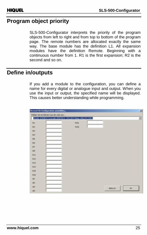
Define in/outputs
If you add a module to the configuration, you can define a name for every digital or analogue input and output. When you use the input or output, the specified name will be displayed. This causes better understanding while programming.
HIQUELHIQUELHIQUELHIQUEL SLS-500-Configurator
www.hiquel.com 26
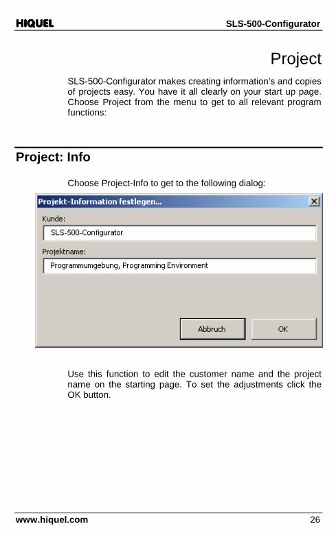
Project SLS-500-Configurator makes creating information’s and copies of projects easy. You have it all clearly on your start up page. Choose Project from the menu to get to all relevant program functions:
Project: Info
Choose Project-Info to get to the following dialog:
Use this function to edit the customer name and the project name on the starting page. To set the adjustments click the OK button.

HIQUELHIQUELHIQUELHIQUEL SLS-500-Configurator
www.hiquel.com 27
Project: Import
Choose this function to import a page from another project into your current project.
The following dialog will appear:
Click the x button to abort the process, otherwise click on Open Project.

HIQUELHIQUELHIQUELHIQUEL SLS-500-Configurator
www.hiquel.com 28
The page number and the page name will be displayed.
Now choose the desired page of the project from the list.
After clicking the OK button the selected page will be put into your current project!
Project: Update I/Os
You can edit the already set descriptions of the inputs and outputs with one entry. The change of the descriptions has to be accomplished on the configuration page.
After updating the I/O names the description of the in- and outputs from the configuration page will correspond with the whole project again.
Choose Update I/Os from the menu to start the update.

HIQUELHIQUELHIQUELHIQUEL SLS-500-Configurator
www.hiquel.com 29
Pages SLS-500-Configurator enables you to draw as many complex graphs as desired over as many pages as you want. Choose the menu option Page to get to the following options:
Page: Zoom all
The active page will be displayed completely screen filling.
Page: Zoom 100%
The page will be displayed with a zoom factor of 100%
Page: Zoom 75%
The page will be displayed with a zoom factor of 75%.
Page: Zoom 60%
The page will be displayed with a zoom factor of 60%.
Page: New
SLS-500-Configurator places a new programming page before the active page. Therefore if you want to insert a new page after the active page you must advance one page before inserting the new page

HIQUELHIQUELHIQUELHIQUEL SLS-500-Configurator
www.hiquel.com 30
Now define the title of the new programming page:
For this you have to click into the text field and type in the text:
INFO: You can spread your program over as many SLS-500-
Configurator pages as desired!
IMPORTANT: SLS-500-Configurator programs can only be drawn on programming pages. All other PowerPoint pages will be left out during compilation.
Page: Del
With this command you can delete the active SLS-500-Configurator programming page. After choosing this menu option the following message occurs:
HIQUELHIQUELHIQUELHIQUEL SLS-500-Configurator
www.hiquel.com 31
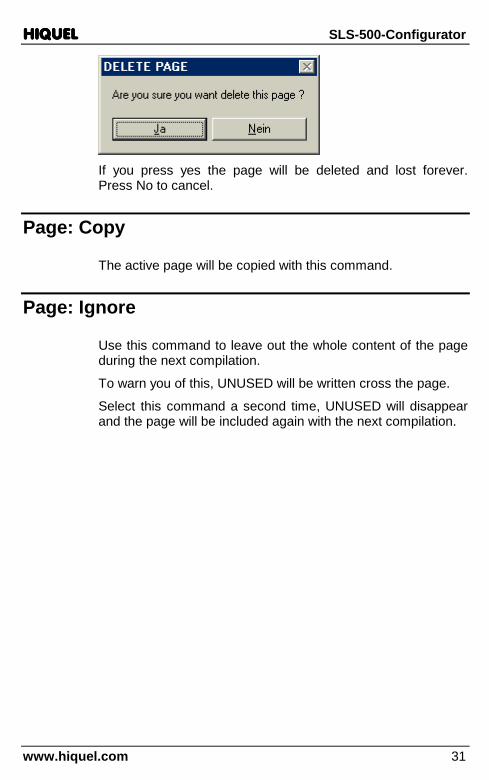
If you press yes the page will be deleted and lost forever. Press No to cancel.
Page: Copy
The active page will be copied with this command.
Page: Ignore
Use this command to leave out the whole content of the page during the next compilation.
To warn you of this, UNUSED will be written cross the page.
Select this command a second time, UNUSED will disappear and the page will be included again with the next compilation.

HIQUELHIQUELHIQUELHIQUEL SLS-500-Configurator
www.hiquel.com 32
Page: Go to
With this command you can quickly jump to another page of the project. SLS-500-Configurator shows you a detailed overview of all pages with page numbers and titles. Just click onto the desired page and press OK. The page will display immediately!
HIQUELHIQUELHIQUELHIQUEL SLS-500-Configurator
www.hiquel.com 33
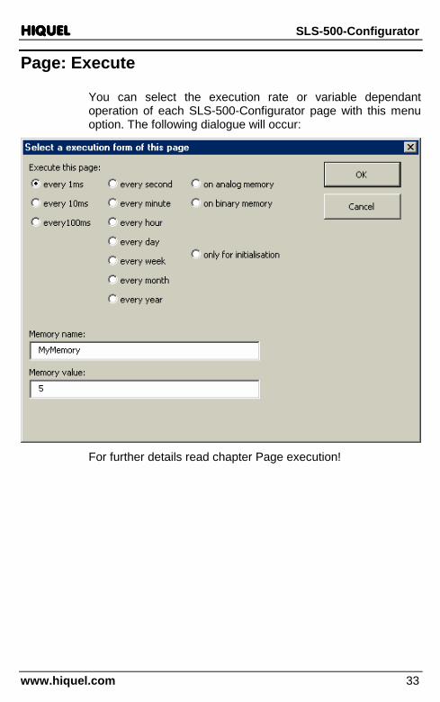
Page: Execute
You can select the execution rate or variable dependant operation of each SLS-500-Configurator page with this menu option. The following dialogue will occur:
For further details read chapter Page execution!

HIQUELHIQUELHIQUELHIQUEL SLS-500-Configurator
www.hiquel.com 34
Page execution This chapter deals with the various types of SLS-500-Configurator page execution.
Standard page
A regular SLS-500-Configurator page is created with the command Page/New. If you create a procedure on this page, as shown below, the page will be executed permanently.
This means that SLS500 executes the page as often as it is possible bearing in mind program length and other program priorities.
You can also select the execution of the page by adding an execution format.
Choose Page/Execute from the menu to get to the following dialogue:

HIQUELHIQUELHIQUELHIQUEL SLS-500-Configurator
www.hiquel.com 35
After choosing an execution format the setting will be displayed on the top right of the page.

HIQUELHIQUELHIQUELHIQUEL SLS-500-Configurator
www.hiquel.com 36
To delete the execution format, you just have to click the symbol on the top right and press the key Del.
Choose from the following execution formats:
Page/Execute/every 1ms
Symbol:
cyclicevery
1ms
cyclicevery
1ms
Function: The page will be executed every 1ms. This function is not available with all SLS500 types!
Page/Execute/every 10ms
Symbol:
cyclicevery10ms
cyclicevery10ms
Function: The page will be executed every 10ms.
Page/Execute/every 100ms
Symbol:
cyclicevery
100ms
cyclicevery
100ms
Function: The page will be executed every 100ms.

HIQUELHIQUELHIQUELHIQUEL SLS-500-Configurator
www.hiquel.com 37
Page/Execute/clock every second
Symbol:
CLOCKevery
second�������� CLOCK
everysecond
��������
Function: The page will be executed exactly every second. The function is only available with SLS500, which have a real time clock.
Page/Execute/clock every minute
Symbol:
CLOCKevery
minute�������� CLOCK
everyminute
��������
Function: The page will be executed exactly every minute. The function is only available with SLS500, which have a real time clock.
Page/Execute/clock every hour
Symbol:
CLOCKeveryhour
�������� CLOCKeveryhour
��������
Function: The page will be executed exactly every hour. The function is only available with SLS500which have a real time clock.

HIQUELHIQUELHIQUELHIQUEL SLS-500-Configurator
www.hiquel.com 38
Page/Execute/clock every day
Symbol:
CLOCKevery
day�������� CLOCK
everyday
��������
Function: The page will be executed every day at exactly 00:00:00. The function is only available with SLS500, which have a real time clock.
Page/Execute/clock every Week
Symbol:
CLOCKeveryweek
�������� CLOCKeveryweek
��������
Function: The page will be executed every Monday at exactly 00:00:00. The function is only available with SLS500, which have a real time clock.
Page/Execute/clock every Month
Symbol:
CLOCKevery
month�������� CLOCK
everymonth
��������
Function: The page will be executed exactly on the first of every month at 00:00:00. The function is only available with SLS500, which have a real time clock.

HIQUELHIQUELHIQUELHIQUEL SLS-500-Configurator
www.hiquel.com 39
Page/Execute/clock every Year
Symbol:
CLOCKeveryyear
�������� CLOCKeveryyear
��������
Function: The page will be executed exactly every year on the 1st January at 00:00:00. The function is only available with SLS500, which have a real time clock.
Page/Execute/only for initialisation
Symbol: initialisation
1.1.1.1.1.1.1.1.initialisation
1.1.1.1.1.1.1.1.
Function: The page will be executed with every program start up. Use this function for example to initialise the system.
Page/Execute/on binary memory
Symbol:
binary value=1
MyMemoryMyMemory
binary value=1
MyMemoryMyMemory
Function: This function defines that the page will only be executed if the binary value MyMemory is 1.
HIQUELHIQUELHIQUELHIQUEL SLS-500-Configurator
www.hiquel.com 40
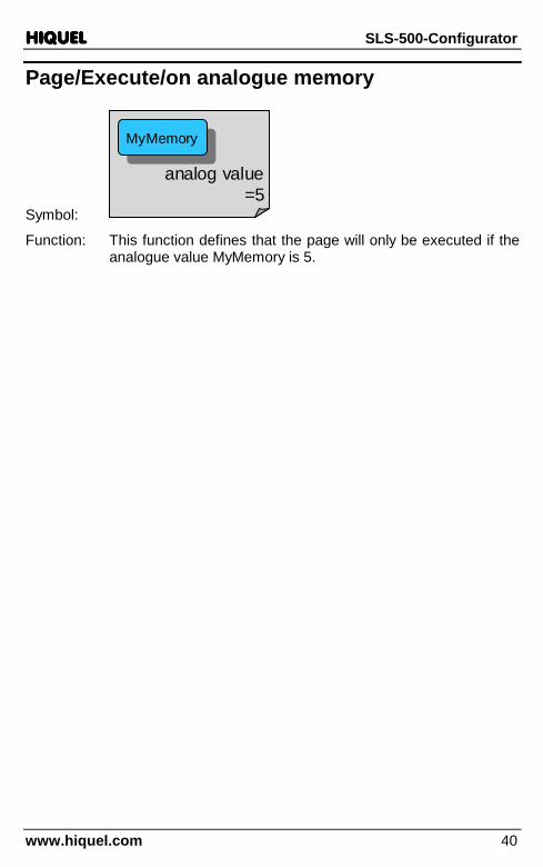
Page/Execute/on analogue memory
Symbol:
analog value=5
MyMemoryMyMemory
analog value=5
MyMemoryMyMemory
Function: This function defines that the page will only be executed if the analogue value MyMemory is 5.

HIQUELHIQUELHIQUELHIQUEL SLS-500-Configurator
www.hiquel.com 41
Connections Use the connections to connect the individual objects with each other. You can add a new connection object by choosing Line from the menu.
Creation
Symbol:
Data type: Depending on the object, connections can operate with all data types.
Function: The line connects the output of an object to the input of another object. It’s important for the connection that you have the correct direction of the arrow.
Mind the direction of the arrow
The arrowhead has always to be next to the input of the following object.
Example:
Wrong!
The connection was created the wrong way, since the arrowhead points at the output of the digital input. Take a look at the correct version:
Right!

HIQUELHIQUELHIQUELHIQUEL SLS-500-Configurator
www.hiquel.com 42
Create connections
When you click on the connection object, you will see coloured rectangles on both ends:
If the rectangles are green, the ends are free and are not linked with an object. Now move the cursor to one of the ends and left-click the arrow. Hold the mouse key and drag the line to an object.
You will notice that small blue symbols appear on the object that you drag the line to and that the line snaps to the nearest blue symbol. Select a suitable blue symbol and release the mouse key. The selected symbol turns from green too red. This is confirmation of a correct connection.
With the yellow symbol you can change the exact position of the connection:
Correct connections: Click on the connecting line. Both rectangles must be red:

HIQUELHIQUELHIQUELHIQUEL SLS-500-Configurator
www.hiquel.com 43
Wrong!
A connection may seem visually to be correct, but if one of the rectangles is be green the connection has not been made. Connect the line with the object again:
Right!
Change the style of the line
To change the line style, right-click the connection line and the following menu will appear:
Choose from, straight Connector (default), Elbow Connector or Curved Connector.

HIQUELHIQUELHIQUELHIQUEL SLS-500-Configurator
www.hiquel.com 44
Data types of SLS-500-Configurator
SLS-500-CONFIGURATOR supports three different data types:
Bit data
This data type can save exactly 1 Bit or the information 0 or 1.
Examples for bit data are digital inputs or outputs or status markers.
Analogue data
This data type has the ability to process signed analogue values to three decimal places. The maximum numerical range is –2147483.647 to +2147483.648.
Examples for analogue data are analogue inputs or analogue outputs.
Text data
This data type can save text messages. Depending on the destination system, character strings with different lengths are supported. Maximum 20 characters per text.
Examples for text data are messages for a display or serial communication objects.

HIQUELHIQUELHIQUELHIQUEL SLS-500-Configurator
www.hiquel.com 45
Constants of SLS-500-Configurator Constants define a fixed value. You can set constants for every data type of SLS-500-Configurator:
Using several constants with the same value, a „constant name“ can be predefined and jointly changed.
Binary constants
Binary constants define a value of 0 or 1. Choose from the SLS-500-Configurator – menu bar the command Flow/Constants. You will get to the following dialogue:
Now choose binary constant 0 and confirm your choice with OK.
The active programming page will insert the following symbol:
HIQUELHIQUELHIQUELHIQUEL SLS-500-Configurator
www.hiquel.com 46
const 0const 0
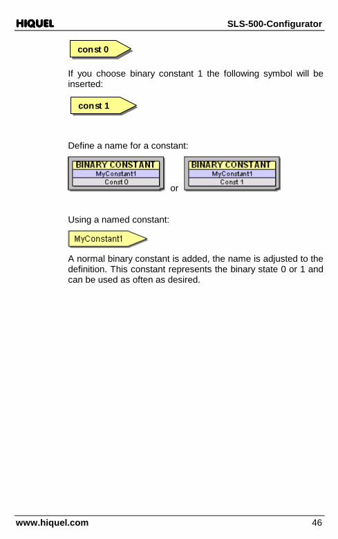
If you choose binary constant 1 the following symbol will be inserted:
const 1const 1
Define a name for a constant:
or
Using a named constant:
A normal binary constant is added, the name is adjusted to the definition. This constant represents the binary state 0 or 1 and can be used as often as desired.

HIQUELHIQUELHIQUELHIQUEL SLS-500-Configurator
www.hiquel.com 47
Analogue constants
Analogue constants define an analogue value. Choose Flow/Constants and the following dialogue will occur:
Choose Analogue constant and set a fixed value for the new constant in the field Analogue constant value. Then confirm with OK.
The following symbol will be inserted:
14.56714.567
For negative constants:
-345.56-345.56

HIQUELHIQUELHIQUELHIQUEL SLS-500-Configurator
www.hiquel.com 48
Also hexadecimal constants will be processed. Write hexadecimals as follows: starting character is 0x, a character string follows consisting of 0.9 or A.F or a..f. You can use a dot as a visual cut-off signal between the characters as often as you want. Example: 0xFF.A0. Hexadecimal constants will be processed as 32-Bit values:
0xff880xff88
In addition binary constants are supported. Binary constants start with a % character. A binary number 0 or 1 follows. You can use dots as visual cut-off signals.
Examples: %0 or %1
%1111.0101.0000
Define a name for a constant:
Using a named constant:
An analogue constant is added, the name is equal to the definition. This constant represents the analogue value 43,5 and can be used as often as desired.

HIQUELHIQUELHIQUELHIQUEL SLS-500-Configurator
www.hiquel.com 49
Text constants
Text constants define fixed character strings. Choose Flow/Constants and type the following into the text fields of the dialogue:
After clicking OK the following symbol will occur:

HIQUELHIQUELHIQUELHIQUEL SLS-500-Configurator
www.hiquel.com 50
INFO To change the value of a constant afterwards, click the text of the symbol and edit the text!
Define a name for a constant:
Using a named constant:
A normal text constant is added, the name is equal to the definition. This constant represents the text „MyText“ and can be used as often as desired.

HIQUELHIQUELHIQUELHIQUEL SLS-500-Configurator
www.hiquel.com 51
Special flags SLS-500-Configurator has a series of special flags, which display special signals. To insert a special flag choose Flow/Special flags. Select the desired flag and click OK.
Special flag: START
Symbol: STARTSTART
Data type: Bit
Function: This flag has the value 1only during the first program cycle. Otherwise this bit is always 0. Use this flag for example to initialise values.
Special flag: every 1ms
Symbol: ���� 1ms���� 1ms
Data type: Bit
HIQUELHIQUELHIQUELHIQUEL SLS-500-Configurator
www.hiquel.com 52
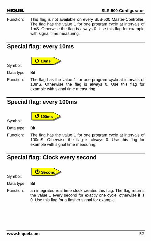
Function: This flag is not available on every SLS-500 Master-Controller. The flag has the value 1 for one program cycle at intervals of 1mS. Otherwise the flag is always 0. Use this flag for example with signal time measuring.
Special flag: every 10ms
Symbol: ���� 10ms���� 10ms
Data type: Bit
Function: The flag has the value 1 for one program cycle at intervals of 10mS. Otherwise the flag is always 0. Use this flag for example with signal time measuring
Special flag: every 100ms
Symbol: ���� 100ms���� 100ms
Data type: Bit
Function: The flag has the value 1 for one program cycle at intervals of 100mS. Otherwise the flag is always 0. Use this flag for example with signal time measuring.
Special flag: Clock every second
Symbol: ���� Second���� Second
Data type: Bit
Function: an integrated real time clock creates this flag. The flag returns the value 1 every second for exactly one cycle, otherwise it is 0. Use this flag for a flasher signal for example
HIQUELHIQUELHIQUELHIQUEL SLS-500-Configurator
www.hiquel.com 53
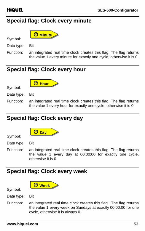
Special flag: Clock every minute
Symbol: ���� Minute���� Minute
Data type: Bit
Function: an integrated real time clock creates this flag. The flag returns the value 1 every minute for exactly one cycle, otherwise it is 0.
Special flag: Clock every hour
Symbol: ���� Hour���� Hour
Data type: Bit
Function: an integrated real time clock creates this flag. The flag returns the value 1 every hour for exactly one cycle, otherwise it is 0.
Special flag: Clock every day
Symbol: ���� Day���� Day
Data type: Bit
Function: an integrated real time clock creates this flag. The flag returns the value 1 every day at 00:00:00 for exactly one cycle, otherwise it is 0.
Special flag: Clock every week
Symbol: ���� Week���� Week
Data type: Bit
Function: an integrated real time clock creates this flag. The flag returns the value 1 every week on Sundays at exactly 00:00:00 for one cycle, otherwise it is always 0.

HIQUELHIQUELHIQUELHIQUEL SLS-500-Configurator
www.hiquel.com 54
Special flag: Clock every month
Symbol: ���� Month���� Month
Data type: Bit
Function: an integrated real time clock creates this flag. The flag returns the value 1 on the first of every month at exactly 00:00:00 for one cycle, otherwise it is always 0.
Special flag: Clock every year
Symbol: ���� Year���� Year
Data type: Bit
Function: an integrated real time clock creates this flag. The flag returns the value 1 every year exactly on the 1st of January at 00:00:00 for one cycle, otherwise it is always 0.

HIQUELHIQUELHIQUELHIQUEL SLS-500-Configurator
www.hiquel.com 55
Memories Use the memory spaces to store values of one of the three data types. These values can be reloaded any time at another place within the program to continue processing.
Every memory has a name.
INFO You can define the same name for a binary memory and an analogue memory the graphic colour tells you the difference. However take care which memory you are actually accessing!
Choose Flow/Memories from the menu, you can select the following memories:

HIQUELHIQUELHIQUELHIQUEL SLS-500-Configurator
www.hiquel.com 56
Bit memory
Symbol: MyMemoryMyMemory
Data type: Bit
Function: Bit memory saves one Bit and transmits it.
Examples: MyMemoryMyMemoryconst 1const 1
The constant value 1 will be transmitted to MyMemory.
1stMemory1stMemory 2ndMemory2ndMemoryL1.DI1L1.DI1
The current value of digital input L1.DI1 will be saved to the 1stMemory and also to the 2ndMemory.
MyMemoryMyMemory
L1.DO1L1.DO1
The active value of MyMemory will be transmitted to digital output L1.DO1.
SET bit memory
Symbol: SET
MyMemorySET
MyMemory
Data type: Bit
Function: If the input of the bit memory receives the value 1, MyMemory will be set to 1.
RESET bit memory
Symbol: RESET
MyMemoryRESET
MyMemory

HIQUELHIQUELHIQUELHIQUEL SLS-500-Configurator
www.hiquel.com 57
Data type: Bit
Function: If the input of the bit memory gets the value 1, MyMemory will be reset to 0.
Example: (see above)
SETMyMemory
SETMyMemory
RESETMyMemory
RESETMyMemory
L1.DI1L1.DI1
L1.DI2L1.DI2
MyMemoryMyMemory
L1.DO1L1.DO1
If digital input L1.DI1 is activated the variable of MyMemory will be set to 1. This status of MyMemory stays active until the input L1.DI2 is activated. MyMemory will then be set to 0. The status of digital output L1.DO1 will be on when MyMemory is 1 and off when MyMemory is 0.
TOGGLE bit memory
Symbol: TOGGLE
MyMemoryTOGGLE
MyMemory
Data type: Bit
Function: If the input of the bit memory is the value 1, the current content of MyMemory will be inverted.
Examples:
HIQUELHIQUELHIQUELHIQUEL SLS-500-Configurator
www.hiquel.com 58
MyMemoryMyMemory
L1.DO1L1.DO1
TOGGLEMyMemoryTOGGLE
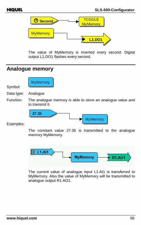
MyMemory���� Second���� Second
The value of MyMemory is inverted every second. Digital output L1.DO1 flashes every second.
Analogue memory
Symbol: MyMemoryMyMemory
Data type: Analogue
Function: The analogue memory is able to store an analogue value and to transmit it.
Examples: MyMemoryMyMemory
27.3527.35
The constant value 27.35 is transmitted to the analogue memory MyMemory.
The current value of analogue input L1.AI1 is transferred to MyMemory. Also the value of MyMemory will be transmitted to analogue output R1.AO1.

HIQUELHIQUELHIQUELHIQUEL SLS-500-Configurator
www.hiquel.com 59
MyMemoryMyMemoryL1.AI1L1.AI1
R1.AO1R1.AO1
MyMemoryMyMemory
22
//
The current value of analogue input L1.AI1 would be transmitted to MyMemory. Then the current value will be divided by 2 and transferred to analogue output R1.AO1.
IF rising edge SET analogue memory
Symbol:
In ����In ����ValueValue MyMemoryMyMemoryIn ����In ����ValueValue MyMemoryMyMemory
Data type: In Bit
Value Analogue
Function: When digital input In reads a rising edge, the value of input Value will be saved to MyMemory.
Example:
L1.AI1L1.AI1
In ����In ����ValueValue MyMemoryMyMemoryIn ����In ����ValueValue MyMemoryMyMemory
L1.DI4L1.DI4
With every rising edge of digital input L1.DI4, the existing value of analogue input L1.AI1 will be saved to MyMemory.

HIQUELHIQUELHIQUELHIQUEL SLS-500-Configurator
www.hiquel.com 60
IF falling edge SET analogue memory
Symbol:
In ����In ����ValueValue MyMemoryMyMemoryIn ����In ����ValueValue MyMemoryMyMemory
Data type: In Bit
Value Analogue
Function: When digital input In reads a falling edge, the existing value of input Value will be saved to MyMemory.
IF both edges SET analogue memory
Symbol:
In ���� ����In ���� ����
ValueValue MyMemoryMyMemoryIn ���� ����In ���� ����
ValueValue MyMemoryMyMemory
Data type: In Bit
Value Analogue
Function: When digital input In reads a rising or a falling edge, the value of input Value will be saved to MyMemory.
IF permanent high SET analogue memory
Symbol:
In==1In==1ValueValue MyMemoryMyMemoryIn==1In==1ValueValue MyMemoryMyMemory
Data type: In Bit
Value Analogue
Function: All the time digital input In reads the value 1, the value of input Value will be saved to MyMemory.
Example:

HIQUELHIQUELHIQUELHIQUEL SLS-500-Configurator
www.hiquel.com 61
-2.5-2.5
In==1In==1ValueValue MyMemoryMyMemoryIn==1In==1ValueValue MyMemoryMyMemory
STARTSTART
Just at program start up, the value –2.5 will be saved to the variable MyMemory.
IF permanent low SET analogue memory
Symbol:
In==0In==0ValueValue MyMemoryMyMemoryIn==0In==0ValueValue MyMemoryMyMemory
Data type: In Bit
Value Analogue
Function: All the time digital input In reads the value 0, the value of input Value will be saved to MyMemory.
Text memory
Symbol: MyMemoryMyMemory
Data type: Text
Function: The text memory is able to store a text value and to transmit it.
Examples:
The constant value will be saved to the text memory MyMemory.

HIQUELHIQUELHIQUELHIQUEL SLS-500-Configurator
www.hiquel.com 62
The text memory MyMemory is loaded with the constant value „Hallo „. After this the constant value „HIQUEL“ will be added to the content of MyMemory and saved to 2ndMemory. The result at 2ndMemory is „Hallo HIQUEL“
IF rising edge SET text memory
Symbol:
In ����In ����ValueValue MyMemoryMyMemoryIn ����In ����ValueValue MyMemoryMyMemory
Data type: In Bit
Value Text
Function: If digital input In reads a rising edge, the value of input Value will be transmitted to MyMemory.
IF falling edge SET text memory
Symbol:
In ����In ����ValueValue MyMemoryMyMemoryIn ����In ����ValueValue MyMemoryMyMemory
Data type: In Bit
Value Text
Function: If digital input In reads a falling edge, the value of input Value will be transmitted to MyMemory.

HIQUELHIQUELHIQUELHIQUEL SLS-500-Configurator
www.hiquel.com 63
IF both edges SET text memory
Symbol:
In ���� ����In ���� ����
ValueValue MyMemoryMyMemoryIn ���� ����In ���� ����
ValueValue MyMemoryMyMemory
Data type: In Bit
Value Text
Function: If digital input In reads a rising or falling edge, the value of input Value will be transmitted to MyMemory.
IF permanent high SET text memory
Symbol:
In==1In==1ValueValue MyMemoryMyMemoryIn==1In==1ValueValue MyMemoryMyMemory
Data type: In Bit
Value Text
Function: As long as digital input In reads the value 1, the value of input Value will be transmitted to MyMemory.
Example:
In==1In==1ValueValue MyMemoryMyMemoryIn==1In==1ValueValue MyMemoryMyMemory
STARTSTART
NowNow
The value „Now“ will only be saved to the variable MyMemory at program start up.
IF permanent low SET text memory
Symbol:
In==0In==0ValueValue MyMemoryMyMemoryIn==0In==0ValueValue MyMemoryMyMemory

HIQUELHIQUELHIQUELHIQUEL SLS-500-Configurator
www.hiquel.com 64
Data type: In Bit
Value Text
Function: As long as digital input In reads the value 0, the value of input Value will be saved to MyMemory.

HIQUELHIQUELHIQUELHIQUEL SLS-500-Configurator
www.hiquel.com 65
Binary operators There are a series of operators available for binary calculations. Choose Flow/Bit handling from the menu and select one of the following operators:
Binary operator: Binary AND
Symbol: &&
Data type: In1,In2 Bit
Out Bit
Function: This function calculates the AND-connection by using two input signals and delivers the result to the output.
In1 In2 Out
0 0 0
0 1 0
1 0 0
1 1 1
HIQUELHIQUELHIQUELHIQUEL SLS-500-Configurator
www.hiquel.com 66
Example:
&&
L1.DI1L1.DI1
L1.DI2L1.DI2L1.DO1L1.DO1
Digital output L1.DO1 is active, only if both digital inputs L1.DI1 and L1.DI2 are simultaneously active.
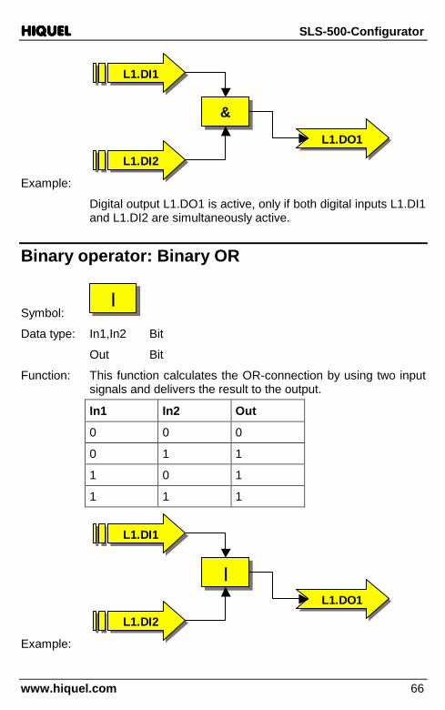
Binary operator: Binary OR
Symbol: ||
Data type: In1,In2 Bit
Out Bit
Function: This function calculates the OR-connection by using two input signals and delivers the result to the output.
In1 In2 Out
0 0 0
0 1 1
1 0 1
1 1 1
Example:
||
L1.DI1L1.DI1
L1.DI2L1.DI2L1.DO1L1.DO1

HIQUELHIQUELHIQUELHIQUEL SLS-500-Configurator
www.hiquel.com 67
The digital output L1.DO1 is active as soon as one of the two digital inputs L1.DI1 and L1.DI2 are active. If both are active the digital output will be active too.
Binary operator: Binary EXCLUSIVE OR
Symbol: ^̂
Data type: In1,In2 Bit
Out Bit
Function: This function calculates the EXCLUSIVE OR-connection by using two input signals and delivers the result to the output.
In1 In2 Out
0 0 0
0 1 1
1 0 1
1 1 0
Example:
^̂
L1.DI1L1.DI1
L1.DI2L1.DI2L1.DO1L1.DO1
Digital output L1.DO1 is active, as long as one of the two digital inputs L1.DI1 and L1.DI2 is active. If both are simultaneously active, the digital output will not be active.

HIQUELHIQUELHIQUELHIQUEL SLS-500-Configurator
www.hiquel.com 68
Binary operator: Binary NEGATION
Symbol: ~~
Data type: In Bit
Out Bit
Function: The current input value will be inverted.
In Out
0 1
1 0
Example:
L1.DI1L1.DI1
L1.DO1L1.DO1
~~
Digital output L1.DO1 always has the opposite signal status of digital input L1.DI1.
Binary operator: Rising edge
Symbol: ��������
Data type: In Bit
Out Bit
Function: If the input signal has a rising edge, this function is high for exactly one cycle.
Example:
In
Out
HIQUELHIQUELHIQUELHIQUEL SLS-500-Configurator
www.hiquel.com 69
��������
L1.DI1L1.DI1
L1.DO1L1.DO1
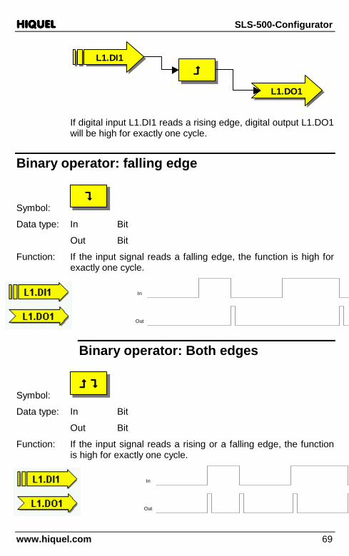
If digital input L1.DI1 reads a rising edge, digital output L1.DO1 will be high for exactly one cycle.
Binary operator: falling edge
Symbol: ��������
Data type: In Bit
Out Bit
Function: If the input signal reads a falling edge, the function is high for exactly one cycle.
In
Out
Binary operator: Both edges
Symbol: ���� �������� ����
Data type: In Bit
Out Bit
Function: If the input signal reads a rising or a falling edge, the function is high for exactly one cycle.
In
Out
HIQUELHIQUELHIQUELHIQUEL SLS-500-Configurator
www.hiquel.com 70
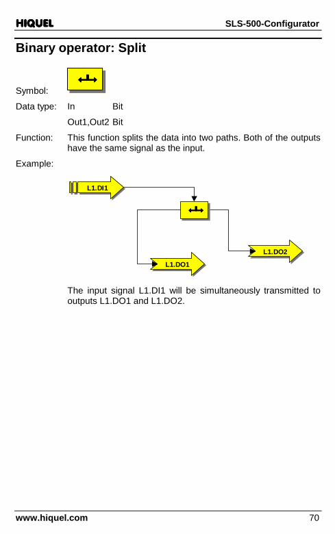
Binary operator: Split
Symbol: ����������������
Data type: In Bit
Out1,Out2 Bit
Function: This function splits the data into two paths. Both of the outputs have the same signal as the input.
Example:
L1.DI1L1.DI1
L1.DO2L1.DO2
����������������
L1.DO1L1.DO1
The input signal L1.DI1 will be simultaneously transmitted to outputs L1.DO1 and L1.DO2.

HIQUELHIQUELHIQUELHIQUEL SLS-500-Configurator
www.hiquel.com 71
Analogue operators The following operators are available for processing the analogue signals. Choose Flow/Analogue handling from the menu:
Analogue operator: Addition
Symbol: ++
Data type: In1,In2 Analogue
Out Analogue
Function: This function calculates the sum of the two analogue signals In1 and In2 and delivers the result to output Out.
HIQUELHIQUELHIQUELHIQUEL SLS-500-Configurator
www.hiquel.com 72
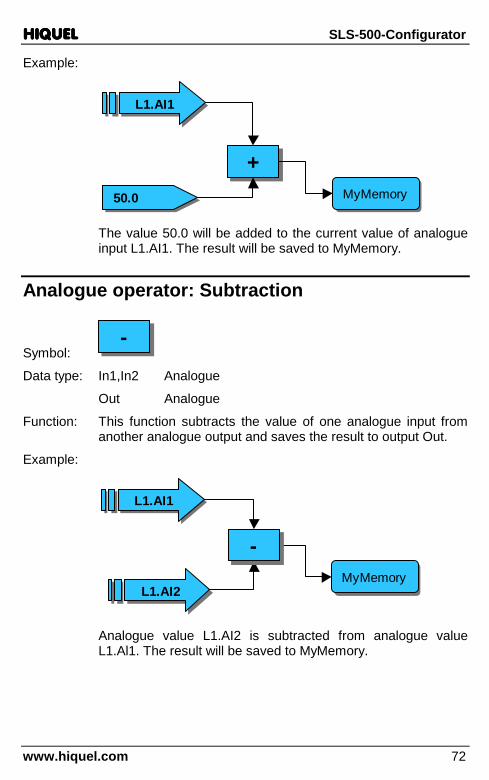
Example:
++
L1.AI1L1.AI1
50.050.0 MyMemoryMyMemory
The value 50.0 will be added to the current value of analogue input L1.AI1. The result will be saved to MyMemory.
Analogue operator: Subtraction
Symbol: --
Data type: In1,In2 Analogue
Out Analogue
Function: This function subtracts the value of one analogue input from another analogue output and saves the result to output Out.
Example:
L1.AI1L1.AI1
MyMemoryMyMemory
--
L1.AI2L1.AI2
Analogue value L1.AI2 is subtracted from analogue value L1.Al1. The result will be saved to MyMemory.

HIQUELHIQUELHIQUELHIQUEL SLS-500-Configurator
www.hiquel.com 73
Analogue operator: Multiplication
Symbol: **
Data type: In1,In2 Analogue
Out Analogue
Function: This function multiplies the two analogue signals In1 and In2 and delivers the result to output Out.
Example:
MyMemoryMyMemory
**
R1.POTI1R1.POTI1
0.10.1
The current potentiometer value R1.POTI1 is multiplied by the factor 0.1. The result will be saved to MyMemory. In this way you can get a potentiometer value between 0 and 10.
Analogue operator: Division
Symbol: //
Data type: In1,In2 Analogue
Out Analogue
Function: This function divides analogue signal In1 by In2 and delivers the result to output Out.

HIQUELHIQUELHIQUELHIQUEL SLS-500-Configurator
www.hiquel.com 74
Example:
MyMemoryMyMemory
R1.POTI1R1.POTI1
1010
//
The current potentiometer value R1.POTI1 is divided by 10. The result will be saved to MyMemory. In this way you can get a potentiometer value between 0 and 10.
Analogue operator: Modulo (read part of a value)
Symbol: %%
Data type: In1,In2 Analogue
Out Analogue
Function: This function transfers part of the analogue value (In1 divided by ln2) to output MyMemory.
Example:
MyMemoryMyMemory100100
%%
L1.AI1L1.AI1
The current analogue value of analogue input L1.AI1 is calculated with modulo 100. The result will be delivered to MyMemory.
1234.5678
34.5678

HIQUELHIQUELHIQUELHIQUEL SLS-500-Configurator
www.hiquel.com 75
Analogue operator: Shift left
Symbol: <<<<
Data type: In1,In2 Analogue
Out Analogue
Function: This function shifts the bits of input In1 to the left by In2 bits and delivers the result to output Out.
Example:
MyMemoryMyMemory33
L1.AI1L1.AI1
<<<<
The current analogue value of analogue input L1.AI1 will be shifted by 3 bits to the left. In this way the current value will be multiplied by 8. The result will be saved to MyMemory.
Analogue operator: Shift right
Symbol: >>>>
Data type: In1,In2 Analogue
Out Analogue
Function: This function shifts the bits of input In1 to the right by In2 bits and delivers the result to output Out.

HIQUELHIQUELHIQUELHIQUEL SLS-500-Configurator
www.hiquel.com 76
Example:
MyMemoryMyMemory11
L1.AI1L1.AI1
>>>>
The current analogue value of analogue input L1.AI1 would be shifted by 1 bit to the right. In this way the current value will be divided by two. The result will be saved to MyMemory.
Analogue operator: Greater than
Symbol: >>
Data type: In1,In2 Analogue
Out Bit
Function: This function compares the two analogue input signals In1 and In2. If In1 is greater than In2, the output will deliver a binary 1, otherwise a 0 will be transmitted.
Example:
50.050.0
L1.AI1L1.AI1
>>L1.DO1L1.DO1
If analogue input L1.AI1 is greater than 50.0, digital output L1.DO1 is activated.

HIQUELHIQUELHIQUELHIQUEL SLS-500-Configurator
www.hiquel.com 77
Analogue operator: Greater or equal
Symbol: >=>=
Data type: In1,In2 Analogue
Out Bit
Function: This function compares the analogue input signals In1 and In2. If In1 is greater than or equal to In2, the output will deliver a binary 1, otherwise a 0 will be transmitted.
Example:
50.050.0
L1.AI1L1.AI1
L1.DO1L1.DO1
>=>=
If analogue input L1.AI1 is greater than or equal to 50.0, digital output L1.DO1 will be active.
Analogue operator: Equal
Symbol: ==
Data type: In1,In2 Analogue
Out Bit
Function: This function compares the analogue input signals In1 and In2. If In1 is equal to In2, the output will deliver a binary 1, otherwise a 0 will be transmitted.

HIQUELHIQUELHIQUELHIQUEL SLS-500-Configurator
www.hiquel.com 78
Example:
50.050.0
L1.AI1L1.AI1
L1.DO1L1.DO1
==
If analogue input L1.AI1 has the value 50.000, the analogue output L1.DO1 will be activated.
Analogue operator: Not equal
Symbol: !=!=
Data type: In1,In2 Analogue
Out Bit
Function: This function compares the analogue input signals In1 and In2. If In1 is not equal to In2, the output delivers a binary 1; otherwise a 0 will be transmitted.
Example:
50.050.0
L1.AI1L1.AI1
L1.DO1L1.DO1
!=!=
If analogue input L1.AI1 does not have the value 50.000, digital output L1.DO1 will be activated.

HIQUELHIQUELHIQUELHIQUEL SLS-500-Configurator
www.hiquel.com 79
Analogue operator: Less or equal
Symbol: <=<=
Data type: In1,In2 Analogue
Out Bit
Function: This function compares the analogue input signals In1 and In2. If In1 is less than or equal to In2, the output delivers a binary 1, otherwise a 0 will be transmitted.
Example:
50.050.0
L1.AI1L1.AI1
L1.DO1L1.DO1
<=<=
If analogue input L1.AI1 has the value less than or equal to 50.000, digital output L1.DO1 will be activated.
Analogue operator: Less
Symbol: <<
Data type: In1,In2 Analogue
Out Bit
Function: This function compares the analogue input signals In1 and In2. If In1 is less than ln2, the output delivers a binary 1; otherwise a 0 will be transmitted.

HIQUELHIQUELHIQUELHIQUEL SLS-500-Configurator
www.hiquel.com 80
Example:
50.050.0
L1.AI1L1.AI1
L1.DO1L1.DO1
<<
If analogue input L1.AI1 has a value less than 50.000, digital output L1.DO1 will be activated.
Analogue operator: Logical AND
Symbol: &&&&
Data type: In1,In2 Analogue
Out Analogue
Function: This function compares the analogue input signals In1 and In2. If In1 is not equal to 0 and ln2 is not equal to 0, the output Out delivers a value that is unequal to 0 too. Otherwise the value 0 will be returned.
Example:
L1.AI1L1.AI1
&&&&
L1.AI2L1.AI2 MyMemoryMyMemory
If analogue inputs L1.AI1 and L1.AI2 are not equal to 0, the variable MyMemory will be unequal to 0 too.

HIQUELHIQUELHIQUELHIQUEL SLS-500-Configurator
www.hiquel.com 81
Analogue operator: Logical OR
Symbol: ||||
Data type: In1,In2 Analogue
Out Analogue
Function: This function compares the analogue input signals In1 and In2. If In1 is not equal to 0 or ln2 is not equal to 0, the output Out delivers a value that is unequal 0 too. Otherwise the value 0 will be returned.
Example:
L1.AI1L1.AI1
L1.AI2L1.AI2 MyMemoryMyMemory
||||
Only if at least one of the two analogue inputs L1.AI1 and L1.AI2 is unequal 0, the variable MyMemory will be unequal 0 too.
Analogue operator: Logical NOT
Symbol: !!
Data type: In Analogue
Out Analogue
Function: This function measures the analogue input signal In. If the input In has value 0, at output Out a value unequal 0 will be returned. If the input is unequal to 0, the value 0 will be returned.

HIQUELHIQUELHIQUELHIQUEL SLS-500-Configurator
www.hiquel.com 82
Example:
L1.AI1L1.AI1
MyMemoryMyMemory
!!
If analogue input L1.AI1 has exactly the value 0, the variable MyMemory will be unequal 0.
Analogue operator: Split
Symbol: ����������������
Data type: In Analogue
Out1,Out2 Analogue
Function: This function splits the input data into two paths. Both of the outputs will have the same signal as the input.
Example:
L1.AI1L1.AI1
MyMemoryMyMemory
����������������
R1.AO1R1.AO1
The input signal L1.AI1 will be simultaneously transmitted to analogue output L1.AO1 and to MyMemory.

HIQUELHIQUELHIQUELHIQUEL SLS-500-Configurator
www.hiquel.com 83
Text operators The following operators are available for processing texts. Choose Flow/Text handling from the menu to get to the following dialogue:
Text operator: Combine text
Symbol: ++
Data type: In1,In2 Text
Out Text
Function: This function combines the texts In1 and In2 to a new text and delivers it to output Out.
Example:
++
MyMemoryMyMemory
HalloHallo
WeltWelt
Both text parts „Hallo“ and „Welt“ will be assembled and saved to MyMemory as Hallo Welt (Hello world)
HIQUELHIQUELHIQUELHIQUEL SLS-500-Configurator
www.hiquel.com 84
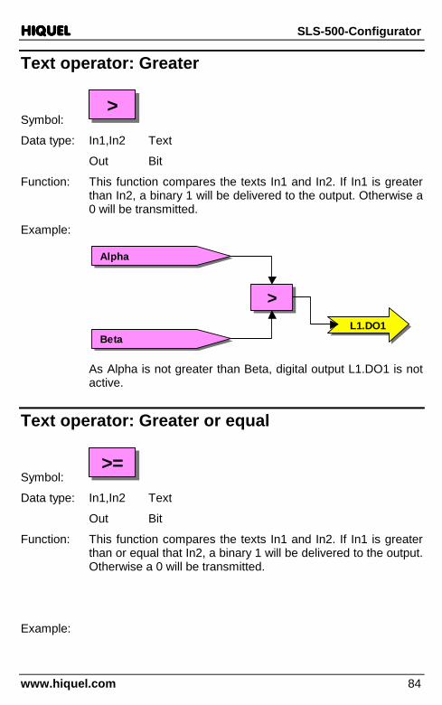
Text operator: Greater
Symbol: >>
Data type: In1,In2 Text
Out Bit
Function: This function compares the texts In1 and In2. If In1 is greater than In2, a binary 1 will be delivered to the output. Otherwise a 0 will be transmitted.
Example:
>>
AlphaAlpha
BetaBetaL1.DO1L1.DO1
As Alpha is not greater than Beta, digital output L1.DO1 is not active.
Text operator: Greater or equal
Symbol: >=>=
Data type: In1,In2 Text
Out Bit
Function: This function compares the texts In1 and In2. If In1 is greater than or equal that In2, a binary 1 will be delivered to the output. Otherwise a 0 will be transmitted.
Example:
HIQUELHIQUELHIQUELHIQUEL SLS-500-Configurator
www.hiquel.com 85
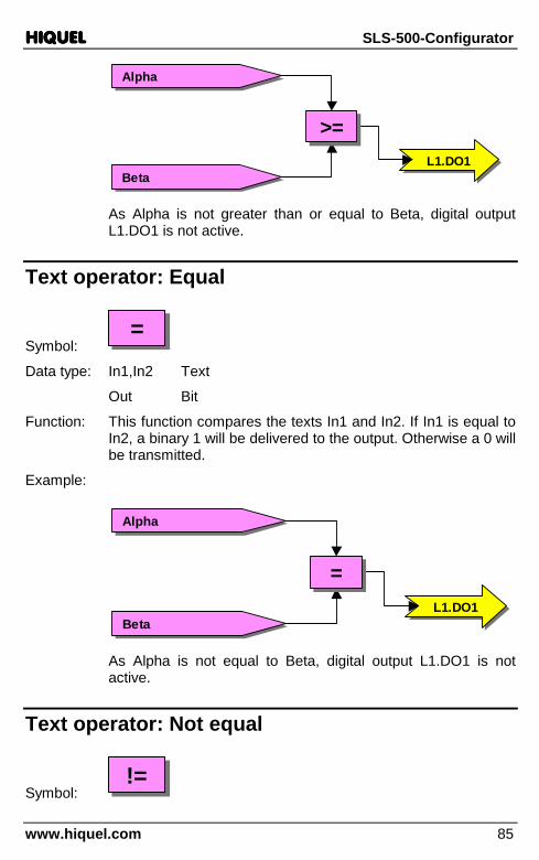
AlphaAlpha
BetaBetaL1.DO1L1.DO1
>=>=
As Alpha is not greater than or equal to Beta, digital output L1.DO1 is not active.
Text operator: Equal
Symbol: ==
Data type: In1,In2 Text
Out Bit
Function: This function compares the texts In1 and In2. If In1 is equal to In2, a binary 1 will be delivered to the output. Otherwise a 0 will be transmitted.
Example:
AlphaAlpha
BetaBetaL1.DO1L1.DO1
==
As Alpha is not equal to Beta, digital output L1.DO1 is not active.
Text operator: Not equal
Symbol: !=!=

HIQUELHIQUELHIQUELHIQUEL SLS-500-Configurator
www.hiquel.com 86
Data type: In1,In2 Text
Out Bit
Function: This function compares the texts In1 and In2. If In1 is not equal to In2, a binary 1 will be delivered to the output. Otherwise a 0 will be transmitted.
Example:
AlphaAlpha
BetaBetaL1.DO1L1.DO1
!=!=
As Alpha is not equal to Beta, digital output L1.DO1 is active.
Text operator: Less or equal
Symbol: <=<=
Data type: In1,In2 Text
Out Bit
Function: This function compares the texts In1 and In2. If In1 is less than or equal to In2, a binary 1 will be delivered to the output. Otherwise a 0 will be transmitted.
Example:

HIQUELHIQUELHIQUELHIQUEL SLS-500-Configurator
www.hiquel.com 87
AlphaAlpha
BetaBetaL1.DO1L1.DO1
<=<=
As Alpha is less than (or equal to) Beta, digital output L1.DO1 is active.
Text operator: Less
Symbol: <<
Data type: In1,In2 Text
Out Bit
Function: This function compares the texts In1 and In2. If In1 is less than In2, a binary 1 will be delivered to the output. Otherwise a 0 will be transmitted.
Example:
AlphaAlpha
BetaBetaL1.DO1L1.DO1
<<
As Alpha is less than Beta, digital output L1.DO1 is active.
Text operator: Split
Symbol: ����������������
Data type: In Text

HIQUELHIQUELHIQUELHIQUEL SLS-500-Configurator
www.hiquel.com 88
Out1,Out2 Text
Function: This function splits the text into two paths. Both of the outputs have the same signal as the input.
Example:
AlphaAlpha
����������������
1stMemory1stMemory 2ndMemory2ndMemory
The input signal L1.AI1 will be simultaneously delivered to analogue output L1.AO1 and to MyMemory.
Text operator: Sub String
Symbol:
TEXTSubString
TEXTSubString
InIn OutOut
StartStartLengthLength
TEXTSubString
TEXTSubString
InIn OutOut
StartStartLengthLength
Data type: In Text
Out Text
Start Analogue
Length Analogue
Function: This function delivers to output Out parts of character strings. The first letter of the string is defined in start and the number of characters is defined in length. The Start index starts counting with 0 therefore the first character of a full string is character 0.
Example:

HIQUELHIQUELHIQUELHIQUEL SLS-500-Configurator
www.hiquel.com 89
TEXTSubString
TEXTSubString
InIn OutOut
StartStartLengthLength
TEXTSubString
TEXTSubString
InIn OutOut
StartStartLengthLength
Hallo WeltHallo Welt
22
33
MyMemoryMyMemory
The text string llo will be saved to MyMemory!
Text operator: Left String
Symbol:
TEXTLeftString
TEXTLeftString
InIn OutOut
LengthLength
TEXTLeftString
TEXTLeftString
InIn OutOut
LengthLength
Data type: In Text
Out Text
Length Analogue
Function: This function delivers to output Out only the first X Length character of input In.
Example:
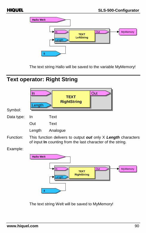
HIQUELHIQUELHIQUELHIQUEL SLS-500-Configurator
www.hiquel.com 90
Hallo WeltHallo Welt
55
MyMemoryMyMemoryTEXT
LeftStringTEXT
LeftString
InIn OutOut
LengthLength
TEXTLeftString
TEXTLeftString
InIn OutOut
LengthLength
The text string Hallo will be saved to the variable MyMemory!
Text operator: Right String
Symbol:
TEXTRightString
TEXTRightString
InIn OutOut
LengthLength
TEXTRightString
TEXTRightString
InIn OutOut
LengthLength
Data type: In Text
Out Text
Length Analogue
Function: This function delivers to output out only X Length characters of input In counting from the last character of the string.
Example:
Hallo WeltHallo Welt
44
MyMemoryMyMemoryTEXT
RightStringTEXT
RightString
InIn OutOut
LengthLength
TEXTRightString
TEXTRightString
InIn OutOut
LengthLength
The text string Welt will be saved to MyMemory!

HIQUELHIQUELHIQUELHIQUEL SLS-500-Configurator
www.hiquel.com 91
Text operator: String Length
Symbol:
TEXTStringLength
TEXTStringLength
InIn OutOutTEXT
StringLengthTEXT
StringLength
InIn OutOut
Data type: In Text
Out Analogue
Function: This function delivers the number of characters included in the text string of input ln to output Out.
Example:
Hallo WeltHallo Welt
TEXTStringLength
TEXTStringLength
InIn OutOutTEXT
StringLengthTEXT
StringLength
InIn OutOutMyMemoryMyMemory
The length of the text string Hallo Welt will be saved to MyMemory. These are exactly 10 characters!

HIQUELHIQUELHIQUELHIQUEL SLS-500-Configurator
www.hiquel.com 92
Counter This chapter deals with the integrated counters.
To insert a counter choose Flow/Counter. The following dialogue will appear:
Counter: Count Up
Symbol:
In ����In ����ValueValue MyCounterMyCounter
COUNT UPCOUNT UP
In ����In ����ValueValue MyCounterMyCounter
COUNT UPCOUNT UP
Data type: In Bit
Value Analogue
Function: When input ln reads a rising edge, this function adds the value Value to the value of the analogue memory MyCounter. The use of Input Value is optional. If the input value remains unused, the value 1.000 will be added.

HIQUELHIQUELHIQUELHIQUEL SLS-500-Configurator
www.hiquel.com 93
Example:
In ����In ����ValueValue MyCounterMyCounter
COUNT UPCOUNT UP
In ����In ����ValueValue MyCounterMyCounter
COUNT UPCOUNT UP
L1.DI1L1.DI1
Every time digital input L1.DI1 detects a rising edge, the analogue memory MyCounter will be increased by one.
In ����In ����ValueValue MyCounterMyCounter
COUNT UPCOUNT UP
In ����In ����ValueValue MyCounterMyCounter
COUNT UPCOUNT UPL1.DI2L1.DI2
2.452.45
Every time digital input L1.DI2 detects a rising edge, the value 2.45 will be added to MyCounter.
Counter: Count Down
Symbol:
In ����In ����ValueValue MyCounterMyCounter
COUNT DOWNCOUNT DOWN
In ����In ����ValueValue MyCounterMyCounter
COUNT DOWNCOUNT DOWN
Data type: In Bit
Value Analogue
Function: When input ln reads a rising edge, this function subtracts the value Value from the value of the analogue memory MyCounter. The use of Input Value is optional. If the input value remains unused, the value 1.000 will be subtracted.

HIQUELHIQUELHIQUELHIQUEL SLS-500-Configurator
www.hiquel.com 94
Example:
L1.DI1L1.DI1
In ����In ����ValueValue MyCounterMyCounter
COUNT DOWNCOUNT DOWN
In ����In ����ValueValue MyCounterMyCounter
COUNT DOWNCOUNT DOWN
Every time digital input L1.DI1 detects a rising edge, the analogue memory MyCounter will be reduced by one.
L1.DI2L1.DI2
2.452.45 In ����In ����ValueValue MyCounterMyCounter
COUNT DOWNCOUNT DOWN
In ����In ����ValueValue MyCounterMyCounter
COUNT DOWNCOUNT DOWN
Every time digital input L1.DI2 detects a rising edge, the value 2.45 will be subtracted from MyCounter.
Counter: Count Set
Symbol:
In ����In ����ValueValue MyCounterMyCounter
COUNT SETCOUNT SET
In ����In ����ValueValue MyCounterMyCounter
COUNT SETCOUNT SET
Data type: In Bit
Value Analogue
Function: If input ln detects a rising edge, the analogue memory MyCounter will be set to value Value. Input Value is optional. If it stays unused the value 0.000 will be set.

HIQUELHIQUELHIQUELHIQUEL SLS-500-Configurator
www.hiquel.com 95
Example:
L1.DI1L1.DI1
In ����In ����ValueValue MyCounterMyCounter
COUNT SETCOUNT SET
In ����In ����ValueValue MyCounterMyCounter
COUNT SETCOUNT SET
Every time digital input L1.DI1 detects a rising edge, the analogue memory MyCounter will be reset to 0.
L1.DI2L1.DI2
100100 In ����In ����ValueValue MyCounterMyCounter
COUNT SETCOUNT SET
In ����In ����ValueValue MyCounterMyCounter
COUNT SETCOUNT SET
Every time digital input L1.DI2 detects a rising edge, the analogue memory MyCounter will be set to 100.000.
Counter: Count up with limit
Symbol:
Data type: In Bit
Value Analogue
Limit Analogue
Function: If input ln detects a rising edge, the value Value will be add to the analogue memory My Counter. Input Value is optional. If it stays unused the value 1.000 will be added.

HIQUELHIQUELHIQUELHIQUEL SLS-500-Configurator
www.hiquel.com 96
The process can be repeated as long as the Limit for the analogue input is reached. If the Limit stays unused, no limit will be set.
Example:
Every time a rising edge is detected at digital input L1.DI1 the analogue memory MyCounter will be increased by one.
With every rising edge at digital input L1.DI2 the value 1 will be added to MyCounter, as long as MyCounter reaches the value 5.
Counter: Count down with limit
Symbol:
Data type: In Bit
Value Analogue
Limit Analogue
Function: With every rising edge at input ln the value Value will be subtracted from MyCounter. The input Value is optional.

HIQUELHIQUELHIQUELHIQUEL SLS-500-Configurator
www.hiquel.com 97
If it stays unused the value 1.000 will be subtracted. The process can be repeated as long as the Limit for the analogue input is reached. If the Limit stays unused, no limit will be set.
Example:
Every time a rising edge is detected at digital input L1.DI1 the analogue memory MyCounter will be lowered by 1.
With every rising edge at digital input L1.DI2 the value 1 will be subtracted from MyCounter as long as MyCounter reaches the value 10.
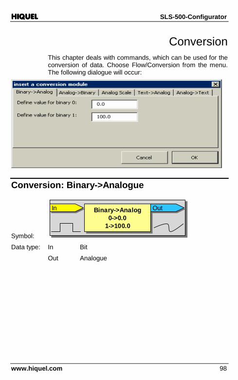
HIQUELHIQUELHIQUELHIQUEL SLS-500-Configurator
www.hiquel.com 98
Conversion This chapter deals with commands, which can be used for the conversion of data. Choose Flow/Conversion from the menu. The following dialogue will occur:
Conversion: Binary->Analogue
Symbol:
InIn Binary->Analog0->0.0
1->100.0
Binary->Analog0->0.0
1->100.0
OutOutInIn Binary->Analog0->0.0
1->100.0
Binary->Analog0->0.0
1->100.0
OutOut
Data type: In Bit
Out Analogue
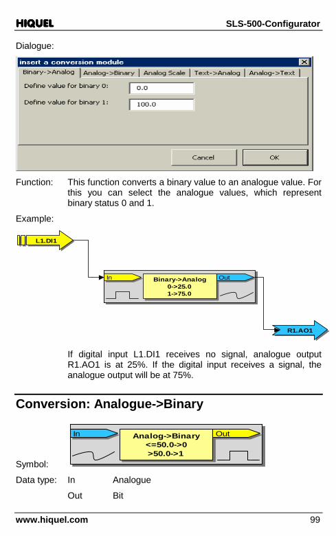
HIQUELHIQUELHIQUELHIQUEL SLS-500-Configurator
www.hiquel.com 99
Dialogue:
Function: This function converts a binary value to an analogue value. For
this you can select the analogue values, which represent binary status 0 and 1.
Example:
InIn Binary->Analog0->25.01->75.0
Binary->Analog0->25.01->75.0
OutOutInIn Binary->Analog0->25.01->75.0
Binary->Analog0->25.01->75.0
OutOut
L1.DI1L1.DI1
R1.AO1R1.AO1
If digital input L1.DI1 receives no signal, analogue output R1.AO1 is at 25%. If the digital input receives a signal, the analogue output will be at 75%.
Conversion: Analogue->Binary
Symbol:
InIn Analog->Binary<=50.0->0>50.0->1
Analog->Binary<=50.0->0>50.0->1
OutOutInIn Analog->Binary<=50.0->0>50.0->1
Analog->Binary<=50.0->0>50.0->1
OutOut
Data type: In Analogue
Out Bit

HIQUELHIQUELHIQUELHIQUEL SLS-500-Configurator
www.hiquel.com 100
Dialogue:
Function: This function converts an analogue value to a binary value. For this the analogue value will function by using a threshold. If the existing analogue value at input ln is below the threshold or exactly on the threshold value (for example 50.0), output Out will deliver the binary value 0. If the input value is above the threshold, the binary value 1 will be delivered.
Example:
InIn Analog->Binary<=50.0->0>50.0->1
Analog->Binary<=50.0->0>50.0->1
OutOutInIn Analog->Binary<=50.0->0>50.0->1
Analog->Binary<=50.0->0>50.0->1
OutOut
R1.POTI1R1.POTI1
R1.DO1R1.DO1
If the value set at potentiometer R1.POTI1 is below or equal 50.0, digital output R1.DO1 will be switched off. If the value is higher than 50%, the digital output will be switched on.

HIQUELHIQUELHIQUELHIQUEL SLS-500-Configurator
www.hiquel.com 101
Conversion: Analogue Scale
Symbol:
InIn Scale0.0;100.0
10;25
Scale0.0;100.0
10;25
OutOutInIn Scale0.0;100.0
10;25
Scale0.0;100.0
10;25
OutOut
Data type: In Analogue
Out Analogue
Dialogue:
Function: This function converts the analogue input signal that is within
the input range (0.0-100.0) to the analogue output signal with a different output range (10.0-25.0).
R1.POTI1R1.POTI1
InIn Scale0.0;100.0
10;25
Scale0.0;100.0
10;25
OutOutInIn Scale0.0;100.0
10;25
Scale0.0;100.0
10;25
OutOut
R1.AO1R1.AO1

HIQUELHIQUELHIQUELHIQUEL SLS-500-Configurator
www.hiquel.com 102
If potentiometer R1.POTI1 has the value 0%, the value 10% will be transmitted by analogue output R1.AO1. If the potentiometer has the value 100%, the value 25% will be transmitted by the analogue output.
Conversion: Text->Analogue
Symbol:
InIn
Text->AnalogText->AnalogOutOut
13.7603
InIn
Text->AnalogText->AnalogOutOut
13.7603
Data type: In Text
Out Analogue
Dialogue:
Function: This function converts a text string at input In to a
corresponding analogue value at output Out.
Example:
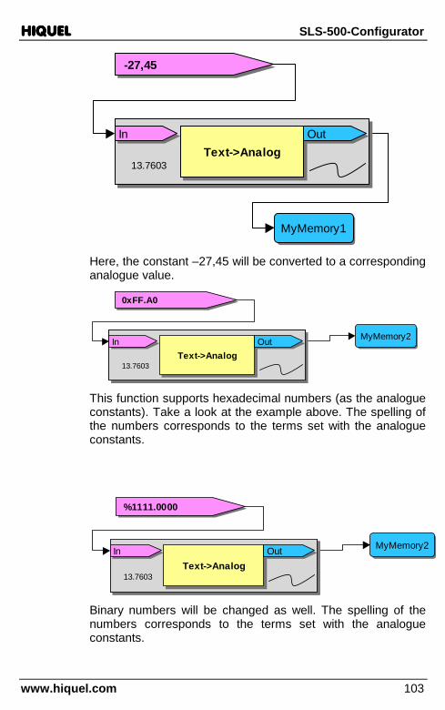
HIQUELHIQUELHIQUELHIQUEL SLS-500-Configurator
www.hiquel.com 103
InIn
Text->AnalogText->AnalogOutOut
13.7603
InIn
Text->AnalogText->AnalogOutOut
13.7603
-27,45-27,45
MyMemory1MyMemory1
Here, the constant –27,45 will be converted to a corresponding analogue value.
InIn
Text->AnalogText->AnalogOutOut
13.7603
InIn
Text->AnalogText->AnalogOutOut
13.7603
0xFF.A00xFF.A0
MyMemory2MyMemory2
This function supports hexadecimal numbers (as the analogue constants). Take a look at the example above. The spelling of the numbers corresponds to the terms set with the analogue constants.
InIn
Text->AnalogText->AnalogOutOut
13.7603
InIn
Text->AnalogText->AnalogOutOut
13.7603
%1111.0000%1111.0000
MyMemory2MyMemory2
Binary numbers will be changed as well. The spelling of the numbers corresponds to the terms set with the analogue constants.

HIQUELHIQUELHIQUELHIQUEL SLS-500-Configurator
www.hiquel.com 104
Conversion: Analogue->Text
Symbol:
InInAnalog->Text
Format:999.000Analog->Text
Format:999.000
OutOut
13.7603
InInAnalog->Text
Format:999.000Analog->Text
Format:999.000
OutOut
13.7603
Data type: In Analogue
Out Text:
Dialogue:
Function: This function changes the analogue input signal into a
formatted text value. For this the adjusted format will be used. Also refer to chapter format characters.
Example:
InInAnalog->Text
Format:000.000Analog->Text
Format:000.000
OutOut
13.7603
InInAnalog->Text
Format:000.000Analog->Text
Format:000.000
OutOut
13.7603
L1.AI1L1.AI1
MyMemoryMyMemory
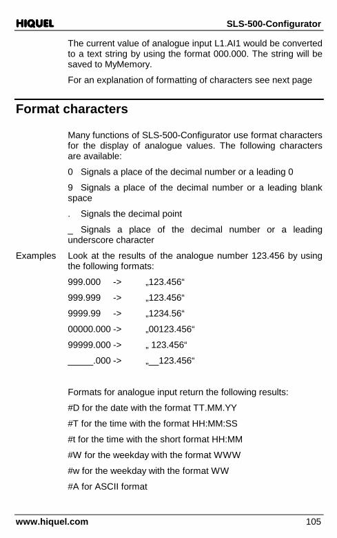
HIQUELHIQUELHIQUELHIQUEL SLS-500-Configurator
www.hiquel.com 105
The current value of analogue input L1.AI1 would be converted to a text string by using the format 000.000. The string will be saved to MyMemory.
For an explanation of formatting of characters see next page
Format characters
Many functions of SLS-500-Configurator use format characters for the display of analogue values. The following characters are available:
0 Signals a place of the decimal number or a leading 0
9 Signals a place of the decimal number or a leading blank space
. Signals the decimal point
_ Signals a place of the decimal number or a leading underscore character
Examples Look at the results of the analogue number 123.456 by using the following formats:
999.000 -> „123.456“
999.999 -> „123.456“
9999.99 -> „1234.56“
00000.000 -> „00123.456“
99999.000 -> „ 123.456“
_____.000 -> „__123.456“
Formats for analogue input return the following results:
#D for the date with the format TT.MM.YY
#T for the time with the format HH:MM:SS
#t for the time with the short format HH:MM
#W for the weekday with the format WWW
#w for the weekday with the format WW
#A for ASCII format
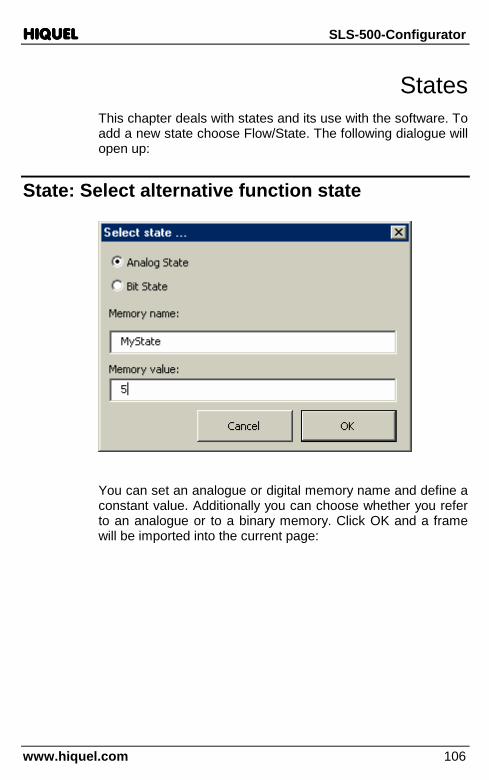
HIQUELHIQUELHIQUELHIQUEL SLS-500-Configurator
www.hiquel.com 106
States This chapter deals with states and its use with the software. To add a new state choose Flow/State. The following dialogue will open up:
State: Select alternative function state
You can set an analogue or digital memory name and define a constant value. Additionally you can choose whether you refer to an analogue or to a binary memory. Click OK and a frame will be imported into the current page:
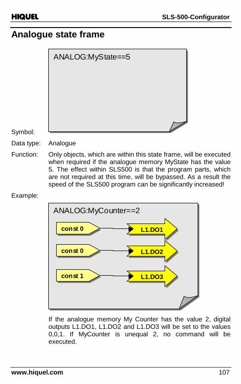
HIQUELHIQUELHIQUELHIQUEL SLS-500-Configurator
www.hiquel.com 107
Analogue state frame
Symbol:
ANALOG:MyState==5ANALOG:MyState==5
Data type: Analogue
Function: Only objects, which are within this state frame, will be executed when required if the analogue memory MyState has the value 5. The effect within SLS500 is that the program parts, which are not required at this time, will be bypassed. As a result the speed of the SLS500 program can be significantly increased!
Example:
ANALOG:MyCounter==2ANALOG:MyCounter==2
L1.DO1L1.DO1const 0const 0
L1.DO2L1.DO2const 0const 0
L1.DO3L1.DO3const 1const 1
If the analogue memory My Counter has the value 2, digital outputs L1.DO1, L1.DO2 and L1.DO3 will be set to the values 0,0,1. If MyCounter is unequal 2, no command will be executed.

HIQUELHIQUELHIQUELHIQUEL SLS-500-Configurator
www.hiquel.com 108
Binary state
Symbol:
DIGITAL:MyState==1DIGITAL:MyState==1
DIGITAL:MyState==0DIGITAL:MyState==0
Data type: Bit
Function: Only objects, which are within the state frame, will be executed if the binary memory MyState has the value 0 or 1. The effect within SLS500 is that the parts of the program that are nor required will be bypassed. As a result the speed of the SLS500 program can be significantly increased!
Example:
DIGITAL:MyState==1DIGITAL:MyState==1
L1.DO1L1.DO1const 0const 0
L1.DO2L1.DO2const 0const 0
L1.DO3L1.DO3const 1const 1
If the binary memory MyState has the value 1, digital outputs L1.DO1, L1.DO2 and L1.DO3 will be set to the values 0,0,1. If MyState is equal 0, no command will be executed.
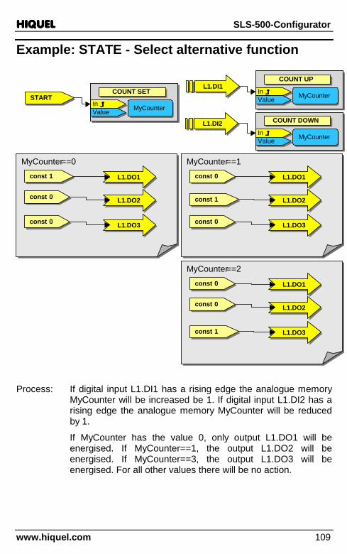
HIQUELHIQUELHIQUELHIQUEL SLS-500-Configurator
www.hiquel.com 109
Example: STATE - Select alternative function
MyCounter==0 MyCounter==0
START START In ���� In ���� Value Value MyCounterMyCounter
COUNT SETCOUNT SET
In ���� In ���� Value Value MyCounterMyCounter
COUNT SETCOUNT SET In ����In ����ValueValue MyCounter MyCounter
COUNT UP COUNT UP In ����In ����ValueValue MyCounter MyCounter
COUNT UP COUNT UP L1.DI1L1.DI1
const 1 const 1 L1.DO1L1.DO1
L1.DO2L1.DO2
L1.DO3L1.DO3
MyCounter==1MyCounter==1
L1.DO1 L1.DO1
const 1const 1 L1.DO2 L1.DO2
L1.DO3 L1.DO3
MyCounter==2MyCounter==2
L1.DO1 L1.DO1
L1.DO2 L1.DO2
const 1const 1 L1.DO3 L1.DO3
In ����In ����ValueValue MyCounter MyCounter
COUNT DOWN COUNT DOWN In ����In ����ValueValue MyCounter MyCounter
COUNT DOWN COUNT DOWN L1.DI2L1.DI2
const 0 const 0
const 0 const 0
const 0const 0
const 0const 0
const 0const 0
const 0const 0
Process: If digital input L1.DI1 has a rising edge the analogue memory MyCounter will be increased be 1. If digital input L1.DI2 has a rising edge the analogue memory MyCounter will be reduced by 1.
If MyCounter has the value 0, only output L1.DO1 will be energised. If MyCounter==1, the output L1.DO2 will be energised. If MyCounter==3, the output L1.DO3 will be energised. For all other values there will be no action.
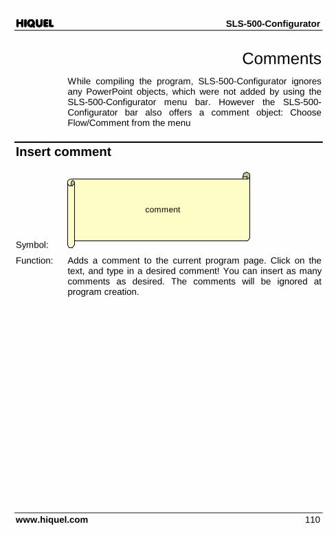
HIQUELHIQUELHIQUELHIQUEL SLS-500-Configurator
www.hiquel.com 110
Comments While compiling the program, SLS-500-Configurator ignores any PowerPoint objects, which were not added by using the SLS-500-Configurator menu bar. However the SLS-500-Configurator bar also offers a comment object: Choose Flow/Comment from the menu
Insert comment
Symbol:
comment
Function: Adds a comment to the current program page. Click on the text, and type in a desired comment! You can insert as many comments as desired. The comments will be ignored at program creation.

HIQUELHIQUELHIQUELHIQUEL SLS-500-Configurator
www.hiquel.com 111
Symbolic groups Basically SLS-500-Configurator ignores all PowerPoint objects, which have not been put in by the SLS-500-Configurator menu bar, while translating the program. The object for group creation is also available in the SLS-500-Configurator bar: Choose Symbolic group from the menu.
Create symbolic groups
Symbol:
Function: Inserts a background to the current program page. Click on the text and type in the desired title for the group! Now drag and drop those objects, which should build one group into the field. You can create as many symbolic groups as you want on one page. Nothing will change in the program creation.
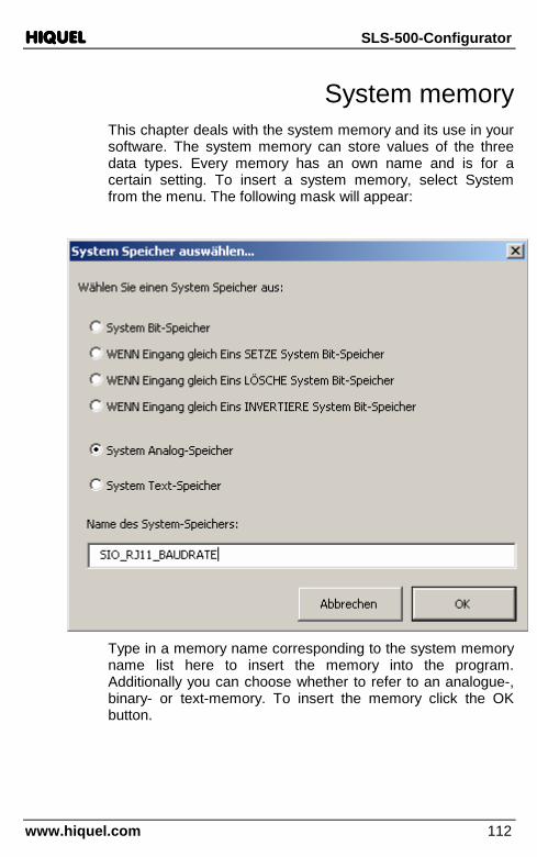
HIQUELHIQUELHIQUELHIQUEL SLS-500-Configurator
www.hiquel.com 112
System memory This chapter deals with the system memory and its use in your software. The system memory can store values of the three data types. Every memory has an own name and is for a certain setting. To insert a system memory, select System from the menu. The following mask will appear:
Type in a memory name corresponding to the system memory name list here to insert the memory into the program. Additionally you can choose whether to refer to an analogue-, binary- or text-memory. To insert the memory click the OK button.
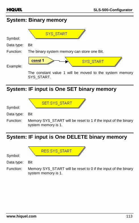
HIQUELHIQUELHIQUELHIQUEL SLS-500-Configurator
www.hiquel.com 113
System: Binary memory
Symbol:
Data type: Bit
Function: The binary system memory can store one Bit.
Example:
The constant value 1 will be moved to the system memory SYS_START.
System: IF input is One SET binary memory
Symbol:
Data type: Bit
Function: Memory SYS_START will be reset to 1 if the input of the binary system memory is 1.
System: IF input is One DELETE binary memory
Symbol:
Data type: Bit
Function: Memory SYS_START will be reset to 0 if the input of the binary system memory is 1.
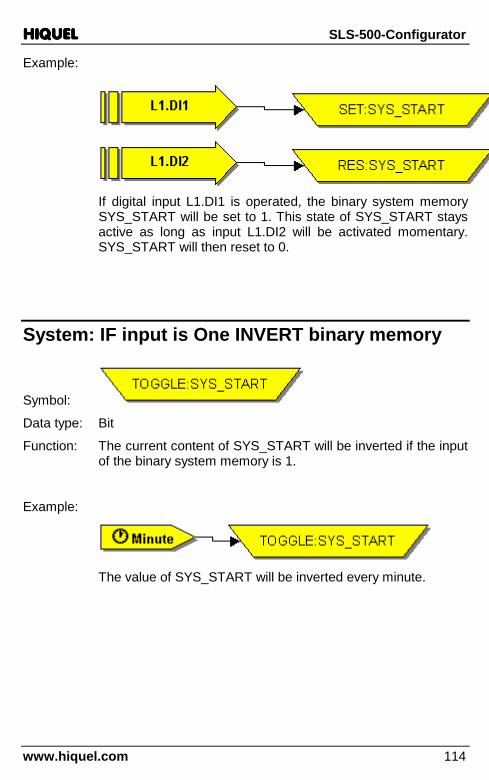
HIQUELHIQUELHIQUELHIQUEL SLS-500-Configurator
www.hiquel.com 114
Example:
If digital input L1.DI1 is operated, the binary system memory SYS_START will be set to 1. This state of SYS_START stays active as long as input L1.DI2 will be activated momentary. SYS_START will then reset to 0.
System: IF input is One INVERT binary memory
Symbol:
Data type: Bit
Function: The current content of SYS_START will be inverted if the input of the binary system memory is 1.
Example:
The value of SYS_START will be inverted every minute.

HIQUELHIQUELHIQUELHIQUEL SLS-500-Configurator
www.hiquel.com 115
System: Analogue memory
Symbol:
Data type: Analogue
Function: The analogue memory can store an analogue value.
Example:
The constant value 19200 will be moved to the analogue system memory SIO_RJ11_BAUDRATE.
System: Text memory
Symbol:
Data type: Text
Function: The text memory can store a text value.
Example:
The constant value „MI 08.01.03 15:31:30“ will be moved to text memory CLOCK.
!Important!: Mind the character string and the character length when entering the characters! Also blank character will be considered.

HIQUELHIQUELHIQUELHIQUEL SLS-500-Configurator
www.hiquel.com 116
System: System variable table
All names of the system memory have to by used with the same format as in the table for programming. That means that all characters have to type in with block capitals. Mind the gap and the underlines!
Data type Name Example String-length
binary ENCODER_XY 1 or 0 1
binary PWM 1 or 0 1
binary ENCODER 1 or 0 1
analogue SYS_CYCLETIME
analogue SYS_SYSTIME
analogue SYS_CYCLEMAX
analogue SYS_SYSMAX
analogue SIO_RJ11_BAUDRATE 19200 max. 5
analogue ENCODER_X
analogue ENCODER_Y
analogue PWM_DO1
analogue PWM_DO2
analogue PWM_DO3
analogue PWM_DO4
analogue PWM_DO5
analogue PWM_DO6
analogue ENCODER
analogue COUNTER_A
analogue COUNTER_B
analogue SPEED_A
analogue SPEED_B
text CLOCK WE 08.01.03 15:31:30 20

HIQUELHIQUELHIQUELHIQUEL SLS-500-Configurator
www.hiquel.com 117
Incremental Encoder The Models HIQUEL-SLS500-R-24V and HIQUEL-SLS500-S-24V use digital inputs Di5-Di8 to receive the signal from the incremental encoder/s The models HIQUEL-SLS500-R-24V and HIQUEL-SLS500-S-24V can each have two incremental encoders connected (Di5/6 – Di7/8).
The Incremental Encoder
An Incremental Encoder transmits signals over two wires. These are called channel A and channel B. The speed of the incremental encoder in which the impulses are sent, is called “Line”.
To process the data in the SLS-500 requires a procedure, which transforms the impulses to a position. This procedure is called „4-times evaluation“, or “quadrature control”.
t
0
24 V
0
24 V
A
B

HIQUELHIQUELHIQUELHIQUEL SLS-500-Configurator
www.hiquel.com 118
In the diagram A and B represent the two channel inputs from an Encoder. The „quadrature control“ gives information about the direction and the actual position of the encoder. e. g. The encoder has a resolution of 1000 lines, then it is sending 1000 A impulses and 1000 B impulses per revolution. The SLS-500 is converting this into 4000 impulse internally, A and B rising edge and A and B falling edge impulses. Therefore SLS-500 processes 1 encoder revolution into 4000 impulses
NOTE The HIQUEL-SLS-500-Base controller can process 5000
edges per second maximum, combined Di´s 5-8 (2 encoders)
Programming an incremental encoder
In SLS-500-Configurator, encoders are initialised on a binary system variable which is set to 1 using a bit-constant. This binary system-variable must only have the name „ENCODER_XY“ This is case sensitive. Select System from the menu “Flow > System. The following box will appear:

HIQUELHIQUELHIQUELHIQUEL SLS-500-Configurator
www.hiquel.com 119
From the list select „System binary Memory“ and in the box type „ENCODER_XY“ then click OK.
Symbol:
Data type: Bit
When the binary-system-variable is initialised, you must set the analogue-system-variable „ENCODER_X“ and „ENCODER_Y“ to 0 to delete them. In contrast to „ENCODER_XY“ this is not a binary-system-variable but an analogue-system-variable. The input is case sensitive. (ENCODER_X, ENCODER_Y) Here they are set to 0:
The value of a incremental encoder could also be stored in an analogue memory:
An incremental-encoder could also be set to a certain value:
const 1const 1 ENCODER_XYENCODER_XY
00
00
ENCODER_XENCODER_X
ENCODER_YENCODER_Y
ENCODER_XENCODER_X MyVar1MyVar1
ENCODER_XENCODER_XMyVar1MyVar1
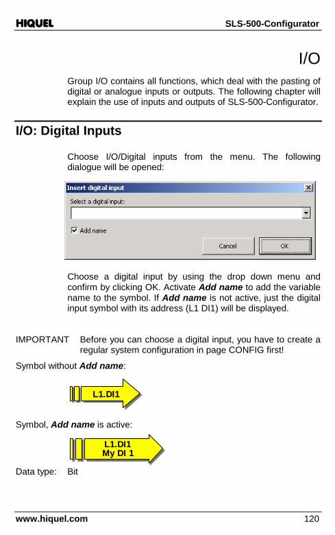
HIQUELHIQUELHIQUELHIQUEL SLS-500-Configurator
www.hiquel.com 120
L1.DI1My DI 1L1.DI1My DI 1
I/O Group I/O contains all functions, which deal with the pasting of digital or analogue inputs or outputs. The following chapter will explain the use of inputs and outputs of SLS-500-Configurator.
I/O: Digital Inputs
Choose I/O/Digital inputs from the menu. The following dialogue will be opened:
Choose a digital input by using the drop down menu and confirm by clicking OK. Activate Add name to add the variable name to the symbol. If Add name is not active, just the digital input symbol with its address (L1 DI1) will be displayed.
IMPORTANT Before you can choose a digital input, you have to create a regular system configuration in page CONFIG first!
Symbol without Add name:
L1.DI1L1.DI1
Symbol, Add name is active:
Data type: Bit

HIQUELHIQUELHIQUELHIQUEL SLS-500-Configurator
www.hiquel.com 121
Function: This function adds a digital input. Digital inputs can be a starting point of connections. You will also find all digital outputs in the list to process the current status of the outputs.
Examples:
The current state of digital input L1.DI1 will be transmitted to the output.
The current state of digital output L1.DO1 will be transmitted to MyMemory.
I/O: Digital Outputs
Choose I/O/Digital outputs to get to the following dialogue:
Choose a digital output by using the drop down menu and confirm by clicking OK. Activate Add name to add the variable name to the symbol. If Add name is not active, only the digital output symbol with its address (L1 DO1) will be displayed.
Additionally you can choose one of four functions of the output:
Normal output: The output always takes the value of the incoming connection.

HIQUELHIQUELHIQUELHIQUEL SLS-500-Configurator
www.hiquel.com 122
SET output: When the connection is 1, the output will be set to High. When the connection returns to 0, the value of the output stays unchanged.
RESET output: When the connection is 1, the output will be set to Low. If the connection is 0, the value of the output stays unchanged.
TOGGLE output: When the connection is 1 for the first time, the output will energise. When the connection becomes 0, the output remains energised. When the connection is 1 for the second time the output de-energises. When the connection becomes 0 for the second time the output remains de-energised, and so on…… (Can be used as a bi-stable function)
IMPORTANT Before you can choose a digital input, you have to create a regular system configuration in page CONFIG first!
Symbol without Add name:
L1.DO1L1.DO1
Symbol, Add name is active:
Symbol for function SET:
SET:L1.DO1Motor A
SET:L1.DO1Motor A
Symbol for function RESET:
RESET:L1.DO1Motor A
RESET:L1.DO1Motor A
Symbol for function TOGGLE:
L1.DO1My DO1L1.DO1My DO1
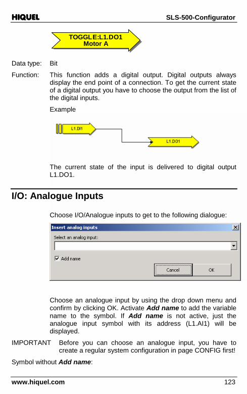
HIQUELHIQUELHIQUELHIQUEL SLS-500-Configurator
www.hiquel.com 123
TOGGLE:L1.DO1Motor A
TOGGLE:L1.DO1Motor A
Data type: Bit
Function: This function adds a digital output. Digital outputs always display the end point of a connection. To get the current state of a digital output you have to choose the output from the list of the digital inputs.
Example
The current state of the input is delivered to digital output L1.DO1.
I/O: Analogue Inputs
Choose I/O/Analogue inputs to get to the following dialogue:
Choose an analogue input by using the drop down menu and confirm by clicking OK. Activate Add name to add the variable name to the symbol. If Add name is not active, just the analogue input symbol with its address (L1.AI1) will be displayed.
IMPORTANT Before you can choose an analogue input, you have to create a regular system configuration in page CONFIG first!
Symbol without Add name:
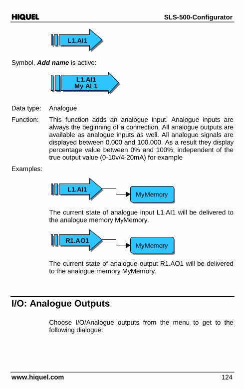
HIQUELHIQUELHIQUELHIQUEL SLS-500-Configurator
www.hiquel.com 124
L1.AI1L1.AI1
Symbol, Add name is active:
Data type: Analogue
Function: This function adds an analogue input. Analogue inputs are always the beginning of a connection. All analogue outputs are available as analogue inputs as well. All analogue signals are displayed between 0.000 and 100.000. As a result they display percentage value between 0% and 100%, independent of the true output value (0-10v/4-20mA) for example
Examples:
L1.AI1L1.AI1MyMemoryMyMemory
The current state of analogue input L1.AI1 will be delivered to the analogue memory MyMemory.
MyMemoryMyMemoryR1.AO1R1.AO1
The current state of analogue output R1.AO1 will be delivered to the analogue memory MyMemory.
I/O: Analogue Outputs
Choose I/O/Analogue outputs from the menu to get to the following dialogue:
L1.AI1My AI 1L1.AI1
My AI 1

HIQUELHIQUELHIQUELHIQUEL SLS-500-Configurator
www.hiquel.com 125
Choose an analogue output by using the drop down menu and confirm by clicking OK. Activate Add name to add the variable name to the symbol. If Add name is not active, just the analogue output symbol with its address (R1.AO1) will be displayed.
IMPORTANT Before you can choose an analogue output, you have to create a regular system configuration in page CONFIG first!
Symbol without Add name:
R1.AO1R1.AO1
Symbol, Add name is active:
R1.AO1My AO 1R1.AO1My AO 1
Data type: Analogue
Function: This function adds an analogue output. Analogue outputs always represent the end of a connection. All analogue outputs are available as analogue inputs as well. All analogue signals are displayed between 0.000 and 100.000. As a result they display the percentage between 0% and 100%, independent of the true output value (0-10v/4-20mA) for example
Example:
MyMemoryMyMemory
R1.AO1R1.AO1

HIQUELHIQUELHIQUELHIQUEL SLS-500-Configurator
www.hiquel.com 126
The current value of the analogue memory MyMemory will be delivered to analogue output R1.AO1.
I/O: Potentiometer
Choose I/O/Potentiometer from the menu to get to the following dialogue:
Choose a potentiometer by using the drop down menu and confirm by clicking OK. Activate Add name to add the variable name to the symbol. If Add name is not active, just the Poti symbol will be displayed together with its address (R1.POTI1).
IMPORTANT Before you can choose a potentiometer, you have to create a regular system configuration in page CONFIG first!
Symbol without Add name:
R1.POTI1R1.POTI1
Symbol, Add name is active:
R2.POTI1Poti von 4DI4RO
R2.POTI1Poti von 4DI4RO
Data type: Analogue
Function: This function adds a potentiometer. Potentiometers always represent the beginning of a connection. All analogue signals

HIQUELHIQUELHIQUELHIQUEL SLS-500-Configurator
www.hiquel.com 127
are displayed between 0.000 and 100.000. As a result they display the percentage between 0% and 100%.
Example: MyMemoryMyMemory
R1.POTI1R1.POTI1
The current potentiometer value R1.POTI1 will be saved to MyMemory.
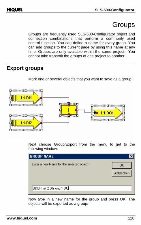
HIQUELHIQUELHIQUELHIQUEL SLS-500-Configurator
www.hiquel.com 128
Groups Groups are frequently used SLS-500-Configurator object and connection combinations that perform a commonly used control function. You can define a name for every group. You can add groups to the current page by using this name at any time. Groups are only available within the same project. You cannot take transmit the groups of one project to another!
Export groups
Mark one or several objects that you want to save as a group:
Next choose Group/Export from the menu to get to the following window:
Now type in a new name for the group and press OK. The objects will be exported as a group.

HIQUELHIQUELHIQUELHIQUEL SLS-500-Configurator
www.hiquel.com 129
Import groups
To import a previously saved group proceed as follows:
Choose Group/Import from the menu to get to the following list:
From the list choose which group you want to import and press OK. All objects of the group will be added to the current page and are available again available as single objects!
Delete groups
In order to delete a group choose Group/Delete from the menu to get to a list containing the available groups:

HIQUELHIQUELHIQUELHIQUEL SLS-500-Configurator
www.hiquel.com 130
Choose the group you want to delete and confirm by clicking OK.
Adjust controller
From the list choose which controller you want to import and press OK. All objects of the group will be added to the current page and are available again available as single objects!
!IMPORTANT!: All controllers from the list must be used on an own page. All inputs and outputs of the controller are variable.
Controller-status Defined-value
Actual value
Proportional constant
Integration constant
Upper Hysterese
Lower Hysterese
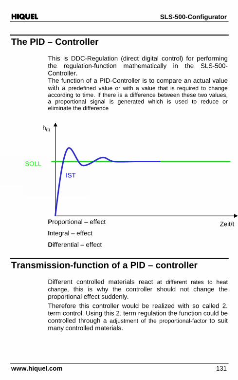
HIQUELHIQUELHIQUELHIQUEL SLS-500-Configurator
www.hiquel.com 131
The PID – Controller
This is DDC-Regulation (direct digital control) for performing the regulation-function mathematically in the SLS-500-Controller. The function of a PID-Controller is to compare an actual value with a predefined value or with a value that is required to change according to time. If there is a difference between these two values, a proportional signal is generated which is used to reduce or eliminate the difference
Proportional – effect
Integral – effect
Differential – effect
Transmission-function of a PID – controller
Different controlled materials react at different rates to heat change, this is why the controller should not change the proportional effect suddenly. Therefore this controller would be realized with so called 2. term control. Using this 2. term regulation the function could be controlled through a adjustment of the proportional-factor to suit many controlled materials.
IST
h(t)
SOLL
Zeit/t
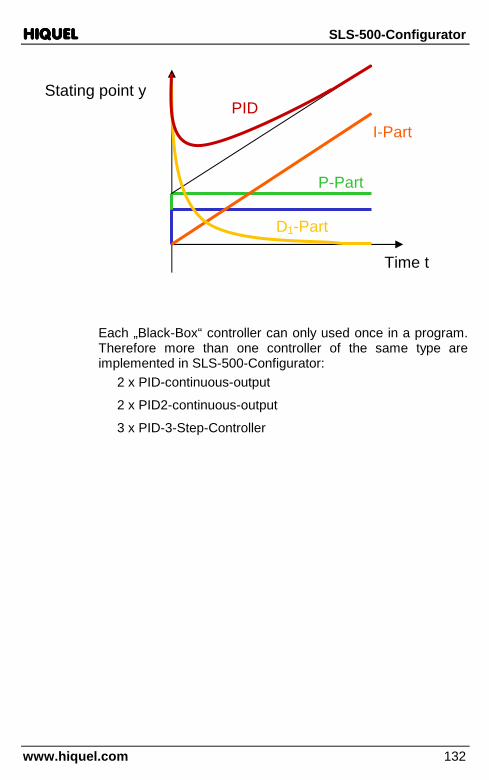
HIQUELHIQUELHIQUELHIQUEL SLS-500-Configurator
www.hiquel.com 132
Each „Black-Box“ controller can only used once in a program. Therefore more than one controller of the same type are implemented in SLS-500-Configurator: 2 x PID-continuous-output
2 x PID2-continuous-output
3 x PID-3-Step-Controller
Stating point y
P-Part
I-Part
D1-Part
PID
Time t
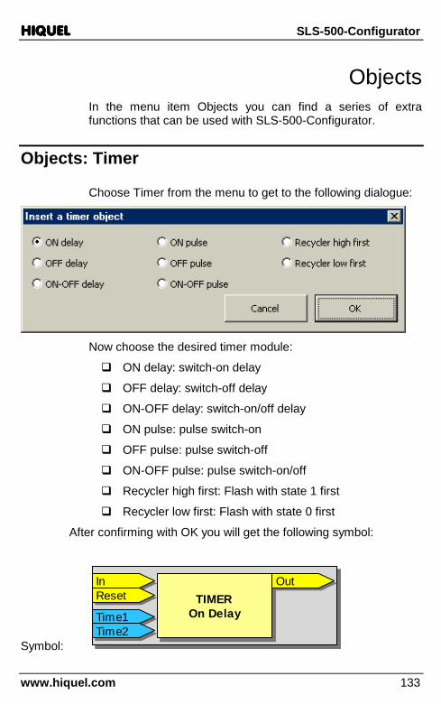
HIQUELHIQUELHIQUELHIQUEL SLS-500-Configurator
www.hiquel.com 133
Objects In the menu item Objects you can find a series of extra functions that can be used with SLS-500-Configurator.
Objects: Timer
Choose Timer from the menu to get to the following dialogue:
Now choose the desired timer module:
� ON delay: switch-on delay
� OFF delay: switch-off delay
� ON-OFF delay: switch-on/off delay
� ON pulse: pulse switch-on
� OFF pulse: pulse switch-off
� ON-OFF pulse: pulse switch-on/off
� Recycler high first: Flash with state 1 first
� Recycler low first: Flash with state 0 first
After confirming with OK you will get the following symbol:
Symbol:
TIMEROn DelayTIMER
On Delay
InIn OutOutResetReset
Time1Time1Time2Time2
TIMEROn DelayTIMER
On Delay
InIn OutOutResetReset
Time1Time1Time2Time2
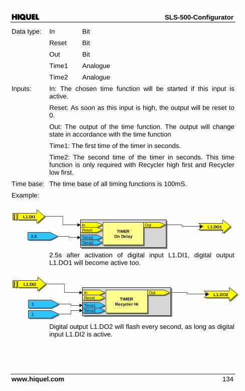
HIQUELHIQUELHIQUELHIQUEL SLS-500-Configurator
www.hiquel.com 134
Data type: In Bit
Reset Bit
Out Bit
Time1 Analogue
Time2 Analogue
Inputs: In: The chosen time function will be started if this input is active.
Reset: As soon as this input is high, the output will be reset to 0.
Out: The output of the time function. The output will change state in accordance with the time function
Time1: The first time of the timer in seconds.
Time2: The second time of the timer in seconds. This time function is only required with Recycler high first and Recycler low first.
Time base: The time base of all timing functions is 100mS.
Example:
TIMEROn DelayTIMER
On Delay
InIn OutOutResetReset
Time1Time1Time2Time2
TIMEROn DelayTIMER
On Delay
InIn OutOutResetReset
Time1Time1Time2Time2
L1.DI1L1.DI1
2.52.5
L1.DO1L1.DO1
2.5s after activation of digital input L1.DI1, digital output L1.DO1 will become active too.
L1.DI2L1.DI2
11
L1.DO2L1.DO2TIMER
Recycler HiTIMER
Recycler Hi
InIn OutOutResetReset
Time1Time1Time2Time2
TIMERRecycler Hi
TIMERRecycler Hi
InIn OutOutResetReset
Time1Time1Time2Time2
11 Digital output L1.DO2 will flash every second, as long as digital input L1.DI2 is active.

HIQUELHIQUELHIQUELHIQUEL SLS-500-Configurator
www.hiquel.com 135
Objects: Timer: ON delay
Zeit in s
In
Out
TIMER ON delay
Time1
Reset
Objects: Timer: OFF delay
Zeit in s
In
Out
TIMER OFF delay
Time1
Reset
Objects: Timer: ON OFF delay
Time1
Zeit in s
In
Out
TIMER ON OFF delay
Time2
Reset
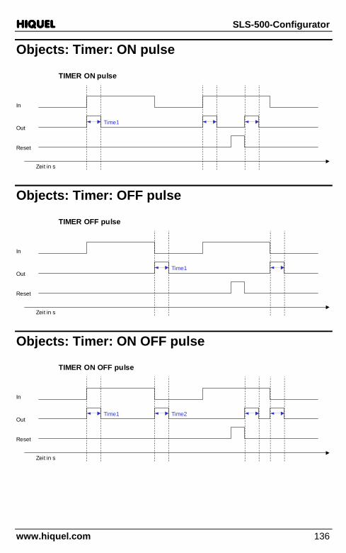
HIQUELHIQUELHIQUELHIQUEL SLS-500-Configurator
www.hiquel.com 136
Objects: Timer: ON pulse
Zeit in s
In
Out
TIMER ON pulse
Time1
Reset
Objects: Timer: OFF pulse
Zeit in s
In
Out
TIMER OFF pulse
Time1
Reset
Objects: Timer: ON OFF pulse
Zeit in s
In
Out
TIMER ON OFF pulse
Time2
Reset
Time1

HIQUELHIQUELHIQUELHIQUEL SLS-500-Configurator
www.hiquel.com 137
Objects: Timer: Recycler high first
Zeit in s
In
Out
TIMER Recycler high first
Time1
Reset
Time2
Objects: Timer: Recycler low first
Zeit in s
In
Out
TIMER Recycler low first
Time1
Reset
Time2
Objects: Timer: Delay
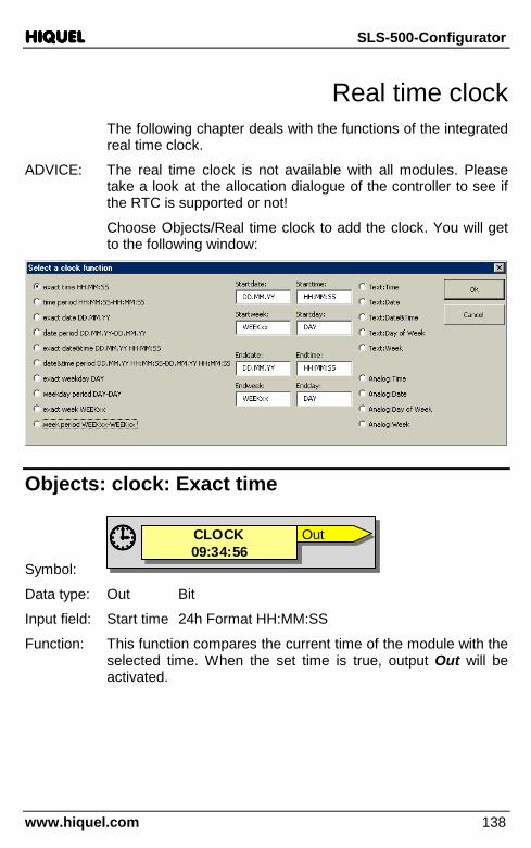
HIQUELHIQUELHIQUELHIQUEL SLS-500-Configurator
www.hiquel.com 138
Real time clock The following chapter deals with the functions of the integrated real time clock.
ADVICE: The real time clock is not available with all modules. Please take a look at the allocation dialogue of the controller to see if the RTC is supported or not!
Choose Objects/Real time clock to add the clock. You will get to the following window:
Objects: clock: Exact time
Symbol:
CLOCK09:34:56CLOCK09:34:56���� OutOutCLOCK09:34:56CLOCK09:34:56���� OutOut
Data type: Out Bit
Input field: Start time 24h Format HH:MM:SS
Function: This function compares the current time of the module with the selected time. When the set time is true, output Out will be activated.
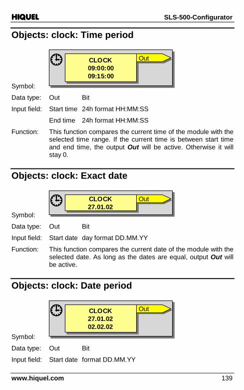
HIQUELHIQUELHIQUELHIQUEL SLS-500-Configurator
www.hiquel.com 139
Objects: clock: Time period
Symbol:
CLOCK09:00:0009:15:00
CLOCK09:00:0009:15:00
���� OutOutCLOCK09:00:0009:15:00
CLOCK09:00:0009:15:00
���� OutOut
Data type: Out Bit
Input field: Start time 24h format HH:MM:SS
End time 24h format HH:MM:SS
Function: This function compares the current time of the module with the selected time range. If the current time is between start time and end time, the output Out will be active. Otherwise it will stay 0.
Objects: clock: Exact date
Symbol:
CLOCK27.01.02CLOCK27.01.02���� OutOutCLOCK27.01.02CLOCK27.01.02���� OutOut
Data type: Out Bit
Input field: Start date day format DD.MM.YY
Function: This function compares the current date of the module with the selected date. As long as the dates are equal, output Out will be active.
Objects: clock: Date period
Symbol:
CLOCK27.01.0202.02.02
CLOCK27.01.0202.02.02
���� OutOutCLOCK27.01.0202.02.02
CLOCK27.01.0202.02.02
���� OutOut
Data type: Out Bit
Input field: Start date format DD.MM.YY

HIQUELHIQUELHIQUELHIQUEL SLS-500-Configurator
www.hiquel.com 140
End date format DD.MM.YY
Function: This function compares the current date of the module with the selected date range. As long as the current date is within the adjusted range, output Out will be active.
Objects: clock: Exact date&time
Symbol:
CLOCK15.07.02 09:00:00
CLOCK15.07.02 09:00:00���� OutOutCLOCK15.07.02 09:00:00
CLOCK15.07.02 09:00:00���� OutOut
Data type: Out Bit
Input field: Start date format DD.MM.YY
Start time 24h-format HH:MM:SS
Function: This function compares the current date and the current time of the module with the selected date and time. If both agree, output Out will be activated.
Objects: clock: Date&time period
Symbol:
CLOCK15.07.02 09:00:0016.07.02 12:00:00
CLOCK15.07.02 09:00:0016.07.02 12:00:00
���� OutOutCLOCK15.07.02 09:00:0016.07.02 12:00:00
CLOCK15.07.02 09:00:0016.07.02 12:00:00
���� OutOut
Data type: Out Bit
Input field: Start date format DD.MM.YY
Start time 24h-format HH:MM:SS
End date format DD.MM.YY
End time 24h-format HH:MM:SS
Function: This function compares the current time and the current date of the module with the selected time range. Only if the current time and date is within the specified time range, output Out will be activated.

HIQUELHIQUELHIQUELHIQUEL SLS-500-Configurator
www.hiquel.com 141
Objects: clock: Exact Weekday
Symbol:
CLOCKMON
CLOCKMON���� OutOutCLOCKMON
CLOCKMON���� OutOut
Data type: Out Bit
Input field: Start day weekday, English spelling:
MON,TUE,WED,THU,FRI,SAT,SUN
Function: This function compares the current weekday of the module with the selected weekday. If the weekdays match, output Out will be activated.
Objects: clock: Weekday period
Symbol:
CLOCKMONWED
CLOCKMONWED
���� OutOutCLOCKMONWED
CLOCKMONWED
���� OutOut
Data type: Out Bit
Input field: Start day weekday, English spelling:
MON,TUE,WED,THU,FRI,SAT,SUN
End day weekday, English spelling:
MON,TUE,WED,THU,FRI,SAT,SUN
Function: This function compares the current weekday of the module with the selected weekday range. If the current day is within the specified range, the output Out will be active.
Objects: clock: Exact Week
Symbol:
CLOCKWEEK43CLOCKWEEK43���� OutOutCLOCKWEEK43CLOCKWEEK43���� OutOut
Data type: Out Bit
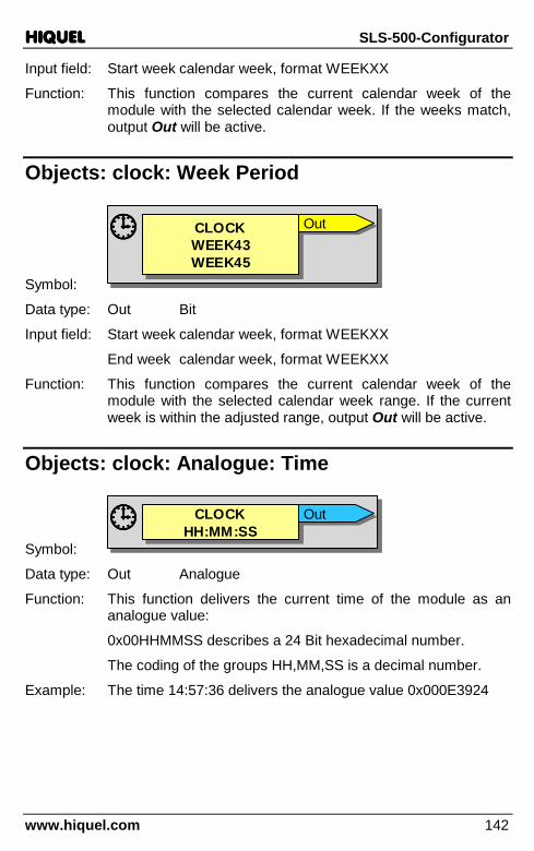
HIQUELHIQUELHIQUELHIQUEL SLS-500-Configurator
www.hiquel.com 142
Input field: Start week calendar week, format WEEKXX
Function: This function compares the current calendar week of the module with the selected calendar week. If the weeks match, output Out will be active.
Objects: clock: Week Period
Symbol:
CLOCKWEEK43WEEK45
CLOCKWEEK43WEEK45
���� OutOutCLOCKWEEK43WEEK45
CLOCKWEEK43WEEK45
���� OutOut
Data type: Out Bit
Input field: Start week calendar week, format WEEKXX
End week calendar week, format WEEKXX
Function: This function compares the current calendar week of the module with the selected calendar week range. If the current week is within the adjusted range, output Out will be active.
Objects: clock: Analogue: Time
Symbol:
CLOCKHH:MM:SSCLOCK
HH:MM:SS���� OutOutCLOCKHH:MM:SSCLOCK
HH:MM:SS���� OutOut
Data type: Out Analogue
Function: This function delivers the current time of the module as an analogue value:
0x00HHMMSS describes a 24 Bit hexadecimal number.
The coding of the groups HH,MM,SS is a decimal number.
Example: The time 14:57:36 delivers the analogue value 0x000E3924

HIQUELHIQUELHIQUELHIQUEL SLS-500-Configurator
www.hiquel.com 143
Objects: clock: Analogue: Date
Symbol:
CLOCKYY.MM.DDCLOCK
YY.MM.DD���� OutOutCLOCKYY.MM.DDCLOCK
YY.MM.DD���� OutOut
Data type: Out Analogue
Function: This function delivers the current date of the module as an analogue value:
0x00YYMMDD describes a 24 Bit hexadecimal number.
The coding of the groups YY,MM,DD is a decimal number.
Example: The date 16.05.02 delivers the analogue value 0x00020510
Objects: clock: Analogue: Day of Week
Symbol:
CLOCKDDD
CLOCKDDD���� OutOutCLOCKDDD
CLOCKDDD���� OutOut
Data type: Out Analogue
Function: This function delivers the current weekday of the module as an analogue value:
0x0000000D describes a 4 Bit hexadecimal number.
The coding of the group D is a decimal number. Monday has the value 0, Tuesday has the value 1, and so forth.
Example: Weekday Thursday (THU) delivers 0x00000003 as a result.
Objects: clock: Analogue: Week of year
Symbol:
CLOCKWEEKxxCLOCKWEEKxx���� OutOutCLOCKWEEKxxCLOCKWEEKxx���� OutOut
Data type: Out Analogue
Function: This function delivers the current calendar week of the module as an analogue value:

HIQUELHIQUELHIQUELHIQUEL SLS-500-Configurator
www.hiquel.com 144
0x000000WW describes a 8 bit hexadecimal number.
The coding of the group WW is a decimal number.
Example: Calendar week 17 delivers 0x00000011 as a result.
Objects: clock: Text: Time
Symbol:
CLOCKHH:MM:SSCLOCK
HH:MM:SS���� OutOutCLOCKHH:MM:SSCLOCK
HH:MM:SS���� OutOut
Data type: Out Text
Function: This function delivers the current time as a 8 character text with a 24h format HH:MM:SS.
Objects: clock: Text: Date
Symbol:
CLOCKDD.MM.YYCLOCK
DD.MM.YY���� OutOutCLOCKDD.MM.YYCLOCK
DD.MM.YY���� OutOut
Data type: Out Text
Function: This function delivers the current date as an 8-character text with a DD.MM.YY format.
Objects: clock: Text: Date&Time
Symbol:
CLOCKDD.MM.YY HH:MM:SS
CLOCKDD.MM.YY HH:MM:SS���� OutOutCLOCKDD.MM.YY HH:MM:SS
CLOCKDD.MM.YY HH:MM:SS���� OutOut
Data type: Out Text
Function: This function delivers the current date and the current time as a 17-character text with a DD.MM.YY HH:MM:SS format.

HIQUELHIQUELHIQUELHIQUEL SLS-500-Configurator
www.hiquel.com 145
Objects: clock: Text: Day of Week
Symbol:
CLOCKDDD
CLOCKDDD���� OutOutCLOCKDDD
CLOCKDDD���� OutOut
Data type: Out Text
Function: This function delivers the current weekday as a 3-character text. The weekdays have the English day abbreviation: MON, TUE, WED, THU, FRI, SAT, SUN.
Objects: clock: Text: Week of year
Symbol:
CLOCKWEEKxxCLOCKWEEKxx���� OutOutCLOCKWEEKxxCLOCKWEEKxx���� OutOut
Data type: Out Text
Function: This function delivers the current calendar week as a 6-character text with a WEEKXX format.

HIQUELHIQUELHIQUELHIQUEL SLS-500-Configurator
www.hiquel.com 146
CAN Objects (CANBUS) This chapter deals with the CAN functions, which are available with some devices.
To add CAN objects choose Objects/CAN bus from the menu. The following dialogue will be opened:
Objects: CAN Message In
Symbol:
CAN MESSAGECAN MESSAGE
IDID 0x12340x1234 MessageMessage
CAN MESSAGECAN MESSAGE
IDID 0x12340x1234 MessageMessage
Data type: Message Bit
Function: If CAN Bus receives the message 0x1234, output Message will be activated for one cycle.

HIQUELHIQUELHIQUELHIQUEL SLS-500-Configurator
www.hiquel.com 147
Objects: CAN Value In
Symbol:
CAN VALUECAN VALUE
IDID 0x12340x1234 MessageMessageValueValue
CAN VALUECAN VALUE
IDID 0x12340x1234 MessageMessageValueValue
Data type: Message Bit
Value Analogue
Function: If CAN Bus receives the message 0x1234, output Message will be activated for one cycle and the received analogue value will be available at output Value.
Objects: CAN Text In
Symbol:
CAN TEXTCAN TEXT
IDID 0x12340x1234 MessageMessageTextText
CAN TEXTCAN TEXT
IDID 0x12340x1234 MessageMessageTextText
Data type: Message Bit
Text Text
Function: If CAN Bus receives the message 0x1234, output Message will be activated for one cycle and the received text value will be available at output Text.
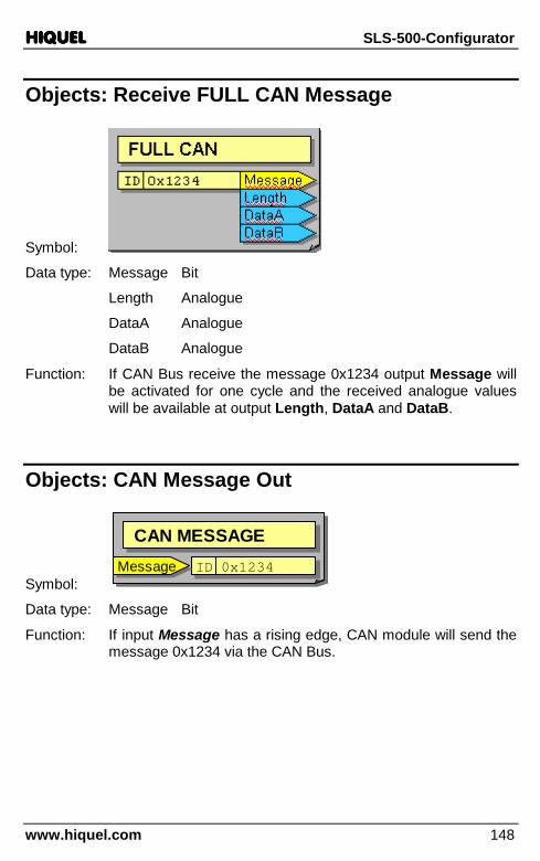
HIQUELHIQUELHIQUELHIQUEL SLS-500-Configurator
www.hiquel.com 148
Objects: Receive FULL CAN Message
Symbol:
Data type: Message Bit
Length Analogue
DataA Analogue
DataB Analogue
Function: If CAN Bus receive the message 0x1234 output Message will be activated for one cycle and the received analogue values will be available at output Length, DataA and DataB.
Objects: CAN Message Out
Symbol:
CAN MESSAGECAN MESSAGE
IDID 0x12340x1234MessageMessage
CAN MESSAGECAN MESSAGE
IDID 0x12340x1234MessageMessage
Data type: Message Bit
Function: If input Message has a rising edge, CAN module will send the message 0x1234 via the CAN Bus.

HIQUELHIQUELHIQUELHIQUEL SLS-500-Configurator
www.hiquel.com 149
Objects: CAN Value Out
Symbol:
CAN VALUECAN VALUE
IDID 0x12340x1234MessageMessageValueValue
CAN VALUECAN VALUE
IDID 0x12340x1234MessageMessageValueValue
Data type: Message Bit
Value Analogue
Function: If input Message has a rising edge, CAN module will send the message 0x1234 via the CAN Bus. The analogue value will be sent simultaneously via the data range CAN Frames.
Objects: CAN Text Out
Symbol:
CAN TEXTCAN TEXT
IDID 0x12340x1234MessageMessageTextText
CAN TEXTCAN TEXT
IDID 0x12340x1234MessageMessageTextText
Data type: Message Bit
Text Text
Function: If input Message has a rising edge, CAN module will send the message 0x1234 via the CAN Bus. The text value will be sent simultaneously via the data range CAN Frames.
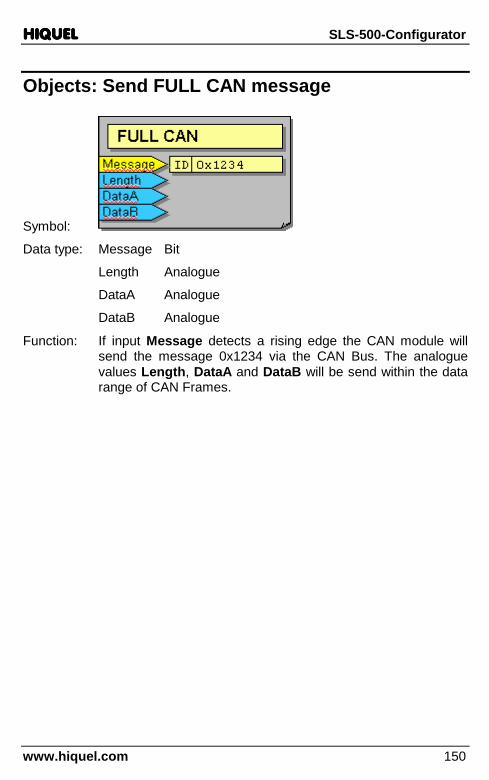
HIQUELHIQUELHIQUELHIQUEL SLS-500-Configurator
www.hiquel.com 150
Objects: Send FULL CAN message
Symbol:
Data type: Message Bit
Length Analogue
DataA Analogue
DataB Analogue
Function: If input Message detects a rising edge the CAN module will send the message 0x1234 via the CAN Bus. The analogue values Length, DataA and DataB will be send within the data range of CAN Frames.

HIQUELHIQUELHIQUELHIQUEL SLS-500-Configurator
www.hiquel.com 151
SIO functions (Serial input/output) Some modules have a free serial port. You can address them with the following functions. Choose Objects/Serial device from the menu to get to the following window:
Objects: SIO: Send Text
Symbol:
SIO1Send Text
SIO1Send Text
SendSend FinishedFinishedTextText
SIO1Send Text
SIO1Send Text
SendSend FinishedFinishedTextText
Data type: Send Bit
Text Text
Finished Bit
Function: If a rising edge is detected at input Send, this function will send the text string of input Text. When the transfer is finished, output Finished will be active.
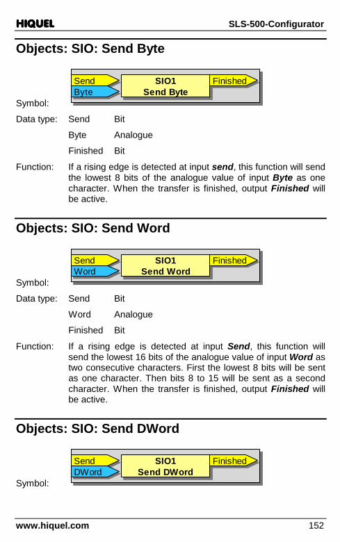
HIQUELHIQUELHIQUELHIQUEL SLS-500-Configurator
www.hiquel.com 152
Objects: SIO: Send Byte
Symbol:
SIO1Send Byte
SIO1Send Byte
SendSend FinishedFinishedByteByte
SIO1Send Byte
SIO1Send Byte
SendSend FinishedFinishedByteByte
Data type: Send Bit
Byte Analogue
Finished Bit
Function: If a rising edge is detected at input send, this function will send the lowest 8 bits of the analogue value of input Byte as one character. When the transfer is finished, output Finished will be active.
Objects: SIO: Send Word
Symbol:
SIO1Send Word
SIO1Send Word
SendSend FinishedFinishedWordWord
SIO1Send Word
SIO1Send Word
SendSend FinishedFinishedWordWord
Data type: Send Bit
Word Analogue
Finished Bit
Function: If a rising edge is detected at input Send, this function will send the lowest 16 bits of the analogue value of input Word as two consecutive characters. First the lowest 8 bits will be sent as one character. Then bits 8 to 15 will be sent as a second character. When the transfer is finished, output Finished will be active.
Objects: SIO: Send DWord
Symbol:
SIO1Send DWord
SIO1Send DWord
SendSend FinishedFinishedDWordDWord
SIO1Send DWord
SIO1Send DWord
SendSend FinishedFinishedDWordDWord

HIQUELHIQUELHIQUELHIQUEL SLS-500-Configurator
www.hiquel.com 153
Data type: Send Bit
DWord Analogue
Finished Bit
Function: If a rising edge is detected at input Send, this function will send all 32 bits of the analogue value of input Word as four consecutive characters. First the lowest 8 bits will be sent as one character. Then bits 8 to 15 will be sent as a second. After that bits 16 to 24 will follow up as a third. Finally the last 8 bits will be sent as a fourth character. When the transfer is finished, output Finished will be active.
Objects: SIO: Receive Byte
Symbol:
SIO1Receive Byte
SIO1Receive Byte
ValueValueSIO1Receive Byte
SIO1Receive Byte
ValueValue
Data type: Value Analogue
Function: This function detects whether a character has been received at the serial port. If so, Value returns the lowest 8 code bits of the received character. If no character is received the analogue value 9999.000 will be returned.
Objects: SIO: Receive Text
Symbol:
SIO1Receive Text
SIO1Receive Text
ValueValueSIO1Receive Text
SIO1Receive Text
ValueValue
Data type: Value Text
Function: This function detects whether a character has been received at the serial port. If so, a 1-character text message containing the received character will be returned in the output Value. If no text is received, a blank text will be returned.
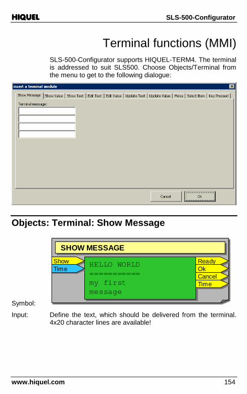
HIQUELHIQUELHIQUELHIQUEL SLS-500-Configurator
www.hiquel.com 154
Terminal functions (MMI) SLS-500-Configurator supports HIQUEL-TERM4. The terminal is addressed to suit SLS500. Choose Objects/Terminal from the menu to get to the following dialogue:
Objects: Terminal: Show Message
Symbol:
ShowShow
SHOW MESSAGESHOW MESSAGE
HELLO WORLD===========my firstmessage
HELLO WORLD===========my firstmessage
TimeTimeReadyReadyOkOkCancelCancelTimeTime
ShowShow
SHOW MESSAGESHOW MESSAGE
HELLO WORLD===========my firstmessage
HELLO WORLD===========my firstmessage
TimeTimeReadyReadyOkOkCancelCancelTimeTime
Input: Define the text, which should be delivered from the terminal. 4x20 character lines are available!
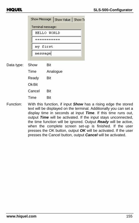
HIQUELHIQUELHIQUELHIQUEL SLS-500-Configurator
www.hiquel.com 155
Data type: Show Bit
Time Analogue
Ready Bit
Ok Bit
Cancel Bit
Time Bit
Function: With this function, if input Show has a rising edge the stored text will be displayed on the terminal. Additionally you can set a display time in seconds at input Time. If this time runs out, output Time will be activated. If the input stays unconnected, the time function will be ignored. Output Ready will be active, when the complete screen set-up is finished. If the user presses the OK button, output OK will be activated. If the user presses the Cancel button, output Cancel will be activated.
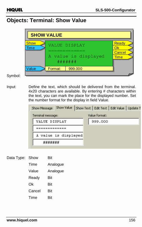
HIQUELHIQUELHIQUELHIQUEL SLS-500-Configurator
www.hiquel.com 156
Objects: Terminal: Show Value
Symbol:
ShowShow
SHOW VALUESHOW VALUE
VALUE DISPLAY=============A value is displayed
#######
VALUE DISPLAY=============A value is displayed
#######
ReadyReadyOkOkCancelCancelTimeTime
TimeTime
ValueValue Format:Format: 999.000999.000
ShowShow
SHOW VALUESHOW VALUE
VALUE DISPLAY=============A value is displayed
#######
VALUE DISPLAY=============A value is displayed
#######
ReadyReadyOkOkCancelCancelTimeTime
TimeTime
ValueValue Format:Format: 999.000999.000
Input: Define the text, which should be delivered from the terminal. 4x20 characters are available. By entering # characters within the text, you can mark the place for the displayed number. Set the number format for the display in field Value.
Data Type: Show Bit
Time Analogue
Value Analogue
Ready Bit
Ok Bit
Cancel Bit
Time Bit

HIQUELHIQUELHIQUELHIQUEL SLS-500-Configurator
www.hiquel.com 157
Function: With this function, if input Show has a rising edge the stored text will be displayed on the terminal. Additionally you can set a display time in seconds at input Time. If this time runs out, output Time will be activated. If the input stays unconnected, the time function will be ignored. Output Ready will be active when the complete screen set-up is finished. If the user presses the OK button, output OK will be activated. If the user presses the Cancel button, output Cancel will be activated. Input Value has the value which is displayed instead of the # characters.
Objects: Terminal: Show Text
Symbol:
ShowShow
SHOW TEXTSHOW TEXT
SHOW TEXT=========This is a text########
SHOW TEXT=========This is a text########
ReadyReadyOkOkCancelCancelTimeTime
TimeTimeTextText
ShowShow
SHOW TEXTSHOW TEXT
SHOW TEXT=========This is a text########
SHOW TEXT=========This is a text########
ReadyReadyOkOkCancelCancelTimeTime
TimeTimeTextText
Input: Define the text, which should be delivered from the terminal. 4x20 characters are available. By entering # characters within the text you can mark the place for the display of the text.
.
Data type: Show Bit
Time Analogue

HIQUELHIQUELHIQUELHIQUEL SLS-500-Configurator
www.hiquel.com 158
Text Text
Ready Bit
Ok Bit
Cancel Bit
Time Bit
Function: With this function, if input Show has a rising edge the stored text will be displayed at the terminal. Additionally you can set a display time in seconds at input Time. If this time runs out, output Time will be activated. If the input stays unconnected, the time function will be ignored. Output Ready will be active when the complete screen set-up is finished. If the user presses the OK button, output OK will be activated. If the user presses the Cancel button, output Cancel will be activated. Input Value receives the character string which is displayed instead of the # characters.
Objects: Terminal: Edit Text
Symbol:
EditEdit
EDIT TEXTEDIT TEXT
TimeTime EDIT TEXT=========Edit here:
#######
EDIT TEXT=========Edit here:
#######
ReadyReadyOkOkCancelCancelTimeTime
DefaultDefault
TextText
EditEdit
EDIT TEXTEDIT TEXT
TimeTime EDIT TEXT=========Edit here:
#######
EDIT TEXT=========Edit here:
#######
ReadyReadyOkOkCancelCancelTimeTime
DefaultDefault
TextText
Input: Define the text, which should be delivered from the terminal. 4x20 characters are available. By entering # characters within the text, you can mark the place for the text input.

HIQUELHIQUELHIQUELHIQUEL SLS-500-Configurator
www.hiquel.com 159
Data type: Show Bit
Time Analogue
Default Text
Text Text
Ready Bit
Ok Bit
Cancel Bit
Time Bit
Function: With this function, if input Show has a rising edge the stored text will be displayed at the terminal. Additionally you can set a display time in seconds at input Time. If this time runs out, output Time will be activated. If the input stays unconnected, the time function will be ignored. Output Ready will be active when the complete screen set-up is finished. If the user presses the OK button, output OK will be activated. If the user presses the Cancel button, output Cancel will be activated.
Input Default defines the character string that is displayed at start up of the input. This string can by edited by the user at start up too. If the user presses OK, output Text will receive the newly defined text. If the user presses Cancel the current input will be cancelled and the text Default will be delivered to output Text.

HIQUELHIQUELHIQUELHIQUEL SLS-500-Configurator
www.hiquel.com 160
Objects: Terminal: Edit Value
Symbol:
EditEdit
EDIT VALUEEDIT VALUE
EDIT VALUE==========Input a value:
#######
EDIT VALUE==========Input a value:
#######
ReadyReady
DefaultDefault Format:Format: 999.000999.000
OkOkCancelCancel
Min:Min: 0.00.0Max:Max: 100.0100.0
ValueValue
TimeTime
TimeTimeEditEdit
EDIT VALUEEDIT VALUE
EDIT VALUE==========Input a value:
#######
EDIT VALUE==========Input a value:
#######
ReadyReady
DefaultDefault Format:Format: 999.000999.000
OkOkCancelCancel
Min:Min: 0.00.0Max:Max: 100.0100.0
ValueValue
TimeTime
TimeTime
Input: Define the text, which should be delivered from the terminal. 4x20 characters are available. By entering # characters within the text, you can mark the place for the number input. Set the format for the display of the value in the field Value format. The two fields ‘Value minimum’ and ‘Value maximum’ define a number range for a valid input.
Data type: Show Bit
Time Analogue
Default Analogue
Value Analogue
Ready Bit

HIQUELHIQUELHIQUELHIQUEL SLS-500-Configurator
www.hiquel.com 161
Ok Bit
Cancel Bit
Time Bit
Function: With this function, if input Show has a rising edge the stored text will be displayed at the terminal. Additionally you can set a display time in seconds at input Time. If this time runs out, output Time will be activated. If the input stays unconnected, the time function will be ignored. Output Ready will be active when the complete screen set-up is finished. If the user presses the OK button, output OK will be activated. If the user presses the Cancel button, output Cancel will be activated.
Input Default defines the number value that is displayed at start up of the number input. If the user presses OK after entering the number, the input will be converted and the analogue value will be checked for the two limits ‘Value minimum’ and ‘Value maximum’. If the input value is within the range, output OK will be activated and the value will be delivered to output Value. If the input value is outside the range, the input cannot be continued with OK. By pressing CANCEL the value Default will be transmitted as a result of the input.
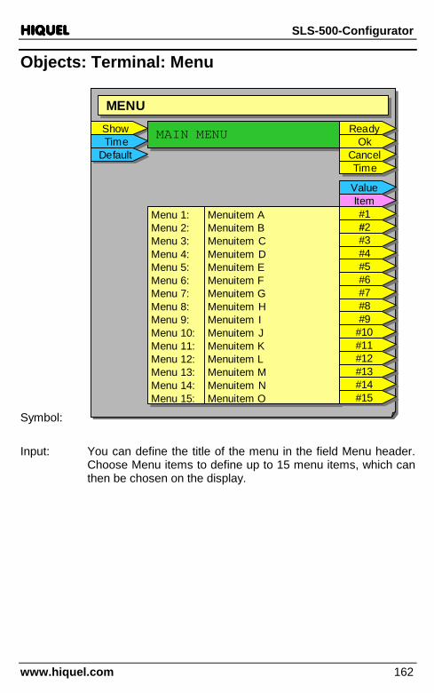
HIQUELHIQUELHIQUELHIQUEL SLS-500-Configurator
www.hiquel.com 162
Objects: Terminal: Menu
Symbol:
ShowShow
MENUMENU
MAIN MENUMAIN MENU
Menu 1:Menu 2:Menu 3:Menu 4:Menu 5:Menu 6:Menu 7:Menu 8:Menu 9:Menu 10:Menu 11:Menu 12:Menu 13:Menu 14:Menu 15:
Menu 1:Menu 2:Menu 3:Menu 4:Menu 5:Menu 6:Menu 7:Menu 8:Menu 9:Menu 10:Menu 11:Menu 12:Menu 13:Menu 14:Menu 15:
Menuitem AMenuitem BMenuitem CMenuitem DMenuitem EMenuitem FMenuitem GMenuitem HMenuitem IMenuitem JMenuitem KMenuitem LMenuitem MMenuitem NMenuitem O
Menuitem AMenuitem BMenuitem CMenuitem DMenuitem EMenuitem FMenuitem GMenuitem HMenuitem IMenuitem JMenuitem KMenuitem LMenuitem MMenuitem NMenuitem O
TimeTimeDefaultDefault
ValueValue
ReadyReadyOkOk
CancelCancelTimeTime
ItemItem#1#1#2#2#3#3#4#4#5#5#6#6#7#7#8#8#9#9
#10#10#11#11#12#12#13#13#14#14#15#15
Input: You can define the title of the menu in the field Menu header. Choose Menu items to define up to 15 menu items, which can then be chosen on the display.

HIQUELHIQUELHIQUELHIQUEL SLS-500-Configurator
www.hiquel.com 163
Data type: Show Bit
Time Analogue
Default Analogue
Value Analogue
Item Text
Ready Bit
Ok Bit
Cancel Bit
Time Bit
#1-#15 Bit
Function: With this function, if input Show has a rising edge the stored text will be displayed at the terminal. Additionally you can set a display time in seconds at input Time. If this time runs out, output Time will be activated. If the input stays unconnected, the time function will be ignored. Output Ready will be active, if the complete screen set-up is finished. If the user presses the OK button, output OK will be activated. If the user presses the Cancel button, output Cancel will be activated.
A menu will be build up. The selected entry corresponds to the input Default. If this entry is unconnected, the first menu entry will always be selected. If you choose a menu entry and press OK, the number of the chosen menu entry will be delivered to

HIQUELHIQUELHIQUELHIQUEL SLS-500-Configurator
www.hiquel.com 164
output Value. The menu entry text will be delivered to output Item and the corresponding output #1 to #15 will be activated too. If you press CANCEL only output Cancel will be activated.
Objects: Terminal: Select item
Symbol:
ShowShow
SELECT ITEMSELECT ITEM
SELECT ITEM===========Item:###############Choose one
SELECT ITEM===========Item:###############Choose one
Menu 1:Menu 2:Menu 3:Menu 4:Menu 5:Menu 6:Menu 7:Menu 8:Menu 9:Menu 10:Menu 11:Menu 12:Menu 13:Menu 14:Menu 15:
Menu 1:Menu 2:Menu 3:Menu 4:Menu 5:Menu 6:Menu 7:Menu 8:Menu 9:Menu 10:Menu 11:Menu 12:Menu 13:Menu 14:Menu 15:
Item AItem BItem CItem DItem EItem FItem GItem HItem IItem JItem KItem LItem MItem NItem O
Item AItem BItem CItem DItem EItem FItem GItem HItem IItem JItem KItem LItem MItem NItem O
TimeTimeDefaultDefault
ValueValue
ReadyReadyOkOk
CancelCancelTimeTime
ItemItem#1#1#2#2#3#3#4#4#5#5#6#6#7#7#8#8#9#9
#10#10#11#11#12#12#13#13#14#14#15#15
Input: Enter the text for the display in field Terminal message. The position for the text entries has to be marked by #-characters. Choose Items to select to define up to 15 entries, which can then be chosen on the display.

HIQUELHIQUELHIQUELHIQUEL SLS-500-Configurator
www.hiquel.com 165
Data type: Show Bit
Time Analogue
Default Analogue
Value Analogue
Item Text
Ready Bit
Ok Bit
Cancel Bit
Time Bit
#1-#15 Bit
Function: with this function, if input Show has a rising edge the terminal will display the stored text. Additionally you can set a display time in seconds at input Time. If this time runs out, output Time will be activated. If the input stays unconnected, the time function will be ignored. Output Ready will be active when the complete screen set-up is finished. If the user presses the OK button, output OK will be activated. If the user presses the Cancel button, output Cancel will be activated.
The entered message will be build up. The displayed entry corresponds to input Default. If this input is unconnected, the first entry will always be displayed. If you choose an entry and press OK, output Value will output the number of the chosen entry. Output Item will output the entry text and the

HIQUELHIQUELHIQUELHIQUEL SLS-500-Configurator
www.hiquel.com 166
corresponding output #1 to #15 will be activated too. If you press CANCEL just output Cancel would be activated.
Objects: Terminal: Update Value
Symbol:
UpdateUpdate
UPDATE VALUEUPDATE VALUE
ValueValueXXYY
Format:Format: 9999.0009999.000ReadyReadyUpdateUpdate
UPDATE VALUEUPDATE VALUE
ValueValueXXYY
Format:Format: 9999.0009999.000ReadyReady
Input: Enter the format for the analogue number into the field Value.
Data type: Update Bit
Value Analogue
X Analogue
Y Analogue
Ready Bit
Function: The current value of input Value will be formatted with the specified format and will be displayed from position X and Y in the terminal content. The coordinates will be counted beginning with (0,0). This action will be executed with every rising edge at input Update. Output Ready will be activated immediately after the display of the number.
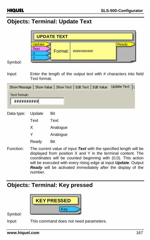
HIQUELHIQUELHIQUELHIQUEL SLS-500-Configurator
www.hiquel.com 167
Objects: Terminal: Update Text
Symbol:
UpdateUpdate
UPDATE TEXTUPDATE TEXT
TextTextXXYY
Format:Format: ####################ReadyReadyUpdateUpdate
UPDATE TEXTUPDATE TEXT
TextTextXXYY
Format:Format: ####################ReadyReady
Input: Enter the length of the output text with # characters into field Text format.
Data type: Update Bit
Text Text
X Analogue
Y Analogue
Ready Bit
Function: The current value of input Text with the specified length will be displayed from position X and Y in the terminal content. The coordinates will be counted beginning with (0,0). This action will be executed with every rising edge at input Update. Output Ready will be activated immediately after the display of the number.
Objects: Terminal: Key pressed
Symbol:
KEY PRESSEDKEY PRESSED
KeyKey
KEY PRESSEDKEY PRESSED
KeyKey
Input: This command does not need parameters.

HIQUELHIQUELHIQUELHIQUEL SLS-500-Configurator
www.hiquel.com 168
Data type: Key Analogue
Function: The current value of the keys will be delivered from output Key. If no key is pressed, the value 0 will be returned. Otherwise the following code will be returned (Total number between 1 and 9):
2.000
5.000
9.000
3.000
7.000
4.000
8.000
6.000
1.000

HIQUELHIQUELHIQUELHIQUEL SLS-500-Configurator
www.hiquel.com 169
Memory Card This chapter deals with all functions, which enable the saving of values to remnant memories like Memory Card.
Choose Objects/Memory Card from the menu to get to the following window:
Objects: MemoryCard: Read Value into SLS500 memory
Symbol:
Read ����Read ����
IndexIndex
MEMORY CARDMEMORY CARD
My VarMy VarRead ����Read ����
IndexIndex
MEMORY CARDMEMORY CARD
My VarMy Var
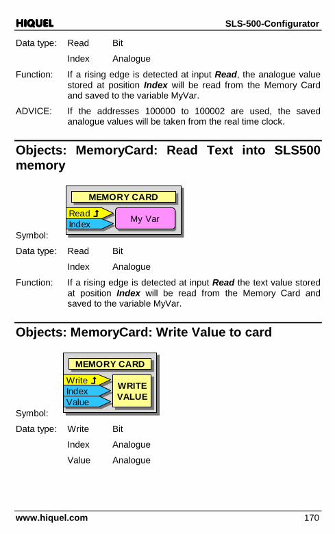
HIQUELHIQUELHIQUELHIQUEL SLS-500-Configurator
www.hiquel.com 170
Data type: Read Bit
Index Analogue
Function: If a rising edge is detected at input Read, the analogue value stored at position Index will be read from the Memory Card and saved to the variable MyVar.
ADVICE: If the addresses 100000 to 100002 are used, the saved analogue values will be taken from the real time clock.
Objects: MemoryCard: Read Text into SLS500 memory
Symbol:
Read ����Read ����
IndexIndex
MEMORY CARDMEMORY CARD
My VarMy VarRead ����Read ����
IndexIndex
MEMORY CARDMEMORY CARD
My VarMy Var
Data type: Read Bit
Index Analogue
Function: If a rising edge is detected at input Read the text value stored at position Index will be read from the Memory Card and saved to the variable MyVar.
Objects: MemoryCard: Write Value to card
Symbol:
Write ����Write ����
IndexIndex
MEMORY CARDMEMORY CARD
ValueValueWRITEVALUEWRITEVALUE
Write ����Write ����
IndexIndex
MEMORY CARDMEMORY CARD
ValueValueWRITEVALUEWRITEVALUE
Data type: Write Bit
Index Analogue
Value Analogue

HIQUELHIQUELHIQUELHIQUEL SLS-500-Configurator
www.hiquel.com 171
Function: If a rising edge is detected at input Write, the analogue value of input Value will be saved to the Memory Card to position Index.
ADVICE: If the addresses 100000 to 100002 are used, the analogue values will be saved to the real time clock.
Objects: MemoryCard: Write Text to card
Symbol:
Write ����Write ����
IndexIndex
MEMORY CARDMEMORY CARD
TextTextWRITETEXT
WRITETEXT
Write ����Write ����
IndexIndex
MEMORY CARDMEMORY CARD
TextTextWRITETEXT
WRITETEXT
Data type: Write Bit
Index Analogue
Text Text
Function: If a rising edge is detected at input Write, the value of input Text will be saved to the Memory Card to position Index.
Objects: MemoryCard: Read Value from card
Symbol:
IndexIndexMEMORY CARDMEMORY CARD
READVALUEREADVALUE
OutOutIndexIndexMEMORY CARDMEMORY CARD
READVALUEREADVALUE
OutOut
Data type: Index Analogue
Out Analogue
Function: The current value of analogue input Index will be saved to analogue output Out as a analogue variable.
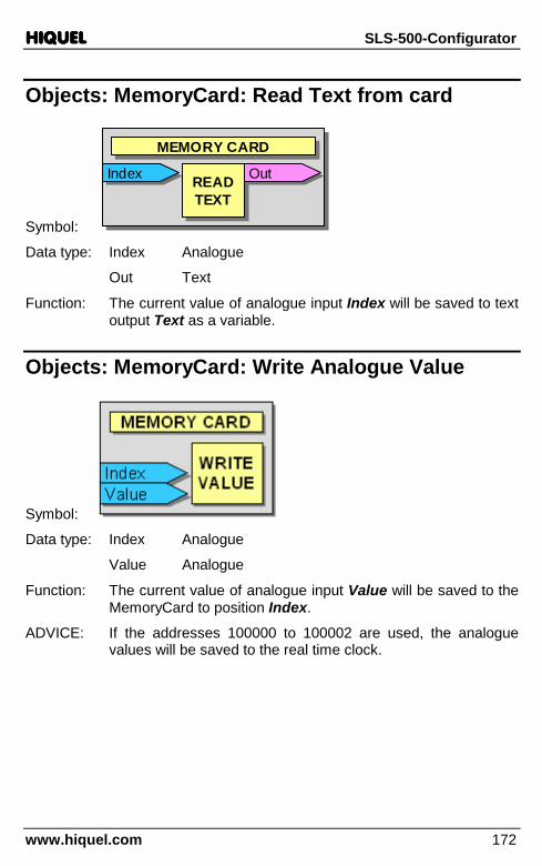
HIQUELHIQUELHIQUELHIQUEL SLS-500-Configurator
www.hiquel.com 172
Objects: MemoryCard: Read Text from card
Symbol:
IndexIndexMEMORY CARDMEMORY CARD
READTEXT
READTEXT
OutOutIndexIndexMEMORY CARDMEMORY CARD
READTEXT
READTEXT
OutOut
Data type: Index Analogue
Out Text
Function: The current value of analogue input Index will be saved to text output Text as a variable.
Objects: MemoryCard: Write Analogue Value
Symbol:
Data type: Index Analogue
Value Analogue
Function: The current value of analogue input Value will be saved to the MemoryCard to position Index.
ADVICE: If the addresses 100000 to 100002 are used, the analogue values will be saved to the real time clock.
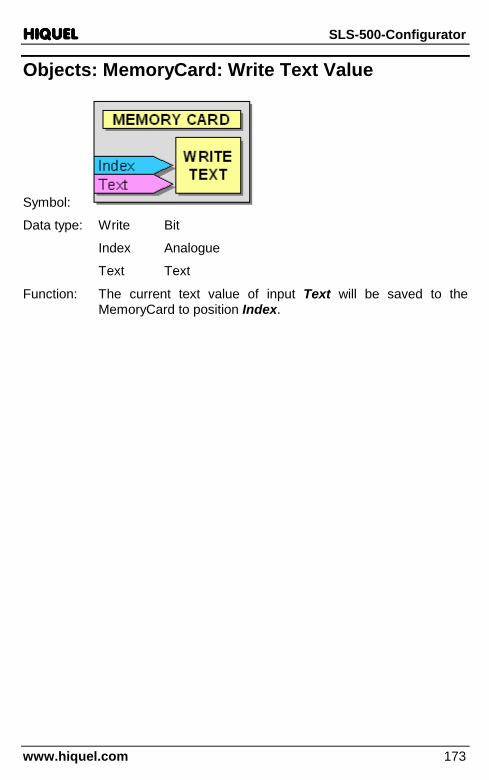
HIQUELHIQUELHIQUELHIQUEL SLS-500-Configurator
www.hiquel.com 173
Objects: MemoryCard: Write Text Value
Symbol:
Data type: Write Bit
Index Analogue
Text Text
Function: The current text value of input Text will be saved to the MemoryCard to position Index.

HIQUELHIQUELHIQUELHIQUEL SLS-500-Configurator
www.hiquel.com 174
SMS The following chapter deals with all functions which allow sending and receiving of messages via GSM modem.
Choose Objects/SMS from the menu. The following dialog will appear:
Objects: SMS: Start new short message
Symbol:
Data type: Start Bit
Ready Bit
Function: If input Start reads a rising edge a control character will be sent to the GSM modem to start the transmitting. If the transmission process is completed, output Ready will be active.

HIQUELHIQUELHIQUELHIQUEL SLS-500-Configurator
www.hiquel.com 175
Objects: SMS: Add Text to short message
Symbol:
Data type: Add Bit
Text Text
Ready Bit
Function: If input Add reads a rising edge, the current text value at input Text will be add to the message. If the process is completed, output Ready will be active.
ADVICE: A max. of 20 characters can be add to a message at once. The max. size of a message is 60 characters.
Objects: SMS: Send short message via GSM
Symbol:
Data type: Send Bit
Phone Text
Ready Bit
Error Bit
Function: If input Send reads a rising edge, the previously assembled message will be sent to the phone number stored as text value at input Phone. If the transmission process is completed, output Ready will be active. If the transmission to the GSM modem failed, output Error would be active.
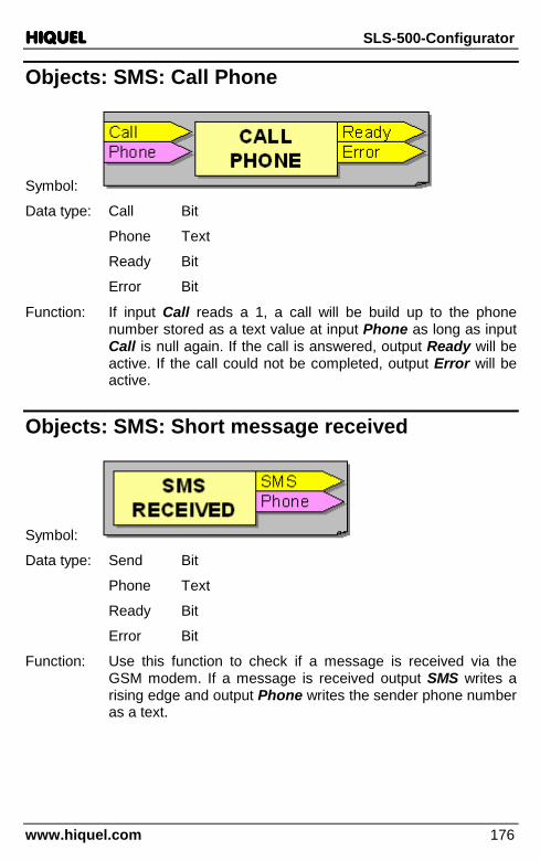
HIQUELHIQUELHIQUELHIQUEL SLS-500-Configurator
www.hiquel.com 176
Objects: SMS: Call Phone
Symbol:
Data type: Call Bit
Phone Text
Ready Bit
Error Bit
Function: If input Call reads a 1, a call will be build up to the phone number stored as a text value at input Phone as long as input Call is null again. If the call is answered, output Ready will be active. If the call could not be completed, output Error will be active.
Objects: SMS: Short message received
Symbol:
Data type: Send Bit
Phone Text
Ready Bit
Error Bit
Function: Use this function to check if a message is received via the GSM modem. If a message is received output SMS writes a rising edge and output Phone writes the sender phone number as a text.

HIQUELHIQUELHIQUELHIQUEL SLS-500-Configurator
www.hiquel.com 177
Objects: SMS: Check short message Text
Symbol:
Data type: Check Bit
Start Analogue
Text Text
OK Bit
Error Bit
Index Analogue
Function: If input Check reads a rising edge, the received text starting from Start index Start will be compared to the text value at input Text. Start counts starting with 0. If the text matches, output OK will be active. If the texts do not correspond, output Error will be active. Output Index puts out the analogue value of the compared characters.
Objects: SMS: Skip short message blanks
Symbol:
Data type: Skip Bit
Start Analogue
OK Bit
Error Bit
Index Analogue

HIQUELHIQUELHIQUELHIQUEL SLS-500-Configurator
www.hiquel.com 178
Function: If input Skip reads a rising edge, the text of the received message starting with Start index Start will be checked for blanks. Start counts starting with 0. After the text is checked, output OK will be active. If the check fails, output Error will be active. Output Index puts out the analogue value of the detected blank characters.
Objects: SMS: Get short message Analogue Value
Symbol:
Data type: Get Bit
Start Analogue
Length Analogue
OK Bit
Error Bit
Index Analogue
Value Analogue
Function: If input Get reads a rising edge, the text of the received message starting with Start index Start will be read by using the length at analogue input Length as analogue value. Start counts starting with 0. If the analogue value is put out at output Value, output OK will be active. If the output of the analogue value fails, output Error will be active. Output Index puts out the analogue value of the detected characters.

HIQUELHIQUELHIQUELHIQUEL SLS-500-Configurator
www.hiquel.com 179
Objects: SMS: Get short message Text
Symbol:
Data type: Get Bit
Start Analogue
Length Analogue
OK Bit
Error Bit
Index Analogue
Text Text
Function: If input Get reads a rising edge, the text of the received message starting with Start index Start will be read by using the length at analogue input Length as text value. Start counts starting with 0. If the text value is put out at output Text, output OK will be active. If the output of the text value fails, output Error will be active. Output Index puts out the analogue value of the detected characters.
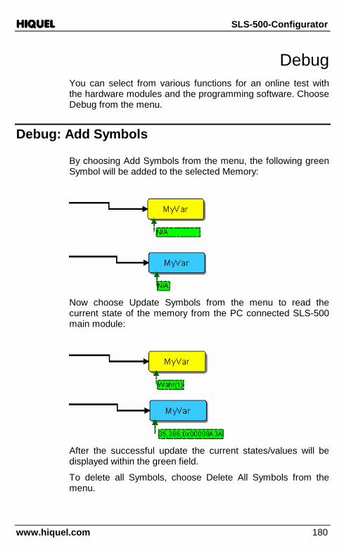
HIQUELHIQUELHIQUELHIQUEL SLS-500-Configurator
www.hiquel.com 180
Debug You can select from various functions for an online test with the hardware modules and the programming software. Choose Debug from the menu.
Debug: Add Symbols
By choosing Add Symbols from the menu, the following green Symbol will be added to the selected Memory:
Now choose Update Symbols from the menu to read the current state of the memory from the PC connected SLS-500 main module:
After the successful update the current states/values will be displayed within the green field.
To delete all Symbols, choose Delete All Symbols from the menu.
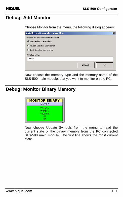
HIQUELHIQUELHIQUELHIQUEL SLS-500-Configurator
www.hiquel.com 181
Debug: Add Monitor
Choose Monitor from the menu, the following dialog appears:
Now choose the memory type and the memory name of the SLS-500 main module, that you want to monitor on the PC.
Debug: Monitor Binary Memory
Now choose Update Symbols from the menu to read the current state of the binary memory from the PC connected SLS-500 main module. The first line shows the most current state.

HIQUELHIQUELHIQUELHIQUEL SLS-500-Configurator
www.hiquel.com 182
Debug: Monitor Analogue Memory
Now choose Update Symbols from the menu to read the current state of the analogue memory from the PC connected SLS-500 main module. The first line shows the most current state.
Debug: Monitor Text Memory
Now choose Update Symbols from the menu to read the current state of the text memory from the PC connected SLS-500 main module. The first line shows the most current state.
Debug: Set Breakpoint
Choose Set Breakpoint from the menu to add a Breakpoint to the selected symbol. The program will now run only up to the Breakpoint.
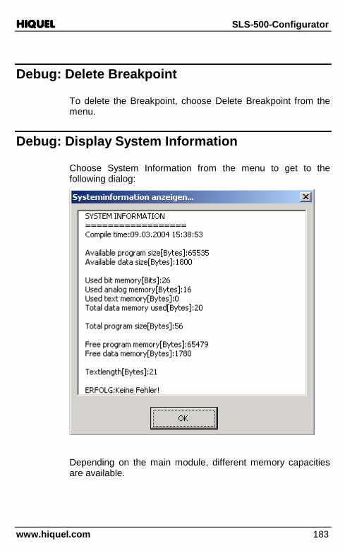
HIQUELHIQUELHIQUELHIQUEL SLS-500-Configurator
www.hiquel.com 183
Debug: Delete Breakpoint
To delete the Breakpoint, choose Delete Breakpoint from the menu.
Debug: Display System Information
Choose System Information from the menu to get to the following dialog:
Depending on the main module, different memory capacities are available.
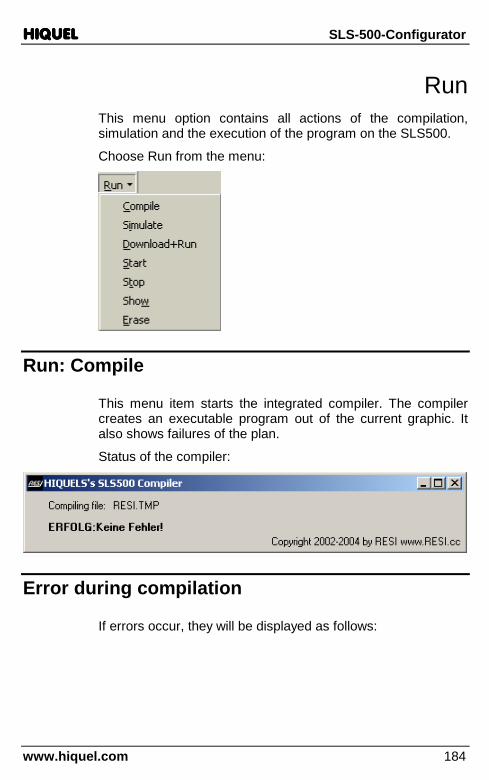
HIQUELHIQUELHIQUELHIQUEL SLS-500-Configurator
www.hiquel.com 184
Run This menu option contains all actions of the compilation, simulation and the execution of the program on the SLS500.
Choose Run from the menu:
Run: Compile
This menu item starts the integrated compiler. The compiler creates an executable program out of the current graphic. It also shows failures of the plan.
Status of the compiler:
Error during compilation
If errors occur, they will be displayed as follows:
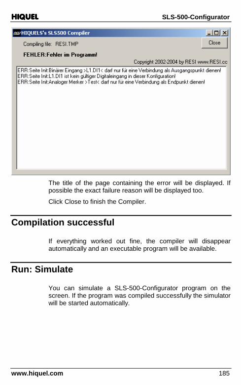
HIQUELHIQUELHIQUELHIQUEL SLS-500-Configurator
www.hiquel.com 185
The title of the page containing the error will be displayed. If possible the exact failure reason will be displayed too.
Click Close to finish the Compiler.
Compilation successful
If everything worked out fine, the compiler will disappear automatically and an executable program will be available.
Run: Simulate
You can simulate a SLS-500-Configurator program on the screen. If the program was compiled successfully the simulator will be started automatically.

HIQUELHIQUELHIQUELHIQUEL SLS-500-Configurator
www.hiquel.com 186
Run: Download & Run
By choosing this menu item the program will be automatically compiled. If no failure occurs the program will be loaded to the connected SLS500. There the program will be started immediately.
Run: Start
Choose this menu item to restart the current SLS500program.
Run: Stop
Choose this menu item to stop the current SLS500program.
Run: Erase
Choose this menu item to delete the current SLS500program.
Run: Show
Activating this menu item the PLC manager will be activated with a screen interface that allows special actions:

HIQUELHIQUELHIQUELHIQUEL SLS-500-Configurator
www.hiquel.com 187
Button: Research PLC
Choose this button to scan through all ports for connected SLS500. Refer to chapter SLS500 not found.
Button: Choose PLC Interface
Choose this button to select the interface and the baud rate where the PLC is connected.
Button: Check PLC Version
Choose this button to check the software version of the connected PLC.

HIQUELHIQUELHIQUELHIQUEL SLS-500-Configurator
www.hiquel.com 188
Button: Get PLC status
Choose this button to check the current status of SLS500. The current state of SLS500 (runs, does not run) and failures will be displayed. In addition you can see the current program length and the check sum of the current program.
Button: Start
You can start the program on the SLS500 by clicking Start.
Button: Stop
Stop the SLS500 program by clicking this button.
Button: Erase
You can completely delete the SLS500 program by clicking Erase.
Button: Copy PLC->MC
Choose this button to save the current program, which is already saved in the SLS500, to the Memory Card.
Button: Copy MC->PLC
Choose this button to save the program stored on the Memory Card to the SLS500.
If the Memory Card contains a valid program and SLS500 is restarted, the program will be loaded to SLS500 automatically. After that you can remove the Memory Card.

HIQUELHIQUELHIQUELHIQUEL SLS-500-Configurator
www.hiquel.com 189
Button: Get actual PLC time
Display the current time of SLS500 by clicking this button.
Button: Set clock to PC time
Click on this button to set the current time of the PC as new time for SLS500.
Button: Debug
Choose this button the Test program will be activated with a screen interface that allows data exchange for many memories at the same time.

HIQUELHIQUELHIQUELHIQUEL SLS-500-Configurator
www.hiquel.com 190
Button: Download
Choose this button the program which was compiled will be loaded to the connected SLS500. There the program will be started immediately.
Read/write binary memory
You can read Bits from the current program and set new bits with the PLC Manager. Use the right area of the PLC Manager.
Choose Name to enter the name of the bit – the name corresponds to the names of the memory, which were set in SLS-500-Configurator – or to set a memory number. Do this by prefixing a # character before the number (for example #123).
Type must be Bit.
Click the button Get to query the current state of the Bit.
You can also set a new value by choosing Value (0 or 1) and pressing Set.
Read/write analogue memory
Reading the analogue values is done in the same way as reading binary values. You just have to change the Type to Analogue. To preset an analogue value enter a valid value into the field Value.
Read/write text memory
To read and write text memories you just have to change the Type to Text and enter a character string into the field Value.
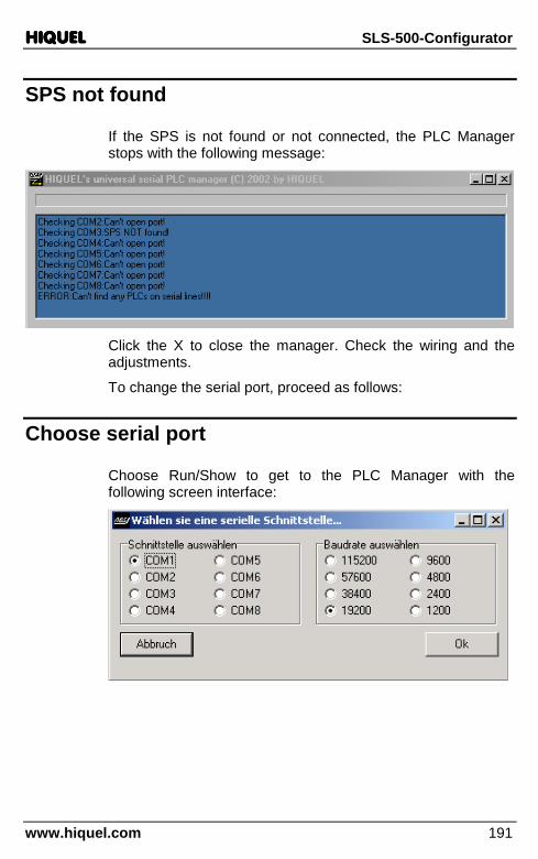
HIQUELHIQUELHIQUELHIQUEL SLS-500-Configurator
www.hiquel.com 191
SPS not found
If the SPS is not found or not connected, the PLC Manager stops with the following message:
Click the X to close the manager. Check the wiring and the adjustments.
To change the serial port, proceed as follows:
Choose serial port
Choose Run/Show to get to the PLC Manager with the following screen interface:

HIQUELHIQUELHIQUELHIQUEL SLS-500-Configurator
www.hiquel.com 192
If you click the button Research PLC, the PLC Manager will scan all available ports of the system to find an SLS500. If it is successful the following message will be displayed and the current communication parameters will be stored.
This happens in a file, which is stored in the temporary directory of Windows. The name of the file: RESISETTINGS.TMP
If you delete the file the PLC Manager will automatically scan for an SLS500 at the next start up.

HIQUELHIQUELHIQUELHIQUEL SLS-500-Configurator
www.hiquel.com 193

HIQUELHIQUELHIQUELHIQUEL SLS-500-Configurator
www.hiquel.com 194
Online Data exchange
Activating the button Debug at the PLC-Manager a test program will be activated with a screen interface that allows special actions:
Memory read/write
You can read many memories from the current program at the same time and set new values. Use the middle area of the test program.
Click the button Get values to query the current state of the memories.
You can also set a new value by choosing a Value and pressing Set values.
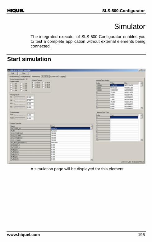
HIQUELHIQUELHIQUELHIQUEL SLS-500-Configurator
www.hiquel.com 195
Simulator The integrated executor of SLS-500-Configurator enables you to test a complete application without external elements being connected.
Start simulation
A simulation page will be displayed for this element.

HIQUELHIQUELHIQUELHIQUEL SLS-500-Configurator
www.hiquel.com 196
Simulation: Binary Memory
All binary memories of SPS will be displayed here.
The column Index describes the internal memory space of the marker. Name describes the name and Value shows you the current value.
To change the value of a memory double-click the field Index and the value will be inverted!
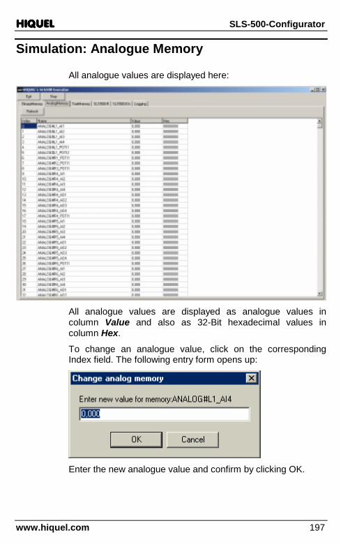
HIQUELHIQUELHIQUELHIQUEL SLS-500-Configurator
www.hiquel.com 197
Simulation: Analogue Memory
All analogue values are displayed here:
All analogue values are displayed as analogue values in column Value and also as 32-Bit hexadecimal values in column Hex.
To change an analogue value, click on the corresponding Index field. The following entry form opens up:
Enter the new analogue value and confirm by clicking OK.
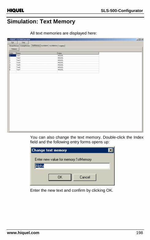
HIQUELHIQUELHIQUELHIQUEL SLS-500-Configurator
www.hiquel.com 198
Simulation: Text Memory
All text memories are displayed here:
You can also change the text memory. Double-click the Index field and the following entry forms opens up:
Enter the new text and confirm by clicking OK.
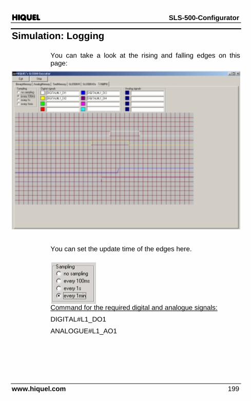
HIQUELHIQUELHIQUELHIQUEL SLS-500-Configurator
www.hiquel.com 199
Simulation: Logging
You can take a look at the rising and falling edges on this page:
You can set the update time of the edges here.
Command for the required digital and analogue signals:
DIGITAL#L1_DO1
ANALOGUE#L1_AO1

HIQUELHIQUELHIQUELHIQUEL SLS-500-Configurator
www.hiquel.com 200
Close Simulator
To close the executor click Exit on the upper left.
Continue Simulator
To activate the Simulator click Run, upper left.
Exit Simulator
To exit the Simulator click Exit, upper left.

HIQUELHIQUELHIQUELHIQUEL SLS-500-Configurator
www.hiquel.com 201
Contact
HIQUEL GmbH
Bair isch Köl ldorf 266,
A-8344 Bad Gleichenberg
Tel: +43-(0) 3159-3001-0
Fax: +43-(0)3159-3001-4
e-mail : [email protected]
http:/ /www.hiquel.com
Related Documents


