ATS-01 Ver1.0 AUTOMATIC TRANSFER SWITCH CONTROL UNIT OPERATOR’S MANUAL McPherson Controls 4501 NW 27 Ave Miami, Florida 33142 Ph 305-634-1511 Fax 305-634-1461

Welcome message from author
This document is posted to help you gain knowledge. Please leave a comment to let me know what you think about it! Share it to your friends and learn new things together.
Transcript

ATS-01 Ver1.0
AUTOMATIC TRANSFER SWITCH CONTROL UNIT
OPERATOR’S MANUAL
McPherson Controls 4501 NW 27 Ave
Miami, Florida 33142 Ph 305-634-1511 Fax 305-634-1461

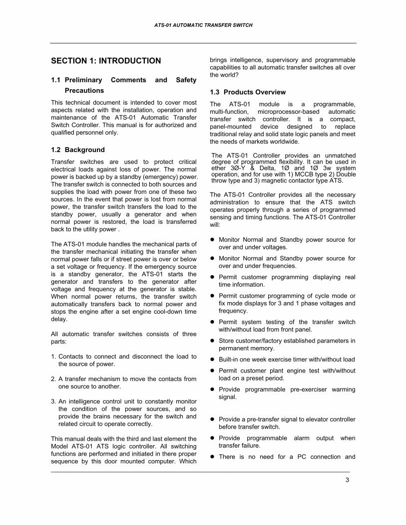
Mechanical Switch
Harness
Harness
All Voltages208 to 240 Volts
ONLY
All the Harnesses are manufactured in differentsizes and are readyto install
TSP-02

ATS-01 AUTOMATIC TRANSFER SWITCH
______________________________________________________________________________________
2
TABLE OF CONTENTS
Section Page
SECTOIN 1 : INTRODUCTION 1.1 Preliminary Comments and Safety Precautions ............................................................................ 3 1.2 Background ................................................................................................................................... 3 1.3 Product Overview .......................................................................................................................... 3 1.4 Functions / Features...................................................................................................................... 4
SECTOIN 2 : HARDWARE DESCRIPTION 2.1 General ......................................................................................................................................... 5 2.2 Display Window............................................................................................................................. 5 2.3 Operate Pushbuttons ................................................................................................................... 5 2.4 Panel LEDs Outputs .................................................................................................................... 5 2.5 Rear Access Area ........................................................................................................................ 5
SECTOIN 3 : OPERATOR PANEL 3.1 General ......................................................................................................................................... 8 3.2 Display Window............................................................................................................................. 8 3.3 Operate Pushbuttons .................................................................................................................... 8 3.4 Panel LED Outputs........................................................................................................................ 8
SECTOIN 4 : OPERATION 4.1 General ......................................................................................................................................... 9 4.2 Automatic Mode ............................................................................................................................ 9 4.3 Engine Test Mode ....................................................................................................................... 10 4.4 Off Mode ..................................................................................................................................... 10 4.5 Programming Mode..................................................................................................................... 10 4.6 Specification Summary................................................................................................................ 12
SECTOIN 5 : INSTALLATION INSTRUCTIONS 5.1 General ....................................................................................................................................... 12 5.2 Panel Cut-Out ............................................................................................................................ 12 5.3 Unit Dimensions ........................................................................................................................ 13
SECTOIN 6 : TYPICAL WIRING 6.1 General ....................................................................................................................................... 13 6.2 MCCB Type Wiring Diagram ....................................................................................................... 13 6.3 One Coil Double Throw Type Wiring Diagram............................................................................. 14 6.4 Two Coils Double Throw Type or Magnetic Contactor Type Wiring Diagram .............................. 14
ATS-01 AUTOMATIC TRANSFER SWITCH
______________________________________________________________________________________
3
SECTION 1: INTRODUCTION
1.1 Preliminary Comments and Safety Precautions
This technical document is intended to cover most aspects related with the installation, operation and maintenance of the ATS-01 Automatic Transfer Switch Controller. This manual is for authorized and qualified personnel only.
1.2 Background
Transfer switches are used to protect critical electrical loads against loss of power. The normal power is backed up by a standby (emergency) power. The transfer switch is connected to both sources and supplies the load with power from one of these two sources. In the event that power is lost from normal power, the transfer switch transfers the load to the standby power, usually a generator and when normal power is restored, the load is transferred back to the utility power .
The ATS-01 module handles the mechanical parts of the transfer mechanical initiating the transfer when normal power falls or if street power is over or below a set voltage or frequency. If the emergency source is a standby generator, the ATS-01 starts the generator and transfers to the generator after voltage and frequency at the generator is stable. When normal power returns, the transfer switch automatically transfers back to normal power and stops the engine after a set engine cool-down time delay.
All automatic transfer switches consists of three parts:
1. Contacts to connect and disconnect the load to the source of power.
2. A transfer mechanism to move the contacts from one source to another.
3. An intelligence control unit to constantly monitor the condition of the power sources, and so provide the brains necessary for the switch and related circuit to operate correctly.
This manual deals with the third and last element the Model ATS-01 ATS logic controller. All switching functions are performed and initiated in there proper sequence by this door mounted computer. Which
brings intelligence, supervisory and programmable capabilities to all automatic transfer switches all over the world?
1.3 Products Overview
The ATS-01 module is a programmable, multi-function, microprocessor-based automatic transfer switch controller. It is a compact, panel-mounted device designed to replace traditional relay and solid state logic panels and meet the needs of markets worldwide.
The ATS-01 Controller provides an unmatched degree of programmed flexibility. It can be used in ether 3Ø-Y & Delta, 1Ø and 1Ø 3w system operation, and for use with 1) MCCB type 2) Double throw type and 3) magnetic contactor type ATS.
The ATS-01 Controller provides all the necessary administration to ensure that the ATS switch operates properly through a series of programmed sensing and timing functions. The ATS-01 Controller will:
Monitor Normal and Standby power source for over and under voltages.
Monitor Normal and Standby power source for over and under frequencies.
Permit customer programming displaying real time information.
Permit customer programming of cycle mode or fix mode displays for 3 and 1 phase voltages and frequency.
Permit system testing of the transfer switch with/without load from front panel.
Store customer/factory established parameters in permanent memory.
Built-in one week exercise timer with/without load
Permit customer plant engine test with/without load on a preset period.
Provide programmable pre-exerciser warming signal.
Provide a pre-transfer signal to elevator controller before transfer switch.
Provide programmable alarm output when transfer failure.
There is no need for a PC connection and

ATS-01 AUTOMATIC TRANSFER SWITCH
______________________________________________________________________________________
4
programming software. Any and all changes can be made in the field.
Provide the source status and fail alarms indications on the front panel.
1.4 Functions / Features The primary function of ATS-01 Controller is to accurately monitor power sources and provide the necessary intelligence to operate a transfer switch in an appropriate and timely manner.
1.4.1 Operational Simplicity
From installation to programming to usage, the ATS-01 Controller is designed with operational simplicity. The controller operates with system voltage from 160 VAC to 480 VAC at 50 or 60 Hz. The user-friendly front panel interface simplifies routine operation, programming and setting adjustments.
1.4.2 Standard Features A variety of programmable features are available to meet wide application requirements. Individual features or feature combinations provide the intelligence required to tailor switches to individual needs. The features can be programmed by the customer. The specific variable set points associated with standard and factory activated features are stored in a non-volatile memory. All set points are customer adjustable.
Feature 1: Time Delay Normal to Emergency (TDNE) TDNE provides a time delay when transferring the Normal source to the Standby source. It ensures stability of the Standby source. Timing begins when the Standby Source becomes available.
Adjustable TDNE range: 0 ~ 300 sec.
Feature 2: Time Delay Engine Start (TDES) TDES delays the initiation of the engine start circuit in order to override momentary power outages or voltage fluctuations of the Normal source. The TDES timer shall start, when the Normal source becomes unavailable. If the Normal source becomes available while timing, the TDES timer will reset. The ATS-01
controller can perform the time delay engine start function without control power for 30 seconds.
Adjustable TDES range: 0 ~ 30 sec.
Feature 3: Time Delay Emergency to Normal (TDEN)
TDEN delays the transfer from the Standby source to the Normal Source to permit stabilization of the Normal Source before retransfer is made. Timing begins when the Normal Source becomes available.
Adjustable TDEN range: 0 ~ 300 sec.
Feature 4: Time Delay Engine Cool-down (TDEC) TDEC permits the generator to continue to run unloaded after retransfer to the Normal Source has occurred. Timing begins when the transfer to normal has been completed.
Adjustable TDEC range: 0 ~ 300 sec.
Feature 5: All Phase Under / Over voltage Sensing The controller monitors the voltage of each phase of the normal and standby power source. User adjustable settings are provided.
Adjustable Over voltage range: 110VAC ~ 550VAC
Adjustable Under voltage range: 80VAC ~ 470VAC
Feature 6: Under/Over frequency Sensing The controller monitors the frequency of the normal and standby power source. User adjustable settings are provided.
Adjustable Over frequency range: 51Hz ~ 70Hz
Adjustable Under frequency range: 45Hz ~ 47Hz
Feature 7: Plant Exerciser
This feature provides for automatic test operation of the generator. The interval is fixed at once per week with a specific test day and time. The test period is also programmable by custom settings. A LIGTED RED LED between VOLT & FREQ on the display window tells the operator the ATS is program to

ATS-01 AUTOMATIC TRANSFER SWITCH
______________________________________________________________________________________
5
NOTICEThe ATS-01 controller provides an auxiliary contactor for external signal output only. As such, this contactor just can define to one of the three features used. (Pre-transfer, Pre-exerciser or Transfer fail alarm signal output)
exercise the generator AND THAT GENERATOR CAN START AT ANY TIME.
Feature 8: Pre-transfer Signal Output When the auxiliary contactor is set to a pre-transfer signal output, the ATS-01 controller will provide a pre-transfer signal to the elevator controller before transferring the load from one source to another source, with a preset time delay. The pre-transfer returns to normal state after the transfer are complete.
Adjustable range: 0 ~ 99 sec.
Feature 9: Pre-exerciser Signal Output
When the auxiliary contactor is set to be a pre-exerciser signal output, the ATS-01 controller will provide a pre-transfer signal output before exercising the engine. It is a warning signal to avoid personal injury, before the generator auto starts itself.
Adjustable range: 0 ~ 99 sec.
Feature 10: Transfer Fail Alarm Output When the auxiliary contactor is set to be a transfer fail alarm output, the auxiliary contactor may be wired to a highly audible alarm panel to indicate problems with the Automatic Transfer Switch. An alarm condition will occur if a transfer has been initiated but is never completed. This may indicate that something is wrong with the motor or transfer
mechanism.
SECTION 2: HARDWARE DESCRIPTION
2.1 General
The purpose of this section is to familiarize the reader with ATS-01 hardware, its organization, and
to list the unit specifications. The information presented is divided into the following parts:
Front Display Window
Operate Pushbuttons
Panel LED Outputs
Rear Access Area
2.2 Display Window (Refer to Fig. 2-1)
A 4 digit 7-segment display is used to display all ATS-01 Controller monitored parameters, setting parameters and messages in easy to read formats.
For details concerning the kind of information that can be viewed in the display window refer to Paragraph 3.2.
2.3 Operate Pushbuttons (Refer to Fig. 2-1)
The front operator panel supports five long-life pushbuttons. Pushbuttons accomplish their function when pressed and released. Refer to Paragraph 3.3 for information concerning the function of specific pushbuttons.
2.4 Panel LEDs Outputs (Refer to Fig. 2-1) Thirteen individual LEDs are lit when performing or indicating a specific function. For detailed information on individual LEDs refer to Paragraph 3.4.
2.5 Rear Access Area (Refer to Figure 2-2) The rear access area of the ATS-01 Controller is normally accessible from the rear of panel. A wiring connection to the ATS-01 Controller is made at the rear of the chassis.
For detailed information of connecting wire diagram refer to Paragraph 6.

ATS-01 AUTOMATIC TRANSFER SWITCH
______________________________________________________________________________________
6
Figure 2-1
Front Panel
Display Window
Operator Pushbutton
ATS status LEDs

ATS-01 AUTOMATIC TRANSFER SWITCH
______________________________________________________________________________________
7
Figure 2-2
Rear

ATS-01 AUTOMATIC TRANSFER SWITCH
______________________________________________________________________________________
8
NOTICE
Although a wide variety of parameters and settings can be displayed, they are not displayed if they were not originally ordered and programmed into the panel..
SECTION 3: OPERATOR PANEL
3.1 General The operator panel, which is normally accessible from the outside of a panel or door, provides a means for being alerted to specific conditions, receiving functional help, programming and parameter monitoring.
3.2 Display Window The ATS-01 controller includes a 4 digits, 7-segment display to display all monitored parameters, setting parameters and messages in easy to read formats.
Different displays can be presented via the display window:
Normal source voltage and frequency parameter display
Standby source voltage and frequency parameter display
TDEN,TDNE and TDEC real time countdown display
Program setting parameter display
3.3 Operate Pushbuttons There are five front panel pushbuttons that accomplish their functions when pressed and released. Certain pushbuttons, like the increase ( )and decrease ( ) pushbuttons will also continue to scroll if they are pressed and not released during a programming procedure.
3.3.1 Increase ( ) Pushbutton When the ATS-01 controller operates at normal status, each depression of the increase ( ) key will change the real parameter display from one phase to another phase. When the user initiates the
program mode, each press of the increase ( ) key will scroll through all available parameters. When pressing and releasing the increase ( ) button, the displayed parameter can be increased by one. The increase ( ) pushbutton will continue to scroll if it is pressed and not released.
3.3.2 Decrease ( ) Pushbutton In the normal operating state, each depression of the decrease ( ) key will change the real parameter display between voltage and frequency. When the user initiates program mode, each depression of the Decrease ( ) key will scroll through all available parameters. When pressing and releasing the decrease ( ) button, the displayed parameter can be decreased by one. The decrease ( ) pushbutton will continue to scroll if it is pressed and not released.
3.3.3 Auto Function Pushbutton
Pushing the AUTO select key, the ATS-01 will run in automatic mode and a LED is provided to indicate the auto position. The ATS will transfer and retransfer from source to source, as dictated by the features supplied and their programmed setting values.
3.3.4 Test Function Pushbutton The ATS-01 is provided with a test pushbutton that simulates a loss of normal source. By pushing the TEST select key, the ATS-01 will run in engine test mode. An LED is provided to indicate the test position.
3.3.5 off Function Pushbutton By pushing the OFF select key, the ATS-01 will run in off mode. All the functions of the ATS-01 controller will be disabled.
When in program mode, pushing the off pushbutton allows the user to change the program line table and set the selected parameter using decrease ( ) or increase ( ) button.
3.4 Panel LED Outputs
Auto Position (Green) Indicates that the ATS-01 controller is set to AUTO function

ATS-01 AUTOMATIC TRANSFER SWITCH
______________________________________________________________________________________
9
Test Position (Green) Indicates that the ATS-01 controller is set to TEST function
Normal-Power Source Available (Green)
Indicates that the normal source is available, and the voltage and frequency are within the programmed parameters.
Normal-Power Source Connected (Green) Indicates that the transfer switch is connected to the normal source
Standby-Power Source Available (Green) Indicates that the standby source is available, and the voltage and frequency are within the programmed parameters.
Standby-Power Source Connected (Green) Indicates that the transfer switch is connected to the standby source
Building-Load Connected (Green) Indicates that the load is connected to the normal or standby source
Normal-Power over Voltage Fault (Red) Indicates that the normal source is unavailable, and the voltage is over the programmed parameters.
Normal-Power under Voltage Fault (Red) Indicates that the normal source is unavailable, and the voltage is below the programmed parameters.
Normal-Power over Frequency Fault (Red) Indicates that the normal source is unavailable, and the frequency is over the programmed parameters.
Normal-Power under Frequency Fault (Red) Indicates that the normal source is unavailable, and the frequency is below the programmed parameters.
Standby-Power over Voltage Fault (Red) Indicates that the standby source is unavailable, and the voltage is over the programmed
parameters.
Standby-Power under Voltage Fault (Red) Indicates that the standby source is unavailable, and the voltage is below the programmed parameters.
Standby-Power over Frequency Fault (Red) Indicates that the standby source is unavailable, and the frequency is over the programmed parameters.
Standby-Power under Frequency Fault(Red) Indicates that the standby source is unavailable, and the frequency is below the programmed parameters.
SECTION 4: OPERATION
4.1 General
This section specifically describes the operation and functional use of the ATS-01 Controller. It is divided into four main categories:
Automatic mode
Engine test mode
Off mode
Programming mode
The practical use of each operation under each category will be explained in this section. It is assumed that prior sections are understood, and the operator has a basic understanding of the hardware.
4.2 Automatic Mode The automatic mode of the ATS-01 Controller provides for automatic transfer and retransfers from source to source, as dictated by the features supplied and their programmed values.
The ATS-01 Controller constantly monitor the condition of both normal and standby power sources, thus providing the required intelligence for transfer operations.
For example, the ATS-01 Controller automatically initiates a transfer of power, when power fails or

ATS-01 AUTOMATIC TRANSFER SWITCH
______________________________________________________________________________________
10
when the voltage level drops below a preset value. Exactly what the Ats-01 controller will initiate in response to a given system condition, depends upon the combination of standard and selected optional features.
4.3 Engine Test Mode The ATS-01 is provided with a test pushbutton that simulates a loss of normal source. Pushing the TEST key on the front of panel, the ATS-01 will run in engine test mode. The TDES and TDNE programmed time delays will be performed as part of the Test. There are two pre-programmable test modes:
With load engine test.
Without load engine test. (The TDNE time delay will not be performed)
When the user terminates the engine test by pressing the AUTO pushbutton again, the controller will return to automatic mode. When normal power is available, the transfer switch automatically transfers back from standby source to normal source and initiates engine shutdown, after an engine cooling down time delay.
When the user terminates the engine test mode by pressing the OFF pushbutton, the ATS maintains the present status. The ATS-01 controller initiates engine shutdown immediately, without cooling down time delay, and returns to off mode.
4.4 Off Mode
The off mode of the ATS-01 Controller will disable all the transferred and protected functions. The display window and all the status LEDs will be turned off. In the event that power is lost from the normal source, the ATS-01 controller will not start the engine, and the ATS will not transfer the load to the standby source automatically.
When in program mode, pressing the off pushbutton allows the user to change the program line table and set the selected parameter using decrease ( ) or increase ( ) button.
4.5 Programming Instructions The ATS-01 Controller is fully programmable from the faceplate, once in the Programming Mode programming is very simple.
To get in programming mode, set the ATS-01on OFF, press buttons “increase ( ) & decrease ( ) ” together for 4 seconds. The word “ Vr 1.0 ” will appear on the front display window for 2 seconds, Indicating the version of the software.
You are now ready to start a line by line programming sequence. To advance to the next line, push the OFF button on the front panel. To change each line’s programming parameters, press the increase ( ) and decrease ( ) buttons. When pressing and releasing the increase ( ) or decrease ( ) key, the displayed parameter can be increased or decreased by one. The increase ( ) or decrease ( ) pushbutton will continue to scroll if it is pressed and not released.
Always push the “OFF” button to advance to the next programming line or until the word “END” appears on the screen. To immediately end programming, you simply push the “OFF ” button at any time and hold it for 4 seconds at any time. The word “End” on the display window indicates the end of the programming mode. Whatever you change is now in memory.
Should you make an error or desire to return to factory settings, stay in programming mode and simultaneously press all 3 buttons: increase ( ) ,decrease ( ) and OFF for 4 seconds. The ATS-01 controller will now automatically program itself to factory settings, and the word “Au.Po” will appear on the display window. (See line by line programming table for ATS-01 factory settings.)
Programming Line 1
The first thing the user needs to do is to key in the real line voltage into the ATS-01. Read the line voltage from the normal source from L1 to L3, on the ATS with a good quality digital voltmeter and key-in this volt into the ATS-01 on line 1 in programming mode. Using the ( ) and ( ) buttons.
If you are using Module TSP-1 you first plug is the voltage your ATS is going to work at 480, 380, 220, etc.
If you use Module TSP-02 you are limited to use in 208 to 240 Volts 1 to 3 phases.
The rest is easy, follow line by line programming..

ATS-01 AUTOMATIC TRANSFER SWITCH
______________________________________________________________________________________
11
LINE BY LINE PROGRAMMING TABLE
LINE DISCRIPTION VALUE Factory Setting
1 System voltage setting ( 90V ~ 600V ) Key in the real volt of normal side R & T 220V
2 Is this ATS operating in 1 phase, single phase with 3 wire, or 3 phase? 1) 1Ø 2) 1Ø 3W 3) 3Ø 3
3 Selected the Switch type of ATS 1) MCCB type 2) Double throw type 3) magnetic contactor type 1
4 Manual test with or without load 1) Test without load 2) Test with load 2
5 TDEN – Time delay emergency to normal 0 ~ 60 ( 0 ~ 300sec ) 1 unit = 5sec 2(10sec)
6 TDNE – Time delay normal to emergency 0 ~ 60 ( 0 ~ 300sec ) 1 unit = 5sec 2(10sec)
7 TDES – Time delay engine start 0 ~ 12 ( 0 ~ 60sec ) 1 unit = 5sec 1(5sec)
8 TDEC – Time delay engine cool-down 0 ~ 60 ( 0 ~ 300sec ) 1 unit = 5sec 12(60sec)
9 Normal source over voltage setting 11 ~ 55 ( 110V ~550V ) 25(250V)
10 Normal source under voltage setting 08 ~ 47 ( 80V ~ 470V ) 18(180V)
11 Time delay if there is a problem with normal source voltage output
0 ~ 99sec ( 0 = without voltage monitor function ) 10sec
12 Normal source over frequency setting 51 ~ 70Hz 65Hz 13 Normal source under frequency setting 45 ~ 59Hz 55Hz
14 Time delay if there is a problem with normal source frequency output
0 ~ 99sec ( 0 = without freq monitor function ) 10
15 Standby source over voltage setting 11 ~ 55 ( 110V ~550V ) 25(250V)
16 Standby source under voltage setting 8 ~ 47 ( 80V ~ 470V ) 18(180V)
17 Time delay if there is a problem with standby source voltage output
0 ~ 99sec ( 0 = without volt monitor function ) 10
18 Normal source over frequency setting 51 ~ 70Hz 65Hz 19 Normal source under frequency setting 45 ~ 59Hz 55Hz
20 Time delay if there is a problem with standby source frequency output
0 ~ 99sec ( 0 = without freq monitor function ) 10
21 Current day of week setting 1 ~ 7 (Mon to Sun) current 22 Current hour setting 00 ~ 23 current 23 Current minute setting 00 ~ 59 current 24 Plant exerciser test day of week 1 ~ 7 (Mon to Sun) 6(Sat) 25 Plant exerciser hour 00 ~ 23 1226 Plant exerciser minute 00 ~ 59 0027 Engine run time on exerciser 0 ~ 60 min ( 0 = without exerciser function ) 028 Exerciser test with or without load 1) without load 2) with load 129 Display mode setting 1) cyclic mode 2) fix mode 1
30 Auxiliary contactor feature (the contactor can only define one of the three features)
1) transfer fail alarm 2) pre-transfer signal 3) pre-exerciser signal 2
31 Pre-transfer time delay Line 30 option 2. Can be used for elevator Pre-Transfer signal
0 ~ 99 sec ( 0 = without pre-transfer function) 10
32 Pre-exerciser time delay before engine exerciser test. Line 30 option 3 Can be used for engine start alarm
0 ~ 99 sec ( 0 = without pre-exerciser function) 10
ATS-01 AUTOMATIC TRANSFER SWITCH
______________________________________________________________________________________
12
4.6 Specification Summary
PARAMETER SPECIFICATION Input Control Voltage 160 VAC to 250 VAC 50/60 Hz
Voltage Measurement Range 80 VAC to 600 VAC 50/60 HZ
Frequency Measurement Range 45HZ to 70HZ
Generator Start Relay 7A @ 250VAC Max
Transfer to Normal Relay 7A @ 250VAC Max
Transfer to Standby Relay 7A @ 250VAC Max
Auxiliary Relay 0.5A @ 120VAC 1.0A @ 24VDC
Operating Temperature -20°C ~ 70(C Storage Temperature -35(C ~ 85(C Operating Humidity 0 to 95% relative humidity
SECTION 5: INSTALLATION INSTRUCTIONS
5.1 General
The ATS-01 controller has been designed for front panel mounting.
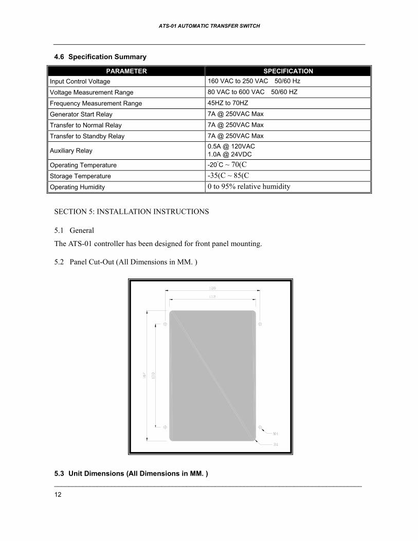
5.2 Panel Cut-Out (All Dimensions in MM. )
�
5.3 Unit Dimensions (All Dimensions in MM. )

ATS-01 AUTOMATIC TRANSFER SWITCH
______________________________________________________________________________________
13
SECTION 6: TYPICAL WIRING
6.1 General It is dangerous to feed high voltage to the ATS-01 Printed Circuit boards. The ATS-01 controller operates with system voltage from 160 VAC t0 250
VAC at 50 or 60 Hz. To work at over 250VAC volts, we have developed a clear and simple transformer module TSP-01 that provides the safety control and
operating voltages. User just needs to key in the real voltage (Step 1in programming mode) values of normal source L1 ~ L3. The ATS-01 controller will follow the scale between input volt and key in volt and show the correct voltage on the display window.
The ATS-01 maximum work current is 6 Amps,. When working currents are over 6 Amps, two external power relays are recommended. (The connecting wire diagram refers to 6.5 sections.)

ATS-01 AUTOMATIC TRANSFER SWITCH
______________________________________________________________________________________
14
6.2 3Phase 3Wire connecting wire diagram
6.2.1 MCCB Type Wiring Diagram
6.2.2 One Coil Double Throw Typical Wiring Diagram

ATS-01 AUTOMATIC TRANSFER SWITCH
______________________________________________________________________________________
15
6.2.3 Two Coil Double Throw Type or Magnetic Contactor Type Diagram
6.3 1Phase 3Wire connecting wire diagram
6.3.1 MCCB Type Wiring Diagram

ATS-01 AUTOMATIC TRANSFER SWITCH
______________________________________________________________________________________
16
6.3.2 One Coil Double Throw Typical Wiring Diagram
6.3.3 Two Coil Double Throw Type or Magnetic Contactor Type Diagram

ATS-01 AUTOMATIC TRANSFER SWITCH
______________________________________________________________________________________
17
6.4 Single Phase system connecting wire diagram
6.4.1 MCCB Type Wiring Diagram
6.4.2 One Coil Double Throw Typical Wiring Diagram

ATS-01 AUTOMATIC TRANSFER SWITCH
______________________________________________________________________________________
18
6.4.3 Two Coil Double Throw Type or Magnetic Contactor Type Diagram
6.5 Connecting wire diagram When the switch transfer current over 6 Amps
6.5.1 MCCB Type Wiring Diagram (PT1 & PT2 are unnecessary for AC220 system)

ATS-01 AUTOMATIC TRANSFER SWITCH
______________________________________________________________________________________
19
6.5.2 One Coil Double Throw Typical Wiring Diagram (PT1 & PT2 are unnecessary for AC220 system)
6.5.3 Two Coil Double Throw Type or Magnetic Contactor Type Diagram (PT1 & PT2 are unnecessary for AC220 system)
6.2

1 3 2 7 8 52 52 10 9 5 4 6

TSP-01 ATS Transformer Module With Multi-Voltage Plug-In Connectors to Simplify ATS Set-Up Features Use In System Voltage From 200 ~ 600 VAC Simplifies All ATS Wiring Connects to BTS* & ATS-01* By Plug-In ConnectorsSelect Voltage Directly By Plug-In Connectors Save Labor Cost By Easy Assembly & MaintenanceCircuits Are Finger Safe With High Voltage Fuses & Epoxy Protection Built-In 3 Phase Fuses To Protect Normal & Emergency Circuits in ATS-01 & TSP-01 Provides Alarms Signals & Engine Start Contacts
SpecificationsFuse Function Current Fuse Capacity Connector Function Capacity
F1 Protect Normal Power Circuit 6.3 A 50KA @ 500 VAC Remote Start Remote engine start 250 VAC / 7A
F2 Protect Normal Power Circuit 1.0 A 50KA @ 500 VAC Prog. Output Programmable alarm signal output 120VAC / 0.5A
F3 Protect Normal Power Circuit 6.3 A 50KA @ 500 VAC TB2 Connect to ATS-01 300 VAC / 1 AF4 Protect Emergency Power Circuit 6.3 A 50KA @ 500 VAC CN2 Connect to BTS 600 VAC / 8A
F5 Protect Emergency Power Circuit 1.0 A 50KA @ 500 VAC
F6 Protect Emergency Power Circuit 6.3 A 50KA @ 500 VACCN3 CN4CN5 CN6
Connect to transformers 600 VAC / 8A
Mechanical Specifications
TB2-From ATS-01
CN
2-From B.T.S.
208V
380V
440V
460V
F1F2
F3
F5F4
F6
CN
3
CN
4C
N6
CN
5
TB3
NC
.C
NO
.N
O.
CN
C.
Rem
ote StartProg. O
utput
Plug-In Connectors Range Universal Voltages
208 VAC ±10% 208, 220, 240
380 VAC ±10% 365, 380, 401
440 VAC ±10% 415, 440
460VAC ±10% 460, 480 Physical Specifications
Dimensions 280 (L) x 166 (W) x 152 (H) mm
Weight 5.5 Kg ± 2%
* BTS Basic Transfer Switch
* ATS-01 Intelligent ATS Controller
Notes:
1. The Rate Capacity of TSP-01 is 105 VA
2. If the system voltage is from 200~240, transformer
model is not needed—Use TSP-02.
UNIT: mm
Related Documents