Welcome message from author
This document is posted to help you gain knowledge. Please leave a comment to let me know what you think about it! Share it to your friends and learn new things together.
Transcript
1ATR's Arti�cial Brain Project:CAM-Brain Machine (CBM) and RobotKitten (Robokoneko) Issues
Michael KORKIN (1), Hugo de GARIS (2), N. Eiji NAWA (2), William Dee RIEKEN (2)(1) Genobyte Inc., 1503 Spruce St., Suite 3, Boulder, CO 80302, USA.tel.+1 303 545 6790, fax. +1 303 545 9667http://[email protected]@internetphone.com(2) Brain Builder Group, Evolutionary Systems Dept., ATR Research Labs,2-2 Hikaridai, Seika-cho, Soraku-gun, Kyoto, JAPAN.tel. +81 774 95 1079, fax. +81 774 95 1008http://www.hip.atr.co.jp/�fdegaris, xnawa, wriekengfdegaris, xnawa, [email protected]@internetphone.com [email protected]: Arti�cial Brain, Cellular Automata, Neural Networks, Evolvable Hardware,CAM-Brain Machine, Robot Kitten
July 6, 1998 DRAFT
2 ATR's Arti�cial Brain Project: CAM-Brain Machine (CBM) and Robot Kitten (Robokoneko) IssuesAbstractThis paper presents some ongoing issues concerning ATR's Arti�cial Brain (CAM-Brain) Project. The CAM-Brain Project evolves 3D cellular automata (CA) based neural networks directly in FPGA electronics at electronicspeeds in special hardware called a CAM-Brain Machine (CBM). The CBM updates the CA cells at a rate of 150Billion a second, and can perform a full run of a genetic algorithm (GA) in about 1 second. 32K of these evolvedcircuits (modules) are then assembled (in a large RAM space updated in real-time by the CBM) into humanlyde�ned architectures to make an arti�cial brain to control a robot kitten ("Robokoneko"). The paper presents anddiscusses the latest design decisions for the CBM and the kitten robot, and maps out future plans aimed at havingan arti�cial-brain-controlled robot kitten playing in the ATR labs by early 2001. A world wide, many membered,internet-videophone and electronic pen based, brain-architectural design and brainstorming group will be essentialfor distributing the design and evolution of the 32K modules. Designing and building an arti�cial brain withinthe next three years will be a major conceptual and managerial challenge.KeywordsArti�cial Brain, Cellular Automata, Neural Networks, Evolvable Hardware, CAM-Brain Machine, Robot Kit-ten. I. IntroductionThis paper discusses ongoing issues concerning ATR's Arti�cial Brain (CAM-Brain) Project [1], speci�-cally, the latest (June 1998) design decisions concerning the CAM-Brain Machine (CBM) [3] and the robotkitten ("Robokoneko"). Sections 1-4 of this paper deal with the CBM. Section 5 discusses design aspectsof the robot kitten and its interface with the CBM. Section 6 presents our Brain Builder Group's plans tohave an arti�cial-brain-controlled robot kitten running around ATR labs by early 2001. With 32K modulesto specify and evolve, a large international team e�ort will be necessary. We believe that our use of thenew internet videophone technology to create such a team is innovative and essential, if we are to meetthe deadline.(The research project funding terminates early 2001).We begin with a general introduction to the CAM-Brain Project as a whole, then describe the CBMdesign parameters in reasonable detail.The CAM-Brain Machine (CAM stands for Cellular AutomataMachine) is a research tool for the simulation of arti�cial brains. An original set of ideas for the CAM-Brain project was developed by Dr. Hugo de Garis at the Evolutionary Systems Department of ATRHIP (Kyoto, Japan), and is currently being implemented as a dedicated research tool by Genobyte, Inc.(Boulder, Colorado).An arti�cial brain, supported by the CBM, consists of up to 32,768 neural modules, each modulepopulated with up to 1,152 neurons, a total of 37.7 million neurons. Within each neural module, neuronsare densely interconnected with branching dendritic and axonic trees in a three-dimensional space, formingan arbitrarily complex interconnection topology. A neural module can receive e�erent axons from up to92 other modules of the brain, with each axon being capable of multiple branching in three dimensions,forming hundreds of connections with dendritic branches inside the module. Each module sends a�erentaxon branches to up to 32,768 other modules.A critical part of the CBM approach is that neural modules are not "manually designed" or "engineered"to perform a speci�c brain function, but rather evolved directly in hardware, using genetic algorithms.DRAFT July 6, 1998
3Genetic algorithms operate on a population of chromosomes, which represent neural networks of dif-ferent topologies and functionalities. Better performers for a particular function are selected and furtherreproduced using chromosome recombination and mutation. After hundreds of generations, this approachproduces very complex neural networks with a desired functionality. The evolutionary approach can createa complex functionality without any a priori knowledge about how to achieve it, as long as the desiredinput/output function is known. II. CBM Neural ModelThe CBM implements a so called "CoDi" (i.e. Collect and Distribute) [2] neural model. It is a simpli�edcellular automata based neural network model developed at ATR HIP (Kyoto, Japan) in the summer of1996 with two goals in mind. One was to make neural network functioning much simpler and morecompact compared to the original ATR HIP model, to achieve considerably faster evolution runs on theCAM-8 (Cellular Automata Machine), a dedicated hardware tool developed at Massachusetts Institute ofTechnology in 1989.In order to evolve one neural module, a population of 30-100 modules is run through a genetic al-gorithm for 200-600 generations, resulting in up to 60,000 di�erent module evaluations. Each moduleevaluation consists of - �rstly, growing a new set of axonic and dendritic trees, guided by the module'schromosome. These trees interconnect several hundred neurons in the 3D cellular automata space of 13,824cells (24*24*24). Evaluation is continued by sending spiketrains to the module through its e�erent axons(external connections) to evaluate its performance (�tness) by looking at the outgoing spiketrains. Thistypically requires up to 1000 update cycles for all the cells in the module.On the MIT CAM-8 machine, it takes up to 69 minutes to go through 829 billion cell updates neededto evolve a single neural module, as described above. A simple "insect- like" arti�cial brain has hundredsof thousands of neurons arranged into ten thousand modules. It would take 500 days (running 24 hours aday) to �nish the computations.Another limitation was apparent in the full brain simulation mode, involving thousands of modulesinterconnected together. For a 10,000-module brain, the CAM-8 is capable of updating every module atthe rate of one update cycle 1.4 times a second. However, for real time control of a robotic device, anupdate rate of 50-100 cycles per module, 10-20 times a second is needed. So, the second goal was tohave a model which would be portable into electronic hardware to eventually design a machine capable ofaccelerating both brain evolution and brain simulation by a factor of 500 compared to CAM-8.The CoDi model operates as a 3D cellular automata (CA). Each cell is a cube which has six neighborcells, one for each of its faces. By loading a di�erent phenotype code into a cell, it can be recon�guredto function as a neuron, an axon, or a dendrite. Neurons are con�gurable on a coarser grid, namely oneper block of 2*2*3 CA cells. Cells are interconnected with bidirectional 1-bit buses and assembled into 3Dmodules of 13,824 cells (24*24*24).Modules are further interconnected with 92 1-bit connections to function together as an arti�cial brain.Each module can receive signals from up to 92 other modules and send its output signals to up to 32,768modules. These intermodular connections are virtual and implemented as a cross-reference list in a moduleJuly 6, 1998 DRAFT

4interconnection memory (see below).In a neuron cell, �ve (of its six) connections are dendritic inputs, and one is an axonic output. A 4-bitaccumulator sums incoming signals and �res an output signal when a threshold is exceeded. Each of theinputs can perform an inhibitory or an excitatory function (depending on the neuron's chromosome) andeither adds to or subtracts from the accumulator. The neuron cell's output can be oriented in 6 di�erentways in the 3D space. A dendrite cell also has �ve inputs and one output, to collect signals from othercells. The incoming signals are passed to the output with an 5-bit XOR function. An axon cell is theopposite of a dendrite. It has 1 input and 5 outputs, and distributes signals to its neighbors. The "Collectand Distribute" mechanism of this neural model is re ected in its name "CoDi". Blank cells perform nofunction in an evolved neural network. They are used to grow new sets of dendritic and axonic trees duringthe evolution mode.Before the growth begins, the module space consists of blank cells. Each cell is seeded with a 6-bitchromosome. The chromosome will guide the local direction of the dendritic and axonic tree growth. Sixbits serve as a mask to encode di�erent growth instructions, such as grow straight, turn left, split intothree branches, block growth, T- split up and down etc. Before the growth phase starts, some cells areseeded as neurons at random locations. As the growth starts, each neuron continuously sends growthsignals to the surrounding blank cells, alternating between "grow dendrite" (sent in the direction of futuredendritic inputs) and "grow axon" (sent towards the future axonic output). A blank cell which receivesa growth signal becomes a dendrite cell, or an axon cell, and further propagates the growth signal, beingcontinuously sent by the root neuron, to other blank cells. The direction of the propagation is guided bythe 6-bit growth instruction, described above. This mechanism grows a complex 3D system of branchingdendritic and axonic trees, with each tree having one neuron cell associated with it. The trees can conductsignals between the neurons to perform complex spatio-temporal functions. The end-product of the growthphase is a phenotype bitstring which encodes the type and spatial orientation of each cell.III. CBM ArchitectureThe CBM consists of the following six major blocks:1. Cellular Automata Module2. Genotype/Phenotype Memory3. Fitness Evaluation Unit4. Genetic Algorithm Unit5. Module Interconnection Memory6. External InterfaceEach of these blocks is discussed in detail below.A. Cellular Automata ModuleThe cellular automata module is the hardware core of the CBM. It is intended to accelerate the speed ofbrain evolution through a highly parallel execution of cellular state updates. The CA module consists ofan array of identical hardware logic circuits or cells arranged as a 3D structure of 24*24*24 cells (a totalDRAFT July 6, 1998

5of 13,824 cells). Cells forming the top layer of the module are recurrently connected with the cells in thebottom layer. A similar recurrent connection is made between the cells on the north and south, east andwest vertical surfaces. Thus a fully recurrent toroidal cube is formed. This feature allows a higher axonicand dendritic growth capacity by e�ectively doubling each of the three dimensions of the cellular space.The CBM hardware core is time-shared between multiple modules forming a brain during brain simula-tion. Only one module is instantiated at a time. The FPGA �rmware design is a dual-bu�ered structure,which allows simultaneous con�guration of the next module while the current module is being run (i.e.signals are propagated through the dendrites and axons between neurons). Thus, the FPGA core is runcontinuously without any idle time between modules for recon�guration.The surfaces of the cube have external connections to provide signal input from other modules. Eachsurface has a matrix of 32 signals, which is repeated on the opposite surface due to wrap around connections.Thus, a total of 96 di�erent connections is available. Four connections on one of the surfaces are used asoutput points.The CA module is implemented with new Xilinx FPGA devices XC6264. These devices are fully andpartially recon�gurable, feature a new co-processor architecture with data and address bus access inaddition to user inputs and outputs, and allow the reading and writing of any of the internal ip- opsthrough the data bus. An XC6264 FPGA contains 16384 logic function cells, each cell featuring a ip- opand Boolean logic capacity, capable of toggling at a 220 MHz rate. Logic cells are interconnected withneighbors at several hierarchical levels, providing identical propagation delay for any length of connection.This feature is very well suited for a 3D CA space con�guration. Additionally, clock routing is optimizedfor equal propagation time, and power distribution is implemented in a redundant manner.To implement the CA module, a 3D block of identical logic cells is con�gured inside each XC6264device, with CoDi speci�ed 1-bit signal buses interconnecting the cells. Given the FPGA internal routingcapabilities and the logic capacity needed to implement each cell, the optimal arrangement for a XC6264is 4*6*8 (192 cells). This elementary block of cells requires 208 external connections to form a larger 3Dblock by interconnecting with six neighbor FPGAs on the south, north, east, west, top, and bottom sidesin a virtual 3D space. A total of 72 FPGAs, arranged as a 6*4*3 array are used to implement a 24*24*24cellular cube.The CBM implements interconnections between 72 FPGAs, each placed on a small individual printedcircuit board, in the form of one large backplane board, carrying all 72 FPGA daughter boards.The CBM clock rate for cellular update is selected between 8.25 MHz, 9.42 MHz, and 11 MHz. Atthis rate all 13,824 cells are updated simultaneously, which results in the update rate of 114 to 152 billioncells/s. This rate exceeds the CAM-8 update rate by a factor of 570 to 751 times.B. Genotype and Phenotype MemoryEach of the 72 FPGA daughter boards includes 8 Mbytes of EDO DRAM to be used for storing thegenotypes and phenotypes of the neural modules, a total of 576 Mbytes. There are two modes of CBMoperation, namely evolution mode and run mode. The evolution mode involves the growth phase andsignaling phase. During the growth phase, memory is used to store the chromosome bitstrings of theJuly 6, 1998 DRAFT
6evolving population of modules (module genotypes). For a module of 13,824 cells there are over 91 Kbitsof genotype memory needed. For each module the genotype memory also stores information concerningthe locations and orientations of the neurons inside the module, and their synaptic masks.During the run mode, memory is used as a phenotype memory for the evolved modules. The phenotypedata describes the grown axonic and dendritic trees and their respective neurons for each module. Thephenotype data is loaded into the CA module to con�gure it according to the evolved function. The geno-type/phenotype memory is used to store and rapidly recon�gure (reload) the FPGA hardware CA module.Recon�guration can be performed in parallel with running the module, due to a dual pipelined pheno-type/genotype register provided in each cell. This guarantees the continuous running of the FPGA arrayat full speed with no interruptions for reloading in either evolution or run modes. The phenotype/genotypememory can support up to 32,758 modules at a time. An additional memory will be based in the mainmemory of the host computer (Pentium-Pro 300 MHz) connected to the CBM through a PCI bus, capableof transferring data at 132 Mbytes/s.C. Fitness Evaluation UnitSignaling in the CBM is accomplished with 1-bit spiketrains, a sequence of ones separated by intervals ofzeros, similar to those of biological neural networks. Information, representing external stimuli, as well asinternal waveforms, is encoded in spiketrains using a so-called "Spike Interval Information Coding (SIIC)".This method of coding is implemented by nature in animal neural networks, and is very e�cient in terms ofinformation capacity per spike. Conversion from spiketrains into "analog" waveforms representing externalstimuli, or internal signaling, is accomplished by convolving the spiketrain with a special multi-tap linear�lter.When a module is being evolved, each instance of a module must be evaluated in terms of it's �tnessfor a targeted task. During the signaling phase, each module receives up to 92 di�erent spiketrains, andproduces up to four di�erent output spiketrains, which is compared with a target array of spiketrains inorder to guide the evolutionary process. This comparison gives a measure of performance, or �tness, ofthe module.Fitness evaluation is supported by a hardware unit which consists of an input spiketrain bu�er, a targetspiketrain bu�er, and a �tness evaluator. During each clock cycle an input vector is read from its stackand fed into module's inputs. At the same time, a target vector is read from its bu�er to be compared withthe current module outputs by the evaluator. The �tness evaluator performs convolution of the spiketrainswith the convolution �lter, and computes the sum of waveform's absolute deviations for the duration ofthe signaling phase. At the end of the signaling phase, a �nal measure of the module's �tness is instantlyavailable.D. Genetic Algorithm UnitTo evolve a module, a population of modules is evaluated by computing every module's �tness measure,as described above. A subset of best modules are then selected for further reproduction. In each generationof modules, the best are mated and mutated to produce a set of o�spring modules to become the nextDRAFT July 6, 1998
7generation. Mating and mutation is performed by the CBM hardware core at high speed, con�gured forthe genetic phase.During this phase, each cell's �rmware implements crossover and mutation masks, two parent registersand an o�spring register. Thus, each o�spring chromosome is generated in nanoseconds, directly in hard-ware. Selection algorithm is performed by the host computer in software, using access to CBM via PCIinterface.E. Module Interconnection MemoryIn order to support the run mode of operation, which requires a large number of evolved modules tofunction as one arti�cial brain, a module interconnection memory is provided. Each module can receiveinputs from up to 92 other modules. A list of these source modules referenced to each module is stored ina CBM cross-reference memory (3 Mbytes) by the host computer. This list is compiled by CBM softwareusing module interconnection netlist in EDIF format. This netlist re ects module interconnections asdesigned by the user, using o�-the-shelf schematic capture tools.The length of module interconnections is 64 cells (clock cycles). For each of the 32,768 modules, a SignalMemory stores up to four 64-bit long output spiketrains, a total of 256 Kbytes.During the run mode, at the time each module of a brain is con�gured in the CA hardware core (byloading its phenotype), a signal input bu�er is also loaded with up to 92 spiketrains according to thecross-reference list in the cross-reference memory. The spiketrains are the signals saved from the previousinstantiation and signaling of the 92 sourcing modules. At the same time,the four output spiketrains ofthe currently instantiated module are saved back to the Signal Memory. Thus repetitive cycling throughall the modules forming the brain results in repetitive saving and retrieving of the spiketrains to/fromthe Signal Memory, providing signaling between modules according to the brain interconnection structurere ected in the schematics, designed by the user.In a maximum brain with 32,768 modules, CBM update rate is such that each cell propagates approxi-mately 320 bit-long spiketrains per second. A 320 bit-long spiketrain can carry on the order of 15 bytes ofsignal information, using SIIC coding method. Each neuron receives up to 5 spiketrains, so there are upto 188 million spiketrains being processed by neurons in the brain. Thus the information processing rateby all neurons in the brain is on the order of 2.8 Gbytes/s. This number does not include processing inmultiple dendrite branches.F. External InterfaceCBM architecture allows to receive and send spiketrains not only from/to the Signal Memory, but alsofrom/to external CBM interface. Any module can receive up to 92 incoming spiketrains and send up to 4spiketrains to an external device, such as a robot, a speech processing system, etc. In a brain with 16,384modules, the information rate, as measured at the external interface is up to 2.8 Kbytes/s per each module,or up to 46.7 Mbyte/s overall. In a brain with less modules, the external information rate is higher, forexample, a brain with 4,000 modules provides quadruple external information rate for each module ( 11.2Kbyte/s).July 6, 1998 DRAFT

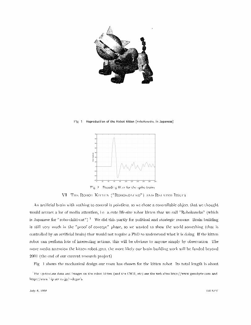
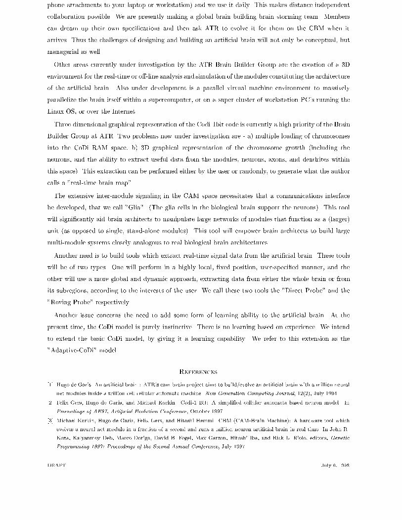
8 IV. Summary of CBM technical specifications� Cellular automata update rate (max.): 152 billion/s.� Number of supported neurons (per module): 1,152.� Number of supported neurons (per brain): 37,748,736.� Number of supported neural modules: 32,768.� Information ow rate, neuronal level (max.): 2.8 Gbytes/s.� Information ow rate, intermodular level (max.): 46.7 Mbytes/s.� Number of FPGAs: 72.� Number of FPGA recon�gurable function units: 1,179,648.� Chromosome length: 91,008 bits.� Power consumption: 1 KWatt (5 V, 200 A).V. Choosing a Representation for the CoDi-1Bit SignalingThe constraints imposed by state-of-the-art programmable (evolvable) FPGAs in 1998 are such thatthe CA based model (the CoDi model) had to be very simple in order to be implementable within thoseconstraints. Consequently, the signaling states in the model were made to contain only 1 bit of information(as happens in nature's "binary" spike trains). The problem then arose as to interpretation. How were weto assign meaning to the binary pulse streams (i.e. the clocked sequences of 0s and 1s which are a neuralnet module's inputs and outputs? We tried various ideas such as a frequency based interpretation, i.e.count the number of pulses (i.e. 1s) in a given time window (of N clock cycles). But this was thought tobe too slow. In an arti�cial brain with tens of thousands of modules which may be vertically nested toa depth of 20 or more (i.e. the outputs of a module in layer "n" get fed into a module in layer "n+1",where "n" may be as large as 20 or 30) then the cumulative delays may end up in a total response timeof the robot kitten being too slow (e.g. if you wave your �nger in front of its eye, it might react manyseconds later). We wanted a representation that would deliver an integer or real valued number at eachclock tick, i.e. the ultimate in speed. The �rst such representation we looked at we called "unary" i.e.if N neurons on an output surface are �ring at a given clock tick, then the �ring pattern represented theinteger N, independently of where the outputs were coming from. We found this representation to be toostochastic, too jerky. Ultimately we chose a representation which convolves the binary pulse string withthe convolution function shown in Fig.2. We call this representation "SIIC" (Spike Interval InformationCoding) which was inspired by [5]. This representation delivers a real valued output at each clock tick, thusconverting a binary pulse string into an analog time dependent signal. Our team has already publishedmany papers on the results of this convolution representation work [4]. Figs. 3 and 4 show some results ofCoDi modules which were evolved to output oscillatory signals (using the convolutionary interpretation).Fig. 5 show the evolved output for a random target analog signal. We thought the results were goodenough to settle on this representation. The CBM will implement this representation in the FPGAs whenmeasuring �tness values at electronic speeds.DRAFT July 6, 1998
9
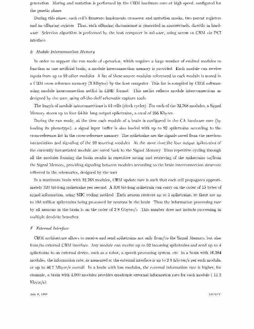
Fig. 1. Reproduction of the Robot kitten (robokoneko, in Japanese)0 20 40 60 80 100 120 140 160 180 200
−30
−20
−10
0
10
20
30
40
50
60
70
Filt
er A
mpl
itude
Fig. 2. Decoding �lter for the spike trains.VI. The Robot Kitten ("Robokoneko") and Related IssuesAn arti�cial brain with nothing to control is pointless, so we chose a controllable object that we thoughtwould attract a lot of media attention, i.e. a cute life-size robot kitten that we call "Robokoneko" (whichis Japanese for "robo-child-cat") 1. We did this partly for political and strategic reasons. Brain buildingis still very much in the "proof of concept" phase, so we wanted to show the world something (that iscontrolled by an arti�cial brain) that would not require a PhD to understand what it is doing. If the kittenrobot can perform lots of interesting actions, this will be obvious to anyone simply by observation. Themore media attention the kitten robot gets, the more likely our brain building work will be funded beyond2001 (the end of our current research project).Fig. 1 shows the mechanical design our team has chosen for the kitten robot. Its total length is about1For up-to-date data and images on the robot kitten (and the CBM, etc) see the web sites http://www.genobyte.com andhttp://www.hip.atr.co.jp/�degarisJuly 6, 1998 DRAFT
100 50 100 150 200 250
0
0.5
1
0 50 100 150 200 250
−1
−0.8
−0.6
−0.4
−0.2
0
0.2
0.4
0.6
0.8
1
0 50 100 150 200 2500
0.5
1
0 50 100 150 200 250
−1
−0.5
0
0.5
1
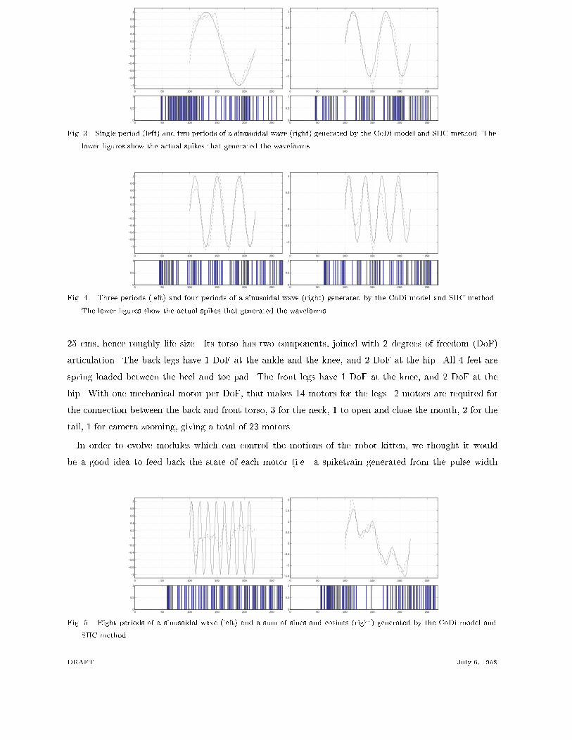
Fig. 3. Single period (left) and two periods of a sinusoidal wave (right) generated by the CoDi model and SIIC method. Thelower �gures show the actual spikes that generated the waveforms.0 50 100 150 200 250
0
0.5
1
0 50 100 150 200 250
−1
−0.8
−0.6
−0.4
−0.2
0
0.2
0.4
0.6
0.8
1
0 50 100 150 200 2500
0.5
1
0 50 100 150 200 250
−1
−0.5
0
0.5
1
Fig. 4. Three periods (left) and four periods of a sinusoidal wave (right) generated by the CoDi model and SIIC method.The lower �gures show the actual spikes that generated the waveforms.25 cms, hence roughly life size. Its torso has two components, joined with 2 degrees of freedom (DoF)articulation. The back legs have 1 DoF at the ankle and the knee, and 2 DoF at the hip. All 4 feet arespring loaded between the heel and toe pad. The front legs have 1 DoF at the knee, and 2 DoF at thehip. With one mechanical motor per DoF, that makes 14 motors for the legs. 2 motors are required forthe connection between the back and front torso, 3 for the neck, 1 to open and close the mouth, 2 for thetail, 1 for camera zooming, giving a total of 23 motors.In order to evolve modules which can control the motions of the robot kitten, we thought it wouldbe a good idea to feed back the state of each motor (i.e. a spiketrain generated from the pulse width
0 50 100 150 200 2500
0.5
1
0 50 100 150 200 250
−1
−0.8
−0.6
−0.4
−0.2
0
0.2
0.4
0.6
0.8
1
0 50 100 150 200 250
−1.5
−1
−0.5
0
0.5
1
1.5
2
0 50 100 150 200 2500
0.5
1Fig. 5. Eight periods of a sinusoidal wave (left) and a sum of sines and cosines (right) generated by the CoDi model andSIIC method.DRAFT July 6, 1998

11modulation PWM output value of the motor) into the controlling module. Since each module can have upto 92 inputs (actually, 32 inputs repeated 3 times and distributed over three of the input surfaces of themodule (minus 4 inputs positions reserved for the 4 output slots) feeding in these 23 motor state valueswill not be di�cult. We are thinking we may install acceleromotors and/or gyroscopes which may addanother 6 or more inputs to each motion control module. It can thus be seen that the mechanical design ofthe kitten robot has implications on the design of the CBM modules. There need to be su�cient numbersof inputs for example.The motion control modules will not be evolved directly using the mechanical robot kitten. This wouldbe hopelessly too slow. Mechanical �tness measurement is impractical for our purposes. Instead we willsoon be simulating the kitten's motions using an elaborate commercial simulation software package called"Working Model - 3D". This software will allow input from an evolving module to control the simulatedmotors of the simulated kitten. But, does not this approach rather destroy the whole philosophy ofthe CAM-Brain Machine and the CAM-Brain Project? It is a compromise, certainly, but in practice, theproportion of modules concerned with motion control will be very small compared to the total. Potentially,we have 32K modules to play with. Probably most of them will be concerned with pattern recognition,vision, audition, etc. VII. Future Plans and ChallengesImmediate plans (July 1998) are to use the latest speci�cations of the CBM to evolve a sample of singlemodules to show o� the CBM's evolvability (using software simulation until the CBM is delivered). Wewill use the �tness de�nition type (i.e. spiketrain comparisons) that will be implemented in the CBM.Once we get a feel for what is evolvable (and we already have quite a lot of experience in evolving CoDimodules in simulation) we will be in a stronger position to start designing and evolving multi modulesystems. We need to specify a set of behaviors for the kitten robot and then evolve their motion controlmodules (in simulation). We need to specify what pattern recognition capacities we want. (We have theluxury of 32K modules, so we can a�ord to be ambitious, provided that the multimodule systems work aswell as we hope they will). The �rst CBM should be delivered to ATR by the end of 1998 (delayed by ayear due to a delay by Xilinx in supplying the XC6264 chips).Section 5 showed how we convert a spike train into an analog signal. We may need to do the reverse,e.g. when a sensor sends an analog signal output voltage (potentiometer output) to an A/D (analog todigital) converter on the kitten, to the kitten's antenna, and is received by the CBM's antenna, which thengoes through some converter which generates a spike train needed for the CBM modules. (CBM modulesinput and output spike trains). One idea is to evolve a module which takes an 8 bit input stream (a seriesof byte signals resulting from the A/D converter) and delivers the corresponding pulse train (i.e. if weconvoluted it as in section 5, we would end up with the original analog signal). This may be di�cult toevolve. Perhaps another approach will be needed.One thing is for sure. We will need a large team of people to specify the functions and the I/O con-nections of each of the 32K modules. Fortunately, our team now has use of the new internet videophonetechnology (e.g. download the software from www.vocaltec.com and use ampli�ed speakers and micro-July 6, 1998 DRAFT
12phone attachments to your laptop or workstation) and we use it daily. This makes distance-independentcollaboration possible. We are presently making a global brain building brain storming team. Memberscan dream up their own speci�cations and then ask ATR to evolve it for them on the CBM when itarrives. Thus the challenges of designing and building an arti�cial brain will not only be conceptual, butmanagerial as well.Other areas currently under investigation by the ATR Brain Builder Group are the creation of a 3Denvironment for the real-time or o�-line analysis and simulation of the modules constituting the architectureof the arti�cial brain. Also under development is a parallel virtual machine environment to massivelyparallelize the brain itself within a supercomputer, or on a super-cluster of workstation PC's running theLinux OS, or over the Internet.Three-dimensional graphical representation of the Codi-1bit code is currently a high priority of the BrainBuilder Group at ATR. Two problems now under investigation are - a) multiple loading of chromosomesinto the CoDi RAM space, b) 3D graphical representation of the chromosome growth (including theneurons, and the ability to extract useful data from the modules, neurons, axons, and dendrites withinthis space). This extraction can be performed either by the user or randomly, to generate what the authorcalls a "real-time brain map".The extensive inter-module signaling in the CAM space necessitates that a communications interfacebe developed, that we call "Glia". (The glia cells in the biological brain support the neurons). This toolwill signi�cantly aid brain architects to manipulate large networks of modules that function as a (larger)unit (as opposed to single, stand-alone modules). This tool will empower brain architects to build largemulti-module systems closely analogous to real biological brain architectures.Another need is to build tools which extract real-time signal data from the arti�cial brain. These toolswill be of two types. One will perform in a highly local, �xed position, user-speci�ed manner, and theother will use a more global and dynamic approach, extracting data from either the whole brain or fromits subregions, according to the interests of the user. We call these two tools the "Direct Probe" and the"Roving Probe" respectively.Another issue concerns the need to add some form of learning ability to the arti�cial brain. At thepresent time, the CoDi model is purely instinctive. There is no learning based on experience. We intendto extend the basic CoDi model, by giving it a learning capability. We refer to this extension as the"Adaptive-CoDi" model. References[1] Hugo de Garis. An arti�cial brain : ATR's cam-brain project aims to build/evolve an arti�cial brain with a million neuralnet modules inside a trillion cell cellular automata machine. New Generation Computing Journal, 12(2), July 1994.[2] Felix Gers, Hugo de Garis, and Michael Korkin. Codi-1 Bit: A simpli�ed cellular automata based neuron model. InProceedings of AE97, Arti�cial Evolution Conference, October 1997.[3] Michael Korkin, Hugo de Garis, Felix Gers, and Hitoshi Hemmi. CBM (CAM-Brain Machine): A hardware tool whichevolves a neural net module in a fraction of a second and runs a million neuron arti�cial brain in real time. In John R.Koza, Kalyanmoy Deb, Marco Dorigo, David B. Fogel, Max Garzon, Hitoshi Iba, and Rick L. Riolo, editors, GeneticProgramming 1997: Proceedings of the Second Annual Conference, July 1997.DRAFT July 6, 1998

13[4] Michael Korkin, Norberto Eiji Nawa, and Hugo de Garis. A 'spike interval information coding' representation for atr'sCAM-brain machine (cbm). In Proceedings of the Second International Conference on Evolvable Systems: From Biologyto Hardware (ICES'98). Springer-Verlag, September 1998.[5] Fred Rieke, David Warland, Rob de Ruyter van Steveninck, and William Bialek. Spikes: exploring the neural code. MITPress/Bradford Books, Cambridge, MA, 1997.
July 6, 1998 DRAFT
Related Documents