ATP 4(E) ALLIED NAVAL GUNFIRE SUPPORT APRIL 1994 I (Reverse Blank) ORIGINAL NATO-UNCLASSIFIED NATO-UNCLASSIFIED ATP 4(E) 0410LP1010563

Welcome message from author
This document is posted to help you gain knowledge. Please leave a comment to let me know what you think about it! Share it to your friends and learn new things together.
Transcript

ATP 4(E)
ALLIED NAVAL
GUNFIRE SUPPORT
APRIL 1994
I (Reverse Blank) ORIGINAL
NATO-UNCLASSIFIED
NATO-UNCLASSIFIEDATP 4(E)
0410LP1010563


May 2001
PUBLICATION NOTICE ROUTING
1. ATP 4(E), Change 4, ALLIED NAVAL GUNFIRE SUPPORT, is available in theNavy Warfare Publications Library. The effective date will be promulgated by theCommander, Navy Warfare Development Command, for U.S. Navy holders.
2. Summary:
a. Revises vertical shift unit of measurement in the Preface.
b. Revises spotter impact adjustment in Chapter 2.
c. Annex C revises naval gunfire support ship: November code.
Navy Warfare Library Custodian
IIa (Reverse Blank) ORIGINALNATO-UNCLASSIFIED
NATO-UNCLASSIFIEDATP 4(E)
Navy war fare li brary must be readily avail able to all us ersand other in ter ested per son nel within the U.S. Navy.
Note to Navy War fare Library Cus to dian
This no tice will as sist you in pro vid ing in for ma tion to cog ni zant per son nel. It is not ac count able.


III (Reverse Blank) ORIGINAL
NATO-UNCLASSIFIED
NATO-UNCLASSIFIEDATP 4(E)
NORTH ATLANTIC TREATY ORGANIZATION
MILITARY AGENCY FOR STANDARDIZATION (MAS)
NATO LETTER OF PROMULGATION
April 1994
1. ATP 4(E) - ALLIED NAVAL GUNFIRE SUPPORT is a NATO UNCLASSIFIEDpublication. The agreement of nations to use this publication is recorded inSTANAG 1034.
2. ATP 4(E) is effective on a date to be promulgated by the Naval Board, MAS.
When made effective it shall supersede ATP 4(D) which shall be destroyed in
accordance with the local procedure for the destruction of documents.


RECORD OF RESERVATIONS
V ORIGINAL
NATO-UNCLASSIFIED
NATO-UNCLASSIFIEDATP 4(E)
CHAPTER RECORD OF RESERVATIONS BY NATIONS
1
2 DA, UK
3
ANNEX
A
B
C
D
GLOSSARY

RECORD OF RESERVATIONS
VI ORIGINAL
NATO-UNCLASSIFIED
NATO-UNCLASSIFIEDATP 4(E)
NATION SPECIFIC RESERVATIONS
DA The publication AArtyP-1, Chapter 6, takes precedence on ATP 4(E) Arti-cles 217, 219, 229, and Figures 2-2 and 2-3.
UK The UK does not accept paragraph 211 of Section 1 General of ATP 4(E),
Suppression of Enemy Air Defense (SEAD) Fire Missions.

VII (Reverse Blank) ORIGINAL
NATO-UNCLASSIFIED
NATO-UNCLASSIFIEDATP 4(E)
DEPARTMENT OF THE NAVY
NAVAL DOCTRINE COMMAND
8952 FIRST STREET, SUITE 200
NORFOLK, VA 23511-3790
April 1994
U.S. LETTER OF PROMULGATION
1. ATP 4(E), ALLIED NAVAL GUNFIRE SUPPORT, is a NATO-Unclassified naval warfare
publication. It shall be handled by Department of the Navy holders in accordance with the administrative
procedures contained in NWP Ø.
2. The effective date of ATP 4(E) will be promulgated by the Commander, Naval Doctrine Command,
for Department of the Navy holders. When effective, it shall supersede ATP-4(D), ALLIED NAVAL
GUNFIRE SUPPORT, which shall be destroyed without report.
3. Disclosure of this publication or portions thereof to foreign governments or international organiza-
tions, other than NATO nations, shall be in accordance with NWP Ø.
NOTE TO U.S. HOLDERS — Report any page shortage by
letter to NAVTACSUPPACT. Order a new publication or
change, as appropriate, through the Navy Supply System.
NATO NATIONS
Each nation should substitute its own na-tional letter of promulgation if reprinted.


RECORD OF CHANGES
X ORIGINAL
NATO-UNCLASSIFIED
NATO-UNCLASSIFIEDATP 4(E)
Identification ofChange
Reg. No. (if any),and Date
Date Entered NATO Effective Date By Whom Entered(Signature, Rank,
Grade or Rate;Name of Command)

Allied Naval Gunfire Support
CONTENTS
Page FicheNo. Frame*
CHAPTER 1 — SPOTTING PROCEDURES
SECTION I — PREFIRING
0101 REQUEST FOR SUPPORT . . . . . . . . . . . . . . . . . . . . . . . . . . 1-1 1B10
0102 CALL FOR FIRE . . . . . . . . . . . . . . . . . . . . . . . . . . . . . . . 1-1 1B10
SECTION II — OPENING FIRE
0103 PREFIRING REPORT. . . . . . . . . . . . . . . . . . . . . . . . . . . . . 1-7 1C2
0104 ORDER TO FIRE . . . . . . . . . . . . . . . . . . . . . . . . . . . . . . . 1-8 1C3
0105 REPORTS ON OPENING FIRE . . . . . . . . . . . . . . . . . . . . . . . 1-8 1C3
SECTION III — FIRING
0106 FIRING REPORTS AND ORDERS . . . . . . . . . . . . . . . . . . . . . 1-11 1C6
SECTION IV — TERMINATION OF FIRE
0107 TERMINATION BY THE SPOTTER . . . . . . . . . . . . . . . . . . . . 1-12 1C7
0108 TERMINATION BY THE SHIP . . . . . . . . . . . . . . . . . . . . . . . 1-12 1C7
SECTION V — CORRECTION OF ERRORS
0109 CORRECTING ERRORS IN TRANSMISSION . . . . . . . . . . . . . . 1-13 1C8
CHAPTER 2 — CONDUCT OF FIRE
SECTION I — GENERAL
0201 METHODS OF CONTROL . . . . . . . . . . . . . . . . . . . . . . . . . . 2-1 1C10
0202 SELECTION OF SPOTTING LINE. . . . . . . . . . . . . . . . . . . . . . 2-1 1C10
0203 SPOTTING. . . . . . . . . . . . . . . . . . . . . . . . . . . . . . . . . . . 2-2 1C11
0204 ADJUSTMENT . . . . . . . . . . . . . . . . . . . . . . . . . . . . . . . . 2-3 1C12
0205 FIRE FOR EFFECT . . . . . . . . . . . . . . . . . . . . . . . . . . . . . . 2-5 1C14
XI CHANGE 2
NATO-UNCLASSIFIED
NATO-UNCLASSIFIEDATP 4(E)
* For microfiche/microfilm holders only.

Page FicheNo. Frame*
0206 SURVEILLANCE . . . . . . . . . . . . . . . . . . . . . . . . . . . . . . . 2-5 1C14
0207 UNOBSERVED AND LOST ROUNDS . . . . . . . . . . . . . . . . . . . 2-5 1C14
0208 ILLUMINATION FIRE . . . . . . . . . . . . . . . . . . . . . . . . . . . . 2-6 1D1
0209 DESTRUCTION FIRE. . . . . . . . . . . . . . . . . . . . . . . . . . . . . 2-9 1D4
0210 MASSED FIRE . . . . . . . . . . . . . . . . . . . . . . . . . . . . . . . . 2-10 1D5
0211 SUPPRESSION OF ENEMY AIR DEFENSE FIRE MISSIONS . . . . . . 2-10 1D5
SECTION II — SAFETY
0212 SAFETY OF FRIENDLY FORCES . . . . . . . . . . . . . . . . . . . . . 2-14 1D9
0213 CREST CLEARANCE . . . . . . . . . . . . . . . . . . . . . . . . . . . . 2-15 1D10
SECTION III — OPERATIONAL CONSTRAINTS
0214 SAFETY OF FRIENDLY AIRCRAFT . . . . . . . . . . . . . . . . . . . 2-15 1D10
0215 ECONOMY OF AMMUNITION . . . . . . . . . . . . . . . . . . . . . . 2-15 1D10
SECTION IV — FIRE PLANNING
0216 GENERAL . . . . . . . . . . . . . . . . . . . . . . . . . . . . . . . . . . 2-16 1D11
0217 TARGET LISTS . . . . . . . . . . . . . . . . . . . . . . . . . . . . . . . 2-16 1D11
0218 TARGET NUMBERS . . . . . . . . . . . . . . . . . . . . . . . . . . . . 2-16 1D11
0219 TARGET CLASSIFICATION AND PRIORITY . . . . . . . . . . . . . . 2-16 1D11
0220 FIREPLAN . . . . . . . . . . . . . . . . . . . . . . . . . . . . . . . . . . 2-19 1D14
SECTION V — REPORTS AND RETURNS
0221 CODEWORDS . . . . . . . . . . . . . . . . . . . . . . . . . . . . . . . . 2-22 1E3
CHAPTER 3 — COMMUNICATIONS
0301 NAVAL GUNFIRE SUPPORT NETS . . . . . . . . . . . . . . . . . . . . 3-1 1E8
0302 PROCEDURES . . . . . . . . . . . . . . . . . . . . . . . . . . . . . . . . 3-2 1E9
ANNEX A — EXAMPLES
A101 LIST OF EXAMPLES . . . . . . . . . . . . . . . . . . . . . . . . . . . . A-1 1E12
XII CHANGE 2
NATO-UNCLASSIFIED
NATO-UNCLASSIFIEDATP 4(E)
* For microfiche/microfilm holders only.

Page FicheNo. Frame*
A102 NOTES ON EXAMPLES . . . . . . . . . . . . . . . . . . . . . . . . . . . A-1 1E12
ANNEX B — ARTILLERY FIREPLAN (AB 545) . . . . . . . . . . . . . . . . . . . B-1 1G8
ANNEX C — NAVAL GUNFIRE SUPPORT SHIP STATUS CODE:NOVEMBER CODE . . . . . . . . . . . . . . . . . . . . . . . . . . . . . C-1 1G10
ANNEX D — RECOMMENDED PROJECTILES AND FUZES FORSHORE TARGETS . . . . . . . . . . . . . . . . . . . . . . . . . . . . . D-1 1G12
GLOSSARY . . . . . . . . . . . . . . . . . . . . . . . . . . . . . . . . . . . . Glossary-1 1G14
INDEX . . . . . . . . . . . . . . . . . . . . . . . . . . . . . . . . . . . . . . . Index-1 2B2
XIII CHANGE 2
NATO-UNCLASSIFIED
NATO-UNCLASSIFIEDATP 4(E)
* For microfiche/microfilm holders only.

LIST OF ILLUSTRATIONS
Page FicheNo. Frame*
CHAPTER 1 — SPOTTING PROCEDURES
Figure 1-1. Standard Elements of the Call for Fire. . . . . . . . . . . . . . . . 1-4 1B13Figure 1-2. Spotter’s Special Instructions in the Call for Fire . . . . . . . . . . 1-6 1C1
CHAPTER 2 — CONDUCT OF FIRE
Figure 2-1. Approximate Areas and Terms for Various RangeSpottings . . . . . . . . . . . . . . . . . . . . . . . . . . . . . . . 2-3 1C12
Figure 2-2. Sample Target List . . . . . . . . . . . . . . . . . . . . . . . . . 2-17 1D12Figure 2-3. Sample Naval Gunfire Support Schedule of Fire. . . . . . . . . . 2-19 1D14Figure 2-4. Sample United Kingdom Fire Plan Format. . . . . . . . . . . . . 2-20 1E1Figure 2-5. Sample Target Overlay . . . . . . . . . . . . . . . . . . . . . . . 2-21 1E2Figure 2-6. Naval Gunfire Support Report Form . . . . . . . . . . . . . . . . 2-23 1E4
ANNEX A — EXAMPLES
Example A-1. Request for Support and Allotment Signal . . . . . . . . . . . . . A-2 1E13Example A-2. Engagement of an Area Target . . . . . . . . . . . . . . . . . . . A-3 1E14Example A-3. Engagement of a Point Target. . . . . . . . . . . . . . . . . . . . A-4 1F1Example A-4. Engagement With an Airborne Observer . . . . . . . . . . . . . . A-5 1F2Example A-5. Engagement With Fuze Time . . . . . . . . . . . . . . . . . . . . A-6 1F3Example A-6. Engagement With Fuze VT/CVT . . . . . . . . . . . . . . . . . . A-7 1F4Example A-7. Engagement With Danger Close . . . . . . . . . . . . . . . . . . A-8 1F5Example A-8. Engagement With Ship Adjust . . . . . . . . . . . . . . . . . . . A-9 1F6Example A-9. Engagement of a Recorded Target . . . . . . . . . . . . . . . . . A-10 1F7Example A-10. Fresh Target Shift . . . . . . . . . . . . . . . . . . . . . . . . . A-11 1F8Example A-11. Engagement of New Target . . . . . . . . . . . . . . . . . . . . A-13 1F10Example A-12. Continuous Illumination . . . . . . . . . . . . . . . . . . . . . . A-15 1F12Example A-13. Simultaneous Illumination of Two Targets . . . . . . . . . . . . A-16 1F13Example A-14. Coordinated Illumination . . . . . . . . . . . . . . . . . . . . . A-18 1G1Example A-15. Coordinated Illumination — Standard Safeguard . . . . . . . . . A-20 1G3Example A-16. SEAD Engagement With Suppression Rounds . . . . . . . . . . A-22 1G5Example A-17. SEAD Engagement With Suppression and Marking
Rounds . . . . . . . . . . . . . . . . . . . . . . . . . . . . . . . A-23 1G6
XIV CHANGE 2
NATO-UNCLASSIFIED
NATO-UNCLASSIFIEDATP 4(E)
* For microfiche/microfilm holders only.

LIST OF RELATED DOCUMENTS
ATP 1(C), Vol. I Allied Maritime Tactical Instructions and Procedures, Chapter 11
ATP 8 Doctrine for Amphibious Operations
ATP 31 NATO Above Water Warfare Manual
ATP 37 Supporting Arms in Amphibious Operations
ACP 124 Communications Instructions Radiotelegraph Procedures
ACP 125 Communications Instructions Radiotelephone Procedures
AMSH 1707 NATO Changing Call Sign Book for Maritime Forces
AMSH 1708 NATO Changing Call Sign Book for Marine Forces
STANAG 1034 Allied Spotting Procedures for Naval Gunfire Support
STANAG 1181 Supporting Area in Amphibious Operations
STANAG 2011 Target Grid Procedures
STANAG 2031 Proforma for Artillery Fireplan
STANAG 2099 Fire Coordination in Support of Land Forces
STANAG 2144 Call for Fire Procedures
STANAG 2147 Target Numbering System
STANAG 2875 Calls for Destruction Smoke, Illumination and Danger Close Missions
XV CHANGE 2
NATO-UNCLASSIFIED
NATO-UNCLASSIFIEDATP 4(E)
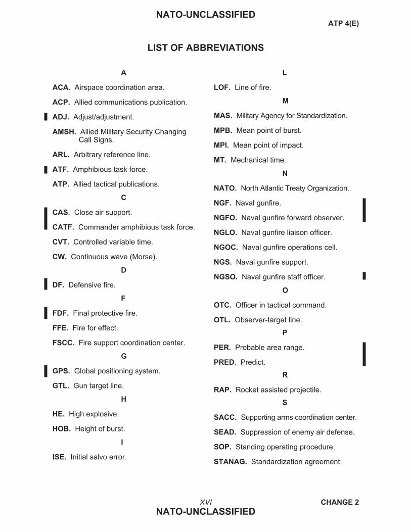
LIST OF ABBREVIATIONS
A
ACA. Airspace coordination area.
ACP. Allied communications publication.
ADJ. Adjust/adjustment.
AMSH. Allied Military Security ChangingCall Signs.
ARL. Arbitrary reference line.
ATF. Amphibious task force.
ATP. Allied tactical publications.
C
CAS. Close air support.
CATF. Commander amphibious task force.
CVT. Controlled variable time.
CW. Continuous wave (Morse).
D
DF. Defensive fire.
F
FDF. Final protective fire.
FFE. Fire for effect.
FSCC. Fire support coordination center.
G
GPS. Global positioning system.
GTL. Gun target line.
H
HE. High explosive.
HOB. Height of burst.
I
ISE. Initial salvo error.
L
LOF. Line of fire.
M
MAS. Military Agency for Standardization.
MPB. Mean point of burst.
MPI. Mean point of impact.
MT. Mechanical time.
N
NATO. North Atlantic Treaty Organization.
NGF. Naval gunfire.
NGFO. Naval gunfire forward observer.
NGLO. Naval gunfire liaison officer.
NGOC. Naval gunfire operations cell.
NGS. Naval gunfire support.
NGSO. Naval gunfire staff officer.
O
OTC. Officer in tactical command.
OTL. Observer-target line.
P
PER. Probable area range.
PRED. Predict.
R
RAP. Rocket assisted projectile.
S
SACC. Supporting arms coordination center.
SEAD. Suppression of enemy air defense.
SOP. Standing operating procedure.
STANAG. Standardization agreement.
XVI CHANGE 2
NATO-UNCLASSIFIED
NATO-UNCLASSIFIEDATP 4(E)

T
TOF. Time of flight.
TOT. Time on target.
U
UHF. Ultrahigh frequency.
V
VHF. Very high frequency.
VT. Variable time.
W
WP. White phosphorus.
XVII (Reverse Blank) CHANGE 2
NATO-UNCLASSIFIED
NATO-UNCLASSIFIEDATP 4(E)


PREFACE
0001 PURPOSE
This publication provides spotting proce-dures for NGS and supplementary information re-garding the conduct of NGS.
0002 SCOPE
This publication specifies mandatory spot-ting procedures for NGS in exact detail. Theseprocedures must be thoroughly understood andprecisely followed by ships, naval gunfire spotters,and supported units when conducting NGS in or-der to ensure maximum safety and effectiveness,even when the units involved have not been pre-viously associated or had an opportunity to con-duct prior liaison. Annex A provides examples ofthe specific procedures; remaining annexes pro-vide supplemental information; and the glossaryprovides precise definitions of naval gunfire spot-ting terms and of other terms associated withNGS.
0003 UNITS OF MEASUREMENT
altitude. Units of measurement are in meters,unless otherwise specified. Meters will beto an accuracy of the nearest 5 meters. (Ifaltitude is specified in feet, it will be to thenearest 20 feet.)
direction. Direction is the line about which thefall of shot is to be spotted. Units of mea-surement are in mils, measured from gridNorth unless otherwise specified. True ormagnetic North, or degrees, or other unitsmay be used, but the unit must be speci-fied. Mils will be sent to the nearest 10mils and degrees will be sent to the nearestdegree. Cardinal or intercardinal directionsmay be used (e.g., NORTH NORTH-WEST). If cardinal or intercardinal
direction is used, the accuracy of spottedrounds may be reduced.
distance. Units of measurement are in meters,unless otherwise specified. Note thatnearly all shipboard fire control equipmentis calibrated in yards. One yard equals0.914 meters.
grid location. Units of measurement are inmeters; grid location should be given to atleast the nearest 100 meters, but may begiven to the nearest 10 meters when addi-tional accuracy can be determined and isrequired.
height of burst. Units of measurement are inmeters, unless otherwise specified. HOB isgiven in increments of 5 meters.
shift. Units of measurement are in meters;shifts are measured as follows:
lateral shift — To the nearest 10 meters.
range shift — To the nearest 100 me-ters; to the nearest 50 meters when enteringFFE for point targets.
vertical shift — To the nearest 5 meters.
summit. Units of measurement are in metersfor a ground spotter; they must be in feetwhen the spotter is airborne.
time. Units of measurement for time are under-stood to be in seconds, unless otherwisespecified (e.g., Prime One, Prime Two,and Prime Three to indicate 15, 30, and45 seconds marks of any given minute).
XIX (Reverse Blank) CHANGE 4
NATO-UNCLASSIFIED
NATO-UNCLASSIFIEDATP 4(E)


CHAPTER 1
Spotting Procedures
SECTION I — PREFIRING
0101 REQUEST FOR SUPPORT
1. General. When a direct support ship isnot allocated, support must be requested as shownbelow.
2. Originator. When an NGS ship has notbeen allotted, a request for support may be origi-nated by:
a. Any unit or formation, with or withouta spotter.
b. Any spotter.
c. An aircraft that observes a suitabletarget.
d. The headquarters of the landing forcethat the naval force is supporting.
3. Passage of Requests. Requests forsupport are passed to the OTC through his NGSagency. The request will normally come from aground or air spotter or a landing force unit via thesupporting arms coordination agency. The proce-dure is explained in ATP 37.
4. Format of Request. Requests for sup-port must be transmitted in the following format.(Include new or modified target information asavailable.)
a. Target number, priority, classification.
b. Target location.
c. Target description.
d. Time and duration.
e. Ship/caliber requested.
f. Ordnance type required/requested.
g. Position of friendly troops.
h. Special instructions; e.g., airspace co-ordination, controlling agency, etc.
5. Allotment Signal. In response to a re-quest for support, the OTC orders allotment of asupport ship in the following format:
a. Target number.
b. (Ship’s call sign) report to (controllingagency call sign) on (net designator) at(time).
c. For mission to commence at (time).
d. Voice/code.
e. Estimated volume of fire required.
f. Ordnance type(s) required.
g. Allocated time period.
h. Special instructions; e.g., airspace co-ordination, unobserved fire, beacon infor-mation, etc.
6. Communication Procedures. Re-quests for NGS and ship allotment signals arecommunicated as described in Chapter 3.
0102 CALL FOR FIRE
1. General. A spotter’s call for fire is a con-cise request that contains the information needed bythe ship to fire on a target. The spotter transmits thecall for fire rapidly, but with sufficient clarity to en-sure that the request is understood, recorded, andread back without error by the ship’s radio operator.The spotter transmits the call for fire in two parts,with the break after the warning order and targetnumber; each part is read back.
2. Format of Call for Fire. Calls for firemust be transmitted in the following format:
1-1 CHANGE 2
NATO-UNCLASSIFIED
NATO-UNCLASSIFIEDATP 4(E)

a. Spotter identification.
b. Warning order and target number(Break).
c. Target location:
(1) By grid coordinates:
(a) Grid.
(b) Altitude.
(c) Direction (may be omitted ifmethod of control is not spotteradjust).
(2) By polar plot:
(a) Direction.
(b) Distance.
(c) Vertical shift (up/down).
(3) By a shift from a known point:
(a) Target number or referencepoint.
(b) Direction.
(c) Lateral shift (left/right).
(d) Range shift (add/drop).
(e) Vertical shift (up/down).
(4) By geodetic coordinates:
(a) Latitude and longitude.
(b) Altitude (meters).
(c) Direction (may be omitted ifmethod of control is not “Spotteradjust”).
d. Target description.
e. Method of engagement (as appropriate):
(1) Danger close.
(2) Trajectory.
(3) Ammunition.
(4) Armament.
(5) Number of guns.
(6) Number of salvos.
(7) Special instructions.
f. Method of control:
(1) “Fire for effect.”
(2) “Spotter adjust.”
(3) “Ship adjust.”
(4) (“At my command” may be usedas a modifier to the three methods ofcontrol.)
3. Spotter Identification. This is made inaccordance with ACP 124 and 125. The call signinitiates communication between the spotter andthe ship and informs any monitoring supportingarms coordinating agency which spotter is callingfor fire. The call signs effective for the operationare the ones used.
4. Warning Order and Target Number.“Fire mission” informs the ship that the trans-mission is a call for fire and clears the net for thetransmission. The spotter assigns a target numberfrom those allocated in the operation order. Thetarget number identifies the target for future refer-ence. Target numbers will consist of two lettersfollowed by four numbers (see Article 0218) (i.e.,NZ2045). After initial target number assignmentfor fresh, new, and simultaneous-engagement-of-two-target missions, the last two digits of thetarget number may be used to differentiate be-tween the targets.
5. Target Location. The spotter transmitsinformation that enables the ship to plot the loca-tion of the target. One of the following techniquesmust be used.
a. Grid Coordinates. The spotterpasses as accurate a grid coordinate aspossible for the target. The altitude of thetarget must be given. Direction is includedto provide a reference line for subsequentadjustments when required.
1-2 CHANGE 2
NATO-UNCLASSIFIED
NATO-UNCLASSIFIEDATP 4(E)

- EXAMPLE -
GRID 346729
ALTITUDE 35
DIRECTION 4200
or
GRID 35958876
ALTITUDE 55
DIRECTION 275° MAGNETIC
b. Polar Plot. The spotter locates thetarget with respect to his own location.The ship must know the spotter’s location.The spotter passes the direction to the tar-get, the distance, and the vertical shift. Ac-curate direction is critical. The verticalshift tells the ship how far the target’s lo-cation is above (up) or below (down) thespotter’s location.
-EXAMPLE-
DIRECTION 2160
DISTANCE 2400
DOWN 40
c. Shift From a Known Point. Theship must know the location and altitudeof the known point — a previously firedand recorded target, a planned target, or areference point selected by the spotter andpassed to the ship. To locate the target, thespotter provides the following information:
(1) From (reference point): The spot-ter identifies the known point.
(2) Direction: A spotting direction isidentified along which to apply the ele-ments of the shift.
(3) Lateral shift: How far left or rightthe target is from the known pointalong the spotting direction.
(4) Range shift: How much farther(add) or closer (drop) the target is fromthe known point along the spottingdirection.
(5) Vertical shift: How much the tar-get is above (up) or below (down) thealtitude of the known point.
-EXAMPLE-
FROM TARGET NUMBER AN1052
DIRECTION 5800
RIGHT 240
ADD 400
UP 35
d. Geodetic Coordinates. The spotter,using GPS receiver equipment, locates thetarget by degrees and minutes of latitudeand longitude as accurately as possible forthe target (North, South, East, and Westdescriptives are assumed to be understood).The altitude of the target must be given (inmeters). Direction is included for spotter-adjusted fire to provide a reference line forsubsequent adjustments when required.
-EXAMPLE-
LATITUDE 3429.433
LONGITUDE 07458.21
ALTITUDE 34
DIRECTION 275° TRUE
6. Target Description. The spotter mustaccurately describe the target in sufficient detailto provide tactical information to the monitoringsupporting arms coordinating agency. The descrip-tion may include:
a. What the target is (troops, equipment,trucks).
b. What the target is doing (digging in,attacking).
c. The number of elements (50 troops, 5trucks).
d. The degree of protection (in open, inbunkers).
e. The target’s size, shape, and attitude, ifsignificant (e.g., 200 X 500, attitude 2100).
NOTE
For target size and shape, meters arestandard and need not be specified.For target attitude, mils grid arestandard and need not be specified.
1-3 CHANGE 2
NATO-UNCLASSIFIED
NATO-UNCLASSIFIEDATP 4(E)

7. Method of Engagement. Naval gunfireis used primarily for destruction, suppression, orneutralization. This element provides informationon the method of engagement and special instruc-tions. When a subelement is not specified, thestandard is assumed. Figure 1-1 lists the standardelements of the call for fire.
a. “Danger Close.” The term, “Dangerclose,” is used when fire support is directedclose to friendly forces. Refer to paragraph0212.3 for further details. The spotter re-ports, “Danger close,” followed by a cardi-nal or intercardinal direction (based on gridNorth) and distance in meters from the tar-get to the nearest friendly troops.
-EXAMPLE-
DANGER CLOSE SOUTH SOUTH-
EAST 350
(1) First salvo intentions will alwaysbe specified by the spotter. The spotterwill request either first salvo offset(based on the spotting line or a cardinalor intercardinal direction):
-EXAMPLE-
DANGER CLOSE
SOUTHEAST 350
FIRST SALVO AT ADD 450
or
DANGER CLOSE SOUTH 350
FIRST SALVO AT NORTH 400
(2) Or first salvo at target:
-EXAMPLE-
DANGER CLOSE SOUTH SOUTH-
EAST 350
FIRST SALVO AT TARGET
(3) The responsibility for placementof the first salvo and all subsequentadjustments rests with the spotter andnot with the ship. The ship’s responsi-bility is to fire at the target as accu-rately and as quickly as possible.
b. Trajectory. The following applies toships capable of firing reduced charge or
high angle. The spotter or the ship mayrequire the ship to fire a higher than nor-mal trajectory for targets in defilade, or toincrease accuracy on targets without a ver-tical face; and can also be used to fire overan airspace, etc. This can be accomplishedby either requesting “Reduced charge” or“High angle.” If this subelement is omit-ted, the ship fires a normal trajectory.
(1) “Reduced Charge” and “Can-cel Reduced Charge.” By request-ing reduced charge at shorter ranges, thespotter increases the angle of fall of therounds, which is more effective againsttargets in defilade. In addition, reducedcharge lowers the initial velocity of theprojectile. This prevents ripped para-chutes on illumination rounds at shorterranges. If reduced charge becomes nec-essary during a mission, the ship orspotter specifies a change in trajectoryby ordering “Reduced charge.” The shipor spotter orders “Cancel reduced charge”when it is no longer required or available.
(2) “High Angle” and “CancelHigh Angle.” High-angle fire with afull charge is used to engage targets indefilade when extended range or otherconsiderations prevent the use of re-duced charge. If a target in defilademust be engaged, and the ship cannotfire reduced charge, the ship or spotterorders “High angle.” The ship or spot-ter orders “Cancel high angle” when itis no longer required.
1-4 CHANGE 2
NATO-UNCLASSIFIED
NATO-UNCLASSIFIEDATP 4(E)
METHOD OF ENGAGEMENT
Danger Close:
Trajectory:
Ammunition:
Armament:
No. of Guns:
No. of Salvos:
Special Instructions:
Not danger close
Full charge/normal angle
HE/quick
Main
One
One
None
METHOD OF CONTROL
Spotter Adjust
Figure 1-1. Standard Elements of theCall for Fire

c. Ammunition. The spotter selects themost appropriate ammunition for the ad-justment and FFE phases of the mission.The type of ammunition in each phase isspecified by passing the type of ammuni-tion followed by “in adjustment” or “in ef-fect.” If the phase is not specified, the shipwill fire the specified ammunition duringboth the adjustment and FFE phases.
(1) Projectile. Shell HE will be usedduring both the adjustment and FFEphases, if the type of projectile is notspecified. If the spotter wants the shipto fire a different type of shell duringeither phase, he must request it.
-EXAMPLE-
SHELL WP (in adjustment and effectunderstood)
(2) Fuze. Unless otherwise speci-fied, the ship will fire fuze quick inboth adjustment and FFE, for all pro-jectiles but illumination and armorpiercing. When firing shell illumina-tion, the fuze is understood to be time.When firing shell armor piercing, thefuze is understood to be delay.
-EXAMPLE-
FUZE CVT IN EFFECT (fuze quick inadjustment understood)
d. Armament. If the firing ship isarmed with 5-inch and larger caliber guns,the spotter may designate which battery hedesires the ship to fire. “Main armament”designates the ship’s largest guns; “Sec-ondary armament,” the smaller guns. Ifthis element is not sent, it will be assumedby the ship that the spotter wants the mainarmament.
e. Number of Guns. The number ofguns requested for adjustment and/or FFEwill be assumed to be one gun unless oth-erwise specified by the spotter in the callfor fire. One gun is standard and need notbe specified.
f. Number of Salvos. The spotter statesthe volume of fire he desires when he uses
“Fire for effect” as the method of control.If the spotter uses “Spotter adjust,” heomits this information from the call forfire, until after he has adjusted rounds ontothe target, at which point he will state thenumber of salvos, prior to FFE.
g. Special Instructions. The spotterinforms the ship when he desires the use ofspecific, nonstandard techniques. Specialinstructions are provided in Figure 1-2. Seealso Figure 1-1 for the standard elements ofthe call for fire.
h. Time on Target. A specific techniqueof controlling fire is time on target, whichcan be expressed as a time on a synchro-nized clock, or be based on an elapsedtime or identifiable event.
(1) Synchronized Clock. Thesynchronized clock uses commontime based on either a local or the uni-versal (ZULU) time zone establishedby the senior headquarters. This tech-nique requires periodic time checks.Once established, the synchronizedclock is the preferred technique of coor-dinating the timing of fires. See Figure1-2 for an example of this technique.
(2) Elapsed Time. Time on targetmay be coordinated by specifying anumber of minutes and seconds toelapse from a stated countdown refer-ence. Elapsed time is best used whentiming the delivery of fires in animmediate or time-critical situation,when a synchronized clock has notbeen established, or when a synchro-nized clock’s accuracy is doubtful.Elapsed time is expressed in relationto the transmission of a “Hack”. TheHack is transmitted by specifying thenumber of minutes and seconds toelapse before the specified event is tooccur (e.g., ordnance impact on target).To avoid confusion, the word, “Hack” isonly used in transmission to initiate oracknowledge the Hack. See Figure 1-2for an example of this technique.
(3) Event. Fires may be timed in re-lation to a specific, identifiable event(e.g., H-hour).
1-5 CHANGE 2
NATO-UNCLASSIFIED
NATO-UNCLASSIFIEDATP 4(E)
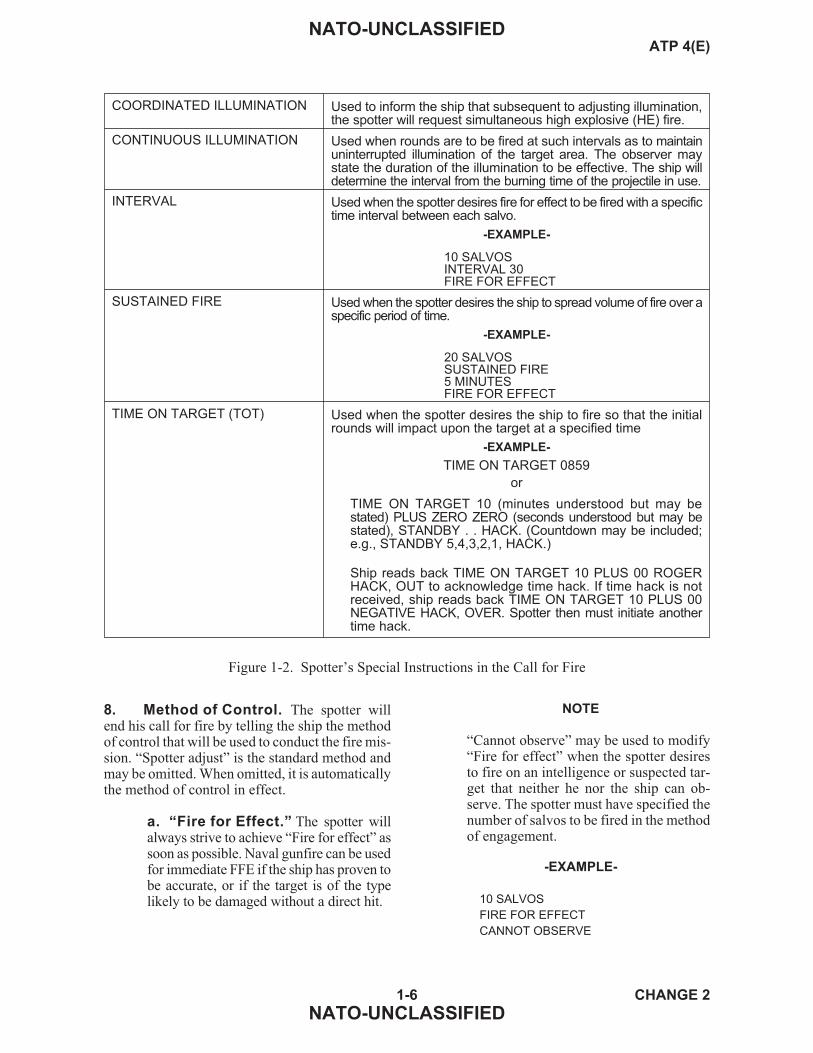
8. Method of Control. The spotter willend his call for fire by telling the ship the methodof control that will be used to conduct the fire mis-sion. “Spotter adjust” is the standard method andmay be omitted. When omitted, it is automaticallythe method of control in effect.
a. “Fire for Effect.” The spotter willalways strive to achieve “Fire for effect” assoon as possible. Naval gunfire can be usedfor immediate FFE if the ship has proven tobe accurate, or if the target is of the typelikely to be damaged without a direct hit.
NOTE
“Cannot observe” may be used to modify“Fire for effect” when the spotter desiresto fire on an intelligence or suspected tar-get that neither he nor the ship can ob-serve. The spotter must have specified thenumber of salvos to be fired in the methodof engagement.
-EXAMPLE-
10 SALVOS
FIRE FOR EFFECT
CANNOT OBSERVE
1-6 CHANGE 2
NATO-UNCLASSIFIED
NATO-UNCLASSIFIEDATP 4(E)
COORDINATED ILLUMINATION Used to inform the ship that subsequent to adjusting illumination,the spotter will request simultaneous high explosive (HE) fire.
CONTINUOUS ILLUMINATION Used when rounds are to be fired at such intervals as to maintainuninterrupted illumination of the target area. The observer maystate the duration of the illumination to be effective. The ship willdetermine the interval from the burning time of the projectile in use.
INTERVAL Used when the spotter desires fire for effect to be fired with a specifictime interval between each salvo.
-EXAMPLE-
10 SALVOSINTERVAL 30FIRE FOR EFFECT
SUSTAINED FIRE Used when the spotter desires the ship to spread volume of fire over aspecific period of time.
-EXAMPLE-
20 SALVOSSUSTAINED FIRE5 MINUTESFIRE FOR EFFECT
TIME ON TARGET (TOT) Used when the spotter desires the ship to fire so that the initialrounds will impact upon the target at a specified time
-EXAMPLE-
TIME ON TARGET 0859
or
TIME ON TARGET 10 (minutes understood but may bestated) PLUS ZERO ZERO (seconds understood but may bestated), STANDBY . . HACK. (Countdown may be included;e.g., STANDBY 5,4,3,2,1, HACK.)
Ship reads back TIME ON TARGET 10 PLUS 00 ROGERHACK, OUT to acknowledge time hack. If time hack is notreceived, ship reads back TIME ON TARGET 10 PLUS 00NEGATIVE HACK, OVER. Spotter then must initiate anothertime hack.
Figure 1-2. Spotter’s Special Instructions in the Call for Fire

b. “Spotter Adjust.” The spotter ap-plies this method of control when he feelsthat he must adjust fire onto the target, dueto questionable target location or firing in-accuracy. It may also be ordered by thespotter when he wishes to revert to adjust-ment at any time during a mission.
c. “Ship Adjust.” The spotter may sug-gest that the ship adjust fire onto the target,when the target is visible to the ship. Thismethod utilizes the accurate direct fire con-trol system aboard many ships. The observermay provide range observations along the
GTL. The ship will provide a normal pre-firing report (see Article 0103) before be-ginning the engagement to assist the spot-ters in providing these range observations.
NOTE
“At my command” is a modifier tothe method of control and may beused when the spotter wishes to con-trol the precise firing of each salvo inthe “Spotter adjust,” “Ship adjust,”and the commencement of firing in“Fire for effect.”
SECTION II — OPENING FIRE
0103 PREFIRING REPORT
1. The gunfire support ship makes the fol-lowing report to the spotter prior to firing upon thetarget designated in the call for fire. The messageconsists of the following information.
a. Gun-Target Line. The ship reportsthe GTL to the spotter, using the sameNorth reference and units as the spotterused in the call for fire. Subsequentchanges of 200 mils (10°) will also be re-ported to the spotter. If the direction isGTL, this tolerance changes to 100 mils(5°) to facilitate more accurate spotting. Ifthe direction in the call for fire was a cardi-nal or intercardinal direction, a GTL, or if itwas omitted, the ship will use mils grid.
-EXAMPLE-
GUN-TARGET LINE 2740
or
GUN-TARGET LINE 170° MAGNETIC
NOTE
Mils grid is the assumed unit of mea-surement for GTL and may be omit-ted from the report. All other units ofmeasurement (i.e., mils magnetic,degrees magnetic, etc.) will be in-cluded in the report.
b. “Ready.” The ship reports “Ready,”followed by the time of flight in seconds,when she is ready to fire the first salvo ofthe mission and is awaiting the spotter’s
order to fire. The ship transmits “Ready,”without the time of flight before subsequentsalvos, only:
(1) If “At my command” has beenordered by the spotter and time offlight has not changed by more than 5seconds.
(2) To end a “Delay” by the ship.
(3) To indicate that a “Check solu-tion” has been accomplished.
c. Time of Flight. The ship will imme-diately report time of flight when the timeof flight changes by more than 5 seconds.
d. “First Salvo at (Point of Aim).”The ship reports this element when thespotter has included “Danger close” in thecall for fire. It confirms the point of aimordered by the spotter.
e. Summit. The ship reports the summitto indicate the highest altitude above meansea level that the projectile will reach in itsflight to the target.
(1) Summit, in feet, always must bereported when the spotter is airborne.
(2) When requested by a ground spot-ter, summit is reported in meters.
1-7 CHANGE 2
NATO-UNCLASSIFIED
NATO-UNCLASSIFIEDATP 4(E)
(3) A subsequent change of 300 feetfor airborne spotter or 100 meters forground spotter will be reported to thespotter.
f. Changes. If the ship intends to changeany element of the spotter’s call for fire,she must report the change to the spotter.
0104 ORDER TO FIRE
1. The spotter must give the specific orderto fire, when in control, before the first salvo isfired. Thereafter, unless the “At my command”procedure is in force, an adjustment correction,“Repeat,” “Fire for effect,” or “Cancel check fir-ing” is the executing order to fire.
0105 REPORTS ON OPENING FIRE
1. The ship transmits the following reportsto the spotter every time a salvo is fired, until“Fire for effect,” at which time she passes the re-ports for the first salvo only. These reports are notread back by the spotter.
a. “Shot.” “Shot” is transmitted at themoment of firing a salvo.
b. “Splash.” “Splash” is transmitted 5seconds before a salvo is due to detonate.“Splash” is not reported during FFE whentwo or more ships are conducting a massed-fire mission, during rotation missions, or forstar shells after the beginning of the HEadjustment phase of coordinated illumina-tion missions.
SECTION III — FIRING
0106 FIRING REPORTS AND ORDERS
1. Procedure for Initiating SubsequentCorrections. After the initial burst, the spottertransmits corrections until the fire mission is com-pleted. Corrections include appropriate changes inelements of the call for fire previously transmittedand the necessary adjustment corrections for devi-ation, range, and HOB. On completion of adjust-ment, it is advisable for the spotter to check theMPI of additional guns to be used in FFE by order-ing “(Number) guns, one salvo.” Elements maythen require further correction. The sequence inwhich the spotter orders corrections is as follows:
a. Direction of spotting line.
b. “Danger close” or “Cancel dangerclose.”
c. “Trajectory.”
d. Ammunition.
e. Deviation.
f. Range.
g. HOB.
h. Number of guns.
i. Number of salvos.
j. Method of control.
NOTE
Any element for which a change orcorrection is not desired is omitted.
2. Procedures for Corrections.
a. Direction of Spotting Line. Achange in the direction of the spotting linecan be made whenever the spotter wishes,but should be made if his directionchanges by 100 mils (5°) or more. Thespotter must provide the direction of thespotting line if he had fired for effect im-mediately using grid coordinates (with thedirection omitted) and has subsequentlydecided to adjust the impact of the rounds.
b. “Danger Close” or “CancelDanger Close.” Ships will not enter into“Danger close” procedures unless specifi-cally requested by the spotter or a coordi-nating agency. The spotter orders “Canceldanger close,” if “Danger close” was in-cluded in the call for fire and the target isno longer within the range for “Dangerclose.”
1-8 CHANGE 2
NATO-UNCLASSIFIED
NATO-UNCLASSIFIEDATP 4(E)

c. Trajectory. The ship or spotter speci-fies a change in trajectory by ordering“Reduced charge.” The ship or spotter or-ders “Cancel reduced charge” when it isno longer required. If it becomes neces-sary to engage a target in defilade and theship cannot use reduced charge, the shipor spotter may order “High angle.” Theship or spotter orders “Cancel high angle”when it is no longer required.
d. Ammunition. When the spotter de-sires to change the type of ammunition, ei-ther the projectile or the fuze, he orders thedesired change.
e. Deviation. When the round lands leftor right of the spotting line, the spotter de-termines the correction desired to bringthe burst onto the spotting line. Deviationcorrections are transmitted as “Right/left(amount)” in increments of 10 meters.This element is omitted when there is nocorrection for deviation.
f. Range. When the round lands short orbeyond the target on the spotting line,range corrections are transmitted as“Add/drop (amount)” in increments of100 meters. When firing for effect, an addor drop of 50 meters can be sent to im-prove accuracy. This element is omittedwhen there is no correction for range.
g. Height of Burst. HOB correctionscan be made in two contexts — to adjustground bursts in very steep terrain and toadjust airbursts or illumination height.When adjusting ground bursts in steep ter-rain, it should be remembered that an up ordown correction will have a range effecton the GTL depending on the terrain. Thecorrections made for airbursts will dependon the terrain and the type of fuze beingfired. HOB for illumination will be madein increments/multiples of 50 meters.
h. Number of Guns. When the spotterdesires to change the number of guns, ei-ther in adjustment or in effect, he ordersthe desired change.
i. Number of Salvos. When the spotterdesires to change the number of salvos,
either in adjustment or in effect, he ordersthe desired change.
j. Method of Control. When the spotterdesires to change the method of control,he transmits the desired method of control(see paragraph 0102.8).
3. “Repeat.” This is an order to repeat themethod of engagement without change to MPI orvolume of fire. If a correction to the MPI is re-quired, it prefixes “Repeat.”
-EXAMPLE-
ADD 100
REPEAT
NOTE
During adjustment, “Repeat” is un-derstood and not stated when thespotter’s transmission includes devi-ation, range, or HOB corrections.
4. Other Spotter’s Firing Reports andOrders. Other firing reports and orders that aspotter may use during a fire mission are providedas follows.
a. “Check Firing” or “Cancel CheckFiring.” “Check firing” interrupts firingtemporarily, usually for safety reasons.“Cancel check firing” can only be givenby the originator of “Check firing.” If themission is “At my command,” or if after“Check firing, check solution,” the sup-port ship should report “Ready” to thespotter after reporting either “Neglect” or“Solution correct.” On the command“Cancel check firing, fire” the ship willfire. When more than one firing ship is onthe same radio net, “Check firing” ap-plies to all firing ships until “Cancelcheck firing” is sent by the originator.
b. “Check Solution.” (Always pre-ceded by “Check firing.”) “Check solu-tion” requests the ship to check her firecontrol solution.
(1) It should be used when the spotterobserves an obvious error in the fall ofshot:
1-9 CHANGE 3
NATO-UNCLASSIFIED
NATO-UNCLASSIFIEDATP 4(E)

(a) In the initial salvo.
(b) From salvo to salvo.
(2) When the ship has completed thecheck, she reports “Solution correct/neglect,” whichever the case may be,and then “Ready” to indicate she isready to fire again.
c. “Lost.” Reported during adjustment,when the fall of shot is not observed. Thespotter also commands a remedial action.
-EXAMPLE-
LOST, REPEAT, OVER
or
LOST, DROP 400, OVER (from
a speculated burst point).
d. “Record as Target.” Ordered at thecompletion of FFE and before transmis-sion of “End of mission.” “Record as tar-get” requests the ship to retain the plot ofthe location of the target for future refiringor for use as a reference point. Targetsmust be stored by the ship for as long asthe spotter requires and may only beerased by the order, “Cancel targetnumber . . . ”
-EXAMPLE-
FIRE MISSION
TARGET NUMBER XJ4567
. . . . .
RECORD AS TARGET
END OF MISSION
FIRE MISSION
REFIRE XJ4567
10 SALVOS FIRE FOR EFFECT
. . . . .
END OF MISSION
CANCEL TARGET NUMBER XJ4567
e. “Spreading Fire.” Reported uponcompletion of the initial FFE when thespotter desires to distribute FFE over alarge area by repeated FFE combined withdeviation and range corrections. “Spread-ing fire” is not required for each subse-quent correction during the followingFFE.
-EXAMPLE-
SPREADING FIRE
RIGHT 100
ADD 200
REPEAT
OVER
f. “Straddle.” Can be reported when amultigun/multisalvo adjustment bracketsthe target. “Straddle” will be sent duringMPI ship-adjust missions.
g. “Trend.” Reported as “Trend (direc-tion and distance)” when the spotter ob-serves that rounds are moving away fromthe target. If the trend is noticed in the FFEand there are enough salvos remaining, acorrection can be sent to put the remainingsalvos back into the target. Trend may beused with “Check solution.”
-EXAMPLE-
TREND SOUTHWEST 100 PER SALVO
h. “Fresh Target.” At any time duringa fire mission, the spotter may desire toshift his fire from the original target to atarget of higher priority. The spotter willdo so by transmitting a correction from thelast impacted salvo. The ship interruptsengagement of the original target in orderto engage the fresh target.
(1) The call for fire begins with“Fresh target,” followed by the fol-lowing information:
(a) Target number.
(b) Deviation correction.
(c) Range correction.
(d) Elevation correction.
(e) Target description.
(f) Method of engagement (ifchanged from original target).
(g) Method of control (if changedfrom original target).
1-10 CHANGE 3
NATO-UNCLASSIFIED
NATO-UNCLASSIFIEDATP 4(E)

(2) Fresh-target procedures can beutilized with all fire control systems.
(3) The spotter may transmit a newdirection for the spotting line after theship fires the initial salvo on the freshtarget, only if the new direction differsfrom the old by more than 100 mils or5°.
(4) Only those elements of thefresh-target method of engagementand method of control that changefrom the original target (shell, fuze,etc.) will be transmitted.
(5) In order to reengage the originaltarget or another target, the spottermay again initiate fresh-target proce-dures. The spotter must not transmit“End of mission” until all desired tar-gets have been engaged. Mission ter-minations will be transmitted in targetnumber sequence. They must includethe complete target number.
-EXAMPLE-
END OF MISSION
TARGET NUMBER AF0013
TROOPS DISPERSED
TARGET NUMBER AF0014
TARGET NEUTRALIZED
OVER
i. “New Target.” At any time during afire mission a spotter may wish to engageanother target that is not necessarily of ahigher priority. If the ship has the capabil-ity, the spotter can do this simultaneouslywithout ceasing fire on his original target.This “Twin target” procedure can be usedto speed adjustment for future fireplansfor the simultaneous engagement of twotargets when only one fire unit is avail-able. Target is indicated using any of thethree standard methods of target location:
(1) Call for fire on the second targetbegins with “New target” and is fol-lowed by the other standard elementsof the call for fire sent in one transmis-sion. It is sent following acknowledg-ment of initial target data or after areport of “Shot.”
(2) New target procedures can only beused with ships that have fire controlsystems that are capable of computingtwo firing solutions simultaneously.
(3) A new direction is sent if re-quired, and adjustment is conducted asfor standard fire mission.
(4) To avoid confusion spotter andship must preface all transmissionswith the target number to which ordersor responses apply. (This may be ab-breviated to the last two digits of thetarget number when this will not causeconfusion and will reduce transmis-sion time.) Once engagement of onetarget is complete target number pre-fixes may be dropped.
-EXAMPLE-
TARGET 09 ADD 400
TARGET 10 LEFT 100 ADD 200
OVER
(5) Upon completion of fire for effecton either mission, the spotter may or-der “End of mission.” If he requires torecord a target he must order this priorto transmitting “End of Mission.”
-EXAMPLE-
TARGET 09
RECORD AS TARGET AB 2009
END OF MISSION
5 VEHICLES BURNING
(FIRE MISSION ON TARGET 10
CONTINUES TO FIRE FOR EFFECT.)
END OF MISSION
BUILDINGS DESTROYED
OVER
5. Ship’s Reports and Orders.
a. “Delay.” “Delay” indicates that theship is not ready to fire. It is normally fol-lowed by the estimated time (in minutes)when the ship will be ready to fire (e.g.,DELAY 05). If the cause is known and thesituation permits, a reason for the delaymay be sent using the November Code (See
1-11 CHANGE 2
NATO-UNCLASSIFIED
NATO-UNCLASSIFIEDATP 4(E)

so that the spotter is better able to appreci-ate the situation. The ship transmits“Ready” when she is prepared to fire.
b. “Neglect.” “Neglect” informs thespotter that the last round was fired withincorrect firing data. The ship transmits“Ready” to indicate that the situation iscorrected.
c. “Rounds Complete.” The shiptransmits “Rounds complete” when allsalvos requested in FFE have been fired.
d. Direction of Gun-Target Line. Theship informs the spotter whenever there isa subsequent change of the GTL of morethan 10° (200 mils). If the spotter’s direc-tion is GTL, this tolerance is 5° (100 mils).
-EXAMPLE-
GUN TARGET LINE
156 DEGREES GRID
OVER
e. Time of Flight. The ship informs thespotter whenever there is a subsequentchange in time of flight of more than 5seconds.
f. Summit. The ship informs the spotterwhenever there is a subsequent change insummit of 300 feet (air spotter) or 100 me-ters (ground spotter). The summit report isonly required when working with an airspotter or when requested by the groundspotter.
SECTION IV — TERMINATION OF FIRE
0107 TERMINATION BY SPOTTER
1. A spotter may end a fire mission at anytime. The mission is normally terminated after theFFE phase. When the spotter is satisfied that de-sired results have been achieved, he orders “Endof mission” and reports results.
-EXAMPLE-
END OF MISSION
20 CASUALTIES
OVER
2. When fresh-target procedure is used toengage multiple targets during one fire mission,the spotter reports each target.
-EXAMPLE-
END OF MISSION
TARGET NUMBER ZJ1076
AUTOMATIC WEAPON SILENCED
TARGET NUMBER ZJ1077
40 CASUALTIES
OVER
0108 TERMINATION BY SHIP
1. The commanding officer of the gunfiresupport ship may determine that he has to termi-nate fire on a mission. The most likely reasons forthis are:
a. The target is out of range.
b. The ship has run short of ammunition.
c. There is a crest clearance problem.
d. The ship comes under threat.
2. When the ship is unable to fire, it reports“Will not fire” to the spotter. In every case, the shipprovides the spotter with the reason for not firing,if transmission of this information will not harmfriendly forces.
1-12 CHANGE 2
NATO-UNCLASSIFIED
NATO-UNCLASSIFIEDATP 4(E)

SECTION V — CORRECTION OF ERRORS
0109 CORRECTING ERRORS INTRANSMISSION
1. Errors are sometimes made in transmit-ting data by the spotter or the ship. When thesender realizes that he has made an error, he an-nounces “Correction” and transmits the correctdata:
CORRECTION
DIRECTION 5680
OVER
2. The correction is made as an interruptionin the transmission, and the transmission will con-tinue with the last word correctly transmitted.
3. When an error has been made in a sub-element and correction of the subelement will af-fect the transmitted data, the sender announces“Correction” and retransmits the correctedsubelement and all affected data in proper se-quence. The word, “Correction,” is then read backalong with the corrected version. For example, thespotter has transmitted:
LEFT 200
ADD 400
UP 40
OVER
4. He realizes that this was in error, andsends:
CORRECTION
LEFT 200
DROP 400
UP 40
OVER
5. If the spotter omitted “Left 200” and “Up40” from the corrected transmission, the shipmight not include them. The omission would atleast add confusion.
6. When an error has been made in asubelement of a shift-from-a-known-point targetlocation, the entire shift-from-a-known-point tar-get location must be repeated.
7. The proword, “Wrong,” is used in radio-telephone procedure. Its use is modified in calls forfire. An error noted during readback is correctedby the word, “Wrong,” followed by the correctversion. The word, “Wrong,” is then readback,along with the read back of the corrected version.
1-13 (Reverse Blank) CHANGE 2
NATO-UNCLASSIFIED
NATO-UNCLASSIFIEDATP 4(E)

CHAPTER 2
Conduct of Fire
SECTION I — GENERAL
0201 METHODS OF CONTROL
1. General. The spotter has the choice ofthree methods of control of fire; he also has theoption of modifying those methods of controlwith the use of either “At my command” or, in thecase of FFE, “Cannot observe.” He informs thefiring ship which control method will apply andmay change the method of control at any time hedeems advisable. The firing ship may initiate di-rect fire, with the spotter’s concurrence, by suggest-ing “Ship adjust,” whenever the target indicatedby the spotter is identified positively and is visiblefrom the ship.
2. “Fire for Effect.” The spotter’s primaryconcern is to place accurate fire upon targets. Be-cause surprise fire is much more effective, thespotter requests “Fire for effect” in his initial callfor fire, if he can accurately locate the target. If thespotter cannot observe the target but has an accu-rate target location, FFE is an appropriate tech-nique for attacking the target. When the spotterrequests “Fire for effect,” he must also inform theship of the volume of fire required. (“Cannot ob-serve” can be used as a modifier with “Fire for ef-fect” when the target is of high enough priority towarrant being fired upon with no one observingthe fall of shot to ensure the results desired areobtained.)
3. “Spotter Adjust.” This is the primarymethod of control. This method of control is stan-dard. When used, it may be omitted from the callfor fire. The spotter is responsible for adjustment(i.e., ordering corrections relative to the spottingline). The ship converts spotting line corrections toGTL corrections, which it applies to the armament.
4. “Ship Adjust.” The ship or the spottermay suggest the “Ship adjust” method of control,if either considers that the ship is in a better posi-tion to spot. The spotter designates the target inthe normal manner, but the ship spots and adjustsits own fire. The spotter should assist the ship, ifpossible, by providing GTL range observations,
because the ship may experience difficulty inadjusting for range.
5. Modifiers to the Method of Control.The following can be used as modifiers to the var-ious methods of control as the spotter feels arenecessary.
a. “Cannot Observe.” When the spot-ter desires to fire on a known or suspectedtarget that neither he nor the ship can ob-serve, he uses “Cannot observe” as amodifier to the method of control. Theonly logical method of control in this situ-ation is FFE. The spotter must specify thenumber of salvos to be fired.
b. “At My Command.” When the spot-ter desires to control the firing of eachadjusting salvo and the first salvo of hisFFE, he should specify “At my command.”When the ship is ready to fire, the ship willreport “Ready” and the spotter will thentell the ship “Fire.”
0202 SELECTION OF SPOTTING LINE
1. General. The spotter selects a referenceline on the ground on which the fall of shot can bespotted during a “Spotter adjust” method of controlmission, or a target can be located using ashift-from-a-known-point or polar-plot method. Theazimuth of the spotting line, known as “direction,”is selected for ease of spotting and is transmitted tothe ship. It may be any of the following lines.
2. Observer-Target Line. The directionfrom the spotter to the target, known as the OTL,is the direction most commonly used by groundspotters to spot naval gunfire. The OTL is the di-rection most easily and accurately measured andis normally the line along which spotting can bemost accurately accomplished. The spotter maydetermine the direction by using a compass, usinga map and protractor, measuring away from aknown direction on the ground, or by estimate.
2-1 CHANGE 2
NATO-UNCLASSIFIED
NATO-UNCLASSIFIEDATP 4(E)

3. Gun-Target Line. The direction fromthe gun to the target is known as the GTL. Aground spotter can visualize the GTL if he knowsthe ship’s location. He may find it a useful direc-tion if he is positioned on or near the GTL. TheGTL is the spotting line most commonly used byaerial observers.
4. Arbitrary Reference Line. In terrainwith prominent features, a spotter may select andorder the direction of a fixed reference line on theground, which passes through the target and oneor more of the prominent features. Or, where a tar-get is situated close to a straight feature, such asrailroad tracks, it may be convenient to visualize aline on the ground that runs through the target andis parallel to the railroad tracks. An ARL may beused in tactical situations in which transmissionof the OTL may compromise the spotter’slocation.
5. Cardinal/Intercardinal Direction. Thespotter may use a cardinal/intercardinal directionas a spotting line.
6. Direction. The use of the OTL for direc-tion simplifies spotting procedures for the groundspotter, but there is a chance of compromising thespotter’s location. The use of a terrain referenceline for direction will not compromise the spotter’slocation. The use of the observer-reference pointline will not compromise the spotter’s location andwill not change during the engagement. Neverthe-less, the use of this line could be more difficult forthe spotter. The use of the GTL by the spotter sim-plifies procedures for the ship but may be difficultfor the spotter to reconcile with the terrain. TheGTL will also be continuously changing with theship’s movement. To use the GTL, the spotter or-ders “Direction gun-target line.” The ship will re-port the current direction of the GTL to the spotterin the prefiring report. When GTL is used as thespotting line, the ship should report any changes of5° (100 mils) or more to the spotter.
0203 SPOTTING
1. General. A spotting is the spotter’s de-termination of the location of a shell’s burst withrespect to the target, as observed along the OTL.Spottings are made for deviation (in mils), forrange, and, in fuze time fire, for HOB (in mils).The spotter must make his observations at the in-
stant of the burst, in the order that presents the mostdifficulty in spotting. The correct sequence for ac-curacy of spotting is:
a. HOB (to the nearest 1 mil that the burstis above the target).
b. Range (over or short).
c. Deviation (to the nearest 5 mils left orright).
2. HOB Spotting. HOB spotting terms are:
a. “Air” — A round or a group of roundsthat bursts in the air is spotted as, “Air (somany mils above the target)” (e.g., AIR 15).
b. “Graze” — A round or a group ofrounds that bursts on impact is spotted as“Graze.”
c. “Mixed (preponderance)” — Whensome rounds burst in the air and some onimpact, the spotting is “Mixed (prepon-derance).” For example, in a 10-salvoFFE, if 8 salvos burst in the air and 2 sal-vos burst upon impact, the spotting is“Mixed air.”
d. “Special Situations” — The terms“High” or “Low” may be used to spot animpact on a vertical face. When a roundimpacts below the target on a verticalface, it is spotted as “Low.” In this situa-tion the spotter should use “Up” or“Down” corrections when adjusting toa target using the standard HE/quick,shell/fuze combinations.
3. Range Spotting. Normally, a roundthat bursts on or near the OTL will provide a defi-nite range spotting. Figure 2-1 provides a guidefor the approximate areas for range spottings anda list of the spotting terms used in accordance withthe guide.
4. Deviation Spotting. The spotter ob-serves the angular amount and direction of the de-viation of the location of the burst as seen from hisposition. The spotter measures the deviation (inmils) with binoculars or some other means. Thespotting terms are:
2-2 CHANGE 2
NATO-UNCLASSIFIED
NATO-UNCLASSIFIEDATP 4(E)

a. “Line” — The burst is on the spottingline.
b. “(So many mils) right (left)” (e.g., 16LEFT).
0204 ADJUSTMENT
1. Direction. The spotter normally uses theOTL as the direction. Therefore, his observationsof bursts are translated into corrections using acommon reference line. The spotter must bear inmind that when the OTL and the direction are dif-ferent, then his observations and subsequent cor-rections must be reconciled. For example, whenthe OTL and direction are at right angles to eachother, left/right observations must be converted toadd/drop corrections.
2. Corrections. After the spotter has madehis spotting determination, he sends corrections(in meters) to the ship to move the next burst in re-lation to the direction or spotting line. The spotterpasses corrections to the ship in the reverse of theorder used in spottings:
� Deviation (to the nearest 10meters).
� Range.
� HOB (to the nearest 5 meters).
a. Deviation Corrections. Correctionsare made as follows:
(1) The distance (in meters) that theburst is to be moved is determined bymultiplying two amounts:
(a) The spotting deviation (inmils).
(b) The OT factor (distance (inmeters) between the spotter andthe target, divided by 1,000).
(2) Deviation corrections are made tothe nearest 10 meters.
(3) A deviation correction of less than30 meters is considered minor and willbe ignored during fire missions onarea targets.
(4) When the spotter’s OTL is per-pendicular to the GTL, the spottershould consider the large range dis-persion when making a deviationcorrection.
b. Range Corrections. The spotterhas three methods for making rangecorrections:
� Bracketing.
� Creeping.
� One-round adjustment.
(1) Bracketing. The spotter estab-lishes a range bracket as early in theadjustment phase as possible, oncehe has made the first definite rangespotting.
(a) The first range correctionshould result in the next salvobeing spotted opposite the spot-ting of the previous salvo. For
2-3 CHANGE 2
NATO-UNCLASSIFIED
NATO-UNCLASSIFIEDATP 4(E)
DIRECTION OF TARGET
RANGE SPOTTING TERMS
1. “Over” — A burst that appears to be beyond thetarget.
2. “Short” — A burst that appears to be short of thetarget.
3. “Target” — The impact of the burst has effect onthe target.
4. “Range Correct” — A burst that appears to havethe correct range.
5. “Doubtful” — A burst whose range cannot bedetermined,usuallywhentheburst isanexcessivedistance right or left of the target.
6. “Lost” — A burst whose location cannot bedetermined.
Figure 2-1. Approximate Areas and Terms forVarious Range Spottings
DOUBTFUL DOUBTFULRANGE
CORRECTRANGE
CORRECT
OVER
SHORT
T

example, if the first definite rangespotting is “Short,” the spotteradds an amount sufficient to ob-tain a spotting of “Over” on thenext salvo.
(b) Subsequent range correc-tions are cut in half to move eachround successively closer to thetarget.
(c) Range corrections are madein even multiples of 100 meters(i.e., 800, 400, 200, and 100 me-ters) to facilitate establishing andsplitting of range brackets.
(d) Once a range bracket is es-tablished, the spotter splits eachrange bracket until FFE is appro-priate. The spotter must exercisegood judgment throughout theadjustment phase, rather than au-tomatically splitting the bracket.For example, the spotter adds 800meters after an initial range spot-ting of “Short.” The second rangespotting is “Over,” but the burstis much closer to the target thanthe initial burst. A range correc-tion of “Drop 200,” rather than“Drop 400,” would be appropri-ate. The spotter must be aggres-sive in the conduct of adjustmentand use every opportunity toshorten the adjustment phase.
(2) Creeping. The spotter orderscorrections towards the target, ensur-ing that these corrections for devia-tion and/or range do not endangerfriendly forces. The combined effectof each correction should not exceed200 meters when adjusting a “Dangerclose” mission. The terrain around thetarget will dictate the use of creepingfire. If the target being engaged is lo-cated on the military crest, and brack-eting or a HOB adjustment may causethe next impact to fall “lost,” then thecreeping method may be used. In thissituation, the creeping method will al-low the spotter a view of all impactsand result in a timely FFE. Creepingmay also be used to engage targets on
a vertical face in order to allow thespotter to view all impacts.
(3) One-Round Adjustment. Inthe one-round adjustment method, thespotter observes the location of thefirst round, calculates and transmits tothe ship the corrections necessary tomove the burst to the target, and com-mands, “Fire for effect.” This methodcan be used readily when the spotter isequipped with a laser rangefinder.
c. HOB Corrections. Corrections aremade as follows:
(1) When firing fuze time, the spotteradjusts HOB after a 100-meter brackethas been established using fuze quick.The spotter corrects HOB to obtain a20-meter HOB in FFE. He orders thecorrection as, “Up (down) (so much).”
(2) When the spotting of the initialsalvo is “Graze,” the spotter adjustsHOB automatically, using the HOBcorrection, “Up 40.”
(3) When the spotting of the initialsalvo is “Air,” the spotter multipliesthe observed number of mils by theOT factor (distance (in meters) be-tween the spotter and the target, di-vided by 1,000), and orders the HOBcorrection (in meters) to the nearest 5meters.
(4) FFE with fuze time is begun onlywhen the correct HOB is assured. FFEis never begun when the last burst ob-served resulted in a spotting of “Graze.”
(5) CVT — When CVT fuze is uti-lized, no HOB correction is necessary,as the fuze automatically detonates ata height of 7 meters. However, if theminimum safe-arming time on thefuze is not correctly set, the initialrounds may impact on the ground. Inthis event, the correction “Graze,check solution” should be transmitted.
(6) When engaging a target using fuzequick on terrain that slopes steeplyalong the GTL, the spotter may use
2-4 CHANGE 2
NATO-UNCLASSIFIED
NATO-UNCLASSIFIEDATP 4(E)

up/down corrections instead of devia-tion or range corrections.
d. Correcting the Mean Point ofImpact. If the MPI is not in the correctposition in relation to the target, the spot-ter adjusts by means of corrections in threedimensions in relation to the selected spot-ting line.
0205 FIRE FOR EFFECT
1. The spotter orders “Fire for effect” whena satisfactory adjustment has been obtained: thatis, when deviation, range, firing fuze time, andHOB are correct; or when an appropriate rangebracket is split. The volume of fire is determinedby the target and the purpose of the fire. The spot-ter is best able to determine the number of salvosrequired. In his “Fire for effect” command, hespecifies the number of guns and number of sal-vos, if they are different from that requested in thecall for fire.
2. The spotter normally orders “Fire foreffect”:
a. Against an area target, when splitting a200-meter bracket.
b. Against a point target, when splitting a100-meter bracket.
c. When the last round has effect on thetarget.
d. When the last spotting was range cor-rect, and all that is needed to put therounds on the target is a deviation correc-tion, which can be measured using themil-relation formula.
3. If time fuze is to be used, the spotter re-quests “Fuze time” after deviation and range havebeen corrected and before ordering FFE. FFE isnot ordered until the HOB is correct or the spottercan compute the correction that will result in thecorrect HOB.
0206 SURVEILLANCE
1. The spotter observes the results of FFEand then takes appropriate action to complete thefire mission.
a. If the fire was accurate, but insuffi-cient, the spotter may request “Repeat” toobtain additional fire.
b. If the fire was accurate but the target islarge and requires further fire, the spottermay request “Spreading fire, (deviationand range corrections), repeat.”
c. If the spotter desires the ship to plot thetarget for further use, he announces “Re-cord as target,” immediately prior to an-nouncing “End of mission.”
d. If the fire has been both accurate andsufficient, the spotter announces “End ofmission” and reports the effect observed.
-EXAMPLE-
END OF MISSION
20 CASUALTIES
TROOPS DISPERSING NORTH
OVER
0207 UNOBSERVED AND LOSTROUNDS
1. Under certain conditions, the spotter maybe able to make a spotting, even though he is un-able to see the burst. For example, if the spotterhears but does not see the burst, and the only pos-sible place where the burst could have occurredand not have been seen by the spotter is in a ravinebeyond the adjusting point, then he could assumethat the burst was beyond the adjusting point. Hereports this as “Lost.”
2. If visibility is temporarily impaired be-cause the spotter has taken cover from incomingfire, the visibility in the target area is obstructedby smoke and dirt, or the spotter is unable to ob-tain an accurate spotting (he cannot determine, forinstance, which burst among several is his), thenthe spotter orders “Repeat.”
a. Causes. A round may be lost for var-ious reasons:
(1) It may be a dud.
(2) The terrain may prevent the spotterfrom sighting the round or its smoke.
2-5 CHANGE 2
NATO-UNCLASSIFIED
NATO-UNCLASSIFIEDATP 4(E)
(3) The weather may prevent thespotter from hearing or seeing it.
(4) There may have been errors by thespotter or the ship.
b. Situation. When a round is lost, thespotter must consider the situation, partic-ularly the location of friendly troops withrespect to the target, and take correctiveaction based upon:
(1) His confidence in the location ofthe target.
(2) The accuracy of the fire on previ-ous missions.
(3) Whether the lost round is an initialround or a subsequent round.
(4) The urgency of the fire mission.
c. Action. When a round is lost, thespotter must take positive action. He caninitiate a number of corrective procedures,such as:
(1) Initiate a data check, starting withhis target location and then call forfire. If these are correct, he requeststhe ship to read back the target loca-tion and/or last corrections sent. If thischecks out, he should request “Checksolution,” unless he can adjust ontothe target using one of the other proce-dures that follow.
(2) Change the fuze to fuze time andgive an HOB correction for a height ofburst at 200 meters.
-EXAMPLE-
LOST
FUZE TIME
UP 200
OVER
(3) Repeat the last round.
(4) End the mission and initiate a newmission.
(5) Make a bold correction. The spot-ter should exercise caution beforemaking a bold deviation or rangechange when the target is in the vicin-ity of friendly troops. If a bold correc-tion of 800 meters or more results inanother lost round, the spotter shouldconsider ordering “Check solution.”
0208 ILLUMINATION FIRE
1. Uses. Illumination fire may serve the fol-lowing purposes:
a. Night illumination for:
(1) Surveillance.
(2) Adjustment of fire onto a target.
(3) Harassment.
(4) Marking targets for air attack.
(5) Deception.
b. Other purposes:
(1) Incendiary.
(2) Marking target for daylight airattack.
(3) Orientation of lost ground forces.
c. Continuous illumination may be pro-vided, but the duration will be limited bythe amount of star shells carried. The shipshould fire at a rate sufficient to ensurethat one flare pops while one is at mid-point of descent and one is at burnout.Timing will depend upon the type of shellbeing used. In coordinated illumination,the ship controls the timing between thefiring of each illumination and the HEround based on the desires of the spotter.
2. Characteristics of IlluminationShells.
a. Can be adjusted by the spotter to obtainoptimum illumination of target area or ac-curate marking location.
2-6 CHANGE 2
NATO-UNCLASSIFIED
NATO-UNCLASSIFIEDATP 4(E)
b. Optimum burnout height is within 50meters above the target.
c. Parachute rip may occur with sometypes of star shells; therefore, the spottermay require the ship to increase the rangeor fire a reduced charge.
d. The empty canister continues to travelalong the trajectory (line of fire), beyondflare deployment, presenting a potentialdanger to friendly troops. Safeguardingfriendly units is the responsibility of thespotter and the spotting or coordinationagencies (FSCC or SACC).
3. Continuous Illumination Proce-dures. The spotter adjusts illumination as indi-cated below. In FFE, the ship fires at a rate suchthat the target area is kept under continuous illu-mination. The spotter may increase or decreasethat rate of fire at any point in the mission by or-dering “Interval (number).”
a. The spotter adjusts illumination fire byordering corrections in increments of 100meters for deviation and range and 50 me-ters for height. However, small correctionsare seldom necessary. Bracketing is notused.
b. Once illumination fire has been ad-justed, the spotter may transmit one of thefollowing commands:
(1) “Sustained fire, (number) min-utes, fire for effect, over.”
(2) “(Number) salvos, interval (num-ber), fire for effect, over.”
(3) “(Number) salvos, fire for effect(ship fires the requested number of sal-vos at a sufficient rate to maintain con-tinuous illumination of the target),over.”
c. If the spotter desires to terminateillumination at any time during theFFE, he may do so by commanding“Cease illumination.”
d. If, during continuous illumination, thespotter acquires a target and desires to
change to coordinated illumination proce-dures (and the supporting ship is capableof providing coordinated illumination), hewill transmit the following:
(1) The command “Coordinatedillumination.”
(2) Any corrections he desires for theillumination.
(3) Target description, method of en-gagement, and method of control.
e. The ship will fire one illuminationround and be prepared to copy “Standby,mark” from the spotter. From this point,the ship and the spotter will follow spe-cific procedures for a coordinated illumi-nation mission, as specified in paragraph0208.4.
4. Coordinated Illumination Proce-dures. The spotter’s request for coordinatedillumination may come as a result of acquiring atarget during continuous illumination (para-graph 0208.3) or may be included in the methodof engagement in an initial call for fire, follow-ing shell/fuze, etc.
-EXAMPLE-
FUZE CVT IN EFFECT
COORDINATED ILLUMINATION
OVER
a. The ship will report illumination LOFand illumination time of flight and receivean order to fire prior to firing the initial il-lumination round.
b. Once impact adjustment has begun,one illumination projectile will be firedover each impact adjustment.
c. The ship will transmit HE, GTL, andtime of flight and receive an order to fireprior to coordinating HE with illumination.
d. The spotter’s request for “Coordinatedillumination” alerts the ship that:
(1) The spotter will adjust theillumination.
2-7 CHANGE 4
NATO-UNCLASSIFIED
NATO-UNCLASSIFIEDATP 4(E)

(2) He will subsequently fire HE pro-jectiles (adjusted or FFE) at a stan-dard interval of 20 seconds after theilluminating round.
(3) The spotter may adjust the inter-val by using “Advance” or “Retard.”
-EXAMPLE-
ILLUMINATION ADVANCE 5 SECONDSOVER
(4) If at any stage in the fire missionthe spotter requires to offer the preciseinterval between the illumination andHE, he sends the order “Mark will begiven.” The ship should then time allsubsequent illumination rounds andbe prepared to copy “Standby . . .Mark” from the spotter.
e. The spotter will initially adjust illumi-nation on the target in the same fashion asoutlined in paragraph 0208.3 (continuousillumination). Once illumination has beenadjusted to yield usable light on the target(bold corrections will usually provide suf-ficient light with the second round), thespotter will transmit “Standby, mark.”This tells the ship that:
(1) HE (or desired adjustment projec-tile type) will be fired under the nextillumination round, coordinatedto impact at the “Mark” time forillumination.
(2) HE (or desired adjustment projec-tile type) will be fired to impact di-rectly under the point of illuminationon flare deployment, unless the spottergives an impact round correction withhis “Mark.”
-EXAMPLE-
STANDBY, MARK — HE
RIGHT 300
OVER
f. The ship will at this point send a sec-ond prefiring report for HE to the spotter.The ship will transmit “Shot” upon firingthe illumination round and “Splash, out”
5 seconds prior to impact of the impactadjustment round.
g. After entering the impact adjustment,the spotter must precede all correctionswith the type of shell he wishes adjusted.
-EXAMPLE-
ILLUMINATION RIGHT 200
HE LEFT 100
HE ADD 400
OVER
and
HE ADD 100
10 SALVOS
FIRE FOR EFFECT
OVER
h. During adjustment, the spotter maychange the time of impact of the impactrounds in relation to the illumination bytransmitting “Advance” or “Retard,” fol-lowed by the number of seconds. “Ad-vance” will cause the impact round to befired and impact sooner, “Retard” later.
-EXAMPLE-
HE ADD 400
RETARD 05 (ZERO-FIVE)
OVER
NOTE
After “Advance” or “Retard,”say only the number. Seconds isunderstood.
i. In the FFE phase, the ship will fire lim-ited continuous illumination, ensuring thatthe impacts of all FFE impact rounds areilluminated. The ship will fire the lastillumination projectile immediately fol-lowing the firing of the last FFE impactround, unless the spotter commands “Ceaseillumination,” sometime prior to firing thelast impact round.
5. Illumination Mission Reports. Inorder to differentiate between illumination projec-tiles and other types in coordinated illuminationmissions, the direction from the gun to the illu-mination flare deployment will be referred to as“line of fire” instead of “gun-target line.” This
2-8 CHANGE 4
NATO-UNCLASSIFIED
NATO-UNCLASSIFIEDATP 4(E)

distinction becomes important to the spotter forthe following reasons:
a. Target area winds may cause flare de-ployment to occur some distance upwindfrom the actual target, making the line offire and the GTL significantly different.
b. The spotter and coordination agenciesmust consider both the line of fire and theGTL in ensuring friendly troop safety.
Note
For the sake of simplicity, ships andspotters will use “line of fire” in allmissions in which illumination isused when referring to illuminationprojectile trajectories.
6. Illumination Projectile Malfunc-tions. Two types of malfunctions are unique toillumination rounds. Specific procedures for shipsand spotters to compensate for these malfunctionsfollow.
a. “Ripped Chutes.” Due to highmuzzle velocity at shorter ranges, flarechutes may rip or separate upon deploy-ment. Should this occur, the spotter will re-port to the ship “Ripped chute,” followedby “Repeat” or “Reduced charge, repeat.”Which procedure is used will depend uponhow often ripped chutes occur and whetheror not the reduced charge will range the tar-get area.
b. “Dark Star.” A “dark star” is an illu-mination round that fails to deploy at all orfails to ignite. Such malfunctions are dueto either faulty ammunition or impropertime fuze settings. When a “Dark star” oc-curs, the following action will be taken:
(1) The spotter reports “Dark star,repeat” to the ship.
(2) The ship should immediatelycheck time fuze computations and set-ting functions, annotate the fuze lot in-formation, record the “Mark andMod” of the fuze, and prepare to firethe “Repeat” requested by the spotter.
(3) Should further “Dark stars” occurafter time fuze settings are confirmedas correct, the fuze lot should bechanged if possible.
0209 DESTRUCTION FIRE
1. General. Destruction fire missions in-volve deliberate, accurate gunfire normally em-ploying a single gun or turret against each target.They can be expensive in ammunition and take aconsiderable time to execute. During the missionthe gun/turret should not be changed and the am-munition should be of the same lot or batch. Theship should fire in the best conditions compatiblewith the tactical situation and from the best geo-graphic position with respect to the GTL and theterrain in the target area.
2. Adjustment. If possible, the target shouldbe engaged using the “Ship adjust” method of con-trol; but, where the ship cannot see the target, thespotter must have good visual command of the tar-get. Adjustment is then conducted as outlined inArticle 0204.
3. Fire for Effect.
a. Groups of rounds, usually five for asingle gun, are fired and the bias for devia-tion and range noted.
b. A correction is then made to eliminatethe bias and a further five rounds are fired.For example, the first five rounds in FFEresult in four rounds left and over, and oneround left and short.
-CORRECTION-
RIGHT 10
DROP 25
REPEAT
c. The next five rounds in FFE result inthree rounds right and short, one roundright and over, and one round left andover.
-CORRECTION-
LEFT 5
REPEAT
2-9 CHANGE 2
NATO-UNCLASSIFIED
NATO-UNCLASSIFIEDATP 4(E)

d. The process is continued, using theminimum corrections the ship is capableof applying, until the target is destroyed.
0210 MASSED FIRE
1. Requirement. There will be occasionswhen two or more ships are required to engagelarge or important targets simultaneously. If theyhave not already been tasked in direct support,gunfire request procedures must be initiated.
2. Procedures. When ships have been al-lotted, they will be given a collective call sign andthe senior ship will act as OTC. All orders fromthe spotter will be repeated back by the OTC andacknowledged by the other ships, and the firstship to report “Ready” will be adjusted onto thetarget in the normal way. The other ships will beindividually adjusted as they report “Ready” us-ing rotation mission procedures; usually one ortwo bold corrections are necessary to bring theMPI into the required target area.
3. “At My Command.” To facilitate spot-ter control, the “At my command” procedure maybe employed, and on completion of adjustmentthe spotter will order:
-EXAMPLE-
CANCEL AT MY COMMAND
ALL GUNS
(NUMBER) SALVOS
FIRE FOR EFFECT
OVER
0211 SUPPRESSION OF ENEMY AIRDEFENSE FIRE MISSIONS
1. General. SEAD fire missions are con-ducted to ensure the survivability of friendly air-craft that are operating within range of enemy airdefense systems. This is accomplished by deliver-ing suppression fires on known or suspected en-emy air defense systems during the criticalportions of friendly flight profiles. SEAD fires aretypically delivered throughout the period of air-craft vulnerability. These fires may be inter-rupted, however, during the period when theywould endanger the aircraft. SEAD fires arecommonly delivered to protect aircraft conduct-ing CAS missions. SEAD fire missions may in-clude the delivery of a munition marking round tohelp orient a CAS aircrew to its target.
a. SEAD missions are used to accomplishthe following:
(1) Suppress a target, thereby reducingthat target’s capacity to engage friendlyaircraft.
(2) Mark a target, identifying it forengagement by friendly air or sur-face assets.
(3) Suppress and mark targets (com-bination of 1 and 2).
b. SEAD fire missions may be receivedfrom spotting or coordination agencies(SACC or FSCC) and may be transmittedover spotting, control, or support nets.Gunfire support ships must monitor thesecircuits and be prepared to receive, au-thenticate, and accept SEAD calls for fire.
2. Planned SEAD Fires. Planned SEADfires are those missions that are scheduled oron-call. Planned fires are normally promulgatedby hard copy message. The message will includeany information that the coordinator deems nec-essary. Normally the following items areaddressed:
a. “SEAD request” and target number.
b. Method of engagement information:
(1) Special instructions such as:
(a) Time on target.
(b) Interval and sustained fireperiods.
(2) Number of guns and salvos, andtype of ammunition desired.
(3) Minimum and maximum GTL (topreclude interference with the strikeaircraft).
c. Aircraft time on target (if scheduled).
d. Length of air strike.
e. Time on target following air strike, ifneeded.
2-10 CHANGE 2
NATO-UNCLASSIFIED
NATO-UNCLASSIFIEDATP 4(E)
f. Airspace management information, ifrequired.
3. Scheduled Missions. Scheduled mis-sions will be dictated by the SACC or FSCC anddelineated in the NGF schedule of fires, an enclo-sure to the ATF NGF plan. Direct and generalsupport ships will conduct scheduled SEAD mis-sions in accordance with the NGF schedule offires without additional coordination, unless oth-erwise directed by the SACC or FSCC.
4. On-Call Missions. On-call missionsare planned in advance, but execution of the firesare initiated by the supported landing force oras dictated by the SACC. Ships may receive theorder to execute on-call SEAD missions overthe NGF air or ground spot nets by spotters orNGLOs, or by the SACC or FSCC over the NGFcontrol net. Schedules of fires for on-call SEADmissions are based on specific aircraft events(e.g., CAS time on target or time to target, un-manned aerial vehicle time on station, searchand rescue time on station, or helicopter assaultL-hour). In SEAD missions, these aircraftevents serve as the H-hour (or zero hour) in theNGF schedule of fires.
5. Initiation of an On-Call SEAD FireMission. To initiate an on-call mission, the fol-lowing information will be addressed in a call forfire:
a. Spotter identification.
b. Warning order and target number.Contains the word “SEAD” prior to the firemission call to make all participants awarethat naval gunfire will be synchronizedwith an aircraft mission. It also establishesnew standards for the shell/fuze and methodof control. Because the best shell/fuze com-bination for suppression is an airburst, theword “SEAD” establishes shell/HE withfuze CVT as the standard for that mission.Also, as most SEAD missions are not ad-justed, the word “SEAD” establishes FFE asthe method of control. This reduces theamount of information that has to be passed inthe call for fire and gives the spotter what isnormally best for the typical SEAD mission.If the spotter desires to change these standards,he can do so.
c. Time of specific aircraft event. TheSEAD schedule of fires will be preplannedbased on the planned routing of the air-craft. When calling for the on-callSEAD mission, the timing of the spe-cific aircraft using a synchronized clock(local or ZULU time), or as time to tar-get using the elapsed time (time hack).Changes to the on-call SEAD scheduleor method of engagement can also bemade when initiating the on-callmission.
-EXAMPLE-
T4R THIS IS E3P
SEAD FIRE MISSION
TARGET NUMBER NZ3101
OVER
(Ship reads back)
TIME ON TARGET
CAS
OVER
(Ship reads back)
T4R THIS IS E3P
SEAD FIRE MISSION
NUMBER NZ3102
OVER
(Ship reads back)
CAS TIME TO TARGET
6 (minutes understood)
PLUS 00 (seconds understood)
STANDBY . . . HACK
OVER
(Ship responds)
CAS TIME TO TARGET
6 PLUS 00
ROGER (to acknowledge hack)
OUT
d. A hard copy message has already ad-dressed information pertinent to target lo-cation, description, schedule of fires, andammunition and gun requirements forSEAD fire mission on a located enemy airdefense asset.
2-11 CHANGE 3
NATO-UNCLASSIFIED
NATO-UNCLASSIFIEDATP 4(E)

6. Call for Fire on an Immediate SEADTarget. When SEAD fires have not beenplanned, a spotter or coordination agency requir-ing such fires may initiate immediate SEAD fires.To request either suppression fire or a markinground, the requesting agency sends a call for fireaddressing these elements:
a. Spotter identification. This element isunchanged from a standard call for fire.
b. Warning order and target number.Contains the word “SEAD” prior to thefire mission call to make all participantsaware that naval gunfire will be synchro-nized with an aircraft mission.
-EXAMPLE-
SEAD FIRE MISSION
TARGET NUMBER ER1045
OVER
c. Target location. Suppression and marktargets can be located with either the grid,polar, or shift-from-known-point locationmethods. The grid method is preferred forSEAD missions to assist the supportship’s ability to conduct the mission in atimely manner.
d. Target description. This element is un-changed from a standard call for fire.
e. Method of engagement. Most of thespecialized information will be addressedin this element. The requester must spec-ify those subelements in which a changefrom the standard value is desired.
(1) Ammunition. For suppression, HE/CVT is recommended and will be usedunless other ammunition is specificallyrequested. (WP or illumination may beused for marking. WP will be used un-less otherwise specified.
(2) Number of guns and salvos. Forsuppression, one gun is standard.
(3) Special instructions:
(a) Timing — Time of specificaircraft event (e.g., CAS timeon target) upon which SEAD
schedule of fires is based. WPmarking rounds will be deliveredto impact 20 to 30 seconds priorto the aircraft event, unless other-wise specified. Illuminationmarking rounds will be deliveredto impact approximately 45 sec-onds prior to the aircraft event,unless otherwise specified.
(b) Sustained fire periods — Thetiming and duration of suppres-sion fires are requested by specify-ing the duration of fires referencedfrom the aircraft event time (e.g.,“Minus two (minutes understood)through plus 2 (minutes under-stood)” means suppression sal-vos are delivered at the standard(or otherwise specified) intervalto impact from 2 minutes prior tothe aircraft event until 2 minutesafter the aircraft event). For CASmissions, two SEAD schedulesof fires are standardized to expe-dite planning and requestedSEAD for typical suppressionscenarios. “Continuous” SEADis a standard schedule of suppres-sion fires delivered throughoutthe critical portion of the friendlyaircraft’s attack phase and egress,specifically with suppression sal-vos impacting from 1 minuteprior to the initial impact of air-craft delivered ordnance until 1minute after that initial impact.“Interrupted” SEAD is a standardschedule of suppression fires de-livered during the critical portionof the friendly aircraft’s attackphase that is interrupted duringthe period when the aircraftmight be endangered by friendlysuppression fires impacting nearthe aircraft’s target. Specifically,“interrupted” SEAD is deliveredfrom 1 minute prior to the initialimpact of aircraft’s ordnance un-til 30 seconds prior to the initialimpact of aircraft’s ordnance.“Continuous” and “interrupted” willbe used in the call for fire only torequest these specific schedulesof suppression fires. Any other
2-12 CHANGE 3
NATO-UNCLASSIFIED
NATO-UNCLASSIFIEDATP 4(E)

schedules must be completelyspecified.
(c) Interval — For suppression,10-second interval is standardand will be fired unless otherwisespecified.
(d) Last round impact time —May be used to reinforce timing.
f. Method of control. The method of con-trol will normally be FFE and thus is notstated. Adjusting suppression or markingrounds may interfere with the timelinessrequired in a SEAD mission. Normally,suppression or marking rounds do notrequire adjustment to have the desired ef-fect. If the spotter does not institute a timeon target in the special instructions, then“At my command” must be directed tocontrol the firing.
7. Requesting Marking and Suppres-sion Rounds From Same Ship. If the avail-able ship has the capability, the ship may be re-quested to provide both suppression and markingrounds. The procedure for including both ele-ments in one call for fire require that the locationand method of engagement information for bothtargets be transmitted in a nonconflicting manner.The marking round information is included at theend of the transmission as follows:
a. Spotter identification.
b. Warning order and target number (be-gins with the word “SEAD” to inform theship of a specialty mission).
c. Suppression target:
(1) Location.
(2) Description.
(3) Method of engagement:
(a) Ammunition (HE/CVT unlessotherwise specified).
(b) Number of guns and salvos(one gun sustained fire unlessotherwise specified).
(c) Special instructions (aircraftevent time, duration of sustainedfire (continuous, interrupted, orspecifically stated), interval(10-second interval unless other-wise specified)).
d. Target to mark:
(1) Location.
(2) Method of engagement:
(a) Ammunition. Type of mark,either WP (standard) or illumina-tion (must be specified). Illumi-nation mark implies HOB nogreater than 50 meters above thedeck to ensure that the illumina-tion marking round burns on thedeck.
(b) Specific instructions for mark-ing round to include timing. (WPwill impact 20 to 30 secondsprior to aircraft event time unlessotherwise specified. Illuminationwill impact approximately 45seconds prior to aircraft eventtime unless otherwise specified.)
e. After the read back, the time hack istransmitted.
8. Criteria for SEAD Mission Abort. SEADfire missions require strict adherence to time sched-ules. The support ship or requesting agencyshould abort the mission if:
a. Gun weapon system casualties or othercircumstances will prevent the comple-tion of the mission within the requestedtime constraints.
b. Hostile fires against the NGS shiprequire all available firepower to counter.
c. There is an excessive time delaybetween the cessation of the initialsuppression or firing of the marking roundand the arrival of the initial air strike. If thisoccurs, the mission may be requestedagain on short notice.
2-13 CHANGE 3
NATO-UNCLASSIFIED
NATO-UNCLASSIFIEDATP 4(E)

9. New SEAD Timing.
a. At any time during the SEAD mission,the spotter or controlling agency may berequired to change the timing require-ments of the mission. A new aircraft eventtime may be given at any time during themission simply by passing a correction forSEAD timing.
-EXAMPLE-
CORRECTION
CAS TIME TO TARGET
10 (minutes understood)
PLUS 00 (seconds understood)
. . . STANDBY . . . HACK, OVER.
b. Ships must remain flexible and be ableto adjust their time lines in the event thatthis becomes a requirement.
10. Prefiring Reports. The ship will reportnormal prefiring information prior to openingfire. “Summit” in feet is always included for air-craft coordination. If the call for fire includedboth suppression and marking rounds, a prefiringreport is sent for both. The prefiring reports in thiscase will be prefaced with either “Suppression” or“Mark,” as appropriate.
SECTION II — SAFETY
0212 SAFETY OF FRIENDLY FORCES
1. General. The safety of friendly forces al-ways has to be taken into consideration during theapplication of NGS. The following procedures arefor operational application. General command in-structions and local range safety orders govern themore severe restrictions on practice firings andmust be studied by NGS agencies beforehand.The three main conditions of concern are:
a. During close fire support.
b. Where gun trajectories pass close tofriendly crests.
c. Where aircraft activity is taking place.
2. Close Fire Support. Accuracy of firedepends on a number of variable factors that ef-fect the probable initial salvo error. These are:
a. Slope of terrain.
b. Map and chart characteristics.
c. Accuracy of target locations as givenby the spotter.
d. Navigation accuracy.
e. State of training of the gunfire supportship.
f. Accuracy of the fire control solution.
g. Calibration and ballistics.
h. Weather.
3. “Danger Close.” The term, “Dangerclose,” is used when fire support is directed closeto friendly forces. In these cases, fires are usuallycontrolled by the ground spotter, who will requireclearance from the supported unit commander.
a. The following table provides a generalguideline for minimum safety distances inmeters from friendly lines for unobservedor initial salvos.
b. The responsibility for placement of thefirst salvo and all subsequent adjustmentsrests with the spotter and not with the ship.The ship’s responsibility is to fire at the tar-get as accurately and as quickly as possible.
4. Safe Correction. During firing, the spot-ter should not order a correction that will bring asalvo so close as to endanger friendly forces. Itmay be necessary to creep toward the target ratherthan to bracket it. The combined effect of each cor-rection should not exceed 200 meters. Safe correc-tion depends mainly on the following factors:
2-14 CHANGE 3
NATO-UNCLASSIFIED
NATO-UNCLASSIFIEDATP 4(E)
Caliber of Gun Observed or
Initial Salvo
Less than 6 inch 750 m
6 inch 1,000 m
a. Lethal area of the shell burst.
b. Dispersion of the gun.
c. Position of friendly forces with respectto the GTL.
d. Whether direct or indirect fire is beingused.
5. Checking Mean Point of Impact.In “Danger close” fire, the MPI of all guns to beused in FFE should be checked early in the adjust-ment phase. In order to maintain safety, it may benecessary to conduct the complete adjustmentprocess using multigun salvos.
0213 CREST CLEARANCE
1. General. Where the trajectory passesclose overhead friendly occupied hill terrain,there is a danger that bursts may occur. The re-
sponsibility of ensuring that the trajectory doesnot hit an intervening crest rests with the ship, butthe spotter must use his discretion when selectingtargets that lie lower than friendly occupied posi-tions. He must also keep the ship informed offriendly forces on or near the GTL.
2. Crest Clearance Factor. The trajec-tory of the shell from the gun trajectory tables willgive an indication of whether there is a potentialdanger. If there is, then a more detailed consider-ation must be made of the following factors:
a. Initial salvo error.
b. Dispersion of gun.
c. Fuze in use.
3. Crest Clearance Calculation. This isdone according to national doctrine and has notyet been standardized.
SECTION III — OPERATIONAL CONSTRAINTS
0214 SAFETY OF FRIENDLY AIRCRAFT
1. General. Naval gunfire and tactical air-craft can be employed simultaneously againsttargets in the same area by using various firesupport coordination measures. To ensure thesafety of friendly aircraft, the spotter must beconstantly alert for aircraft that cross the GTL.The spotter can readily assure the safety of air-craft operating in his target area by utilizing “Atmy command” as his method of control. For si-multaneous naval gunfire and aircraft attacksagainst a target, the spotter and agency coordi-nating the aircraft will ensure that if the flightpath of the aircraft does cross the GTL, a mini-mum safe vertical separation will be main-tained. In doing this, naval gunfire canprovide suppressive fires against enemy antiair-craft positions during air operations. The firesupport coordination agency can prevent en-dangerment of friendly aircraft by employingan ACA in accordance with ATP 37.
2. Airspace Coordination Area. ACAsare established by supporting and coordinationagencies (FSCC and SACC). They establishthree-dimensional blocks of airspace for specificperiods in which aircraft are safe to fly. Severalblocks may be joined up to form approach/exit
corridors. Spotters must obtain clearance from thecoordination agency before firing through all ac-tive ACAs. The urgency of the situation will dic-tate the relative priorities of air safety and firesupport requirements. The ACA message formatis as follows:
a. AIRSPACE COORDINATION AREA
(NICKNAME).
b. (GRID REFERENCE) TO (GRID
REFERENCE).
c. (WIDTH EITHER SIDE OF CENTER)
METERS.
d. (ALTITUDE) TO (ALTITUDE) FEET.
e. (TIME FROM) TO (TIME TO).
0215 ECONOMY OF AMMUNITION
1. Since the quantity of ammunition carriedin ships is limited, it is essential that none bewasted, either by engaging unsuitable targets orby expending more than is necessary in adjust-ment or FFE.
2-15 CHANGE 2
NATO-UNCLASSIFIED
NATO-UNCLASSIFIEDATP 4(E)
2. Economy in ammunition expenditure is acritical consideration. However, multigun salvos areusually far more effective than single-gun engage-ments against area targets. Ammunition expenditure
should be controlled by firing the minimum num-ber of salvos from the maximum number of gunsrequired to achieve the desired effect on thetarget.
SECTION IV — FIRE PLANNING
0216 GENERAL
1. A large proportion of NGS is conductedas part of joint fireplans. The responsibility forcoordinating these fireplans rests with the FSCCand SACC (see ATP 37). However, both spottersand NGLOs will become involved in providingan input to them during the preparatory stageand for implementing portions of them during theexecution stage. This section outlines the proce-dures that must be understood by the NGScontrol organization.
0217 TARGET LISTS
1. During the preparatory phase of fire sup-port planning, an ATF target list is published byCATF after considering inputs from all intelli-gence sources, including spotters (see ATP 37).
2. Fire support elements at all levels of com-mand will submit lists of targets up the chain ofcommand. These lists of targets contain con-firmed, suspected, or possible targets for informa-tional and planning purposes.
3. Targets contained in the list of targetsmay be identified for inclusion in the ATF targetlist. The format for the ATF target list is containedin ATP 37. An example of a target list is shown inFigure 2-2. The ATF target list will be updated bytarget bulletins.
0218 TARGET NUMBERS
1. The target numbering system is in accor-dance with STANAG 2147. Target numbers willconsist of two letters followed by four numbersbetween 0001 and 7999. The numbers 8000 to9999 are reserved for optional use as counterbat-tery, toxic chemical, and nuclear targets. The first
letter of the two-letter prefix is a national identifi-cation letter. The second letter can indicate eitherthe originator or the level holding the target data,depending on national choice. Target numberswill be issued in blocks prior to operations in ac-cordance with the operation order.
0219 TARGET CLASSIFICATION ANDPRIORITY
1. Target classifications and priorities aredesignated by the SACC or FSCC when neces-sary and are entered in column (h) of the targetlist. Their meanings are as follows (see ATP 37).
a. Target Classification. Targets areclassified by the threat they present to thelanding force.
(1) Class A Targets — Threatenships, aircraft, minesweeping, and un-derwater demolition operations.
(2) Class B Targets — Threatenship-to-shore movement and the land-ing on beaches and helicopter sites bythe military force.
(3) Class C Targets — Threaten oroppose military operations ashore andassist enemy counterattack.
(4) Class D Targets — Should not befired upon prior to D-Day.
(5) Class E Targets — Not to be de-stroyed except under direct ordersbecause of probable future use byfriendly forces or for humanitarianreasons.
2-16 CHANGE 2
NATO-UNCLASSIFIED
NATO-UNCLASSIFIEDATP 4(E)

2-17 CHANGE 2
NATO-UNCLASSIFIED
NATO-UNCLASSIFIEDATP 4(E)
ATF TARGET LIST
PART I
(TARGETS TO BE DESTROYED BY ADVANCE FORCE)
LINE
NUMBER
TARGET
NUMBER
GRID
COORDINATES
DESCRIPTION
OF TARGET ELEVATION
TARGET
CLASSIFICATION
TARGET
PRIORITY
1
2
3
NY0001
NY0007
NY8012
76642210
77522288
76082532
RADAR STATION
SAM SITE
FORT w/8-IN
GUNS
58 METERS
7 METERS
4 METERS
A
A
A
I
II
II
4
5
NY0047
NY0051
79272330
78952232
4 MED TANKS
DUG IN
POL DUMP
3 METERS
5 METERS
B
C
II
IV
13
14
NY0033
NY0045
76442264
75832312
INF CO ASSEMBLY
AREA
HELIPORT
25 METERS
12 METERS
C
C
III
III
PART II
(TARGETS TO BE NEUTRALIZED BY ADVANCE FORCE)
17 NY0122 76752452 OP 50 METERS B II
PART III
(TARGETS TO BE HARASSED OR INTERDICTED BY ADVANCE FORCE)
Figure 2-2. Sample Target List (Sheet 1 of 2)

2-18 CHANGE 2
NATO-UNCLASSIFIED
NATO-UNCLASSIFIEDATP 4(E)
PART IV
(TARGETS TO BE DESTROYED BY AMPHIBIOUS TASK FORCE)
LINE
NUMBER
TARGET
NUMBER
GRID
COORDINATES
DESCRIPTION
OF TARGET ELEVATION
TARGET
CLASSIFICATION
TARGET
PRIORITY
23 NY1222 76132448 6 METERS C IVAMMO DUMP
PART V
(TARGETS TO BE NEUTRALIZED BY AMPHIBIOUS TASK FORCE)
31 NY1101 75432949 48 METERS B IIIOP
PART VI
(TARGETS TO BE HARASSED OR INTERDICTED BY AMPHIBIOUS TASK FORCE)
39 NY0002 75982368 7 METERS D IVBRIDGE
PART VII
(TARGETS TO BE ATTACKED WITHOUT PRIOR APPROVAL OF CATF OR CLF)
46 NY0006 75362245 2 METERS E N/APOL STORAGE
AREA
47
48
NY0011
NY0132
75582561
76132412
4 METERS
8 METERS
E
E
N/A
N/A
NAVAL BEACON
CHURCH
Figure 2-2. Sample Target List (Sheet 2 of 2)
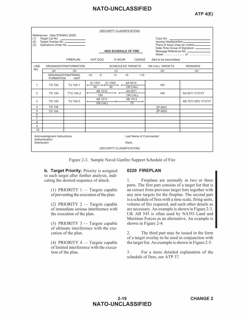
b. Target Priority. Priority is assignedto each target after further analysis, indi-cating the desired sequence of attack.
(1) PRIORITY 1 — Targets capableof preventing the execution of the plan.
(2) PRIORITY 2 — Targets capableof immediate serious interference withthe execution of the plan.
(3) PRIORITY 3 — Targets capableof ultimate interference with the exe-cution of the plan.
(4) PRIORITY 4 — Targets capableof limited interference with the execu-tion of the plan.
0220 FIREPLAN
1. Fireplans are normally in two or threeparts. The first part consists of a target list that isan extract from previous target lists together withany new targets for the fireplan. The second partis a schedule of fires with a time scale, firing units,volume of fire required, and such other details asare necessary. An example is shown in Figure 2-3.UK AB 545 is often used by NATO Land andMaritime Forces as an alternative. An example isshown in Figure 2-4.
2. The third part may be issued in the formof a target overlay to be used in conjunction withthe target list. An example is shown in Figure 2-5.
3. For a more detailed explanation of theschedule of fires, see ATP 37.
2-19 CHANGE 2
NATO-UNCLASSIFIED
NATO-UNCLASSIFIEDATP 4(E)
TG 1045
(SECURITY CLASSIFICATION)
NGS SCHEDULE OF FIRE
References: (See STANAG 2029)(1) Target List No.(2) Target Overlay No.(3) Operations Order No.
Copy No.Issuing HeadquartersPlace of Issue (may be coded)Date-Time Group of SignatureMessage Reference No.Sheet of
FIREPLAN HOT DOG H HOUR 120400Z (Not to be transmitted)
1
LINE ORGANIZATION/FORMATION SCHEDULED TARGETS ON CALL TARGETS REMARKSNO.
(a) (b) (c) (d) (e)
ORGANIZATION/FIRING -10 -5 H +5 +10FORMATION UNIT
Acknowledgment Instructions:Authentication:Distribution:
(SECURITY CLASSIFICATION)
2
3
4
6
7
8
9
10
TG 104
TG 104
TG 104
TU 104.1ZJ 1001 ZJ 1002 AA 0010
50 50 ON CALL
TTU 104.2
TU 104.3
TG 104
Last Name of Commander:
Rank:
+60
+90
ZP 6001
ZP 6002
AA 0011 VT/CVT
AB 1013 50% VT/CVT
AB 1012 AA 0011
100 ON CALL
AB 1013 AB 1013
ON CALL 75
Figure 2-3. Sample Naval Gunfire Support Schedule of Fire

2-20 CHANGE 2
NATO-UNCLASSIFIED
NATO-UNCLASSIFIEDATP 4(E)
Artillery Fire Plan Proforma
Target Information(a) (b) (c) (d) (e)
(f) (g) (h)
Remarks
HMSO Dd 8348590/D2294A, 03/91, GP 5600, CCN 32484
Line Target No. Description Location Alt Remarks
XT 28ØØ
XT 28Ø1
XT 28Ø2
XT 28Ø3
XT 28Ø4
XT 28Ø5
XT 28Ø6
XT 28Ø7
XT 28Ø8
3971
A2Ø Throughout
Line
Regtor
FmnFireUnits
Timings
Fire Plan
1
2
3
4
5
6
7
8
9
10
11
12
Superimposed
AB 545
Revised 8/90
Supporting
H Hour
Originator
Sheet
Modifications by
Date/Time Groupof
Schedule
1
2
3
4
5
6
7
8
(j)
Coy Posn
Coy Posn
SAM SITE
TANKS
SuspectedGunPosn
SuspectedMor Posn
DF 1
DF 2
FPF
814 26Ø
82Ø 265
832 259
828Ø 2715
823Ø 263Ø
831Ø 2645
8195 26Ø6
8215 2685
82Ø9 27Ø5
42Ø
415
42Ø
422
415
418
425
43Ø
416
TO BE ADJUSTED G6X WITHS4H
TO BE ADJUSTED M4N WITHD2S
ALREADY ADJUSTED
PREDICT
PREDICT ON CALL 4 RDS FFE
PREDICT ON CALL 4 RDS FFE
PREDICT ON CALL 3 RDS FFE
PREDICT ON CALL 3 RDS FFE
PREDICT ON CALL 5 RDS FFE
A2Ø
B4Ø
T44
G6X
M4N
SAXON
AXE
T151
ARTY
ARTY
MOR
NGS
NGS
AIR
AIR
AVN
XT 28ØØ
-1Ø -5 HH 5 1Ø 15 2Ø
XT 28Ø1 XT 28Ø8
XT 28ØØ
XT 28Ø2
( a)
XT 28Ø1
XT 28Ø51
( a)
XT 28Ø8
XT 28Ø8
( d)
( a)
( c)
( c)
( f)
R3
( a)
PREDICT ON CALL 4 RDS FFE
( d)
( e)
( e)
( d)
XT 28Ø2
XT 28Ø2
XT 28ØØ
XT 28Ø6
XT 28Ø7
( f)
( g)
( a) 6 Rds Fol by R3
( d) Oncall 5 Rds FFE
XT 28Ø1
XT 28Ø3
( b) Smoke2 Rds Fol by R3
( e) Oncall 3 Rds FFE
( c) 9 Salvos FTE interval 3Ø
( f) 2x Tornados withCBU
( g) 2x TonLYNX - opportunity targets
GSMP
Ø53ØZ
M22
1 1
M22
Ø2Ø1ØØ Z
Figure 2-4. Sample United Kingdom Fire Plan Format (AB 545)

2-21 CHANGE 2
NATO-UNCLASSIFIED
NATO-UNCLASSIFIEDATP 4(E)
(SECURITY CLASSIFICATION)
References:(1) Maps, charts and relevant documents(2) Co-ordinate location system used (specify type
of reference system used, e.g. UTM Grid,Military Grid, etc.)
(SECURITY CLASSIFICATION)
Copy No.Issuing HeadquartersModifications ByPlace of Issue (may be coded)Date-Time Group of SignatureMessage Reference No.
TARGET OVERLAY NO.ISSUED WITH TARGET LIST NO.
(NOT FOR PREDICTED FIRE)
AZ1002
09
49
X
X2 1
AA0010
+AA0120
+AY1007
AA2002
A1H
40
Acknowledgement Instructions:Authentication:
Distribution:
Last name of commander:
Rank:
NOTE: For brevity, some targets are omitted.
09
AA1006
17
50
AA0125
AA1001
AA1005
1 = 2
1 X 2
A2G
Figure 2-5. Sample Target Overlay

SECTION V — REPORTS AND RETURNS
0221 CODE WORDS
1. NGS reports are designed to keep inter-ested agencies informed of NGS status with theminimum of radio traffic. They are made by shipsto the SACC, FSCC, or spotters using the follow-ing standard formats. NGS report forms are pro-vided in Figure 2-6.
a. PEPPER. Nonscheduled Fire Mis-sion Report. Made by ship to SACC assoon as possible after firing.
b. HONEY. New Target Report. Madeby spotters to SACC as soon as possible as
new targets are discovered or when knowntargets are given a corrected location.
c. PICKLE. Unfired Target Report. Madeby ship or spotter to SACC when sched-uled targets cannot be fired or when effec-tiveness is assessed as under 50 percent.
d. CANDY. Ammunition RemainingReport. Sent — coded — in accordancewith the operation order.
e. GURF. Guns Up Ready to Fire Report.Made by ship when coming onto NGS sta-tion. Summarizes NGS capability when itmay be unknown to NGS agencies.
2-22 CHANGE 2
NATO-UNCLASSIFIED
NATO-UNCLASSIFIEDATP 4(E)
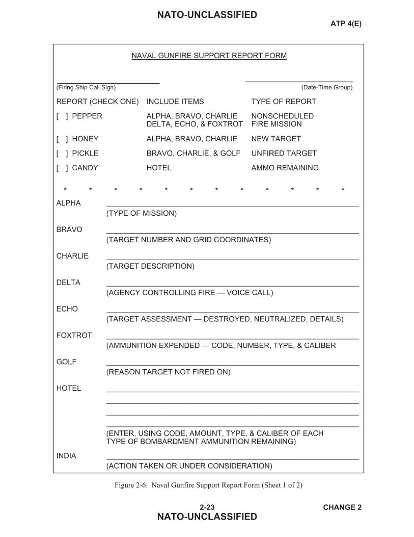
2-23 CHANGE 2
NATO-UNCLASSIFIED
NATO-UNCLASSIFIEDATP 4(E)
NAVAL GUNFIRE SUPPORT REPORT FORM
(Firing Ship Call Sign) (Date-Time Group)
REPORT (CHECK ONE) INCLUDE ITEMS TYPE OF REPORT
[ ] PEPPER ALPHA, BRAVO, CHARLIE NONSCHEDULEDDELTA, ECHO, & FOXTROT FIRE MISSION
[ ] HONEY ALPHA, BRAVO, CHARLIE NEW TARGET
[ ] PICKLE BRAVO, CHARLIE, & GOLF UNFIRED TARGET
[ ] CANDY HOTEL AMMO REMAINING
* * * * * * * * * * * *
ALPHA _____________________________________________________________
(TYPE OF MISSION)
BRAVO _____________________________________________________________
(TARGET NUMBER AND GRID COORDINATES)
CHARLIE _____________________________________________________________
(TARGET DESCRIPTION)
DELTA _____________________________________________________________
(AGENCY CONTROLLING FIRE — VOICE CALL)
ECHO _____________________________________________________________
(TARGET ASSESSMENT — DESTROYED, NEUTRALIZED, DETAILS)
FOXTROT _____________________________________________________________
(AMMUNITION EXPENDED — CODE, NUMBER, TYPE, & CALIBER
GOLF _____________________________________________________________
(REASON TARGET NOT FIRED ON)
HOTEL _____________________________________________________________
___________________________________________________________________
___________________________________________________________________
___________________________________________________________________
(ENTER, USING CODE, AMOUNT, TYPE, & CALIBER OF EACHTYPE OF BOMBARDMENT AMMUNITION REMAINING)
INDIA _____________________________________________________________
(ACTION TAKEN OR UNDER CONSIDERATION)
Figure 2-6. Naval Gunfire Support Report Form (Sheet 1 of 2)

2-24 CHANGE 2
NATO-UNCLASSIFIED
NATO-UNCLASSIFIEDATP 4(E)
GUNS UP AND READY TO FIRE (GURF) REPORT
FROM: SHIP
TO: SFCP/FO PARTY
ALPHA __________________________________________________________________
(CALL SIGN OF SHIP)
BRAVO __________________________________________________________________
(“ON STATION AND READY” AND DTG (LOCAL) END OF NGSASSIGNMENT)
CHARLIE __________________________________________________________________
(PLANNED FIRING LOCATION (GRID COORDINATES). IF THESHIP WILL BE FIRING FROM A TRACK, THE APPROXIMATECENTER OF THE TRACK)
DELTA __________________________________________________________________
__________________________________________________________________
__________________________________________________________________
__________________________________________________________________
(SIGNIFICANT REDUCTION IN CAPABILITY, TO INCLUDE MOUNTCASUALTIES, AMMUNITION SHORTAGES)
ECHO __________________________________________________________________
__________________________________________________________________
__________________________________________________________________
__________________________________________________________________
(ANY OTHER INFORMATION THAT WILL HAVE SIGNIFICANTEFFECT UPON SHIP CAPABILITY TO PROVIDE NGS)
NOTE: DELTA AND ECHO WIL BE DELETED FROM TRANSMISSIONIF NOT APPLICABLE
Figure 2-6. Naval Gunfire Support Report Form (Sheet 2 of 2)

CHAPTER 3
Communications
0301 NAVAL GUNFIRE SUPPORT NETS
1. Minimum Requirement. The minimumnumber of NGS nets required will depend on thesize of the force and the number of NGS assets de-ployed. ATP 37 gives further details on NGScommunications, but for a landing force of regi-mental landing team/brigade size, the minimumnets required are as follows:
a. Naval Gunfire Control Net.
b. Naval Gunfire Ground Spot Net.
c. Naval Gunfire Airspot Net.
d. Landing Force Naval Gunfire SupportNet (HF).
e. Landing Force Naval Gunfire SupportNet (see paragraph 0301.6).
f. Forward Observer Party Net (see para-graph 0301.6).
g. Shore Fire Control Party Local Net(see paragraph 0301.6).
2. Naval Gunfire Control Net. This net isnormally established by the operations order priorto NGS activities. It provides the OTC, who is netcontrol, with the means to control and coordinatethe activities of all naval gunfire support agen-cies. It is guarded by all fire support ships andby designated headquarters ashore. Also, groundspotters may pass a request for support on this netand shall keep watch on this net when they are notassigned to support ships. This net, which is in-tended primarily for operational traffic, may be-come overloaded if there are many support ships.Consequently, overload nets may be required tohandle separately the administrative traffic. Thenaval gunfire representative of the OTC may usethe naval gunfire control net to:
a. Assign fire support ships to spotters.
b. Relieve and reassign fire support ships.
c. Pass information regarding ammuni-tion levels, when tactical circumstances sorequire.
d. Pass intelligence affecting NGS.
e. Pass information regarding prear-ranged fires.
f. Receive shore requests regarding sup-port requirements.
g. Pass information regarding trajectory.
h. Pass orders and instructions relative tomassing of fires, time on target, and liftingof fires.
i. Request services of an airborne spotter.
3. Naval Gunfire Ground Spot Net. Thisnet enables a ground spotter, who is assigned asupport ship, to call for and adjust naval gunfire.If the spotter does not establish communicationswithin 10 minutes of allocation, he is to return tothe control net and report. When a sufficient num-ber of frequencies is available, each net should beassigned a separate clear frequency. Dependingon standing operating procedures, net control iseither the NGLO (or his equivalent) or the groundspotter. He normally employs low-powered,high-frequency radio equipment to call the as-signed ship to establish the net. The ship setswatch either 30 minutes before firing is scheduledto commence, or from whenever the ship is allo-cated to the spotter, if less than 30 minutes remainbefore firing is scheduled to commence. The spot-ter makes repeated calls to the ship until commu-nications are established. The ship normallyshould not transmit until called.
4. Naval Gunfire Airspot Net. This netprovides communication between an airborne spot-ter and a support ship. Depending on standingoperating procedures, net control is either the NGLOor the airborne spotter. The net normally is em-ployed to call for and adjust fire. When equipmentand available frequencies permit, each net should
3-1 CHANGE 2
NATO-UNCLASSIFIED
NATO-UNCLASSIFIEDATP 4(E)

be assigned a frequency in the VHF/UHF band.Ships carrying their own spotting aircraft employairborne spotters, as required, using call signs andfrequencies assigned in the operation plan or or-der. Ships not carrying their own spotting aircraftordinarily do not initiate requests for airbornespotters. Rather, a force ashore or the headquar-ters ship normally originates a request for an air-borne spotter. The airborne spotter is briefedseparately and reports to air control for last min-ute instructions before calling the support ship.(He reports to air control again when released bythe support ship.) Establishment of the net is initi-ated by the airborne spotter calling his assignedsupport ship. Obviously, aircraft radio tuning priorto takeoff must be accurate to avoid loss of effi-ciency and mutual interference with other circuits.Employment of preset crystal-controlled channelswill improve flexibility and speed in use of air-borne spotters.
5. Landing Force Naval Gunfire Sup-port Net (HF). This net provides a means forrequesting NGS and coordinating the employ-ment of gunfire support ships in general supportof the landing force. The net is guarded by, andprovides radio communications for, the landingforce NGFO (net control), NGFOs with subordi-nate units, and ships in general support of thelanding force.
6. Landing Force Naval Gunfire Sup-port Net, Forward Observer Party Net, andShore Fire Control Party Local Net.Thesenets are for the same purpose using different ter-minology. They provide communications betweenspotters, FSCCs, and the NGLOs and are used forthe passage of information, routine reports, orders,and general information.
0302 PROCEDURES
1. General. The communication proce-dures in ACP 124 and 125 are used in NGS. How-ever, these procedures may be abbreviated whenthere is no danger of confusion, for example:
a. After the warning order in the call forfire, call signs may be omitted.
b. Use of procedural words and phrasesmay be limited.
c. A short-phrase, report-back method oftransmission may be automatically ac-complished without special operatinginstructions.
d. Departure may be made from normalor abbreviated message format.
2. Precedence. A request for support, anallotment, or a call for fire will be consideredequivalent to an IMMEDIATE message and willbe accorded the considerations of that prece-dence, although the word “IMMEDIATE” is notincluded in the message heading.
3. Call Signs and Frequencies. To per-mit flexibility in the employment and assignmentof firing ships, each ship, spotter, and NGLO shallbe furnished with a list of call signs and frequen-cies assigned to all NGS forces. Call signs andfrequencies will be allocated in the communica-tions plan by the appropriate authority.
4. Codes and Ciphers. In selecting anddesignating codes and ciphers to be employed byspotters and NGLOs, due consideration must begiven to the possibility of capture or compromise.
5. Authentication. The possibility that en-emy radio stations might employ deception in or-der to gain information or cause own fire onfriendly forces demands that detailed proceduresbe employed for the use of authentication. Toavoid deception, the ship should initiate authenti-cation procedures upon establishing initial com-munications with the spotter on an uncovered net.Authentication procedures will be found in theapplicable operation order.
3-2 CHANGE 2
NATO-UNCLASSIFIED
NATO-UNCLASSIFIEDATP 4(E)

ANNEX A
Examples
A101 LIST OF EXAMPLES
1. Request for support and allotment signal,Figure A-1.
2. Engagement of an area target, Figure A-2.
3. Engagement of a point target, Figure A-3.
4. Engagement with an airborne observer,Figure A-4.
5. Engagement with fuze time, Figure A-5.
6. Engagement with fuze VT/CVT, FigureA-6.
7. Engagement with danger close, FigureA-7.
8. Engagement with ship adjust, Figure A-8.
9. Engagement of a recorded target, FigureA-9.
10. Fresh target shift, Figure A-10.
11. Engagement of new target, Figure A-11.
12. Continuous illumination, Figure A-12.
13. Simultaneous illumination of two targets,Figure A-13.
14. Coordinated illumination, Figure A-14.
15. Coordinated illumination — Standardinterval, Figure A-15.
16. SEAD engagement with suppressionrounds, Figure A-16.
17. SEAD engagement with suppression andmarking rounds, Figure A-17.
A102 NOTES ON EXAMPLES
1. Call signs used:
Y2P Ship
C5E Ground Spotter
A3Z Air Spotter
2. Communications are assumed to havebeen established.
3. Authentication has not been shown.
4. The examples given are written with theobject of bringing out as many procedural pointsas possible.
A-1 CHANGE 2
NATO-UNCLASSIFIED
NATO-UNCLASSIFIEDATP 4(E)
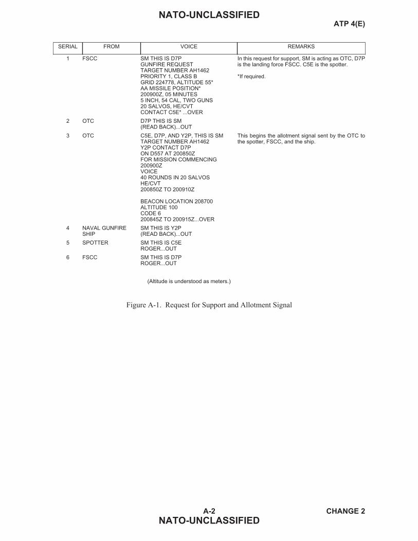
A-2 CHANGE 2
NATO-UNCLASSIFIED
NATO-UNCLASSIFIEDATP 4(E)
SERIAL FROM VOICE REMARKS
1 FSCC SM THIS IS D7PGUNFIRE REQUESTTARGET NUMBER AH1462PRIORITY 1, CLASS BGRID 224778, ALTITUDE 55*AA MISSILE POSITION*200900Z, 05 MINUTES5 INCH, 54 CAL, TWO GUNS20 SALVOS, HE/CVTCONTACT C5E* ...OVER
In this request for support, SM is acting as OTC, D7Pis the landing force FSCC. C5E is the spotter.
*If required.
2 OTC D7P THIS IS SM(READ BACK)...OUT
3 OTC C5E, D7P, AND Y2P, THIS IS SMTARGET NUMBER AH1462Y2P CONTACT D7PON D557 AT 200850ZFOR MISSION COMMENCING200900ZVOICE40 ROUNDS IN 20 SALVOSHE/CVT200850Z TO 200910Z
BEACON LOCATION 208700ALTITUDE 100CODE 6200845Z TO 200915Z...OVER
This begins the allotment signal sent by the OTC tothe spotter, FSCC, and the ship.
4 NAVAL GUNFIRESHIP
SM THIS IS Y2P(READ BACK)...OUT
5 SPOTTER SM THIS IS C5EROGER...OUT
6 FSCC SM THIS IS D7PROGER...OUT
(Altitude is understood as meters.)
Figure A-1. Request for Support and Allotment Signal
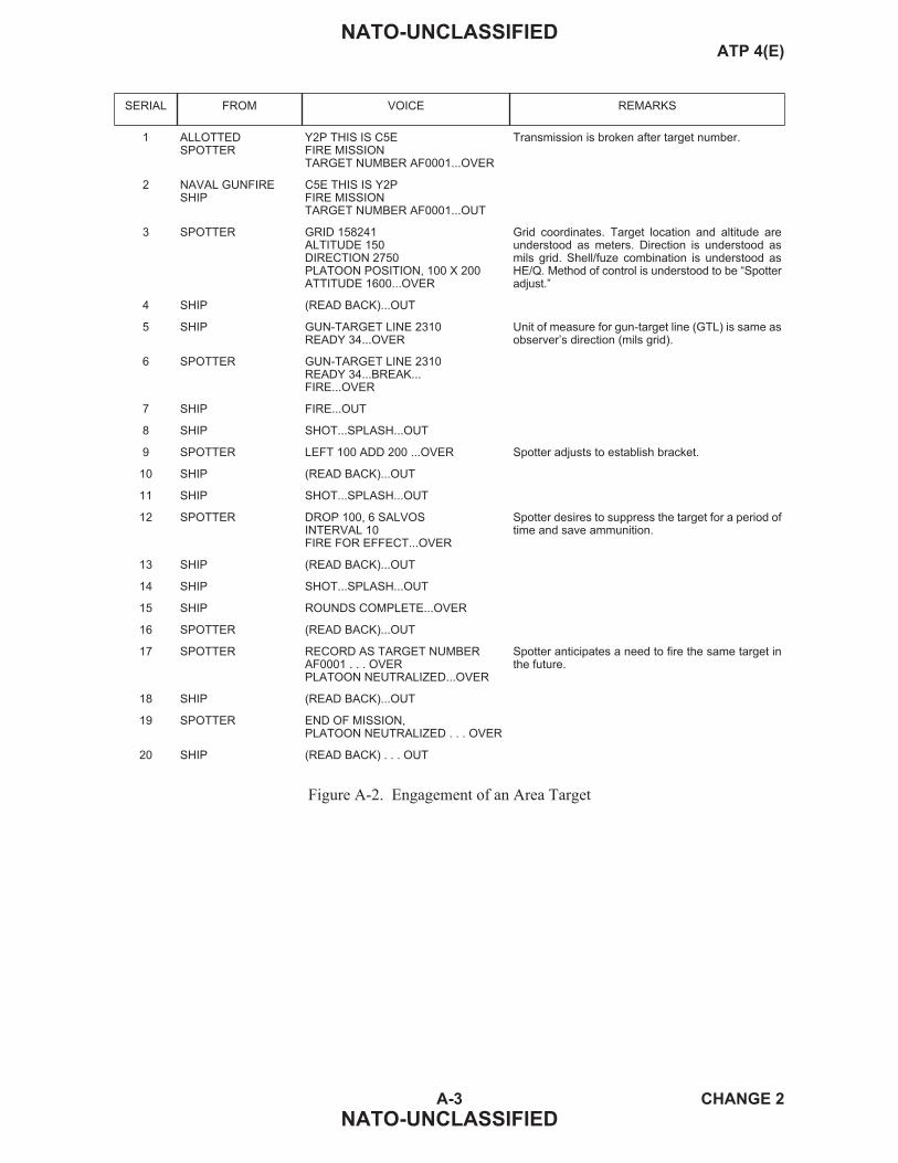
A-3 CHANGE 2
NATO-UNCLASSIFIED
NATO-UNCLASSIFIEDATP 4(E)
SERIAL FROM VOICE REMARKS
1 ALLOTTEDSPOTTER
Y2P THIS IS C5EFIRE MISSIONTARGET NUMBER AF0001...OVER
Transmission is broken after target number.
2 NAVAL GUNFIRESHIP
C5E THIS IS Y2PFIRE MISSIONTARGET NUMBER AF0001...OUT
3 SPOTTER GRID 158241ALTITUDE 150DIRECTION 2750PLATOON POSITION, 100 X 200ATTITUDE 1600...OVER
Grid coordinates. Target location and altitude areunderstood as meters. Direction is understood asmils grid. Shell/fuze combination is understood asHE/Q. Method of control is understood to be “Spotteradjust.”
4 SHIP (READ BACK)...OUT
5 SHIP GUN-TARGET LINE 2310READY 34...OVER
Unit of measure for gun-target line (GTL) is same asobserver’s direction (mils grid).
6 SPOTTER GUN-TARGET LINE 2310READY 34...BREAK...FIRE...OVER
7 SHIP FIRE...OUT
8 SHIP SHOT...SPLASH...OUT
9 SPOTTER LEFT 100 ADD 200 ...OVER Spotter adjusts to establish bracket.
10 SHIP (READ BACK)...OUT
11 SHIP SHOT...SPLASH...OUT
12 SPOTTER DROP 100, 6 SALVOSINTERVAL 10FIRE FOR EFFECT...OVER
Spotter desires to suppress the target for a period oftime and save ammunition.
13 SHIP (READ BACK)...OUT
14 SHIP SHOT...SPLASH...OUT
15 SHIP ROUNDS COMPLETE...OVER
16 SPOTTER (READ BACK)...OUT
17 SPOTTER RECORD AS TARGET NUMBERAF0001 . . . OVERPLATOON NEUTRALIZED...OVER
Spotter anticipates a need to fire the same target inthe future.
18 SHIP (READ BACK)...OUT
19 SPOTTER END OF MISSION,PLATOON NEUTRALIZED . . . OVER
20 SHIP (READ BACK) . . . OUT
Figure A-2. Engagement of an Area Target

A-4 CHANGE 2
NATO-UNCLASSIFIED
NATO-UNCLASSIFIEDATP 4(E)
SERIAL FROM VOICE REMARKS
1 ALLOTTEDSPOTTER
Y2P THIS IS C5EFIRE MISSIONTARGET NUMBER AF0002...OVER
Transmission is broken after target number.
2 NAVAL GUNFIRESHIP
C5E THIS IS Y2PFIRE MISSIONTARGET NUMBER AF0002...OUT
3 SPOTTER DIRECTION 1670DISTANCE 2400DOWN 40MACHINE GUN...OVER
Polar plot. Direction is understood as mils grid,altitude as meters, shell/fuze combination to beHE/Q, and method of control to be “Spotter adjust.”
4 SHIP (READ BACK)...OUT
5 SHIP GUN-TARGET LINE 3200READY 34...OVER
6 SPOTTER GUN-TARGET LINE 3200READY 34... BREAK...FIRE...OVER
7 SHIP FIRE...OUT
8 SHIP SHOT...SPLASH...OUT
9 SPOTTER LEFT 100 ADD 200 ...OVER Spotter adjusts to establish bracket.
10 SHIP (READ BACK)...OUT
11 SHIP SHOT...SPLASH...OUT
12 SPOTTER RIGHT 30 DROP 100 ...OVER
13 SHIP (READ BACK)...OUT
14 SHIP SHOT...SPLASH...OUT
15 SPOTTER DROP 50 15 SALVOSFIRE FOR EFFECT...OVER
Spotter splits 100-meter bracket.
16 SHIP (READ BACK)...OUT
17 SHIP SHOT...SPLASH...OUT
18 SHIP ROUNDS COMPLETE...OVER
19 SPOTTER (READ BACK)...OUT
20 SPOTTER TREND SOUTHWEST 20 PERSALVOLEFT 200 ADD 200REPEAT...OVER
Spotter has observed a trend of fire-for-effect salvosto the southwest.
21 SHIP (READ BACK)...OUT
22 SHIP SHOT...SPLASH...OUT
23 SHIP ROUNDS COMPLETE...OVER
24 SPOTTER (READ BACK)...OUT
25 SPOTTER END OF MISSIONMACHINE GUN SILENCED...OVER
26 SHIP (READ BACK)...OUT
Figure A-3. Engagement of a Point Target

A-5 CHANGE 2
NATO-UNCLASSIFIED
NATO-UNCLASSIFIEDATP 4(E)
SERIAL FROM VOICE REMARKS
1 ALLOTTEDSPOTTER
Y2P THIS IS A3ZFIRE MISSIONTARGET NUMBER AF0003...OVER
Transmission is broken after target number.
2 NAVAL GUNFIRESHIP
A3Z THIS IS Y2PFIRE MISSIONTARGET NUMBER AF0003...OUT
3 SPOTTER GRID 285175ALTITUDE 480 FEETDIRECTION GUN-TARGET LINEASSEMBLY AREAAT MY COMMAND...OVER
Grid coordinates. Unit of measure is transmitted, asit differs from standard. Shell/fuze combination isunderstood as HE/Q. Spotter desires to control thefiring of each adjustment.
4 SHIP (READ BACK)...OUT
5 SHIP GUN-TARGET LINE 1130SUMMIT 6,000 FEETREADY 24...OVER
Ship must transmit summit in feet to an airbornespotter.
6 SPOTTER (READ BACK)...OUT
7 SHIP READY 24...OVER
8 SPOTTER READY 24...BREAK...FIRE...OVER
9 SHIP SHOT...SPLASH...OUT
10 SPOTTER RIGHT 40 ADD 200 ...OVER Spotter adjusts to establish bracket.
11 SHIP (READ BACK)...OUT
12 SHIP READY...OVER
13 SPOTTER CHECK FIRING...OVER Used by spotter to interrupt firing temporarily, usuallyfor safety reasons.
14 SHIP (READ BACK)...OUT
15 SPOTTER CANCEL CHECK FIRING...FIRE...OVER
Must be canceled by the same station that initiates it.
16 SHIP (READ BACK)...OUT
17 SHIP SHOT...SPLASH...OUT
18 SPOTTER DROP 100 15 SALVOSFIRE FOR EFFECT...OVER
Spotter has split 200-meter bracket.
19 SHIP (READ BACK)...OUT
20 SHIP READY...OVER
21 SPOTTER READY...FIRE...OVER
22 SHIP FIRE...OUT
23 SHIP SHOT...SPLASH...OUT
24 SHIP ROUNDS COMPLETE...OVER
25 SPOTTER ROUNDS COMPLETE...OUT
26 SPOTTER END OF MISSION20 CASUALTIES...OVER
27 SHIP (READ BACK)...OUT
Figure A-4. Engagement With an Airborne Observer
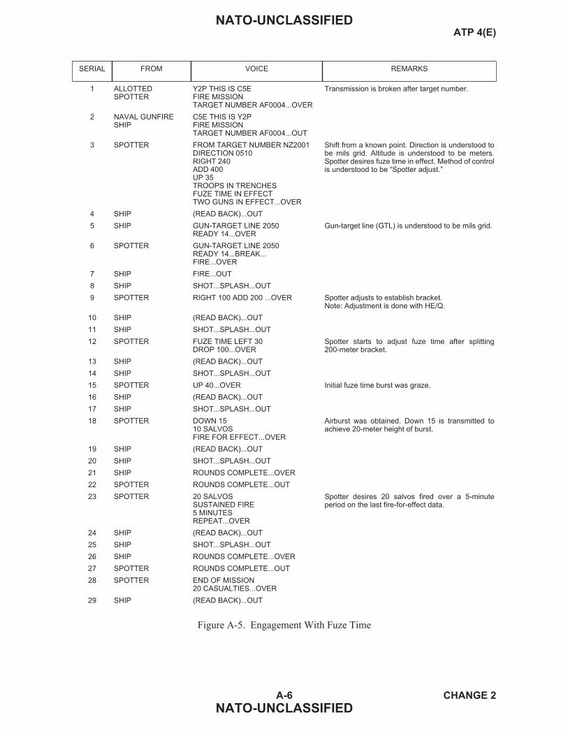
A-6 CHANGE 2
NATO-UNCLASSIFIED
NATO-UNCLASSIFIEDATP 4(E)
SERIAL FROM VOICE REMARKS
1 ALLOTTEDSPOTTER
Y2P THIS IS C5EFIRE MISSIONTARGET NUMBER AF0004...OVER
Transmission is broken after target number.
2 NAVAL GUNFIRESHIP
C5E THIS IS Y2PFIRE MISSIONTARGET NUMBER AF0004...OUT
3 SPOTTER FROM TARGET NUMBER NZ2001DIRECTION 0510RIGHT 240ADD 400UP 35TROOPS IN TRENCHESFUZE TIME IN EFFECTTWO GUNS IN EFFECT...OVER
Shift from a known point. Direction is understood tobe mils grid. Altitude is understood to be meters.Spotter desires fuze time in effect. Method of controlis understood to be “Spotter adjust.”
4 SHIP (READ BACK)...OUT
5 SHIP GUN-TARGET LINE 2050READY 14...OVER
Gun-target line (GTL) is understood to be mils grid.
6 SPOTTER GUN-TARGET LINE 2050READY 14...BREAK...FIRE...OVER
7 SHIP FIRE...OUT
8 SHIP SHOT...SPLASH...OUT
9 SPOTTER RIGHT 100 ADD 200 ...OVER Spotter adjusts to establish bracket.Note: Adjustment is done with HE/Q.
10 SHIP (READ BACK)...OUT
11 SHIP SHOT...SPLASH...OUT
12 SPOTTER FUZE TIME LEFT 30DROP 100...OVER
Spotter starts to adjust fuze time after splitting200-meter bracket.
13 SHIP (READ BACK)...OUT
14 SHIP SHOT...SPLASH...OUT
15 SPOTTER UP 40...OVER Initial fuze time burst was graze.
16 SHIP (READ BACK)...OUT
17 SHIP SHOT...SPLASH...OUT
18 SPOTTER DOWN 1510 SALVOSFIRE FOR EFFECT...OVER
Airburst was obtained. Down 15 is transmitted toachieve 20-meter height of burst.
19 SHIP (READ BACK)...OUT
20 SHIP SHOT...SPLASH...OUT
21 SHIP ROUNDS COMPLETE...OVER
22 SPOTTER ROUNDS COMPLETE...OUT
23 SPOTTER 20 SALVOSSUSTAINED FIRE5 MINUTESREPEAT...OVER
Spotter desires 20 salvos fired over a 5-minuteperiod on the last fire-for-effect data.
24 SHIP (READ BACK)...OUT
25 SHIP SHOT...SPLASH...OUT
26 SHIP ROUNDS COMPLETE...OVER
27 SPOTTER ROUNDS COMPLETE...OUT
28 SPOTTER END OF MISSION20 CASUALTIES...OVER
29 SHIP (READ BACK)...OUT
Figure A-5. Engagement With Fuze Time

A-7 CHANGE 2
NATO-UNCLASSIFIED
NATO-UNCLASSIFIEDATP 4(E)
SERIAL FROM VOICE REMARKS
1 ALLOTTEDSPOTTER
Y2P THIS IS C5EFIRE MISSIONTARGET NUMBER AF0005...OVER
Transmission is broken after target number.
2 NAVAL GUNFIRESHIP
C5E THIS IS Y2PFIRE MISSIONTARGET NUMBER AF0005...OUT
3 SPOTTER DIRECTION 2160DISTANCE 2400DOWN 30TRUCK PARKREDUCED CHARGEFUZE CVT10 SALVOSFIRE FOR EFFECT...OVER
Polar plot. Direction is understood to be mils grid.Distance and altitude are understood to be meters.Spotter desires fuze CVT, reduced charge, andimmediate fire for effect. Fuze VT may be used whenno CVT fuzes are available.
4 SHIP (READ BACK)...OUT
5 SHIP GUN-TARGET LINE 6350READY 38...OVER
Gun-target line (GTL) is understood to be mils grid.
6 SPOTTER GUN-TARGET LINE 6350READY 38... BREAK...FIRE...OVER
7 SHIP FIRE...OUT
8 SHIP SHOT...SPLASH...OUT
9 SHIP ROUNDS COMPLETE...OVER
10 SPOTTER ROUNDS COMPLETE...OUT
11 SPOTTER END OF MISSION8 TRUCKS DESTROYED...OVER
12 SHIP (READ BACK)...OUT
Figure A-6. Engagement With Fuze VT/CVT

A-8 CHANGE 2
NATO-UNCLASSIFIED
NATO-UNCLASSIFIEDATP 4(E)
SERIAL FROM VOICE REMARKS
1 ALLOTTEDSPOTTER
Y2P THIS IS C5EFIRE MISSIONTARGET NUMBER AF0006...OVER
Transmission is broken after target number.
2 NAVAL GUNFIRESHIP
C5E THIS IS Y2PFIRE MISSIONTARGET NUMBER AF0006...OUT
3 SPOTTER FROM TARGET NUMBER AB4000DIRECTION 3210RIGHT 120 ADD 400 UP 30AUTOMATIC WEAPONDANGER CLOSE NORTHEAST 300FIRST SALVO AT ADD 450...OVER
Shift from a known point. Direction is understood asmils grid. Friendly troops are located 300 metersnortheast of target. For safety, the spotter desiresthe first salvo to be fired 450 meters beyond thetarget along the observer-target line (OTL).
4 SHIP (READ BACK)...OUT
5 SHIP GUN-TARGET LINE 6400FIRST SALVO AT ADD 450READY 26...OVER
Gun-target line (GTL) is understood to be mils grid.
6 SPOTTER GUN-TARGET LINE 6400FIRST SALVO AT ADD 450READY 26...BREAK...FIRE...OVER
7 SHIP FIRE...OUT
8 SHIP SHOT...SPLASH...OUT
9 SPOTTER LEFT 50 DROP 100 ...OVER
10 SHIP (READ BACK)...OUT
11 SHIP SHOT...SPLASH...OUT
12 SPOTTER DROP 100...OVER Spotter is creeping due to danger close situation.
13 SHIP (READ BACK)...OUT
14 SHIP SHOT...SPLASH...OUT
15 SPOTTER DROP 5010 SALVOSFIRE FOR EFFECT...OVER
16 SHIP (READ BACK)...OUT
17 SHIP SHOT...SPLASH...OUT
18 SHIP ROUNDS COMPLETE...OVER
19 SPOTTER ROUNDS COMPLETE...OUT
20 SPOTTER END OF MISSIONAUTOMATIC WEAPONDESTROYED...OVER
21 SHIP (READ BACK)...OUT
Figure A-7. Engagement With Danger Close

A-9 CHANGE 2
NATO-UNCLASSIFIED
NATO-UNCLASSIFIEDATP 4(E)
SERIAL FROM VOICE REMARKS
1 ALLOTTEDSPOTTER
Y2P THIS IS C5EFIRE MISSIONTARGET NUMBER AF0007...OVER
Transmission is broken after target number.
2 NAVAL GUNFIRESHIP
C5E THIS IS Y2PFIRE MISSIONTARGET NUMBER AF0007...OUT
3 SPOTTER DIRECTION 078 DEGREESMAGNETICDISTANCE 3000DOWN 40TANK COLUMNSHIP ADJUST...OVER
Polar plot. Spotter determines that the ship is bestable to engage the target with direct fire.
4 SHIP (READ BACK)...OUT Ship will engage the target. Spotter will providerange-error spottings if required. Spotter will alsoprovide surveillance.
Figure A-8. Engagement With Ship Adjust
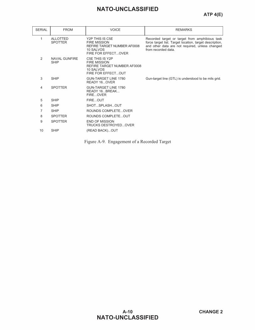
A-10 CHANGE 2
NATO-UNCLASSIFIED
NATO-UNCLASSIFIEDATP 4(E)
SERIAL FROM VOICE REMARKS
1 ALLOTTEDSPOTTER
Y2P THIS IS C5EFIRE MISSIONREFIRE TARGET NUMBER AF000810 SALVOSFIRE FOR EFFECT...OVER
Recorded target or target from amphibious taskforce target list. Target location, target description,and other data are not required, unless changedfrom recorded data.
2 NAVAL GUNFIRESHIP
C5E THIS IS Y2PFIRE MISSIONREFIRE TARGET NUMBER AF000810 SALVOSFIRE FOR EFFECT...OUT
3 SHIP GUN-TARGET LINE 1780READY 16...OVER
Gun-target line (GTL) is understood to be mils grid.
4 SPOTTER GUN-TARGET LINE 1780READY 16...BREAK...FIRE...OVER
5 SHIP FIRE...OUT
6 SHIP SHOT...SPLASH...OUT
7 SHIP ROUNDS COMPLETE...OVER
8 SPOTTER ROUNDS COMPLETE...OUT
9 SPOTTER END OF MISSIONTRUCKS DESTROYED...OVER
10 SHIP (READ BACK)...OUT
Figure A-9. Engagement of a Recorded Target

A-11 CHANGE 2
NATO-UNCLASSIFIED
NATO-UNCLASSIFIEDATP 4(E)
SERIAL FROM VOICE REMARKS
1 ALLOTTEDSPOTTER
Y2P THIS IS C5EFIRE MISSIONTARGET NUMBER AF0011...OVER
Transmission is broken after target number.
2 NAVAL GUNFIRESHIP
C5E THIS IS Y2PFIRE MISSIONTARGET NUMBER AF0011...OUT
3 SPOTTER GRID 132546ALTITUDE 70DIRECTION 2480TROOPS DUG INFUZE CVT IN EFFECT...OVER
Grid coordinates. Altitude is understood to bemeters. Direction is understood to be mils grid.Method of control is understood to be “Spotteradjust.”
4 SHIP (READ BACK)...OUT
5 SHIP GUN-TARGET LINE 2560READY 16...OVER
Gun-target line (GTL) is understood to be mils grid.
6 SPOTTER GUN-TARGET LINE 2560READY 16...BREAK...FIRE...OVER
7 SHIP FIRE...OUT
8 SHIP SHOT...SPLASH...OUT
9 SPOTTER RIGHT 180 ADD 400 ...OVER Spotter adjusts to establish bracket.
10 SHIP (READ BACK)...OUT
11 SHIP SHOT...SPLASH...OUT
12 SPOTTER FRESH TARGETTARGET NUMBER AF0012RIGHT 600 ADD 400 UP 40TRUCK CONVOY...OVER
Fresh target location is given from the impact of lastround fired. Only those elements that are differentfrom the original call for fire are transmitted.
13 SHIP (READ BACK)...OUT
14 SHIP SHOT...SPLASH...OUT
15 SPOTTER DIRECTION 2700DROP 2006 SALVOSFIRE FOR EFFECT...OVER
Direction to fresh target is given after first round isfired.
16 SHIP (READ BACK)...OUT
17 SHIP 12 SHOT...SPLASH...OUT
18 SHIP 12 ROUNDS COMPLETE...OVER
19 SPOTTER 12 ROUNDS COMPLETE...OUT
20 SPOTTER FRESH TARGETTARGET NUMBER AF0011LEFT 600 DROP 100 DOWN 40ENEMY TROOPS DUG INSPOTTER ADJUST...OVER
Spotter goes back to adjustment on original target.
21 SHIP (READ BACK)...OUT
22 SHIP 11 SHOT...SPLASH...OUT
23 SPOTTER 11 DIRECTION 2480ADD 1005 SALVOSFIRE FOR EFFECT...OVER
24 SHIP (READ BACK)...OUT
25 SHIP 11 SHOT...SPLASH...OUT
26 SHIP 11 ROUNDS COMPLETE...OVER
27 SPOTTER 11 ROUNDS COMPLETE...OUT
Figure A-10. Fresh Target Shift (Sheet 1 of 2)

A-12 CHANGE 2
NATO-UNCLASSIFIED
NATO-UNCLASSIFIEDATP 4(E)
SERIAL FROM VOICE REMARKS
28 SPOTTER 11 END OF MISSIONTROOPS DISPERSING12 END OF MISSIONTWO TRUCKS DESTROYED...OVER
End-of-mission data is given in target numbersequence.
29 SHIP (READ BACK)...OUT
Figure A-10. Fresh Target Shift (Sheet 2 of 2)

A-13 CHANGE 2
NATO-UNCLASSIFIED
NATO-UNCLASSIFIEDATP 4(E)
SERIAL FROM VOICE REMARKS
1 ALLOTTEDSPOTTER
Y2P THIS IS C5EFIRE MISSIONTARGET NUMBER AF0011...OVER
Transmission is broken after target number.
2 SHIP (READ BACK)...OUT
3 SPOTTER GRID 132546 ALTITUDE 70DIRECTION 2480TROOPS DUG INFUZE CVT IN EFFECT...OVER
Direction is understood to be mils grid, altitude isunderstood to be meters. Spotter desires fuze CVTin effect.
4 SHIP (READ BACK)...OUT
5 SHIP GUN-TARGET LINE 4800READY 16...OVER
6 SPOTTER GUN-TARGET LINE 4800READY 16...BREAK...FIRE...OVER
7 SHIP FIRE...OUT
8 SHIP SHOT...SPLASH...OUT
9 SPOTTER RIGHT 50 ADD 400 ...OVER
10 SHIP (READ BACK)...OUT
11 SHIP SHOT...SPLASH...OUT
12 SPOTTER NEW TARGETTARGET NUMBER AF0012FROM LAST SALVODIRECTION 2600LEFT 400 DROP 600TRUCK CONVOYAT MY COMMAND...OVER
Spotter sees another target (AF0012) that he wishesto engage while simultaneously engaging theoriginal target (AF0011). To indicate that he wishesto engage both targets simultaneously, he uses thewords “New target.” The location of the new target isindicated using any of the three standard methods oftarget location.
13 SHIP (READ BACK)...OUT
14 SHIP 12 GUN-TARGET LINE 5000READY 16...OVER
Since the ship is now firing at two different targets, itmust preface all transmissions with the targetnumber. (To reduce the length of the transmission,only the last two digits of the target number may beused.)
15 SPOTTER (READ BACK) 12...FIRE...OVER
16 SHIP 12 FIRE...OUT
17 SHIP 12 SHOT...SPLASH...OUT
18 SPOTTER 11 DROP 200...BREAK12 LEFT 50 DROP 400...OVER
Since the spotter is correcting the fall of shot ontotwo different targets, he must preface all transmis-sions with the target number. (To reduce the lengthof the transmission, only the last two digits of the tar-get number may be used.)
19 SHIP (READ BACK)...OUT
20 SHIP 11 SHOT...SPLASH...OUT
21 SPOTTER 11 ADD 50 5 SALVOSFIRE FOR EFFECT...OVER
22 SHIP (READ BACK)...OUT
23 SHIP 12 READY...OVER
24 SPOTTER 12 READY...BREAK...FIRE...OVER
25 SHIP 12...FIRE...OUT
Figure A-11. Engagement of New Targets (Sheet 1 of 2)

A-14 CHANGE 2
NATO-UNCLASSIFIED
NATO-UNCLASSIFIEDATP 4(E)
SERIAL FROM VOICE REMARKS
26 SHIP 12 SHOT...SPLASH ...OUT
27 SHIP 11 SHOT...SPLASH...BREAK11 ROUNDS COMPLETE...OVER
28 SPOTTER 11 ROUNDS COMPLETE11 END OF MISSION...OVER
At this point the spotter may end the mission fortarget number AF0011 in order to free the ship foranother target.
29 SHIP 11 END OF MISSION...OUT Target AF0012 is now the only target being engagedso it is no longer necessary to preface orders withtarget numbers. Spotter may also give TargetAF0011 damage assessment now.
30 SPOTTER ADD 100, 6 SALVOSFIRE FOR EFFECT...OVER
31 SHIP (READ BACK)...OUT
32 SHIP READY...OVER
33 SPOTTER READY...BREAK...FIRE...OVER
34 SHIP FIRE...OUT
35 SHIP SHOT...SPLASH...BREAKROUNDS COMPLETE...OVER
36 SPOTTER ROUNDS COMPLETE...OUT
37 SPOTTER 12 END OF MISSIONTRUCK CONVOY DISPERSED11 END OF MISSIONTROOPS DISPERSED...OVER
Spotter ends the mission and gives damageassessment for both targets. (Damage assessmentfor one target is omitted if already sent.)
38 SHIP (READ BACK)...OUT
Figure A-11. Engagement of New Targets (Sheet 2 of 2)

A-15 CHANGE 2
NATO-UNCLASSIFIED
NATO-UNCLASSIFIEDATP 4(E)
SERIAL FROM VOICE REMARKS
1 ALLOTTEDSPOTTER
Y2P THIS IS C5EFIRE MISSIONTARGET NUMBER AF0013...OVER
Transmission is broken after target number.
2 NAVAL GUNFIRESHIP
C5E THIS IS Y2PFIRE MISSIONTARGET NUMBER AF0013...OUT
3 SPOTTER GRID 129871ALTITUDE 80DIRECTION 1620RIVER CROSSINGCONTINUOUS ILLUMINATION...OVER
Grid coordinates. Altitude is understood as meters.direction is understood as mils grid, method ofcontrol is understood to be “Spotter adjust.
4 SHIP (READ BACK)...OUT
5 SHIP LINE OF FIRE 1850READY 36....OVER
Line of fire is understood to be mils grid.
6 SPOTTER LINE OF FIRE 1850READY 36...BREAK...FIRE...OVER
7 SHIP FIRE...OUT
8 SHIP SHOT...SPLASH...OUT
9 SPOTTER RIGHT 200, ADD 400UP 100...OVER
10 SHIP (READ BACK)...OUT
11 SHIP SHOT...SPLASH...OUT
12 SPOTTER DROP 200...OVER
13 SHIP (READ BACK)...OUT
14 SHIP SHOT...SPLASH...OUT
15 SPOTTER 10 SALVOSFIRE FOR EFFECT....OVER
By not specifying the interval of sustained fire, thespotter has acknowledged that he would like thestandard interval for the ammunition in use.
16 SHIP (READ BACK)...OUT
17 SHIP SHOT...SPLASH...OUT
18 SHIP ROUNDS COMPLETE...OVER
19 SPOTTER ROUNDS COMPLETE...OUT
20 SPOTTER END OF MISSIONLIGHT ACTIVITYTROOPS IN OPEN ENGAGEDWITH SMALL ARMS FIRE...OVER
21 SHIP (READ BACK)...OUT
Figure A-12. Continuous Illumination

A-16 CHANGE 2
NATO-UNCLASSIFIED
NATO-UNCLASSIFIEDATP 4(E)
SERIAL FROM VOICE REMARKS
1 ALLOTTEDSPOTTER
Y2P THIS IS C5EFIRE MISSIONTARGET NUMBER AF0015...OVER
Transmission is broken after target number.
2 NAVAL GUNFIRESHIP
C5E THIS IS Y2PFIRE MISSIONTARGET NUMBER AF0015...OUT
3 SPOTTER GRID 465718ALTITUDE 150DIRECTION 216 DEGREES GRIDCOMPANY AREACONTINUOUS ILLUMINATION...OVER
Grid coordinates. Altitude is understood as meters.Unit of measure for direction is transmitted, as itdiffers from standard. Method of control isunderstood to be “Spotter adjust.”
4 SHIP (READ BACK)...OUT
5 SHIP LINE OF FIRE 160 DEGREES GRIDREADY 42...OVER
Ship provides gun-target line (GTL) in same units ofmeasure as spotter’s direction (degrees grid).
6 SPOTTER LINE OF FIRE 160 DEGREES GRIDREADY 42...BREAK...FIRE...OVER
7 SHIP FIRE...OUT
8 SHIP SHOT...SPLASH...OUT
9 SPOTTER Y2P THIS IS C5EFIRE MISSIONTARGET NUMBER AF0016GRID 480720ALTITUDE 200DIRECTION 219 DEGREES GRIDSUSPECTED TROOP MOVEMENTCONTINUOUS ILLUMINATION...OVER
Spotter has acquired another target that requiresilluminating urgently. To save time, he sends ordersfor its engagement during the time-of-flight of theshell fired at the first target.
10 SHIP (READ BACK)...OUT
11 SHIP TARGET 16 LINE OF FIRE 165DEGREES GRIDREADY 39...OVER
Since two fire missions are now being firedsimultaneously, all transmissions will be prefacedwith the last two digits of the target number to whichthe transmission applies.
12 SPOTTER 16 LINE OF FIRE 165DEGREES GRIDREADY 39...BREAK...FIRE...OVER
13 SHIP 16 FIRE...OUT
14 SHIP 16 SHOT...OUT Splash is not transmitted by the ship to allow thespotter to send corrections for the other target.Note: Spotter will only send corrections on one targetafter shot has been received on the other target.
15 SPOTTER 15 RIGHT 300UP 200...OVER
16 SHIP (READ BACK)...OUT
17 SHIP 15 SHOT...OUT
18 SPOTTER 16 LEFT 400ADD 400...OVER
19 SHIP (READ BACK)...OUT
20 SHIP 16 SHOT...OUT
21 SPOTTER 15 DOWN 50...OVER
22 SHIP (READ BACK)...OUT
Figure A-13. Simultaneous Illumination of Two Targets (Sheet 1 of 2)

A-17 CHANGE 2
NATO-UNCLASSIFIED
NATO-UNCLASSIFIEDATP 4(E)
SERIAL FROM VOICE REMARKS
23 SHIP 15 SHOT...OUT
24 SPOTTER 16 DROP 200DOWN 50...OVER
25 SHIP (READ BACK)...OUT
26 SHIP 16 SHOT...OUT
27 SPOTTER 1510 SALVOSFIRE FOR EFFECT...OVER
28 SHIP (READ BACK)...OUT
29 SHIP 15 SHOT...OUT
30 SHIP 15 ROUNDS COMPLETE...OVER
31 SPOTTER 15 ROUNDS COMPLETE...OUT
32 SPOTTER 1610 SALVOSFIRE FOR EFFECT...OVER
33 SHIP (READ BACK)...OUT
34 SHIP 16 SHOT...OUT
35 SHIP 16 ROUNDS COMPLETE...OVER
36 SPOTTER 16 ROUNDS COMPLETE...OUT
37 SPOTTER 15 END OF MISSIONTROOPS ENGAGED WITHMORTARS...OVER
38 SHIP (READ BACK)...OUT
39 SPOTTER ADD 200REPEAT...OVER
Once one of the fire missions is ended, there is nolonger a need to preface transmissions with targetnumbers.
40 SHIP (READ BACK)...OUT
41 SHIP SHOT...SPLASH...OUT
42 SHIP ROUNDS COMPLETE...OVER
43 SPOTTER ROUNDS COMPLETE...OUT
44 SPOTTER END OF MISSIONNO ACTIVITY DETECTED...OVER
45 SHIP (READ BACK)...OUT
Figure A-13. Simultaneous Illumination of Two Targets (Sheet 2 of 2)

A-18 CHANGE 2
NATO-UNCLASSIFIED
NATO-UNCLASSIFIEDATP 4(E)
SERIAL FROM VOICE REMARKS
1 ALLOTTEDSPOTTER
Y2P THIS IS C5EFIRE MISSIONTARGET NUMBER AF0014...OVER
Transmission is broken after target number.
2 NAVAL GUNFIRESHIP
C5E THIS IS Y2PFIRE MISSIONTARGET NUMBER AF0014...OUT
3 SPOTTER GRID 016427ALTITUDE 60DIRECTION 0190SUSPECTED PATROL ACTIVITYCOORDINATED ILLUMINATIONMARK WILL BE GIVEN...OVER
Grid coordinates. Altitude is understood as meters.Direction is understood as mils grid. Method ofcontrol is understood to be “Spotter adjust.” Thespotter will receive HE/PD as ammunition as it isstandard and he did not specify otherwise.
4 SHIP (READ BACK)...OUT
5 SHIP LINE OF FIRE 2430READY 26...OVER
Line of fire is understood as mils grid.
6 SPOTTER LINE OF FIRE 2430READY 26...BREAK...FIRE...OVER
7 SHIP FIRE...OUT
8 SHIP SHOT...SPLASH...OUT
9 SPOTTER RIGHT 200 ADD 200 DOWN 50...OVER
10 SHIP (READ BACK)...OUT
11 SHIP SHOT...SPLASH...OUT
12 SPOTTER COORDINATED ILLUMINATIONSTANDARD INTERVAL...OVER
Spotter alerts ship to the fact that the next salvo willbe HE coordinated with illumination.
13 SHIP (READ BACK)...OUT
14 SHIP GUN-TARGET LINE 2450READY 23...OVER
15 SPOTTER GUN-TARGET LINE 2450READY 23...BREAK...FIRE...OVER
16 SHIP FIRE...OUT
17 SHIP SHOT...SPLASH...OUT Shot is for illumination shell. Splash is for HE shell.HE fired at a standard interval of 20 seconds afterthe illumination.
18 SPOTTER ILLUMINATION, RIGHT 200HE RIGHT 60 ADD 400RETARD 10 ...OVER
Spotter orders interval between illumination and HEto be increased by 10 seconds. Corrections must beprefaced by HE or illumination as appropriate.
19 SHIP (READ BACK)...OUT
20 SHIP SHOT...SPLASH...OUT
21 SPOTTER HE DROP 200...OVER
22 SHIP (READ BACK)...OUT
23 SHIP SHOT...SPLASH...OUT
24 SPOTTER HE LEFT 30 DROP 1006 SALVOSFIRE FOR EFFECT...OVER
25 SHIP (READ BACK)...OUT Continuous illumination is provided by the shipduring fire for effect without further orders from thespotter.
26 SHIP SHOT...SPLASH...OUT
Figure A-14. Coordinated Illumination (Sheet 1 of 2)

A-19 CHANGE 2
NATO-UNCLASSIFIED
NATO-UNCLASSIFIEDATP 4(E)
SERIAL FROM VOICE REMARKS
27 SHIP HE ROUNDS COMPLETE...OVER
28 SPOTTER HE ROUNDS COMPLETE...OUT
29 SPOTTER END OF MISSIONPATROL WITHDRAWN WITHCASUALTIES...OVER
30 SHIP (READ BACK)...OUT
Figure A-14. Coordinated Illumination (Sheet 2 of 2)

A-20 CHANGE 2
NATO-UNCLASSIFIED
NATO-UNCLASSIFIEDATP 4(E)
SERIAL FROM VOICE REMARKS
1 ALLOTTEDSPOTTER
Y2P THIS IS C5EFIRE MISSIONTARGET NUMBER XJ0014...OVER
Transmission is broken after target number.
2 NAVAL GUNFIRESHIP
C5E THIS IS Y2PFIRE MISSIONTARGET NUMBER XJ0015...OUT
3 SPOTTER GRID 016427ALTITUDE 60DIRECTION 0190SUSPECTED PATROL ACTIVITYCOORDINATED ILLUMINATION...OVER
Grid coordinates. Altitude is understood as meters.Direction is understood as mils grid. Method ofcontrol is understood to be “Spotter adjust.”
4 SHIP (READ BACK)...OUT
5 SHIP LINE OF FIRE 2430READY 26...OVER
Line of fire is understood as mils grid.
6 SPOTTER LINE OF FIRE 2430READY 26FIRE...OVER
7 SHIP FIRE...OUT
8 SHIP SHOT...SPLASH...OUT
9 SPOTTER RIGHT 200ADD 200DOWN 50...OVER
10 SHIP (READ BACK)...OUT
11 SHIP SHOT...SPLASH...OUT
12 SPOTTER COORDINATED ILLUMINATIONSTANDARD INTERVAL...OVER
Spotter alerts the ship to the fact that the next roundwill be HE coordinated with illumination.
13 SHIP (READ BACK)...OUT
14 SHIP GUN TARGET LINE 2450READY 25...OVER
15 SPOTTER GUN TARGET LINE 2450READY 25...FIRE...OVER
16 SHIP FIRE...OUT
17 SHIP SHOT...SPLASH...OUT Shot is for illumination. Splash is for HE. HE fired atstandard interval of 20 seconds after the illumination.
18 SPOTTER ILLUMINATION RIGHT 200HE RIGHT 300DROP 400RETARD 10
Spotter orders interval between illumination and HEto be increased by 10 seconds. Corrections prefixedby HE or illumination as appropriate.
19 SHIP (READ BACK)...OUT
20 SHIP SHOT...SPLASH...OUT
21 SPOTTER HE DROP 200...OVER
22 SHIP (READ BACK)...OUT
23 SHIP SHOT...SPLASH...OUT
24 SPOTTER HE LEFT 30DROP 100SIX SALVOSFIRE FOR EFFECT...OVER
Figure A-15. Coordinated Illumination — Standard Interval (Sheet 1 of 2)

A-21 CHANGE 2
NATO-UNCLASSIFIED
NATO-UNCLASSIFIEDATP 4(E)
SERIAL FROM VOICE REMARKS
25 SHIP (READ BACK)...OUT
26 SHIP SHOT...SPLASH...OUT Continuous illumination is provided during fire foreffect without command from the spotter.
27 SHIP HE ROUNDS COMPLETE...OVER
28 SPOTTER (READ BACK)...OUT
29 SPOTTER END OF MISSIONPATROL WITHDRAWN WITHCASULTIES...OVER
30 SHIP (READ BACK)...OUT
Figure A-15. Coordinated Illumination — Standard Interval (Sheet 2 of 2)

A-22 CHANGE 2
NATO-UNCLASSIFIED
NATO-UNCLASSIFIEDATP 4(E)
SERIAL FROM VOICE REMARKS
1 ALLOTTEDSPOTTER
Y2P THIS IS C5ESEAD FIRE MISSIONTARGET NUMBER AF0015...OVER
First transmission contains “SEAD” to inform thesupport ship that fires will be coordinated with an airstrike.
2 NAVAL GUNFIRESHIP
C5E THIS IS Y2PSEAD FIRE MISSIONTARGET NUMBER AF0015...OUT
3 SPOTTER SUPPRESSIONGRID 789456ALTITUDE 60ANTIAIRCRAFT SITETIME ON TARGET 0915MINUS 2 THROUGHPLUS 1...OVER
Grid method is used to expedite procedures aboardship. “Direction” is omitted as spotting is not required.Spotter requests standard one gun, HE/CVT, sustainedfire, 10-second interval, with salvos impacting from 0913through 0916.
4 SHIP (READ BACK)...OUT The forward air controller also passes the CAS timeon target to the aircraft.
5 SHIP GUN-TARGET LINE 1420SUMMIT 1200 FEETREADY 16...OVER
Ship reports normal information prior to opening fire.Summit is included as the mission involves aircraft.Ship fires initial salvo timed to impact at 0913 (2minutes prior to CAS time on target). Ship continuessustained fire for 3 minutes at 10 second interval withthe last salvo impacting at 0916.
6 SPOTTER (READ BACK)...OUT
7 SHIP SHOT...SPLASH...OUTROUNDS COMPLETE...OVER
8 SPOTTER ROUNDS COMPLETE...END OF MISSION...OVER
9 SHIP (READ BACK)...OUT
Figure A-16. SEAD Engagement With Suppression Rounds

A-23 (Reverse Blank) CHANGE 2
NATO-UNCLASSIFIED
NATO-UNCLASSIFIEDATP 4(E)
SERIAL FROM VOICE REMARKS
1 ALLOTTEDSPOTTER
Y2P THIS IS C5ESEAD FIRE MISSIONTARGET NUMBER AF1016...OVER
First transmission contains “SEAD” to inform thesupport ship that fires will be coordinated with an airstrike.
2 NAVAL GUNFIRESHIP
C5E THIS IS Y2PSEAD FIRE MISSIONTARGET NUMBER AF1016...OUT
3 SPOTTER SUPPRESSIONGRID 765567ALTITUDE 80SAM SITEMARK GRID 773565ALTITUDE 55CAS TIME TO TARGET10 PLUS 00INTERRUPTED...OVER
Grid method is used to expedite procedures aboardship. “Direction” is omitted as spotting is notrequired. Spotter requests standard one gun,HE/CVT, sustained suppression fire, at 10-secondintervals, with salvos impacting from 1 minute priorto CAS time on target and one gun, WP, impacting at30 seconds prior to CAS time on target.
4 SHIP (READ BACK)...OUT
5 SPOTTER CAS TIME ON TARGET10 PLUS 00STANDBY...HACK...OVER
Timing is started at the hack. The forward air control-ler also passes the time hack to the aircraft. Theword “hack,” is used only to initiate or acknowledgethe hack. Ship reports normal information prior toopening fire. Summit is included for aircraft coordination.
6 SHIP CAS TIME TO TARGET10 PLUS 00ROGER...OUT
7 SHIP SUPPRESSIONGUN-TARGET LINE 1140SUMMIT 900 FEETREADY 10...OVER
8 SPOTTER (READ BACK)...OUT
9 SHIP MARK LINE OF FIRE 1290SUMMIT 1100 FEETREADY 12...OVER
10 SPOTTER (READ BACK)...OUT
11 SHIP SUPPRESSION SHOT...SPLASH...OUT
Ship fires such that initial suppression round impacts1 minute prior to CAS time on target (i.e., initialaircraft delivered ordnance impacts) and stops firingso last round impacts 30 seconds prior to CAS timeto target. The marking round is fired to impact 30seconds prior to the CAS time to target.
12 SHIP MARK SHOT...SPLASH...OUT
13 SHIP ROUNDS COMPLETE...OVER
14 SPOTTER ROUNDS COMPLETE...OUT
15 SPOTTER END OF MISSION...OVER
16 SHIP (READ BACK)...OUT
Figure A-17. SEAD Engagement With Suppression and Marking Rounds


ANNEX B
Artillery Fireplan (AB 545)
B-1 (Reverse Blank) CHANGE 2
NATO-UNCLASSIFIED
NATO-UNCLASSIFIEDATP 4(E)
Artillery Fire Plan Proforma
Target Information(a) (b) (c) (d) (e)
(f) (g) (h)
Remarks
Printed in the UK for HMSO. Dd008434504 D2204B 6/95 C100 sets 32220 (20145)
Line Target No. Description Location Alt Remarks
Line
Regtor
FmnFire
Units
Timings
Fire Plan
1
2
3
4
5
6
7
8
9
10
11
12
Superimposed
AB 545
Revised 8/90
Supporting
H Hour
Originator
Sheet
Modifications by
Date/Time Groupof
Schedule
1
2
3
4
5
6
7
8
(j)


ANNEX C
Naval Gunfire Support Ship Status Code:
November Code
Note: To be used on the Spotting Net between the radio operator and spotter.
N 01 Unable to fire for approximately minutesdue to: A. Gun defect
B. System defectC. Nav difficultiesD. Foul rangeE. MisfireF. Conducting windfind
N 02 Unable to fire indefinitely due to: A. Gun defectB. System defectC. Nav difficultiesD. Foul range
N 03 Able to fire on ___ guns. (See Note 3)
N 04 Unable to achieve crest clearance on targetnumber ___.
N 05 Rounds available for serial. A. HEB. StarshellC. AAP/NGS (flash)D. SUP/PRAC/INERTE. Smoke (U.S. only)
N 06 Initial salvo ___ ( ___ yards). (See Note 4.) A. Within 200 yardsB. Within 300 yardsC. Within 400 yardsD. Over 400 yards
N 07 Percent of rounds in target area at FFE. A. Over 90 percentB. Between 90 to 75 percentC. Between 75 to 50 percentD. Below 50 percent
N 08 Initial time on target (TOT) ( ___ seconds).
Notes:
1. Under normal circumstances NUCO would be used to encode the appropriate line.Example: A ship unable to fire for 15 minutes due to a system defect would signal
NOVEMBER NUCO AW CD UNNUCO OVER
2. When the fault is rectified the ship would report:
CANCEL NOVEMBER NUCO AW CD UNNUCO then either:
C-1 CHANGE 4
NATO-UNCLASSIFIED
NATO-UNCLASSIFIEDATP 4(E)

READY, GUN TARGET LINE ETC. (For the opening salvo) or:
READY, (For subsequent salvos).
3. N 03 indicates a reduction of capability for a ship with more than one barrel.
4. For a coordinated illumination mission this is to be the error of the first salvo fired.
C-2 CHANGE 4
NATO-UNCLASSIFIED
NATO-UNCLASSIFIEDATP 4(E)

ANNEX D
Recommended Projectiles and Fuzes for Shore Targets
D-1 (Reverse Blank) CHANGE 2
NATO-UNCLASSIFIED
NATO-UNCLASSIFIEDATP 4(E)
TARGET SHIP’S GUNS
RECOMMENDEDPROJECTILE
AND FUZE NOTE
Heavy concrete fortifications 3-inch to 5-inch6-inch or larger
HE (PD, delay)HE (PD, delay)
11
Light concrete or log and/ orearth fortifications.
3-inch or 5-inch6-inch or larger
HE (PD, delay)HE (PD)
22
Dispersed targets in open,such as parked aircraft, ve-hicles, personnel, light huts,etc.
3-inch to 5-inch
6-inch or larger
HE (PD or CVT),WP (PD or MT)
HE (CVT)
3, 43-
Large targets in light con-struction, such as oil tanks,hangars, factory buildings,etc.
3-inch to 5-inch
6-inch or larger
HE (PD)WP (PD)HE (PD)
Landing field runways androads, paved and unpaved
3-inch to 5-inch6-inch or larger
HE (PD)HE (PD)
55
NOTES:
1. Projectile will not cause appreciable damage except to exposed personnel and equipmentin proximity to burst.
2. Projectile is not particularly effective against this target but is recommended, since anondelay fuzed projectile would be less effective.
3. CVT or VT fuzes are preferred over MT fuzes for low-level airburst.
4. VT fuzes employed in long-range bombardment must be of the nonself-destruct type.
5. In order to avoid ricochets with fuzed projectiles, 6-inch or larger, the angle of fall should benot less than 25
o. Nondelay fuzed projectiles 6-inch or smaller are not expected to be very
effective against these targets.


GLOSSARY
A
add
1. A fire correction term used by the spot-ter in adjusting fire to indicate that an in-crease in range along the spotting line isdesired. The unit of measurement is un-derstood to be meters. See “drop” and“spotting line.”
2. A target location term used by the spot-ter to indicate a shift of increased rangefrom a known point to the target along thespotter’s reported direction, when utiliz-ing the shift-from-a-known-point methodof target location. The unit of measure isunderstood to be meters (to the nearest100 meters). See “drop” and “shift from aknown point.”
adjustment. Process used to place the MPI ormean point of burst on the target.
advance. An order to make HE burst earlier inrelation to the preceding starshell. Theterm “advance” will be followed by theinterval in seconds. See “retard.”
airburst. Bursting of a shell in the air with re-sulting spray of fragments.
altitude. The vertical distance of a level, apoint, or an object considered as a pointmeasured from mean sea level. In NGS,the standard unit of measure for land fea-tures is meters. Feet may be used and willbe measured to the nearest 20 feet.
arbitrary reference line (ARL). A fixed ref-erence line on the ground that passesthrough the target and one or more promi-nent terrain features, or is parallel to astraight feature (e.g., railroad tracks).
area target. A target consisting of an areaother than a single point; e.g., troops inthe open, an artillery battery, an ammu-nition dump.
at my command. An order used to modify anyone of the three methods of control whenthe spotter wishes to control the momentof firing. The ship reports “Ready” andawaits the spotter’s order to fire eachsalvo. “At my command” is rescinded ifor when the spotter transmits “Cancel atmy command.”
attitude. Angular measurement from a refer-ence north to an imaginary line that de-scribes the long axis of a rectangular orlinear target. It is measured in mils to thenearest 10 mils or degrees to the nearestdegree. The unit of measurement and ref-erence north are understood to be milsgrid unless otherwise specified.
B
bracketing. A method of adjusting fire inwhich a bracket is established by obtain-ing an “over” and a “short” along the spot-ting line and, then, successively splittingthe bracket until the target is hit or abracket of the desired size is obtained.
C
call fire. Fire delivered on a specific target inresponse to a request from a supportedunit. See “opportunity fire” and “prear-ranged fire.”
call for fire. A request for fire containing datanecessary for obtaining fire on a target.
cancel. “Cancel,” when coupled with an order,rescinds that order; for example, “Cancelcheck firing,” “Cancel danger close.”
cannot observe. A special situation in whichthe spotter and ship cannot observe or ad-just fire.
cardinal/intercardinal direction. A direc-tion in line with a cardinal or intercardinalpoint (i.e., N, E, S, W or NE, SE, SW,NW).
Glossary-1 CHANGE 2
NATO-UNCLASSIFIED
NATO-UNCLASSIFIEDATP 4(E)

check firing. An order used to interrupt firingtemporarily. Fire control solutions con-tinue to be generated.
check solution. An order to the ship to checkthe fire control solution. Generally sent bythe spotter when an excessive salvo-to-salvo error or trend is observed.
continuous illumination. Sufficient volumeof fire of illuminating projectiles to keepan area continuously illuminated.
coordinated illumination. A technique inwhich the firing of illuminating and HEprojectiles is coordinated to provide illu-mination of the target and surroundingarea only at the time required for spottingand adjusting the HE fire.
coordinates. Numbers and/or letters that des-ignate a location on a gridded map,photograph, or chart by means of a coordi-nate system.
correction
1. A communication proword to indicate“An error has been made in this transmis-sion. Transmission will continue with thelast word correctly transmitted.”
2. An order to effect an adjustment offire.
counterbattery. Fire specifically directed tosilence fire from active enemy weapons.
counterfire. Fire intended to destroy or neu-tralize enemy weapons.
creeping. A method of adjusting fire in whichsuccessive adjustments are moved closerto the target in increments of 100 meters.Used in “danger close” procedure.
D
danger close. The notification from the spot-ter or coordination agency to the support
platform that the fall of shot may endangerfriendly troops.
dark star. An illumination round that failsto properly ignite or fails to properlydeploy.
delay. A report indicating that the ship is notready to fire (normally of a temporary na-ture). It should include an estimate of thenumber of minutes that the ship will beunable to fire.
destruction fire. Fire delivered for the solepurpose of destroying material objects.
direct fire. Gunfire directed at a target that isvisible to the aimer.
direction. The direction of the spotting line isan angular measurement from a referencenorth to an imaginary line that passesthrough the target. It is measured in de-grees (to the nearest degree) or mils (to thenearest 10 mils). The unit of measurementand reference north is understood to bemils grid, unless otherwise specified. Theunit of measurement (mils or degrees)must remain the same throughout theengagement.
dispersion. The scattered pattern of hitsaround the MPI of projectiles fired fromone gun or battery of guns under identicalconditions.
distance. A target-location term used by thespotter to indicate range from his positionto the target along the reported direction,when utilizing the polar-plot method oftarget location. The unit of measurementis understood to be meters (to the nearest100 meters). See “polar plot.”
down
1. A fire-correction term used by spottersin adjusting airburst fire with fuze time toindicate that a decrease in the height ofburst is desired. The unit of measurementis understood to be meters. See “up.”
Glossary-2 CHANGE 2
NATO-UNCLASSIFIED
NATO-UNCLASSIFIEDATP 4(E)

2. (U.K. and U.S.) A fire-correction termused by the spotter in adjusting fire to in-dicate that a decrease in the height of animpact burst is desired. On some terrain,this is more effective than an adjustmentin range along the GTL. The unit of mea-surement is understood to be meters. See“up.”
3. A target-location term used by the spot-ter to transmit a decrease in altitude from aknown point to the target, when utilizingthe shift-from-a-known-point method oftarget location. The standard unit of mea-surement is meters (to the nearest 5 me-ters). See “up.”
4. A target-location term used by thespotter to transmit a decrease in altitudefrom his location to the target, when uti-lizing the polar-plot method of target loca-tion. The standard unit of measurement ismeters (to the nearest 5 meters). See “up.”
drop
1. A fire-correction term used by thespotter in adjusting fire to indicate that adecrease in range along the spotting line isdesired. The unit of measurement is un-derstood to be meters. See “add” and“spotting line.”
2. A target-location term used by the spot-ter to indicate a shift of decreased rangefrom a known point to the target along thespotter’s reported direction, when utiliz-ing the shift-from-a-known-point methodof target location. The unit of measure isunderstood to be meters (to the nearest 100meters). See “add” and “shift from aknown point.”
E
end of mission. An order given to terminatefiring on a specific target. The fire controlsolution will cease to be generated.
F
fire. A command for the guns to fire.
fire for effect (FFE). A method of controlgiven when:
1. The MPI of delivered fire is within thedesired distance of the target or adjustingpoint.
2. The ship delivers the requested volumeof fire at the target without adjustment(may be observed or unobserved fire).
fire mission
1. Command used to alert personnel ofthe ship and to indicate that the messagefollowing is a call for fire.
2. Specific assignment given to a fire unitas part of a definite plan.
fresh target. A procedure requested by thespotter to the firing ship to indicate thatfire will be shifted from the last roundfired (on the old target) to a new target bycorrections applied to the computer solu-tion being generated.
fuze CVT. Type of fuze action designed to pro-duce an airburst using a radio transceiver.It has a time arming feature to permit safefiring near friendly lines.
fuze delay. Type of fuze action designed to ef-fect penetration prior to detonation.
fuze quick. Type of fuze action designed toachieve instantaneous detonation uponimpact.
fuze time. Type of fuze action designed to pro-duce an airburst using a mechanical orelectronic time mechanism.
fuze VT. Type of fuze action designed to pro-duce an airburst using a radio transceiver.
Glossary-3 CHANGE 2
NATO-UNCLASSIFIED
NATO-UNCLASSIFIEDATP 4(E)

G
grid coordinates
1. Numbers of a coordinated system thatdesignate a point on a gridded map, photo-graph, or chart. The term “grid” is a short-ened form.
2. A target-location method whereby thespotter locates his target by the actual gridcoordinates of the point on a military map.
gun-target line (GTL). An imaginary straightline from gun to target. Direction must bespecified. See “direction” and “referenceline.”
H
hack. The command used to begin timing orsynchronize time.
harassing fire. Fire designed to disturb therest of enemy troops, to curtail movement,and, by threat of losses, to lower morale.
I
indirect fire. Fire delivered at a target thatcannot be seen by the aimer.
interdiction fire. Fire placed on an area orpoint to prevent the enemy from using thearea or point.
L
left
1. A fire-correction term used by thespotter in adjusting fire to indicate that amovement of the point of impact to the leftand perpendicular to the spotting line isdesired. The unit of measurement is un-derstood to be meters (to the nearest 10meters). See “right” and “spotting line.”
2. A target-location term used by thespotter to indicate a left perpendicularshift from the direction to a known point,when utilizing the shift-from-a-known-point method of target location. The unitof measurement is understood to be me-ters (to the nearest 10 meters). See “right”and “shift from a known point.”
line of fire (LOF). A straight line from gun toflare deployment point of the illuminationround. The unit of measurement will bethe same as used for direction in the callfor fire.
line spread. See “spread.”
lost. Indicates that last rounds fired were notseen by the observer.
M
mark. In artillery and naval gunfire support:
1. To call for fire on a specified locationin order to orient the observer/spotter or toindicate targets.
2. To report the instant of optimum lighton the target produced by illuminationshells.
marker. A special projectile (usually WP orsmoke) that gives a good visual indicationof its bursting point, used either as an aidto spotting or to mark a particular point onthe terrain so that it may easily be identi-fied by other observers.
mass. To bring the fire of two or more ships onthe same target.
mean point of impact (MPI) (or burst). Thepoint whose coordinates are the arith-metic means of the coordinates of theseparate point of impact (or burst) of afinite number of projectiles fired at thesame aiming point under a given set ofconditions.
Glossary-4 CHANGE 2
NATO-UNCLASSIFIED
NATO-UNCLASSIFIEDATP 4(E)
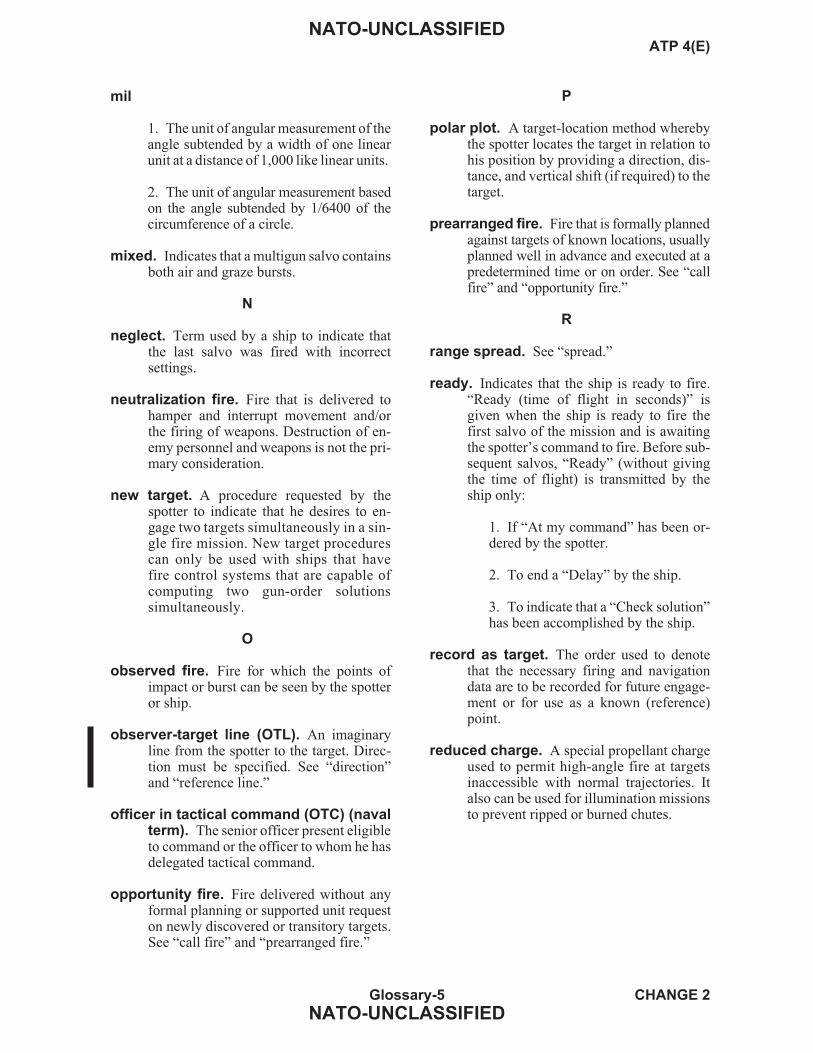
mil
1. The unit of angular measurement of theangle subtended by a width of one linearunit at a distance of 1,000 like linear units.
2. The unit of angular measurement basedon the angle subtended by 1/6400 of thecircumference of a circle.
mixed. Indicates that a multigun salvo containsboth air and graze bursts.
N
neglect. Term used by a ship to indicate thatthe last salvo was fired with incorrectsettings.
neutralization fire. Fire that is delivered tohamper and interrupt movement and/orthe firing of weapons. Destruction of en-emy personnel and weapons is not the pri-mary consideration.
new target. A procedure requested by thespotter to indicate that he desires to en-gage two targets simultaneously in a sin-gle fire mission. New target procedurescan only be used with ships that havefire control systems that are capable ofcomputing two gun-order solutionssimultaneously.
O
observed fire. Fire for which the points ofimpact or burst can be seen by the spotteror ship.
observer-target line (OTL). An imaginaryline from the spotter to the target. Direc-tion must be specified. See “direction”and “reference line.”
officer in tactical command (OTC) (navalterm). The senior officer present eligibleto command or the officer to whom he hasdelegated tactical command.
opportunity fire. Fire delivered without anyformal planning or supported unit requeston newly discovered or transitory targets.See “call fire” and “prearranged fire.”
P
polar plot. A target-location method wherebythe spotter locates the target in relation tohis position by providing a direction, dis-tance, and vertical shift (if required) to thetarget.
prearranged fire. Fire that is formally plannedagainst targets of known locations, usuallyplanned well in advance and executed at apredetermined time or on order. See “callfire” and “opportunity fire.”
R
range spread. See “spread.”
ready. Indicates that the ship is ready to fire.“Ready (time of flight in seconds)” isgiven when the ship is ready to fire thefirst salvo of the mission and is awaitingthe spotter’s command to fire. Before sub-sequent salvos, “Ready” (without givingthe time of flight) is transmitted by theship only:
1. If “At my command” has been or-dered by the spotter.
2. To end a “Delay” by the ship.
3. To indicate that a “Check solution”has been accomplished by the ship.
record as target. The order used to denotethat the necessary firing and navigationdata are to be recorded for future engage-ment or for use as a known (reference)point.
reduced charge. A special propellant chargeused to permit high-angle fire at targetsinaccessible with normal trajectories. Italso can be used for illumination missionsto prevent ripped or burned chutes.
Glossary-5 CHANGE 2
NATO-UNCLASSIFIED
NATO-UNCLASSIFIEDATP 4(E)
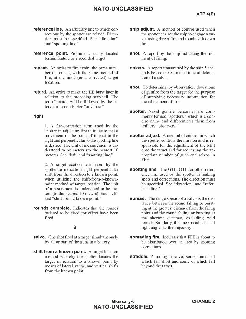
reference line. An arbitrary line to which cor-rections by the spotter are related. Direc-tion must be specified. See “direction”and “spotting line.”
reference point. Prominent, easily locatedterrain feature or a recorded target.
repeat. An order to fire again, the same num-ber of rounds, with the same method offire, at the same (or a corrected) targetlocation.
retard. An order to make the HE burst later inrelation to the preceding starshell. Theterm “retard” will be followed by the in-terval in seconds. See “advance.”
right
1. A fire-correction term used by thespotter in adjusting fire to indicate that amovement of the point of impact to theright and perpendicular to the spotting lineis desired. The unit of measurement is un-derstood to be meters (to the nearest 10meters). See “left” and “spotting line.”
2. A target-location term used by thespotter to indicate a right perpendicularshift from the direction to a known point,when utilizing the shift-from-a-known-point method of target location. The unitof measurement is understood to be me-ters (to the nearest 10 meters). See “left”and “shift from a known point.”
rounds complete. Indicates that the roundsordered to be fired for effect have beenfired.
S
salvo. One shot fired at a target simultaneouslyby all or part of the guns in a battery.
shift from a known point. A target locationmethod whereby the spotter locates thetarget in relation to a known point bymeans of lateral, range, and vertical shiftsfrom the known point.
ship adjust. A method of control used whenthe spotter desires the ship to engage a tar-get using direct fire and to adjust its ownfire.
shot. A report by the ship indicating the mo-ment of firing.
splash. A report transmitted by the ship 5 sec-onds before the estimated time of detona-tion of a salvo.
spot. To determine, by observation, deviationsof gunfire from the target for the purposeof supplying necessary information forthe adjustment of fire.
spotter. Naval gunfire personnel are com-monly termed “spotters,” which is a con-cise name and differentiates them fromartillery “observers.”
spotter adjust. A method of control in whichthe spotter controls the mission and is re-sponsible for the adjustment of the MPIonto the target and for requesting the ap-propriate number of guns and salvos inFFE.
spotting line. The GTL, OTL, or other refer-ence line used by the spotter in makingspots and corrections. The direction mustbe specified. See “direction” and “refer-ence line.”
spread. The range spread of a salvo is the dis-tance between the round falling or burst-ing at the greatest distance from the firingpoint and the round falling or bursting atthe shortest distance, excluding wildrounds. Similarly, the line spread is that atright angles to the trajectory.
spreading fire. Indicates that FFE is about tobe distributed over an area by spottingcorrections.
straddle. A multigun salvo, some rounds ofwhich fall short and some of which fallbeyond the target.
Glossary-6 CHANGE 2
NATO-UNCLASSIFIED
NATO-UNCLASSIFIEDATP 4(E)
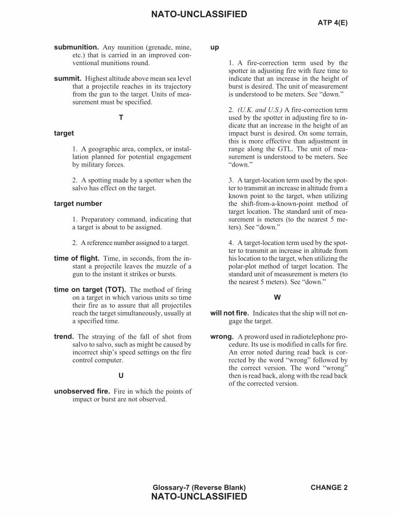
submunition. Any munition (grenade, mine,etc.) that is carried in an improved con-ventional munitions round.
summit. Highest altitude above mean sea levelthat a projectile reaches in its trajectoryfrom the gun to the target. Units of mea-surement must be specified.
T
target
1. A geographic area, complex, or instal-lation planned for potential engagementby military forces.
2. A spotting made by a spotter when thesalvo has effect on the target.
target number
1. Preparatory command, indicating thata target is about to be assigned.
2. A reference number assigned to a target.
time of flight. Time, in seconds, from the in-stant a projectile leaves the muzzle of agun to the instant it strikes or bursts.
time on target (TOT). The method of firingon a target in which various units so timetheir fire as to assure that all projectilesreach the target simultaneously, usually ata specified time.
trend. The straying of the fall of shot fromsalvo to salvo, such as might be caused byincorrect ship’s speed settings on the firecontrol computer.
U
unobserved fire. Fire in which the points ofimpact or burst are not observed.
up
1. A fire-correction term used by thespotter in adjusting fire with fuze time toindicate that an increase in the height ofburst is desired. The unit of measurementis understood to be meters. See “down.”
2. (U.K. and U.S.) A fire-correction termused by the spotter in adjusting fire to in-dicate that an increase in the height of animpact burst is desired. On some terrain,this is more effective than adjustment inrange along the GTL. The unit of mea-surement is understood to be meters. See“down.”
3. A target-location term used by the spot-ter to transmit an increase in altitude from aknown point to the target, when utilizingthe shift-from-a-known-point method oftarget location. The standard unit of mea-surement is meters (to the nearest 5 me-ters). See “down.”
4. A target-location term used by the spot-ter to transmit an increase in altitude fromhis location to the target, when utilizing thepolar-plot method of target location. Thestandard unit of measurement is meters (tothe nearest 5 meters). See “down.”
W
will not fire. Indicates that the ship will not en-gage the target.
wrong. A proword used in radiotelephone pro-cedure. Its use is modified in calls for fire.An error noted during read back is cor-rected by the word “wrong” followed bythe correct version. The word “wrong”then is read back, along with the read backof the corrected version.
Glossary-7 (Reverse Blank) CHANGE 2
NATO-UNCLASSIFIED
NATO-UNCLASSIFIEDATP 4(E)

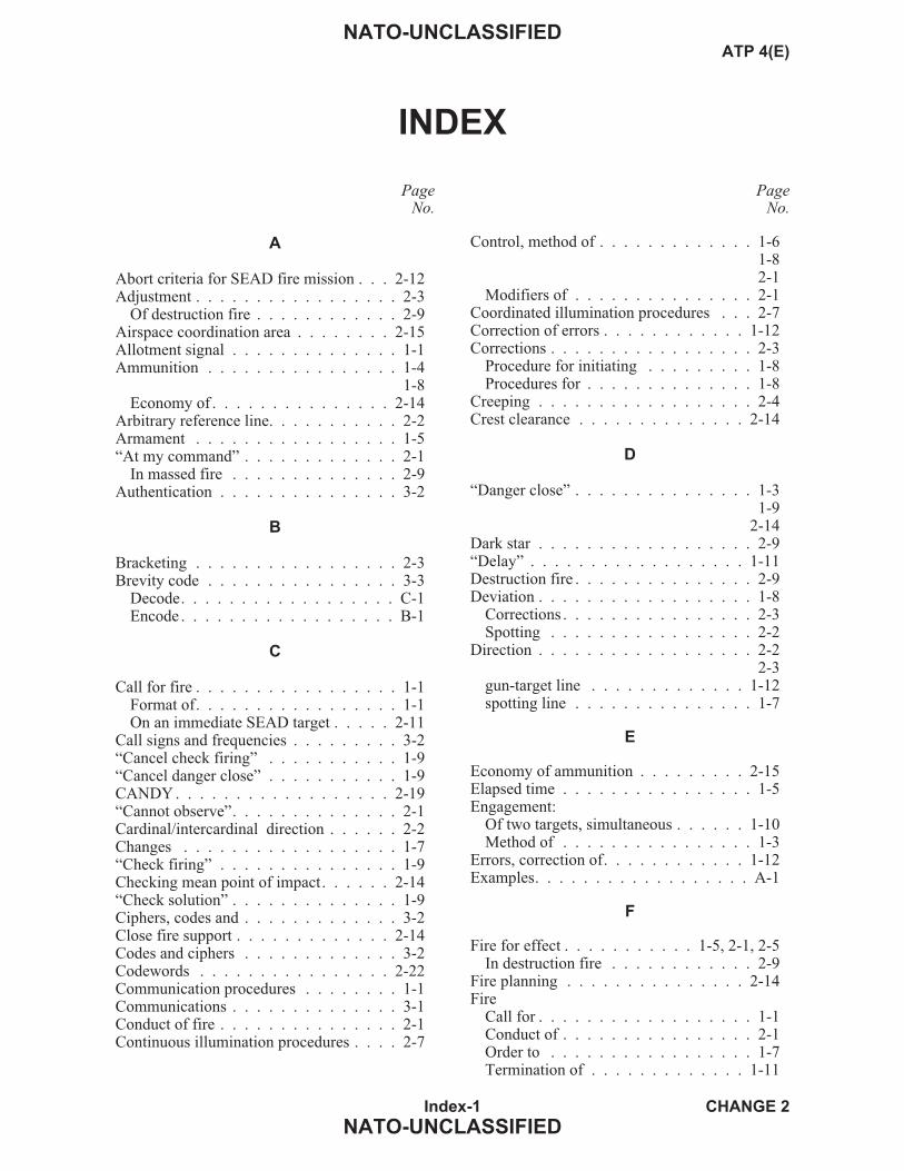
INDEX
PageNo.
A
Abort criteria for SEAD fire mission . . . 2-12Adjustment . . . . . . . . . . . . . . . . . 2-3
Of destruction fire . . . . . . . . . . . . 2-9Airspace coordination area . . . . . . . . 2-15Allotment signal . . . . . . . . . . . . . . 1-1Ammunition . . . . . . . . . . . . . . . . 1-4
1-8Economy of . . . . . . . . . . . . . . . 2-14
Arbitrary reference line. . . . . . . . . . . 2-2Armament . . . . . . . . . . . . . . . . . 1-5“At my command” . . . . . . . . . . . . . 2-1
In massed fire . . . . . . . . . . . . . . 2-9Authentication . . . . . . . . . . . . . . . 3-2
B
Bracketing . . . . . . . . . . . . . . . . . 2-3Brevity code . . . . . . . . . . . . . . . . 3-3
Decode. . . . . . . . . . . . . . . . . . C-1Encode . . . . . . . . . . . . . . . . . . B-1
C
Call for fire . . . . . . . . . . . . . . . . . 1-1Format of. . . . . . . . . . . . . . . . . 1-1On an immediate SEAD target . . . . . 2-11
Call signs and frequencies . . . . . . . . . 3-2“Cancel check firing” . . . . . . . . . . . 1-9“Cancel danger close” . . . . . . . . . . . 1-9CANDY . . . . . . . . . . . . . . . . . . 2-19“Cannot observe”. . . . . . . . . . . . . . 2-1Cardinal/intercardinal direction . . . . . . 2-2Changes . . . . . . . . . . . . . . . . . . 1-7“Check firing” . . . . . . . . . . . . . . . 1-9Checking mean point of impact. . . . . . 2-14“Check solution” . . . . . . . . . . . . . . 1-9Ciphers, codes and . . . . . . . . . . . . . 3-2Close fire support . . . . . . . . . . . . . 2-14Codes and ciphers . . . . . . . . . . . . . 3-2Codewords . . . . . . . . . . . . . . . . 2-22Communication procedures . . . . . . . . 1-1Communications . . . . . . . . . . . . . . 3-1Conduct of fire . . . . . . . . . . . . . . . 2-1Continuous illumination procedures . . . . 2-7
PageNo.
Control, method of . . . . . . . . . . . . . 1-61-82-1
Modifiers of . . . . . . . . . . . . . . . 2-1Coordinated illumination procedures . . . 2-7Correction of errors . . . . . . . . . . . . 1-12Corrections . . . . . . . . . . . . . . . . . 2-3
Procedure for initiating . . . . . . . . . 1-8Procedures for . . . . . . . . . . . . . . 1-8
Creeping . . . . . . . . . . . . . . . . . . 2-4Crest clearance . . . . . . . . . . . . . . 2-14
D
“Danger close” . . . . . . . . . . . . . . . 1-31-9
2-14Dark star . . . . . . . . . . . . . . . . . . 2-9“Delay” . . . . . . . . . . . . . . . . . . 1-11Destruction fire . . . . . . . . . . . . . . . 2-9Deviation . . . . . . . . . . . . . . . . . . 1-8
Corrections . . . . . . . . . . . . . . . . 2-3Spotting . . . . . . . . . . . . . . . . . 2-2
Direction . . . . . . . . . . . . . . . . . . 2-22-3
gun-target line . . . . . . . . . . . . . 1-12spotting line . . . . . . . . . . . . . . . 1-7
E
Economy of ammunition . . . . . . . . . 2-15Elapsed time . . . . . . . . . . . . . . . . 1-5Engagement:
Of two targets, simultaneous . . . . . . 1-10Method of . . . . . . . . . . . . . . . . 1-3
Errors, correction of. . . . . . . . . . . . 1-12Examples. . . . . . . . . . . . . . . . . . A-1
F
Fire for effect . . . . . . . . . . . 1-5, 2-1, 2-5In destruction fire . . . . . . . . . . . . 2-9
Fire planning . . . . . . . . . . . . . . . 2-14Fire
Call for . . . . . . . . . . . . . . . . . . 1-1Conduct of . . . . . . . . . . . . . . . . 2-1Order to . . . . . . . . . . . . . . . . . 1-7Termination of . . . . . . . . . . . . . 1-11
Index-1 CHANGE 2
NATO-UNCLASSIFIED
NATO-UNCLASSIFIEDATP 4(E)

PageNo.
Fireplan . . . . . . . . . . . . . . . . . . 2-16Firing . . . . . . . . . . . . . . . . . . . . 1-7
Reports and orders, other spotter’s . . . 1-9“First salvo at (point of aim)” . . . . . . . 1-7Format of
Call for fire. . . . . . . . . . . . . . . . 1-1Support request . . . . . . . . . . . . . 1-1
Forward observer party net. . . . . . . . . 3-1Frequencies, call signs and . . . . . . . . . 3-2
“Fresh target” . . . . . . . . . . . . . . 1-9Friendly aircraft, safety of . . . . . . . . 2-15Friendly forces, safety of . . . . . . . . . 2-14Fuzes for shore targets, recommended
projectiles and . . . . . . . . . . . . D-1
G
Grid coordinates . . . . . . . . . . . . . . 1-2Gun-target line . . . . . . . . . . . . . . . 1-7
2-2Direction of . . . . . . . . . . . . . . . 1-12
Guns, number of . . . . . . . . . . . . . . 1-5Number of . . . . . . . . . . . . . . . . 1-9
GURF . . . . . . . . . . . . . . . . . . . 2-19
H
Height of burst . . . . . . . . . . . . . . . 1-9Corrections . . . . . . . . . . . . . . . . 2-4Spotting . . . . . . . . . . . . . . . . . 2-2
HONEY . . . . . . . . . . . . . . . . . . 2-18
I
Illumination:Fire . . . . . . . . . . . . . . . . . . . . 2-6Mission reports. . . . . . . . . . . . . . 2-8Projectile malfunctions . . . . . . . . . 2-8Shells, characterisics of . . . . . . . . . 2-6
Immediate SEAD target, call for fire on . 2-11Initiating:
Corrections, procedure for . . . . . . . . 1-7On-call SEAD fire mission . . . . . . . 2-11
L
Landing Force Naval Gunfire SupportNet (HF) . . . . . . . . . . . . . . . 3-21
PageNo.
“Lost”. . . . . . . . . . . . . . . . . . . . 1-9Lost rounds, unobserved and . . . . . . . . 2-5
M
Malfunctions of illumination projectile . . 2-8Marking and suppression rounds from
same ship . . . . . . . . . . . . . . 2-11Massed fire . . . . . . . . . . . . . . . . . 2-9Mean point of impact
Checking . . . . . . . . . . . . . . . . 2-13Correcting . . . . . . . . . . . . . . . . 2-4
Method of control . . . . . . . . . . . . . 1-51-92-1
Modifiers of . . . . . . . . . . . . . . . 2-1Method of engagement . . . . . . . . . . . 1-3Modifiers of method of control. . . . . . . 2-1
N
Naval Gunfire Airspot Net . . . . . . . . . 3-1Naval Gunfire Control Net . . . . . . . . . 3-1Naval Gunfire Ground Spot Net . . . . . . 3-1Naval gunfire support nets . . . . . . . . . 3-1“Neglect” . . . . . . . . . . . . . . . . . 1-11Nets, minimum requirement for NGS . . . 3-1“New target” . . . . . . . . . . . . . . . 1-10New SEAD timing . . . . . . . . . . . . 2-13
O
Observer-target line . . . . . . . . . . . . 2-2On-call SEAD fire missions . . . . . . . 2-10One-round adjustment . . . . . . . . . . . 2-4Opening fire . . . . . . . . . . . . . . . . 1-6
Reports on . . . . . . . . . . . . . . . . 1-7Operational constraints . . . . . . . . . . 2-14Order to fire . . . . . . . . . . . . . . . . 1-7Orders
Firing reports and . . . . . . . . . . . . 1-7Other spotter’s firing reports and . . . . 1-8Ship’s reports and. . . . . . . . . . . . 1-11
Originator of request . . . . . . . . . . . . 1-1Other spotter’s firing reports and orders . . 1-9
P
Passage of requests . . . . . . . . . . . . . 1-1PEPPER . . . . . . . . . . . . . . . . . . 2-18PICKLE . . . . . . . . . . . . . . . . . . 2-19
Index-2 CHANGE 2
NATO-UNCLASSIFIED
NATO-UNCLASSIFIEDATP 4(E)

PageNo.
Planned SEAD fires. . . . . . . . . . . . 2-10Polar plot . . . . . . . . . . . . . . . . . . 1-3Precedence . . . . . . . . . . . . . . . . . 3-2Prefiring . . . . . . . . . . . . . . . . . . 1-1
Report . . . . . . . . . . . . . . . . . . 1-7Reports for SEAD fire . . . . . . . . . 2-13
Procedures forCommunciations . . . . . . . . . . . . . 3-2Corrections . . . . . . . . . . . . . . . . 1-8
Projectiles and fuzes for shore targets,recommended . . . . . . . . . . . . D-1
R
Radiotelegraph procedures . . . . . . . . . 3-2Range . . . . . . . . . . . . . . . . . . . . 1-9
Corrections . . . . . . . . . . . . . . . . 2-3Spotting . . . . . . . . . . . . . . . . . 2-2
“Ready”. . . . . . . . . . . . . . . . . . . 1-7“Record as target” . . . . . . . . . . . . . 1-9“Repeat” . . . . . . . . . . . . . . . . . . 1-9Reports
And orders, firing . . . . . . . . . . . . 1-8And orders, ship’s . . . . . . . . . . . 1-11And returns . . . . . . . . . . . . . . . 2-18On opening fire . . . . . . . . . . . . . 1-7Illumination mission . . . . . . . . . . . 2-8
Request for support. . . . . . . . . . . . . 1-1Ripped chutes . . . . . . . . . . . . . . . 2-8“Rounds complete” . . . . . . . . . . . . 1-12
S
Safe correction . . . . . . . . . . . . . . 2-14Safety . . . . . . . . . . . . . . . . . . . 2-12
Of friendly aircraft . . . . . . . . . . . 2-14Salvos, number of . . . . . . . . . . . . . 1-5
1-8Scheduled SEAD fire missions . . . . . . 2-10Selection of spotting line . . . . . . . . . . 2-2Shift from known point. . . . . . . . . . . 1-3“Ship adjust” . . . . . . . . . . . . . . . . 1-6
2-1Ship, termination of fire by . . . . . . . . 1-11Ship’s reports and orders . . . . . . . . . 1-11Shore fire control party local net . . . . . . 3-2Simultaneous engagement of two targets . . 1-10
PageNo.
Special instructions. . . . . . . . . . . . . 1-5“Spotter adjust”. . . . . . . . . . . . . . . 1-6
2-1Spotter identification . . . . . . . . . . . . 1-2Spotter, termination of fire by . . . . . . 1-12Spotting. . . . . . . . . . . . . . . . . . . 2-2Spotting line
Direction of . . . . . . . . . . . . . . . 1-7Selection of . . . . . . . . . . . . . . . 2-1
“Spreading fire” . . . . . . . . . . . . . . 1-10“Straddle” . . . . . . . . . . . . . . . . . 1-10Summit . . . . . . . . . . . . . . . . . . . 1-7
1-12Support, request for . . . . . . . . . . . . 1-1Suppression of enemy air defense (SEAD)
fire missions. . . . . . . . . . . . . 2-10Suppression rounds from same ship,
marking and . . . . . . . . . . . . . 2-11Surveillance . . . . . . . . . . . . . . . . 2-5Synchronized clock. . . . . . . . . . . . . 1-5
T
TargetClassification and priority . . . . . . . 2-16Description . . . . . . . . . . . . . . . . 1-3Lists. . . . . . . . . . . . . . . . . . . 2-16Location . . . . . . . . . . . . . . . . . 1-2Number, warning order and . . . . . . . 1-2Numbers . . . . . . . . . . . . . . . . 2-16
Termination of fire . . . . . . . . . . . . 1-11Time of flight . . . . . . . . . . . . . . . 1-12Time on target . . . . . . . . . . . . . . . 1-5Trajectory. . . . . . . . . . . . . . . . . . 1-4
1-8Transmission, correcting errors in . . . . 1-12“Trend” . . . . . . . . . . . . . . . . . . . 1-9Two targets, simultaneous engagement of . 1-11
U
Unobserved and lost rounds . . . . . . . . 2-5Uses of illumination fire . . . . . . . . . . 2-6
W
Warning order and target number . . . . . 1-2
Index-3 (Reverse Blank) CHANGE 2
NATO-UNCLASSIFIED
NATO-UNCLASSIFIEDATP 4(E)


LIST OF EFFECTIVE PAGES
LEP-1 (Reverse Blank) CHANGE 4
NATO-UNCLASSIFIED
NATO-UNCLASSIFIEDATP 4(E)
Effective Pages Page Numbers
OriginalOriginalOriginalChange 2
OriginalChange 2Change 4Change 2Change 3Change 2Change 2Change 4Change 2Change 3Change 2Change 2Change 2Change 2Change 4Change 2Change 2
Change 2
Change 4
I (Reverse Blank)III (Reverse Blank)V thru VII (Reverse Blank)Deleted pages VIIa thru VIIi(Reverse Blank)
IX, XXI thru XVII (Reverse Blank)XIX (Reverse Blank)1-1 thru 1-81-9, 1-101-11 thru 1-13 (Reverse Blank)2-1 thru 2-62-7, 2-82-9, 2-102-11 thru 2-142-15 thru 2-243-1, 3-2A-1 thru A-23 (Reverse Blank)B-1 (Reverse Blank)C-1, C-2D-1 (Reverse Blank)Glossary-1 thru Glossary-7(Reverse Blank)
Index-1 thru Index-3(Reverse Blank)
LEP-1 (Reverse Blank)


ATP 4(E)
NATO-UNCLASSIFIED
NATO-UNCLASSIFIED
Related Documents