INSTALLATION RESTORATION PROGRAM PHASE I -RECORDS SEARCH O'HARE AIR RESERVE FORCES FACILITY, ILLINOIS Prepared For UNITED STATES AIR FORCE HEADQUARTERS AIR FORCE RESERVE Robins Air Force Base, Georgia December 1983 P_' k: it LAJ Prepared By L- ENGINEER ING-SCIENCE C 57 Executive Park South, Suite 590 Atlanta, Georgia 30329 0 1 5

Welcome message from author
This document is posted to help you gain knowledge. Please leave a comment to let me know what you think about it! Share it to your friends and learn new things together.
Transcript
INSTALLATION RESTORATION PROGRAMPHASE I -RECORDS SEARCH
O'HARE AIR RESERVE FORCES FACILITY,ILLINOIS
Prepared For
UNITED STATES AIR FORCEHEADQUARTERS
AIR FORCE RESERVERobins Air Force Base, Georgia
December 1983
P_' k: it
LAJ Prepared By
L-
ENGINEER ING-SCIENCEC 57 Executive Park South, Suite 590
Atlanta, Georgia 30329 0 1 5
NOTICE
This report has been prepared for the United States AirForce by Engineering-Science for the purpose of aiding inthe Air Force Installation Restoration Program. It is notan endorsement of any product. The views expressedherein are those of the contractor and do not necessarilyreflect the official views of the publishing agency, the UnitedStates Air Force, nor the Department of Defense.
Copies of the report may be purchased from:
National Technical Information Service5285 Port Royal RoadSpringfield, Virginia 22161
Federal Government agencies and their contractorsregistered with Defense Technical Information Centershould direct requests for copies of this report to:
Defense Technical Information CenterCameron StationAlexandria, Virginia 22314
!'
I
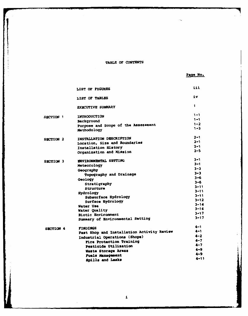
TABLE OF CONTENTS
LIST OF FIGURES iii
LIST OF TABLES iv
EXECUTIVE SUMMARY 1
SECTION 1 INTRODUCTION 1-1
Background 1-1
Purpose and Scope of the Assessment 1-2
Methodology 1-3
SECTION 2 INSTALLATION DESCRIPTION 2-1
Location, Size and Boundaries 2-1
Installation History 2-1
Organization and Mission 2-5
SECTION 3 ENVIRONMENTAL SETTING 3-1
eteorology 3-1
Geography 3-3
Topography and Drainage 3-3
Geology 3-6
Stra tigraphy 3-6
Structure 3-11
Hydrology 3-11
Subsurface Hydrology 3-11
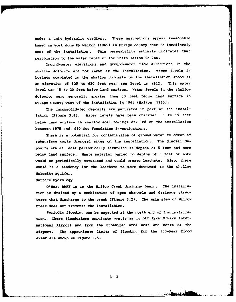
Surface Hydrology 3-12
Water Use 3-14
Water Quality 3-14
Biotic Environment 3-17
Summary of Environmental Setting 3-17
SUCTION 4 FINDINGS 4-1
Past Shop and Installation Activity Review 4-1
industrial Operations (Shops) 4-2
Fire Protection Training 4-7
Pesticide Utilization 4-7
Waste Storage Areas 4-9
Fuels Management 4-9Spills and Leaks 4-11
£
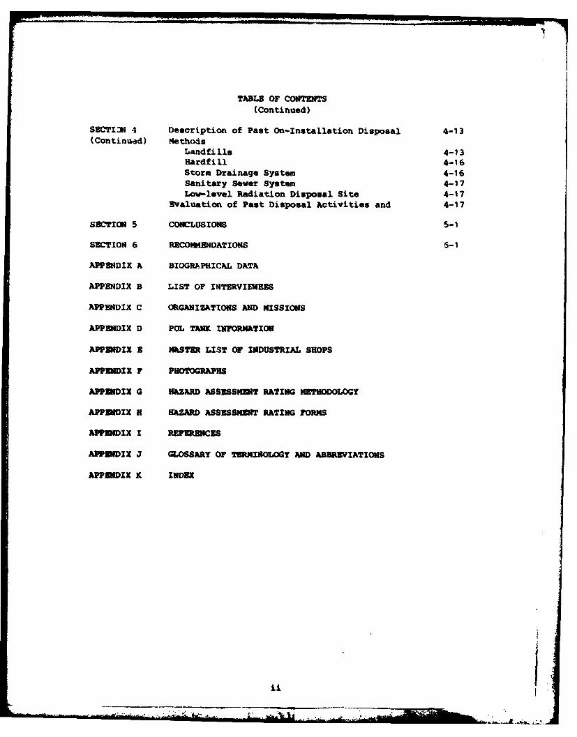
TABLE OF CONTENTS(Continued)
SECTION 4 Description of Past On-Installation Disposal 4-1 3(Continued) Methods
Landfills 4-13
Hardfi 11 4-16Storm Drainage System 4-16Sanitary Sewer System 4-17Low-level Radiation Disposal Site 4-17
Evaluation of Past Disposal Activities and 4-17
SECTION 5 CONCLUSIONS 5-1
SECTION 6 RECOMMENDATIONS 6-1
APPENDIX A BIOGRAPHICAL DATA
APPENDIX B LIST OF INTERVIEWEES
APPENDIX C ORGANIZATIONS AND MISSIONS
APPENDIX D POL TANK INFORNATION
APPIDIX B MASTER LIST OF INDUSTRIAL SHOPS
APPENDIX F PHOTOGRAPHS
APPUIDIX G HAZARD ASSESSNRlT RATING METHODOLOGY
APPENDIX H HAZARD ASSESSMENT RATING FORMS
APPENDIX I REFERENCES
APPIDIX J GLOSSARY OF TERMINOLOGY AND ABBREVIATIONS
APPUIDIX K INDEX
I
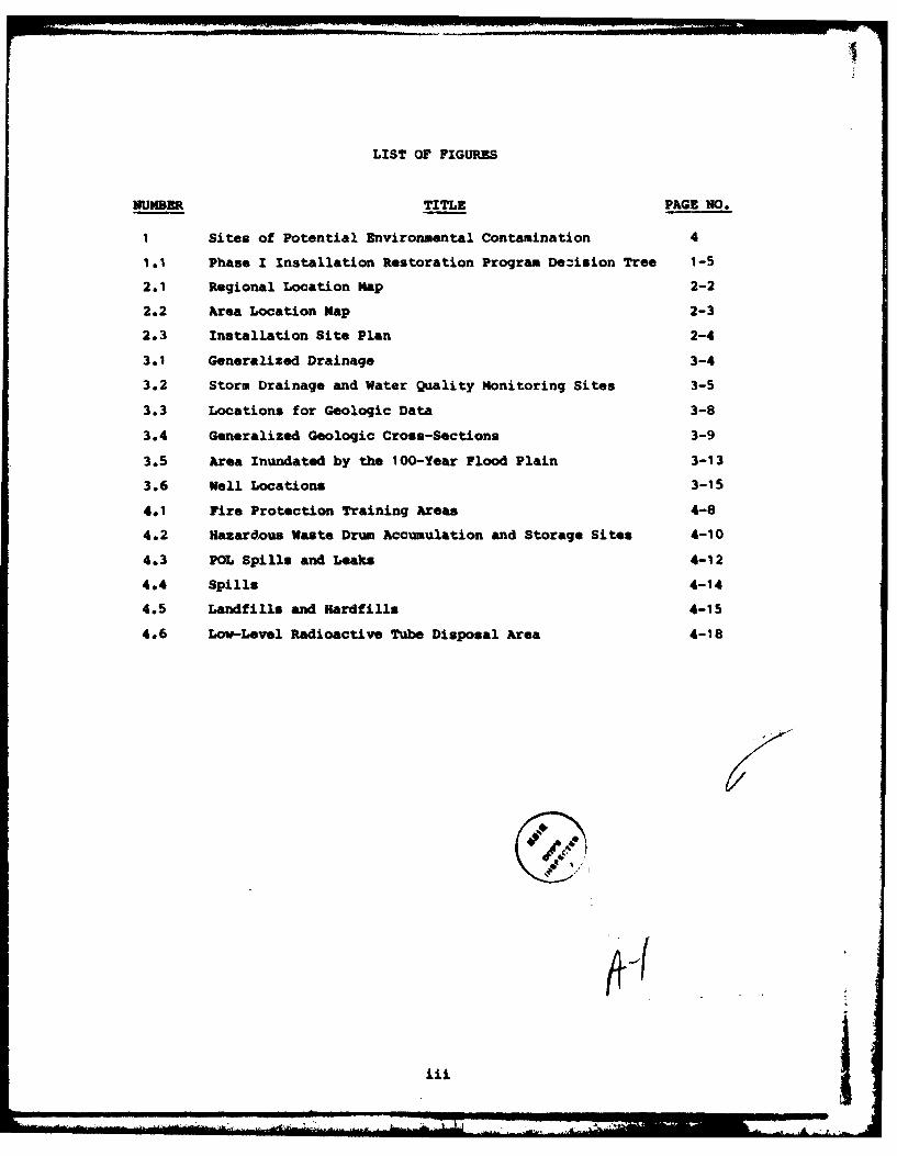
LIST OF FIGURES
NUMBER TITLE PAGE NO.
1 Sites of Potential Environmental Contamination 4
I.I Phase I Installation Restoration Program Deision Tree 1-5
2.1 Regional Location Map 2-2
2.2 Area Location Map 2-3
2.3 Installation Site Plan 2-4
3.1 Generalized Drainage 3-4
3.2 Storm Drainage and Water Quality Monitoring Sites 3-5
3.3 Locations for Geologic Data 3-8
3.4 Generalized Geologic Cross-Sections 3-9
3.5 Area Inundated by the 100-Year Flood Plain 3-13
3.6 Well Locations 3-15
4.1 Fire Protection Training Areas 4-8
4.2 Hazardous Waste Drum Accumulation and Storage Sites 4-10
4.3 POL Spills and Leaks 4-12
4.4 Spills 4-14
4.5 Landfills and ardfills 4-15
4.6 Low-Level Radioactive Tube Disposal Area 4-18
/1
lii
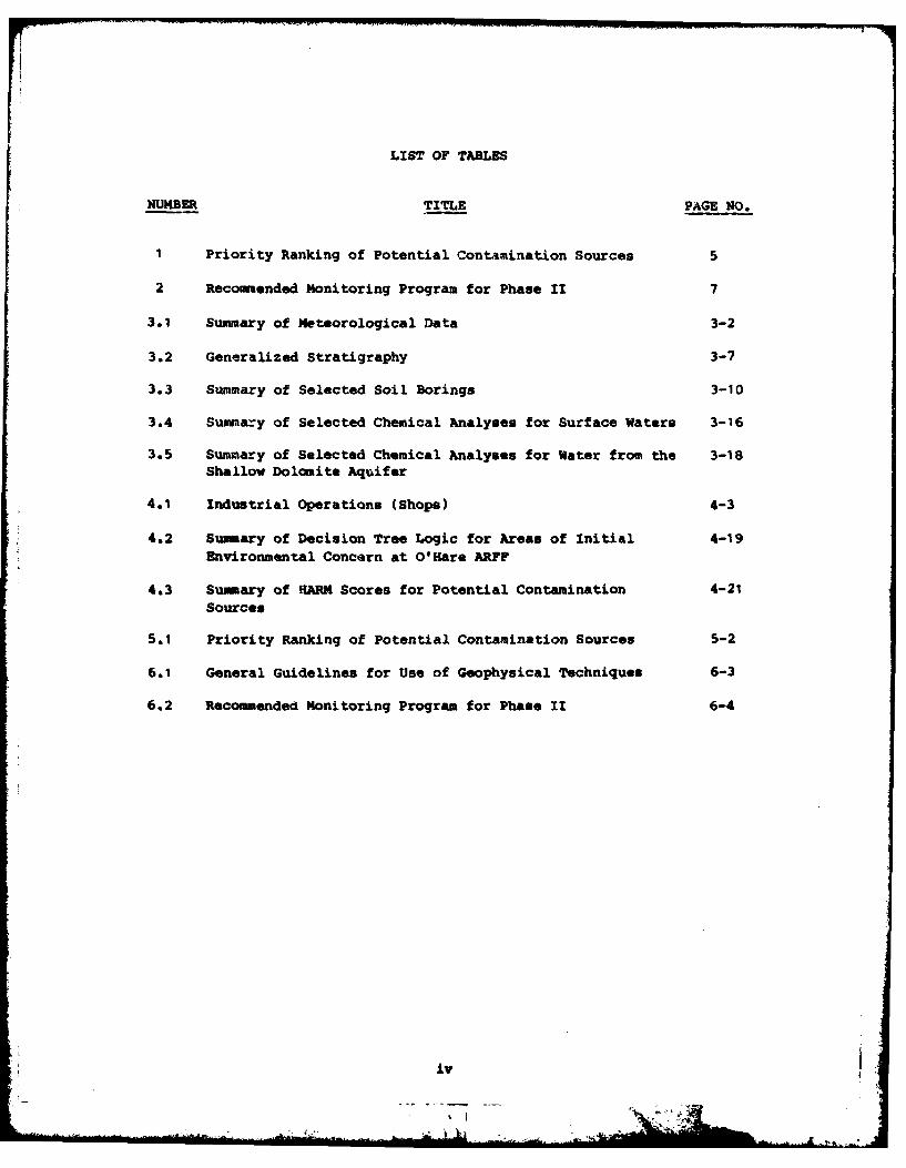
LIST OF TABLES
NUMBER TITLE PAGE NO.
1 Priority Ranking of Potential Contamination Sources 5
2 Recommended Monitoring Program for Phase II 7
3.1 Summary of Meteorological Data 3-2
3.2 Generalized Stratigraphy 3-7
3.3 Summary of Selected Soil Borings 3-10
3.4 Summary of Selected Chemical Analyses for Surface Waters 3-16
3.5 Summary of Selected Chemical Analyses for Water from the 3-18Shallow Dolomite Aquifer
4.1 Industrial Operations (Shops) 4-3
4.2 Summary of Decision Tree Logic for Areas of Initial 4-19Environmental Concern at O'Hare ARFF
4.3 Summary of HARM Scores for Potential Contamination 4-21Sources
5.1 Priority Ranking of Potential Contamination Sources 5-2
6.1 General Guidelines for Use of Geophysical Techniques 6-3
6.2 Recommended Monitoring Program for Phase II 6-4
iy
EXECUTIVE SUH1ARY
The Department of Defense (DOD) has developed a program to identify
and evaluate past hazardous material disposal sites on DOD property, to
control the migration of hazardous contaminants, and to control hazards
to health or welfare that may result from these past disposal opera-
tions. This program is called the Installation Restoration Program
(IRP). The IRP has four phases consisting of Phase 1, Initial Assess-
ment/Records Search; Phase II, Confirmation and Quantification; Phase
III, Technology Base Develoymentl and Phase IV, OFerations/Remedial
Actions. Engineering-Science (ES) was retained by --!e United States Air
Fore1 to conduct the Phase 1, Initial Arsessment/Records Search for
O'are Air Reserve Forces Facility (hAFF) under Contract No. F08637-80-
R0009.
INSTALLATION DESCRIPTIOE
7The O'Hare Air Reserve Forces Facility complex at O'Hare Inter-
national Airport is located in the Chicago metropolitan area in north-
eastern Illinois. The airport is located northwest of downtown Chicago
at the boundary of Cook County and DuPage County. All of the property
around the airport and Air Force installation is urbanized and used for
residential, comercial and/or industrial purposes .The military 7
portion of O'Hare Airport is composed of approximately 400 acres of land
in the northwest corner of the airport.
Initially called Orchard Place Airport, the site was activated in
October of 1942, when the government acquired a number of tracts of farm
land. The War Assets Corporation erected buildings on this land and
leased it in June, 1943, to Douglas Aircraft Company as an assembly
plant for the C-54 cargo aircraft. The plant was closed in the fall of
1945.
In 1946, the site was reactivated as a military installation when
the 803rd Army Air Force Reserve Specialized Depot assumed control of
the site. In 1949, the military portion was redesignated USAF O'Hare
Field, Chicago International Airport. In 1970 the Lockheed C-130A
"Hercules" arrived. The 928th Tactical Airlift Group is still the
installation's host unit.
ENVIRONMENTAL SETTING
The environmental setting data reviewed for this investLgation
identified the following major points that are relevant to O'Hare ARFF.
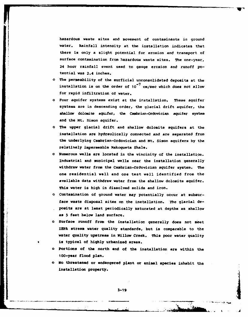
o Net precipitation at the installation is 4.2 inches which in-
dicates that there is some potential for leachate generation at
hazardous waste sites and movement of contaminants in ground
water. Rainfall intensity at the installation indicates that
there is only a slight potential for erosion and transport of
surface contamination from hazardous waste sites. The one-year,
24 hour rainfall event used to gauge erosion and runoff po-
tential was 2.4 inches.
o The permeability of the surficial unconsolidated deposits at the
installation is on the order of 10- 7 cm/sec which does not allow
for rapid infiltration of water.
o Four aquifer systems exist at the installation. These aquifer
systems are in descending order, the glacial drift aquifer, the
shallow dolomits aquifer, the Cabrian-Ordovician aquifer system
and the Mt. Simon aquifer.
o The upper glacial drift and shallow dolomite aquifers at the
installation are hydraulically connected and are separated from
the underlying Cambrian-Ordovician and Mt. Simon aquifers by the
relatively impermeable Makoqueta Shale.
o Numerous wells are located in the vicinity of the installation.
Industrial and municipal wells near the installation generally
withdraw water from the Cambrian-Ordovician aquifer system. One
residential well and one test well identified from the available
data withdraw water from the shallow dolomite aquifer. This
water is high in dissolved solids and iron.
o Contamination of ground water may potentially occur at subsur-
face waste disposal sites on the installation. The glacial
-2-
LA
deposits are at least periodically saturated at depths as
shallow as 5 feet below land surface.
o Surface runoff from the installation generally does not meet
IEPA stream water quality standards, but is comparable to the
water quality upstream in Willow Creek. This poor water quality
is typical of highly urbanized areas.
o Portions of the north end of the installation are within the
100-year flood plan.
o No threatened or endangered plant or animal species inhabit the
installation property.
METHODOLOGY
During the course of this project, interviews were conducted with
installation personnel (past and present) familiar with past waste
disposal practices; file searches were performed for past hazardous
waste activities, interviews were held with local, state and federal
agencies; and field and aerial surveys were conducted at suspected pasthazardous waste activity sites. Eleven sites located within O'Hare ARFF
boundaries were identified as potentially containing hazardous contami-
nants and having the potential for migration resulting from past acti-
vities (Figure I). These sites have been assessed using a Hazard
Assessment Rating Methodology (HARM) which takes into account factors
such as site characteristics, waste characteristics, potential for
contaminant migration and waste management practices. The details of
the rating procedure are presented in Appendix G and the results of the
assessment are given in Table 1. The rating system is designed to
indicate the relative need for follow-on investigation.
FINDINGS AND CONCLUSIONS
The following conclusions have been developed installationd on the
results of the project team's field inspection, review of installationrecords and files, and interviews with installation personnel.
L Nine areas were determined to have a sufficient potential for
environmental contamination to warrant further investigaton. They are
as follows:
-3-
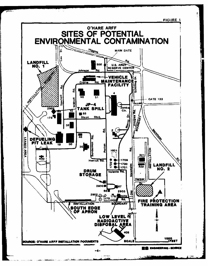
FIGUJRE I
O'HARE ARF
SITES OF POTENTIALENVIRONMENTAL CONTAMINATION
LANDFILLNO. 1 5 EEV E
Crome Rd. MAINTENANCE
C,--
(290 TANK SPILL Qemko
V 2 0
:r, DEFUELING
00 z100001M ~ ~ ~ 0 ARP ISL0AIO OUET CAE FE
4 cESNEm-cic
-321
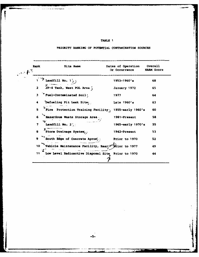
TABLE I
PRIORITY RANKING OF POTENTIAL CONTAMINATION SOURCES
Rank Site Name Dates of Operation OverallOr Occurrence HARM Score
1- Landfill No. I 1953-1960's 68
2 JP-4 Tank, West POL Area January 1972 65
3 Fuel-Contaminated Soil, 1977 64
4 -befueling Pit Leak Site-, Late 1960's 63
5 Fire Protection Training Facility) 1955-early 1960's 60
6 Hazardous Waste Storage Area- 1981-Present 58
7 Landfill No. 2", 1965-early 1970's 55
8 Storm Drainage System,, 1942-Present 53
9 South Edge of Concrete Apron ) Prior to 1970 52
10 Vehicle Maintenance Facility, Rear- ior to 1977 49
11 Low Level Radioactive Disposal Site Prior to 1970 44
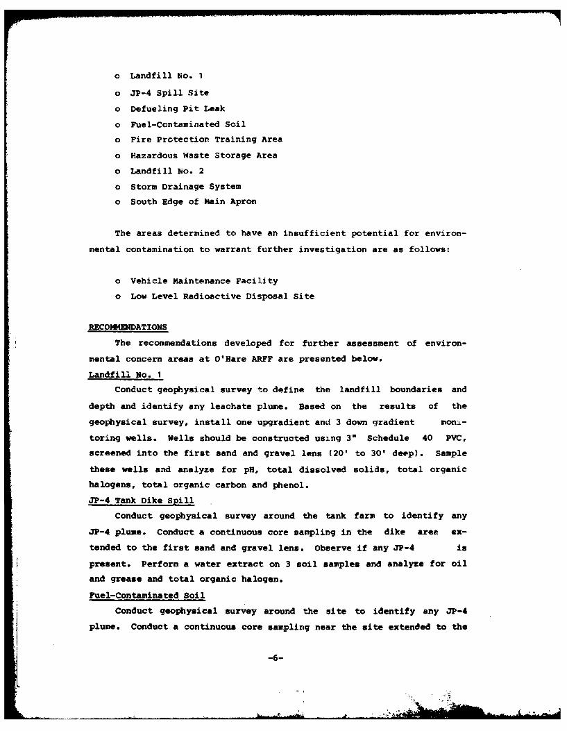
o Landfill No. 1
o JP-4 Spill Site
o Defueling Pit Leak
o Fuel-Contaminated Soil
o Fire Protection Training Area
o Hazardous Waste Storage Area
o Landfill No. 2
o Storm Drainage System
o South Edge of Main Apron
The areas determined to have an insufficient potential for environ-
mental contamination to warrant further investigation are as follows:
o Vehicle Maintenance Facility
o Low Level Radioactive Disposal Site
RECOMMENDATIONS
The recommendations developed for further assessment of environ-
mental concern areas at O'Hare ARFF are presented below.
Landfill No. 1
Conduct geophysical survey to define the landfill boundaries and
depth and identify any leachate plume. Based on the results of the
geophysical survey, install one upgradient and 3 down gradient mon-
toring wells. Wells should be constructed using 3" Schedule 40 PVC,
screened into the first sand and gravel lens (20' to 30' deep). Sample
these wells and analyze for pH, total dissolved solids, total organic
halogens, total organic carbon and phenol.
JP-4 Tank Dike Spill
Conduct geophysical survey around the tank farm to identify any
JP-4 plume. Conduct a continuous core sampling in the dike area ex-
tended to the first sand and gravel lens. Observe if any JP-4 is
present. Perform a water extract on 3 soil samples and analyze for oil
and grease and total organic halogen.
Fuel-Contaminated Soil
Conduct geophysical survey around the site to identify any JP-4
plume. Conduct a continuous core sampling near the site extended to the
-6-
first sand and gravel lens (20'-30' deep). Observe if any JP-4 is pre-
sent. Perform a water extract on 3 soils samples and analyze for oil
and grease, and total organic carbon.
Defueling Pit Leak Site
Conduct geophysical survey around the site to identify any JP-4
plume. Conduct a continuous core sampling near the site extended to the
first sand and gravel lens (20'-301 deep). Observe if any JP-4 is
present. Perform a water extract on 3 soil samples and analyze for oil
and grease, and total organic carbon.
Fire Protection Training Area
Conduct geophysical survey around the site to identify any leachate
plume.
Hazardous Waste Storage Area
Conduct a continuous core sampling in the center of the site ex-
tended to the first sand and gravel lens (20'-30' deep). Observe if
contamination present. Perform a water extract of 3 selected soil
samples (in contaminated zones if present) and perform analyses for pH,
total organic halogen and total organic carbon.
Landfill No. 2
Conduct geophysical survey to define the landfill boundaries and
depth and identify any leachate plume. Based on the results of the geo-
physical survey, install one upgradient and two downgradient monitoring
wells. Wells should be constructed of 3" Schedule 40 PVC, screened into
the first sand and gravel lens (20'-30' deep). Sample these wells and
analyze for pH, total organic carbon, total organic halogen, total
dissolved solids and phenols.
Storm Drainage System Near Hangars
Conduct continuous core sample at the nearest wooden pipe section
and at the nearest outfall extended to the first sand and gravel lens.
Observe if contamination is present. Perform a water extraction of 3
samples and analyze for total organic halogen, total organic carbon and
pR.
Svills along South Edge of Main Apron
Conduct a continuous core sampling at the edge of the apron ex-
tended to the first sand and gravel lens (20'-30' deep). Observe if any
contamination present. Perform a water extract on 3 selected soil
t -7-
samples (in contaminated zones if present) and perform analyses for p1,
total organic halogen and total organic carbon.
-8-
SECTION 1
INTRODUCTION
BACKGROUND
The United States Air Force, due to its primary mission, has long
been engaged in a wide variety of operations dealing with toxic and
hazardous materials. Federal, state, and local governments have devel-
oped strict regulations to require that disposers identify the locations
and contents of past disposal sites and take action to eliminate hazards
in an environmentally responsible manner. The primary Federal legisla-
tion governing"disposal of hazardous waste is the Resource Conservation
and Recovery Act (RCRA) of 1976, as amended. Under Section 6003 of the
Act, Federal agencies are directed to assist the Environmental Protec-
tion Agency (EPA) and under Section 3012, state agencies are required to
inventory past disposal sites and make the information available to the
requesting agencies. To assure compliance with these hazardous waste
regulations, the Department of Defense (DOD) developed the Installation
Restoration Trogram (IRP). The current DOD IRP policy is contained in
Defense Environmental Quality Program Policy Memorandum (DEQPPM) 81-5,
dated 11 December 1981 and implemented by Air Force message dated 21
January 1982. DEQPPM 81-5 reissued and amplified all previous direc-
tives and memoranda on the Installation Restoration Program. DOD policy
is to identify and fully evaluate suspected problems associated with
past hazardous contamination, and to control hazards to health and wel-
fare that resulted from these past operations. The IRP will be the
basis for response actions on Air Force installations under the provi-
sions of the Comprehensive Environmental Response, Compensation, and
Liabilty Act (C3RCLA) of 1980, and clarified by Executive Order 12316.
1-1
PURPOSE AND SCOPE OF THE ASSESSMNT
The installation Restoration Program has been developed as a four-
phased program as follows:
Phase I - Initial Assessment/Records Search
Phase II - Confirmation and Quantification
Phase III - Technology installation Development
Phase IV - Operations/Remedial Actions
Engineering-Science (ES) was retained by the United States Air
Force to conduct the Phase I Records Search at O'Hare Air Reserve Forces
Facility (kPRFF), Contract No. F08637-80-R0009. This report contains a
summary and an evaluation of the information collected during Phase I of
the IRP and recommendations for follow on actions.
The goal of the first phase of the program was to identify the
potential for environmental conLamination from past waste lisposal
practices at O'Hare ARFF, and to assess the potential for contaminant
migration. The activities that were performed in the Phase I study
included the following:
- Review of knstallation records
- Interview of personnel familiar with past generation and dis-
posal activities
- Survey of wastes
- Determination of estimated quantities and locations of current
and past hazardous waste treatment, storage, and disposal
- Definition of the environmental setting at the installation
- Review of past disposal practices and methods
- Field inspection of installation facilities
- Collection of pertinent information from Federal, state and
local agencies
- Assessment of potential for contaminant migration
- Development of follow-on recommendations.
1-2
ES performed the on-site portion of the records search durAg
August 1983. The following team of professionals were involved:
- D. L. Gregory, Environmental Engineer and Project Manager, NSCE,
5 years of professional experience
- H. D. Harmon, Hydrogeologist, 9 years of professional experience
- R. 3. Reimer, Chemical Engineer, 4 years of professional experi-
ence
more detailed information on these three individuals is presented in
Appendix A.
METHODOLOGY
The methodology utilized in the O'Hare ARFF Records Search began
with a review of past and present industrial operations conducted at the
installation. Information was obtained from available records and
files, as well as interviews with past and present installation
employees from the various operating areas. Those interviewed included
- current and past personnel associated with Civil Engineering,
Consolidated Aircraft Maintenance, Base Supply, and the Base Clinic. A
listing of the installation interviewees by position and approximate
years of service is presented in Appendix B.
Concurrent with the installation interviews, the applicable
Federal, state and local agencies were contacted for pertinent instal-
lation-related environmental data. The agencies contacted and inter-
viewed are listed below and additional information is included in
Appendix B.
o U.S. Environmental Protection Agency (EPA), Region V
o U.S. Geological Survey (USGS), Water Resources Division
o Illinois Environmental Protection Agency
o Illinois Department of Conservation
o Illinois Department of Energy and Natural Resources, State Water
Survey Division
o City of Chicago, Department of Aviation
1-3 fa]
The next step in the activity review was to determine the past
management practices regarding the use, storage, treatment, and disposal
of hazardous materials from the Air Force oixrations at the installa-
tion. Included in this part of the activities review was the identifi-
cation of all known past disposal sites and other possible sources of
contamination such as spill areas.
A general ground tour of the identified sites was then made by the
ES Project Team to gather site-specific information including: (1)
visual evidence of environmental s-ress; (2) the presence of nearby
drainage ditches or surface water bodies; and (3) visual inspection of
these water bodies for any obvious signs of contamination or leachate
migration.
A decision was then made, installationd on all of the above
information, whether a potential exists for hazardous material
contamination at any of the identified sites using the Decision Tree
shown in Figure 1.1. If no potential existed, the site was deleted from
further consideration. For those sites where a potential for
contamination was identified, a determination of the potential for
migration of the contamination was made by considering site-3pecific
conditions. If there were no further environmental concerns, then the
site was deleted. if the potential for contaminant migration was
considered significant, then the site was evaluated and prioritized
using the Hazard Assessment Rating Methodology
(HARM). A discussion of the HARM system is presented in Appendix G.
The sites that were evaluated using the HARM procedures were also re-
viewed with regard to future land use restrictions.
1-4
... ... ... .' i * .. . . ..
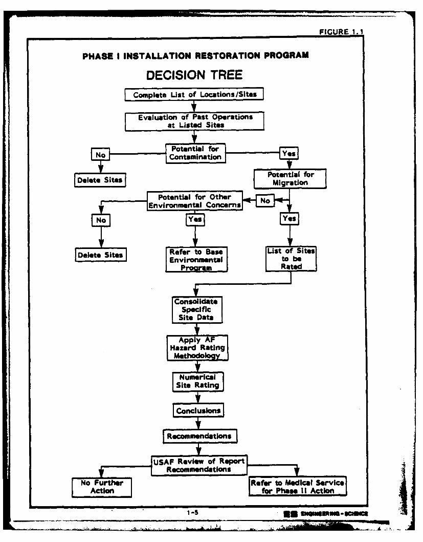
FIGURE 1. 1
PHASE I INSTALLATION RESTORATION PROGRAM
DECISION TREEComplete List of Locations/Sites
Evaluation of Past Operationsat Listed Sites
RCotmmenations
USAoenia Reieofrepr
1-5l Site uwesme-casc i
SECTION 2
INSTALLATION DESCRIPTION
LOCAT.ION, SIZE AND BOUNDARIES
O'Hare Air Reserve Forces Facility at O'Hare International Airport
is located in the Chicago metropolitan area in northeastern Illinois
(Figures 2.1 and 2.2). The airport is located northwest of downtown
Chicago at the boundary of Cook County and DuPage County. All of the
property around the airport and Air Force installation is urbanized and
used for residential, commercial and/or industrial purposes. The
military portion of O'Hare Airport is composed of approximately 400
acres of land in the northeast corner of the airport. The Air Forcealso leases a portion of the southeast taxiway. The Air Force has
retained the priority use of all runways. Figure 2.3 depicts the
configuration of the installation property.
INSTALLATION HISTORY
Initially called Orchard Place Airport, the site was activated in
October of 1942, when the government acquired a number of tracts of farm
land. The War Assets Corporation erected buildings on this land to be
used for an aircraft assembly plant.
In June of 1943, the installation was leased to Douglas Aircraft
Company as an assembly plant for the C-54 cargo aircraft. The site wasknown as the mChicago Aircraft Assembly Plant Number 8.0 During the
years of 1943 to 1945, approximately 665 aircraft were assembled and
delivered to the Army Air Corps. The plant was then closed in the fall
of 1945.
In 1946, the site was reactivated as a military installation when
the 803rd Army Air Force Reserve Specialized Depot assumed control of
the site. During this time, the 141st Air Force installation unit for
reserve training was activated at the renamed Douglas-Orchard Airport.
In 1948, the 141st was replaced by the 2471st AF Reserve Combat
Training Center. In 1949, both the 437th and the 441st Troop Carrier
2-1
-- = .... -- - .
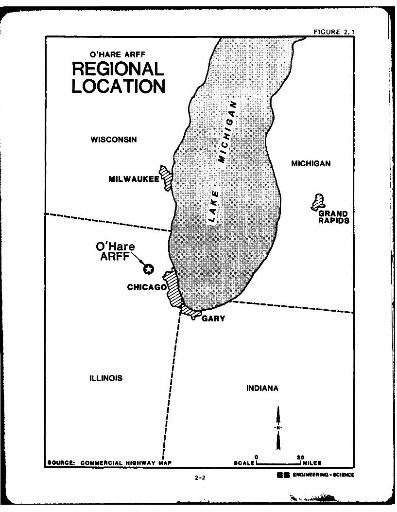
FIGURE 2.1
O'HARE ARFF
REGIONALLOCATION
WISCONSIN
........MICHIGAN
MILWAUKEE
S4GRAND
. RAPIDS
O'HareARFF\, "
CHICAGO
GARY
ILLINOIININ
I0ISOUCE:COMERCIL HGHWY MA SCLE ILE
2-
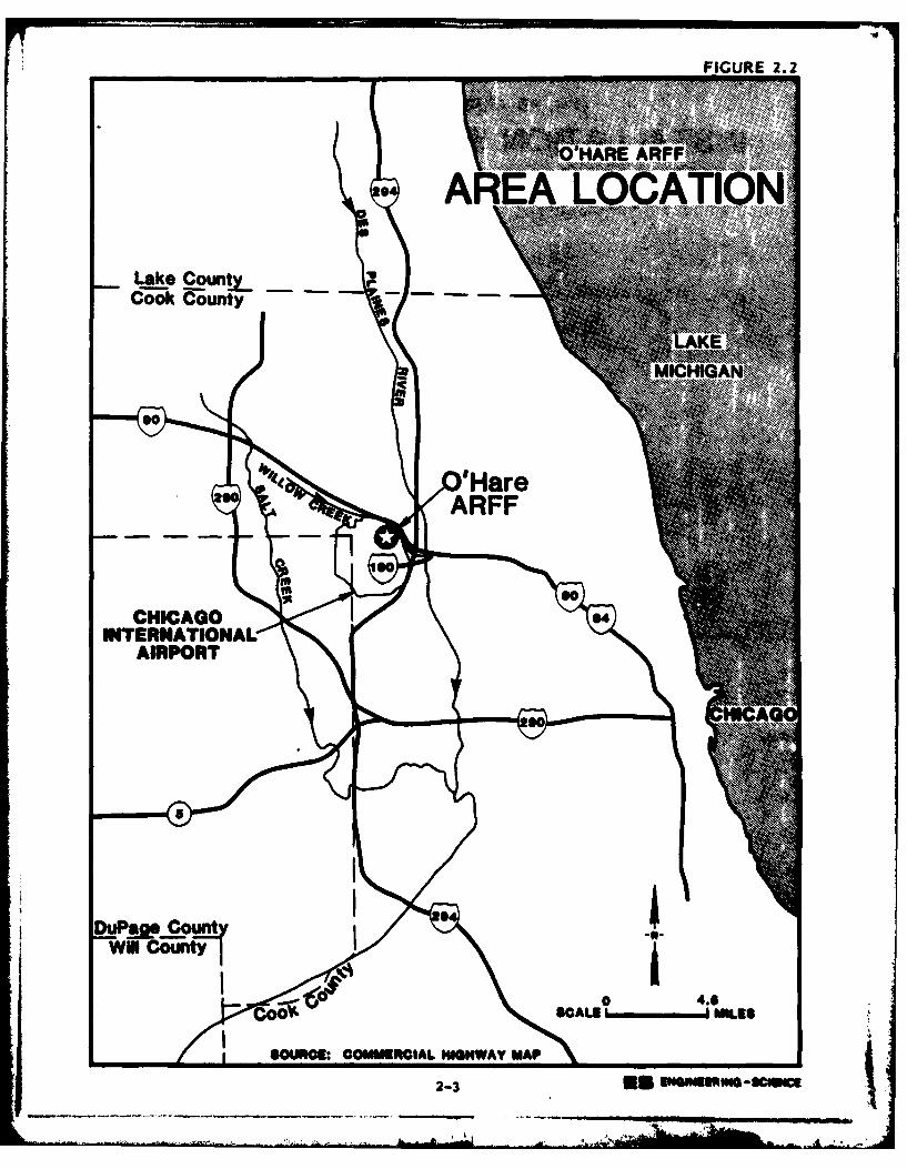
FIGURE 2.2
0 N HARE ARF.......
*AREA LOAIN
Lake CounL_Cook County
CHICAGON'
IN90AIOA
AIRPaRT
DuP~t.ARFF
SORC: OMUOILIHW90A
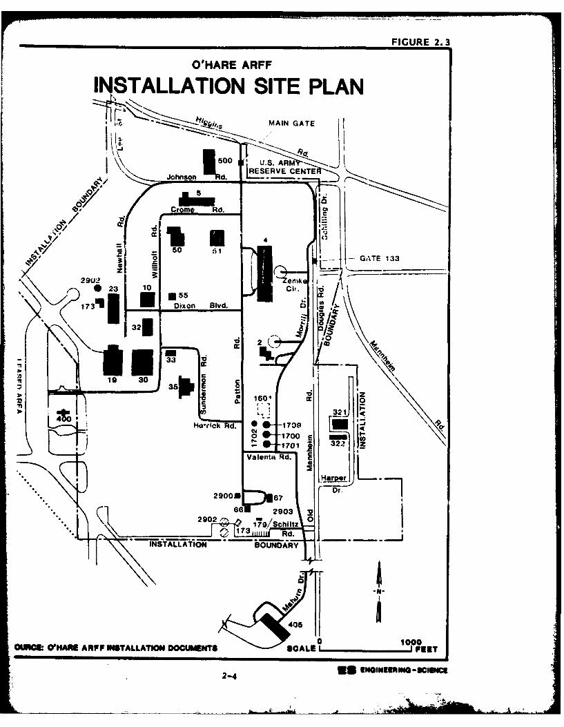
FIGURE 2.3
OHARE ARFF
INSTALLATION SITE PLANh's MAIN GATE
00 ARM~
Johnson kd0 ESR C
.5 d
.50GATE133L
2 0 - 5 Ct
17311 Dixon Blvd. C 2 13
32fl5
I, -
19 30
to 160',
*11 out 321Ho -c d. 0 1709 0
1701 - 3Valenta Rd. 2
Harper L 7* 2900KDr.
291000
OURC. UNRE RFF NSTLLATON DCUMNTS CAL I29FEE
290 7*/ UNINURNSUCf0
Wings Reserve were activated. In 1949, the military portion was re-
designated USAF O'Hare Field, Chicago International Airport.
From October 1950 until December 1957, the 2471st AFRCTC remained
the supervisory unit. In 1955, the airfields were opened to commercial
traffic.
From May 1957 until October 1970, the 928th Tactical Airlift Group
was equipped with the Fairchild C-119 wFlying Boxcar*, and in 1970 the
Lockheed C-130A "Hercules" arrived. The 928th TAG is still the in-
stallation's host unit.
ORGANIZATION AND MISSION
O'Hare ARFF at O'Hare International Airport has a fulltime staff of
1,544 employees. For one weekend per month and two full weeks per year,
the installation serves as a training facility for approximately 2400
Air Force Reservists and Air National Guardsmen.
The host organization at O'Hare ARFF is the 928th Tactical Airlift
Group (TAG). The primary mission of the 928th TAG is to provide
individual and unit training in the C-130A, tactical airlift support for
airborne forces, equipment, supplies and aeromedical evacuation within a
theater of operations. Additionally, the Group operates and maintains
the Air Force complex at O'Hare, represents the Air Force in the Chicago
metropolitan area, and provides logistical support to various on/off
installation tenants.
The on-installation tenants at the O'Hare ARFF are listed below.
Descriptions of the major tenant and other installation organizations
and their missions are presented in Appendix C.
o Defense Contract Administration Services Region
o Defense Logistics Agency
o Headquarters, Illinois Air National Guard (Ill ANG)
o 126th Air Refueling Wing, Ill AUG
o 126th Combat Support Group, Ill ANG
o 108th Air Refueling Squadron, Ill ANG
o 126th Consolidated Aircraft Maintenance Squadron, Ill ANG
o 126th USAF Clinic, Ill AUG
o 126th Civil Engineering Flight, Ill AUG
2-5
(A• . -,, ,L' • .. . -
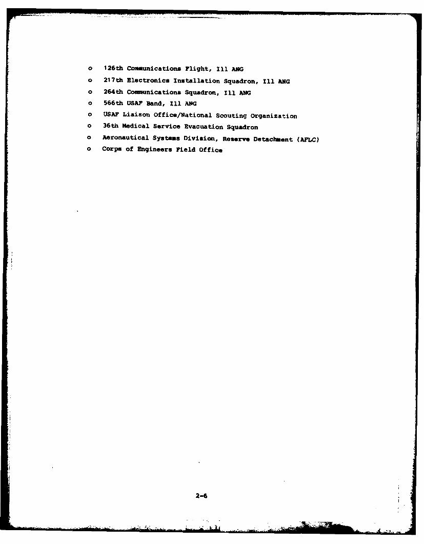
o 126th Communications Flight, Ill AUG
o 217th Electronics Installation squadron, Ill AUG
o 264th Comunications; Squadron, Ill ANG
o 566th USAF Band, Ill PG
o USAF Liaison Office/National Scouting Organization
o 36th Medical Service Evacuation Squadron
o Aeronautical Systems Division, Reserve Detachment (AFLC)
o Corps of Engineers Field Office
2-6
SECTION 3
ENVIRONMENTAL SETTING
The environmental setting of O'Hare Air Reserve Forces Facility
(ARFF) is described in this section with an emphasis on the identifi-
cation of natural features that may promote the movement of hazardous
waste contaminants. Environmental conditions pertinent to this study
are summarized at the conclusion of this section.
METEOROLOGY
Two climatic features of interest in determining the potential for
movement of contaminants are net precipitation and rainfall intensity.
Net precipitation is an indicator for the potential of leachate genera-
tion and is equal to the difference between annual precipitation and
annual evaporation. Rainfall intensity is an indicator for the poten-
tial of excessive runoff and erosion. The one-year, 24-hour rainfall
evient is used to gauge the potential for runoff and erosion.
Net precipitation at Chicago O'Hare ARFF is 4.2 inches as deter-
mined from meteorological records. Normal annual precipitation at
O'Hare International Airport for the period 1958 to 1981 is 34.17 inches
(National Oceanic and Atmospheric Administration (NOAA), 1981) and
annual evaporation for the area is 30 inches (NOAA, 1977). This value
of net precipitation indicates that there is some potential for leachate
generation at hazardous waste sites on the installation as a result of
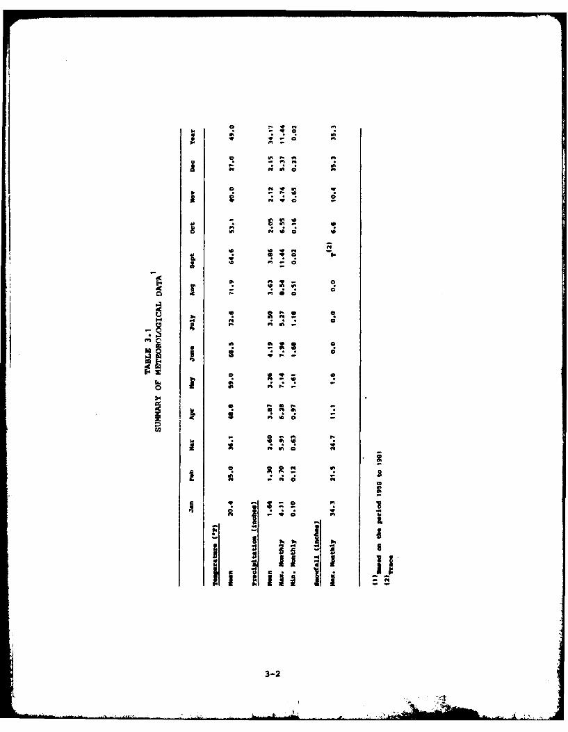
rainfall. Selected meteorological data are summarized in Table 3.1.
The one-year, 24-hour rainfall event for the installation is 2.4
inches (NOAA, 1968). This value indicates that there is a moderate
potential for erosion and transport of surface contamination from
hazardous waste sites on the installation.
3-1
F. fm I
ft ina-
In WA44t
in C! biA
in m~ 0
- IAIA C!
in on. f t
POO.9
Id. * I
a ft-a
3-2t.9 -
GEOGRAPHY
The installation is located northwest of Chicago, Illinois in the
Glaciated Central Region ground-water basin. The landscape of the region
ranges from a low, flat plain east of the installation to a poorly
drained hilly belt west of the installation. The area around the in-
stallation is highly urbanized.
The installation is in the Des Plaines River drainage basin which
is the major drainage basin in the area. The Des Plaines River
originates near the Illinois-Wisconsin border approximately 30 miles
north of the installation. The river empties into the Illinois River
approximately 50 miles south of the installation. The river flows
generally south in the vicinity of the installation (Figure 3.1).
Topography and Drainage
The topography at O'Hare ARFF slopes very gently to the northeast.
The highest point on the installation is about 650 feet mean sea level
(MSL). This point occurs along the western border of the installation
near runway 22R. The lowest point is approximately 635 feet MSL and
occurs along a drainage ditch near the installation's northern boundary.
Open drainage ditches traverse the northwest and north ends of the
installation (Figure 3.2). One drainage ditch flows east near the
northern boundary of the installation. This drainage ditch enters the
installation near the end of runway 22R. The drainage ditch exits the
installation under Higgins Road near the installation main gate and
flows into Willow Creek. A second drainage ditch flows north along the
northwest boundary of the installation and discharges into the eastward
flowing drainage ditch. Overland runoff from the northwest corner of
the installation discharges to these drainage ditches. Storm drainage
from the northern end of O'Hare International Airport drains into the
eastward flowing drainage ditch which traverses the northwest corner of
the installation.
Storm drainage from the installation discharges to Willow Creek, a
tributary of the Des Plaines River. Storm drains on the installation
direct storm runoff to an open ditch that begins at Mannheim Road east
of the installation. The open ditch drains east about 1,300 feet to
Willow Creek. The relationship between Willow Creek and installation
drainage structures is shown on Figure 3.2.
3-3
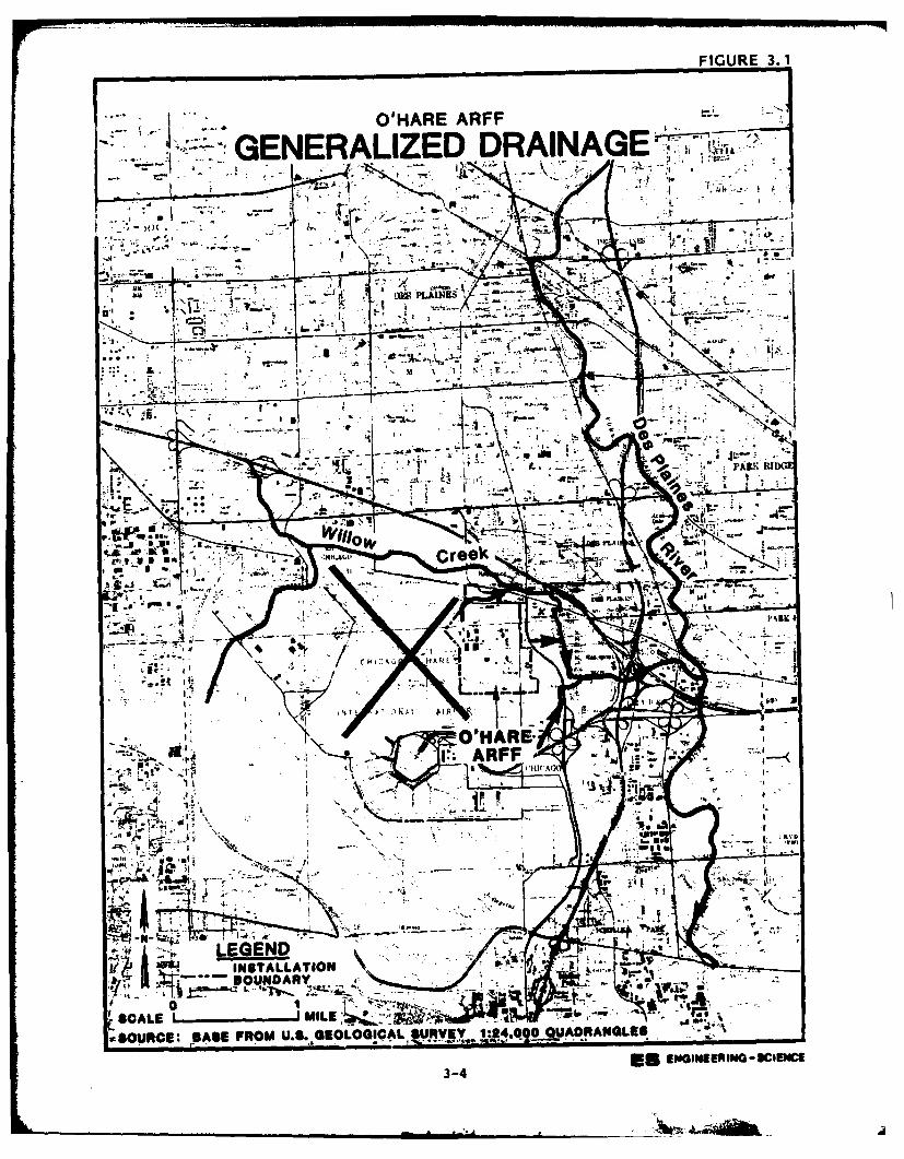
FIGURE 3. 1
O'HARE ARFF
'~ GENERALIZED DRAINAGE
li ti~~-
~~~a INTLLTO
SCAL 'IL L
4 ~~
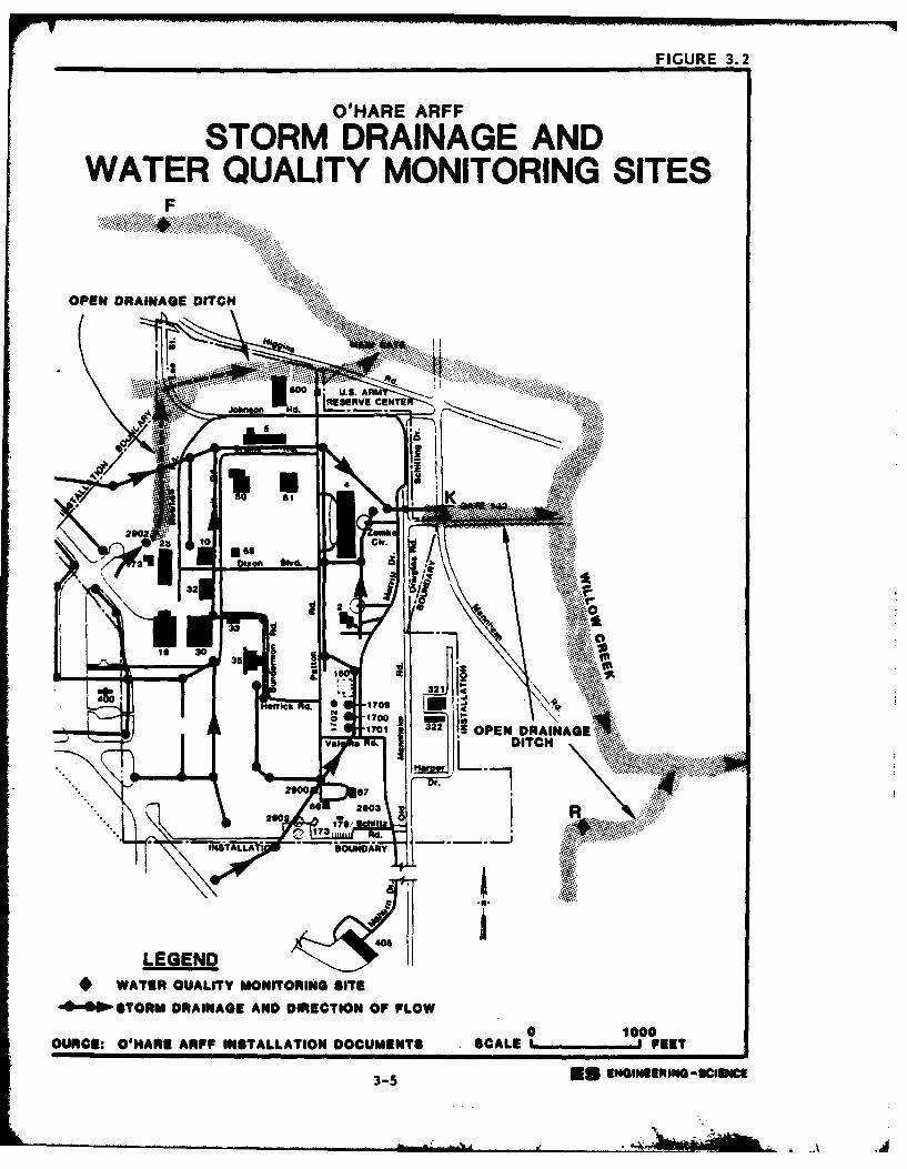
FIGURE 3.2
O'HARE ARFF
STORM DRAINAGE ANDWATER QUALITY MONITORING SITES
F
OPEN DRAINAGE DITCH -
JohlaEERVE CENTS
.................................................. .. ....
3OPE DITCHn
340
0 1000
5 *OPE DRIAENNERNGSIC
GEOLOGY
S tratigraphy
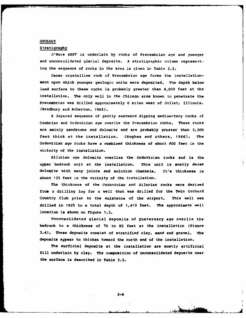
O'Hare ARFF is underlain by rocks of Precambrian acye and younger
and unconsolidated glacial depcsits. A stratigraphic column represent-
ing the sequence of rocks in the area is given in Table 3.2.
Dense crystalline rock of Precambrian age forms the installation-
ment upon which younger geologic units were deposited. The depth below
land surface to these rocks is probably greater than 4,000 feet at the
installation. The only well in the Chicago area known to penetrate the
Precambrian was drilled approximately 6 riles west of Joliet, Illinois.
(Bradbury and Atherton, 1965).
A layered sequence of gently eastward dipping sedimentary rocks of
Cambrian and Ordovician age overlie the Precambrian rocks. These rocks
are mainly sandstone and dolomite and are probably greater than 3,000
feet thick at the installation. (Hughes and others, 1966). The
Ordovician age rocks have a combined thickness of about 800 feet in the
vicinity of the installation.
Silurian age dolomite overlies the Ordovician rocks and is the
upper bedrock unit at the installation. This unit is mostly dense
dolomite with many joints and solution channels. It's thickness is
about 135 feet in the vicinity of the irstallation.
The thickness of the Ordovician and Silurian rocks were derived
from a drilling log for a well that was drilled for the Twin Orchacd
Country Club prior to the existence of the airport. This well was
drilled in 1925 to a total depth of 1,410 feet. The approximate well
location is shown on Figure 1.3.
Unconsolidated glacial deposits of Quaternary age overlie the
bedrock to a thickness of 70 to 85 feet at the installation (Figure
3.4). These deposits consist of stratified clay, sand and gravel. The
deposits appear to thicken toward the north end of the installation.
The surficial deposits at the installation are mostly artificial
fill underlain by clay. The composition of unconsolidated deposits near
the surface is described in Table 3.3.
3-6
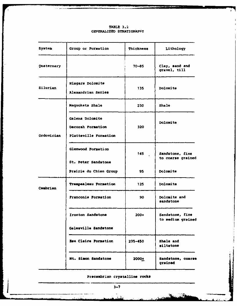
TABLE 3.2
GEVlERALIZED STRATIGRAPHY
System Group or Formation Thickness Lithology
quaternary 70-85 Clay, sand andgravel, till
Niagara DolomiteSilhurian 135 Dolomite
Alexandrian Series
Maquoketa Shale 230 Shale
Galena DolomiteDolomite
Decorah Formation 320
Ordovician Platteville Formation
Glenwood Formation145 Sandstone, fine
to coarse grainedSt. Peter Sandstone
Prairie dui Chien Group 95 Dolomite
Trempealeau Formation 125 DolomiteCambrian ___________________ ________
Franconia Formation 90 Dolomite andsandstone
Ironton Sandstone 200+ Sandstone, fineto medium grained
Galesville Sandstone
Eau Claire Formation 235-450 Shale andsiltstone
Mt. Simon Sandstone 2000± Sandstone, coarsegrained
Precambrian crystalline rocks
3-7
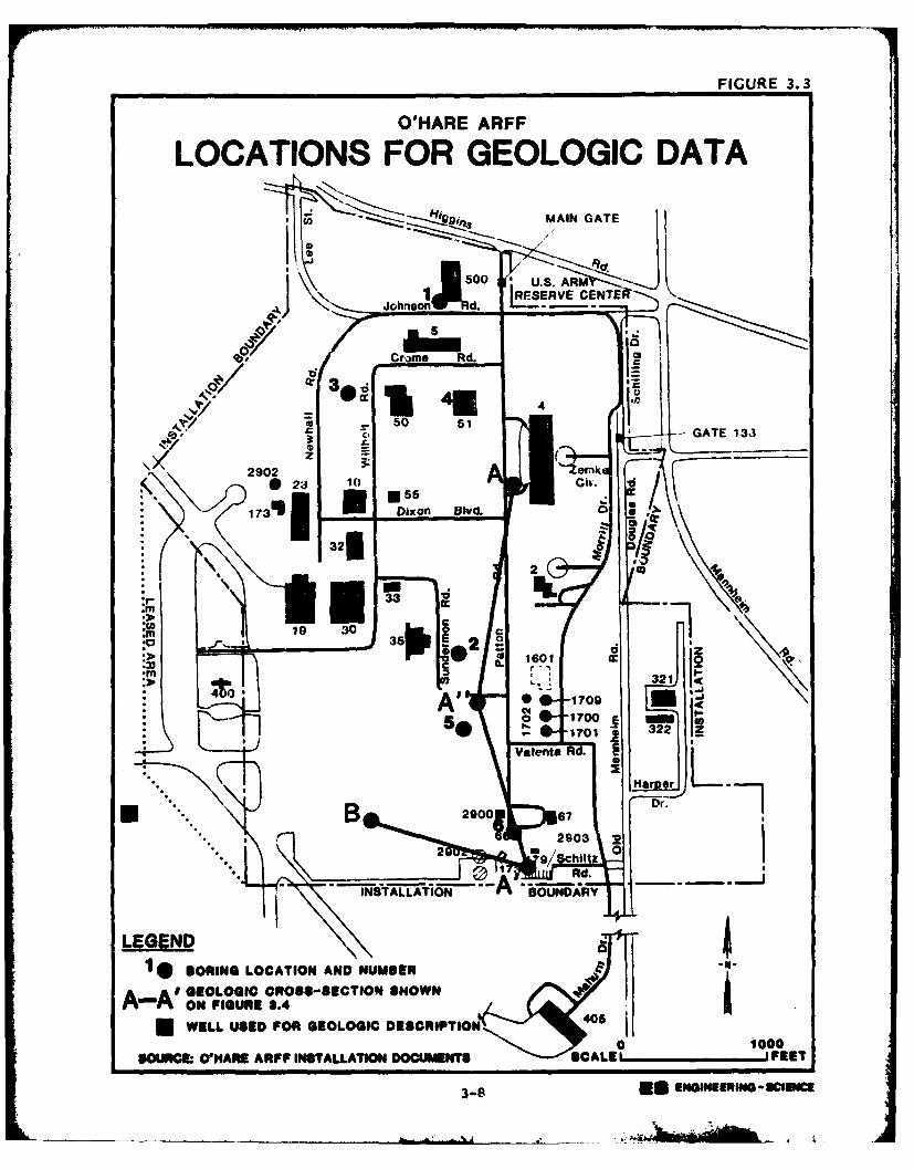
FIGURE 3.3
O'HARE ARFF
LOCATIONS FOR GEOLOGIC DATA
MAIN GATE
jL [ESERVEGENTEJohnlson~td. LES
Cr 9n Rd.
G D B=vAT 3 3
2902 A enk 7023 10 5Ci. .
.. E U .
0 o 173W Dixon Blvd.0
* 32f
19 30
c 1r 6010 PI321 4
_ A A' OnI O8-SCTONSEWa ij
*0 A
A#8 IN 709NI~m 4c
17011 322ZValera& IRd.o
B 2900 Dr.7
2 0
Rd.- - ALATI BOUNDARY- - - S
LEGEND1 S ORING LOCATION AND NUMMER 1
A-Af GELOI CROSS-SECTION SHOWN
*WELL USED FOR GEOLOGIC DESCRIPTION400 1000
SOURCM: OIIAfh ARFF INSTALLATION DOCUMENTSI SCALE' 'FEET
3-8 * ~SN~0
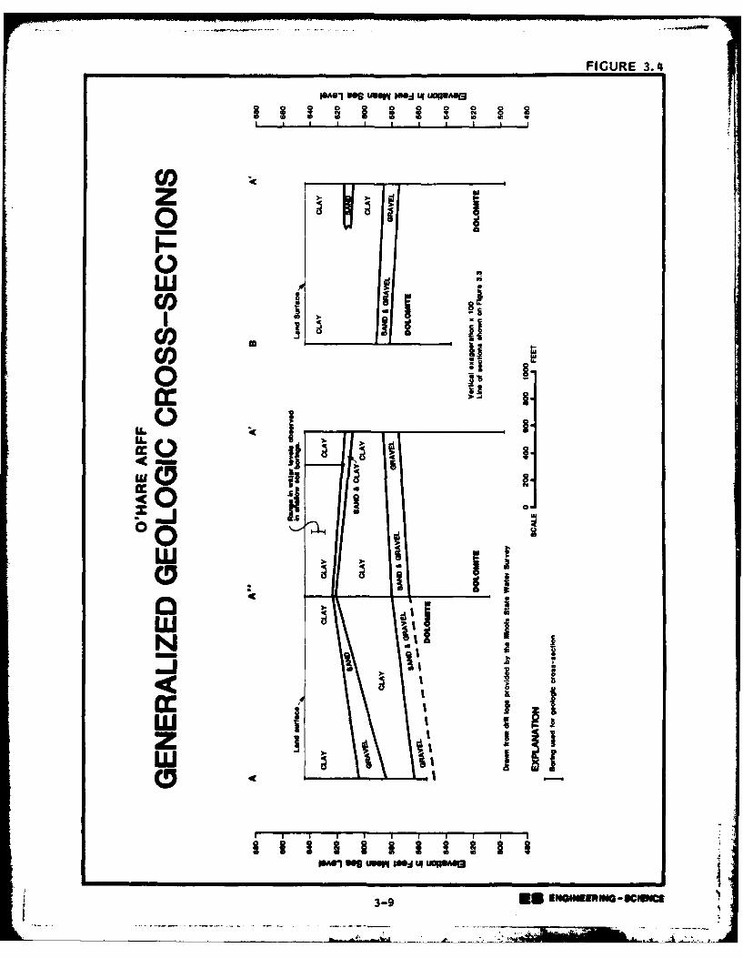
FIGURE 3.4
1"01 we Me" 1"A 4 UOBAeI i e'1 IBu I~e Iruwe
I I I I I I I I I
CO)z w
0
CO)
CO1) _3 si
CO)o
LL..
Xi j0 -Jw
)t ,t ISO
I, I I IN
i ! It i !I I ;iz-
LLI It
gSAVJ S IwM 1"14 UOPA013
3-9 IIII ENUGU-*UcE
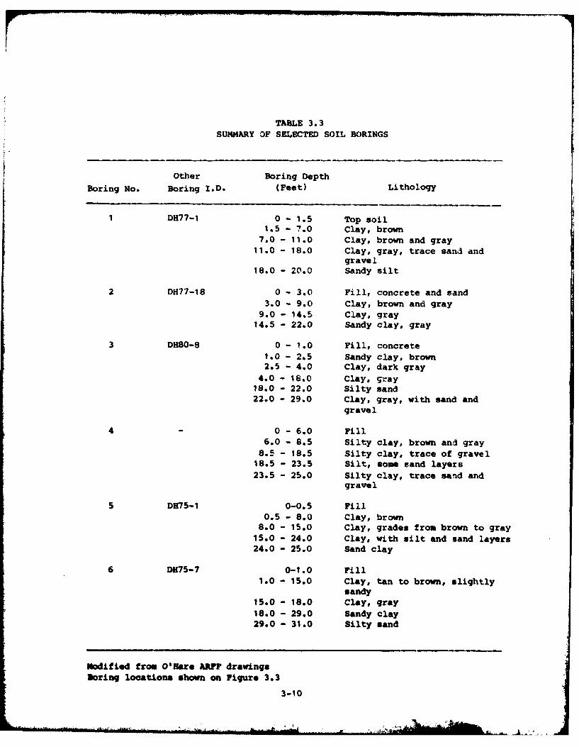
TABLE 3.3SUMMARY OF SELECTED SOIL BORINGS
Other Boring DepthBoring No. Boring I.D. (Feet) Lithology
DH77-1 0 - 1.5 Top soil1.5 - 7.0 Clay, brown
7.0 - 11.0 Clay, brown and gray11.0 - 18.0 Clay, gray, trace sand and
gravel18.0 - 20.0 Sandy silt
2 DH77-18 0 - 3.0 Fill, concrete and sand3.0 - 9.0 Clay, brown and gray
9.0 - 14.5 Clay, gray14.5 - 22.0 Sandy clay, gray
3 DHa0-B 0 - 1.0 Fill, concrete10 - 2.5 Sandy clay, brown2.5 - 4.0 Clay, dark gray
4.0 - 18.0 Clay, gray18.0 - 22.0 Silty sand22.0 - 29.0 Clay, gray, with sand and
gravel
40 - 6.0 Fill6.0 - 6.5 Silty clay, brown and gray
8.5 - 18.5 Silty clay, trace of gravel18.5 - 23.5 Silt, some sand layers23.5 - 25.0 Silty clay, trace sand and
gravel
5 DH75-1 0-0.5 Fill0.5 - 8.0 Clay, brown
8.0 - 15.0 Clay, grades from brown to gray15.0 - 24.0 Clay, with silt and sand layers24.0 - 25.0 Sand clay
6 DM75-7 0-1.0 Fill1.0 - 15.0 Clay, tan to brown, slightly
sandy15.0 - 18.0 Clay, gray18.0 - 29.0 Sandy clay29.0 - 31.0 Silty sand
Modified from O'Hare AMr? drawingsBoring locations shown on Figure 3.3
3-10
Structure
The Chicago area is located near the crest of a broad, gently
sloping arch composed mostly of Cambrian, Ordovician and Silurian rocks.
The longitudinal axis of this arch runs generally in a northwest-south-
east direction. The rocks have a general eastward dip that results from
the eastward plunge of the arch.
The major structural feature near the installation is the Des
Plaines Disturbance. Rocks in the area of the Disturbance are intensely
faulted. The origin of the faulting is unknown but has been speculated
to have been caused by a meteorite impact (Willman, 1971). The area of
the Des Plaines Disturbance is approximately five-miles square. The
southern end of the Disturbance is located approximately one-mile north
of the installation.
HYDROLOGY
Subsurface Hydrology
There are four major aquifer systems in the vicinity of O'Hare
ARFF. These aquifer systems are sand and gravel deposits of the glacial
drift, shallow dolomites composed mostly of Silurian age rocks, the Cam-
brian-Ordovician aquifer system and the Mt. Simon aquifer. The glacial
drift and shallow dolomite aquifers are separated from the underlying
deeper aquifers by the Maquoketa Shale.
The glacial drift and shallow dolomite are of greatest interest for
this study. These are the uppermost geologic units at the installation.
The glacial drift and shallow dolomite are both recharged locally
from precipitation and are hydrologically connected in the Chicago area
(Suter, 1959). The hydrologic connection is generally good whenever
sand and gravel directly overlies the dolomite. This situation exists
at O'Hare ARFF (Figure 3.4).
The glacial drift in the vicinity of the installation has an
average vertical hydraulic conductivity, or permeability, on the order
of 0.005 gallons per day per square foot (2.4 x 10- 7 centimeters per
second). This estimate assumes that recharge through the drift averages
140,000 gallons per day per square mile and that recharge is occurring
3-11
under a unit hydraulic gradient. These assumptions appear reasonable
based on work done by Walton (1965) in DuPage county that is immediately
west of the installation. This permeability estimate indicates that
percolation to the water table of the installation is low.
Ground-water elevations and ground-water flow directions in the
shallow dolomrite are not known at the installation. weter levels in
borings completed in the shallow dolomite on the installation stood at
an elevation of 625 to 630 feet mean sea level in 1942. This water
level was 15 to 20 feet below land surface. Water levels in the shallow
dolomite were generally greater than 50 feet below land surface in
DuPage County west of the installation in 1965 (walton, 1965).
The unconsolidated deposits are saturated in part at the instal-
lation (Figure 3.4). Water levels have been observed 5 to 15 feet
below land surface in shallow soil borings drilled on the installation
between 1975 and 1980 for foundation investigations.
There is a potential for contamination of ground water to occur at
subsurface waste disposal sites on the installation. The glacial de-
posits are at least periodically saturated at depths of 5 feet and more
below land surface. Waste material buried to depths of 5 feet or more
would be periodically saturated and could create leachate. Also, there
would be a tendency for the leachate to move downward to the shallow
dolomite aquifer.
Surface Hydrolo
O'Hare ARFF is in the Willow Creek drainage basin. The installa-
tion is drained by a combination of open channels and drainage struc-
tures that discharge to the creek (Figure 3.2). The main stem of Willow
Creek does not traverse the installation.
Periodic flooding can be expected at the north end of the installa-
tion. These floodwaters originate mostly as runoff from O'Hare Inter-
national Airport and from the urbanized area west and north of the
airport. The approximate limits of flooding for the 100-year flood
event are shown on Figure 3.5.
3-12
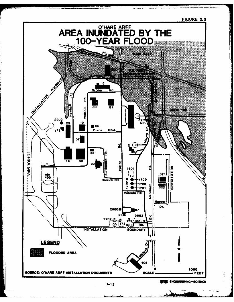
FIGURE 3.5
O'HARE ARFF
AREA INUNDATED BY THE.100-YEAR
"I W111...............
5,be c
"Ell iix
60 51
2902 3: am23 10 Cir.
055 -jDixon Blvd.
32 k*,:iiiij
2
335"
19 303
01m
3214 0
Hoff ick-17'00 E
322
Valenta Rd-.-
Maro rDr.
2900MP67
so 2903 322902 1,9 hiltz 0
7Q 173 Rd.
INSYALLAY16-N " BOUNDARY
LEGEN
FLOODED AREA
406
.0 1000SOURCM WHAM ARFF NGTALLATION DOMMANT8 WALE FEET
3-13 ENGINEERING -setemet
WATER USE
The installation receives its water supply from the City of
Chicago. Surface and ground waters are not used for installation
supply.
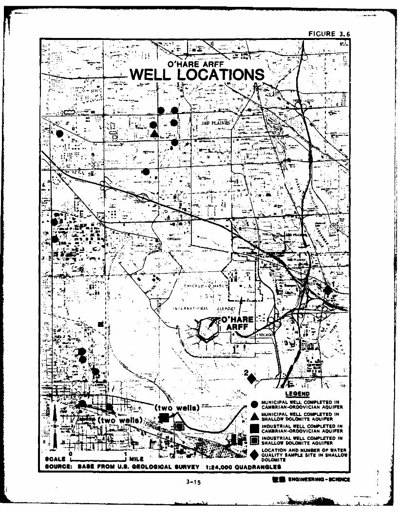
Numerous industrial and municipal supply wells are located in the
vicinity of the installation. Most wells are 1,000 to 2,000 feet deep
and withdraw water from the Cambrian-Ordovician aquifer system. A few
wells withdraw water from the shallow d~lomite aquifer system. The
approximate location of the wells that could be identifiel from the
available data are shown on Figure 3.6. (Six water supply wells are not
plotted on the figure; insufficient data were available to determine the
location of the wells within the section.)
Some residential wells exist in the vicinity of the installation
(R. T. Sasman, Illinois State Water Survey, oral communication, 1983).
The closest well completed in the shallow dolomite is located approxi-
mately one and one-half miles east of the installation.
WATER QUALITY
Surface water quality is monitored in the Willow Creek watershed by
personnel employed by the airport facility. (Landrum and Brown, 1483).
The parameters monitored include biochemical oxygen demand (BOD), pH,
suspended solids, total dissolved solids, fats, oil and grease, dis-
solved oxygen and hexane solubles. The locations of the monitoring
sites (F, K and R) in the vicinity of the installation are shown on
Figure 3.2 and the monLtoring results for the period November 1981 to
October 1982 are summarized in Table 3.4. Runoff from the installation
is monitored at site K.
The results of water quality monitoring indicates that water dis-
charging to the creek from the installation does not meet all NPDES/-
Illinois Environmental Protection Agency (IEPA) standards. (Landrum and
Brown, 1983). Suspended solids in the water generally exceeded stan-
dards and fats, oil and grease in the water have exceeded standards.
Water quality parameters in other surface waters nearby also exceed
IEPA standards (Table 3.4). Discharge standards are generally exceeded
in Willow Creek at site F above the confluence with the installation
drainage ditch and at site R in a drainage ditch that discharges to
3-14
t-A
- ~ ~ ~O'HAREf ARFF F~R .
77 WELL LOCATIONS /
IN S ..
-1.~~--- .. ...ASINO D CA AQUIFr-'~~~~~ ' ~ ~ AIN JTR LWELCML EDI
IL$ SHALO DOOIEAIE~~kL -~ -U A. LOCA T NDNm EROWA
o ULIYSMLEST N HLOSCL ML OLMT
SORC:BAERM .S EOOGCL4 SUVE L:400QUDAGE3-1 ~*5 EGINER IW - ST11C
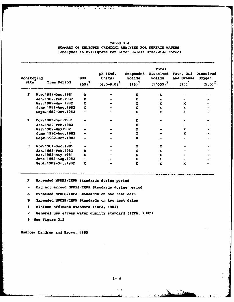
TABLE 3.4SUMMKiRY OF SELECTED CHUIICAL ANALYSES FOR SURFACE WATERS(Analyses in Milligrams Per Liter Unless O-.herwise Noted)
TotalPH (std. Suspended Dissolved Fats, Oil Dissolved
I4onito~ing BOD Units) Solids Solids and Grease Oxygen
sie Tm eid (30)1 (6.0-9.0)1 (15)1 (11000)2 (15)1 (5.0)2
F Nov.1981-Dec.1981 A - X A --
Jan.1982-Feb.1982 X - X---Mar.1982-May 1982 X - X X X-June 1981-Aug.1982 X - X X X -
Sept.1982-Oct.1982 - - X X K
K lov.1981-Dec.1981 - - X ---
Jan.1982-Feb.1982 - - x ---
Mar.1982-May1982 - - X - X
June 1982-Aug.1982 - - X - X-Sept.1982-Oct.1982 - - X - - -
R Nov. 1981 -Dec .. 1981 - - X X - -
Jan. 1982-Feb., 1962 B - X X - -
Mar. 1982-Hay 1981 K - K K - -
June 1982-Aug.1982 - - x X - -
Sept.19S2-Oct.1982 K - K X X -
X Exceeded NPDES/IEPA Standards during period
- Did not exceed NPDES/IEPA Standards during period
A Exceeded NPDES/IEPA Standards on one test date
B Exceeded NPDES/IZP& Standards on two test dates
1 Minimum effluent standard (IZPA, 1982)
2 General use stream water quality standard (IEPA, 1982)
3 See Figure 3.2
Source: Landrum and Brown, 1983
3-16
Willow Creek downstream from the installation drainage ditch. Poor
water quality is typical of highly urbanized areas.
Water quality data for the shallow dolomite aquifer (Table 3.5) are
available at two locations near the installation (Figure 3.6). One
location is a
residential supply well located approximately 1.5 miles east of the in-
stallation. The other location is a test well located approximately 1.5
miles south of the installation.
Water from the shallow dolomite is high in dissolved minerals
(Table 3.5). The total dissolved solids content in the water is above
recommended limits for public water supplies (USEPA, 1975). The iron
content of the water is near the recommended upper limit.
The shallow dolomite well east of the installation (Figure 3.6,Well No. 1) shows signs of contamination. The chloride and sulfate
contents in the water appear high and surfactants were detected in the
water. Surfactants do not occur naturally in water. The contamination
could result from any number of sources.
BIOTIC DWVIRONGINT
O'Hare ARFF has limited habitat available for wildlife. The in-
stallation consists mainly of cultivated lawns, building sites, and
paved areas which offer negligible shelter for animals. Small tracts of
unmowed brush and grass provide forage and cover for small mamals and
birds. There are no threatened or endangered plant or animal species
inhabiting the installation property. Four endangered animal species
are known to inhabit the region (within 50 miles) and may occasionally
visit the installation or airport. These are the Indiana bat, peregrine
falcon, upland sandpiper, and marsh hawk. There is no indication that
past installation activities have disrupted the patterns of these
species.
SUMARY Or DWIRON3ML SZTTING
The enviromental setting data reviewed for this investigation
identified the following major points that are relevant to O'Hare ARM.
o Net precipitation at the installation is 4.2 inches which in-
dicates that there is some potential for leachate generation at
3-17
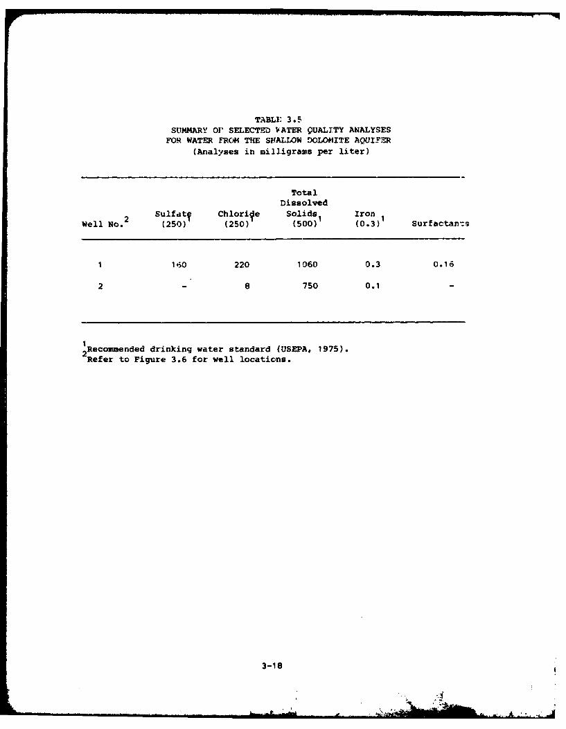
TABLE 3.5SUMMARY 0' SELECTED VATER QUALITY ANALYSES
FOR WATER FROM THE SHALLOW DOLOMITE AQUIFER(Analyses in milligrams per liter)
TotalDissolved
2 Sulfdtv Chlorife Solids Iron 1Well No. (250) (250) (500)1 (0.3) Surfactan's
1 160 220 1060 0.3 0.16
2 - 8 750 0.1 -
1Recommended drinking water standard (USEPA, 1975).2Refer to Figure 3.6 for well locations.
3-18
hazardous waste sites and movement of contaminants in ground
water. Rainfall intensity at the installation indicates that
there is only a slight potential for erosion and transport of
surface contamination from hazardous waste sites. The one-year,
24 hour rainfall event used to gauge erosion and runoff po-
tential was 2.4 inches.
o The permeability of the surficial unconsolidated deposits at the
installation is on the order of 10- 7 cm/sec which does not allow
for rapid infiltration of water.
o Four aquifer systems exist at the installation. These aquifer
systems are in descending order, the glacial drift aquifer, the
shallow dolomite aquifer, the Cambrian-Ordovician aquifer system
and the Mt. Simon aquifer.
o The upper glacial drift and shallow dolomite aquifers at the
installation are hydraulically connected and are separated fromthe underlying Cambrian-Ordovician and Mt. Simon aquifers by the
relatively impermeable Makoqueta Shale.
o Numerous wells are located in the vincinity of the installation.
Industrial and municipal wells near the installation generally
withdraw water from the Cambrian-Ordovician aquifer system. The
one residential well and one test well identified from the
available data withdraw water from the shallow dolomite aquifer.
This water is high in dissolved solids and iron.
o Contamination of ground water may potentially occur at subsur-
face waste disposal sites on the installation. The glacial de-
posits are at least periodically saturated at depths as shallow
as 5 feet below land surface.
o Surface runoff from the installation generally does not meet
IEPA stream water quality standards, but is comparable to thewater quality upstream in Willow Creek. This poor water quality
is typical of highly urbanized areas.
o Portions of the north end of the installation are within the
100-year flood plan.
o No threatened or endangered plant or animal species inhabit the
installation property.
3-19
SECTION 4
FINDINGS
To assess hazardous waste management at O'Hare Air Reserve Forces
Facility (ARFF) at O'Hare International Airport, past activities of
waste generation and disposal methods were reviewed. This section
summarizes the hazardous waste generated by activity; describes waste
disposal methods; identifies the disposal sites located on the base; and
evaluates the potential for environmental contamination.
PAST SHOP AND INSTALLATION ACTIVITY REVIEW
A review was conducted of current and past Air Force activities at
O'Hare ARFF with the objective of identifying those installation acti-
vities that generated hazardous waste. This review consisted of a
search of files and records, interviews with installation employees, and
site inspection.
The sources of hazardous wastes at O'Hare ARFF can be associated
with any one of the activities listed below:
o Industrial Shops
o Fire Protection Training
o Pesticide Utilization
o Waste Storage Areas
o Fuels Management
The following discussion addresses only those wastes generated on
the installation which are either hazardous or potentially hazardous.
Hazardous wastes are those wastes referenced by the Comprehensive
Environmental Response, Compensation, and Liability Act of 1980 (CURCLA,
Public Law 96-510). A potentially hazardous waste is one which is
suspected of being hazardous although insufficient data are available to
fully characterize the waste material.
4-1
I 1
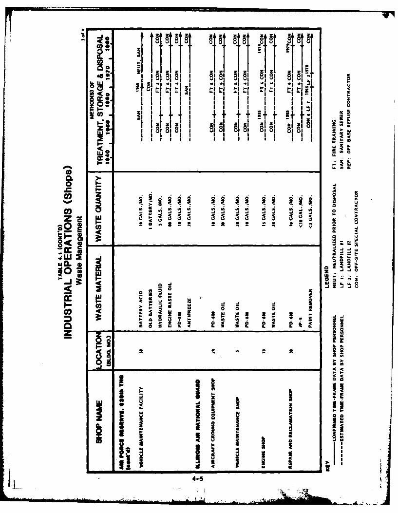
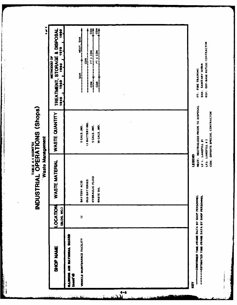
INDUSTRIAL OPERATIONS (SHOPS)
Since the O'Hare ARFF opened in 1946, the main function of the
industrial operations (shops) on the installation has been to provide
maintenance support activities to aircraft flying missions. Activit:.es
have included aircraft equipment maintenar.ce, ground equirvent main-
tenance, and installation facilities maintenance. A list of present
industrial shops was obtained from the installation clinic files,
Information contained in the files indicates if the shops handle
hazardous materials and generate hazardous waste. A summary of the
pertinent information from the shop files is presented in Appendix E,
Master List of Industrial Shops.
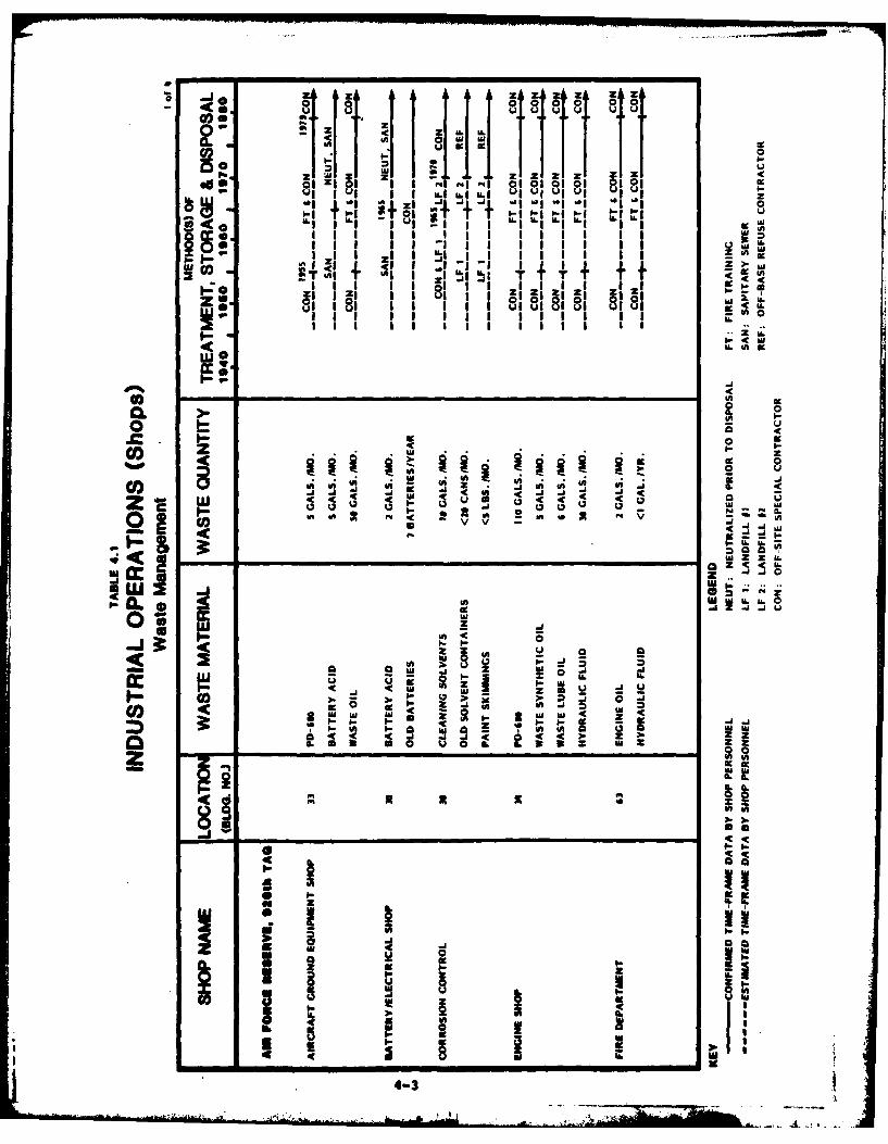
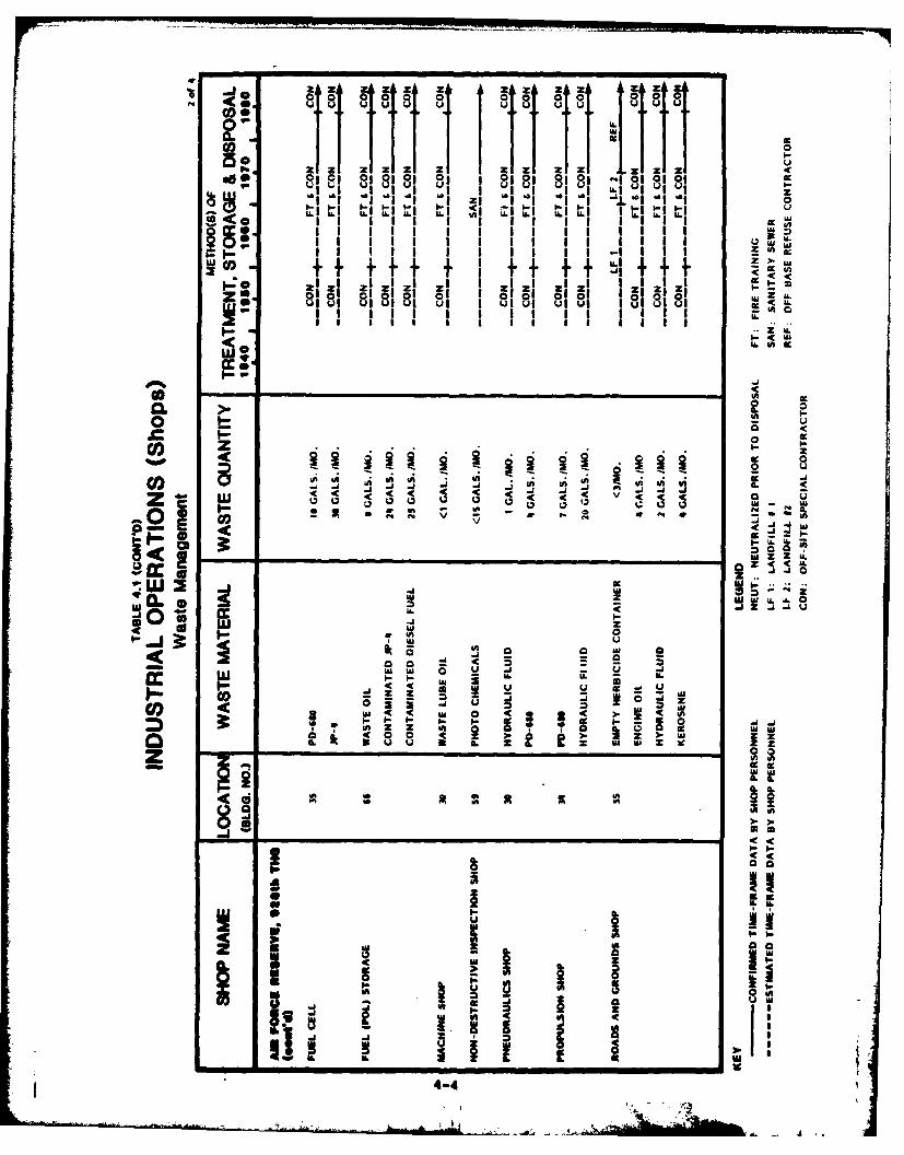
For the shops known to generate hazardous wastes, interviews with
personnel familiar with shop activities were conducted. The information
obtained from interviews and installation records has been summarized in
Table 4.1. For each generator of hazardous wastes, this table presents
the shop location, waste materials generated, quantities of wastes gene-
rated, and a disposal method timeline. Many of the disposal methods
were identified from information obtained from past and present person-
nel of O'Hare ARFF. The waste quantities shown in Table 4.1 are based
on verbal estimates given by present shop personnel at the time of the
interviews. The shops that have generated insignificant quantities or
no hazarious waste are not listed in Table 4.1.
From 1943 to 1945 the area that is now O'Hare ARFF was a govern-
ment-owned, contractor-operated plant (Douglas Aircraft Assembly Plant
No. 8). Assembly operations typically do not generate significant
amounts of hazardous solid waste. Most of the hazardous waste generated
resulted from the painting operations. Several underground tanks stored
paint thinners and fuels. All but one of these tanks (a fuel tank) have
since been excavated and removed. Paper and other office materials were
burned in an incinerator. Other wastes generated by this operation were
disposed of in a manner that is not well defined. There are no records
of any landfilling or other disposal operations during this period of
time.
In the early years of installation operations, (1946 to 1955), an
off-sits contractor collected combustible liquid wastes (primarily mote
oil) and removed them from the installation. From approximately 1955 to
4-2
-- x I , Z& k z z i Z , z , z z
.. L.U
i t I i ti
1 I 0I I II I 0 8" -.
- I I I .- I- "1 -' l I I I'l , ° I I Ioo <1 I de I Il I I iiii II
I I I I I I Ii I II
E--"
0 .-
Mo
U. IA d.c
W- 0
w#k ow z
0 o v P I3C Sz -C < w
e. ( i .2'
w 24-1
#A .. : =! ..aB CI) j ,.. -a 0
666
z IIv ,- I I-
ZI in I w.Z<l < ). I'
30-
z , I Z, ZNX Z a
Suuu u u 8 S- 1
II I Iii lLL I. I6 L I I. u I I -I .I I. I. I I 6
-A
I -
60 U. W
.~IAIA * U~ A IA
CoI.,*>( -
w. j -A 0j j -
1W U
.0I
tm~~ Z LL u g -
LU 2A j j
ILI z
-jL
w us 0I- a I.U< ou L
- 9 )' zgL L Z IL4-4
ai A i A z z A A z Z Z zoI o 000 00 0 00 0 0
"I U U U U Ul U) goU
as g 1 U UU gld'' UU~
111111 )-I )I . I IIOf i I IIL I I Q . 6 61L1 LL
I III
11 11 I I II aa ~ ~I 1 1 I c I I olI Iu ozI Z uel UWWK
It IIi5
111111I II I L i
II.
0.
co9J -1Z ~ ' 4 C -4 44 4z
0
0 'U W
0. a ll.J~~~~~ Z4Ca4iuswwU.
.J .J -I--c I ' w
at
< 4
II.m
31 Ii )wI
4-
I 1l010
ULUI z
* I r -
P: 0 A 1 1Ifati&6(i tu
0
0 cc
-
a 0U3
U)MI
atp~iA
~ _ _ _ _ _ _ _ _ _ _ _ _ _ _ __4_ _
1979, combustible wastes were burned at the Fire Protection Training
Areas (see following discussion). Presently these wastes are drummed
and stored for outside contract disposal.
Cleaning solvents and related wastes were sometimes removed by the
off-site contractor in the early years. At other times, the solvent-
type wastes were drummed and disposed of in one of the two installation
landfills.
Solids waste generated by shop operations, along with the rest of
the installation's general rubbish, was disposed of in the installation
landfills through 1970, when landfilling operations ceased. Since then
it has been removed from the installation by a contract-disposal com-
pany.
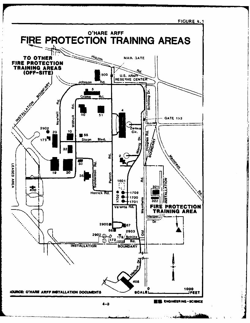
Fire Protection Training
Since 1955, fire protection training exercises have been conducted
by the Air Force at three locations. Only one of these was located on
what is now installation property (Figure 4.1). Prior to 1955, it is
uncertain what, if any, fire protection training was done.
Fire Protection Training Area
From approximately 1955 to the early 1960's, the Air Force fire
department conducted fire training exercises in an area on the southeast
side of the installation. The burn pit was constructed with an earth
berm and a natural soil bottom. AVGAS, MOGAS, waste oil and combustible
liquids were burned here. It is unknown whether there was any water
presoaking, or how frequently training was practiced or what extinguish-
ing agents were used. No visual evidence of the site was present during
the site visit since the area is now covered by a hardfill area.
Other Fire Protection Training Areas
From the early 1960's through the present day, fire training exer-
cises have taken place at two sites on O'Hare International Airport
property under a joint training agreement. One Fire Protection Training
Facility was located just north of Old Higgins Road. The current Fire
Protection Training Facility is located approximately one mile south of
the second site.
Pesticide Utilization
Pesticide applications have been conducted by the Roads and Grounds
Shop and O'Hare ARFF throughout the history of the installation. Cur-
rently, shop personnel apply 2-Prometon (an amine herbicide) annually
4-7
. . . .. ... - -- II . A. . ,
FIUR 4.O'HARE ARFF
FIRE PROTECTION TRAINING AREAS
TO OTHER M A.1 -3AT EFIRE PROTECTION/TRAINING AREAS
(OFF-SITE)150 usiJJohnwn d. ~ USVE CENTE
Johnsoin ___Rd.0 LS
.55
4b, Crm d
z 21 5321
Heric 23 110 Ci
'55,17310 Dixn Bvd3270 ~ 3
:01AOI~~~0U.~' 2'~f AfF TLLTO OUMT F
4-8 rM3 -dINE INuSI
throughout the installation for general weed control. All of the pesti-
cide material prepared is used up in the application process. No other
pesticides or herbicides were reported as being used. Containers are
rinsed and dispo3ed of as general refuse.
Waste Storage Areas
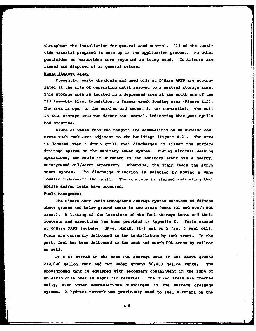
Presently, waste chemicals and used oils at O'Hare ARFF are accumu-
lated at the site of generation until removed to a central storage area.
This storage area is located in a depressed area at the south end of the
Old Assembly Plant foundation, a former truck loading area (Figure 4.2).
The area is open to the weather and access is not controlled. The soil
in this storage area was darker than normal, indicating that past spills
had occurred.
Drums of waste from the hangers are accumulated on an outside con-
crete wash rack area adjacent to the buildings (Figure 4.2). The area
is located over a drain grill that discharges to either the surface
drainage system or the sanitary sewer system. During aircraft washing
operations, the drain is directed to the sanitary sewer via a nearby,
underground oil/water separator. Otherwise, the drain feeds the storm
sewer system. The discharge direction is selected by moving a vane
located underneath the grill. The concrete is stained indicating that
spills and/or leaks have occurred.
Fuels Management
The O'Hare ARFF Fuels Management storage system consists of fifteen
above ground and below ground tanks in two areas (west POL and south POL
areas). A listing of the locations of the fuel storage tanks and their
contents and capacities has been provided in Appendix D. Fuels stored
at O'Hare ARFF include: JP-4, MOGAS, FS-5 and FS-2 (No. 2 Fuel Oil).
Fuels are currently delivered to the installation by tank truck. In the
past, fuel has been delivered to the west and south POL areas by railcar
as well.
JP-4 is stored in the west POL storage area in one above ground
210,000 gallon tank and two under ground 50,000 gallon tanks. The
aboveground tank is equipped with secondary containment in the form of
an earth dike over an asphaltic material. The diked areas are checked
daily, with water accumulations discharged to the surface drainage
system. A hydrant network was previously used to fuel aircraft on the
4-9
O'HARE ARFFGUREF.
HAZARDOUS WASTE DRUMACCUMULATION AND STORAGE SITES
MAIN GATE
U.S. A M-
5: L ESERVE CENIE
Crome d.
tB-
2902 ! '. GATE 133
731Dixon Blvd.0
32E. DRUM
3F CCUMULATI N 1j7ASSEMLY161 Ix3
1-i1K TRAE 6 20O
SOUNCE.~~ ~Heric Rd.AR A0-INTLL-O1DC7ET 05
SOUT END OF t-IEEISSCU
west aircraft apron. This network was shut down in the early 1970's for
replacement. Currently fuel leaves the area through the new hydrant
system and in tank trucks. The South POL area has nine 25,000 gallon
and two 11,500 gallon above ground JP-4 tanks. It also has has one
25,000 gallon above ground tank which has been partitioned in two, with
one half holding 12,500 gallons of FS-2 and the other half nearly empty.
At one time, this other half held engine oil. Fuel is removed from this
area for use by tank truck only.
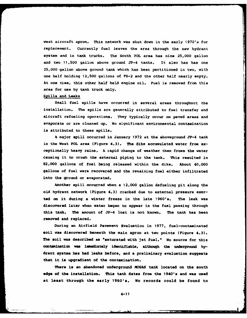
Spills and Leaks
Small fuel spills have occurred in several areas throughout the
installation. The spills are generally attributed to fuel transfer and
aircraft refueling operations. They typically occur on paved areas and
evaporate or are cleaned up. No significant environmental contamination
is attributed to these spills.
A major spill occurred in January 1972 at the aboveground JP-4 tank
in the West POL area (Figure 4.3). The dike accumulated water from ex-
ceptionally heavy rains. A rapid change of weather then froze the water
causing it to crush the external piping to the tank. This resulted in
82,000 gallons of fuel being released within the dike. About 40,000
gallons of fuel were recovered and the remaining fuel either infiltrated
into the ground or evaporated.
Another spill occurred when a 12,000 gallon defueling pit along the
old hydrant network (Figure 4.3) cracked due to external pressure exer-
ted on it during a winter freeze in the late 1960's. The leak was
discovered later when water began to appear in the fuel passing through
this tank. The amount of JP-4 lost is not known. The tank has been
removed and replaced.
During an Airfield Pavement Evaluation in 1977, fuel-contaminated
soil was discovered beneath the main apron at two points (Figure 4.3).
The soil was described as *saturated with jet fuel." No source for this
contamination was immediately identifiable, although the underground hy-
drant system has had leaks before, and a preliminary evaluation suggests
that it is upgradient of the contamination.
There is an abandoned underground 4OGAS tank located on the south
edge of the installation. This tank dates from the 1940's and was used
at least through the early 1960's. No records could be found to
4-11
• ___________
FIGURE 4.3
O'HARE ARFF
POL SPILLS AND LEAKS9 1) MAIN Gt TE
rnzo US RMLE!RECENTEii
JP-4 BULK 4TANK SPILL~ 50 51E 3
290 emke* 231 10 Cur.1 )7311 DixUon Blvd.
-rHYDRANT 32
* SYSTEMI
DEFUELIAN -
19 1601 0
32 Il1.r~ick 0 1709
FUETELIO 0 1700 E 32c- 1701 32
CONTAMINATED Valenita Rd.
POINTS Hrp
29000000
SOUCE OHREARF ISTAAINCMENTSI BOUNDET
4-12 -* NSRN-CEc
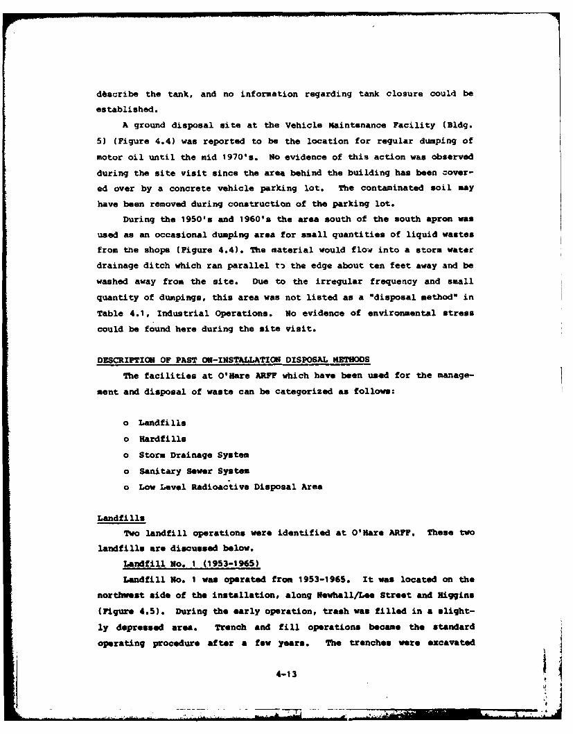
d6scribe the tank, and no information regarding tank closure could be
established.
A ground disposal site at the Vehicle Maintenance Facility (Bldg.
5) (Figure 4.4) was reported to be the location for regular dumping of
motor oil until the mid 1970's. No evidence of this action was observed
during the site visit since the area behind the building has been cover-
ed over by a concrete vehicle parking lot. The contaminated soil may
have been removed during construction of the parking lot.
During the 1950's and 1960's the area south of the south apron was
used as an occasional dumping area for small quantities of liquid wastes
from the shops (Figure 4.4). The material would flow into a storm water
drainage ditch which ran parallel t3 the edge about ten feet away and be
washed away from the site. Due to the irregular frequency and small
quantity of dumpings, this area was not listed as a "disposal method" in
Table 4.1, Industrial Operations. No evidence of environmental stress
could be found here during the site visit.
DESCRIPTION OF PAST ON-INSTALLATION DISPOSAL METhODS
The facilities at O'Hare ARFF which have been used for the manage-
ment and disposal of waste can be categorized as follow:
o Landfills
o Hardfills
o Storm Drainage System
o Sanitary Sewer System
o Low Level Radioactive Disposal Area
Landfills
Two landfill operations were identified at O'Hare ARFF. These two
landfills are discussed below.
Landfill No. 1 (1953-1965)
Landfill No. I was operated from 1953-1965. It was located on the
northwest side of the installation, along Newhall/Lee Street and Higgins
(Figure 4.5). During the early operation, trash was filled in a slight-
ly depressed area. Trench and fill operations became the standard
operating procedure after a few years. The trenches were excavated
4-13
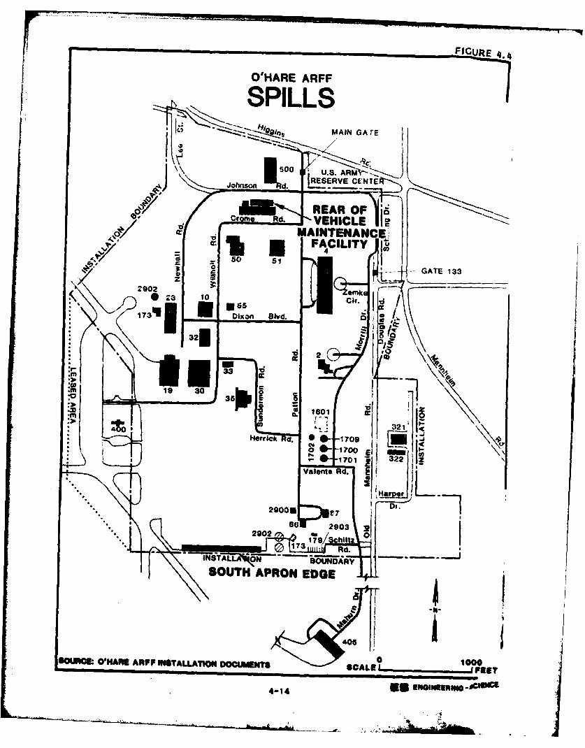
FIGURE 4.
WHARE ARFF
SPILLS'07 MAIN GATE
-S.-- -AI;RV CE-5---,
, * Rd q VEHICL
2902 ek
173111Dixon Blvd.
* 32f
x 2.A19 30
j 35 z
HerrfcI~ a. -1709 iic" I a 1;00 El
322S0I0 ~ ~ ~ ~ ~ ~ ~ Vlet Adf.RP NTLATO OUMNS10
29006 PEE4-14 5 INIWEEIND#
1 V7
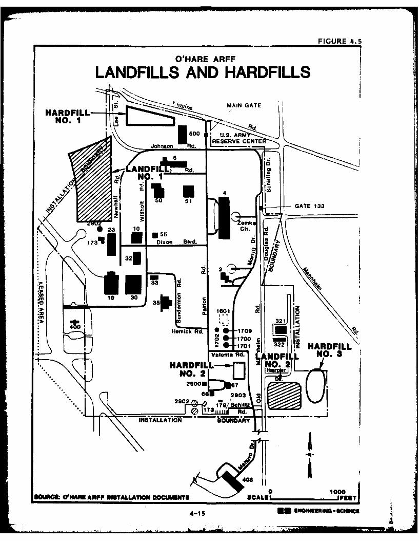
FIGURE 4.5
O'HARE ARFF -
LANDFILLS AND HARDFILLS
;na M.AIN GATEHARDFILL
NO.1I
5 d.
Valenta1in 02I ,NO
SOR~.~UN~mARP TALA~N DCMNSSAE PSc1c*ESNESamc
CLr
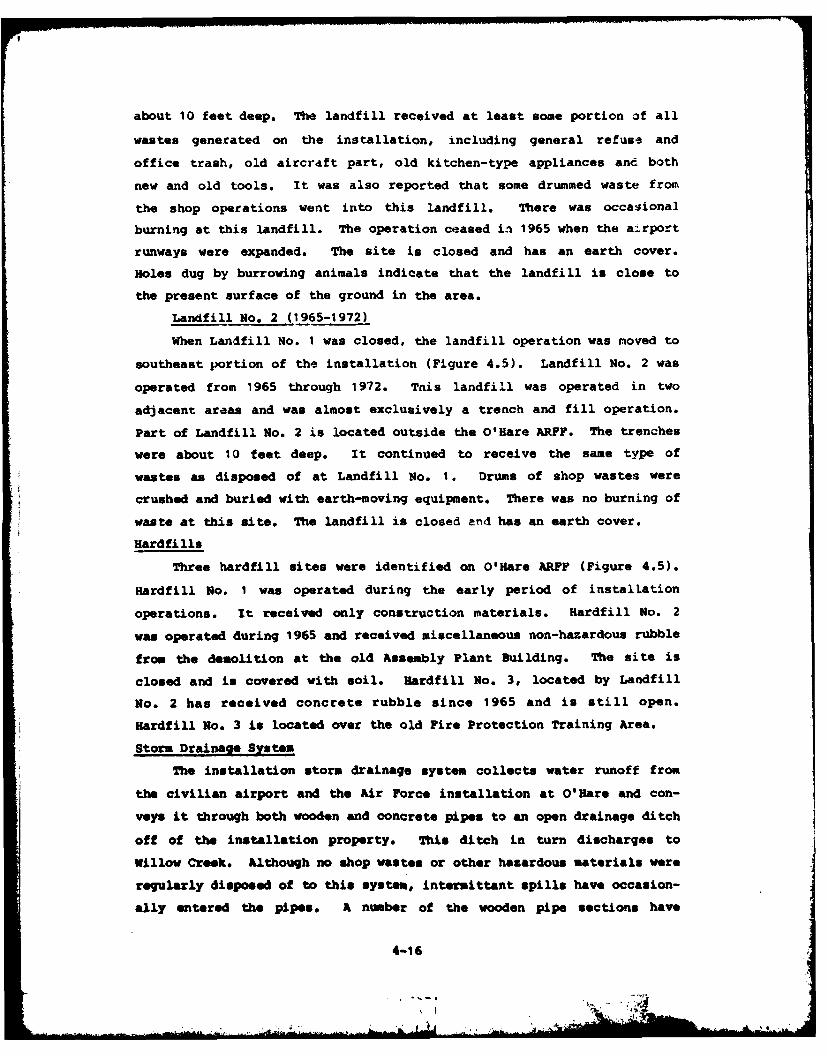
about 10 feet deep. The landfill received at least some portion of all
wastes generated on the installation, including general refuse and
office trash, old aircraft part, old kitchen-type appliances and both
new and old tools. It was also reported that some drummed waste from
the shop operations went into this landfill. There was occasional
burning at this landfill. The operation ceased in 1965 when the a..rport
runways were expanded. The site is closed and has an earth cover.
Holes dug by burrowing animals indicate that the landfill is close to
the present surface of the ground in the area.
Landfill No. 2 (1965-1972)
When Landfill No. 1 was closed, the landfill operation was moved to
southeast portion of the installation (Figure 4.5). Landfill No. 2 was
operated from 1965 through 1972. This landfill was operated in two
adjacent areas and was almost exclusively a trench and fill operation.
Part of Landfill No. 2 is located outside the O'Hare ARFF. The trenches
were about 10 feet deep. It continued to receive the same type of
wastes as disposed of at Landfill No. 1. Drums of shop wastes were
crushed and buried with earth-moving equipment. There was no burning of
waste at this site. The landfill is closed and has an earth cover.
Hardfills
Three hardfill sites were identified on O'Hare ARFF (Figure 4.5).
Hardfill No. I was operated during the early period of installation
operations. It received only construction materials. Hardfill No. 2
was operated during 1965 and received miscellaneous non-hazardous rubble
from the demolition at the old Assembly Plant Building. The site is
closed and is covered with soil. ardfill No. 3, located by Landfill
No. 2 has received concrete rubble since 1965 and is still open.
Hardfill No. 3 is located over the old Fire Protection Training Area.
Storm Drainage System
The installation storm drainage system collects water runoff from
the civilian airport and the Air Force installation at O'Hare and con-
veys it through both wooden and concrete pipes to an open drainage ditch
off of the installation property. This ditch in turn discharges to
Willow Creek. Although no shop wastes or other hazardous materials were
regularly disposed of to this system, intermittant spills have occasion-
ally entered the pipes. A number of the wooden pipe sections have
4-16
At1
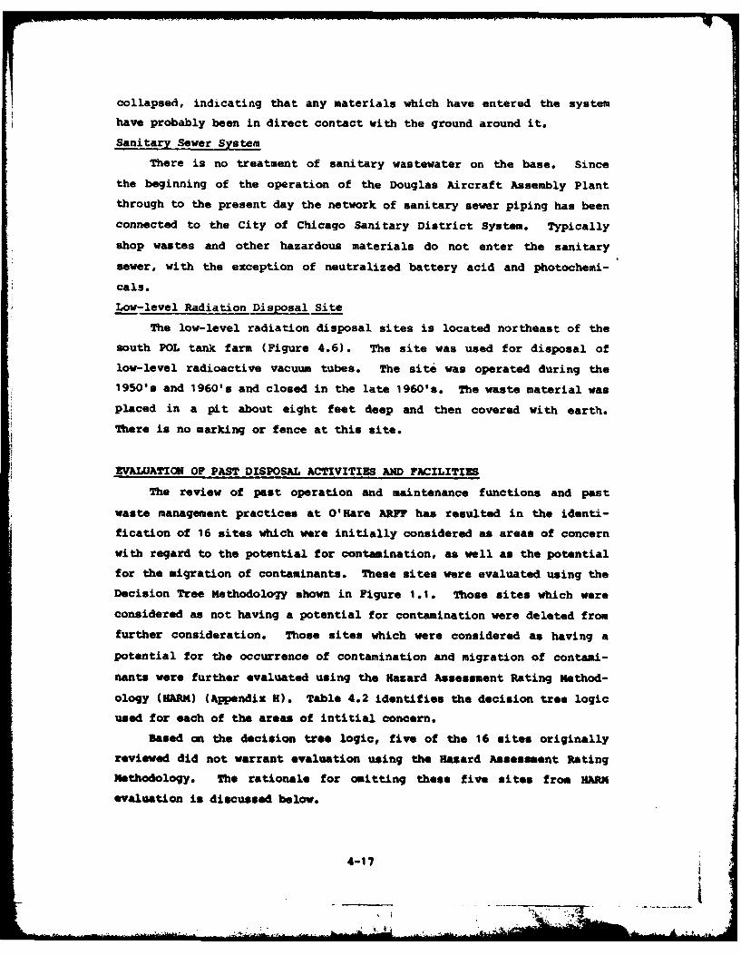
collapsed, indicating that any materials which have entered the system
have probably been in direct contact with the ground around it.
Sanitary Sewer System
There is no treatment of sanitary wastewater on the base. Since
the beginning of the operation of the Douglas Aircraft Assembly Plant
through to the present day the network of sanitary sewer piping has been
connected to the City of Chicago Sanitary District System. Typically
shop wastes and other hazardous materials do not enter the sanitary
sewer, with the exception of neutralized battery acid and photochemi-
cals.
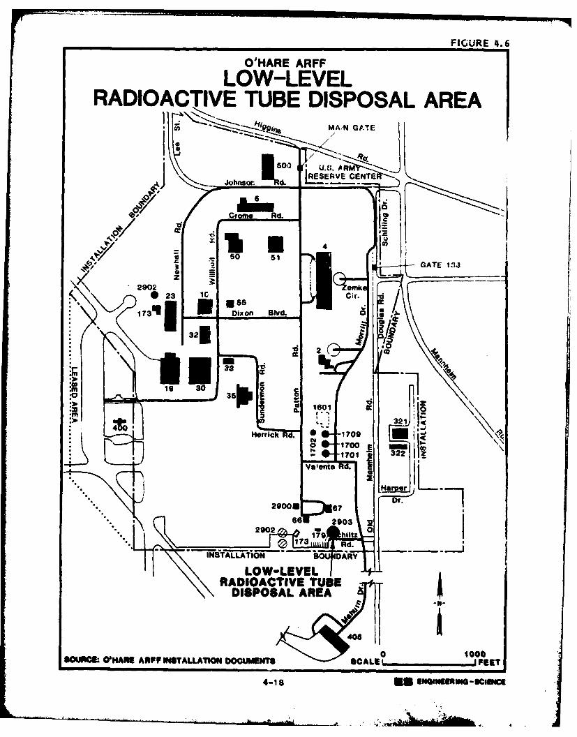
Low-level Radiation Disposal Site
The low-level radiation disposal sites is located northeast of the
south POL tank farm (Figure 4.6). The site was used for disposal of
low-level radioactive vacuum tubes. The site was operated during the1950's and 1960's and closed in the late 1960's. The waste material was
placed in a pit about eight feet deep and then covered with earth.
There is no marking or fence at this site.
EVALUATION OF PAST DISPOSAL ACTIVITIES AND FACILITIES
The review of past operation and maintenance functions and past
waste management practices at O'Hare ARF has resulted in the identi-
fication of 16 sites which were initially considered as areas of concern
with regard to the potential for contamination, as well as the potential
for the migration of contaminants. These sites were evaluated using theDecision Tree Methodology shown in Figure 1 o.1 Those sites which wereconsidered as not having a potential for contamination were deleted fromfurther consideration. Those sites which were considered as having a
potential for the occurrence of contamination and migration of contami-
nants were further evaluated using the Hazard Assessment ating Method-
ology (HARM) (Appendix H). Table 4.2 identifies the decision tree logic
used for each of the areas of intitial concern.
Based on the decision tree logic, five of the 16 sites originallyreviewed did not warrant evaluation using the Hazard Assessment Rating
Methodology. The rationale for omitting these five sites from HARK
evaluation is discussed below.
4-17 4
O'HARE ARFF FGR .
70 .6ALOW-LEVELRADIOACTIVE TUBE DISPOSAL AREA
hip. MA;N GATE
00 LU.b A RMjRESERVE CEN4T
4/"sor Cr d ka 00
f 211 50 5 GATE 1.13
290 z eomk3~ ______
.6- Dix on Blvd.
* 32fw .0
19 30*z - d
a0 1601
321*40Horc 0 1709
valenta
29000 67 D.
lNTLLA 60DARY
LOW-LEVEIRADIOACTIVE TUBE
DISPOSAL AREA
a 1000souRCE OH"Afh ARFF R4STALLATION DOCUMENTS SCALE _____F EET
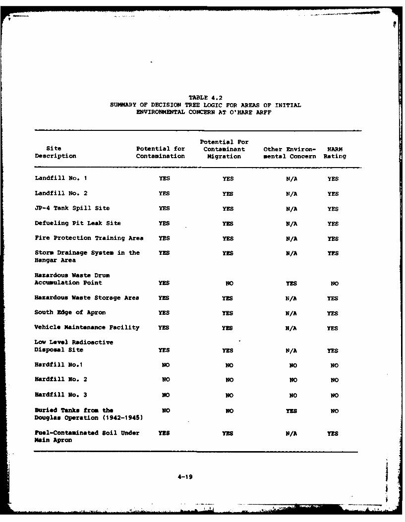
TABLE 4.2SUMMARY OF DECISION TREE LOGIC FOR AREAS OF INITIAL
ENVIRONMENTAL CONCERN AT O'HARE ARFF
Potential ForSite Potential for Contaminant Other Environ- HARM
Description Contamination Migration mental Concern Rating
Landfill No. I YES YES N/A YES
Landfill No. 2 YES YES N/A YES
JP-4 Tank Spill Site YES YES N/A YES
Defueling Pit Leak Site YES YES N/A YES
Fire Protection Training Area YES YES N/A YES
Storm Drainage System in the YES YES N/A YESHangar Area
Hazardous Waste Drum
Accumulation Point YES NO YES NO
Hazardous Waste Storage Area YES YES N/A YES
South Edge of Apron YES YES N/A YES
Vehicle Maintenance Facility YES YES N/A YES
Low Level RadioactiveDisposal Site YES YES N/A YES
Hardfill No.1 NO NO NO NO
Hardfill No. 2 NO NO NO NO
Hmardfill No. 3 NO NO NO NO
Buried Tanks from the NO NO YES NODouglas Operation (1942-1945)
Fuel-Contaninated Soil Under YES YES N/A YESMain Apron
4-19
!k
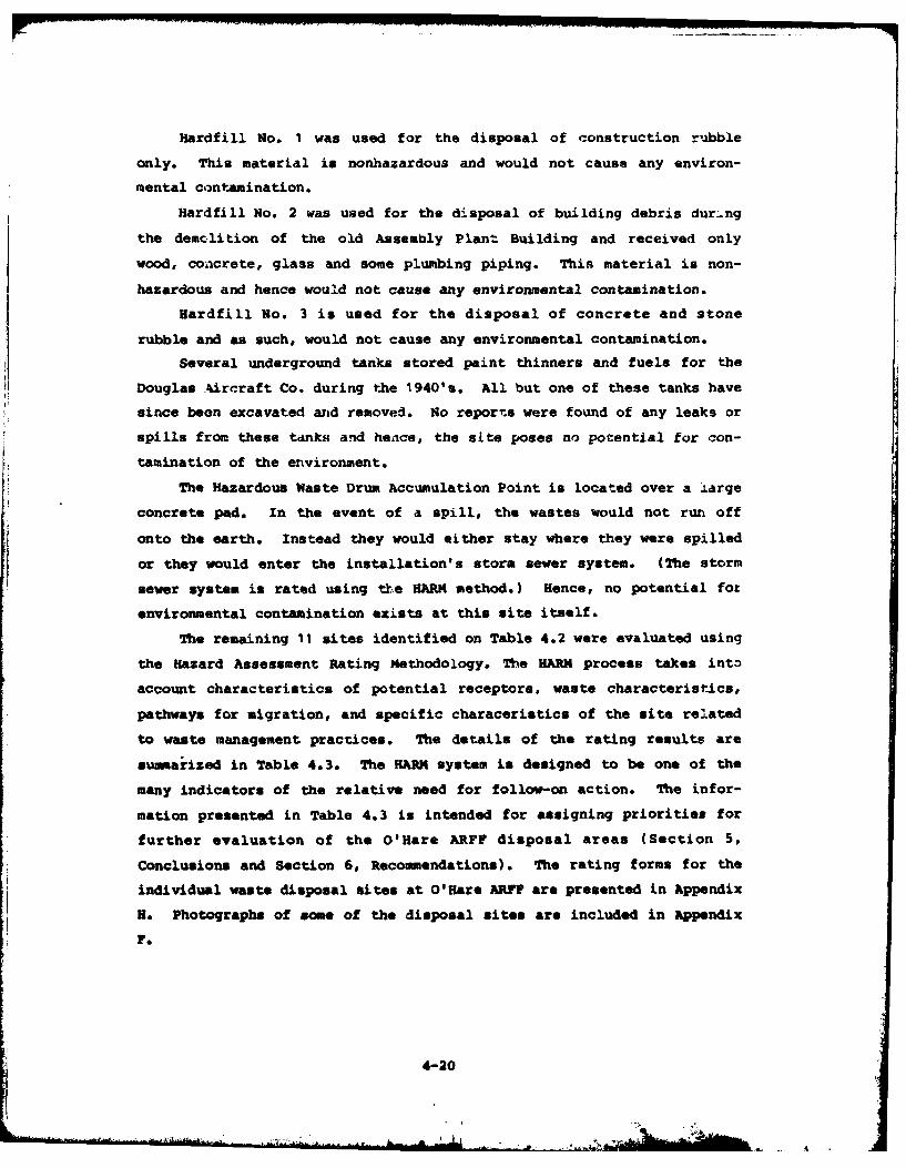
Hardfill No. I was used for the disposal of construction rubble
only. This material is nonhazardous and would not cause any environ-
mental contamination.
Hardfill No. 2 was used for the disposal of building debris dur.ng
the demolition of the old Assembly Plant Building and received only
wood, concrete, glass and some plumbing piping. This material is non-
hazardous and hence would not cause any environmental contamination.
Hardfill No. 3 is used for the disposal of concrete and stone
rubble and as such, would not cause any environmental contamination.
Several underground tanks stored paint thinners and fuels for the
Douglas Aircraft Co. during the 1940's. All but one of these tanks have
since been excavated and removed. No reports were found of any leaks or
spills from these tanks and hence, the site poses no potential for con-
tamination of the environment.
The Hazardous Waste Drum Accumulation Point is located over a large
concrete pad. In the event of a spill, the wastes would not run off
onto the earth. Instead they would either stay where they were spilled
or they would enter the installation's storm sewer system. (The storm
sewer system is rated using tk.e HARM method.) Hence, no potential for
environmental contamination exists at this site itself.
The remaining 11 sites identified on Table 4.2 were evaluated using
the Hazard Assessment Rating Methodology. The HARM process takes into
account characteristics of potential receptors, waste characteristics,
pathways for migration, and specific characeristics of the site related
to waste management practices. The details of the rating results are
suamarized in Table 4.3. The HARM system is designed to be one of the
many indicators of the relative need for follow-on action. The infor-
mation presented in Table 4.3 is intended for assigning priorities for
further evaluation of the O'Hare ARFF disposal areas (Section 5,
Conclusions and Section 6, Recommendations). The rating forms for the
individual waste disposal sites at O'Hare ARFF are presented in Appendix
H. Photographs of some of the disposal sites are included in Appendix
F.
IJ~~i' 4-20,
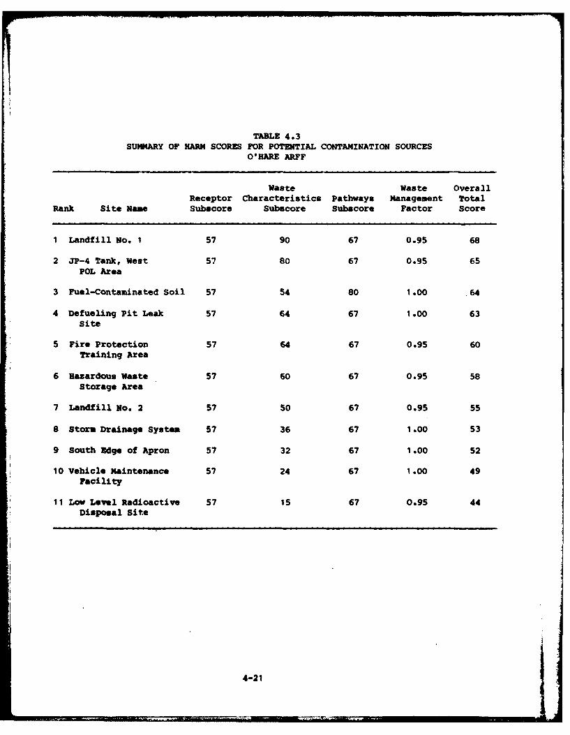
TABLE 4.3SUMMARY OF HARM SCORES FOR POTENTIAL CONTAMINATION SOURCES
O'HARE ARFF
Waste Waste OverallReceptor Characteristics Pathways Management Total
Rank Site Name Subscore Subscore Subscore Factor Score
1 Landfill No. 1 57 90 67 0.95 68
2 JP-4 Tank, West 57 80 67 0.95 65POL Area
3 Fuel-Contaminated Soil 57 54 80 1.00 .64
4 Defueling Pit Leak 57 64 67 1.00 63site
5 Fire Protection 57 64 67 0.95 60Training Area
6 Hazardous Waste 57 60 67 0.95 58Storage Area
7 Landfill No. 2 57 50 67 0.95 55
8 Storm Drainage System 57 36 67 1 .00 53
9 South Edge of Apron 57 32 67 1 .00 52
10 Vehicle Maintenance 57 24 67 1.00 49Facility
11 Low Level Radioactive 57 15 67 0.95 44Disposal Sit.e
4-21
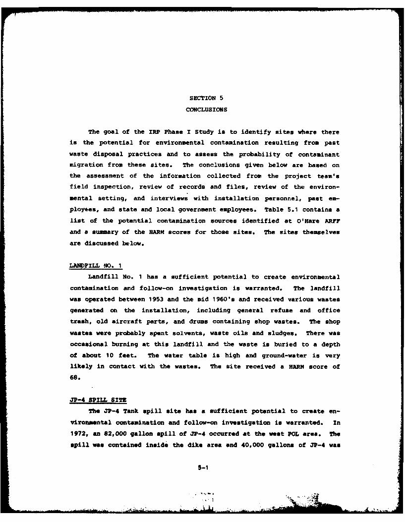
SECTION 5
CONCLUSIONS
The goal of the IRP Phase I Study is to identify sites where there
is the potential for environmental contamination resulting from past
waste disposal practices and to assess the probability of contaminant
migration from these sites. The conclusions given below are based on
the assessment of the information collected from the project team's
field inspection, review of records and files, review of the environ-
mental setting, and interviews with installation personnel, past em-
ployees, and state and local government employees. Table 5.1 contains a
list of the potential contamination sources identified at O'Hare ARFF
and a summary of the HARM scores for those sites. The sites themselves
are discussed below.
LANDFILL eO. 1
Landfill No. 1 has a sufficient potential to create environmental
contamination and follow-on investigation is warranted. The landfill
was operated between 1953 and the mid 1960's and received various wastes
generated on the installation, including general refuse and office
trash, old aircraft parts, and drums containing shop wastes. The shop
wastes were probably spent solvents, waste oils and sludges. There was
occasional burning at this landfill and the waste is buried to a depth
of about 10 feet. The water table is high and ground-water is very
likely in contact with the wastes. The site received a HARM score of
68.
JP-4 SPILL SITE
The JP-4 Tank spill site has a sufficient potential to create en-
vironmental contamination and follow-on investigation is warranted. In
1972, an 82,000 gallon spill of JP-4 occurred at the West POL area. The
spill was contained inside the dike area and 40,000 gallons of JP-4 was
5-1
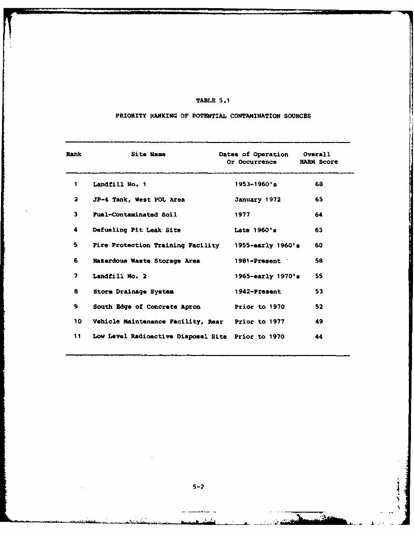
TABLE 5.1
PRIORITY RANKING OF POTENTIAL CONTAMINATION SOURCES
Rank Site Name Dates of Operation OverallOr Occurrence HARM Score
1 Landfill No. 1 1953-1960's 68
2 JP-4 Tank, West POL Area January 1972 65
3 Fuel-Contaminated Soil 1977 64
4 Defueling Pit Leak Site Late 1960's 63
5 Fire Protection Training Facility 1955-early 1960's 60
6 Hazardous Waste Storage Area 1981-Present 58
7 Landfill No. 2 1965-early 1970's 55
8 Storm Drainage System 1942-Present 53
9 South Edge of Concrete Apron Prior to 1970 52
10 Vehicle Maintenance Facility, Rear Prior to 1977 49
11 Low Level Radioactive Disposal Site Prior to 1970 44
5-2
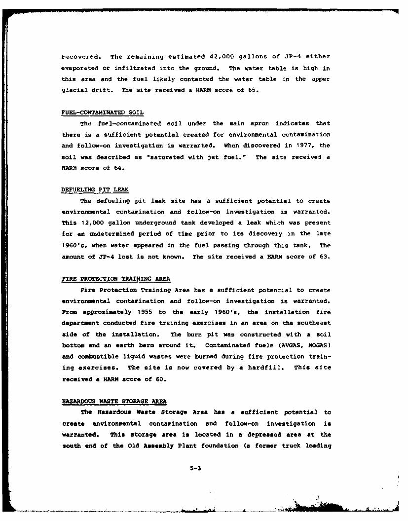
recovered. The remaining estimated 42,000 gallons of JP-4 either
evaporated or infiltrated into the ground. The water table is high in
this area and the fuel likely contacted the water table in the upper
glacial drift. The site received a HARM score of 65.
FUEL-CONTAMINATED SOIL
The fuel-contaminated soil under the main apron indicates that
there is a sufficient potential created for environmental contamination
and follow-on investigation is warrarted. When discovered in 1977, the
soil was described as "saturated with jet fuel." The site received a
HARM4 score of 64.
DEFUELING PIT LEAK
The defueling pit leak site has a sufficient potential to create
environmental contamination and follow-on investigation is warranted.
This 12,000 gallon underground tank developed a leak which was present
for an undetermined period of time prior to its discovery In the late
1960's, when water appeared in the fuel passing through this tank. The
amount of JP-4 lost is not known. The site received a HARM score of 63.
FIRE PROTECTION TRAINING AREA
Fire Protection Training Area has a sufficient potential to create
environmental contamination and follow-on investigation is warranted.
From approximately 1955 to the early 1960's, the installation fire
department conducted fire training exercises in an area on the southeast
side of the installation. The burn pit was constructed with a soil
bottom and an earth berm around it. CQntaminated fuels (AVGAS, MOGAS)
and combustible liquid wastes were burned during fire protection train-
ing exercises. The site is now covered by a hardfill. This site
received a HARM score of 60.
HAZARDOUS WASTE STORAGE ARE
The Hazardous Waste Storage Area has a sufficient potential to
create environmental contamination and follow-on investigation is
warranted. This storage area is located in a depressed area at the
south end of the Old Assembly Plant foundation (a former truck loading
5-3

TABLE 4.3SUMMARY OF HARM SCORES FOR POTENTIAL CONTAMINATION SOURCES
O'HARE ARFF
Waste Waste OverallReceptor Characteristics Pathways Management Total
Rank Site Name Subscore Subscore Subscore Factor Score
I Landfill No. 1 57 90 67 0.95 68
2 JP-4 Tank, West 57 80 67 0.95 65
POL Area
3 Fuel-Contaminated Soil 57 54 80 1.00 64
4 Defueling Pit Leak 57 64 67 1.00 63Site
5 Fire Protection 57 64 67 0.95 60Training Area
6 Hazardous Waste 57 60 67 0.95 58Storage Area
7 Landfill No. 2 57 50 67 0.95 55
8 Storm Drainage System 57 36 67 1.00 53
9 South Edge of Apron 57 32 67 1.00 52
10 Vehicle Maintenance 57 24 67 1.00 49Facility
11 Low Level Radioactive 57 15 67 0.95 44Disposal Site
___4-21
12

SECTION 5
CONCLUS IONS
The goal of the IRP Phase I Study is to identify sites where there
is the potential for environmental contamination resulting from past
waste disposal practices and to assess the probability of contaminant
migration from these sites. The conclusions given below are based on
the assessment of the information collected from the project team's
field inspection, review of records and files, review of the environ-
mental setting, and interviews with installation personnel, past em-
ployees, and state and local government employees. Table 5.1 contains a
list of the potential contamination sources identified at O'Hare ARFF
and a summary of the EARM scores for those sites. The sites themselves
are discussed below.
LANDFILL NO. 1
Landfill No. I has a sufficient potential to create environmental
contamination and follow-on investigation is warranted. The landfill
was operated between 1953 and the mid 1960's and received various wastes
generated on the installation, including general refuse and office
trash, old aircraft parts, and drums containing shop wastes. The shop
wastes were probably spent solvents, waste oils and sludges. There was
occasional burning at this landfill and the waste is buried to a depth
of about 10 feet. The water table is high and ground-water is very
likely in contact with the wastes. The site received a HARM score of
68.
JP-4 SPILL SITE
The JP-4 Tank spill site has a sufficient potential to create en-
vironmental contamination and follow-on investigation is warranted. In
1972, an 82,000 gallon spill of JP-4 occurred at the west POL area. The
spill was contained inside the dike area and 40,000 gallons of JP-4 was
: 5-1
's L__
_ _ _ _ k
.........
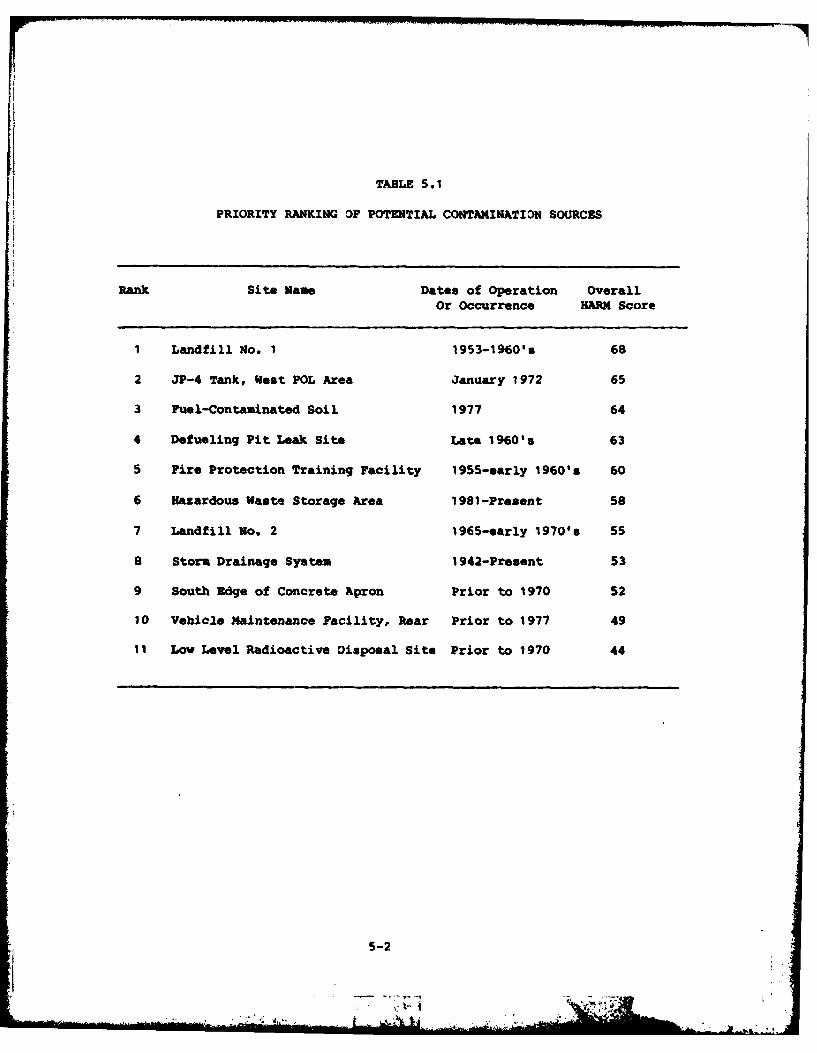
TABLE 5.1
PRIORITY RANKING OF POTENTIAL CONTAMINATION SOURCES
Rank Site Name Dates of Operation OverallOr Occurrence HARM Score
I Landfill No. 1 1953-1960's 68
2 JP-4 Tank, West POL Area January 1972 65
3 Fuel-Contaminated Soil 1977 64
4 Defueling Pit Leak Site Late 1960's 63
5 Fire Protection Training Facility 1955-early 1960's 60
6 Hazardous Waste Storage Area 1981-Present 58
7 Landfill No. 2 1965-early 1970's 55
a Storm Drainage System 1942-Present 53
9 South Edge of Concrete Apron Prior to 1970 52
10 Vehicle Maintenance Facility, Rear Prior to 1977 49
11 Low Level Radioactive Disposal Site Prior to 1970 44
5-2
recovered. The remaining estimated 42,000 gallons of JP-4 either
evaporated or infiltrated into the ground. The water table is high in
this area and the fuel likely contacted the water table in the upper
glacial drift. The site received a HARM score of 65.
FUEL-CONTAMINATED SOIL
The fuel-contaminated soil under the main apron indicates that
there is a sufficient potential created for environmental contamination
and follow-on investigation is warranted. When discovered in 1977, the
soil was described as "saturated with jet fuel." The site received a
HARM score of 64.
DEFUELING PIT LEAK
The defueling pit leak site has a sufficient potential to create
environmental contamination and follow-on investigation is warranted.
This 12,000 gallon underground tank developed a leak which was present
for an undetermined period of time prior to its discovery in the late
1960's, when water appeared in the fuel passing through this tank. The
amount of JP-4 lost is not known. The site received a HARM score of 63.
FIRE PROTECTION TRAINING AREA
Fire Protection Training Area has a sufficient potential to create
environmental contamination and follow-on investigation is warranted.
From approximately 1955 to the early 1960's, the installation fire
department conducted fire training exercises in an area on the southeast
side of the installation. The burn pit was constructed with a soil
bottom and an earth berm around it. Contaminated fuels (AVGAS, MOGAS)
and combustible liquid wastes were burned during fire protection train-
ing exercises. The site is now covered by a hardfill. This site
received a HARM score of 60.
HAZARDOUS WASTE STORAGE AREA
The Hazardous Waste Storage Area has a sufficient potential to
create environmental contamination and follow-on investigation is
warranted. This storage area is located in a depressed area at the
south end of the Old Assembly Plant foundation (a former truck loading
5S-3 i a
area). The soil in this storage area was darker than normal, indicating
that past spills have occurred. This site received a HARM score of 58.
LANDFILL NO. 2
Landfill No. 2 has a sufficent potential to create environmental
contamination and follow-on investigation is warranted. This landfill
was in operation from the mid 1960's through 1972 and was operated in
two adjacent areas in a trench and fill manner. A portion of this
landfill is located outside of O'Hare ARFF property. Trenches were
about 10 feet deep. It received general refuse, office trash and some
shop wastes. Some drums of shop wastes were crushed with earth moving
equipment. There was no burning of waste at this site. The landfill is
closed and covered. The water table is high and ground water is very
likely in contact with the wastes. The site received a HARM score of
55.
STORM DRAINAGE SYSTEM NEAR HANGARS
The Storm Drainage System in the Aircraft hangar area has a suf-
ficient potential to create environmental contamination and follow-on
investigation is warranted. The system in this area has probably
received shop wastes from the hangars. Also, liquid hazardous wastes
are accumulated in an area which drains directly into this wood- and
concrete-pipe system. The system received a HARM score of 53.
SOUTH EDGE OF APRON
The south edge of the main concrete apron has a sufficient poten-
tial to create environmental contamination and follow-on investigation
is warranted. This area was occasionally used as a dumping area for
small quantities of liquid wastes from the shop* in the 1950's and
1960's. A stormwater drainage ditch runs parallel to the edge, about
ten feet away. During the site visit, no environmental stress was
observed in this area. The site received a HARM score of 52.
VEHICLE MAINTENANCE FACILITY
The rear of the vehicle maintenance facility has an insufficient
potential to create environmental contamination and no follow-on
5-4
investigation is warranted. Motor oil was dumped on the ground north of
Building No. 5 from the early 1950's until about 1975. The area behind
the building has been covered over by a concrete vehicle parking lot.
The contaminated soil may have been removed when the parking lot was
built. The site received a HAPM score of 49.
LOW-LEVEL RADIOACTIVE DISPOSAL SITE
The low-level radioactive disposal site has an insufficient po-
tential to create environmental contamination and no follow-on investi-
gation is warranted. This area was used for the disposal of vacuum
tubes during the 1950's and the 19601s. The site received a HARM score
of 44.
5-5
p
SECTION 6
RECOMMENDATIONS
Eleven sites were identified at O'Hare ARFF as having the potential
for environmental contamination and have been evaluated using the HARM
system. This evaluation assessed their relative potential for environ-
mental contamination and along with relevarnt site specific information
identified those sites where further study and monitoring may be neces-
sary. Nine of the sites were determined to have sufficient evidence to
indicate the potential for environmental contamination. Additional data
concerning these sites will be required in order to clearly ascertain
whether or not these sites have contributed environmental contamination.
Therefore, the following recommendations have been developed for each of
the nine sites. There was insufficient evidence on the other two sites
to warrant further investigation.
PHASE II MONITORING RECOMMENDATIONS
The following recommendations are made to further assess the
potential for environmental contamination from waste disposal areas at
O'Hare ARFF. The recommended actions are generally one-time sampling
programs to determine if contamination does exist at the site. If con-
tamination is identified, the sampling program may need to be expanded
to further define the extent of contamination.
Geophysical surveys, consisting of electrical resistivity, electro-
magnetic and/or magnetometer techniques, are recommended prior to any
well installations to attempt to delineate the horizontal and vertical
extent of the site, subsurface leachate plumes migrating from the site,
and subsurface stratigraphy including the hardpan formation. The alter-
native approach to geophysical testing would be the conventional tech-
nique to test well drilling and ground-water sampling. The cost benefit
6-1
......... _A
of geophysical surveys over test drilling can be understood by compari-
sons of time, cost and data availability. Table 6.1 presents genera]
guidelines for the use of certain geophysical techniques.
The recommended monitoring program for Phase II is summarized ir
Table 6.2.
1) Landfill No. 1 has a sufficient potential to create environmental
contamination and monitoring of this site is recommended. A geo-
physical survey should be conducted to define the landfill
boundaries and depth, and identify any leachate plume. Based on
the results of the geophysical survey, one upgradient and 3 down-
gradient monitoring wells should be installed. Wells should be
constructed using 3" Schedule 40 PVC, screened into the first sand
and gravel lens (20' to 30' deep). Sample these wells and analyze
for pH, total dissolved solids, total organic halogen, total
organic carbon, oil and grease, and phenol.
2) The JP-4 Tank Dike Spill Site has a sufficient potential to create
environmental contamination and further monitoring of this site is
recommended. A geophysical survey should be conducted around the
tank farm to identify any JP-4 plume. Conduct a continuous core
sampling in the dike area extended to the first sand and gravel
lens and observe if any JP-4 is present. Then perform a water
extract on 3 soil samples and analyze for oil and grease, and total
organic carbon.
3) The Fuel-contaminated Soil area indicates that there is a suf-
ficient potential to create environmental contamination and further
monitoring of this site is recommended. A geophysical survey
should be conducted around the area to define the extent of the
fuel plume and to locate its source, if possible. Conduct a
continuous core sampling as near to the sites as possible, extended
to the first sand and gravel lens (20' to 30' deep) and observe if
any JP-4 is present. Then perform a water extract on 3 soil samp-
les and analyze for oil and grease and total organic carbon. If a
6-2 I * 4
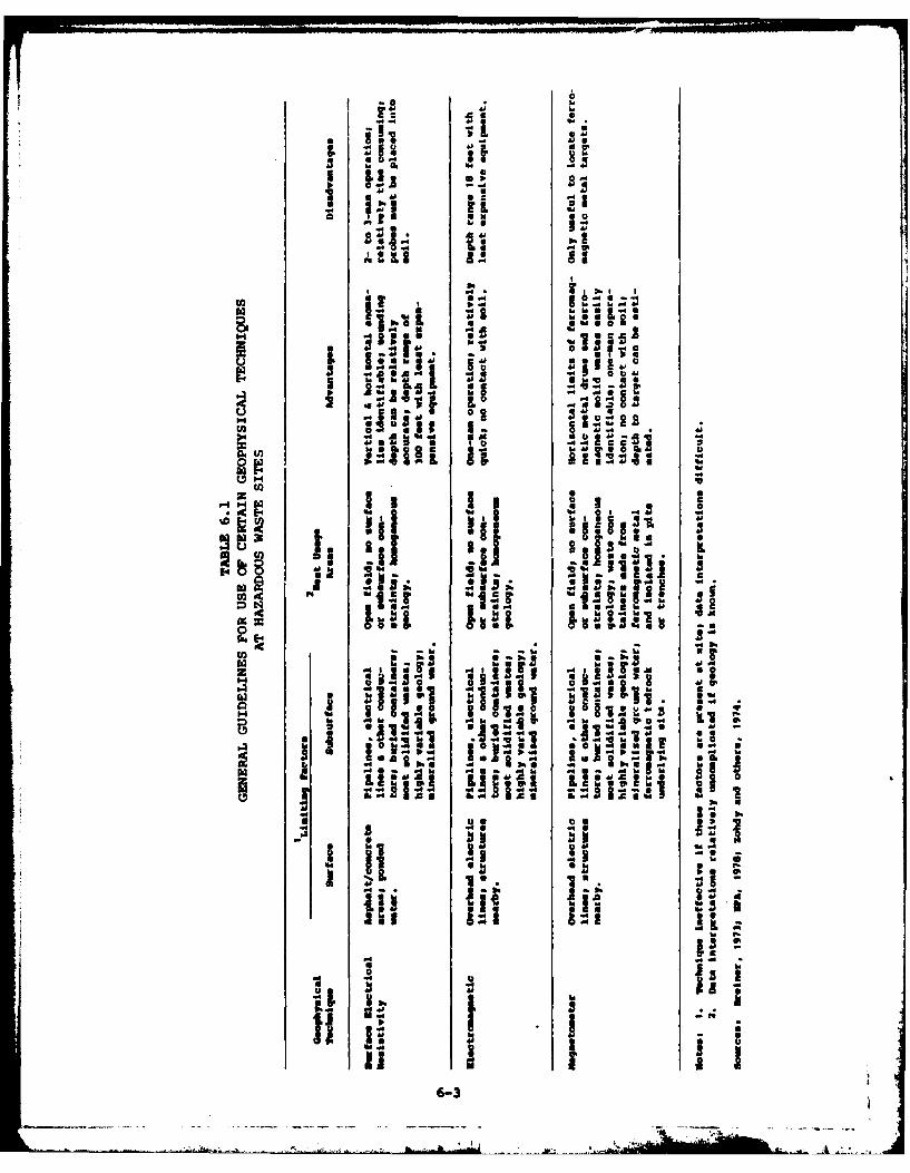
6
'"
-So
I.E..46
=ibu- led '6!-
.' i1 3 +4 04'I
I is: i I :
to3
taa
BE -P il I 1
U) - ~ 44
b~hU 6.4
MUPo 9.
* ~ '~ ~ ii
464
shh40 a0[
6-3m;
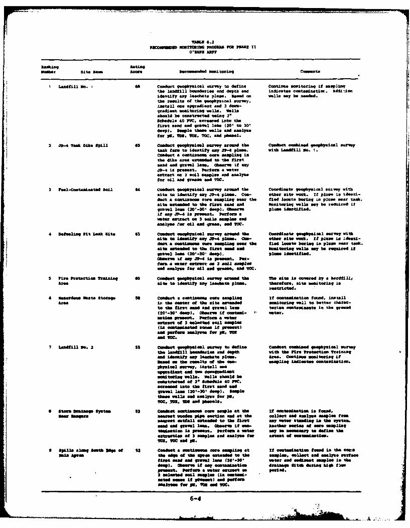
11.51 6.23SCOEiN Nna?!XM O M lAC Ma 101. 11E
RankingRatingmembr site meO score Recomended monitoring Comments
I Landfill No. i Go Conduct geophysical survey to define Continue monitoring if amplingthe landfill bounawieg and depth end indicates contaminatior. * Adi-iceidentify any loechate plume. based a wells ay be needed.the results of the geophysical survey,install ems upgradient and 3 dn-gradient monitorinlg Vella. wellsshould be conatructed uaing 31Schedule 40 PVC, screeneid into thefirst sand and gravel less (201 to 301deep). Samle these well. ad analyse
.1 for Pa, Mo. M~. iCC, and phmol.
2 4P-4 lank Dike Spill 6a conduct geophysical survey aoud the Conduct comied geophysical surveytank farm to identify any .11-4 plane. With Landfill Wo. 1.conduct a continuums comtsampling inthe dike area extended to the firstsand and gravel leam. Observe Lf any33-4 is Present. Perform a waterextract em 3 mail smples and analysefor oil and growne sAd 2VC.
3 Tual-Coataminatad Soil 64 Conduct geophysical survey around the Coordinate geophysical muolvay withsite to identify any 31" plume. C- other sits work. if plume is ideaad-duct a continuous ewre ampling ason the tied locate baring in pluns near tank.site extended to the first sd and Isonitoring wells way be reuited itgravel lame (201-N0 deep). Observe plae identified.if any .11-4 is present. Perf orm awater etract on 3 mails samplas andanalyse Por oil and greas, and 10C.
4 Datueling Pit Leak Site 63 Cocet 4eophysical survey aroud ase Coordnate gaphi cel McrVey with@its to identify say a1-4 plume. cam- other sits work. If plums ia Idumti-duct a cutimems ouws sampling near the fied loeat* boring in plum near tank.sift extended to the first send and mitoring well. my he required ifgrovel. les (201-30 deep). plam Identified.Obsmv if any 31-4 is pIet Per-to" a eer, oetrat as 3 , Salsap
5 Pirs Protection 2raining 60 Conduct geophysical survey arun the The site is covered by a hardfla,ATea site to identify any isathats plane. therefore, mite moitoring Is
restricted.
6 asardome Waste Storage so conduct a continua"s comu smpling If contamination fomund, ins tallArea imi the caster of the cI to extended monitoring vell to better charac-
to the firet sand and gravel lam terie cotminants in the ground(20'-301 deep). Obhasm If contami- eter.matios preset. Pertos= a waeretrust of 3 selected soil sam3ae(in ontaminated soewe if presnt)and poerrm alyste for PE,IOend 10M.
7 Landfill 30. 2 55 Comt geughysical srvey to dsfine Conduct combined geophysical surveythe landfill bedrme and depth with the Fire protection trainingand Identify asy leachete plum. Area. ontinue msctoering itBox"d me the vomsut of the quo- sampling indicesa onteaiation.physical. survey, install oeupgradiant ad to dowagradieftamornterig wl"s. Wll. should heconstructed of 3* Schedule 40 PV,areemed into the first mand andgravel lees (201-NO deep). isauthese well. and analyse for pg.IcO, 2M, IN and phenol.
9 Stara Drainage System S3 Conduct estieme core eswe at the if oemtasndatieft in too"m."Me ane" smaet woodes pipe section sSd at the ollect and analyse samples f rom
neareet outtall extended to the first any meter Steeding is the system.sand emS gravel loes. Observe If camn- Asothr sofien of owes Samplingtsastiob in present. Perform a water my be assumeary to define theextraction of N Magles and analyze for extent of es .ties.2MU, M0 sS p6.
9 Spill. along South Udge of SN Conduct a estinse core sampling at it loeuts"Ntiom found in the comeNais Apre the edge of tMo apron extended to the saaplee * collect and &only%* surface
first cged amd graowl lss (2O'-2, water and Sedimnst seoplee In theSeep). Observe if eany ocasaiatiom drainage dita during high flowprecas. performs mewter extract as period.N Slected MAmes.aplas (is mUf--
ated seems if preset) A peefermenels for Pm, Ift end WO.
6-4
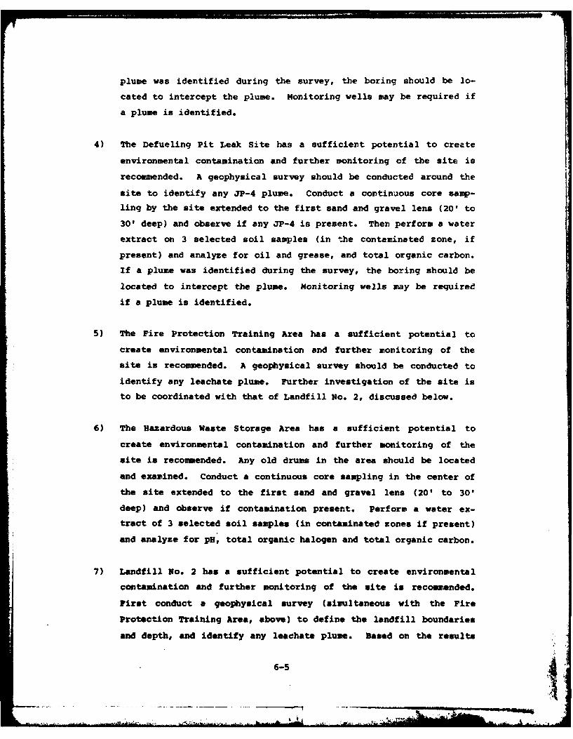
plume was identified during the survey, the boring should be lo-
cated to intercept the plume. Monitoring wells may be required if
a plume is identified.
4) The Defueling Pit Leak Site has a sufficient potential to create
environmental contamination and further monitoring of the site is
recommended. A geophysical survey should be conducted around the
site to identify any JP-4 plume. Conduct a continuous core samp-
ling by the site extended to the first sand and gravel lens (20' to
30' deep) and observe if any JP-4 is present. Then perform a water
extract on 3 selected soil samples (in the contaminated zone, if
present) and analyze for oil and grease, and total organic carbon.
If a plume was identified during the survey, the boring should be
located to intercept the plume. Monitoring wells may be required
if a plume is identified.
5) The Fire Protection Training Area has a sufficient potential to
create environmental contamination and further monitoring of the
site is recommended. A geophysical survey should be conducted to
identify any leachate plume. Further investigation of the site is
to be coordinated with that of Landfill No. 2, discussed below.
6) The Hazardous Waste Storage Area has a sufficient potential to
create environmental contamination and further monitoring of the
site is recommended. Any old drums in the area should be located
and examined. Conduct a continuous core sampling in the center of
the site extended to the first sand and gravel lens (20' to 30'
deep) and observe if contamination present. Perform a water ex-
tract of 3 selected soil samples (in contaminated zones if present)
and analyze for pH, total organic halogen and total organic carbon.
7) Landfill No. 2 has a sufficient potential to create environmental
contamination and further monitoring of the site is recommended.
First conduct a geophysical survey (simultaneous with the Fire
Protection Training Area, above) to define the landfill boundaries
and depth, and identify any leachate plume. Based on the results
6-5 4-moo.
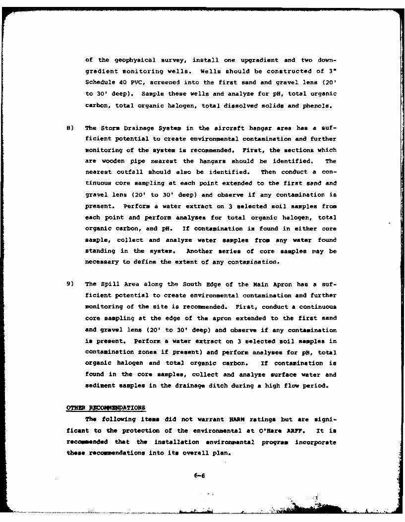
of the geophysical survey, install one upgradient and two down-
gradient monitoring wells. Wells should be constructed of 3"
Schedule 40 PVC, screened into the first sand and gravel lens (20'
to 30' deep). Sample these wells and analyze for pH, total organic
carbon, total organic halogen, total dissolved solids and phenols.
8) The Storm Drainage System in the aircraft hangar area has a suf-
ficient potential to create environmental contamination and further
monitoring of the system is recommended. First, the sections which
are wooden pipe nearest the hangars should be identified. The
nearest outfall should also be identified. Then conduct a con-
tinuous core sampling at each point extended to the first sand and
gravel lens (20' to 30' deep) and observe if any contamination is
present. Perform a water extract on 3 selected soil samples from
each point and perform analyses for total organic halogen, total
organic carbon, and pH. If contamination is found in either core
sample, collect and analyze water samples from any water found
standing in the system. Another series of core samples nay be
necessary to define the extent of any contamination.
9) The Spill Area along the South Edge of the Main Apron has a suf-
ficient potential to create environmental contamination and further
monitoring of the site is recommended. First, conduct a continuous
core sampling at the edge of the apron extended to the first sand
and gravel lens (20' to 30' deep) and observe if any contamination
is present. Perform a water extract on 3 selected soil samples in
contamination zones if present) and perform analyses for pH, total
organic halogen and total organic carbon. If contamination is
found in the core samples, collect and analyze surface water and
sediment samples in the drainage ditch during a high flow period.
OTHER RECOMEMNDATIONS
The following items did not warrant HARM ratings but are signi-
ficant to the protection of the environmental at O'Hare ARFF. It is
recommended that the installation environmental program incorporate
these recommendations into its overall plan.
6-6
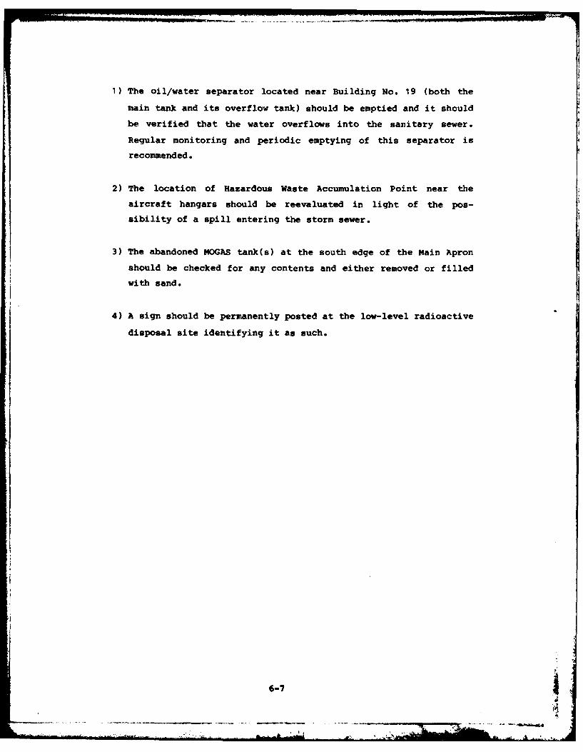
1) The oil/water separator located near Building No. 19 (both the
main tank and its overflow tank) should be emptied and it should
be verified that the water overflows into the sanitary sewer.
Regular monitoring and periodic emptying of this separator is
recommended.
2) The location of Hazardous Waste Accumulation Point near the
aircraft hangars should be reevaluated in light of the pos-
sibility of a spill entering the storm sewer.
3) The abandoned MOGAS tank(s) at the south edge of the Main Apron
should be checked for any contents and either removed or filled
with sand.
4) A sign should be permanently posted at the low-level radioactive
disposal site identifying it as such.
6-7
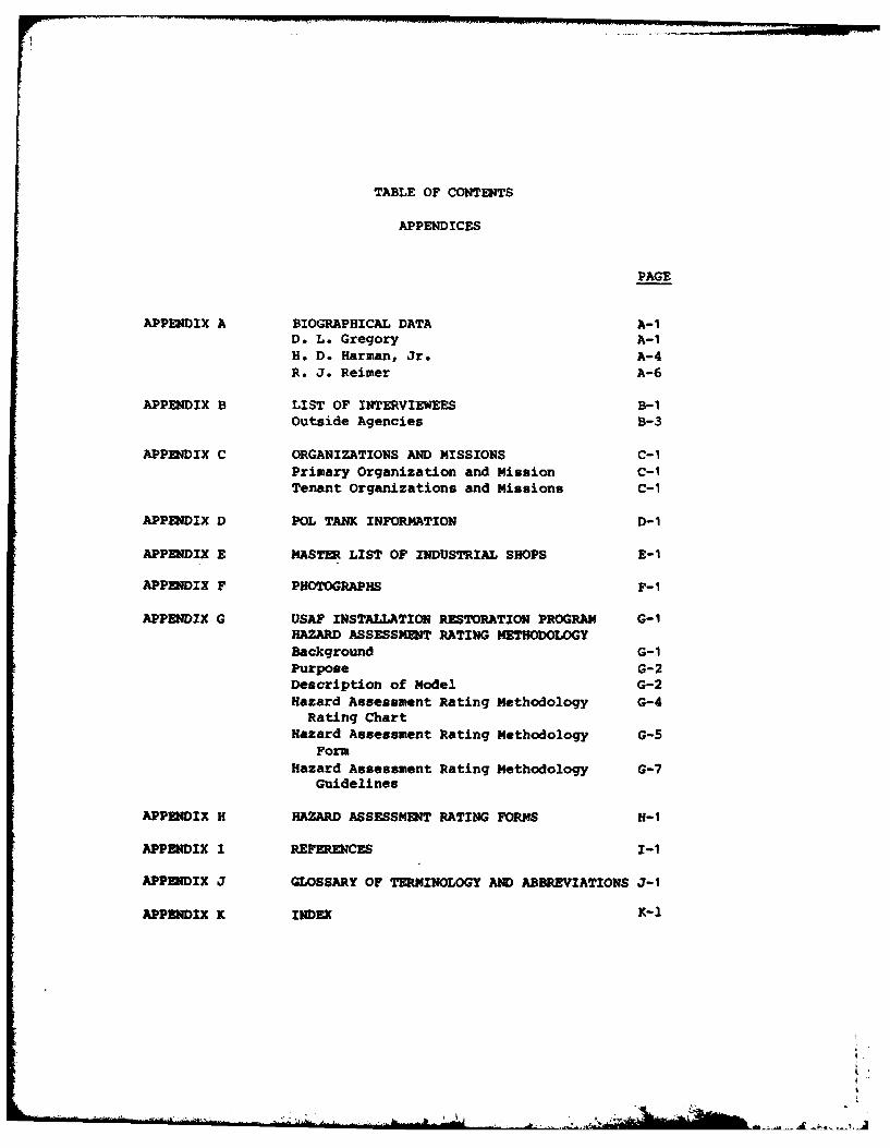
TABLE OF CONTENTS
APPENDICES
PAGE
APPENDIX A BIOGRAPHICAL DATA A-ID. L. Gregory A-iH. D. Harman, Jr. A-4R. J. Reimer A-6
APPENDIX B LIST OF INTERVIEWEES B-iOutside Agencies B-3
APPENDIX C ORGANIZATIONS AND MISSIONS C-iPrimary Organization and Mission C-1Tenant Organizations and Missions C-i
APPENDIX D POL TANK INFORMATION D-1
APPENDIX E MASTER LIST OF INDUSTRIAL SHOPS E-i
APPENDIX F PHOTOGRAPHS F-i
APPENDIX G USAF INSTALLATION RESTORATION PROGRAM G-iHAZARD ASSESSMENT RATING METHODOLOGYBackground G-1Purpose G-2Description of Model G-2Hazard Assessment Rating Methodology G-4
Rating ChartHazard Assessment Rating Methodology G-5
FormHazard Assessment Rating Methodology G-7
Guidelines
APPENDIX H HAZARD ASSESSMENT RATING FORMS H-1
APPENDIX I REFERENCES I-I
APPENDIX J GLOSSARY OF TERMINOLOGY AND ABBREVIATIONS J-1
APPENDIX K INDEX K-1
A
APPENDIX A
BIOGRAPHICAL DATA
D. L. Gregory, Project Manager A-iH. D. Harmaan, Jr. A-4R. J. Reimer A-6
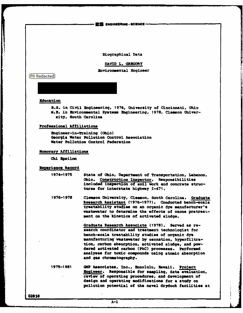
E s - SCIENCE
Biographical Data
DAVID L. GREGORY
Environmental Engineer
Education
B.S. in Civil Engineering, 1976, University of Cincinnati, OhioM.E. in Environmental Syste Engineering, 1978, Clemson Univer-
sity, South Carolina
Professional Affiliations
Engineer-in-Training (Ohio)Georgia Water Pollution Control AssociationWater Pollution Control Federation
Honorary Affiliations
Chi Epsilon
Zzperience Record
1974-1975 State of Ohio, Departmnt of Transportation, Lebanon,
Ohio. Construction Inspector. Responsibilitiesincluded inspection of soil work and concrete struc-tures for interstate highway 1-471.
1976-1978 Clemson University, Clemon, South Carolina. Graduate
Research Assistant (1976-1977). Conducted bench-scaletreatability studies on an organic dye manufacturer'swastewater to determine the effects of ozone pretreat-sent on the kinetics of activated sludge.
Graduate Research Associate (1978). Served as re-search coordinator and treatment technologist forbench-scale treatability studies of organic dyemanufacturing wastawater by ozonation, hyperfiltra-tion, carbon absorption, activated sludge, and pow-dered activated carbon (PAC) processes . Performedanalyses for toxic compounds using atomic absorptionand gas chromatography.
1979-1981 GNP Associates, Inc., Honolulu, Hawaii. ProJectEngineer. Responsible for sampling, data evaluation,review of operating procedures, and developent ofdesign and operating modifications for a study onpollution potential of the naval drydock facilities at
02830A-1
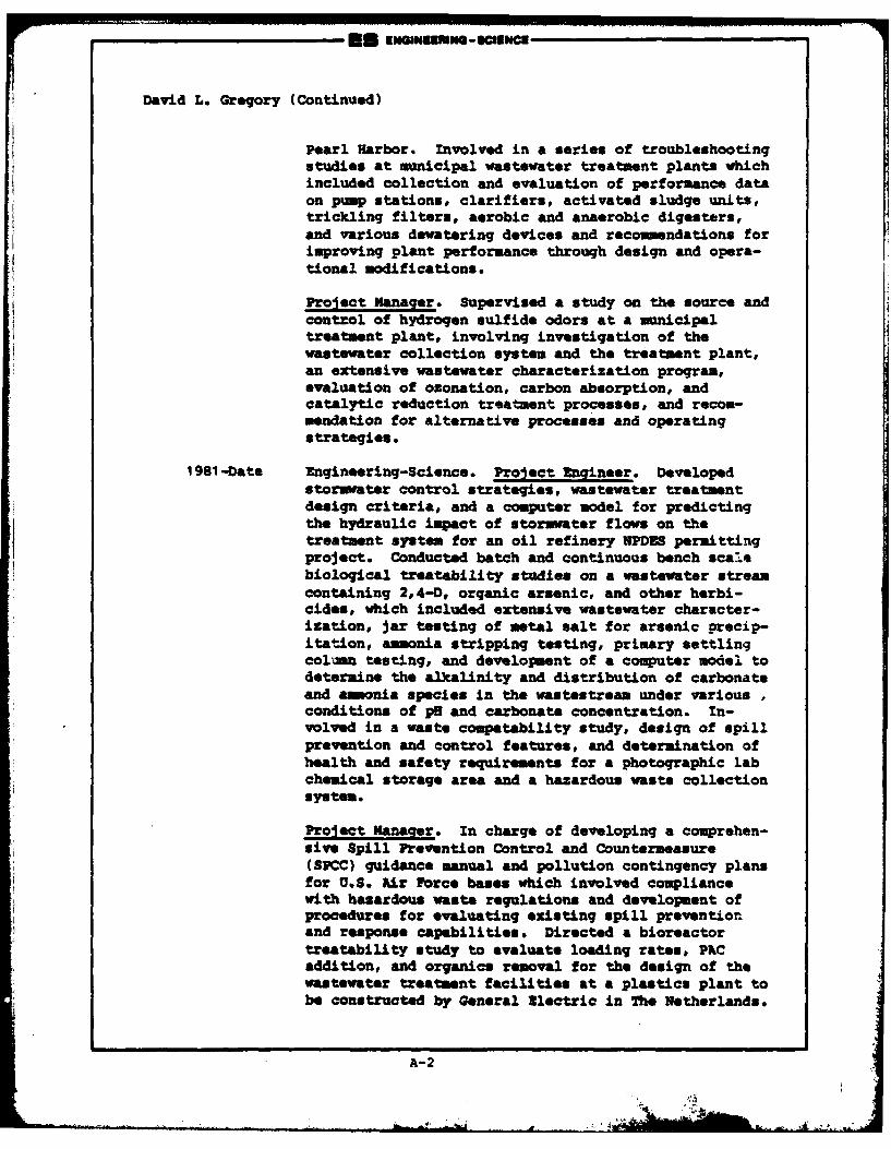
David L. Gregory (Continued)
Pearl Harbor. Involved in a series of troubleshootingstudies at municipal wastewater treatment plants whichincluded collection and evaluation of performance dataon pump stations, clarifiers, activated sludge units,trickling filters, aerobic and anaerobic digesters,and various dowatering devices and recommendations forimproving plant performance through design and opera-tional modifications.
Project Nanager. Supervised a study on the source andcontrol of hydrogen sulfide odors at a municipaltreatment plant, involving investigation of thewastewater collection system and the treatment plant,an extensive wastewater characterization program,evaluation of ozonation, carbon absorption, andcatalytic reduction treatment processes, and recom-mendation for alternative processes and operatingstrategies.
1981 -Date Engineering-Science. Project Engineer. Developedstormater control strategies, wastewater treatmentdesign criteria, and a computer model for predictingthe hydraulic impact of stormater flows on thetreatment system for an oil refinery WPDES permittingproject. Conducted batch and continuous bench scalebiological treatability studies on a wastewater streamcontaining 2,4-D, organic arsenic, and other herbi-cides, which included extensive wastewater character-ization, jar testing of metal salt for arsenic precip-itation, ammonia stripping testing, primary settlingcolumn testing, and development of a computer model todetermine the alkalinity and distribution of carbonateand ammonia species in the vastestream under variousconditions of p8 and carbonate concentration. In-volved in a waste copatability study, design of spillprevention and control features, and determination ofhealth and safety requir mnts for a photographic labchemical storage area and a hazardous waste collectionsystem.
Project Manager. In charge of developing a comprehen-sive Spill Prevention Control and Countermeasure(SPCC) guidance manual and pollution contingency plansfor U.S. Air Force bases which involved compliancewith hazardous waste regulations and development ofprocedures for evaluating existing spill preventionand response capabilities* Directed a bioreactortreatability study to evaluate loading rates, PKCaddition, and organics removal for the design of thewastewater treatment facilities at a plastics plant tobe constructed by General El.ctric in The Netherlands.
A-2
'David L. Gregory (Continued)
Pjarg. And -Presentations
w3ioloqica1 T'retaility of an Osonated Dye NAnutacture WatewMaster of ftqinewinq Special Problem Report, Clemson University,mivironmental System bqginering Department, Clemson, South Caro-lina, 1979,
A-3
Biographical Data
H. DAN HARMAN, JR.
Hydrogeologist
Education
B.S., Geology, 1970, University of Tennessee, Knoxville, TN
Professional Affiliations
Registered Professional Geologist (Georgia NO.569)National Water Well Association (Certified Water Well DrillerNo. 2664)Georgia Ground-Water Association
Experience Record
1975-1977 Northwest Florida Water Management District, Havana,Florida. Hydrogeologist. Responsible for boreholegeophysical logger operation and log interpretation.Also reviewed permit applications for new water wells.
1977-1978 Dixie Well Boring Company, Inc., LaGrange, Georgia.Hydroqeologist/Well Driller. Responsible for boreholegeophysical logger operation and log interpretation.Also conducted earth resistivity surveys in Georgia andAlabama Piedmont Provinces for locations of water-bearing fractures. Additional responsibilities includeddrilling with mud and air rotary drilling rigs as wellas bucket auger rigs.
1978-1980 Law Engineering Testing Company, Inc., Marietta,Georgia. Hydrogeologist. Responsible for ground-waterresource evaluations and hydroeological fieldoperations for government and industrial clients. Amajor responsibility was as the Mississippi FieldHydrologist during the installation of both fresh andsaline water wells for a regional aquifer evaluationrelated to the possible storage of high level radio-active waste in the Gulf Coast Salt Domes.
1980-1982 Ecology and Environment, Inc., Decatur, Georgia.ydrogeoloist. Responsible for project management of
hydrogeoiLogical and geophysical investigations atuncontrolled hazardous waste sites. Also preparedEmergency Action Plans and Remedial Approach Plans for
U.S. Environmental Protection Agency. Additional
6/83
A-4 i
H. Dan Harman, Jr. (Continued)
responsibilities included use of the MITRE hazardousranking system to rank sites on the National SuperfundList.
1982-1983 NUS Corporation, Tucker, Georgia. Rydrogeoloqist.Responsible for project management of hydrogeologicaland geophysical investigations at uncontrolled hazardouswaste sites.
1983-Date Engineering-Science, Inc., Atlanta, Georgia.Hydrogeologist. Responsible for hydrogeologicalevaluations during Phase I Installation RestorationProgram projects for the Department of Defense.
Publications and Presentations
"Geophysical Well Logging: An Aid in Georgia Ground-Water Projects,"1977, coauthor: D. Watson, The Georgia Operator, Georgia Water andPollution Control Association.
"Use of Surface Geophysical Methods Prior to Monitor Well Drilling,*1981. Presented to Fifth Southeastern Ground-Water Conference,Americus, Georgia.
"Cost-Effective Preliminary Leachate Monitoring at an UncontrolledHazardous Waste Site," 1982, coauthor: S. Hitchcock. Presented to ThirdNational Conference on Management of Uncontrolled Hazardous Waste Sites,Washington, D.C.
"Application of Geophysical Techniques as a Site Screening Procedure atHazardous Waste Sites," 1983, coauthor: S. Hitchcock. Proceedings ofthe Third National Symposion and Exposition on Aquifer Restoration andGround-Water Monitoring, Columbus, Ohio.
A-5 .
..... ... 4
#67Biographical Data
ROBERT J. REINER
Chemical Engineer
Education
B.S. in Chemical Engineering, 1979, University of Notre DameB.A. in Art, 1979, University of Notre DameM.S. in Chemical Engineering, 1980, University of Notre Dame
Honors
Amoco Company Fellowship for Graduate Studies in ChemicalEngineering, University of Notre Dame (1979-1980)
Professional Affiliations
American Institute of Chemical Engineers
Experience Record
1978-1979 PEDCo Environmental, Cincinnati. Engineer's Assistant.Responsible for compilation of data base report review-ing solid waste disposal in the nonferrous smeltingindustry. Participated in So2 scrubber emissions test-ing program, Columbus, Ohio. Worked on team establish-ing a computerized reference file on the overall smelt-ing industry. Performed technical editing and reportreview.
1979-1980 Camargo Associates, Ltd., Cincinnati. Design Engineerand Draftsman. Responsible for RVAC design on numerousprojects. Designed fire protection system for an in-dustrial plastics press. Designer on various generalplumbing jobs. Prepared EPA air pollution permit ap-plications.
1980-Date Engineering-Science. Chemical Engineer. Responsiblefor the preparation of environmental reports and permitdocuments as well as providing general environmentalassistance to clients to assure compliance with stateand federal regulations.
3/83
A-6
r-
ES mminwmscinN
Robert J. Reimer (Continued)
1980-Date Developed cost estimates for several hazardous wastemanagement facility closures. Prepared several InterimStatus Standards Manuals, including Manifest Plans,Waste Analysis Plans, Closure Plans and Contingency/Emergency Plans. Provided technical assistance in thedesign of a one-million gallon per year fuel alcoholproduction facility.
Provided assistance for a water reuse/reduction plan ata major petroleum refinery. Conducted an extensivereview of emerging energy technologies for the Depart-ment of Energy. Participated in several InstallationRestoration Proqrams for the U. S. Air Force. Assistedin the design of a contaminated ground water air strip-ping column based on a lab model to be developed. Pre-pared several delisting petitions for the removal ofindustrial wastestreams from IA's hazardous waste list.Assisted in a study of waste oil reuse for the U.S. Army
A-7
APPENDIX B
LIST OF INTERVIEWEES
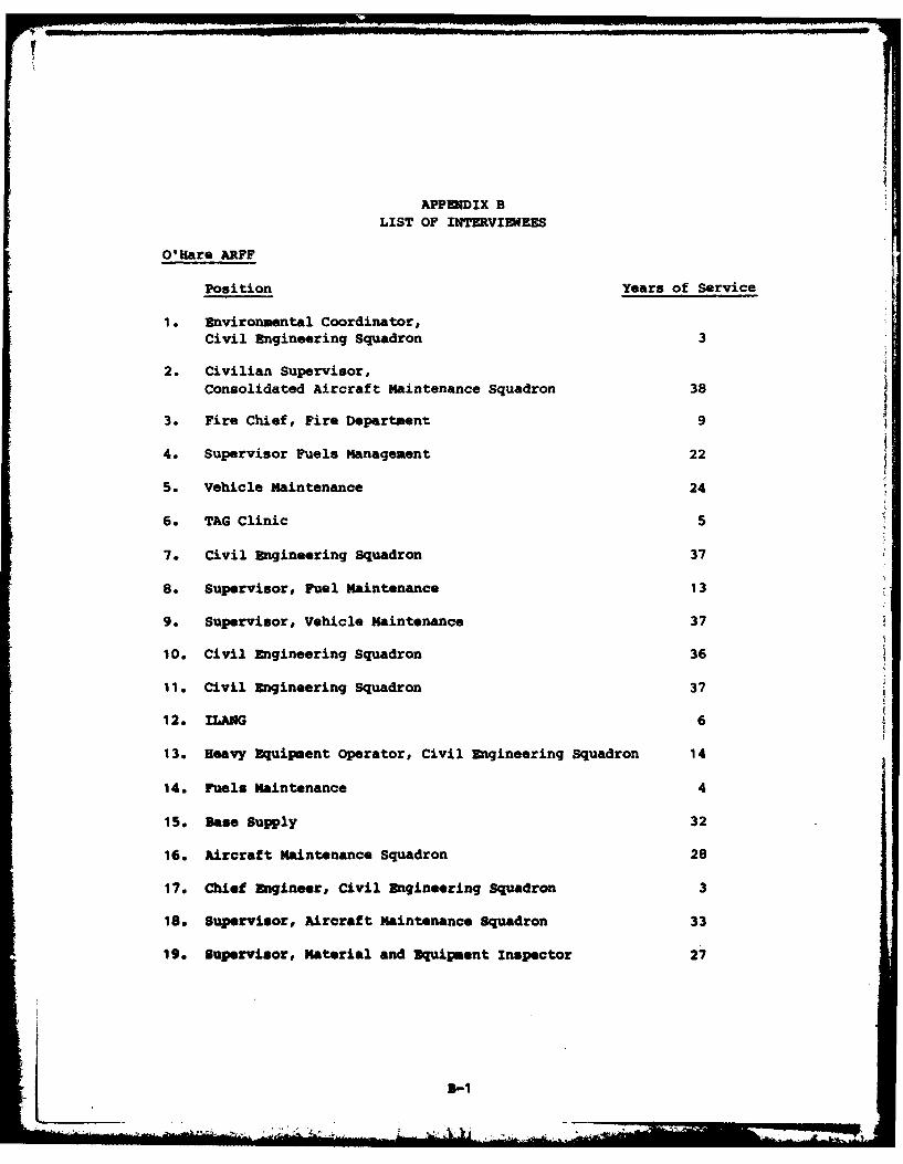
APPENDIX B
LIST OF INTERVIEWEES
O'Hare ARFF
Position Years of Service
1 . Environmental Coordinator,Civil Engineering Squadron 3
2. Civilian Supervisor,Consolidated Aircraft Maintenance Squadron 38
3. Fire Chief, Fire Department 9
4. Supervisor Fuels Management 22
5. Vehicle Maintenance 24
6. TAG Clinic 5
7. Civil Engineering Squadron 37
S. Supervisor, Fuel Maintenance 13
9. Supervisor, Vehicle Maintenance 37
10. Civil Engineering Squadron 36
11. Civil Engineering Squadron 37
12. ILANG 6
13. Heavy Equipment Operator, Civil Engineering Squadron 14
14. Fuels Maintenance 4
15. Base Supply 32
16. Aircraft Maintenance Squadron 28
17. Chief Engineer, Civil Engineering Squadron 3
18. Supervisor, Aircraft Maintenance Squadron 33
19. Supervisor, Material and Equipment Inspector 27
2-1
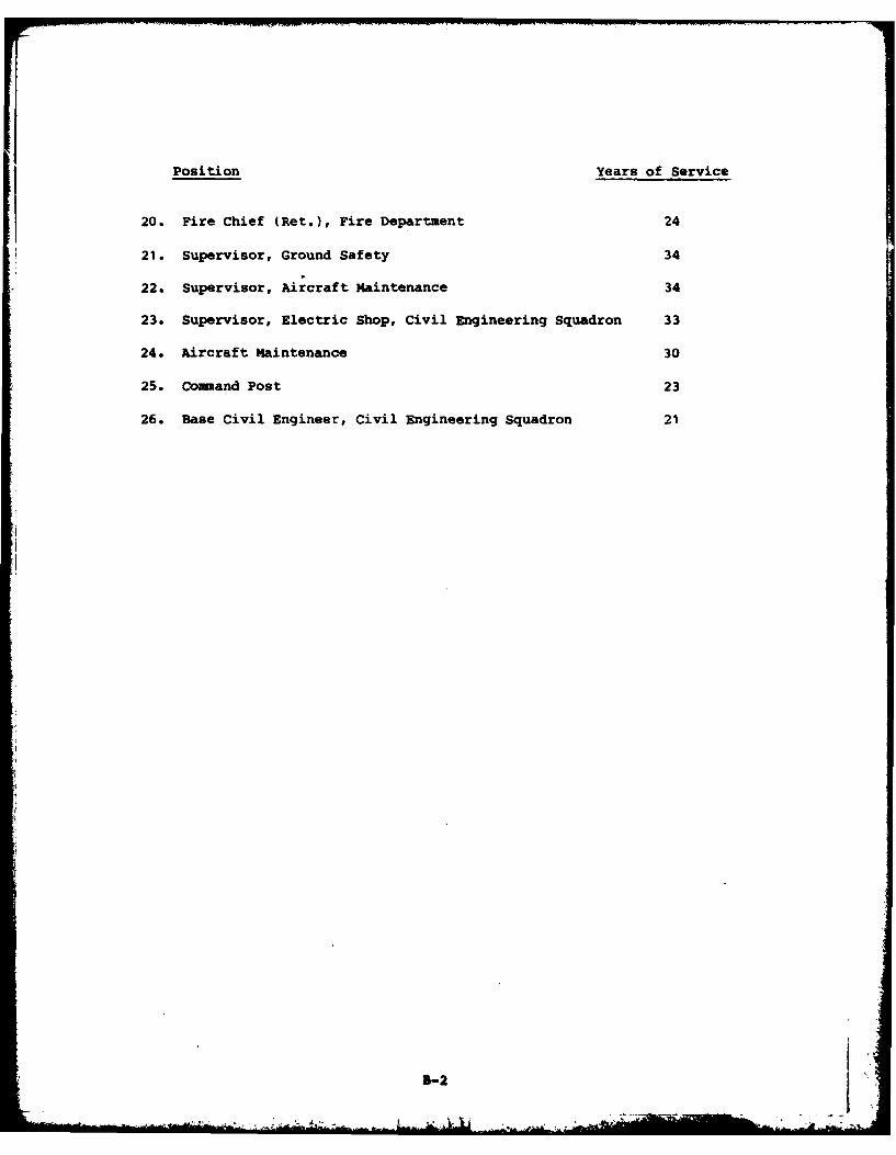
Position Years of Service
20. Fire Chief (Ret.), Fire Department 24
21. Supervisor, Ground Safety 34
22. Supervisor, Aircraft Maintenance 34
23. Supervisor, Electric Shop, Civil Engineering Squadron 33
24. Aircraft Maintenance 30
25. Command Post 23
26. Base Civil Engineer, Civil Engineering Squadron 21
B-2
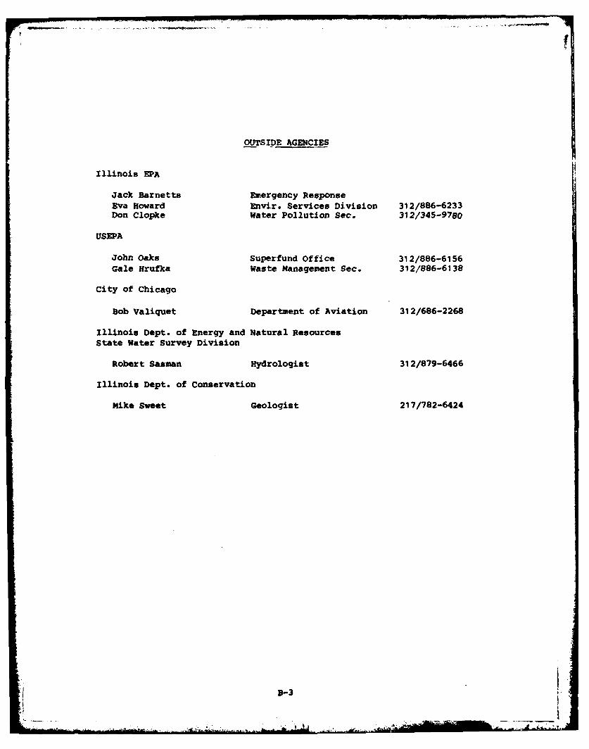
I
OUTSIDE AGENCIES
Illinois EPA
Jack Barnetts Emergency ResponseEva Howard Envir. Services Division 312/886-6233Don Clopke Water Pollution Sec. 312/345-9780
USEPA
John Oaks Superfund Office 312/886-6156Gale Hrufka Waste Management Sec. 312/886-6138
City of Chicago
Bob Valiquet Department of Aviation 31 2/686-2268
Illinois Dept. of Energy and Natural ResourcesState Water Survey Division
Robert Sasman Hydrologist 312/879-6466
Illinois Dept. of Conservation
Mike Sweet Geologist 217/782-6424
3-3
APPENDIX C
ORGANIZATIONS AND MISSIONS
4 LL
APPENDIX C
ORGANIZATIONS AND MISSIONS
PRIMARY ORGANIZATION AND MISSION
The primary mission of the 928th Tactical Air Group is to provide
individual and unit training in the C-130A, tactical airlift support for
airborne forces, equipment, supplies and aeromedical evacuation within
the theater of operations. The Group also operates and maintains the Air
Force complex at O'Hare International Airport, represents the Air Force
in the Chicago metropolitan area, and provides support to various tenant
units.
TENANT ORGANIZATIONS AND MISSIONS
The O'Hare Air Reserve Forces Facility is host to several tenant
organizations and provides facilities, services and other support to
these organizations. The following list identifies the major tenant
organizations and briefly describes their missions.
126th Air Refueling Wing, Illinois Air National Guard (IlI ANG)
The primary mission is to provide ground and aerial refueling, using
Boeing KC-135, and to maintain maximum combat readiness at minimum cost.
Other missions include fly-in ground servicing, personnel transport,
emergency air evacuation, and cargo transport. The Wing advises and
assists State authorities in the administration, logistics, traininq and
operation of the military air forces. The Wing also participates in
joint exercises and maneuvers, and provides disaster relief in domestic
emergencies.
264th Mobile Communicatons Squadron, Ill ANG
The primary mission of the Squadron is the installation, operation
and maintenance of radio relays and mobile radio relay terminals at
unprepared sites, including VHF or UHF/F? microwave and topospheric
scatter equipment. The Squadron is also responsible for the installa-
tion, operation, and maintenance of radio communications tributary
teams, including telephone, teletype and communications center functions.
C-I
217th Electronics Installation Squadron, Ill AUG
The Squadron is responsible for installation and maintenance of
ground communication-electronics equipment. The squadron consists of
four ground radio communications equipment teams, two telephone switching
teams, eight outside wire and antenna systems teams and sixteen cable
splicing teams.
36th Medical Service Evacuation Squadron
This Squadron trains to fulfill its wartime mission of providing
aeromedical staging at fixed medical facilities or other designated
locations.
USAF Liaison Office/National Scouting Organization
This office administers the USAF program of cooperation with the Boy
Scouts of America. The office acts as liaison between Air Force instal-
lations and scouts within Boy Scout Region VII (Illinois, Indiana,
Michigan, Wisconsin and eastern Iowa).
Additional Tenants
Defense Contract Administration Services Region
Defense Logistics Agency
Headquarters, Ill ANG
126th Combat Support Group, Ill ANG
126th Consolidated Aircraft Maintenance Squadron, Ill ANG
126th USAF Clinic, Ill ANG
126th Civil Engineering Flight, Ill ANG
566th USAF Band, Ill ANG
Aeronautical Systems Division, Reserve Detachment (AFLC)
Corps of Engineers Field Office
C-2
" " ' I,,- < -
APPEIDIX D
POL TANK INFORMATION
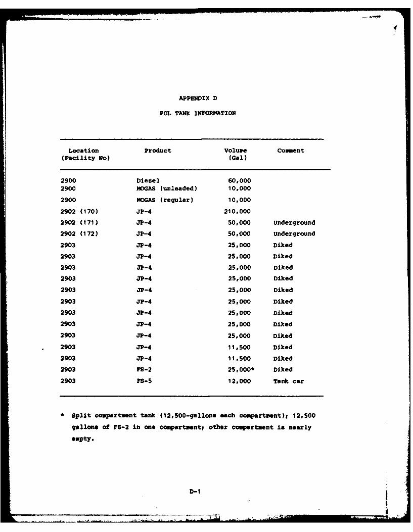
APPENDIX D
POL TANK INFORMATION
Location Product Volume Comment(Facility No) (Gal)
2900 Diesel 60,0002900 MOGAS (unleaded) 10,000
2900 MOGAS (regular) 10,000
2902 (170) JP-4 210,000
2902 (171) JP-4 50,000 Underground
2902 (172) JP-4 50,000 Underground
2903 JP-4 25,000 Diked
2903 JP-4 25,000 Diked
2903 JP-4 25,000 Diked
2903 JP-4 25,000 Diked
2903 JP-4 25,000 Diked
2903 JP-4 25,000 Diked
2903 JP-4 25,000 Diked
2903 JP-4 25,000 Diked
2903 JP-4 25,000 Diked
2903 31-4 11,500 Diked
2903 31-4 11,500 Diked
2903 FS-2 25,000* Diked
2903 FS-5 12,000 Tank car
*Split compartment tank (12,500-gallons each compartment); 12,500
gallons of Fs-2 in one compartmentl other comrtuent is nearly
empty.
D-1
APPENDIX E
MASTER LIST OF INDUSTRIAL. SHOPS
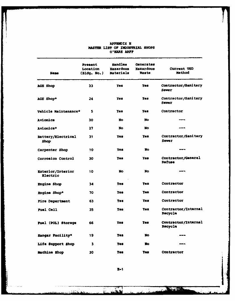
APPODIX ZMASTER LIST OF INDUSTRIAL SHOPS
0O"HARE ARF?
Present Handles GeneratesLocation Hazardous Hazardous Current TSD
Nam (Bldg. No.) Materials Waste Method
AGE Shop 33 yes yes Contractor/SanitarySever
AGE Shop* 24 yes Yes Contractor/SanitarySewer
Vehicle Maintenance* 5 Yes yes Contractor
Avionics 30 no No
Avionics* 27 No No
Battery/Electrical 31 yes yes Contractor/Sanitary
Shop Sewer
Carpenter Shop 10 yes No--
Corrosion Control 30 yes yes Contractor/GeneralRefuse
Exterior/Interior 10 No NO--
Electric
Engine Shop 34 yes yes Contractor
Engine Shop' 70 Yes yes Contractor
Fire Department 63 Yes Yes Contractor
Fuel cell 35 yes Yes Contractor/internal
Recycle
Fuel (POL) Storage 66 yes Yes Contractor/InternalRecycle
Hangar Facility' 19 yes so--
Life Support Shop 3 yes no--
machine shop 30 Yes Yes Contractor
2-1 I
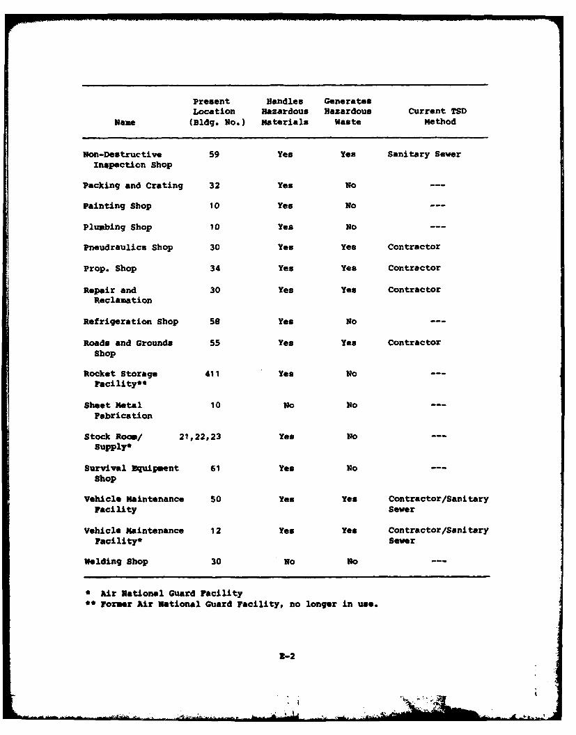
Present Handles GeneratesLocation Hazardous Hazardous Current TSD
Name (Bldg. No.) Materials Waste Method
Non-Destructive 59 Yes Yes Sanitary Sewer
Inspection Shop
Packing and Crating 32 Yes No ---
Painting Shop 10 Yes No
Plumbing Shop 10 Yes No ---
Pneudraulics Shop 30 Yes Yes Contractor
Prop. Shop 34 Yes Yes Contractor
Repair and 30 Yes Yes ContractorReclamation
Refrigeration Shop 58 Yes No ---
Roads and Grounds 55 Yes Yes Contractor
Shop
Rocket Storage 411 Yes NoFacility* *
Sheet Metal 10 No No ---
Fabrication
Stock Room/ 21,22,23 Yes No ---Supply*
Survival Equipment 61 Yes No ---Shop
Vehicle Maintenance 50 Yes Yes Contractor/Sanitary
Facility Sewer
Vehicle Maintenance 12 Yes Yes Contractor/SanitaryFacility* Sewer
Welding Shop 30 No No ---
* Air National Guard Facility" Former Air National Guard Facility, no longer in use.
2-2
- 1]
APPENDIX F
PHOTOGRAPHS
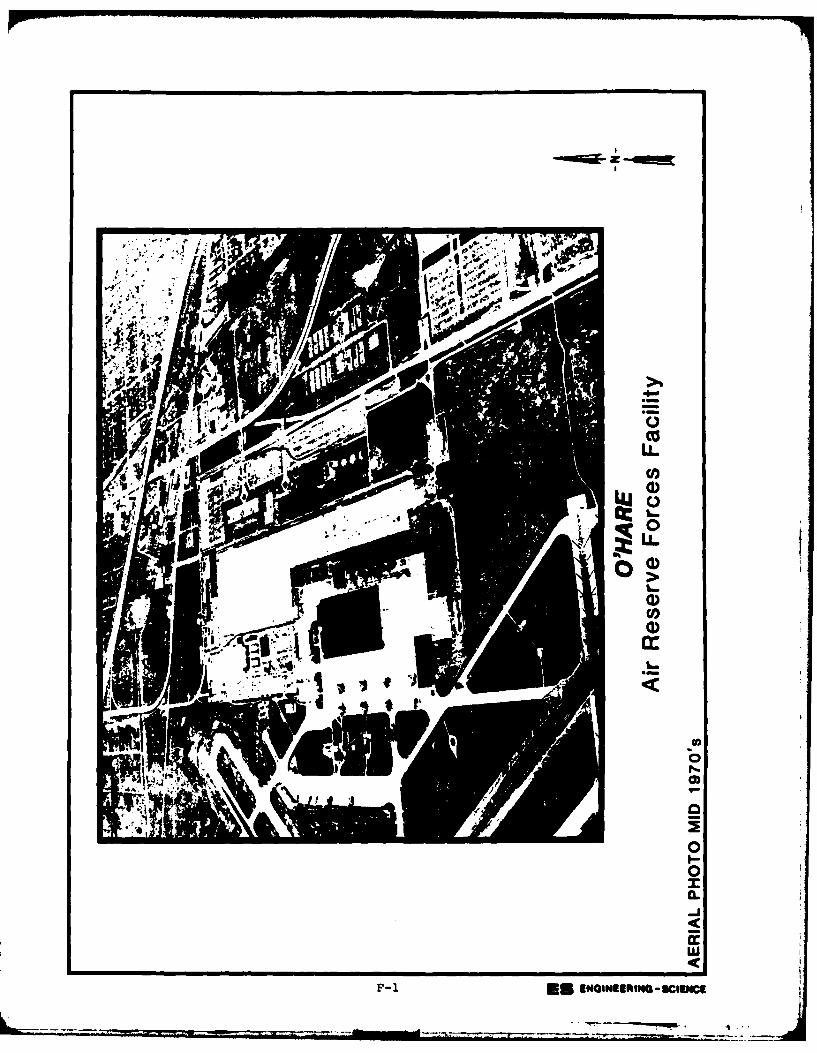
00
U-
F-1 a ENGNEERNG -sca)
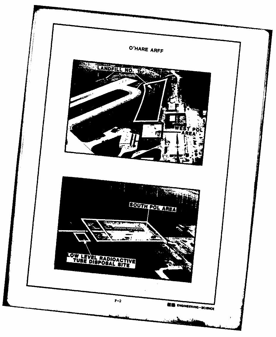
mm IULNEREg
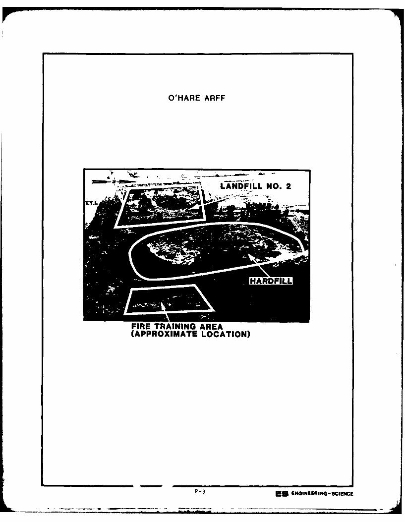
O'HARE ARFF
LANDFILL NO. 2
FIRE TRAINING AREA(APPROXIMATE LOCATION)
F-3 ES ENGINEERING -SCIENCE
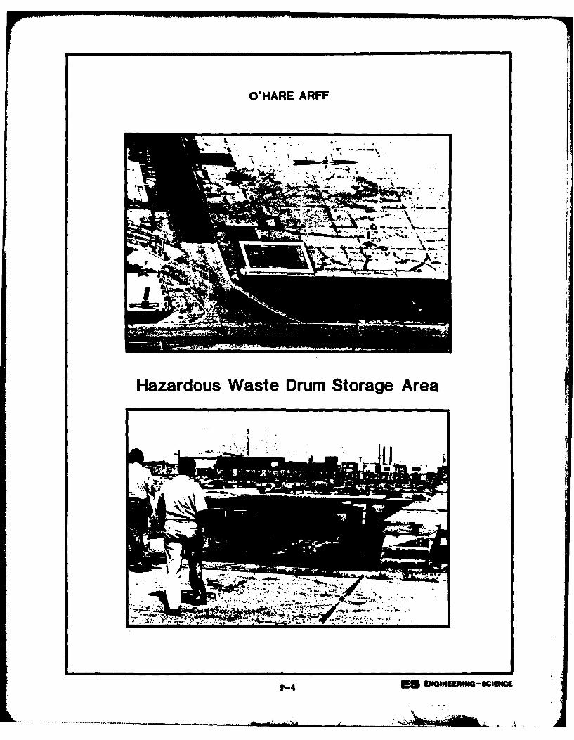
O'HARE ARFF
Hazardous Waste Drum Storage Area
4A.owuu~o-clc
APPENDIX G
USAF INSTALLATION RESTORATION PROGRAM
HAZARD ASSESSMENT RATING METHODOLOGY
i -
APPENDIX C
USAF INSTALLATION RESTORATION PROGRAM
HAZARD ASSESSMENT RATING METHODOLOGY
BACKGROUND
The Department of Defense (DOD) has established a comprehensiveprogram to identify, evaluate, and control problems associated with past
disposal practices at DOD facilities. One of the actions required under
this program is to:
ndevelop and maintain a priority listing of con-taminated installations and facilities for remedialaction based on potential hazard to public health,welfare, and environmental impacts.0 (Reference:•DEQPPM 81-5, 11 December 1981).
Accordingly, the United States Air Force (USAF) has sought to establish
a system to set priorities for taking further actions at sites basedupon information gathered during the Records Search phase of its In-
stallation Restoration Program (IRP).The first site rating model was developed in June 1981 at a meeting
with represenatives from USAF Occupational and Environmental Health
Laboratory (OEHL), Air Force Engineering and Services Center (AFESC),Engineering-Science (ES) and CH2M Hill. The basis for this model was a
system developed for EPA by JEB Associates of McLean, Virginia. The JRB
model was modified to meet Air Force needs.
After using this model for 6 months at over 20 Air Force installa-
tions, certain inadequacies became apparent. Therefore, on January 26and 27, 1982, representatives of USAF OEHL, AFESC, various major com-
mands, Engineering-Science, and CH2M Hill met to address the inade-
quacies. The result of the meeting was a new site rating model designed
to present a better picture of the hazards posed by sites at Air Forceinstallations. The new rating model described in this presentation is
referred to as the Hazard Assessment Rating Methodology.
G-1
PURPOSE
The purpose of the site rating model is to provide a relative
ranking of sites of suspected contamination from hazardous substances.
This model will assist the Air Force in setting priorities for follow-on
site investigations and confirmation work under Phase II of the IRP.
This rating system is used only after it has been determined that
(1) potential for contamination exists (hazardous wastes present in
sufficient quantity), and (2) potential for migration exists. A site
can be deleted from consideration for rating on either basis.
DESCRIPTION OF MODEL
Like the other hazardous waste site ranking models, the U.S. Air
Force's site rating model uses a scoring system to rank sites for
priority attention. However, in developing this model, the designers
incorporated some special features to meet specific DOD program needs.
The model uses data readily obtained during the Records Search
portion (Phase I) of the IRP. Scoring judgments and computations are
easily made. In assessing the hazards at a given site, the model
develops a score based on the most likely routes of contamination and
the worst hazards at the site. Sites are given low scores only if there
are clearly no hazards at the site. This approach meshes well with the
policy for evaluating and setting restrictions on excess DOD properties.
As with the previous model, this model considers four aspects ofthe hazard posed by a specific site: the possible receptors of the
contamination, the waste and its characteristics, potential pathways for
waste contaminant migration, and any efforts to contain the contami-
nants. Each of these categories contains a number of rating factors
that are used in the overall hazard rating.
The receptors category rating is calculated by scoring each factor,
multiplying by a factor weighting constant and adding the weighted
scores to obtain a total category score.
G-2- 2
The pathways category rating is based on evidence of contaminant
migration or an evaluation of the highest potential (worst case) for
contaminant migration along one of three pathways. If evidence of
contaminant migration exists, the category is given a subscore of 80 to
100 points. For indirect evidence, 80 points are assigned and for
direct evidence, 100 points are assigned. If no evidence is found, the
highest score among three possible routes is used. These routes are
surface water migration, flooding, and ground-water migration. Evalua-
tion of each route involves factors associated with the particular mi-
gration route. The three pathways are evaluated and the highest score
among all four of the potential scores is used.
The waste characteristics category is scored in three steps.
First, a point rating is assigned based on an assessment of the waste
quantity and the hazard (worst case) associated with the site. The
level of confidence in the information is also factored into the
assessment. Next, the score is multiplied by a waste persistence
factor, which acts to reduce the score if the waste is not very
persistent. Finally, the score is further modified by the physical
state of the waste. Liquid wastes receive the maximum score, while
scores for sludges and solids are reduced.
The scores for each of the three categories are then added together
and normalized to a maximum possible score of 100. Then the waste man-
agement practice category is scored. Sites at which there is no con-
tainment are not reduced in score. Scores for sites with limited con-
tainment can be reduced by 5 percent. If a site is contained and well
managed, its score can be reduced by 90 percent. The final site score
is calculated by applying the waste management practices category factor
to the sum of the scores for the other three categories.
G-3
,7
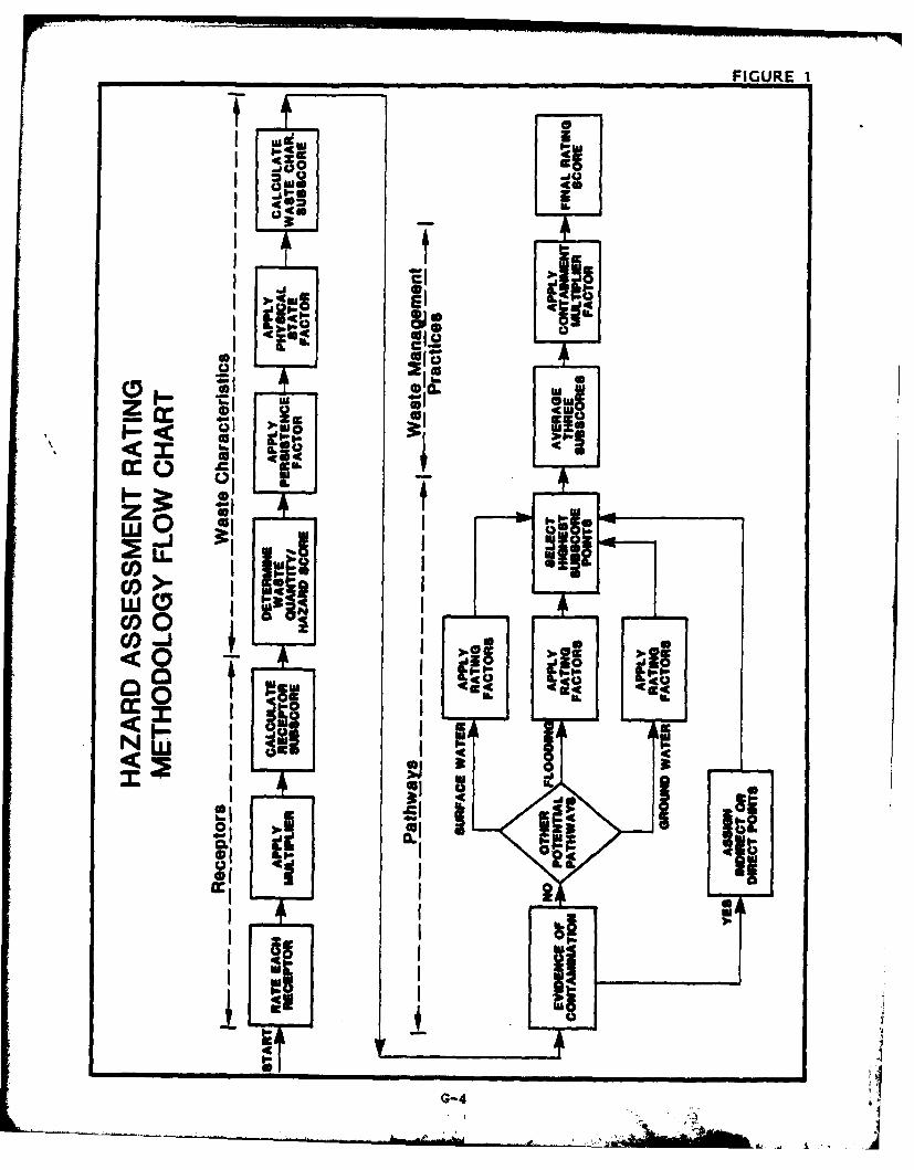
FIGURE I
ow-At-j
I C
cr 0
ziWI 0
CO I-tA
w I9
COOjc m )II I-<0 _ 1
IIca
1C1 I IA.
o 40
CLI
G-4
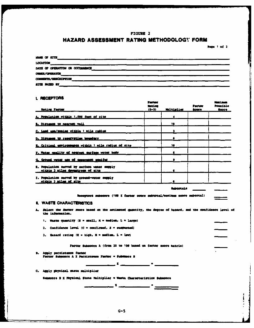
FIGUR 2
HAZARD ASSESSMENT RATING METHODOLOOV, FORMPairs o f 2
oma w m
L fhCEPTORS8
htlasFactor PassbLenatins peasto (0-3) "aftyi sowes somre
A.Imaalswthn1.000 fae @ le - 4 _____
C.L~iasaelswithin I Stue COAium 3-
7- CiticaL eim est within I mlem uadius at site 10______
P. Natm quaLity at saes~et astfass water be" __________
3. Gupalatin sora by sactat Nmus - 9 1I. PaJesU srved by gleamtm UULY
l~a~au ib~we(106 1 tustar .m.~saahasew@sr aueawa)
L WASTE CHARACTENhSTICSA. fLoeo Me fator woe, beas" an Se atiatei quatity, On degre. at bsmir, an the osfidease leveL of
the inismatift.
1. waste qoamity (8 0 Mai x a aedivin 1. 6 .ge
2. Conf idence leow" (C a csmilassi. I a maSPNPsAil
3. nasard rating (UB hgh# K aedIm.Lueawto-
taccts uborn.e A (gem 20 to Ice baede an tate Sm ase el)-
a. 4pLY Pesi stece factorFactor Sub"sse A x PegeIAaeeu Pastne a lubSsee a
C. Apply pbymia" Mato msitplier
Stabeece a I Phy"Sies tate ~Iftpus Sa Wase ractocims al*seoe
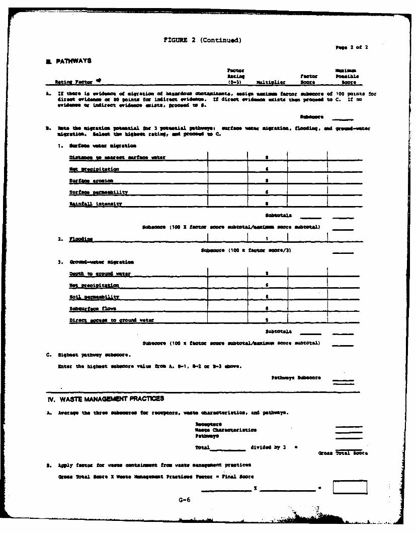
FIGURE 2 (Continued)ww. 2 ofl 2
IL PA7hWAYS
Rating ractor Postble.atli rator (0-3) mgeiouste Scoe .:ote
. 19 maore is evidence of atiratoi Of bgudou5 OOtaaiaamt, assign mim ftor bre of 100 points !a,direct evidegam cc so points ftog tdiream wodm. If direct evi e x ists than proMd to C. If noevideme cc tdirect evidemfe ialta *ocied to S.
I-gear.
S. At. te migratiom iotent al Tot 3 potential ptbueys, ianse. wer aIgation, floo ingiad Im terIlgratice. Salem the biet rati0.au n t d to C.
1. I-fae wM aIgrata
Mstaac to sergest surt ap. water_______ S ______
N* et civitatio. _____ 6 ___________
Surface iersion _r_ 8
suemif emU amity ______ 6 _____ _____
iI ot is I
1user (100 1 factor eae "Mtoa.n mre MbtotaL.) -
2. flodins - I t ISubsume (100 x factor scoe/Il
3. 0 to-runtd aert.
S96-M eiiat . .
Subrf m flow .,_ _ _ __l.tneet~r,_ _ _I _
Direct access to @rowod "ater____________ ____
Subtotals
Subacore (00: factor ams ab/t ou score subtotal)
C. floghat- pathway OWNMbc.
Set the highest sabscore value fr A. 3-1, 1-2 a, -3 ove.
Pathways Sukecore
IV. WASTE MANAGEMENT PRACTICES
A. Average the three abemes tor eclor.. vaste characteristics. sd patway.
anceptoteNam CCartbistics-
Pathwan. -
Tctal_ _ dividd by 3
3. Awy factor fag Wase conta~uent from Waste mamagement practices
Groa Total Saeoe I waste MNanernmt Practices Pe r Ifinal Sore
G-6
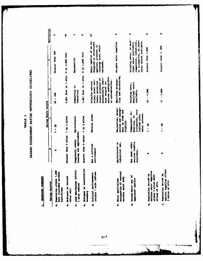
a to
a a ,aa
0
~c
1 4, 20
3 ~~ 41a.o .- Va.-
4~04
0 - I 4-4 -Iw 1 .4
at diiS ~ 9 9O0
4,4 41 4 4G-7
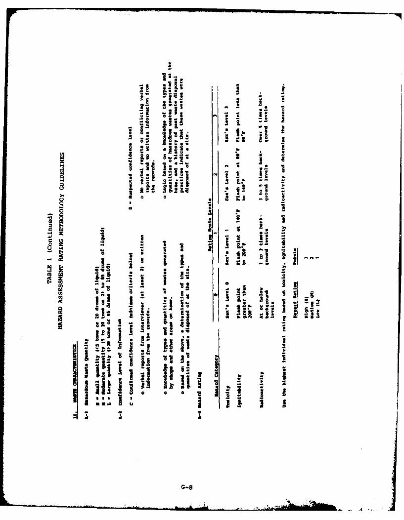
"d Cd L -
aa 06 A~
r ......
al do
ad 21,g 1.
*SMS -
* "£." I, 6
, I ,*
1 0t. Ice,
04
IVI
4456 j.1
:1: 1
0! +, 9a++ + d10
ad- Ii U i |
44d a. caA40 + -INA to
t Iad
0 04
aa
G-8
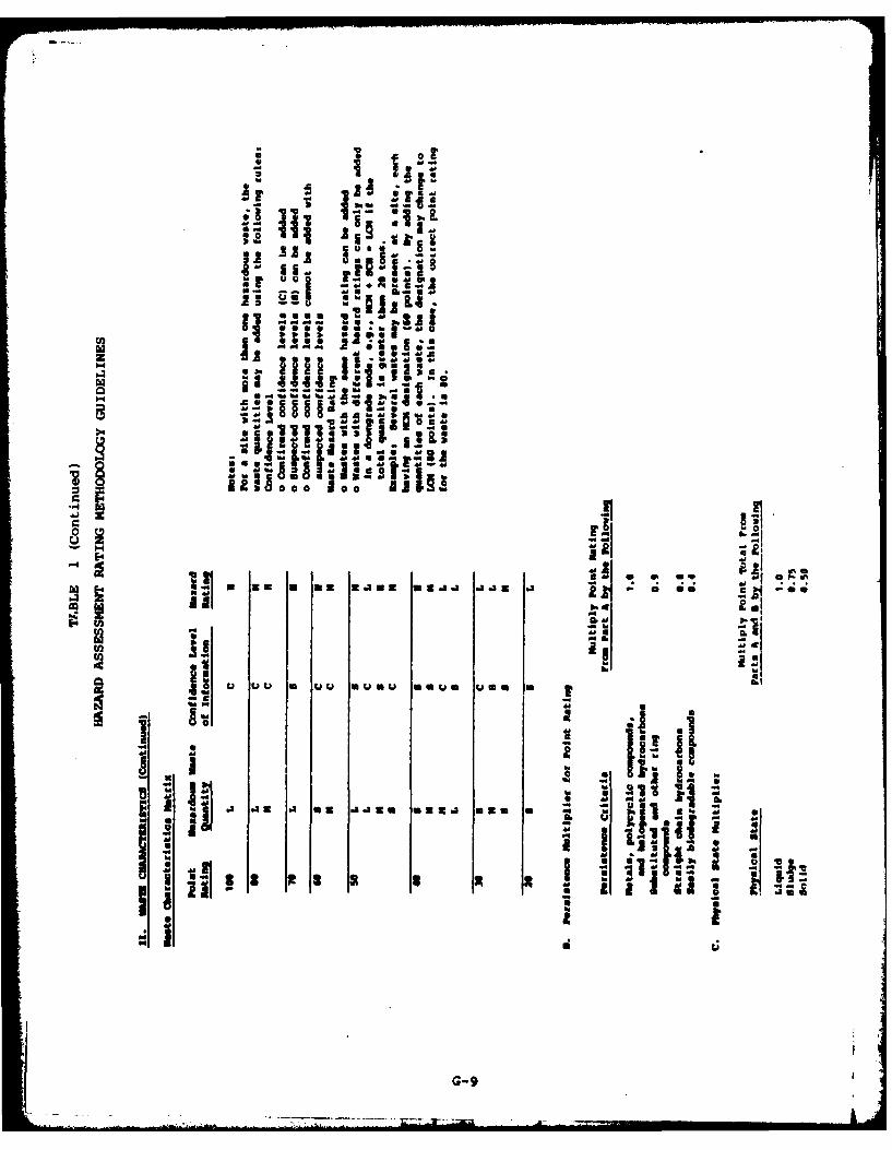
o f 2!eAseU em ad
3s~Ar zA
~ ~ U .~JA rIM --
~ rUadI~i8* -- £ !~-. U adS ~-- u
U... '5
0@s* S
* ad3 ~M~3M
- guu~ seep...Ca2 44443
-- --- S U5.6a.. '5IMh.4
a. a~adb ~ad*
4. ~
.IIJ11I1~.;~!.Iy -U
_ *~I1'ad - ad
aa.A0 0 0 1. ~ 11 .a i~I.iii urn - * **
* 2.1
C ji~ Mg
jo u uu m uu *umu mourn use m 1Ma
t~IIs.ad ad L2.~
ha flad - -z .~ ha
ha S 00 b3 -* ad 4. a 3 0.
- --p.: 0. U ad IS I
.3 dUaloU ~iim *U~d SEam ~ jI1~j~1;.~- ~ I
ad
Ii~I1 ,3 I ~1: ;.~* ii~* 2ad
G-9
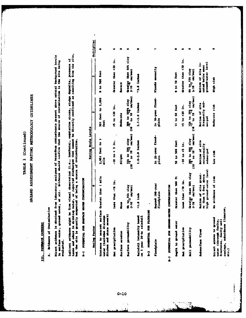
*a 1
4- 1d If 0 0
40-
pm if, j~d.44
40 q
Cal a ma1-4 In V
NO 14 + 0 @ U
0 20 2 MS2
MIsM
2 40
a 0a ~ -
S~o 30 b.IM E** 0
00 4
41.
a. 96 I 4 t
4 Mw s 4 4(
G-10
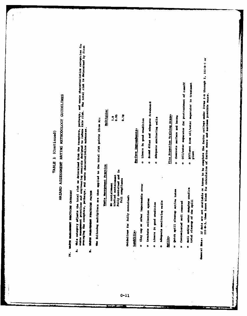
OM
h.* -gsa'
06.
a a
ma' -U. -is .6
.6 .6a'.g.eM I
2
SSM 6
2 .6
a' 55I" 0I A .6
'-4 * 1 a'.6'
'Iia; : :- ~1I! SE
a' MU .1 a'
* jyiRI! i ~m.Z 5;4.J
a .6 - g02 * ~qM
56.6 16 -*~' 3ME4 -: -~ I ~ SM
II" ~ aa' A.
S 0 0 0 b 0 0 0- S
Si - .6
N ~ M~3* Ei. 2
1z1 II~ 5 .6
~ ~ - - 3 1II~ I a~ aI ~ -'A
E 0 ~3.60a 3~. .
g ~* a I3
lull I I *~~ .6
4 a I
iG-11
I
APPENDIX H
HAZARD ASSESSMENT RATING FORMS
I , "
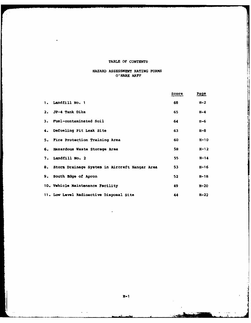
TABLE OF CONTENTS-
HAZARD ASSESSMENT RATING FORMSO'HARE ARFF
Score Page
1. Landfill No. 1 68 H-2
2. JP-4 Tank Dike 65 H-4
3. Fuel-contaminated Soil 64 H-6
4. Defueling Pit Leak Site 63 H-8
5. Fire Protection Training Area 60 H-10
6. Hazardous Waste Storage Area 58 H-12
7. Landfill No. 2 55 H-14
8. Storm Drainage System in Aircraft Hangar Area 53 H-16
9. South Edge of Apron 52 H-18
10. Vehicle Maintenance Facility 49 H-20
11. Low Level Radioactive Disposal Site 44 H-22
H-i
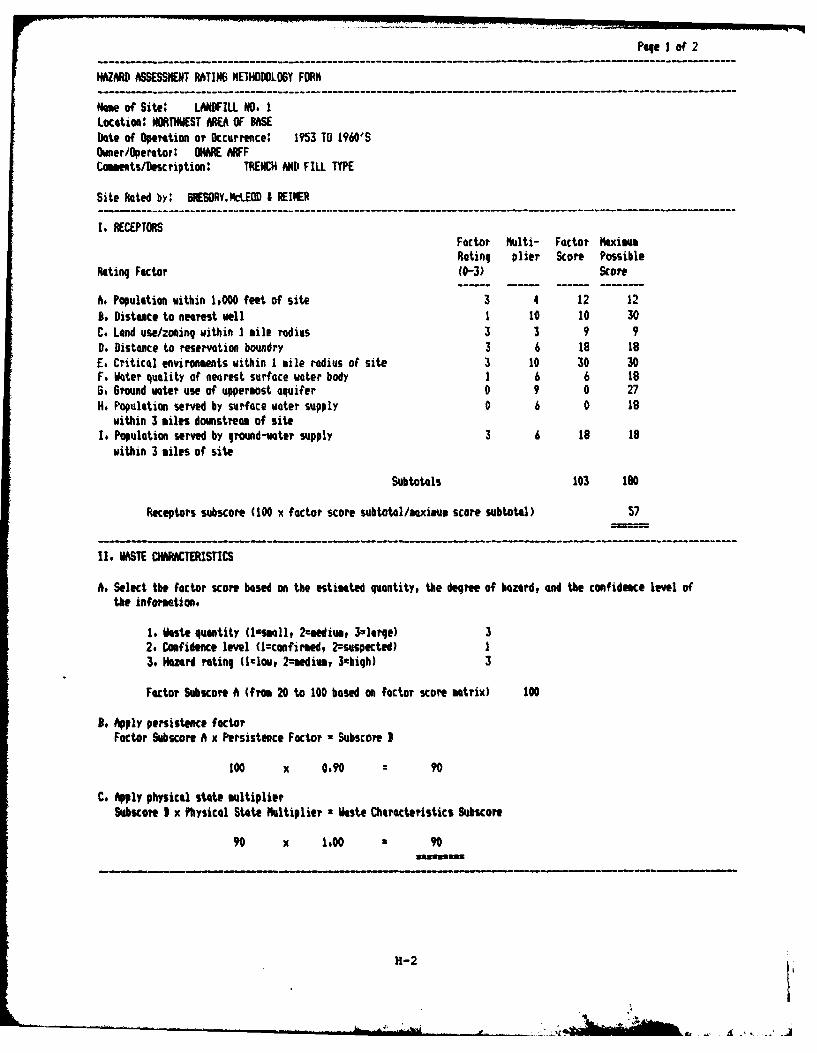
Page I of 2
HAZARD ASSESSMENT RATIN6 METHODLOGY FORM
Name of Site: LANDFILL NO. ILocaton: NORTHWEST NEA OF BASEDate of Operation or Occurrence: 1953 TO 1960'SOwner/Operator: O(ARE AFFCOments/Description: TRENCH AND FILL TYPE
Site Rated by: 6REGORY.NLEOD t REINER
I. RECEPTORSFactor Multi- Factor MaximumRating plier Score Possible
Rating Factor (0-3) Score
A. Population within 1,000 feet of site 3 4 12 12B, Distance to nearest well 1 10 10 30C. Land use/zoning within I mile radius 3 3 9 9D. Distance to reservation boundry 3 6 18 18E. Critical environments within I tile radius of site 3 10 30 30F. Water quality of nearest surface water body 1 6 6 186, Ground water use of uppermost aquifer 0 9 0 27H. Population served by surface water supply 0 6 0 18
within 3 miles downstream of siteIt Population served by ground-water supply 3 6 18 18
within 3 miles of site
Subtotals 103 180
Receptors subscore (100 x factor score subtotal/oaximu score subtotal) 57
II. WASTE CHMPATERISTICS
As. Select the factor score based on the estimated quantity, the degree of hazard, and the confideace level ofthe informetion.
1, Waste quantity (l-small, 2eediv, 3=lIre) 32. Confidence level (lconfirmed, 2=suspected) 13. HNazard rating (l1lw, 2-sediu, 3ahiqh) 3
Factor Subscore A (from 20 to 100 based on factor score matrix) 100
, Apply persistence factorFactor Subscore A x Persistence Factor = Subscore I
100 x 0.90 : 90
C. Apply physical state multiplierSubscoe I x Physical State Multiplier 2 Waste Characteristics Subscore
90 x 1.00 90
H-2
°rI
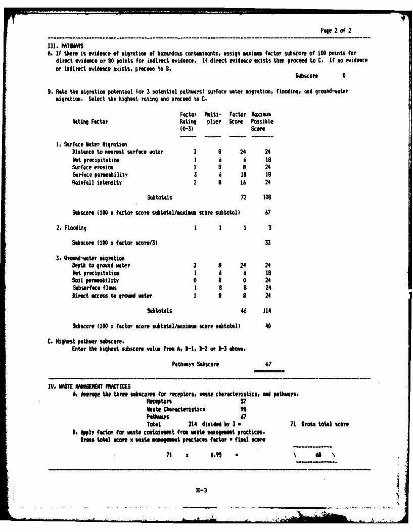
Page 2 of 2
III. PATHWAYSA. If there is evidence of migration of hazardous contaminants, assign maximm factor subscore of 100 points for
direct evidence or 80 points for indirect evidence, If direct evidence exists then proceed to C. If no evidenceor indirect evidence exists, proceed to B.
Subscore 0
9. Rate the migration potential for 3 potential pothways' surface water migration, flooding, and ground-vatermigration. Select the highest rating and proceed to C.
Factor ulti- Factor MaximaRating Factor Rating plier Score Possible
(0-3) Score
1. Surface Voter igrationDistance to nearest surface woter 3 8 24 24Net precipitation 1 6 6 18Surface erosion 1 8 8 24Surface permeability 3 6 18 18
infall intensity 2 8 16 24
Subtotals 72 108
Subscore (100 x factor score subtotal/mximm score subtotal) 67
2. Flooding 1 1 1 3
Subscore (100 x factor score/3) 33
3. Ground-vater migrationDepth to ground water 3 9 24 24Net precipitation 1 6 6 19Soil permeability 0 8 0 24Subsurface flows 1 8 8 24Direct access to grond voter 1 9 8 24
Subtotals 46 114
SUbscore (100 x factor score subtotl/aximm score subtotal) 40
C. Highest pathway subscore.Enter the highest subscore value from A, 3-1, 3-2 or B-3 above.
PathWays SUcore 67
IV, WSTE WMAENT PRCICESA. Averge the three subcores for receptors, wasto cbhrcteristics, and pethwayst
Receptors 57Vaste OaracteristicsPathways 67Total 214 divided by 3 u 71 Gross total score
3. APIY factor for Waste containment from waste Maagm t practices.GrMs total score x Vaste mnm t practices factor final scoe
71 x 0.95 a 68
H-3
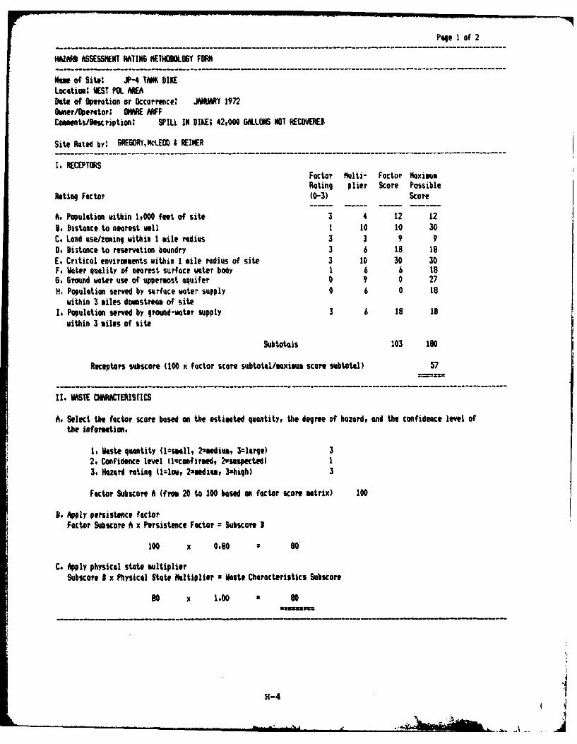
Pqe I of 2
HAZARD ASSESSMENT RATIN6 HEIHODOLOSY FORM
Nme of Site: JP-4 TANK DIKELocation: WEST POL AREADate of Oieration or Occurrence: JNUARY 1972OIer/Ipertor: OWN ARFFCommntsDescription: SPILL IN DIKE; 42,000 6&LLONS NOT RECOVERED
Site Rated by: 6RE6ORY.NcLEOD I REINER
I, RECEPTORSFactor Multi- Factor MaximusRating plier Scare Possible
Rating Factor (0-3) Score
A. Populetion within 1,000 feet of site 3 4 12 123. Distance to nearest well I 1o 10 30C. Lend use/zoning within 1 mile radius 3 3 9 90. Distance to reservation boundry 3 6 18 18E. Critical envirmments within I mile radius of site 3 10 30 30F, Water quality of nearest surface water body 1 6 6 186. 6round water use of uppermost aquifer 0 9 0 27H. Population served by surface water supply 0 6 0 18
within 3 miles domstream of siteI. Population served by pound-water supply 3 6 18 18
within 3 miles of site
Subtotals 103 180
Receptors subscore (100 x factor score subtotl/maximum score subtotal) 57
II. WASTE CmARACEISriCS
A. Select the factor score based on the estimated quantity, the degree of hazard, and the confidence level ofthe information.
1. Waste quantity (U=smll, 2=medium, 3=large) 32, Confidence level (=cmnfirmed, 2usvspected) 13. Hazard rating (1:1ow, 2-medium, 3-high) 3
Factor Subscore A (from 20 to 100 based on factor score mtrix) 100
a. Apply persistence factorFactor Subscore A x Persistence Factor = Subscore I
100 x 0.80 = 80'
C. Apply physical state multiplierSubscore B x Physical State Multiplier • Waste Characteristics Subscore
90 x 1.00 80
H-4
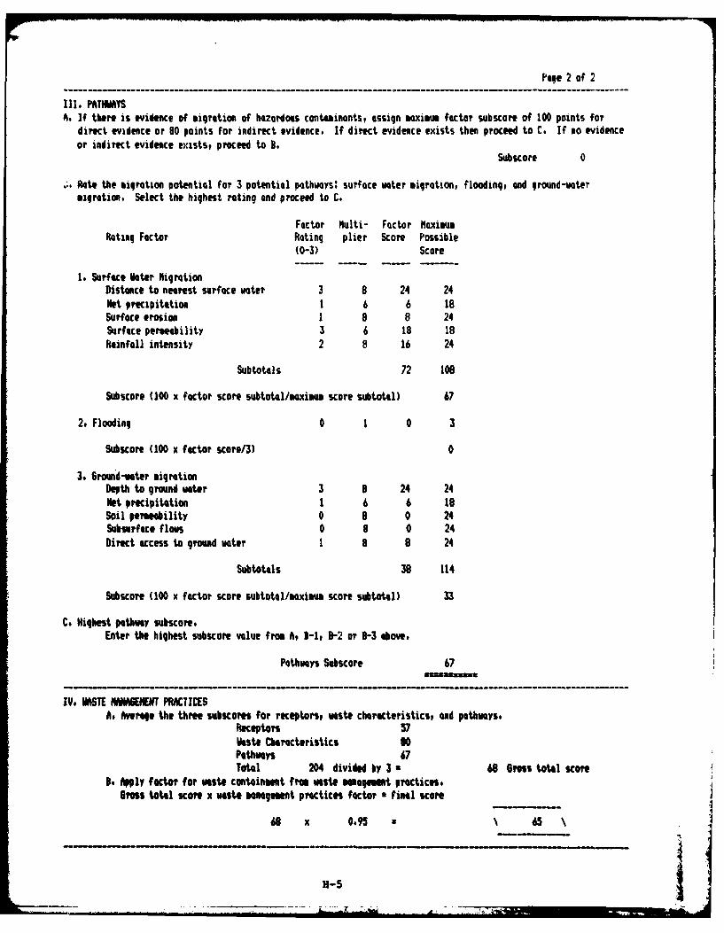
Page 2 of 2
IlI. PATHWAYSA. If there is evidence of migration of hazardous contaminants, assign maximum factor subscore of 100 points for
direct evidence or 80 points for indirect evidence, If direct evidence exists then proceed to C. If no evidenceor indirect evidence exists, proceed to 1.
Subscore 0
R:. Rate the migration potential for 3 potential pathways: surface wter migration, flooding, end ground-watermigration. Select the highest rating and proceed to C.
Factor Multi- Factor NaximusRating Factor Rating plier Score Possible
(0-3) Score
1. Surface Meter higrationDistance to nearest surfece water 3 8 24 24Net precipitation 1 6 6 18Surface erosion 1 a 8 24Surface permeability 3 6 18 18Rainfall intensity 2 8 16 24
Subtotals 72 1O
Subscore (100 x factor score subtotal/aximm score subtotal) 67
2, Flooding 0 1 0 3
Subscore (100 x factor score/3) 0
3. 6round-water migrationDepth to ground water 3 9 24 24Net precipitation 1 6 6 18Soil permeability 0 9 0 24Subsurface flows 0 8 0 24Direct access to ground water 1 8 8 24
Subtotals 38 114
Subscore (100 x factor score subtotal/maximm score subtotal) 33
C. Highest pathway subscore.Enter the highest subscore value from A, 3-1, B-2 or B-3 above.
Pathways Subscore 67
IV, ViSTE NAINGEMT PRACTICESA. Average the three subscores for receptors, waste chrcteristics, and pathways.
Receptors 57kste Characteristics 80Pathways 67Total 204 divided by 3 u 68 Gross total score
N, Apply factor for waste containment f rm waste managemut practices.Gross total score x waste maagement practices factor final score
68 x 0.95 N 65
H-S
.. . . . . . .-- " . . . . .. . . ": + -+ J ,,,+ :* ' ,LeIA '
• .1
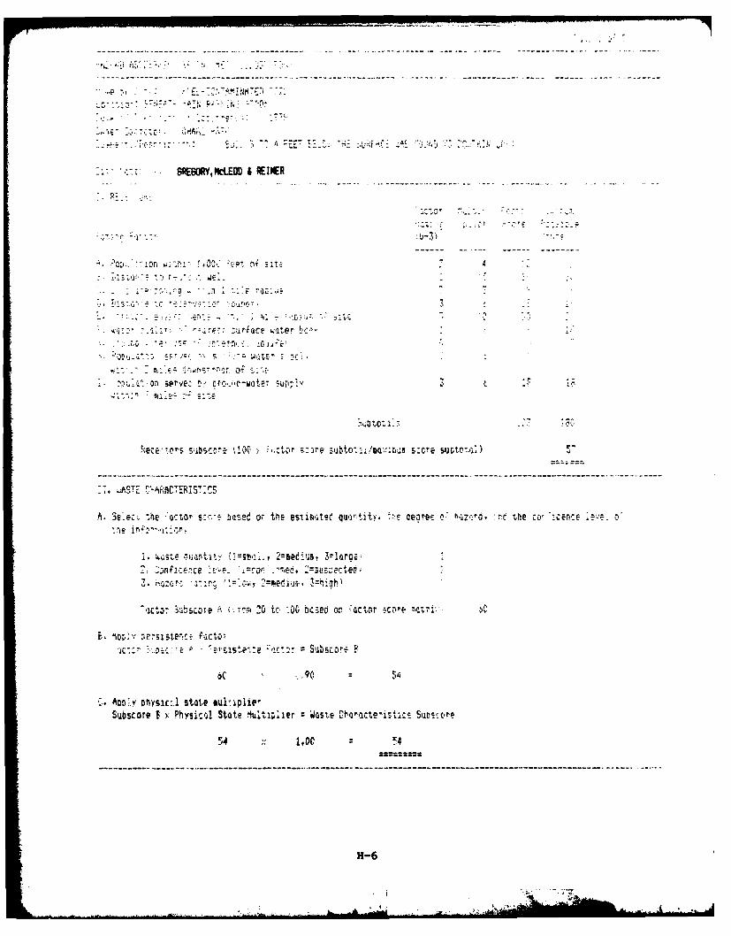
--- . - -. --. -- -
BRE.. RY, WcLEM & REINER
4 ooi.- h '' ~ fT st
-Z C 0
:.I - : ac" - t r p" -
:f L' A I i
-k sp3 erve c rc"Cw te (-1 U
",CE:.or SSCo -e .r , "5C z0 to, :-oto- .rtl; score,'Y
A. Sc te at: ;sir based o er te actIrwt~e qurtitv, :t eare: 0. hc;71zd- :rt tle ccSr.,
N * ..iuatit- :. 2=eed~ii, 3-lora.
c -b" -e" 20 tC -00 bcsed or :actr scjre
n.3% 00V ;jisWt- facto.;
6C -. 90 5
A. AD&Y OhysicA state Sui-1plip
Subscore f6>: Physical State lulti;lier --Waste ChWacteistacs Suococtr
H-6
Am-
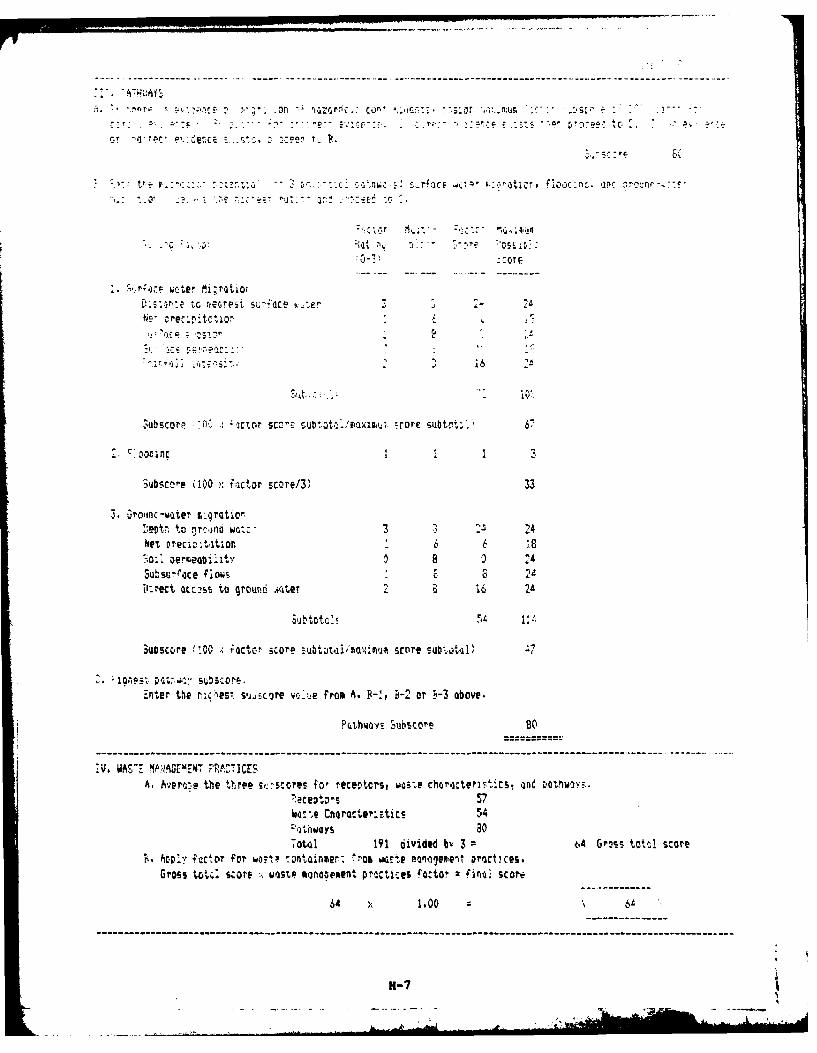
C- :yr ri::c P, C
*~ 3'-~--x- -----
Nrcrcpic i o 6c" cr ubCl-j
3uibscere (100 x factor score/3' 33
3, Oroinc-water 1:cflltior
:-evtW to nrcsno watt'3 2Net preciatior 6 18
Subsurtoce flows 8 -2 411I-rect QcC,2s5 to qrouin.' i.cter 2 8 16 2t4
Suascore 1100 . ;actor ;core sub t~taiaxrnum score subtotafil):
Ent.er the nu')est sujicore vreu-e from A ,-2or 'e-3 above.
Pcthwovs Siibscore 80
:N. WAVE 9VN.AGE MEW7 PRC TICESA. Averone the three sigiscorns for receptcrs, woste@ choroteristics, -and Dotnlwqvs.
Kece~tors 5740:;,e Cnarcte':stics 54
i.thIwoys 30Toteal 191 divided by 3 =t-4 Gross tattl score
f. Al> factor for wa:tC tontainmer: >o7at wGE4e oniagevient arocicers.Gross toc score xwaste monoqement p'scItices factor finoj- score-
64 x 1.00 -4
11-7
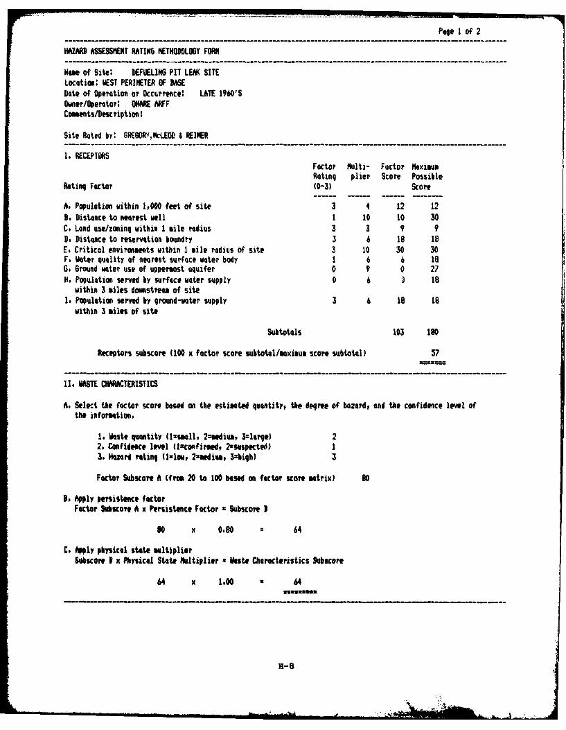
Page I of 2
HAZARD ASSESSIENT RATIN6 METHODOLOGY FORM
Name of Site: DEFUELIN6 PIT LEAK SITELocation: WEST PERIMETER OF SASEDate of Operation or Occurrence: LATE 1960'SOwner/Operator' OA ARFFComents/lescription:
Site Rated by: GR6ORV,N-LEOD & REINER
1. RECEPISFactor Multi- Factor MaximumRating plier Score Possible
Rating Factor (0-3) Scope
A. Population within 1,000 feet of site 3 4 12 12B. Distance to nearest well 1 10 10 30C. Land use/zoning within 1 mile radius 3 3 9 9D. Distance to reservation boundry 3 6 18 18E. Critical environments within 1 mile radius of site 3 10 30 30F, Water quality of nearest surface water body 1 6 6 186. Ground water use of uppermost aquifer 0 9 0 27H. Population served by surface water supply 0 6 18
within 3 miles dmmstream of siteI. Population served by ground-water supply 3 6 18 IS
within 3 miles of site
Subtotals 103 190
Receptors subscore (100 x factor score subtotl/txiu score subtotal) 57
II, WASTE CHAACTERISTICS
A. Select the factor score based on the estimated quantity, the degree of hazard, and the confidence level ofthe information.
1, Waste quantity (lzsmall, 2umedium, 3-large) 22. Confidence level (lconfirmed, 2-suspected) I3. Hzard rating (il-low, 2amediu, 3=high) 3
Factor Subscore A (from 20 to 100 based on factor score matrix) 80
B. Apply persistence factorFactor Subscore A x Persistence Factor z Subscore B
80 x 0.80 = 64
C, Apply physical state multiplierSakscore I x Physical State Multiplier a Vste Characteristics Subscore
64 x 1,00 • 64
H-B
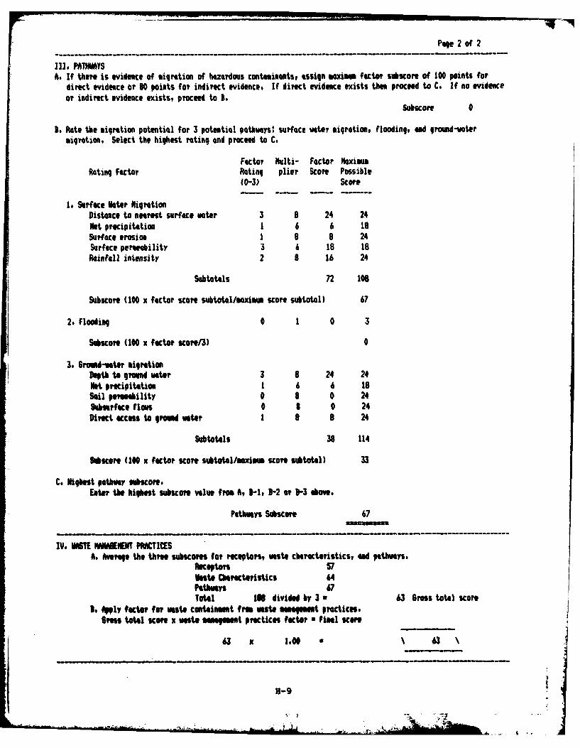
Page 2 of 2
Ill, PATI"YSAs If there is evidence of migration of hazardus contaminants, assign mxim factor subscore of 100 points for
direct evidence or 80 points for indirect evidence# If direct evidence exists than proceed to C. If no evidenceor indirect evidence exists, proceed to B.
Subscore 0
3. late the migration potential for 3 potential pathways: surface water migration, flooding, and ground-votermigration. Select the highest rating and proceed to C,
Factor Multi- Factor MaximumRating Factor Rating plier Scort Possible
(0-3) Score
1. Surface ter NigrationDistance to nearest surface voter 3 B 24 24Net precipitation 1 6 6 1Sur ace erosion 1 B 8 24Surface pereobility 3 6 18 18WOinfll intensity 2 B 16 24
Subtotals 72 108
Subscore (100 x factor score subtotalmnxim score subtotal) 67
2. Flooding 0 1 0 3
Subscore (100 x factor score/3) 0
3 6romud-voter migrationDepth to grund uater 3 8 24 24Net precipitation 1 6 6 18Sail permeability 0 8 0 24Sburftce floWs 0 8 0 24Direct access to growd vater 1 8 B 24
Subtotals 38 114
Biscore (100 x factor score subtotalO/mximm score subtotal) 33
C. Highest pathay subcore.Eter the highest subscore value from A, 3-1, 3-2 or 3-3 aow.
Pathways Subscore 67
IV, MR'T IWIMENT PM ACICSA. Average the three subscores for receptors, vaste characteristics, ad pathways.
Receptors, 57Veate Characteristics 64PaUhwys 67Tota141 I divided by 3 a 63 6ross total score
t. fPglY #actor ur ste conaOinment from veste maagm t practices.Gross total KM x waste MMfe t practicI fator * final score
63 x 1.00 \ 63
H-9
• :,7 ..II
J J,I : : i -- 'J
' '; d ' I' '3. .',- , Ai
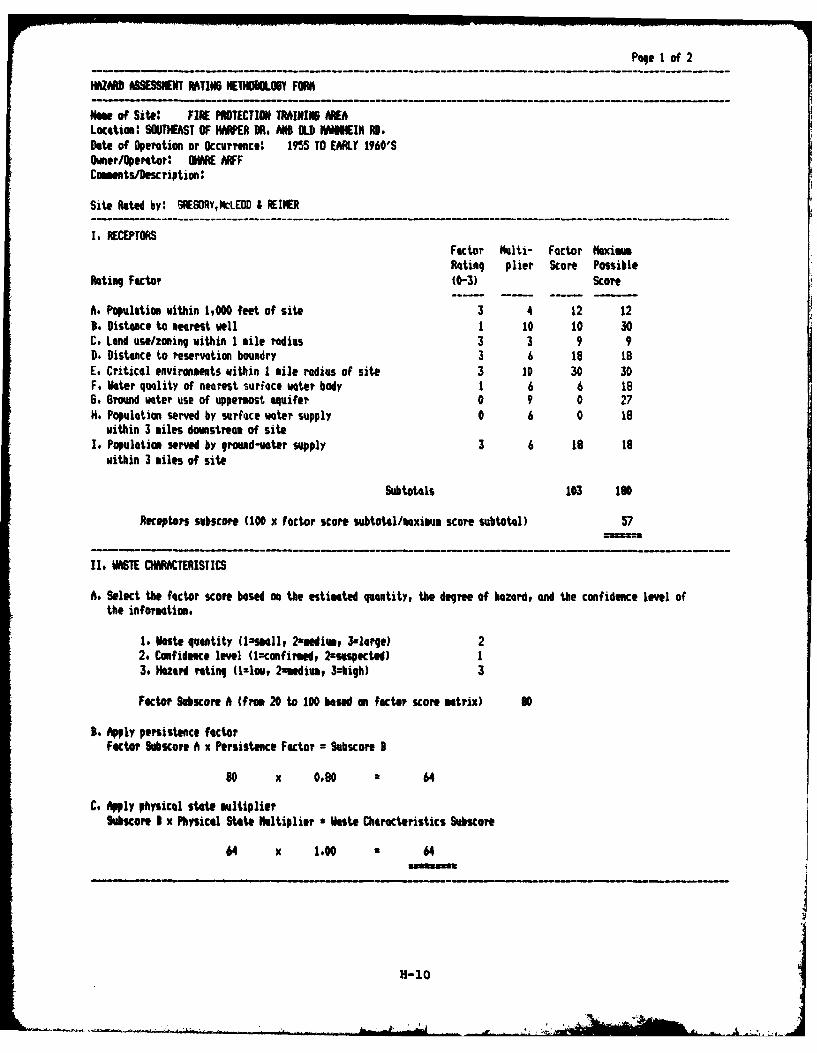
Page I of 2
HAZARD ASSESSIENT RATING AETHOOLSY FON
Nae of Site: FIRE PROTECTION TRAINING ENALocation: SOUTHEAST OF HARPER OR, ND OLD IIN RD.Date of Operation or Occurrence: 1955 TO EARLY 1960'SOwner/Operator: OAE ARFFCmm ts/Description:
Site Rated by: NRE6ORY,NcLEOD 8 REINER
I. RECEPTORSFactor ulti- Factor NaximumRating plier Score Possible
Rating Factor (0-3) Score
A. Population within 1,000 feet of site 3 4 12 12B. Distance to nearest well 1 10 10 30C. Land use/zoning within I mile radius 3 3 9 9D. Distance to reservation boundry 3 6 18 18E, Critical environments within I mile radius of site 3 10 30 30F. Water quality of nearest surface water body 1 6 6 186. Ground water use of uppermost aquifer 0 9 0 27H. Population served by surface water supply 0 6 0 18
within 3 miles downstream of siteI. Population served bY groud-water supply 3 6 is is
within 3 miles of site
Subtotals 103 190
Receptors subscore (100 x factor score subtotal/aximum score subtotal) 57
II. WASTE CHARACTERISTICS
A, Select the factor score based on the estimated quantity, the degree of hazard, and the confidence level ofthe information.
1. 1aste quantity (lssll, 2=edivm, 3lare) 22. Confidence level (lmconfirmed, 2=suspected) 13. Hazard rating (Ilow, 2amedim, 3:high) 3
Factor SUbscoe A (frm 20 to 100 based on factor score mtrix) DO
B. Apply persistence factorFactor SUbScore A x Persistence Factor = Subscore I
80 x 080 = 64
C, Apply physical state multiplierSubscore I x Physical State Hltiplier a Baste Characteristics Subscore
64 x 1.00 64iumumt
11-10
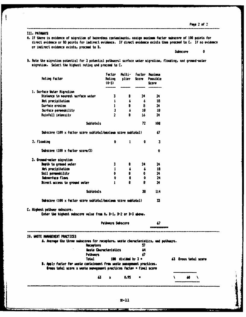
Page 2 of 2
III, PATIMAYSA. If there is evidence of migration of hazardous contaimmnts, asign maxiM factor SUbicore of 100 points for
direct evidence or 80 points far indirect evidence, If direct evideace exists thee proceed to C, If no evidenceor indirect evidence exists, proceed to 3.
Subscore 0
B. Plate the migration potential for 3 potential pathways: surface water migration, flooding, and ground-votermigration. Select the highest rating and proceed to C.
Factor Multi- Factor MaoximumRating Factor Rating plier Score Possible
(0-3) Score
1. Surface Hater igrationDistance to nearest surface water 3 8 24 24Net precipitation 1 6 6 18Surface erosion 1 9 8 24Surface permeability 3 6 is 18Rainfall intensity 2 8 16 24
Subtotals 72 108
Subscore (100 x factor scare subtotl/aximm score subtotal) 67
2. Flooding 0 1 0 3
Subsore (100 X factor scure/3) 0
3. Ground-water migrationDepth togrund water 3 8 24 24Net precipitation 1 6 6 i8Soil permebility 0 8 0 24Subsurface flows 0 9 0 24Direct access to ground water 1 8 8 24
Subtotals 38 114
Subucore (100 X factor score SUbtotal/mXi~M score subtotal) 33
C. Highest pathway subacoretLater the highest subscore value from At 3-1, D-2 or D-3 above,
Pathways Subscore 67
IV, HASTE NANBEEN PRACTICESAt Averag the three suores for recptors, NWt charactristics, Ond pathways,
Recepts 57Haste Characteristics U4Pathways 67Total 168 divided by 3 a 63 Bes total score
3. Anly factor for uaste contaiment from waSte amgment practices.BraS total score X waste managMt pracies factor fimal scOre
63 x *JS5 do6
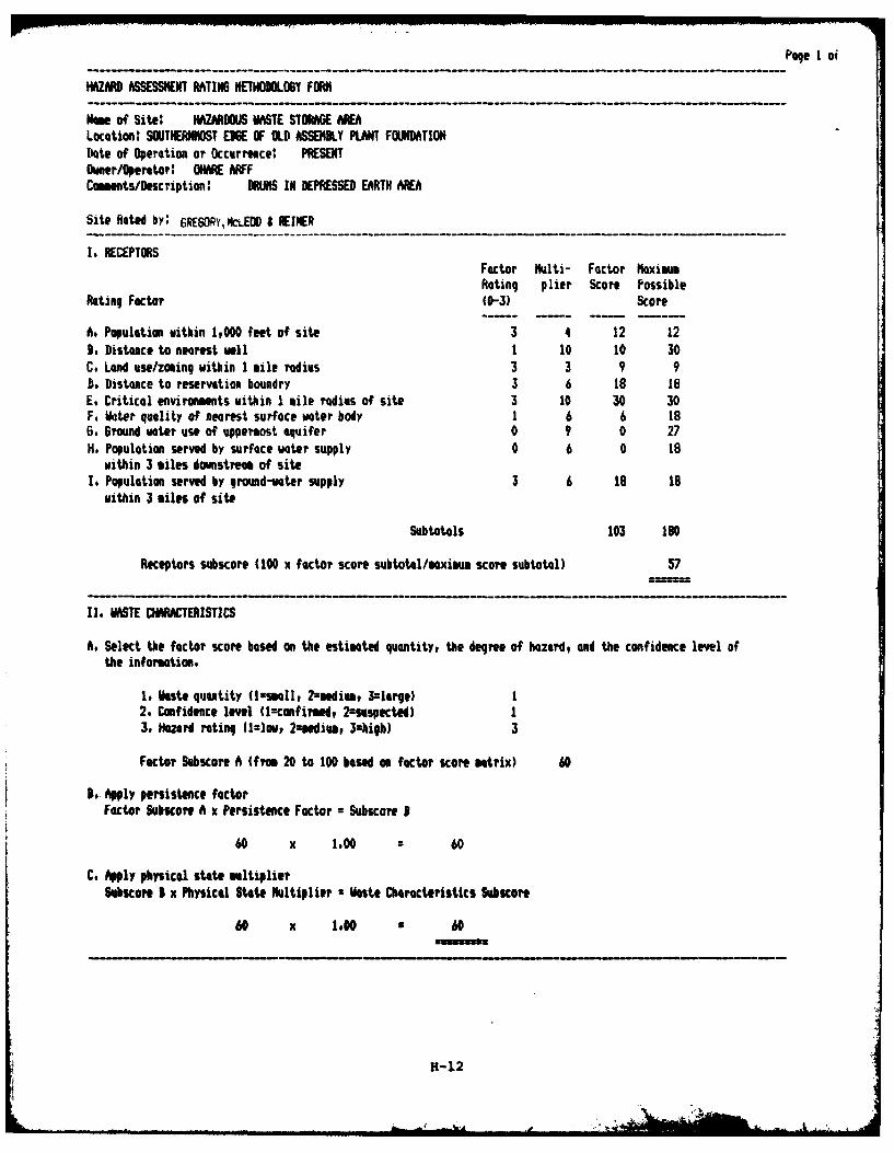
Page I oi
HAZARD ASSESSMENT RATIN6 METHONLOGY FORM
Ne of Site: HAZARDOUS WASTE STORAGE AREALocation: SOUTHERNMOST EDGE OF OLD ASSEMBLY PLANT FOINDATIONDate of Operation or Occurrence: PRESENTOwner/Operttor: OIHRE AIFFCmets/Description: DRIJNS IN DEPRESSED EARTH AA
Site Rated by: 6REW YPCLED I REINER
I. RECEPTORSFactor Multi- Factor Maximum
Rating plier Score PossibleRating Factor (0-3) Score
A. Population within 1,000 feet of site 3 4 12 12B. Distance to nearest well 1 10 10 30C. Land use/zoming within 1 mile radius 3 3 9 9D. Distance to reservation boundry 3 6 18 18E. Critical environments within 1 mile radius of site 3 10 30 30F. Voter quality of nearest surface water body 1 6 6 186. Ground water use of uppermst aquifer 0 9 0 27H. Population served by surface water supply 0 6 0 I8
within 3 miles downstream of siteI. Population served by ground-water supply 3 6 19 18
within 3 miles of site
Subtotals 103 180
Receptors subscore (100 x factor score subtot4l/mximum score subtotal) 57
II. VASTE CHARACTERISTICS
A. Select the factor score based on the estimated quantityr the degree of hazard, and the confidence level ofthe informtion,
to Waste quantity (1:smll, 2=mediam, 3=large) I2. Confidence level (1:confirmed, 2=-uspctW) 13. Hazard rating (lul=Io 2mdiur, 3ahigh) 3
Factor Subscore A (fron 20 to 100 based on factor score matrix) 60
bA Apply persistence factorFactor Subscore A x Persistence Factor = Subscore B
60 x 1.00 60
C. Apply physical state multiplierSubscore 3 x Physical State Multiplier a Waste Characteristics Subiscore
60 x 1.00 60
H-12
vA I• .. L • -.
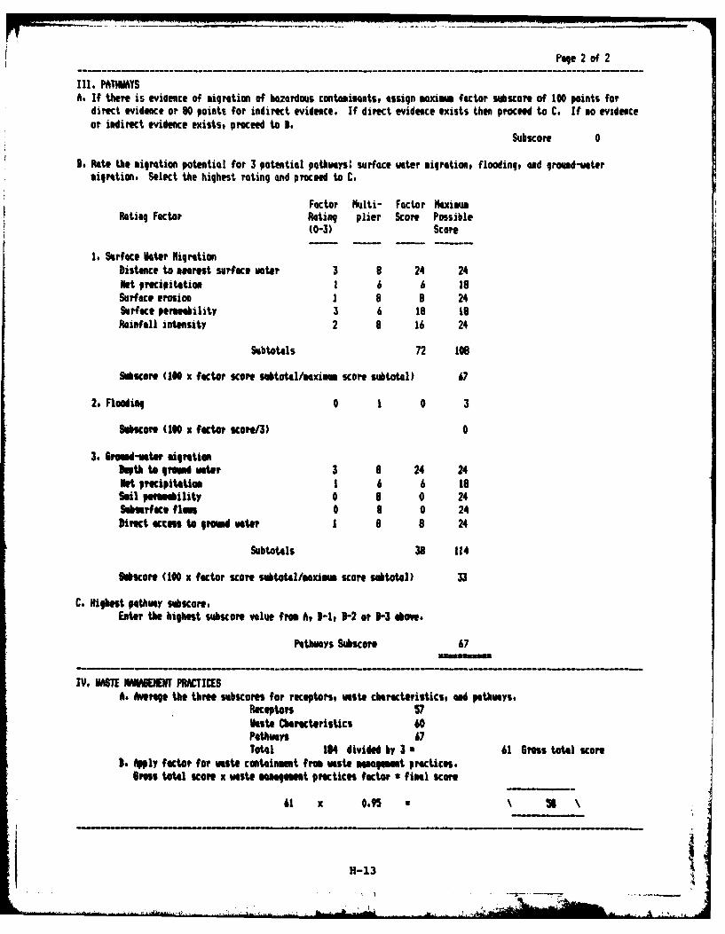
Pale 2 of 2
III, PATAYTSA. If there is evidence of migration of hazardous contaminants, assign maxim factor subscore of 100 points for
direct evidence or 90 points for indirect evidence. If direct evidence exists then proceed to C. If no evidenceor indirect evidence exists, proceed to I,
Subscore 0
B. Rate the migration potential for 3 potential pthways: surface water migration, floodinq, and ground-wotermigration. Select the highest rating and proceed to C.
Factor tilti- Factor MaximmRating Factor Rating plier Score Possible
(0-3) Score
1. Surface Vater igrationDistance to nearest surface voter 3 9 24 24Net precipitation 1 6 6 isSurface erosion 1 8 8 24Surface permeability 3 6 18 1Rainfall intensity 2 8 16 24
Subtotals 72 toe
Subscore (100 x factor score subtot4l/aximum score subtotal) 67
2, Flooding 0 1 0 3
SuhcOe (100 x factor scoe/3) 0
3. 6mid-water igrationDepth to 111ni Wter 3 9 24 24Net precipitation 1 6 6 16Sil pemaility 0 8 0 24Sburface flaft 0 0 0 24Direct access to rmd uter I a B 24
Subtotals 38 114
micore (100 x factor score subtotal/maximm score subtotal) 33
C, Highest pathway sabucore.Enter the highest subscore value from A, 3-1, 3-2 or 1-3 abow.
Pathways Subscore 67
IV. MABT IWMIENENT PACTICESAt Average the three subscores for receptors, waste characteristics, ad pathways.
Receptors 57Veste Chracteristics 60Pathwas 67Total 164 divided by 3 a 61 Gross total score
3. Apply facto? for waste containment from waste management practices.Bras total score x waste mNnment prctices factor * fial score
61 x 0.95 \ 5 \
H1-13
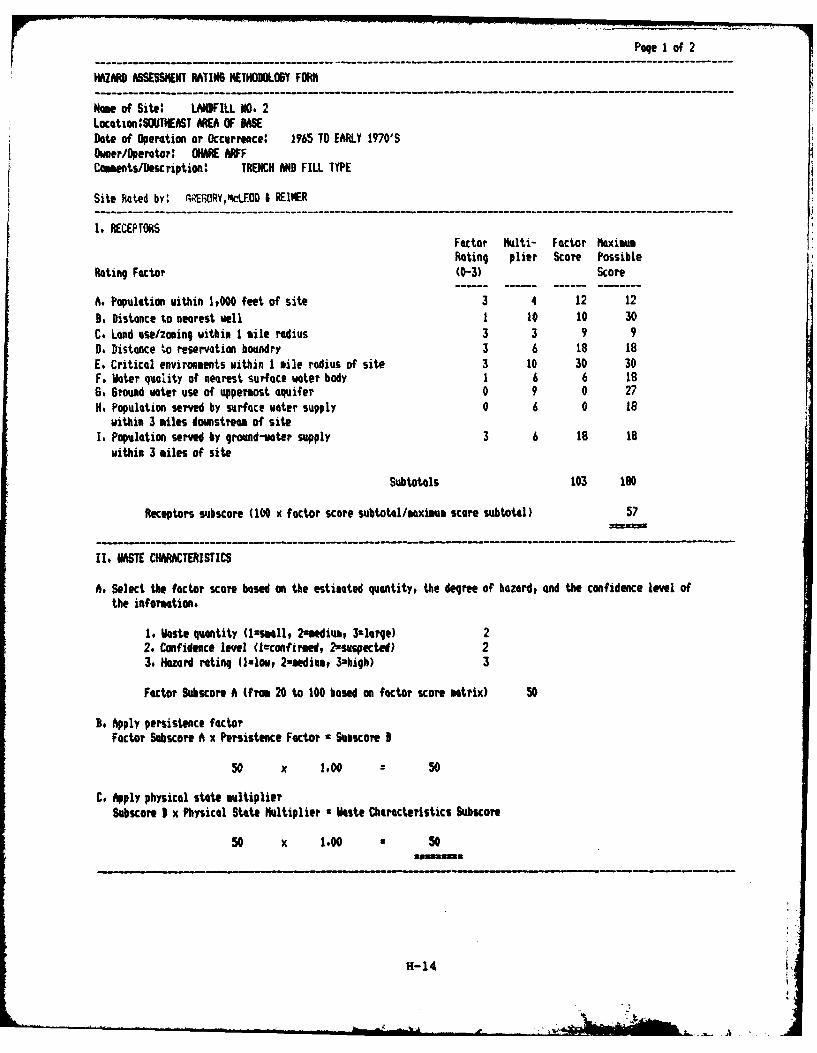
Page I of 2
HAZARD ASSESSMENT RATING HETHODOLOUY FORM
Name of Site; LANDFILL NO. 2Location:SOUTI.AST O OF BASEDate of Operation or Occurrence: 1965 TO EARLY 1970'SOmer/Operator: OARE ARFFComets/escription: TRENCH AND FILL TYPE
Site Rated by' GREORY,-LEOD I REINER
1. RECEPTORSFactor Mlti- Factor MaximumRating plier Score Possible
Rating Factor (0-3) Score
A. Population within 1,000 feet of site 3 4 12 12
B, Distance to nearest well 1 10 10 30C. Land use/zoning within I mile radius 3 3 9 9D. Distance to reservation boundry 3 6 18 18E. Critical environments within 1 mile radius of site 3 10 30 30F. Water quality of nearest surface water body 1 6 6 186. Ground water use of uppermost aquifer 0 9 0 27H, Population served by surface water supply 0 6 0 18
within 3 miles domstream of siteI, Population served by ground-water supply 3 6 18 18
within 3 miles of site
Subtotals 103 180
Receptors subscore (100 x factor score subtotl/maximum score subtotal) 57
II. WASTE CH ARACTERISTICS
A. Select the factor score based om the estimated quantity, the degree of hazard, and the confidence level ofthe information.
1. Waste quantity (l=smll, 2=mediu, 3=large) 22. Confidence level (lcconfired, 2-suspected) 23. Hazard rating (1low, 2=medium, 3=high) 3
Factor Subscore A (from 20 to 100 based on factor score matrix) 50
Be Apply persistence factorFactor Subscore A x Persistence Factor c Suoscore I
50 x 1,00 50
C, Aply physical state multiplierSubscore I x Physical State Multiplier a Waste Characteristics Subscore
50 x 1.00 - 50
H-14
V - A
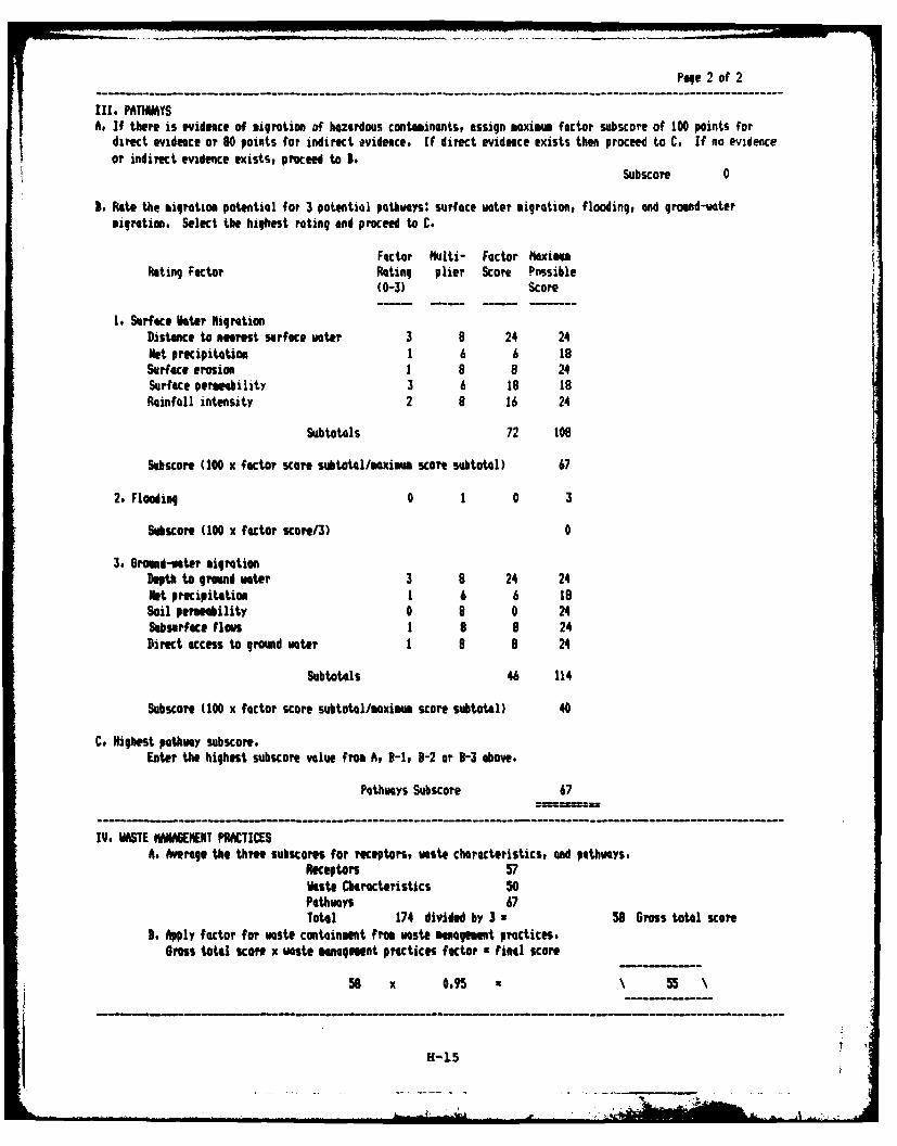
Page 2 of 2
III. PATHWAYSAs If there is evidence of migration of hazardous containants, assign maxim factor subscore of 100 points for
direct evidence or 80 points for indirect evidence. If direct evidence exists then proceed to C. If no evidenceor indirect evidence exists, proceed to 3.
Subscore 0
I. Rate the migration potential for 3 potential pathways: surface voter migration, flooding, and ground-votermigration. Select the highest rating and proceed to C.
Factor Mlti- Factor MaximmRating Factor Rating plier Score Possible
(0-3) Score
1. Surface Nater NigrationDistance to nearest surface voter 3 8 24 24Net precipitation 1 6 6 19Surface erosion 1 8 8 24Surface permeability 3 6 18 18Rainfall intensity 2 8 16 24
Subtotals 72 10e
Subscore (100 x factor score subtotl/maximu score subtotal) 67
2. Flooding 0 1 0 3
Suhscore (100 x factor score/3) 0
3. Grond-ater migrationDepth to ground water 3 8 24 24Net precipitation 1 6 6 18Soil permeability 0 8 0 24Subsurface flows 1 8 8 24Direct access to ground water 1 8 8 24
Subtotals 46 114
Subscore (100 x factor score subtotl/mxim score subtotal) 40
C. Highest pathmay subscore.Enter the highest subscore value from A, I-l, B-2 or 3-3 above.
Pathways Subscore 67
IV. WASTE MAGEHENT PRACTICESA. Average the three subscores for receptors, aste characteristics, and pathways.
Receptors 57Waste Characteristics 50Pathways 67Total 174 divided by 3 - 58 6ross total score
3, Apply factor for waste containment from waste management practices.Oross total score x waste management practices factor a final score
58 x 0.95 55
H-15
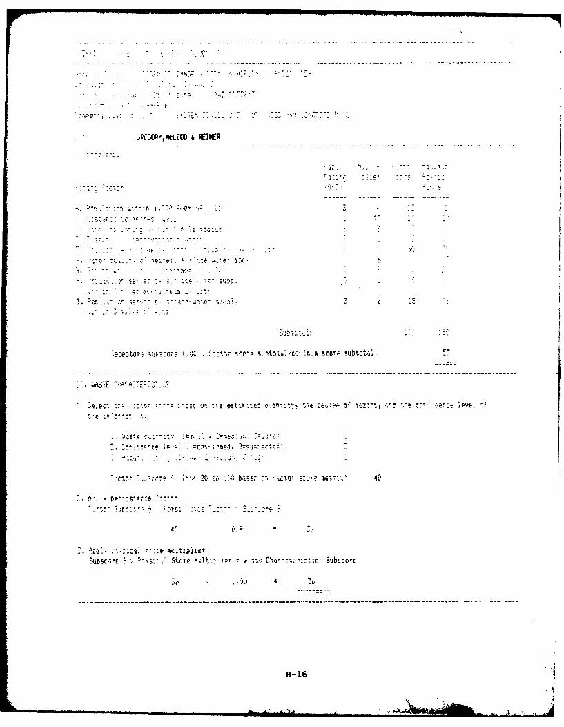
:-'~ ~ - --- - - - - - - - - - - - ---
.,pEWQY,MtLEOD & FINR
P 7r -in !1:
-, ',P+ : + '- 4 . " <" -A-
. L "-: . "---- '. -:: " '.; -'"
-, - e C o' . -- F..- -r: 8--.+r:..:, -.- " S t lll/,;;,.l,5 0' !lb.'.]
-o-:" T++.c ;-.-;: :- 7 P
;ceot rs .. . re Cc. s..... . sc sub
WA "E;+ -" A Aorr 7 t
:mCc. I E eSt- iwte C 1oJQ"i Vic &;e &%-o a~z cU c- er,: !eve- :4
: . =.n -'.. i-, : - 1 E, ,_h
- -'Iu,--,---I'
, , tr ,,0 b.EaC-rnn - o s:-- 40
-' Ac: *DE'::S SC 5-.
H-16 '
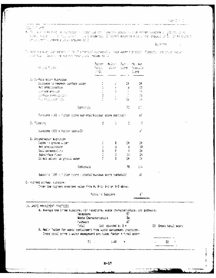
A .- -- - - - .-..-- - ------
-S c p La t -I.,'-
-et .-. on 6.--e 14 24 -- "p",e :11011e
So , Af
Susn-ce Enaetsr-ee~~e 24
D-ece c , 40 waerS
est p.he, : - -
Sgsere :2D ., l !'soTe vai3,
V c )Subs.$oceor "I 22n-ecWaste eeoraccoi-iswater32
EUbtotijs 67 '
The the dividedt bosor ve2 Gros Ata F-. -2o 83 b
A.~ l Avr ctor t'ee wstnscontae mn- rertrs w onste hrte ratis n ctwarcn rne, z -e); ~st saaecept r m ,cs-atr a cr
WasteCharaterisics 3
H1-17
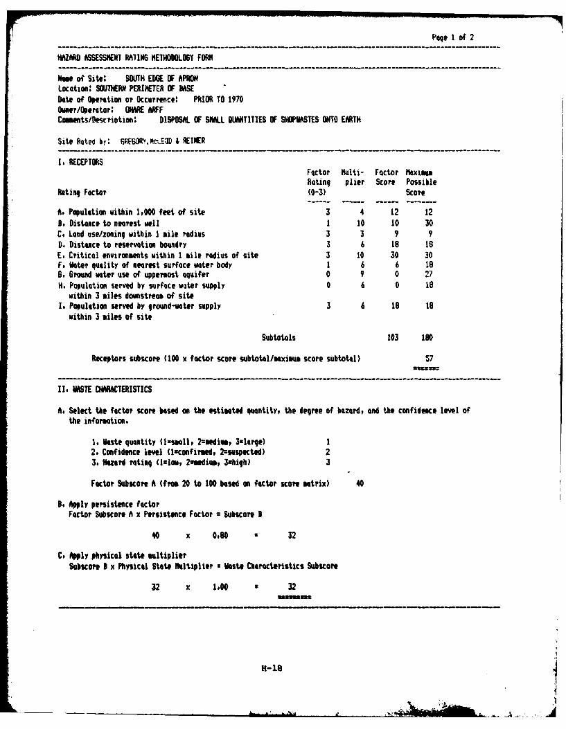
Page 1 of 2
HAZARD ASSESSMENT RATING METHODOLOGY FORM
Nae of Site: SOUTH EDGE OF APRONLocation: SOUTHERN PERIMETER OF BASEDate of Operation or ccurrence: PRIOR TO 1970Owner/Operator: OHNARE ARFFCe ts/escription: DISPOSAL OF SMALL QUANTITIES OF SHOPASTES ONTO EARTH
Site Ratea by: 6E6OW .,n.E3D I REINER
I, RECEPTORSFactor Multi- Factor MaximumRating plier Score Possible
Rating Factor (0-3) Score
A. Population within 1,000 feet of site 3 4 12 12B, Distance to nearest well 1 10 10 30C, Land use/zoning within I mile radius 3 3 9 9
D. Distance to reservation boundry 3 6 18 18E. Critical environments within 1 mile radius of site 3 10 30 30F, Hater quality of nearest surface water body 1 6 6 186. Ground water use of uppermost aquifer 0 9 0 27H. Population served by surface woter supply 0 6 0 18
within 3 miles domstream of siteI. Population served by ground-water supply 3 6 16 18
within 3 miles of site
Subtotals 103 180
Receptors subscore (100 x factor score subtotal/maxime score subtotal) 57
II. MASTE CHARACTERISTICS
A. Select the factor score based on the estimated quantity, the degree of hazard, and the confidence level ofthe information.
1, Nste quantity (lsmall, 2-medium, 3=latqe) 12. Confidence level (luconfirmed, 2=sespected) 23, Hazard rating (llow, 2xmdim, 3zhiqh) 3
Factor Subscore A (Ifm 20 to 100 based on factor score matrix) 40
3. Apply persistence factorFator Subcore A x Persistence Factor = Subscore B
40 x 0080 32
C, Apply physical state multiplierSubscore I x Physical State ltiplier a Waste Characteristics Subscore
32 x 1.00 * 32asamlm.
H-18
A1
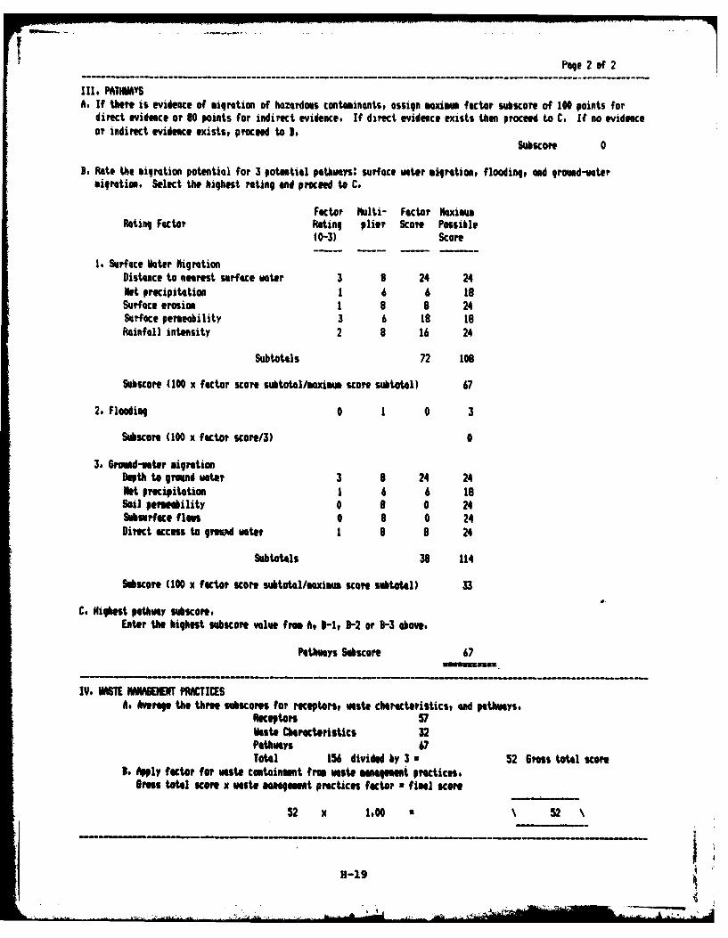
Page 2 of 2
IN, PATMA S
A. If there is evidence of migration of hazardous contaminants, assign maxim factor subscore of 100 points fordirect evidence or 60 points for indirect evidence. If direct evidence exists then proceed to C. If no evidenceor indirect evidence exists, proceed to I.
Subscore 0
B. Rate the migration potential for 3 potential pathways: surface water milration, flooding, ad grond-iatermigration. Select the highest rating and proceed to C.
Factor Nulti- Factor MaxiumRating Factor Rating plier Score Possible
(0-3) Score
1. Surface Nater higrationDistance to nearest surface uater 3 8 24 24Net precipitation 1 6 6 i8Surface erosion 1 8 8 24Surface permeability 3 6 18 toRainfall intensity 2 8 16 24
Subtotals 72 to
Subscore (100 x factor score subtotal/maximum score subtotal) 67
2. Flooding 0 1 0 3
Subscora (100 x factor score/3) 0
3. Groud-ater migrationDepth tog round water 3 8 24 24Net precipitation 1 6 6 18Soil permability 0 8 0 24Sobserfece flows 0 8 0 24Direct access to grWudw ater 1 8 8 24
Subtotals 38 114
SubScore (100 x factor score subtotal/mxim score subtotal) 33
C. Highest pathway subscore.Eter the highest subscore value frm t I-1, 3-2 or B-3 above,
Pathways Subecore 67
IV, WMSTE MANABEHENT PRTISAs Average the three subscores for receptors, waste characteristics, and pathways.
Receptors 57iksto Chracteristics 32Pathways 67Total 156 divided by 3 * 52 Gress total score
I. Apply factOr for waste containment from waste 0ngmt practices.Bross total score x Waste nnagm9 t practices factor • final score
52 x 1,00 52
B-19

HA ASSESSNENT RATING METHOURLOSY FORM
Name of site: VEHICLE MAINTENANCE FACILITYLocation: 1D. 5,1EARDate of Operation or Occurrence: PRIOR TO 1977Omer/Operttor: ONARE WFCoomts/Dscription MASTE OIL DISPOSED OF ONTO GROWND
Site Rated by: 6E60PY,wLEOD I REIER--------------------------------------------------------
I. RECEPTORSFactor Mlti- Factor MaximumRating plier Score Possible
Rating Factor (0-3) Score
A. Population within 1,000 feet of site 3 4 12 12B, Distance to nearest well 1 10 10 30C. Lend use/zoning within I mile radius 3 3 9 9D. Distance to reservation boundry 3 6 18 18E, Criticol environments within 1 tile radius of site 3 10 30 30F. Water quality of nearest surface water body 1 6 6 186. Ground water use of uppermost aquifer 0 9 0 27H. Population served by surface water supply 0 6 0 18
within 3 iles downstream of siteI. Population served by gpond-water supply 3 6 18 18
within 3 miles of site
Subtotals 103 160
Receptors subscore (100 x factor score subtotal/maximm score subtotal) 57
II. SE CHARACTERISTICS
A. Select the factor score based on the estimated quantity, the degree of hazardt and the confidence level ofthe information,
1o ikste quantity (1:smll, 2=medim, 3-ltrqe) I2. Confidence level (Isconfirmed, 2zSMpetd) 13, Hazard rating (l=low 2nmedium, 3=hiqh) I
Factor Subscore A (from 20 to 100 based on factor score mtrix) 30
3. Apply persistence factorFactor Subscore A x Persistence Factor = Subscore I
30 x 0.80 24
C. Apply physical state multiplierSubscore I x Physical State Multiplier • Waste Characteristics SUbcoe
24 x 1.00 • 24
H-20
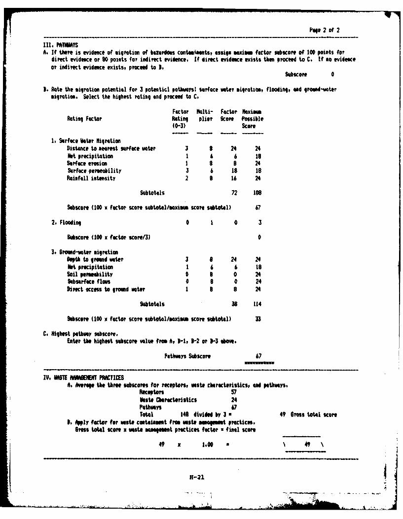
Page 2 of 2
Il. PATIMAYSA. If there is evidence of migration of hazardous contamients, assign mexism factor ugbcore of 100 points for
direct evidence or 80 points for indirect evidence. If direct evidence exists then proceed to C. If no evidenceor indirect evidence exists, proceed to 3,
Subscore 0
B. Rate the sigration potential for 3 potential pathways: surface water miqration, flooding, and ground-watermigration. Select the highest rating end proceed to C.
Factor Multi- Factor MaximumRating Factor Rating plier Score Possible
(0-3) Score
1t Surface Nater NigrationDistance to nearest surface water 3 8 24 24Net precipitation 1 6 6 18Surface erosion 1 8 8 24Surface permeability 3 6 18 18Rainfell intensity 2 8 16 24
Subtotals 72 108
Subscore (100 x factor scorte subtoal/mxiM scoe subtotal) 67
2. Flooding 0 1 0 3
Subscore (100 x factor score/3) 0
3. Ground-water migrationDepth to ground water 3 8 24 24Net precipitation 1 6 6 18Soil permeability 0 8 0 24Subsurface flows 0 8 0 24Direct access to ground water 1 8 a 24
Subtotals 36 114
Sobicore (100 x factor score SUbtotAl/eximm score subtotal) 33
C. Highest pathway bSCore,Enter the highest subcore value from A 3-1, 3-2 or 3-3 abov,
Pathways Subscore 67
IV, HaSTE HANABENM PRACTICESA. Average the three subscores for receptors, Waste cbarctristics, d pathways.
Receptors 571aste Characteristics 24Pathways 67Total 148 divided by 3 * 49 Gross total score
3, Apply factor for wate containment frm waste ama mest practices,Gross total score x Vaste "q1100t practices fc tor •final score
49 x 1.00 \ 49
H-21
• .. - -.
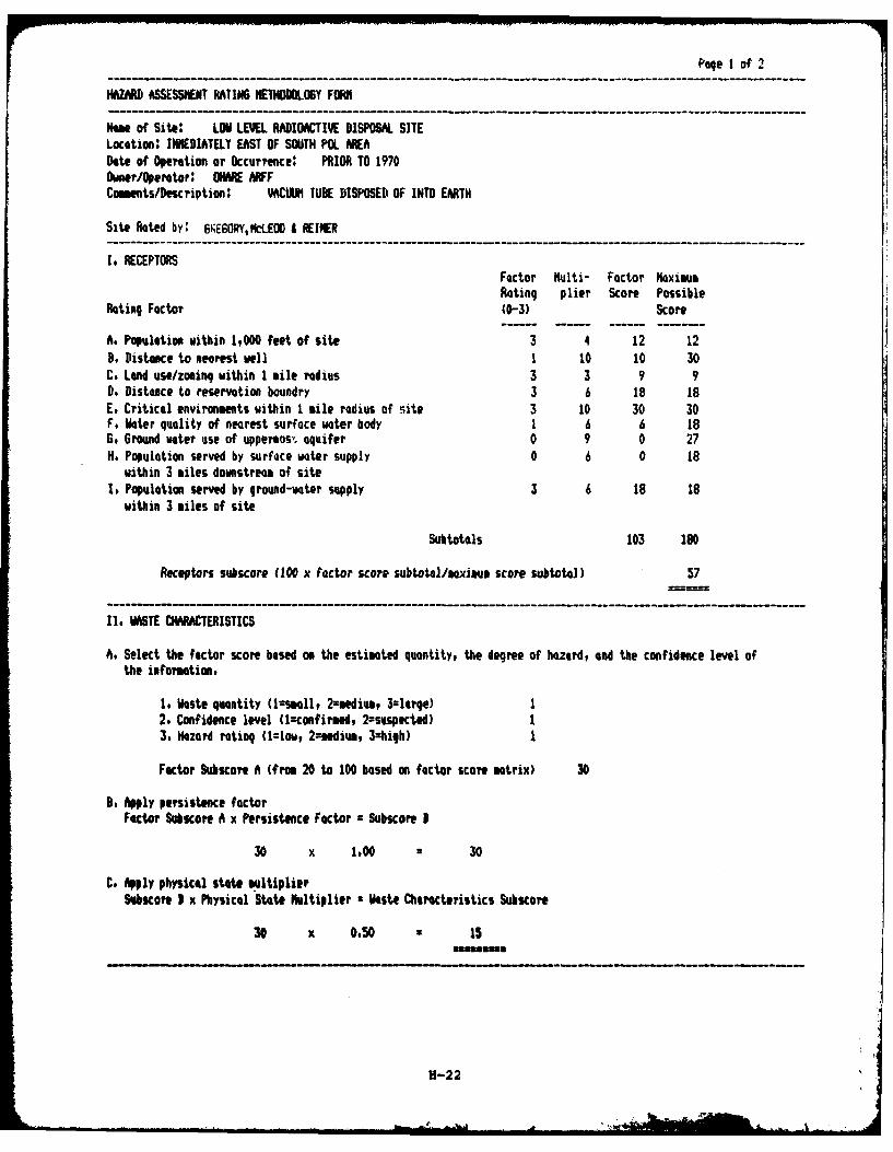
Page I of 2
HAMZAR ASSESSMENT RATING NETHODOLOY FORM
Name of Site: LOW LEVEL RADI ACTIVE DISPOSAL SITELocation: IMMEDIATELY EAST OF SOUTH P0L AREADate of Operation or Occurrence: PRIOR TO 1970Owner/Operator: NARE ARFFComests/escription: VACUUM TUBE DISPOSED OF INTO EARTH
Site Rated by: GNE6ORYMcLEOD I REINER----------------------------------- ----------------- --- ------ ------ --------- -
It RECEPTORSFactor Multi- Factor MaximumRating plier Score Possible
Rating Factor (0-3) Score
A. Population within 1,000 feet of site 3 4 12 12B. Distance to nearest well 1 10 10 30C. Land use/zoning within 1 mile radius 3 3 9 90. Distance to reservation boundry 3 6 18 18E. Critical environments within I tile radius of site 3 10 30 30F, Water quality of nearest surface water body 1 6 6 18G, Ground water use of uppermos't, aquifer 0 9 0 27H. Population served by surface water supply 0 6 0 18
within 3 miles downstream of siteI, Population served by ground-voter supply 3 6 18 18
within 3 miles of site
Subtotals 103 180
Receptors subscore 1100 x factor score subtotal/maxiasu score subtotal) 57
I. WASTE CHARACTERISTICS
A. Select the factor score based on the estimated quantity, the degree of hazerd, and the confidence level ofthe information.
I. Waste quantity (lcsmll, 2:mediua, 3zlerge) 12. Confidence level (lnconfirsed, 2-sUspKted) 13. Hazard rating (1=low, 2=medium, 3=high) 1
Factor Subscore A (frm 20 to 100 based on factor score matrix) 30
S. Apply persistence factorFector Subcore A x Persistence Factor = Subscore B
30 x 1.00 * 30
C. Apply physical state multiplierSMscore I x Physical State Multiplier a Waste Characteristics Subscore
30. x 0.50 * 15
H-22
. , .. ...... .... . . . ;,, ,. ,,: ,yv.,, , .. . . ..t.

Page 2 of 2
Il. PATHWAYSA. If there is evidence of migration of hazardous contaminants, assign mxism factor subscore of 100 points for
direct evidence or 80 points for indirect evidence. If direct evidence exists then proceed to C, If no evidenceor indirect evidence exists, proceed to B,
Subscore 0
8, Rote the migration potential for 3 potential pathways: surface voter migration, flooding, and groud-vatermigrtion. Select the highest rating and proceed to C.
Factor Mlti- Factor MximRating Factor Rating plier Score Possible
(0-3) Score
I. Surface Mater igrationDistance to nearest surface water 3 8 24 24Net precipitation 1 6 6 18Surface ersion 1 9 8 24Surface permeability 3 6 18 18Rainfall intensity 2 8 16 24
Subtot4ls 72 109
Sobscore (100 x factor score suhbtotol/maximm score subtotal) 67
2. Flooding 0 1 0 3
Slscore (100 x factor score/3) 0
3, 6round-voter migrationDepth to ground ater 3 8 24 24Not precipitation 1 6 6 18Soil permeuility 0 8 0 24Suburface flows 0 8 0 24Direct access to ground voter 1 8 8 24
Subtotals 38 114
Subicore (100 x factor score subtotolmxium score subtotGl) 33
C. Highest pathway subscore.Enter the highest subscore value from A, 1-1, B-2 or 3-3 above
Pathwys Sbscore 67
IV. UAS MUIAGIEENT PRACTICESA. Averag the three subKcores for receptors, waste cracteristics, and pathwOys,
Receptors 57Waste Charcteristics 15Pathways 67Total 139 divided by 3 a 46 6ress total score
s. Apply fector for waste contalnamnt from vaste moatement practices.Uts tot4l scOre x waste man t prctices factor • final score
46 x 0,95 44
H-23
00* Ir
APPENDIX I
REFERENCES
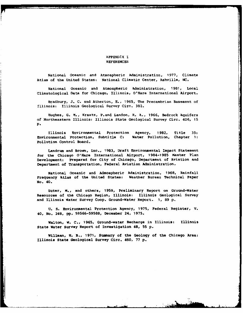
APPENDIX I
REFERENCES
National Oceanic and Atmospheric Administration, 1977, Climate
Atlas of the United States: National Climatic Center, Ashville, NC.
National Oceanic and Atmospheric Administration, 1981, LocalClimatological Data for Chicago, Illinois, O'Hare International Airport.
Bradbury, J. C. and Atherton, E., 1965, The Precambrian Basement ofIllinois: Illinois Geological Survey Circ. 382.
Hughes, G. M., Kraatz, P.and Landon, R. A., 1966, Bedrock Aquifersof Northeastern Illinois: Illinois State Geological Survey Circ. 406, 15p.
Illinois Environmental Protection Agency, 1982, Title 35:Environmental Protection, Subtitle C: Water Pollution, Chapter 1:Pollution Control Board.
Landrum and Brown, Inc., 1983, Draft Environmental Impact Statementfor the Chicago O'Hare International Airport, 1984-1985 Master PlanDevelopment: Prepared for City of Chicago, Department of Aviation andDepartment of Transportation, Federal Aviation Administration.
National Oceanic and Admospheric Administration, 1968, RainfallFrequency Atlas of the United States: Weather Bureau Technical PaperNo. 40.
Suter, M., and others, 1959, Preliminary Report on Ground-WaterResources of the Chicago Region, Illinois: Illinois Geological Surveyand Illinois Water Survey Coop. Ground-Water Report. 1, 89 p.
U. S. Environmental Protection Agency, 1975, Federal Register, V.40, No. 248, pp. 59566-59588, December 24, 1975.
Walton, W. C., 1965, Ground-water Recharge in Illinois: IllinoisState Water Survey Report of Investigation 48, 55 p.
Willman, H. B., 1971, Summary of the Geology of the Chicago Area:Illinois State Geological Survey Circ. 460, 77 p.
APPIE)DIX JGLOSSARY OF TERMINOLOGY AND ABBREVIATIONS
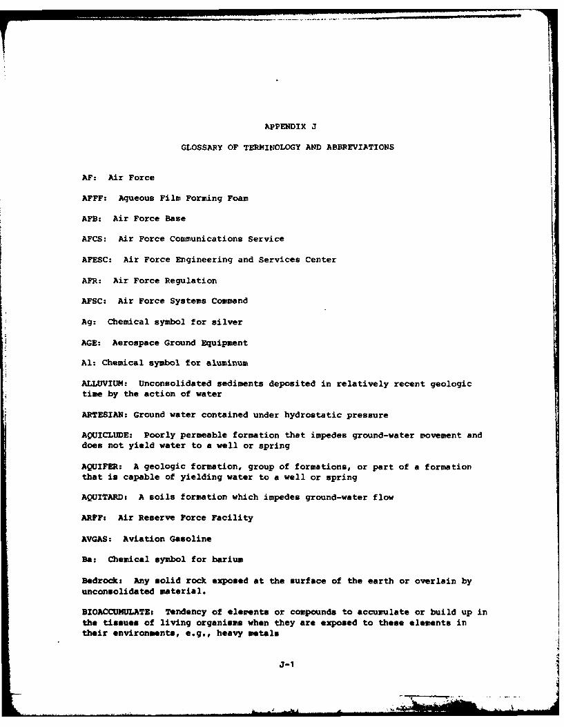
APPENDIX J
GLOSSARY OF TERMINOLOGY AND ABBREVIATIONS
AF: Air Force
AFFF: Aqueous Film Forming Foam
AFB: Air Force Base
AFCS: Air Force Communications Service
AFESC: Air Force Engineering and Services Center
AFR: Air Force Regulation
AFSC: Air Force Systems Command
Ag: Chemical symbol for silver
AGE: Aerospace Ground Equipment
Al: Chemical symbol for aluminum
ALLUVIUM: Unconsolidated sediments deposited in relatively recent geologictime by the action of water
ARTESIAN: Ground water contained under hydrostatic pressure
AQUICLUDE: Poorly permeable formation that impedes ground-water movement anddoes not yield water to a well or spring
AQUIFER: A geologic formation, group of formations, or part of a formationthat is capable of yielding water to a well or spring
AQUITARD: A soils formation which impedes ground-water flow
ARFF: Air Reserve Force Facility
AVGAS: Aviation Gasoline
Ba: Chemical symbol for barium
Bedrock: Any solid rock exposed at the surface of the earth or overlain byunconsolidated material.
BIOACCUHULATE: Tendency of elements or compounds to accumulate or build up inthe tissues of living organisms when they are exposed to these elements intheir environments, e.g., heavy metals
J-1
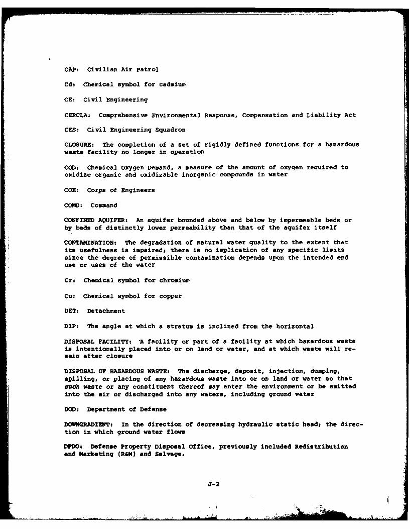
CAP: Civilian Air Patrol
Cd: Chemical symbol for cadmium
CE: Civil Engineering
CERCLA: Comprehensive Environmental Response, Compensation and Liability Act
CES: Civil Engineering Squadron
CLOSURE: The completion of a set of rigidly defined functions for a hazardouswaste facility no longer in operation
COD: Chemical Oxygen Demand, a measure of the amount of oxygen required tooxidize organic and oxidizable inorganic compounds in water
COE: Corps of Engineers
COMD: Command
CONFINED AQUIFER: An aquifer bounded above and below by impermeable beds orby beds of distinctly lower permeability than that of the aquifer itself
CONTA4INATION: The degradation of natural water quality to the extent thatits usefulness is impaired; there is no implication of any specific limitssince the degree of permissible contamination depends upon the intended enduse or uses of the water
Cr: Chemical symbol for chromium
Cu: Chemical symbol for copper
DET: Detachment
DIP: The angle at which a stratum is inclined from the horizontal
DISPOSAL FACILITY: 'A facility or part of a facility at which hazardous wasteis intentionally placed into or on land or water, and at which waste will re-main after closure
DISPOSAL OF HAZARDOUS WASTE: The discharge, deposit, injection, dumping,spilling, or placing of any hazardous waste into or on land or water so thatsuch waste or any constituent thereof may enter the environment or be emittedinto the air or discharged into any waters, including ground water
DOD: Department of Defense
DOWNGRADIENT: In the direction of decreasing hydraulic static head; the direc-tion in which ground water flows
DPDO: Defense Property Disposal Office, previously included Redistributionand Marketing (R&M) and Salvage.
J-2
.. . ... A
DUMP. An uncovered land disposal site where solid and/or liquid wastes are
deposited with little or no regard for pollution control or aesthetics; dumps
are susceptible to open burning and are exposed to the elements, disease vec-
tors and scavengers
EOD: Explosive Ordnance Disposal
EFFLUENT: A liquid waste discharge from a manufacturing or treatment process,in its natural state, or partially or completely treated, that discharges intothe environment
EP: Extraction Procedure, the EPA's standard laboratory procedure forleachate generation
EPA: U.S. Environmental Protection Agency
EROSION: The wearing away of land surface by wind or water
FAA: Federal Aviation Administration
FACILITY: Any land and appurtenances used for the treatment, storage and/ordisposal of hazardous wastes
Fe: Chemical symbol for iron
FLOOD PLAIN: The lowland and relatively flat areas adjoining inland and coast-al areas of the mainland and off-shore islands, including, at a minimum, areassubject to a one percent or greater chance of flooding in any given year
FLOW PATH: The direction or movement of ground water and any contaminantsthat may be contained therein, as governed principally by the hydraulicgradient
GC/MS: Gas chromatograph/mass spectrophotometer, a laboratory procedure foridentifying unknown compounds
GROUND WATER: Water beneath the land surface that is under atmospheric orartesian pressure
GROUND WATER RESERVOIR: The earth materials and the intervening open spacesthat contain ground water
HALF-LIFE: The time required for half the atoms present in radioactive sub-stance to decay
HARDFILLs Disposal sites receiving construction debris, wood, miscellaneousspoil material
HARM: Hazard Assessment Rating Methodology
HAZARDOUS WASTE: A solid waste, or combination of solid wastes, which because
of its quantity, concentration, or physical, chemical or infectious character-
istics may cause or significantly contribute to an increase in mortality or anincrease in serious, irreversible, or incapacitating reversible illness; or
J-3
pose a substantial present or potential hazard to human health or the environ-ment when improperly treated, stored, transported, or disposed of, or other-wise managed (RCRA)
HAZARDOUS WASTE GENERATION: The act or process of producing a hazardous waste
HEAVY METALS: Metallic elements, including the transition series, which in-clude many elements required for plant and animal nutrition in trace concen-trations but which become toxic at higher concentrations
Hg: Chemical symbol for mercury
HQ: Headquarters
HWMF: Hazardous Waste Management Facility
INCOMPATIBLE WASTE: A waste unsuitable for commingling with another waste ormaterial because the commingling might result in generation of extreme heat orpressure, explosion or violent reaction, fire, formation of substances whichare shock sensitive, friction sensitive, or otherwise have the potential forreacting violently, formation of toxic dusts, mists, fumes, and gases, volatil-ization of ignitable or toxic chemicals due to heat generation in such a man-ner that the likelihood of contamination of ground water or escape of the sub-stance into the environment is increased, any other reaction which might re-sult in not meeting the air, human health, and environmental standard
INFILTRATION: The gradual passing of liquid through matter.
IRP: Installation Restoration Program
JP-4: Jet Fuel
LEACHATE: A solution resulting from the separation or dissolving of solubleor particulate constituents from solid waste or other man-placed medium bypercolation of water
LEACHING: The process by which soluble materials in the soil, such as nu-trients, pesticide chemicals or contaminants, are washed into a lower layer ofsoil or are dissolved and carried away by water
LINER: A continuous layer of natural or man-made materials beneath or on thesides of a surface impoundment, landfill, or landfill cell which restricts thedownward or lateral escape of hazardous waste, hazardous waste constituents orleachate
LOESS: A sediment composed dominantly of silt-size particles that has beendeposited primarily by the wind
LOX: Liquid Oxygen
LYSIMETERS: A vacuum operated sampling device used for extracting pore watersamples at various depths within the unsaturated zone
MIK: Methyl Ethyl Ketone
J-4
.. . , -- -
MGD: million gallons per day
MOA: Military Operating Area
MOGAS: Motor gasoline
Mn: Chemical symbol for manganese
MONITORING WELL: A well used to measure ground-water levels and to obtainsamples
MSL: Mean Sea Level
MUNITION ITEMS: Munitions or portions of munitions having an explosivepotential
MUNITIONS RESIDUE: Non-explosive segments of waste munitions (i.e., bomb
casings)
NCO: Non-commissioned Officer
NCOIC: Non-commissioned Officer In-Charge
NDI: Non-destructive Inspection
NET PRECIPITATION: The amount of annual precipitation minus annual evaporation
NGVD: National Geodetic Vertical Datum
Ni: Chemical symbol for nickel
NPDES: National Pollutant Discharge Elimination System
OEHL: Occupational and Environmental Health Laboratory
ORGANIC: Being, containing or relating to carbon compounds, especially inwhich hydrogen is attached to carbon
O&G: Symbols for oil and grease
OSI: Office of Special Investigations
OVA: Organic Vapor Analyzer
Pbs Chemical symbol for lead
PCB: Polychlorinated Biphenyls; highly toxic to aquatic lifel they persist inthe environment for long period and are biologically accumulative
PERCOLATION: Movement of moisture by gravity or hydrostatic pressure throughinterstices of unsaturated rock or soil
PEREABILITY: The rate at which fluids may move through a solid, porous medium
J-5
PD-680: Cleaning solvent, safety solvent, Stoddard solvent, petroleumdistillate
pH: Negative logarithm of hydrogen ion concentration; measurement of acids andbases
PL: Public Law
POL: Petroleum, Oils and Lubricants
POLLUTANT: Any introduced gas, liquid or solid that makes a resource unfitfor a specific purpose
POTENTIALLY ACTIVE FAULT: A fault along which movement has occurred withinthe last 25-million years
PPM: Parts per million by weight
PRECIPITATION: Rainfall
RCRA: Resource Conservation and Recovery Act
RECHARGE AREA: An area in which water is absorbed that eventually reaches thezone of saturation in one or more aquifers
RECHARGE: The addition of water to the ground-water system by natural or arti-ficial processes
RECON: Reconnaissance
SANITARY LANDFILL: A land disposal site using an engineered method of dispos-ing solid wastes on land in a way that minimizes environmental hazards
SATURATED ZONE: That part of the earth's crust in which all voids are filledwith water
SEISMICITY: Pertaining to earthquakes or earth vibrations
SLUDGE: The solid residue resulting from a manufacturing or wastewater treat-ment process which also produces a liquid stream
SOLID WASTE: Any garbage, refuse, or sludge from a waste treatment plant,water supply treatment, or air pollution control facility and other discardedmaterial, including solid, liquid, semi-solid, or contained gaseous materialresulting from industrial, commercial, mining, or agricultural operations andfrom community activities, but does not include solid or dissolved materialsin domestic sewage; solid or dissolved materials in irrigation return flows;industrial discharges which are point source subject to permits under Section402 of the Federal Water Pollution Control Act, as amended (86 USC 880); orsource, special nuclear, or by-product material as defined by the AtomicEnergy Act of 1954 (68 USC 923)
SPILL: Any unplanned release or discharge of a hazardous waste onto or intothe air, land, or water
J-6
STORAGE OF HAZARDOUS WASTF: Containment, either on a temporary basis or for alonger period, in such a manner as not to constitute disposal of such hazard-ous waste
TAC: Tactical Air Command
TAG: Tactical Airlift Group
TCE: Tetrachloroethylene
TCA: 1,1,1-Tetrachloroethane
TOC: Total Organic Carbon
TOXICITY: The ability of a material to produce injury or disease upon expo-sure, ingestion, inhalation, or assimilation by a living organism
TRANSMISSIVITY: The rate at which water is transmitted through a unit widthunder a unit hydraulic gradient
TREATMENT OF HAZARDOUS WASTE: Any method, technique, or process includingneutralization designed to change the physical, chemical, or biological char-acter or composition of any hazardous waste so as to neutralize the waste orso as to render the waste nonhazardous
UPGRADIENT: In the direction of increasing hydraulic static head; the direc-
tion opposite to the prevailing flow of ground-water
USAF: United States Air Force
USGS: United States Geological Survey
WATER TABLE: Surface of a body of unconfined ground water at which the pres-sure is equal to that of the atmosphere
Zn: Chemical symbol for zinc
J-7
APPENDIX K
INDEX
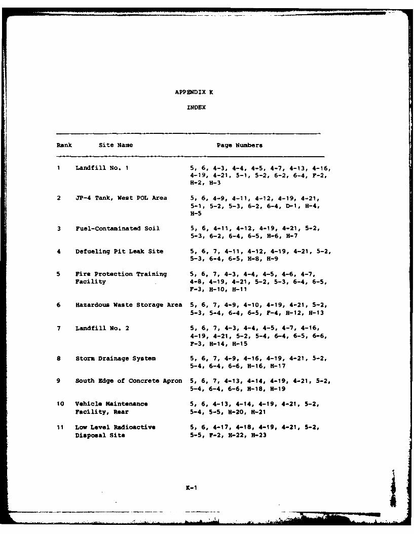
APPENDIX K
INDEX
Rank Site Name Page Numbers
1 Landfill No. 1 5, 6, 4-3, 4-4, 4-5, 4-7, 4-13, 4-16,4-19, 4-21, 5-1, 5-2, 6-2, 6-4, F-2,H-2, H-3
2 JP-4 Tank, West POL Area 5, 6, 4-9, 4-11, 4-12, 4-19, 4-21,5-1, 5-2, 5-3, 6-2, 6-4, D-1, H-4,H-5
3 Fuel-Contaminated Soil 5, 6, 4-11, 4-12, 4-19, 4-21, 5-2,5-3, 6-2, 6-4, 6-5, H-6, H-7
4 Defueling Pit Leak Site 5, 6, 7, 4-11, 4-12, 4-19, 4-21, 5-2,5-3, 6-4, 6-5, H-8, H-9
5 Fire Protection Training 5, 6, 7, 4-3, 4-4, 4-5, 4-6, 4-7,Facility 4-8, 4-19, 4-21, 5-2, 5-3, 6-4, 6-5,
F-3, H-10, H-11
6 Hazardous Waste Storage Area 5, 6, 7, 4-9, 4-10, 4-19, 4-21, 5-2,5-3, 5-4, 6-4, 6-5, F-4, H-12, H-13
7 Landfill No. 2 5, 6, 7, 4-3, 4-4, 4-5, 4-7, 4-16,4-19, 4-21, 5-2, 5-4, 6-4, 6-5, 6-6,F-3, H-14, H-15
8 Storm Drainage System 5, 6, 7, 4-9, 4-16, 4-19, 4-21, 5-2,5-4, 6-4, 6-6, H-16, H-17
9 South Edge of Concrete Apron 5, 6, 7, 4-13, 4-14, 4-19, 4-21, 5-2,5-4, 6-4, 6-6, H-18, H-19
10 Vehicle Kaintenance 5, 6, 4-13, 4-14, 4-19, 4-21, 5-2,Facility, Rear 5-4, 5-5, H-20, H-21
11 Low Level Radioactive 5, 6, 4-17, 4-18, 4-19, 4-21, 5-2,Disposal Site 5-5, F-2, H-22, H-23
K-1
INSTALLATION RESTORATION PROGRAM
PHASE 1 - RECORDS SEARCH
O'HARE AIR RESERVE FORCES FACILITY,
ILLINOIS
Prepared For
UNITED STATES AIR FORCE
HEADQUARTERS
AIR FORCE RESERVE
Robins Air Force Base, Georgia
December 1983
Prepared By
ENGINEERING-SCIENCE57 Executive Park South, Suite S90
Atlanta, Georgia 30329
NOTICE
This report has been prepared for the United States AirForce by Engineering-Science for the purpose of aiding inthe Air Force Installation Restoration Program. It is notan endorsement of any product. The views expressedherein are those of the contractor and do not necessarilyreflect the official views of the publishing agency, the UnitedStates Air Force, nor the Department of Defense.
Copies of the report may be purchased from:
National Technical Information Service5285 Port Royal RoadSpringfield, Virginia 22161
Federal Government agencies and their contractorsregistered with Defense Technical Information Centershould direct requests for copies of this report to:
Defense Technical Information CenterCameron StationAlexandria, Virginia 22314
r
4 , A,
TABLE OF CONTENTS
Page No.
LIST OF FIGURES iii
LIST OF TABLES iv
EXECUTIVE SUMMARY
SECTION I INTRODUCTION 1-1Background 1-1Purpose and Scope of the Assessment 1-2Methodology 1-3
SECTION 2 INSTALLATION DESCRIPTION 2-1Location' Size and Boundaries 2-1Installation History 2-1Organization and Mission 2-5
SECTION 3 ENVIRONMENTAL SEMING 3-1Meteorology 3-1Geography 3-3
Topography and Drainage 3-3Geology 3-6
Stratigraphy 3-6Structure 3-11
Hydrology 3-11Subsurface Hydrology 3-11Surface Hydrology 3-12
Water Use 3-14Water Quality 3-14Biotic Environment 3-17Summary of Environmental Setting 3-17
SECTION 4 FINDINGS 4-1Past Shop and Installation Activity Review 4-1Industrial Operations (Shops) 4-2
Fire Protection Training 4-7Pesticide Utilization 4-7Waste Storage Areas 4-9Fuels Management 4-9Spills and Leaks 4-11
Li
TABLE OF CONTENTS(Continued)
SECTION 4 Description of Past On-Installation Disposal 4-13(Continued) Methods
Landfills 4-13Hardfi 11 4-16Storm Drainage System 4-16Sanitary Sewer System 4-17Low-level Radiation Disposal Site 4-17
Evaluation of Past Disposal Activities and 4-17
SECTION 5 CONCLUSIONS 5-1
SECTION 6 RECOMMENDATIONS 6-1
APPENDIX A BIOGRAPHICAL DATA
APPENDIX B LIST OF INTERVIEWEES
APPENDIX C ORGANIZATIONS AND MISSIONS
APPENDIX D POL TANK INFORMATION
APPENDIX E MASTER LIST OF INDUSTRIAL SHOPS
APPENDIX F PHOIGRAPHS
APPENDIX G HAZARD ASSESSMENT RATING METHODOLOGY
APPENDIX H HAZARD ASSESSMENT RATING FORMS
APPENDIX I REFERENCES
APPENDIX J GLOSSARY OF TERMINOLOGY AND ABBREVIATIONS
APPENDIX K INDEX
Now
LIST OF FIGURES
NUMBER TITLE PAGE NO.
1 Sites of Potential Environmental Contamination 4
1.1 Phase I Installation Restoration Program Decision Tree 1-5
2.1 Regional Location Map 2-2
2.2 Area Location Map 2-3
2.3 Installation Site Plan 2-4
3.1 Generalized Drainage 3-4
3.2 Storm Drainage and Water Quality Monitoring Sites 3-5
3.3 Locations for Geologic Data 3-8
3.4 Generalized Geologic Cross-Sections 3-9
3.5 Area Inundated by the 100-Year Flood Plain 3-13
3.6 Well Locations 3-15
4.1 Fire Protection Training Areas 4-8
4.2 Hazardous Waste Drum Accumulation and Storage Sites 4-10
4.3 POL Spills and Leaks 4-12
4.4 Spills 4-14
4.5 Landfills and ardfills 4-15
4.6 Low-Level Radioactive Tube Disposal Area 4-18
IMRS
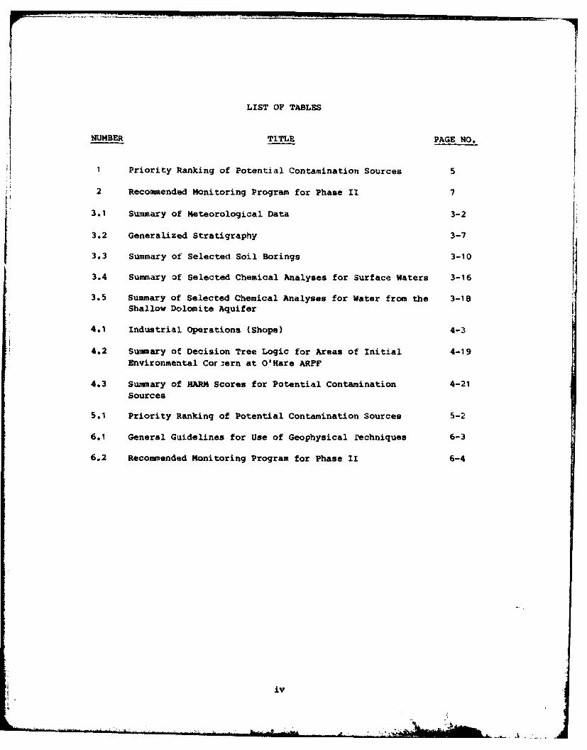
LIST OF TABLES
NUMBER TITLE PAGE NO.
1 Priority Ranking of Potential Contamination Sources 5
2 Recommended Monitoring Program for Phase I 7
3.1 Summary of Meteorological Data 3-2
3.2 Generalized Stratigraphy 3-7
3.3 Summary of Selected Soil Borings 3-10
3.4 Summary of Selected Chemical Analyses for Surface Waters 3-16
3.5 Summary of Selected Chemical Analyses for Water from the 3-18Shallow Dolomite Aquifer
4.1 Industrial Operations (Shops) 4-3
4.2 Summary of Decision Tree Logic for Areas of Initial 4-19Environmental Cor.,ern at O'Hare ARFF
4.3 Summary of HARM Scores for Potential Contamination 4-21Sources
5.1 Priority Ranking of Potential Contamination Sources 5-2
6.1 General Guidelines for Use of Geophysical 'Pechniques 6-3
6.2 Recommended Monitoring Program for Phase II 6-4
iv
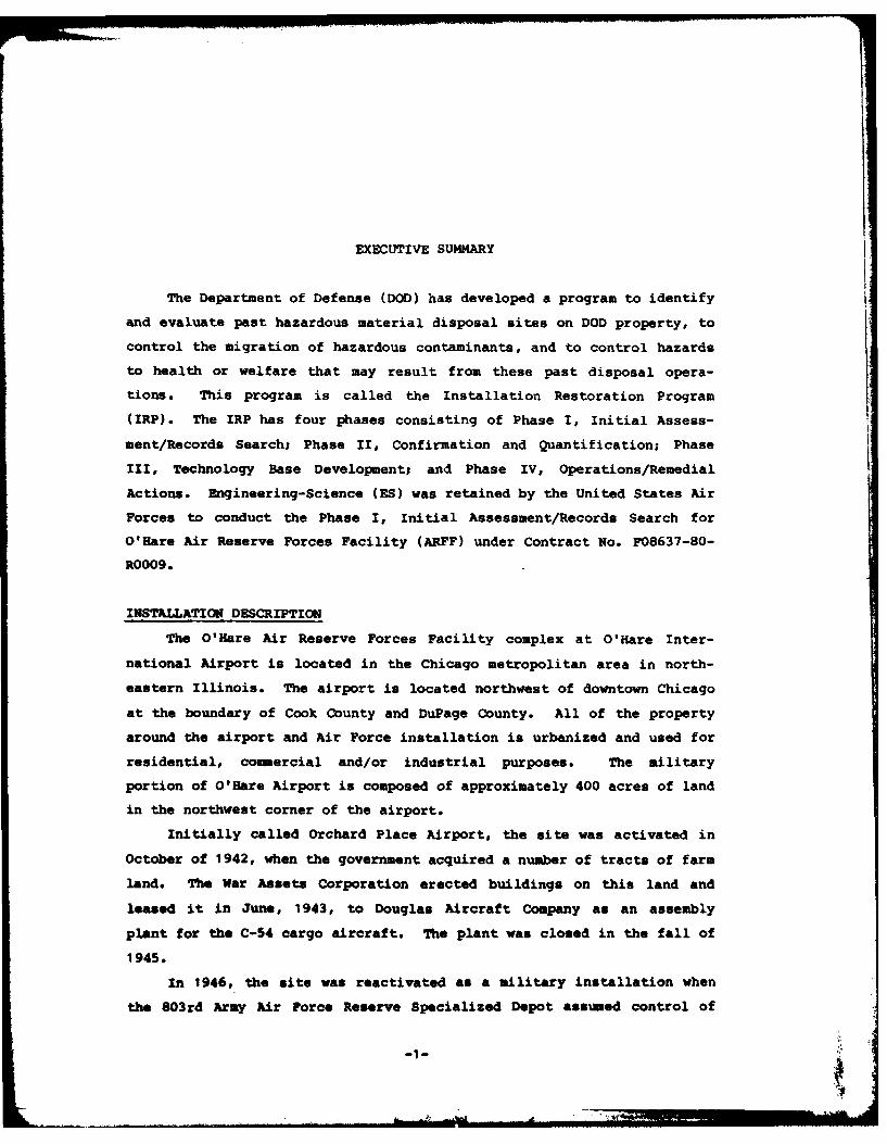
EXECUTIVE SUMMARY
The Department of Defense (DOD) has developed a program to identify
and evaluate past hazardous material disposal sites on DOD property, to
control the migration of hazardous contaminants, and to control hazards
to health or welfare that may result from these past disposal opera-
tions. This program is called the Installation Restoration Program
(IRP). The IRP has four phases consisting of Phase I, Initial Assess-
ment/Records Search; Phase II, Confirmation and Quantification; Phase
III, Technology Base Development; and Phase IV, Operations/Remedial
Actions. Engineering-Science (ES) was retained by the United States Air
Forces to conduct the Phase I, Initial Assessment/Records Search for
O'Hare Air Reserve Forces Facility (ARFF) under Contract No. F08637-80-
R0009.
INSTALLATION DESCRIPTION
The O'Hare Air Reserve Forces Facility complex at O'Hare Inter-
national Airport is located in the Chicago metropolitan area in north-
eastern Illinois. The airport is located northwest of downtown Chicago
at the boundary of Cook County and DuPage County. All of the property
around the airport and Air Force installation is urbanized and used for
residential, commercial and/or industrial purposes. The military
portion of O'Hare Airport is composed of approximately 400 acres of land
in the northwest corner of the airport.
Initially called Orchard Place Airport, the site was activated in
October of 1942, when the government acquired a number of tracts of farm
land. The War Assets Corporation erected buildings on this land and
leased it in June, 1943, to Douglas Aircraft Company as an assembly
plant for the C-54 cargo aircraft. The plant was closed in the fall of
1945.
In 1946, the site was reactivated as a military installation when
the 803rd Army Air Force Reserve Specialized Depot assumed control of
, - , . .... .. . . . .. ...- 1 -
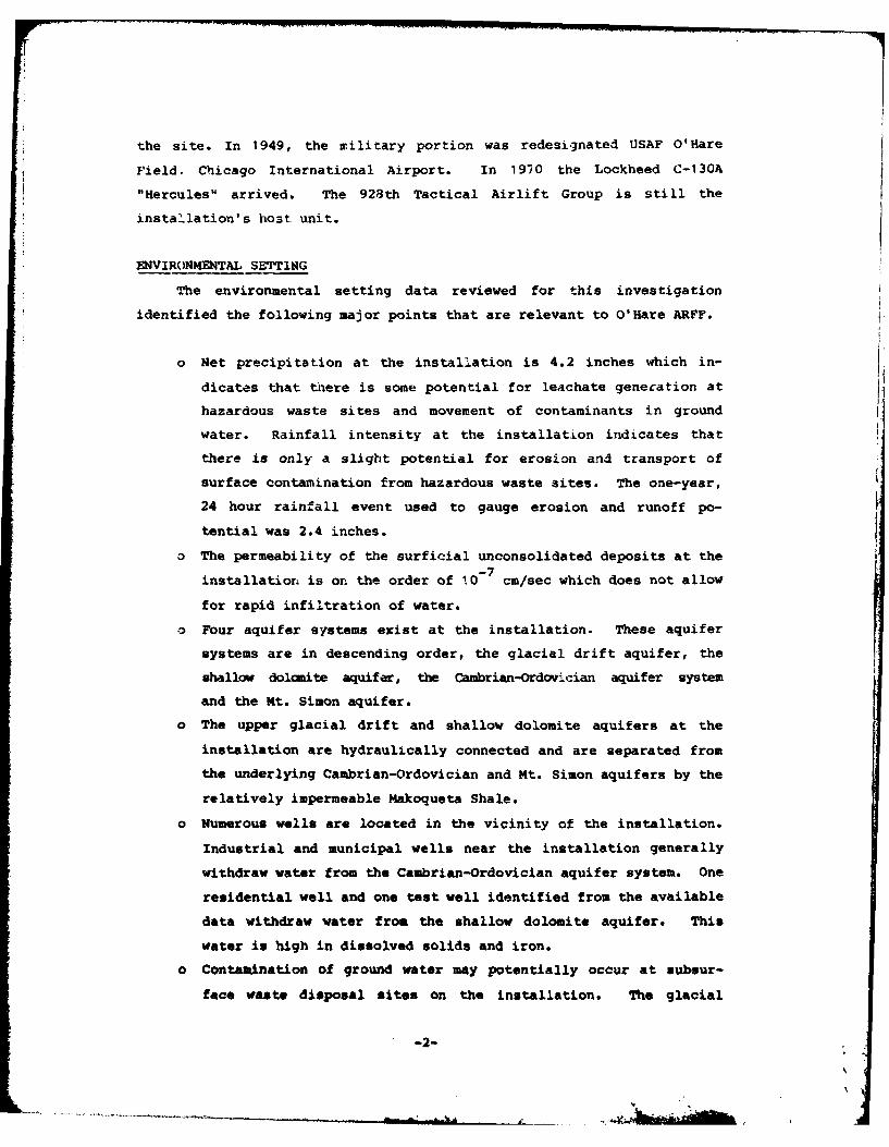
the site. In 1949, the military portion was redesignated USAF O'Hare
Field. Chicago International Airport. In 1910 the Lockheed C-130A
"Hercules" arrived. The 928th Tactical Airlift Group is still the
installation's host unit.
ENVIRONMENTAL SETTING
The environmental setting data reviewed for this investigation
identified the following major points that are relevant to O'Hare ARFF.
o Net precipitation at the installation is 4.2 inches which in-
dicates that there is some potential for leachate generation at
hazardous waste sites and movement of contaminants in ground
water. Rainfall intensity at the installation indicates that
there is only a slight potential for erosion and transport of
surface contamination from hazardous waste sites. The one-year,
24 hour rainfall event used to gauge erosion and runoff po-
tential was 2.4 inches.
o The permeability of the surficial unconsolidated deposits at the
installation is or. the order of 10- 7 cm/sec which does not allow
for rapid infiltration of water.
-D Four aquifer systems exist at the installation. These aquifer
systems are in descending order, the glacial drift aquifer, the
shallow dolomite aquifer, the Cambrian-Ordovician aquifer system
and the Mt. Simon aquifer.
o The upper glacial drift and shallow dolomite aquifers at the
installation are hydraulically connected and are separated from
the underlying Cambrian-Ordovician and Mt. Simon aquifers by the
relatively impermeable Makoqueta Shale.
o Numerous wells are located in the vicinity of the installation.
Industrial and municipal wells near the installation generally
withdraw water from the Cambrian-Ordovician aquifer system. One
residential well and one test well identified from the available
data withdraw water from the shallow dolomite aquifer. This
water is high in dissolved solids and iron.
o Contamination of ground water may potentially occur at subsur-
face waste disposal sites on the installation. The glacial
-2-
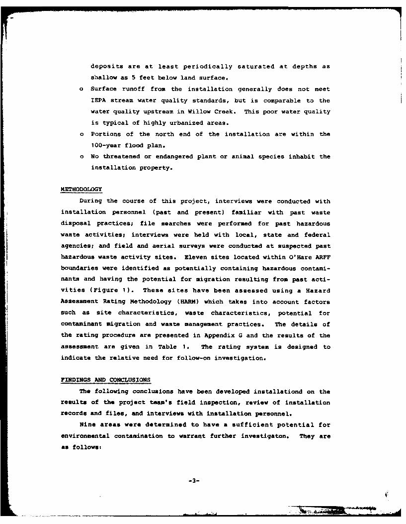
deposits are at least periodically saturated at depths as
shallow as 5 feet below land surface.
o Surface runoff from the installation generally does not meet
IEPA stream water quality standards, but is comparable to the
water quality upstream in Willow Creek. This poor water quality
is typical of highly urbanized areas.
o Portions of the north end of the installation are within the
100-year flood plan.
o No threatened or endangered plant or animal species inhabit the
installation property.
METHODOLOGY
During the course of this project, interviews were conducted with
installation personnel (past and present) familiar with past waste
disposal practices; file searches were performed for past hazardous
waste activities; interviews were held with local, state and federal
agencies; and field and aerial surveys were conducted at suspected past
hazardous waste activity sites. Eleven sites located within O'Hare ARFF
boundaries were identified as potentially containing hazardous contami-
nants and having the potential for migration resulting from past acti-
vities (Figure 1). These sites have been assessed using a Hazard
Assessment Rating Methodology (HARM) which takes into account factors
such as site characteristics, waste characteristics, potential for
contaminant migration and waste management practices. The details of
the rating procedure are presented in Appendix G and the results of the
assessment are given in Table 1. The rating system is designed to
indicate the relative need for follow-on investigation.
FINDINGS AND CONCLUSIONS
The following conclusions have been developed installationd on the
results of the project team's field inspection, review of installation
records and files, and interviews with installation personnel.
Nine areas were determined to have a sufficient potential for
environmental contamination to warrant further investigaton. They are
as follows:
-3-
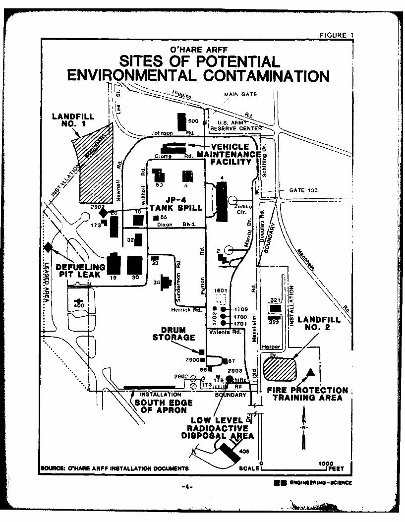
O'HARE ARFF FGR
SITES OF POTENTIALENVIRONMENTAL CONTAMINATION
19 ;."a MAlt. GATE
LANDFILLNO. 1 8- 1:0
ome Rd. MAINTENANCE -
4 cc
CO. K GATE 133
9CTANK SPILL Cmi. d-
17311 Dixon Blvd.>
32180
nI DEFUELINO 0PIT LEAK 19 30 o
1601r or
170 aFIREIL- -INSALLTIO B OAR TRININO. ARE
STRAEACEVDISoSAR
290 600
SOURC.~ O'ARE APF IN TALLATION 8ET WAL'E4 EuETRANGIENG ARCEA~
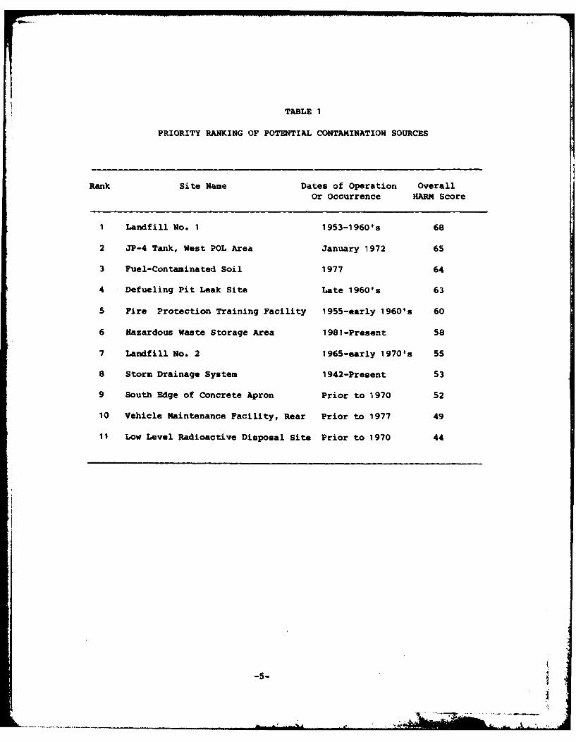
TABLE 1
PRIORITY RANKING OF POTENTIAL CONTAMINATION SOURCES
Rank Site Name Dates of Operation OverallOr Occurrence HARM Score
1 Landfill No. 1 1953-1960's 68
2 JP-4 Tank, West POL Area January 1972 65
3 Fuel-Contaminated Soil 1977 64
4 Defueling Pit Leak Site Late 1960's 63
5 Fire Protection Training Facility 1955-early 1960's 60
6 Hazardous Waste Storage Area 1981-Present 58
7 Landfill No. 2 1965-early 1970's 55
8 Storm Drainage System 1942-Present 53
9 South Edge of Concrete Apron Prior to 1970 52
10 Vehicle Maintenance Facility, Rear Prior to 1977 49
11 Low Level Radioactive Disposal Site Prior to 1970 44
,i -5-
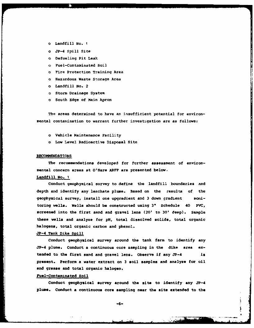
o Landfill No. 1
o JP-4 Spill Site
O Defueling Pit Leak
o Fuel-Contaminated Soil
o Fire Protection Training Area
o Hazardous Waste Storage Area
o Landfill No. 2
o Storm Drainage System
o South Edge of Main Apron
The areas determined to have an insufficient potential for environ-
mental contarination to warrant further investigation are as follows:
o Vehicle Maintenance Facility
o Low Level Radioactive Disposal Site
RECOMMENDATIONS
The recommendations developed for further assessment of environ-
mental concern areas at O'Hare ARFF are presented below.
Landfill No. I
Conduct geophysical survey to define the landfill boundaries and
depth and identify any leachate plume. Based on the results of the
geophysical survey, install one upgradient and 3 down gradient moni-
toring wells. Wells should be constructed using 3" Schedule 40 PVC,
screened into the first sand and gravel lens (20' to 30' deep). Sample
these wells and analyze for pH, total dissolved solids, total organic
halogens, total organic carbon and phenol.
JP-4 Tank Dike Spill
Conduct geophysical survey around the tank farm to identify any
JP-4 plume. Conduct a continuous core sampling in the dike area ex-
tended to the first sand and gravel lens. Observe if any JP-4 is
present. Perform a water extract on 3 soil samples and analyze for oil
and grease and total organic halogen.
Fuel-Contaminated Soil
Conduct geophysical survey around the site to identify any JP-4
plume. Conduct a continuous core sampling near the site extended to the
-6-
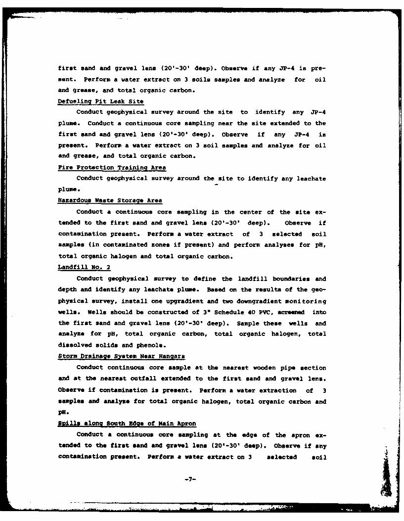
first sand and gravel lens (20'-30' deep). Observe if any JP-4 is pre-
sent. Perform a water extract on 3 soils samples and analyze for oil
and grease, and total organic carbon.
Defueling Pit Leak Site
Conduct geophysical survey around the site to identify any JP-4
plume. Conduct a continuous core sampling near the site extended to the
first sand and gravel lens (20'-30' deep). Observe if any JP-4 is
present. Perform a water extract on 3 soil samples and analyze for oil
and grease, and total organic carbon.
Fire Protection Training Area
Conduct geophysical survey around the site to identify any leachate
plume.
Hazardous Waste Storage Area
Conduct a continuous core sampling in the center of the site ex-
tended to the first sand and gravel lens (201-30' deep). Observe if
contamination present. Perform a water extract of 3 selected soil
samples (in contaminated zones if present) and perform analyses for pH,
total organic halogen and total organic carbon.
Landfill No. 2
Conduct geophysical survey to define the landfill boundaries anddepth and identify any leachate plume. Based on the results of the geo-
physical survey, install one upgradient and two downgradient monitoring
wells. Wells should be constructed of 30 Schedule 40 PVC, screened intothe first sand and gravel lens (20'-301 deep). Sample these wells and
analyze for pH, total organic carbon, total organic halogen, total
dissolved solids and phenols.
Storm Drainage System Near Hangars
Conduct continuous core sample at the nearest wooden pipe section
and at the nearest outfall extended to the first sand and gravel lens.
Observe if contamination is present. Perform a water extraction of 3
samples and analyze for total organic halogen, total organic carbon and
PR.
Spills along South Zdge of Main ApronConduct a continuous core sampling at the edge of the apron ex-
tended to the first sand and gravel lens (20'-30' deep). Observe if any
contamination present. Perform a water extract on 3 selected soil
-7-i
samples (ina contaminated zones if present) and perform analyses for PH1,
total organic halogen and total organic carbon.
SECTION I
INTRODUCTION
BACKGROUND
The United States Air Force, due to its primary mission, has long
been engaged in a wide variety of operations dealing with toxic and
hazardous materials. Federal, state, and local governments have devel-
oped strict regulations to require that disposers identify the locations
and contents of past disposal sites and take action to eliminate hazards
in an environmentally responsible manner. The primary Federal legisla-
tion governing disposal of hazardous waste is the Resource Conservation
and Recovery Act (RCRA) of 1976, as amended. Under Section 6003 of the
Act, Federal agencies are directed to assist the Environmental Protec-
tion Agency (EPA) and under Section 3012, state agencies are required to
inventory past disposal sites and make the information available to the
requesting agencies. To assure compliance with these hazardous waste
regulations, the Department of Defense (DOD) developed the Installation
Restoration Program (IRP). The current DOD IRP policy is contained in
Defense Environmental Quality Program Policy Memorandum (DEQPPM) 81-5,
dated 11 December 1981 and implemented by Air Force message dated 21
January 1982. DEQPPM 81-5 reissued and amplified all previous direc-
tives and memoranda on the Installation Restoration Program. DOD policy
is to identify and fully evaluate suspected problems associated with
past hazardous contamination, and to control hazards to health and wel-
fare that resulted from these past operations. The IRP will be the
basis for response actions on Air Force installations under the provi-
sions of the Comprehensive Environmental Response, Compensation, and
Liability Act (CERCLA) of 1980, and clarified by Executive Order 12316.
1-1 t
PURPOSE AND SCOPE OF THE ASSESS14ENT
The Installation Restoration Program has been developed as a four-
phased program as follows:
Phase I - Initial Assessment/Records Search
Phase II - Confirmation and Quantification
Phase III - Technology installation Development
Phase IV - Operations/Remedial Actions
Engineering-Science (ES) was retained by the United States Air
Force to conduct the Phase I Records Search at O'Hare Air Reserve Forces
Facility (ARFF), Contract No. F08637-80-R0009. This report contains a
summary and an evaluation of the information collected during Phase I of
the IRP and recommendations for follow on actions.
The goal of the first phase of the program was to identify the
potential for environmental contamination from past waste disposal
practices at O'Hare ARFF, and to assess the potential for contaminant
migration. The activities that were performed in the Phase I study
included the following:
- Review of installation records
- Interview of personnel familiar with past generation and dis-
posal activities
- Survey of wastes
- Determination of estimated quantities and locations of current
and past hazardous waste treatment, storage, and disposal
- Definition of the environmental setting at the installation
- Review of past disposal practices and methods
- Field inspection of installation facilities
- Collection of pertinent information from Federal, state and
local agencies
- Assessment of potential for contaminant migration
- Development of follow-on recomendations.
1-2
j ..
ES performed the on-site portion of the records search during
August 1983. The following team of professionals were involved:
- D. L. Gregory, Environmental Engineer and Project Manager, !4SCE,
5 years of professional experience
- H. D. Harmon, Hydrogeologist, 9 years of professional experience
- R. J. Reimer, Chemical Engineer, 4 years of professional experi-
ence
More detailed information on these three individuals is presented in
Appendix A.
METHODOLOGY
The methodology utilized in the O'Hare ARFF Records Search began
with a review of past and present industrial operations conducted at the
installation. Information was obtained from available records and
files, as well as interviews with past and present installation
employees from the various operating areas. Those interviewed included
- current and past personnel associated with Civil Engineering,
Consolidated Aircraft Maintenance, Base Supply, and the Base Clinic. A
listing of the installation interviewees by position and approximate
years of service is presented in Appendix B.
Concurrent with the installation interviews, the applicable
Federal, state and local agencies were contacted for pertinent instal-
lation-related environmental data. The agencies contacted and inter-viewed are listed below and additional information is included in
Appendix B.
o U.S. Environmental Protection Agency (EPA), Region V
o U.S. Geological Survey (USGS), Water Resources Division
o Illinois Environmental Protection Agency
o Illinois Department of Conservation
o Illinois Department of Energy and Natural Resources, State Water
Survey Division
o City of Chicago, Department of Aviation
1-3 1
... . . . . I] Il I I~ ~ l I I J i l l l I
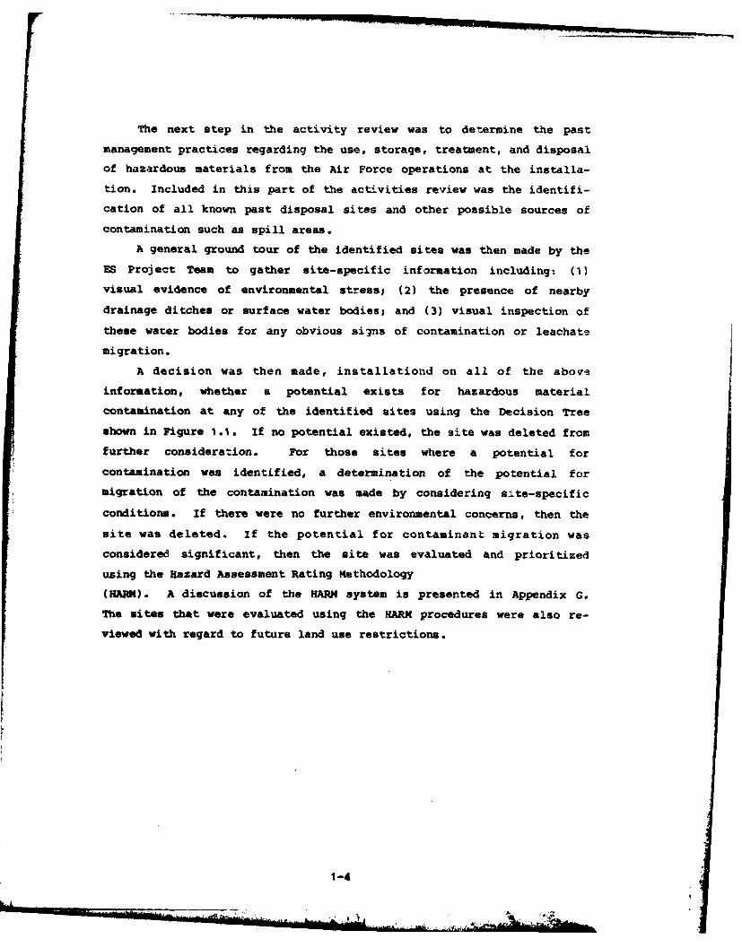
The next step in the activity review was to determine the past
management practices regarding the use, storage, treatment, and disposal
of hazardous materials from the Air Force operations at the installa-
tion. Included in this part of the activities review was the identifi-
cation of all known past disposal sites and other possible sources of
contamination such as spill areas.
A general ground tour of the identified sites was then made by the
ES Project Team to gather site-specific information including: (1)
visual evidence of environmental stress; (2) the presence of nearby
drainage ditches or surface water bodies; and (3) visual inspection of
these water bodies for any obvious signs of contamination or leachate
migration.
A decision was then made, installationd on all of the above
information, whether a potential exists for hazardous material
contamination at any of the identified sites using the Decision Tree
shown in Figure 1 .1. if no potential existed, the site was deleted from
further consideration. For those sites where a potential for
contamination was identified, a determination of the potential for
migration of the contamination was made by considering site-specific
conditions. If there were no further environmental concerns, then the
site was deleted. If the potential for contaminant migration was
considered significant, then the site was evaluated and prioritized
using the Hazard Assessment Rating Methodology
(HARM). A discussion of the HARM system is presented in Appendix G.
The sites that were evaluated using the HARM procedures were also re-
viewed with regard to future land use restrictions.
1-4
.
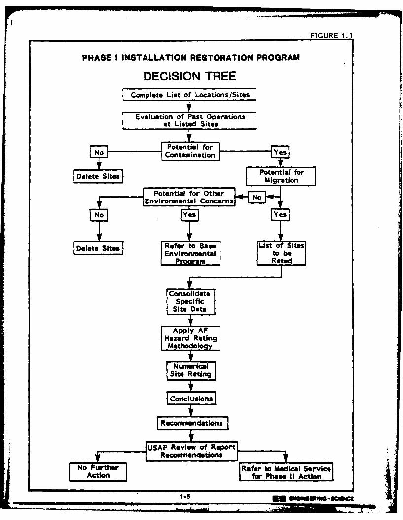
FIGURE 1. 1
PHASE I INSTALLATION RESTORATION PROGRAM
DECISION TREELComplete List of Locations/Sites
Evaluation of Past Operationsat Listed Sites
Delete Sites Refr o as
C~vionetlsioncrs]
Recomendtion
UAEvinenta of Reer
r -
SECTION 2
INSTALLATION DESCRIPTION
LOCATION, SIZE AND BOUNDARIES
O'Hare Air Reserve Forces Facility at O'Hare International Airport
is located in the Chicago metropolitan area in northeastern Illinois
(Figures 2.1 and 2.2). The airport is located northwest of downtown
Chicago at the boundary of Cook County and DuPage County. All of the
property around the airport and Air Force installation is urbanized and
used for residential, commercial and/or industrial purposes. The
military portion of O'Hare Airport is composed of approximately 400
acres of land in the northeast corner of the airport. The Air Force
also leases a portion of the southeast taxiway. The Air Force has
retained the priority use of all runways. Figure 2.3 depicts the
configuration of the installation property.
INSTALLATION HISTORY
Initially called Orchard Place Airport, the site was activated in
October of 1942, when the government acquired a number of tracts of farm
land. The War Assets Corporation erected buildings on this land to be
used for an aircraft assembly plant.
In June of 1943, the installation was leased to Douglas Aircraft
Company as an assembly plant for the C-54 cargo aircraft. The site was
known as the "Chicago Aircraft Assembly Plant Number 8." During the
years of 1943 to 1945, approximately 665 aircraft were assembled and
delivered to the Army Air Corps. The plant was then closed in the fall
of 1945.
In 1946, the site was reactivated as a military installation when
the 803rd Army Air Force Reserve Specialized Depot assumed control of
the site. During this time, the 141st Air Force installation unit for
reserve training was activated at the renamed Douglas-Orchard Airport.
In 1948, the 141st was replaced by the 2471st AF Reserve Combat
Training Center. In 1949, both the 437th and the 441st Troop Carrier
2-1
i--'7
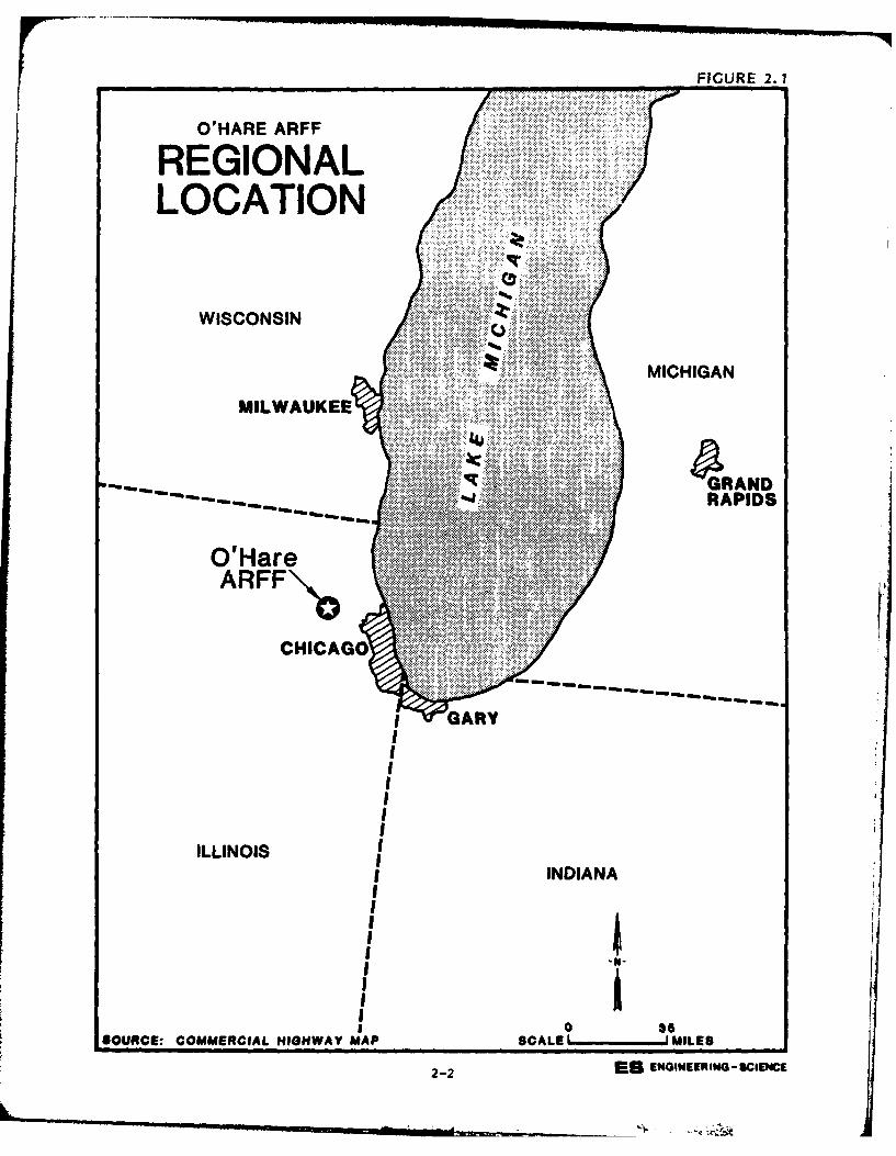
F FIGURE 2.1
O'HARE ARFF
REGIONALLOCATION
WISCONSIN
MICHIGAN
MILWAUKEE
GqRANDRAPIDS
O'HareARFF\.L,
CHICAGO
GARY
ILLINOIININ
I3-SOUCE:COMERCIL HGHWY MA SCLE ILE
2-ISEGNERN CEC
LI
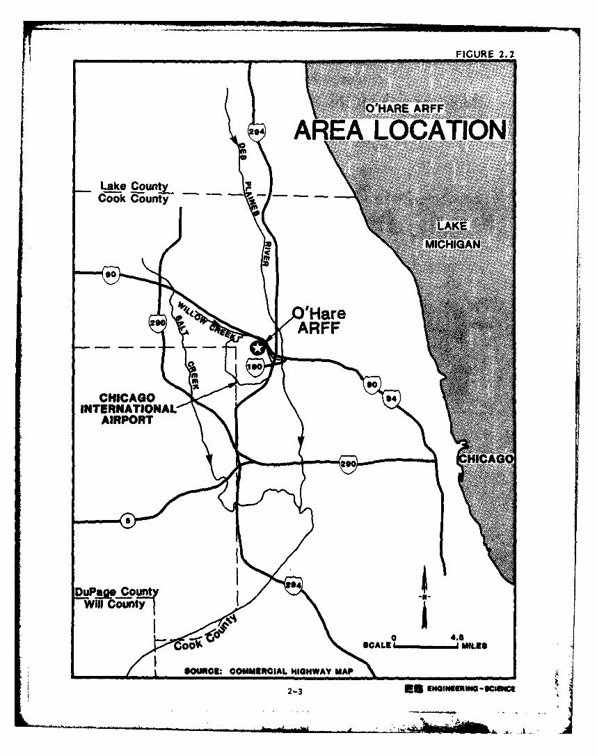
FIGURE 2.2
.......... ..
Lake County ~..'~Cook County- Ni.~ . .
. . . . .. . . . .. . . . .. . . . .. ..
0... ..... ...
INTERNATIONAL ~
AIRPORT
SOUCE: COMMERCIAL HIGHWAY MAP
2-3 * NI~RW~~c
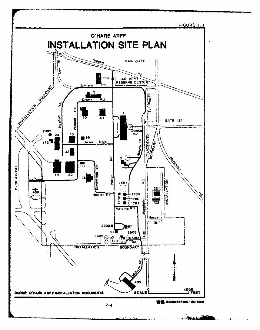
FIGURE 2.3
OlIARE ARFF
INSTALLATION SITE PLANOf& MAIN GATE
I:0 J.AR
RESERVE CENTEV
50
0)0
so15
013232
itI 1Ha or35r -]9
z170000
OUNCE ~ ~ ~ ~ ~ 0r-7 OMi 322F zNTLAINDCMNSSAEFE
Va- nt Rd. INIECnSUc
Wings Reserve were activated. In 1949, the military portion was re-
designated USAF O'Hare Field, Chicago International Airport.
From October 1950 until December 1957, the 2471st AFRCTC remained
the supervisory unit. In 1955, the airfields were opened to commercial
traffic.
From May 1957 until October 1970, the 928th Tactical Airlift Group
was equipped with the Fairchild C-119 "Flying Boxcar", and in 1970 the
Lockheed C-130A "Herculesm arrived. The 928th TAG is still the in-
stallation's host unit.
ORGANIZATION AND MISSION
O'Hare ARFF at O'Hare International Airport has a fulltime staff of
1,544 employees. For one weekend per month and two full weeks per year,
the installation serves as a training facility for approximately 2400
Air Force Reservists and Air National Guardsmen.
The host organization at O'Hare ARFF is the 928th Tactical Airlift
Group (TAG). The primary mission of the 928th TAG is to provide
individual and unit training in the C-130A, tactical airlift support for
airborne forces, equipment, supplies and aeromedical evacuation within a
theater of operations. Additionally, the Group operates and maintains
the Air Force complex at O'Hare, represents the Air Force in the Chicago
metropolitan area, and provides logistical support to various on/off
installation tenants.
The on-installation tenants at the O'Hare ARFF are listed below.
Descriptions of the major tenant and other installation organizations
and their missions are presented in Appendix C.
o Defense Contract Administration Services Region
o Defense Logistics Agency
o Headquarters, Illinois Air National Guard (Ill ANG)
o 126th Air Refueling Wing, Ill ANG
o 126th Combat Support Group, Ill ANG
o 108th Air Refueling Squadron, Ill ANG
o 126th Consolidated Aircraft Maintenance Squadron, Ill ANG
o .126th USAF Clinic, Ill ANG
o !26th Civil Engineering Flight, Ill ANG
2-5
_ _ _ _ _ _ _ _ _ _2~5 I
o 126th Communications Flight, Ill AUG
o 217th Electronics installation Squadron, Ill ANG
o 264th Communications Squadron, Ill AUG
o 566th USAF Band, Ill ANG
o UISAF Liaison office/National Scouting Organization
o 36th Medical Service Evacuation Squadron
o Aeronautical Systems Divi:.ion, Reserve Detachment (AFLC)
o Corps of Engineers Field Office
2-6
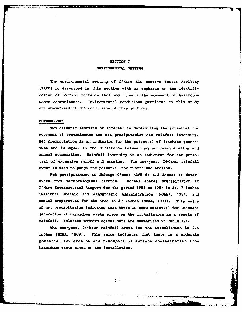
SECTION 3
ENVIRONMENTAL SETTING
The environmental setting of O'Hare Air Reserve Forces Facility
(ARFF) is described in this section with an emphasis on the identifi-
cation of natural features that may promote the movement of hazardous
waste contaminants. Environmental conditions pertinent to this study
are summarized at the conclusion of this section.
METEOROLOGY
Two climatic features of interest in determining the potential for
movement of contaminants are net precipitation and rainfall intensity.
Net precipitation is an indicator for the potential of leachate genera-
tion and is equal to the difference between annual precipitation and
annual evaporation. Rainfall intensity is an indicator for the poten-
tial of excessive runoff and erosion. The one-year, 24-hour rainfall
event is used to gauge the potential for runoff and erosion.
Net precipitation at Chicago O'Hare ARFF is 4.2 inches as deter-
mined from meteorological records. Normal annual precipitation at
O'Hare International Airport for the period 1958 to 1981 is 34.17 inches
(National Oceanic and Atmospheric Administration (NOAA), 1981) and
annual evaporation for the area is 30 inches (NOAA, 1977). This value
of net precipitation indicates that there is some potential for leachate
generation at hazardous waste sites on the installation as a result of
rainfall. Selected meteorological data are summarized in Table 3.1.
The one-year, 24-hour rainfall event for the installation is 2.4
inches (NOAA, 1968). This value indicates that there is a moderate
potential for erosion and transport of surface contamination from
hazardous waste sites on the installation.
3-1
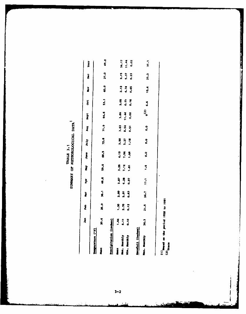
q -, C
C ,l . f1.a in f1 kno
VD - CdlN 0 0S
c ono
EZ Al 00l
an 50 -4
U,;
14P J.
3-2
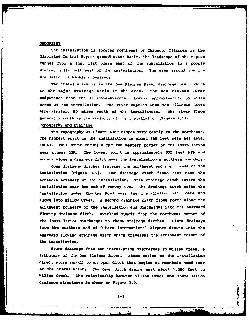
GEOGRAPHY
The installation is located northwest of Chicago, Illinois in the
Glaciated Central Region ground-water basin. The landscape of the region
ranges from a low, flat plain east of the installation to a poorly
drained hilly belt west of the installation. The area around the in-
stallation is highly urbanized.
The installation is in the Des Plaines River drainage basin which
is the major drainage basin in the area. The Des Plaines River
originates near the Illinois-Wisconsin border approximately 30 miles
north of the installation. The river empties into the Illinois River
approximately 50 miles south of the installation. The river flows
generally south in the vicinity of the installation (Figure 3.1).
Topography and Drainage
The topography at O'Hare ARFF slopes very gently to the northeast.
The highest point on the installation is about 650 feet mean sea level
(D4SL). This point occurs along the western border of the installation
near runway 22R. The lowest point is approximately 635 feet ISL and
occurs along a drainage ditch near the installation's northern boundary.
Open drainage ditches traverse the northwest and north ends of the
installation (Figure 3.2). One drainage ditch flows east near the
northern boundary of the installation. This drainage ditch enters the
installation near the end of runway 22R. The drainage ditch exits the
installation under Higgins Road near the installation main gate and
flows into Willow Creek. A second drainage ditch flows north along the
northwest boundary of the installation and discharges into the eastward
flowing drainage ditch. Overland runoff from the northwest corner of
the installation discharges to these drainage ditches. Storm drainage
from the northern end of O'Hare International Airport drains into the
eastward flowing drainage ditch which traverses the northwest corner of
the installation.
Storm drainage from the installation discharges to Willow Creek, a
tributary of the Des Plaines River. Storm drains on the installation
direct storm runoff to an open ditch that begins at Mannheim Road east
of the installation. The open ditch drains east about 1,300 feet to
Willow Creek. The relationship between Willow Creek and installation
drainage structures is shown on Figure 3,2.
3-3
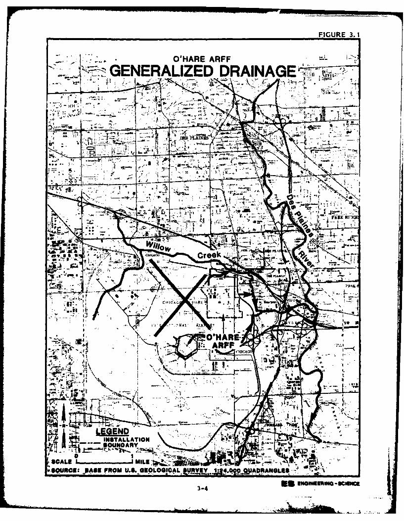
FIGURE 3. 1
O'HARE ARFF.
SGENERALIZED DRAINAGE',',
'44
A' G
BOUNDARY-
3-4 m
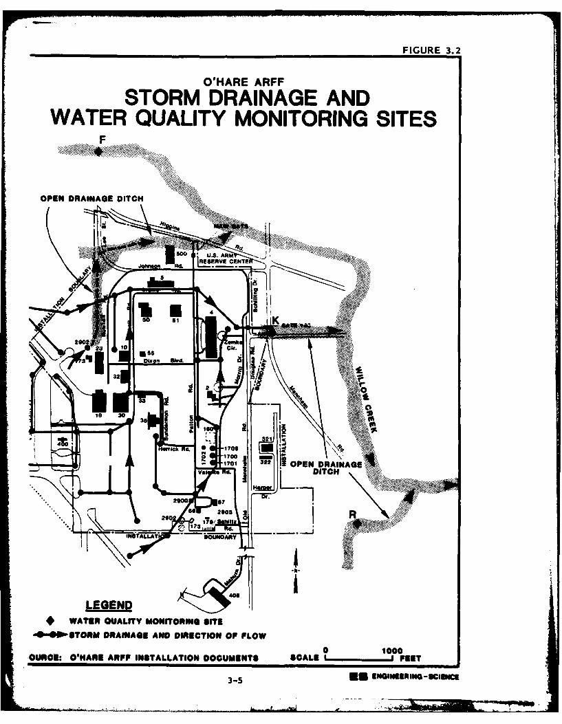
FIGURE 3.2
O'HARE ARFF
STORM DRAINAGE ANDWATER QUALITY MONITORING SITES
OPEN DRAINAGE DITC
Soo.... .... .:..
REEV ENTE
400
10 0 .... ... .
3232I
35 ~ ~ 10 -.
- 701 OPEN DRAIN0AGE ,.,.va a 1141.DITCH
290 7*.
OURCI O'HRE APPOISTALATO 111DCMNT CLEFE
35* NIEEIGU"c
GEOLOGY
Stratigraphy
O'Hare ARFF is underlain by rocks of Precambrian age and younger
and unconsolidated glacial deposits. A stratigraphic column represent-
ing the sequence of rocks in the area is given in Table 3.2.
Dense crystalline rock of Precambrian age forms the installation-
ment upon which younger geologic units were deposited. The depth below
land surface to these rocks is probably greater than 4,000 feet at the
installation. The only well in the Chicago area known to penetrate the
Precambrian was drilled approximately 6 miles west of Joliet, Illinois.
(Bradbury and Atherton, 1965).
A l.yered sequence of gently eastward dipping sedinentary rocks of
Cambrian and Ordovician age overlie the Precambrian rocks. These rocks
are mainly sandstone and dolomite and are probably greater than 3,000
feet thick at the installation. (Hughes and others, 1966). The
Ordovician age rocks have a combined thickness of about 800 feet in the
vicinity of the installation.
Silurian age dolomite overlies the Ordovician rocks and is the
upper bedrock unit at the installation. This unit is mostly dense
dolomite with many joints and solution channels. It's thickness is
about 135 feet in the vicinity of the installation.
The thickness of the Ordovician and Silurian rocks were derived
from a drilling log for a well that was drilled for the Twin Orchard
Country Club prior to the existence of the airport. This well was
drilled in 1925 to a total depth of 1,410 feet. The approximate well
location is shown on Figure 3.3.
Unconsolidated glacial deposits of Quaternary age overlie the
bedrock to a thickness of 70 to 85 feet at the installation (Figure
3.4). These deposits consist of stratified clay, sand and gravel. The
deposits appear to thicken toward the north end of the installation.
The surficial deposits at the installation are mostly artificial
fill underlain by clay. The composition of unconsolidated deposits near
the surface is described in Table 3.3.
3-6
A...a- , a.J L .fm
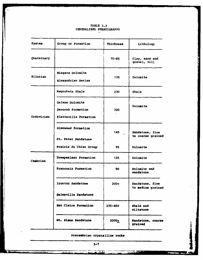
TABLE 3.2
GENERALIZED STRATIGRAPHY
System Group or Formation Thickness Lithology
Quaternary 70-85 Clay, sand andgravel, till
Niagara DolomiteSilurian 135 Dolomite
Alexandrian Series
Maquoketa Shale 230 Shale
Galena DolomiteDolomite
Decorah Formation 320
Ordovician Platteville Formation
Glenwood Formation145 Sandstone, fine
to coarse grainedSt. Peter Sandstone
Prairie du Chien Group 95 Dolomite
Trempealeau Formation 125 DolomiteCambrian
Franconia Formation 90 Dolomite andsandstone
Ironton Sandstone 200+ Sandstone, fineto medium grained
Galesville Sandstone
Eau Claire Formation 235-450 Shale andsiltstone
Mt. Simon Sandstone 2000+ Sandstone, coarsegrained
Precambrian crystalline rocks
307
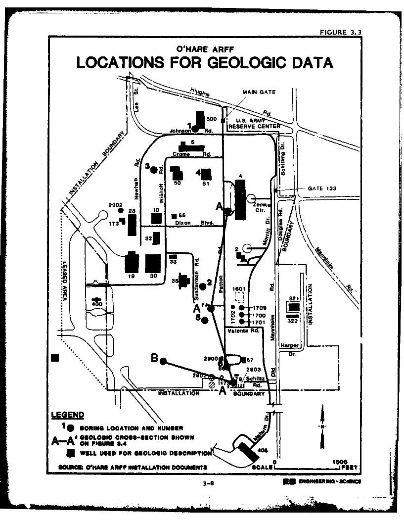
FIGURE 3.3
O'HARE ARFF
LOCATIONS FOR GEOLOGIC DATA
MAIN GATE
50 LUS ARM
'~Rd. jERVE CENTE
Ui -so 51____50 GA TE 133
2902 sink23 1 Cir. -d
* 32* m 2
* 4*
.9"19 30
*~36E 2 *
:m 321J1
* C0-1700
q-01701
ValentaRd
U Rd.INTA-LLATION -A-ON
LEGEND10BORINO LOCATION AND NUMBER111
Am=AD ::,0L,,0 C,0ROSS*-SECTION "mowN"N WELL U9SE1 FOR GEOLOGIC DESCRIPTION 0lop00
S0S0IC WHARM AP ISTALLATION DOCUNINT SCALE 11 FEET
3-S U
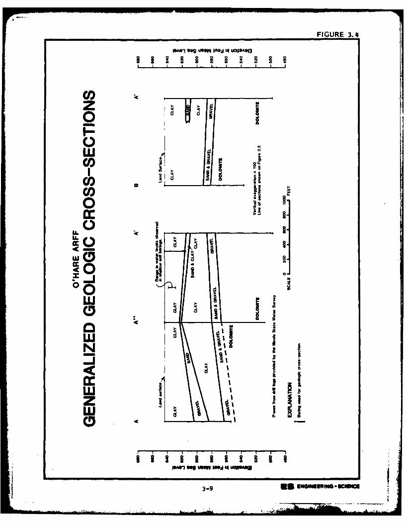
1602 L4UDOR013FIGURE 3.4
0
LU ?co)UI
Cl)CO)0
m0
-ml
zi 9
03-9
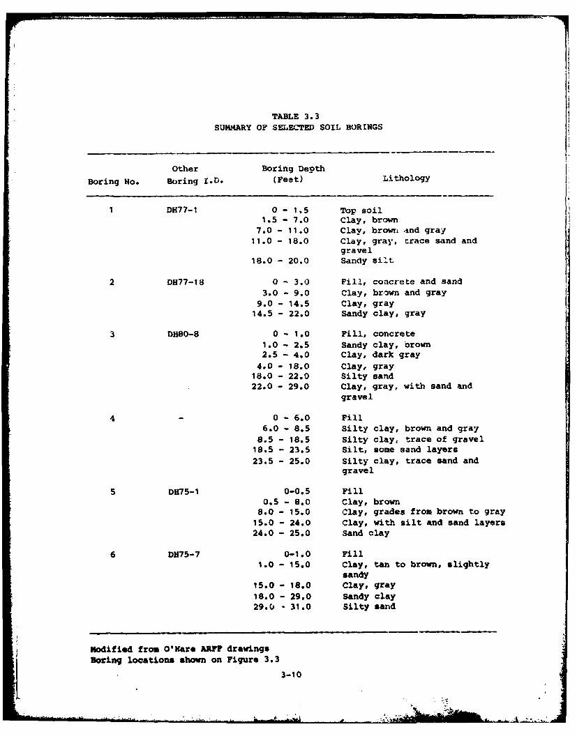
TABLE 3.3SUMMARY OF SELECTED SOIL BORINGS
Other Boring Depth
Boring No. Boring I.D. (Feet) Lithology
DH77-1 0 - 1.5 Top soil1.5 - 7.0 Clay, brown
7.0 - 11.0 Clay, brown tnd gray11.0 - 18.0 Clay, gray, trace sand and
gravel18.0 - 20.0 Sandy silt
2 DH77-18 0 - 3.0 Fill, concrete and sand3.0 - 9.0 Clay, br-wn and gray
9.0 - 14.5 Clay, gray14.5 - 22.0 Sandy clay, gray
3 DH80-8 0 - 1.0 Fill, concrete1.0 - 2.5 Sandy clay, brown2.5 - 4.0 Clay, dark gray
4.0 - 18.0 Clay, gray18.0 - 22.0 Silty sand22.0 - 29.0 Clay, gray, with sand and
gravel
40 - 6.0 Fill6.0 - 8.5 Silty clay, brown and gray8.5 - 18.5 Silty clay, trace of gravel18.5 - 23.5 Silt, some sand layers23.5 - 25.0 Silty clay, trace sand and
gravel
5 DH75-I 0-0.5 Fill0.5 - 8.0 Clay, brown
8.0 - 15.0 Clay, grades from brown to gray15.0 - 24.0 Clay, with silt and sand layers24.0 - 25.0 Sand clay
6 DH75-7 0-1.0 Fill1.0 - 15.0 Clay, tan to brown, slightly
sandy15.0 - 18.0 Clay, gray
18.0 - 29.0 Sandy clay29.0 - 31.0 Silty sand
Modified from O'Hare ARFF drawingsBoring locations shown on Figure 3.3L 3-10
Structure
The Chicago area is located near the crest of a broad, gently
sloping arch composed mostly of Cambrian, Ordovician and Silurian rocks.
The longitudinal axis of this arch runs generally in a northwest-south-
east direction. The rocks have a general eastward dip that results from
the eastward plunge of the arch.
The major structural feature near the installation is the Des
Plaines Disturbance. Rocks in the area of the Disturbance are intensely
faulted. The origin of the faulting is unknown but has been speculated
to have been caused by a meteorite impact (Willman, 1971). The area ofthe Des Plaines Disturbance is approximately five-miles square. The
southern end of the Disturbance is located approximately one-mile north
of. the installation.
HYDROLOGY
Subsurface Hydrology
There are four major aquifer systems in the vicinity of O'Hare
ARFF. These aquifer systems are sand and gravel deposits of the glacial
drift, shallow dolomites composed mostly of Silurian age rocks, the Cam-
brian-Ordovician aquifer system and the Mt. Simon aquifer. The glacial
drift and shallow dolomite aquifers are separated from the underlying
deeper aquifers by the Maquoketa Shale.
The glacial drift and shallow dolomite are of greatest interest for
this study. These are the uppermost geologic units at the installation.
The glacial drift and shallow dolomite are both recharged locally
from precipitation and are hydrologically connected in the Chicago area
(Suter, 1959). The hydrologic connection is generally good whenever
sand and gravel directly overlies the dolomite. This situation exists
at O'Hare ARFF (Figure 3.4).
The glacial drift in the vicinity of the installation has an
average vertical hydraulic conductivity, or permeability, on the ord-r
of 0.005 gallons per day per square f ct (2.4 x 10 centimeters persecond). This estimate assumes that recharge through the drift averages
140,000 gallons per day per square mile and that recharge is occurring
3-11
under a unit hydraulic gradient. These assumptioib appear reasonable
based on work done by Walton (1965) in DuPage county that is immediately
west of the installation. This permeability estimate indicates that
percolation to the water table of the installation is low.
Ground-water elevations and ground-water flow directions in the
shallow dolomite are not known at the ins-alla'ion. Water levels in
borings completed in the shallow dolomite on the installation stood at
an elevation of 625 to 630 feet mean sea level in 1942. This water
level was 15 to 20 feet below land surface. Water levels in the shallow
dolomite were generally greater than 50 feet below land surface in
DuPage County west of the installation in 1965 (Walton, 1965).
The unconsolidated deposits are saturated in part at the instal-
lation (Figure 3.4). Water levels nave been observed 5 to 15 feet
below land surface in shallow soil borings drilled on the installation
between 1975 and 1980 for foundation investigations.
There is a potential for contamination of ground water to occur at
subsurface waste disposal sites on the installation. The glacial de-
posits are at least periodically saturated at depths of 5 feet and more
below land surface. Waste material buried to depths of 5 feet or more
would be periodically saturated and could create leachate. Also, there
would be a tendency for the leachate to move downward to the shallow,
dolomite aquifer.
Surface Hydroly
O'Hare ARFF is in the Willow Creek drainage basin. The installa-
tion is drained by a combination of open channels and drainage struc-
tures that discharge to the creek (Figure 3.2). The main stem of Willow
Creek does not traverse the installation.
Periodic flooding can be expected at the north end of the installa-
tion. These floodwaters originate mostly as runoff from O'Hare Inter-
national Airport and from the urbanized area west and north of the
airport. The approximate limits of flooding for the 100-year flood
event are shown on Figure 3.5.
3-12
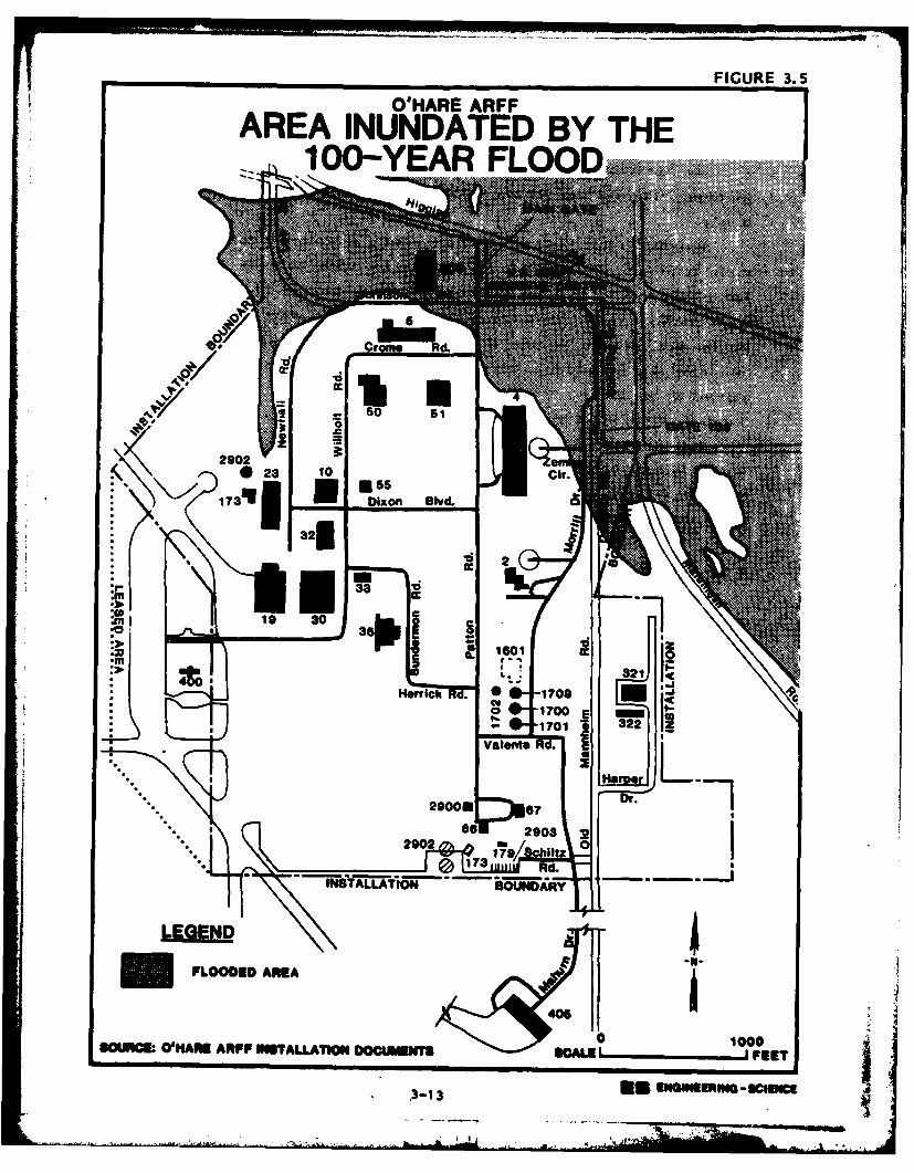
FIGURE 3.5
O'HARE ARFFAREA INUNDATED BY THE100-YEAR FLOOD~
50 51 ' .. ~
-.PLOOEDARE
0 U R200 C a A h A P S T L A I W O O U E T F E
2-3 10 if
055.1~
WATE USE
The installation receives its water supply from the City of
Chicago. Surface and ground waters are not used for installation
supply.
Numerous industrial and municipal supply wells are located in the
vicinity of the installation. Most wells are 1,000 to 2,000 feet deep
and withdraw water from the Cambrian-Ordovician aquifer system. A few
wells withdraw water from the shallow dolomite aquifer system. The
approximate location of the wells that could be identified from theavailable data are shown on Figure 3.6. (Six water supply wells are not
plotted on the figure; insufficient data were available to determine the
location of the wells within the section.)
Some residential wells exist in the vicinity of the installation
(R. T. Sasnan, Illinois State Water Survey, oral communication, 1983).
The closest well completed in the shallow dolomite is located approxi-
mately one and one-half miles east of the installation.
WAE WUALITYSurface water quality is monitored in the Willow Creek watershed by
personnel employed by the airport facility. (Landrum and Brown, 1983).
The parameters monitored include biochemical oxygen demand (DOD), pH,suspended solids, total dissolved solids, fats, oil and grease, dis-
solved oxygen and hexane solubles. The locations of the monitoring
sites (F, K and R) in the vicinity of the instailation are shown on
Figure 3.2 and the monitoring results for the period November 1981 to
October 1982 are summarized in Table 3.4. Runoff from the installation
is monitored at site K.
The results of water quality monitoring indicates that water dis-
charging to the creek from the installation does not meet all WPDES/-Illinois Environmental Protection Agency (12PA) standards. (Lendrum andBrown, 1983). Suspended solids in the water generally exceeded stan-
dards and fats, oil and grease in the water have exceeded standards.
Water quality parameters in other surface waters nearby also exceed
IZPA standards (Table 3.4). Discharge standards are generally exceeded
in Willow Creek at site F above the confluence with the installation
drainage ditch and at site R in a drainage ditch that discharges to
3-14
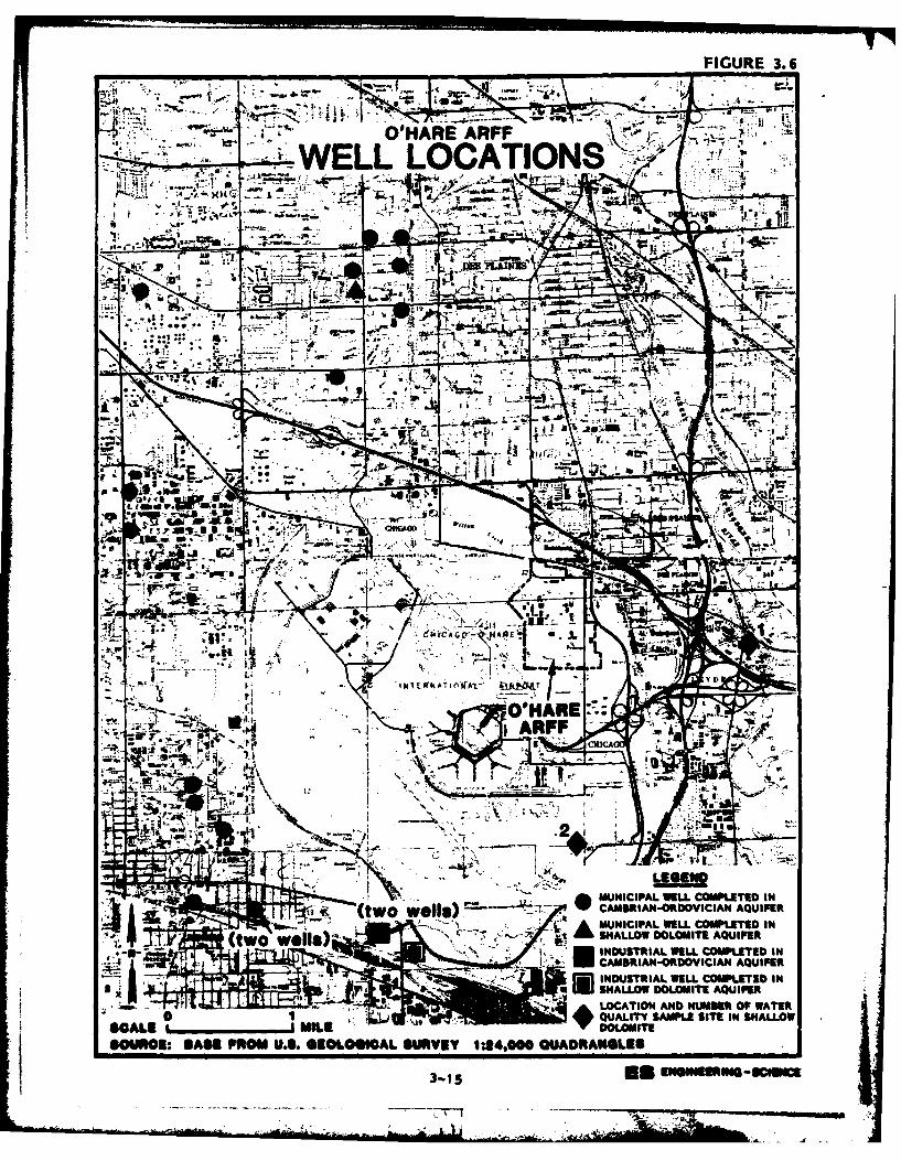
FIGURE 3.6
"00 k 1,J 1A
WHARE ARFFA-1
ova,
WELL LOCATI NsPI-ilk
I-~ jj: m I7 7f s
V- 1IA 2-
OL
-A,-am-
.- :7 IN.
low;M
Glle" A
,004
crit
TVTV
30 34i A
"A
ICE-7 1A
'O'k G Cr 01 E'
I h 7 E 104 A T I 0)fkt- vv
OPHARE::-XK ARFF
00 CMCA
*41;tL -17
.2
........ MUNICIPAL WELL COMPLETED IN-(two Well*) CAMMIAN-ORDOVICIAN AQUIFER4LI IT-*1MUNICIPAL WELL COMPLETED IN
(two wells)- SNALLOW DOLOMITE AQUIFERi, INDUSTRIAL WELL COMPLETED IN
CAMBRIAN-ORDOVICIAN AQUIFERINDUSTRIAL WELL COMPLETED INSNALLOW DOLOMITE AQUIFER
Hilt LOCATION AND NUMBER OF WATER0 A Alf QUALITY SAMPLE SITE IN SNALLOW
SCALE -j m a DOLOMITESOURCE: BASE FROM U.S. 41109 041CA1 VRT 1:24,000 imel as
3 11 5
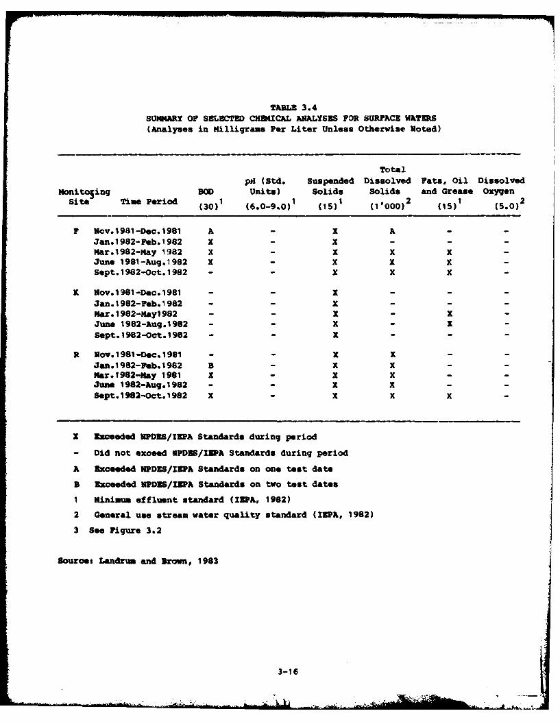
TABLE 3.4SUMMARY OF SELECTED CHUSICAL ANALYSES FOR SURFACE WATERS(Analyses in Milligrams Per Liter Unlearn Otherwise Noted)
Totalpal (Std. Suspended Dissolved Fats, Oil Dissolved
Monitosing BOD Units) Solids Solids and Grease Oxygen
sie Tm eid (30) 1 (6.0-9.0)1 (15) 1 (11000) 2 (15) (5.0)2
F Uov.1981-Dec.19831 A - X A --
Jan.1982-Feb.1982 x - X---M4ar.1982-M4ay 1982 X - X X X-June 1981-Aug.1982 X - X X X-Sept.1982-Oct.1982 - - X X X-
K Mov.1981-Dec.1981 - - X ---
Jan.1982-Feb.1982 - - X ---
Har. I982-14ayl 982 - - X - XJune 1982-Aug.1982 - - X - X
Sept.1982-Oct.1982 - - X - - -
R Uov.1981-Dec.1981 - - X X - -
Jan.1982-Peb.1982 B - X X - -
M~ar.1982-Nay 1981 X - X X - -
June 1982-Aug.1982 - - X X - -
Sept.1982-Oct.1982 X - X X X -
X Exceeded VPD3S/IEPA Standards during period
- Did not exceed 6PDES/IBPA. Standards during period
A Exceeded VPDES/IhPA Standards on one test date
B Exceeded UPDES/IEPA Standards on two test dates
1 Minimum effluent standard (IEPA, 1982)
2 General use stream water quality standard (IEPA, 1982)
3 See Figure 3.2
Sourcet Landrum and Brown, 1983
3-16
Willow Creek downstream from the installation drainage ditch. Poor
water quality is typical of highly urbanized areas.
Water quality data for the shallow dolomite aquifer (Table 3.5) are
available at two locations near the installation (Figure 3.6). One
location is a
residential supply well located approximately 1.5 miles east of the in-
stallation. The other location is a test well located approximately 1.5
miles south of the installation.
Water from the shallow dolomite is high in dissolved minerals
(Table 3.5). The total dissolved solids content in the water is above
recommended limits for public water supplies (USEPA, 1975). The iron
content of the water is near the recommended upper limit.
The shallow dolomite well east of the installation (Figure 3.6,Well No. 1) shows signs of contamination. The chloride and sulfate
contents in the water appear high and surfactants were detected in the
water. Surfactants do not occur naturally in water. The contamination
could result from any number of sources.
BIOTIC DIVIRONMDRT
O'Hare ARFF has limited habitat available for wildlife. The in-
stallation consists mainly of cultivated lawns, building sites, and
paved areas which offer negligible shelter for animals. Small tracts of
unmowed brush and grass provide forage and cover for small mamals and
birds. There are no threatened or endangered plant or animal species
inhabiting the installation property. Four endangered animal speciesare known to inhabit the region (within 50 miles) and may occasionally
visit the installation or airport. These are the Indiana bat, peregrine
falcon, upland sandpiper, and marsh hawk. There is no indication that
past installation activities have disrupted the patterns of these
species.
SUMMY O MVIRMNIK TAL STING
The environmental setting data reviewed for this investigation
identified the following major points that are relevant to O'Hare AR.
o Net precipitation at the installation is 4.2 inches which in-
dicates that there is some potential for leachate generation at
3-17 All AM
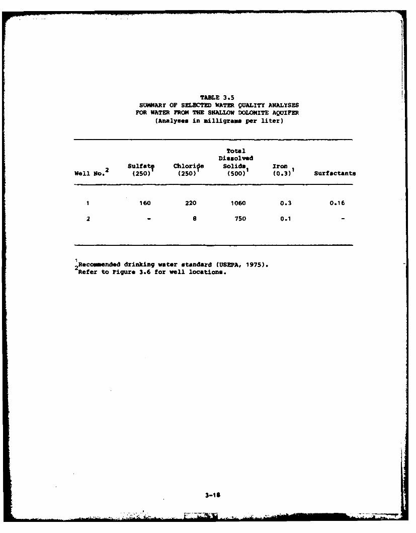
TABLE 3.5SUMMARf OF SELECTED WATER QUALITY ANALYSESFOR WATER FROM4 THE SHALLOW DOLOMITE AQUIFER
(Analyses in milligrams per liter)
TotalDissolved
2 Sulfat? Chlorife Solids1 IronWell No. (250) (250) (500) (0.3) Surfactants
1 160 220 1060 0.3 0.16
2 -8 750 0.1
Recommended drinking water standard (USEPA, 1975).2 Refer to Figure 3.6 for well locations.
3-18
L Mkj. Ibi."
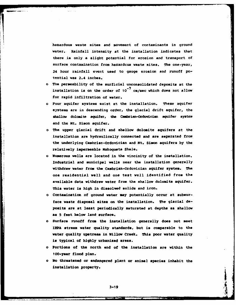
hazardous waste sites and movement of contaminants in ground
water. Rainfall intensity at the installation indicates that
there is only a slight potential for erosion and transport of
surface contamination from hazardcus waste sites. The one-year,
24 hour rainfall event used to gauge erosion and runoff po-
tential was 2.4 inches.
o The permeability of the surficial unconsolidated deposits at the
installation is on the order of 10- 7 cm/sec which does not allow
for rapid infiltration of water.
o Four aquifer systems exist at the installation. These aquifer
systems are in descending order, the glacial drift aquifer, the
shallow dolomite aquifer, the Cambrian-Ordovician aquifer system
and the Mt. Simon aquifer.
o The upper glacial drift and shallow dolomite aquifers at the
installation are hydraulically connected and are separated fromthe underlying Cambrian-Ordovician and Mt. Simon aquifers by the
relatively impermeable Makoqueta Shale.
o Numerous wells are located in the vincinity of the installation.
Industrial and municipal wells near the installation generally
withdraw water from the Cambrian-Ordovician aquifer system. The
one residential well and one test well identified from the
available data withdraw water from the shallow dolomite aquifer.
This water is high in dissolved solids and iron.
o Contamination of ground water may potentially occur at subsur-
face waste disposal sites on the installation. The glacial de-
posits are at least periodically saturated at depths as shallow
as 5 feet below land surface.
o Surface runoff from the installation generally does not meet
IEPA stream water quality standards, but is comparable to the
water quality upstream in Willow Creek. This poor water quality
is typical of highly urbanized areas.
o Portions of the north end of the installation are within the
100-year flood plan.
o No threatened or endangered plant or animal species inhabit the
installation property. '4
3-19
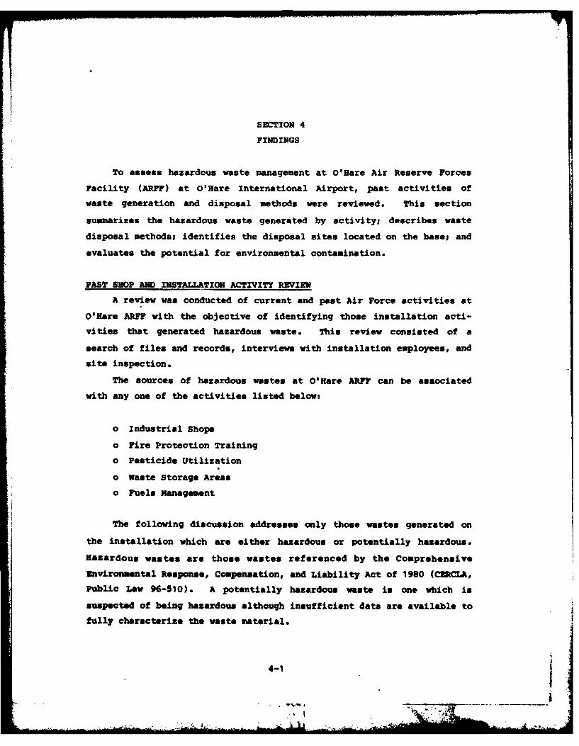
SECTION 4
FINDINGS
To assess hazardous waste management at O'Hare Air Reserve Forces
Facility (ARFF) at O'Hare International Airport, past activities of
waste generation and disposal methods were reviewed. This section
summarizes the hazardous waste generated by activity; describes waste
disposal methods; identifies the disposal sites located on the base; and
evaluates the potential for environmental contamination.
PAST SHOP AND INSTALLATION ACTIVITY REVIEW
A review was conducted of current and past Air Force activities at
O'Hare ARFF with the objective of identifying those installation acti-vities that generated hazardous waste. This review consisted of a
search of files and records, interviews with installation employees, and
site inspection.
The sources of hazardous wastes at O'Hare ARFF can be associated
with any one of the activities listed below:
o Industrial Shops
o Fire Protection Training
o Pesticide Utilization
o Waste Storage Areas
o Fuels Management
The following discussion addresses only those wastes generated on
the installation which are either hazardous or potentially hazardous.
Hazardous wastes are those wastes referenced by the Comprehensive
Environmental Response, Compensation, and Liability Act of 1980 (CUCLA,
Public Law 96-510), A potentially hazardous waste is one which is
suspected of being hazardous although insufficient data are available to
fully characterize the waste material.
4-1
I
INDUSTRIhL OPERATIONS (SHOPS)
Since the O'Hare ARFF opened in 1946, the main function of the
industrial operations (shops) or the installation has been to provide
maintenance support activities to aircraft flying missions. Activities
have included aircraft equipment maintenance, ground equipment main-
tenance, and installation facilities maintenance. A list of present
industrial shops was obtained from the installation clinic files.
Information contained in the files indicates if the shops handle
hazardous materials and generate hazardous waste. A summary of the
pertinent information from the shop files is presented in Appendix E,
Master List of Industrial Shops.
For the shops known to generate hazardous wastes, interviews with
personnel familiar with shop activities were conducted. The information
obtained from interviews and installation records has been summarized in
Table 4.1. For each generator of hazardous wastes, this table presents
the shop location, waste materials generated, quantities of wastes gene-
rated, and a disposal method timeline. Many of the disposal methods
were identified from information obtained from past and present person-
nel of O'Hare ARFF. The waste quantities shown in Table 4.1 are based
on verbal estimates given by present shop personnel at the time of the
interviews. The shops that have generated insignificant quantities or
no hazardous waste are not listed in Table 4.1.
From 1943 to 1945 the area that is now O'Hare ARFF was a govern-
ment-owned, contractor-operated plant (Douglas Aircraft Assembly Plant
No. 8). Assembly operations typically do not generate significant
amounts of hazardous solid waste. Most of the hazardous waste generated
resulted from the painting operations. Several underground tanks stored
paint thinners and fuels. All but one of these tanks (a fuel tank) have
since been excavated and removed. Paper and other office materials were
burned in an incinerator. Other wastes generated by this operation were
disposed of in a manner that is not well defined. There are no records
of any landfilling or other disposal operations during this period of
time.
In the early years of installation operations, (1946 to 1955), an
off-aite cantractor collected cacstible liquid wastes (primarily mate
oil) and removed them from the installation. From approximately 1955 to
4-2
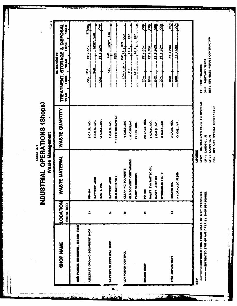
04 4it JddU0 Wj ITIi II I
pq ILI
on zI I~
-i I . z go, I I I I I 1 1 1ii Ii r
81 t 1t , I I I I I 1$ 0 1UIIIII I I I lII I II iL
z
-C a
Go 0
me in-a 4 j ~ --i
0 UU A 15 "
0; 2S in~ .
I-r U. U.
W 0i_ _ _ _ 3zI
__ __ __ _ __ _ _ _ _ _ _ _ _ _ _ _ w
.--.----.------.------ j .- -- -
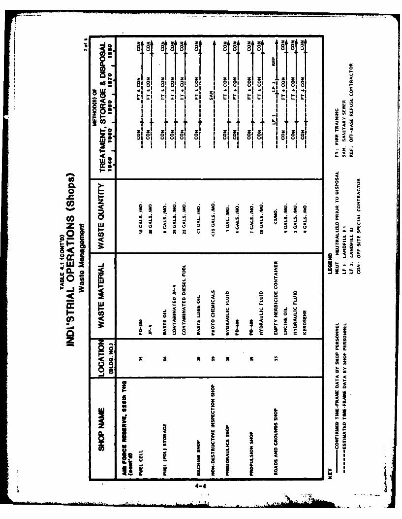
-Iz zA zzh z z z a IZOT T I I I I ILITI 1 0
W 6 . L6 L
0101 331 ~ 40I0I0ii ululu
wU
I -C
00zz zz I I I I
U. 0 l cc
CL - 40
Lu V0 t 3 < -
1. 0
W W 00 ul 4A 40LI .
LI IL U1 L
g~ OA '00 v A m
z zw
3 00
U3 za. 0
a-UU
i A9L -UIL II z u
3! £0 1Wa x ml
_ _ _ _ _ _ _ _ _ _ _ _ _ _ _ _ _ _ _ _ _ _ _ _ _ _ _ _ _ _ _ _ _ _ _ _ _ _ _ _ _ _
- 4-4
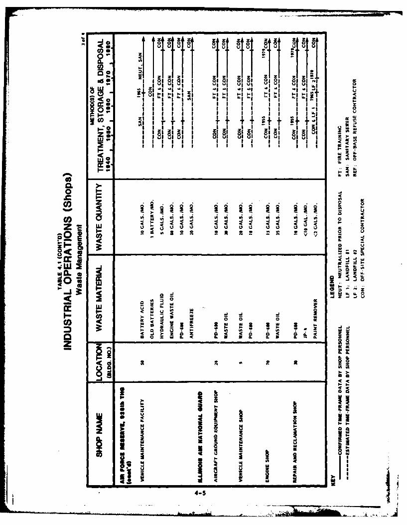
40* 1A A azi Z ' z Z
(I lululu u ulul ulul uu ui i
0 L-oi Z- -IZz z i
I- uI fi £010
0 1
Colz 0
<l IA Il I A A U S VI U J UI r r it R
c Uw0 Z 0.
z-J
U. 4A
WW u
as u0 CL
CL ww Z ZI-
o. JC 01 0 0-
#A. 0. 31 -. U30-bLA uj LU22
I-I- I-j____A__'A__________usmz a 04 -C -Z* o 0 mL -Ca t IL 9
'aLin
vi Z-
IL 4
-4-
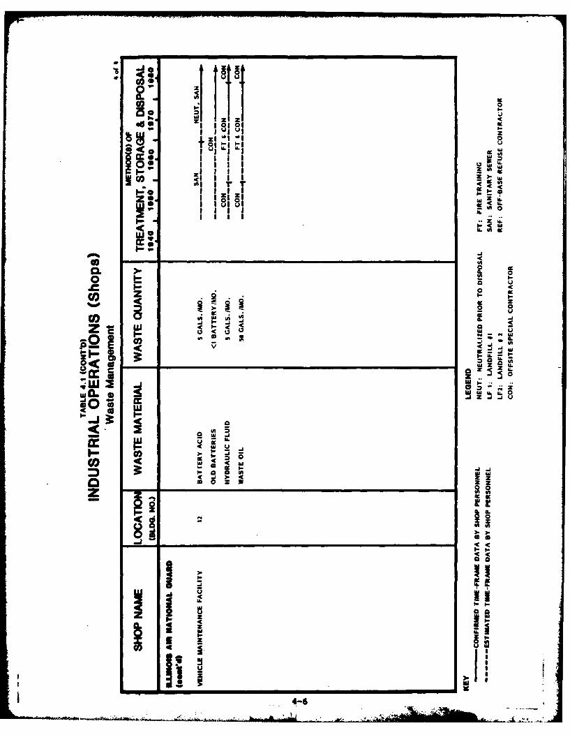
A z z 4
uus
z IIImIl z
I~~ 155LUl lulu
IHII09
I-c
co Ko o
uja -
In30
wA Z w
U j
.( 0 an
C4-
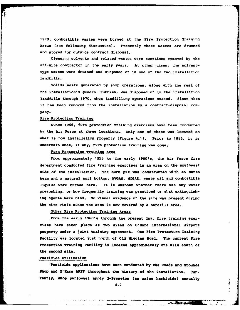
1979, combustible wastes were burned at the Fire Protection Training
Areas (see following discussion). Presently these wastes are drummed
and stored for outside contract disposal.
Cleaning solvents and related wastes were sometimes removed by the
off-site contractor in the early years. At other times, the solvent-
type wastes were drummed and disposed of in one of the two installation
landfills.
Solids waste generated by shop operations, along with the rest of
the installation's general rubbish, was disposed of in the installation
landfills through 1970, when landfilling operations ceased. Since then
it has been removed from the installation by a contract-disposal com-
pany.
Fire Protection Training
Since 1955, fire protection training exercises have been conducted
by the Air Force at three locations. Only one of these was located on
what is now installation property (Figure 4.1). Prior to 1955, it is
uncertain what, if any, fire protection training was done.
Fire Protection Training Area
From approximately 1955 to the early 1960's, the Air Force fire
department conducted fire training exercises in an area on the southeast
side of the installation. The burn pit was constructed with an earth
berm and a natural soil bottom. AVGAS, IOGAS, waste oil and combustible
liquids were burned here. It is unknown whether there was any water
presoaking, or how frequently training was practiced or what extinguish-
ing agents were used. No visual evidence of the site was present during
the site visit since the area is now covered by a hardfill area.
Other Fire Protection Training Areas
From the early 1960's through the present day, fire training exer-
cises have taken place at two sites on O'Hare International Airport
property under a joint training agreement. One Fire Protection Training
Facility was located just north of Old Higgins Road. The current Fire
Protection Training Facility is located approximately one mile south of
the second site.
Pesticide Utilization
Pesticide applications have been conducted by the Roads and Grounds
Shop and O'Hare ARFF throughout the history of the installation. Cur-
rently, shop personnel apply 2-Prometon (an amine herbicide) annually
4-7
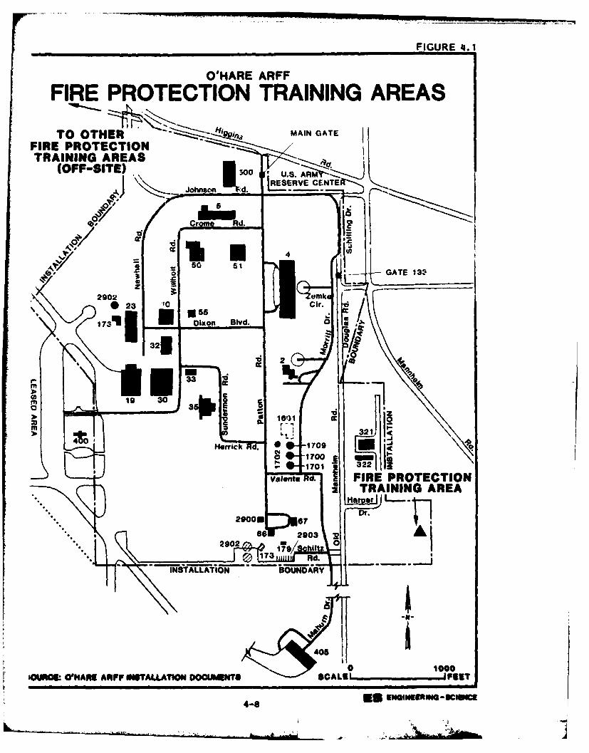
FIGURE 4i.1
O'HARE ARFF
FIRE PROTECTION TRAINING AREAS
TO OTHER MAIN GATE
FIRE PROTECTIONTRAINING AREAS
(OFF-SITE) 1300 .8 R
RES ~.ERVE CENTE
A.0onsn d
4/V.
GAT 11330
23 0 i. -
22
m
350
0 100
'OUN0U.~~velnt Rd.AR FIRE PROTECTIONCUENS CAE''P
48 US TRANING AEA3

throughout the installation for general weed control. ll of the pesti-
cide material prepared is used up in the application process. No other
pesticides or herbicides were reported as being used. Containers are
rinsed and disposed of as general refuse.
Waste Storage Areas
Presently, waste chemicals and used oils at O'Hare ARFF are accumu-
lated at the site of generation until removed to a central storage area.
This storage area is located in a depressed area at the south end of the
Old Assembly Plant foundation, a former truck loading area (Figure 4.2).
The area is open to the weather and access is not controlled. The soil
in this storage area was darker than normal, indicating that past spills
had occurred.
Drums of waste from the hangers are accumulated on an outside con-
crete wash rack area adjacent to the buildings (Figure 4.2). The area
is located over a drain grill that discharges to either the surface
drainage system or the sanitary sewer system. During aircraft washing
operations, the drain is directed to the sanitary sewer via a nearby,
underground oil/water separator. Otherwise, the drain feeds the storm
sewer system. The discharge direction is selected by moving a vane
located underneath the grill. The concrete is stained indicating that
spills and/or leaks have occurred.
Fuels Management
The O'Hare ARFF Fuels Management storage system consists of fifteen
above ground and below ground tanks in two areas (west POL and south POL
areas). A listing of the locations of the fuel storage tanks and their
contents and capacities has been provided in Appendix D. Fuels stored
at O'Hare ARFF include: JP-4, MOGAS, FS-5 and FS-2 (No. 2 Fuel Oil).
Fuels are currently delivered to the installation by tank truck. In the
past, fuel has been delivered to the west and south POL areas by railcar
as well.
JP-4 is stored in the west POL storage area in one above ground
210,000 gallon tank and two under ground 50,000 gallon tanks. The
aboveground tank is equipped with secondary containment in the form of
an earth dike over an asphaltic material. The diked areas are checked
daily, with water acomulations discharged to the surface drainage
system. A hydrant network was previously used to fuel aircraft on the
.,-9-1v
I-- !
)k .A
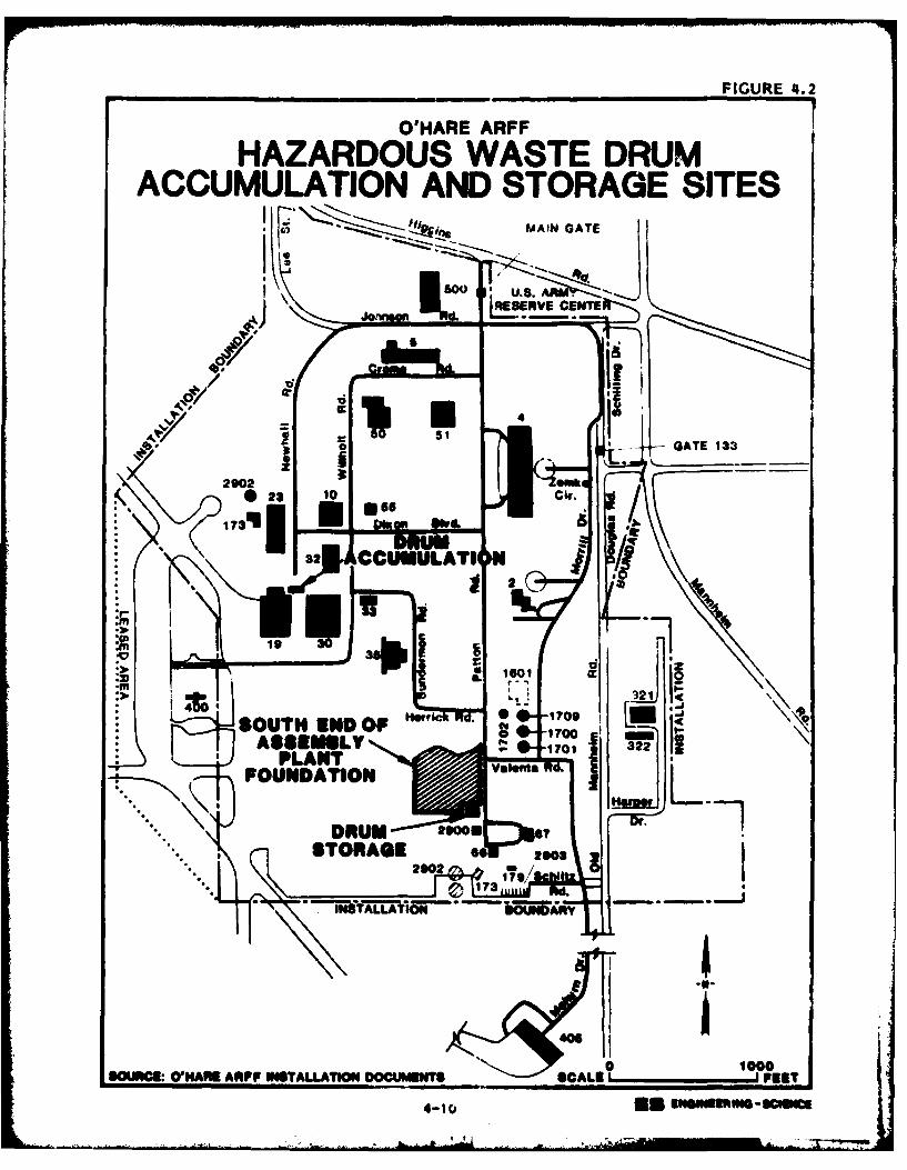
FIGURE 4.2
O'HARE ARFFHAZARDOUS WASTE DRUM
ACCUMULATION AND STORAGE SITESMAIN GATE
151
STOGATE o3
0 230000OURCL~~ ~ w aRA P W T L A~O O U Ns P
173'US Dia"DOM
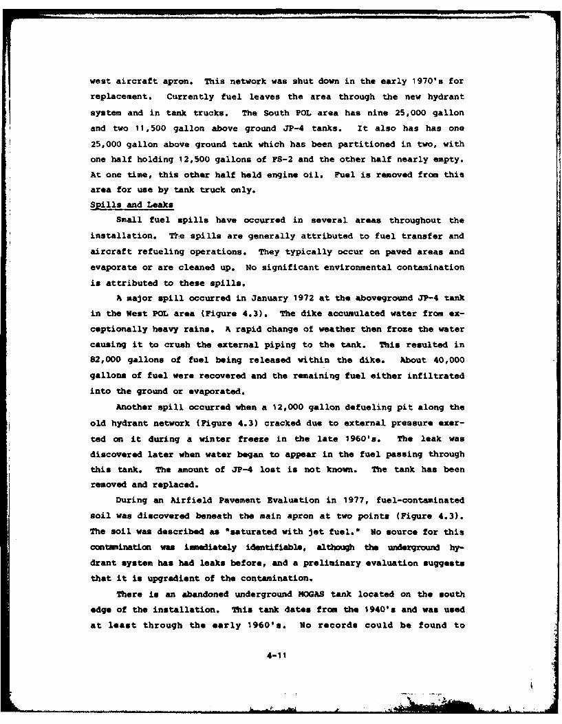
west aircraft apron. This network was shut down in the early 1970's for
replacement. Currently fuel leaves the area through the new hydrant
system and in tank trucks. The South POL area has nine 25,000 gallon
and two 11,500 gallon above ground JP-4 tanks. It also has has one
25,000 gallon above ground tank which has been partitioned in two, with
one half holding 12,500 gallons of FS-2 and the other half nearly empty.
At one time, this other half held engine oil. Fuel is removed from this
area for use by tank truck only.
Spills and Leaks
Small fuel spills have occurred in several areas throughout the
installation. The spills are generally attributed to fuel transfer and
aircraft refueling operations. They typically occur on paved areas and
evaporate or are cleaned up. No significant environmental contamination
is attributed to these spills.
A major spill occurred in January 1972 at the aboveground JP-4 tank
in the West POL area (Figure 4.3). The dike accumulated water from ex-
ceptionally heavy rains. A rapid change of weather then froze the water
causing it to crush the external piping to the tank. This resulted in
82,000 gallons of fuel being released within the dike. About 40,000
gallons of fuel were recovered and the remaining fuel either infiltrated
into the ground or evaporated.
Another spill occurred when a 12,000 gallon defueling pit along the
old hydrant network (Figure 4.3) cracked due to external pressure exer-
ted on it during a winter freeze in the late 1960's. The leak was
discovered later when water began to appear in the fuel passing through
this tank. The amount of JP-4 lost is not known. The tank has been
removed and replaced.
During an Airfield Pavement Evaluation in 1977, fuel-contaminatedsoil was discovered beneath the main apron at two points (Figure 4.3).
The soil was described as "saturated with jet fuel." No source for this
nimmnation was immediately identifiable, although the underground hy-
drant system has had leaks before, and a preliminary evaluation suggests
that it is upgradient of the contamination.
There is an abandoned underground NOGAS tank located on the south
edge of the installation. This tank dates from the 1940's and was used
at least through the early 1960's. No records could be found to
4-11
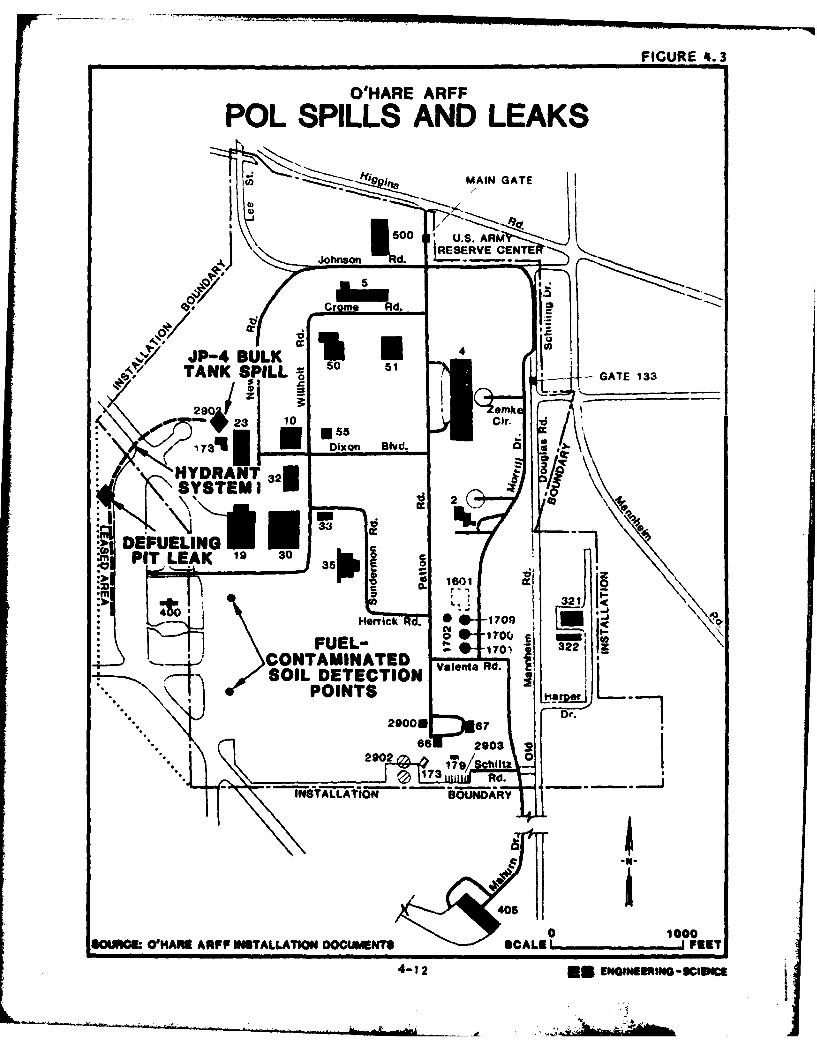
FIGURE 4. 3
ODHARE ARFF
POL SPILLS AND LEAKS.~ 91. MAIN GATE
0 SARM
TANK~5 LEUSELL C 0 GTE13
160
gDr
231000
SOURCE, OIAR A S A L ON DO UM NT SC LEr' EE
173 2io Blvd ENIfrX03I~
describe the tank, and no information regarding tank closure could be
established.
A ground disposal site at the Vehicle Maintenance Facility (Bldg.
5) (Figure 4.4) was reported to be the location for regular dumping of
motor oil until the mid 1970's. No evidence of this action was observed
during the site visit since the area behind the building has been cover-
ed over by a concrete vehicle parking lot. The contaminated soil may
have been removed during construction of the parking lot.
During the 1950's and 1960's the area south of the south apron was
used as an occasional dumping area for small quantities of liquid wastes
from the shops (Figure 4.4). The material would flow into a storm water
drainage ditch which ran parallel to the edge about ten feet away and be
washed away from the site. Due to the irregular frequency and small
quantity of dupings, this area was not listed as a "disposal method" in
Table 4.1, Industrial Operations. No evidence of environmental stress
could be found here during the site visit.
DESCRIPTION OF PAST ON-INSTALLATION DISPOSAL METHODS
The facilities at O'Hare ARFF which have been used for the manage-
ment and disposal of waste can be categorized as follows:
o Landfills
o Hardfills
o Storm Drainage System
o Sanitary Sewer System
o Low Level Radioactive Disposal Area
Landfills
Two landfill operations were identified at O'Hare ARFF. These two
landfills are discussed below.
Landfill go. 1 (1953-1965)
Landfill No. 1 was operated from 1953-1965. It was located on the
northwest side of the installation, along Newhall/Lee Street and Higgins
(Figure 4.5). During the early operation, trash was filled in a slight-
ly depressed area. Trench and fill operations became the standard
operating procedure after a few years. The trenches were excavated
4-13
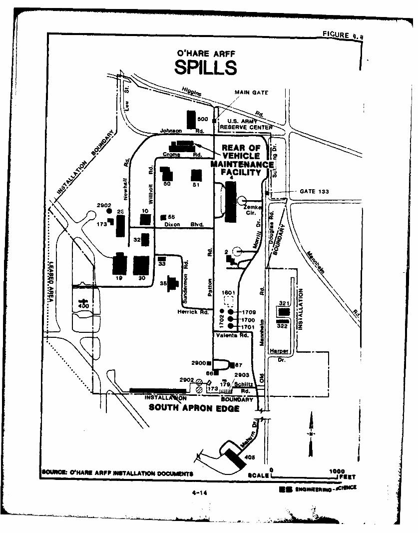
FIGURE .
O'HARE ARF
SPILLS
REAR OF '
Coe EHCL
BOUTNA
2S 101000
3213Id 2
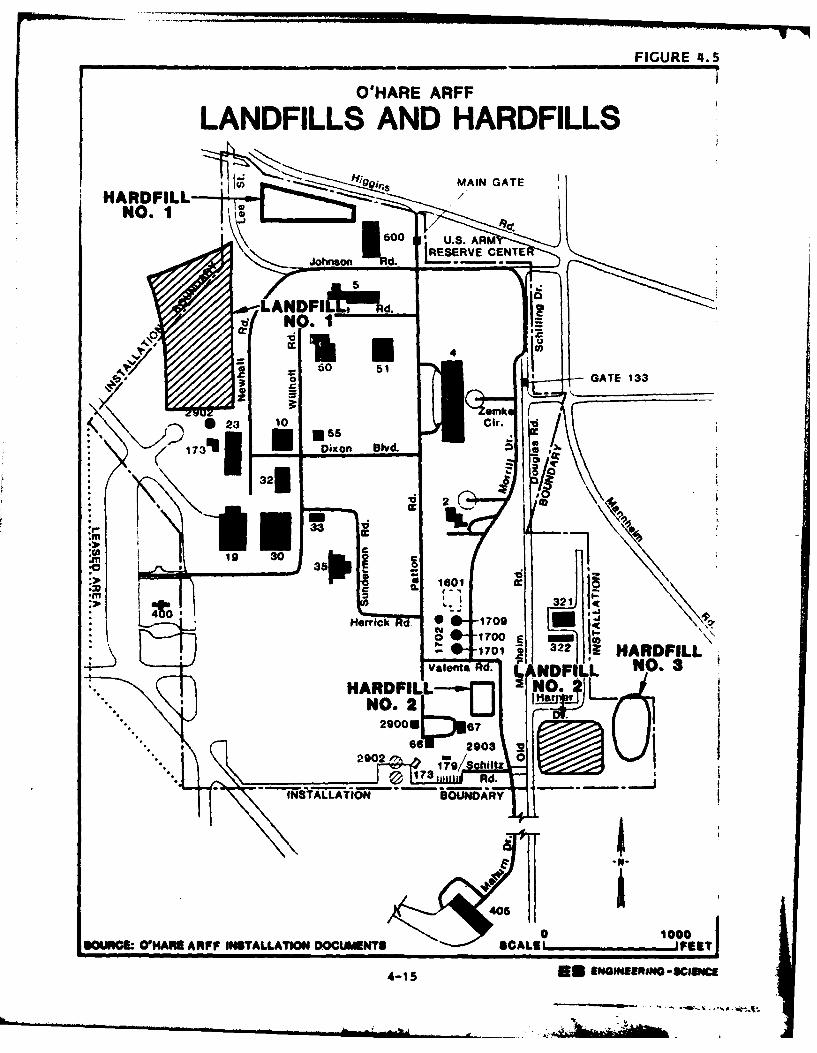
FIGURE 4. 5
O'HARE ARFF
LANDFILLS AND HARDFILLS
19 MAIN GATE
HARDFILL-NO. 1
ANDFI ~d.
00 5
170 Dixon ON&.
32K
gm 19 30
aLen 16 . cADcL O
.1 321"4 r40L
0erc Rd0000SOU~ N~hARPINTLLTONDCUETSSALE P4-15 ~~70 *EEGNE~N-CUc
73- .,2~
about 10 feet deep. The landfill received at least some portion of all
wastes generated on the installation, including general refuse and
office trash, old aircraft part, old kitchen-type appliances and both
new and old tools. It was also reported that some drummed waste from
the shop operations went into this landfill. There was occasional
burning at this landfill. The operation ceased in 1965 when the airport
runways were expanded. The site is closed and has an earth cover.
Holes dug by burrowing animals indicate that the landfill is close to
the present surface of the ground in the area.
Landfill No. 2 (1965-1972)
When Landfill No. 1 was closed, the landfill operation was moved to
southeast portion of the installation (Figure 4.5). Landfill No. 2 was
operated from 1965 through 1972. This landfill was operated in two
adjacent areas and was almost exclusively a trench and fill operation.
Part of Landfill No. 2 is located outside the O'Hare ARFF. The trenches
were about 10 feet deep. It continued to receive the same type of
wastes as disposed of at Landfill No. 1. Drums of shop wastes were
crushed and buried with earth-moving equipment. There was no burning of
waste at this site. The landfill is closed and has an earth cover.
Hardfills
Three hardfill sites were identified on O'Hare ARFF (Figure 4.5).
Hardfill No. 1 was operated during the early period of installation
operations. It received only construction materials. Hardfill No. 2
was operated during 1965 and received miscellaneous non-hazardous rubble
from the demolition at the old Assembly Plant Building. The site is
closed and is covered with soil. Hardfill No. 3, located by Landfill
No. 2 has received concrete rubble since 1965 and is still open.
Hardfill No. 3 is located over the old Fire Protection Training Area.
Storm Drainage System
The installation storm drainage system collects water runoff from
the civilian airport and the Air Force, installation at O'Hare and con-
veys it through both wooden and concrete pipes to an open drainage ditch
off of the installation property. This ditch in turn discharges to
Willow Creek. Although no shop wastes or other hazardous materials were
regularly disposed of to this system, intermittant spills have occasion-
ally entered the pipes. A number of the wooden pipe sections have
4-16
-~J
collapsed, indicating that any materials which have entered the system
have probably been in direct contact with the ground around it.
Sanitary Sever System
There is no treatment of sanitary wastewater on the base. Since
the beginning of the operation of the Douglas Aircraft Assembly Plant
through to the present day the network of sanitary sever piping has been
connected to the City of Chicago Sanitary District System. Typically
shop wastes and other hazardous materials do not enter the sanitary
sewer, with the exception of neutralized battery acid and photochemi-
cals.
Low-level Radiation Disposal Site
The low-level radiation disposal sites is located northeast of the
south POL tank farm (Figure 4.6). The site was used for disposal of
low-level radioactive vacuum tubes. The site was operated during the
1950's and 1960's and closed in the late 1960'.. The waste material was
placed in a pit about eight feet deep and then covered with earth.
There is no marking or fence at this site.
EVALUATION OF PAST DISPOSAL A CTI VITIES AND FACILITIES
The review of past operation and maintenance functions and past
waste management practices at O'Hare ARF? has resulted in the identi-
fication of 16 sites which were initially considered as areas of concern
with regard to the potential for contamination, as well as the potential
for the migration of contaminants. These sites were evaluated using the
Decision Tree Methodology shown in Figure 1.1. Those sites which were
considered as not having a potential for contamination were deleted from
further consideration. Those sites which were considered as having a
potential for the occurrence of contamination and migration of contami-
nants were further evaluated using the Hazard Assessment Rating Method-
ology (BRN) (Appendix H). Table 4.2 identifies the decision tree logic
used for each of the areas of intitial concern.
Based an the decision tree logic, five of the 16 sites originally
reviewed did not warrant evaluation using the Hazard Assessment Rating
Methodology. The rationale for omitting these five sites from HARM
evaluation is discussed below.
4-17
_ |
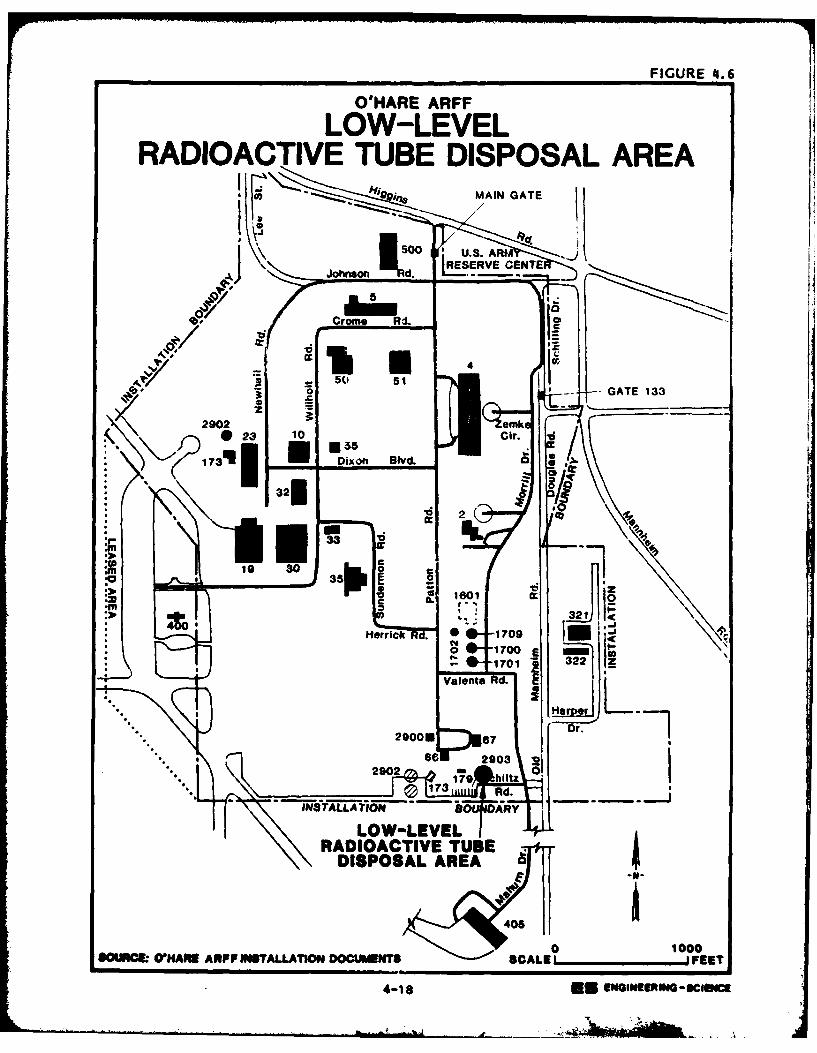
FIGURE 4.6
O'HARE ARFF
LOW-LEVELRADIOACTIVE TUBE DISPOSAL AREA
I MAIN GATE
jERVE C LTJonon d0 L9,...
'6 4
23ric 170 ir .
'd 2
OWE NAE RP IUALATO~DOUMNT CAE'_________
431 EUEGNmN-CSc
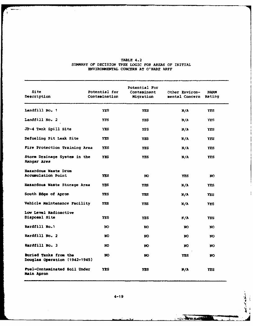
TABLE 4.2SUMMARY OF DECISION TREE LOGIC FOR AREAS OF INITIAL
ENVIRONMENTAL CONCERN AT O'HARE ARFF
Potential ForSite Potential for Contaminant Other Environ- HARM
Description Contamination Migration mental Concern Rating
Landfill No. 1 YES YES N/A YES
Landfill No. 2 YES YES N/A YES
JP-4 Tank Spill Site YES YES N/A YES
Defueling Pit Leak Site YES YES N/A YES
Fire Protection Training Area YES YES N/A YES
Storm Drainage System in the YES YES N/A YESHangar Area
Hazardous Waste DrumAccumulation Point YES NO YES NO
Hazardous Waste Storage Area YES YES N/A YES
South Edge of Apron YES YES N/A YES
Vehicle Maintenance Facility YES YES N/A YES
Low Level RadioactiveDisposal Site YES YES N/A YES
Hardfill No.1 NO NO NO NO
Hardfill No. 2 NO NO NO NO
Hardfill No. 3 NO NO NO NO
Buried Tanks from the NO NO YES NODouglas Operation (1942-1945)
Fuel-Contaminated Soil Under YES YES N/A YESMain Apron
4-19
U
Hardfill No. I was used for the disposal of construction rubble
only. This material is nonhazardous and would not cause any environ-
mental contamination.
Hardfill No. 2 was used for the disposal of building debris during
the demolition of the old Assembly Plant Building and received only
wood, concrete, glass and some plumbing piping. This material is non-
hazardous and hence would not cause any environmental contamination.
Hardfill No. 3 is used for the disposal of concrete and stone
rubble and as such, would not cause any environmental contamination.
Several underground tanks stored paint thinners and fuels for the
Douglas Aircraft Co. during the 1940's. All but one of these tanks have
since been excavated and removed. No reports were found of any leaks or
spills from these tanks and hence, the site poses no potential for con-
tamination of the environment.
The Hazardous Waste Drum Accumulation Point is loca-ted over a large
concrete pad. In the event of a spill, the wastes wo.ild not run off
onto the earth. Instead they would either stay where they were spilled
or they would enter the installation's storm sewer system. (The storm
sewer system is rated using the HARM method.) Hence, no potential for
environmental contamination exists at this site itself.
The remaining 11 sites identified on Table 4.2 were evaluated using
the Hazard Assessment Rating Methodology. The HARM process takes into
account characteristics of potential receptors, waste characteristics,
pathways for migration, and specific characeristics of the site related
to waste management practices. The details of the rating results are
summarized in Table 4.3. The HARM system is designed to be one of the
many indicators of the relative need for follow-on action. The infor-
nation presented in Table 4.3 is intended for assigning priorities for
further evaluation of the O'Hare ARFF disposal areas (Section 5,
Conclusions and Section 6, Recommendations). The rating forms for the
individual waste disposal sites at O'Hare ARFF are presented in Appendix
H. Photographs of some of the disposal sites are included in Appendix
F.
4-20
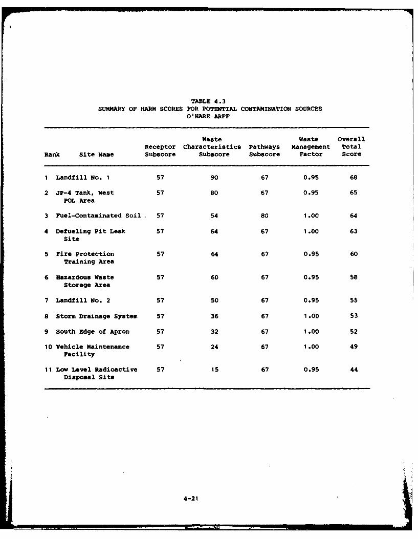
TABLE 4.3SUMMARY OF HARM SCORES FOR POTENTIAL CONTAMINATION SOURCES
O'HARE ARFF
Waste Waste OverallReceptor Characteristics Pathways Management Total
Rank Site Name Subscore Subscore Subscore Factor Score
1 Landfill No. 1 57 90 67 0.95 68
2 JP-4 Tank, West 57 80 67 0.95 65
POL Area
3 Fuel-Contaminated Soil 57 54 80 1.00 64
4 Defueling Pit Leak 57 64 67 1.00 63Site
5 Fire Protection 57 64 67 0.95 60Training Area
6 Hazardous Waste 57 60 67 0.95 58Storage Area
7 Landfill No. 2 57 50 67 0.95 55
8 Storm Drainage System 57 36 67 1 .00 53
9 South Edge of Apron 57 32 67 1 .00 52
10 Vehicle Maintenance 57 24 67 1.00 49Facility
11 Low Level Radioactive 57 15 67 0.95 44Disposal Site
4-21
SECTION 5
CONCLUSIONS
The goal of the IRP Phase I Study is to identify sites where there
is the potential for environmental contamination resulting from past
waste disposal practices and to assess the probability of contaminant
migration from these sites. The conclusions given below are based on
the assessment of the information collected from the project team's
field inspection, review of records and files, review of the environ-
mental setting, and interviews with installation personnel, past em-
ployees, and state and local government employees. Table 5.1 contains a
list of the potential contamination sources identified at O'Hare ARFF
and a summary of the HARN scores for those sites. The sites themselves
are discussed below.
LANDFILL NO. 1
Landfill No. I has a sufficient potential to create environmental
contamination and follow-on investigation is warranted. The landfill
was operated between 1953 and the mid 1960's and received various wastes
generated on the installation, including general refuse and office
trash, old aircraft parts, and drums containing shop wastes. The shop
wastes were probably spent solvents, waste oils and sludges. There was
occasional burning at this landfill and the waste is buried to a depth
of about 10 feet. The water table ts high and ground-water is very
likely in contact with the wastes. The site received a HARK score of
68.
JP-4 SPILL SITE
The JP-4 Tank spill. site has a sufficient potential to create en-
vironmental contamination and follow-on investigation is warranted. In
1972, an 82,000 gallon spill of JP-4 occurred at the west POL area. The
spill was contained inside the dike area and 40,000 gallons of JP-4 was
5-1
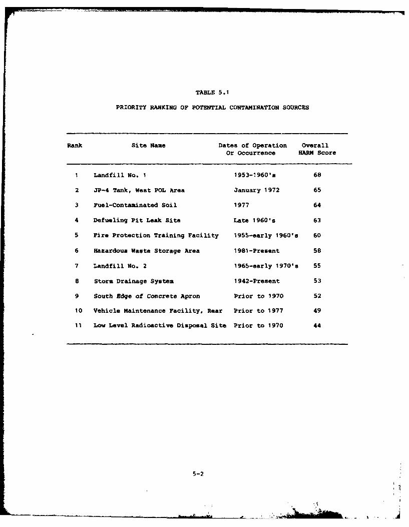
TABLE 5.1
PRIORITY RANKING OF POTENTIAL CONTAMINATION SOURCES
Rank Site Name Dates of Operation OverallOr Occurrence HARM Score
1 Landfill No. 1 1953-1960's 68
2 JP-4 Tank, West POL Area January 1972 65
3 Fuel-Contaminated Soil 1977 64
4 Defueling Pit Leak Site Late 1960's 63
5 Fire Protection Training Facility 1955-early 1960's 60
6 Hazardous Waste Storage Area 1981-Present 58
7 Landfill No. 2 1965-early 1970's 55
8 Storm Drainage System 1942-Present 53
9 South Edge of Concrete Apron Prior to 1970 52
10 Vehicle Maintenance Facility. Rear Prior to 1977 49
11 Low Level Radioactive Disposal Site Prior to 1970 44
5-2
recovered. The remaining estimated 42,000 gallons of JP-4 either
evaporated or infiltrated into the ground. The water table is high in
this area and the fuel likely contacted the water table in the upper
glacial drift. The site received a HARM score of 65.
FUEL-CONTAMINATED SOIL
The fuel-contaminated soil under the main apron indicates that
there is a sufficient potential created for environmental contamination
and follow-on investigation is warranted. When discovered in 1977, the
soil was described as "saturated with jet fuel." The site received a
HARM score of 64.
DEFUELING PIT LEAK
The defueling pit leak site has a sufficient potential to create
environmental contamination and follow-on investigation is warranted.
This 12,000 gallon underground tank developed a leak which was present
for an undetermined period of time prior to its discovery in the late
1960's, when water appeared in the fuel passing through this tank. The
amount of JP-4 lost is not known. The site received a HARM score of 63.
FIRE PROTECTION TRAINING AREA
Fire Protection Training Area has a sufficient potential to create
environmental contamination and follow-on investigation is warranted.
From approximately 1955 to the early 1960es, the installation fire
department conducted fire training exercises in an area on the southeast
side of the installation. The burn pit was constructed with a soil
bottom and an earth berm around it. Contaminated fuels (AVGAS, MOGAS)
and combustible liquid wastes were burned during fire protection train-
ing exercises. The site is now covered by a hardfill. This site
received a HARM score of 60.
HAZARDOUS WASTE STORAGE AREA
The Hazardous Waste Storage Area has a sufficient potential to
create environmental contamination and follow-on investigation is
warranted. This storage area is located in a depressed area at the
south end of the Old Assembly Plant foundation (a former truck loading
5-3 $
area). The soil in this storage area was darker than normal, indicating
that past spills have occurred. This site received a HARM score of 58.
LANDFILL NO. 2
Landfill No. 2 has a sufficent potential to create environmental
contamination and follow-on investigation is warranted. This landfill
was in operation from the mid 1960's through 1972 and was operated in
two adjacent areas in a trench and fill manner. A portion of this
landfill is located outside of O'Hare ARFF property. Trenches were
about 10 feet deep. it received general refuse, office trash and some
shop wastes. Some drums of shop wastes were crushed with earth moving
equipment. There was no burning of waste at this site. The landfill is
closed and covered. The water table is high and ground water is very
likely in contact with the wastes. The site received a HAR14 score of
55.
STORM DRAINAGE SYSTEM NEAR HANGARS
The Storm Drainage System in the Aircraft hangar area has a suf-
ficient potential to create environmental contamination and follow-on
investigation is warranted. The system in this area has probably
received shop wastes from the hangars. Also, liquid hazardous wastes
are accumulated in an area which drains directly into this wood- and
concrete-pipe system. The system received a HARM score of 53.
SOUTH EDGE OF APRON
The south edge of the main concrete apron has a sufficient poten-
tial to create environmental contamination and follow-on investigation
is warranted. This area was occasionally used as a dumping area for
small quantities of liquid wastes from the shops in the 1950's and
1960's. A stormwater drainage ditch runs parallel to the edge, about
ten feet away. During the site visit, no environmental stress was
observed in this area. The site received a HARM score of 52.
VEHICLE MAINTENANCE FACILITY
The rear of the vehicle maintenance factlity has an insufficient
potential to create environmental contamination and no follow-on
5-4
investigation is warranted. Motor oil was dumped on the ground north of
Building No. 5 from the early 1950's until about 1975. The area behind
the building has been covered over by a concrete vehicle parking lot.
The contaminated soil may have been removed when the parking lot was
built. The site received a HARM score of 49.
LOW-LEVEL RADIOACTIVE DISPOSAL SITE
The low-level radioactive disposal site has an insufficient po-
tential to create environmental contamination and no follow-on investi-
gation is warranted. This area was used for the disposal of vacuum
tubes during the 1950's and the 1960's. The site received a HARM score
of 44.
5-5 U
SECTION 6
RECOMMENDATIONS
Eleven sites were identified at O'Hare ARFF as having the potential
f or environmental contamination and have been evaluated using the HARM
system. This evaluati3n assessed their relative potential for environ-
mental contamination and along with relevant site specific information
identified those sites where further study and monitoring may be neces-
sary. Nine of the sites were determined to have sufficient evidence to
indicate the potential for environmental contamination. Additional data
concerning these sites will be required in order to clearly ascertain
whether or not these sites have contributed environmental contamination.
Therefore, the following recommendations have been developed for each of
the nine sites. There was insufficient evidence on the other two sites
to warrant further investigation.
PHASE II MONITORING RECOMMENDATIONS
The following recommendations are made to further assess the
potential for environmental contamination from waste disposal areas at
O'Hare ARFF. The recommended actions are generally one-time sampling
programs to determine if contamination does exist at the site. If con-
tamination is identified, the sampling program may need to be expanded
to further define the extent of contamination.
Geophysical surveys, consisting of electrical resistivity, electro-
magnetic and/or magnetometer techniques, are recommended prior to any
well installations to attempt to delineate the horizontal and vertical
extent of the site, subsurface leachate plumes migrating from the site,
and subsurface stratigraphy including the hardpan formation. The alter-
native approach to geophysical testing would be the conventional tech-
nique to test well drilling and ground-water sampling. The cost benefit
6-1
of geophysical surveys over test drilling can be understood by compari-
sons of time, cost and data availability. Table 6.1 presents general
guidelines for the use of certain geophysical techniques.
The recommended monitoring program for Phase II is summarized in
Table 6.2.
1) Landfill No. 1 has a sufficient potential to create environmental
contamination and monitoring of this site is recommended. A geo-
physical survey should be conducted to define the landfill
boundaries and depth, and identify any leachate plume. Based on
the results of the geophysical survey, one upgradient and 3 down-
gradient monitoring wells should be installed. Wells should be
constructed using 3" Schedule 40 PVC, screened intc the first sand
and gravel lens (20' to 30' deep). Sample these wells and analyze
for pH, total dissolved solids, total organic halogen, total
organic carbon, oil and grease, and phenol.
2) The JP-4 Tank Dike Spill Site has a sufficient potential to create
environmental contamination and further monitoring of this site is
recommended. A geophysical survey should be conducted around the
tank farm to identify any JP-4 plume. Conduct a continuous core
sampling in the dike area extended to the first sand and gravel
lens and observe if any JP-4 is present. Then perform a water
extract on 3 soil samples and analyze for oil and grease, and total
organic carbon.
3) The Fuel-contaminated Soil area indicates that there is a suf-
ficient potential to create environmental contamination and further
monitoring of this site is recommended. A geophysical survey
should be conducted around the area to define the extent of the
fuel plume and to locate its source, if possible. Conduct a
continuous core sampling as near to the sites as possible, extended
to the first sand and gravel lens (20' to 30' deep) and observe if
any JP-4 is present. Then perform a water extract on 3 soil samp-
les and analyze for oil and grease and total organic carbon. If a
6-2
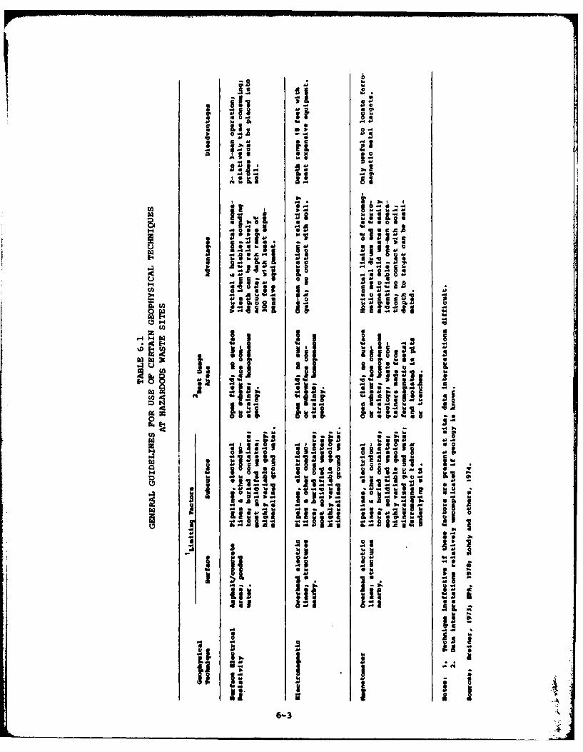
41 60
*~3 iiI~
d .
-0
U) -.I. 6
-4 H-
U) ~'; 3 3 IBM * 48
2 a La A 6 1
L~~ LA~e
-A .40 IN'
U) i~-~liftU)~~~~ 61I~I .~13 .
-4~" .:g.
6-3
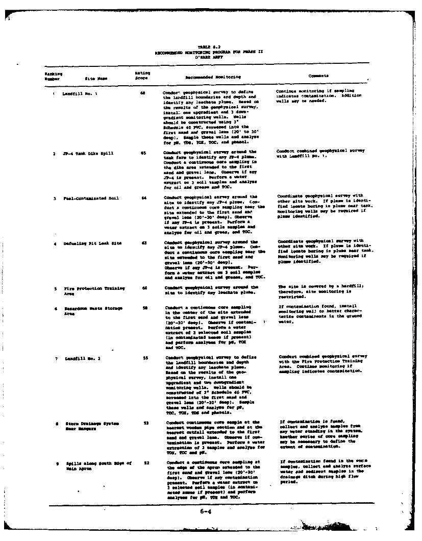
Raking RatingNumber Site gem scare aecmende mnaitoring; Comments
I Landfill NO. 1 68 Coaduceopimia survey to define. Continue smitoring if samplingthe landfill boundaris and depth and indicates ,ntawirtetion. Addition
identitty anY Ieachete Pluame. Based OR weells may us needed.the results of the geophysical survey,inetel: e upgredleat end 3 dowa-gradient *Mitoring wells. Wall@should be cnstructed using 5'Schedule 40 PVC. ree into thefirst sand wit grovel mum (201 to 30'do")~. sample thee. ue'll and enelysofor pp. M3. TOM, IOC. sod phenol.
2 J"- Tank Dike Spill 65 conuct geophysical survey around the Conduct comined jeoghyiiol survey
teak fern to identify ay V1-4 Plum. With .adfill 30. 1.Conduct a cntinuous care smpling inth, dike area exteaded to the firstnend A"d graVOI IOTA. Obeerve if any31-4 is Present. Perform a mterextract on 3 sail Itaxl~m and en&lymefor oil and greame aPd ICC.
3 Fuel-Contaminated Soil 64 Conduct geophysical survey around the coordinate geopysical sorvey with
mite to Identify ay 31-4 PLUM. Coo- other site work. If plume is identi-
duct a continuous care "emling naer the find Leat* boring in plum ear tank.
mite extended to the first mend enE hamtoring ells my be required if
gravel leow (201*-30 * deep). observe plumw identified.it may S1-4 iu present. Purform awater extract an 3 SmilaSameples endanelyse tow oil en* green. mmd IOC.
4 Deneling Pit Lea Site 63 Cadect veophyniomi murvey around the Coordinete aphysiaml surve withsite to idienity ay 31-4 pam. Con- other mite wook. If plume to ideuti-
mite offtended to the first "ead end monitoring wells my be required if
irmeel- les W0-301 deep), Plume identified.Observe it anf 31-4 is rmet Par-to= & a ter extract om 3 emil w"meend &=IT" for a"l end greame. end IOC.
5 Fire Protection Training 60 Conduct geophysical morvey arond the The site incoavered by a berdt IP,
Area mite to Identify any leechate plum. therefore, it montoering inrestricted.
6 Nsemedous Wmts storage so Conduct a cootinuft cage emping It contanimtiie toand, install
Atea in the center ot the site extended monitoring wal~l to batter cheres-to the first mend and grave low toring cantmnir~ets in the ground
(201-30 deep). observe It contet- wamter.ntice present. Perform a moterextrat of 3 soleated eoil samles(in contaminated %oen if Preeent)ad Peorm anelysee fog Do. 202
end ICC.
7 Ladill IDo. 2 SI Conduct -eogFmiLatl movey to define Conduct caondgeophysicel surveythe landf ill boundaris end deyth with the lire Protection ?raininq
end identify eny leechate plume. Arma. Continee moanitoring If
Seine on the reeults of the geo- memling Indicatee coateminetiat'.Yhysical ozuVey, Install aesupgredlent &nd tw dowagradisetmonitoring wells. walle eboold betonstmucted of 31 Schedule 46 79C.
moreene iato the firet sand andgravel lAne (201-30 dee). Sampletheme wells ad anelyue for VS,
OM. 1sm. as6 and phefeolm.
S storm Drainage system 93 Conduct omtifaum cors *oes at te If onmtanmetiat Is toond,
Dear Nn"mm neareet wosd.. pipe section and at the collect eod em.llue samples f ruenaset outfall extended to the first ay water stendiaq in the system'.
send and grave leaw. Observ It coa- atier "eri" of moe empU~ngtemetim to present. Parseas a aster may be mensmeen to define the
streatim of 3 samples snd analyms fmr cxtent of coet~netIon.M,1 Ice ad vs.
9 Spilim along South sage Of 52 Conduct a ontieeantowee wemliag at if samination f sed in the coc
van Agree the edo" a1 the Wpoo extended to the @seplee. collect and ealym murt ce
tirst e"ad snd groel lenow 0 0 eter oe sediment smplee An the
deep). Obserer if any aMMStaILeionU drainege *itch duringr high flowpresent. Performn a meter entrat as peried.2 Seleted soil easples (in ositeti-mated smoe If I Sm -- tU aod pert mnselye for VE, IN3 Sad Ice.
6-4
plume was identified during the survey, the boring should be lo-
cated to intercept the plume. Monitoring wells may be required if
a plume is identified.
4) The Defueling Pit Leak Site has a sufficient potential to create
environmental contamination and further monitoring of the site is
recommended. A geophysical survey should be conducted around the
site to identify any JP-4 plume. Conduct a continuous core samp-ling by the site extended to the first sand and gravel lens (20' to
30' deep) and observe if any JP-4 is present. Then perform r water
extract on 3 selected soil samples (in the contaminated zone, if
present) and analyze for oil and grease, and total organic carbon.
If a plume was identified during the survey, the boring should be
located to intercept the plume. Monitoring wells may be required
if a plume is identified.
5) The Fire Protection Training Area has a sufficient potential tocreate environmental contamination and further monitoring of thesite is recommended. A geophysical survey should be conducted toidentify any leachate plume. Further investigation of the site isto be coordinated with that of Landfill No. 2, discussed below.
6) The Hazardous Waste Storage Area has a sufficient potential to
create environmental contamination and further monitoring of thesite is recommended. Any old drums in the area should be locatedand examined. Conduct a continuous core sampling in the center of
the site extended to the first sand and gravel lens (20' to 30'
deep) and observe if contamination present. Perform a water ex-
tract of 3 selected soil samples (in contaminated zones if present)
and analyze for pH, total organic halogen and total organic carbon.
7) Landfill No. 2 has a sufficient potential to create environmental
contamination and further monitoring of the site is recommended.
First conduct a geophysical survey (simultaneous with the Fire
Protection Training Area, above) to define the landfill boundaries
and depth, and identify any leachate plume. Based on the results
6-5 4
of the geophysical survey, install one upgradient and two down-
gradient monitoring wells. Wells should be constructed of 3"
Schedule 40 PVC, screened into the first sand and gravel lens (20'
to 30' deep). Sample these wells and analyze for pH, total organic
carbon, total organic halogen, total dissolved solids and phenols.
8) The Storm Drainage System in the aircraft hangar area has a suf-
ficient potential to create environmental contamination and further
monitoring of the system is recommended. First, the sections which
are wooden pipe nearest the hangars should be identified. The
nearest outfall should also be identified. Then conduct a con-
tinuous core samplang at each point extended to the first sand and
gravel lens (20' to 30' deep) and observe if any contamination is
present. Perform a water extract on 3 selected soil samples from
each point and perform analyses for total organic halogen, total
organic carbon, and pH. If contamination is found in either core
sample, collect and analyze water samples from any water found
standing in the system. Another series of core samples ray be
necessary to define the extent of any contamination.
9) The Spill Area along the South Edge of the Main Apron has a suf-
ficient potential to create environmental contamination and further
monitoring of the site is recommended. First, conduct a continuous
core sampling at the edge of the apron extended to the first sand
and gravel lens (20' to 30' deep) and observe if any contamination
is present. Perform a water extract on 3 selected soil samples in
contamination zones if present) and perform analyses for pH, total
organic halogen and total organic carbon. If contamination is
found in the core samples, collect and analyze surface water and
sediment samples in the drainage ditch during a high flow period.
OTHER RECONEDATIONS
The following items did not warrant HARM ratings but are signi-
ficant to the protection of the environmental at O'Hare ARFF. It is
recommended that the installation environmental program incorporate
these recommendations into its overall plan.
6-6
. . . , . .I
I) The oil/water separator located near Building No. 19 (both the
main tank and its overflow tank) should be emptied and it should
be verified that the water overflows into the sanitary sewer.
Regular monitoring and periodic emptying of this separator is
recommended.
2) The location of Hazardous Waste Accumulation Point near the
aircraft hangars should be reevaluated in light of the pos-
sibility of a spill entering the storm sewer.
3) The abandoned MOGAS tank(s) at the south edge of the Main Apron
should be checked for any contents and either removed or filled
with sand.
4) A sign should be permanently posted at the low-level radioactive
disposal site identifying it as such.
6-7
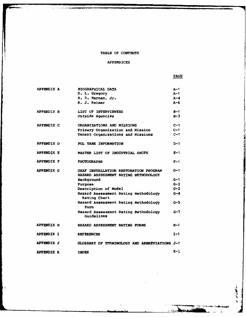
TABLE OF CONTENTS
APPENDICES
PAGE
APPENDIX A BIOGRAPHICAL DATA A-iD. L. Gregory A-iH. D. Harman, Jr. A-4
R. J. Reimer A-6
APPENDIX B LIST OF INTERVIEWEES B-iOutside Agencies B-3
APPENDIX C ORGANIZATIONS AND MISSIONS C-iPrimary Organization and Mission C-ITenant Organizations and Missions C-1
APPENDIX D POL TANK INFORMATION D-i
APPENDIX E MASTER LIST OF INDUSTRIAL SHOPS E-1
APPENDIX F PHOTOGRAPHS F-I
APPENDIX G USAF INSTALLATION RESTORATION PROGRAM G-iHAZARD ASSESSMENT RATING METHODOLOGYBackground G- 1Purpose G-2Description of Model G-2Hazard Assessment Rating Methodology G-4Rating Chart
Hazard Assessment Rating Methodology G-5Form
Hazard Assessment Rating Methodology G-7Guidelines
APPENDIX H HAZARD ASSESSMENT RATING FORMS H-i
APPENDIX I REFERENCES I-I
APPENDIX J GLOSSARY OF TPMMINOLOGY AND ABBREVIATIONS J-1
APPENDIX K INDEX K-1
A
APPENDIX A
BIOGR~APHICAL DATA
D. L. Gregory, Project Manager A-1H. D. Harmani, Jr. A-4R. J. Reimner A-6
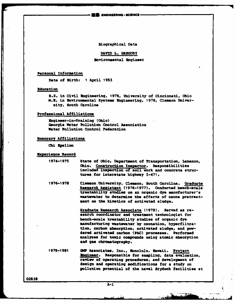
Biographical Data
DAVID L. GREGORY
Environmental Engineer
Personal information
Date of Birth: 1 April 1953
Education
B.S. in Civil Engineering, 1976, University of Cincinnati, OhioX.U. in Environmental Systems Engineering, 1978, Clemson Univer-
sity, South Carolina
Professional Affiliations
Engineer-in-Traininq (Ohio)Georgia Water Pollution Control AssociationWater Pollution Control Federation
Bonorary Affiliations
Chi psilon
Experience Record
1974-1975 State of Ohio, Department of Transportation, Lebanon,Ohio* Constuction Inspector. Responsibilitiesincluded inspection of soil work and concrete struc-tures for interstate highway 1-471.
1976-1978 Clemson University, Clemson, South Carolina. GraduateResearch Assistant (1976-1977). Conducted bench-scaletreatability studies on an organic dye manufacturer'swastewater to determine the effects of ozone pretreat-ment on the kinetics of activated sludge.
Graduate Research Associate (1978). Served as re-search coordinator and treatment technologist forbench-scale treatability studies of organic dyemanufacturing vastewater by ozonation, hyperfiltra-tion, carbon absorption, activated sludge, and pow-dered activated carbon (PAC) processes. Perforuedanalyses for toxic compounds using atomic absorptionand gas chromatography.
1979-1961 GNP Associates, Inc., Nonolulu, awaii. ProjectEngineer. Responsible for sampling, data evaluation,review of operating procedures, and development ofdesign and operating modifications for a study onpollution potential of the naval drydock facilities at
02830
A-1
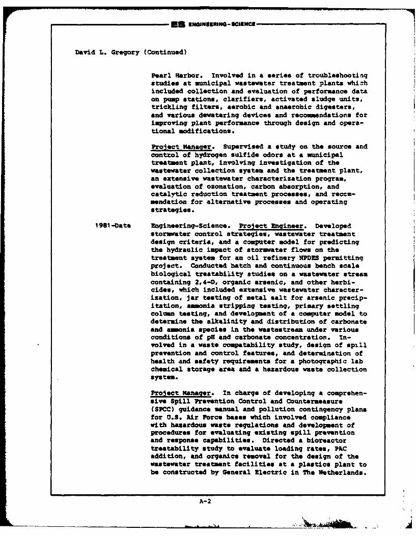
En ENGINEERNG - OCIENCE
David L. Gregory (Continued)
Pearl Harbor. Involved in a series of troubleshootingstudies at municipal wastewater treatment plants whichincluded collection and evaluation of performance dataon pump stations, clarifiers, activated sludge units,trickling filters, aerobic and anaerobic digesters,and various dewatering devices and recommendations forimproving plant performance through design and opera-tional modifications.
Project Manaqer. Supervised a study on the source andcontrol of hydrogen sulfide odors at a municipaltreatment plant, involving investigation of thewastewater collection system and the treatment plant,an extensive wastewater characterization program,evaluation of ozonation, carbon absorption, andcatalytic reduction treatment processes, and recem-mendation for alternative processes and operatingstrategies.
1981-Date Engineering-Science. Project Zngineer. Developedstoruwater control strategies, wastewater treatmentdesign criteria, and a computer model for predictingthe hydraulic impact of storuawter flows on thetreatment system for an oil refinery NPDRS permittinqproject. Conducted batch and continuous bench scalebiological treatability studies on a wastewater streamcontaining 2,4-4, organic arsenic, and other herbi-cides, which included extensive wastewater character-ization, jar testing of metal salt for arsenic precip-itation, ammonia stripping testing, primary settlingcolumn testing, and development of a computer model todetermine the alkalinity and distribution of carbonateand ammonia species in the wastestream under variousconditions of pH and carbonate concentration. In-volved in a waste compatability study, design of spillprevention and control features, and determination ofhealth and safety requirements for a photographic labchemical storage area and a hazardous waste collectionsystem.
Project Manager. In charge of developing a comprehen-sive Spill Prevention Control and Countermeasure(SPCC) guidance manual and pollution contingency plansfor U.S. hir Force bases which involved compliancewith hazardous waste regulations and development ofprocedures for evaluating existing spill preventionand response capabilities. Directed a bioreactortreatability study to evaluate loading rates, PACaddition, and organics removal for the design of thewastewater treatment facilities at a plastics plant tobe constructed by General lectric in The Netherlands.
A-2
EU ENGNuEUfanG - SCIENCE
David L. Gregory (Continued)
Papers and Presentation*
"Bioloqical Treatability of an Ozonated Dye Manufacture Waste,"Master of Engineering Special Problem Report, Clemon University,anviromontal Systems Inqineering Departnent, Clemon, South Caro-lina, 1979.
A-3
Biographical Data
H. DAN HARMAN, JR.Hydrogeologist
Personal Information
Date of Birth: 7 December 1948
Education
B.S., Geology, 1970, University of Tennessee, Knoxville, TN
Professional Affiliations
Registered Professional Geologist (Georgia NO.569)National Water Well Association (Certified Water Well DrillerNo. 2664)Georgia Ground-Water Association
Experience Record
1975-1977 Northwest Florida Water Management District, Havana,Florida. Hydrogeologist. Responsible for boreholegeophysical logger operation and log interpretation.Also reviewed permit applications for new water wells.
1977-1978 Dixie Well Boring Company, Inc., LaGrange, Georgia.Hydrogeologist/Well Driller. Responsible for boreholegeophysical logger operation and log interpretation.Also conducted earth resistivity surveys in Georgia andAlabama Piedmont Provinces for locations of water-bearing fractures. Additional responsibilities includeddrilling with mud and air rotary drilling rigs as wellas bucket auger rigs.
1978-1980 Law Engineering Testing Company, Inc., Marietta,Georgia. Hydrogeologist. Responsible for ground-waterresource evaluations and hydrogeological fieldoperations for government and industrial clients. Amajor responsibility was as the Mississippi FieldHydrologist during the installation of both fresh andsaline water wells for a regional aquifer evaluationrelated to the possible storage of high level radio-active waste in the Gulf Coast Salt Domes.
1980-1982 Ecology and Environment, Inc., Decatur, Georgia.Hydrogeologist. Responsible for project management ofhydrogeological and geophysical investigations atuncontrolled hazardous waste sites. Also preparedEergency Action Plans and Remedial Approach Plans forU.S. Environmental Protection Agency. Additional
6/83
A-4
Oak
H. Dan Harman, Jr. (Continued)
responsibilities included use of the MITRE hazardousranking system to rank sites on the National SuperfundList.
1982-1983 NUS Corporation, Tucker, Georgia. Hydrogeoloist.Responsible for project management of hydrogeologicaland geophysical investigations at uncontrolled hazardouswaste sites.
1983-Date Engineering-Science, Inc., Atlanta, Georgia.Hydrogeoloqist. Responsible for hydrogeologicalevaluations during Phase I Installation RestorationProgram projects for the Department of Defense.
Publications and Presentations
"Geophysical Well Logging: An Aid in Georgia Ground-Water Projects,*1977, coauthor: D. Watson, The Georgia Operator, Georgia Water andPollution Control Association.
"Use of Surface Geophysical Methods Prior to Monitor Well Drilling,"1981. Presented to Fifth Southeastern Ground-Water Conference,Americus, Georgia.
"Cost-Effective Preliminary Leachate Monitoring at an UncontrolledHazardous Waste Site," 1982, coauthor: S. Hitchcock. Presented to ThirdNational Conference on Management of Uncontrolled Hazardous Waste Sites,Washington, D.C.
"Application of Geophysical Techniques as a Site Screening Procedure atHazardous Waste Sites," 1983, coauthor: S. Hitchcock. Proceedings ofthe Third National Symposion and Exposition on Aquifer Restoration andGround-Water Monitoring, Columbus, Ohio.
A-5 3
#67Biographical Data
ROBERT J R %EIMER
Chemical Engineer
Personal Information
Date of Birth: 12 April 1956
Education
B.S. in Chemical Engineering, 1979, University of Notre DameS.A. in Art, 1979, University of Notre DameM.S. in Chemical Engineering, 1980, University of Notre Dame
Honors
Amoco Company Fellowship for Graduate Studies in ChemicalEngineering, University of Notre Dame (1979-1980)
Professional Affiliations
American Institute of Chemical Engineers
Experience Record
1978-1979 PEDCo Environmental, Cincinnati. Engineer's Assistant.Responsible for compilation of data base report review-ing solid waste disposal in the nonferrous smeltingindustry. Participated in SO2 scrubber emissions test-ing program, Columbus, Ohio. Worked on team establish-ing a computerized reference file on the overall smelt-ing industry. Performed technical editing and reportreview.
1979-1980 Camargo Associates, Ltd., Cincinnati. Design Engineerand Draftsman. Responsible for RVAC design on numerousprojects. Designed fire protection system for an in-dustrial plastics press. Designer on various generalplumbing jobs. Prepared EPA air pollution permit ap-plications.
1980-Date Engineering-Science. Chemical Engineer. Responsiblefor the preparation of environmental reports and permitdocuments as well as providing general environmentalassistance to clients to assure compliance with stateand federal regulations.
3/83
A-6
Robert J. Reiner (Continued)
1980-Date Developed cost estimates for several hazardous wasteanagement facility closures. Prepared several Interim
Status Standards Manuals, including Manifest Plans,Waste Analysis Plans, Closure Plans and Contingency/Emergency Plans. Provided technical assistance in thedesign of a one-million gallon per year fuel alcohol
production facility.
Provided assistance for a water reuse/reduction plan ata major petroleum refinery. Conducted an extensivereview of emerging energy technologies for the Depart-ment of Energy. Participated in several InstallationRestoration Programs for the U. S. Air Force. Assistedin the design of a contaminated ground water air strip-ping column based on a lab model to be developed. Pre-pared several delistinq petitions for the removal ofindustrial wastestreams from EPA's hazardous waste list.Assisted in a study of waste oil reuse for the U.S. ArmyCIL.
A-7-7
APPENDIX B
LIST OF INTERVIEWEES
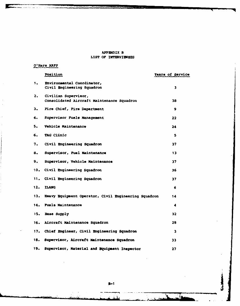
APPENDIX B
LIST OF INTEVIDEES
O'Hare ARFF
Position Years of Service
11 Environmental Coordinator,Civil Engineering Squadron 3
2. Civilian Supervisor,Consolidated Aircraft Maintenance Squadron 38
3. Fire Chief, Fire Department 9
4. Supervisor Fuels Management 22
5. Vehicle Maintenance 24
6. TAG Clinic 5
7. Civil Engineering Squadron 37
8. Supervisor, Fuel Maintenance 13
9. Supervisor, Vehicle Maintenance 37
10. Civil Engineering Squadron 36
11. Civil Engineering Squadron 37
12. ILANG 6
13. Heavy Equipment Operator, Civil Engineering Squadron 14
14. Fuels Maintenance 4
15. Base Supply 32
16. Aircraft Maintenance Squadron 28
17. Chief Engineer, Civil Engineering Squadron 3
18. Supervisor, Aircraft maintenance Squadron 33
19. Supervisor, Material and Equipment Inspector 27
51-1
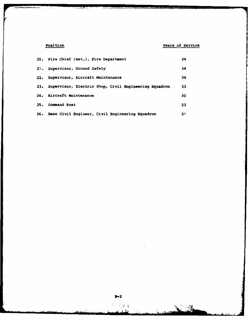
Position Years of Service
20. Fire Chief (Ret.), Fire Department 24
21. Supervisor, Ground Safety 34
22. Supervisor, Aircraft Maintenance 34
23. Supervisor, Electric Shop, Civil Engineering Squadron 33
24. Aircraft Maintenance 30
25. Command Post 23
26. Base Civil Engineer, Civil Engineering Squadron 21
3-2
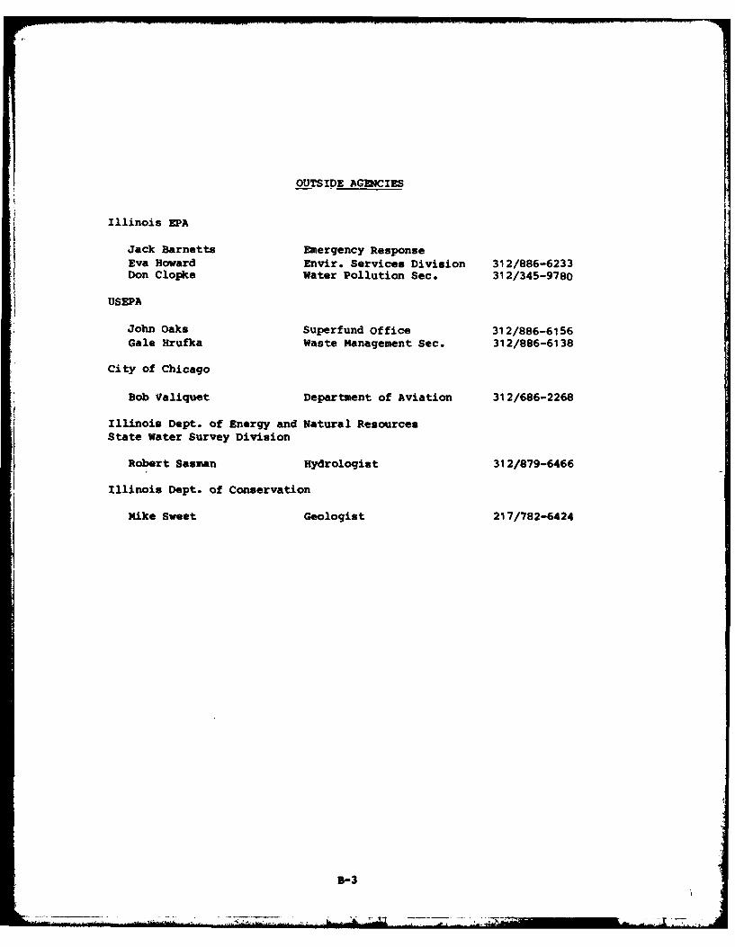
OUTSIDE AGENCIES
Illinois EPA
Jack Barnetts Emergency ResponseEva Howard Envir. Services Division 312/886-6233Don Clopke Water Pollution Sec. 312/345-9780
USEPA
John Oaks Superfund Office 312/886-6156Gale Hrufka Waste Management Sec. 312/886-6138
City of Chicago
Bob Valiquet Department of Aviation 312/686-2268
Illinois Dept. of Energy and Natural ResourcesState Water Survey Division
Robert Sasman Hydrologist 312/879-6466
Illinois Dept. of Conservation
Mike Sweet Geologist 217/782-6424
B-3
APPENIDIX C
ORGANIZATIONS AND MISSIONS
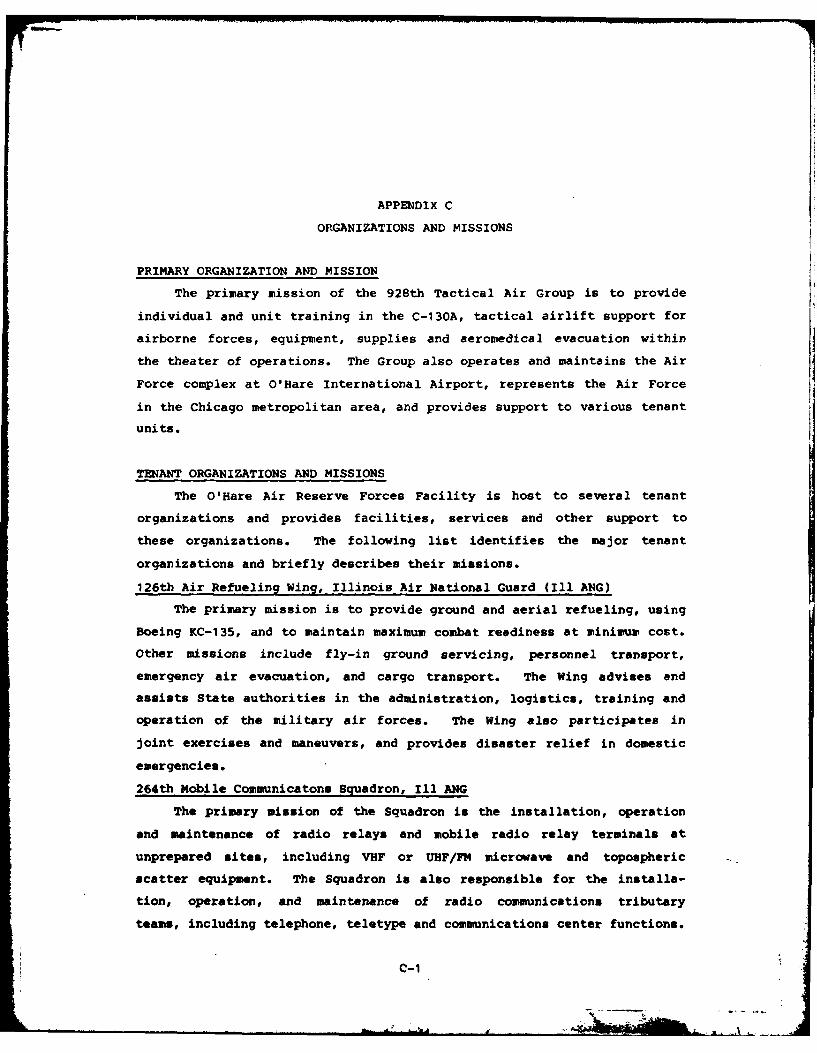
APPENDIX C
ORGANIZATIONS AND MISSIONS
PRIMARY ORGANIZATION AND MISSION
The primary mission of the 928th Tactical Air Group is to provide
individual and unit training in the C-130A, tactical airlift support for
airborne forces, equipment, supplies and aeromedical evacuation within
the theater of operations. The Group also operates and maintains the Air
Force complex at O'Hare International Airport, represents the Air Force
in the Chicago metropolitan area, and provides support to various tenant
units.
TENANT ORGANIZATIONS AND MISSIONS
The O'Hare Air Reserve Forces Facility is host to several tenant
organizations and provides facilities, services and other support to
these organizations. The following list identifies the major tenant
organizations and briefly describes their missions.
126th Air Refueling Wing, Illinois Air National Guard (Ill ANG)
The primary mission is to provide ground and aerial refueling, using
Boeing KC-135, and to maintain maximum combat readiness at minimum cost.
Other missions include fly-in ground servicing, personnel transport,
emergency air evacuation, and cargo transport. The Wing advises end
assists State authorities in the administration, logistics, training and
operation of the military air forces. The Wing also participates in
joint exercises and maneuvers, and provides disaster relief in domestic
emergencies.
264th Mobile Communicatons Squadron, Ill ANG
The primary mission of the Squadron is the installation, operation
and maintenance of radio relays and mobile radio relay terminals at
unprepared sites, including VHF or UHF/FM microwave and topospheric
scatter equipment. The Squadron is also responsible for the installa-
tion, operation, and maintenance of radio communications tributary
teams, including telephone, teletype and communications center functions.
c-1
217th Electronics Installation Squadron, III ANG
The Squadron is responsible for installation and maintenance of
ground communication-electronics equipment. The squadron consists of
four ground radio communications equipment teams, two telephone switching
teams, eight outside wire and antenna systems teams and sixteen cable
splicing teams.
36th Medical Service Evacuation Squadron
This Squadron trains to fulfill its wartime mission of providing
aeromedical staging at fixed medical facilities or other designated
locations.
USAF Liaison Office/National Scouting Organization
This office administers the USAF program of cooperation with the Boy
Scouts of America. The office acts as liaison between Air Force instal-
lations and scouts within Boy Scout Region VII (Illinois, Indiana,
Michigan, Wisconsin and eastern Iowa).
Additional Tenants
Defense Contract Administration Services Region
Defense Logistics Agency
Headquarters, Ill ANG
126th Combat Support Group, Ill ANG
126th Consolidated Aircraft Maintenance Squadron, Ill ANG
126th USAF Clinic, Ill ANG
126th Civil Engineering Flight, Ill ANG
566th USAF Band, Ill ANG
Aeronautical Systems Division, Reserve Detachment (AFLC)
Corps of Engineers Field Office
C-2
APPEN~DIX D
POL TANK INFORMATION
Al, A "-- 4
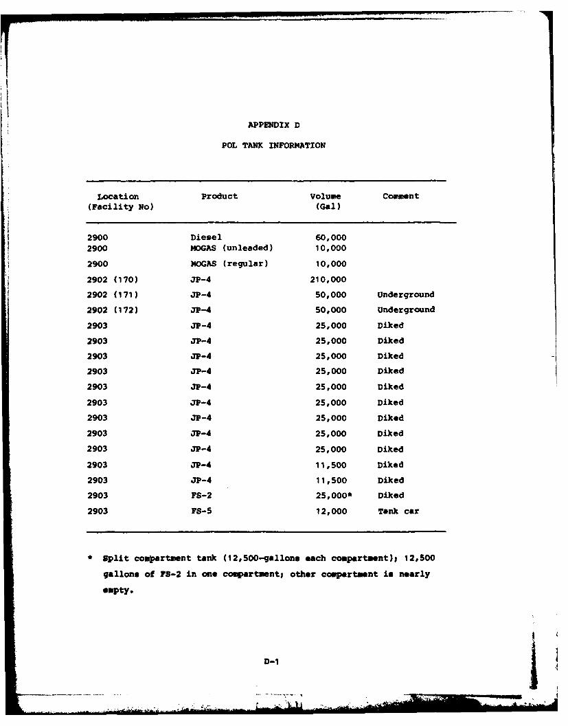
iim
APPENDIX D
POL TANK INFOR14ATION
Location Product Volume Comment(Facility No) (Gal)
2900 Diesel 60,000
2900 MOGAS (unleaded) 10,000
2900 MOGAS (regular) 10,000
2902 (170) jP-4 210,000
2902 (171) 3P-4 50,000 Underground
2902 (172) JP-4 50,000 Underground
2903 JP-4 25,000 Diked
2903 JP-4 25,000 Diked
2903 3P-4 25,000 Diked
2903 JP-4 25,000 Diked
2903 JP-4 25,000 Diked
2903 JP-4 25,000 Diked
2903 3P-4 25,000 Diked
2903 JP-4 25,000 Diked
2903 JP-4 25,000 Diked
2903 JP-4 11,500 Diked
2903 JP-4 11,500 Diked
2903 FS-2 25,000* Diked
2903 FS-5 12,000 Tank car
Split compartment tank (12,500-gallons each compartment); 12,500
gallons of FS-2 in one compartment; other compartment is nearly
empty.
D-1
APPENDIX E
MASTER LIST OF INDUSTRIAL SHOPS
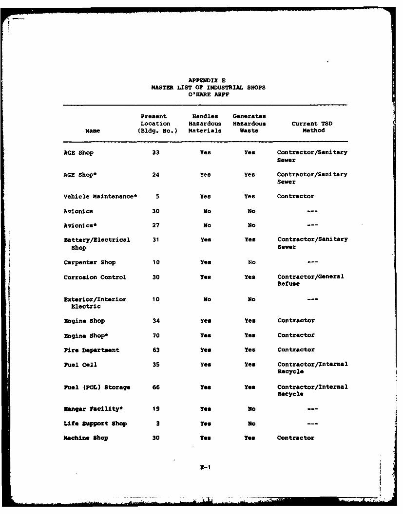
APPENDIX EMASTER LIST OF INDUSTRIAL SHOPS
O'HARE ARFF
Present Handles GeneratesLocation Hazardous Hazardous Current TSD
Name (Bldg. No.) Materials Waste Method
AGE Shop 33 Yes Yes Contractor/SanitarySewer
AGE Shop* 24 Yes Yes Contractor/SanitarySewer
Vehicle Maintenance* 5 Yes Yes Contractor
Avionics 30 No No ---
Avionics* 27 No No ---
Battery/Electrical 31 Yes Yes Contractor/SanitaryShop Sewer
Carpenter Shop 10 Yes No
Corrosion Control 30 Yes Yes Contractor/GeneralRefuse
Exterior/Interior 10 No No ---
Electric
Engine Shop 34 Yes Yes Contractor
Engine Shop* 70 Yes Yes Contractor
Fire Department 63 Yes Yes Contractor
Fuel Cell 35 Yes Yes Contractor/InternalRecycle
Fuel (POL) Storage 66 Yes Yes Contractor/InternalRecycle
Hangar Facility* 19 Yes No
Life Support Shop 3 Yes o ---
Machine Shop 30 Yes Yes Contractor
2-1
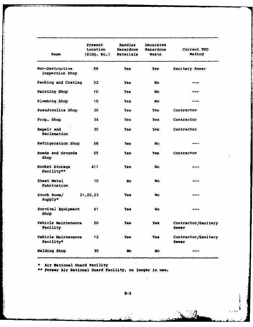
Present Handles Generates
Location Hazardous Hazardous Current TSDName (Bldg. No.) Materials Waste Method
Non-Destructive 59 Yes Yes Sanitary Sewer
Inspection Shop
Packing and Crating 32 Yes No ---
Painting Shop 10 Yes No
Plumbing Shop 10 Yes No ---
Pneudraulics Shop 30 Yes Yes Contractor
Prop. Shop 34 Yes Yes Contractor
Repair and 30 Yes Yes ContractorReclamation
Refrigeration Shop 58 Yes No ---
Roads and Grounds 55 Yes Yes ContractorShop
Rocket Storage 411 Yes NoFacility**
Sheet Metal 10 No NoFabrication
Stock Room/ 21,22,23 Yes NoSupply*
Survival Equipment 61 Yes NoShop
Vehicle Maintenance 50 Yes Yes Contractor/SanitaryFacility Sewer
Vehicle Maintenance 12 Yes Yes Contractor/SanitaryFacility* Sewer
Welding Shop 30 No No ---
* Air National Guard Facility
*' Former Air National Guard Facility, no longer in use.
2-2
kI.
APPENDIX F
PHOTOGRAPHS
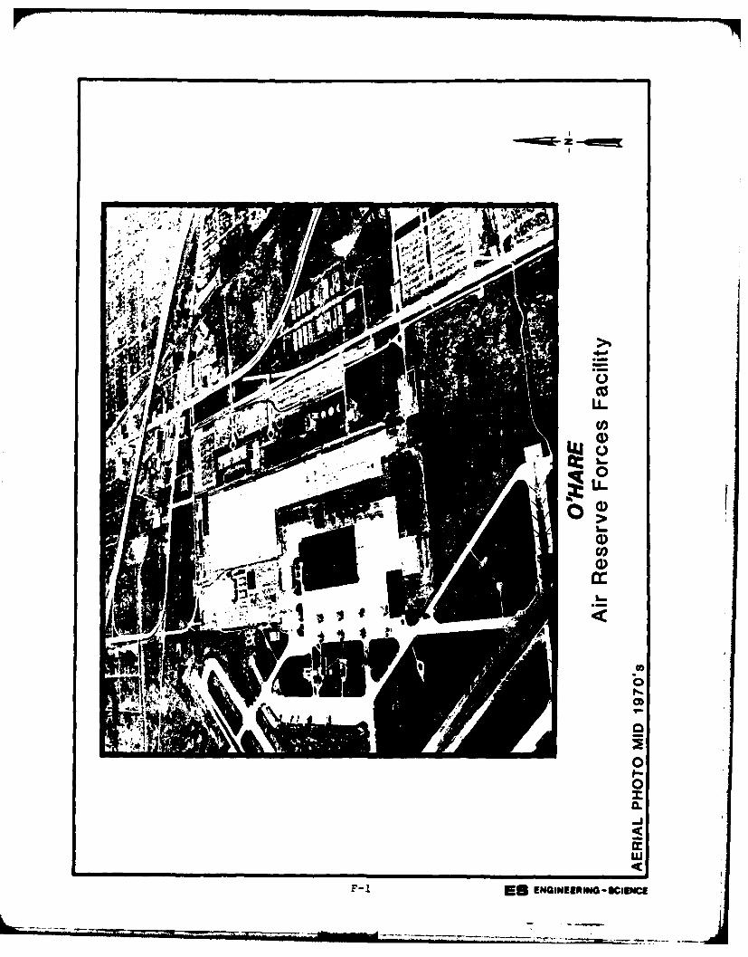
L ~LL
Cfu
Co
U)F-1 ENG~IERIGUSOE
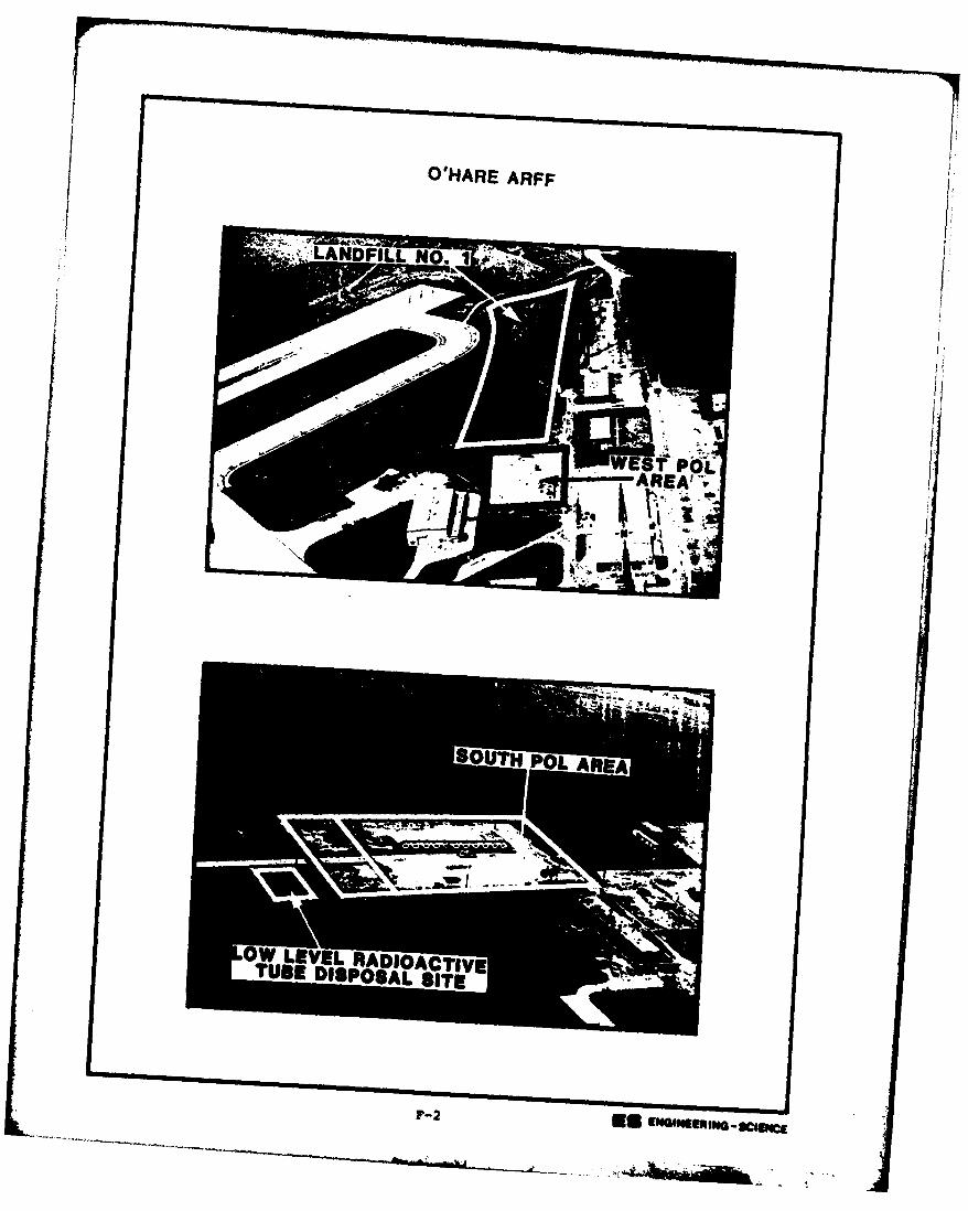
WHARE ARF
ND LLIiE~i'P''i,AREA'**I
OUT PL ARE
OWS LEVEL~ RAI ACTIVE
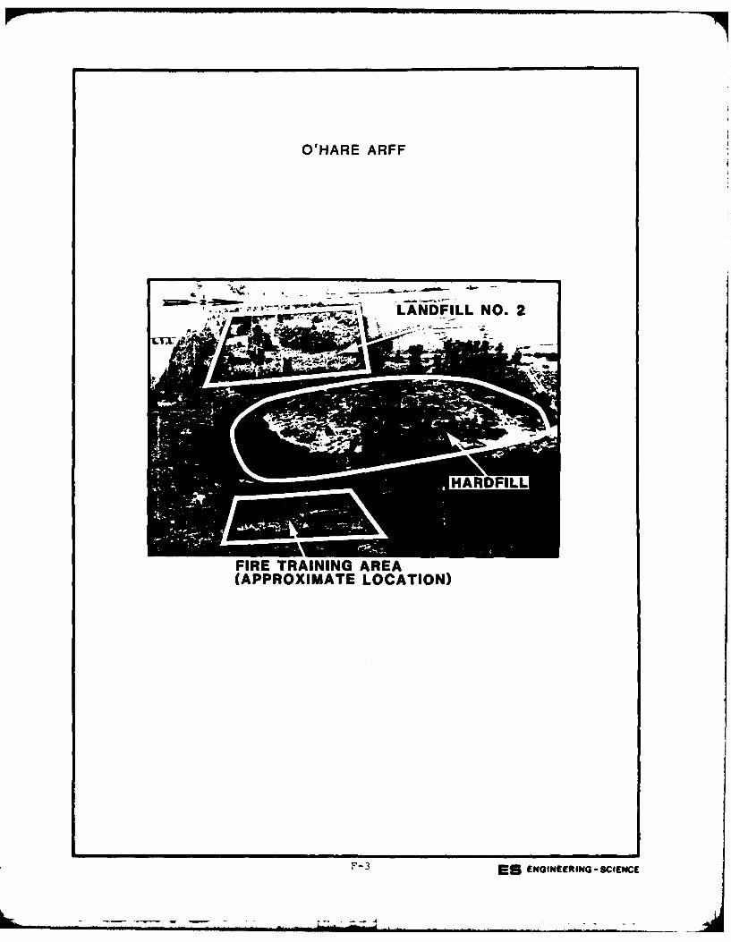
O'HARE ARFF
2 LANDFILL NO. 2
FIRE TRAINING AREA(APPROXIMATE LOCATION)
F-3 ES ENGINEERING -SCIENCE
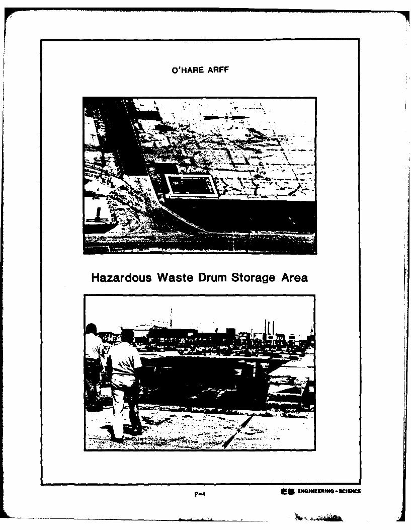
O'HARE ARFF
Hazardous Waste Drum Storage Area
F-4 EU NIEsIG3Ic
APPENDIX G
USAF INSTALLATION RESTORATION PROGRAM
HAZARD ASSESSMENT RATING METHODOLOGY
APPENDIX G
USAF INSTALLATION RESTORATION PROGRAM
HAZARD ASSESSMENT RATING METHODOLOGY
BACKGROUND
The Department of Defense (DOD) has established a comprehensive
program to identify, evaluate, and control problems associated with past
disposal practices at DOD facilities. One of the actions required under
this program is to:
"develop and maintain a priority listing of con-taminated installations and facilities for remedialaction based on potential hazard to public health,welfare, and environmental impacts." (Reference:
-DEQPPM 81-5, 11 December 1981).
Accordingly, the United States Air Force (USAF) has sought to establish
a system to set priorities for taking further actions at sites based
upon information gathered during the Records Search phase of its In-
stallation Restoration Program (IRP).
The first site rating model was developed in June 1981 at a meeting
with represenatives from USAF Occupational and Environmental Health
Laboratory (OEHL), Air Force Engineering and Services Center (AFESC),
Engineering-Science (ES) and CH2M Hill. The basis for this model was a
system developed for EPA by JRB Associates of McLean, Virginia. The JRB
model was modified to meet Air Force needs.
After using this model for 6 months at over 20 Air Force installa-
tions, certain inadequacies became apparent. Therefore, on January 26and 27, 1982, representatives of USAF OEHL, AFESC, various major com-
mands, Engineering-Science, and CH2M Hill met to address the inade-
quacies. The result of the meeting was a new site rating model designed
to present a better picture of the hazards posed by sites at Air Force
installations. The new rating model described in this presentation is
referred to as the Hazard Assessment Rating Methodology.
G-1
PURPOSE
The purpose of the site rating model is to provide a relative
ranking of sites of suspected contamination from hazardous substances.
This model will assist the Air Force in setting priorities for follow-on
site investigations and confirmation work under Phase II of the IRP.
This rating system is used only after it has been determined that
(1) potential for contamination exists (hazardous wastes present in
sufficient qtntity), and (2) potential for migration exists. A site
can be deleted from consideration for rating on either basis.
DESCRIPTION OF MODEL
Like the other hazardous waste site ranking models, the U.S. Air
Force's site rating model uses a scoring system to rank sites for
priority attention. However, in developing this model, the designers
incorporated some special features to meet specific DOD program needs.
The model uses data readily obtained during the Records Search
portion (Phase I) of the IRP. Scoring judgments and computations are
easily made. In assessing the hazards at a given site, the model
develops a score based on the most likely routes of contamination and
the worst hazards at the site. Sites are given low scores only if there
are clearly no hazards at the site. This approach meshes well with the
policy for evaluating and setting restrictions on excess DOD properties.
As with the previous model, this model considers four aspects of
the hazard posed by a specific site: the possible receptors of the
contamination, the waste and its characteristics, potential pathways for
waste contaminant migration, and any efforts to contain the contami-
nants. Each of these categories contains a number of rating factors
that are used in the overall hazard rating.
The receptors category rating is calculated by scoring each factor,
multiplying by a factor weighting constant and adding the weighted
scores to obtain a total category score.
G-2
The pathways category rating is based on evidence of contaminant
migration or an evaluation of the highest potential (worst case) for
contaminant migration along one of three pathways. If evidence of
contaminant migration exists, the category is given a subscore of 80 to
100 points. For indirect evidence, 80 points are assigned and for
direct evidence, 100 points are assigned. If no evidence is found, the
highest score among three possible routes is used. These routes are
surface water migration, flooding, and ground-water migration. Evalua-
tion of each route involves factors associated with the particular mi-
gration route. The three pathways are evaluated and the highest score
among all four of the potential scores is used.
The waste characteristics category is scored in three steps.
First, a point rating is assigned based on an assessment of the waste
quantity and the hazard (worst case) associated with the site. The
level of confidence in the information is also factored into the
assessment. Next, the score is multiplied by a waste persistence
factor, which acts to reduce the score if the waste is not very
persistent. Finally, the score is further modified by the physical
state of the waste. Liquid wastes receive the maximum score, while
scores for sludges and solids are reduced.
The scores for each of the three categories are then added together
and normalized to a maximum possible score of 100. Then the waste man-
agement practice category is scored. Sites at which there is no con-
tainment are not reduced in score. Scores for sites with limited con-
tainment can be reduced by 5 percent. If a site is contained and well
managed, its score can be reduced by 90 percent. The final site score
is calculated by applying the waste management practices category factor
to the sum of the scores for the other three categories.
G-3
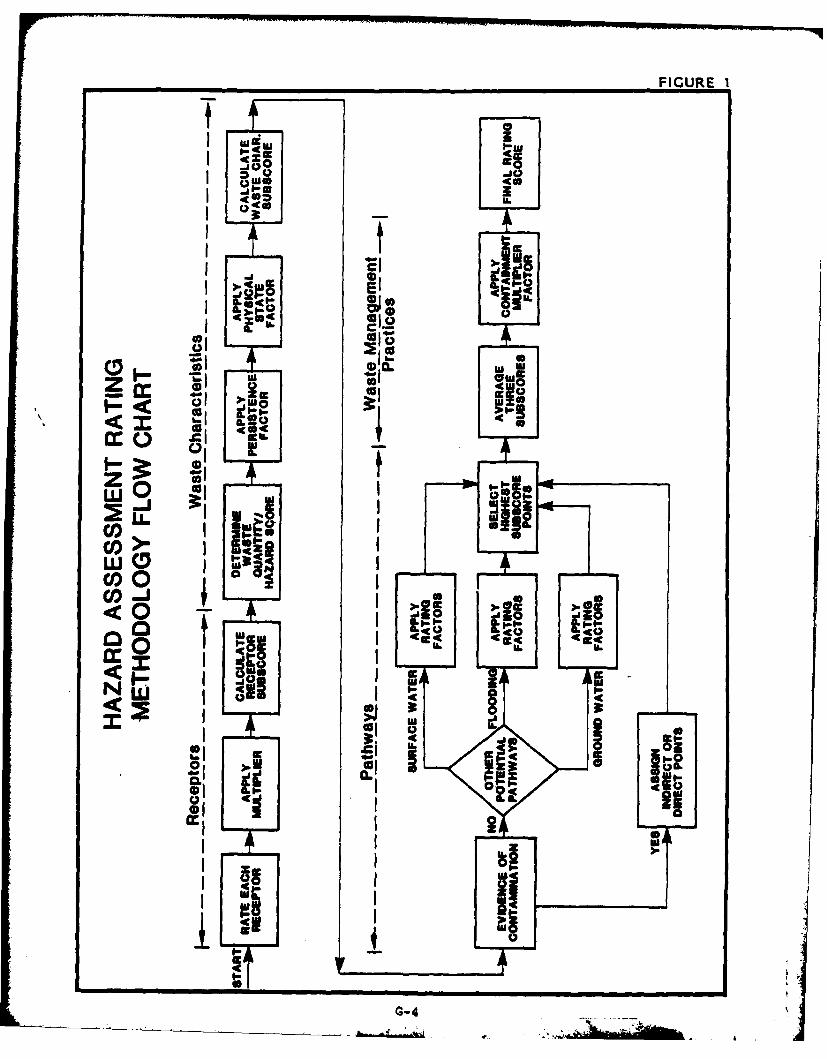
FIGURE I
UfI w -
I 4
I 12 . El
I'-1 Ol
0. 4c w- gg.
z
co0
ciodA
N W .4old
a 4-4
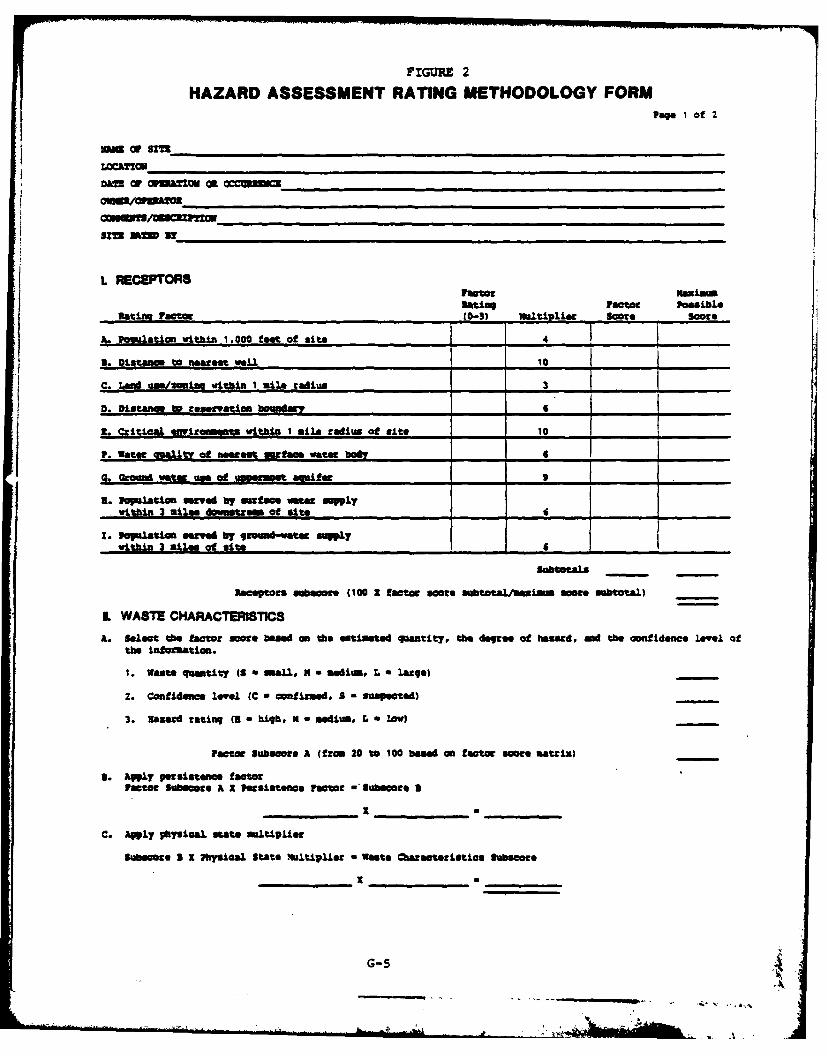
FIGURE 2
HAZARD ASSESSMENT RATING METHODOLOGY FORMPage 1 of 2
-gd O SITE'gacr smI
Un CaZ nnmCKocu
L RECEPTORSFactor maxilmltiag Factor Pouusble
Ratita. factor (0-3) ml00list Scott Score
A. Pomwlatin within 1.000 tfeet of mite 4_ _
S. Distance to neuat well 10 .
C. Lad ame/mfzw , within 1 silo tedium 3 -
U. Ditar nce to ervaian boundan' . 6 . ____ _____
L- Critical onmirnm a within I silo radius at site-10 ____ _____
P. Water quawt'y of nesta surfame water body 6
a. Groumendo utee am of &=s 9
a. lSelato served bre a ane emt
wthn 3atozaticm6
. pulation servd y (cr m-oed. saueyw.ithan Iatmies o it h 6
SubtataLs
F ectr o subaoo e (100 1 f(facm 20 s10 aose nf L 0 b n arm matoal)
IL WASTE CHARACTERU=SC
a. Select th fatr sMe based an the estmated quantit, the dogroo of hazard, and th confidence level oft~he infmton.
1. waste qeimbit y (f a tmalo l : 0 tedi. Z a .AM90)
2. Confidene level (C w cofi~rmed, 3 a suspected) --.-
3. earSd r~at:ling (I a high, K - misdiutm. L, a low?
/'ac-t.c Subscore A (from 20 to0 100 based an factor score umtrix )
aJ. Awply per:sistence fa~o1Pastor Suhmes: A 2 Persmtence factor -" lubsort a
C. Aply pbmical, state maultipue
Sub cot:e X MysiLcal State .altiple W at* Charateristics Subseore
G-5 4-~Al
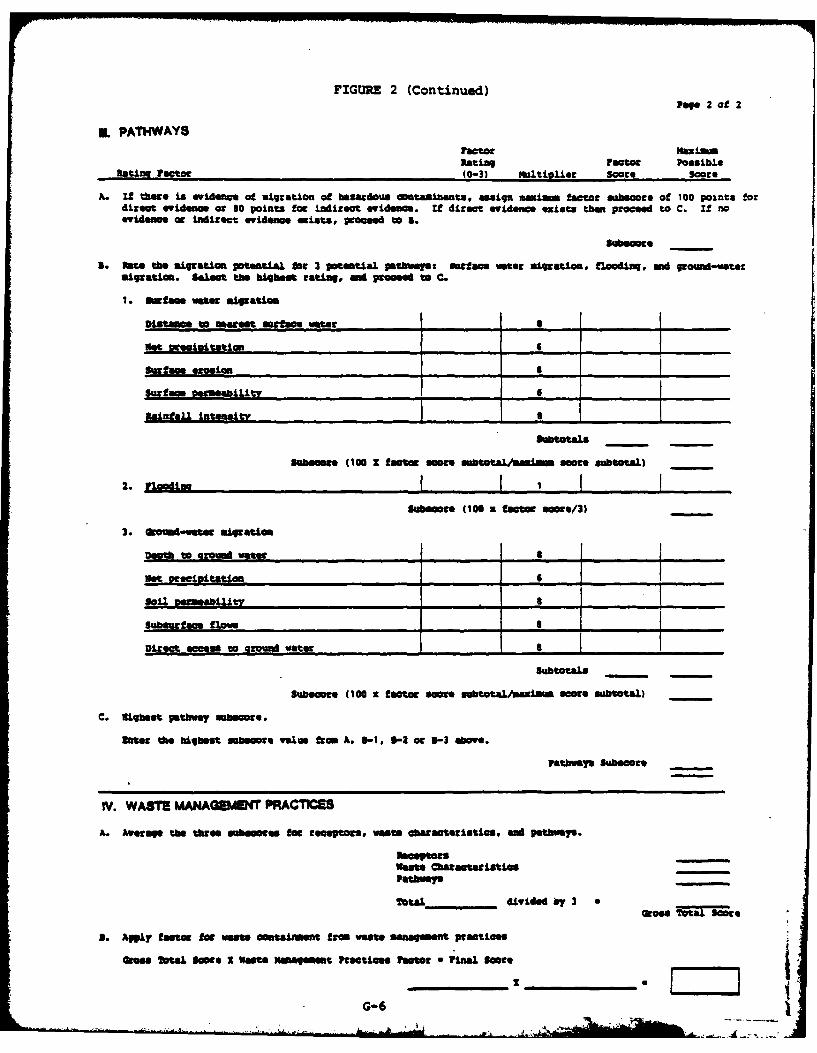
FIGURE 2 (Continued)Pege 2 of 2
IL PATHWAYStaPl r xftuxiw
Rating Factor PossibleRatiwn Factor (0-3) multiplier Score Score
A. If there is evidence o ugratoe o hasrdous comtaninants. assign aiimm factor mabucore of 100 points fordirect evidence o so points foe indizect evidenas. It direct evidence eists than proceed to C. if noevidence at indirect evideno. minrtse, poceed to a.
3. Vet the aigzatift potential Mag 3 potential p.thways surface water aigation, flooding, and ground-watataigratise. SeLeat the "iheft rating, md prese" to C.
1. Surfae wate Migration
Ditae u Waage" murface water . I
met Dtesioiltan ______ 6 _____ ____
Surfac e erosion 8
SWurae Decamne t
Subsere 0 00 1 lacter smeor .sttl- ~ soer subtotaL) -
2. Floedis I I I I IU*usor e (100 a fst r uae/3 -
3. Ovemt-wete aigratie
Domto Ground vater _
Net pceivtatlon ,6,
Subsurnface flows S
Direct access to around vater _
SubtotaLs
Subescor (100 x fast r s e sbttal/uaiam ustm. subtotal)
C. Nigbeat pathavy maocers.
fts: the highest subseore value rom , 1-1, 9-2 or *-3 aove.
Pathway% Suboore
IV. WASTE MANAEMENT PRACiMCES
)I Average the these sees lo rteswts waste aaseistiss, and pathvas.
maseptors-
Pate waras ite
Total.__ _ divided by 3 o
a. Wgply factor fo vaste ontaiment from vast management practices
aeags Total usce I Wst" Mnaement Practies Pestr a yinal $Mees _______
I li
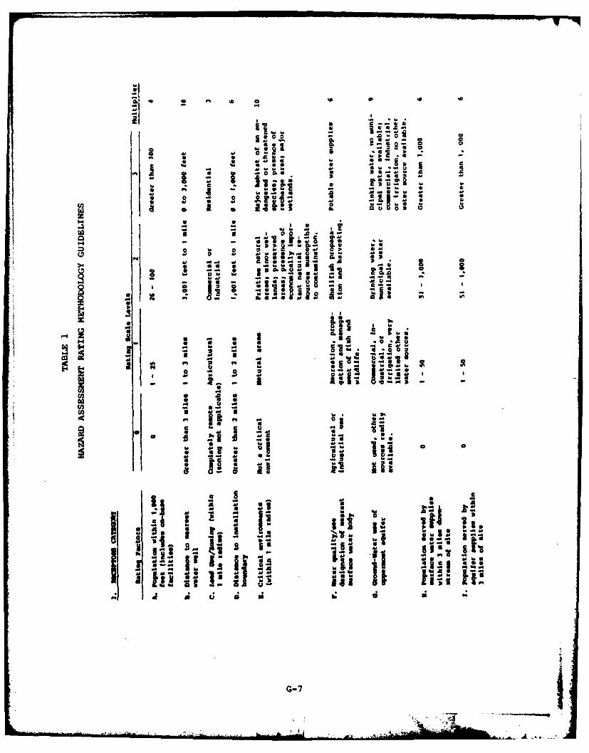
4 * 0 0t
- IC
A& Ta-li
USE o CImU2 Ai ~::i.~ -
4A 1.h. 6.
* - - -A -I
=~ w - I Od a
- G-7
* U . 0La8
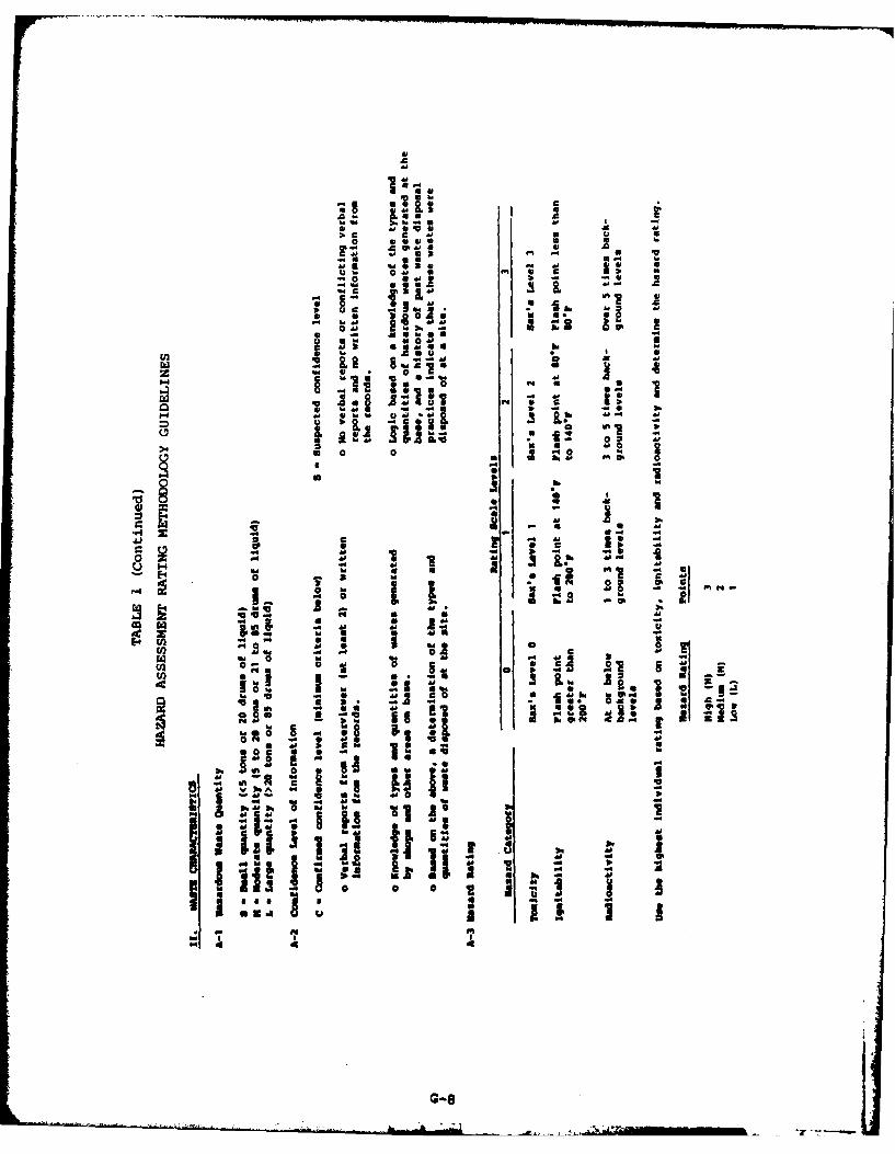
oi
v 31O IL 4 1
.1 1~ . - p I
U. 44
AA g
0 4'4
4
c* I
0 0 0 .
ad4
.31DI~l 4'44
0i 4' 0
I :
: ~ G--
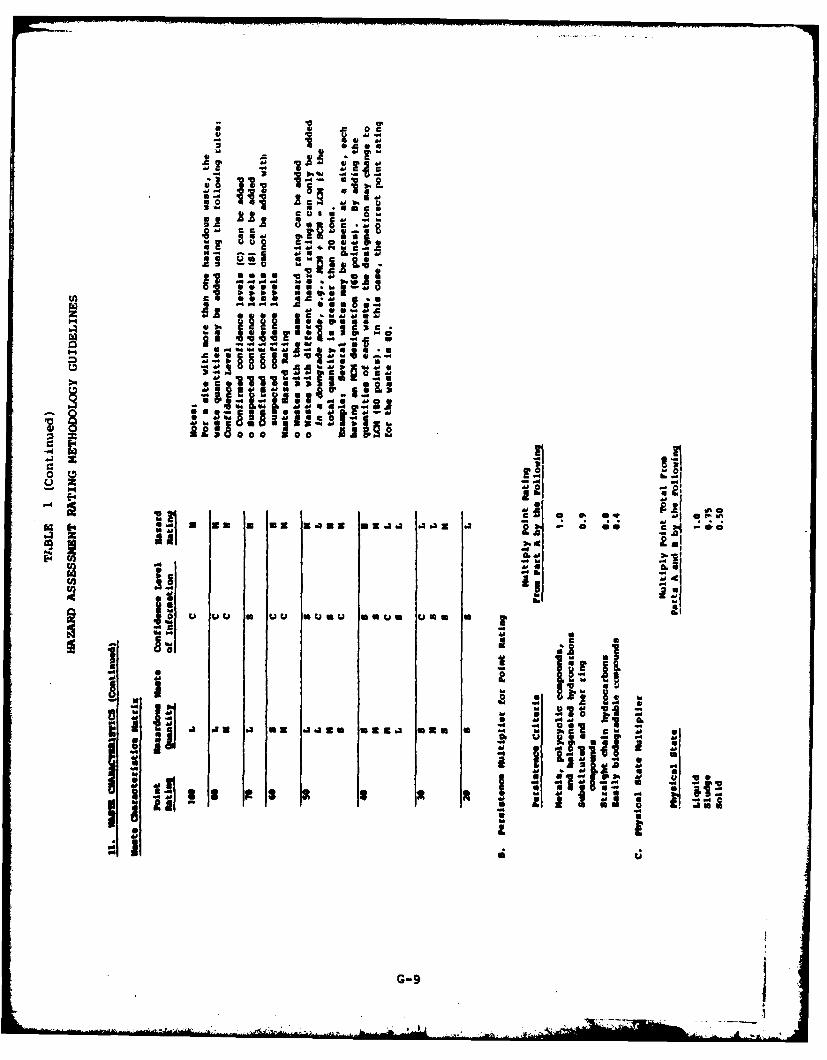
c 0 a.
.2 . '-
4 Aaa
a c Ao
.. 4M 400M_2
~4"
Zia ~ -m ox8.33m t .A 2C l ; 4a2 -- I
484
a. a~*MMoa
88 me epG-9
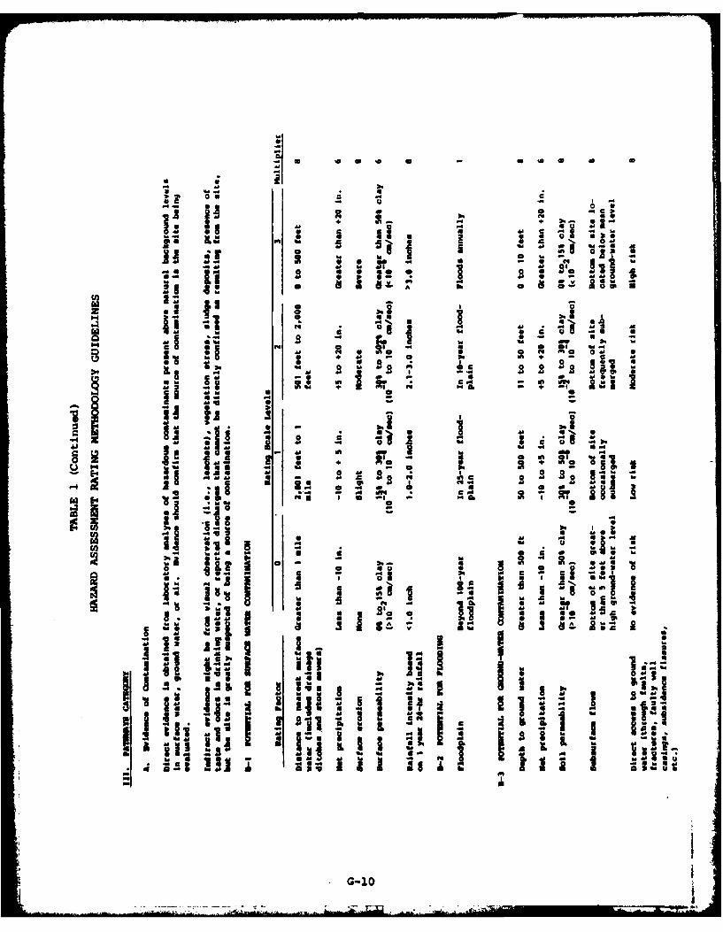
0 v
-0 so o s
0 A4 3. *0 U
fib za 0i 48 EU m
C4 ii F. M I"
ft * ~-4 48 * U M
hi a a led a j
- 4 sS all95 -mt ft a~
5 ~ A8*~~~~" me ml. I
I I M Sdo -
UPI .i 44S * *1
II II ii !~~ Gi i0

00
0.4
000
U) M4
4101
2 3M da
G-11
APPENDIX H
HAZARD ASSESSMENT RATING FORMS
J6_ _ _ _ _ _ _ _ _ _ I
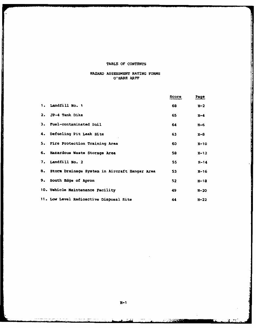
TABLE OF CONTENTS
HAZARD ASSESSMENT RATING FORMSO'HARE ARFF
Score Page
1. Landfill No. 1 68 H-2
2. JP-4 Tank Dike 65 H-4
3. Fuel-contaminated Soil 64 H-6
4. Defueling Pit Leak Site 63 H-8
5. Fire Protection Training Area 60 H-10
6. Hazardous Waste Storage Area 58 H-12
7. Landfill No. 2 55 H-14
S. Storm Drainage System in Aircraft Hangar Area 53 H-16
9. South Edge of Apron 52 H-18
10. Vehicle Maintenance Facility 49 H-20
11. Low Level Radioactive Disposal Site 44 H-22
H-I
S~-..-- C. |
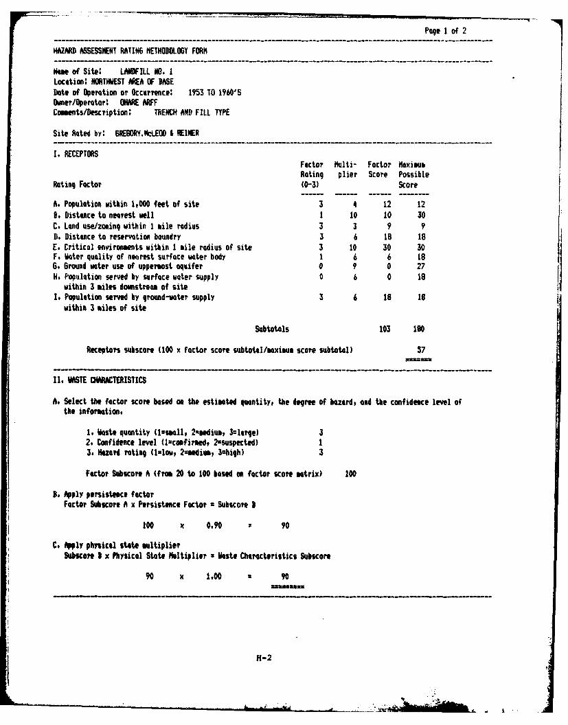
Page I of 2
HAZARD ASSESSMENT RATING NETHODOLOGY F0Rt
Ne of Site: LANDFILL NO. ILocation: NORTHWEST AREA OF BASEDate of Operation or Occurrence: 1953 TO 1960'SDwer/Operatorf OHARE ARFComents/Description: TRENCH AND FILL TYPE
Site Rated by: GR6ORY.NLEOD & REINER
I. RECEPTORSFactor Multi- Factor MaximouRating plier Score Possible
Rating Factor (0-3) Score
A. Population within 1,000 feet of site 3 4 12 12B. Distance to nearest well 1 10 10 30C. Land use/zoning within 1 mile radius 3 3 9 9D. Distance to reservation bowndry 3 6 18 18E. Critical environments within 1 mile radius of site 3 10 30 30F. 1ater quality of nearest surface water body 1 6 6 186. Ground vter use of uppermost aquifer 0 9 0 27H. Population served by surface water supply 0 6 0 18
within 3 miles downstream of siteI. Population served by ground-vater supply 3 6 18 18
within 3 iles of site
Subtotals 103 180
Receptors subscore (100 x factor score subtotal/maxium scare subtotal) 57
II. WASTE CHARACTERISTICS
At Select the factor score besed on the estimated quantity, the degree of bazerd, and the confidence level ofthe information.
1. Wste quantity (l=ssall, 2ediump, 3larqe) 32. Confidence level (1:cmifirmed, 2zsuspected) 13. Hazard rating (1=1ow, 2=sedivm, 3=hiqh) 3
Factor Subscore A (from 20 to 100 based on factor score matrix) 100
So Apply persistence factorFactor Subsucce A x Persistence Factor = Subscore B
100 x 0.90 : 90
C. Apply physical state multiplierSubscote I x Physical State Mltiplier W 1aste Characteristics Subscore
90 x 1,00 90
H-2
-IL
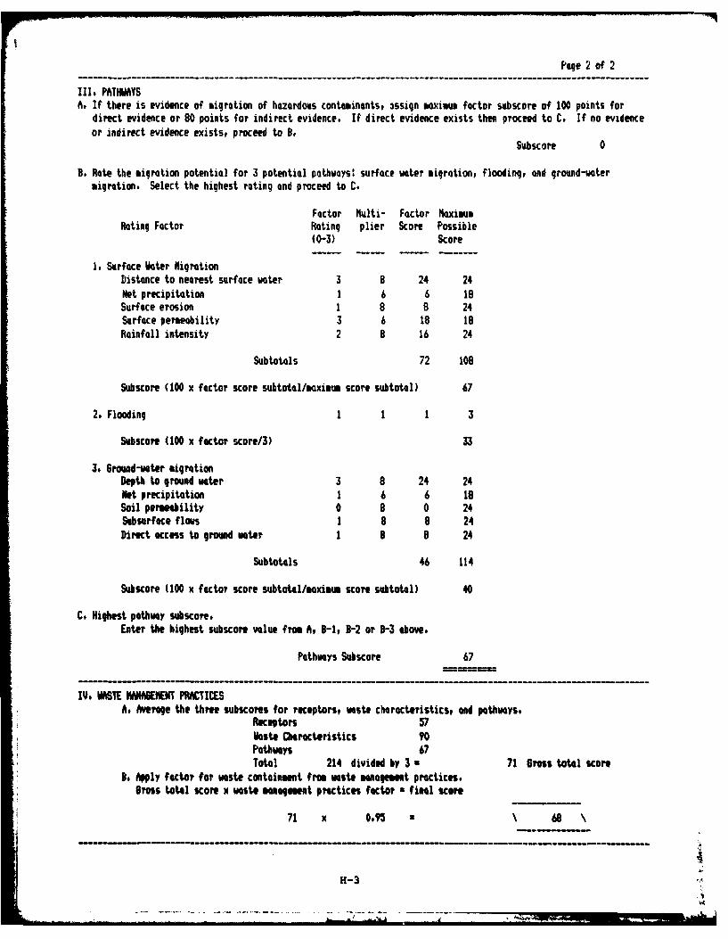
Page 2 of 2
III. PATHIMYSA. If there is evidence of migration of hazardous contaminants, 3ssign maximm factor subscore of 100 points for
direct evidence or 80 points for indirect evidence. If direct evidence exists then proceed to C. If no evidenceor indirect evidence exists, proceed to B.
Subscore 0
B. Rate the migration potential for 3 potential path ays: surface water migration, flooding, and ground-watermigration. Select the highest rating and proceed to C.
Factor Multi- Factor MaximumRating Factor Rating plier Score Possible
(0-3) Score
1. Surface Water MiqrationDistance to nearest surface water 3 8 24 24Net precipitation 1 6 6 18Surface erosion 1 8 8 24Surface permeability 3 6 18 18Rainfall intensity 2 8 16 24
Subtotals 72 108
Subscore (100 x factor score subtotal/mximum score subtotal) 67
2. Flooding 1 1 1 3
Subscore (100 x factor score/3) 33
3. Grawnd-vater igrationDepth to ground water 3 8 24 24Net precipitation 1 6 6 i8Soil permeability 0 8 0 24Subsurface flows 1 8 8 24Direct ccess to ground water 1 8 8 24
Subtotals 46 114
Subscore (100 x factor score subtotal/maximum score subtotal) 40
C. Highest pathway subcore.Enter the highest subcore value from A, B-19 -2 or 9-3 above.
Pathways Subscore 67
IV. WASTE NIANA6Et PRACTICESA. Averqe the three subscores for receptors, waste characteristics, and pathways,
Receptors 57Waste Characteristics 90Pathways 67Total 214 divided by 3 . 71 Gross total score
3, Aply factor for waste containment from waste management practices.Gross total score x wst menagment practices factor fimal score
71 x 0,95 68 \
H-3
7-)
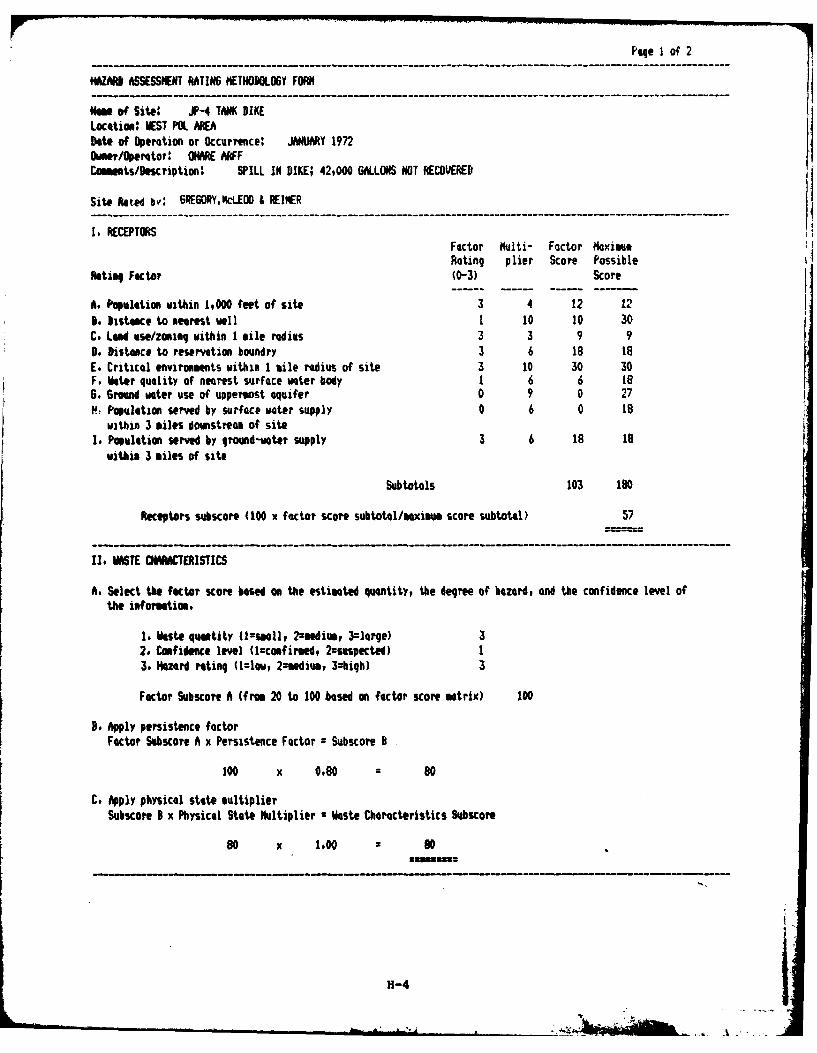
Page 1 of 2
AZARD ASSESSMENT RATING METHODOLOGY FORM
iM of Site: JP-4 TiNK DIKELocation: WEST POL AREA
Date of Operation or Occurrence: JANUARY 1972Oranr/Operetor: ONARE AAFFCommnts/Description' SPILL IN DIKE; 42#000 GALLONS NOT RECOVERED
Site kted bv: GRE6ORY,k.LEO & REINER
I. RECEPTORSFactor Multi- Factor MaximusRating plier Score Possible
Reting Factor (0-3) Score
A. Populetion within 1,000 feet of site 3 4 12 128. Distance to neareit well 1 10 10 30C. Led ase/zoning within 1 mile radius 3 3 9 9P. Distance to reservation boundry 3 6 18 18E. Critical environments within 1 tile radius of site 3 10 30 30F. later quality of nearest surface water body 1 6 6 186. Ground water use of uppermost aquifer 0 9 0 27P? Population served by surface water supply 0 6 0 18
within 3 miles downstream of siteI. Population served by ground-water supply 3 6 18 18
within 3 miles of site
Subtotals 103 180
Receptors subscore (100 x factor score subtotal/maximum score subtotal) 57
11. iST O"CTERISTICS
A. Select the fKtor score based on the estimated quantity, the degree of hazard, and the confidence level of
the infortatiom.
1. ikste qumtity (Isnll, 2=mediue, 3=large)2. Confidence level (l=confirmed, 2=rsuspected) I3. hazard rating (1zl=w, 2=%edium, 3=high) 3
Factor Subscore A (frm 20 to 100 .based on factor score matrix) 100
B. Apply persistence factorFactor Subscore A x Persistence Factor = Subscore 3
100 x 0.80 80
C. Apply physical state multiplierSubscore I x Physical State Multiplier • Waste Characteristics Subscore
80 x 1.00 = 80
H-4
A
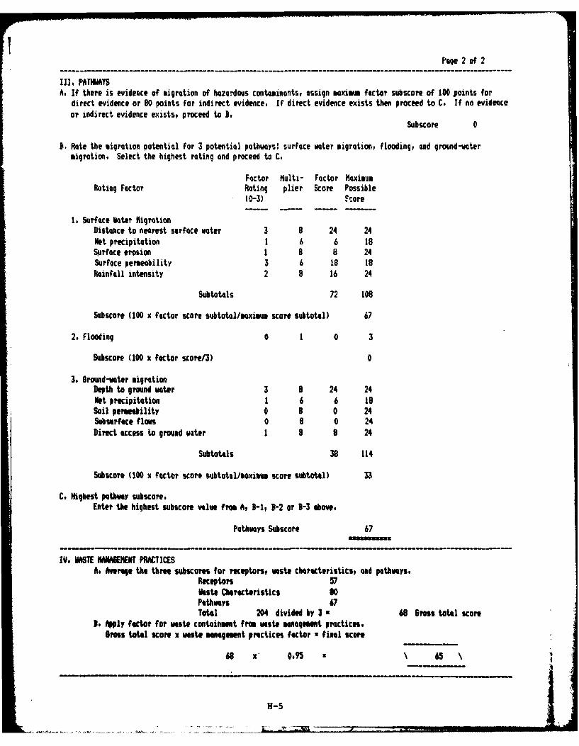
Page 2 of 2
III. PATHIAYSA. If there is evidence of migration of hazardous contaminonts, assign maxima factor subscore of 100 points for
direct evidence or 80 points for indirect evidence. If direct evidence exists then proceed to C. If no evidenceor indirect evidence exists, proceed to B.
Subscore 0
B. Rate the migration potential for 3 potential pathways: surface water migration, flooding, and ground-watermigration. Select the highest rating and proceed to C.
Factor hulti- Factor NoxiusRating Factor Rating plier Score Possible
(0-3) Ftore
1. Surface Water hiqrtionDistance to nearest surface water 3 8 24 24Net precipitation 1 6 6 18Surface erosion 1 8 8 24Surface permeability 3 6 18 18Rainfall intensity 2 8 16 24
Subtotals 72 108
Subscore (100 x factor score subtotal/maxim score subtotal) 67
2. Flooding 0 1 0 3
Subscore (100 x factor score/3) 0
3. Ground-water migrationDepth to ground water 3 8 24 24Net precipitation 1 6 6 18Soil permeability 0 8 0 24Subsurface flows 0 8 0 24Direct access to ground water 1 8 8 24
SubtotAls 38 114
Subscore (100 x factor score subtotal/saxim score subtotal) 33
C. Highest pathway subscore.Enter the highest subscore value from A, B-1, B-2 or B-3 above,
Pathways SubscAre 67
IV. WSTE HANABEMENT PRACTICESA. Average the three subscores for receptors, waste cheracteristics, and pathways,
Receptors 57iste Characteristics 80Pathways 67Total 204 divided by 3 • 68 Gross tofl score
f Apply factor for waste cont4inment from waste managemt practices,Brss total score x vste management practices factor • final score
68 x' 0.95 • 65
H-5
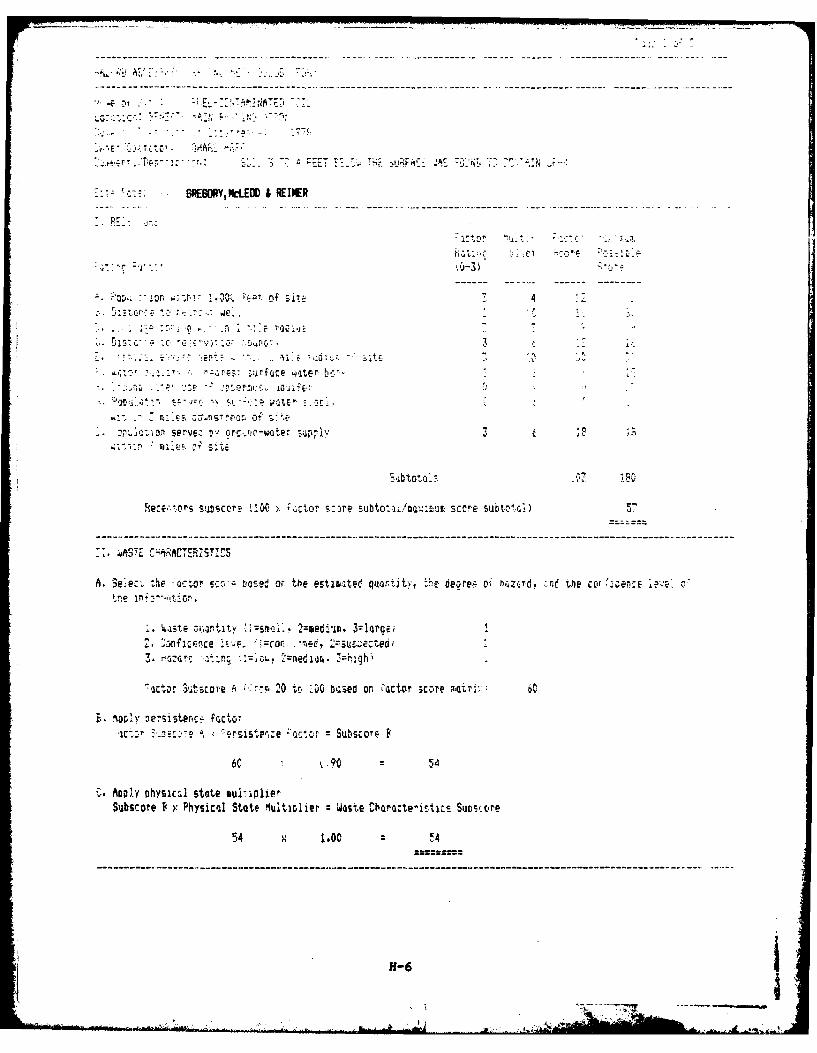
f--l -- - -~ - -MA'-
BRESDRYN.E D & REINER
... or
0'3. on. ii - 0 ",-t ofj 4T. ncir, -: 7. - -
1 -- '.. .
j:r-faCe water bcr-4
. n 9 Li on ser e, tv o .: . ' :,. ". - w te skip,"
- I, .v
S'btoto> 3-?_, .ThU
Rerert1ors subscore 1,10 :uctor s -re sut~~~<etscore Subtot-i) ST
A. Seie t the -actor Lao- sed or the estimaited. qurtity, .h. deoree o: bZ,rd, -n the cor %CCE aY. 0
1, a_;tse ,,,ntity ism,.i:, 2=medim, 3:lare;*5ffliCfCEc LiE. =car. -. C, ( U c t. e3, : r, . n .=,,-, 2zmediian%, 7-:h '
,actor ubscore A .>. 20 to 100 t-csed or :actor scoire F Uri;:: 60
L. ol) nersistencs fnct.,
.-, .m-. A. rstsr:e -act*or SubsOore F
6C : .O 54
C. Applyf physical state mul-1lierSubscore D x Physical State luilniier z Waste Chracte-istics Suoscc're
54 x 1.00 :4
..... . . - .. - ' _ ;_ 'T -:ti' 7 " ,,.
J - ,_ _ . ,, .a :, : .. . .,. .i " , ' ,',z . . : . 1.z. ,
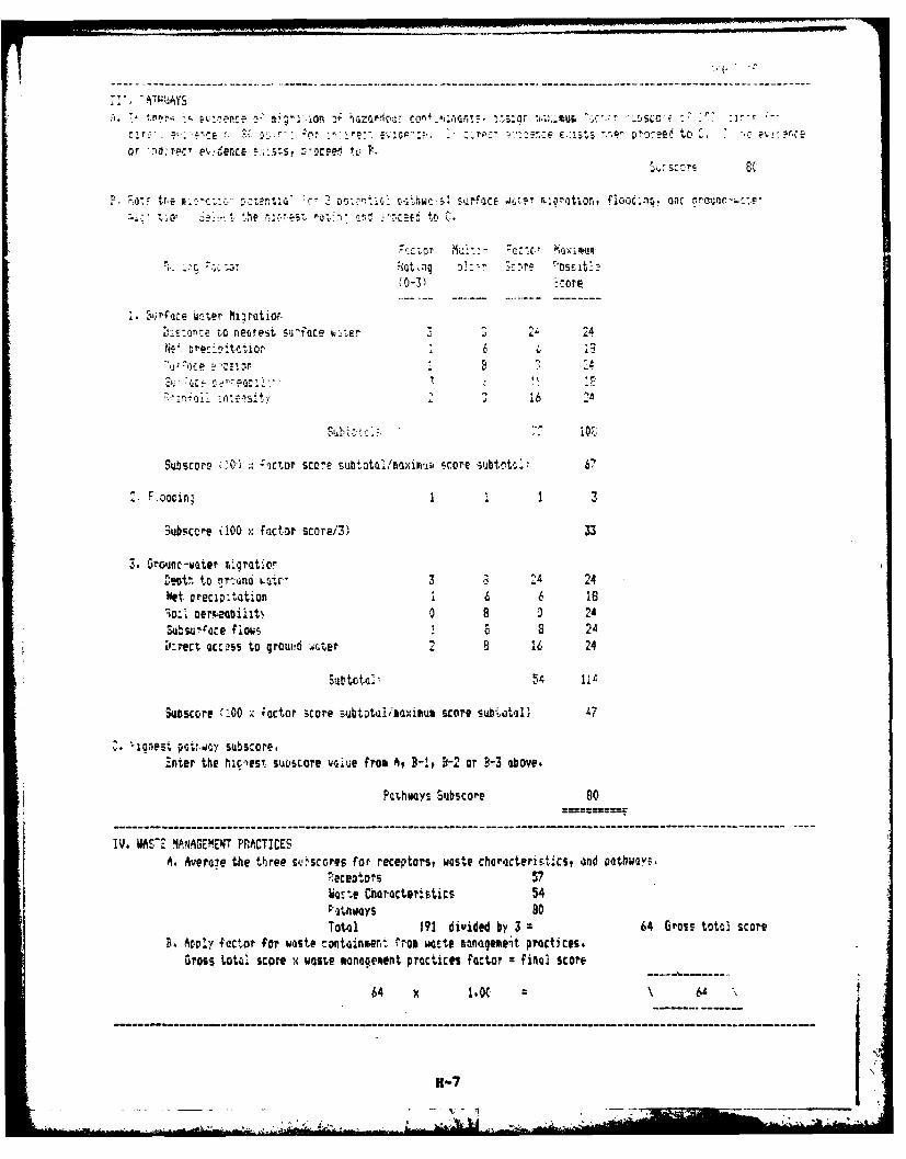
or ;rec- P,,, denLE _,ls -- cw t L'
P. ~v~trc ; 2-w~ I thwC5 s-irfoce k Iu.2rtio, fl-oc~np. On3 c
t ~ ~ ~ ; e. C.rEi 1~t: Nl 4CE ,CC
--,Ore
t~~reto reurest su'-oce w_-ter 2Ne,. Drec:_ tetior 13
Subscore '0 - -,Ctor SCo-e Siubtota t/mqXiIIt.p Srore Siubtt V
1 3
-lubscere (100 xfactor score13) 33
1.09t, to n'rt-jnd ,t 3 3 '24 24Net Preci;:tat'Aon £ 6 6 18;o:1 oermeabiiit . 0 8 0 2Subsutoce flows 8 )4
k'rect.~c~ to groud iroter 2 8 16 24
Subscore -:00 ;, ictor score subtotDaisaximum score subtotal, 47
-. ioPs;~ o subscore.Z:nter the hic.-est subsore voiue fro& A, B-It D-2 or Y-3 above.
Pathways Subscore 80
IV. WAS77 MAN.QEKINT PRlACTICESA, Averoue the three su.,scores for receptors, waste characteris.tics, and Othwl2yF.
ece~ors 57ksle Characteristics 54PFItway5 80Total 191 divided by 3 = 64 Gross totol score
B. Ar-py factor for waste contanmhert rroo woste management practices.Gross total score x waste moqement practices factor =final score
64 x 1.0( 6
- - - ~~H-? _ __ ,
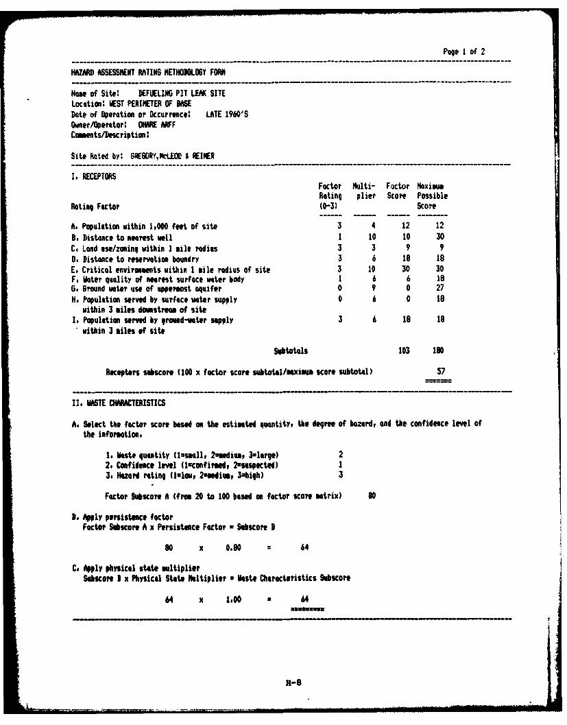
Page 1 of 2
HAZARD ASSESSMENT RATING METHODOLOGY FORM
Nam of Site: DEFUELIN6 PIT LEAK SITELocation: WEST PERIMETER OF BASEDate of Operation or Occurrence: LATE 1960'SOwer/Operator: OHARE ARFFComments/Description:
Site Rated by: GRE6ORY,ti.OD & RINER
I. RECEPTORSFactor Multi- Factor MaximmRating plier Score Possible
Rating Factor (0-3) Score
A. Population within 1,000 feet of site 3 4 12 12B. Distance to Nearest well 1 10 10 30C. Lend use/zoning within 1 mile radius 3 3 9 90. Distance to reservation boundry 3 6 18 18E. Critical environments within I mile radius of site 3 10 30 30F. Water quality of nearest surface water body 1 6 6 18G. Ground water use of uppermost aquifer 0 9 0 27H. Population served by surface water supply 0 6 0 18
within 3 miles downstream of siteI. Population served by gramd-water supply 3 6 18 18
within 3 miles of site
Subtotals 103 10
Receptors subscore (100 x factor score subtotal/maximum score subtotal) 57
I. ASTE CHARACTERISTICS
A. Select the factor score based on the estimated quantity, the degree of hazardt and the confidence level ofthe information,
1. Waste quantity (iimall, 2amedim, 3-large) 22. Confidence level (lconfirmed, 2uS§spKted) I3. Hazard rating Ullou, 2amedim, 3xhigh) 3
Factor Subscore A (froe 20 to 100 based on factor score matrix) 80
B. Apply persistence factorFactor Sbscore A x Persistence Factor z Subscore B
90 x 0.80 - 64
C, Apply physical state multiplierSubcore, I x Physical State Multiplier a aste Characteristics Sobscore
64 x 1.00 64
7 H-S
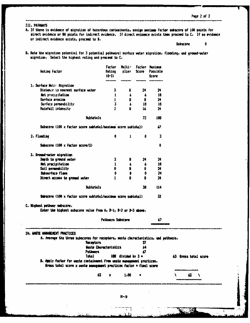
Page 2 of 2
11I. PATHIMYSA. If there is evidence of migration of hazardous containants, assign mxim faCtor subicore of 100 points for
direct evidence or 80 points for indirect evidence. If direct evidence exists then proceed to C. If no evidenceor indirect evidence exists, proceed to 3.
Subscore 0
3. Rate the migration potential for 3 potential pathwoys: surface water migration, flooding, and ground-watermigration. Select the highest rating and proceed to C.
Factor klti- Factor HaxisumRating Factor Rating plier Score Possible
(0-3) Score
1 Surface kt : ligrationDistant, to nearest surface water 3 8 24 24Net precipitation 1 6 6 18Surface erosion 1 8 8 24Surface permebility 3 6 18 18Rainfall intensity 2 8 16 24
SubtotAls 72 106
Subscore (100 x factor score subtotal/moximum score subtotal) 67
2. Flooding 0 1 0 3
Subscore (100 x factor score/3) 0
3. 6roud-vater migrationDepth to ground water 3 8 24 24Net precipitation 1 6 6 18Soil permeability 0 8 0 24SuSOrface floes 0 8 0 24Direct cess to grnd woter 1 8 8 24
Subtotals 38 114
hhscore (100 x factor score subtotal/mximm score subtotal) 33
C. Highest pathway sbscore.Enter the highest subscore value from A, I-I, 8-2 or -3 Above.
Pathways Subiore 67
IV. HASTE IWMENENT PRACTICESA. Average the three subscom for receptors, waste charecteristics, ad pathways,
Receptors 57Haste Charcteristics 64Pathways 67Total IN divided by 3 n 63 Bross total score
o. Apply factor for waste containment from wate mnament practices.•rosS total score x waste mn ment practices factor • final scor
63 x 100 63
H-9
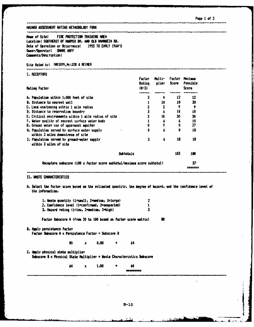
Pege I of 2
HAZARD ASSESSMENT RATIN METHODOLOGY FORM
Nome of Site: FIRE PROTECTION TRAININ AREALacation: SOUTEAST OF HPE DR. MD OLD HMNNEIM RD,Date of Operation or Occurrence: 1955 TO EARLY 1960'SOwner/Operator: OWMRE RFFCamments/Descriptia:
Site Rated by: GRE6ORY,NCLEOD i REINER
I. RECEPTORSFector Multi- Factor MaximumRating plier Score Possible
Rating Factor (0-3) Score
A. Population within 1,000 feet of site 3 4 12 12B, Distance to nearest well 1 10 10 30C. Land use/zoning within I mile radius 3 3 9 9D# Distance to reservation boundry 3 6 18 18E. Critical environments within 1 mile radius of site 3 10 30 30F, Water quality of nearest surface water body 1 6 6 18G. Ground water use of uppermost aquifer 0 9 0 27H. Population served by surface water supply 0 6 0 l8
within 3 miles downstream of siteI. Population served by ground-water supply 3 6 is 19
within 3 miles of site
Subtotals 103 190
Receptors subscore (100 x factor score subtotel/maximae score subtotal) 57
11. WSTE CHRATERISTICS
A. Select the factor score based on the estimated quantity, the degree of hazard, and the confidence level ofthe information.
1. Waste quantity (l-uall, 2-medium, 3-lerge) 22. Confidence level (l=confiwd, 2=-suspected) I3. Hazard rating (1=low, 2xuediv, 3zhigh) 3
Factor Subicore A (fro 20 to 100 based on factor score matrix) 80
3. Apply persistence factorFactor SbKor A x Persistence Factor = Subscore B
80 x 080 * 64
C. Apply physical state multiplierSubscore I x Physical State Multiplier • Waste Characteristics Subscore
64 x 1.00 • 64
H-10
....... .. ,
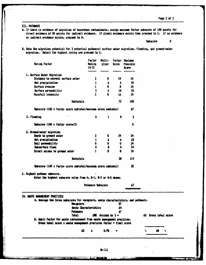
Pae.? of 2
III, PATHWAYSA. If there is evidence of migration of hazardous contaminatS, assign maxiM factor SUWiONe Of 100 points for
direct evidece of 80 points for indirect evidence. If direct evidence exists then proceed to C. If no evideaceor indirect evidence exists, proceed to B.
Subicore 0
Do Rate the migration potential for 3 potential pathways? surface water migration, flooding, and ground-watermigration. Select the highest rating and proceed to C.
Factor Mlti- Factor RaximumRating Factor Plating plier Score Possible
(0-3) Score
1. Surface Mater Rig rationDistance to nearest surface voter 3 3 24 24Net precipitation 1 6 6 18Surface erosion I a 8 24Surface Permeability 3 6 Is 18Rainfall intensity 2 9 16 24
Subtotals 72 106
Subicore (100 X factor sKore subtotl/aXim scoO subtotal) 67
2, Flooding 0 1 0 3
ubuore (10 X factor sore/3) 0
3. Groud-vater migrationDepth to ground water 3 8 24 24Net precipitation 1 6 6 16Soil pemmebility 0 8 0 24Subsurface, flows 0 6 0 24Direct access to growd voter 1 8 8 24
Subtotals 36 114
SubsCOre (100 X factor score subtoal/aim score sbtotal) 33
C. Highest pathwy subsore.EAtr the highest ubicore value fros A, H -1 -2 or D-3 above,
Pathways Subscore 67
IV, HAMT IWUSNENT PRACICESAt Average, the thre subicom for receptors, waste characteristics, ad pathways,
Receptors 57Naste Characteristics 64Pathway 67Totai 10 divided by 3 a63 Gross total Score
is ApiV factor for waste centaiDM t fM rem asmnam ent Practices.rass total Score X wast manaemet praiceIs factor *final score
63 x 0 *6
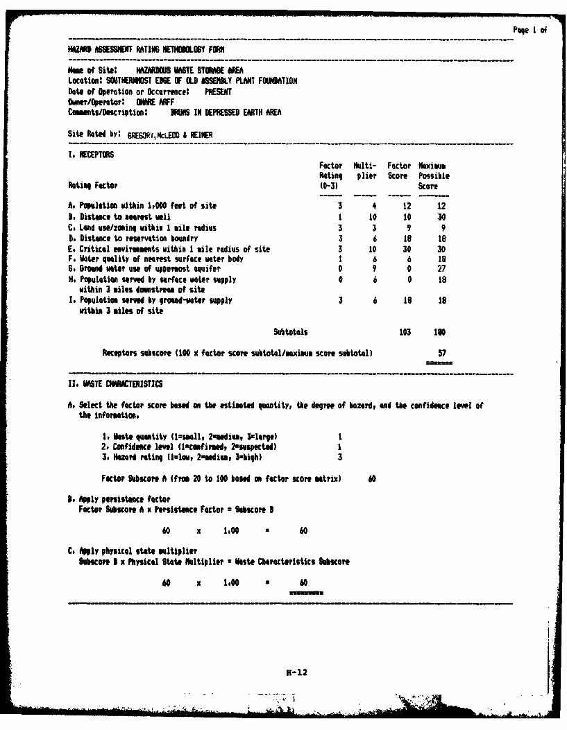
Page of
HAZARD ASSESSMENT MTIN6 NETHUHOOY FORM
MGs of Site: HAZARIOUS VASTE STOMGE NIOALocation SOUTHERIOST EME OF OLD &SEMM.Y PLANT FOUNDATIONDate of (peration or Occurrice: PRESENT0wnr/peotor: ON ARFComients/Description: MRS IN DEPRESSED EARTH AREA
Site Rated by: 6REORycCLEOD j REIER
1. RECEPTORSFactor Multi- Factor Maximu
Rating plier Score PossibleRatiug Factor (0-3) Score
A. populatim within IOO0 feet of site 3 4 12 123. Distance to amrost well 1 10 10 30C. Land use/zouing within 1 mile radius 3 3 9 90. Distance to reservation bowndry 3 6 18 18E. Critical envirumments within I mile radius of site 3 10 30 30F. Water quality of nearest surface water body 1 6 6 186. Ground voter use of uppermost aquifer 0 9 0 27H. Population served by surface water supply 0 6 0 18
within 3 miles downstream of siteI. Population served by ground-vater supply 3 6 19 18
within 3 miles of site
Subtotals 103 190
Receptors subscoe (100 x factor score subtotl/maximum score subtotal) 57
IIo WASTE CIHRACTERISTICS
A. Select the factor score based on the estimated quantity, the degree of hazard, and the confidnce level ofthe information,
1. este quantity (ssmllp 2-medium, 3clorge) 12. Confidence level (lcmfirmed, 2zsuspected) 13. Hazard rating (1=lov, 2"iedim, 3high) 3
Factor Subscore A (fre 20 to 100 based on factor score matrix) 60
B Apply persistence factorFactor Subscore A x Persistence Factor = Subicore 1
60 x 1.00 60
C. Apply physical state multiplierSubacore I x Physical State Mltiplier a Wste Characteristics Sbscore
60 x 1,00 • 60
H-12
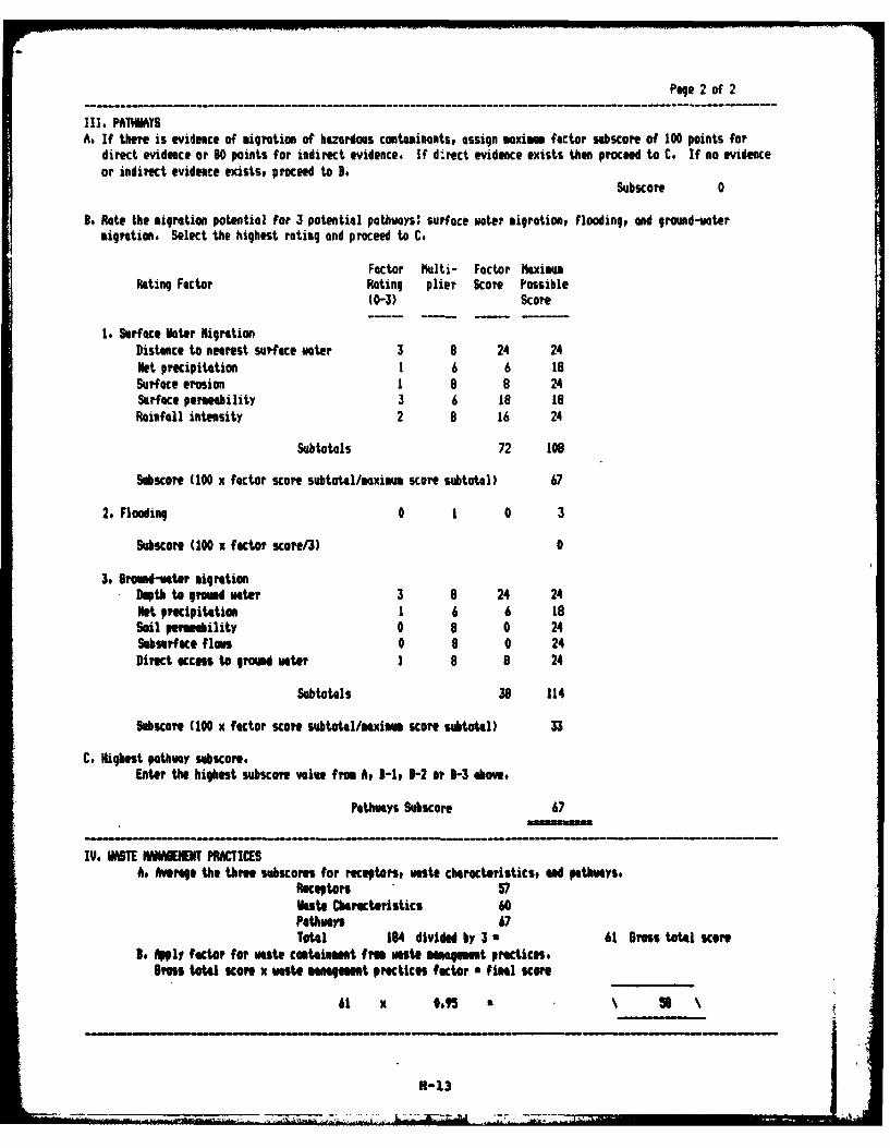
Pae 2 of 2
III, PATHWAYSA. If there is evidence of migration of hazardous contaminants, assign maximm factor subscore of 100 points for
direct evidence or 80 points for indirect evidence. If direct evidence exists then proceed to C. If no evidenceor indirect evidence exists, proceed to B.
Subscore 0
B. Rate the migration potential For 3 potential pathways: surface water igration, flooding, and ground-watermigration. Select the highest rating and proceed to C.
Factor Multi- Factor haximumRating Factor Rating plier Score Possible
(0-3) Score
1. Surface Water igrtionDistance to nearest surface vter 3 8 24 24Net precipitation 1 6 6 18Surface erosion 1 8 8 24Surface permeability 3 6 18 18Rainfall intensity 2 8 16 24
Subtotals 72 108
Subscore (100 x factor score subtotal/axim score subtotal) 67
2. Flooding 0 1 0 3
Suscore (100 x factor score/3) 0
3. 6od-ater migrationDepth to eomnd water 3 8 24 24Net precipitetim 1 6 6 18Soil permeility 0 8 0 24Subsurface floe 0 8 0 24Direct ccess to gromd water 1 8 8 24
Subtotals 38 114
Sobscore (100 x factor score subtotal/maximum score subtotal) 33
C, Highest pathway subscore.Enter the highest subscore value from A, 3-1, 3-2 or 3-3 above.
Pathways Subscore 67
IV. WASTE MANAICHENT PRACTICESA. Averaqe the three subscores for receptors, waste characteristics, ad pethmys.
Receptors 57Waste Charecteristics 60Pathways 67Total 184 divided by 3 a 61 Gross total score
3. Aply factor for Waste containment from waste mamgmt practices.Gross total score x vaste management practices fator • filS score
61 x *.S • H1
3-13
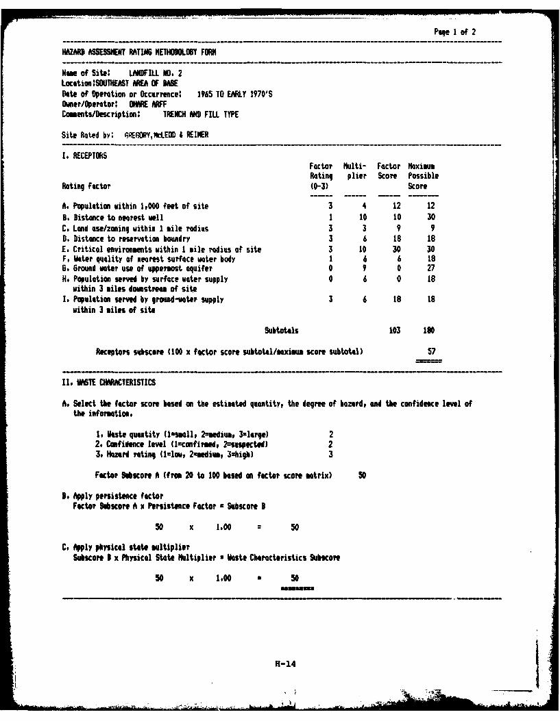
Page 1 of 2
HAZARD ASSESSMENT RATING METHODOLOGY FORN
Name of Site: LANDFILL NO, 2Location :SOUTHEAT ARE OF DASEDate of Operation or Occurrence: 1965 TO EARLY 1970'SOwner/Operator: OHARE ARFFCoumnts/Description: TRENCH AND FILL TYPE
Site Rated by: GEORY,M&CEOD I REINER
I. RECEPTORSFactor Multi- Factor MaximumRating plier Score Possible
Rating Factor (0-3) Score
A. Population within 1,000 feet of site 3 4 12 12B. Distance to nearest well 1 10 10 30C, Land use/zoning within I mile radius 3 3 9 9D. Distance to reservation boundry 3 6 18 i8E. Critical environments within I mile radius of site 3 10 30 30F. Wer quality of nearest surface water body 1 6 6 186. Ground water use of uppermost aquifer 0 9 0 27H# Population served by surface water supply 0 6 0 is
within 3 miles dowmitream of siteIt Population served by ground-water supply 3 6 18 1e
within 3 milts of site
Subtaols 103 10
Receptors subscore (100 x factor score subtotl/aximum scare subtotal) 57
11, WAS7E CHARACTERISTICS
A. Select the factor score based on the estimated quantityp the degree of bazard, and the confidence level ofthe information,
1. Wste quantity (isall, 2amediver 3zlarge) 22. Confidence level Uconfirmed, 2--SUsPetod) 23. Hazard rating (Irlow, 2asedim, 3shigh) 3
Factor Subeore A (from 20 to 100 based on factor score matrix) 50
be Apply persistence factorFactor 9ubscore A x Persistence Factor r Subscore B
so x 1.00 50
C. Apply physical state multiplierSubscore B X Physical State Multiplier a W1aste Characteristics Subscore
50 x 1.00 3 50
H-14
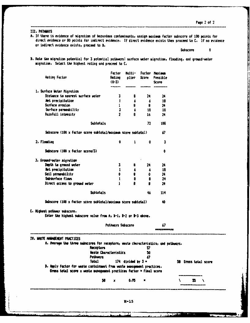
Page 2 of 2
Ill. PATHWAYSA. If there is evidence of migration of hazardous contaminants, assign maxim factor subscore of 100 points for
direct evidence or 80 points for indirect evidence. If direct evidence exists then proceed to C. If no evidenceor indirect evidence existst proceed to B.
Subscore 0
S. Rate the migration potential for 3 potential pathways: surface water igrationj flooding, and ground-wotermigration. Select the highest rating and proceed to C.
Factor Multi- Factor MaxiumRating Factor Rating plier Score Possible
(0-3) Score
1. Surface Voter MigrationDistance to nearest surface woter 3 8 24 24Net precipitation 1 6 6 19Surface erosion 1 8 8 24Surface permeability 3 6 18 18Rainfall intensity 2 8 16 24
Subtotals 72 108
Subscore (100 x factor score subtotal/saximm score subtotal) 67
2. Flooding 0 1 0 3
Sucore (100 x factor score/3) 0
3. Groud-voter migrationDepth to ground water 3 8 24 24Net precipitation 1 6 6 18Soil permeability 0 6 0 24Subsurface flows 1 8 8 24Direct access to ground woter 1 9 a 24
Subtotals 46 114
Subscore (100 x factor score subtotal/maxim score subtotal) 40
C. Highest pathway subscore.Enter the highest subscore value from 6, B-1, B-2 or V-3 above.
Pathways Subscore 67
IV. WASTE MANAGEMENT P8ACTICESA. Average the three subcores for receptors, waste characteristics, ad pathways.
Receptors 57vaste Characteristics 50Pathways 67Total 174 divided by 3 a 58 Gross total score
3, Apply factor for waste containment from waste magemt practices.Gross total score x wate managmeat practices factor • final score
5 x 0.95 • \ 5
H-1S
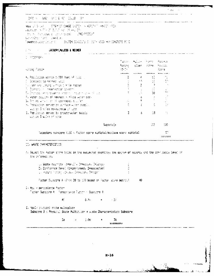
-- -- - - - - - - - - - -
* RE6ORY,MtLED &FEINER
*--- ----- --- -
A.~~~A. P n6;-,, W
IM -a .rr>t
-0
e Pi' n, D
Eectrs su-score !Z: '2~ cor-e subtotui/tCe.d'.u:4j SCo;re ;ubtotal
- wASTE£HACE'
- .Q4ste c L,:ttvy s Y.fe7 ;3 -: tc
Z CI csceJe'~.. (icor:rced,22susrected'
-ictor 3' 1scre *' 20 to 23b'asec or'co ic-re act::: 40
n1tor ,uotre--i~ A ,rsz ;i: s:*BD:-
Subecore B State Nult::.:e' v'e.te Char'ieteristi: Subsce
6 vv 36
H1-16
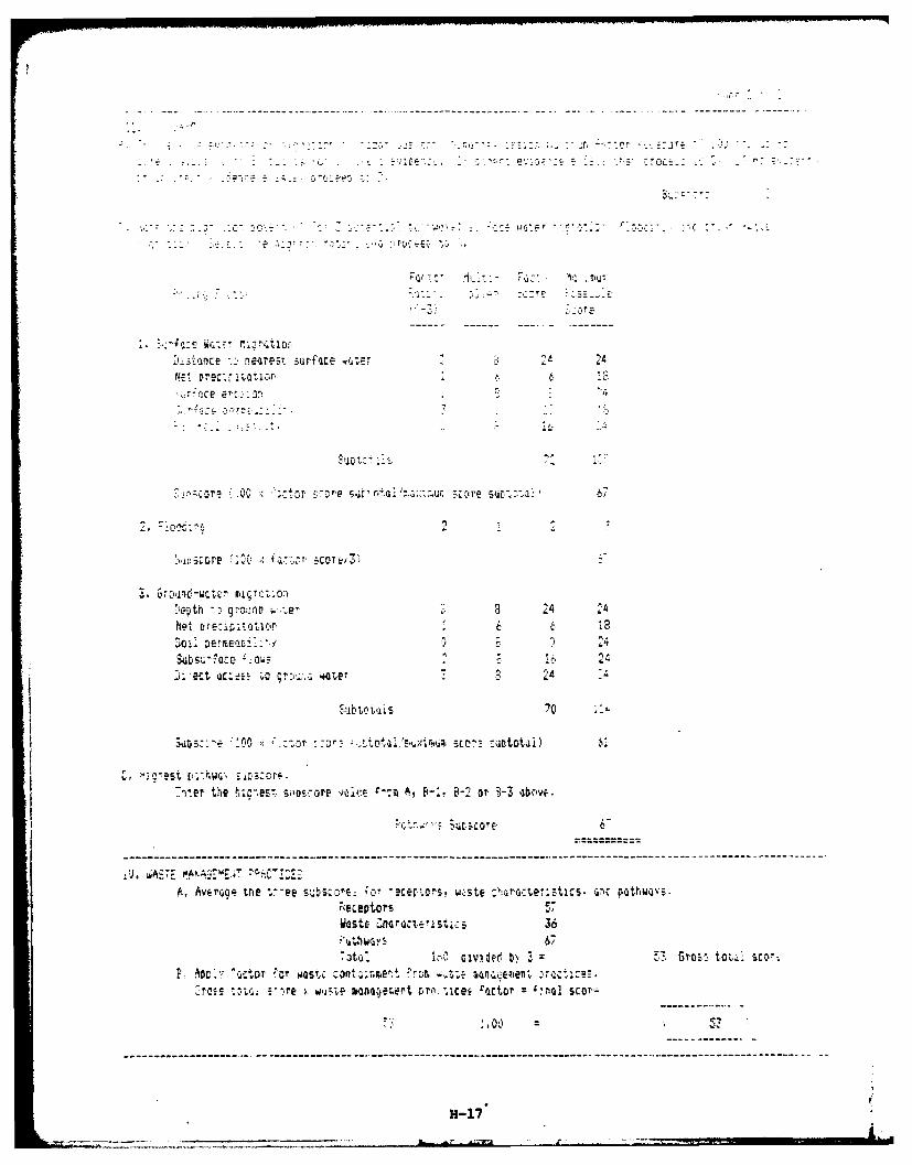
------ ~3 -- -- -- -- -
* I c ... e5 .- . . -
Ic er: -.n
2'
Net-hoi 70::ttl~
5~~ , -u l6
-,e h o rev (s -aA FA -2 orBa boe
:,:n-- fl-re-K-- 0$ Ct-- - -- - -- - -- - -- - -- ---tr- -- - ---re- - - ------- -- - - - -- - ---- - - -
Depthcepor gmuo i:8 4Netast 3~:ct~~r- 6 6
SUSt ~ divdee - -.z-o,,ti . c,
%£fo ubWST otov.n'is 70r' .in Qie
aUD;::e .0 i~r c, r ;. . totile..et >ur-.-.csmoto scot-:ooti
C. ~rst p*thw~ s~r;cr-enter ~ ~ ~ ~ ~ ~ ~ ~ ~ ~ ~ ----- th-~ts.smoe~ie~ ,B~ - r83oee
-- -- -- --- -- --- --- --- -- -- --- -- --- -- -- --- -- -- --- -- --- -- -- --- -- --- -- -- --- -- -
~H-1
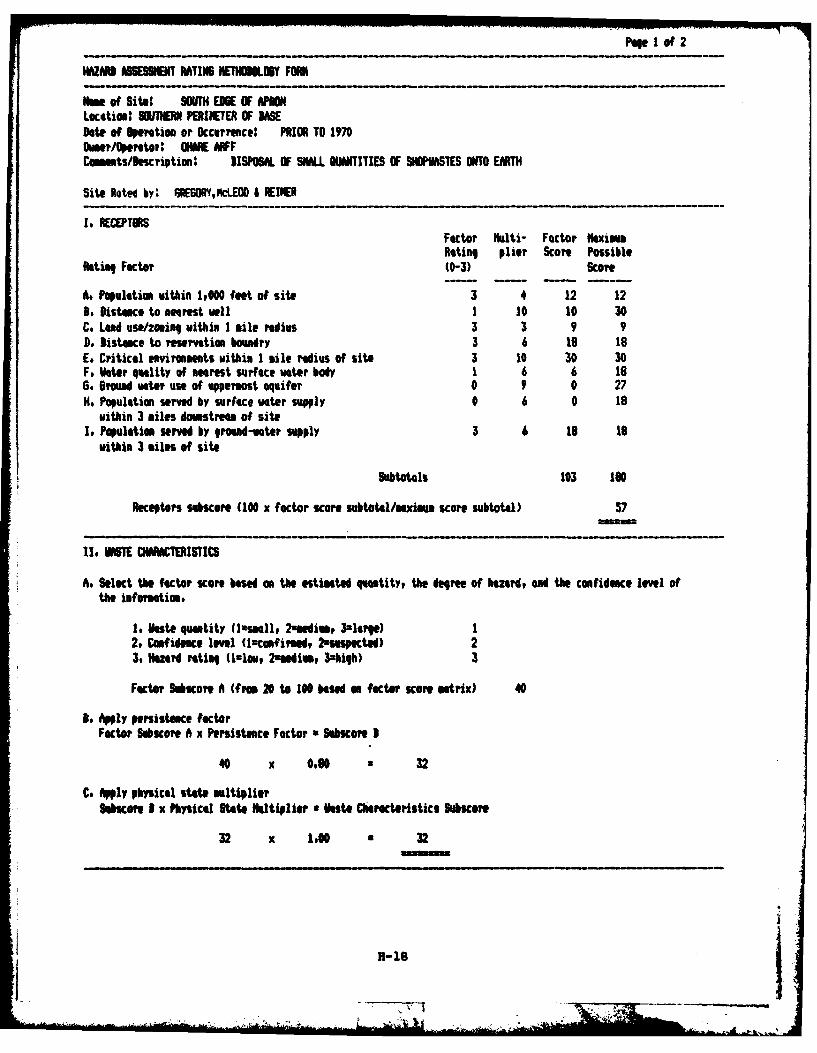
Page of 2
(lAS ASSESSENT RATIN6 HEM OY FORM
oe of Site: SOUN EDGE OFAMLocotiom SOUTHERN PERIMETER OF UASDate of Operatimn or Occurrence: PRIOR TO 1970Owmer/Operotor' INE AR FFCommts/Description" DISPOSAL OF SILL WNITIES OF SOPUASTES ONTO EM
Site Rated by: 6REBO6Y,kcLEO0 & EIIER
I, RECEPTORSFactor ulti- Factor MaximmRating plier Score Possible
Noting Factor (0-3) Score
A, Populatim ithin 1,000 feet of site 3 4 12 12, Distance to nearest well 1 10 10 30
C. Led use/zoning within 1 mile radius 3 3 9 9Do Distance to reservatimn bouadry 3 6 1e 18E, Critical environments within 1 mile radius of site 3 10 30 30F, 1ater quality of nearest surface water body 1 6 6 186, Sread mter use of uppermost aquifer 0 9 0 27He Population served by surface water supply 0 6 0 18
within 3 miles doastrea of siteIt Populatiom served by ground-water supply 3 6 19 18
within 3 miles of site
Subtotals 103 160
Receptors subscore (100 x factor score subtotal/maximum score subtotal) 57
IIt VASTE 01CRACTERISTICS
A. Select the factor score based on the estimated q atity, the degree of hazard, and the confidence level ofthe information.
1. Haste quantity (lasmll, 2-andim, 3zlege) 12, Confidence level (lconfirmed, 2uspected) 23. lazard rating (slou, 2andim, 3=high) 3
Factor hobscore A (from 20 to 100 based on factor score atrix) 40
3. Apply persistence factorFactor SubaKcoe A X Persistence Factor a Subscore I
40 x 0.0 32
C. Apply physical state mltiplierSobcoe I x Physical State Multiplier a Usto Characteristics Subscore
32 x 1.00 32
77
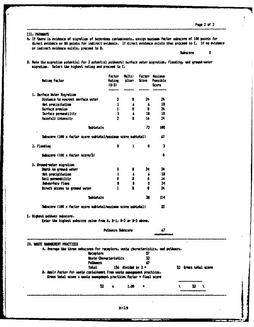
Paqe 2 of 2
Ill. PAIIMYSft It there is evidence of migration of Mzerdous contuinants, assign maxim factor subscore of 100 points for
direct evidence or 80 points for indirect evidence. If direct evidence exists then proceed to C. If no evidenceor indirect evidence existst proceed to B.
Subscore 0
I. Rlte the migration potential for 3 potential pothwys: surface water migration, flooding, ad ground-weteruiIretin. Select the highest rating and proceed to C.
Factor lklti- Factor kxiuRating Factor Rating plier Score Possible
(0-3) Score
1. Surface hter NigrationDistance to nearest surface enter 3 8 24 24Net precipitation 1 6 6 19Surface erosion 1 8 a 24Surface permebility 3 6 18 L8PRainfall intensity 2 8 16 24
Subtotals 72 106
SubScore (100 x factor score subtot4l/xim score subtotal) 67
2. Flooding 0 1 0 3
Sibscore (100 x factor score/3) 0
3. 6rond-vater migrationDephtogreund water 3 8 24 24Net precipitation 1 6 6 19Soil permeability 0 8 0 24Sburface flas 0 8 0 24Direct access to gromd vater 1 8 8 24
Subtotals 38 114
Sbscore (100 x factor score subtotl/mim score subtotal) 33
C. Highest pathway subscore.Eter the highest subiscore value from At 1-1t 3-2 or 3-3 sbove.
Pathways Subscore 67
IV, E NANAMMEIENT PRAT SA. Averae the three subcores for receptos, Waste cMract@istics, and pathwys.
Receptors 57Wkste Characteristics 32Pathwas 67
Totl 156 divided by 3 a 52 Gross total score3. Apply factor for vaste containent from ate management practices,
Gross totl score x veste mmmgmt practices factor a final score
52 N 1,00 52
H-'9
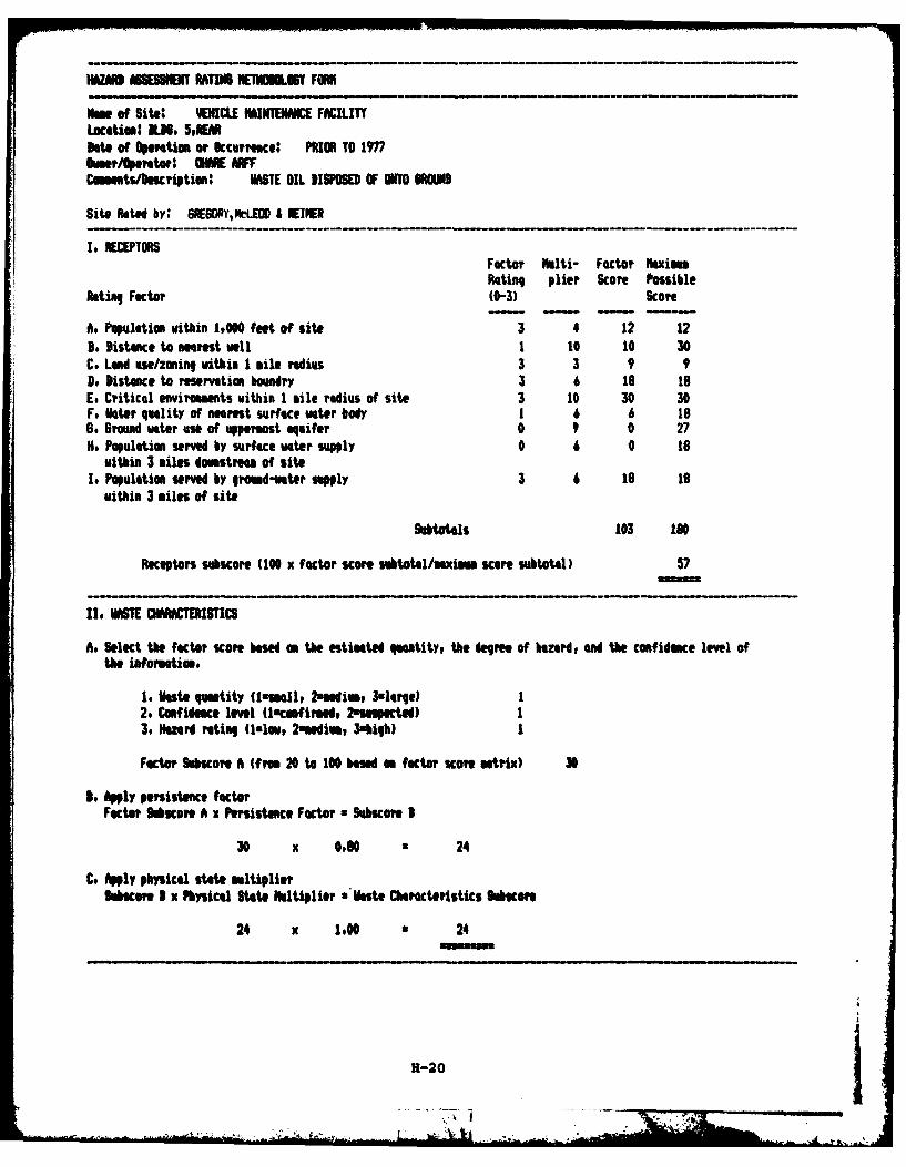
HAfiM ASESSIET RATING NENOLBt FOMN
Nam of Site: YOENCLE NMINTENNIC FACILITYLocation: N1.3, 5,REMDate of Operation or Sccurrence: PRIMR TO 1977Sumer/Operatorlo Mmii wvCommtstbescription' WASE OIL DISPOSED OF UNTO WOUND
Site Rated by: 6REG0PY,NckEO & WINER
I, RECEPTORSFactor Huiti- Factor haxiemRating plier Score Possible
Rating Factor (0-3) Score
A. Population within 1,000 feet of site 3 4 12 123. Disteace to nearest well I 10 10 30C. Land use/zoning within 1 mile radius 3 3 9 9D, Distance to reservation boundry 3 6 19 toE, Critical enviroments within 1 mile radius of sit. 3 10 30 30F. ilater quality of nearest surface water body 1 6 6 186. Groun mater use of uppermost aquifer 0 9 0 27He. Population served by surface water supply 0 6 0 t8
within 3 miles doutstream of siteIt Population served by graud-water supply 3 6 18 is
within 3 miles of site
Subtotals 103 lot
Receptors suahscore (100 x factor score subtotl/aximm score subtotal) 57
II 0A1ECARACTERISTICS
A. Select the factor score based on the estimated quatity, the degree of hazad, and the confidence lee ofthe information.
I. Vast@ quntity (luemall, 2*ui 3slarge)I2. Confidence level (Unconflrmedw Nau"peted) I3, Hezard rating (1.1., 2mmedium, 3uhigh) I
Factor MaKore A (from 20 to 100 based on factor score matrix) 30
so Apply persistence factorFactot Mabcoe A x Persistene Factor x 9ubscore 1
30 x 0.90o 24
C. Apply physical stat. multiplierMacore I X Physical Stat. Rltiplier 'Wate Characteristics MAcore
24 x 1.00o 24
H-20j
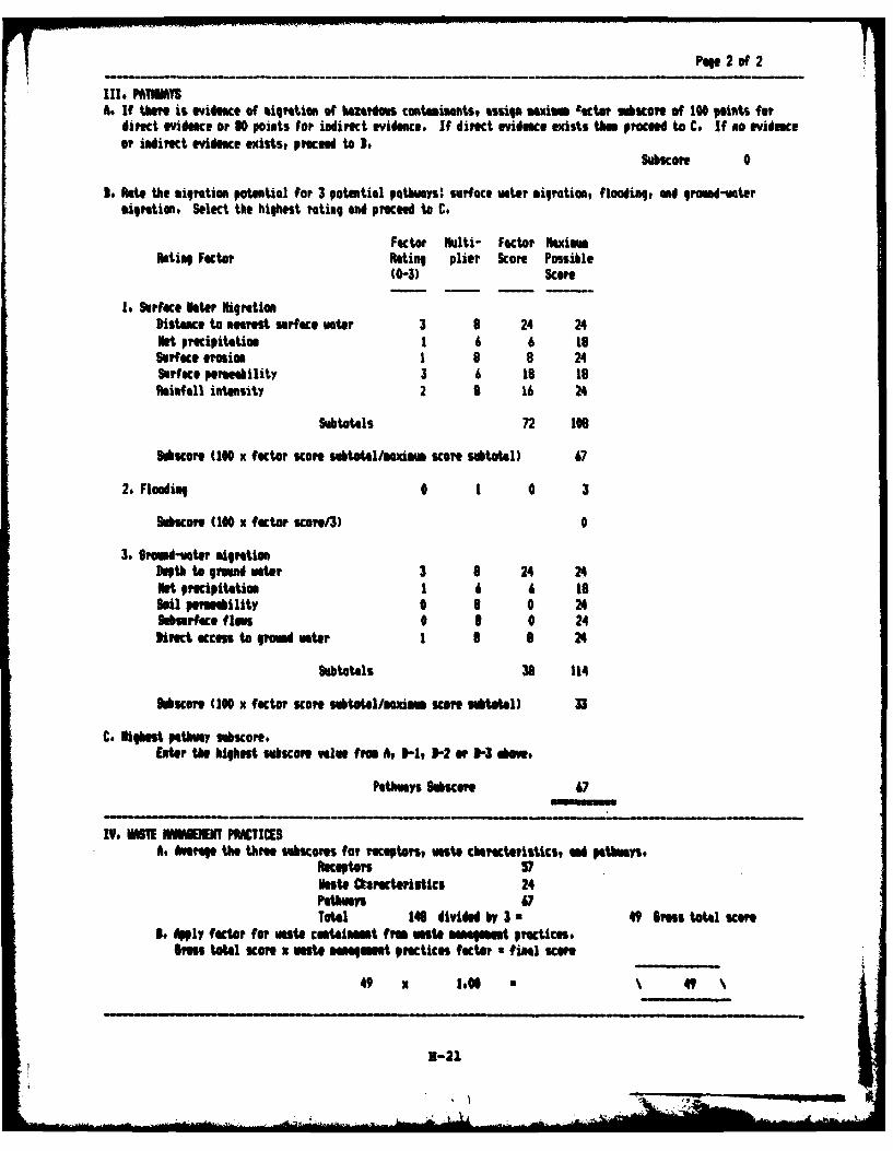
Page 2 of 2
As It there is eIec Of MIpTiUOR Of hazadous contaMitNts, ssg M io w M4 ac&tor gecoe Of 10 Points fordirect evidence or 30 poists for indirect evidence If direct evidence exists than proceed to Co If no evidenceOr indiret eVidence @Xists, proceed to Do
Subscore 0
So Rate the ipratiom potential for 3 potential pathways: surface water migration, flooding, end ground-watermigration. Select the highest foting and prOCeed t C.
Factor Nulti- Factor aximmRating Factor Rating plier Scope Possible
(0-3) Scope
1. Surface hater NilgretionDistance to neret sUrface water 3 8 24 24Net precipitation 1 6 6 toSurface erosion 1 8 8 24Serface permeability 3 6 18 19Railfall intensity 2 a 16 24
Subtotals 72 109
S&SCOre (10 X factor scare subtotal/MaxMm sore subtotal) 47
2. Flooding 0 1 0 3
SucoKOe (10 X factor score/3) 0
3. Bromnd-water MigrationDepth toground water 1 8 24 24Net precipitation 1 6 6 18Soil permebility 0 8 0 24Sabsrface flow 0 6 0 24Direct KCcesto grUd water I 1 8 24
Subtotals 36 114
hbscor (100 X factor Kcoe Subtotl/Memnm score 11btota) a3
C. ighest pathway subecore,Liter the highest suhsoPR VGIn ftu. A, I-1, ]-2 or N- aOwe
PathWays Sbore 6
IV, 61E IWMENEN PRACTIESAs Avorag the three siabscores for receptors, waste characteristics, ad pathwmays.
Receptors 57vast@ Cirocteristcs 24Peays 67Total 168 divided by 3 a 49 Brs total scOre
i. Apply factor for waste containment franato maNamnt pratices.raS total scOre X waste n gmt prectices factor *final sCOre
49 x 1.06O$4
B-21
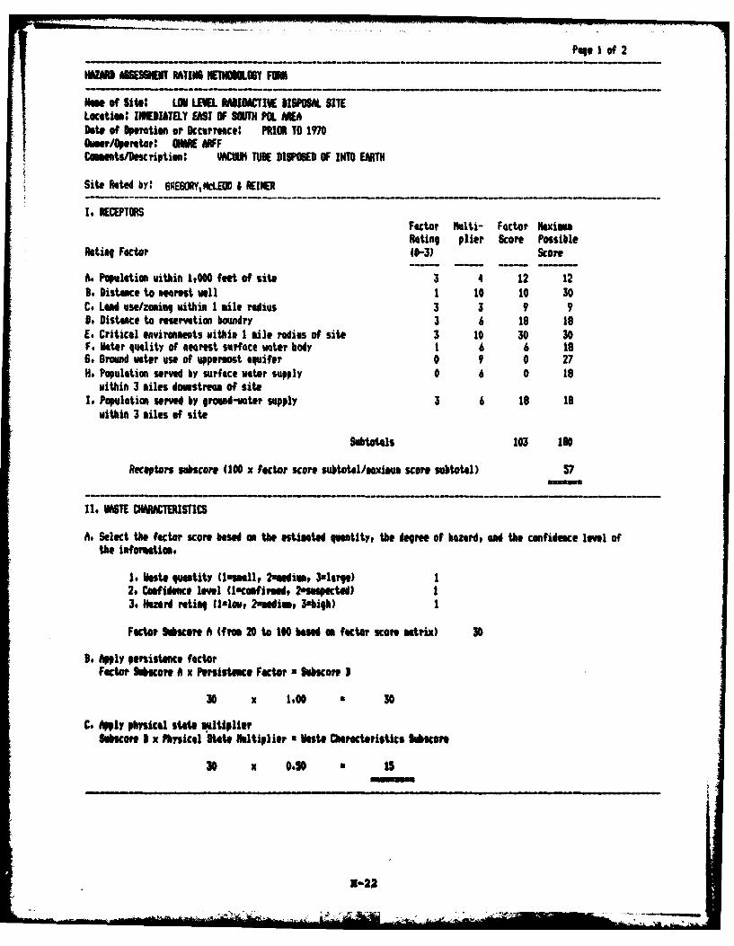
Pqe I of 2
OWzN ScEmW RW IEJI LHO.6Y FORN
Nme of Site: LOU LEWL RIDIACTIW ISPOSA SITELacation: IIEJATELY EAST OF SOUTH PL AADate of Operation or Occurrence' PRIOR TO 1970Ower/Operator' MFFCoamts/cription: VACUJM TE DISPOSED OF INTO EMTH
Site Rated by: 6E6ORYSLOD I REIER
I , RECPTORSFactor Multi- Factor MaximRating plier Score Possible
ting Factor 10-3) Score
A. Populatimn within 1,000 feet of site 3 4 12 12I. Distance to neaest well 1 10 10 30C. Lead use/zouinq within 1 mile radius 3 3 9 9n. Distance to reservation boundry 3 6 18 18E. Critical enviroments within I ile radius of site 3 10 30 30F. Voter qulity of nearest surface water body 1 6 6 19go ground water use of uppermost aquifer 0 9 0 27N. Population served by surface vter supply 0 6 0 18
within 3 tiles domstream of siteI. Population served by groand-vater supply 3 6 1 18
within 3 iles of site
Subtotals 103 188
Receptors uubscore (100 x factor score subtotel/axim score subtotal) 57
II. MSE CHAACTSTICS
A. Select the factor score based m the estimated quMtity, the degree of azerd, and the confidence level ofthe infortation.
1. Vste quantity (lasmll, 2zmediv, 3,1ev,) 12. Confidence Iml (lconfimed, 2-smpected) 13. Hazard rating flalou 2aendiv, 34big) 1
Factor Skscore A (from 20 to 100 baed am factr scoe mtix) 30
D. Apply persistence factorFactor Sobscore A x Persistance Factor Subscore I
30 x 1.00 • 30
C. Apply physical stte multiplierSlbscore I x Physical State Mltiplier a Wste Characteristics Subtcore
30 x 0.50 i 1s
2-22
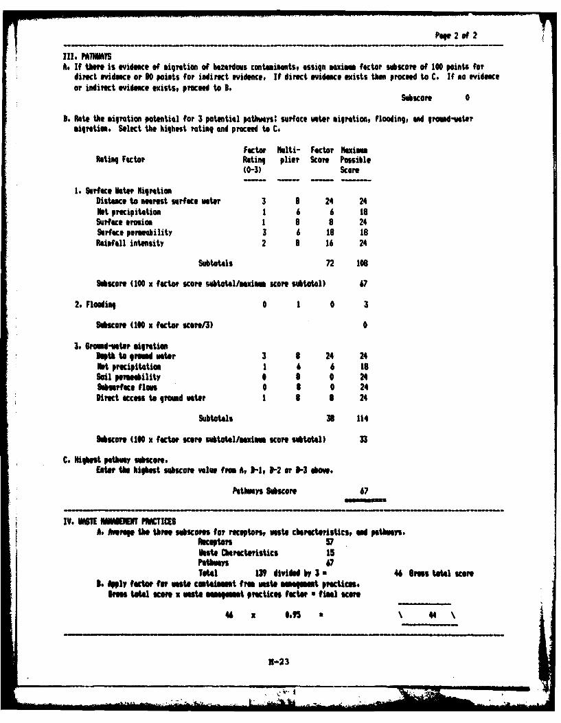
Page.~ 2-f
IIll PATHIMYSA. If there is evidmmce, of migration of hazardous contaminants, assign maxim factor subucOre Of 100 Points for
* direct evidence or SO points for indirect evidence. If direct evidence exists then proceed to C. If no evidenceor indirect evidence exists, proceed to 3L
Subscoe 0
3. Rote the migration potential for 3 potential pathways: surface water migration, flooding, ad ground-votermigration, Select the highest rating and proceed to C,
Factor Ihlti- Factor NaximamRlating Factor Raing plier Score Possible
(0-3) Score
t. Surface Mater NigratimiDistance to nearet Surface water 3 8 24 24Not precipitation 1 6 6 t8Surface erosion 1 9 9 24Surface permeability 3 6 is isRaInfIl intensity 2 3 16 24
Subtotals 72 108
Msone (100 x factor score subtotal/maximam score subtotal) 67
*2. Flooding 0 1 0 3
Siscmre (100 N factor scon/3) 0
3, Broaed-voter migrationDupthto ground water 3 9 24 24Not precipitation 1 6 6 18Soil PerueailIty 0 9 0 24hbUrface flows 0 9 0 24Direct access to ground water 1 9 9 24
Subtotals 39 114
Mscore (100 X factor scane subtotlmxim sca sUbtotal) 33
C. Highest pathwa suore.Edte the highest subscore value from A, 31, 1-2 or 31-3 above.
PathWaYS SubsOre 67
lye IMSTE HMMM PWCI(SAt Aerae the three seocome for receptoprs ate characteristicst ad pathways.
Raecaps 57Nest@ CheratertleSt 15Pathway6Total 139 divided by 3. 46 raSs total scOre
3. Aply factor for waste costonmemt fra ate management practices.Bras tota KOM X wate mngmen Practices factor final scOre
46 X so"5 44
1-23
~~OL
APPJIThIX I
RMFERENcMS
APPENDIX IREFERENCES
National Oceanic and Atmospheric Administration, 1977, ClimateAtlas of the United States: National Climatic Center, Ashville, NC.
National Oceanic and Atmospheric Administration, 1981, LocalClimatological Data for Chicago, Illinois, O'Hare International Airport.
Bradbury, J. C. and Atherton, E., 1965, The Precambrian Basement ofIllinois: Illinois Geological Survey Circ. 382.
Hughes, G. K., Kraatz, P.and Landon, R. A., 1966, Bedrock Aquifersof Northeastern Illinois: Illinois State Geological Survey Circ. 406, 15p.
Illinois Environmental Protection Agency, 1982, Title 35:Environmental Protection, Subtitle C: Water Pollution, Chapter 1:Pollution Control Board.
Landrum and Brown, Inc., 1983, Draft Environmental Impact Statementfor the Chicago O'Hare International Airport, 1984-1985 Master PlanDevelopment: Prepared for City of Chicago, Department of Aviation andDepartment of Transportation, Federal Aviation Administration.
National Oceanic and Admospheric Administration, 1968, RainfallFrequency Atlas of the United States: Weather Bureau Technical PaperNo. 40.
Suter, ., and others, 1959, Preliminary Report on Ground-WaterResources of the Chicago Region, Illinois: Illinois Geological Surveyand Illinois Water Survey Coop. Ground-Water Report. 1, 89 p.
U. S. Environmental Protection Agency, 1975, Federal Register, V.40, no. 248, pp. 59566-59588, December 24, 1975.
Walton, W. C., 1965, Ground-water Recharge in Illinois: IllinoisState Water Survey Report of Investigation 48, 55 p.
Willman, H. B., 1971, Bumary of the Geology of the Chicago Area:Illinois State Geological Survey Circ. 460, 77 p.
_____ ______ I
GLOSSARY 0F TERMINOLOGY AND ABBREVIATIONS
- 7II . -7
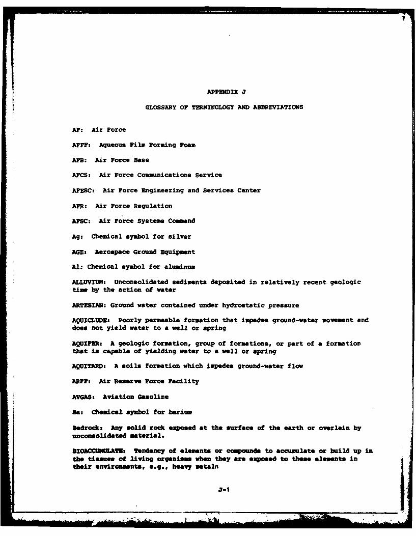
APPENDIX J
GLOSSARY OF TERMINOLOGY AND ABBREVIATIONS
AF: Air Force
AFFF: Aqueous Film Forming Foam
AFB: Air Force Base
AFCS: Air Force Communications Service
AFESC: Air Force Engineering and Services Center
AFR: Air Force Regulation
AFSC: Air Force Systems Command
Ag: Chemical symbol for silver
AGE: Aerospace Ground Equipment
Al: Chemical symbol for aluminum
ALLUVIUM: Unconsolidated sediments deposited in relatively recent geologictime by the action of water
ARTESIAN: Ground water contained under hydrostatic pressure
AQuICLUDE: Poorly permeable formation that impedes ground-water movement anddoes not yield water to a well or spring
AQUIFER: A geologic formation, group of formations, or part of a formation
that is capable of yielding water to a well or spring
AQUITARD: A soils formation which impedes ground-water flow
ARMF: Air Reserve Force Facility
AVGAS: Aviation Gasoline
Ba: Chemical symbol for barium
bedrock: Any solid rock exposed at the surface of the earth or overlain byunconsolidated material.
ROC UAs Tendency of elements or coiounds to accumulate or build up inthe tissues of living organism when they are exposed to these elements intheir environments, e.g., heavy metalm
J-1
CAP: Civilian Air Patrol
Cd: Chemical symbol for cadmium
CE: Civil Engineering
CERCLA: Comprehensive Environmental Response, Compensation and Liability Act
CES: Civil Engineering Squadron
CLOSURE: The completion of a set of rigidly defined functions for a hazardouswaste facility no longer in operation
COD: Chemical Oxygen Demand, a measure of the amount of oxygen required tooxidize organic and oxidizable inorganic compounds in water
COE: Corps of Engineers
COMD: Command
CONFINED AQUIFER: An aquifer bounded above and below by impermeable beds orby beds of distinctly lower permeability than that of the aquifer itself
CONTAMINATION: The degradation of natural water quality to the extent thatits usefulness is impaired; there is no implication of any specific limitssince the degree of permissible contamination depends upon the intended enduse or uses of the water
Cr: Chemical symbol for chromium
Cu: Chemical symbol for copper
DUVT: Detachment
DIP: The angle at which a stratum is inclined from the horizontal
DISPOSAL FACILITY: A facility or part of a facility at which hazardous wasteis intentionally placed into or on land or water, and at which waste will re-main after closure
DISPOSAL OF HAZARDOUS WASTE: The discharge, deposit, injection, dumping,spilling, or placing of any hazardous waste into or on land or water so thatsuch waste or any constituent thereof may enter the environment or be emittedinto the air or discharged into any waters, including ground water
DOD: Department of Defense
DOWNGRADINTs: In the direction of decreasing hydraulic static head; the direc-tion in which ground water flows
DPDO: Defense Property Disposal Office, previously included Redistributionand Marketing (R&M) and Salvage.
J-2
Amiss.'
DUMP: An uncovered land disposal site where solid and/or liquid wastes aredeposited with little or no regard for pollution control or aesthetics; dumpsare susceptible to open burning and are exposed to the elements, disease vec-tors and scavengers
EOD: Explosive Ordnance Disposal
EFFLUENT: A liquid waste discharge from a manufacturing or treatment process,in its natural state, or partially or completely treated, that discharges intothe environment
EP: Extraction Procedure, the EPA's standard laboratory procedure forleachate generation
EPA: U.S. Environmental Protection Agency
EROSION: The wearing away of land surface by wind or water
FAA: Federal Aviation Administration
FACILITY: Any land and appurtenances used for the treatment, storage and/ordisposal of hazardous wastes
Fe: Chemical symbol for iron
FLOOD PLAIN: The lowland and relatively flat areas adjoining inland and coast-al areas of the mainland and off-shore islands, including, at a minimum, areassubject to a one percent or greater chance of flooding in any given year
FLOW PATH: The direction or movement of ground water and any contaminantsthat may be contained therein, as governed principally by the hydraulicgradient
GC/4S: Gas chromatograph/mass spectrophotometer, a laboratory procedure foridentifying unknown compounds
GROUND WATER: Water beneath the land surface that is under atmospheric orartesian pressure
GROUND WATER RESERVOIR: The earth materials and the intervening open spacesthat contain ground water
HALF-LIFE: The time required for half the atoms present in radioactive sub-stance to decay
HARDFILL: Disposal sites receiving construction debris, wood, miscellaneous
spoil material
HARM: Hazard Assessment Rating Methodology
HAZARDOUS WASTE: A solid waste, or combination of solid wastes, which becauseof its quantity, concentration, or physical, chemical or infectious character-istics may cause or significantly contribute to an increase in mortality or anincrease in serious, irreversible, or incapacitating reversible illness; or
J-3
. . ..,,
pose a substantial present or potential hazard to human health or the environ-ment when improperly treated, stored, transported, or disposed of, or other-wise managed (RCRA)
HAZARDOUS WASTE GENERATION: The act or process of producing a hazardous waste
HEAVY METALS: Metallic elements, including the transition series, which in-clude many elements required for plant and animal nutrition in trace concen-trations but which become toxic at higher concentrations
Hg: Chemical symbol for mercury
HQ: Headquarters
HWMF: Hazardous Waste Management Facility
INCOMPATIBLE WASTE: A waste unsuitable for commingling with another waste ormaterial because the commingling might result in generation of extreme heat orpressure, explosion or violent reaction, fire, formation of substances whichare shock sensitive, friction sensitive, or otherwise have the potential forreacting violently, formation of toxic dusts, mists, fumes, and gases, volatil-ization of ignitable or toxic chemicals due to heat generation in such a man-ner that the likelihood of contamination of ground water or escape of the sub-stance into the environment is increased, any other reaction which might re-sult in not meeting the air, human health, and environmental standard
INFILTRATION: The gradual passing of liquid through matter.
IRP: Installation Restoration Program
JP-4: Jet Fuel
LEACHATE: A solution resulting from the separation or dissolving of solubleor particulate constituents from solid waste or other man-placed medium bypercolation of water
LEACHING: The process by which soluble materials in the soil, such as nu-trients, pesticide chemicals or contaminants, are washed into a lover layer ofsoil or are dissolved and carried away by water
LINER: A continuous layer of natural or man-made materials beneath or on thesides of a surface impoundment, landfill, or landfill cell which restricts thedownward or lateral escape of hazardous waste, hazardous waste constituents orleachate
LOESS: A sediment composed dominantly of silt-size particles that has beendeposited primarily by the wind
LOX: Liquid Oxygen
LYSIHZt8: A vacuum operated sampling device used for extracting pore water
samples at various depths within the unsaturated zone
MU: Methyl Ethyl Ketone0-4
J-..
MGD: million gallons per day
MOA: Military Operating Area
MOGAS: Motor gasoline
Mn: Chemical symbol for manganese
MONITORING WELL: A well used to measure ground-water levels and to obtainsamples
MSL: Mean Sea Level
MUNITION ITEM:S Munitions or portions of munitions having an explosivepotential
MUNITIONS RESIDUE: Non-explosive segments of waste munitions (i.e., bombcasings)
NCO: Non-commissioned Officer
NCOIC: Non-commissioned officer In-Charge
NDI Non-destructive Inspection
NET PRECIPITATION: The amount of annual precipitation minus annual evaporation
NGVD: National Geodetic Vertical Datum
Ni: Chemical symbol for nickel
NPDES: National Pollutant Discharge Elimination System
03L: Occupational and Environmental Health Laboratory
ORGANIC: Being, containing or relating to carbon compounds, especially inwhich hydrogen is attached to carbon
O&G: Symbols for oil and grease
OSI: Office of Special Investigations
OVA: Organic Vapor Analyzer
Pb: Chemical symbol for lead
PCs$ Polychlorinated iphenylsi highly toxic to aquatic life; they persist in
the environment for long period and are biologically accumulative
PERCOLATION: Movement of moisture by gravity or hydrostatic pressure throughinterstices of unsaturated rock or soil
PERMRILITYs The rate at which fluids may move through a solid, porous medium
J-5
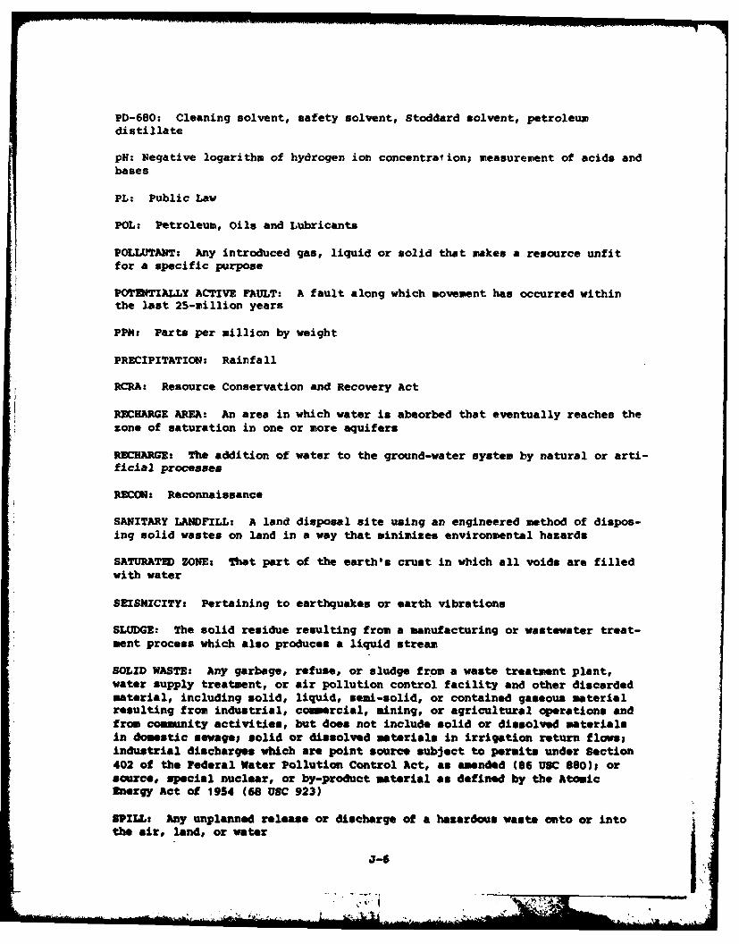
PD-680: Cleaning solvent, safety solvent, Stoddard solvent, petroleumdistillate
pH: Negative logarithm of hydrogen ion concentration; measurement of acids andbases
PL: Public Law
POL: Petroleum, Oils and Lubricants
POLLUTANT: Any introduced gas, liquid or solid that makes a resource unfitfor a specific purpose
POTEITIALLY ACTIVE FAULT: A fault along which movement has occurred within
the last 25-million years
PPM: Parts per million by weight
PRECIPITATION: Rainfall
RCRA: Resource Conservation and Recovery Act
RECHARGE AREA: An area in which water is absorbed that eventually reaches thezone of saturation in one or more aquifers
RECHARGE: The addition of water to the ground-water system by natural or arti-ficial processes
RECON: Reconnaissance
SANITARY LANDFILL: A land disposal site using an engineered method of dispos-ing solid wastes on land in a way that minimizes environmental hazards
SATURATE) ZONE: That part of the earth's crust in which all voids are filledwith water
SEISMICITY: Pertaining to earthquakes or earth vibrations
SLUDGE: The solid residue resulting from a manufacturing or wastewater treat-ment process which also produces a liquid stream
SOLID WASTE: Any garbage, refuse, or sludge from a waste treatment plant,water supply treatment, or air pollution control facility and other discardedmaterial, including solid, liquid, semi-solid, or contained gaseous materialresulting from industrial, commercial, mining, or agricultural operations andfrom community activities, but does not include solid or dissolved materialsin domestic sawage; solid or dissolved materials in irrigation return flows;industrial discharges which are point source subject to permits under Section402 of the Federal Water Pollution Control Act, as amended (86 USC 880)1 orsource, special nuclear, or by-product material as defined by the AtomicEnergy Act of 1954 (68 USC 923)
SPILL: Any unplanned release or discharge of a hazardous waste onto or intothe air, land, or water
J7-6
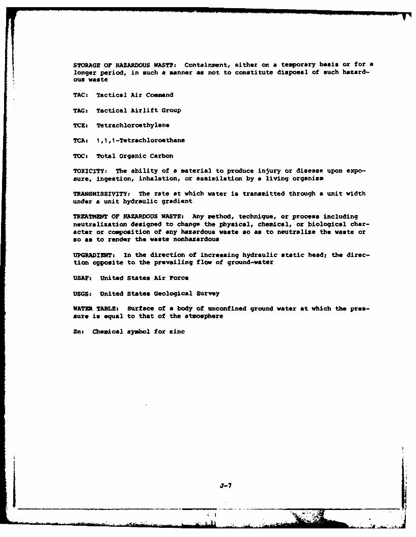
STORAGE OF HAZARDOUS WAST: Containment, either on a temporary basis or for a
longer period, in such a banner as not to constitute disposal of such hazard-ous waste
TAC: Tactical Air Comand
TAG: Tactical Airlift Group
TCE: Tetrachloroethylene
TCA: 1,1,1-Tetrachloroethane
ToC: Total Organic Carbon
TOXICITY: The ability of a material to produce injury or disease upon expo-sure, ingestion, inhalation, or assimilation by a living organism
TRANSMISSIVITY: The rate at which water is transmitted through a unit widthunder a unit hydraulic gradient
TREATMENT OF HAZARDOUS WASTE: Any method, technique, or process includingneutralization designed to change the physical, chemical, or biological char-acter or composition of any hazardous waste so as to neutralize the waste orso as to render the waste nonhazardous
UPGRADIENT: In the direction of increasing hydraulic static head; the direc-
tion opposite to the prevailing flow of ground-water
USAF: United States Air Force
USGS: United States Geological Survey
WATER TABLE: Surface of a body of unconfined ground water at which the pres-sure is equal to that of the atmosphere
Zn: Chemical symbol for zinc
J-7
APPW3IX K
IUD3X
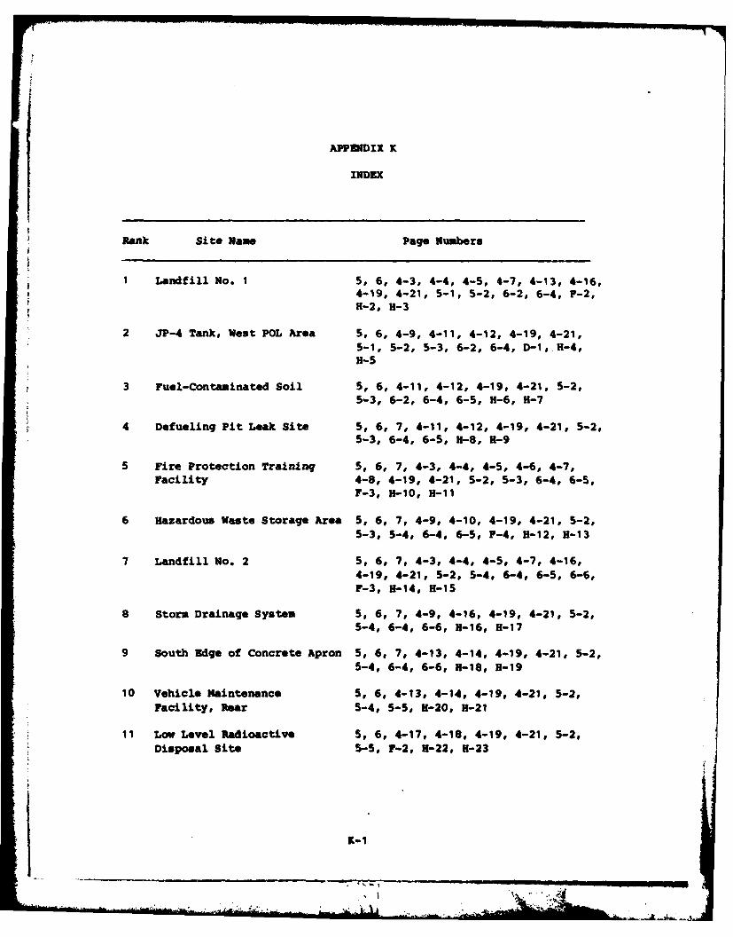
APPENDIX K
INDEX
Rank Site Name Page Numbers
1 Landfill No. 1 5, 6, 4-3, 4-4, 4-5, 4-7, 4-13, 4-16,4-19, 4-21, 5-1, 5-2, 6-2, 6-4, F-2,H-2, H-3
2 JP-4 Tank, West POL Area 5, 6, 4-9, 4-11, 4-12, 4-19, 4-21,
5-1, 5-2, 5-3, 6-2, 6-4, D-1, H-4,H-5
3 Fuel-Contaminated Soil 5, 6, 4-11, 4-12, 4-19, 4-21, 5-2,5-3, 6-2, 6-4, 6-5, H-6, H-7
4 Defueling Pit Leak Site 5, 6, 7, 4-11, 4-12, 4-19, 4-21, 5-2,5-3, 6-4, 6-5, H-8, H-9
5 Fire Protection Training 5, 6, 7, 4-3, 4-4, 4-5, 4-6, 4-7,Facility 4-8, 4-19, 4-21, 5-2, 5-3, 6-4, 6-5,
F-3, B-10, H-11
6 Hazardous Waste Storage Area 5, 6, 7, 4-9, 4-10, 4-19, 4-21, 5-2,5-3, 5-4, 6-4, 6-5, F-4, B-12, B-13
7 Landfill No. 2 5, 6, 7, 4-3, 4-4, 4-5, 4-7, 4-16,4-19, 4-21, 5-2, 5-4, 6-4, 6-5, 6-6,F-3, H-14, H-15
8 Storm Drainage System 5, 6, 7, 4-9, 4-16, 4-19, 4-21, 5-2,5-4, 6-4, 6-6, H-16, H-17
9 South Edge of Concrete Apron 5, 6, 7, 4-13, 4-14, 4-19, 4-21, 5-2,5-4, 6-4, 6-6, H-18, H-19
10 Vehicle Maintenance 5, 6, 4-13, 4-14, 4-19, 4-21, 5-2,Facility, Rear 5-4, 5-5, U-20, H-21
11 Low Level Radioactive 5, 6, 4-17, 4-18, 4-19, 4-21, 5-2,Disposal Site 5-5, r-2, U-22, H-23
K-1
Related Documents


