Athens Institute for Education and Research ATINER ATINER's Conference Paper Series CIV2015-1752 Enkeleda Kokona PhD Student Polytechnic University of Tirana Albania Helidon Kokona PhD Student Institute of Earthquake Engineering and Engineering Seismology IZIIS FYROM Altin Bidaj Lecturer Polytechnic University of Tirana Albania Assessment of Mesh Size Refinement Influence on FEM Solution of Shear Wall Structural Systems

Welcome message from author
This document is posted to help you gain knowledge. Please leave a comment to let me know what you think about it! Share it to your friends and learn new things together.
Transcript

ATINER CONFERENCE PAPER SERIES No: LNG2014-1176
1
Athens Institute for Education and Research
ATINER
ATINER's Conference Paper Series
CIV2015-1752
Enkeleda Kokona
PhD Student
Polytechnic University of Tirana
Albania
Helidon Kokona
PhD Student
Institute of Earthquake Engineering and Engineering Seismology
IZIIS
FYROM
Altin Bidaj
Lecturer
Polytechnic University of Tirana
Albania
Assessment of Mesh Size Refinement
Influence on FEM Solution of Shear Wall
Structural Systems
ATINER CONFERENCE PAPER SERIES No: CIV2015-1752
2
An Introduction to
ATINER's Conference Paper Series
ATINER started to publish this conference papers series in 2012. It includes only the
papers submitted for publication after they were presented at one of the conferences
organized by our Institute every year. This paper has been peer reviewed by at least two
academic members of ATINER.
Dr. Gregory T. Papanikos
President
Athens Institute for Education and Research
This paper should be cited as follows:
Kokona, E., Kokona, H. and Bidaj, A. (2015). "Assessment of Mesh Size
Refinement Influence on FEM Solution of Shear Wall Structural Systems",
Athens: ATINER'S Conference Paper Series, No: CIV2015-1752.
Athens Institute for Education and Research
8 Valaoritou Street, Kolonaki, 10671 Athens, Greece
Tel: + 30 210 3634210 Fax: + 30 210 3634209 Email: [email protected] URL:
www.atiner.gr
URL Conference Papers Series: www.atiner.gr/papers.htm
Printed in Athens, Greece by the Athens Institute for Education and Research. All rights
reserved. Reproduction is allowed for non-commercial purposes if the source is fully
acknowledged.
ISSN: 2241-2891
14/12/2015
ATINER CONFERENCE PAPER SERIES No: CIV2015-1752
3
Assessment of Mesh Size Refinement Influence on FEM
Solution of Shear Wall Structural Systems
Enkeleda Kokona
Helidon Kokona
Altin Bidaj
Abstract
This paper presents FEM modelling through a structural analyses code of a
Reinforced Concrete Structure "4ever green" tower. The structure is located in
the center of Tirana, the capital of Albania. The tower has 6 levels
underground, (pit depth 26 m) and 24 levels above ground (height 95 m). The
structural system applied is reinforced concrete, composed of coupled walls
located in perimeter line and staircase shafts. So, the vertical and lateral forces
are fully resisted by shear walls. From a structural point of view it's necessary
to develop a structural model in different types of mesh refinement to achieve
better results, avoiding the solution errors on the stress-strain and deformation
state over the structural elements. FEM detailed description is not the goal of
this paper. The principal goal of this paper is to present case studies with
respective results that help to achieve realistic structural behaviour directly
connected to themesh refinement applied. Quadrilateral displacement elements
meshing as practical and accurate procedures are used. After the computational
solution, forces and displacements analyses results are presented for three
levels of mesh densities. As it is known the basic idea that the FEM solution of
a real problem is replacing it by a simpler one, we are able to find only an
approximate and not exact solution. Thus in the absence of the exact solution
that defines theoretically an asymptote line we can only improve or refine the
FEM solution by spending a more computational effort. Small differences in
analyses results in between solutions for two last consecutive mesh densities,
yields practically asymptote line, accepted as a satisfactory solution.
Keywords: Asymptote, mesh, refinement, reinforced concrete, shear wall
Acknowledgments: Our thanks to colleagues of “aei progetti” structural
design studio, Ing. Niccolò De Robertis, Ing. Stefano Valentini for their helpful
collaboration and support to achive the optimal solution of “4 Ever Green"
Tower, Tirana.
ATINER CONFERENCE PAPER SERIES No: CIV2015-1752
4
Introduction
The behaviour of a real structure depends upon the geometry, the property
of the material used, the boundary and the initial and loading conditions. In
general, it is very difficult to solve the differential equations of the structural
model [1].
In practice, the problems are solved using numerical methods. The
methods of model discretization like the FEM are popular, due to its
practicality. The main principle of FEM is the modeling of real physical
structure as an assemblage of individual elements. In structural modeling there
are three basic element types: displacement elements, equilibrium elements and
hybrid elements [2]. The software package SAP2000 used for the structure
presented in this paper employs displacement elements.
The computational modeling using the FEM consists of four steps:
• Modeling of the geometry.
• Meshing (discretization).
• Specification of material property.
• Specification of boundary, initial and loading conditions.
Modeling of the Geometry
Real complex structures have to be reduced by simpler geometry. The
geometry is eventually presented by a collection of elements at different
shapes, approximated by straight lines or flat surfaces.
The accuracy of representation is controlled by the number of elements
interconnected. It is obvious that with more elements, the representation would
be more accurate. Because of the constraints on computational efforts, it is
always recommended to limit the number of elements.
Compromises are usually made in order to decide a suitable number of
elements. Hence, fine geometry needs to be modeled only if very accurate
results are required in specific regions. The engineers have to interpret the
results having in mind these geometric approximations.
There are many ways to create a suitable geometry in the computer for the
FE mesh. Points called nodes are specified by their coordinates. Lines are
specified connecting the points or nodes. Surfaces are specified by connecting,
rotating or translating lines; and solids can be specified by connecting, rotating
or translating surfaces.
Graphic interfaces are used to provide the structural geometry. There are
software packages which can significantly save time creating the model of
structural geometry.
Engineering experience and judgment are very important in modeling the
geometry of a system, using necessary simplifications required. For example, a
physical plate geometrically has three dimensions but a mathematical model is
presented in two dimensions.
It is similar in shells presented by a two-dimensional flat surface. Shell
elements are used in meshing surfaces.

ATINER CONFERENCE PAPER SERIES No: CIV2015-1752
5
A physical beam geometrically has also three dimensions. The beam is
presented mathematically in one dimension, so the mathematical model is a
one-dimensional line. Beam elements are used to mesh the lines of models.
Meshing
Meshing is used to discretize the geometry into small pieces called
elements. The solution for a structural problem is complex, using a variety of
functions over the whole geometry of the problem.
The geometry can be divided (meshed) into subdivisions or elements using
grids or nodes.
The solution within an element can be assumed using suitable functions
such as polynomials. The solutions assumed for all elements, simple from a
computational point of view satisfying convergence requirements, form the
solution over the whole geometry of the structure.
The element connectivity information given along with meshing will be
used later in the FEM equations.
Generally the solution is taken in polynomial form.
Triangulation is the most flexible way to create meshes. It can be made for
two-dimensional (2D) planes, and even three-dimensional (3D) spaces. It is
commonly used as a meshing type in most of the pre-processors. The
advantage of triangulation is the flexible modeling of complex geometry and
boundaries as well.
Quadrilateral element meshing is more difficult and more accurate way to
create meshes.
Specification of Material Properties
The property of materials used in the structure can be defined for a group
of elements or individually. Different sets of material properties like Young’s
modulus, shear modulus etc, are required for the FEM analysis of structures.
Boundaries, Initial and Loading Conditions
Boundaries, initial and loading conditions are decisive in FEM solutions.
Those conditions are easily defined using commercial pre-processors, through
a graphic interface. It can be specified to the geometrical identities (points,
lines, surfaces, solids), or to the elements as well.
Engineering experience and judgment is required to correctly define the
boundaries, initial and loading conditions for structural systems.
Mesh Refinement Techniques
The mesh defines the shape of an element and the shape is significant for
an element to produce accurate stress levels within the structure.
Finite element analysis would proceed starting from the selection of a
mesh. Experience is practically the only way in determining whether or not the
mesh is optimal for the analysis [2].
ATINER CONFERENCE PAPER SERIES No: CIV2015-1752
6
The mesh needs to be graded in areas of importance, such as zones of
stress concentration, rapid change in stress in a specific direction, corners and
holes, change in material properties etc.
Element Distortion
Usually it is not possible to have always regular shaped elements for
variational geometries. Irregular or distorted elements are acceptable in the
FEM, but there are limitations. So, it needs to control the degree of element
distortion in the process of mesh generation [4], [6].
The distortions are measured regarding to the basic shape of the element,
which are
• Quadrilateral elements
• Triangle elements
• Hexahedron elements
• Tetrahedron elements
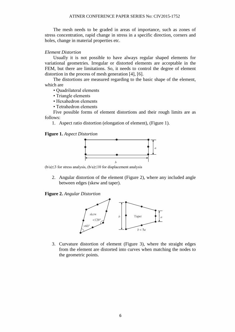
Five possible forms of element distortions and their rough limits are as
follows:
1. Aspect ratio distortion (elongation of element), (Figure 1).
Figure 1. Aspect Distortion
(b/a)≤3 for stress analysis, (b/a)≤10 for displacement analysis
2. Angular distortion of the element (Figure 2), where any included angle
between edges (skew and taper).
Figure 2. Angular Distortion
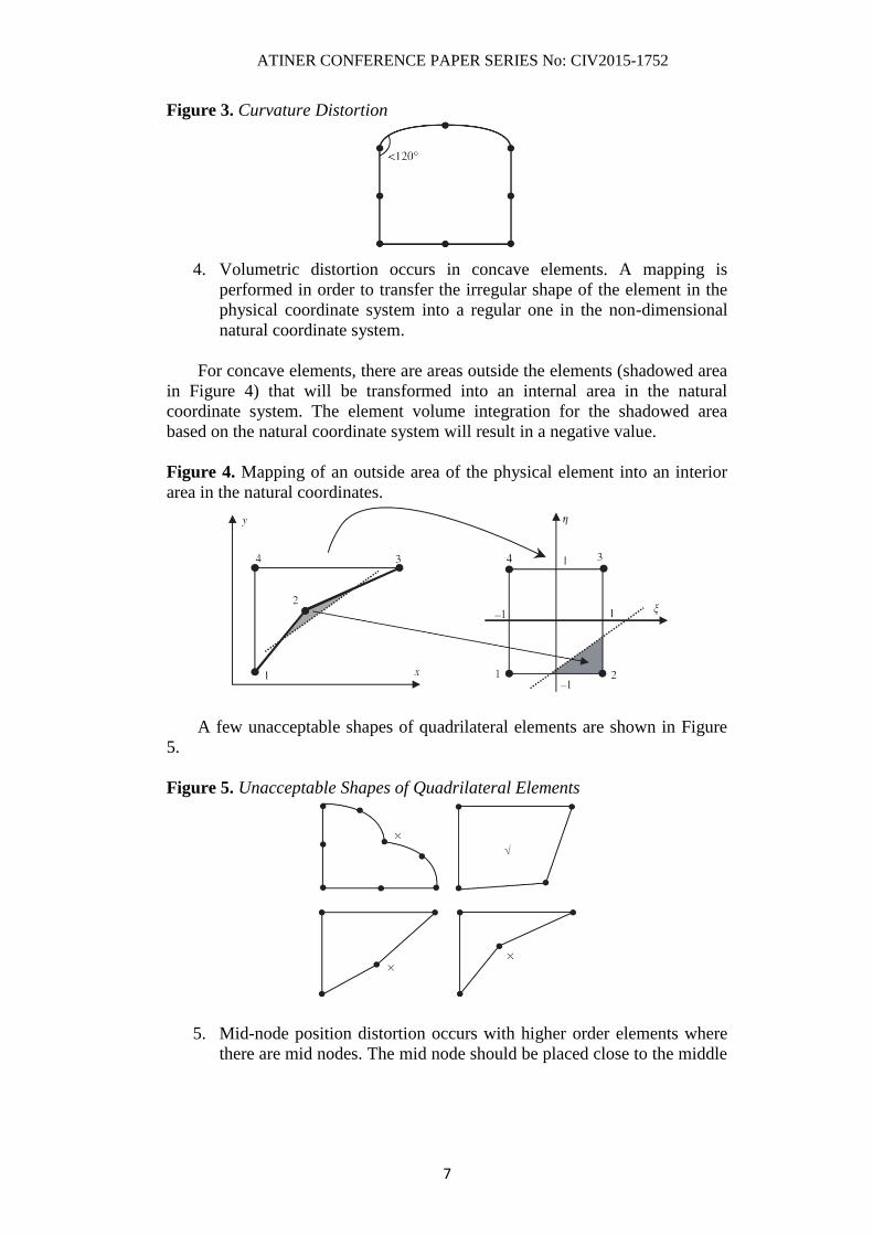
3. Curvature distortion of element (Figure 3), where the straight edges
from the element are distorted into curves when matching the nodes to
the geometric points.
ATINER CONFERENCE PAPER SERIES No: CIV2015-1752
7
Figure 3. Curvature Distortion
4. Volumetric distortion occurs in concave elements. A mapping is
performed in order to transfer the irregular shape of the element in the
physical coordinate system into a regular one in the non-dimensional
natural coordinate system.
For concave elements, there are areas outside the elements (shadowed area
in Figure 4) that will be transformed into an internal area in the natural
coordinate system. The element volume integration for the shadowed area
based on the natural coordinate system will result in a negative value.
Figure 4. Mapping of an outside area of the physical element into an interior
area in the natural coordinates.
A few unacceptable shapes of quadrilateral elements are shown in Figure
5.
Figure 5. Unacceptable Shapes of Quadrilateral Elements
5. Mid-node position distortion occurs with higher order elements where
there are mid nodes. The mid node should be placed close to the middle
ATINER CONFERENCE PAPER SERIES No: CIV2015-1752
8
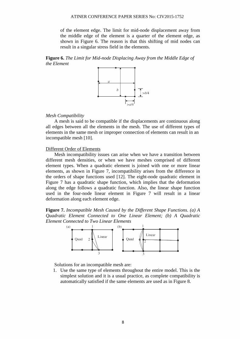
of the element edge. The limit for mid-node displacement away from
the middle edge of the element is a quarter of the element edge, as
shown in Figure 6. The reason is that this shifting of mid nodes can
result in a singular stress field in the elements.
Figure 6. The Limit for Mid-node Displacing Away from the Middle Edge of
the Element
Mesh Compatibility
A mesh is said to be compatible if the displacements are continuous along
all edges between all the elements in the mesh. The use of different types of
elements in the same mesh or improper connection of elements can result in an
incompatible mesh [10].
Different Order of Elements
Mesh incompatibility issues can arise when we have a transition between
different mesh densities, or when we have meshes comprised of different
element types. When a quadratic element is joined with one or more linear
elements, as shown in Figure 7, incompatibility arises from the difference in
the orders of shape functions used [12]. The eight-node quadratic element in
Figure 7 has a quadratic shape function, which implies that the deformation
along the edge follows a quadratic function. Also, the linear shape function
used in the four-node linear element in Figure 7 will result in a linear
deformation along each element edge.
Figure 7. Incompatible Mesh Caused by the Different Shape Functions. (a) A
Quadratic Element Connected to One Linear Element; (b) A Quadratic
Element Connected to Two Linear Elements
Solutions for an incompatible mesh are:
1. Use the same type of elements throughout the entire model. This is the
simplest solution and it is a usual practice, as complete compatibility is
automatically satisfied if the same elements are used as in Figure 8.

ATINER CONFERENCE PAPER SERIES No: CIV2015-1752
9
Figure 8. Elements of the Same Type with Complete Edge-to-Edge Connection
Ensures Mesh Compatibility
2. When elements of different orders of shape functions have to be used
for some reason, such as in p-adaptive analysis, use transition elements
whose shape functions have different orders on different edges. An
example of a transition element is shown in Figure 9. The five-node
element shown can behave in a quadratic fashion on the left edge and
linearly on the other edges. In this way, the compatibility of the mesh
can be guaranteed.
Figure 9. Five Nodes Transition Element Used to Connect Linear and
Quadratic Wlements to Ensure Mesh Compatibility
3. Another method used to enforce mesh compatibility is to use multipoint
constraints (MPC) equations. MPCs can be used to enforce
compatibility for the cases shown in Figure 7(a).
Straddling Elements
Straddling elements can also result in mesh incompatibility, as illustrated
in Figure 10. Although the shape functions order of these connected elements
is the same, the straddling can result in an incompatible deformation of edges
1-2, and 2-3, shown by dotted lines in Figure 10. This is because in the
assembly of elements, the FEM requires only the continuity of the
displacements (not the derivatives) at nodes between elements. The method for
fixing the problem of the mesh incompatibility is to avoid straddling elements
in the mesh [14].

ATINER CONFERENCE PAPER SERIES No: CIV2015-1752
10
Figure 10. Incompatible Mesh Caused by Straddling along the Common Edge
of the Same Order of Elements
Meshing Accuracy Ladder
The solution accuracy requires the generation mesh refining, coarsening,
relocating, or adjusting locally polynomial degree.
The computation starts with a coarse mesh solution with a low order of
polynomial degree [1],[8]. If accuracy isn’t achieved, the following adaptive
procedures can be used:
• Local refinement and/or coarsening of a mesh (h-refinement)
The easy manner to move up the accuracy ladder is to employ finite
element codes that automatically increase the number of elements used in an
analysis. Increasing the number of elements within a model without changing
the order of the polynomial used to approximate the displacements within the
element automatically is known as h-adaption. This adaption process is
illustrated in Figure 11, where a 2-D 4-noded membrane element is used.
Figure 11. h-refinement
The usual way of avoiding the excess h-refinement is to introduce irregular
nodes where the edges of a refined element meet at the midsides of a coarser
one, Figure 12.
The way to retain continuity at irregular nodes is to restrict displacement
for irregular node i, ui(xi,yi) constructing shape functions on each element [11].
The difficulties arise when there are too many irregular nodes on an edge. To
overcome this, typically we use “one irregular” and “three neighbor”rules. The
“one irregular” rule limits the number of irregular nodes on an element edge to
one. The “three neighbor” rule states that any element having irregular nodes
on three of its four edges must be refined [13].

ATINER CONFERENCE PAPER SERIES No: CIV2015-1752
11
Figure 12. Bisection of an Element Mesh (Left). Mesh Lines Removed by
Creating Irregular Nodes (Right)
Irregular nodes can be avoided by using transition elements as shown in
Figure 13. On the right are used triangular elements as a transition between the
coarse and fine elements. If triangular elements are not desirable the transition
element on the left uses rectangles but only adds a mid-edge shape functions at
Node 3.
Figure 13. Transition Elements between Coarse and Fine Elements Using
Rectangles (Left) and Triangles (Right)
• Locally varying the polynomial degree (p-refinement)
An alternative to employing more elements is to move up the accuracy
ladder by increasing the order of the polynomial used within the element to
model the displacement field. This process is known as p-refinement. The
number of nodes per element increases, with the same number of elements.
This is demonstrated using a simple 2-D model in Figure 14.
Figure 14. p-refinement
• relocating or moving a mesh (r-refinement)
The r-refinement is not capable of finding an accurate solution. If the mesh
is too coarse it might be impossible to achieve a high degree of precision.
The above procedures can be used separately or in combination [4]. So far,
h-refinement is the most popular. It can increase the convergence rate
particularly when singularities are present. The p-refinement is most natural

ATINER CONFERENCE PAPER SERIES No: CIV2015-1752
12
with a hierarchical basis, since parts of the stiffness, mass matrices and load
vector will remain unchanged while increasing the polynomial degree [5].
Mesh Refinement Influence in Practical Solution
"4 Ever Green" Tower General Description
The tower structure is 95 m high above the ground (24 floors) with a
development in depth down -26.0 m from ground level (6 levels).
The foundation slab of 2.40m thickness is nearly a rectangular shape with
longitudinal sides equal to 39m and transversal side variable from 27m to
28.6m. The underground levels of 2.8m inter-storey height are reinforced
concrete slabs of 30cm thickness, reduced to 24cm at ducts and pipelines holes
passing through slabs, vertical elements and RC walls and columns of 40cm
thick.
The underground levels from the sixth to the second floor are intended
mainly for parking, on the sixth floor there are also technical spaces intended
for sanitary and firefighting water tanks. The entrance to the parking area is
realized through the RC ramp that goes down from the ground floor to the
second basement level.
At the first underground level it is a rigid basement of 1.4m thickness for
the tower vertical structure.
The upper levels of the structure have inscribed a variation edges shape,
starting from 26mx22m at the tower base, to 30mx26m on the top.
In the center of the first four levels above the ground circular openings, to
allow the installation of escalators, are provided.
The fifth level is intended for conference room venue. The inter-storey
height of these levels is 5m.
Starting from the sixth level +25.07m, up to the top level +95.00m, the
inter-storey height 3.5m remains constant. The destinations for levels, from six
to ten are offices, from eleven to twenty are hotels, the twenty-first and twenty-
second, residential.
In the center of the floor slabs, free span dimensions are 13mx13m.
There are no vertical elements supporting the loads of stairs that are applied on
the perimeter walls of the tower through the slab, the thickness of which is
equal to 40cm. The slabs are made of reinforced concrete lightened, using
polyethylene hollow spheres in high density.
The perimeter walls of the tower have tapered thickness with the height
and vary from 40cm at the base to 25cm at the top. The walls of the elevator
cores and stair shafts have a constant thickness of 40cm throughout the height
of the tower.
"4 Ever Green" Tower Structural Modelling, Meshing and Analyses Results
A structural analysis is performed using finite element modeling, using the
computer program SAP 2000. Some of the major assumptions used in FEM
modeling are presented below:
ATINER CONFERENCE PAPER SERIES No: CIV2015-1752
13
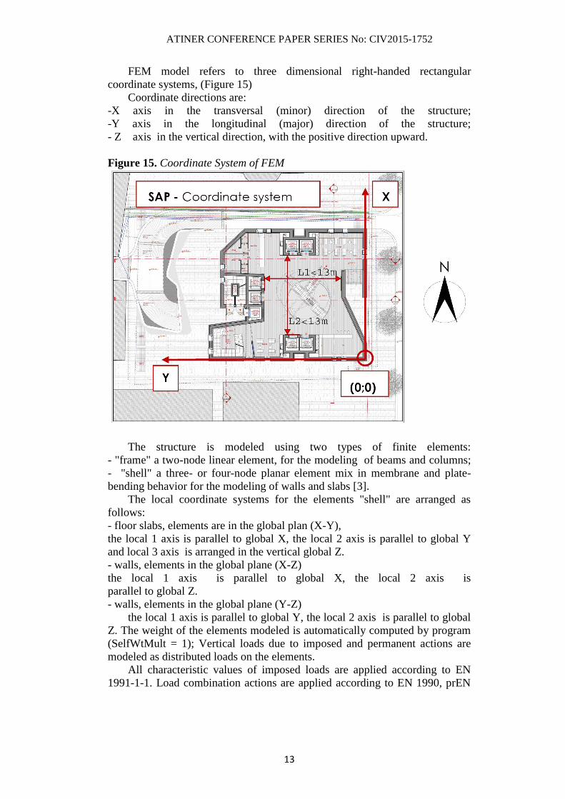
FEM model refers to three dimensional right-handed rectangular
coordinate systems, (Figure 15)
Coordinate directions are:
-X axis in the transversal (minor) direction of the structure;
-Y axis in the longitudinal (major) direction of the structure;
- Z axis in the vertical direction, with the positive direction upward.
Figure 15. Coordinate System of FEM
The structure is modeled using two types of finite elements:
- "frame" a two-node linear element, for the modeling of beams and columns;
- "shell" a three- or four-node planar element mix in membrane and plate-
bending behavior for the modeling of walls and slabs [3].
The local coordinate systems for the elements "shell" are arranged as
follows:
- floor slabs, elements are in the global plan (X-Y),
the local 1 axis is parallel to global X, the local 2 axis is parallel to global Y
and local 3 axis is arranged in the vertical global Z.
- walls, elements in the global plane (X-Z)
the local 1 axis is parallel to global X, the local 2 axis is
parallel to global Z.
- walls, elements in the global plane (Y-Z)
the local 1 axis is parallel to global Y, the local 2 axis is parallel to global
Z. The weight of the elements modeled is automatically computed by program
(SelfWtMult = 1); Vertical loads due to imposed and permanent actions are
modeled as distributed loads on the elements.
All characteristic values of imposed loads are applied according to EN
1991-1-1. Load combination actions are applied according to EN 1990, prEN
ATINER CONFERENCE PAPER SERIES No: CIV2015-1752
14
1998-1. Material properties and partial factors for materials are applied
according to prEN 1992-1-1.
The units used in the model are kN and meter.
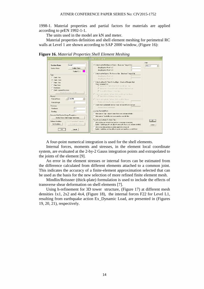
Material properties definition and shell element meshing for perimetral RC
walls at Level 1 are shown according to SAP 2000 window, (Figure 16):
Figure 16. Material Properties Shell Element Meshing
A four-point numerical integration is used for the shell elements.
Internal forces, moments and stresses, in the element local coordinate
system, are evaluated at the 2-by-2 Gauss integration points and extrapolated to
the joints of the element [9].
An error in the element stresses or internal forces can be estimated from
the difference calculated from different elements attached to a common joint.
This indicates the accuracy of a finite-element approximation selected that can
be used as the basis for the new selection of more refined finite element mesh.
Mindlin/Reissner (thick-plate) formulation is used to include the effects of
transverse shear deformation on shell elements [7].
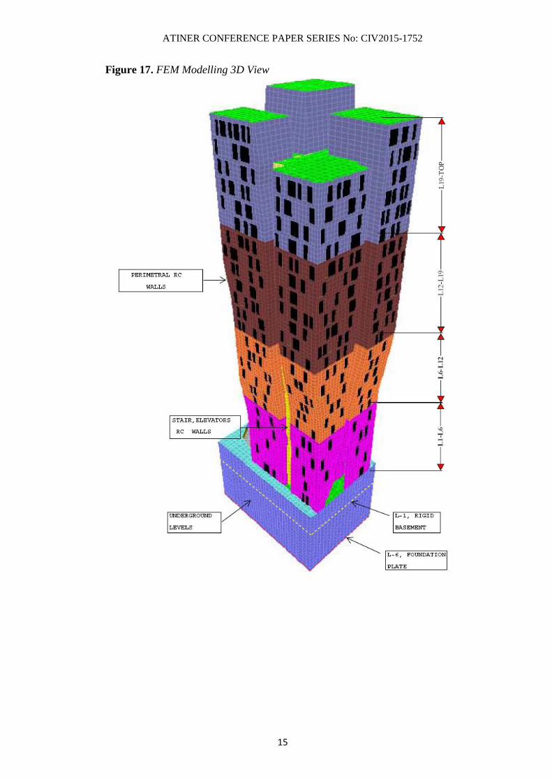
Using h-refinement for 3D tower structure, (Figure 17) at different mesh
densities 1x1, 2x2 and 4x4, (Figure 18), the internal forces F22 for Level L1,
resulting from earthquake action Ex_Dynamic Load, are presented in (Figures
19, 20, 21), respectively.
ATINER CONFERENCE PAPER SERIES No: CIV2015-1752
15
Figure 17. FEM Modelling 3D View

ATINER CONFERENCE PAPER SERIES No: CIV2015-1752
16
Figure 18. Mesh Densities
Coarse Mesh (1x1)
Medium Mesh (2x2)
Fine Mesh (4x4)

ATINER CONFERENCE PAPER SERIES No: CIV2015-1752
17
Figure 19. Element Forces F22, Ex_Dynamic Load, Mesh Density (1x1)
Figure 20. Element Forces F22, Ex_Dynamic Load, Mesh Density (2x2)
Figure 21. Element Forces F22, Ex_Dynamic Load, Mesh Density (4x4)
ATINER CONFERENCE PAPER SERIES No: CIV2015-1752
18
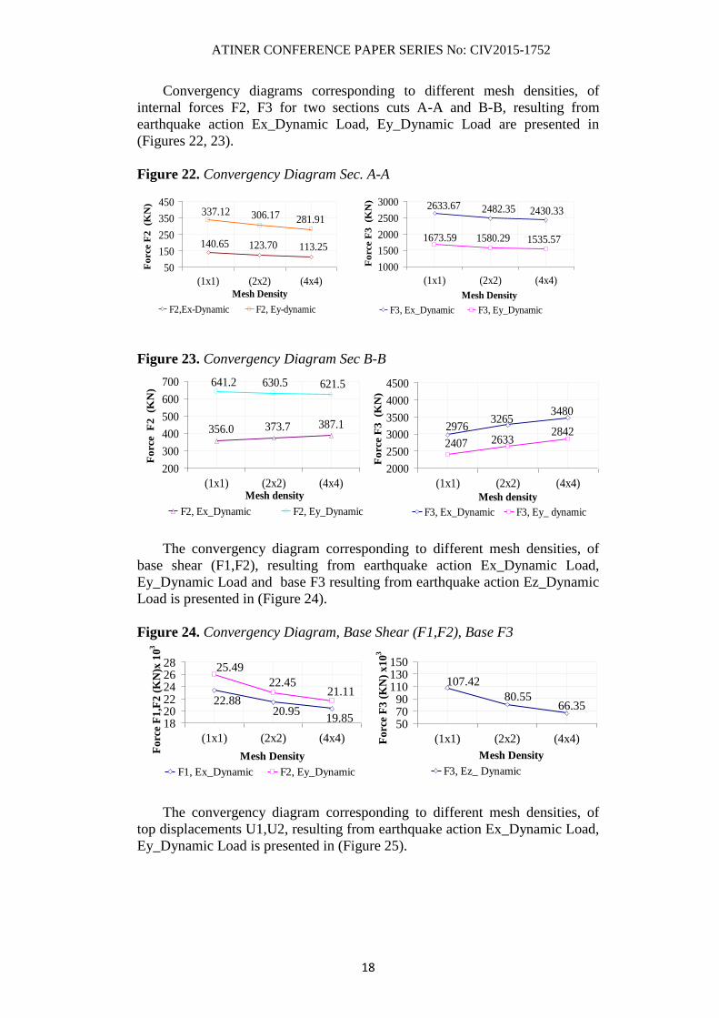
Convergency diagrams corresponding to different mesh densities, of
internal forces F2, F3 for two sections cuts A-A and B-B, resulting from
earthquake action Ex_Dynamic Load, Ey_Dynamic Load are presented in
(Figures 22, 23).
Figure 22. Convergency Diagram Sec. A-A
Figure 23. Convergency Diagram Sec B-B
The convergency diagram corresponding to different mesh densities, of
base shear (F1,F2), resulting from earthquake action Ex_Dynamic Load,
Ey_Dynamic Load and base F3 resulting from earthquake action Ez_Dynamic
Load is presented in (Figure 24).
Figure 24. Convergency Diagram, Base Shear (F1,F2), Base F3
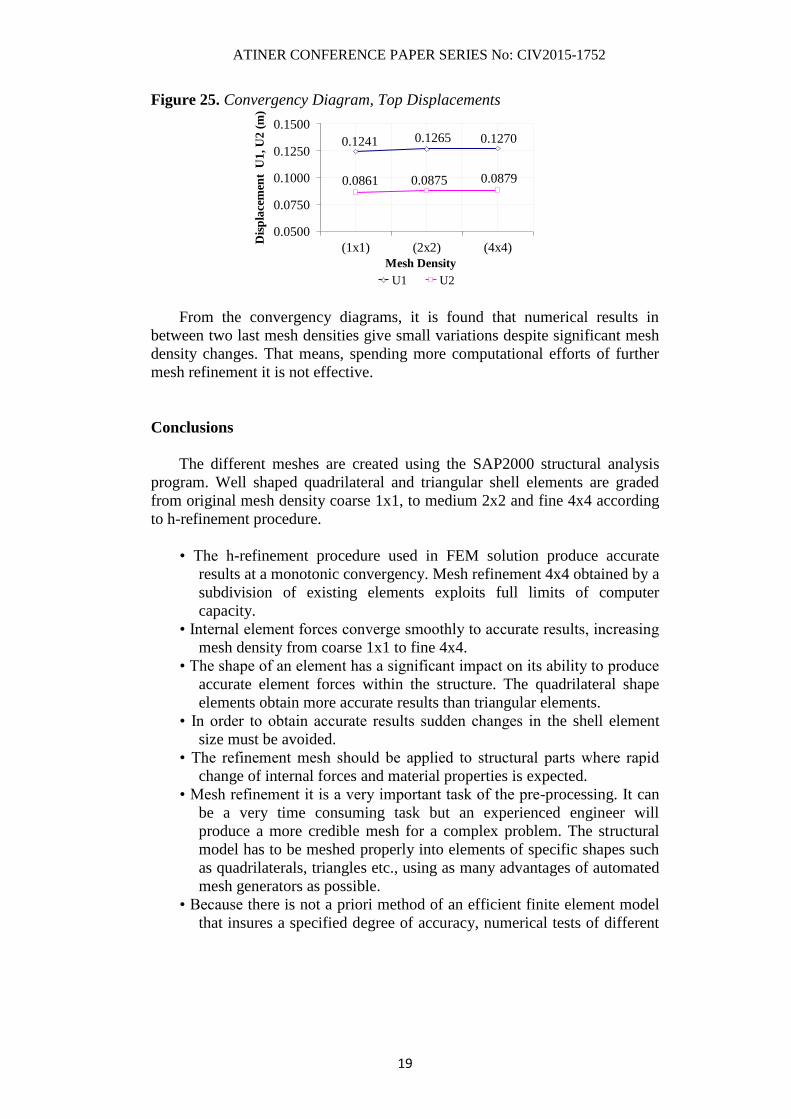
The convergency diagram corresponding to different mesh densities, of
top displacements U1,U2, resulting from earthquake action Ex_Dynamic Load,
Ey_Dynamic Load is presented in (Figure 25).
22.8820.95
19.85
25.49
22.4521.11
182022242628
(1x1) (2x2) (4x4)
Mesh Density
Fo
rce
F1
,F2
(K
N)x
10
3
F1, Ex_Dynamic F2, Ey_Dynamic
107.42
80.5566.35
507090
110130150
(1x1) (2x2) (4x4)
Mesh Density
Fo
rce
F3
(K
N)
x1
03
F3, Ez_ Dynamic
356.0 373.7 387.1
641.2 630.5 621.5
200
300
400
500
600
700
(1x1) (2x2) (4x4)Mesh density
Fo
rce F
2 (K
N)
F2, Ex_Dynamic F2, Ey_Dynamic
34803265
2976 284226332407
2000
2500
3000
3500
4000
4500
(1x1) (2x2) (4x4)Mesh density
Fo
rce F
3 (K
N)
F3, Ex_Dynamic F3, Ey_ dynamic
2430.332482.352633.67
1535.571580.291673.59
1000
1500
2000
2500
3000
(1x1) (2x2) (4x4)
Mesh Density
Fo
rce F
3 (K
N)
F3, Ex_Dynamic F3, Ey_Dynamic
140.65 123.70 113.25
337.12 306.17 281.91
50
150
250
350
450
(1x1) (2x2) (4x4)Mesh Density
Fo
rce F
2 (K
N)
F2,Ex-Dynamic F2, Ey-dynamic
ATINER CONFERENCE PAPER SERIES No: CIV2015-1752
19
Figure 25. Convergency Diagram, Top Displacements
From the convergency diagrams, it is found that numerical results in
between two last mesh densities give small variations despite significant mesh
density changes. That means, spending more computational efforts of further
mesh refinement it is not effective.
Conclusions
The different meshes are created using the SAP2000 structural analysis
program. Well shaped quadrilateral and triangular shell elements are graded
from original mesh density coarse 1x1, to medium 2x2 and fine 4x4 according
to h-refinement procedure.
• The h-refinement procedure used in FEM solution produce accurate
results at a monotonic convergency. Mesh refinement 4x4 obtained by a
subdivision of existing elements exploits full limits of computer
capacity.
• Internal element forces converge smoothly to accurate results, increasing
mesh density from coarse 1x1 to fine 4x4.
• The shape of an element has a significant impact on its ability to produce
accurate element forces within the structure. The quadrilateral shape
elements obtain more accurate results than triangular elements.
• In order to obtain accurate results sudden changes in the shell element
size must be avoided.
• The refinement mesh should be applied to structural parts where rapid
change of internal forces and material properties is expected.
• Mesh refinement it is a very important task of the pre-processing. It can
be a very time consuming task but an experienced engineer will
produce a more credible mesh for a complex problem. The structural
model has to be meshed properly into elements of specific shapes such
as quadrilaterals, triangles etc., using as many advantages of automated
mesh generators as possible.
• Because there is not a priori method of an efficient finite element model
that insures a specified degree of accuracy, numerical tests of different
0.12700.12650.1241
0.08790.08750.0861
0.0500
0.0750
0.1000
0.1250
0.1500
(1x1) (2x2) (4x4)
Mesh DensityD
isp
lace
men
t U
1, U
2 (
m)
U1 U2
ATINER CONFERENCE PAPER SERIES No: CIV2015-1752
20
mesh refinement analyses can be used to assess the solution
convergence.
References
[1] Alan Morris, “A practical Guide to Reliable Finite Element Modelling”, British
Library Cataloguing in Publication Data, p. 143-200, England 2008.
[2] G. R. Liu and S. S. Quek, “The Finite Element Method. A practical course”,
Library of Congress Cataloguing in Publication Data, p 246-256, England 2003.
[3] Robert D. Cook, “Finite Element Modeling for Stress Analysis”, Library of
Congress Cataloguing Data, p 138- 155, England 1995.
[4] Zhu, J. Z.; Hinton, E.; Zienkiewicz, C., "Mesh enrichment against mesh
regeneration using quadrilateral elements", Communications in Numerical
Methods in Engineering, v 9, n 7, Jul 1993, p. 547-554.
[5] Zhu, J. Z., Zienkiewicz, O. C., Hinton, E., and Wu, J., "A New Approach to the
Development of Automatic Quadrilateral Mesh Generation", IJNME, Vol. 32, p.
849-866, 1991.
[6] Lee, C. K. and Hobbs, R. E., "Automatic Adaptive Finite Element Mesh
Generation Over Arbitrary Two-dimensional Domain Using Advancing Front
Technique", Computers and Structures, Vol.71, p. 9-34, 1999.
[7] Lee, C. K. and Hobbs, R. E., “Automatic Adaptive Refinement for Plate Bending
Problems Using Reissner-Mindlin Plate Bending Elements,” International
Journal for in Numerical Methods in Engineering, Vol. 41, p. 1-63, 1998.
[8] Diez, P. and Huerta, A., "A Unified Approach to Remeshing Strategies for Finite
Element h- Adaptivity," Comput. Methods Appl. Mech. Engrg., vol. 176, (1999),
p. 215-229.
[9] Blacker, T. D. and Stevenson, M. B., “Paving: A new approach to automatic
quadrilateral meshing technique,” Advances in Engineering Software, 13(5-
6):811-847, 1991.
[10] Owen, S. J., “A Survey of Unstructured Mesh Generation Technology", The 7th
International Meshing Roundtable, Dearborn, Michigan, October 26 - 28, 1998,
p. 239-267.
[11] Zienkiewicz, O. C and Zhu, J. Z., "A simple Error Estimator and Adaptive
Procedure for Practical Engineering Analysis," Int. J. Numer. Methods Eng., Vol.
24, p. 337-357, 1987.
[12] S. J. Owen, M. L. Staten, S. A. Canann and S. Saigal, "Q -Morph: An Indirect
Approach to Advancing Front Quad Meshing", Int. J. Numer. Meth. Engng., 44,
1317-1340 (1999).
[13] C. K. Lee and S. H. Lo, "A New Scheme for the Generation of a Graded
Quadrilateral Mesh", Comput. Struct., 52, 847-857 (1994).
[14] P. Kinney, "Clean Up: Improving Quadrilateral Finite Element Meshes", Proc.
6th Int. Meshing Roundtable, 1995, 449-461.
Related Documents


