Manual CHALLENGER RS232 rev1.2 en Gecma Components electronic GmbH GEC17500162 [email protected] +49 2237 6996 0 1 ATEX Operating Instructions Interface converter CHALLENGER RS232

Welcome message from author
This document is posted to help you gain knowledge. Please leave a comment to let me know what you think about it! Share it to your friends and learn new things together.
Transcript
Manual CHALLENGER RS232 rev1.2 en Gecma Components electronic GmbH GEC17500162 [email protected]
+49 2237 6996 0 1
ATEX Operating Instructions Interface converter
CHALLENGER RS232
Manual CHALLENGER RS232 rev1.2 en Gecma Components electronic GmbH GEC17500162 [email protected]
+49 2237 6996 0 2
Preface Before starting assembly, please read the complete operating instructions, in particular the chapter “Regulations & notes on general safety of operation” on pages 4 and 5 most attentively. The CHALLENGER RS232 system (consisting of the transmitting unit TCS1 and the receiving unit RSI1i) must principally be installed by qualified personnel only. The EC Type Examination Certificate unconditionally has to be observed.
If you have any questions about or suggestions for this product, please contact: GECMA Components GmbH
Heisenbergstraße 26 – 40 D-50169 Kerpen Tel.: +49 (0)22 37 / 69 96 0 Fax: +49 (0)22 37 / 69 96 99
mailto:[email protected]
Http://www.gecma.com
Trademarks mentioned here: AT, IBM and PS/2 are registered trademarks of the International Business Machines Corporation. Microsoft, Windows and Windows NT are registered trademarks of the Microsoft Corporation. Any further trademarks stated or shown in the text are trademarks of the respective proprietors and recognized as protected.

Manual CHALLENGER RS232 rev1.2 en Gecma Components electronic GmbH GEC17500162 [email protected]
+49 2237 6996 0 3
TABLE OF CONTENTS:
PREFACE ................................................................................................................................................. 2
REGULATIONS & NOTES ON GENERAL SAFETY OF OPERATION ................................................ 4
GENERAL DESCRIPTION ...................................................................................................................... 6
DESCRIPTION: TRANSMITTING ASSEMBLY TCS1I ......................................................................... 7
DESCRIPTION: RECEIVING ASSEMBLY RSI1I.................................................................................... 9
DESCRIPTION: SUPPLY UNIT EBU1I (OPTION) .............................................................................. 11
ASSEMBLY OF THE CHALLENGERS RS232 ..................................................................................... 14
CONNECTION OF THE CHALLENGERS RS232 ................................................................................ 15
CONNECTION OF THE TRANSMITTING ASSEMBLY TCS1I IN THE SAFE AREA ....................... 16
CONNECTION OF THE TRANSMITTING ASSEMBLY RSI1I IN THE HAZARDOUS AREA ......... 17
COMMISSIONING .............................................................................................................................. 18
TECHNICAL PROGRESS / REPAIR, HAZARDOUS SUBSTANCES ................................................. 18
TECHNICAL DATA .............................................................................................................................. 19

Manual CHALLENGER RS232 rev1.2 en Gecma Components electronic GmbH GEC17500162 [email protected]
+49 2237 6996 0 4
Regulations & notes on general safety of operation
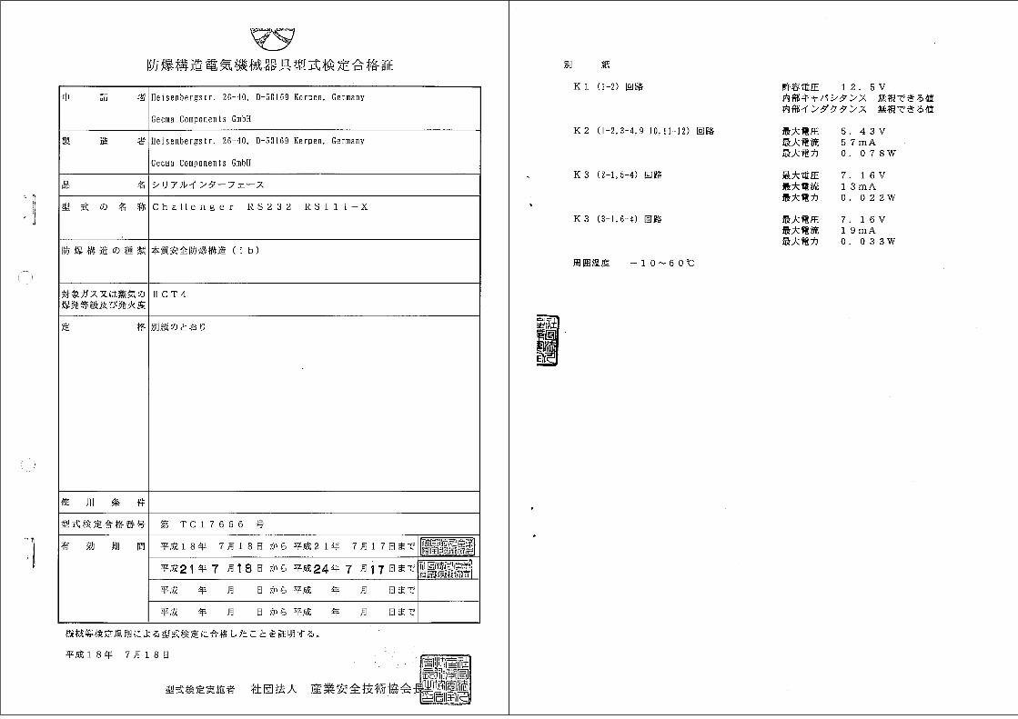
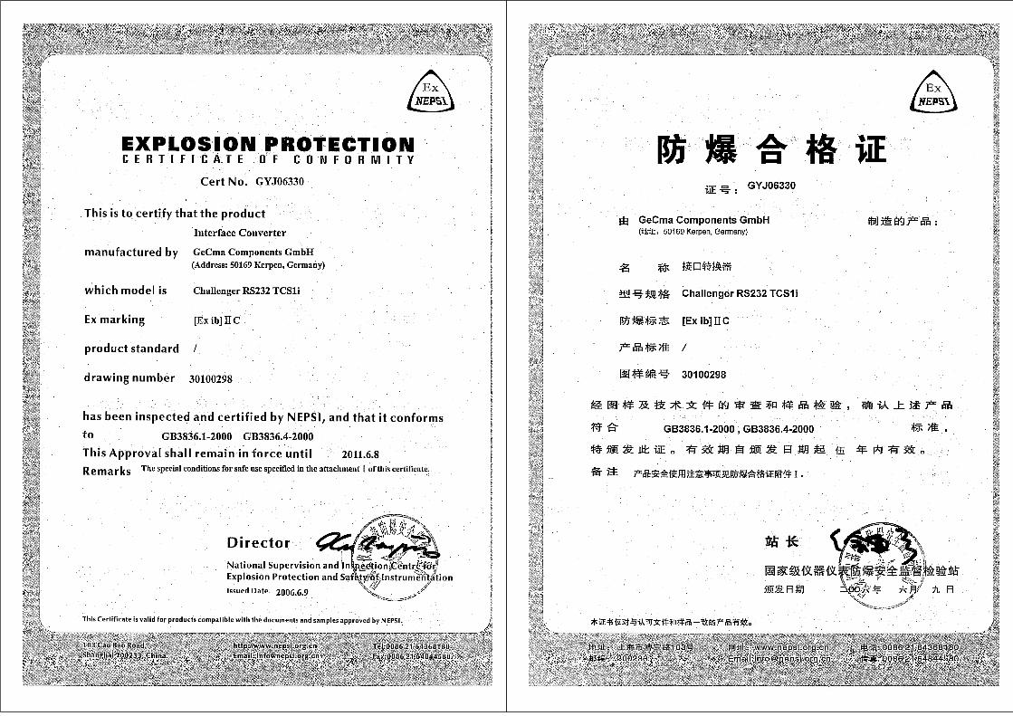
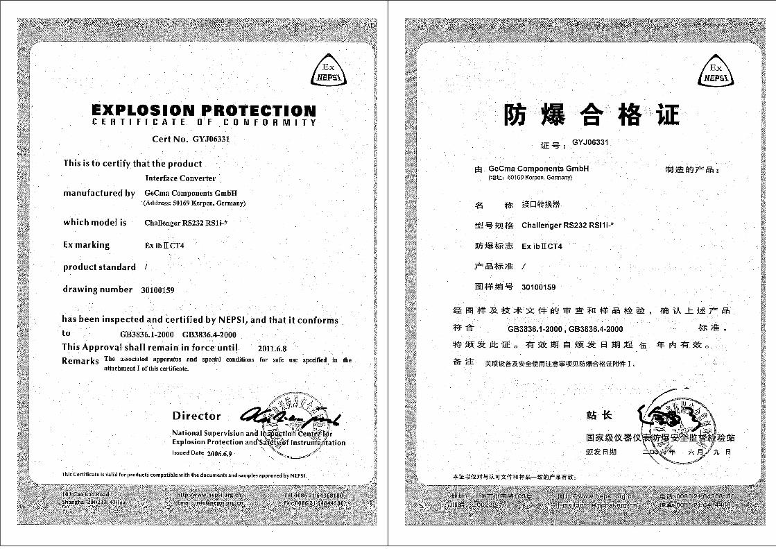
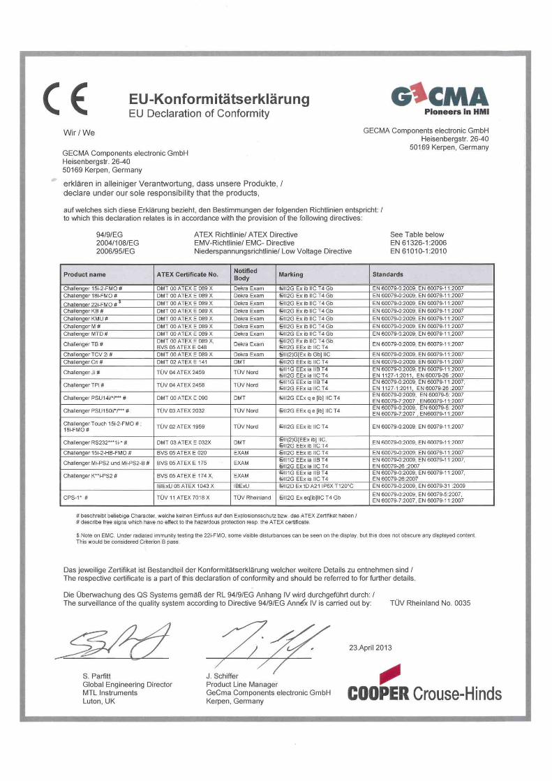
Application The CHALLENGER RS232 system is an intrinsically safe RS232 interface converter for industrial application in hazardous areas of zone 2 and 1. The EC Type Examination Certificate applicable here is: DMT 03 ATEX E 032 X!
Notes on safety The present notes on safety contain information and precautionary notes, which unconditionally have to be considered for a safe mode of operation for the described conditions. Before using the device, please attentively read the operating instructions! In case of doubt (translating errors), the German operating instructions are valid.
Errors and inadmissible loads If it has to be feared that the safety of the device is affected, the device has to be switched-off immediately. Unintentional switching-on again has to be prevented. We recommend sending the device to the manufacturer for examination. The safety of the device may, for example, be endangered when: • Damage is visible at the housing. • The device was exposed to improper loads. • The device was stored improperly. • The device has suffered damages in transport. • The device lettering is illegible. • Mal functions occur. • the admissible limit values were exceeded.
Manual CHALLENGER RS232 rev1.2 en Gecma Components electronic GmbH GEC17500162 [email protected]
+49 2237 6996 0 5
Safety regulations The application of the device requires the observation of the common safety regulations of the user to exclude operating errors at the device. • Use the device for the approved purpose of application only. Damages,
conversions and modifications can invalidate the prescribed explosion protection for the devices and are not admissible. The device must be operated in undamaged and clean condition only. Avoid application in aggressive acids or bases.
• The CHALLENGER RS232 interface converter must be used in zone 1 or/and 2 only, according to the explosion marking from the EC Type Examination Certificate.
• The 19“-slide-in module TCS1i, the chassis as well as their power supply and the computer unit have to be installed outside the hazardous area. The TCS1i slide-in module must only be inserted into the slot provided for that.
• Furthermore, it has to be observed, that the regulations in DIN EN 60079-14, the EC Type Examination Certificate as well as further appropriate standards applicable here are complied with! Therefore, any operational means have to be connected and/or operated correctly and properly. Installation and commissioning must be executed by trained personnel only, who are qualified according to the regulations, standards and guidelines applicable here.
• The devices have to be operated according to the electrical parameters and details specified in the operating instructions & EC Type Examination Certificate. Before putting the device into operation assure, that the device is installed as prescribed and the device and its cabling are not damaged.
• There has to be equipotential bonding between the CHALLENGER RS232 TCS1i and the CHALLENGER RS232 RSI1i (see page: 15). Before any connections are made, execute all grounding measures as well as the equipotential bonding mentioned above. Observe, that the plug at the data cable on the TCS1i side receives the correct coding (see: page 17).
• The highest admissible ambient temperature for the components is -10°C <= Ta <= +60°C
• The national safety and accident prevention regulations as well as the generally accepted engineering rules are applicable. Any further instructions, notes and regulations contained in these operating instructions have to be followed and complied with. Incorrect or inadmissible application as well as non-consideration of the notes of these operating instructions, exclude a guarantee.
On non-consideration of & non-compliance with these chapters, the prescribed explosion protection cannot be guaranteed and there is no claim for guarantee

Manual CHALLENGER RS232 rev1.2 en Gecma Components electronic GmbH GEC17500162 [email protected]
+49 2237 6996 0 6
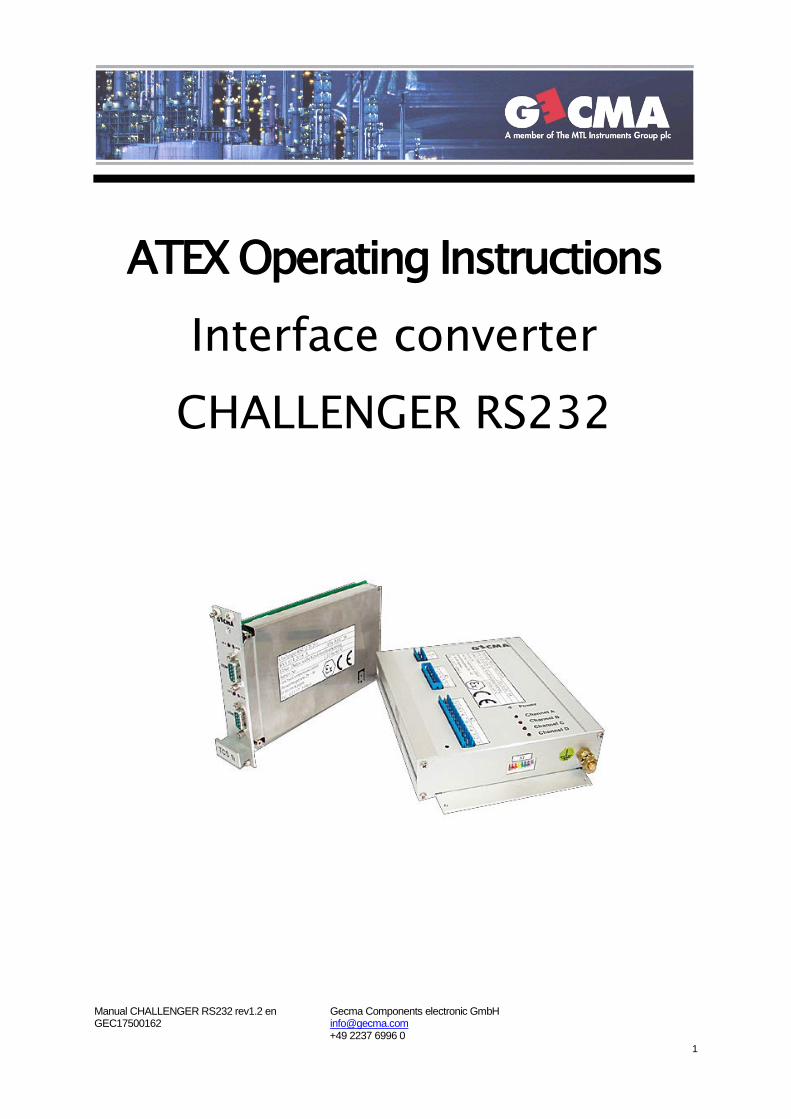
General description The CHALLENGER RS232 system is an additional component to the PC terminal CHALLENGER. This interface converter is capable to transfer RS232 signals from the not hazardous area (e.g. a control station) to the hazardous area (zone 1/ zone 2) and vice versa. In addition, there is the possibility to operate an intrinsically safe RS232 device in the hazardous area with an intrinsically safe supply. The interface converter consists of two sub-units, the transmitting assembly TCS1i and the receiving assembly RSI1i (incl. the additional supply unit EBU1i).
Data line and max. distances For the data transfer, the TCS1i card and the RSI1i card have to be connected with a twisted pair cable from network engineering. The maximum distance is 600 meters for the highest data transfer rate of 38.4 Kb. (For lower transfer rates lengths up to 2000 meters are admissible). The data cable has to fulfill the following requirements: Four-pair data cables with a copper mesh screen and each pair of wires individually screened. For insulation, generally common insulating materials e.g. PE, PCV, etc. are used. In addition to the requirements stated here, the regulations in DIN EN 60079-14 and the following characteristic parameters and values are applicable, too:
Characteristic parameter Value
Loop resistance >15Ω /km Insulation resistance >50MΩ x km
Line capacity <120 nF/km Line inductivity <1400 µH/km
Test voltages wire/wire >1000 Veff
Test voltages wire/screen >500 Veff
Radial insulation thickness wire >0.2 mm Copper diameter of a wire >0.1 mm Lower temperature limit >-100C Upper temperature limit <+ 600C
Maximum length 2000 meters
Variants and versions of the CHALLENGER RS232 Device type: Version:
CHALLENGER RS232 TCS1i Transmitting assembly in the secure area (19“-slide-in module, 6TE)
CHALLENGER RS232 RSI1i-X Transmitting assembly in the hazardous area CHALLENGER RS232 RSI1i-5V1 Transmitting assembly in the hazardous area
with a Zener output voltage of 5.1 volts CHALLENGER RS232 RSI1i-6V8 Transmitting assembly in the hazardous area
with a Zener output voltage of 6.8 volts CHALLENGER RS232 RSI1i-8V2 Transmitting assembly in the hazardous area
with a Zener output voltage of 8.2 volts CHALLENGER RS232 EBU1i-5V1 Supply unit in the hazardous area
with a Zener output voltage of 5.1 volts CHALLENGER RS232 EBU1i-6V8 Supply unit in the hazardous area
with a Zener output voltage of 6.8 volts
Manual CHALLENGER RS232 rev1.2 en Gecma Components electronic GmbH GEC17500162 [email protected]
+49 2237 6996 0 7
CHALLENGER RS232 EBU1i-8V2 Supply unit in the hazardous area with a Zener output voltage of 8.2 volts
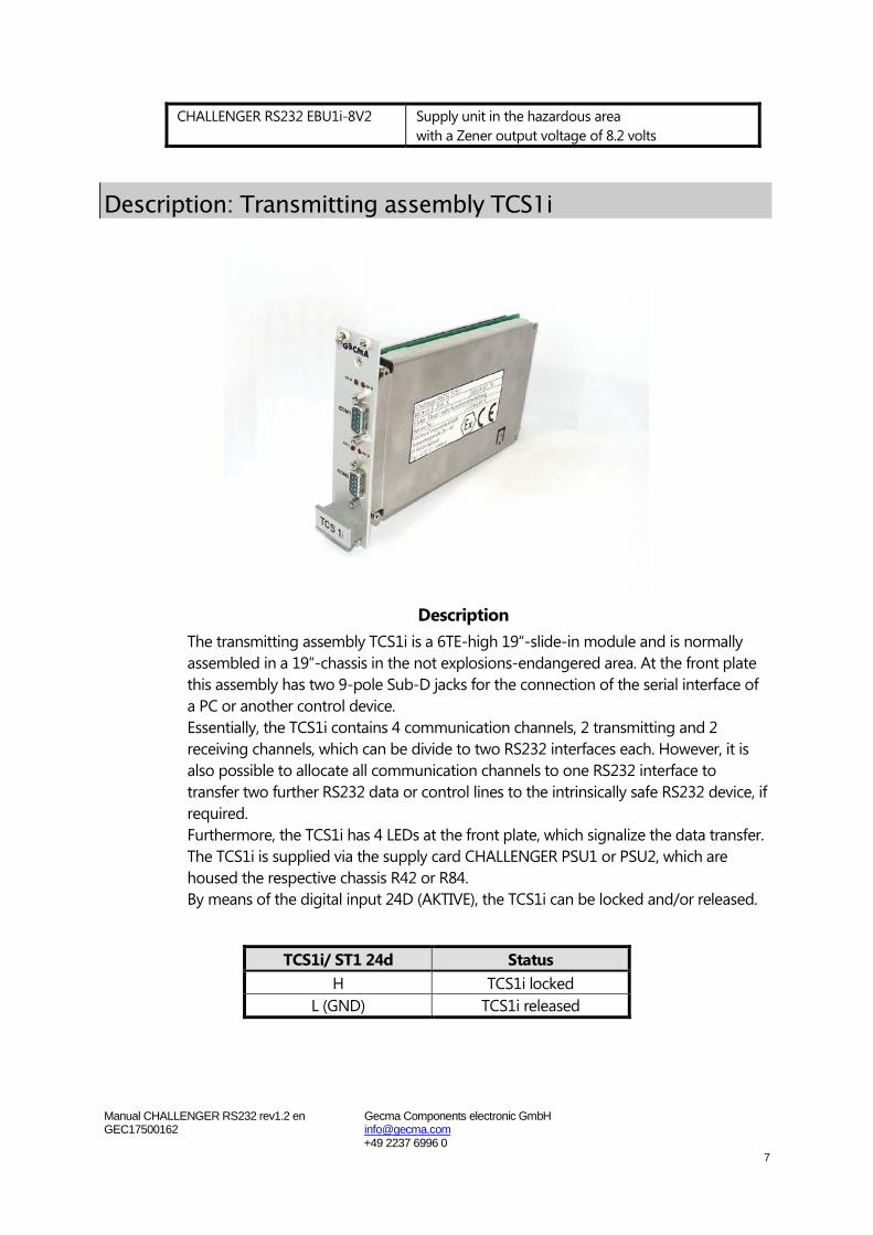
Description: Transmitting assembly TCS1i
Description The transmitting assembly TCS1i is a 6TE-high 19“-slide-in module and is normally assembled in a 19“-chassis in the not explosions-endangered area. At the front plate this assembly has two 9-pole Sub-D jacks for the connection of the serial interface of a PC or another control device. Essentially, the TCS1i contains 4 communication channels, 2 transmitting and 2 receiving channels, which can be divide to two RS232 interfaces each. However, it is also possible to allocate all communication channels to one RS232 interface to transfer two further RS232 data or control lines to the intrinsically safe RS232 device, if required. Furthermore, the TCS1i has 4 LEDs at the front plate, which signalize the data transfer. The TCS1i is supplied via the supply card CHALLENGER PSU1 or PSU2, which are housed the respective chassis R42 or R84. By means of the digital input 24D (AKTIVE), the TCS1i can be locked and/or released.
TCS1i/ ST1 24d Status H TCS1i locked
L (GND) TCS1i released
Manual CHALLENGER RS232 rev1.2 en Gecma Components electronic GmbH GEC17500162 [email protected]
+49 2237 6996 0 8
Technical data: Transmitting assembly TCS1i Designation : CHALLENGER RS232 TCS1i Housing : 19”-slide-in module 3 HE, 6 TE, at least IP20 Voltage supply : +5 and +12 volts via external devices Connections : 2 x RS232 interface with 2 Sub-D 9-pole jacks (COM1 &2)
: supply and data cable connection via 32-pole multipoint plug DIN 41612/ design F/ z+d (ST1) Weight : 400 g Certificate number : DMT 03 ATEX E 032 X Explosion marking : II(2)G [EEx ib] IIC Ambient temperature : -10°C <= Ta <= +60°C
For further characteristic explosion parameters, please refer to the EC Type Examination Certificate (item 15.3)
Occupancy 9-pole sub-D jack COM1
Sub-D jack COM1: Connection: 2 Data line TxD (CH A.) Output 3 Data line RxD (CH B.) Input 5 GND 7 Data line CTS (CH D.) Input1 8 Data line RTS (CH C.) Output1
Occupancy 9-pole sub-D jack COM2
Sub-D jack COM2: Connection: 2 Data line TxD (CH C.) Output 3 Data line RxD (CH D.) Input 5 GND
For further terminal occupancies and terminal diagram: see wiring plan in the Annex!
1 = when COM2 is not required.

Manual CHALLENGER RS232 rev1.2 en Gecma Components electronic GmbH GEC17500162 [email protected]
+49 2237 6996 0 9
Description: Receiving assembly RSI1i
Description
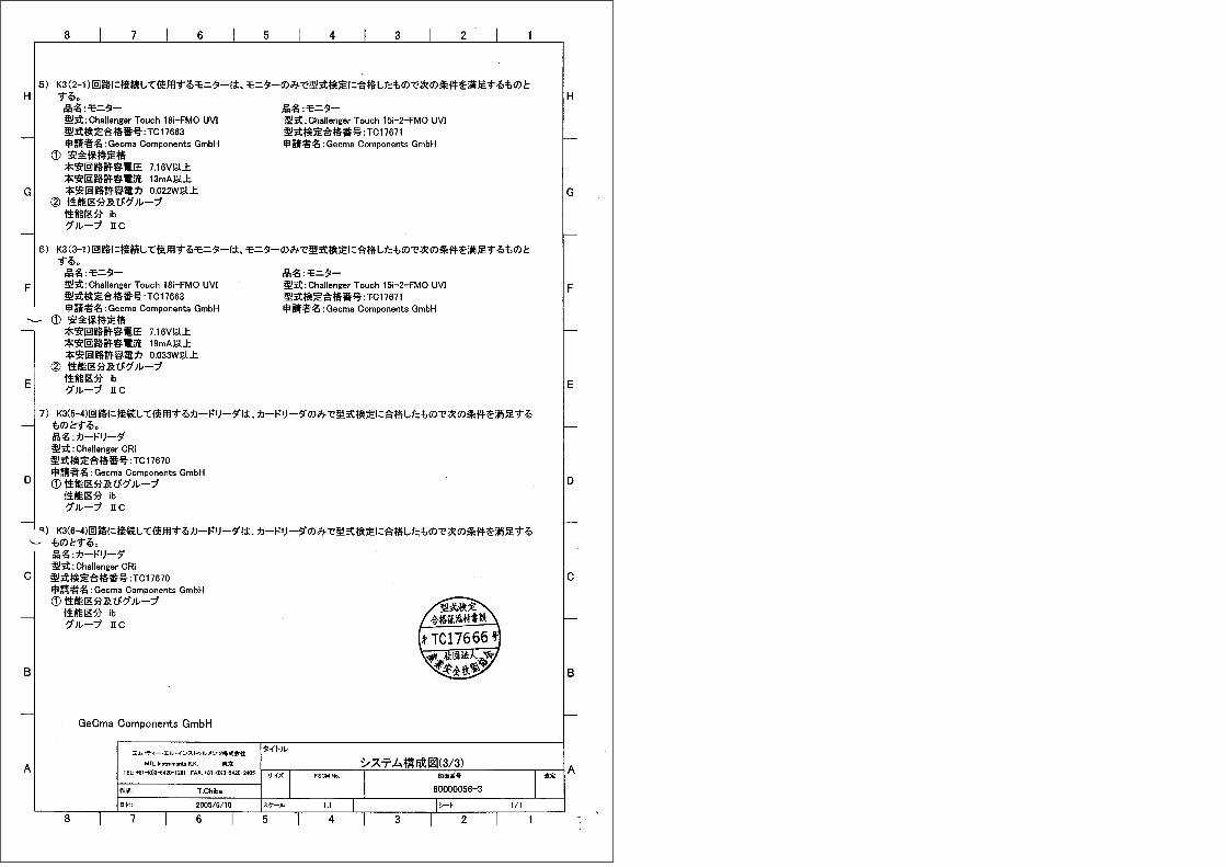
The receiving assembly RSI1i essentially contains a converter card and, if required, an intrinsically safe supply card BCBN2i. The RSI1i is housed in a closed aluminum housing, which is installed in the hazardous area (usually in the CHALLENGER PC terminal). Like the TCS1i, it has 4 communication channels, 2 transmitting and receiving channels each, from which the RS232 data are transmitted to the TCS1i. On the RSI1i there are three plug connectors (K1-3) and 5 LEDs, which signalize the switch-on condition and the data transfer. The RSI1i is usually supplied via the power supply PSU14i or with another suitable supply unit (on agreement with GeCma Components only). As an additional option, the RSI1i-xVx offers the possibility to connect a further RS232-compatible device in the explosion area, which, if required, can be supplied via the optional supply unit (BCBN2i). The output voltages of the BCBN2i can be tapped off at the 16-pole plug connector K4. For a detailed description, please refer chapter: Supply unit BCBN2i, page 11.
Versions: CHALLENGER RS232 RSI1i-X Transmitting assembly in the hazardous area
without the intrinsically safe supply unit “BCBN2i” CHALLENGER RS232 RSI1i-5V1 Transmitting assembly in the hazardous area
with a Zener output voltage of 5.1 volts CHALLENGER RS232 RSI1i-6V8 Transmitting assembly in the hazardous area
with a Zener output voltage of 6.8 volts CHALLENGER RS232 RSI1i-8V2 Transmitting assembly in the hazardous area
with a Zener output voltage of 8.2 volts
Manual CHALLENGER RS232 rev1.2 en Gecma Components electronic GmbH GEC17500162 [email protected]
+49 2237 6996 0 10
RS232 interface converter The RS232 interface converter has the same basic function like the TCS1i. It has 4 communication channels, 2 transmitting and receiving channels each, which transfer the RS232 data to the TCS1i. For signalizing the data transfer, there are 4 red LEDs on the RSI1i, and for signalizing the switch-on condition, there is 1 green LED. By means of the digital input K2/7(AKTIVE), the converter can be locked and/or released.
RSI1/K2-7 Status H Converter locked
L (GND) Converter released (bridge with K2/6(GND) on connector)
Additional supply unit BCBN2i See chapter: Supply unit BCBN2i, page 11
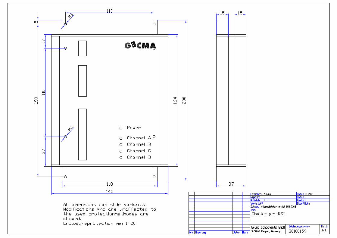
Technical data: Transmitting assembly RSI1i Designation : CHALLENGER RS232 RSI1i Designation : CHALLENGER RS232 RSI1i-5V1/ 6V8/ 8V2 Housing : closed housing Material : aluminum anodized Type of protection : at least IP30 Voltage supply : via CHALLENGER PSU14i or equivalent supplies Connections : K1/ 3-pole Phoenix terminals (supply input)
K2/ 12-pole Phoenix terminals (data cable to TCS1i) K3/ 7-pole Phoenix terminals (intrinsically safe RS232 interface) K4/ 16-pole Phoenix terminals (additional supply for RS232
devices) Dimensions : 125 x 37 x 200 mm (w x h x d) Weight : 800 g Certificate number : DMT 03 ATEX E 032 X Explosion marking : II2G EEx ib IIC T4 Ambient temperature : -10°C <= Ta <= +60°C
For further characteristic explosion parameters, please refer to the EC Type Examination Certificate (item 15.3.2)! Terminal occupancy and terminal diagram: see wiring plan in the Annex
Occupancy 8-fold DIP switch S1 Switch: Description:
1 Activation +V7 2 Activation +V6 3 Activation +V5 4 Activation +V4 5 Activation +V3 6 Activation +V2

Manual CHALLENGER RS232 rev1.2 en Gecma Components electronic GmbH GEC17500162 [email protected]
+49 2237 6996 0 11
7 Activation +V1 8 N.C.
Description: Supply unit EBU1i (Option)
Description The supply unit EBU1i is an additional supply unit for an intrinsically safe device. Like the RSI1i it is housed in a closed aluminum housing (see photograph), with the difference, that in it only one BCBN2i supply unit is installed.
Versions:
Supply unit BCBN2i The supply unit BCBN2i consists of seven Zener barriers, the output voltages of which can be tapped off at the 16-pole connector K4. Zener barriers, which are not required, can be switched off via an 8-fold Dipp switch S1 to not unnecessarily consume power. The BCBN2i is available in 3 versions:
• Zener output voltage of 5.1 volts • Zener output voltage of 6.8 volts • Zener output voltage of 8.2 volts
CHALLENGER RS232 EBU1i-5V1 Transmitting assembly in the hazardous area with a Zener output voltage of 5.1 volts
CHALLENGER RS232 EBU1i-6V8 Transmitting assembly in the hazardous area with a Zener output voltage of 6.8 volts
CHALLENGER RS232 EBU1i-8V2 Transmitting assembly in the hazardous area with a Zener output voltage of 8.2 volts

Manual CHALLENGER RS232 rev1.2 en Gecma Components electronic GmbH GEC17500162 [email protected]
+49 2237 6996 0 12
Basic structure of the BCBN2i
Minimum characteristic parameters of the individual Zener barriers at UK1
=12 V-12.5 V The stated powers & voltages are the electrical values in normal operation. For the maximum characteristic explosion parameters, please refer to the EC Type Examination Certificate (item 15.3.2.3 for RSI1i) or (item 15.3.3.3 for EBU1i)!
Important note before commissioning Before commissioning, it has to be observed, that the characteristic explosion parameters from the EC Type Examination Certificate “CHALLENGER RS232” comply with the characteristic explosion values from the EC Type Examination Certificate of the RS232 device!!
Manual CHALLENGER RS232 rev1.2 en Gecma Components electronic GmbH GEC17500162 [email protected]
+49 2237 6996 0 13
Technical data: Supply unit EBU1i Designation : CHALLENGER RS232 EBU1i-5V1/ 6V8/ 8V2 Housing : closed housing Material : aluminum anodized Type of protection : at least IP30 Voltage supply : via CHALLENGER PSU14i or equivalent supplies Connections : K5/ 3-pole Phoenix terminals (supply input)
K4/ 16-pole Phoenix terminals (additional supply for RS232 devices)
Dimensions : 125 x 37 x 200 mm (w x h x d) Weight : 650 g Certificate number : DMT 03 ATEX E 032 X Explosion marking : II2G EEx ib IIC T4 Ambient temperature : -10°C <= Ta <= +60°C
For further characteristic explosion parameters, please refer to the EC Type Examination Certificate (item 15.3.3.3 for EBU1i)! Terminal occupancy and terminal diagram: see wiring plan in the Annex
Occupancy 8-fold DIP switch S1 Switch: Description:
1 Activation +V7 2 Activation +V6 3 Activation +V5 4 Activation +V4 5 Activation +V3 6 Activation +V2 7 Activation +V1 8 N.C.
Manual CHALLENGER RS232 rev1.2 en Gecma Components electronic GmbH GEC17500162 [email protected]
+49 2237 6996 0 14
Assembly of the CHALLENGERS RS232
General notes on assembly The notes stated in this chapter have to be consistently observed to guarantee a secure and reliable operation.
Furthermore, it has to be considered, that the regulations in DIN EN 60079-14, the EC Type Examination Certificate as well as any further appropriate standards applicable here are complied with.
Please read chapter: “Regulations & notes on general safety of operation“ on pages 4, 5 most attentively.
Assembly of the TCS1i in the safe area The TCS1i card is installed in a chassis provided for that as a standard.
It can, however, also be installed separately into a housing provided by the operator. This housing must have at least IP20 and correspond the regulations in DIN EN 50020, 60079-14, the EC Type Examination Certificate as well as any further appropriate standards applicable here. The TCS1i must be connected with the respective connectors and components only, as it is described in chapter: Description: Transmitting assembly TCS1i (page 7).
The operating means is only fixed with the holes provided for that. Any housing nuts and mounting angles have to be tightened uniformly.
Assembly of the RSI1i unit (or EBU1i unit) in the hazardous area The RSI1i and the EBU1i can be installed in the CHALLENGER terminal or set up as separate, stand-alone units in the hazardous area.
The operating means is only fixed with the holes provided for that. Any housing nuts and mounting angles have to be tightened uniformly.
The maximum admissible ambient temperatures have to be unconditionally observed (see EC Type Examination Certificate).
Manual CHALLENGER RS232 rev1.2 en Gecma Components electronic GmbH GEC17500162 [email protected]
+49 2237 6996 0 15
Connection of the CHALLENGERS RS232
General notes on connection The notes stated in this chapter have to be consistently observed to guarantee a secure and reliable operation. Furthermore, it has to be observed, that the regulations in DIN EN 60079-14, the EC Type Examination Certificate as well as any further appropriate standards applicable here are complied with! Please read chapter: “Regulations & notes on general safety of operation“ on pages 4, 5 most attentively.
Ground conductors must at least have a cross section of 4 mm2, all other cables and lines at least 0.5 mm2!
There has to be equipotential bonding between the TCS1i and the RSI1i. For the TCS1i, this can be applied to the ground pin of the chassis, or for the RCS1i to the ground pin of the RSI housing. The design of the equipotential bonding has to correspond the regulations in DIN EN 60079-14, the EC Type Examination Certificate as well as further appropriate standards and applicable here!
Connection of the data cable between the TCS1i in the safe area and the RSI1i in the hazardous area.
Connect the supplied plug connector to the data line according to the cable plan. Then plug the connectors into the provided terminal strips.

Manual CHALLENGER RS232 rev1.2 en Gecma Components electronic GmbH GEC17500162 [email protected]
+49 2237 6996 0 16
19“-chassis In the explosion area Data cable
Multipoint plug ST1 of the TCS1i
Terminal strip TCS (10-pole)
RSI1i-K2 (12-pole terminal
strip)
Designation Recommended wire color
26D 9 1 1st pair of leads (b) (CH.A) White 26Z 10 2 1st pair of leads (a) (CH.A) Blue 28D 1 3 2nd pair of leads (b) (CH.B) White 28Z 2 4 2nd pair of leads (a) (CH.B) Brown 32D 5 9 3rd pair of leads (b) (CH.C) White 32Z 6 10 3rd pair of leads (a) (CH.C) Orange 30D 3 11 4th pair of leads (b) (CH.D) White 30Z 4 12 4th pair of leads (a) (CH.D) Green 22D 7 5 Screen of the data line Screen 24D 8 - AKTIVE (TCS1i)
(bridge to terminal strip TCS/ Pin7) Black
- - 7 AKTIVE (RSI1)
(bridge to RSI1i-K2/ Pin6) Black
Connection of the transmitting assembly TCS1i in the safe area
General notes on connection The notes stated in this chapter have to be consistently observed to guarantee a secure and reliable operation. Furthermore, it has to be observed, that the regulations in DIN EN 60079-14, the EC Type Examination Certificate as well as any further appropriate standards applicable here are complied with! Please read chapter: “Regulations & notes on general safety of operation“ on pages 4, 5 most attentively.
Installation Insert the TCS1i card & the PSU1 card (alternatively the PSU2 card) into the slots provided for that in the chassis and firmly screw both devices.
Now connect the COM interface of the PC or another control unit with the TCS1i to the COM interface provided for that. Finally, connect the power supply 220 V or 110 V to the 19“-chassis.

Manual CHALLENGER RS232 rev1.2 en Gecma Components electronic GmbH GEC17500162 [email protected]
+49 2237 6996 0 17
Coding of the plug connectors at the chassis On assembly of the 10-pole plug connectors at the chassis it has to be observed, that the coding riders are applied to the correct position to avoid an inadmissible plugging with the terminal strip of the TCV (CHALLENGER terminal).
Connection of the transmitting assembly RSI1i in the hazardous area
General note The notes stated in this chapter have to be consistently observed to guarantee a secure and reliable operation. Furthermore, it has to be observed, that the regulations in DIN EN 60079-14, the EC Type Examination Certificate as well as any further appropriate standards applicable here are complied with! Please read chapter: “Regulations & notes on general safety of operation“ on pages 4, 5 most attentively.
The device must be operated according to the prescribed characteristic parameters only, which can either be taken from the EC Type Examination Certificate or chapter: Description: Receiving assembly RSI1i (page: 9).
Installation
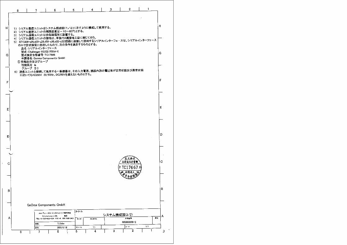
Connect the RSI1i according to the wiring plan (see Annex)!
Connector TCS (CHALLENGER RS232) Connector TCV (CHALLENGER terminal)
Manual CHALLENGER RS232 rev1.2 en Gecma Components electronic GmbH GEC17500162 [email protected]
+49 2237 6996 0 18
Commissioning
General note The notes stated in this chapter have to be consistently observed to guarantee a secure and reliable operation. Furthermore, it has to be observed, that the regulations in DIN EN 60079-14, the EC Type Examination Certificate as well as any further appropriate standards applicable here are complied with! Please read chapter: “Regulations & notes on general safety of operation“ on pages 4, 5 most attentively.
Commissioning Before switching on the plant, check all connections, whether they are correctly and properly connected according to the regulations, standards and provisions prescribed here.
With all connections made correctly, the interface converter CHALLENGER RS232 can be switched on and the PC or the other control unit can be started-up.
To check the correct function of the CHALLENGER RS232 converter, call a program via the PC terminal CHALLENGER at your PC, with which you can test the RS232 system. If the device is working accurately with the PC or the other control unit, the CHALLENGER RS232 interface converter works correctly.
For the optical signalization of the data traffic, the respective LEDs at the TCS1i and/or RSI1i are available.
• Channel A = Interface COM1/ data from TCS1i to RS1i
• Channel B = Interface COM1/ data from RSI1i to TCS1i
• Channel C = Interface COM2/ data from TCS1i to RS1i
• Channel D = Interface COM2/ data from RSI1i to TCS1i
Technical progress / Repair, hazardous substances
Technical progress The manufacturer reserves the right to adjust technical data to development progress without special announcement.

Manual CHALLENGER RS232 rev1.2 en Gecma Components electronic GmbH GEC17500162 [email protected]
+49 2237 6996 0 19
Repair, hazardous substances For all devices sent to the GeCma Components GmbH for repair purposes, an error description has to be enclosed in any case.
The following measures have to be taken, before sending a device for repair: Remove any adhering residues of media. For that, especially observe gasket grooves and
gaps, in which residues of media can be deposited. We must ask you to refrain from sending back a device, when you cannot completely assure, that any noxious substances are completely removed.
Costs, which due to unsatisfactory cleaning of the device arise for a possible disposal or for personal injuries (cauterizations, etc.), are charged to the owner of the device.
Technical data
Technical data: Transmitting assembly TCS1i Designation : CHALLENGER RS232 TCS1i Housing : 19”-slide-in module 3 HE, 6 TE, at least IP20 Voltage supply : +5 and +12 volts via external device Connections : 2 x RS232 interface with 2 Sub-D 9-pole jacks (COM1 &2)
: supply and data cable connection via 32-pole multipoint plug DIN 41612/ design F/ z+d (ST1) Weight : 400 g Certificate number : DMT 02 ATEX XXXX Explosion marking : II(2)G [EEx ib] IIC Ambient temperature : -10°C <= Ta <= +60°C
Technical data: Transmitting assembly RSI1i-5V1/ 6V8/ 8V2 Designation : CHALLENGER RS232 RSI1i Designation : CHALLENGER RS232 RSI1i-5V1/ 6V8/ 8V2
Manual CHALLENGER RS232 rev1.2 en Gecma Components electronic GmbH GEC17500162 [email protected]
+49 2237 6996 0 20
Housing : closed housing Material : aluminum anodized Type of protection : at least IP30 Voltage supply : via CHALLENGER PSU14i or equivalent supplies Connections : K1/ 3-pole Phoenix terminals (supply input)
K2/ 12-pole Phoenix terminals (data cable to the TCS1i) K3/ 7-pole Phoenix terminals (intrinsically safe RS232 interface) K4/ 16-pole Phoenix terminals (additional supply for RS232
devices) Dimensions : 125 x 37 x 200 mm (w x h x d) Weight : 800 g Certificate number : DMT 02 ATEX XXXX Explosion marking : II2G EEx ib IIC T4 Ambient temperature : -10°C <= Ta <= +60°C Technical data: Supply unit EBU1i-5V1/ 6V8/ 8V2 Designation : CHALLENGER RS232 EBU1i-5V1/ 6V8/ 8V2 Housing : closed housing Material : aluminum anodized Type of protection : at least IP30 Voltage supply : via CHALLENGER PSU14i or equivalent supplies Connections : K5/ 3-pole Phoenix terminals (supply input)
K4/ 16-pole Phoenix terminals (additional supply for RS232 devices)
Dimensions : 125 x 37 x 200 mm (w x h x d) Weight : 650 g Certificate number : DMT 02 ATEX XXXX Explosion marking : II2G EEx ib IIC T4 Ambient temperature : -10°C <= Ta <= +60°C


Translation
Page 1 of 6 to DMT 03 ATEX E 032 X This certificate may only be reproducted in its entirety and without change
Am Technologiepark 1, 45307 Essen, telephone +49 (201)172-1416, telefax +49 (201)172-1716
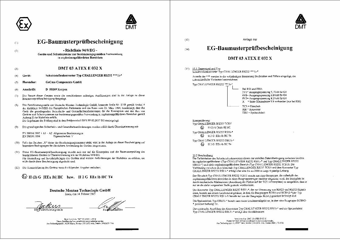
(1) EC Type Examination Certificate(2) - Directive 94/9/EG -
Equipment and protective systems intended for use in potentially explosive atmosphere
(3) DMT 03 ATEX E 032 X (4) Equipment: Interface converter type CHALLENGER RS232 ***1i-*
(5) Manufacturer: GeCma Components GmbH
(6) Address: D 50169 Kerpen
(7) The design of this device as well as the various admissible versions are determined in the annex to this type examination certificate.
(8) The certification office of the Deutsche Montan Technologie GmbH, named office no. 0158 according to article 9 of the directive 94/9/EG of the European Parliament and the Council of March 23rd, 1994, certifies, that the device fulfills the fundamental safety and health requirements for the conception and construction of devices and protective systems for utilization as directed in explosion-endangered areas according to annex II of the directive.
The results of the examination are laid down in the inspection record BVS PP 03.2017 EG.
(9) The basic safety and health requirements are fulfilled by compliance with
EN 50014:1997 + A1 – A2 General provisions EN 50020:1994 Intrinsic Safety ´i´
(10) In case the character “X” follows the certificate number, the annex to this certificate refers to special conditions for the safe application of the device.
(11) This EC type examination certificate relates to the conception and the type examination of the described device in compliance with the directive 94/9/EG only.
For manufacturing and putting into circulation of the device, further requirements of the directive have to be fulfilled, which are not covered by this certificate.
(12) The marking of the device has to contain the following data:
II (2) G [EEx ib] IIC resp. II 2 G EEx ib IIC T4
Deutsche Montan Technologie GmbH Essen, February 14th, 2003
_________________________ ___________________________ DMT certification body Head of special services unit
Translation
Page 2 of 6 to DMT 03 ATEX E 032 X This certificate may only be reproducted in its entirety and without change
Am Technologiepark 1, 45307 Essen, telephone +49 (201)172-1416, telefax +49 (201)172-1716
(13) Annex to
(14) EC Type Examination Certificate
DMT 03 ATEX E 032 X (15) 15.1 Equipment and type Interface converter type CHALLENGER RS232 ***1i-*
Instead of ***, characters and figures are included in the complete denomination, which identify the different versions:
Type CHALLENGER RS232 ***1i-*
For RSI and EBU: 5V1 = output voltage 5.1 volt for K4 6V8 = output voltage 6.8 volt for K4 8V2 = output voltage 8.2 volt for K4 X = no terminal board K4 existent (for RSI only)
TCS = plug-in unit RSI = converter EBU = feed unit
Marking: Type CHALLENGER RS232 TCS1i
II (2) G [EEx ib] IIC
Type CHALLENGER RS232 RSI1i-* II 2 G EEx ib IIC T4
Type CHALLENGER RS232 EBU1i-* II 2 G EEx ib IIC T4
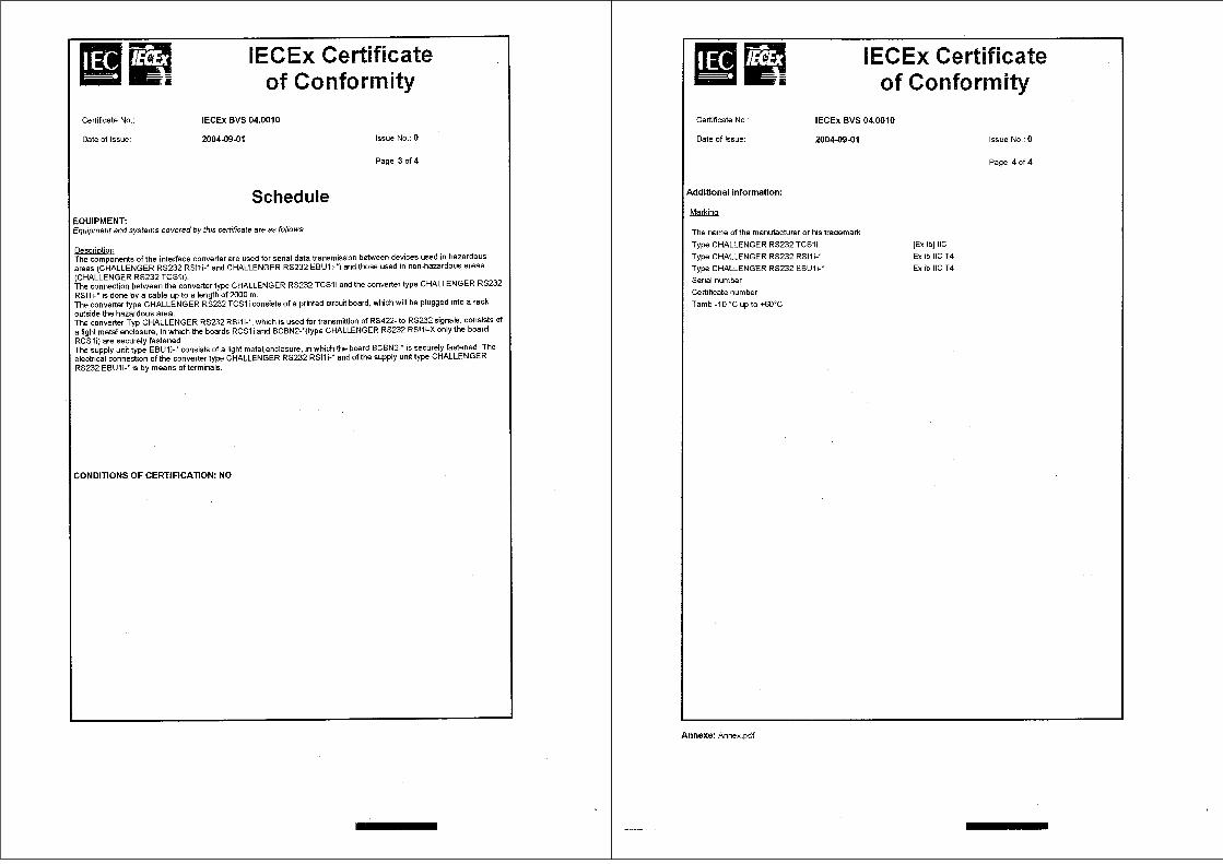
15.2 DescriptionThe sub-units of the interface converter serve the serial data transmission between devices in the explosion-endangered (type CHALLENGER RS232 RSI1i-* and type CHALLENGER RS232 EBU1i-*) and non-explosion-endangered area (type CHALLENGER RS232 TCS1i). The connection between the plug-in unit type CHALLENGER RS232 TCS1i and the converter type CHALLENGER RS232 RSI1i-* is made via an up to 2000-m-long 4-pair line.
The plug-in unit type CHALLENGER RS232 TCS1i consists of an assembly, which is applied outside the explosion-endangered area, pluggable in a chassis; by mechanical measures (arrangement of the board on the TCS1i front plate), the slot is set up that way, that it can only be plugged at the position provided for that.
The converter type CHALLENGER RS232 RSI1i-*, which serves the conversion of RS422 to RS232 signals, consists of a light metal housing, in which the assemblies RCS1i and BCBN2-* (the type CHALLENGER RS232 RSI1i-X consists of the assembly RCS1i only) are securedly fixed.
The feed unit type EBU1i-* consists of a light metal housing, in which an assembly BCBN2-* is securedly fixed.
The electrical connection of the converter type CHALLENGER RS232 RSI1i-* and the feed unit type CHALLENGER RS232 EBU1i-* is made via plug clamps.
Translation
Page 3 of 6 to DMT 03 ATEX E 032 X This certificate may only be reproducted in its entirety and without change
Am Technologiepark 1, 45307 Essen, telephone +49 (201)172-1416, telefax +49 (201)172-1716
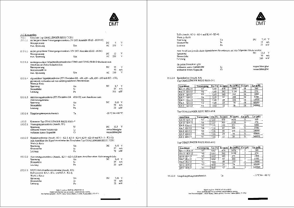
15.3 Parameters15.3.1 Plug in unit type CHALLENGER RS232 TCS1i 15.3.1.1 non intrinsically safe power supply circuit 5V (ST1 contacts d8/z8 – d10/z10)
Power Supply Voltage DC 5 V Max.voltage Um AC 250 V
15.3.1.2 non intrinsically safe power supply circuit 12V (ST1 contacts d2/z2 – d4/z4) Power Supply Voltage DC 12 V Max.voltage Um AC 250 V
15.3.1.3 non intrinsically safe interface circuits COM1 and COM2 (SUB-D-connector) to connect on data interfaces Rated voltage DC 15 V Rated current 50 mA Max.voltage Um AC 250 V
15.3.1.4 intrinsically safe signal circuits (ST1 contacts d26 – z26, d28 – z28, d30 – z30 and d32 – z32), galvanically adjunctive with non intrinsically safe circuits value per circuit Voltage Uo DC 6,7 V Current Io 85 mA Power Po 311 mW
15.3.1.5 Activation circuit (ST1 contacts d24 – d22/z22) to connect with a activation link Voltage Uo DC 5,43 V Current Io 39 mA Power Po 53 mW
15.3.1.6 Ambient temperature range Ta -10 °C until + 60 °C
15.3.2 Converter type CHALLENGER RS232 RSI1i-* 15.3.2.1 Power supply circuit (terminal K1)
Voltage Ui DC 12,5 V max internal inductance Li negligible max internal capacitance Ci negligible
15.3.2.2 Signal circuits (terminals K2-1 – K2-2, K2-3 – K2-4, K2-9 – K2-10 and K2-11 – K2-12) to connect with the signal circuits form the plug in unit type CHALLENGER RS232 TCS1i value per circuit Voltage Uo DC 5,43 V Current Io 57 mA Power Po 78 mW
15.2.2.2 Activation circuit (terminal K2-7 – K2-5,6,8) to connect with a activation link Voltage Uo DC 5,43 V Current Io 39 mA Power Po 53 mW
15.2.2.3 RS232-Interface circuits (terminal K3) RxD (terminal K3-2 – K3-1 and K3-5 – K3-4) value per circuit Voltage Uo DC 7,16 V Current Io 13 mA Power Po 22 mW
Translation
Page 4 of 6 to DMT 03 ATEX E 032 X This certificate may only be reproducted in its entirety and without change
Am Technologiepark 1, 45307 Essen, telephone +49 (201)172-1416, telefax +49 (201)172-1716
TxD (terminal K3-3 – K3-1 and K3-6 – K3-4) value per circuit Voltage Uo DC 7,16 V Current Io 19 mA Power Po 33 mW
to connect in each case a circuit with the following maximum values: Voltage DC 12,5 V Current 30 mA Power 200 mW
for every circuit apply: max internal inductance Li negligible max internal capacitance Ci negligible
15.3.2.3 power supply circuits (terminal K4) Typ CHALLENGER RS232 RSI1i-5V1
Terminal Power supply Uo (V) Io (mA) Po (mW) Co (µF) Lo (µH) K4-13 -K4-15 V7 5,43 470 1444 58 160 K4-11 -K4-15 V6 5,43 362 1114 58 270 K4-9 - K4-15 V5 5,43 183 565 58 1000 K4-7 - K4-15 V4 5,43 97 299 58 3700 K4-5 - K4-15 V3 5,43 49 152 58 14000 K4-3 - K4-15 V2 5,43 24 74 58 60000 K4-1 - K4-15 V1 5,43 12 38 58 240000
Typ CHALLENGER RS232 RSI1i-6V8
Terminal Power supply Uo (V) Io (mA) Po (mW) Co (µF) Lo (µH) K4-13 -K4-15 V7 7,32 470 1470 11 160 K4-11 -K4-15 V6 7,32 362 1130 11 270 K4-9 -K4-15 V5 7,32 183 571 11 1000 K4-7 -K4-15 V4 7,32 97 303 11 3700 K4-5 -K4-15 V3 7,32 49 153 11 14000 K4-3 -K4-15 V2 7,32 24 74 11 60000 K4-1 -K4-15 V1 7,32 12 38 11 240000
Typ CHALLENGER RS232 RSI1i-8V2
Terminal Power supply Uo (V) Io (mA) Po (mW) Co (µF) Lo (µH) K4-13 -K4-15 V7 8,82 470 1470 5 160 K4-11 -K4-15 V6 8,82 362 1130 5 270 K4-9 -K4-15 V5 8,82 183 571 5 1000 K4-7 -K4-15 V4 8,82 97 303 5 3700 K4-5 -K4-15 V3 8,82 49 153 5 14000 K4-3 -K4-15 V2 8,82 24 74 5 60000 K4-1 -K4-15 V1 8,82 12 38 5 240000
15.3.1.6 mbient temperature range Ta -10 °C until + 60 °C

Translation
Page 5 of 6 to DMT 03 ATEX E 032 X This certificate may only be reproducted in its entirety and without change
Am Technologiepark 1, 45307 Essen, telephone +49 (201)172-1416, telefax +49 (201)172-1716
15.3.3 Feed unit type CHALLENGER RS232 EBU1i-* 15.3.3.1 Power supply circuit (terminal K5)
Voltage Ui DC 12,5 V max internal inductance Li negligible max internal capacitance Ci negligible
15.3.3.3 Power supply circuits (terminal K4) Typ CHALLENGER RS232 EBU1i-5V1
Terminal Power supply Uo (V) Io (mA) Po (mW) Co (µF) Lo (µH) K4-13 -K4-15 V7 5,43 470 1444 58 160 K4-11 -K4-15 V6 5,43 362 1114 58 270 K4-9 - K4-15 V5 5,43 183 565 58 1000 K4-7 - K4-15 V4 5,43 97 299 58 3700 K4-5 - K4-15 V3 5,43 49 152 58 14000 K4-3 - K4-15 V2 5,43 24 74 58 60000 K4-1 - K4-15 V1 5,43 12 38 58 240000
Typ CHALLENGER RS232 EBU1i-6V8
Terminal Power supply Uo (V) Io (mA) Po (mW) Co (µF) Lo (µH) K4-13 -K4-15 V7 7,32 470 1470 11 160 K4-11 -K4-15 V6 7,32 362 1130 11 270 K4-9 -K4-15 V5 7,32 183 571 11 1000 K4-7 -K4-15 V4 7,32 97 303 11 3700 K4-5 -K4-15 V3 7,32 49 153 11 14000 K4-3 -K4-15 V2 7,32 24 74 11 60000 K4-1 -K4-15 V1 7,32 12 38 11 240000
Typ CHALLENGER RS232 EBU1i-8V2
Terminal Power supply Uo (V) Io (mA) Po (mW) Co (µF) Lo (µH) K4-13 -K4-15 V7 8,82 470 1470 5 160 K4-11 -K4-15 V6 8,82 362 1130 5 270 K4-9 -K4-15 V5 8,82 183 571 5 1000 K4-7 -K4-15 V4 8,82 97 303 5 3700 K4-5 -K4-15 V3 8,82 49 153 5 14000 K4-3 -K4-15 V2 8,82 24 74 5 60000 K4-1 -K4-15 V1 8,82 12 38 5 240000
15.3.1.6 Ambient temperature range Ta -10 °C until + 60 °C
Translation
Page 6 of 6 to DMT 03 ATEX E 032 X This certificate may only be reproducted in its entirety and without change
Am Technologiepark 1, 45307 Essen, telephone +49 (201)172-1416, telefax +49 (201)172-1716
15.3.4 For the data cable between the plug-in unit CHALLENGER RS232 TCS1i and the converter type CHALLENGER RS232 RSI1i-* applies the following: Loop resistance > 15 /km Insulation resistance > 50 M x km Line capacity < 120 nF/km Line inductivity < 1400 µH/km Test voltage wire/wire > 1000 Veff Test voltage wire/shield > 500 Veff Radial insulation thickness wire > 0.2 mm Copper diameter of a wire > 0.1 mm Application temperature range -10°C to +60°C Max. length 2000 meters
(16) Inspection report BVS PP 03.2017 EG, issue 14.02.2003
(17) Special conditions for safe application17.1 The plug-in type CHALLENGER RS232 TCS1i is to be installed outside the explosion-
endangered area into a housing, which guarantees the degree of protection IP 20.
17.2 The connection parts for the external inherently safe power circuits of the plug-in unit type CHALLENGER RS232 TCS1i have to be arranged that way, that the blank parts have a distance of at least 50 mm from connection parts or blank conductors of non-inherently safe power circuits or are separated by a separating wall according to 6.4.1 of EN 50020:1994.
17.3 Between the plug-in unit type CHALLENGER RS232 TCS1i and the converter type CHALLENGER RS232 RSI1i-* equipotential bonding has to be established.


Related Documents