Welcome message from author
This document is posted to help you gain knowledge. Please leave a comment to let me know what you think about it! Share it to your friends and learn new things together.
Transcript


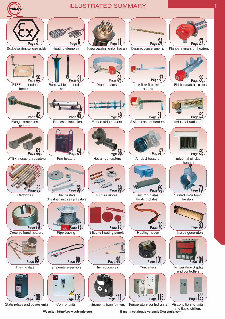
ILLUSTRATED SUMMARY
Screw plug immersion heaters Flange Immersion heaters
Flange immersion heaters
Removable immersionheaters
PTFE immersionheaters
Drum heaters Fluid circulation heaters
Page11
Page 42
Page 31Page 29 Page 34 Page 38
Explosive atmospheres guidePage 3
Ceramic core elementsPage 24
Industrial radiatorsPage 52
Page 27
Process circulationPage 45
Finned strip heatersPage 49
Switch cabinet heatersPage 51
Heating elementsPage 6
Low flow fluid inlineheaters
Page 37
1
Pipe tracing Silicone heating panels
ATEX industrial radiators
Cartridges Sealed mica bandheaters
PTC resistorsPage 70Page 69
Cast iron platesHeating plates
Page 69
Industrial air ductheaters
Ceramic band heaters
Fan heaters Air duct heaters
Page 70
Page57 Page 59
Infrared generatorsPage 80Page 76Page 72 Page 78
Heating hoses
Page 63
Hot air generatorsPage 56Page 53
Disc heatersSheathed mica strip heaters
Page 68
Page 54
Website : http://www.vulcanic.com E-mail : [email protected]
Temperature control unitsInstruments transformersPage 115
State relays and power unitsPage 106
Control unitsPage 108 Page 122
Air conditioning unitsand liquid chillers
Page 111
Thermostats Temperature sensors Thermocouples Converters Temperature displayand controllers
Page 90 Page 90Page 85 Page104Page 101
TABLE OF CONTENTS2
VULCANIC ATEX OFFER 3BASICS ABOUT ATEX EXPLOSION PROOF PROTECTION 4-5
HEATING ELEMENTS 6-8HEATING ELEMENTS SQUARE-SECTION HEATING ELEMENT 9
IMMERSION HEATERS 10-12SCREW PLUG IMMERSION HEATERS 131”1/2 SCREW PLUG IMMERSION HEATERS 14-18SCREW PLUG IMMERSION HEATERS ACCESSORIES 19M 45 SCREW PLUG IMMERSION HEATERS 20-21M 77 SCREW PLUG IMMERSION HEATERS 22-23CERAMIC CORE ELEMENTS ACCESSORIES FOR M 45 & M77 IMMERSION HEATERS 24ACCESSORIES FOR M45 & M77 IMMERSION HEATERS 25VULCALOY® IMMERSION HEATERS 26LOW POWER FLANGE IMMERSION HEATERS 27-28PTFE IMMERSION HEATERS 29-30REMOVABLE IMMERSION HEATERS 31-33DRUM HEATERS 34-35FLUID CIRCULATION HEATERS 36-41FLANGE IMMERSION HEATERS TYPE 2006 UP TO DN 700 42EXPLOSION PROTECTION TYPES OF FLANGE IMMERSION HEATERS 43PROTECTION TYPES OF IMMERSION HEATERS 44HIGH FLUX HEATERS TYPE COMPATHERM 45PROCESS CIRCULATION HEATERS 46-47
TWISTED FINNED ELEMENTS 49FINNED STRIP HEATERS 50ANTI-CONDENSATION CABINET HEATERS 51RADIATORS 52EXPLOSION-PROOF RADIATORS 53FAN HEATERS 54FAN HEATERS CONVECTOR HEATERS – HOT AIR CURTAINS 55HOT AIR GENERATORS 56DUCT AIR HEATERS 57-58INDUSTRIAL AIR DUCT HEATERS 59-60AIR OR GAS HEATERS 61VULSTAR ® CARTRIDGES 63VULSTAR ® CARTRIDGE HEATERS 64-66VULSTAR ® ACCESSORIES 67DISC HEATERS AND STRIP HEATERS 68PTC RESISTORS AND HEATING PLATES 69BAND HEATERS 70-71PIPE TRACING 72-74ATEX PIPE TRACING 75SILICONE HEATING PANELS 76-77HEATING HOSES 78-79INDUSTRIAL INFRARED GENERATORS 80-82NFRARED HEATING FOR PEOPLE 83
THERMOSTATS AND SAFETY TEMPERATURE CUT-OUTS 85-88ELECTRO-MECHANICAL THERMOSTATS 89SELECTING A TEMPERATURE SENSOR 90-91TEMPERATURE PROBES 92-96THERMOCOUPLES 97-99ACCESSORIES FOR TEMPERATURE PROBES 100CONVERTERS AND MEASUREMENT UNITS 101TUBES OR PROBES SEALING 102-103TEMPERATURE CONTROLLERS 104TEMPERATURE DISPLAYS AND CONTROLLERS 105SOLID STATE RELAYS 106POWER UNITS 107READY TO USE POWER SUPPLY & CONTROL UNITS 108-109
LOW AND MEDIUM INSTRUMENT TRANSFORMERS 111TRANSFORMERS 112
INSULATION AND CONNECTION ACCESSORIES 113
VULCATHERM® : TEMPERATURE CONTROL UNITS 114-120AIR CONDITIONING UNITS AND LIQUID CHILLERS 121
Website : http://www.vulcanic.com E-mail : [email protected] : http://www.vulcanic.com E-mail : [email protected]
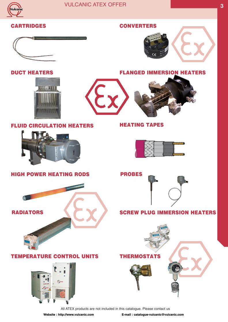
VULCANIC ATEX OFFER
SCREW PLUG IMMERSION HEATERS
CONVERTERS
HIGH POWER HEATING RODS PROBES
RADIATORS
DUCT HEATERS
THERMOSTATS
SELF-CONTROLLED HEATING ELEMENT
HEATING TAPES
FLANGED IMMERSION HEATERS
FLUID CIRCULATION HEATERS
TEMPERATURE CONTROL UNITS
CARTRIDGES
All ATEX products are not included in this catalogue. Please contact us
3
Website : http://www.vulcanic.com E-mail : [email protected]
BASICS ABOUT ATEX EXPLOSION PROOFPROTECTION
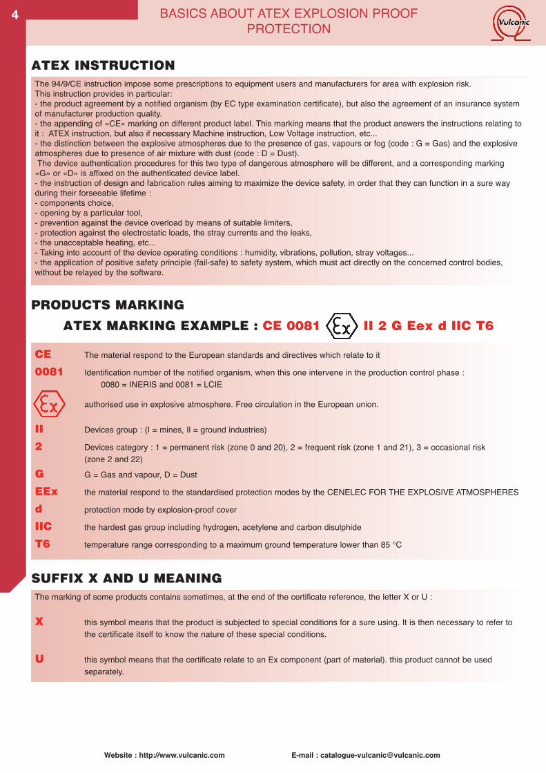
The 94/9/CE instruction impose some prescriptions to equipment users and manufacturers for area with explosion risk.This instruction provides in particular:- the product agreement by a notified organism (by EC type examination certificate), but also the agreement of an insurance systemof manufacturer production quality.- the appending of «CE» marking on different product label. This marking means that the product answers the instructions relating toit : ATEX instruction, but also if necessary Machine instruction, Low Voltage instruction, etc...- the distinction between the explosive atmospheres due to the presence of gas, vapours or fog (code : G = Gas) and the explosiveatmospheres due to presence of air mixture with dust (code : D = Dust).The device authentication procedures for this two type of dangerous atmosphere will be different, and a corresponding marking«G» or «D» is affixed on the authenticated device label.- the instruction of design and fabrication rules aiming to maximize the device safety, in order that they can function in a sure wayduring their forseeable lifetime :- components choice,- opening by a particular tool,- prevention against the device overload by means of suitable limiters,- protection against the electrostatic loads, the stray currents and the leaks,- the unacceptable heating, etc...- Taking into account of the device operating conditions : humidity, vibrations, pollution, stray voltages...- the application of positive safety principle (fail-safe) to safety system, which must act directly on the concerned control bodies,without be relayed by the software.
CE The material respond to the European standards and directives which relate to it
0081 Identification number of the notified organism, when this one intervene in the production control phase :0080 = INERIS and 0081 = LCIE
authorised use in explosive atmosphere. Free circulation in the European union.
II Devices group : (I = mines, Il = ground industries)
2 Devices category : 1 = permanent risk (zone 0 and 20), 2 = frequent risk (zone 1 and 21), 3 = occasional risk(zone 2 and 22)
G G = Gas and vapour, D = Dust
EEx the material respond to the standardised protection modes by the CENELEC FOR THE EXPLOSIVE ATMOSPHERES
d protection mode by explosion-proof cover
IIC the hardest gas group including hydrogen, acetylene and carbon disulphide
T6 temperature range corresponding to a maximum ground temperature lower than 85 °C
ATEX INSTRUCTION
PRODUCTS MARKING
The marking of some products contains sometimes, at the end of the certificate reference, the letter X or U :
X this symbol means that the product is subjected to special conditions for a sure using. It is then necessary to refer tothe certificate itself to know the nature of these special conditions.
U this symbol means that the certificate relate to an Ex component (part of material). this product cannot be usedseparately.
SUFFIX X AND U MEANING
ATEX MARKING EXAMPLE : CE 0081 II 2 G Eex d IIC T6
4
Website : http://www.vulcanic.com E-mail : [email protected]
BASICS ABOUT ATEX EXPLOSION PROOFPROTECTION
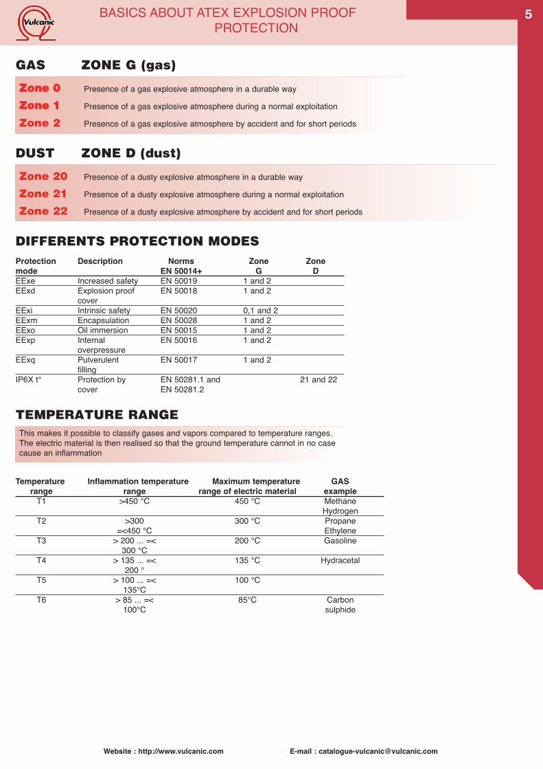
Zone 20 Presence of a dusty explosive atmosphere in a durable way
Zone 21 Presence of a dusty explosive atmosphere during a normal exploitation
Zone 22 Presence of a dusty explosive atmosphere by accident and for short periods
This makes it possible to classify gases and vapors compared to temperature ranges.The electric material is then realised so that the ground temperature cannot in no casecause an inflammation
DIFFERENTS PROTECTION MODES
TEMPERATURE RANGE
Protection Description Norms Zone Zonemode EN 50014+ G DEExe Increased safety EN 50019 1 and 2EExd Explosion proof EN 50018 1 and 2
coverEExi Intrinsic safety EN 50020 0,1 and 2EExm Encapsulation EN 50028 1 and 2EExo Oil immersion EN 50015 1 and 2EExp Internal EN 50016 1 and 2
overpressureEExq Pulverulent EN 50017 1 and 2
fillingIP6X t° Protection by EN 50281.1 and 21 and 22
cover EN 50281.2
GAS ZONE G (gas)
DUST ZONE D (dust)
ZZoonnee 00 Presence of a gas explosive atmosphere in a durable way
ZZoonnee 11 Presence of a gas explosive atmosphere during a normal exploitation
Zone 2 Presence of a gas explosive atmosphere by accident and for short periods
Temperature Inflammation temperature Maximum temperature GASrange range range of electric material exampleT1 >450 °C 450 °C Methane
Hydrogen T2 >300 300 °C Propane
=<450 °C EthyleneT3 > 200 ... =< 200 °C Gasoline
300 °CT4 > 135 ... =< 135 °C Hydracetal
200 °T5 > 100 ... =< 100 °C
135°CT6 > 85 ... =< 85°C Carbon
100°C sulphide
5
6
Website : http://www.vulcanic.com E-mail : [email protected]
HEATING ELEMENTS
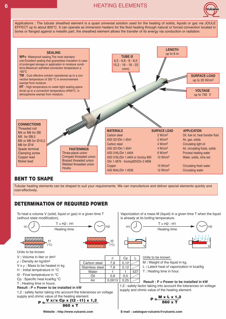
Applications : The tubular sheathed element is a quasi universal solution used for the heating of solids, liquids or gaz via JOULEEFFECT up to about 800°C. It can operate as immersion heaters for the fluid heating through natural or forced convection located inbores or flanged against a metallic part, the sheathed element allows the transfer of its energy via conduction or radiation.
BENT TO SHAPE
TUBE Ø6,5 - 6,8 - 8 - 8,510,2 - 16 - 18 - 22
(mm)
FASTENINGSThree-piece unionCrimped threaded unionBrazed threaded unionWelded threaded unionHooks
SURFACE LOADup to 20 W/cm2
LENGTHup to 6 mSEALING
WP+: Waterproof sealing.The most standardone.Excellent sealing that guarantees insulation in caseof prolonged storage or application in moisture condi-tions.Maximum admitted connection temperature a160°CTM : Cost effective solution operational up to a con-nection temperature of 350 °C in environnementexempt from moistureHT : High temperature,no water-tight sealing,opera-tional up to a connection temperature of450°C, inatmospheres exempt from moisture.
CONNECTIONSThreaded rodM4 or M6 for Ø8M5 for Ø8,5M5 or M6 for Ø10,2M6 for Ø16Spade terminalClamping screwCopper leadNickel lead
Tubular heating elements can be shaped to suit your requirements. We can manufacture and deliver special elements quickly andcost-effectively.
MATERIALS SURFACE LOAD APPLICATIONCarbon steel 2 W/cm2 Oil, fuel oil, heat transfer fluidAISI 321/Din 1.4541 2 W/cm2 Air, gas, solidsCarbon steel 4 W/cm2 Circulating light oilAISI 321/Din 1.4541 4 W/cm2 Air, circulating fluids, solidsAISI 316L/Din 1.4404 6 W/cm2 Process heating waterAISI 316L/Din 1.4404 or Incoloy 800 10 W/cm2 Water, solids, infra red/Din 1.4876 - Incoloy825/Din 2.4858Copper 10 W/cm2 Circulating fresh waterAISI 904L/Din 1.4539 12 W/cm2 Circulating water
VOLTAGEup to 750 V
To heat a volume V (solid, liquid or gas) in a given time T(without state modification).
Vaporization of a mass M (liquid) in a given time T when the liquidis already at its boiling temperature.
V : Volume in liter or dm3Units to be known
ρ : Density en kg/dm3V x ρ : Mass to be heated in kgt1 : Initial température in °Ct2 : Final température in °CCp : Specific heat kcal/kg.°CT : Heating time in hours.
1,2 : safety factor taking into account the tolerances on voltagesupply and ohmic value of the heating element.
Result : P = Power to be installed in kW
P = V x x Cp x (t2 - t1) x 1,2860 x T
T = H2 - H1Heating time
V V VV
H1 H2T = H2 - H1Heating timeH1 H2
M : Weight of the liquid in kg.Units to be known
L : Latent heat of vaporization in kcal/kgT : Heating time in hour.
P = M x L x 1,2 860 x T
CpCarbon steel
Stainless steelWater
OilAir
7,87,81
0,90,0013
0,12ρ L
0,121
0,50,25
537
t1(°C)
t2(°C)
1,2 : safety factor taking into account the tolerances on voltagesupply and ohmic value of the heating element.
Result : P = Power to be installed in kW
ρ
DETERMINATION OF REQUIRED POWER
7
Website : http://www.vulcanic.com E-mail : [email protected]
HEATING ELEMENTS
M M ML
B
C C C C C C1
B B B B
C2
1 n spires
L L L M
40
C
O
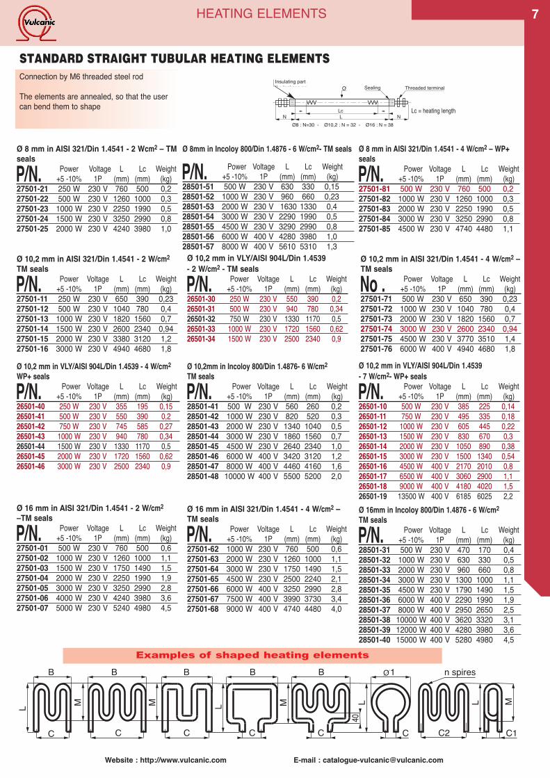
Examples of shaped heating elements
Connection by M6 threaded steel rod
The elements are annealed, so that the usercan bend them to shape VVV VVV
Lc= =LN N
Sealing Threaded terminalInsulating part allowingthe leakage path
Ø8 : N=30 - Ø10,2 : N = 32 - Ø16 : N = 38
O
Ø 16 mm in AISI 321/Din 1.4541 - 2 W/cm2–TM seals
P/N. Power Voltage L Lc Weight+5 -10% 1P (mm) (mm) (kg)
27501-01 500 W 230 V 760 500 0,627501-02 1000 W 230 V 1260 1000 1,127501-03 1500 W 230 V 1750 1490 1,527501-04 2000 W 230 V 2250 1990 1,927501-05 3000 W 230 V 3250 2990 2,827501-06 4000 W 230 V 4240 3980 3,627501-07 5000 W 230 V 5240 4980 4,5
Ø 10,2 mm in AISI 321/Din 1.4541 - 2 W/cm2TM seals
P/N. Power Voltage L Lc Weight+5 -10% 1P (mm) (mm) (kg)
27501-11 250 W 230 V 650 390 0,2327501-12 500 W 230 V 1040 780 0,427501-13 1000 W 230 V 1820 1560 0,727501-14 1500 W 230 V 2600 2340 0,9427501-15 2000 W 230 V 3380 3120 1,227501-16 3000 W 230 V 4940 4680 1,8
Ø 16 mm in AISI 321/Din 1.4541 - 4 W/cm2 –TM seals
P/N. Power Voltage L Lc Weight+5 -10% 1P (mm) (mm) (kg)
27501-62 1000 W 230 V 760 500 0,627501-63 2000 W 230 V 1260 1000 1,127501-64 3000 W 230 V 1750 1490 1,527501-65 4500 W 230 V 2500 2240 2,127501-66 6000 W 400 V 3250 2990 2,827501-67 7500 W 400 V 3990 3730 3,427501-68 9000 W 400 V 4740 4480 4,0
Ø 10,2 mm in VLY/AISI 904L/Din 1.4539- 2 W/cm2 - TM seals
P/N. Power Voltage L Lc Weight+5 -10% 1P (mm) (mm) (kg)
26501-30 250 W 230 V 550 390 0,226501-31 500 W 230 V 940 780 0,3426501-32 750 W 230 V 1330 1170 0,526501-33 1000 W 230 V 1720 1560 0,6226501-34 1500 W 230 V 2500 2340 0,9
Ø 10,2 mm in AISI 321/Din 1.4541 - 4 W/cm2 –TM seals
No . Power Voltage L Lc Weight+5 -10% 1P (mm) (mm) (kg)
27501-71 500 W 230 V 650 390 0,2327501-72 1000 W 230 V 1040 780 0,427501-73 2000 W 230 V 1820 1560 0,727501-74 3000 W 230 V 2600 2340 0,9427501-75 4500 W 230 V 3770 3510 1,427501-76 6000 W 400 V 4940 4680 1,8
Ø 8 mm in AISI 321/Din 1.4541 - 2 Wcm2 – TMseals
P/N. Power Voltage L Lc Weight+5 -10% 1P (mm) (mm) (kg)
27501-21 250 W 230 V 760 500 0,227501-22 500 W 230 V 1260 1000 0,327501-23 1000 W 230 V 2250 1990 0,527501-24 1500 W 230 V 3250 2990 0,827501-25 2000 W 230 V 4240 3980 1,0
STANDARD STRAIGHT TUBULAR HEATING ELEMENTS
Ø 8 mm in AISI 321/Din 1.4541 - 4 W/cm2 – WP+seals
P/N. Power Voltage L Lc Weight+5 -10% 1P (mm) (mm) (kg)
27501-81 500 W 230 V 760 500 0,227501-82 1000 W 230 V 1260 1000 0,327501-83 2000 W 230 V 2250 1990 0,527501-84 3000 W 230 V 3250 2990 0,827501-85 4500 W 230 V 4740 4480 1,1
Ø 10,2 mm in VLY/AISI 904L/Din 1.4539 - 4 W/cm2WP+ seals
P/N. Power Voltage L Lc Weight+5 -10% 1P (mm) (mm) (kg)
26501-40 250 W 230 V 355 195 0,1526501-41 500 W 230 V 550 390 0,226501-42 750 W 230 V 745 585 0,2726501-43 1000 W 230 V 940 780 0,3426501-44 1500 W 230 V 1330 1170 0,526501-45 2000 W 230 V 1720 1560 0,6226501-46 3000 W 230 V 2500 2340 0,9
Ø 16mm in Incoloy 800/Din 1.4876 - 6 W/cm2TM seals
P/N. Power Voltage L Lc Weight+5 -10% 1P (mm) (mm) (kg)
28501-31 500 W 230 V 470 170 0,428501-32 1000 W 230 V 630 330 0,528501-33 2000 W 230 V 960 660 0,828501-34 3000 W 230 V 1300 1000 1,128501-35 4500 W 230 V 1790 1490 1,528501-36 6000 W 400 V 2290 1990 1,928501-37 8000 W 400 V 2950 2650 2,528501-38 10000 W 400 V 3620 3320 3,128501-39 12000 W 400 V 4280 3980 3,628501-40 15000 W 400 V 5280 4980 4,5
Ø 10,2mm in Incoloy 800/Din 1.4876- 6 W/cm2TM seals
P/N. Power Voltage L Lc Weight+5 -10% 1P (mm) (mm) (kg)
28501-41 500 W 230 V 560 260 0,228501-42 1000 W 230 V 820 520 0,328501-43 2000 W 230 V 1340 1040 0,528501-44 3000 W 230 V 1860 1560 0,728501-45 4500 W 230 V 2640 2340 1,028501-46 6000 W 400 V 3420 3120 1,228501-47 8000 W 400 V 4460 4160 1,628501-48 10000 W 400 V 5500 5200 2,0
Ø 10,2 mm in VLY/AISI 904L/Din 1.4539- 7 W/cm2- WP+ seals
P/N. Power Voltage L Lc Weight+5 -10% 1P (mm) (mm) (kg)
26501-10 500 W 230 V 385 225 0,1426501-11 750 W 230 V 495 335 0,1826501-12 1000 W 230 V 605 445 0,2226501-13 1500 W 230 V 830 670 0,326501-14 2000 W 230 V 1050 890 0,3826501-15 3000 W 230 V 1500 1340 0,5426501-16 4500 W 400 V 2170 2010 0,826501-17 6500 W 400 V 3060 2900 1,126501-18 9000 W 400 V 4180 4020 1,526501-19 13500 W 400 V 6185 6025 2,2
Ø 8mm in Incoloy 800/Din 1.4876 - 6 W/cm2- TM seals
P/N. Power Voltage L Lc Weight+5 -10% 1P (mm) (mm) (kg)
28501-51 500 W 230 V 630 330 0,1528501-52 1000 W 230 V 960 660 0,2328501-53 2000 W 230 V 1630 1330 0,428501-54 3000 W 230 V 2290 1990 0,528501-55 4500 W 230 V 3290 2990 0,828501-56 6000 W 400 V 4280 3980 1,028501-57 8000 W 400 V 5610 5310 1,3
Lc = heating length
Website : http://www.vulcanic.com E-mail : [email protected] : http://www.vulcanic.com E-mail : [email protected]
VVVLc
Ø
LN
VVV
C
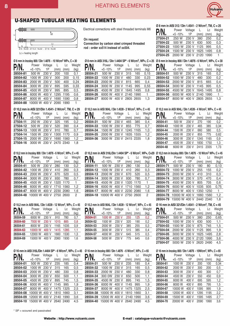
Ø 8 : N=30 - Ø 10,2 : N=32 - Ø 16 : N=38
U-SHAPED TUBULAR HEATING ELEMENTS
On requestConnection by carbon steel crimped threadedrod : order xx514 instead of xx504.
* SP = scoured and passivated
Ø 16mm inAISI 316L/Din 1.4404 SP* - 6W/cm2,WP+, C = 45
P/N. Power Voltage L Lc Weight+5 -10% 1P (mm) (mm) (kg)
28504-01 500 W 230 V 235 185 0,428504-02 1000 W 230 V 315 165 0,528504-03 2000 W 230 V 480 330 0,828504-04 3000 W 230 V 650 500 1,128504-05 4500 W 230 V 895 745 1,528504-06 6000 W 400 V 1145 995 1,928504-07 8000 W 400 V 1475 1325 2,528504-08 10000 W 400 V 1810 1660 3,128504-09 12000 W 400 V 2140 1990 3,628504-10 15000 W 400 V 2640 2490 4,5
Ø 16mm inAISI 321/Din 1.4541 - 2 W/cm2, TM, C = 45
P/N. Power Voltage L Lc Weight+5 -10% 1P (mm) (mm) (kg)
27504-01 500 W 230 V 380 250 0,6527504-02 1000 W 230 V 630 500 1,127504-03 1500 W 230 V 875 745 1,527504-04 2000 W 230 V 1125 995 1,927504-05 3000 W 230 V 1625 1495 2,827504-06 4000 W 230 V 2120 1990 3,627504-07 5000 W 230 V 2620 2490 4,5
Ø 16mm in Incoloy 800 / Din 1.4876 - 6 W/cm2, WP+, C = 65
P/N. Power Voltage L Lc Weight+5 -10% 1P (mm) (mm) (kg)
28504-31 500 W 230 V 235 185 0,428504-32 1000 W 230 V 315 165 0,528504-33 2000 W 230 V 480 330 0,828504-34 300 0W 230 V 650 500 1,128504-35 4500 W 230 V 895 745 1,528504-36 6000 W 400 V 1145 995 1,928504-37 8000 W 400 V 1475 1325 2,528504-38 10000 W 400 V 1810 1660 3,128504-39 12000 W 400 V 2140 1990 3,628504-40 15000 W 400 V 2640 2490 4,5
Ø 10,2 mm inAISI 316L/Din 1.4404 SP* - 6 W/cm2, WP+, C=29
P/N. Power Voltage L Lc Weight+5 -10% 1P (mm) (mm) (kg)
28504-11 500 W 230 V 280 130 0,228504-12 1000 W 230 V 410 260 0,328504-13 2000 W 230 V 670 520 0,528504-14 3000 W 230 V 930 780 0,728504-15 4500 W 230 V 1320 1170 128504-16 6000 W 400 V 1710 1560 1,228504-17 8000 W 400 V 2230 2080 1,628504-18 10000 W 400 V 2750 2600 2
Ø 10,2 mm inAISI 321/Din 1.4541- 2 W/cm2, TM, C = 29
P/N. Power Voltage L Lc Weight+5 -10% 1P (mm) (mm) (kg)
27504-11 250 W 230 V 325 195 0,227504-12 500 W 230 V 520 390 0,427504-13 1000 W 230 V 910 780 0,727504-14 1500 W 230 V 1300 1170 0,927504-15 2000 W 230 V 1690 1560 1,227504-16 3000 W 230 V 2470 2340 1,8
Ø 10,2 mm in AISI 904L / Din 1.4539 - 2 W/cm2, WP+, C = 45
P/N. Power Voltage L Lc Weight+5 -10% 1P (mm) (mm) (kg)
26504-31 500 W 230 V 465 385 0,426504-33 1000 W 230 V 855 775 0,726504-34 1500 W 230 V 1245 1165 1,026504-35 2000 W 230 V 1635 1555 1,226504-36 3000 W 230 V 2415 2335 1,8
Ø 10,2 mm in Incoloy 800 / Din 1.4876 - 6 W/cm2, WP+, C = 45
P/N. Power Voltage L Lc Weight+5 -10% 1P (mm) (mm) (kg)
28504-41 500 W 230 V 280 130 0,228504-42 1000 W 230 V 410 260 0,328504-43 2000 W 230 V 670 520 0,528504-44 3000 W 230 V 930 780 0,728504-45 4500 W 230 V 1320 1170 128504-46 6000 W 400 V 1710 1560 1,228504-47 8000 W 400 V 2230 2080 1,628504-48 10000 W 400 V 2750 2600 2
Ø 8mm inAISI 316L / Din 1.4404 SP* - 6 W/cm2, WP+, C = 25
P/N. Power Voltage L Lc Weight+5 -10% 1P (mm) (mm) (kg)
28504-21 500 W 230 V 315 165 0,1528504-22 1000 W 230 V 480 330 0,2328504-23 2000 W 230 V 815 665 0,428504-24 3000 W 230 V 1145 995 0,5528504-25 4500 W 230 V 1645 1495 0,828504-26 6000 W 400 V 2140 1990 128504-27 8000 W 400 V 2805 2655 1,3
Ø 8mm inAISI 312 / Din 1.4541 - 2 W/cm2, TM, C = 25
P/N. Power Voltage L Lc Weight+5 -10% 1P (mm) (mm) (kg)
27504-21 250 W 230 V 380 250 0,227504-22 500 W 230 V 630 500 0,327504-23 1000 W 230 V 1125 995 0,527504-24 1500 W 230 V 1625 1495 0,827504-25 2000 W 230 V 2120 1990 1Ø 8mm in Incoloy 800 / Din 1.4876 - 6 W/cm2, WP+, C = 30
P/N. Power Voltage L Lc Weight+5 -10% 1P (mm) (mm) (kg)
28504-51 500 W 230 V 315 165 0,228504-52 1000 W 230 V 480 330 0,228504-53 2000 W 230 V 815 665 0,428504-54 3000 W 230 V 1145 995 0,528504-55 4500 W 230 V 1645 1495 0,828504-56 6000 W 400 V 2140 1990 128504-57 8000 W 400 V 2805 2655 1,3
Ø 10,2 mm in AISI 904L / Din 1.4539 - 4 W/cm2, WP+, C = 45
P/N. Power Voltage L Lc Weight+5 -10% 1P (mm) (mm) (kg)
26504-41 500 W 230 V 270 190 0,226504-43 1000 W 230 V 465 385 0,3426504-44 1500 W 230 V 660 580 0,526504-45 2000 W 230 V 855 775 0,6226504-46 3000 W 230 V 1245 1165 0,926504-47 4500 W 230 V 1830 1750 1,326504-48 6000 W 230 V 2415 2335 1,73
Ø 16mm in Incoloy 800 / Din 1.4876 - 10W/cm2, WP+, C = 65
P/N. Power Voltage L Lc Weight+5 -10% 1P (mm) (mm) (kg)
28504-61 1000 W 230 V 200 100 0,3428504-62 2000 W 230 V 300 200 0,528504-63 3000 W 230 V 400 300 0,728504-64 4500 W 230 V 550 450 0,928504-65 6000 W 400 V 695 595 1,228504-66 8000 W 400 V 895 795 1,528504-67 10000 W 400 V 1095 995 1,928504-68 12000 W 400 V 1295 1195 2,228504-69 15000 W 400 V 1595 1495 2,728504-70 20000 W 400 V 2090 1990 3,6
Ø 10,2 mm in Incoloy 800 / Din 1.4876 - 10W/cm2 WP+, C = 45
P/N. Power Voltage L Lc Weight+5 -10% 1P (mm) (mm) (kg)
28504-71 500 W 230 V 180 80 0,1328504-72 1000 W 230 V 255 155 0,228504-73 2000 W 230 V 410 310 0,328504-74 3000 W 230 V 570 470 0,428504-75 4500 W 230 V 805 705 0,628504-76 6000 W 400 V 1035 935 0,7528504-77 8000 W 400 V 1350 1250 128504-78 10000 W 400 V 1660 1560 1,228504-79 15000 W 400 V 2440 2340 1,8
Ø 8mm in Incoloy 800 / Din 1.4876 - 10W/cm2 WP+, C = 30
P/N. Power Voltage L Lc Weight+5 -10% 1P (mm) (mm) (kg)
28504-81 500 W 230 V 200 100 0,128504-82 1000 W 230 V 300 200 0,1528504-83 2000 W 230 V 500 400 0,2428504-84 3000 W 230 V 695 595 0,3328504-85 4500 W 230 V 995 895 0,528504-86 6000 W 400 V 1295 1195 0,628504-87 8000 W 400 V 1690 1590 0,828504-88 10000 W 400 V 2090 1990 1
Ø 10,2 mm in AISI 904L / Din 1.4539 - 12 W/cm2, WP+, C = 45
P/N. Power Voltage L Lc Weight+5 -10% 1P (mm) (mm) (kg)
26504-51 1000 W 230 V 255 125 0,226504-52 1500 W 230 V 320 190 0,226504-53 2000 W 230 V 385 255 0,326504-55 3000 W 230 V 515 385 0,426504-57 4000 W 230 V 645 515 0,526504-58 5000 W 230 V 775 645 0,6
Ø 10,2 mm in AISI 904L / Din 1.4539 - 12 W/cm2, WP+, C = 45
P/N. Power Voltage L Lc Weight+5 -10% 1P (mm) (mm) (kg)
26504-59 6000 W 230 V 910 780 0,726504-60 7000 W 230 V 1015 885 0,826504-61 8000 W 230 V 1165 1035 0,926504-63 10000 W 400 V 1415 1285 1,126504-65 12000 W 400 V 1660 1530 1,326504-69 15000 W 400 V 2060 1930 1,6
HEATING ELEMENTS
Electrical connections with steel threaded terminals M6
8
Lc = heating length
9
Website : http://www.vulcanic.com E-mail : [email protected]
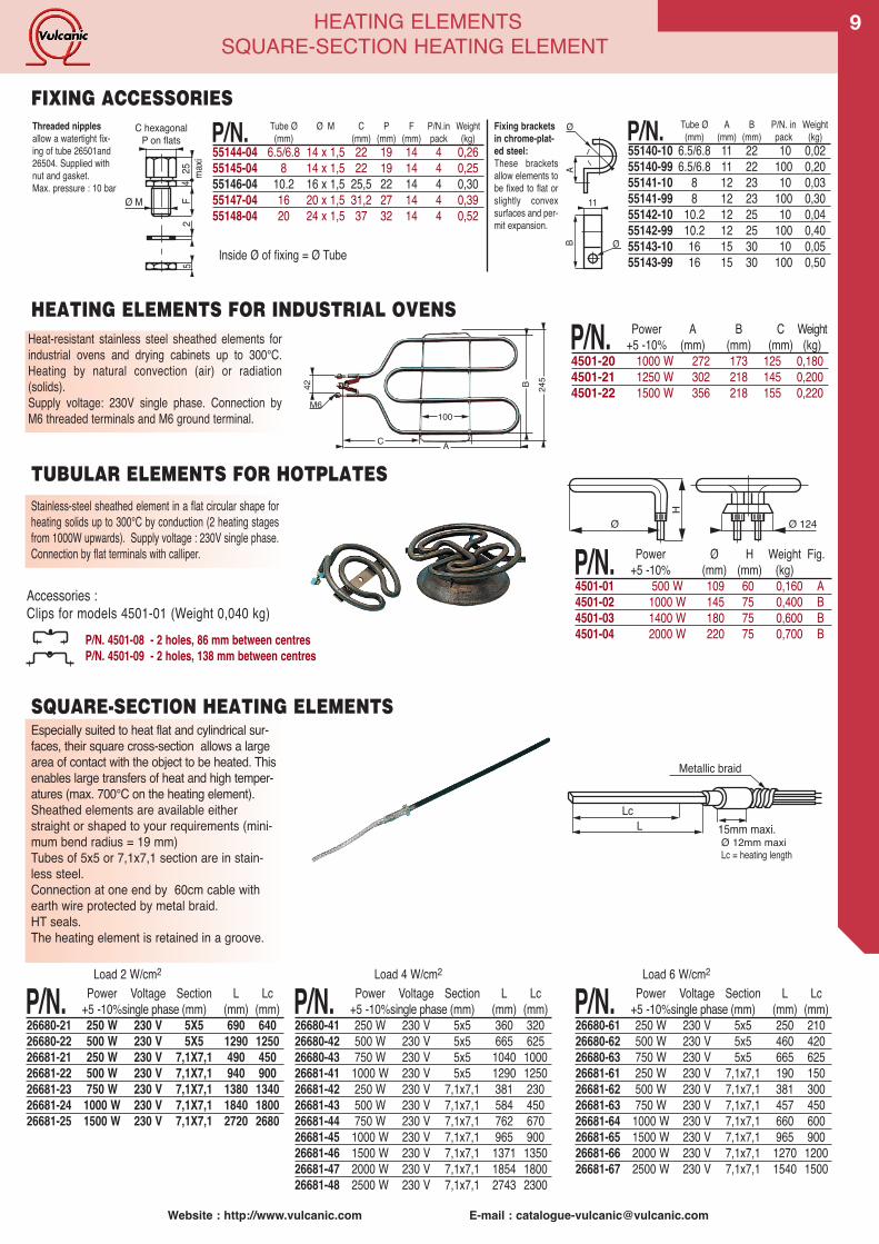
HEATING ELEMENTSSQUARE-SECTION HEATING ELEMENT
Heat-resistant stainless steel sheathed elements forindustrial ovens and drying cabinets up to 300°C.Heating by natural convection (air) or radiation(solids).Supply voltage: 230V single phase. Connection byM6 threaded terminals and M6 ground terminal.
P/N. Power A B C Weight+5 -10% (mm) (mm) (mm) (kg)
4501-20 1000 W 272 173 125 0,1804501-21 1250 W 302 218 145 0,2004501-22 1500 W 356 218 155 0,220
M6
A
100
42 B 245
C
Stainless-steel sheathed element in a flat circular shape forheating solids up to 300°C by conduction (2 heating stagesfrom 1000W upwards). Supply voltage : 230V single phase.Connection by flat terminals with calliper.
Ø Ø 124
H
P/N. Power Ø H Weight Fig.+5 -10% (mm) (mm) (kg)
4501-01 500 W 109 60 0,160 A4501-02 1000 W 145 75 0,400 B4501-03 1400 W 180 75 0,600 B4501-04 2000 W 220 75 0,700 B
TUBULAR ELEMENTS FOR HOTPLATES
Accessories :Clips for models 4501-01 (Weight 0,040 kg)
Especially suited to heat flat and cylindrical sur-faces, their square cross-section allows a largearea of contact with the object to be heated. Thisenables large transfers of heat and high temper-atures (max. 700°C on the heating element).Sheathed elements are available eitherstraight or shaped to your requirements (mini-mum bend radius = 19 mm)Tubes of 5x5 or 7,1x7,1 section are in stain-less steel.Connection at one end by 60cm cable withearth wire protected by metal braid.HT seals.The heating element is retained in a groove.
P/N. Power Voltage Section L Lc+5 -10%single phase (mm) (mm) (mm)
26680-21 250 W 230 V 5X5 690 64026680-22 500 W 230 V 5X5 1290 125026681-21 250 W 230 V 7,1X7,1 490 45026681-22 500 W 230 V 7,1X7,1 940 90026681-23 750 W 230 V 7,1X7,1 1380 134026681-24 1000 W 230 V 7,1X7,1 1840 180026681-25 1500 W 230 V 7,1X7,1 2720 2680
P/N. Power Voltage Section L Lc+5 -10%single phase (mm) (mm) (mm)
26680-41 250 W 230 V 5x5 360 32026680-42 500 W 230 V 5x5 665 62526680-43 750 W 230 V 5x5 1040 100026681-41 1000 W 230 V 5x5 1290 125026681-42 250 W 230 V 7,1x7,1 381 23026681-43 500 W 230 V 7,1x7,1 584 45026681-44 750 W 230 V 7,1x7,1 762 67026681-45 1000 W 230 V 7,1x7,1 965 90026681-46 1500 W 230 V 7,1x7,1 1371 135026681-47 2000 W 230 V 7,1x7,1 1854 180026681-48 2500 W 230 V 7,1x7,1 2743 2300
P/N. Power Voltage Section L Lc+5 -10%single phase (mm) (mm) (mm)
26680-61 250 W 230 V 5x5 250 21026680-62 500 W 230 V 5x5 460 42026680-63 750 W 230 V 5x5 665 62526681-61 250 W 230 V 7,1x7,1 190 15026681-62 500 W 230 V 7,1x7,1 381 30026681-63 750 W 230 V 7,1x7,1 457 45026681-64 1000 W 230 V 7,1x7,1 660 60026681-65 1500 W 230 V 7,1x7,1 965 90026681-66 2000 W 230 V 7,1x7,1 1270 120026681-67 2500 W 230 V 7,1x7,1 1540 1500
LcL
Metallic braid
15mm maxi.
Load 2 W/cm2 Load 4 W/cm2 Load 6 W/cm2
SQUARE-SECTION HEATING ELEMENTS
P/N. 4501-08 - 2 holes, 86 mm between centresP/N. 4501-09 - 2 holes, 138 mm between centres
HEATING ELEMENTS FOR INDUSTRIAL OVENS
Fixing bracketsin chrome-plat-ed steel:These bracketsallow elements tobe fixed to flat orslightly convexsurfaces and per-mit expansion.
P/N. Tube Ø Ø M C P F P/N.in Weight(mm) (mm) (mm) (mm) pack (kg)
55144-04 6.5/6.8 14 x 1,5 22 19 14 4 0,2655145-04 8 14 x 1,5 22 19 14 4 0,2555146-04 10.2 16 x 1,5 25,5 22 14 4 0,3055147-04 16 20 x 1,5 31,2 27 14 4 0,3955148-04 20 24 x 1,5 37 32 14 4 0,52
Ø
A
11
B Ø
C hexagonalP on flats
25 maxi
4F
25
Ø M
FIXING ACCESSORIES
Inside Ø of fixing = Ø Tube
Threaded nipplesallow a watertight fix-ing of tube 26501and26504. Supplied withnut and gasket.Max. pressure : 10 bar
P/N. Tube Ø A B P/N. in Weight(mm) (mm) (mm) pack (kg)
55140-10 6.5/6.8 11 22 10 0,0255140-99 6.5/6.8 11 22 100 0,2055141-10 8 12 23 10 0,0355141-99 8 12 23 100 0,3055142-10 10.2 12 25 10 0,0455142-99 10.2 12 25 100 0,4055143-10 16 15 30 10 0,0555143-99 16 15 30 100 0,50
Ø 12mm maxiLc = heating length
Website : http://www.vulcanic.com E-mail : [email protected]
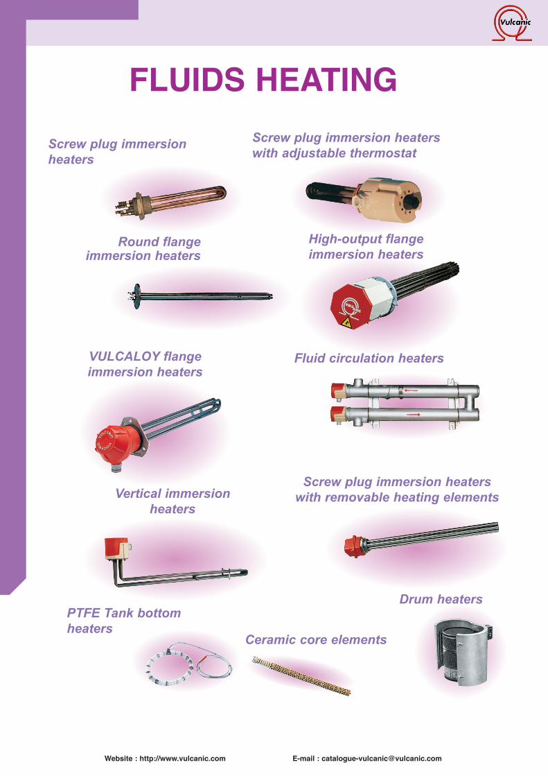
Screw plug immersion heaterswith adjustable thermostat
Round flangeimmersion heaters
VULCALOY flangeimmersion heaters
High-output flangeimmersion heaters
Vertical immersionheaters
Screw plug immersion heaterswith removable heating elements
Ceramic core elements
PTFE Tank bottomheaters
Drum heaters
Screw plug immersionheaters
FLUIDS HEATING
Fluid circulation heaters
Website : http://www.vulcanic.com E-mail : [email protected]
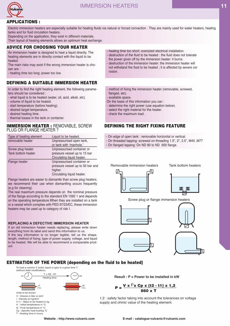
11IMMERSION HEATERS
An immersion heater is designed to heat a liquid directly. Theheating elements are in directly contact with the liquid to beheated.The main risks may exist if the wrong immersion heater is cho-sen are :- heating time too long: power too low.
Electric immersion heaters are especially suitable for heating fluids via natural or forced convection . They are mainly used for water heaters, heatingtanks and for fluid circulation heaters.Depending on the application, they exist in different materials.Their layout of heating elements allows an optimum heat exchange.
To heat a volume V (solid, liquid or gas) in a given time T(without state modification).
V : Volume in liter or dm3Units to be known
r : Density en kg/dm3V x r : Mass to be heated in kgt1 : Initial température in °Ct2 : Final température in °CCp : Specific heat kcal/kg.°CT : Heating time in hours.
1
T = H2 - H1Heating time
V V
H1 H2
t1(°C)
t2(°C)
APPLICATIONS :
ADVICE FOR CHOOSING YOUR HEATER- heating time too short: oversized electrical installation.- destruction of the fluid to be heated : the fluid does not tolerate
the power given off by the immersion heater: it burns.- destruction of the immersion heater: the immersion heater will
not withstand the fluid to be heated ; it is affected by severe corrosion.
Type of heating element Liquid to be heated.removable heater Unpressurised open tank,
or tank with ʻmanhole.ʼScrew plug heater Unpressurised container orTank bottom heater pressure vessel up to 15 bar
Circulating liquid heater.Flange heater Unpressurised container or
pressure vessel up to 50 bar andhigher.Circulating liquid heater.
Flange heaters are easier to dismantle than screw plug heaters;we recommend their use when dismantling occurs frequently(e.g for cleaning).The real maximum pressure depends on the nominal pressureof the flange according to the standard EN 1092 1 and dependson the operating temperature.When they are installed on a tankor a vessel which complies with PED 97/23/EC, these immersionheaters may be used up to category of risk I.
Removable immersion heaters
Screw plug or flange immersion heaters using onfluid circulation heaters
Screw plug or flange immersion heaters
Tank bottom heaters
In order to find the right heating element, the following parame-ters should be considered :- what liquid is to be heated (water, oil, acid, alkali, etc).- volume of liquid to be heated.- start temperature (before heating).- desired target temperature.- desired heating time.- thermal losses in the tank or container.
- method of fixing the immersion heater (removable, screwed,flanged, etc).
- available space.On the basis of this information you can :- determine the right power (use equation below).- select the right material for the heater.- check the maximum load .
IMMERSION HEATER : REMOVABLE, SCREWPLUG OR FLANGE HEATER ?
REPLACING A DEFECTIVE IMMERSION HEATERIf an old immersion heater needs replacing, please write downeverything from its label and send this information to us.If the key information is no longer legible, tell us the shape,length, method of fixing, type of power supply, voltage, and liquidto be heated. We will be able to recommend a comparable prod-uct.
- On edge of open tank : removable horizontal or vertical.- On threaded tapping: screwed on threading 1.5”, 2”, 2.5”, M45 ,M77- On flanged tapping: On ND 80 to ND 600 flange.
DEFINING THE RIGHT FIXING FEATURE
ESTIMATION OF THE POWER (depending on the fluid to be heated)
1,2 : safety factor taking into account the tolerances on voltagesupply and ohmic value of the heating element.
Result : P = Power to be installed in kW
P = V x x Cp x (t2 - t1) x 1,2 860 x T
ρ
DEFINING A SUITABLE IMMERSION HEATER
Website : http://www.vulcanic.com E-mail : [email protected]
12 IMMERSION HEATERS
Brazed
Welde
d
Load
(w/cm
2 )Ste
elGa
lvanis
edste
elNic
kel-pla
tedcop
perSta
inless
steelA
ISI321
Stainle
ssste
elAISI
316L
VLY/A
ISI90
4LPy
rexTe
flon
Incolo
y800
Incolo
y825
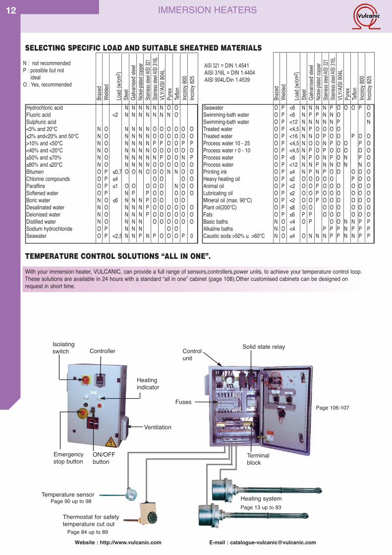
Hydrochloric acid N N N N N N O OFluoric acid <2 N N N N N N N OSulphuric acid<3% and 20°C N O N N N N O O O O O O≤3% and<20% and 50°C N O N N N N O O O O O O>10% and <50°C N O N N N N P P O O P P<40% and <20°C N O N N N N O O O O O O≤50% and ≤70% N O N N N N N P O O N P≤80% and ≤20°C N O N N N N O O O O O OBitumen O P ≤0,7 O O N O O O N N O OChlorine compounds O P ≤4 O O O OParaffins O P ≤1 O O O O O N O OSoftened water O P N P P O O O O OBoric water N O ≤6 N N N P O O O ODesalinated water N O N N N P O O O O O ODeionised water N O N N N P O O O O O ODistilled water N O N N N O O O O O OSodium hydrochloride O P N N N O OSeawater O P <2,5 N N P N P O O O P 0
Seawater O P <6 N N N N P O O O P OSwimming-bath water O P <6 N P P N N O OSwimming-bath water O P <12 N N N N N P NTreated water O P <4,5 N P O O O OTreated water O P <16 N N O P O O P O OProcess water 10 - 25 O P <4,5 N O O N P O O P OProcess water r 0 - 10 O P <4,5 N P O P O O O O OProcess water O P <8 N P O N P O N P OProcess water O P <12 N N P N N O N N OPrinting ink O P ≤4 N P N P O O O O OHeavy heating oil O P ≤2 O O O O O P O OAnimal oil O P <2 O O P O O O O O OLubricating oil O P ≤2 O O P O O O O O OMineral oil (max. 90°C) O P <2 O O P O O O O O OPlant oil(200°C) O P ≤8 O O O O O O O OFats O P ≤6 P P O O O O O OBasic baths N O <4 O P O O N N P PAlkaline baths N O <4 P P P N P P PCaustic soda >50% u. >60°C N O ≤4 O N N N P P N N P P
N : not recommendedP : possible but not
idealO : Yes, recommended
AISI 321 = DIN 1.4541AISI 316L = DIN 1.4404AISI 904L/Din 1.4539
SELECTING SPECIFIC LOAD AND SUITABLE SHEATHED MATERIALS
With your immersion heater, VULCANIC, can provide a full range of sensors,controllers,power units, to achieve your temperature control loop.These solutions are available in 24 hours with a standard “all in one” cabinet (page 108).Other customised cabinets can be designed onrequest in short time.
TEMPERATURE CONTROL SOLUTIONS “ALL IN ONE”.
Brazed
Welded
Load(w/cm
2 )Steel
Galvanisedsteel
Nickel-platedcopper
StainlesssteelAISI321
StainlesssteelAISI316L
VLY/AISI904L
Pyrex
Teflon
Incolo
y800
Incolo
y825
Isolatingswitch Controller
Fuses
Solid state relayControlunit
Emergencystop button
Heatingindicator
ON/OFFbutton
Terminalblock
Ventilation
Temperature sensor
Thermostat for safetytemperature cut out
Heating systemPage 13 up to 83
Page 90 up to 98
Page 84 up to 89
Page 106-107
Website : http://www.vulcanic.com E-mail : [email protected]
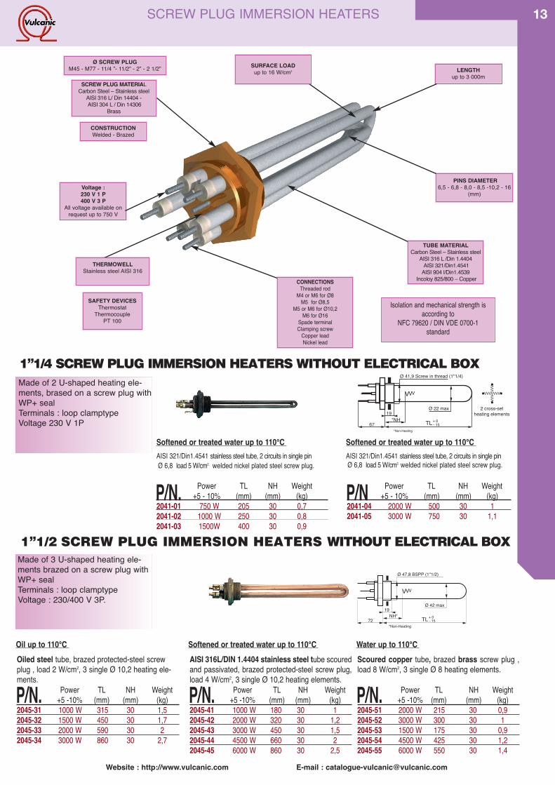
13SCREW PLUG IMMERSION HEATERS
PINS DIAMETER6,5 - 6,8 - 8,0 - 8,5 -10,2 - 16
(mm)
SAFETY DEVICESThermostat
ThermocouplePT 100
CONSTRUCTIONWelded - Brazed
Ø SCREW PLUGM45 - M77 - 11/4 ”- 11/2” - 2” - 2 1/2” SURFACE LOAD
up to 16 W/cm2
TUBE MATERIALCarbon Steel – Stainless steel
AISI 316 L /Din 1.4404AISI 321/Din1.4541
AISI 904 l/Din1.4539Incoloy 825/800 – Copper
LENGTHup to 3 000m
THERMOWELLStainless steel AISI 316
SCREW PLUG MATERIALCarbon Steel – Stainless steel
AISI 316 L/ Din 14404 -AISI 304 L / Din 14306
Brass
Made of 2 U-shaped heating ele-ments, brased on a screw plug withWP+ sealTerminals : loop clamptypeVoltage 230 V 1P
19
VVV
*NH TL67
Ø 41,9 Screw in thread (1''1/4)
Ø 22 max 2 cross-setheating elements
- 15+ 0
VVVVVVV
VVV
VVV
*Non-Heating
1”1/4 SCREWPLUG IMMERSIONHEATERSWITHOUT ELECTRICAL BOX
AISI 321/Din1.4541 stainless steel tube, 2 circuits in single pinØ 6,8 load 5 W/cm2. welded nickel plated steel screw plug.
P/N. Power TL NH Weight+5 - 10% (mm) (mm) (kg)
2041-01 750 W 205 30 0,72041-02 1000 W 250 30 0,82041-03 1500W 400 30 0,9
P/N Power TL NH Weight+5 - 10% (mm) (mm) (kg)
2041-04 2000 W 500 30 12041-05 3000 W 750 30 1,1
Made of 3 U-shaped heating ele-ments brazed on a screw plug withWP+ sealTerminals : loop clamptypeVoltage : 230/400 V 3P.
19
VVV
NH* TL72
Ø 47,8 BSPP (1''1/2)
Ø 42 max
- 15+ 0
*Non-Heating
Scoured copper tube, brazed brass screw plug ,load 8 W/cm2, 3 single Ø 8 heating elements.
P/N. Power TL NH Weight+5 -10% (mm) (mm) (kg)
2045-51 2000 W 215 30 0,92045-52 3000 W 300 30 12045-53 1500 W 175 30 0,92045-54 4500 W 425 30 1,22045-55 6000 W 550 30 1,4
1”1/2 SCREW PLUG IMMERSION HEATERS WITHOUT ELECTRICAL BOX
AISI 316L/DIN 1.4404 stainless steel tube scouredand passivated, brazed protected-steel screw plug,load 4 W/cm2, 3 single Ø 10,2 heating elements.
P/N. Power TL NH Weight+5 -10% (mm) (mm) (kg)
2045-41 1000 W 180 30 12045-42 2000 W 320 30 1,22045-43 3000 W 450 30 1,52045-44 4500 W 660 30 22045-45 6000 W 860 30 2,5
Oiled steel tube, brazed protected-steel screwplug , load 2 W/cm2, 3 single Ø 10,2 heating ele-ments.
P/N. Power TL NH Weight+5 -10% (mm) (mm) (kg)
2045-31 1000 W 315 30 1,52045-32 1500 W 450 30 1,72045-33 2000 W 590 30 22045-34 3000 W 860 30 2,7
Oil up to 110°C Softened or treated water up to 110°C Water up to 110°C
Softened or treated water up to 110°C Softened or treated water up to 110°CAISI 321/Din1.4541 stainless steel tube, 2 circuits in single pinØ 6,8 load 5 W/cm2. welded nickel plated steel screw plug.
Voltage :230 V 1 P400 V 3 P
All voltage available onrequest up to 750 V
CONNECTIONSThreaded rod
M4 or M6 for Ø8M5 for Ø8,5
M5 or M6 for Ø10,2M6 for Ø16
Spade terminalClamping screw
Copper leadNickel lead
Isolation and mechanical strength isaccording to
NFC 79620 / DIN VDE 0700-1standard

Website : http://www.vulcanic.com E-mail : [email protected]
14 1”1/2 SCREW PLUGIMMERSION HEATERS
1”1/2 SCREW PLUG IMMERSION HEATERS WITHOUT ELECTRICAL BOXMade of U-shaped heating elements soldered on ascrew plug with waterproof sealing.Threaded terminals : M 4.Pins diameter : 8 mm.
Type CEM AISI 316L / Din1.4404 stainless steeltube, welded stainless steel screw plug.
P/N. Power voltage Load TL NH Weight+5 -10% (V) (W/cm2) (mm) (mm) (kg)
2114-22 *750 W 230 1P 4 230 40 0,72114-23 3000 W 230 1P 10 230 40 0,72114-24 4500 W 230/400 11 330 40 0,92114-25 6000 W 230/400 11 430 40 1,12114-26 7500 W 230/400 10 600 40 1,32114-27 9000 W 230/400 9 750 40 1,5
Type CEC AISI 321 / Din1.4541 stainless steeltube, brazed brass screw plug.
P/N. Power voltage Load TL NH Weight+5 -10% (V) (W/cm2) (mm) (mm) (kg)
2114-10 2000 W 230 1P 10 170 40 0,62114-11 3000 W 230 1P 10 230 40 0,72114-12 4500 W 230/400 10 330 40 0,92114-13 6000 W 230/400 10 430 40 1,12114-14 7500 W 230/400 9 600 40 1,32114-15 9000 W 230/400 9 750 40 1,5
Type CES AISI 321 / Din1.4541 stainless steeltube, welded steel screw plug.
P/N. Power voltage Load TL NH Weight+5 -10% (V) (W/cm2) (mm) (mm) (kg)
2114-01 1000 W 230 1P 2 370 40 0,82114-02 1500 W 230 1P 2 540 40 1,22114-03 2000 W 230 1P 2 700 40 1,32114-04 3000 W 230 1P 2 1040 40 1,6
Non moving oil up to 95°C Circuit water up to 95°C Aggressive fluid* or deionized water up to 95°C
Type CEMI Incoloy 825 / Din2.4858 stainless steeltube, welded stainless steel screw plug..
P/N. Power voltage Load TL NH Weight+5 -10% (V) (W/cm2) (mm) (mm) (kg)
2114-28 3000 W 230 1P 6 380 40 1,02114-29 4500 W 230 1P 7 470 40 1,22114-30 6000 W 230/400 10 470 40 1,22114-31 7500 W 230/400 10 600 40 1,32114-32 9000 W 230/400 10 690 40 1,35
Type CEI Incoloy 825 / Din2.4858 stainless steeltube, brazed brass screw plug.
P/N. Power voltage Load TL NH Weight+5 -10% (V) (W/cm2) (mm) (mm) (kg)
2114-16 2000 W 230 1P 6 470 100 1,22114-17 3000 W 230 1P 7 380 100 1,02114-18 4500 W 230/400 8 470 100 1,22114-19 6000 W 230/400 11 470 100 1,22114-20 7500 W 230/400 10 600 100 1,32114-21 9000 W 230/400 10 690 100 1,35
Type CEs AISI 321 / Din1.4541 stainless steeltube, brazed brass screw plug..
P/N. Power voltage Load TL NH Weight+5 -10% (V) (W/cm2)(mm) (mm) (kg)
2114-06 2000 W 230 1P 5 300 40 0,82114-07 3000 W 230 1P 5 480 40 1,22114-08 4500 W 230/400 5 670 40 1,32114-09 6000 W 230/400 5 960 40 1,8
Flowing oil 2 m/s up to 95°C Domestic water up to 95°C Liquids with chloride content up to 95°C(e.g salt water)
1”1/2 SCREW PLUG IMMERSION HEATERS WITH ELECTRICAL BOXMade of U-shaped heating elements soldered on ascrew plug with waterproof sealing.Electrical box in polyamide.Screwed cable gland.Pins diameter : 8 mm.Protection class IP 54.
VVVVVVVVVVVV
40
NH*TL60 8 +- 20
Ø85
thermowell
15 Ø 47,8 1"1/2 BSPPGlands ISO 20bis
*Non-Heating length
Circuit water up to 95°CFlowing oil 2 m/s up to 95°C
Type CRI Incoloy 825 / Din2.4858 stainless steeltube , special welded insulation inside a brassscrew plug.
P/N. Power voltage Load TL NH Weight+5 -10% (V) (W/cm2) (mm) (mm) (kg)
2115-35 2000 W 230 1P 6 470 100 2,02115-36 3000 W 230 1P 7 380 100 1,72115-37 4500 W 230/400 8 470 100 2,02115-38 6000 W 230/400 11 470 100 2,02115-39 7500 W 230/400 10 600 100 2,12115-40 9000 W 230/400 10 690 100 2,2
Circuit water up to 95°C for enamelled tank
Type CES AISI 321 / Din1.4541 stainless steeltube, welded steel screw plug.
P/N. Power voltage Load TL NH Weight+5 -10% (V) (W/cm2) (mm) (mm) (kg)
2115-01 1000 W 230 1P 2 370 40 1,52115-02 1500 W 230 1P 2 540 40 2,02115-03 2000 W 230 1P 2 700 40 2,22115-04 3000 W 230 1P 2 1040 40 2,4
Non moving oil up to 95°C
Type CES AISI 321 / Din1.4541 stainless steeltube, welded steel screw plug.
P/N. Power voltage Load TL NH Weight+5 -10% (V) (W/cm2)(mm) (mm) (kg)
2115-06 2000 W 230 1P 5 300 40 1,52115-07 3000 W 230 1P 5 480 40 22115-08 4500 W 230/400 5 670 40 2,22115-09 6000 W 230/400 5 960 40 2,5
Type CEC AISI 321 / Din1.4541 stainless steeltube, brazed brass screw plug.
P/N. Power voltage Load TL NH Weight+5 -10% (V) (W/cm2) (mm) (mm) (kg)
2115-10 2000 W 230 1P 10 170 40 1,22115-11 3000 W 230 1P 10 230 40 1,42115-12 4500 W 230/400 10 330 40 1,62115-13 6000 W 230/400 10 430 40 1,72115-14 7500 W 230/400 9 600 40 2,12115-15 9000 W 230/400 9 750 40 2,3
G 1"1/2
158
NH Thermowell
40
TL

151”1/2 SCREW PLUGIMMERSION HEATERS
Type CEM AISI 316L / Din1.4404 stainless steeltube , welded stainless steel screw plug.
P/N. Power voltage Load TL NH Weight+5 -10% (V) (W/cm2) (mm) (mm) (kg)
2115-22 *750 W 230 1P 4 230 40 1,42115-23 3000 W 230 1P 10 230 40 1,42115-24 4500 W 230/400 11 330 40 1,62115-25 6000 W 230/400 11 430 40 1,82115-26 7500 W 230/400 10 600 40 2,12115-27 9000 W 230/400 9 750 40 2,3
Aggressive fluid* or deionized water up to 95°C
Type CEMI Incoloy 825 / Din2.4858 stainless steeltube , welded stainless steel screw plug..
P/N. Power voltage Load TL NH Weight+5 -10% (V) (W/cm2) (mm) (mm) (kg)
2115-28 3000 W 230 1P 6 380 40 1,72115-29 4500 W 230 1P 7 470 40 2,02115-30 6000 W 230/400 10 470 40 2,02115-31 7500 W 230/400 10 600 40 2,12115-32 9000 W 230/400 10 690 40 2,2
Domestic water up to 95°C Liquids with chloride content up to 95°C(e.g salt water)
1”1/2 SCREW PLUG IMMERSION HEATERS WITH ELECTRICAL BOX
AND ADJUSTABLE THERMOSTATMade of U-shaped heating elements solderedon a screw plug with waterproof sealingElectrical box in polyamideScrewed cable glandPins diameter : 8 mmProtection class IP 44, external offset X=6Protection class IP 54, internal offset X=7Built-in single-pole temperature thermostatfrom 0 up to 100°C, 16A/250V 1P
VVVVVVVVVVVV
40*NH
TL120 8 +- 20
Ø85
Thermowell
15 Ø 47,8 1"1/2 BSPPGlands ISO 20bis
*Non-Heating length
Type CEI Incoloy 825 / Din2.4858 stainless steeltube , brazed brass screw plug.
P/N. Power voltage Load TL NH Weight+5 -10% (V) (W/cm2) (mm) (mm) (kg)
2115-16 2000 W 230 1P 6 470 100 2,02115-17 3000 W 230 1P 7 380 100 1,72115-18 4500 W 230/400 8 470 100 2,02115-19 6000 W 230/400 11 470 100 2,02115-20 7500 W 230/400 10 600 100 2,12115-21 9000 W 230/400 10 690 100 2,2
Type CEM AISI 316L / Din1.4404 stainless steeltube, welded stainless steel screw plug.
P/N. Power voltage Load TL NH Weight+5 -10% (V) (W/cm2) (mm) (mm) (kg)
211X-22 750 W 230 1P 4 230 40 1,1211X-23 3000 W 230 1P 10 230 40 1,1211X-24 4500 W 400 3P 11 330 40 1,2211X-25 6000 W 400 3P 11 430 40 1,4211X-26 7500 W 400 3P 10 600 40 1,7211X-27 9000 W 400 3P 9 750 40 1,9
Type CEC AISI 321 / Din1.4541 stainless steeltube, brazed brass screw plug.
P/N. Power voltage Load TL NH Weight+5 -10% (V) (W/cm2) (mm) (mm) (kg)
211X-10 2000 W 230 1P 10 170 40 1,0211X-11 3000 W 230 1P 10 230 40 1,1211X-12 4500 W 400 3P 10 330 40 1,2211X-13 6000 W 400 3P 10 430 40 1,4211X-14 7500 W 400 3P 9 600 40 1,7211X-15 9000 W 400 3P 9 750 40 1,9
Type CES AISI 321 / Din1.4541 stainless steeltube, welded steel screw plug.
P/N. Power voltage Load TL NH Weight+5 -10% (V) (W/cm2) (mm) (mm) (kg)
211X-01 1000 W 230 1P 2 370 40 1,2211X-02 1500 W 230 1P 2 540 40 1,5211X-03 2000 W 230 1P 2 700 40 1,7211X-04 3000 W 230 1P 2 1040 40 2,1
Non moving oil up to 95°C Circuit water up to 95°C Aggressive-fluid and deionized water up to 95°C
Type CEMI Incoloy 825 / Din2.4858 stainless steeltube ,welded stainless steel screw plug.
P/N. Power voltage Load TL NH Weight+5 -10% (V) (W/cm2) (mm) (mm) (kg)
211X-28 3000 W 230 1P 6 380 40 1,3211X-29 4500 W 230 1P 7 470 40 1,5211X-30 6000 W 400 3P 10 470 40 1,5211X-31 7500 W 400 3P 10 600 40 1,7211X-32 9000 W 400 3P 10 690 40 1,8
Type CEI Incoloy 825 / Din2.4858 stainless steeltube, brazed brass screw plug.
P/N. Power voltage Load TL NH Weight+5 -10% (V) (W/cm2) (mm) (mm) (kg)
211X-16 2000 W 230 1P 6 470 100 1,5211X-17 3000 W 230 1P 7 380 100 1,3211X-18 4500 W 400 3P 8 470 100 1,5211X-19 6000 W 400 3P 11 470 100 1,5211X-20 7500 W 400 3P 10 600 100 1,7211X-21 9000 W 400 3P 10 690 100 1,8
Type CES AISI 321 / Din1.4541 stainless steeltube, welded steel screw plug.
P/N. Power voltage Load TL NH Weight+5 -10% (V) (W/cm2)(mm) (mm) (kg)
211X-06 2000 W 230 1P 5 300 40 1,2211X-07 3000 W 230 1P 5 480 40 1,5211X-08 4500 W 400 3P 5 670 40 1,8211X-09 6000 W 400 3P 5 960 40 2,2
Flowing oil 2 m/s up to 95°C Domestic water up to 95°C Liquids with chloride content up to 95°C(e.g salt water)
Website : http://www.vulcanic.com E-mail : [email protected]
Type CRI Incoloy 825 / Din2.4858 stainless steeltube , special welded isolation inside a brassscrew plug.
P/N. Power voltage Load TL NH Weight+5 -10% (V) (W/cm2) (mm) (mm) (kg)
211X-35 2000 W 230 1P 6 470 100 1,6211X-36 3000 W 230 1P 7 380 100 1,4211X-37 4500 W 400 3P 8 470 100 1,6211X-38 6000 W 400 3P 11 470 100 1,6211X-39 7500 W 400 3P 10 600 100 1,8211X-40 9000 W 400 3P 10 690 100 1,9
Circuit water up to 95°C for enamelled tank

Website : http://www.vulcanic.com E-mail : [email protected]
16 1”1/2 SCREW PLUGIMMERSION HEATERS
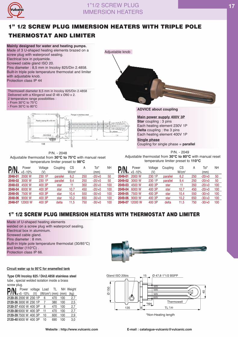
1”1/2 SCREW PLUG IMMERSION HEATERS WITH TRIPLE POLE
THERMOSTAT AND LIMITER.Made of U-shaped heating elements soldered on ascrew plug with waterproof sealing.Electrical box in polyamide.Screwed cable gland.Pins diameter : 8 mm.Built-in triple-pole temperature thermostat ( 30-85°C)and limiter (110°C).Protection class IP 44(a) external offset X=8Protection class IP 54 (i) internal offset X=9
VVVVVVVVVVVV
40
NH*TL142 8 +- 20
Ø11
6
Thermowell
15 Ø 47,8 1"1/2 BSPPGland ISO 20 bis
*Non-Heating length
Type CEM AISI 316L / Din1.4404 stainless steeltube, welded stainless steel screw plug.
P/N. Power voltage Load TL NH Weight+5 -10% (V) (W/cm2) (mm) (mm) (kg)
211X-22 750 W 230 1P 4 230 40 1,3211X-23 3000 W 230 1P 10 230 40 1,3211X-24 4500 W 400 3P 11 330 40 1,4211X-25 6000 W 400 3P 11 430 40 1,7211X-26 7500 W 400 3P 10 600 40 1,9211X-27 9000 W 400 3P 9 750 40 2,3
Type CEC AISI 321 / Din1.4541 stainless steeltube, brazed brass screw plug.
P/N. Power voltage Load TL NH Weight+5 -10% (V) (W/cm2) (mm) (mm) (kg)
211X-10 2000 W 230 1P 10 170 40 1,2211X-11 3000 W 230 1P 10 230 40 1,3211X-12 4500 W 400 3P 10 330 40 1,4211X-13 6000 W 400 3P 10 430 40 1,7211X-14 7500 W 400 3P 9 600 40 1,9211X-15 9000 W 400 3P 9 750 40 2,3
Type CES AISI 321 / Din1.4541 stainless steeltube, welded steel screw plug.
P/N. Power voltage Load TL NH Weight+5 -10% (V) (W/cm2) (mm) (mm) (kg)
211X-01 1000 W 230 1P 2 370 40 1,5211X-02 1500 W 230 1P 2 540 40 1,7211X-03 2000 W 230 1P 2 700 40 1,9211X-04 3000 W 230 1P 2 1040 40 2,4
Non moving oil up to 85°C Circuit water up to 85°C Aggressive-fluid* or deionized water up to 85°C
Type CEMI Incoloy 825 / Din2.4858 stainless steeltube ,welded stainless steel screw plug.
P/N. Power voltage Load TL NH Weight+5 -10% (V) (W/cm2) (mm) (mm) (kg)
211X-28 3000 W 230 1P 6 380 40 1,5211X-29 4500 W 230 1P 7 470 40 1,7211X-30 6000 W 400 3P 10 470 40 1,7211X-31 7500 W 400 3P 10 600 40 1,9211X-32 9000 W 400 3P 10 690 40 2,1
Type CEI Incoloy 825 / Din2.4858 stainless steeltube, brazed brass screw plug.
P/N. Power voltage Load TL NH Weight+5 -10% (V) (W/cm2) (mm) (mm) (kg)
211X-16 2000 W 230 1P 6 470 100 1,7211X-17 3000 W 230 1P 7 380 100 1,5211X-18 4500 W 400 3P 8 470 100 1,7211X-19 6000 W 400 3P 11 470 100 1,7211X-20 7500 W 400 3P 10 600 100 1,9211X-21 9000 W 400 3P 10 690 100 2,1
Type CES AISI 321 / Din1.4541 stainless steeltube, welded steel screw plug.
P/N. Power voltage Load TL NH Weight+5 -10% (V) (W/cm2)(mm) (mm) (kg)
211X-06 2000 W 230 1P 5 300 40 1,5211X-07 3000 W 230 1P 5 480 40 1,7211X-08 4500 W 400 3P 5 670 40 2,1211X-09 6000 W 400 3P 5 960 40 2,5
Flowing oil 2 m/s up to 85°C Domestic water up to 85°C Liquids with chloride content up to 85°C(e.g salt water)
Type CRI Incoloy 825 / Din2.4858 stainless steeltube , special welded isolation inside a brassscrew plug.
P/N. Power voltage Load TL NH Weight+5 -10% (V) (W/cm2) (mm) (mm) (kg)
211X-35 2000 W 230 1P 6 470 100 1,8211X-36 3000 W 230 1P 7 380 100 1,6211X-37 4500 W 400 3P 8 470 100 1,8211X-38 6000 W 400 3P 11 470 100 1,8211X-39 7500 W 400 3P 10 600 100 2,0211X-40 9000 W 400 3P 10 690 100 2,2
Circuit water up to 85°C for enamelled tank
Website : http://www.vulcanic.com E-mail : [email protected]
17
Made of U-shaped heating elementswelded on a screw plug with waterproof sealing.Electrical box in aluminium.Screwed cable gland.Pins diameter : 8 mm.Built-in triple pole temperature thermostat (30/85°C)and limiter (110°C) .Protection class IP 66.
VVVVVVVVVVVV
40
*NHTL135 8 +- 20
Ø15
0
Thermowell
15 Ø 47,8 1"1/2 BSPPGland ISO 20bis
*Non-Heating length
1” 1/2 SCREW PLUG IMMERSION HEATERS WITH THERMOSTAT AND LIMITER
Type CRI Incoloy 825 / Din2.4858 stainless steeltube , special welded isolation inside a brassscrew plug.
P/N. Power voltage Load TL NH Weight+5 -10% (V) (W/cm2) (mm) (mm) (kg)
2120-35 2000 W 230 1P 6 470 100 2,72120-36 3000 W 230 1P 7 380 100 2,52120-37 4500 W 400 3P 8 470 100 2,72120-38 6000 W 400 3P 11 470 100 2,72120-39 7500 W 400 3P 10 600 100 2,92120-40 9000 W 400 3P 10 690 100 3,0
Circuit water up to 95°C for enamelled tank
P/N. Power Voltage Coupling CS A Tol* NH+5 -10% (V) W/cm2 (mm)
2048-01 2000 W 230 1P parallel 6,2 250 -20/+0 502048-02 3000 W 230 1P parallel 9,4 250 -20/+0 502048-03 4500 W 400 3P star 11 350 -20/+0 1002048-04 6000 W 400 3P star 10,7 450 -20/+0 1002048-05 7500 W 400 3P star 10,4 550 -30/+0 1002048-06 9000 W 400 3P star 10,2 650 -30/+0 1002048-07 12000 W 400 3P delta 11,5 750 -30/+0 100
P/N. Power Voltage Coupling CS A Tol* NH+5 -10% (V) W/cm2 (mm)
2049-01 2000 W 230 1P parallel 6,2 250 -20/+0 502049-02 3000 W 230 1P parallel 9,4 250 -20/+0 502049-03 4500 W 400 3P star 11 350 -20/+0 1002049-04 6000 W 400 3P star 10,7 450 -20/+0 1002049-05 7500 W 400 3P star 10,4 550 -30/+0 1002049-06 9000 W 400 3P star 10,2 650 -30/+0 1002049-07 12000 W 400 3P delta 11,5 750 -30/+0 100
P/N. - 2048Adjustable thermostat from 30°C to 75°C with manual reset
temperature limiter preset to 98°C
P/N. - 2049Adjustable thermostat from 30°C to 80°C with manual reset
temperature limiter preset to 110°C
ADVICE about coupling
Main power supply 400V 3PStar coupling : 3 pinsEach heating element 230V 1PDelta coupling : the 3 pinsEach heating element 400V 1PSingle phaseCoupling for single phase = parallel
Plastic casing 90 x 90 mm
Flange in stainless steel
BSPP
1"1/2
A
Gland ISO 20
Ø < 42mm
108
1” 1/2 SCREW PLUG IMMERSION HEATERS WITH TRIPLE POLE
THERMOSTAT AND LIMITER
1”1/2 SCREW PLUGIMMERSION HEATERS
Adjustable knobMainly designed for water and heating pumps.Made of 3 U-shaped heating elements brazed on ascrew plug with waterproof sealing.Electrical box in polyamide.Screwed cable gland ISO 20.Pins diameter : 8,5 mm in Incoloy 825/Din 2.4858.Built-in triple pole temperature thermostat and limiterwith adjustable knob.Protection class IP 44
Thermowell diameter 8,5 mm in Incoloy 825/Din 2.4858Delivered with a Klingersil seal Ø 48 x Ø60 x 2.2 temperature range possibilities :- From 30°C to 75°C- From 30°C to 80°C

Website : http://www.vulcanic.com E-mail : [email protected]
18 1”1/2 SCREW PLUGIMMERSION HEATERS
Made of U-shaped heating elementssoldered on a screw plug with waterproofsealing.Electrical box in aluminium.Pins diameter : 8 mm.Built-in-triple-poles temperature thermostat(30/85°C) and limiter (110°C) .Protection class IP 66.
1” 1/2 SCREW PLUG IMMERSION HEATERS WITH THERMOSTAT AND LIMITER
Type CEM AISI 316L / Din1.4404 stainless steeltube, welded stainless steel screw plug.
P/N. Power voltage Load TL NH Weight+5 -10% (V) (W/cm2) (mm) (mm) (kg)
2120-22 750 W 230 1P 4 230 40 2,22120-23 3000 W 230 1P 10 230 40 2,22120-24 4500 W 400 3P 11 330 40 2,42120-25 6000 W 400 3P 11 430 40 2,52120-26 7500 W 400 3P 10 600 40 2,72120-27 9000 W 400 3P 9 750 40 3,0
Type CEC AISI 321 / Din1.4541 stainless steeltube, brazed brass screw plug.
P/N. Power voltage Load TL NH Weight+5 -10% (V) (W/cm2) (mm) (mm) (kg)
2120-10 2000 W 230 1P 10 170 40 2,12120-11 3000 W 230 1P 10 230 40 2,22120-12 4500 W 400 3P 10 330 40 2,42120-13 6000 W 400 3P 10 430 40 2,52120-14 7500 W 400 3P 9 600 40 2,72120-15 9000 W 400 3P 9 750 40 3,0
Type CES AISI 321 / Din1.4541 stainless steeltube, welded steel screw plug.
P/N. Power voltage Load TL NH Weight+5 -10% (V) (W/cm2) (mm) (mm) (kg)
2120-01 1000 W 230 1P 2 370 40 2,32120-02 1500 W 230 1P 2 540 40 2,62120-03 2000 W 230 1P 2 700 40 2,72120-04 3000 W 230 1P 2 1040 40 3,2
Non moving oil up to 85°C Circuit water up to 85°C Aggressive-fluid *or deionized water up to 85°C
Type CEMI Incoloy 825 / Din2.4858 stainless steeltube ,welded stainless steel screw plug.
P/N. Power voltage Load TL NH Weight+5 -10% (V) (W/cm2) (mm) (mm) (kg)
2120-28 3000 W 230 1P 6 380 40 2,42120-29 4500 W 230 1P 7 470 40 2,62120-30 6000 W 400 3P 10 470 40 2,62120-31 7500 W 400 3P 10 600 40 2,72120-32 9000 W 400 3P 10 690 40 2,9
Type CEI Incoloy 825 / Din2.4858 stainless steeltube, brazed brass screw plug.
P/N. Power voltage Load TL NH Weight+5 -10% (V) (W/cm2) (mm) (mm) (kg)
2120-16 2000 W 230 1P 6 470 100 2,62120-17 3000 W 230 1P 7 380 100 2,42120-18 4500 W 400 3P 8 470 100 2,62120-19 6000 W 400 3P 11 470 100 2,62120-20 7500 W 400 3P 10 600 100 2,72120-21 9000 W 400 3P 10 690 100 2,9
Type CES AISI 321 / Din1.4541 stainless steeltube, welded steel screw plug.
P/N. Power voltage Load TL NH Weight+5 -10% (V) (W/cm2)(mm) (mm) (kg)
2120-06 2000 W 230 1P 5 300 40 2,32120-07 3000 W 230 1P 5 480 40 2,62120-08 4500 W 400 3P 5 670 40 2,82120-09 6000 W 400 3P 5 960 40 3,5
Flowing oil 2 m/s up to 85°C Domestic water up to 85°C Liquids with chloride content up to 85°C(e.g salt water)
VVVVVVVVVVVV
40
*NHTL135 8 +- 20
Ø15
0
Thermowell
15 Ø 47,8 1"1/2 BSPPGland ISO 20bis
*Non-Heating length
Consists of three elements in ring or crossarrangement on a cylindrical screw plug ,with a sealing ring.M6 threaded terminals - WP+ seals.
19
VVV
NcA94
Ø 75,1 Gaz Cyl. (2"1/2)
Ø 70 maxi
- 15+ 0
Nickel-plated copper tube, brazed nickel-plated brassscrew plug, load 8 W/cm2, voltage 230/400 V threephases,(except P/N 207-76, 400V 3P), 3 single ele-ments Ø 16 - Fig. B.
P/N. Puiss. A Nc Masse+5 -10% (mm) (mm) (kg)
Without offset2077-71 6000 W 295 50 2,32077-72 9000 W 420 50 32077-73 12000 W 545 50 3,62077-74 18000 W 850 50 52077-75 24000 W 1100 50 62077-76 36000 W 1620 50 9
2”1/2 BRAZED SCREW PLUG IMMERSION HEATER WITHOUT ELECTRICAL BOX
AISI 316 L/ Din 1.4404 stainless steel tube,scoured andpassivated, welded protected steel screw plug, load5 W/cm2,voltage 230/400 V three phases, 3 single ele-ments.Ø 16 - Fig. B.
P/N. Puiss. A Nc Masse+5 -10% (mm) (mm) (kg)
Without-offset2077-51 3000 W 250 50 2,12077-52 4500 W 360 50 2,72077-53 6000 W 460 50 3,22077-54 9000 W 670 50 4,32077-55 12000 W 870 50 5,3
3 cross set circuits
Fig B
Softened or treated water up to 110°C Water up to 110°C NC=Non heating length

Website : http://www.vulcanic.com E-mail : [email protected]
19SCREW PLUG IMMERSION HEATERSACCESSORIES
RESIN FOR TOTAL SEALING OF TERMINAL BOXESCompletely immerse an immersion heater ? Itʼs perfectlypossible. Just fill the terminal box with this resin, oncethe connections are made. Easy to use , the two-partresin comes in a sealed pack. Break the central partition,mix the contents for a few moments, and the resin isready for use. Caution : do not use on an immersionheater with an integral controller or a control box. If thesupply cable is PTFE covered, wrap it first with elas-tomer ribbon to ensure a perfect seal.
P/N. Description Volume or Weightlength (g)
56073-11 Resin 93ml 10056073-12 Resin 200ml 43056073-21 Elastomer ribbon 9,15m x 19mm 110
These control units are designed to simplify instal-lation of 2” and 2”1/2 immersion heaters withthermowell. Heating is switched on / off by an inte-grated thermostat.Comprises a sealed aluminium IP 55 IK 5 box fittedwith a thermostat and/or a temperature limiter.The solution for small and medium-sized installa-tions.Box 160 x 160, height 135.
160
160135
P/N. Max. power/ nbr of Temp. Thermostat Limiter Resetvoltage contacts range
9027-51 13 kW/400 V 3 P 3 15/80°C 9014-13 110°C manual9027-52 8 kW/400 V 3 P 2 0/300°C 9014-039027-53 8 kW/400 V 3 P 2 0/100°C 9014-049027-54 8 kW/400 V 3 P 2 50/200°C 9014-059027-55 2 kW/230 V 1 P 1 110/550°C 9030-079027-61 3 kW/230 V 1 P 1 90/110°C 9030-31 manual9027-62 5 kW/400 V 3 P 1 50/300°C 9030-05 manual9027-63 5 kW/400 V 3 P 1 20/500°C 9030-06 manual
CONTROL UNITS FOR SCREW IMMERSION HEATERS
SPARE THERMOSTATS
ACCESSORIES AND SEALING RINGS
P/N. Connection52073-01 1”1/2 connection Seal52074-01 2” connection Seal52075-01 1”1/2 connection brass screw plug52076-01 1”1/2 connection stainless steel screw plug52079-01 1”1/2 connection welded sleeve AISI 304/DIN 1.430152080-01 1”1/2 connection welded sleeve AISI 316 Ti/DIN 1.457152081-01 1 1/2 ” connection welded sleeve steel52077-01 Reduction sleeve 2” to 1”1/2 thread52078-01 Reduction sleeve 2” threading to 1”1/2 tapping52082-01 Box spanner 1”1/2 (SW 60 wrench)
P/N. Connection51931-20 Pack of 20 klingersil copper sealing rings for 1” 1/4(0,2 kg)51935-20 Pack of 20 klingersil copper sealing rings for 1” 1/2 (0,2 kg)51937-20 Pack of 20 klingersil sealing rings for 2” (0,34 kg)51939-20 Pack of 20 klingersil sealing rings for 2” 1/2 (0,34 kg)
P/N. Thermostat Temp. Hysteresis/ Limiter Resetrange differential gap
9002-01 Single-pole temperature thermostat 0 /100°C 2,5%9002-02 Single-pole temperature thermostat 50/300°C 10°C9002-03 Single-pole temperature limiter, 10°C 50/300°C manual9003-01 Triple-poles temperature limiter 10°C 80°C automatic9003-02 Triple-poles temperature limiter 10°C 95°C automatic9003-03 Triple-poles temperature limiter 10°C 110°C automatic9003-04 Temperature control and limiter unit TRB3, triple pole temperature control unit, adjustment range :
30...85°C, differential gap : 8°C, triple pole temperature limiter,cut-off temperature : 110°C, manual resetbreaking capacity : 3 x 20A, 400V.
9003-05 Temperature control unit (0...100°C) with sequential contact (+10°C, can also be implemented as a temperature monitor), manual reset
Website : http://www.vulcanic.com E-mail : [email protected]
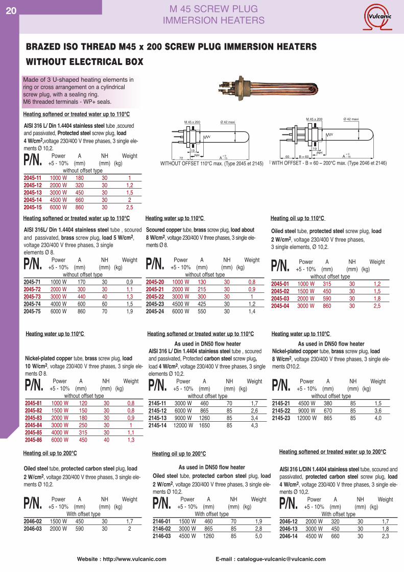
20 M 45 SCREW PLUGIMMERSION HEATERS
Oiled steel tube, protected steel screw plug, load2 W/cm2, voltage 230/400 V three phases,3 single elements, Ø 10,2.
P/N. Power A NH Weight+5 - 10% (mm) (mm) (kg)
without offset type2045-01 1000 W 315 30 1,22045-02 1500 W 450 30 1,52045-03 2000 W 590 30 1,82045-04 3000 W 860 30 2,5
AISI 316 L/ Din 1.4404 stainless steel tube ,scouredand passivated, Protected steel screw plug, load4 W/cm2,voltage 230/400 V three phases, 3 single ele-ments Ø 10,2.
P/N. Power A NH Weight+5 - 10% (mm) (mm) (kg)
without offset type2045-11 1000 W 180 30 12045-12 2000 W 320 30 1,22045-13 3000 W 450 30 1,52045-14 4500 W 660 30 22045-15 6000 W 860 30 2,5
Scoured copper tube, brass screw plug, load about8 W/cm2, voltage 230/400 V three phases, 3 single ele-ments Ø 8.
P/N. Power A NH Weight+5 - 10% (mm) (mm) (kg)
without offset type2045-20 1000 W 130 30 0,82045-21 2000 W 215 30 0,92045-22 3000 W 300 30 12045-23 4500 W 425 30 1,22045-24 6000 W 550 30 1,4
19
VVV
NcA72
M 45 x 200 Ø 42 maxi
NON DEPORTE 110°C maxi (Type 2045 et 2145)- 15+ 0
19
VVV
NcAB = 6060
M 45 x 200 Ø 42 maxi
DEPORTE - B = 60 - 200°C maxi (Type 2046 et 2146)- 15+ 0
Oiled steel tube, protected carbon steel plug, load2 W/cm2, voltage 230/400 V three phases, 3 single ele-ments Ø 10,2.
P/N. Power A NH Weight+5 - 10% (mm) (mm) (kg)
With offset type2046-02 1500 W 450 30 1,72046-03 2000 W 590 30 2
As used in DN50 flow heaterOiled steel tube, protected carbon steel plug, load2 W/cm2, voltage 230/400 V three phases, 3 single ele-ments Ø 10,2.
P/N. Power A NH Weight+5 - 10% (mm) (mm) (kg)
With offset type2146-01 1500 W 460 70 1,92146-02 3000 W 865 85 2,82146-03 4500 W 1260 85 5,0
AISI 316 L/DIN 1.4404 stainless steel tube, scoured andpassivated, protected carbon steel screw plug, load4 W/cm2, voltage 230/400 V three phases, 3 single ele-ments Ø 10,2.
P/N. Power A NH Weight+5 - 10% (mm) (mm) (kg)
With offset type2046-12 2000 W 320 30 1,72046-13 3000 W 450 30 1,82046-14 4500 W 660 30 2,3
As used in DN50 flow heaterAISI 316 L/ Din 1.4404 stainless steel tube , scouredand passivated, Protected carbon steel screw plug,load 4 W/cm2, voltage 230/400 V three phases, 3 singleelements Ø 10,2.
P/N. Power A NH Weight+5 - 10% (mm) (mm) (kg)
without offset type2145-11 3000 W 460 70 1,72145-12 6000 W 865 85 2,62145-13 9000 W 1260 85 3,42145-14 12000 W 1650 85 4,3
As used in DN50 flow heaterNickel-plated copper tube, brass screw plug, load8 W/cm2, voltage 230/400 V three phases, 3 single ele-ments Ø10,2.
P/N. Power A NH Weight+5 - 10% (mm) (mm) (kg)
without offset type2145-21 4500 W 380 85 1,52145-22 9000 W 670 85 3,62145-23 12000 W 865 85 4,0
AISI 316L/ Din 1.4404 stainless steel tube , scouredand passivated, brass screw plug, load 5 W/cm2,voltage 230/400 V three phases, 3 singleelements Ø 8.
P/N. Power A NH Weight+5 - 10% (mm) (mm) (kg)
without offset type2045-71 1000 W 170 30 0,92045-72 2000 W 300 30 1,12045-73 3000 W 440 40 1,32045-74 4000 W 600 60 1,52045-75 6000 W 860 70 1,9
Nickel-plated copper tube, brass screw plug, load10 W/cm2, voltage 230/400 V three phases, 3 single ele-ments Ø 8.
P/N. Power A NH Weight+5 - 10% (mm) (mm) (kg)
without offset type2045-81 1000 W 120 30 0,82045-82 1500 W 150 30 0,82045-83 2000 W 180 30 0,92045-84 3000 W 250 30 12045-85 4000 W 315 30 1,12045-86 6000 W 450 40 1,3
Made of 3 U-shaped heating elements inring or cross arrangement on a cylindricalscrew plug, with a sealing ring.M6 threaded terminals - WP+ seals.
BRAZED ISO THREAD M45 x 200 SCREW PLUG IMMERSION HEATERS
WITHOUT ELECTRICAL BOX
WITHOUT OFFSET 110°C max. (Type 2045 et 2145) WITH OFFSET - B = 60 – 200°C max. (Type 2046 et 2146)
Heating oil up to 110°C
Heating softened or treated water up to 110°C
Heating softened or treated water up to 110°C
Heating water up to 110°C
NHNH
Heating water up to 110°C Heating softened or treated water up to 110°C
Heating oil up to 200°C Heating oil up to 200°C Heating softened or treated water up to 200°C
Heating water up to 110°C
Website : http://www.vulcanic.com E-mail : [email protected]
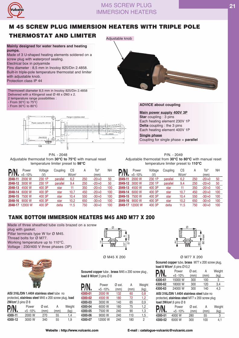
21
Website : http://www.vulcanic.com E-mail : [email protected]
Made of three sheathed tube coils brazed on a screwplug with gasket.Pillar terminals type W for Ø M45.Thread bolts for Ø M77.Working temperature up to 110°C.Voltage : 230/400 V three phases (3P)
Ø
A5719 57
max
i
Ø
A8030 80
max
i
Scoured copper tube, brass M77 x 200 screw plug,load 8 W/cm2 ,6 pins Ø10,2
P/N. Power Ø ext. A Weight+5 -10% (mm) (mm) (kg)
4300-61 15000 W 300 100 34300-62 18000 W 300 120 3,44300-63 24000 W 300 140 4,3AISI 316L/DIN 1.4404 stainless steel tube noprotected, stainless steel M77 x 200 screw plugload 2W/cm2,6 pins Ø 8
P/N. Power Ø ext. A Weight+5 -10% (mm) (mm) (kg)
4300-51 4000 W 280 55 34300-52 6000 W 300 100 4,1
Scoured copper tube , brass M45 x 200 screw plug ,load 8 W/cm2,3 pins Ø 8
P/N. Power Ø ext. A Weight+5 -10% (mm) (mm) (kg)
4300-01 2000 W 132 60 0,84300-02 4500 W 180 72 1,24300-03 3000 W 140 65 0,94300-04 6000 W 180 75 1,24300-05 7500 W 240 90 1,34300-06 9000 W 240 110 1,54300-07 12000 W 240 180 2
AISI 316L/DIN 1.4404 stainless steel tube noprotected, stainless steel M45 x 200 screw plug, load2W/cm2,3 pins Ø 8
P/N. Power Ø ext. A Weight+5 -10% (mm) (mm) (kg)
4300-11 2000 W 270 55 1,44300-12 3000 W 340 55 1,9
M45 SCREW PLUGIMMERSION HEATERS
TANK BOTTOM IMMERSION HEATERS M45 AND M77 X 200
P/N. Power Voltage Coupling CS A Tol* NH+5 -10% (V) W/cm2 (mm)
2048-11 2000 W 230 1P parallel 6,2 250 -20/+0 502048-12 3000 W 230 1P parallel 9,4 250 -20/+0 502048-13 4500 W 400 3P star 11 350 -20/+0 1002048-14 6000 W 400 3P star 10,7 450 -20/+0 1002048-15 7500 W 400 3P star 10,4 550 -30/+0 1002048-16 9000 W 400 3P star 10,2 650 -30/+0 1002048-17 12000 W 400 3P delta 11,5 750 -30/+0 100
P/N. Power Voltage Coupling CS A Tol* NH+5 -10% (V) W/cm2 (mm)
2049-11 2000 W 230 1P parallel 6,2 250 -20/+0 502049-12 3000 W 230 1P parallel 9,4 250 -20/+0 502049-13 4500 W 400 3P star 11 350 -20/+0 1002049-14 6000 W 400 3P star 10,7 450 -20/+0 1002049-15 7500 W 400 3P star 10,4 550 -30/+0 1002049-16 9000 W 400 3P star 10,2 650 -30/+0 1002049-17 12000 W 400 3P delta 11,5 750 -30/+0 100
P/N. - 2048Adjustable thermostat from 30°C to 75°C with manual reset
temperature limiter preset to 98°C
P/N. - 2049Adjustable thermostat from 30°C to 80°C with manual reset
temperature limiter preset to 110°C
ADVICE about coupling
Main power supply 400V 3PStar coupling : 3 pinsEach heating element 230V 1PDelta coupling : the 3 pinsEach heating element 400V 1PSingle phaseCoupling for single phase = parallel
Plastic casing 90 x 90 mm
Flange in stainless steel
BSPP
1"1/2
A
Gland ISO 20
Ø < 42mm
108
M 45 SCREW PLUG IMMERSION HEATERS WITH TRIPLE POLE
THERMOSTAT AND LIMITER
Ø M45 X 200 Ø M77 X 200
Mainly designed for water heaters and heatingpumps.Made of 3 U-shaped heating elements soldered on ascrew plug with waterproof sealing.Electrical box in polyamidePins diameter : 8,5 mm in Incoloy 825/Din 2.4858.Built-in triple-pole temperature thermostat and limiterwith adjustable knob.Protection class IP 44
Thermowell diameter 8,5 mm in Incoloy 825/Din 2.4858Delivered with a Klingersil seal Ø 48 x Ø60 x 2.2 temperature range possibilities :- From 30°C to 75°C- From 30°C to 80°C
Adjustable knob
Website : http://www.vulcanic.com E-mail : [email protected]
22
Website : http://www.vulcanic.com E-mail : [email protected]
M 77 SCREW PLUGIMMERSION HEATERS
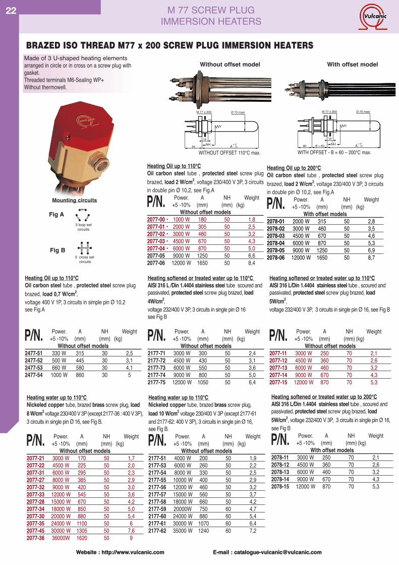
Made of 3 U-shaped heating elementsarranged in circle or in cross on a screw plug withgasket.Threaded terminals M6-Sealing WP+Without thermowell.
19
VVV
NcA94
M 77 x 200 Ø 70 maxi
NON OFFSET 110°C max- 15+ 0
Heating Oil up to 110°COil carbon steel tube , protected steel screw plugbrazed, load 2 W/cm2, voltage 230/400 V 3P, 3 circuitsin double pin Ø 10,2, see Fig.A
P/N. Power. A NH Weight+5 -10% (mm) (mm) (kg)
Without offset models2077-00 • 1000 W 180 50 1,82077-01 • 2000 W 305 50 2,52077-02 • 3000 W 460 50 3,22077-03 • 4500 W 670 50 4,32077-04 • 6000 W 870 50 5,02077-05 9000 W 1250 50 6,62077-06 12000 W 1650 50 8,4
Heating Oil up to 200°COil carbon steel tube , protected steel screw plugbrazed, load 2 W/cm2, voltage 230/400 V 3P, 3 circuitsin double pin Ø 10,2, see Fig.A
P/N. Power. A NH Weight+5 -10% (mm) (mm) (kg)
With offset models2078-01 2000 W 315 50 2,82078-02 3000 W 460 50 3,52078-03 4500 W 670 50 4,62078-04 6000 W 870 50 5,32078-05 9000 W 1250 50 6,92078-06 12000 W 1650 50 8,73 cross set
circuits
Fig B
Fig A
19
VVV
NcAB = 6080
M 77 x 200 Ø 70 maxi
OFFSET - B = 60 - 200°C max- 15+ 0
3 loop setcircuits
Heating water up to 110°CNickeled copper tube, brazed brass screw plug, load8 W/cm2 voltage 230/400 V 3P (except 2177-36 : 400 V 3P),3 circuits in single pin Ø 16, see Fig B.
P/N. Power. A NH Weight+5 -10% (mm) (mm) (kg)
Without offset models2077-21 3000 W 170 50 1,72077-22 4500 W 225 50 2,02077-31 6000 W 295 50 2,32077-27 8000 W 385 50 2,92077-32 9000 W 420 50 3,02077-33 12000 W 545 50 3,62077-28 15000 W 670 50 4,22077-34 18000 W 850 50 5,02077-30 20000 W 880 50 5,42077-35 24000 W 1100 50 62077-45 30000 W 1305 50 7,62077-36 36000W 1620 50 9
Heating water up to 110°CNickeled copper tube, brazed brass screw plug,load 10 W/cm2 voltage 230/400 V 3P (except 2177-61and 2177-62: 400 V 3P), 3 circuits in single pin Ø 16,see Fig B.
P/N. Power. A NH Weight+5 -10% (mm) (mm) (kg)
Without offset models2177-51 4000 W 200 50 1,92177-53 6000 W 260 50 2,22177-54 8000 W 330 50 2,52177-55 10000 W 400 50 2,92177-56 12000 W 460 50 3,22177-57 15000 W 560 50 3,72177-58 18000 W 660 50 4,22177-59 20000W 750 60 4,72177-60 24000 W 880 60 5,42177-61 30000 W 1070 60 6,42177-62 35000 W 1240 60 7,2
Heating softened or treated water up to 110°CAISI 316 L/Din 1.4404 stainless steel tube , scoured andpassivated, protected steel screw plug brazed, load5W/cm2,voltage 232/400 V 3P, 3 circuits in single pin Ø 16, see Fig B
P/N. Power. A NH Weight+5 -10% (mm) (mm) (kg)
Without offset models2077-11 3000 W 250 70 2,12077-12 4500 W 360 70 2,62077-13 6000 W 460 70 3,22077-14 9000 W 670 70 4,32077-15 12000 W 870 70 5,3
Heating softened or treated water up to 110°CAISI 316 L /Din 1.4404 stainless steel tube scoured andpassivated, protected steel screw plug brazed, load4W/cm2,voltage 232/400 V 3P, 3 circuits in single pin Ø 16see Fig B
P/N. Power. A NH Weight+5 -10% (mm) (mm) (kg)
Without offset models2177-71 3000 W 300 50 2,42177-72 4500 W 430 50 3,12177-73 6000 W 550 50 3,62177-74 9000 W 800 50 5,02177-75 12000 W 1050 50 6,4
BRAZED ISO THREAD M77 x 200 SCREW PLUG IMMERSION HEATERS
Heating Oil up to 110°COil carbon steel tube , protected steel screw plugbrazed, load 0,7 W/cm2,voltage 400 V 1P, 3 circuits in simple pin Ø 10,2see Fig.A
P/N. Power. A NH Weight+5 -10% (mm) (mm) (kg)
Without offset models2477-51 330 W 315 30 2,52477-52 500 W 445 30 3,12477-53 660 W 580 30 4,12477-54 1000 W 860 30 5
Mounting circuits
Without offset model With offset model
NH NH
Heating softened or treated water up to 200°CAISI 316 L/Din 1.4404 stainless steel tube , scoured andpassivated, protected steel screw plug brazed, load5W/cm2, voltage 232/400 V 3P, 3 circuits in single pin Ø 16,see Fig B
P/N. Power. A NH Weight+5 -10% (mm) (mm) (kg)
With offset models2078-11 3000 W 250 70 2,12078-12 4500 W 360 70 2,62078-13 6000 W 460 70 3,22078-14 9000 W 670 70 4,32078-15 12000 W 870 70 5,3
WITHOUT OFFSET 110°C max. WITH OFFSET - B = 60 – 200°C max.
Website : http://www.vulcanic.com E-mail : [email protected]
23
Website : http://www.vulcanic.com E-mail : [email protected] : http://www.vulcanic.com E-mail : [email protected]
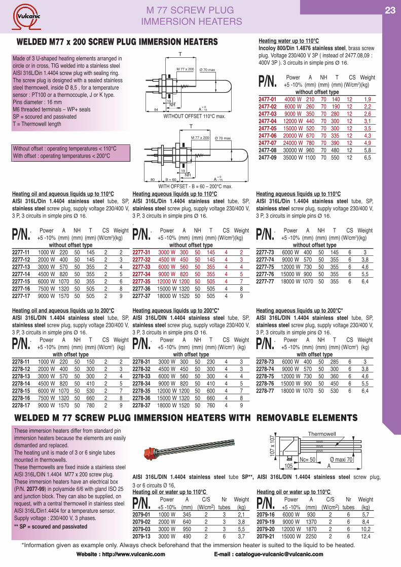
Made of 3 U-shaped heating elements arranged incircle or in cross, TIG welded into a stainless steelAISI 316L/Din 1.4404 screw plug with sealing ring.The screw plug is designed with a sealed stainlesssteel thermowell, inside Ø 8,5 , for a temperaturesensor : PT100 or a thermocouple, J or K type.Pins diameter : 16 mmM6 threaded terminals – WP+ sealsSP = scoured and passivatedT = Thermowell length
WELDED M77 x 200 SCREW PLUG IMMERSION HEATERS
Without offset : operating temperatures < 110°CWith offset : operating temperatures < 200°C
Heating oil and aqueous liquids up to 110°CAISI 316L/Din 1.4404 stainless steel tube, SP,stainless steel screw plug, supply voltage 230/400 V,3 P, 3 circuits in simple pins Ø 16.
P/N.. Power A NH T CS Weight+5 -10% (mm) (mm) (mm) (W/cm2)(kg)
without offset type2277-11 1000 W 220 50 145 2 22277-12 2000 W 400 50 145 2 32277-13 3000 W 570 50 355 2 42277-14 4500 W 820 50 355 2 52277-15 6000 W 1070 50 355 2 62277-16 7500 W 1320 50 505 2 82277-17 9000 W 1570 50 505 2 9
Heating oil and aqueous liquids up to 200°CAISI 316L/DIN 1.4404 stainless steel tube, SP,stainless steel screw plug, supply voltage 230/400 V,3 P, 3 circuits in simple pins Ø 16.
P/N.. Power A NH T CS Weight+5 -10% (mm) (mm) (mm) (W/cm2) (kg)
with offset type2278-11 1000 W 220 50 150 2 22278-12 2000 W 400 50 300 2 32278-13 3000 W 570 50 300 2 42278-14 4500 W 820 50 410 2 52278-15 6000 W 1070 50 530 2 72278-16 7500 W 1320 50 660 2 82278-17 9000 W 1570 50 780 2 9
Heating aqueous liquids up to 110°CAISI 316L/Din 1.4404 stainless steel tube, SP,stainless steel screw plug, supply voltage 230/400 V,3 P, 3 circuits in simple pins Ø 16..
P/N.. Power A NH T CS Weight+5 -10% (mm) (mm) (mm) (W/cm2)(kg)
without offset type2277-31 3000 W 300 50 145 4 22277-32 4500 W 450 50 145 4 32277-33 6000 W 560 50 355 4 42277-34 9000 W 820 50 355 4 52277-35 12000 W 1200 50 505 4 72277-36 15000 W 1320 50 505 4 82277-37 18000 W 1520 50 505 4 9
Heating aqueous liquids up to 200°C*AISI 316L/DIN 1.4404 stainless steel tube, SP,stainless steel screw plug, supply voltage 230/400 V,3 P, 3 circuits in simple pins Ø 16.
P/N.. Power A NH T CS Weight+5 -10% (mm) (mm) (mm) (W/cm2) (kg)
with offset type2278-31 3000 W 300 50 230 4 32278-32 4500 W 450 50 300 4 32278-33 6000 W 560 50 300 4 42278-34 9000 W 820 50 410 4 52278-35 12000 W 1200 50 600 4 72278-36 15000 W 1320 50 660 4 82278-37 18000 W 1520 50 760 4 9
Heating aqueous liquids up to 110°CAISI 316L/Din 1.4404 stainless steel tube, SP,stainless steel screw plug, supply voltage 230/400 V,3 P, 3 circuits in simple pins Ø 16.
P/N.. Power A NH T CS Weight+5 -10% (mm) (mm) (mm) (W/cm2)(kg)
without offset type2277-73 6000 W 400 50 145 6 32277-74 9000 W 570 50 355 6 3,82277-75 12000 W 730 50 355 6 4,62277-76 15000 W 900 50 355 6 5,52277-77 18000 W 1070 50 355 6 6,4
Heating aqueous liquids up to 200°C*AISI 316L/DIN 1.4404 stainless steel tube, SP,stainless steel screw plug, supply voltage 230/400 V,3 P, 3 circuits in simple pins Ø 16.
P/N.. Power A NH T CS Weight+5 -10% (mm) (mm) (mm) (W/cm2) (kg)
with offset type2278-73 6000 W 400 50 285 6 32278-74 9000 W 570 50 300 6 3,82278-75 12000 W 730 50 360 6 4,62278-76 15000 W 900 50 450 6 5,52278-77 18000 W 1070 50 530 6 6,4
Heating oil or water up to 110°C
P/N. Power A C/S Nr Weight+5 -10% (mm) (W/cm2) tubes (kg)
2079-01 1000 W 345 2 3 2,12079-02 2000 W 640 2 3 3,82079-03 3000 W 950 2 3 5,52079-13 3000 W 490 2 6 3,7
These immersion heaters differ from standard pinimmersion heaters because the elements are easilydismantled and replaced.The heating unit is made of 3 or 6 single tubesmounted in thermowells.These thermowells are fixed inside a stainless steelAISI 316L/DIN 1.4404 M77 x 200 screw plug.These immersion heaters have an electrical box(P/N. 2077-99) in polyamide 6/6 with gland ISO 25and junction block. They can also be supplied, onrequest, with a central thermowell in stainless steelAISI 316L/Din1.4404 for a temperature sensor.Supply voltage : 230/400 V, 3 phases.** SP = scoured and passivated
Heating oil or water up to 110°C
P/N. Power A C/S Nr Weight+5 -10% (mm) (W/cm2) tubes (kg)
2079-16 6000 W 930 2 6 5,72079-19 9000 W 1370 2 6 8,42079-20 12000 W 1870 2 6 10,22079-21 15000 W 2250 2 6 12,4
VVVVVVVVVVVV
Nc= 50 ¯ maxi 70A105
107 x
107 Doigts de gant ¯ 19Thermowell
AISI 316L/DIN 1.4404 stainless steel tube SP**, AISI 316L/DIN 1.4404 stainless steel screw plug,3 or 6 circuits Ø 16,
WELDED M 77 SCREW PLUG IMMERSION HEATERS WITH REMOVABLE ELEMENTS
Heating water up to 110°CIncoloy 800/Din 1.4876 stainless steel, brass screwplug. Voltage 230/400 V 3P ( instead of 2477.08,09 :400V 3P ). 3 circuits in simple pins Ø 16.
P/N. Power A NH T CS Weight+5 -10% (mm) (mm) (mm) (W/cm2)(kg)
without offset type2477-01 4000 W 210 70 140 12 1,92477-02 6000 W 260 70 190 12 2,22477-03 9000 W 350 70 280 12 2,62477-04 12000 W 440 70 300 12 3,12477-05 15000 W 520 70 300 12 3,52477-06 20000 W 670 70 335 12 4,32477-07 24000 W 780 70 390 12 4,92477-08 30000 W 960 70 480 12 5,82477-09 35000 W 1100 70 550 12 6,5
19
VVV
NcA94
M 77 x 200 Ø 70 max
NON OFFSET 110°C Max- 15+ 0
T
19
VVV
NcAB = 6080
M 77 x 200 Ø 70 max
OFFSET - B = 60 - 200°C Max- 15+ 0
T
M 77 SCREW PLUGIMMERSION HEATERS
NH
NH
WITHOUT OFFSET 110°C max.
WITH OFFSET - B = 60 – 200°C max.
*Information given as example only. Always check beforehand that the immersion heater is suited to the liquid to be heated.
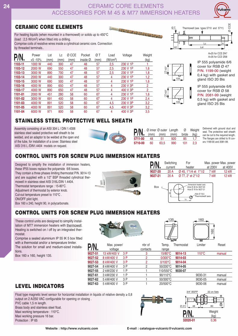
Website : http://www.vulcanic.com E-mail : [email protected]
24
Float type magnetic level sensor for horizontal installation in liquids of relative density ≥ 0,8output on 2 A/250 VAC configurable for opening or closing .PVC cable 1,5 m length.Brass body and stainless steel float.Maxi working temperature : 110°C.Maxi working pressure 16 bar.Protection : IP 65
Designed to simplify the installation of immersion heaters,these IP55 boxes replace the polyamide 6/6 boxes.They contain a three phases limiting thermostat P/N. 9014-13and are supplied with a 1/2” BSP threaded cylindrical ther-mowell in stainless steel AISI 316L/DIN 1.4404.Thermostat temperature range : 15-80°C.Adjustment of thermostat by exterior knob.Cut-out temperature preset to 110°C .ON/OFF pilot light.Box 160 x 240, height 90, in polycarbonate.
P/N. Switching For Max. power Max. powercurrent heater at 230V at 400V
9027-20 20 A Ø 45, 1“1/4 et 1"1/2 7 kW 12 kW9027-21 20 A Ø 77, 2“ et 2"1/2 7 kW 12 kW
69
70
Axes du thermoplongeur
Axes du doigt de gantPerçage Ø 16,5
Perçage Ø 46 pour 9027-20Perçage Ø 78 pour 9027-21
Boitier
These control units are designed to simplify instal-lation of M77 immersion heaters with thermowell.Heating is switched on / off by an integrated ther-mostat.Comprise a sealed aluminium IP 55 IK 5 box fittedwith a thermostat and/or a temperature limiter.The solution for small and medium-sized installa-tions.Box 160 x 160, height 135.
160
160135
P/N. Max. power/ nbr of Temp. Thermostat Limiter Resetvoltage contacts range
9027-51 13 kW/400 V 3 P 3 15/80°C 9014-13 110°C manual9027-52 8 kW/400 V 3 P 2 0/300°C 9014-039027-53 8 kW/400 V 3 P 2 0/100°C 9014-049027-54 8 kW/400 V 3 P 2 50/200°C 9014-059027-55 2 kW/230 V 1 P 1 110/550°C 9030-079027-61 3 kW/230 V 1 P 1 90/110°C 9030-31 manual9027-62 5 kW/400 V 3 P 1 50/300°C 9030-05 manual9027-63 5 kW/400 V 3 P 1 20/500°C 9030-06 manual
CONTROL UNITS FOR SCREW PLUG IMMERSION HEATERS
LEVEL INDICATORS
Immersion heater axisHole Ø 46 for 9027-20Hole Ø 78 for 9027-21
Hole Ø 16,5
For heating liquids (when mounted in a thermowell) or solids up to 450°C(load : 2,5 W/cm2) when fitted into a drilling.Comprise coils of resistive wires inside a cylindrical ceramic core. Connectionby threaded terminals..
P/N. Power Lst Lc Ø CCE Pocket Ø T Load Voltage Weight+5 -10% (mm) (mm) (mm) inside Ø. (mm) (W/cm2) (kg)
1103-11 1000 W 440 300 47 48 57 2,5 230 V 1P 11103-12 2000 W 690 550 47 48 57 2,5 230 V 1P 1,61103-13 3000 W 890 700 47 48 57 2,5 230 V 1P 1,81103-14 2000 W 440 300 47 48 57 4 230 V 1P 1,21103-15 3000 W 690 500 47 48 57 4 230 V 1P 1,61103-16 4000 W 890 650 47 48 57 4 230 V 3P 21103-17 4000 W 890 650 47 48 57 4 400 V 3P 21101-01 2000 W 451 280 58 60 67 4 230 V 1P 1,61101-02 3000 W 691 400 58 60 67 4 230 V 1P 2,41101-03 4000 W 891 520 58 60 67 4,5 230 V 3P 3,21101-05 4000 W 891 520 58 60 67 4,5 400 V 3P 3,21101-04 6000 W 971 800 58 60 67 4 400 V 3P 3,5
CERAMIC CORE ELEMENTS
105
107
IP 555 polyamide 6/6cover for RSB Ø 47P/N. 1199-00 (weight0,4 kg) with gasket andgland ISO 20 Bis
105
107
IP 555 polyamide 6/6cover for RSB Ø 58P/N. 2081-99 (weight0,5 kg) with gasket andgland ISO 25 Bis
P/N. Weight(kg)
32020-01 0,36
3/4" BSPP
48Ø 21 80
32 on flats
Doigt de gant (voir types 5710 et 5711)Ø T
42 LstLc A
ØRS
B
VVV
A=25 pour RSB Ø47A=35 pour RSB Ø58
Thermowell (see types 5710 and 5711)
A=25 for CCE Ø47A=35 for CCE Ø58
Assembly consisting of an AISI 304 L / DIN 1.4306stainless steel sealed protective well sheath to bewelded, and an adaptor to be welded at the open endof the tube, for installation of a cover. Stainless steelAISI 316 L /DIN1.4404 models on request.
P/N.. Ø inner Ø outer Length Ø Weight(mm) (mm) (mm) bride (kg)
5711-00 48 51 920 85 1,75710-00 60 63,5 990 101 2,3
Delivered with ground stud andseal. The protective well sheathcan be cut to the required length.The flanges are drilled to fit cov-ers 1199-00 and 2081-99.
STAINLESS STEEL PROTECTIVE WELL SHEATH
CONTROL UNITS FOR SCREW PLUG IMMERSION HEATERS
ØCC
E
Box
CERAMIC CORE ELEMENTSACCESSORIES FOR M 45 & M77 IMMERSION HEATERS
Thermowell axis

Website : http://www.vulcanic.com E-mail : [email protected]
25
Website : http://www.vulcanic.com E-mail : [email protected] : http://www.vulcanic.com E-mail : [email protected] : http://www.vulcanic.com E-mail : [email protected]
ACCESSORIES FOR M45 & M77IMMERSION HEATERS
ACCESSORIES FOR M 45 SCREW PLUG IMMERSION HEATERS.
105
107
Ø63
7 13 10Ø
55
60/p
lats
16360 on�flats 12 19 10
Ø2
Ø1
12 19 10Ø
2
Ø1
95on
�fla
ts
- P/N. 2045-99 : Swivelling boxIP 555 in 6/6 fibreglass reinforcedpolyamide with fixing screw,KLINGERSIL seal Iso 20 bis gland.(weight 0,4 kg).
- P/N. 9621-01 Swivelling box IP555in aluminium with fixing screw,KLINGERSIL seal and Iso 20 bis gland.(weight 0,5 kg)(Box 95 x 95, h=70)
- P/N. 9623-01 : Welding ring45x200 in mild carbon steel. (weight0,14 kg).- P/N. 9623-03 : Welding ring45x200 in stainless steel AISI304L/DIN 1.4306.
- P/N. 4509-99 : box spanner(supplied without tommy bar). (weight1,8 kg).- P/N. 9639-00 : Steel plug for seal-ing, or to allow welding without distor-tion of the sealing ring. P/N. 9623-01.(weight 0,4 kg).
- P/N. 9639-01 : Stainless steel 304 Lplug for sealing or to allow weldingwithout distortion of the welding ringP/N. 9623-03. Supplied withKLINGERSIL sealing ring. (weight 0,4kg).
- P/N. 4529-01 : Protected steel M 45x 200 screw. (weight 0,12 kg).
- P/N. 4527-01 : Mild steel reducer Ø1 =77 x 200 to Ø2 = 45 x 200 withKLINGERSIL sealing ring and screw.(weight 1,3 kg).- P/N. 51934-20 : Pack of 20KLINGERSIL sealing rings for M45.(weight 0,2 kg).- P/N. 51954-10 : Pack of 10 cop-per/composite fibre sealing rings forM45. (weight 0,1 kg).
105
107
For immersion heaters withoutthermowell- P/N. 2077-99 : Swivelling box IP555 in fibreglass reinforced 6/6polyamide with fixing screw,KLINGERSIL sealing ring and Iso 25gland.(weight 0,5 kg).- P/N. 2077-98 : Same box with Iso32 gland (instead of Iso 25) for pow-ers of 18 kW at 230V and 36 kW at400V. (weight 0,5 kg).- P/N. 9622-01 : Swivelling boxIP555 in aluminium with fixing screw,
KLINGERSIL sealing ring and Iso 25gland. (weight 0,6 kg).(Box 107 x 107, h=105)
Ø10
2
10 10 10
Ø90
95/p
lats
18596 on�flats
- P/N. 9624-01 : Mild carbon steelwelding ring 77x200 (weight 0,36 kg).- P/N. 9624-03 : Stainless steelAISI 304 L/DIN 1.4306 sealing ring(weight 0,36 kg).- P/N. 9624-04 : Stainless steel316 L/DIN 1.4404 sealing ring 77x200(weight 0,36 kg).- P/N. 4510-99 : Box wrench (suppliedwithout tommy bar) (weight 2,2 kg).- P/N. 9640-00 : Carbon steel plug forsealing or to allow sealing without distor-tion of the sealing ring 9624-0x. Suppliedwith KLINGERSIL sealing ring. (weight0,6 kg).- P/N. 9640-01 : Stainless steel AISI316L/DIN 1.4404 plug for sealing or toallow sealing without distortion of thewelding ring 9624-0x. Supplied withKLINGERSIL sealing ring (weight 0,6 kg).- P/N. 4529-02 : Protected steel screw,M 77 x 200. (weight 0,26 kg).
- P/N. 51938-20 : Pack of 20KLINGERSIL sealing rings for M77(weight 0,17 kg).- P/N. 51958-10 : Pack of 10 cop-per/composite fibre sealing rings forM77. (weight 0,17 kg).- P/N. 52704-50 : Pack of 50 con-necting clips for ring pattern circuits(weight 0,13 kg).- P/N. 52724-50 : Pack of 50 right-angled connecting clips for cross pat-tern circuits (weight 0,23 kg).- P/N. 52750-25 : Pack of 25 flat and25 right-angled connection clips(weight 0,18 kg)
ACCESSORIES FOR M 77 SCREW PLUG IMMERSION HEATERS
For immersion heaters with thermow-ell- P/N. 2077-97 : Swivelling boxIP 555 in 6/6 fibreglass reinforcedpolyamide with fixing screw,KLINGERSIL seal and Iso 16 bis andIso 25 gland (weight 0,5 kg).
- P/N. 2077-96 : Swivelling boxIP 555 in 6/6 fibreglass reinforcedpolyamide with fixing screw,KLINGERSIL seal and Iso 16 bis ansIso 32 gland. (weight 0,5 kg).
RESIN FOR TOTAL SEALING OF TERMINAL BOXESCompletely immerse an immersion heater ? It is perfectlypossible. Just fill the terminal box with this resin, once theconnections are made. Easy to use , the two-part resincomes in a packaging. Break the central partition, mix thecontents for a few moments, and the resin is ready toruse. Caution : do not use on an immersion heater with anintegral controller or a control box. If the supply cable isPTFE covered, wrap it first with elastomer ribbon toensure a perfect seal.
P/N. Description Volume or Weightlength (g)
56073-11 Resin 93ml 10056073-12 Resin 200ml 43056073-21 Elastomer ribbon 9,15m x 19mm 110
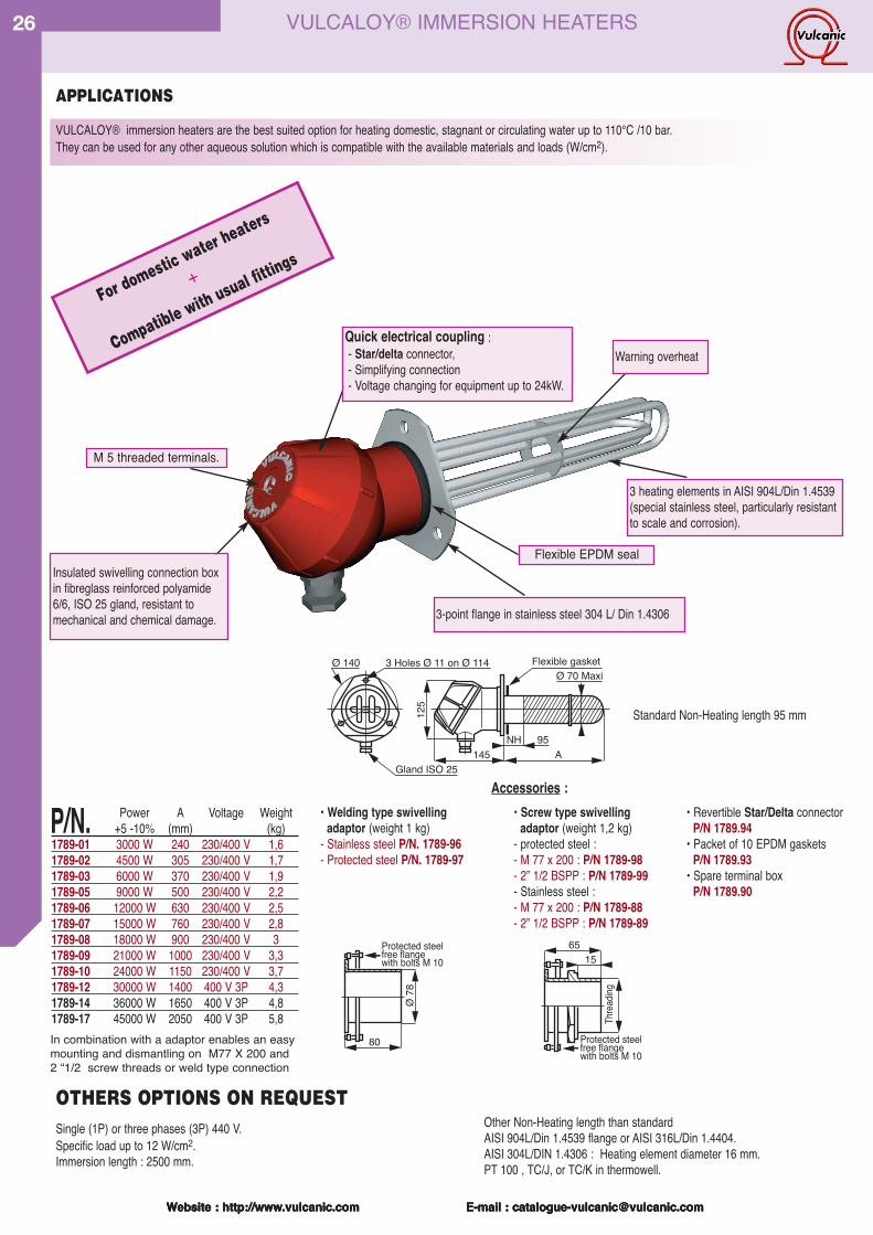
Website : http://www.vulcanic.com E-mail : [email protected]
26
VULCALOY® immersion heaters are the best suited option for heating domestic, stagnant or circulating water up to 110°C /10 bar.They can be used for any other aqueous solution which is compatible with the available materials and loads (W/cm2).
Warning overheatQuick electrical coupling :- Star/delta connector,- Simplifying connection- Voltage changing for equipment up to 24kW.
3 heating elements in AISI 904L/Din 1.4539(special stainless steel, particularly resistantto scale and corrosion).
3-point flange in stainless steel 304 L/ Din 1.4306
Insulated swivelling connection boxin fibreglass reinforced polyamide6/6, ISO 25 gland, resistant tomechanical and chemical damage.
Flexible EPDM seal
M 5 threaded terminals.
P/N. Power A Voltage Weight+5 -10% (mm) (kg)
1789-01 3000 W 240 230/400 V 1,61789-02 4500 W 305 230/400 V 1,71789-03 6000 W 370 230/400 V 1,91789-05 9000 W 500 230/400 V 2,21789-06 12000 W 630 230/400 V 2,51789-07 15000 W 760 230/400 V 2,81789-08 18000 W 900 230/400 V 31789-09 21000 W 1000 230/400 V 3,31789-10 24000 W 1150 230/400 V 3,71789-12 30000 W 1400 400 V 3P 4,31789-14 36000 W 1650 400 V 3P 4,81789-17 45000 W 2050 400 V 3P 5,8
VULCALOY® IMMERSION HEATERS
• Welding type swivellingadaptor (weight 1 kg)
- Stainless steel P/N. 1789-96- Protected steel P/N. 1789-97
Accessories :• Screw type swivelling
adaptor (weight 1,2 kg)- protected steel :- M 77 x 200 : P/N 1789-98- 2” 1/2 BSPP : P/N 1789-99- Stainless steel :- M 77 x 200 : P/N 1789-88- 2” 1/2 BSPP : P/N 1789-89
• Revertible Star/Delta connectorP/N 1789.94
• Packet of 10 EPDM gasketsP/N 1789.93
• Spare terminal boxP/N 1789.90
80
Ø78
Protected steelfree flangewith bolts M 10
6515
Threa
ding
Protected steelfree flangewith bolts M 10
Single (1P) or three phases (3P) 440 V.Specific load up to 12 W/cm2.Immersion length : 2500 mm.
OTHERS OPTIONS ON REQUEST
125
145 ANH 95
Ø 70 MaxiFlexible gasket3 Holes Ø 11 on Ø 114Ø 140
Gland ISO 25
Website : http://www.vulcanic.com E-mail : [email protected] : http://www.vulcanic.com E-mail : [email protected] : http://www.vulcanic.com E-mail : [email protected]
APPLICATIONS
Fordom
estic wa
ter heate
rs
+
Compati
blewith
usual fitt
ings
Other Non-Heating length than standardAISI 904L/Din 1.4539 flange or AISI 316L/Din 1.4404.AISI 304L/DIN 1.4306 : Heating element diameter 16 mm.PT 100 , TC/J, or TC/K in thermowell.
Standard Non-Heating length 95 mm
In combination with a adaptor enables an easymounting and dismantling on M77 X 200 and2 “1/2 screw threads or weld type connection
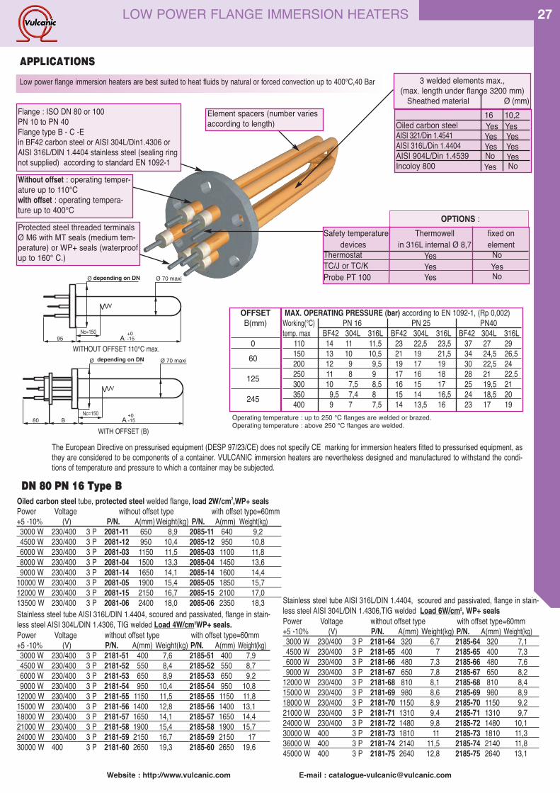
27
Website : http://www.vulcanic.com E-mail : [email protected]
MAX. OPERATING PRESSURE (bar) according to EN 1092-1, (Rp 0,002)Working(°C) PN 16 PN 25 PN40temp. max BF42 304L 316L BF42 304L 316L BF42 304L 316L
110 14 11 11,5 23 22,5 23,5 37 27 29150 13 10 10,5 21 19 21,5 34 24,5 26,5200 12 9 9,5 19 17 19 30 22,5 24250 11 8 9 17 16 18 28 21 22,5300 10 7,5 8,5 16 15 17 25 19,5 21350 9,5 7,4 8 15 14 16,5 24 18,5 20400 9 7 7,5 14 13,5 16 23 17 19
Protected steel threaded terminalsØ M6 with MT seals (medium tem-perature) or WP+ seals (waterproofup to 160° C.)
Without offset : operating temper-ature up to 110°Cwith offset : operating tempera-ture up to 400°C
Element spacers (number variesaccording to length)
Flange : ISO DN 80 or 100PN 10 to PN 40Flange type B - C -Ein BF42 carbon steel or AISI 304L/Din1.4306 orAISI 316L/DIN 1.4404 stainless steel (sealing ringnot supplied) according to standard EN 1092-1
DDNN 8800 PPNN 1166 TTyyppee BBOiled carbon steel tube, protected steel welded flange, load 2W/cm2,WP+ sealsPower Voltage without offset type with offset type=60mm+5 -10% (V) P/N. A(mm) Weight(kg) P/N. A(mm) Weight(kg)3000 W 230/400 3 P 2081-11 650 8,9 2085-11 640 9,2 4500 W 230/400 3 P 2081-12 950 10,4 2085-12 950 10,86000 W 230/400 3 P 2081-03 1150 11,5 2085-03 1100 11,88000 W 230/400 3 P 2081-04 1500 13,3 2085-04 1450 13,69000 W 230/400 3 P 2081-14 1650 14,1 2085-14 1600 14,4
10000 W 230/400 3 P 2081-05 1900 15,4 2085-05 1850 15,712000 W 230/400 3 P 2081-15 2150 16,7 2085-15 2100 17,013500 W 230/400 3 P 2081-06 2400 18,0 2085-06 2350 18,3Stainless steel tube AISI 316L/DIN 1.4404, scoured and passivated, flange in stain-less steel AISI 304L/DIN 1.4306, TIG welded Load 4W/cm2WP+ seals.Power Voltage without offset type with offset type=60mm+5 -10% (V) P/N. A(mm) Weight(kg) P/N. A(mm) Weight(kg)3000 W 230/400 3 P 2181-51 400 7,6 2185-51 400 7,94500 W 230/400 3 P 2181-52 550 8,4 2185-52 550 8,76000 W 230/400 3 P 2181-53 650 8,9 2185-53 650 9,29000 W 230/400 3 P 2181-54 950 10,4 2185-54 950 10,8
12000 W 230/400 3 P 2181-55 1150 11,5 2185-55 1150 11,815000 W 230/400 3 P 2181-56 1400 12,8 2185-56 1400 13,118000 W 230/400 3 P 2181-57 1650 14,1 2185-57 1650 14,421000 W 230/400 3 P 2181-58 1900 15,4 2185-58 1900 15,724000 W 230/400 3 P 2181-59 2150 16,7 2185-59 2150 1730000 W 400 3 P 2181-60 2650 19,3 2185-60 2650 19,6
Stainless steel tube AISI 316L/DIN 1.4404, scoured and passivated, flange in stain-less steel AISI 304L/DIN 1.4306,TIG welded Load 6W/cm2, WP+ sealsPower Voltage without offset type with offset type=60mm+5 -10% (V) P/N. A(mm) Weight(kg) P/N. A(mm) Weight(kg)3000 W 230/400 3 P 2181-64 320 6,7 2185-64 320 7,14500 W 230/400 3 P 2181-65 400 7 2185-65 400 7,36000 W 230/400 3 P 2181-66 480 7,3 2185-66 480 7,69000 W 230/400 3 P 2181-67 650 7,8 2185-67 650 8,2
12000 W 230/400 3 P 2181-68 810 8,1 2185-68 810 8,415000 W 230/400 3 P 2181-69 980 8,6 2185-69 980 8,918000 W 230/400 3 P 2181-70 1150 8,9 2185-70 1150 9,221000 W 230/400 3 P 2181-71 1310 9,4 2185-71 1310 9,724000 W 230/400 3 P 2181-72 1480 9,8 2185-72 1480 10,130000 W 400 3 P 2181-73 1810 11 2185-73 1810 11,336000 W 400 3 P 2181-74 2140 11,5 2185-74 2140 11,845000 W 400 3 P 2181-75 2640 12,8 2185-75 2640 13,1
Low power flange immersion heaters are best suited to heat fluids by natural or forced convection up to 400°C,40 Bar
The European Directive on pressurised equipment (DESP 97/23/CE) does not specify CE marking for immersion heaters fitted to pressurised equipment, asthey are considered to be components of a container. VULCANIC immersion heaters are nevertheless designed and manufactured to withstand the condi-tions of temperature and pressure to which a container may be subjected.
16 10,2Oiled carbon steel Yes YesAISI 321/Din 1.4541 Yes YesAISI 316L/Din 1.4404 Yes YesAISI 904L/Din 1.4539 No YesIncoloy 800 Yes No
OFFSETB(mm)
060
125
245
OPTIONS :
3 welded elements max.,(max. length under flange 3200 mm)
Sheathed material Ø (mm)
OFFSET
depending on DN
depending on DN
NON OFFSET
LOW POWER FLANGE IMMERSION HEATERS
Operating temperature : up to 250 °C flanges are welded or brazed.Operating temperature : above 250 °C flanges are welded.
Safety temperature Thermowell fixed ondevices in 316L internal Ø 8,7 element
Thermostat Yes NoTC/J or TC/K Yes YesProbe PT 100 Yes No
WITHOUT OFFSET 110°C max.
WITH OFFSET (B)
APPLICATIONS
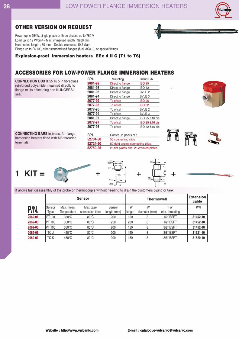
Website : http://www.vulcanic.com E-mail : [email protected]
28
Power up to 75kW, single phase or three phases up to 750 V Load up to 12 W/cm2 – Max. immersed length : 3200 mmNon-heated length : 30 mm – Double elements, 10.2 diamFlange up to PN100, other standardised flanges (fuel, ASA...), or special fittings.
LOW POWER FLANGE IMMERSION HEATERS
CONNECTING BARS in brass, for flangeimmersion heaters fitted with M6 threaded terminals.
CONNECTION BOX IP55 IK 5 in fibreglass reinforced polyamide, mounted directly toflange or to offset plug and KLINGERSILseal.
ACCESSORIES FOR LOW-POWER FLANGE IMMERSION HEATERSP/N. Mounting Gland P/N.2081-99 Direct to flange ISO 252081-98 Direct to flange ISO 322081-95 Direct to flange BVLE 22081-94 Direct to flange BVLE 32077-99 To offset ISO 252077-98 To offset ISO 322077-95 To offset BVLE 22077-94 To offset BVLE 32081-97 Direct to flange ISO 25 &16 bis2077-97 To offset ISO 25 &16 bis2077-96 To offset ISO 32 &16 bis
P/N. Coated, in packs of :52704-50 50 connecting clips52724-50 50 right angles connecting clips.52750-25 25 flat plates and .25 cranked plates.
Explosion-proof immersion heaters EEx d II C (T1 to T6)
OTHER VERSION ON REQUEST
1/2"BSPP
ØR
L
ØD1
ØD2
ØR
ØD9
117
1 KIT = + + +
P/N. Sensor Max. meas. Max case Sensor TW TW TW P/N.Type Temperature connection time length (mm) length diameter (mm) inter. threading
2062-01 PT100 350°C 80°C 200 100 8 1/2” BSPT 31452-102062-03 PT 100 350°C 80°C 250 200 8 1/2” BSPT 31452-102062-05 PT 100 350°C 80°C 200 150 8 3/8” BSPT 31452-102062-06 TC J 450°C 80°C 200 150 8 3/8” BSPT 31621-102062-07 TC K 450°C 80°C 200 150 8 3/8” BSPT 31620-10
Sensor Thermowell Extensioncable
Website : http://www.vulcanic.com E-mail : [email protected] : http://www.vulcanic.com E-mail : [email protected] : http://www.vulcanic.com E-mail : [email protected]
It allows fast disassembly of the probe or thermocouple without needing to drain the customers piping or tank
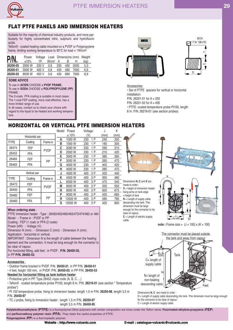
Website : http://www.vulcanic.com E-mail : [email protected]
29
Website : http://www.vulcanic.com E-mail : [email protected] : http://www.vulcanic.com E-mail : [email protected] : http://www.vulcanic.com E-mail : [email protected]
Suitable for the majority of chemical industry products, and more par-ticularly for highly concentrated nitric, sulphuric and hydrofluoricacids.Teflon®- -coated heating cable mounted on a PVDF or Polypropyleneframe, limiting working temperature to 90°C for load < 1W/cm2.
Accessories:• Set of PTFE spacers for vertical or horizontalinstallation.P/N. 26201-01 for A = 250P/N. 26201-02 for A = 430• PTFE -coated temperature probe Pt100, length8 m. P/N. 26216-01 (see section probes)
FLAT PTFE PANELS AND IMMERSION HEATERS
Accessories :• Outdoor frame bracket in PVDF. P/N. 26450.01, in PP P/N. 26450-51• 4 feet, height 100 mm, in PVDF. P/N. 26450-03, in PP P/N. 26450-53Needed for horizontal fitting as tank bottom heater• Protective grid in PP. Type 26452 +type code (A, B, C …)• Teflon® -coated temperature probe Pt100, length 8 m. P/N. 26216-01 (see section “ Temperatureprobes”)• Pt 100 temperature probe, fixing to immersion heater, length 1,5 m P/N. 26250-98, length 3,5 mP/N. 26450-97• TC J probe, fixing to immersion heater : length 1,5 m P/N. 26250-97
length 3,5 m P/N. 26450-95
When ordering state : PTFE immersion heater : Type : 26450/453/460/463/472/474/482 or 484Model : - Frame in : PVDF or PPCoating : FEP (1 coat) or PFA (2 coats)Power (kW) : - Voltage (V):Dimension N (mm) : - Dimension C (mm): - Dimension X (mm):Application : horizontal or vertical.IMPORTANT : Dimension N is the length of cable between the heatingelement and the connection. It must be long enough for the connector tobe clear of vapour.For horizontal fitting, add feet : in PVDF , P/N. 26450-03, in PP P/N. 26450-53.
Pieds
Le connecteur doit impérativement étre placéhors de la cuve et hors présence vapeurs
Cuve
C=longueurdu câbled'alimentation
N=longueurnon chauffantede remontée
200
N
C
P/N. Power Voltage Load Dimensions (mm) Weight±10% 1P. W/cm2 A B H (kg)
26200-05 2000 W 230 V 0,8 250 430 5000 5,326200-01 5000 W 400 V 0,8 430 580 7000 6,926200-02 8000 W 400 V 0,8 430 890 7000 8,9
Model Power Voltage J K± 10% (V) (mm) (mm)
A 1000 W 230 1 P 240 250B 1000 W 230 1 P 185 305C 2000 W 230 1 P 295 315D 2000 W 230 1 P 210 420E 3000 W 230 1 P 385 395F 3000 W 230 1 P 265 470G 4000 W 230 1 P 405 420H 4000 W 230 1 P 285 475J 4500 W 400 3 P 420 440K 4500 W 400 3 P 305 480L 6000 W 400 3 P 475 540M 6000 W 400 3 P 350 550N 9000 W 400 3 P 600 675P 9000 W 400 3 P 425 685R 12000 W 400 3 P 585 785S 12000 W 400 3 P 425 800
Utilisation HorizontaleCadre en
PVDF
PP
FEP 1 couche26474264532648426463
FEP 1 couchePFA 2 couches
PFA 2 couches
Gaine enN° Type
Utilisation VerticaleCadre en
PVDF
PP
FEP 1 couche26472264502648226460
FEP 1 couchePFA 2 couches
PFA 2 couches
Gaine enN° Type
note : Frame size = (J + 100) x (K + 100)
TYPEHorizontal useCoating Frame in
FEP2 coats1 coat 2 coats
TYPEVertical useCoating Frame in
1 coat 2 coats
1 coat 2 coats
The connector must be placed outside the tank and away from vapour
C= length ofsupply cable
N= length of non-heating
descending cable
Tank
Feet
PTFE IMMERSION HEATERS
Dimensions N, C are made to order :N = Length of supply cable descending into tank. This dimension must be large enoughfor the connector to be clear of vapour.C = Length of electric supply cable.
Dimensions N, C and X aremade to order :X = height of immersion heaterfixing arms on tank edge< height of tank.N = Length of supply cabledescending into tank. Thisdimension must be largeenough for the connector to beclear of vapour.C = Length of electric supplycable.
FEP
FEP
FEP
PFA
PFA
PFA
PFA
HORIZONTAL OR VERTICAL PTFE IMMERSION HEATERS
Polytetrafluoroethylene (PTFE) is a fluoropolymer.Other polymers with similar composition are know under the Teflon name: Fluorinated ethylene-propylene (FEP) and perfluoroalkoxy polymer resin (PFA). They retain the useful properties of PTFE.Polypropylene (PP) is a thermoplastic polymer.
SOME ADVICE To use in ACIDS CHOOSE a PVDF FRAME.To use in SODA CHOOSE a POLYPROPYLENE (PP)FRAME.The 2-coats PFA coating is suitable in most cases.The 1-coat FEP coating, more cost-effective, has amore limited range of use.In all cases, contact us to check your choice withregard to the liquid to be heated and working tempera-ture.
BOX

Website : http://www.vulcanic.com E-mail : [email protected]
30
Website : http://www.vulcanic.com E-mail : [email protected] : http://www.vulcanic.com E-mail : [email protected] : http://www.vulcanic.com E-mail : [email protected]
. Type Coating Frame in26495 FEP PVDF26458 PFA PVDF26497 FEP PP26468 PFA PP
When ordering state : PTFE immersion heater : Type :Model : - Frame in : PVDF or PPPower (kW) : - Voltage (V) : - Dimension N (mm) : - Dimension C (mm): - Dimension H (mm) : -IMPORTANT : Dimension N is the length of cable between the heating element and the connection. It must be long enough for the connector to be clear of vapour.
Heating element
Natural con-vection of
stored liquid
Storage tank
Manhole
Especially suited for frost protection and made of fluo-ropolymer,the circular heaters allow to heat or maintaintemperature of corrosive chemical baths in storage tanks.The flexible heating element is fixed to a flexible circularsupport. This form allows to be inserted into a tankthrough a ʻmanholeʼ.Diam 200mm min.with models A to F Diam 500mm .min with models G to K.Circular PTFE heaters offer a simple, economical solutionfor heating liquids in storage tanks.Made of Teflon ® Load 1 W/cm2, max. temperature 90°C, without gland.
CIRCULAR PTFE TANK BOTTOM HEATERS
Model Ø Element Power Voltage(mm) (kW) (V)
A 600 1 230 1 PB 600 2 230 1 PC 900 1 230 1 PD 900 3 230 1 PE 1100 1 230 1 PF 1100 6 400 3 PG 1500 2 230 1 PH 1500 9 400 3 PJ 1900 3 230 1 PK 1900 12 400 3 P
Important : Types 26458 A to K are supplied without gland (90°Cmax.) ; other models can be operated up to 100°C when fitted witha sealing gland.Other options on request : single phase or three phase voltage,intermediate powers and loads, cable entry via gland or flange.Teflon® -coated PT 100 probe or TC/J thermocouple positioned onthe descending supply cable. Dimensions N and C are tailor made.
CYLINDRICAL PTFE IMMERSION HEATERS
TEFLON® COATED PT100 PROBES
IMPORTANT : The heating area must be covered byat least 20 cm of liquid.
Dimensions N,C and X are made to order
Model Power Voltage A ØD± 10% (V) (mm) (mm)
A 1000 W 230 1 P 280 85B 2000 W 230 1 P 410 85C 3000 W 230 1 P 650 85D 4000 W 230 1 P 780 85E 4500 W 400 3 P 630 120F 6000 W 400 3 P 1140 85G 9000 W 400 3 P 1200 120H 12000 W 400 3 P 1395 120
P/N. L(m)
31170-01 0,531170-02 1,031170-03 1,531170-04 2,0
P/N.Plonger Type ofmaterial probe
31981-02 PVDF Pt100 - 3 wires31981-04 PVDF TC/J31981-05 PVDF TC/K31981-07 PP Pt100 - 3 wires31981-09 PP TC/J31981-10 PP TC/K
Horizontal fittingType Coating in Frame in
26477 FEP PVDF26456 PFA PVDF26487 FEP PP26466 PFA PP
Vertical fittingP/N. Type Coating in Frame in
26475 FEP PVDF26451 PFA PVDF26485 FEP PP26461 PFA PP
When ordering state :PTFE immersion heater : Type :Model : - Frame in : PVDF or PPPower (kW) : - Voltage (V): Dimension N (mm) : - Dimension C (mm): - Dimension X (mm)Horizontal or vertical fitting.IMPORTANT : Dimension N is the length of cable between the heat-ing element and the connection. It must be long enough for the con-nector to be out of emanations.
Horizontal fittingVerticalfitting
These probes mounted on a holder in PVDF essen-tial complement for the PTFE immersion heaters.Designed to be mounted on the tank edge.Theyallow to measure the temperature of the heated fluid.Several models are available to fit on different tanks.Connection leads : 1m.
Thermocouples or PT100 Teflon coated probes mountedon plonger with a sealing gland in PVDF or in PP.Standard length 0,5 m available up to 5m.Connection leads : 1m.
RIGID PROBES WITH PLONGER
0,5
to 5
m
PTFE IMMERSION HEATERS
38L
715
4886
ProbePolytetrafluoroethylene (PTFE) is a fluoropolymer.Other polymers with simi-lar composition are know under the Teflon name: Fluorinated ethylene-propylene (FEP) and perfluoroalkoxy polymer resin (PFA). They retainthe useful properties of PTFE.Polypropylene (PP) is a thermoplastic polymer.
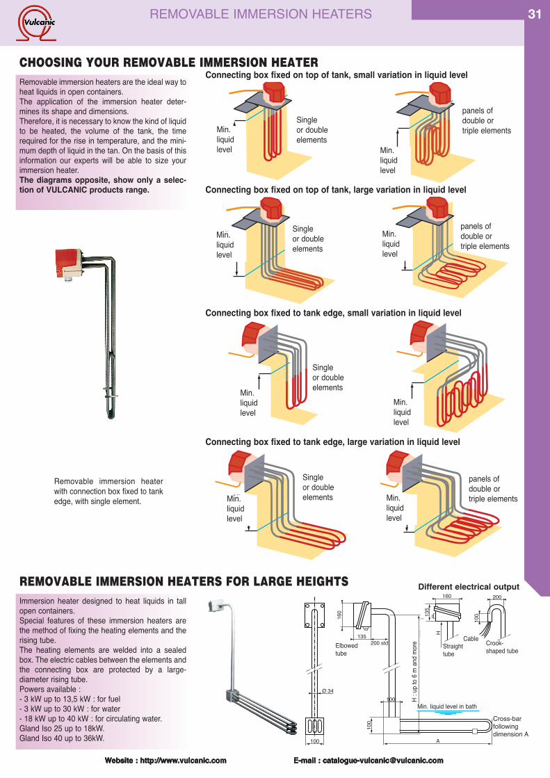
Website : http://www.vulcanic.com E-mail : [email protected]
31
Website : http://www.vulcanic.com E-mail : [email protected] : http://www.vulcanic.com E-mail : [email protected] : http://www.vulcanic.com E-mail : [email protected]
Removable immersion heaters are the ideal way toheat liquids in open containers.The application of the immersion heater deter-mines its shape and dimensions.Therefore, it is necessary to know the kind of liquidto be heated, the volume of the tank, the timerequired for the rise in temperature, and the mini-mum depth of liquid in the tan. On the basis of thisinformation our experts will be able to size yourimmersion heater.The diagrams opposite, show only a selec-tion of VULCANIC products range.
Immersion heater designed to heat liquids in tallopen containers.Special features of these immersion heaters arethe method of fixing the heating elements and therising tube.The heating elements are welded into a sealedbox. The electric cables between the elements andthe connecting box are protected by a large-diameter rising tube.Powers available :- 3 kW up to 13,5 kW : for fuel- 3 kW up to 30 kW : for water- 18 kW up to 40 kW : for circulating water.Gland Iso 25 up to 18kW.Gland Iso 40 up to 36kW.
REMOVABLE IMMERSION HEATERS FOR LARGE HEIGHTS
Niveaumini duliquide
Niveaumini duliquide
Niveaumini duliquide
Niveaumini duliquide
Niveaumini duliquide
Niveaumini duliquide
Niveaumini duliquide
Niveaumini duliquide
Niveaumini duliquide
Niveaumini duliquide
Niveaumini duliquide
Niveaumini duliquide
Niveaumini duliquide
Niveaumini duliquide
Niveaumini duliquide
Niveaumini duliquide
Niveaumini duliquide
Niveaumini duliquide
Niveaumini duliquide
Niveaumini duliquide
Niveaumini duliquide
Niveaumini duliquide
Niveaumini duliquide
Niveaumini duliquide
Niveaumini duliquide
Niveaumini duliquide
Niveaumini duliquide
Niveaumini duliquide
Niveaumini duliquide
Niveaumini duliquide
Niveaumini duliquide
Niveaumini duliquide
Connecting box fixed on top of tank, small variation in liquid level
Connecting box fixed on top of tank, large variation in liquid level
Niveaumini duliquide
Niveaumini duliquide
Niveaumini duliquide
Niveaumini duliquide
Niveaumini duliquide
Niveaumini duliquide
Niveaumini duliquide
Niveaumini duliquide
Niveaumini duliquide
Niveaumini duliquide
Niveaumini duliquide
Niveaumini duliquide
Niveaumini duliquide
Niveaumini duliquide
Niveaumini duliquide
Niveaumini duliquide
Connecting box fixed to tank edge, small variation in liquid level
Niveaumini duliquide
Niveaumini duliquide
Niveaumini duliquide
Niveaumini duliquide
Niveaumini duliquide
Niveaumini duliquide
Niveaumini duliquide
Niveaumini duliquide
Niveaumini duliquide
Niveaumini duliquide
Niveaumini duliquide
Niveaumini duliquide
Niveaumini duliquide
Niveaumini duliquide
Niveaumini duliquide
Niveaumini duliquide
Connecting box fixed to tank edge, large variation in liquid level
Single or doubleelements
Removable immersion heaterwith connection box fixed to tankedge, with single element.
Single or doubleelements
Single or doubleelements
Single or doubleelements
panels ofdouble or triple elements
panels ofdouble or triple elements
200
100
CâbleT en crosse
Niveau mini du bain
Entretoisesuivante cote A10
0
160
135
H
Tube droit
(mult
iple
de 1
00 m
m)
A
100
160
135200 stdTube coudé
Ø 34 H
100
CHOOSING YOUR REMOVABLE IMMERSION HEATER
panels ofdouble or triple elements
Min.liquidlevel
Min.liquidlevel
Min.liquidlevel
Min.liquidlevel
Min.liquidlevel
Min.liquidlevel
Min.liquidlevel
Min.liquidlevel
Crook-shaped tube
Min. liquid level in bath
H : u
p to 6
m an
d more Straight
tubeElbowedtube
Cable
REMOVABLE IMMERSION HEATERS
Cross-barfollowingdimension A
Different electrical output
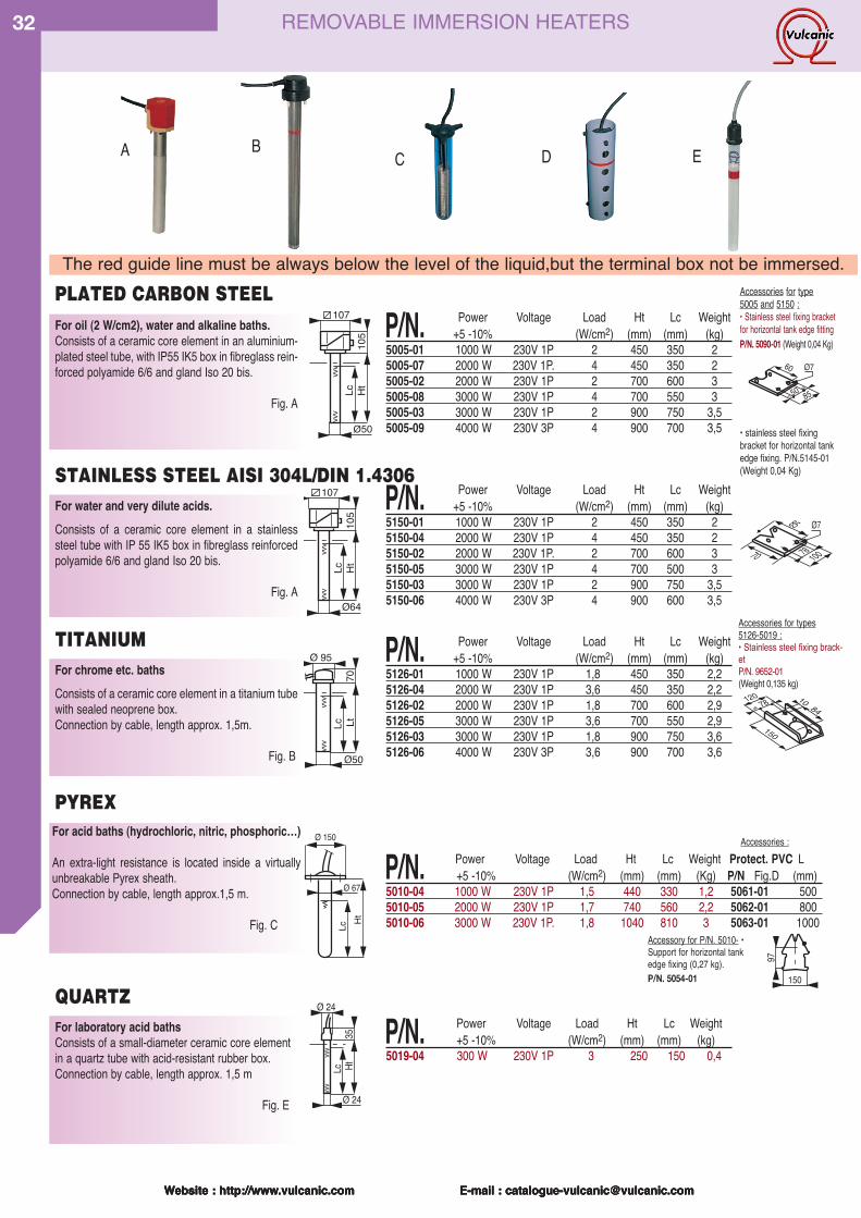
Website : http://www.vulcanic.com E-mail : [email protected]
32
Website : http://www.vulcanic.com E-mail : [email protected] : http://www.vulcanic.com E-mail : [email protected] : http://www.vulcanic.com E-mail : [email protected]
HtLc
Ø 67
Ø 150For acid baths (hydrochloric, nitric, phosphoric…)
An extra-light resistance is located inside a virtuallyunbreakable Pyrex sheath.Connection by cable, length approx.1,5 m.
Fig. C
PYREX
C
P/N. Power Voltage Load Ht Lc Weight Protect. PVC L +5 -10% (W/cm2) (mm) (mm) (Kg) P/N Fig.D (mm)
5010-04 1000 W 230V 1P 1,5 440 330 1,2 5061-01 5005010-05 2000 W 230V 1P 1,7 740 560 2,2 5062-01 8005010-06 3000 W 230V 1P. 1,8 1040 810 3 5063-01 1000
105
HtLc
Ø50
107For oil (2 W/cm2), water and alkaline baths.Consists of a ceramic core element in an aluminium-plated steel tube, with IP55 IK5 box in fibreglass rein-forced polyamide 6/6 and gland Iso 20 bis.
Fig. A
105
HtLc
Ø64
107
Ø 95
Ø50
70Lc Lt
For water and very dilute acids.Consists of a ceramic core element in a stainlesssteel tube with IP 55 IK5 box in fibreglass reinforcedpolyamide 6/6 and gland Iso 20 bis.
Fig. A
For chrome etc. bathsConsists of a ceramic core element in a titanium tubewith sealed neoprene box.Connection by cable, length approx. 1,5m.
Fig. B
12078 10 84
150
10078
85 Ø7
70
Accessories for type5005 and 5150 :• Stainless steel fixing bracketfor horizontal tank edge fittingP/N. 5090-01 (Weight 0,04 Kg)
• stainless steel fixingbracket for horizontal tankedge fixing. P/N.5145-01(Weight 0,04 Kg)
85
60
50
Ø7
Accessories for types5126-5019 :• Stainless steel fixing brack-etP/N. 9652-01 (Weight 0,135 kg)
Accessories :
For laboratory acid bathsConsists of a small-diameter ceramic core elementin a quartz tube with acid-resistant rubber box.Connection by cable, length approx. 1,5 m
Fig. E
Ø 24
Ø 24
35HtLc
STAINLESS STEEL AISI 304L/DIN 1.4306
TITANIUM
PLATED CARBON STEEL
QUARTZ
A B D E
The red guide line must be always below the level of the liquid,but the terminal box not be immersed.
P/N. Power Voltage Load Ht Lc Weight+5 -10% (W/cm2) (mm) (mm) (kg)
5005-01 1000 W 230V 1P 2 450 350 25005-07 2000 W 230V 1P. 4 450 350 25005-02 2000 W 230V 1P 2 700 600 35005-08 3000 W 230V 1P 4 700 550 35005-03 3000 W 230V 1P 2 900 750 3,55005-09 4000 W 230V 3P 4 900 700 3,5
P/N. Power Voltage Load Ht Lc Weight+5 -10% (W/cm2) (mm) (mm) (kg)
5150-01 1000 W 230V 1P 2 450 350 25150-04 2000 W 230V 1P 4 450 350 25150-02 2000 W 230V 1P. 2 700 600 35150-05 3000 W 230V 1P 4 700 500 35150-03 3000 W 230V 1P 2 900 750 3,55150-06 4000 W 230V 3P 4 900 600 3,5
P/N. Power Voltage Load Ht Lc Weight+5 -10% (W/cm2) (mm) (mm) (kg)
5126-01 1000 W 230V 1P 1,8 450 350 2,25126-04 2000 W 230V 1P 3,6 450 350 2,25126-02 2000 W 230V 1P 1,8 700 600 2,95126-05 3000 W 230V 1P 3,6 700 550 2,95126-03 3000 W 230V 1P 1,8 900 750 3,65126-06 4000 W 230V 3P 3,6 900 700 3,6
P/N. Power Voltage Load Ht Lc Weight+5 -10% (W/cm2) (mm) (mm) (kg)
5019-04 300 W 230V 1P 3 250 150 0,4
Accessory for P/N. 5010- •Support for horizontal tankedge fixing (0,27 kg).P/N. 5054-01 150
97
REMOVABLE IMMERSION HEATERS
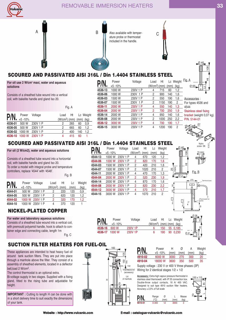
Website : http://www.vulcanic.com E-mail : [email protected]
33
Website : http://www.vulcanic.com E-mail : [email protected] : http://www.vulcanic.com E-mail : [email protected] : http://www.vulcanic.com E-mail : [email protected]
For oil use 2 W/cm2 maxi, water and aqueoussolutions
Consists of a sheathed tube wound into a verticalcoil, with bakelite handle and gland Iso 20.
Fig. A
Ø 40
Ø 65
108
HtLc
Ø 40
Ø Lc
108
Ht
25 mini
Accessories :For types 4536 and4544Stainless steel fixingbracket (weight 0,07 kg).P/N. 5144-01
Fig. A
Fig. B
For oil (2 W/cm2), water and aqueous solutions
Consists of a sheathed tube wound into a horizontalcoil, with bakelite handle and gland Iso 20.To order a model with integral probe and temperaturecontrollers, replace ʻ4544ʼ with ʻ4548ʼ.
Fig. B
Ø 28
Ø 41
70Ht
Lc
30
46 30
58
Ø7
Visserie Ø6en nylon
15 mini
For water and laboratory aqueous solutionsConsists of a sheathed tube wound into a vertical coil,with premould polyamid handle, hook to attach to con-tainer edge and connecting cable, length 1m
Fig. C
These appliances are intended to heat heavy fuel oilaround tank suction filters. They are put into placethrough a manhole above the filter. They consist of aassembly of sheathed elements, located in a deflectorbell,load 2 W/cm2.The control thermostat is an optional extra.Bi-voltage supply in two stages. Supplied with a fixinggland, fitted to the rising tube and adjustable forheight.
A
Ø
135
150
mini
160
THERMOSTAT(accessoire)
Plaque detrou d'hommeH
Supply voltage : 230 V or 400 V three phases (3P)Wiring for 2 identical stages 1/2 + 1/2
150 x 115
Ø
85L
Accessory : Extra-high vapour pressure thermostat instainless steel thermowell, with IP 55 connection box.Double-throw output contacts, 16 A/ 400 VAC.Designed to suit type 4910 suction filter heaters.Accuracy ± 2,5% of full scale
P/N. Range Ø L Masse(°C) (mm) (mm) (kg)
9010-01 0-300 12 3000 3
SCOURED AND PASSIVATED AISI 316L / Din 1.4404 STAINLESS STEEL
SUCTION FILTER HEATERS FOR FUEL-OIL
A B C
SCOURED AND PASSIVATED AISI 316L / Din 1.4404 STAINLESS STEEL
P/N. Power Voltage Load Ht Lc Weight+5 -10% (W/cm2) (mm) (mm) (kg)
4536-13 1000 W 230V 1 P 4 715 60 1,24536-06 1000 W 230V 1 P 2 900 140 1,64536-03 1500 W 230V 1 P 2 550 190 1,64536-07 1500 W 230V 1 P 2 1150 190 24536-11 2000 W 230V 1 P 4 550 140 1,34536-04 2000 W 230V 1 P 2 700 250 1,94536-14 2000 W 230V 1 P 4 950 140 1,64536-08 2000 W 230V 1 P 2 1000 250 2,24536-12 3000 W 230V 1 P 4 700 190 1,74536-15 3000 W 230V 1 P 4 1200 190 2
P/N. Power Voltage Load Ht Lc Weight+5 -10% (W/cm2) (mm) (mm) (kg)
4536-01 500 W 230V 1 P 2 265 60 0,94536-05 500 W 230V 1 P 2 665 60 1,24536-02 1000 W 230V 1 P 2 400 140 1,24536-10 1000 W 230V 1 P 4 415 60 1
P/N. Power Voltage Load Ht Lc Weight+5 -10% (W/cm2) (mm) (mm) (kg)
4544-13 1000 W 230V 1 P 4 670 120 1,24544-06 1000 W 230V 1 P 2 820 170 1,64544-03 1500 W 230V 1 P 2 420 210 1,64544-07 1500 W 230V 1 P 2 1020 210 24544-11 2000 W 230V 1 P 4 470 170 1,34544-04 2000 W 230V 1 P 2 520 230 1,94544-14 2000 W 230V 1 P 4 870 170 1,64544-08 2000 W 230V 1 P 2 820 230 2,24544-12 3000 W 230V 1 P 4 570 210 1,74544-15 3000 W 230V 1 P 4 1070 210 2
P/N. Power Voltage Load Ht Lc Weight+5 -10% (W/cm2) (mm) (mm) (kg)
4544-01 500 W 230V 1 P 2 220 120 0,94544-05 500 W 230V 1 P 2 620 120 1,24544-02 1000 W 230V 1 P 2 320 170 1,24544-10 1000 W 230V 1 P 4 370 120 1
P/N. Power H Ø A Weight+5 -10% (mm) (mm) (mm) (kg)
4910-02 6000 W 3000 270 300 204910-04 18000 W 3600 350 500 35
Also available with temper-ature probe or thermostatincluded in the handle.
Nylon screw Ø6
THERMOSTAT(accessory)
Lid of manhole
min.
NICKEL-PLATED COPPER
270Hc
=
F
65
108
Ht =
180
Thermowell forprobe
Terminal boxe
P/N. Power Voltage Load Ht Lc Weight+5 -10% (W/cm2) (mm) (mm) (kg)
4536-16 600 W 230V 1P 6 150 55 0,1854536-17 1000 W 230V 1P 6 190 90 0,230
REMOVABLE IMMERSION HEATERS
IMPORTANT : Cutting to length H can be done within a short delivery time to suit exactly the dimensionsof your tank.
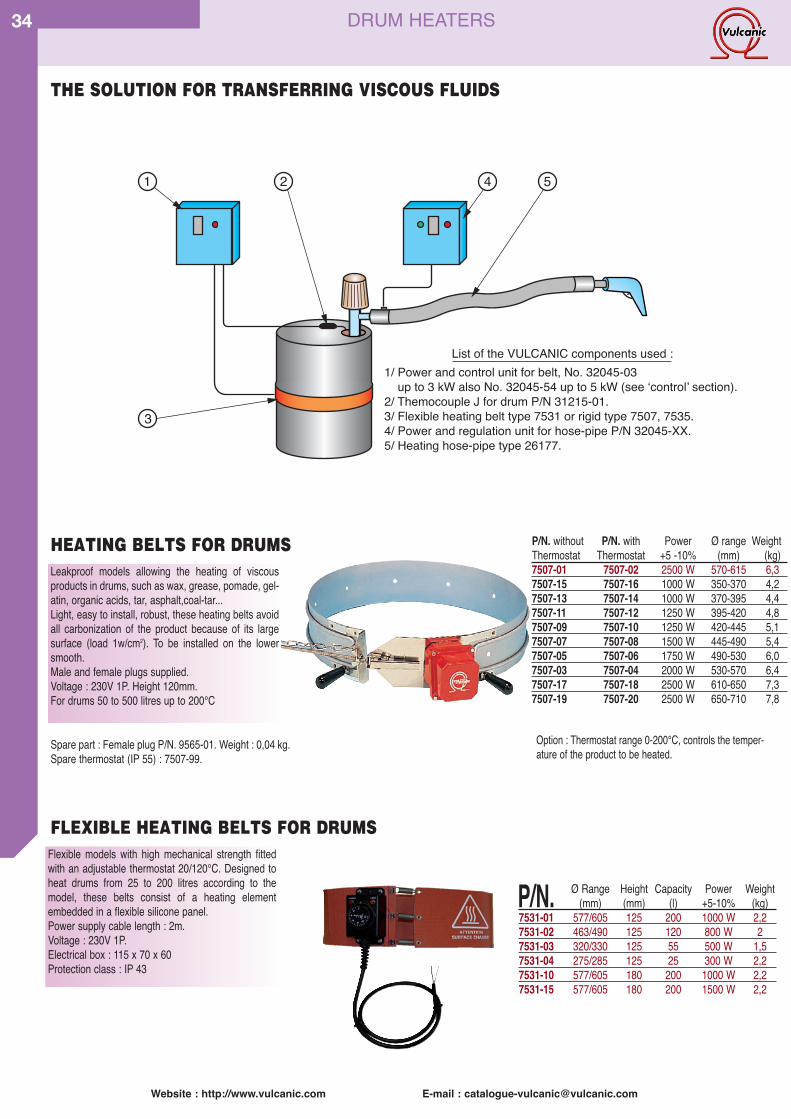
34
Spare part : Female plug P/N. 9565-01. Weight : 0,04 kg.Spare thermostat (IP 55) : 7507-99.
Option : Thermostat range 0-200°C, controls the temper-ature of the product to be heated.
P/N. without P/N. with Power Ø range WeightThermostat Thermostat +5 -10% (mm) (kg)7507-01 7507-02 2500 W 570-615 6,37507-15 7507-16 1000 W 350-370 4,27507-13 7507-14 1000 W 370-395 4,47507-11 7507-12 1250 W 395-420 4,87507-09 7507-10 1250 W 420-445 5,17507-07 7507-08 1500 W 445-490 5,47507-05 7507-06 1750 W 490-530 6,07507-03 7507-04 2000 W 530-570 6,47507-17 7507-18 2500 W 610-650 7,37507-19 7507-20 2500 W 650-710 7,8
P/N. Ø Range Height Capacity Power Weight(mm) (mm) (l) +5-10% (kg)
7531-01 577/605 125 200 1000 W 2,27531-02 463/490 125 120 800 W 27531-03 320/330 125 55 500 W 1,57531-04 275/285 125 25 300 W 2,27531-10 577/605 180 200 1000 W 2,27531-15 577/605 180 200 1500 W 2,2
Leakproof models allowing the heating of viscousproducts in drums, such as wax, grease, pomade, gel-atin, organic acids, tar, asphalt,coal-tar...Light, easy to install, robust, these heating belts avoidall carbonization of the product because of its largesurface (load 1w/cm2). To be installed on the lowersmooth.Male and female plugs supplied.Voltage : 230V 1P. Height 120mm. For drums 50 to 500 litres up to 200°C
HEATING BELTS FOR DRUMS
Flexible models with high mechanical strength fittedwith an adjustable thermostat 20/120°C. Designed toheat drums from 25 to 200 litres according to themodel, these belts consist of a heating elementembedded in a flexible silicone panel.Power supply cable length : 2m. Voltage : 230V 1P. Electrical box : 115 x 70 x 60 Protection class : IP 43
FLEXIBLE HEATING BELTS FOR DRUMS
DRUM HEATERS
Website : http://www.vulcanic.com E-mail : [email protected]
THE SOLUTION FOR TRANSFERRING VISCOUS FLUIDS
1/ Power and control unit for belt, No. 32045-03 up to 3 kW also No. 32045-54 up to 5 kW (see ʻcontrolʼ section).2/ Themocouple J for drum P/N 31215-01.3/ Flexible heating belt type 7531 or rigid type 7507, 7535.4/ Power and regulation unit for hose-pipe P/N 32045-XX.5/ Heating hose-pipe type 26177.
List of the VULCANIC components used :
1 2
3
4 5
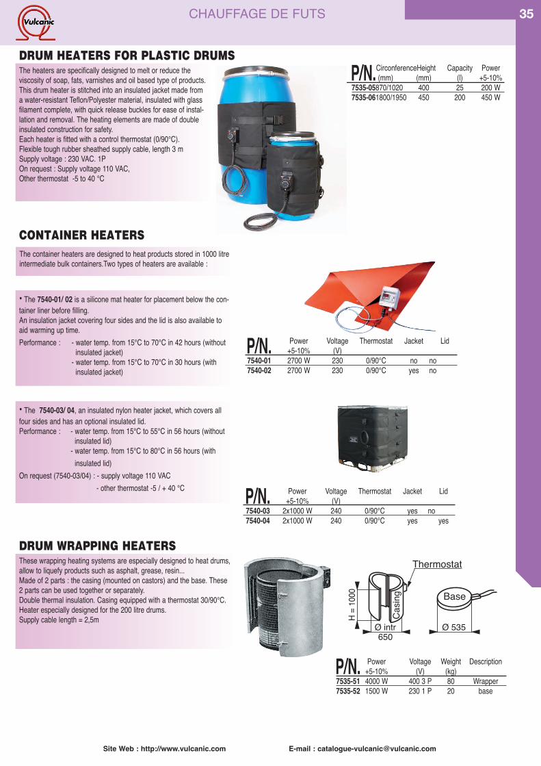
P/N.CirconferenceHeight Capacity Power(mm) (mm) (l) +5-10%
7535-05870/1020 400 25 200 W7535-061800/1950 450 200 450 W
P/N. Power Voltage Weight Description+5-10% (V) (kg)
7535-51 4000 W 400 3 P 80 Wrapper7535-52 1500 W 230 1 P 20 base
P/N. Power Voltage Thermostat Jacket Lid+5-10% (V)
7540-03 2x1000 W 240 0/90°C yes no7540-04 2x1000 W 240 0/90°C yes yes
Site Web : http://www.vulcanic.com E-mail : [email protected]
35
Ø intr Ø 535650
H = 1
000 Base
Casin
g
Thermostat
The heaters are specifically designed to melt or reduce the viscosity of soap, fats, varnishes and oil based type of products.This drum heater is stitched into an insulated jacket made froma water-resistant Teflon/Polyester material, insulated with glassfilament complete, with quick release buckles for ease of instal-lation and removal. The heating elements are made of doubleinsulated construction for safety.Each heater is fitted with a control thermostat (0/90°C).Flexible tough rubber sheathed supply cable, length 3 mSupply voltage : 230 VAC. 1POn request : Supply voltage 110 VAC, Other thermostat -5 to 40 °C
DRUM HEATERS FOR PLASTIC DRUMS
CONTAINER HEATERS
These wrapping heating systems are especially designed to heat drums,allow to liquefy products such as asphalt, grease, resin...Made of 2 parts : the casing (mounted on castors) and the base. These2 parts can be used together or separately.Double thermal insulation. Casing equipped with a thermostat 30/90°C.Heater especially designed for the 200 litre drums.Supply cable length = 2,5m
• The 7540-01/ 02 is a silicone mat heater for placement below the con-tainer liner before filling.An insulation jacket covering four sides and the lid is also available toaid warming up time.Performance : - water temp. from 15°C to 70°C in 42 hours (without
insulated jacket)- water temp. from 15°C to 70°C in 30 hours (with
insulated jacket)
DRUM WRAPPING HEATERS
CHAUFFAGE DE FUTS
• The 7540-03/ 04, an insulated nylon heater jacket, which covers allfour sides and has an optional insulated lid.Performance : - water temp. from 15°C to 55°C in 56 hours (without
insulated lid)- water temp. from 15°C to 80°C in 56 hours (with
insulated lid)On request (7540-03/04) : - supply voltage 110 VAC
- other thermostat -5 / + 40 °C
The container heaters are designed to heat products stored in 1000 litreintermediate bulk containers.Two types of heaters are available :
P/N. Power Voltage Thermostat Jacket Lid+5-10% (V)
7540-01 2700 W 230 0/90°C no no7540-02 2700 W 230 0/90°C yes no7540-03
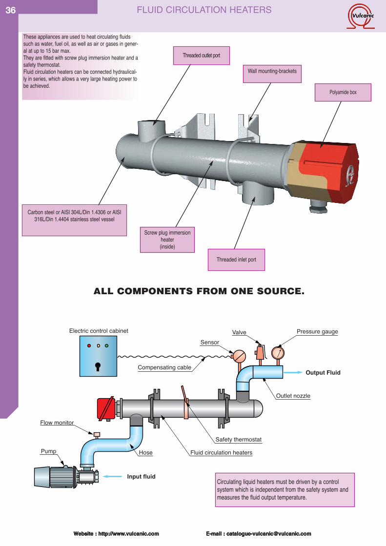
Website : http://www.vulcanic.com E-mail : [email protected]
36
Website : http://www.vulcanic.com E-mail : [email protected] : http://www.vulcanic.com E-mail : [email protected] : http://www.vulcanic.com E-mail : [email protected]
These appliances are used to heat circulating fluidssuch as water, fuel oil, as well as air or gases in gener-al at up to 15 bar max.They are fitted with screw plug immersion heater and asafety thermostat.Fluid circulation heaters can be connected hydraulical-ly in series, which allows a very large heating power tobe achieved.
Screw plug immersionheater(inside)
Carbon steel or AISI 304L/Din 1.4306 or AISI316L/Din 1.4404 stainless steel vessel
Threaded inlet port
Threaded outlet port
Wall mounting-brackets
Polyamide box
Electric control cabinet
Pump
Flow monitor
Hose
Input fluid
Output Fluid
Fluid circulation heaters
Compensating cable
Outlet nozzle
SensorValve Pressure gauge
Safety thermostat
ALL COMPONENTS FROM ONE SOURCE.
Circulating liquid heaters must be driven by a control system which is independent from the safety system andmeasures the fluid output temperature.
FLUID CIRCULATION HEATERS
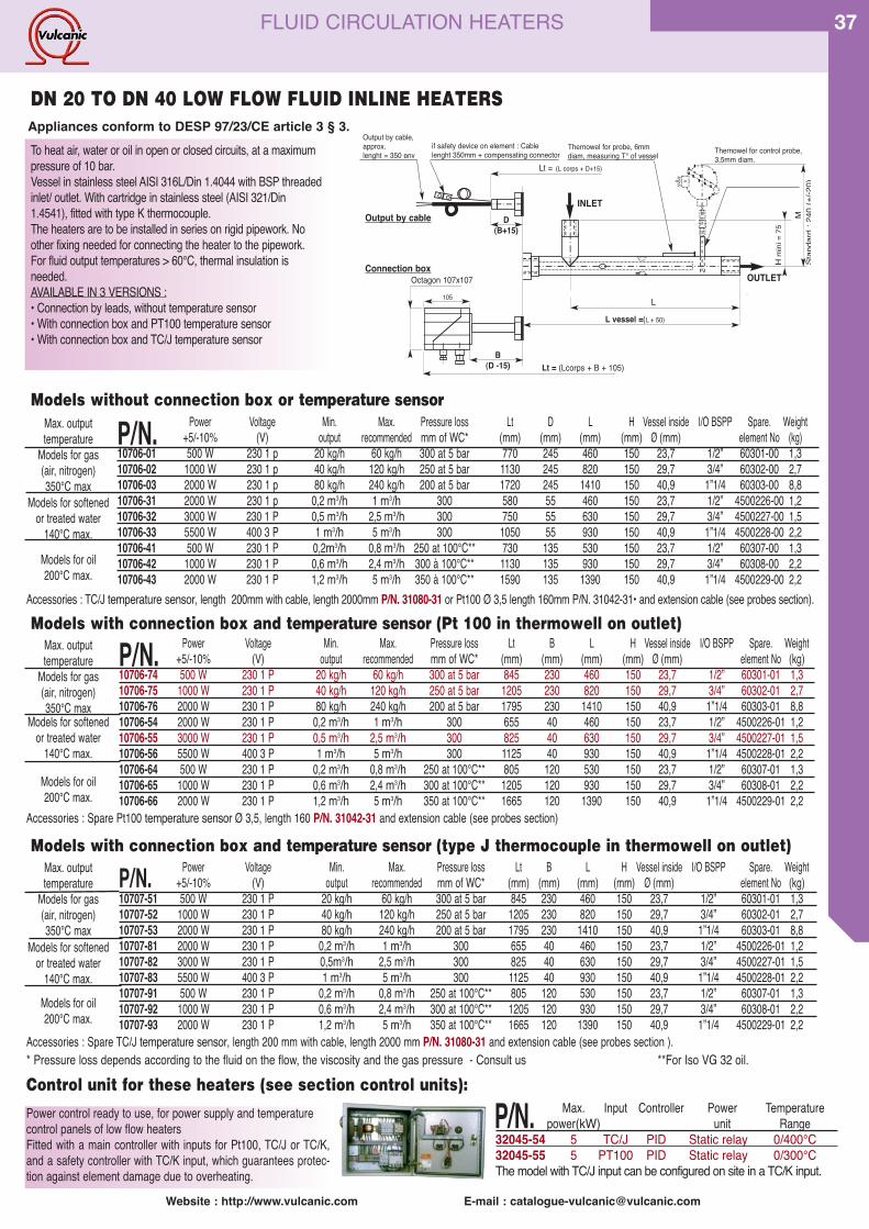
Website : http://www.vulcanic.com E-mail : [email protected]
37
To heat air, water or oil in open or closed circuits, at a maximumpressure of 10 bar.Vessel in stainless steel AISI 316L/Din 1.4044 with BSP threadedinlet/ outlet. With cartridge in stainless steel (AISI 321/Din1.4541), fitted with type K thermocouple. The heaters are to be installed in series on rigid pipework. Noother fixing needed for connecting the heater to the pipework.For fluid output temperatures > 60°C, thermal insulation is needed.AVAILABLE IN 3 VERSIONS :• Connection by leads, without temperature sensor• With connection box and PT100 temperature sensor• With connection box and TC/J temperature sensor
Max. outputtemperature
Models for gas(air, nitrogen)350°C max
Models for softenedor treated water
140°C max.Models for oil200°C max.
Control unit for these heaters (see section control units):
P/N. Power Voltage Min. Max. Pressure loss Lt D L H Vessel inside I/O BSPP Spare. Weight+5/-10% (V) output recommended mm of WC* (mm) (mm) (mm) (mm) Ø (mm) element No (kg)
10706-01 500 W 230 1 p 20 kg/h 60 kg/h 300 at 5 bar 770 245 460 150 23,7 1/2” 60301-00 1,310706-02 1000 W 230 1 p 40 kg/h 120 kg/h 250 at 5 bar 1130 245 820 150 29,7 3/4” 60302-00 2,710706-03 2000 W 230 1 p 80 kg/h 240 kg/h 200 at 5 bar 1720 245 1410 150 40,9 1”1/4 60303-00 8,810706-31 2000 W 230 1 p 0,2 m3/h 1 m3/h 300 580 55 460 150 23,7 1/2” 4500226-00 1,210706-32 3000 W 230 1 P 0,5 m3/h 2,5 m3/h 300 750 55 630 150 29,7 3/4” 4500227-00 1,510706-33 5500 W 400 3 P 1 m3/h 5 m3/h 300 1050 55 930 150 40,9 1”1/4 4500228-00 2,210706-41 500 W 230 1 P 0,2m3/h 0,8 m3/h 250 at 100°C** 730 135 530 150 23,7 1/2” 60307-00 1,310706-42 1000 W 230 1 P 0,6 m3/h 2,4 m3/h 300 à 100°C** 1130 135 930 150 29,7 3/4” 60308-00 2,210706-43 2000 W 230 1 P 1,2 m3/h 5 m3/h 350 à 100°C** 1590 135 1390 150 40,9 1”1/4 4500229-00 2,2
Models for oil200°C max.
P/N. Power Voltage Min. Max. Pressure loss Lt B L H Vessel inside I/O BSPP Spare. Weight+5/-10% (V) output recommended mm of WC* (mm) (mm) (mm) (mm) Ø (mm) element No (kg)
10706-74 500 W 230 1 P 20 kg/h 60 kg/h 300 at 5 bar 845 230 460 150 23,7 1/2” 60301-01 1,310706-75 1000 W 230 1 P 40 kg/h 120 kg/h 250 at 5 bar 1205 230 820 150 29,7 3/4” 60302-01 2,710706-76 2000 W 230 1 P 80 kg/h 240 kg/h 200 at 5 bar 1795 230 1410 150 40,9 1”1/4 60303-01 8,810706-54 2000 W 230 1 P 0,2 m3/h 1 m3/h 300 655 40 460 150 23,7 1/2” 4500226-01 1,210706-55 3000 W 230 1 P 0,5 m3/h 2,5 m3/h 300 825 40 630 150 29,7 3/4” 4500227-01 1,510706-56 5500 W 400 3 P 1 m3/h 5 m3/h 300 1125 40 930 150 40,9 1”1/4 4500228-01 2,210706-64 500 W 230 1 P 0,2 m3/h 0,8 m3/h 250 at 100°C** 805 120 530 150 23,7 1/2” 60307-01 1,310706-65 1000 W 230 1 P 0,6 m3/h 2,4 m3/h 300 at 100°C** 1205 120 930 150 29,7 3/4” 60308-01 2,210706-66 2000 W 230 1 P 1,2 m3/h 5 m3/h 350 at 100°C** 1665 120 1390 150 40,9 1”1/4 4500229-01 2,2
Max. outputtemperature
Models for gas(air, nitrogen)350°C max
Models for softenedor treated water
140°C max.Models for oil200°C max.
P/N. Power Voltage Min. Max. Pressure loss Lt B L H Vessel inside I/O BSPP Spare. Weight+5/-10% (V) output recommended mm of WC* (mm) (mm) (mm) (mm) Ø (mm) element No (kg)
10707-51 500 W 230 1 P 20 kg/h 60 kg/h 300 at 5 bar 845 230 460 150 23,7 1/2” 60301-01 1,310707-52 1000 W 230 1 P 40 kg/h 120 kg/h 250 at 5 bar 1205 230 820 150 29,7 3/4” 60302-01 2,710707-53 2000 W 230 1 P 80 kg/h 240 kg/h 200 at 5 bar 1795 230 1410 150 40,9 1”1/4 60303-01 8,810707-81 2000 W 230 1 P 0,2 m3/h 1 m3/h 300 655 40 460 150 23,7 1/2” 4500226-01 1,210707-82 3000 W 230 1 P 0,5m3/h 2,5 m3/h 300 825 40 630 150 29,7 3/4” 4500227-01 1,510707-83 5500 W 400 3 P 1 m3/h 5 m3/h 300 1125 40 930 150 40,9 1”1/4 4500228-01 2,210707-91 500 W 230 1 P 0,2 m3/h 0,8 m3/h 250 at 100°C** 805 120 530 150 23,7 1/2” 60307-01 1,310707-92 1000 W 230 1 P 0,6 m3/h 2,4 m3/h 300 at 100°C** 1205 120 930 150 29,7 3/4” 60308-01 2,210707-93 2000 W 230 1 P 1,2 m3/h 5 m3/h 350 at 100°C** 1665 120 1390 150 40,9 1”1/4 4500229-01 2,2
Models with connection box and temperature sensor (Pt 100 in thermowell on outlet)
Models with connection box and temperature sensor (type J thermocouple in thermowell on outlet)
* Pressure loss depends according to the fluid on the flow, the viscosity and the gas pressure - Consult us **For Iso VG 32 oil.
Accessories : TC/J temperature sensor, length 200mm with cable, length 2000mm P/N. 31080-31 or Pt100 Ø 3,5 length 160mm P/N. 31042-31• and extension cable (see probes section).
Accessories : Spare Pt100 temperature sensor Ø 3,5, length 160 P/N. 31042-31 and extension cable (see probes section)
Accessories : Spare TC/J temperature sensor, length 200 mm with cable, length 2000 mm P/N. 31080-31 and extension cable (see probes section ).
Power control ready to use, for power supply and temperaturecontrol panels of low flow heatersFitted with a main controller with inputs for Pt100, TC/J or TC/K,and a safety controller with TC/K input, which guarantees protec-tion against element damage due to overheating.
P/N. Max. Input Controller Power Temperaturepower(kW) unit Range
32045-54 5 TC/J PID Static relay 0/400°C32045-55 5 PT100 PID Static relay 0/300°CThe model with TC/J input can be configured on site in a TC/K input.
Appliances conform to DESP 97/23/CE article 3 § 3.DN 20 TO DN 40 LOW FLOW FLUID INLINE HEATERS
if safety device on element : Cablelenght 350mm + compensating connector
Output by cable,approx.lenght = 350 env. Thernowel for control probe,
3,5mm diam.Thernowel for probe, 6mm diam, measuring T° of vessel
Output by cable
Connection box
D(B+15)
MSt
anda
rd :
240
(+/-2
0)
Hm
ini =
75
OUTLET
INLET
105 LL vessel = (L + 50)
Lt = (Lcorps + B + 105)
Octagon 107x107
Lt = (L corps + D+15)
B(D -15)
Max. outputtemperature
Models for gas(air, nitrogen)350°C max
Models for softenedor treated water
140°C max.
Models without connection box or temperature sensor
FLUID CIRCULATION HEATERS
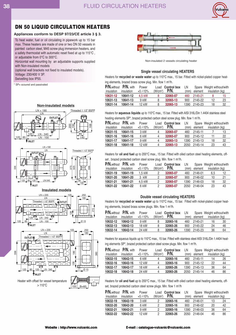
Website : http://www.vulcanic.com E-mail : [email protected]
38
Website : http://www.vulcanic.com E-mail : [email protected] : http://www.vulcanic.com E-mail : [email protected] : http://www.vulcanic.com E-mail : [email protected]
LN - 340¯ 15
LN 180
128 21
5
LN + 235
Threaded 1 1/2" BSPP
105 250
LN - 100120 85120
OUTLET
INLET
OUTLETLN
LN + 235
Threaded 1 1/2" BSPP
105
LN - 340120 12085
180
380
250
¯ 15
INLET
336
186
128
Non-insulated models
150
200
85120 LN - 340
LN
140LN - 10085120
LN + 190 Threaded 1 1/2" BSPP
168
OUTLET
INLET
325
336
375
120 85 120 LN-340
LN +190
140
LN Threaded 1 1/2" BSPP
85
OUTLET
INLET
336
Insulated models
B=60105
Heater with offset for vessel temperature> 110°C
Single vessel circulating HEATERSHeaters for recycled or waste water up to 110°C max., 15 bar. Fitted with nickel-plated copper heat-ing elements, brazed brass screw plug. Min. flow 1 m3/h.P/N.without P/N. with Power Load Control box LN Spare Weight without/withinsulation insulation +5 /-10% (W/cm2) P/N. (mm) element insulation (kg)
10631-12 10641-12 4,5 kW 8 32065-07 460 2145-21 8 1510631-13 10641-13 9 kW 8 32065-13 900 2145-22 12 2310631-14 10641-14 12 kW 8 32065-13 1390 2145-23 18 32
Heaters for aqueous liquids up to 110°C max., 15 bar. Fitted with AISI 316L/Din 1.4404 stainless steelheating elements SP*, brazed protected carbon steel screw plug. Min. flow 1 m3/h.P/N.without P/N. with Power Load Control box LN Spare Weight without/withinsulation insulation +5 /-10% (W/cm2) P/N. (mm) element insulation (kg)
10631-15 10641-15 3 kW 4 32065-07 460 2145-11 7 1310631-16 10641-16 6 kW 4 32065-07 900 2145-12 11 2210631-17 10641-17 9 kW 4 32065-13 1390 2145-13 18 3210631-18 10641-18 12 kW 4 32065-13 2050 2145-14 23 43
Heaters for oil and fuel up to 200°C max., 15 bar. Fitted with oiled carbon steel heating elements, off-set , brazed protected carbon steel screw plug. Min. flow 1 m3/h.P/N.without P/N. with Power Load Control box LN Spare Weight without/withinsulation insulation +5 /-10% (W/cm2) P/N. (mm) element insulation (kg)
10631-19 10641-19 1,5 kW 2 32065-07 460 2146-01 6,5 1210631-20 10641-20 3 kW 2 32065-07 900 2146-02 10 2110631-21 10641-21 4,5 kW 2 32065-07 1390 2146-03 18 3210631-22 10641-22 6 kW 2 32065-07 2050 2146-04 23 43
Double vessel circulating HEATERS Heaters for recycled or waste water up to 110°C max., 15 bar. Fitted with nickel-plated copper heat-ing elements, brazed brass screw plugs. Min. flow 1 m3/h.P/N.without P/N. with Power Load Control box LN Spare Weight without/withinsulation insulation +5 /-10% (W/cm2) P/N. (mm) element insulation (kg)
10632-12 10642-12 9 kW 8 32065-16 460 2145-21 16 3010632-13 10642-13 18 kW 8 32065-26 900 2145-22 24 4610632-14 10642-14 24 kW 8 32065-26 1390 2145-23 36 64
Heaters for aqueous liquids up to 110°C max., 15 bar. Fitted with stainless steel AISI 316L/Din 1.4404 heat-ing elements SP*, brazed protected carbon steel screw plugs. Min. flow 1 m3/h.P/N.without P/N. with Power Load Control box LN Spare Weight without/withinsulation insulation +5 /-10% (W/cm2) P/N. (mm) element insulation (kg)
10632-15 10642-15 6 kW 4 32065-16 460 2145-11 14 2610632-16 10642-16 12 kW 4 32065-16 900 2145-12 22 4410632-17 10642-17 18 kW 4 32065-26 1390 2145-13 36 6410632-18 10642-18 24 kW 4 32065-26 2050 2145-14 46 86
Heaters for oil and fuel up to 200°C max., 15 bar. Fitted with oiled carbon steel heating elements, off-set, brazed protected carbon steel screw plugs. Min. flow 1 m3/hP/N.without P/N. with Power Load Control box LN Spare Weight without/withinsulation insulation +5 /-10% (W/cm2) P/N. (mm) element insulation (kg)
10632-19 10642-19 3 kW 2 32065-16 460 2146-01 13 2410632-20 10642-20 6 kW 2 32065-16 900 2146-02 20 4210632-21 10642-21 9 kW 2 32065-16 1390 2146-03 36 6410632-22 10642-22 12 kW 2 32065-26 2050 2146-04 46 86
To heat water, fuel or oil circulating in pipework up to 15 barmax. These heaters are made of one or two DN 50 vessels inpainted carbon steel, M45 screw plug immersion heaters, anda safety thermostat with automatic reset fixed at up to 115°C ,or adjustable from 0°C to 300°C.Horizontal wall mounting by an adjustable supports suppliedwith Non-insulated models(optional wall brackets not fixed to insulated models).Voltage: 230/400 V 3P.Swivelling box IP55.
Appliances conform to DESP 97/23/CE article 3 § 3.DN 50 LIQUID CIRCULATION HEATERS
Non-insulated 2 vessels circulating heater
* SP= scoured and passivated
FLUID CIRCULATION HEATERS
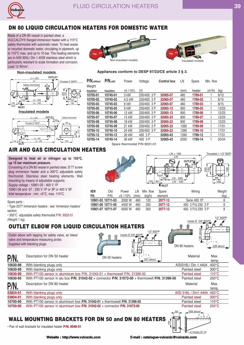
Website : http://www.vulcanic.com E-mail : [email protected]
39
Website : http://www.vulcanic.com E-mail : [email protected] : http://www.vulcanic.com E-mail : [email protected] : http://www.vulcanic.com E-mail : [email protected] : http://www.vulcanic.com E-mail : [email protected]
Made of a DN 80 vessel in painted steel, aVULCALOY® flanged immersion heater with a 115°Csafety thermostat with automatic reset. To heat wasteor recycled domestic water, circulating in pipework, upto 110°C max. and up to 10 bar. The heating elementsare in AISI 904L/ Din 1.4539 stainless steel which isparticularly resistant to scale formation and corrosion. Load 12 W/cm2.
P/N.without P/N.with Power Voltage Control box LN Spare Min. flow WeightInsulation Insulation +5 /-10% (V) (mm) heater (m3/h) (kg)10705-01 10745-01 3 kW 230/400 3 P 32065-07 460 1789-01 1 8/1510705-02 10745-02 4,5 kW 230/400 3 P 32065-07 460 1789-02 1 8/1510705-03 10745-03 6 kW 230/400 3 P 32065-07 460 1789-03 1 8/1510705-05 10745-05 9 kW 230/400 3 P 32065-13 900 1789-05 1 12/2310705-06 10745-06 12 kW 230/400 3 P 32065-13 900 1789-06 1 12/2310705-07 10745-07 15 kW 230/400 3 P 32065-23 900 1789-07 1 12/2310705-08 10745-08 18 kW 230/400 3 P 32065-23 900 1789-08 1 12/2310705-09 10745-09 21 kW 230/400 3 P 32065-23 1390 1789-09 1 17/3110705-10 10745-10 24 kW 230/400 3 P 32065-23 1390 1789-10 1 17/3110705-12 10745-12 30 kW 400 3 P 32065-43 1390 1789-12 1 17/3110705-14 10745-14 36 kW 400 3 P 32065-43 2050 1789-14 1 20/34
DN 80 LIQUID CIRCULATION HEATERS FOR DOMESTIC WATER
Ln - 340250
15
Safety thermostat
120
180
Ln - 100
Ln
128 21
5
Ln + 245105
145 95
Threated 2" BSPP
OUTLET
INLET
Ln - 340 100155
Safety thermostat 14
120Ln - 100
Ln
150
200
Ln + 200
145maxi
95
168
Threated 2" BSPP
INLET
OUTLETNon-insulated models
Insulated models
126
abou
t
226 about
1/2" BSPPInside Ø 3/8" BSPP
Outlet elbow with tapping for safety valve, air bleedvalve and temperature measuring probe.Supplied with blanking plugs.
107
abou
t
207 about
1/2" BSPPInside ¯ 3/8" BSPP
DN 50 heaters
DN 80 heaters
Designed to heat air or nitrogen up to 150°C, up 15 bar maximum pressure.Consisting of a DN 80 vessel in painted steel, Ø 77 screwplug immersion heater and a 300°C adjustable safetythermostat. Stainless steel heating elements. Wallmounting by means of adjustable supports.Supply voltage : 10901-03 : 400 V 1P10901-06 and -07 : 230 V 1P or 3P or 400 V 3P. Inlet temperature : min. +5°C, max. 110°C.
AIR AND GAS CIRCULATION HEATERS
NEW Old Power LN Min. flow Spare Wiring WeightP/N. P/N. +5 /-10% (mm) (kg/h) element (kg)10901-03 10711-03 2000 W 460 120 2077-13 Serie 400 1P 810901-06 10711-06 4500 W 460 350 2077-12 400 3 P/∆ 230 3 P 810901-07 10711-07 6000 W 460 350 2077-13 400 3 P/∆ 230 3 P 8
Spare parts :• Type 2077 immersion heaters : see ʻimmersion heatersʼsection.• 300°C adjustable safety thermostat P/N. 9032-01(Weight 1 kg).
OUTLET ELBOW FOR LIQUID CIRCULATION HEATERS
P/N. Description for DN 50 heater . Material Max. temp
10630-98 With blanking plugs only AISI316L/ Din 1.4404 450°C10630-99 With blanking plugs only Painted steel 300°C10630-90 With PT100 sensor in aluminium box P/N. 31042-01 + thermowell P/N. 31396-50 Painted steel 110°C10630-95 With PT100 sensor in alu box P/N. 31042-02 + connector P/N. 31672-00 + thermowell P/N. 31396-50 Painted steel 250°C
P/N. Description for DN 80 heater Material Max.temp.
53824-01 With blanking plugs only AISI 316L / Din1.4404 450°C53804-01 With blanking plugs only Painted steel 300°C10700-90 With PT100 sensor in aluminium box P/N. 31042-01 + thermowell P/N. 31396-50 Painted steel 110°C10700-95 With PT100 sensor in aluminium box P/N. 31042-02 + connector P/N. 31672-00 Painted steel 250°C
100
60 358 about
4 Holes Ø 10• Pair of wall brackets for insulated heater P/N. 6048-01WALL MOUNTING BRACKETS FOR DN 50 and DN 80 HEATERS
Non-insulated models Insulated models
150
200
85120 LN - 340
LN
140LN - 10085120
LN + 190 Threaded 1 1/2" BSPP
168
OUTLET
INLET
Appliances conform to DESP 97/23/CE article 3 § 3.
Spare thermostat P/N 9031-01
FLUID CIRCULATION HEATERS
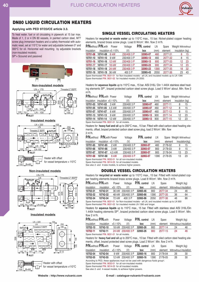
Website : http://www.vulcanic.com E-mail : [email protected]
40 FLUID CIRCULATION HEATERS
To heat water, fuel or oil circulating in pipework at 15 bar max.Made of 1, 2 or 4 DN 80 vessels, in painted carbon steel, M77screw plug immersion heaters and a safety thermostat with auto-matic reset, set at 115°C for water and adjustable between 0° and300°C for oil. Horizontal wall mounting by adjustable brackets(non-insulated models).SP*= Scoured and passived
LN - 340 ¯ 15
LN180
128 21
5
LN + 220
Threaded 2" BSPP
105250
LN-100120 70120
OUTLET
INLET
Insulated models
Non-insulated models
150
200
100120 LN - 340
LN
155LN - 10070120
LN + 170 Threaded 2" BSPP
168
OUTLET
INLET
326
336
10
375
120 70 120 LN-340
LN+170
155
LN Threaded 2" BSPP
100
OUTLET
INLET
+ -
OUTLETLN
LN + 220
Threaded 2" BSPP
105
LN - 340120 12070
180
380
250
¯ 15INLET
128
168336
B=60105
Heater with offsetfor vessel temperature > 110°C
Non-insulated models
Insulated models
Heaters for recycled or waste water up to 110°C max., 15 bar. Fitted with nickel-plated cop-per heating elements brazed brass screw plugs. Load 8 W/cm2. Min. flow 2 m3/h.P/N.without P/N.with Power Voltage P/N. control LN Spare Weight (kg)insulation insulation +5/ -10% (V) box (mm) element With/without insulation10702-31 10742-31 36 kW 230/400 3 P 32065-46 900 2077-34 24 4610702-32 10742-32 48 kW 230/400 3 P 32065-66 1390 2077-35 36 6410702-34 10742-34 72 kW 400 3 P 32065-96 2050 2077-36 46 86Spare thermostat P/N. 9031-01 for Non-insulated models - all LN, and insulated models up to LN 900Spare thermostat P/N. 9031-02 for insulated models LN 1390 and longer.Heaters for aqueous liquids up to 110°C max., 15 bar. Fitted with stainless steel AISI 316L/Din1.4404 heating elements SP*, brazed protected carbon steel screw plugs. Load 5 W/cm2. Min.flow 2 m3/h.P/N.without P/N.with Power Voltage P/N. control LN Spare Weight (kg)insulation insulation +5 /-10% (V) box (mm) element With/without insulation10702-10 10742-10 18 kW 230/400 3 P 32065-26 900 2077-14 24 4610702-11 10742-11 24 kW 230/400 3 P 32065-26 900 2077-15 24 46Spare thermostat P/N. 9031-01 for all models.Heaters for heavy fuel and oil up to 200°C max., 15 bar. Fitted with oiled carbon steel heating ele-ments, offset, brazed protected steel screw plugs. Load 2 W/cm2. Min. flow 2 m3/h.P/N.without P/N.with Power Voltage P/N. control LN Spare Weight (kg)insulation insulation +5 /-10% (V) box (mm) element With/without insulation10702-54 10742-54 9 kW 230/400 3 P 32065-16 900 2178-04 26 3010702-55 10742-55 12 kW 230/400 3 P 32065-16 1390 2178-05 26 30According to PED, these appliances must not be used with dangerous fluids group1.Spare thermostat P/N. 9032-01 for all non-insulated modelsSpare thermostat P/N. 9014-03 for all insulated models.See also 2- and 4-vessel models, to achieve higher powers.
Heaters for recycled or waste water up to 110°C max., 15 bar. Nickel-plated copper heatingelements, brazed brass screw plugs. Load 8 W/cm2. Min. flow 2 m3/h.P/Nwithout P/N.with Power Voltage P/N. control LN Spare Weight With/withoutinsulation insulation +5 /-10% (V) box (mm) element insulation (kg)10701-08 10741-08 6 kW 230/400 3 P 32065-07 460 2077-31 8 1510701-10 10741-10 9 kW 230/400 3 P 32065-13 460 2077-32 8 1510701-16 10741-16 12 kW 230/400 3 P 32065-13 900 2077-33 12 2310701-17 10741-17 18 kW 230/400 3 P 32065-23 900 2077-34 12 2310701-18 10741-18 24 kW 230/400 3 P 32065-23 1390 2077-35 18 3210701-19 10741-19 36 kW 400 3 P 32065-43 2050 2077-36 23 43Spare thermostat P/N. 9031-01 for Non-insulated models - all LN, and insulated models up to LN 1390Spare thermostat P/N. 9031-02 for insulated models LN 2050.
Heaters for aqueous liquids up to 110°C max., 15 bar. AISI 316L/ Din 1.4404 stainless steel heat-ing elements SP*, brazed protected carbon steel screw plugs. Load 5 W/cm2 about. Min. flow 2m3/h.P/Nwithout P/N.with Power Voltage P/N. control LN Spare Weight With/withoutinsulation insulation +5 /-10% (V) box (mm) element insulation (kg)10701-03 10741-03 3 kW 230/400 3 P 32065-07 460 2077-11 8 1510701-05 10741-05 4,5 kW 230/400 3 P 32065-07 460 2077-12 8 1510701-07 10741-07 6 kW 230/400 3 P 32065-07 460 2077-13 8 1510701-13 10741-13 9 kW 230/400 3 P 32065-13 900 2077-14 12 2310701-14 10741-14 12 kW 230/400 3 P 32065-13 900 2077-15 12 23Spare thermostat P/N. 9031-01 for all models.Heaters for heavy fuel and oil up to 200°C max., 15 bar. Fitted with oiled carbon steel heating ele-ments, offset, brazed protected carbon steel screw plug, load 2 W/cm2. Min. flow2 m3/h.P/N.without P/N.with Power Voltage P/N. control LN Spare Weight With/withoutinsulation insulation +5 /-10% (V) box (mm) element insulation(kg)10701-65 10741-65 2 kW 230/400 3 P 32065-07 460 2178-02 9 1510701-66 10741-66 3 kW 230/400 3 P 32065-07 900 2178-03 9 1510701-67 10741-67 4,5 kW 230/400 3 P 32065-07 900 2178-04 13 2310701-68 10741-68 6 kW 230/400 3 P 32065-07 1390 2178-05 13 23Spare thermostat P/N. 9032-01 for all non-insulated modelsSpare thermostat P/N. 9014-03 for all insulated models.See also 2- and 4-tube models, to achieve higher powers.
B=60105
Heater with offsetfor vessel temperature >110°C
DOUBLE VESSEL CIRCULATION HEATERS
Applying with PED 97/23/CE article 3.3.SINGLE VESSEL CIRCULATING HEATERS
DN80 LIQUID CIRCULATION HEATERS
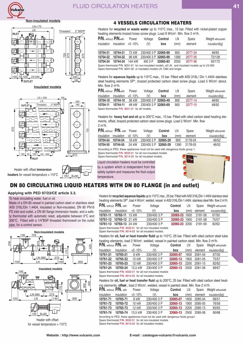
Website : http://www.vulcanic.com E-mail : [email protected]
41FLUID CIRCULATION HEATERS
OUTLETLN
LN + 220
Threaded 1 1/2" BSPP
105
LN - 340120 12070
180
720
250
15INLET
O
672
675
672
725
120 70 120 LN-340
LN+170
160
LN Manchons taraud�s 2" gaz
100
INLET
OUTLET
Threaded 1 1/2" BSPP Heaters for recycled or waste water up to 110°C max., 15 bar. Fitted with nickel-plated copperheating elements brazed brass screw plugs. Load 8 W/cm2. Min. flow 2 m3/h.P/N. without P/N.with Power Voltage Control LN Spare Weight without/withinsulation insulation +5 -10% (V) box (mm) element insulation(kg)
10704-31 10744-31 72 kW 230/400 3 P 32065-99 900 2077-34 48/9510704-32 10744-32 96 kW 230/400 3 P 32065-99 1390 2077-35 72/12810704-34 10744-34 144 kW 400 3 P 32065-83 2050 2077-36 92/172Spare thermostat P/N. 9031-01 for non-insulated models, all LN, and insulated models up to LN 900Spare thermostat P/N. 9031-02 or insulated models LN 1390 and longer.
Heaters for aqueous liquids up to 110°C max., 15 bar. Fitted with AISI 316L/ Din 1.4404 stainlesssteel heating elements SP*, brazed protected carbon steel screw plugs. Load 5 W/cm2 about.Min. flow 2 m3/h.P/N. without P/N.with Power Voltage Control LN Spare Weight without/withinsulation insulation +5 -10% (V) box (mm) element insulation(kg)10704-10 10744-10 36 kW 230/400 3 P 32065-49 900 2077-14 48/9210704-11 10744-11 48 kW 230/400 3 P 32065-69 900 2077-15 48/92Spare thermostat P/N. 9031-01 for all models.
Heaters for heavy fuel and oil up to 200°C max., 15 bar. Fitted with oiled carbon steel heating ele-ments, offset, brazed protected carbon steel screw plugs. Load 2 W/cm2. Min. flow2 m3/h.P/N. without P/N. with Power Voltage Control LN Spare Weight without/withinsulation insulation +5 -10% (V) box (mm) element insulation(kg)10704-54 10744-54 18 kW 230/400 3 P 32065-29 900 2178-04 46/5210704-55 10744-55 24 kW 230/400 3 P 32065-29 1390 2178-05 46/52According to PED, these appliances must not be used with dangerous fluids group 1.Spare thermostat P/N. 9032-01 for all non-insulated modelsSpare thermostat P/N. 9014-03 for all insulated models.
4 VESSELS CIRCULATION HEATERS
136
258
LN120 140275
300
429
170
LN-390
704
215
140
LN120 140275
300
429
300
170
LN-390
Insulated models
Non-insulated models
To heat circulating water, fuel or oil.Made of a DN 80 vessel in painted carbon steel or stainless steelAISI 316L/Din 1.4404, insulated or Non-insulated, DN 80 PN16FS inlet and outlet, a DN 80 flange immersion heater, and a safe-ty thermostat with automatic reset, adjustable between 0°C and300°C. Fitted with a 1/4”BSP threaded thermowell on the outletpipe, for a control sensor.
DN 80 CIRCULATING LIQUID HEATERS WITH DN 80 FLANGE (in and outlet)
Heaters for recycled aqueous liquids up to 110°C max., 25 bar. Fitted with AISI 316L/Din 1.4404 stainless steelheating elements SP*, load 4 W/cm2, welded. vessel in AISI 316L/Din 1.4404. stainless steel Min. flow 2 m3/h.P/N. without P/N. with Power Voltage Control LN Spare Weight without/withinsulation insulation +5 -10% (V) box (mm) element insulation(kg)10761-11 10765-11 15 kW 230/400 3 P 32065-23 1600 2181-56 67/5010761-12 10765-12 21 kW 230/400 3 P 32065-23 1900 2181-58 75/5710761-13 10765-13 24 kW 230/400 3 P 32065-23 2200 2181-59 82/62Spare thermostat P/N. 9032-01 for all non-insulated modelsSpare thermostat P/N. 9014-03 for all insulated models.Heaters for oil, fuel or heat transfer fluid up to 110°C, 25 bar. Fitted with oiled carbon steel tubeheating elements, load 2 W/cm2, welded, vessel in painted carbon steel. Min. flow 2 m3/h.P/N. without P/N. with Power Voltage Control LN Spare Weight without/withinsulation insulation +5 -10% (V) box (mm) element insulation(kg)10761-21 10765-21 8 kW 230/400 3 P 32065-07 1600 2081-04 67/5010761-22 10765-22 10 kW 230/400 3 P 32065-13 1900 2081-05 75/5710761-23 10765-23 12 kW 230/400 3 P 32065-13 2200 2081-15 82/6210761-24 10765-24 13,5 kW 230/400 3 P 32065-13 2500 2081-06 89/67Spare thermostat P/N. 9032-01 for all non-insulated modelsSpare thermostat P/N. 9014-03 for all insulated models.Heaters for oil, fuel or heat transfer fluid up to 200°C, 25 bar. Fitted with oiled carbon steel heat-ing elements, offset , load 2 W/cm2, welded, vessel in painted steel. Min. flow 2 m3/h.P/N. without P/N. with Power Voltage Control LN Spare Weight without/withinsulation insulation +5 -10% (V) box (mm) element insulation(kg)10761-71 10765-71 8 kW 230/400 3 P 32065-07 1600 2085-04 68/5110761-72 10765-72 10 kW 230/400 3 P 32065-13 1900 2085-05 76/5810761-73 10765-73 12 kW 230/400 3 P 32065-13 2200 2085-15 83/6310761-74 10765-74 13,5 kW 230/400 3 P 32065-13 2500 2085-06 90/68According to PED, these appliances must not be used with dangerous fluids group1.Spare thermostat P/N. 9032-01 for all non-insulated modelsSpare thermostat P/N. 9014-03 for all insulated models.
Liquid circulation heaters must be controlledby a system which is independent from thesafety system and measures the fluid outputtemperature.
Non-insulated models
Insulated models
B=60105
Heater with offset immersion heaters for vessel temperature > 110°C
B=60105
Heater with offset for vessel temperature > 110°C
Applying with PED 97/23/CE article 3.3.
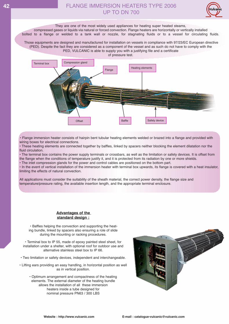
Website : http://www.vulcanic.com E-mail : [email protected]
42 FLANGE IMMERSION HEATERS TYPE 2006 UP TO DN 700
Advantages of the standard design :
• Baffles helping the convection and supporting the heat-ing bundle, linked by spacers also ensuring a role of slide
during the mounting or racking procedures.
• Terminal box to IP 55, made of epoxy painted steel sheet, for installation under a shelter, with optional roof for outdoor use and
alternative stainless steel box to IP 66.
• Two limitation or safety devices, independent and interchangeable.
• Lifting ears providing an easy handling, in horizontal position as wellas in vertical position.
• Optimum arrangement and compactness of the heating elements. The external diameter of the heating bundle
allows the installation of all these immersionheaters inside a tube designed for nominal pressure PN63 / 300 LBS
They are one of the most widely used appliances for heating super heated steams,compressed gases or liquids via natural or forced convection. Flange heaters are horizontally or vertically installed
bolted to a flange or welded to a tank wall or nozzle, for stagnating fluids or to a vessel for circulating fluids.
Those equipments are designed and manufactured for installation on vessels in compliance with 97/23/EC European directive(PED). Despite the fact they are considered as a component of the vessel and as such do not have to comply with the
PED, VULCANIC is able to supply you with a justifying file and a certificate of pressure test.
• Flange immersion heater consists of hairpin bent tubular heating elements welded or brazed into a flange and provided withwiring boxes for electrical connections.• These heating elements are connected together by baffles, linked by spacers neither blocking the element dilatation nor thefluid circulation.• The terminal box contains the power supply terminals or crossbars, as well as the limitation or safety devices. It is offset fromthe flange when the conditions of temperature justify it, and it is protected from its radiation by one or more shields.• The inlet compression glands for the power and control cables are positioned on the bottom part.• In the event of vertical installation of the immersion heater with terminal box upwards, its flange is covered with a heat insulator,limiting the effects of natural convection.
All applications must consider the suitability of the sheath material, the correct power density, the flange size andtemperature/pressure rating, the available insertion length, and the appropriate terminal enclosure.
Terminal box Compression gland
Offset
Flange
Baffle
Heating elements
Safety device
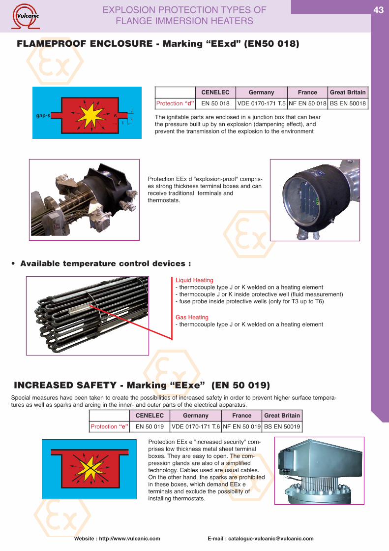
Website : http://www.vulcanic.com E-mail : [email protected]
43
FLAMEPROOF ENCLOSURE - Marking “EExd” (EN50 018)
The ignitable parts are enclosed in a junction box that can bearthe pressure built up by an explosion (dampening effect), andprevent the transmission of the explosion to the environment
300
gap-s sl
Protection EEx d "explosion-proof" compris-es strong thickness terminal boxes and canreceive traditional terminals and thermostats.
• Available temperature control devices :
INCREASED SAFETY - Marking “EExe” (EN 50 019)Special measures have been taken to create the possibilities of increased safety in order to prevent higher surface tempera-tures as well as sparks and arcing in the inner- and outer parts of the electrical apparatus.
Protection EEx e "increased security" com-prises low thickness metal sheet terminalboxes. They are easy to open. The com-pression glands are also of a simplifiedtechnology. Cables used are usual cables.On the other hand, the sparks are prohibitedin these boxes, which demand EEx e terminals and exclude the possibility of installing thermostats.
CENELEC Germany France Great BritainProtection “d” EN 50 018 VDE 0170-171 T.5 NF EN 50 018 BS EN 50018
Liquid Heating- thermocouple type J or K welded on a heating element- thermocouple J or K inside protective well (fluid measurement)- fuse probe inside protective wells (only for T3 up to T6)
Gas Heating- thermocouple type J or K welded on a heating element
CENELEC Germany France Great BritainProtection “e” EN 50 019 VDE 0170-171 T.6 NF EN 50 019 BS EN 50019
EXPLOSION PROTECTION TYPES OF FLANGE IMMERSION HEATERS
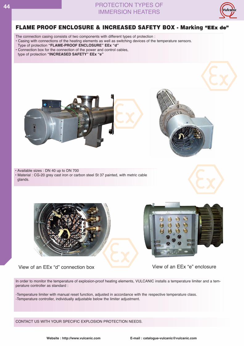
Website : http://www.vulcanic.com E-mail : [email protected]
44
FLAME PROOF ENCLOSURE & INCREASED SAFETY BOX - Marking ““EEEExx ddee””
View of an EEx “d” connection box View of an EEx “e” enclosure
In order to monitor the temperature of explosion-proof heating elements, VULCANIC installs a temperature limiter and a tem-perature controller as standard :
-Temperature limiter with manual reset function, adjusted in accordance with the respective temperature class.-Temperature controller, individually adjustable below the limiter adjustment.
PROTECTION TYPES OF IMMERSION HEATERS
• Available sizes : DN 40 up to DN 700• Material : CG-20 grey cast iron or carbon steel St 37 painted, with metric cable
glands.
The connection casing consists of two components with different types of protection :• Casing with connections of the heating elements as well as switching devices of the temperature sensors.
Type of protection “FLAME-PROOF ENCLOSURE” EEx “d”• Connection box for the connection of the power and control cables,
type of protection “INCREASED SAFETY” EEx “e”
CONTACT US WITH YOUR SPECIFIC EXPLOSION PROTECTION NEEDS.
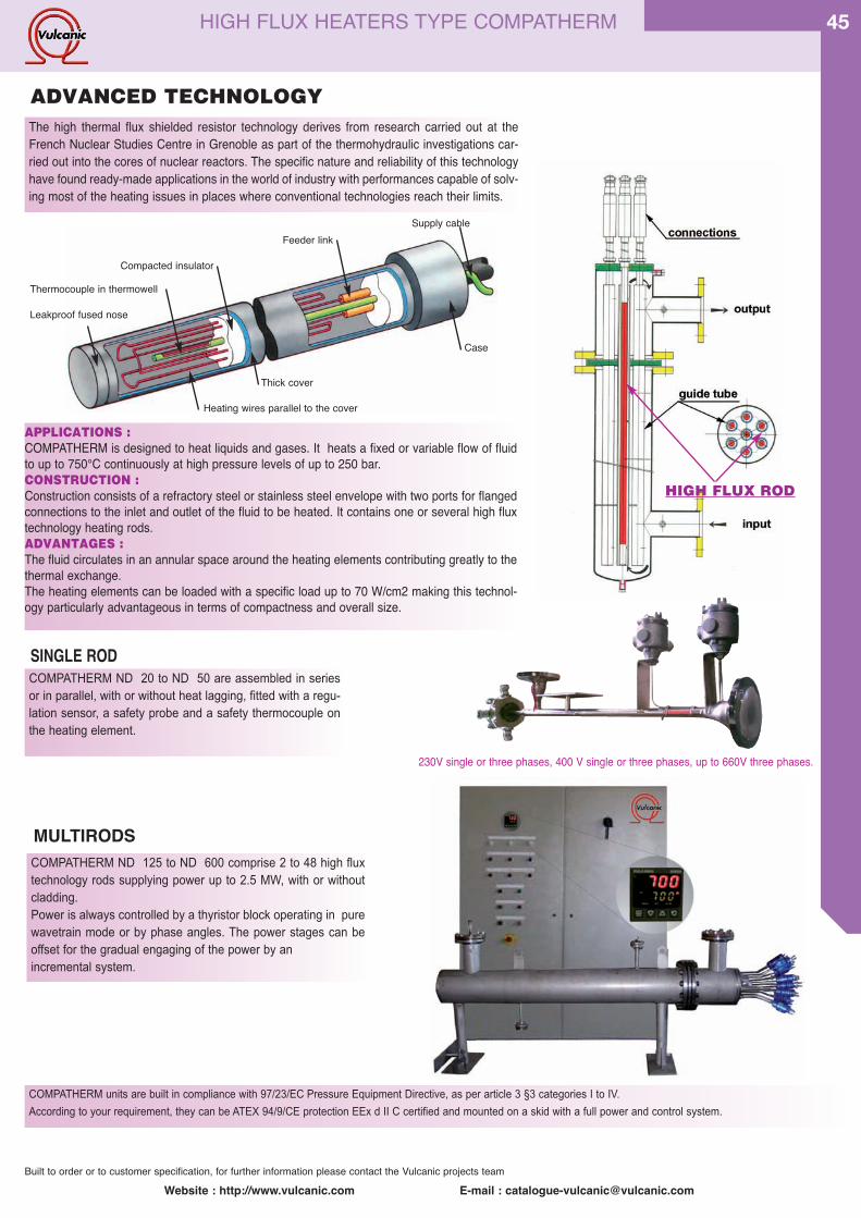
Website : http://www.vulcanic.com E-mail : [email protected]
45
The high thermal flux shielded resistor technology derives from research carried out at theFrench Nuclear Studies Centre in Grenoble as part of the thermohydraulic investigations car-ried out into the cores of nuclear reactors. The specific nature and reliability of this technologyhave found ready-made applications in the world of industry with performances capable of solv-ing most of the heating issues in places where conventional technologies reach their limits.
COMPATHERM units are built in compliance with 97/23/EC Pressure Equipment Directive, as per article 3 §3 categories I to IV.
According to your requirement, they can be ATEX 94/9/CE protection EEx d II C certified and mounted on a skid with a full power and control system.
COMPATHERM ND 20 to ND 50 are assembled in seriesor in parallel, with or without heat lagging, fitted with a regu-lation sensor, a safety probe and a safety thermocouple onthe heating element.
MULTIRODSCOMPATHERM ND 125 to ND 600 comprise 2 to 48 high fluxtechnology rods supplying power up to 2.5 MW, with or withoutcladding.Power is always controlled by a thyristor block operating in purewavetrain mode or by phase angles. The power stages can beoffset for the gradual engaging of the power by an incremental system.
APPLICATIONS :COMPATHERM is designed to heat liquids and gases. It heats a fixed or variable flow of fluidto up to 750°C continuously at high pressure levels of up to 250 bar.CONSTRUCTION :Construction consists of a refractory steel or stainless steel envelope with two ports for flangedconnections to the inlet and outlet of the fluid to be heated. It contains one or several high fluxtechnology heating rods.ADVANTAGES :The fluid circulates in an annular space around the heating elements contributing greatly to thethermal exchange. The heating elements can be loaded with a specific load up to 70 W/cm2 making this technol-ogy particularly advantageous in terms of compactness and overall size.
Thermocouple in thermowell
HIGH FLUX ROD
Leakproof fused nose
Compacted insulator
Supply cable
Case
Thick cover
Heating wires parallel to the cover
Feeder link
230V single or three phases, 400 V single or three phases, up to 660V three phases.
Built to order or to customer specification, for further information please contact the Vulcanic projects team
HIGH FLUX HEATERS TYPE COMPATHERM
ADVANCED TECHNOLOGY
SINGLE ROD
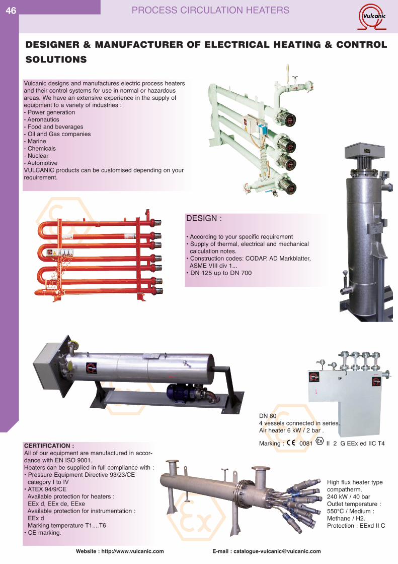
Website : http://www.vulcanic.com E-mail : [email protected]
46
DESIGNER & MANUFACTURER OF ELECTRICAL HEATING & CONTROL
SOLUTIONS
Vulcanic designs and manufactures electric process heatersand their control systems for use in normal or hazardousareas. We have an extensive experience in the supply ofequipment to a variety of industries :- Power generation- Aeronautics- Food and beverages- Oil and Gas companies- Marine- Chemicals- Nuclear- AutomotiveVULCANIC products can be customised depending on yourrequirement.
DESIGN :
• According to your specific requirement• Supply of thermal, electrical and mechanical
calculation notes.• Construction codes: CODAP, AD Markblatter,
ASME VIII div 1...• DN 125 up to DN 700
CERTIFICATION :All of our equipment are manufactured in accor-dance with EN ISO 9001.Heaters can be supplied in full compliance with : • Pressure Equipment Directive 93/23/CE
category I to IV • ATEX 94/9/CE
Available protection for heaters :EEx d, EEx de, EExeAvailable protection for instrumentation :EEx dMarking temperature T1....T6
• CE marking.
DN 804 vessels connected in series.Air heater 6 kW / 2 bar .
Marking : 0081 II 2 G EEx ed IIC T4
High flux heater typecompatherm.240 kW / 40 barOutlet temperature :550°C / Medium :Methane / H2.Protection : EExd II C
PROCESS CIRCULATION HEATERS
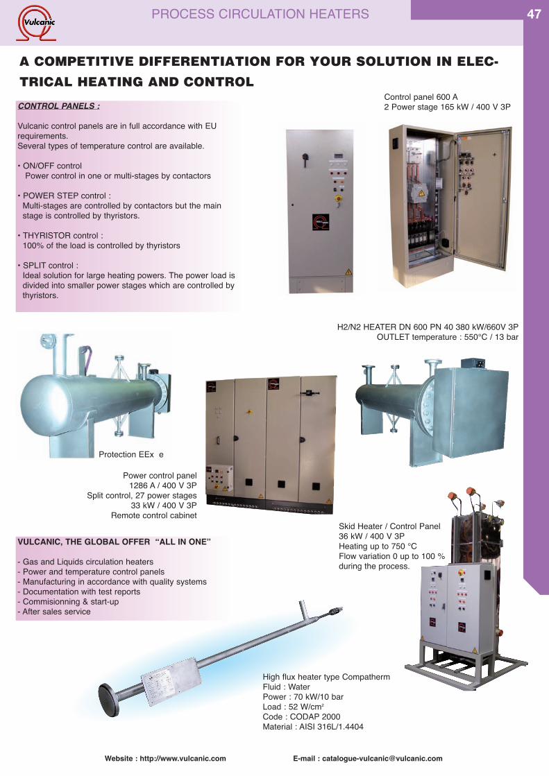
Website : http://www.vulcanic.com E-mail : [email protected]
47
DESIGNER & MANUFACTURER OF ELECTRICAL HEATING & CONTROL
SOLUTIONS
DN 804 vessels connected in series.Air heater 6 kW / 2 bar .
Marking : 0081 II 2 G EEx ed IIC T4
A COMPETITIVE DIFFERENTIATION FOR YOUR SOLUTION IN ELEC-
TRICAL HEATING AND CONTROL
CONTROL PANELS :
Vulcanic control panels are in full accordance with EU requirements.Several types of temperature control are available.
• ON/OFF control Power control in one or multi-stages by contactors
• POWER STEP control : Multi-stages are controlled by contactors but the mainstage is controlled by thyristors.
• THYRISTOR control :100% of the load is controlled by thyristors
• SPLIT control :Ideal solution for large heating powers. The power load is divided into smaller power stages which are controlled bythyristors.
Control panel 600 A 2 Power stage 165 kW / 400 V 3P
H2/N2 HEATER DN 600 PN 40 380 kW/660V 3POUTLET temperature : 550°C / 13 bar
Protection EEx e
Power control panel 1286 A / 400 V 3P
Split control, 27 power stages33 kW / 400 V 3P
Remote control cabinetSkid Heater / Control Panel36 kW / 400 V 3PHeating up to 750 °CFlow variation 0 up to 100 %during the process.
VULCANIC, THE GLOBAL OFFER “ALL IN ONEʼʼ
- Gas and Liquids circulation heaters- Power and temperature control panels- Manufacturing in accordance with quality systems- Documentation with test reports- Commisionning & start-up- After sales service
High flux heater type CompathermFluid : WaterPower : 70 kW/10 barLoad : 52 W/cm2
Code : CODAP 2000Material : AISI 316L/1.4404
PROCESS CIRCULATION HEATERS
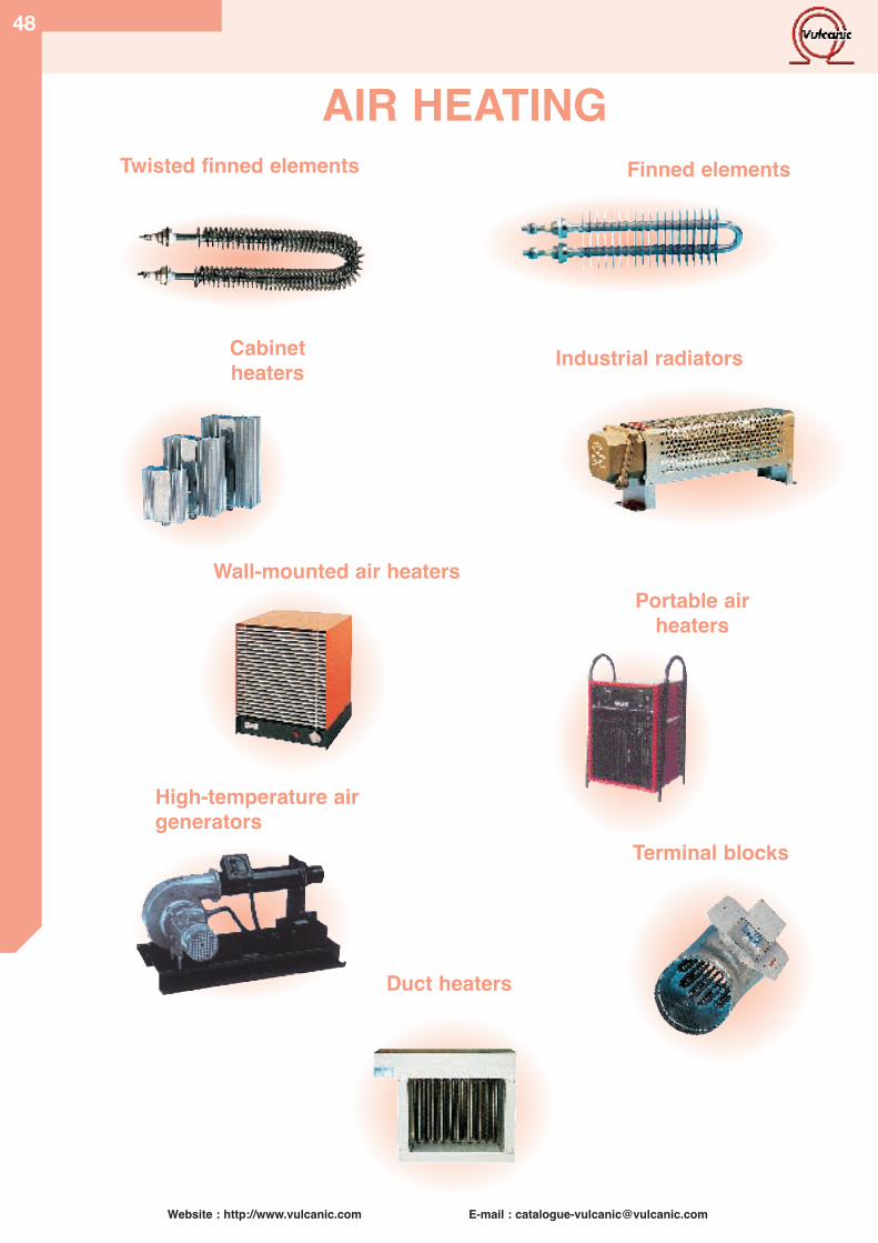
Website : http://www.vulcanic.com E-mail : [email protected]
48
1
6
7
8
9High-temperature airgenerators
Portable airheaters
Terminal blocks
AIR HEATINGFinned elementsTwisted finned elements
Wall-mounted air heaters
Duct heaters
Cabinetheaters Industrial radiators
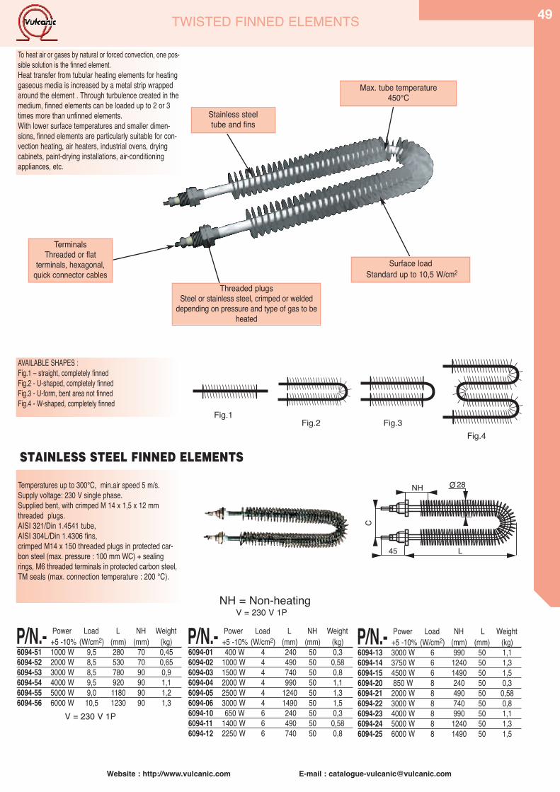
Website : http://www.vulcanic.com E-mail : [email protected]
49TWISTED FINNED ELEMENTS
AVAILABLE SHAPES :Fig.1 – straight, completely finnedFig.2 - U-shaped, completely finnedFig.3 - U-form, bent area not finnedFig.4 - W-shaped, completely finned
Stainless steeltube and fins
Max. tube temperature 450°C
Surface loadStandard up to 10,5 W/cm2
Fig.1Fig.2 Fig.3
Fig.4
Temperatures up to 300°C, min.air speed 5 m/s.Supply voltage: 230 V single phase.Supplied bent, with crimped M 14 x 1,5 x 12 mm threaded plugs.AISI 321/Din 1.4541 tube,AISI 304L/Din 1.4306 fins,crimped M14 x 150 threaded plugs in protected car-bon steel (max. pressure : 100 mm WC) + sealingrings, M6 threaded terminals in protected carbon steel,TM seals (max. connection temperature : 200 °C).
L45
C
NH 28O
P/N.- Power Load L NH Weight+5 -10% (W/cm2) (mm) (mm) (kg)
6094-01 400 W 4 240 50 0,36094-02 1000 W 4 490 50 0,586094-03 1500 W 4 740 50 0,86094-04 2000 W 4 990 50 1,16094-05 2500 W 4 1240 50 1,36094-06 3000 W 4 1490 50 1,56094-10 650 W 6 240 50 0,36094-11 1400 W 6 490 50 0,586094-12 2250 W 6 740 50 0,8
P/N.- Power Load L NH Weight+5 -10% (W/cm2) (mm) (mm) (kg)
6094-51 1000 W 9,5 280 70 0,456094-52 2000 W 8,5 530 70 0,656094-53 3000 W 8,5 780 90 0,96094-54 4000 W 9,5 920 90 1,16094-55 5000 W 9,0 1180 90 1,26094-56 6000 W 10,5 1230 90 1,3
P/N.- Power Load NH L Weight+5 -10% (W/cm2) (mm) (mm) (kg)
6094-13 3000 W 6 990 50 1,16094-14 3750 W 6 1240 50 1,36094-15 4500 W 6 1490 50 1,56094-20 850 W 8 240 50 0,36094-21 2000 W 8 490 50 0,586094-22 3000 W 8 740 50 0,86094-23 4000 W 8 990 50 1,16094-24 5000 W 8 1240 50 1,36094-25 6000 W 8 1490 50 1,5
STAINLESS STEEL FINNED ELEMENTS
TerminalsThreaded or flat
terminals, hexagonal,quick connector cables
Threaded plugsSteel or stainless steel, crimped or welded
depending on pressure and type of gas to beheated
NH = Non-heating
V = 230 V 1P
V = 230 V 1P
To heat air or gases by natural or forced convection, one pos-sible solution is the finned element. Heat transfer from tubular heating elements for heatinggaseous media is increased by a metal strip wrappedaround the element . Through turbulence created in themedium, finned elements can be loaded up to 2 or 3times more than unfinned elements.With lower surface temperatures and smaller dimen-sions, finned elements are particularly suitable for con-vection heating, air heaters, industrial ovens, dryingcabinets, paint-drying installations, air-conditioningappliances, etc.
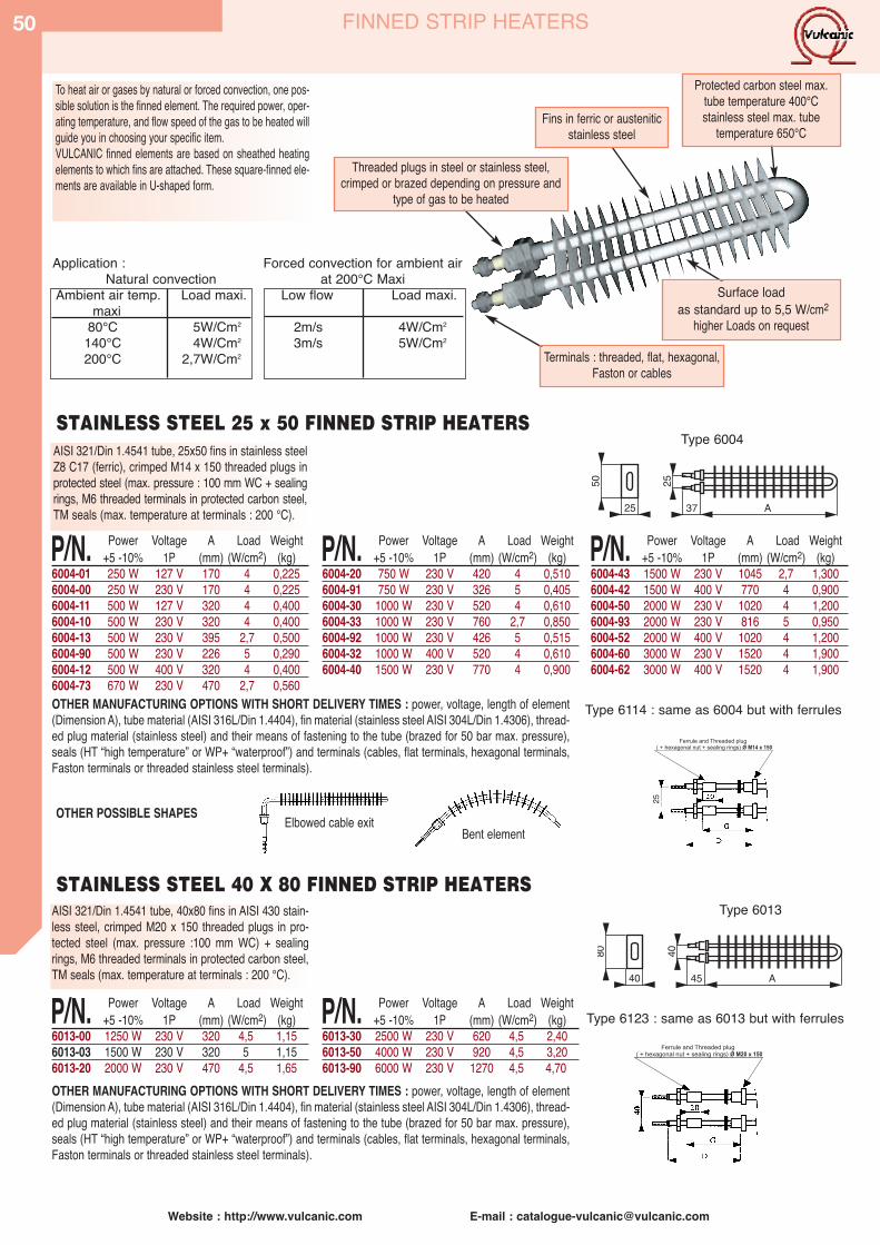
Website : http://www.vulcanic.com E-mail : [email protected]
50 FINNED STRIP HEATERS
To heat air or gases by natural or forced convection, one pos-sible solution is the finned element. The required power, oper-ating temperature, and flow speed of the gas to be heated willguide you in choosing your specific item.VULCANIC finned elements are based on sheathed heatingelements to which fins are attached. These square-finned ele-ments are available in U-shaped form.
Fins in ferric or austeniticstainless steel
Protected carbon steel max.tube temperature 400°Cstainless steel max. tube
temperature 650°C
Terminals : threaded, flat, hexagonal,Faston or cables
Threaded plugs in steel or stainless steel,crimped or brazed depending on pressure and
type of gas to be heated
Surface loadas standard up to 5,5 W/cm2
higher Loads on request
2550
25 37 A
P/N. Power Voltage A Load Weight+5 -10% 1P (mm) (W/cm2) (kg)
6004-01 250 W 127 V 170 4 0,2256004-00 250 W 230 V 170 4 0,2256004-11 500 W 127 V 320 4 0,4006004-10 500 W 230 V 320 4 0,4006004-13 500 W 230 V 395 2,7 0,5006004-90 500 W 230 V 226 5 0,2906004-12 500 W 400 V 320 4 0,4006004-73 670 W 230 V 470 2,7 0,560
P/N. Power Voltage A Load Weight+5 -10% 1P (mm) (W/cm2) (kg)
6004-20 750 W 230 V 420 4 0,5106004-91 750 W 230 V 326 5 0,4056004-30 1000 W 230 V 520 4 0,6106004-33 1000 W 230 V 760 2,7 0,8506004-92 1000 W 230 V 426 5 0,5156004-32 1000 W 400 V 520 4 0,6106004-40 1500 W 230 V 770 4 0,900
P/N. Power Voltage A Load Weight+5 -10% 1P (mm) (W/cm2) (kg)
6004-43 1500 W 230 V 1045 2,7 1,3006004-42 1500 W 400 V 770 4 0,9006004-50 2000 W 230 V 1020 4 1,2006004-93 2000 W 230 V 816 5 0,9506004-52 2000 W 400 V 1020 4 1,2006004-60 3000 W 230 V 1520 4 1,9006004-62 3000 W 400 V 1520 4 1,900
AISI 321/Din 1.4541 tube, 25x50 fins in stainless steelZ8 C17 (ferric), crimped M14 x 150 threaded plugs inprotected steel (max. pressure : 100 mm WC + sealingrings, M6 threaded terminals in protected carbon steel,TM seals (max. temperature at terminals : 200 °C).
AISI 321/Din 1.4541 tube, 40x80 fins in AISI 430 stain-less steel, crimped M20 x 150 threaded plugs in pro-tected steel (max. pressure :100 mm WC) + sealingrings, M6 threaded terminals in protected carbon steel,TM seals (max. temperature at terminals : 200 °C).
OTHER MANUFACTURING OPTIONS WITH SHORT DELIVERY TIMES : power, voltage, length of element(Dimension A), tube material (AISI 316L/Din 1.4404), fin material (stainless steel AISI 304L/Din 1.4306), thread-ed plug material (stainless steel) and their means of fastening to the tube (brazed for 50 bar max. pressure),seals (HT “high temperature” or WP+ “waterproof”) and terminals (cables, flat terminals, hexagonal terminals,Faston terminals or threaded stainless steel terminals).
OTHER MANUFACTURING OPTIONS WITH SHORT DELIVERY TIMES : power, voltage, length of element(Dimension A), tube material (AISI 316L/Din 1.4404), fin material (stainless steel AISI 304L/Din 1.4306), thread-ed plug material (stainless steel) and their means of fastening to the tube (brazed for 50 bar max. pressure),seals (HT “high temperature” or WP+ “waterproof”) and terminals (cables, flat terminals, hexagonal terminals,Faston terminals or threaded stainless steel terminals).
4080
40 45 A
P/N. Power Voltage A Load Weight+5 -10% 1P (mm) (W/cm2) (kg)
6013-00 1250 W 230 V 320 4,5 1,156013-03 1500 W 230 V 320 5 1,156013-20 2000 W 230 V 470 4,5 1,65
P/N. Power Voltage A Load Weight+5 -10% 1P (mm) (W/cm2) (kg)
6013-30 2500 W 230 V 620 4,5 2,406013-50 4000 W 230 V 920 4,5 3,206013-90 6000 W 230 V 1270 4,5 4,70
Ferrule and Threaded plug( + hexagonal nut + sealing rings) Ø M14 x 150
25
Ferrule and Threaded plug( + hexagonal nut + sealing rings) Ø M20 x 150
STAINLESS STEEL 25 x 50 FINNED STRIP HEATERS
OTHER POSSIBLE SHAPES Elbowed cable exitBent element
STAINLESS STEEL 40 X 80 FINNED STRIP HEATERS
Application :Natural convection
Ambient air temp. Load maxi.maxi
80°C 5W/Cm2
140°C 4W/Cm2
200°C 2,7W/Cm2
Forced convection for ambient airat 200°C Maxi
Low flow Load maxi.
2m/s 4W/Cm2
3m/s 5W/Cm2
Type 6004
Type 6114 : same as 6004 but with ferrules
Type 6123 : same as 6013 but with ferrules
Type 6013
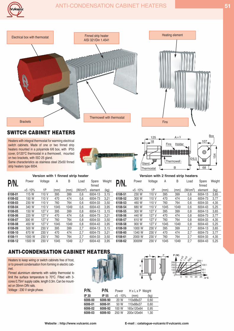
Website : http://www.vulcanic.com E-mail : [email protected]
51ANTI-CONDENSATION CABINET HEATERS
Heaters to keep wiring or switch cabinets free of frost,or to prevent condensation from forming in electric cab-inet.Finned aluminium elements with safety thermostat tolimit the surface temperature to 70°C. Fitted with 3-cores 0,75m2 supply cable, length 0.3m. Can be mount-ed on 35mm DIN rails. Voltage : 230 V single phase.
20H
L P P (W)
250 200 l500 l
1 m3
2 m3
100 l50 l10 l
200150100
500 0 10 15 20 25 Δt°C
P/N. P/N. Power H x L x P WeightIP 30 IP 55 +5 -10% (mm) (kg)6006-00 6006-90 20 W 110x88x37 0,606006-01 6006-91 50 W 110x88x37 0,606006-02 6006-92 100 W 165x120x64 0,956006-03 6006-93 250 W 200x120x64 1,30
ANTI-CONDENSATION CABINET HEATERS
Heaters with integral thermostat for warming electricalswitch cabinets. Made of one or two finned stripheaters mounted in a polyamide 6/6 box, with IP55cover, 0/120°C thermostat in a thermowell, mountedon two brackets, with ISO 25 gland.Same characteristics as stainless steel 25x50 finnedstrip heaters type 6004. B 68
18125 A
107
154
Fins Holder
Thermowell (ddg)
Box
Gland6,5
Thermostat
O
SWITCH CABINET HEATERS
Version with 2 finned strip heaters
P/N. Power Voltage A B Load Spare Weightfinned
+5 -10% 1P (mm) (mm) (W/cm2) element (kg)6108-51 230 W 110 V 395 399 0,6 6004-13 3,656108-52 300 W 110 V 470 474 0,6 6004-73 3,776108-53 460 W 110 V 760 764 0,6 6004-33 4,356108-54 680 W 110 V 1045 1049 0,6 6004-43 5,256108-55 300 W 127 V 395 399 0,8 6004-13 3,656108-56 440 W 127 V 470 474 0,8 6004-73 3,776108-57 610 W 127 V 760 764 0,8 6004-33 4,356108-58 900 W 127 V 1045 1049 0,8 6004-43 5,256108-59 1000 W 230 V 395 399 2,7 6004-13 3,656108-60 1340 W 230 V 470 474 2,7 6004-73 3,776108-61 2000 W 230 V 760 764 2,7 6004-33 4,356108-62 3000W 230 V 1045 1049 2,7 6004-43 5,25
Version with 1 finned strip heater
P/N. Power Voltage A B Load Spare Weightfinned
+5 -10% 1P (mm) (mm) (W/cm2) element (kg)6108-01 115 W 110 V 395 399 0,6 6004-13 3,156108-02 150 W 110 V 470 474 0,6 6004-73 3,216108-03 230 W 110 V 760 764 0,6 6004-33 3,506108-04 340 W 110 V 1045 1049 0,6 6004-43 3,956108-05 150 W 127 V 395 399 0,8 6004-13 3,156108-06 220 W 127 V 470 474 0,8 6004-73 3,216108-07 300 W 127 V 760 764 0,8 6004-33 3,506108-08 450 W 127 V 1045 1049 0,8 6004-43 3,956108-09 500 W 230 V 395 399 2,7 6004-13 3,156108-10 670 W 230 V 470 474 2,7 6004-73 3,216108-11 1000 W 230 V 760 764 2,7 6004-33 3,506108-12 1500 W 230 V 1045 1049 2,7 6004-43 3,95
Finned strip heaterAISI 321/Din 1.4541Electrical box with thermostat
BracketsThermowell with thermostat
Fins
Heating element
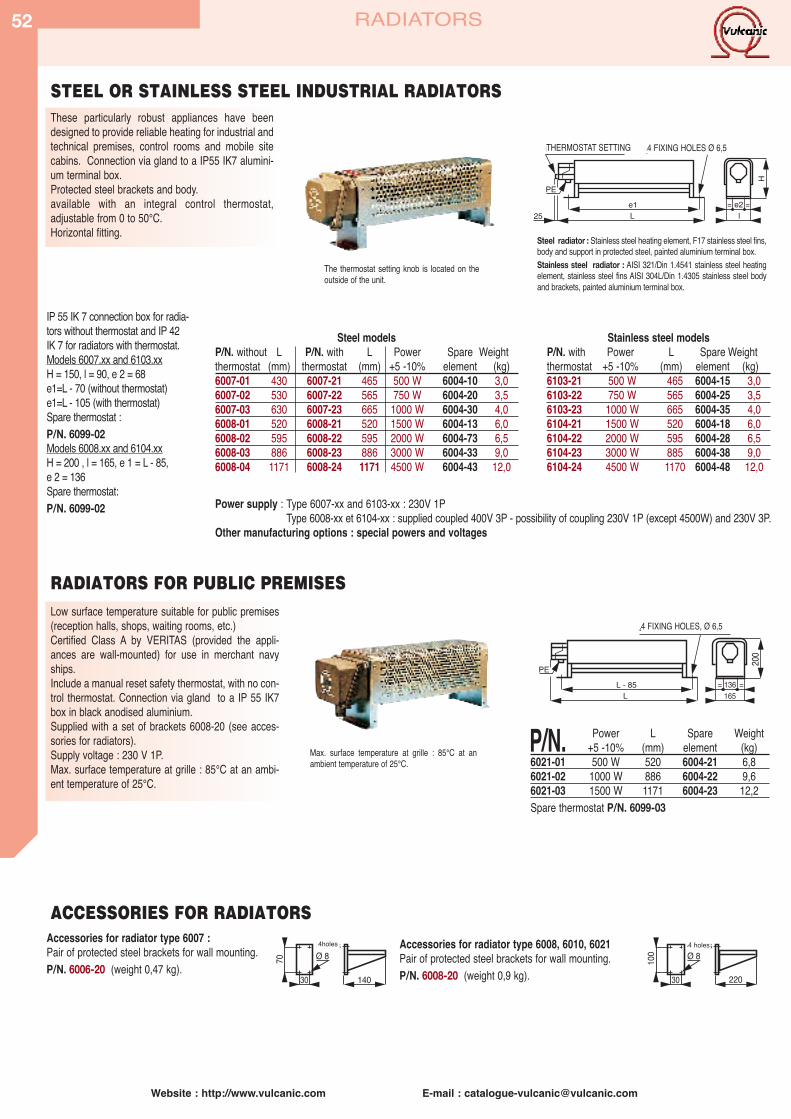
Website : http://www.vulcanic.com E-mail : [email protected]
52
These particularly robust appliances have beendesigned to provide reliable heating for industrial andtechnical premises, control rooms and mobile sitecabins. Connection via gland to a IP55 IK7 alumini-um terminal box.Protected steel brackets and body.available with an integral control thermostat,adjustable from 0 to 50°C.Horizontal fitting.
The thermostat setting knob is located on theoutside of the unit.
Steel radiator : Stainless steel heating element, F17 stainless steel fins,body and support in protected steel, painted aluminium terminal box.Stainless steel radiator : AISI 321/Din 1.4541 stainless steel heatingelement, stainless steel fins AISI 304L/Din 1.4305 stainless steel bodyand brackets, painted aluminium terminal box.
25e1L l
e2= =
H
REGLAGE THERMOSTAT 4 TROUS DE FIXATION Ø 6,5
PE
Low surface temperature suitable for public premises(reception halls, shops, waiting rooms, etc.)Certified Class A by VERITAS (provided the appli-ances are wall-mounted) for use in merchant navyships.Include a manual reset safety thermostat, with no con-trol thermostat. Connection via gland to a IP 55 IK7box in black anodised aluminium. Supplied with a set of brackets 6008-20 (see acces-sories for radiators).Supply voltage : 230 V 1P.Max. surface temperature at grille : 85°C at an ambi-ent temperature of 25°C.
L - 85L 165
136= =
200
4 TROUS DE FIXATION Ø 6,5
PE
Accessories for radiator type 6007 :Pair of protected steel brackets for wall mounting.P/N. 6006-20 (weight 0,47 kg).
Power supply : Type 6007-xx and 6103-xx : 230V 1PType 6008-xx et 6104-xx : supplied coupled 400V 3P - possibility of coupling 230V 1P (except 4500W) and 230V 3P.
Other manufacturing options : special powers and voltages
Accessories for radiator type 6008, 6010, 6021Pair of protected steel brackets for wall mounting.P/N. 6008-20 (weight 0,9 kg).30 140
4 trousØ 870
30 220
4 trousØ 810
0
STEEL OR STAINLESS STEEL INDUSTRIAL RADIATORS
RADIATORS FOR PUBLIC PREMISES
ACCESSORIES FOR RADIATORS
Steel modelsP/N. without L P/N. with L Power Spare Weightthermostat (mm) thermostat (mm) +5 -10% element (kg)6007-01 430 6007-21 465 500 W 6004-10 3,06007-02 530 6007-22 565 750 W 6004-20 3,56007-03 630 6007-23 665 1000 W 6004-30 4,06008-01 520 6008-21 520 1500 W 6004-13 6,06008-02 595 6008-22 595 2000 W 6004-73 6,56008-03 886 6008-23 886 3000 W 6004-33 9,06008-04 1171 6008-24 1171 4500 W 6004-43 12,0
Stainless steel modelsP/N. with Power L Spare Weightthermostat +5 -10% (mm) element (kg)6103-21 500 W 465 6004-15 3,06103-22 750 W 565 6004-25 3,56103-23 1000 W 665 6004-35 4,06104-21 1500 W 520 6004-18 6,06104-22 2000 W 595 6004-28 6,56104-23 3000 W 885 6004-38 9,06104-24 4500 W 1170 6004-48 12,0
P/N. Power L Spare Weight+5 -10% (mm) element (kg)
6021-01 500 W 520 6004-21 6,86021-02 1000 W 886 6004-22 9,66021-03 1500 W 1171 6004-23 12,2Spare thermostat P/N. 6099-03
Max. surface temperature at grille : 85°C at anambient temperature of 25°C.
IP 55 IK 7 connection box for radia-tors without thermostat and IP 42 IK 7 for radiators with thermostat.Models 6007.xx and 6103.xxH = 150, l = 90, e 2 = 68e1=L - 70 (without thermostat)e1=L - 105 (with thermostat) Spare thermostat :P/N. 6099-02Models 6008.xx and 6104.xxH = 200 , l = 165, e 1 = L - 85,e 2 = 136Spare thermostat:P/N. 6099-02
THERMOSTAT SETTING 4 FIXING HOLES Ø 6,5
4 FIXING HOLES, Ø 6,5
RADIATORS
4holes 4 holes

Website : http://www.vulcanic.com E-mail : [email protected]
53
These particularly robust appliances have been designed to provide reliable heating at 40°Cmaximum for industrial premises, paint shops,inflammable product storage areas, petrol stations,drilling rigs, etc.Connection via gland to an IP55 IK07 box, protectedsteel brackets and body. Horizontal fixing.Include an integral control thermostat adjustablefrom 0-50°C.
L - 102 136= =10
50
275
4 TROUS DE FIXATION Ø 6,5
ENTRETOISE H = 50 POUR FIXATION AU SOL-(DEMONTABLE SI FIXATION MURALE SUR CONSOLES)
PE POUR CABLE Ø 12 à 17L 165
EExd II C T3 model (max. temperature of heating elementlocated inside the vessel 200°C, at an ambient tempera-ture of 40°C). Certified by the LCIE ( certificate Nr : LCIE03 Atex 6282X) for use in explosive environments (direc-tive 94/9/CE) under P/N. CE 0081Ex II 2G EEx d II c T.
P/N. Power L Spare Weight+5 -10% (mm) element (kg)
6010-62 750 W 612 6099-51 126010-63 1260 W 902 6099-52 186010-64 2000 W 1187 6099-53 24
P/N. Power L Spare Weight+5 -10% (mm) element (kg)
6010-68 750 W 612 6099-51 126010-69 1260 W 902 6099-52 186010-70 2000 W 1187 6099-53 24
P/N. Power L Spare Weight+5 -10% (mm) element (kg)
6010-65 750 W 612 6099-51 126010-66 1260 W 902 6099-52 186010-67 2000 W 1187 6099-53 24
SPACER H = 50 FOR FLOOR FIXING(CAN BE REMOVED IF WALL-MOUNTED ON BRACKETS)
4 FIXING HOLES, Ø 6,5
LEAD GLAND Ø 12 to17
EXPLOSION-PROOFRADIATORS
EExd IIC T3 CERTIFIED RADIATORS
P/N. Type Power Voltage Length ET Overall length L Load (kW) (V) (mm) (mm) (W/cm2)
6022-01 ExHBG- 500-30-S 0,5 230 250 510 0,36022-02 ExHBG-1000-30-S 1 230 400 660 0,36022-03 ExHBG-1500-30-S 1,5 230 600 860 0,36022-03 EXHBG-2000-30-S 2 230 700 960 0,36022-03 ExHBG-3000-30-S 3 400 1000 1260 0,36022-03 ExHBG-4000-30-S 4 400 1500 1760 0,3
All materials are in stainless steelTemperature class T3. .Ignition protection type EEx de IIC.Connection box is IP 66 in painted cast iron.
Fixing:Space heaters should only be installed horizontally. Care must be taken that free thermal convection is nothindered.Please follow our instructions for use, P/N. BA-0104.For precise regulation of room temperature, we recommend the use of a room regulator, P/N. 94-09019-07.
Ø12
0
ET
90
130
140
L
ca.24510
0 ca.1
80
Ø14 (2x)
PE
Kabelverschraubung
-30
EXPLOSION-PROOF THERMOSTATSSuitable for monitoring and regulating room temperature. Can be used directly in hazardous area Zone 1Type of protection: EEx de IIC T6Cover type: IP65Switching capacity: 230VAC/10A.
P/N. Range Ø Type Weight(°C) (mm) (kg)
6023-01 -20+40 35 x 70 Regulator 0,6
Space heaters are certified devices for heating air or gases by convection. They comprise three main components:a) Heating insert made up of electric heating elementsb) Flame proof (Ex de) enclosure with limiter and regulatorc) Protective cover with supporting feet.This model complies with European standards EN 50014, EN 50018, and EN 50019.All devices are equipped with flame-proof (Ex de) type of explosion protection " for use withGas Group IIC, i.e. They can be used anywhere in Zones 1 and 2 (Category 2 or 3).Standard model appliances are permissible for Temperature Class T3.Certified devices can also be designed for all other Temperature Classes between T6and T1.Components are made in our own workshops under quality control and tested individually asa complete assembly. The results of the test are included in the test certificate. In the standard model, a temperature limiter and a temperature regulator are built into the heater. Both these switching devices have the func-tion of monitoring and regulating the temperature of the heater surface.The main industrial applications are Petrochemicals / Offshore oil drilling, Chemical works,storage tanks, painting shops ....Advantages:- Easy to install, Light and portable, Small in size, Customised versions available.
Supply voltage: 230 V 1P Supply voltage: 230 V 3P Supply voltage : 400V 3P
cable gland
Marking II 2 G EEx d IIC T3Certificate : LCIE 03 Atex 6282XParticular precautions must be taken to secure the operation of this product.Consult us or read the instruction manual.
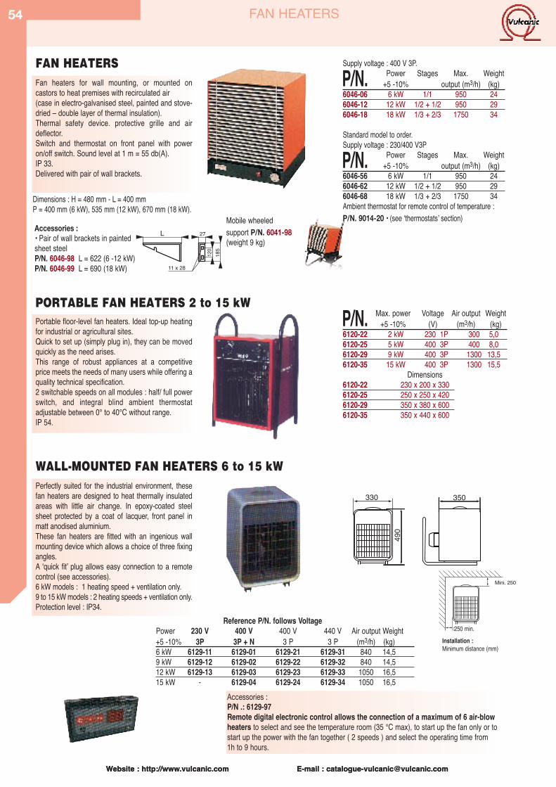
Website : http://www.vulcanic.com E-mail : [email protected]
54
Website : http://www.vulcanic.com E-mail : [email protected]
Fan heaters for wall mounting, or mounted on castors to heat premises with recirculated air(case in electro-galvanised steel, painted and stove-dried – double layer of thermal insulation).Thermal safety device. protective grille and airdeflector.Switch and thermostat on front panel with poweron/off switch. Sound level at 1 m = 55 db(A). IP 33.Delivered with pair of wall brackets.
120
185
27L
11 x 28
Dimensions : H = 480 mm - L = 400 mmP = 400 mm (6 kW), 535 mm (12 kW), 670 mm (18 kW).
Perfectly suited for the industrial environment, thesefan heaters are designed to heat thermally insulatedareas with little air change. In epoxy-coated steelsheet protected by a coat of lacquer, front panel inmatt anodised aluminium.These fan heaters are fitted with an ingenious wallmounting device which allows a choice of three fixingangles.A ʻquick fit ̓plug allows easy connection to a remotecontrol (see accessories).6 kW models : 1 heating speed + ventilation only.9 to 15 kW models : 2 heating speeds + ventilation only.Protection level : IP34.
Accessories :• Pair of wall brackets in paintedsheet steelP/N. 6046-98 L = 622 (6 -12 kW)P/N. 6046-99 L = 690 (18 kW)
Reference P/N. follows VoltagePower 230 V 400 V 400 V 440 V Air output Weight+5 -10% 3P 3P + N 3 P 3 P (m3/h) (kg)6 kW 6129-11 6129-01 6129-21 6129-31 840 14,59 kW 6129-12 6129-02 6129-22 6129-32 840 14,512 kW 6129-13 6129-03 6129-23 6129-33 1050 16,515 kW - 6129-04 6129-24 6129-34 1050 16,5
Supply voltage : 400 V 3P.
P/N. Power Stages Max. Weight+5 -10% output (m3/h) (kg)
6046-06 6 kW 1/1 950 246046-12 12 kW 1/2 + 1/2 950 296046-18 18 kW 1/3 + 2/3 1750 34
Standard model to order.Supply voltage : 230/400 V3P
P/N. Power Stages Max. Weight+5 -10% output (m3/h) (kg)
6046-56 6 kW 1/1 950 246046-62 12 kW 1/2 + 1/2 950 296046-68 18 kW 1/3 + 2/3 1750 34Ambient thermostat for remote control of temperature : P/N. 9014-20 • (see ʻthermostats ̓section)Mobile wheeled
support P/N. 6041-98(weight 9 kg)
FAN HEATERS
Portable floor-level fan heaters. Ideal top-up heatingfor industrial or agricultural sites.Quick to set up (simply plug in), they can be movedquickly as the need arises.This range of robust appliances at a competitiveprice meets the needs of many users while offering aquality technical specification. 2 switchable speeds on all modules : half/ full powerswitch, and integral blind ambient thermostatadjustable between 0° to 40°C without range.IP 54.
PORTABLE FAN HEATERS 2 to 15 kWP/N. Max. power Voltage Air output Weight
+5 -10% (V) (m3/h) (kg)6120-22 2 kW 230 1P 300 5,06120-25 5 kW 400 3P 400 8,06120-29 9 kW 400 3P 1300 13,56120-35 15 kW 400 3P 1300 15,5
Dimensions6120-22 230 x 200 x 3306120-25 250 x 250 x 4206120-29 350 x 380 x 6006120-35 350 x 440 x 600
WALL-MOUNTED FAN HEATERS 6 to 15 kW
FAN HEATERS
350330
490
Mini. 250
Mini. 250
Installation : Minimum distance (mm)
250 min.
Accessories :P/N .: 6129-97Remote digital electronic control allows the connection of a maximum of 6 air-blowheaters to select and see the temperature room (35 °C max), to start up the fan only or tostart up the power with the fan together ( 2 speeds ) and select the operating time from1h to 9 hours.

Website : http://www.vulcanic.com E-mail : [email protected]
55FAN HEATERS – CONVECTOR HEATERS – HOT AIR CURTAINS
Specification of listed models with short delivery time :Body in protected steel sheet. Stainless steel finned strip heaters (tube in AISI 312/Din 1.4541, fins in Z8 C17). Spiral fan with large blades, and motor (1000 or 1500rpm, depending on model) with IP55 connection box. Safety thermostat set at 110°C, automatic reset. Connection of two power stages and safety thermostat in anIP30 box with 3 glands (2 for the power stages and 1 for the safety device).
P/N. Power Voltage over heating L H l A B C Stages ØFan Speed run. output Weight+5 -10% (V Tri) (°C) (mm) (mm) (mm) (mm) (mm) (mm) (kW) (mm) (t/mn) (m3/h) (kg)
6016-01 4,5 400 8 355 440 284 500 280 150 2,25+2,25 300 1000 1250 246016-02 6,75 400 12 355 440 334 550 280 200 2,25+4,50 300 1000 1200 276016-03 9 400 16 355 440 334 550 280 200 2,25+6,75 300 1000 1150 306016-04 11,25 400 20 355 440 334 550 280 200 4,50+6,75 300 1000 1100 326016-05 15,75 400 28 355 440 384 600 280 250 4,50+11,25 300 1000 1050 366016-06 18 400 32 355 540 384 600 280 250 6 +12 300 1000 1000 386016-07 21 400 26 395 540 384 605 280 250 6 +15 350 1500 1500 496016-08 24 400 30 395 540 384 605 280 250 9 +15 350 1500 1300 526016-09 27 400 12 435 540 384 605 350 250 9 +15 400 1500 2750 566016-10 30 400 13 435 540 384 615 350 250 12 +18 400 1500 2500 586016-11 33 400 14 435 540 434 665 350 300 12 +21 400 1500 2250 616016-12 36 400 16 435 540 434 665 350 300 12 +24 400 1500 2000 666016-13 40,5 400 13 515 790 384 675 350 250 13,50+27 450 1500 4000 746016-14 45 400 14 515 790 384 675 350 250 13,50+31,50 450 1500 3800 796016-15 49,5 400 16 515 790 384 675 350 250 18 +31,50 450 1500 3600 836016-16 54 400 17 515 790 384 675 350 250 18 +36 450 1500 3400 876016-17 58,5 400 15 555 790 384 695 350 250 22,50+36 500 1500 5200 996016-18 63 400 16 555 790 434 695 350 300 22,50+40,50 500 1500 5000 1046016-19 67,5 400 17 555 790 434 695 350 300 22,50+45 500 1500 4800 109Accessory : Pair of wall fixing brackets : P/N. 6059-01 for 30kW max.power models (Weight : 9 kg).Other manufacturing options : Power, Voltage, number of stages, body material (stainless steel), sealing of the IP55 terminal box, etc.
Fan heaters of simple and robust design for heat-ing recirculated air in areas such as workshops,factory shopfloors, warehouses, refectories,sports halls, garages, shops, greenhouse ...These appliances are not fitted with any controlsystem. Max. working temperature : 45°C.
Economical hot air curtains suitable for single door-ways. The heater can be wall - or ceiling -mountedat a height between 1,8m and 3m above floor leveland a minimum of 300m from adjacent walls . Hot aircurtains set up a thermal barrier between two placesof very different temperature. They help toeconomise on heating and air-conditioning in the pro-tected area. Mounting kit included.
225
108
Air exit
Air entry
635HOT AIR CURTAINS 3kW
P/N. Power Voltage No LOutput Weight+5 -10% V of stages m3/h (kg)
6122-01 3 kW 230 1 250 76122-02 as 6122-01 but with electronic thermostat.
Convector heaters designed for heating houses, offices or technical sites open to the public. They arerobust, pleasant to look at, and conform to Europeanstandards. Fitted with an on/off switch and an elec-tronic ambiant thermostat measuring the tempera-ture at the air entry point, with the option of mechan-ical locking to a temperature range or to one set tem-perature. ʻFrost guardʼ position set to approx. 7°C.Supply voltage: 230 V single phase.
All these convector heaters are double insulated (class2) , and can be installed near water draw-off points asdefined in regulations.Electronic ambient air control : see ʻthermostatsʼ section.
CONVECTOR HEATERS P/N. Power L H D Weight+5 -10% (mm) (mm) (mm) (kg)
6045-10 1000 W 420 430 83 4,66045-15 1500 W 580 430 83 66045-20 2000 W 740 430 83 7,6
Al 100 mini
3540
700C 31
5
BL50 50
10=
100
100
5050
H
Ventilateur hélicoïdal
4 trous oblongsde fixation
10 x 35
=Consoles
(accessoires)
INDUSTRIAL FAN HEATERS WITHOUT REGULATION
Spiral fan
100 min.
4 oblong fixingholes 10 x 35
Brackets(accessories)
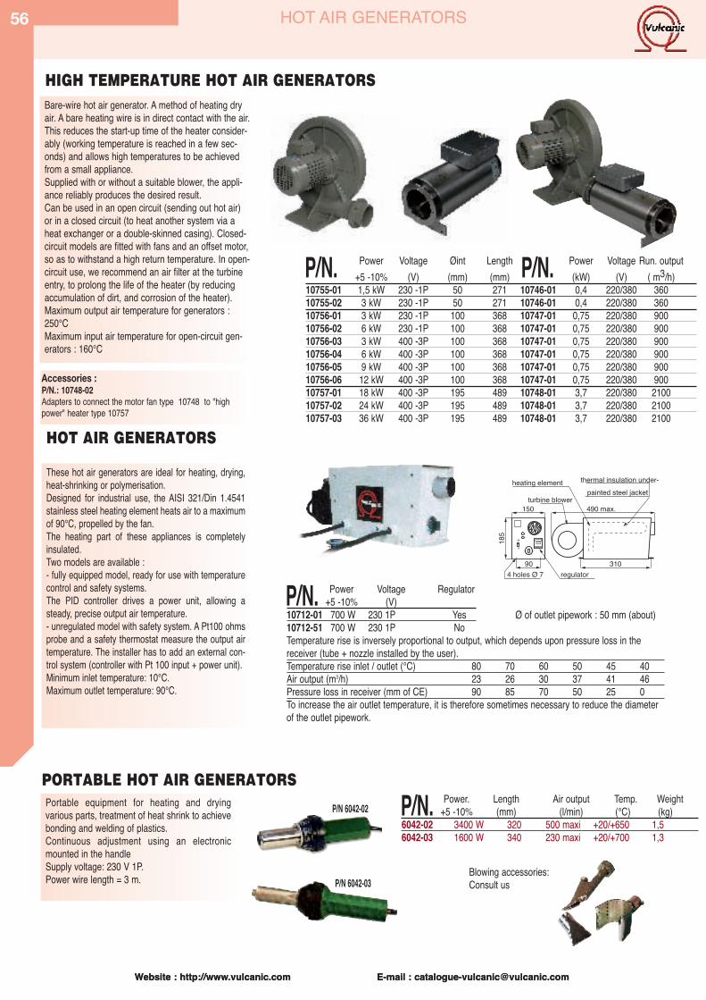
Website : http://www.vulcanic.com E-mail : [email protected]
56
Website : http://www.vulcanic.com E-mail : [email protected]
HOT AIR GENERATORS
Bare-wire hot air generator. A method of heating dryair. A bare heating wire is in direct contact with the air.This reduces the start-up time of the heater consider-ably (working temperature is reached in a few sec-onds) and allows high temperatures to be achievedfrom a small appliance.Supplied with or without a suitable blower, the appli-ance reliably produces the desired result.Can be used in an open circuit (sending out hot air)or in a closed circuit (to heat another system via aheat exchanger or a double-skinned casing). Closed-circuit models are fitted with fans and an offset motor,so as to withstand a high return temperature. In open-circuit use, we recommend an air filter at the turbineentry, to prolong the life of the heater (by reducingaccumulation of dirt, and corrosion of the heater).Maximum output air temperature for generators :250°CMaximum input air temperature for open-circuit gen-erators : 160°C
HIGH TEMPERATURE HOT AIR GENERATORS
HOT AIR GENERATORS
These hot air generators are ideal for heating, drying,heat-shrinking or polymerisation.Designed for industrial use, the AISI 321/Din 1.4541stainless steel heating element heats air to a maximumof 90°C, propelled by the fan. The heating part of these appliances is completelyinsulated.Two models are available :- fully equipped model, ready for use with temperaturecontrol and safety systems. The PID controller drives a power unit, allowing asteady, precise output air temperature.- unregulated model with safety system. A Pt100 ohmsprobe and a safety thermostat measure the output airtemperature. The installer has to add an external con-trol system (controller with Pt 100 input + power unit).Minimum inlet temperature: 10°C.Maximum outlet temperature: 90°C.
M
A
185
150
31090regulator
490 max.turbine blower
thermal insulation under-heating elementpainted steel jacket
P/N. Power Voltage Regulator+5 -10% (V)
10712-01 700 W 230 1P Yes10712-51 700 W 230 1P NoTemperature rise is inversely proportional to output, which depends upon pressure loss in thereceiver (tube + nozzle installed by the user).Temperature rise inlet / outlet (°C) 80 70 60 50 45 40Air output (m3/h) 23 26 30 37 41 46Pressure loss in receiver (mm of CE) 90 85 70 50 25 0To increase the air outlet temperature, it is therefore sometimes necessary to reduce the diameterof the outlet pipework.
Ø of outlet pipework : 50 mm (about)
Accessories :P/N.: 10748-02Adapters to connect the motor fan type 10748 to "highpower" heater type 10757
P/N.REF. Power Voltage Øint Length Power Voltage Run. output+5 -10% (V) (mm) (mm) (kW) (V) ( m3/h)
10755-01 1,5 kW 230 -1P 50 271 10746-01 0,4 220/380 36010755-02 3 kW 230 -1P 50 271 10746-01 0,4 220/380 36010756-01 3 kW 230 -1P 100 368 10747-01 0,75 220/380 90010756-02 6 kW 230 -1P 100 368 10747-01 0,75 220/380 90010756-03 3 kW 400 -3P 100 368 10747-01 0,75 220/380 90010756-04 6 kW 400 -3P 100 368 10747-01 0,75 220/380 90010756-05 9 kW 400 -3P 100 368 10747-01 0,75 220/380 90010756-06 12 kW 400 -3P 100 368 10747-01 0,75 220/380 90010757-01 18 kW 400 -3P 195 489 10748-01 3,7 220/380 210010757-02 24 kW 400 -3P 195 489 10748-01 3,7 220/380 210010757-03 36 kW 400 -3P 195 489 10748-01 3,7 220/380 2100
P/N.
Blowing accessories:Consult us
P/N 6042-02
P/N 6042-03
Portable equipment for heating and dryingvarious parts, treatment of heat shrink to achievebonding and welding of plastics. Continuous adjustment using an electronicmounted in the handleSupply voltage: 230 V 1P.Power wire length = 3 m.
PORTABLE HOT AIR GENERATORS
P/N. Power. Length Air output Temp. Weight+5 -10% (mm) (l/min) (°C) (kg)
6042-02 3400 W 320 500 maxi +20/+650 1,56042-03 1600 W 340 230 maxi +20/+700 1,3
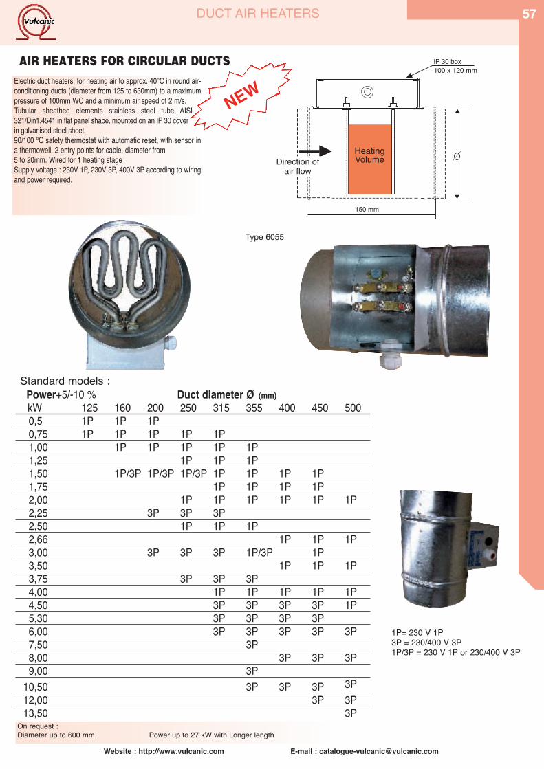
Website : http://www.vulcanic.com E-mail : [email protected]
57DUCT AIR HEATERS
IP 30 box
Direction ofair flow
HeatingVolume
150 mm
100 x 120 mmAIR HEATERS FOR CIRCULAR DUCTS
Electric duct heaters, for heating air to approx. 40°C in round air-conditioning ducts (diameter from 125 to 630mm) to a maximumpressure of 100mm WC and a minimum air speed of 2 m/s.Tubular sheathed elements stainless steel tube AISI321/Din1.4541 in flat panel shape, mounted on an IP 30 coverin galvanised steel sheet. 90/100 °C safety thermostat with automatic reset, with sensor ina thermowell. 2 entry points for cable, diameter from5 to 20mm. Wired for 1 heating stageSupply voltage : 230V 1P, 230V 3P, 400V 3P according to wiringand power required.
Type 6055
NEW
Power+5/-10 % Duct diameter Ø (mm)kW 125 160 200 250 315 355 400 450 5000,5 1P 1P 1P0,75 1P 1P 1P 1P 1P1,00 1P 1P 1P 1P 1P1,25 1P 1P 1P1,50 1P/3P 1P/3P 1P/3P 1P 1P 1P 1P1,75 1P 1P 1P 1P2,00 1P 1P 1P 1P 1P 1P2,25 3P 3P 3P2,50 1P 1P 1P2,66 1P 1P 1P3,00 3P 3P 3P 1P/3P 1P3,50 1P 1P 1P3,75 3P 3P 3P4,00 1P 1P 1P 1P 1P4,50 3P 3P 3P 3P 1P5,30 3P 3P 3P 3P6,00 3P 3P 3P 3P 3P7,50 3P8,00 3P 3P 3P9,00 3P
10,50 3P 3P 3P 3P12,00 3P 3P13,50 3P
Standard models :
1P= 230 V 1P3P = 230/400 V 3P1P/3P = 230 V 1P or 230/400 V 3P
On request : Diameter up to 600 mm Power up to 27 kW with Longer length
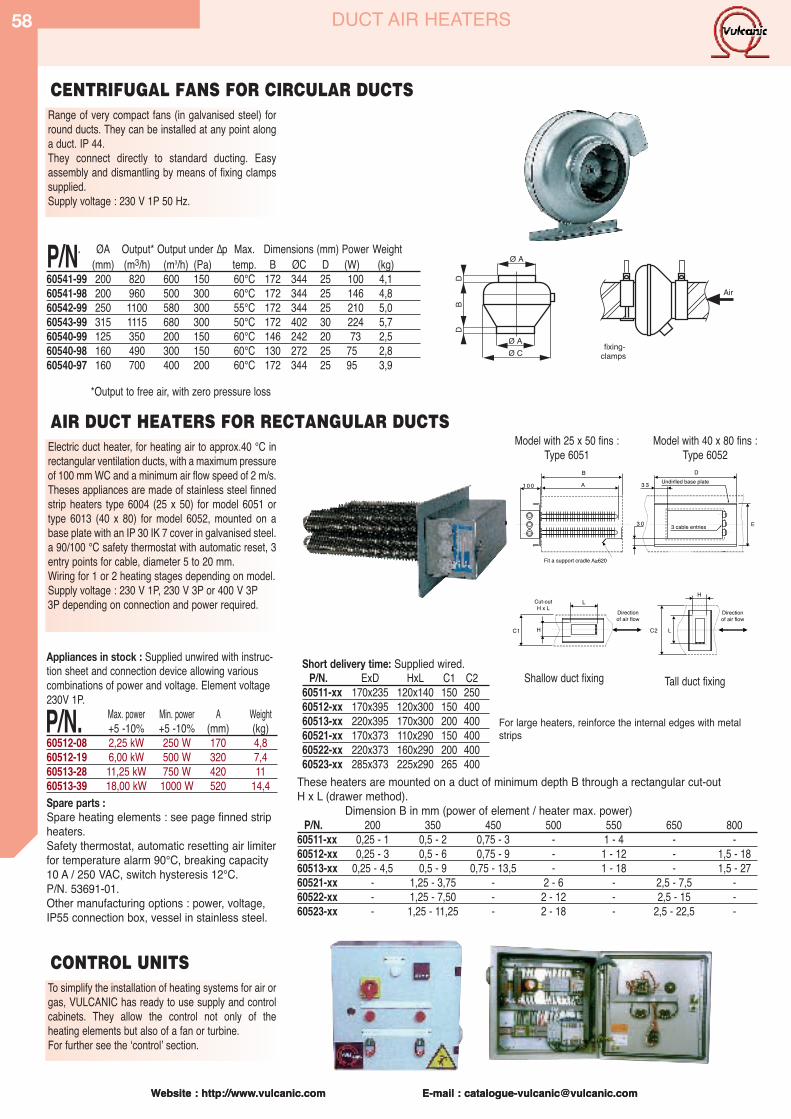
Website : http://www.vulcanic.com E-mail : [email protected]
58
Website : http://www.vulcanic.com E-mail : [email protected]
DUCT AIR HEATERS
Electric duct heater, for heating air to approx.40 °C inrectangular ventilation ducts, with a maximum pressureof 100 mm WC and a minimum air flow speed of 2 m/s.Theses appliances are made of stainless steel finnedstrip heaters type 6004 (25 x 50) for model 6051 ortype 6013 (40 x 80) for model 6052, mounted on abase plate with an IP 30 IK 7 cover in galvanised steel.a 90/100 °C safety thermostat with automatic reset, 3entry points for cable, diameter 5 to 20 mm.Wiring for 1 or 2 heating stages depending on model.Supply voltage : 230 V 1P, 230 V 3P or 400 V 3P3P depending on connection and power required.
Appliances in stock : Supplied unwired with instruc-tion sheet and connection device allowing variouscombinations of power and voltage. Element voltage230V 1P.
P/N. Max. power Min. power A Weight+5 -10% +5 -10% (mm) (kg)
60512-08 2,25 kW 250 W 170 4,860512-19 6,00 kW 500 W 320 7,460513-28 11,25 kW 750 W 420 1160513-39 18,00 kW 1000 W 520 14,4Spare parts :Spare heating elements : see page finned stripheaters.Safety thermostat, automatic resetting air limiterfor temperature alarm 90°C, breaking capacity10 A / 250 VAC, switch hysteresis 12°C.P/N. 53691-01.Other manufacturing options : power, voltage,IP55 connection box, vessel in stainless steel.
Short delivery time: Supplied wired. P/N. ExD HxL C1 C2
60511-xx 170x235 120x140 150 25060512-xx 170x395 120x300 150 40060513-xx 220x395 170x300 200 40060521-xx 170x373 110x290 150 40060522-xx 220x373 160x290 200 40060523-xx 285x373 225x290 265 400
These heaters are mounted on a duct of minimum depth B through a rectangular cut-outH x L (drawer method).
Dimension B in mm (power of element / heater max. power)P/N. 200 350 450 500 550 650 800
60511-xx 0,25 - 1 0,5 - 2 0,75 - 3 - 1 - 4 - -60512-xx 0,25 - 3 0,5 - 6 0,75 - 9 - 1 - 12 - 1,5 - 1860513-xx 0,25 - 4,5 0,5 - 9 0,75 - 13,5 - 1 - 18 - 1,5 - 2760521-xx - 1,25 - 3,75 - 2 - 6 - 2,5 - 7,5 -60522-xx - 1,25 - 7,50 - 2 - 12 - 2,5 - 15 -60523-xx - 1,25 - 11,25 - 2 - 18 - 2,5 - 22,5 -
To simplify the installation of heating systems for air orgas, VULCANIC has ready to use supply and controlcabinets. They allow the control not only of the heating elements but also of a fan or turbine.For further see the ʻcontrolʼ section.
CONTROL UNITS
Model with 25 x 50 fins :Type 6051
Model with 40 x 80 fins :Type 6052
AIR DUCT HEATERS FOR RECTANGULAR DUCTS
Shallow duct fixing Tall duct fixing
For large heaters, reinforce the internal edges with metalstrips
Range of very compact fans (in galvanised steel) forround ducts. They can be installed at any point alonga duct. IP 44.They connect directly to standard ducting. Easyassembly and dismantling by means of fixing clampssupplied.Supply voltage : 230 V 1P 50 Hz.
Air
fixing-clamps
CENTRIFUGAL FANS FOR CIRCULAR DUCTS
*Output to free air, with zero pressure loss
P/N. ØA Output* Output under Δp Max. Dimensions (mm) Power Weight(mm) (m3/h) (m3/h) (Pa) temp. B ØC D (W) (kg)
60541-99 200 820 600 150 60°C 172 344 25 100 4,160541-98 200 960 500 300 60°C 172 344 25 146 4,860542-99 250 1100 580 300 55°C 172 344 25 210 5,060543-99 315 1115 680 300 50°C 172 402 30 224 5,760540-99 125 350 200 150 60°C 146 242 20 73 2,560540-98 160 490 300 150 60°C 130 272 25 75 2,860540-97 160 700 400 200 60°C 172 344 25 95 3,9
Ø A
Ø AØ C
DB
D
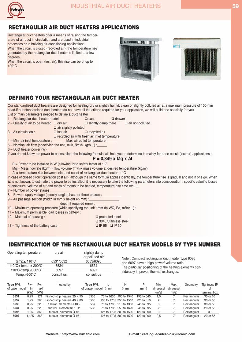
Website : http://www.vulcanic.com E-mail : [email protected]
59INDUSTRIAL AIR DUCT HEATERS
Rectangular duct heaters offer a means of raising the temper-ature of air duct in circulation and are used in industrialprocesses or in building air-conditioning applications.When the circuit is closed (recycled air), the temperature risegenerated by the rectangular duct heater is limited to a fewdegrees.When the circuit is open (lost air), this rise can be of up to400°C.
Our standardised duct heaters are designed for heating dry or slightly humid, clean or slightly polluted air at a maximum pressure of 100 mmhead.If our standardised duct heaters do not have all the criteria required for your application, we will build one specially for you.List of main parameters needed to define a duct heater1 – Rectangular duct heater model � case � drawer2 – Quality of air to be heated � dry air � slightly damp there � air not polluted
� air slightly polluted3 – Air circulation : � lost air � recycled air
� recycled air with fresh air inlet temperature4 – Min. air inlet temperature : Maxi air outlet temperature : 5 – Nominal air flow (specifying the unit, m3/h, Nm3/h, kg/h…) : 6 – Duct heater power (W) : If you do not know the power to be installed, the following formula will help you to determine it, mainly for open circuit (lost air) applications :
P = 0,349 x Mq x ΔtP = Power to be installed in W (allowing for a safety factor of 1,2)Mq = Mass flowrate (kg/h) = flow volume (m3/h)x mass volume at desired temperature (kg/m3)Δt = temperature rise between inlet and outlet of rectangular duct heater in °C
In case of closed circuit operation (lost air), although the same formula applies identically, the temperature rise is gradual and not in one go. WhenΔt is not known, to estimate the power to be installed, it is necessary to take the following parameters into consideration : specific calorific lossesof enclosure, volume of air and mass of rooms to be heated, temperature rise time etc. ...7 – Number of power stages : 8 – Power supply voltage (specify single phase or three phase) : 9 – Air passage section (Width in mm x height en mm) :
depth if required (mm) : 10 – Maximum operating pressure (while specifying the unit : mm de WC, Pa, mBar…) :11 – Maximum permissible load losses in battery :12 – Material of housing : � protected steel
� 304L Stainless steel 13 – Tightness of the battery case : � IP 55 � IP 30
RECTANGULAR AIR DUCT HEATERS APPLICATIONS
DEFINING YOUR RECTANGULAR AIR DUCT HEATER
Operating temperature dry air slightly dampor polluted air
temp.≤ 110°C 6531/6532 6533/6096110°C< temp. ≤ 200°C 6534 6534110°C<temp.≤300°C 6097 6097
Temp.>300°C consult us consult us
Type P/N. Pwr Pwr heated by Type P/N. L H P Min. Max. Geometry Tightness IPof case model min maxi of drawer model (mm) (mm) (mm) air vessel air vessel of
(kW) (kW) (m/s) (m/s) terminal box6531 0,25 171 Finned strip heaters 25 X 50 6535 75 to 1635 190 to 1540 195 to 645 1,5 7 Rectangular 30 or 556532 1,25 285 Finned strip heaters 40 X 80 6536 130 to 1755 350 to 1510 225 to 810 2 7 Rectangular 30 or 556533 0,25 228 tubular elements Ø 10,2 6537 75 to 1795 210 to 1300 245 to 895 3 7 Rectangular 30 or 556534 0,25 228 tubular elementsØ 10,2 6538 75 to 1795 250 to 1620 245 to 895 2 7 Rectangular 20 or 556096 1,35 368 tubular elements Ø 16 - 125 to 1725 500 to 1500 120 to 900 3 7 Rectangular 306097 1,125 368 tubular elements Ø 16 - 125 to 1725 500 to 1500 120 to 900 2,5 7 Rectangular 20 or 55
IDENTIFICATION OF THE RECTANGULAR DUCT HEATER MODELS BY TYPE NUMBER
Note : Compact rectangular duct heater type 6096and 6097 have a high-power/ volume ratio. The particular positioning of the heating elements con-siderably improves thermal exchanges.
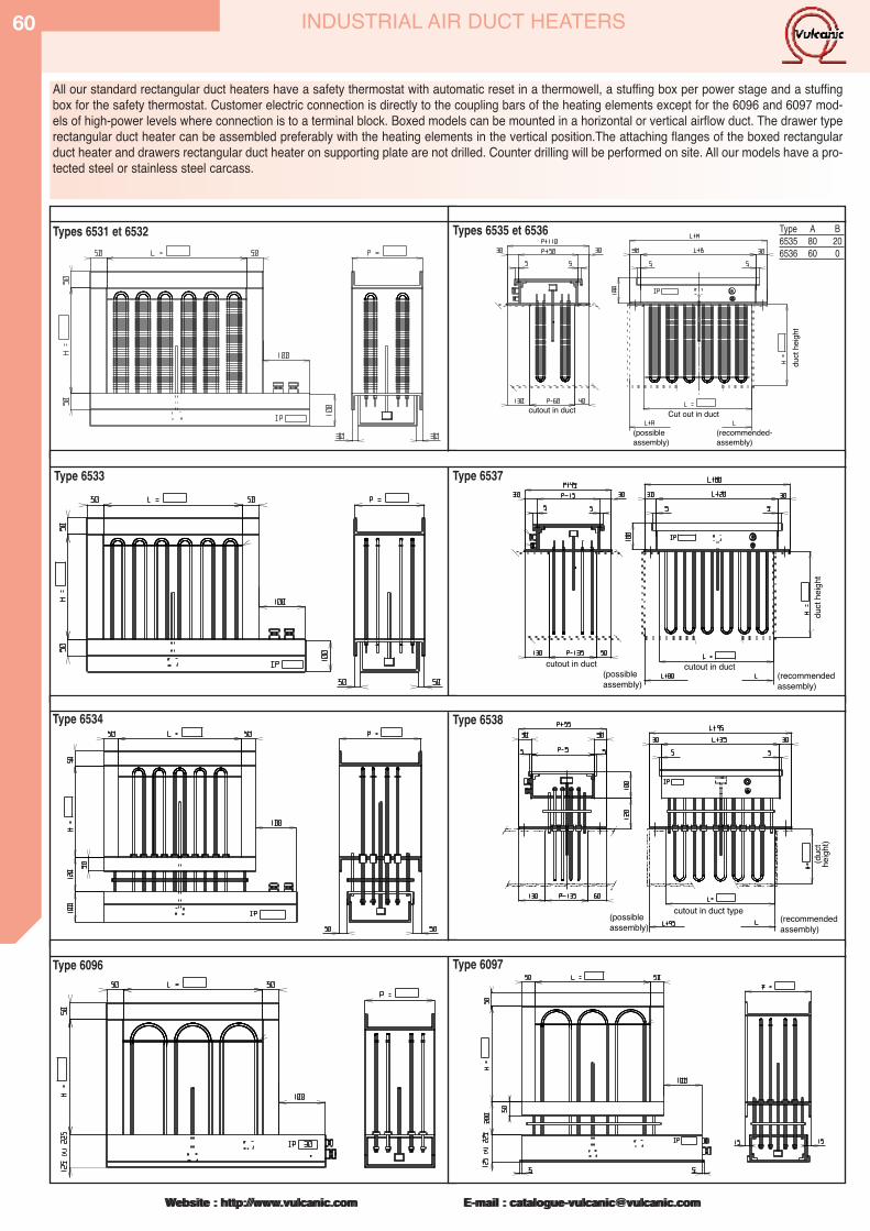
Website : http://www.vulcanic.com E-mail : [email protected]
60
Website : http://www.vulcanic.com E-mail : [email protected]
INDUSTRIAL AIR DUCT HEATERS
All our standard rectangular duct heaters have a safety thermostat with automatic reset in a thermowell, a stuffing box per power stage and a stuffingbox for the safety thermostat. Customer electric connection is directly to the coupling bars of the heating elements except for the 6096 and 6097 mod-els of high-power levels where connection is to a terminal block. Boxed models can be mounted in a horizontal or vertical airflow duct. The drawer typerectangular duct heater can be assembled preferably with the heating elements in the vertical position.The attaching flanges of the boxed rectangularduct heater and drawers rectangular duct heater on supporting plate are not drilled. Counter drilling will be performed on site. All our models have a pro-tected steel or stainless steel carcass.
Cut out in duct
(possibleassembly)
(recommended-assembly)
cutout in duct
duct
heigh
t
cutout in duct(possibleassembly)
(recommended assembly)
cutout in duct
duct
heigh
t
cutout in duct type (possibleassembly)
(recommendedassembly)
(duc
the
ight)
Type A B6535 80 206536 60 0
Types 6535 et 6536
Type 6533 Type 6537
Type 6534 Type 6538
Type 6096 Type 6097
Types 6531 et 6532
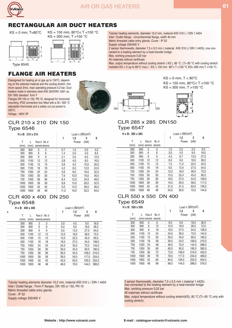
Website : http://www.vulcanic.com E-mail : [email protected]
61AIR OR GAS HEATERS
LTDN DN
H
KS
H x B: 210 x 210 Load n (W/cm2)1 1,5 3 6
T L Rows of Nbr. of Power (kW)(mm) (mm) elements elements300 900 3 3 0,7 1,0 2,0 4,0300 900 6 6 1,4 2,0 4,0 8,0300 900 9 9 2,1 3,0 6,0 12,0500 1100 12 12 2,8 4,0 8,0 16,0500 1100 15 15 3,8 5,0 10,0 20,0500 1100 18 18 4,2 6,0 12,0 24,0750 1350 24 24 5,6 8,0 16,0 32,0750 1350 30 30 7,6 10,0 16,0 40,0750 1350 36 36 8,4 12,0 24,0 48,01000 1600 39 39 8,8 13,0 26,0 52,01000 1600 42 42 9,5 14,0 28,0 56,01000 1600 48 48 11,2 16,0 32,0 64,0
CLR 210 x 210 DN 150Type 6546
CLR 285 x 285 DN150Type 6547
CLR 400 x 400 DN 250Type 6548
CLR 550 x 550 DN 400Type 6549
H x B: 285 x 285 Load n (W/cm2)1 1,5 3 6
T L Rows of Nbr. of Power (kW)(mm) (mm) elements elements300 900 3 3 1,5 2,2 2,5 9,0300 900 6 6 3,0 4,5 9,0 18,0300 900 9 9 4,5 6,7 13,5 27,0500 1100 12 12 6,0 9,0 18,0 36,0500 1100 15 15 7,5 11,2 22,5 45,0500 1100 18 18 9,0 13,4 27,0 54,0750 1350 24 24 12,0 18,0 36,0 72,0750 1350 30 30 15,0 22,4 45,0 90,0750 1350 36 36 18,0 27,0 54,0 108,01000 1600 39 39 19,5 29,0 58,0 117,01000 1600 42 42 21,0 31,5 63,0 126,01000 1600 48 48 24,0 36,0 72,0 144,0
. H x B: 400 x 400 Load n (W/cm2)1 1,5 3 6
T L Rows of Nbr. of Power (kW)(mm) (mm) elements elements300 900 3 3 3,0 4,5 9,0 18,0300 900 6 6 6,0 9,0 18,0 36,0300 900 9 9 9,0 13,5 27,0 54,0500 1100 12 12 12,0 18,0 36,0 72,0500 1100 15 15 15,0 22,5 45,0 90,0500 1100 18 18 18,0 27,0 54,0 108,0750 1350 24 24 24,0 35,0 72,0 144,0750 1350 30 30 30,0 45,0 90,0 180,0750 1350 36 36 36,0 54,0 108,0 216,01000 1600 39 39 39,0 59,0 117,0 234,01000 1600 42 42 42,0 63,0 126,0 252,01000 1600 48 48 48,0 70,0 144,0 288,0
H x B: 550 x 550 Load n (W/cm2)1 1,5 3 6
T L Rows of Nbr. of Power (kW)(mm) (mm) elements elements300 900 3 6 6,0 9,0 18,0 36,0300 900 6 12 12,0 18,0 36,0 72,0300 900 9 18 18,0 27,0 54,0 108,0500 1100 12 24 24,0 36,0 72,0 144,0500 1100 15 30 30,0 45,0 90,0 180,0500 1100 18 36 36,0 54,0 108,0 216,0750 1350 24 48 48,0 72,0 144,0 288,0750 1350 30 60 60,0 90,0 180,0 360,0750 1350 36 72 72,0 108,0 216,0 432,01000 1600 39 78 78,0 117,0 234,0 468,01000 1600 42 84 84,0 126,0 252,0 504,01000 1600 48 96 96,0 144,0 288,0 576,0
Tubular heating elements diameter 10,2 mm, material AISI 316 L / DIN 1.4404Inlet / Outlet flange : Form F flanges, DN 100 or 150, PN 10Metric threaded cable entry glands.Cover : IP 52Supply voltage 230/400 V
KS = 0 mm, T < 80°CKS = 150 mm, 80°C< T <150 °CKS = 300 mm, T >150 °C
Tubular heating elements, diameter 10,2 mm, material AISI 316 L / DIN 1.4404Inlet / Outlet flange : circumferential flange, width 40 mmMetric threaded cable entry glands, Cover : IP 52Supply voltage 230/400 V2 sensor thermowells, diameter 7,5 x 0,5 mm ( material AISI 316 L/ DIN 1.4435), one con-nected to a heating element by a heat-transfer bridgeMax. working pressure 0,02 barAll materials without certificateMax. output temperature without cooling stretch ( KS ), 80 °C. (T> 80 °C with cooling stretchinstalled KS = 0 up to 80°C max.) ; KS = 150 mm 80°< T <150 °C KS= 300 mm,T >150 °C.
KS = 0 mm, T<80°C KS = 150 mm, 80°C< T <150 °CKS = 300 mm, T >150 °C
Designed for heating air or gas up to 150°C, depend-ing on the selected material and the cooling stretch, min-imum speed 3m/s, maxi operating pressure 0,2 bar. Ductheaters made in stainless steel AISI 304/DIN1.4301 asEN 1092 standard form FFlanges DN 100 or 150, PN 10, designed for horizontalmounting. IP52 connection box fitted with a 30 / 300 °Cadjustable thermostat and a safety cut out preset to500°C.Voltage : 400V 3P
FLANGE AIR HEATERS
RECTANGULAR AIR DUCT HEATERS
Type 6545
2 sensor thermowells, diameter 7,5 x 0,5 mm ( material 1.4435),one connected to the heating element by a heat-transfer bridgeMax. working pressure 0,02 barAll materials without certificateMax. output temperature without cooling stretch(KS), 80 °C (T> 80 °C only withcooling stretch).
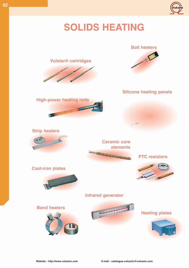
Website : http://www.vulcanic.com E-mail : [email protected]
62
Vulstar® cartridges
Silicone heating panels
Heating plates
Cast-iron plates
Infrared generator
High-power heating rods
Ceramic coreelements
Bolt heaters
SOLIDS HEATING
Strip heaters
PTC resistors
Band heaters
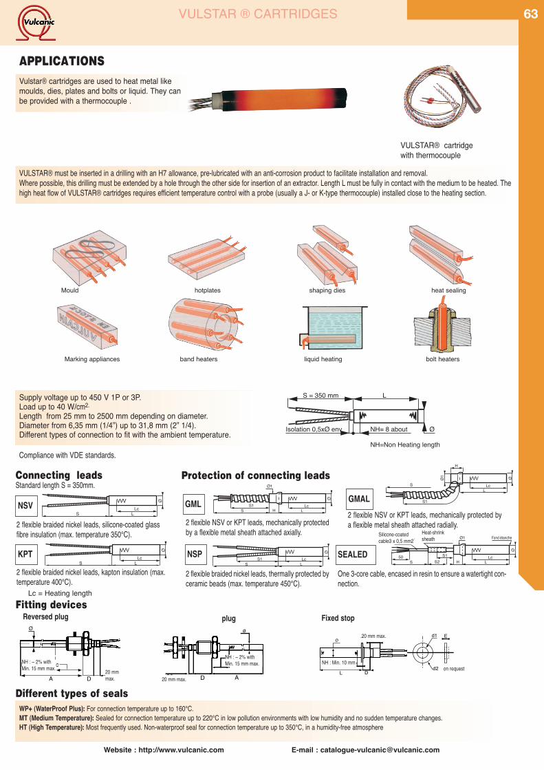
Nc : ± 2% avecmini 15 mm
AD20 mm maximini 15 mm
Nc:± 2 % avec
A D20 mmmaxi
Website : http://www.vulcanic.com E-mail : [email protected]
63VULSTAR ® CARTRIDGES
Vulstar® cartridges are used to heat metal likemoulds, dies, plates and bolts or liquid. They canbe provided with a thermocouple .
Compliance with VDE standards.
APPLICATIONS
2 flexible braided nickel leads, silicone-coated glassfibre insulation (max. temperature 350°C).
2 flexible braided nickel leads, kapton insulation (max.temperature 400°C).
2 flexible braided nickel leads, thermally protected byceramic beads (max. temperature 450°C).
2 flexible NSV or KPT leads, mechanically protectedby a flexible metal sheath attached axially.
2 flexible NSV or KPT leads, mechanically protected bya flexible metal sheath attached radially.
NSV
KPT
GMALGML
One 3-core cable, encased in resin to ensure a watertight con-nection.
SEALEDNSP
WP+ (WaterProof Plus): For connection temperature up to 160°C.MT (Medium Temperature): Sealed for connection temperature up to 220°C in low pollution environments with low humidity and no sudden temperature changes.HT (High Temperature): Most frequently used. Non-waterproof seal for connection temperature up to 350°C, in a humidity-free atmosphere
Different types of seals
Fitting devices
Supply voltage up to 450 V 1P or 3P.Load up to 40 W/cm2.Length from 25 mm to 2500 mm depending on diameter.Diameter from 6,35 mm (1/4”) up to 31,8 mm (2” 1/4).Different types of connection to fit with the ambient temperature.
Mould hotplates shaping dies heat sealing
Marking appliances band heaters liquid heating bolt heaters
VULSTAR® cartridgewith thermocouple
Protection of connecting leadsConnecting leadsStandard length S = 350mm.
NH : – 2% withMin. 15 mm max.
NH : – 2% withMin. 15 mm max.
VULSTAR® must be inserted in a drilling with an H7 allowance, pre-lubricated with an anti-corrosion product to facilitate installation and removal.Where possible, this drilling must be extended by a hole through the other side for insertion of an extractor. Length L must be fully in contact with the medium to be heated. Thehigh heat flow of VULSTAR® cartridges requires efficient temperature control with a probe (usually a J- or K-type thermocouple) installed close to the heating section.
Fixed stop
VVVLc
LS
Ø
H
S1
SVVV
LcL
ØØ1
VVVLc
LS
Ø VVVLcS1
LS
Ø
S1S H
VVVLc
L
Ø
Ø1
50S2
Gaine thermofusibleC�ble silicone3 x 0,5 mm2
S H
VVVS1 Lc
L
¯
¯1 Fond �tanche
20 mm maxi d1
L
Nc mini = 10 mm
Dd2
E
S = 350 mm L
Isolation 0,5xØ env NH= 8 about
NH=Non Heating length
Ø
Silicone-coatedcable3 x 0,5 mm2
Heat-shrinksheath
plug
20 mm max.
Reversed plug
20 mmmax.
NH : Min. 10 mm
.20 mm max.
on request
Lc = Heating length
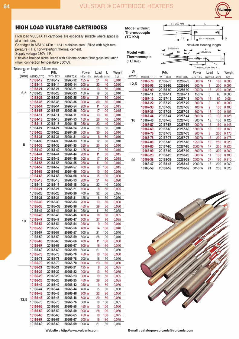
Website : http://www.vulcanic.com E-mail : [email protected]
64 VULSTAR ® CARTRIDGE HEATERS
Ø(mm)
6,5
8
10
12,5
Ø(mm)
12,5
20
P/N. Power Load L WeightWITHOUT TC WITH TC/J WITH TC/K +5% -10% (W/cm2) (mm) (kg)10166-78 20166-78 20266-78 800 W 14 160 0,08510166-96 20166-96 20266-96 600 W 8 200 0,09510166-90 20166-90 20266-90 1250 W 17 200 0,09510167-11 20167-11 20267-11 150 W 6 60 0,06510167-13 20167-13 20267-13 400 W 16 60 0,0610167-22 20167-22 20267-22 300 W 9 80 0,08010167-33 20167-33 20267-33 400 W 9 100 0,10510167-36 20167-36 20267-36 800 W 18 100 0,10510167-44 20167-44 20267-44 600 W 10 130 0,12510167-46 20167-46 20267-46 800 W 13 130 0,12510167-57 20167-57 20267-57 1000 W 13 160 0,14510167-69 20167-69 20267-69 1500 W 18 180 0,16010167-76 20167-76 20267-76 800 W 8 200 0,17510167-78 20167-78 20267-78 1250 W 13 200 0,17510167-88 20167-88 20267-88 1250 W 10 250 0,22010167-80 20167-80 20267-80 2000 W 17 250 0,22010167-99 20167-99 20267-99 1500 W 10 300 0,26010168-23 20168-23 20268-23 800 W 11 130 0,18010168-38 20168-38 20268-38 2500 W 27 160 0,21010168-47 20168-47 20268-47 2000 W 17 200 0,26010168-59 20168-59 20268-59 3150 W 21 250 0,320
P/N. Power Load L WeightWITHOUT TC WITH TC/J WITH TC/K +5% -10% (W/cm2) (mm) (kg)10163-12 20163-12 20263-12 125 W 21 40 0,01010163-14 20163-14 20263-14 200 W 33 40 0,01010163-21 20163-21 20263-21 100 W 13 50 0,01010163-23 20163-23 20263-23 150 W 19 50 0,01010163-25 20163-25 20263-25 250 W 31 50 0,01010163-36 20163-36 20263-36 300 W 30 60 0,01010163-54 20163-54 20263-54 200 W 11 100 0,01510163-56 20163-56 20263-56 300 W 17 100 0,01510164-11 20164-11 20264-11 100 W 13 40 0,01010164-13 20164-13 20264-13 150 W 20 40 0,01010164-15 20164-15 20264-15 250 W 33 40 0,01010164-24 20164-24 20264-24 200 W 20 50 0,01010164-26 20164-26 20264-26 300 W 30 50 0,01010164-31 20164-31 20264-31 100 W 8 60 0,01010164-33 20164-33 20264-33 150 W 12 60 0,01010164-35 20164-35 20264-35 250 W 20 60 0,01010164-42 20164-42 20264-42 125 W 7 80 0,01510164-44 20164-44 20264-44 200 W 11 80 0,01510164-46 20164-46 20264-46 300 W 17 80 0,01510164-55 20164-55 20264-55 250 W 11 100 0,01510164-57 20164-57 20264-57 400 W 18 100 0,01510164-66 20164-66 20264-66 300 W 10 130 0,03010164-68 20164-68 20264-68 450 W 15 130 0,03010165-13 20165-13 20265-13 200 W 21 40 0,02010165-15 20165-15 20265-15 300 W 32 40 0,02010165-21 20165-21 20265-21 100 W 8 50 0,02510165-26 20165-26 20265-26 400 W 32 50 0,02510165-31 20165-31 20265-31 125 W 8 60 0,03010165-33 20165-33 20265-33 200 W 13 60 0,03010165-36 20165--36 20265-36 450 W 29 60 0,03010165-44 20165-44 20265-44 250 W 11 80 0,03510165-46 20165-46 20265-46 400 W 18 80 0,03510165-47 20165-47 20265-47 600 W 27 80 0,03510165-54 20165-54 20265-54 250 W 9 100 0,04010165-56 20165-56 20265-56 400 W 14 100 0,04010165-57 20165-57 20265-57 600 W 21 100 0,04010165-59 20165-59 20265-59 800 W 28 100 0,04010165-66 20165-66 20265-66 400 W 11 130 0,05010165-67 20165-67 20265-67 600 W 16 130 0,05010165-69 20165-69 20265-69 800 W 21 130 0,05010165-76 20165-76 20265-76 450 W 10 160 0,06010165-78 20165-78 20265-78 700 W 16 160 0,06010165-70 20165-70 20265-70 1000 W 23 160 0,06010166-21 20166-21 20266-21 125 W 8 50 0,03510166-22 20166-22 20266-22 200 W 13 50 0,03510166-23 20166-23 20266-23 300 W 19 50 0,03510166-25 20166-25 20266-25 450 W 29 50 0,03510166-42 20166-42 20266-42 250 W 9 80 0,05010166-44 20166-44 20266-44 400 W 15 80 0,05010166-46 20166-46 20266-46 600 W 22 80 0,05010166-48 20166-48 20266-48 800 W 29 80 0,05010166-76 20166-76 20266-76 600 W 10 160 0,08510166-55 20166-55 20266-55 450 W 13 100 0,06010166-59 20166-59 20266-59 1000 W 28 100 0,06010166-65 20166-65 20266-65 450 W 10 130 0,07510166-67 20166-67 20266-67 700 W 15 130 0,07510166-69 20166-69 20266-69 1000 W 21 130 0,075
S = 350 mm L
E NH = 10 about
16
S2 NH=8mm
T
S=350mm L
Thermocouple J ou K
Model withoutThermocouple(TC K/J)
Model withThermocouple(TC K/J)
HIGH LOAD VULSTAR® CARTRIDGESHigh load VULSTAR® cartridges are especially suitable where space isat a minimum.Cartridges in AISI 321/Din 1.4541 stainless steel. Filled with high-tem-perature (HT), non-watertight thermal cement.Supply voltage 230V 1 P.2 flexible braided nickel leads with silicone-coated fiber glass insulation(max. connection temperature 350°C).
Tolerance on length : 2,5 mm min.
NH=Non Heating length
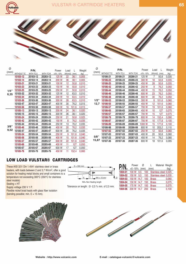
Website : http://www.vulcanic.com E-mail : [email protected]
65VULSTAR ® CARTRIDGE HEATERS
Ø(mm)
1/4”6,35
3/8”9,52
Ø(mm)
1/2”12,7
5/8”15,87
These AISI 321/ Din 1.4541 stainless steel or brassheaters, with loads between 2 and 3,7 W/cm2, offer a goodsolution for heating metal blocks and small containers to atemperature not exceeding 300°C (350°C for stainlesssteel models)Sealing = HTSupply voltage 230 V 1 P.Flexible nickel braid leads with glass fiber isolation(bending possible; min. E = 15 mm).
S = 350 mm L
E ØNH = 10 env
NH= Non Heating length
P/N. Power Load L WeightWITHOUT TC WITH TC/J WITH TC/K +5% -10% (W/cm2) (mm) (kg)10183-12 20183-12 20283-12 125 W 22 38,1 0,00510183-14 20183-14 20283-14 200 W 36 38,1 0,00510183-21 20183-21 20283-21 100 W 12 50,8 0,01010183-23 20183-23 20283-23 150 W 18 50,8 0,01010183-25 20183-25 20283-25 250 W 31 50,8 0,01010183-32 20183-32 20283-32 125 W 12 63,5 0,01010183-34 20183-34 20283-34 200 W 19 63,5 0,01010183-36 20183-36 20283-36 300 W 28 63,5 0,01010183-47 20183-47 20283-47 400 W 30 76,2 0,01510183-56 20183-56 20283-56 300 W 16 101,6 0,01510185-13 20185-13 20285-13 200 W 24 38,1 0,02010185-15 20185-15 20285-15 300 W 36 38,1 0,02010185-24 20185-24 20285-24 250 W 21 50,8 0,02510185-42 20185-42 20285-42 150 W 8 76,2 0,03510185-44 20185-44 20285-44 250 W 13 76,2 0,03510185-46 20185-46 20285-46 400 W 20 76,2 0,03510185-47 20185-47 20285-47 600 W 30 76,2 0,03510185-54 20185-54 20285-54 250 W 9 101,6 0,04010185-56 20185-56 20285-56 400 W 15 101,6 0,04010185-57 20185-57 20285-57 600 W 22 101,6 0,04010185-66 20185-66 20285-66 400 W 11 127 0,05010185-67 20185-67 20285-67 600 W 17 127 0,05010185-76 20185-76 20285-76 450 W 11 152,4 0,060
P/N. Power Load L WeightWITHOUT TC WITH TC/J WITH TC/K +5% -10% (W/cm2) (mm) (kg)10186-21 20186-21 20286-21 125 W 7 50,8 0,03510186-23 20186-23 20286-23 300 W 18 50,8 0,03510186-25 20186-25 20286-25 450 W 28 50,8 0,03510186-42 20186-42 20286-42 250 W 9 76,2 0,05010186-44 20186-44 20286-44 400 W 15 76,2 0,05010186-46 20186-46 20286-46 600 W 23 76,2 0,05010186-48 20186-48 20286-48 800 W 30 76,2 0,05010186-53 20186-53 20286-53 300 W 8 101,6 0,06010186-55 20186-55 20286-55 450 W 12 101,6 0,06010186-57 20186-57 20286-57 700 W 19 101,6 0,06010186-65 20186-65 20286-65 450 W 10 127 0,07510186-67 20186-67 20286-67 700 W 15 127 0,07510186-78 20186-78 20286-78 800 W 14 152,4 0,09010186-87 20186-87 20286-87 700 W 10 177,8 0,10010186-89 20186-89 20286-89 1000 W 15 177,8 0,10010186-98 20186-99 20286-99 800 W 10 203,2 0,11010187-02 20187-02 20287-02 250 W 12 50,8 0,06010187-03 20187-03 20287-03 400 W 20 50,8 0,06010187-23 20187-23 20287-23 450 W 14 76,2 0,08010187-36 20187-36 20287-36 800 W 18 101,6 0,095
P/N. Power Ø L Material Weight+5 -10% (mm) (mm) (kg)
1004-01 100 W 9,5 100 Stainless steel 0,0251004-02 150 W 9,5 150 Stainless steel 0,0351004-03 150 W 14,7 100 Brass 0,0601004-04 150 W 14,7 150 Brass 0,0751004-05 175 W 14,7 150 Brass 0,0751004-06 200 W 14,7 200 Brass 0,100
LOW LOAD VULSTAR® CARTRIDGES
Tolerance on length : 0/ -2,5 % min. of 2,5 mm.

Website : http://www.vulcanic.com E-mail : [email protected]
66 VULSTAR ® CARTRIDGE HEATERS
To heat liquids or solids over great lengths.They are made of AISI 321 /Din 1.4544 or AISI 316L /Din 1.4406 stainless steel tube and loads up to 16 W/cm2.Fixing devices available on request.
P/N. Ø Power (W) Voltage Load L NH Weight(mm) +5/-10% (V) (W/cm2) (mm) (mm) (kg)
1021-11 10 500 230 1 P 5 418 100 0,21021-12 10 1500 400 1 P 5 1055 100 0,41021-13 10 2000 400 1P 5 1374 100 0,51024-11 10 350 230 1P 5 323 100 0,11024-12 10 700 230 1 P 5 546 100 0,21021-21 10,2 500 230 1 P 5 412 100 0,11021-22 10,2 1500 400 1 P 5 1037 100 0,41021-23 10,2 2000 400 1 P 5 1349 100 0,51021-70 12,7 500 230 1 P 5 400 100 0,11021-71 12,7 1000 230 1 P 5 600 100 0,31021-72 12,7 1500 230 1 P 5 1000 100 0,51021-31 15,87 1000 230 1 P 5 501 100 0,41021-32 15,87 2000 230 1 P 5 903 100 0,81021-33 15,87 3000 230 1 P 5 1304 100 1,11021-34 15,87 4000 400 1 P 5 1705 100 1,41021-35 15,87 5000 400 1 P 5 2107 100 1,81024-31 15,87 750 230 1 P 5 401 100 0,31024-32 15,87 1500 230 1 P 5 702 100 0,6
P/N. Ø Power (W) Voltage Load L NH Weight(mm) +5/-10% (V) (W/cm2) (mm) (mm) (kg)
1021-35 15,87 5000 400 1 P 5 2107 100 1,81024-31 15,87 750 230 1 P 5 401 100 0,31024-32 15,87 1500 230 1 P 5 702 100 0,61021-41 16 1000 230 1 P 5 498 100 0,41021-42 16 2000 230 1 P 5 896 100 0,81021-43 16 3000 230 1 P 5 1294 100 1,11021-44 16 4500 400 1 P 5 1891 100 1,61021-45 16 6000 400 1 P 5 2489 100 2,11021-51 20 1000 230 1 P 5 418 100 0,51021-52 20 2000 230 1 P 5 737 100 0,91021-53 20 4000 230 1 P 5 1374 100 1,71021-54 20 4000 230 3 P 13 547 67 0,81021-55 20 4000 400 3 P 13 547 67 0,81021-56 20 6000 230 3 P 20 547 67 0,81021-57 20 6000 400 3 P 20 547 67 0,81021-58 20 7000 230 3 P 23 547 67 0,81021-59 20 7000 400 3 P 23 547 67 0,81024-51 20 1250 230 1 P 5 498 100 0,61024-52 20 2500 230 1 P 5 896 100 1,1
Models listed below are made of AISI 321 / Din 1.4541 tube allowing a surface temperature up to 750°C, with copper braid leads 350 mm, waterproof seals ( con-nection temperature up to 160°C ). They are fitted with J- or K-type thermocouple (diameter 1mm).
EXTRA-LONG VULSTAR® CARTRIDGESS = 350 mm L
Nc
Ø
These cartridges have a very wide range of applica-tions. Their 7 W/cm2 load and their high temperatureresistance (700°C on the sheath surface) allow afast heating of metal blocks and small containers.The connection temperature must not exceed300°C.Sealing = HTSupply voltage 230 V 1 P.Nickel braid leads with glass fiber isolation, length350mmBending possible : min. 40mm
P/N. Power(W) Ø Length L Weight+5 -10% (mm) (mm) (kg)
1008-90 50 W 6,35 50 0,0101008-93 70 W 6,35 70 0,0121008-94 80 W 6,35 80 0,0131008-91 110 W 6,35 100 0,0151007-01 80 W 9,52 50 0,0151007-18 100 W 9,52 60 0,0181007-02 180 W 9,52 100 0,0251007-21 250 W 9,52 120 0,0301007-03 300 W 9,52 150 0,040
P/N. Power(W) Ø Length L Weight+5 -10% (mm) (mm) (kg)
1007-23 180 W 12,7 70 0,0321007-24 220 W 12,7 80 0,0361007-25 320 W 12,7 120 0,0501007-06 380 W 12,7 150 0,0601007-26 550 W 12,7 200 0,0751007-08 320 W 15,87 100 0,0651007-28 400 W 15,87 120 0,0751007-29 650 W 15,87 200 0,1201007-11 1000 W 25,4 200 0,2901007-12 1500 W 25,4 300 0,420
VULSTAR® MEDIUM LOAD CARTRIDGES
Diameter tolerance1021 : ± 0,1 mm1024 : -0,02 / -0,12 mm
For heating liquids by forced convection from -200°Cto 800°C with loads up to 100 W/cm2.These heating rods are generally equipped with athermowell inside the internal tube.AISI 316 L / Din1.4404 or AISI 321 / Din 1;4541stainless steel tube.The tube surface is either smooth or corrugated tooptimise exchange.Outside diameter 19 mm +0,15 /+0.mm.
HIGH POWER HEATING RODS
ON REQUEST
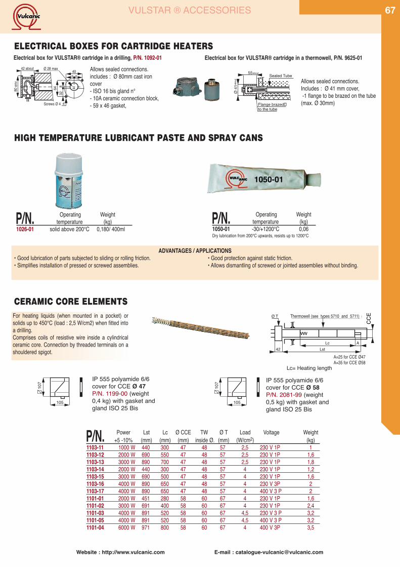
Website : http://www.vulcanic.com E-mail : [email protected]
6780
env
6432
8
42 env Ø 28 maxi
Visserie Ø 4
40= =
Electrical box for VULSTAR® cartridge in a drilling, P/N. 1092-01Allows sealed connections.includes : Ø 80mm cast ironcover- ISO 16 bis gland n°- 10A ceramic connection block,- 59 x 46 gasket,
Electrical box for VULSTAR® cartridge in a thermowell, P/N. 9625-01
Allows sealed connections.Includes : Ø 41 mm cover,-1 flange to be brazed on the tube
(max. Ø 30mm)
55 Sealed Tube
Flange brazed�to the tube
about
abou
t
P/N. Operating Weighttemperature (kg)
1050-01 -30/+1200°C 0,06Dry lubrication from 200°C upwards, resists up to 1200°C
HIGH TEMPERATURE LUBRICANT PASTE AND SPRAY CANS
ADVANTAGES / APPLICATIONS• Good lubrication of parts subjected to sliding or rolling friction. • Good protection against static friction.• Simplifies installation of pressed or screwed assemblies. • Allows dismantling of screwed or jointed assemblies without binding.
VULSTAR ® ACCESSORIES
P/N. Operating Weighttemperature (kg)
1026-01 solid above 200°C 0,180/ 400ml
ELECTRICAL BOXES FOR CARTRIDGE HEATERS
42 about Ø 28 max
Screws Ø 4
For heating liquids (when mounted in a pocket) orsolids up to 450°C (load : 2,5 W/cm2) when fitted intoa drilling.Comprises coils of resistive wire inside a cylindricalceramic core. Connection by threaded terminals on ashouldered spigot.
Doigtde gant (voir types 5710 et 571 1)Ø T
42 LstLc A
ØRS
B
VVV
A=25 pourRSB Ø47A=35 pourRSB Ø58
P/N. Power Lst Lc Ø CCE TW Ø T Load Voltage Weight+5 -10% (mm) (mm) (mm) inside Ø. (mm) (W/cm2) (kg)
1103-11 1000 W 440 300 47 48 57 2,5 230 V 1P 11103-12 2000 W 690 550 47 48 57 2,5 230 V 1P 1,61103-13 3000 W 890 700 47 48 57 2,5 230 V 1P 1,81103-14 2000 W 440 300 47 48 57 4 230 V 1P 1,21103-15 3000 W 690 500 47 48 57 4 230 V 1P 1,61103-16 4000 W 890 650 47 48 57 4 230 V 3P 21103-17 4000 W 890 650 47 48 57 4 400 V 3 P 21101-01 2000 W 451 280 58 60 67 4 230 V 1P 1,61101-02 3000 W 691 400 58 60 67 4 230 V 1P 2,41101-03 4000 W 891 520 58 60 67 4,5 230 V 3 P 3,21101-05 4000 W 891 520 58 60 67 4,5 400 V 3 P 3,21101-04 6000 W 971 800 58 60 67 4 400 V 3P 3,5
CERAMIC CORE ELEMENTSThermowell (see types 5710 and 5711)
A=25 for CCE Ø47A=35 for CCE Ø58
105
107 IP 555 polyamide 6/6
cover for CCE Ø 47P/N. 1199-00 (weight0,4 kg) with gasket andgland ISO 25 Bis
105
107 IP 555 polyamide 6/6
cover for CCE Ø 58P/N. 2081-99 (weight0,5 kg) with gasket andgland ISO 25 Bis
CCE
Lc= Heating length
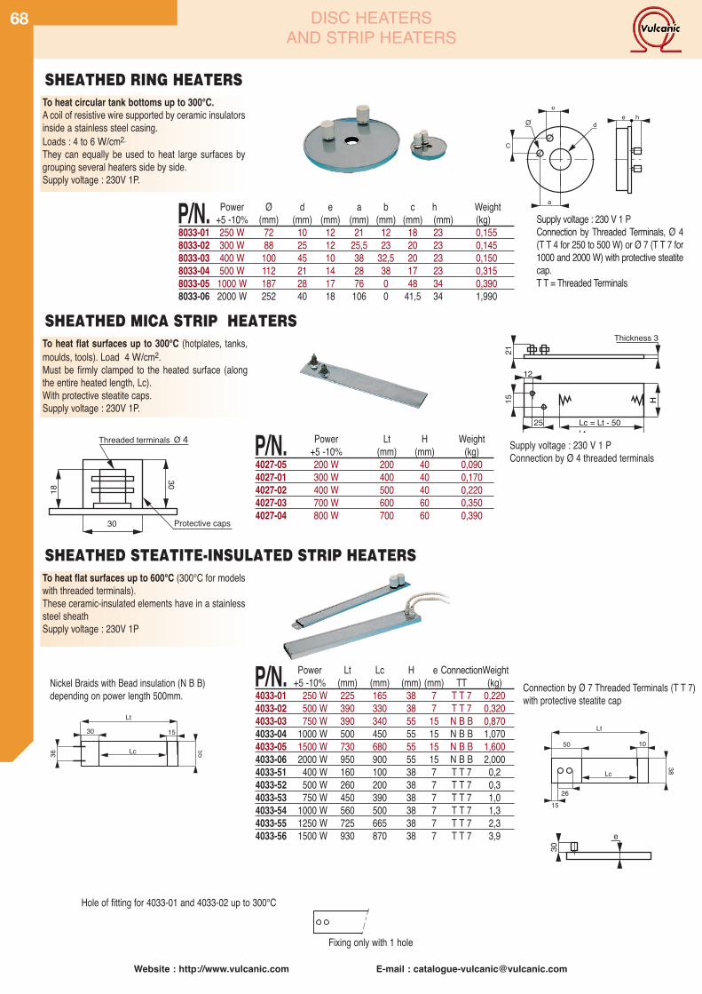
Website : http://www.vulcanic.com E-mail : [email protected]
68
To heat circular tank bottoms up to 300°C.A coil of resistive wire supported by ceramic insulatorsinside a stainless steel casing.Loads : 4 to 6 W/cm2.They can equally be used to heat large surfaces bygrouping several heaters side by side.Supply voltage : 230V 1P.
C
a
b
de h
O
P/N. Power Ø d e a b c h Weight+5 -10% (mm) (mm) (mm) (mm) (mm) (mm) (mm) (kg)
8033-01 250 W 72 10 12 21 12 18 23 0,1558033-02 300 W 88 25 12 25,5 23 20 23 0,1458033-03 400 W 100 45 10 38 32,5 20 23 0,1508033-04 500 W 112 21 14 28 38 17 23 0,3158033-05 1000 W 187 28 17 76 0 48 34 0,3908033-06 2000 W 252 40 18 106 0 41,5 34 1,990
Supply voltage : 230 V 1 PConnection by Threaded Terminals, Ø 4(T T 4 for 250 to 500 W) or Ø 7 (T T 7 for1000 and 2000 W) with protective steatitecap.T T = Threaded Terminals
To heat flat surfaces up to 300°C (hotplates, tanks,moulds, tools). Load 4 W/cm2.Must be firmly clamped to the heated surface (alongthe entire heated length, Lc).With protective steatite caps.Supply voltage : 230V 1P.
P/N. Power Lt H Weight+5 -10% (mm) (mm) (kg)
4027-05 200 W 200 40 0,0904027-01 300 W 400 40 0,1704027-02 400 W 500 40 0,2204027-03 700 W 600 60 0,3504027-04 800 W 700 60 0,390
15
12
H
21
25 Lc = Lt - 50Lt
Thickness 3
Supply voltage : 230 V 1 PConnection by Ø 4 threaded terminals
To heat flat surfaces up to 600°C (300°C for modelswith threaded terminals).These ceramic-insulated elements have in a stainlesssteel sheathSupply voltage : 230V 1P
e
30
P/N. Power Lt Lc H e ConnectionWeight+5 -10% (mm) (mm) (mm) (mm) TT (kg)
4033-01 250 W 225 165 38 7 T T 7 0,2204033-02 500 W 390 330 38 7 T T 7 0,3204033-03 750 W 390 340 55 15 N B B 0,8704033-04 1000 W 500 450 55 15 N B B 1,0704033-05 1500 W 730 680 55 15 N B B 1,6004033-06 2000 W 950 900 55 15 N B B 2,0004033-51 400 W 160 100 38 7 T T 7 0,24033-52 500 W 260 200 38 7 T T 7 0,34033-53 750 W 450 390 38 7 T T 7 1,04033-54 1000 W 560 500 38 7 T T 7 1,34033-55 1250 W 725 665 38 7 T T 7 2,34033-56 1500 W 930 870 38 7 T T 7 3,9
Nickel Braids with Bead insulation (N B B)depending on power length 500mm.
SHEATHED RING HEATERS
SHEATHED MICA STRIP HEATERS
SHEATHED STEATITE-INSULATED STRIP HEATERS
DISC HEATERSAND STRIP HEATERS
18
3030
Threaded terminals 4
Protective caps
O
36
15
55
30
Lc
Lt
Lc
15
38
50
26
10
Lt
Hole of fitting for 4033-01 and 4033-02 up to 300°C
Fixing only with 1 hole
Connection by Ø 7 Threaded Terminals (T T 7)with protective steatite cap
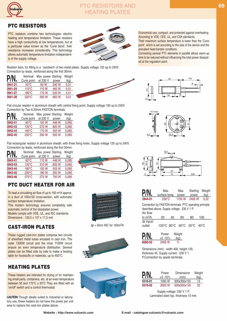
Website : http://www.vulcanic.com E-mail : [email protected]
69
PTC resistors combine two technologies: electricheating and temperature limitation. These resistorshave a high conductivity at low temperatures, but ata particular value known as the ʻCurie bendʼ, theirresistance increases considerably. This technologyallows automatic temperature limitation independent-ly of the supply voltage.
Resistor bare, for fitting in a ʻsandwichʼ of two metal plates. Supply voltage 120 up to 240V.Connection by leads, reinforced along the first 30mm.
593,5
80 100
30
9,5
6
Flat circular resistor in aluminium sheath with central fixing point. Supply voltage 100 up to 240V.Connection by Two 6,35mm FASTON terminals.
95
23,56,2
15 maxi
31
Flat rectangular resistor in aluminium sheath, with three fixing holes. Supply voltage 120 up to 240V.Connection by leads, reinforced along the first 50mm.
34,560 54
5770 2509
2
8,5
To heat a circulating air flow of up to 165 m3/h approx.in a duct of 100x100 cross-section, with automaticsurface temperature limitation.This modern technology ensures completely safeautomatic control of the dissipated power.Models comply with VDE, UL, and IEC standards.Dimensions : 120,5 x 107 x 17,5 mm
Connection by FASTON terminals. PTC operating principledescribed above. Supply voltage : 230 V 1 P.Air flowin m3/h 20 40 60 80 100∆t input/outlet 120°C 80°C 60°C 50°C 40°C
PTC RESISTORS
PTC DUCT HEATER FOR AIR
Dimensions (mm) : width 400, height 120,thickness 45. Supply current : 230 V 1P.Connection by spade terminals.
These heaters are intended for drying or for maintain-ing small parts, containers, etc. at an even temperaturebetween 50 and 170°C ± 20°C They are fitted with anʻon/offʼ switch and a control thermostat.
Supply voltage: 230 V 1 P.Laminated steel top, thickness 10 mm.CAUTION:Though ideally suited to industrial or labora-
tory use, these heaters do not have the power per unitarea to replace the cast-iron plates above.
These rugged cast-iron plates comprise two circuitsof sheathed metal tubes encased in cast iron. Theouter 1300W circuit and the inner 1100W circuitensure an even temperature distribution. Severalplates can be fitted side by side to make a heatingtable for foodstuffs or materials, up to 450°C.
∆p = 8mm WC for 165m3/hCAST-IRON PLATES
HEATING PLATES
P/N. Nominal Max. power Starting WeightCurie point. at 230 V power (kg)
3941-21 50°C 60 W 240 W 0,013941-24 110°C 110 W 460 W 0,013941-27 180°C 170 W 520 W 0,013941-28 220°C 200 W 660 W 0,01
P/N. Nominal Max. power Starting WeightCurie point. at 230 V power (kg)
3942-41 60°C 150 W 448 W 0,0653942-43 120°C 270 W 820 W 0,0653942-44 180°C 170 W 505 W 0,0653942-45 230°C 200 W 550 W 0,065
P/N. Nominal Max. power Starting WeightCurie point. at 230 V power (kg)
3943-41 60°C 110 W 448 W 0,0653943-43 120°C 210 W 820 W 0,0653943-44 180°C 150 W 505 W 0,0653943-45 230°C 180 W 550 W 0,0653943-46 270°C 275 W 700 W 0,065
P/N. Max. Max. Starting Weightsurface temp. power power (kg)
3944-01 230°C 1750 W 2400 W 0,22
P/N. Power Weight+5 -10% (kg)
8560-02 2400 W 11
P/N. Power Dimensions Weight+5 -10% (mm) (kg)
5516-01 1000 W 300x300x155 135516-02 2000 W 500x500x155 32
PTC RESISTORS ANDHEATING PLATES
Economical use, compact, and protected against overheating.According to VDE, CEE, UL, and CSA standards.Their maximum surface temperature is lower than the ʻCuriepointʼ, which is set according to the size of the device and theprevalent heat-transfer conditions.Connecting several PTC elements in parallel allows warm-uptime to be reduced without influencing the total power dissipat-ed at the regulation point.

Website : http://www.vulcanic.com E-mail : [email protected]
70
20
mini 3
Ø to clamp
45°
20
3
15
LStd 1 m
H +- 1
= =
12
Ideally suited for heating cylindrical shapes in dampenvironments, in the presence of fatty matter, moltenplastic, rubber, etc.(350°C maximum). Provided withbrass or stainless profile shielding, brazed connectioncover and clamping device offering compact overalldimensions.Power supply voltage: 230 V 1P.Output is by a flexible metal braid 1 m long protectingthe two power supply conductors with one groundwire.
BAND HEATERS
These collars resolve all heating problems for cylin-drical shapes up to a temperature of 350°C. Theyare loaded to a maximum of 4W/cm2. The heatingelement is enclosed in a sheet metal structure; thefast coupling system allows easy assembly and dis-assembly. Power supply voltage: 230 V 1P. Outputsare by M5 or M7 ( starting from 350 W) threadedterminals.Our technical advice :Taking precautions, it is possible to open Mica col-lars with diameters ≥ 100 mm. This operation mustonly be performed once, taking care not to damagethe heating part. Finalise tightening when the collarreaches its working temperature.They are delivered without caps.
Ø to clamp
24 (BF5)32 (BF7)
H +- 1
Aperture
Ø 16
3
35
MICA BAND HEATERS
P/N. Power Ø Nom.Ø Clamp. H Weight+5 -10% (mm) (mm) (mm) (kg)
4020-07 300 W 63 62 to 67 40 0,1604020-08 350 W 70 74 to 79 40 0,1804020-23 375 W 75 74 to 79 40 0,1904020-09 400 W 80 80 to 86 40 0,2054020-10 450 W 90 88 to 96 40 0,2304020-11 500 W 100 98 to 106 40 0,2554020-12 560 W 110 108 to 117 40 0,2854020-13 575 W 120 118 to 122 40 0,3054020-14 750 W 125 123 to 127 50 0,3604020-15 800 W 130 128 to 137 50 0,3704020-16 850 W 140 138 to 147 50 0,3954020-17 875 W 150 148 to 157 50 0,4204020-18 900 W 160 158 to 167 50 0,4454020-19 1000 W 170 168 to 177 50 0,4604020-20 1100 W 180 178 to 187 50 0,4704020-21 1200 W 190 188 to 197 50 0,4924020-22 1300 W 200 198 to 207 50 0,520
P/N. Power Ø Nom. Ø Clamp. H Weight+5 -10% (mm) (mm) (mm) (kg)
4020-01 120 W 32 31 to 33 30 0,0904020-02 130 W 35 34 to 38 30 0,0954020-03 190 W 40 39 to 43 40 0,1204020-04 210 W 45 44 to 48 40 0,1254020-05 240 W 50 49 to 53 40 0,1304020-06 270 W 56 54 to 60 40 0,140
SEALED MICA BAND HEATERS
P/N. Power. Ø Nom. Ø Clamp. H Weight+5 -10% (mm) (mm) (mm) (kg)
4040-60 100 W 29 28 to 30 25 0,1154040-61 120 W 29 28 to 30 30 0,1204040-62 160 W 29 28 to 30 40 0,1304040-63 135 W 32 31 to 33 30 0,1204040-64 150 W 35 34 to 38 30 0,1254040-65 200 W 35 34 to 38 40 0,1354040-66 140 W 40 39 to 43 25 0,1304040-67 170 W 40 39 to 43 30 0,130
P/N. Power Ø Nom. Ø Clamp. H Weight+5 -10% (mm) (mm) (mm) (kg)
4040-68 225 W 40 39 to 43 40 0,1704040-69 160 W 45 44 to 48 25 0,1304040-70 190 W 45 44 to 48 30 0,1404040-71 225 W 45 44 to 48 40 0,1804040-72 175 W 50 49 to 53 25 0,1354040-73 210 W 50 49 to 53 30 0,1504040-74 280 W 50 49 to 53 40 0,1704040-75 350 W 50 49 to 53 50 0,1904040-76 200 W 56 54 to 61 25 0,1404040-77 235 W 56 54 to 61 30 0,1554040-78 310 W 56 54 to 61 40 0,1954040-79 390 W 56 54 to 61 50 0,2254040-80 260 W 63 62 to 67 30 0,1604040-81 300 W 70 68 to 76 30 0,1704040-82 400 W 70 68 to 76 40 0,2004040-83 450 W 80 77 to 86 40 0,210
Collars allowing the heating of cylindrical shapes upto maximum of 700°C depending on load, consist-ing of a nickel-chrome resistive wire mounted onsteatite elements. These articulated elements makethe assembly particularly flexible.Electrical connection is by threaded terminals.
GENERAL MANUFACTURING CHARACTERISTICSDiameter : all diameters from 90 mm to 3600 mmHeight : 32 - 44 - 55 - 78 mmPower :depending on the exchange surface (specific
load up to 10 W/cm2)Voltage :any voltage up to 400 VCurrent : 4 Min - Max depending on availabilities 60AOutputs :Cover and metal duct up to 300°C
(without external lagging): Threaded terminals Ø. 7 up to 500°C(without external lagging): Threaded terminals Ø. 7 up to 300°C(without external lagging):Nickels beads for high temperatures
Ø tocla
mp
H+- 230
1025
Ø26
17type 4030
Ø tocla
mp
H+- 230
1025
Ø26
17type 4032
ARTICULATED CERAMIC BAND HEATERS
P/N. Power (W) U C/S. Ø H+5 -10% (V) (W/cm2) (mm) (mm)
4030-13 990 230 2 300 554030-14 1350 230 2 410 554030-15 1650 230 2 500 554030-16 2520 230 2 760 554030-22 660 230 4 100 554030-27 990 230 4 150 554030-29 1200 230 4 180 554030-30 1320 230 4 200 554030-31 1530 230 4 230 554030-32 1650 230 4 250 554030-33 1980 230 4 300 554030-34 2700 230 4 410 554030-35 3300 230 4 500 554030-42 990 230 6 100 554030-44 1200 230 6 120 554030-47 1500 230 6 150 554030-49 1770 230 6 180 554030-50 1980 230 6 200 554030-51 2280 230 6 230 554030-52 2490 230 6 250 554030-53 2970 230 6 300 554030-54 4050 230 6 410 554030-55 4950 230 6 500 55
No .Power (W) U C/S. Ø H+5 -10% (V) (W/cm2) (mm) (mm)
4032-10 930 230 2 200 784032-11 1100 230 2 230 784032-12 1170 230 2 250 784032-13 1410 230 2 300 784032-14 1920 230 2 410 784032-15 2340 230 2 500 784032-22 930 230 4 100 784032-24 1120 230 4 120 784032-27 1410 230 4 150 784032-29 1680 230 4 180 784032-30 1860 230 4 200 784032-31 2160 230 4 230 784032-32 2340 230 4 250 784032-33 2820 230 4 300 784032-34 3840 230 4 410 784032-35 4680 230 4 500 784032-42 1410 230 6 100 784032-44 1680 230 6 120 784032-47 2100 230 6 150 784032-49 2520 230 6 180 784032-50 2820 230 6 200 784032-51 3240 230 6 230 784032-52 3510 230 6 250 784032-53 4200 230 6 300 784032-54 5760 230 6 410 784032-55 7020 230 6 500 78
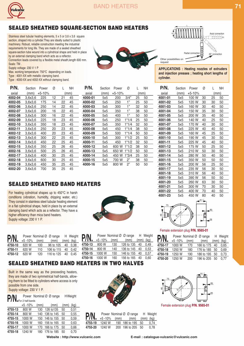
Website : http://www.vulcanic.com E-mail : [email protected]
71
Stainless steel tubular heating elements, 5 x 5 or 3,6 x 3,6 squaresection, shaped into a cylinder.They are ideally suited to plasticmachinery. Robust, reliable construction meeting the industrialrequirements for long life. They are made of a sealed sheathedsquare-section tube wound into a cylindrical shape and held in placeby an external clamping band which acts as a reflector.Connection leads covered by a flexible metal sheath,length 600 mm.Seals: TM .Supply voltage: 230 V 1 PMax. working temperature: 750°C depending on loads.Type : 4001-XX with metallic clamping band.Type : 4000-XX and 4002-XX without clamping band.
APPLICATIONS : Heating nozzles of extrudersand injection presses ; heating short lengths ofcylinder.
Ø
L
Sortie axiale
Sortie à 45°Sortie radiale
P/N. Section Power Ø L NHaxial (mm) +5-10% (mm)
4002-04 3,6x3,6 225 12 21 454002-05 3,6x3,6 175 14 22 454002-06 3,6x3,6 250 14 22 454002-07 3,6x3,6 200 16 22 454002-08 3,6x3,6 300 16 22 454002-09 3,6x3,6 225 18 23 454002-10 3,6x3,6 350 18 23 454002-11 3,6x3,6 250 20 23 454002-12 3,6x3,6 400 20 23 454002-13 3,6x3,6 300 22 25 454002-14 3,6x3,6 450 22 25 454002-15 3,6x3,6 350 25 26 454002-16 3,6x3,6 500 25 26 454002-17 3,6x3,6 400 30 25 454002-18 3,6x3,6 600 30 25 454002-19 3,6x3,6 450 35 25 454002-20 3,6x3,6 700 35 25 45
P/N. Section Power Ø L NHaxial (mm) +5-10% (mm)
4000-01 5x5 200 3/4” 25 504000-02 5x5 250 1” 25 504000-03 5x5 300 1” 32 504000-04 5x5 350 1” 38 504000-05 5x5 400 1” 50 504000-06 5x5 250 1“1/4 25 504000-07 5x5 350 1“1/4 32 504000-08 5x5 450 1“1/4 38 504000-09 5x5 500 1“1/4 50 504000-10 5x5 300 1“1/2 25 504000-11 5x5 450 1“1/2 32 504000-12 5x5 600 W 1“1/2 38 504000-13 5x5 650 W 1“1/2 50 504000-14 5x5 450 W 1“3/4 25 504000-15 5x5 700 W 2” 38 504000-16 5x5 800 W 2” 50 50
P/N. Section Power Ø L NHaxial (mm) +5-10% (mm)
4001-01 5x5 100 W 30 25 504001-02 5x5 120 W 30 30 504001-03 5x5 160 W 30 40 504001-04 5x5 150 W 35 30 504001-05 5x5 200 W 35 40 504001-06 5x5 140 W 40 25 504001-07 5x5 170 W 40 30 504001-08 5x5 225 W 40 40 504001-09 5x5 160 W 45 25 504001-10 5x5 190 W 45 30 504001-11 5x5 225 W 45 40 504001-12 5x5 175 W 50 25 504001-13 5x5 210 W 50 30 504001-14 5x5 280 W 50 40 504001-15 5x5 350 W 50 50 504001-16 5x5 200 W 56 25 504001-17 5x5 235 W 56 30 504001-18 5x5 310 W 56 40 504001-19 5x5 390 W 56 50 504001-20 5x5 260 W 63 30 504001-21 5x5 300 W 70 30 504001-22 5x5 400 W 70 40 504001-23 5x5 450 W 80 40 50
BAND HEATERS
Female extension plug P/N. 9565-01
For heating cylindrical shapes up to 450°C in harshconditions (vibration, humidity, dripping water, etc.)They consist in stainless steel tubular heating elementin a flat cylindrical shape, held in place by an externalclamping band which acts as a reflector. They have ahigher efficiency than mica band heaters.Supply voltage: 230 V 1 P.
46
75
H
8,5
26Ø à serrer
±1
± 1
SEALED SHEATHED BAND HEATERS
P/N. Power Nominal Ø Ø range H Weight+5 -10% (mm) (mm) (mm) (kg)
4750-10 620 W 100 96 to 105 40 0,384750-11 620 W 110 106 to 115 40 0,424750-12 620 W 120 116 to 125 40 0,45
P/N. Power Nominal Ø Ø range H Weight+5 -10% (mm) (mm) (mm) (kg)
4750-13 800 W 130 126 to 135 40 0,494750-14 800 W 140 136 to 145 40 0,534750-15 1000 W 150 146 to 155 40 0,574750-16 1000 W 160 156 to 165 40 0,60
P/N. Power Nominal Ø Ø range H Weight+5 -10% (mm) (mm) (mm) (kg)
4750-17 1000 W 170 166 to 175 40 0,654750-18 1250 W 180 176 to 185 50 0,694750-19 1250 W 190 186 to 195 50 0,734750-20 1250 W 200 196 to 205 50 0,77
Built in the same way as the preceeding heaters,they are made of two symmetrical half-bands, allow-ing them to be fitted to cylinders where access is onlypossible from one side.Supply voltage: 230 V 1 P. 46
75
H
8,5
26Ø à serrer
±1
± 1
P/N. Power Nominal Ø Ø range H Weight+5 -10% (mm) (mm) (mm) (kg)
4755-19 1240 W 190 186 to 195 50 0,744755-20 1240 W 200 196 to 205 50 0,78
P/N. Power Nominal Ø Ø range HWeightFor 2 half-bands
+5 -10% (mm) (mm) (mm) (kg)4755-13 800 W 130 126 to135 50 0,514755-14 800 W 140 136 to 145 50 0,554755-15 1000 W 150 146 to 155 50 0,594755-16 1000 W 160 156 to 165 50 0,634755-17 1000 W 170 166 to 175 50 0,664755-18 1240 W 180 176 to 185 50 0,70
SEALED SHEATHED BAND HEATERS IN TWO HALVES
SEALED SHEATHED SQUARE-SECTION BAND HEATERS
Female extension plug P/N. 9565-01
Radial connection
Axial connection
45° connection
Ø range
Ø range
Other possibilities onrequest
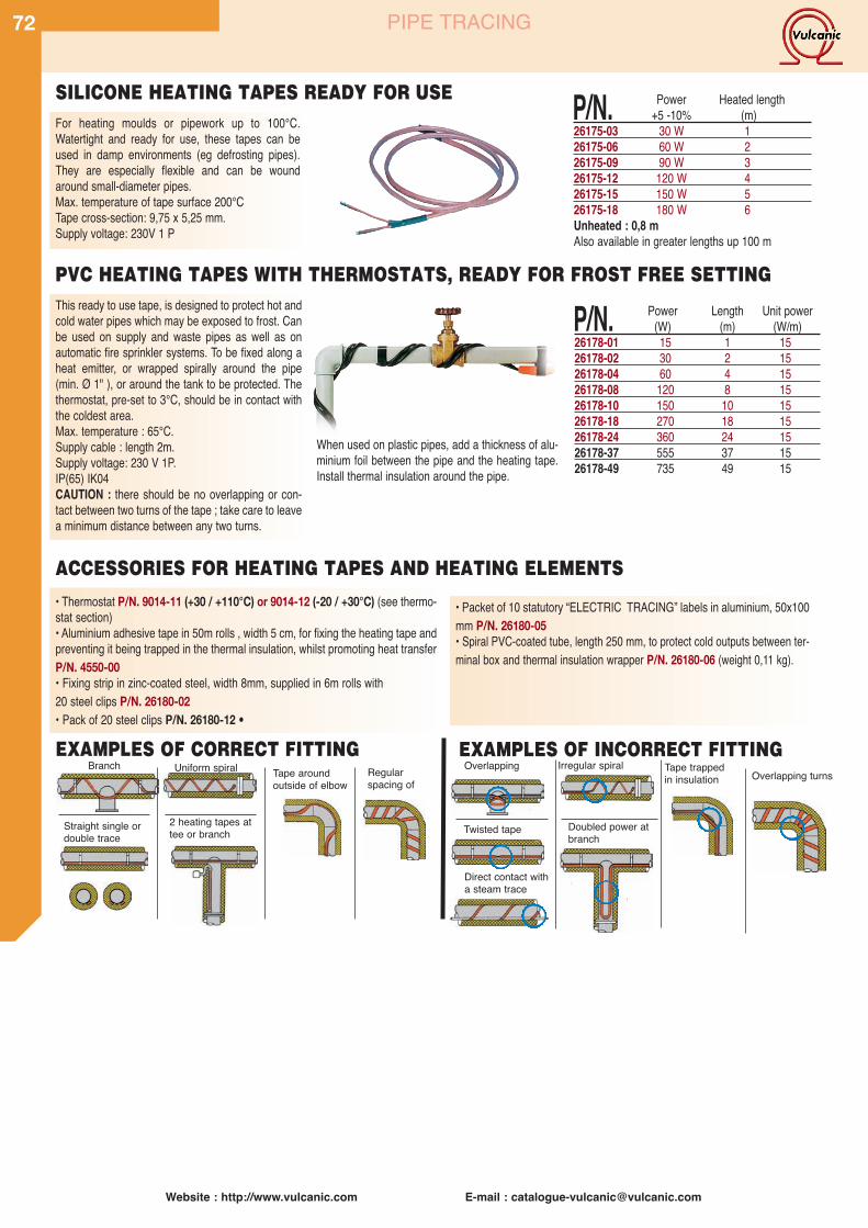
Website : http://www.vulcanic.com E-mail : [email protected]
72 PIPE TRACING
This ready to use tape, is designed to protect hot andcold water pipes which may be exposed to frost. Canbe used on supply and waste pipes as well as onautomatic fire sprinkler systems. To be fixed along aheat emitter, or wrapped spirally around the pipe(min. Ø 1" ), or around the tank to be protected. Thethermostat, pre-set to 3°C, should be in contact withthe coldest area.Max. temperature : 65°C.Supply cable : length 2m.Supply voltage: 230 V 1P.IP(65) IK04CAUTION : there should be no overlapping or con-tact between two turns of the tape ; take care to leavea minimum distance between any two turns.
When used on plastic pipes, add a thickness of alu-minium foil between the pipe and the heating tape.Install thermal insulation around the pipe.
For heating moulds or pipework up to 100°C.Watertight and ready for use, these tapes can beused in damp environments (eg defrosting pipes).They are especially flexible and can be woundaround small-diameter pipes.Max. temperature of tape surface 200°CTape cross-section: 9,75 x 5,25 mm.Supply voltage: 230V 1 P
SILICONE HEATING TAPES READY FOR USE
• Thermostat P/N. 9014-11 (+30 / +110°C) or 9014-12 (-20 / +30°C) (see thermo-stat section)• Aluminium adhesive tape in 50m rolls , width 5 cm, for fixing the heating tape andpreventing it being trapped in the thermal insulation, whilst promoting heat transferP/N. 4550-00• Fixing strip in zinc-coated steel, width 8mm, supplied in 6m rolls with20 steel clips P/N. 26180-02• Pack of 20 steel clips P/N. 26180-12 •
• Packet of 10 statutory “ELECTRIC TRACING” labels in aluminium, 50x100mm P/N. 26180-05• Spiral PVC-coated tube, length 250 mm, to protect cold outputs between ter-minal box and thermal insulation wrapper P/N. 26180-06 (weight 0,11 kg).
P/N. Power Length Unit power(W) (m) (W/m)
26178-01 15 1 1526178-02 30 2 1526178-04 60 4 1526178-08 120 8 1526178-10 150 10 1526178-18 270 18 1526178-24 360 24 1526178-37 555 37 1526178-49 735 49 15
P/N. Power Heated length+5 -10% (m)
26175-03 30 W 126175-06 60 W 226175-09 90 W 326175-12 120 W 426175-15 150 W 526175-18 180 W 6Unheated : 0,8 mAlso available in greater lengths up 100 m
PVC HEATING TAPES WITH THERMOSTATS, READY FOR FROST FREE SETTING
ACCESSORIES FOR HEATING TAPES AND HEATING ELEMENTS
Overlapping turnsTape trappedin insulationTape around
outside of elbowRegularspacing of
Overlapping
Twisted tape
Irregular spiral
2 heating tapes attee or branch
Uniform spiralBranch
Straight single ordouble trace
Doubled power atbranch
EXAMPLES OF CORRECT FITTING
Direct contact witha steam trace
EXAMPLES OF INCORRECT FITTING
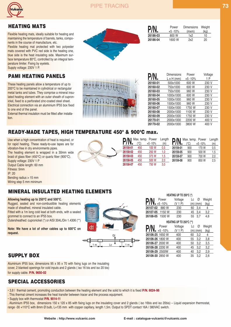
Website : http://www.vulcanic.com E-mail : [email protected]
73PIPE TRACING
Use when a high concentration of heat is required, orfor rapid heating. These ready-to-use tapes are forvibration-free in dry environments pipes.The heating element is wrapped in a 30mm widebraid of glass fiber (450°C) or quartz fiber (900°C).Supply voltage: 230V 1 POutput Cable length: 60 mmFitness: 5mmIP: 20Bending radius > 15 mmWiring step 5 mm minimum
P/N.Max. temp. Power Length(°C) +5 -10% (m)
26158-01 450 100 W 0,526158-02 450 250 W 1,026158-03 450 375 W 1,526158-05 450 500 W 2,026158-07 450 750 W 3,0
P/N. Dimensions Power VoltageL x H (mm) +5 -10% 1 P
26160-01 500x1000 600 W 230 V26160-02 750x1000 600 W 230 V26160-03 750x1000 960 W 230 V26160-04 1000x1000 600 W 230 V26160-05 1000x1000 960 W 230 V26160-06 1500x1000 960 W 230 V26160-07 1500x1000 1750 W 230 V26160-08 2000x1000 1100 W 230 V26160-09 2000x1000 1750 W 230 V26170-01 2000x1000 2200 W 400 V26170-02 2000x1000 3800 W 400 V
These heating panels allow a temperature of up to200°C to be maintained in cylindrical or rectangularmetal tanks and tubes. They comprise a mineral insu-lated heating element with an outer sheath of cupron-ickel, fixed to a perforated zinc-coated steel sheet.Electrical connection via an aluminium IP55 box fixedto one end of the panel.External thermal insulation must be fitted after installa-tion.
Flexible heating mats, ideally suitable for heating andmaintaining the temperature of barrels, tanks, compo-nents in the course of manufacture, etc.Flexible heating mat protected with two polyestermats covered with PVC red side is the heating one,blue side is the heat insulating side. Maximum sur-face temperature 80°C, controlled by an integral tem-perature limiter. Fixing by eyelets.Supply voltage: 230V 1 P.
P/N. Power Dimensions Weight+5 -10% (mxm) (kg)
26186-03 800 W 1x2 1026186-04 1600 W 2x2 20
PAMI HEATING PANELS
HEATING MATS
READY-MADE TAPES, HIGH TEMPERATURE 450° & 900°C max.
P/N.Max. temp. Power Length(°C) +5 -10% (m)
26159-01 900 170 W 0,526159-05 900 500 W 1,526159-07 900 700 W 2,026159-08 900 850 W 2,5
Aluminium IP55 box, dimensions 95 x 95 x 70 with fixing lugs on the insulatingcover, 2 blanked openings for cold inputs and 2 glands ( iso 16 bis and iso 20 bis)for supply cable. P/N. 9650-02
1 m 1 mLc
Ø
HEATING UP TO 250°C (*)
P/N. Power Voltage Lc Ø Weight+5 -10% (V 1 P) (m) (mm) (kg)
26107-02 880 W 230 60 3,4 426107-05 1150 W 230 45 3,4 3,226108-05 1500 W 230 55 3,7 4,6
HEATING UP TO 250°C (**)
P/N. Power Voltage Lc Ø Weight+5 -10% (V 1 P) (m) (mm) (kg)
26106-25 1650 W 400 60 3,2 426106-26 1800 W 400 55 3,2 3,826106-27 2000 W 400 50 3,2 3,526106-28 2200 W 400 45 3,2 3,226106-29 2500W 400 40 3,2 2,926106-30 2850 W 400 35 3,2 2,6
MINERAL INSULATED HEATING ELEMENTS
SUPPLY BOX
• 3,8 l thermal cement, promoting conduction between the heating element and the solid to which it is fixed P/N. 6024-98. This thermal ciment increases the heat transfer between tracer and the process equipment.• Supply box with thermostat P/N. 9014-11. Aluminium IP55 box, dimensions 150 x 120 x 85 with fixing lugs on the insulating cover and 2 glands ( iso 16bis and iso 20bis) – Liquid expansion thermostat,range -30 +110°C with 8mm Ø bulb, L=135 mm with copper capillary, length 1,5m. Output to SPDT contact 16A / 380VAC switch.
SPECIAL ACCESSORIES
Allowing heating up to 250°C and 500°C.Rugged, sealed and non-combustible heating elementsmade of sheathed, mineral insulated cable.Fitted with a 1m long cold lead at both ends, with a sealedgrommet to connect to an IP55 box.Outersheathed: cupronickel (*) or AISI 304L/Din 1.4306 (**)
Note: We have a lot of other cables up to 600°C onrequest.
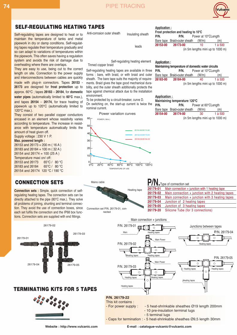
Website : http://www.vulcanic.com E-mail : [email protected]
74 PIPE TRACING
Self-regulating tapes are designed to heat or tomaintain the temperature of tanks and metalpipework in dry or damp conditions. Self-regulat-ing tapes regulate their temperature gradually andso can adapt to variations of temperatures withinthe pipework. This often saves having a regulationsystem and avoids the risk of damage due tooverheating where there are overlaps.They are easy to use, being cut to the correctlength on site. Connection to the power supplyand interconnections between cables are quicklymade with plug-in connectors. Tapes 26153 -26173 are designed for frost protection up toapprox. 60°C ; tapes 26183 – 26184, for domesticwater pipes (automatically limited to 60°C max.),and tapes 26154 – 26174, for trace heating ofpipework up to 120°C (automatically limited to120°C max.).They consist of two parallel copper conductorsencased in an element whose resistivity variesaccording to temperature. The increase in resist-ance with temperature automatically limits theamount of heat given off.Supply voltage : 230 V 1 P.Max. powered length :26153 and 26173 = 200 m ( 16 A )26183 and 26184 = 100 m ( 32 A )26154 and 26174 = 100 (25 A )Temperature maxi on/ off:26153 and 26173 65°C / 80 °C26183 and 26184 65°C / 80 °C26154 and 26174 120 °C / 190 °C
Self-regulating heating tapes are available in threeforms : bare, with braid, or with braid and outersheath. The bare tape suits the majority of require-ments. Braid gives the tape good mechanical dura-bility, and the outer sheath additionally protects thetape against chemical attack due to the installationenvironment.To be protected by a circuit-breaker, curve D.On switching on, the start-up current is twice thenominal current.
Connection sets : Simple, quick connection of self-regulating heating tapes. The connection sets can bedirectly attached to the pipe (80°C max.). They solveall problems of joining, shunting and terminal connec-tion. They avoid the use of connection boxes, sinceeach set fulfils the connection and the IP68 box func-tions. Connection sets are supplied with end fittings.
Anti-corrosion outer sheath Insulating sheath
Self-regulating heating element
SELF-REGULATING HEATING TAPES
CONNECTION SETS
TERMINATING KITS FOR 5 TAPES
leads
Power variation curves
P/N.Type of connection set26179-01 Main connection + junction with 1 heating tape26179-02 Main connection + junction with 2 heating tapes26179-03 Main connection + junction with 3 heating tapes26179-04 Junction of 2 heating tapes26179-05 Junction of 3 heating tapes26179-20 Silicone Tube (for 3 connections)
Application :Frost protection and heating to 10°CP/N. P/N. Power at 10°CLengthBare tape Braid+outer sheath (W/m) (m)26153-00 26173-00 10 1 à 500
(in 5m lengths mini up to 1000 m)
Application :Maintaining temperature of domestic water circuitsP/N. P/N. Power at 10°CLengthBare tape Braid+outer sheath (W/m) (m)26183-00 26184-00 40 1 à 500
(in 5m lengths mini up to 1000 m)
Application :Maintaining temperature 120°CP/N. P/N. Power at 60°CLengthBare tape Braid+outer sheath (W/m) (m)26154-00 26174-00 30 1 à 500
(in 5m lengths mini up to 1000 m)
10
20
30
40
50
60 POWER ( W/m )
26183.00/26184.00
26153.00/26173.00
26154.00/26174.00
TEMPERATURE OF USE
26179-01
26179-02
26179-03
26179-04 26179-05
Réf 26179-01
Alimentation
Alimentation
Ruban chauffant
Raccordement réseau + jonctions Jonctions entre rubans
Réf 26179-02
Réf 26179-03
R
Alimentation
Ruban chauffant Ruban chauffant
Ruban chauffantRuban chauffant
Ruban chauffant
R
Jonctions entre rubans
R
Réf 26179-04
Réf 26179-05
Ruban chauffantRuban chauffant
Ruban chauffant
Rubans chauffants
Connection set P/N. 26179-01, con-nected
Heating tape
Mains cable
Tinned copper braid
Heating tapesMain
Main Power
Main Power
P/N. 26179-01
P/N. 26179-02
P/N. 26179-03
P/N. 26179-04
P/N. 26179-05
Main connection + junctionsJunctions between tapes
Heating tapes Heating tapes
Heating tapes
Heating tapes
Heating tapes
Heating tapes
Heating tapes
Heating tapes
Heating tapes
P/N. 26179-22This kit contains :- For power supply : - 5 heat-shrinkable sheathes Ø19 length 200mm
- 10 pre-insulation terminal lugs- 5 terminal lugs
- Caps for termination : - 5 heat-shrinkable sheathes Ø9,5 length 30mm

Website : http://www.vulcanic.com E-mail : [email protected]
75
Type 26155 : self-regulating heating tapes designedfor frost protection or heating of pipework up to 60°C.These tapes are EEx e II C T6 certified.Max. powered length : 200 mVoltage : 230V AC
NST CORROSION INSULATED SHEATH
T ED COPPER BRAID
SELF-CONTROLLED HEATING ELEMENT P/N. W/m Lengthat 10°C (m)
26165-00 37 1 à 500POWER EN W/m
USING TEMPERATURE
Power variation curves
P/N. W/m Lengthat 10°C (m)
26155-00 9 1 à 500
ATEX PIPE TRACING
EXPLOSION-PROOF SELF-REGULATING HEATING TAPES Type 26165 : self-regulating heating tapes designed toheat process pipework up to 120°C.These tapes have an EEx e II C T3 certificate.Max. powered length : 64 m with 16A circuit breaker
107 m with 25A circuit breakerVoltage : 230V AC
Terminating kits for circuits in ordinary or explod-ed areas. The kit contains a moulded part for thepower supply and two caps for the termination, atube of RTV silicone, a yellow/green sheath andthe necessary end fittings.
Power supply and distribution II 2G/D EEx II T4/T6 (using T1 to T3 and T4 to T6)
Terminating kits designed for connection or termi-nation outside the heated lagging of heatedcables :• Fast assembly on piping• Maximum piping temperature : 232 °C• Rating 22 A (T6 85 °C) or 46 A (T4 135 °C)• Maximum voltage 750 AC
ATEX approval : DEMKO 01 ATEX 0021995
Explosion-proof control box is basically a mechanicalthermostat for the control of tapes temperature.
Adjustable thermostat is designed for control up to 2tapes (16 A max.), over use this thermostat with con-tactorsThe capillary thermostat sensor made from stainlesssteel.Electrical data:- maximum rated voltage : 250 VA- maximum rated current : 16 A
ATEX approval : DEMKO 02 ATEX 132552X
P/N. Installing tool: 26167-01
Max. lengthStarting (circuit breaker courbe c) M
temperature°C 16A 25A 32A10 191 226 2260 191 226 226-20 156 226 226
Explosion-proof power supply and connection boxNon-metallic housing for connecting up to threecables. Can be used in hazardous areas (T6 to T4). Protection index IP 66.• Fast assembly on piping• Maximum piping temperature : 232°C• 4 x 6 mm2 terminals• 2 x 6 mm2 ground terminals• Rating 22 A (T6 85°C) or 46A (T4 135°C)• Maximum voltage 750 AC• Version for wall mounting as an option
ATEX approval : DEMKO 01 ATEX 0021995
P/N.26163-01 For self-controlled heating cable 26155-0026163-02 For self-controlled heating cable 26165-00
Power supply and control box II 2G/D EEx ed IIC T5 (using T1 to T5)
P/N. Designation Range26164-01 Power supply and control box -20/+50°C26164-02 Power supply and control box 0/+100°C
Terminating II 2G/D EEx II T4/T6 (using T1 to T3 and T4 to T6)
P/N.26165-01 For self-controlled heating cable 26155-0026165-02 For self-controlled heating cable 26165-00
P/N.26162-01 For self-controlled heating cable 26155-0026162-02 For self-controlled heating cable 26165-00
For T6 using thermostat P/N.3017-20 page 93
P/N. Installing tool: 26167-01
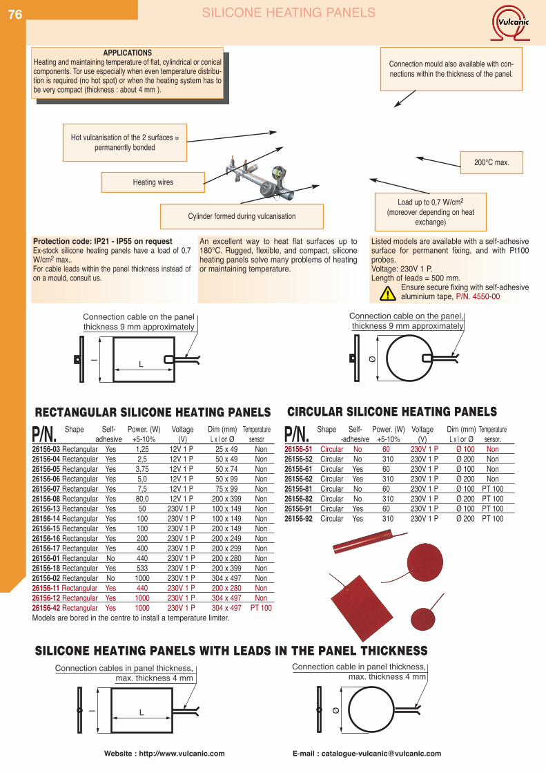
Website : http://www.vulcanic.com E-mail : [email protected]
76 SILICONE HEATING PANELS
APPLICATIONSHeating and maintaining temperature of flat, cylindrical or conicalcomponents. Tor use especially when even temperature distribu-tion is required (no hot spot) or when the heating system has tobe very compact (thickness : about 4 mm ).
Connection mould also available with con-nections within the thickness of the panel.
Cylinder formed during vulcanisation
Hot vulcanisation of the 2 surfaces =permanently bonded
Heating wires
Load up to 0,7 W/cm2(moreover depending on heat
exchange)
200°C max.
l L
Connection cables in panel thickness,max. thickness 4 mm
Connection cable on the panel thickness 9 mm approximately
l L
Ø
Connection cable in panel thickness,max. thickness 4 mm
Ø
Connection cable on the panel, thickness 9 mm approximately
P/N. Shape Self- Power. (W) Voltage Dim (mm) Temperatureadhesive +5-10% (V) L x l or Ø sensor
26156-03 Rectangular Yes 1,25 12V 1 P 25 x 49 Non26156-04 Rectangular Yes 2,5 12V 1 P 50 x 49 Non26156-05 Rectangular Yes 3,75 12V 1 P 50 x 74 Non26156-06 Rectangular Yes 5,0 12V 1 P 50 x 99 Non26156-07 Rectangular Yes 7,5 12V 1 P 75 x 99 Non26156-08 Rectangular Yes 80,0 12V 1 P 200 x 399 Non26156-13 Rectangular Yes 50 230V 1 P 100 x 149 Non26156-14 Rectangular Yes 100 230V 1 P 100 x 149 Non26156-15 Rectangular Yes 100 230V 1 P 200 x 149 Non26156-16 Rectangular Yes 200 230V 1 P 200 x 249 Non26156-17 Rectangular Yes 400 230V 1 P 200 x 299 Non26156-01 Rectangular No 440 230V 1 P 200 x 280 Non26156-18 Rectangular Yes 533 230V 1 P 200 x 399 Non26156-02 Rectangular No 1000 230V 1 P 304 x 497 Non26156-11 Rectangular Yes 440 230V 1 P 200 x 280 Non26156-12 Rectangular Yes 1000 230V 1 P 304 x 497 Non26156-42 Rectangular Yes 1000 230V 1 P 304 x 497 PT 100Models are bored in the centre to install a temperature limiter.
P/N. Shape Self- Power. (W) Voltage Dim (mm) Temperature-adhesive +5-10% (V) L x l or Ø sensor.
26156-51 Circular No 60 230V 1 P Ø 100 Non26156-52 Circular No 310 230V 1 P Ø 200 Non26156-61 Circular Yes 60 230V 1 P Ø 100 Non26156-62 Circular Yes 310 230V 1 P Ø 200 Non26156-81 Circular No 60 230V 1 P Ø 100 PT 10026156-82 Circular No 310 230V 1 P Ø 200 PT 10026156-91 Circular Yes 60 230V 1 P Ø 100 PT 10026156-92 Circular Yes 310 230V 1 P Ø 200 PT 100
An excellent way to heat flat surfaces up to180°C. Rugged, flexible, and compact, siliconeheating panels solve many problems of heatingor maintaining temperature.
Protection code: IP21 - IP55 on requestEx-stock silicone heating panels have a load of 0,7W/cm2 max..For cable leads within the panel thickness instead ofon a mould, consult us.
Listed models are available with a self-adhesivesurface for permanent fixing, and with Pt100probes.Voltage: 230V 1 P.Length of leads = 500 mm.
Ensure secure fixing with self-adhesivealuminium tape, P/N. 4550-00!
RECTANGULAR SILICONE HEATING PANELS
SILICONE HEATING PANELS WITH LEADS IN THE PANEL THICKNESS
CIRCULAR SILICONE HEATING PANELS
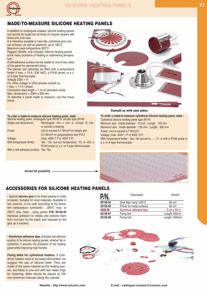
Website : http://www.vulcanic.com E-mail : [email protected]
77SILICONE HEATING PANELS
P/N. Description Amount
26156-94 Glue Max. temp. 250°C 90 cm3
26156-95 Primer for metal surfaces 90 cm3
4550-00 Aluminium adhesive tape 5 cm x 50 m26156-97 Fixing belt Length 500mm26156-98 Fixing belt Length 1000mm
To order a made-to-measure silicone heating panel, state:Silicone heating panel, rectangular type 26156 or circular type 26166Shape and dimensions: Rectangular mm x mm or circular Ø mm,
or provide a drawingPower: (not to exceed 0,7 W/cm2 on metals and
0,3 W/cm2 on polypropylene and PVC)Voltage: (max. 400V 1 P or 400V 3 P)With temperature limiter: Yes / No (cut-out temperature, °C) or with a
Pt100 probe or a J- or K-type thermocoupleWith a self-adhesive surface: Yes / No
To order a made-to-measure cylindrical silicone heating panel, state :Cylindrical silicone heating panel type 26176Minimum size : Inside diameter : 12 mm ; Length : 150 mmMaximum size : Inside diameter : 150 mm ; Length : 900 mmPower: (not to exceed 0,7 W/cm2)Voltage: (max. 400V 1 P or 400V 3 P)With temperature limiter : Yes / No pre-set to ..... °C or with a Pt100 probe ora J- or K-type thermocouple
• Special silicone glue to fix these panels to metalor plastic. Suitable for most materials. Available intwo versions, to be used according to the preva-lent temperature constraints : 200°C max. or250°C max. Note : using primer P/N. 26156-95improves adhesion to metals and protects themfrom corrosion by the acetic acid released by theglue as it hardens.
Fixing belts for cylindrical heaters. If cylin-drical heaters need to be easily dismantled, wesuggest the use of silicone belts. They aremade of the same material as the heating pan-els, and fitted at one end with two metal ringsfor fastening. Belts should be placed at 100mm maximum intervals along the cylinder.
In addition to rectangular shapes, silicone heating panelscan quickly be made into all kinds of irregular shapes withholes and cuts-outs.It is therefore possible to heat flat, cylindrical and coni-cal surfaces, as well as pipework, up to 180°C.Maximum peak temperature 200°C.Rugged, flexible, and compact, silicone heating panelssolve many problems of heating or maintaining tempera-ture.A self-adhesive surface can be added to one or two sidesof the panel for permanent fixing.The panels can optionally be fitted with a temperaturelimiter (I max. = 10 A / 230 VAC), a Pt100 probe, or a J-or K-type thermocouple.Voltage 230V 1 P.For other voltage or other phases consult us.I max. = 17 A / phase.Connection lead length = 1 m on standard model.Max. dimensions = 2000 x 900 mmTo describe a panel made to measure, use the boxesbelow.
• Aluminium adhesive tape. A simple and effectivesolution to fix silicone heating panels, whether flat orcylindrical. It ensures the protection of the heatingpanel whilst improving heat transfer.
ACCESSORIES FOR SILICONE HEATING PANELS
MADE-TO-MEASURE SILICONE HEATING PANELS
Consult us with your plans
etched foil possibility
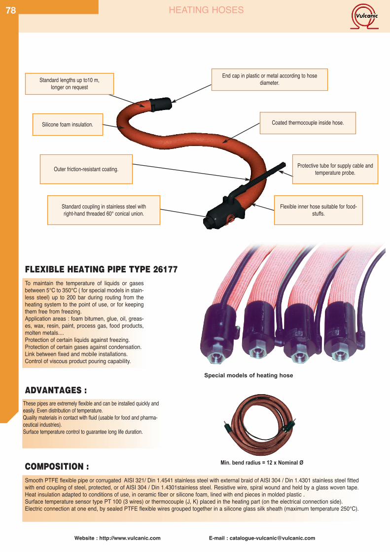
Smooth PTFE flexible pipe or corrugated AISI 321/ Din 1.4541 stainless steel with external braid of AISI 304 / Din 1.4301 stainless steel fittedwith end coupling of steel, protected, or of AISI 304 / Din 1.4301stainless steel. Resistive wire, spiral wound and held by a glass woven tape.Heat insulation adapted to conditions of use, in ceramic fiber or silicone foam, lined with end pieces in molded plastic .Surface temperature sensor type PT 100 (3 wires) or thermocouple (J, K) placed in the heating part (on the electrical connection side).Electric connection at one end, by sealed PTFE flexible wires grouped together in a silicone glass silk sheath (maximum temperature 250°C).
Website : http://www.vulcanic.com E-mail : [email protected]
78 HEATING HOSES
To maintain the temperature of liquids or gasesbetween 5°C to 350°C ( for special models in stain-less steel) up to 200 bar during routing from theheating system to the point of use, or for keepingthem free from freezing.Application areas : foam bitumen, glue, oil, greas-es, wax, resin, paint, process gas, food products,molten metals....Protection of certain liquids against freezing.Protection of certain gases against condensation.Link between fixed and mobile installations.Control of viscous product pouring capability.
These pipes are extremely flexible and can be installed quickly andeasily. Even distribution of temperature.Quality materials in contact with fluid (usable for food and pharma-ceutical industries).Surface temperature control to guarantee long life duration.
FLEXIBLE HEATING PIPE TYPE 26177
Min. bend radius = 12 x Nominal Ø
Standard lengths up to10 m,longer on request
Standard coupling in stainless steel withright-hand threaded 60° conical union.
Outer friction-resistant coating.
Flexible inner hose suitable for food-stuffs.
Silicone foam insulation. Coated thermocouple inside hose.
Protective tube for supply cable andtemperature probe.
ADVANTAGES :
COMPOSITION :
Special models of heating hose
End cap in plastic or metal according to hosediameter.
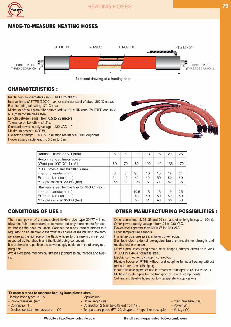
Website : http://www.vulcanic.com E-mail : [email protected]
79HEATING HOSES
Inside nominal diameters ( mm) : ND 6 to ND 25.Interior lining of PTFE (200°C max. or stainless steel of about 350°C max.).Exterior lining tolerating 170°C max.Minimum of the neutral fiber curve radius : 20 x ND (mm) for PTFE and 16 xND (mm) for stainless steel.Length between ends : from 0,5 to 25 meters.Tolerance on Length = +/- 2%.Standard power supply voltage : 230 VAC 1 PMaximum power : 3600 W.Dielectric strength : 1800 V. Insulation resistance : 100 Megohms.Power supply cable length : 0,5 m to 5 m.
To order a made-to-measure heating hose please state:Heating hose type: 26177 - Application :- Inside diameter (mm): - Hose length (m) : - max. pressure (bar) :- Connection 1 : - Connection 2 (can be different from 1) : - Power(W) :- Desired constant temperature (°C) : - Temperature probe (PT100, J-type or K-type thermocouple) - Voltage (V) :
Ø INSIDEØ OUTSIDE
L
Ø NOMINAL
RIGHT-HANDTHREADED UNION 2
RIGHT-HANDTHREADED UNION 1
Ls LENGTH
MADE-TO-MEASURE HEATING HOSES
Sectional drawing of a heating hose
Nominal Diameter ND (mm) 6 8 10 13 16 20 25Recommended linear power(W/m) per 100°C(*) for ∆-t 60 70 80 100 110 135 170PTFE flexible line for 200°C maxi :Interior diameter (mm) 6 7 9,1 10 15 18 24Exterior diameter (mm) 34 42 42 42 50 50 50Max pressure at 200°C (bar) 156 130 123 97 71 52 36Stainless steel flexible line for 350°C maxi :Interior diameter (mm) 10,5 13 16 19 25Exterior diameter (mm) 43 50 50 50 50Max pressure at 350°C (bar) 53 51 49 36 30
CHARACTERISTICS :
The linear power of a standardised flexible pipe type 26177 will notallow the fluid temperature to be raised but only compensate for loss-es through the heat insulation. Connect the measurement probes to aregulator or an electronic thermostat capable of maintaining the tem-perature at the surface of the flexible hose to the maximum set pointaccepted by the sheath and the liquid being conveyed.It is preferable to position the power supply cable on the stationary cou-pling side.Avoid excessive mechanical stresses (compression, traction and twist-ing).
CONDITIONS OF USE :Other diameters : 5, 32, 38 and 50 mm and other lengths (up to 100 m).Other power supply voltages from 24 to 230 VAC.Power levels greater than 3600 W for 230 VAC.Other temperature sensors.Higher service pressures, smaller curve radius.Stainless steel external corrugated braid or sheath for strength andmechanical protection.Other hydraulic coupling : male, bent, flanges, clamps, all will be in AISI316L/ Din 1.4404 stainless steel.Electric connection by plug-in connector.Flexible hoses of PTFE without end coupling for over-heating withoutpressure over smooth piping.Heated flexible pipes for use in explosive atmosphere (ATEX zone 1).Multiple flexible pipes for the transport of several components.Self-limiting flexible hoses for low temperature applications.
OTHER MANUFACTURING POSSIBILITIES :
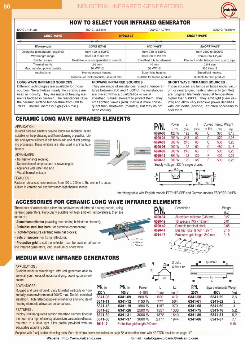
Website : http://www.vulcanic.com E-mail : [email protected]
80 INDUSTRIAL INFRARED GENERATORS
Interchangeable with English models FTE/HTE/SFE and German models FSR/FSR-2/HFS.
FEATURES :Radiation distances recommended from 100 to 200 mm. The element is encap-sulated in ceramic coil and withstands high thermal shocks.
CERAMIC LONG WAVE INFRARED ELEMENTS
ACCESSORIES FOR CERAMIC LONG WAVE INFRARED ELEMENTS
P/N. Power L l Curved Temp. Weight± 10% (mm) (mm) or flat (°C) (kg)
6020-00 125 W 122 60 C 370 0,136020-01 250 W 245 60 C 370 0,266020-03 500 W 245 60 C 500 0,266020-06 200 W 122 60 C 460 0,166020-09 500 W 245 60 F 500 0,256020-12 300 W 122 122 F 400 0,256020-13 500 W 122 122 F 500 0,25Supply voltage : 230 V single phase.
P/N. Description Weight(kg)
6020-34 Aluminium reflector (248 mm) 0,276020-42 10 spacers (M5 x 12 mm) 0,016020-40 Ceramic terminal block 0,056020-41 Bus bar (8x2) length 1,25 m 0,166014-17 Protective grid length 240 mm 0,15
APPLICATION :Straight medium wavelength infra-red generator able tosolve all your needs of industrial drying, cooking, polymeri-sation...ADVANTAGES :Rugged and careful build. Easy to install vertically or hori-zontally is an environment at 200°C max. Double electricalinsulation. High reflecting power of reflector and long life ofheating elements allows an universal use.FEATURES :Incoloy 800 triangulated section sheathed element fitted atthe heart of a high efficiency aluminium parabolic reflector,mounted in a rigid light alloy profile provided with anadjustable attaching bolts.Supplied with 2 adjustable attaching bolts. See: electronic power controllers on page 82, connection wires with KAPTON insulator on page 117.
Lc96
48
L
Ajustable2 GoujonsØ M8 x 30
MEDIUM WAVE INFRARED GENERATORS
P/N. in P/N. in Power L Lc P/N. Spare elements Weight230 V 400 V +5-10% (mm) (mm) 230V 400V (kg)6341-08 6341-09 800 W 622 412 6341-58 6341-59 2,66341-11 6341-12 1100 W 777 564 6341-61 6341-62 36341-18 6341-19 1800 W 1187 970 6341-68 6341-69 46341-25 6341-26 2500 W 1557 1330 6341-75 6341-76 5,26341-30 6341-31 3000 W 1872 1640 6341-80 6341-81 6,26341-36 6341-37 3600 W 2177 1944 6341-86 6341-87 7,16014-17 Protective grid length 240 mm 0,15
2 bolts
Wavelength LONG WAVE MID WAVE SHORT WAVEOperating temperature range(°C) from 400 to 500°C from 750 to 850°C from 2100 to 3000°C
Wavelength range from 4,3 to 3,8 µm from 2,6 to 2,8 µm from 0,9 to 1,2 µmEmitter source Resistive wire encapsulated in ceramic Sheathed tubular element Filament under halogen into quartz pipeThermal inertia 2-5 min 1-2 min 0,5-1 sec
Max. installed power density 20 kW/m2 50 kW/m2 300 kW/m2Applications Homogeneous heating.
Suitable for thick products (several mm).Superficial heating.
Suitable for humid product.Superficial heating.
Suitable for thin product.
400°C / 4,31µm
SHORT WAVE INFRARED SOURCES :Those sources are lamps or tubes under vacu-um or neutral gas; heating elements (emitter)are tungsten filaments raised at temperaturehigher than 2 000°C. They emit light (clear yel-low) and allow very intensive power densitieswith low inertia (second). Itʼs often necessary tocool them.
MIDWAVE INFRARED SOURCES :They are made of resistances raised at tempera-tures between 700 and 1 000°C; the resistancesare placed within a quartz/silica or metalsheathed tubular element to protect them. Theyemit lighting waves (red). Inertia is more conse-quent than shortwave (minutes), but they do notneed cooling.
LONG WAVE INFRARED SOURCES :Different technologies are available for thosesources. Nevertheless mainly the ceramics areused in industry. They are made of heating ele-ments bedded in ceramic. The resistances raisethe ceramic surface temperature from 300 to700°C. Thermal inertia is high (>3-5 min.)
LONG WAVE MIDWAVE SHORT WAVE
APPLICATION :Infrared ceramic emitters provide longwave radiation ideallysuitable for the preheating and thermoforming of plastics, rub-ber and synthetic fibers in addition to skin and blister packag-ing processes. These emitters are also used in animal hus-bandry.ADVANTAGES :- No maintenance required- No deviation of temperatures or wave lengths- Appliance with water and acid- Visual thermal indicator
These sets of accessories allow the achievement of infrared heating panels, usingceramic generators. Particularly suitable for high ambient temperatures, they aremade of :- Aluminium reflector (avoiding overheating behind the element);- Stainless steel bus bars (for electrical connection);- High-temperature ceramic terminal blocks;- Sets of spacers (for fixing reflectors);- Protective grid to suit the reflector ; can be used on all our in-line infrared generators, long, medium or short wave.
650°C / 3,14µm 1200°C / 1,97µm 3000°C / 0,89µm
H = 20 mmL = 40 mml = 30 mm
HOW TO SELECT YOUR INFRARED GENERATOR
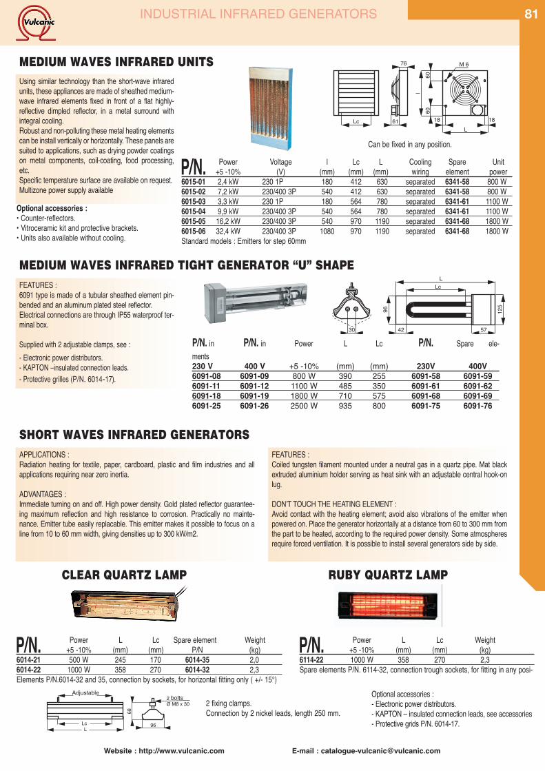
Website : http://www.vulcanic.com E-mail : [email protected]
81
Optional accessories :• Counter-reflectors.• Vitroceramic kit and protective brackets.• Units also available without cooling.
60
1861
76
Lc 18L
M 6
60l
P/N. Power Voltage l Lc L Cooling Spare Unit+5 -10% (V) (mm) (mm) (mm) wiring element power
6015-01 2,4 kW 230 1P 180 412 630 separated 6341-58 800 W6015-02 7,2 kW 230/400 3P 540 412 630 separated 6341-58 800 W6015-03 3,3 kW 230 1P 180 564 780 separated 6341-61 1100 W6015-04 9,9 kW 230/400 3P 540 564 780 separated 6341-61 1100 W6015-05 16,2 kW 230/400 3P 540 970 1190 separated 6341-68 1800 W6015-06 32,4 kW 230/400 3P 1080 970 1190 separated 6341-68 1800 WStandard models : Emitters for step 60mm
Using similar technology than the short-wave infraredunits, these appliances are made of sheathed medium-wave infrared elements fixed in front of a flat highly-reflective dimpled reflector, in a metal surround withintegral cooling.Robust and non-polluting these metal heating elementscan be install vertically or horizontally. These panels aresuited to applications, such as drying powder coatingson metal components, coil-coating, food processing,etc.Specific temperature surface are available on request.Multizone power supply available
MEDIUM WAVES INFRARED UNITS
LLc
42 5730
96 125
MEDIUM WAVES INFRARED TIGHT GENERATOR “U” SHAPE
P/N. in P/N. in Power L Lc P/N. Spare ele-ments230 V 400 V +5 -10% (mm) (mm) 230V 400V6091-08 6091-09 800 W 390 255 6091-58 6091-596091-11 6091-12 1100 W 485 350 6091-61 6091-626091-18 6091-19 1800 W 710 575 6091-68 6091-696091-25 6091-26 2500 W 935 800 6091-75 6091-76
INDUSTRIAL INFRARED GENERATORS
Can be fixed in any position.
FEATURES :6091 type is made of a tubular sheathed element pin-bended and an aluminum plated steel reflector.Electrical connections are through IP55 waterproof ter-minal box.
Supplied with 2 adjustable clamps, see :- Electronic power distributors.- KAPTON –insulated connection leads.- Protective grilles (P/N. 6014-17).
SHORT WAVES INFRARED GENERATORSAPPLICATIONS :Radiation heating for textile, paper, cardboard, plastic and film industries and allapplications requiring near zero inertia.
ADVANTAGES :Immediate turning on and off. High power density. Gold plated reflector guarantee-ing maximum reflection and high resistance to corrosion. Practically no mainte-nance. Emitter tube easily replacable. This emitter makes it possible to focus on aline from 10 to 60 mm width, giving densities up to 300 kW/m2.
FEATURES :Coiled tungsten filament mounted under a neutral gas in a quartz pipe. Mat blackextruded aluminium holder serving as heat sink with an adjustable central hook-onlug.
DONʼT TOUCH THE HEATING ELEMENT :Avoid contact with the heating element; avoid also vibrations of the emitter whenpowered on. Place the generator horizontally at a distance from 60 to 300 mm fromthe part to be heated, according to the required power density. Some atmospheresrequire forced ventilation. It is possible to install several generators side by side.
Adjustablebolts 2 fixing clamps.
Connection by 2 nickel leads, length 250 mm.
Optional accessories :- Electronic power distributors.- KAPTON – insulated connection leads, see accessories- Protective grids P/N. 6014-17.
P/N. Power L Lc Weight+5 -10% (mm) (mm) (kg)
6114-22 1000 W 358 270 2,3Spare elements P/N. 6114-32, connection trough sockets, for fitting in any posi-
P/N. Power L Lc Spare element Weight+5 -10% (mm) (mm) P/N (kg)
6014-21 500 W 245 170 6014-35 2,06014-22 1000 W 358 270 6014-32 2,3Elements P/N.6014-32 and 35, connection by sockets, for horizontal fitting only ( +/- 15°)
CLEAR QUARTZ LAMP RUBY QUARTZ LAMP
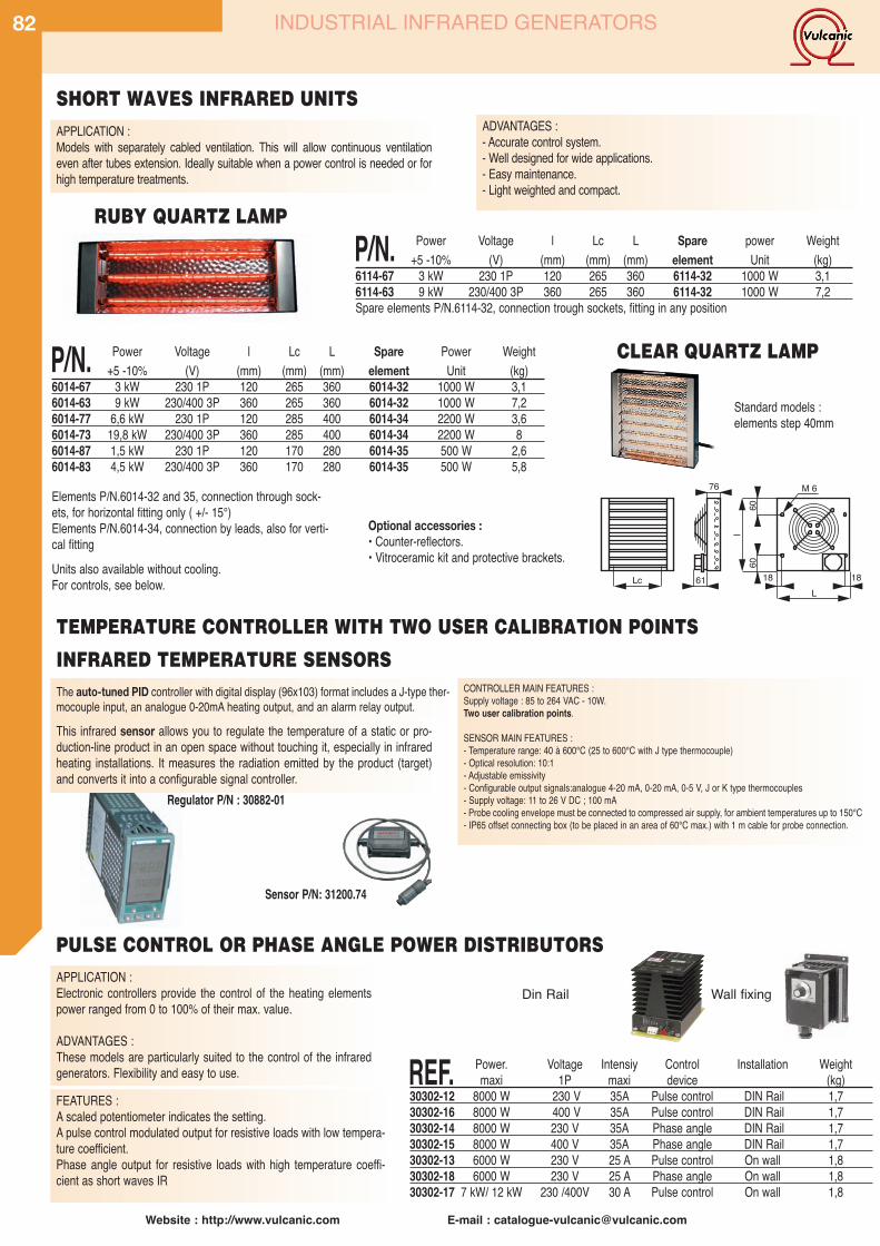
CONTROLLER MAIN FEATURES :Supply voltage : 85 to 264 VAC - 10W.Two user calibration points.
SENSOR MAIN FEATURES :- Temperature range: 40 à 600°C (25 to 600°C with J type thermocouple)- Optical resolution: 10:1- Adjustable emissivity- Configurable output signals:analogue 4-20 mA, 0-20 mA, 0-5 V, J or K type thermocouples- Supply voltage: 11 to 26 V DC ; 100 mA- Probe cooling envelope must be connected to compressed air supply, for ambient temperatures up to 150°C- IP65 offset connecting box (to be placed in an area of 60°C max.) with 1 m cable for probe connection.
82
Website : http://www.vulcanic.com E-mail : [email protected]
Units also available without cooling.For controls, see below.
Optional accessories :• Counter-reflectors.• Vitroceramic kit and protective brackets.
P/N. Power Voltage l Lc L Spare power Weight+5 -10% (V) (mm) (mm) (mm) element Unit (kg)
6114-67 3 kW 230 1P 120 265 360 6114-32 1000 W 3,16114-63 9 kW 230/400 3P 360 265 360 6114-32 1000 W 7,2Spare elements P/N.6114-32, connection trough sockets, fitting in any position
P/N. Power Voltage l Lc L Spare Power Weight+5 -10% (V) (mm) (mm) (mm) element Unit (kg)
6014-67 3 kW 230 1P 120 265 360 6014-32 1000 W 3,16014-63 9 kW 230/400 3P 360 265 360 6014-32 1000 W 7,26014-77 6,6 kW 230 1P 120 285 400 6014-34 2200 W 3,66014-73 19,8 kW 230/400 3P 360 285 400 6014-34 2200 W 86014-87 1,5 kW 230 1P 120 170 280 6014-35 500 W 2,66014-83 4,5 kW 230/400 3P 360 170 280 6014-35 500 W 5,8
Standard models :elements step 40mm
Elements P/N.6014-32 and 35, connection through sock-ets, for horizontal fitting only ( +/- 15°)Elements P/N.6014-34, connection by leads, also for verti-cal fitting
PULSE CONTROL OR PHASE ANGLE POWER DISTRIBUTORS
TEMPERATURE CONTROLLER WITH TWO USER CALIBRATION POINTS
INFRARED TEMPERATURE SENSORS
Sensor P/N: 31200.74
Regulator P/N : 30882-01
SHORT WAVES INFRARED UNITS
INDUSTRIAL INFRARED GENERATORS
APPLICATION :Models with separately cabled ventilation. This will allow continuous ventilationeven after tubes extension. Ideally suitable when a power control is needed or forhigh temperature treatments.
ADVANTAGES :- Accurate control system.- Well designed for wide applications.- Easy maintenance.- Light weighted and compact.
CLEAR QUARTZ LAMP
RUBY QUARTZ LAMP
The auto-tuned PID controller with digital display (96x103) format includes a J-type ther-mocouple input, an analogue 0-20mA heating output, and an alarm relay output.This infrared sensor allows you to regulate the temperature of a static or pro-duction-line product in an open space without touching it, especially in infraredheating installations. It measures the radiation emitted by the product (target)and converts it into a configurable signal controller.
APPLICATION :Electronic controllers provide the control of the heating elementspower ranged from 0 to 100% of their max. value.
ADVANTAGES :These models are particularly suited to the control of the infraredgenerators. Flexibility and easy to use.
FEATURES :A scaled potentiometer indicates the setting.A pulse control modulated output for resistive loads with low tempera-ture coefficient.Phase angle output for resistive loads with high temperature coeffi-cient as short waves IR
REF. Power. Voltage Intensiy Control Installation Weightmaxi 1P maxi device (kg)
30302-12 8000 W 230 V 35A Pulse control DIN Rail 1,730302-16 8000 W 400 V 35A Pulse control DIN Rail 1,730302-14 8000 W 230 V 35A Phase angle DIN Rail 1,730302-15 8000 W 400 V 35A Phase angle DIN Rail 1,730302-13 6000 W 230 V 25 A Pulse control On wall 1,830302-18 6000 W 230 V 25 A Phase angle On wall 1,830302-17 7 kW/ 12 kW 230 /400V 30 A Pulse control On wall 1,8
Din Rail Wall fixing
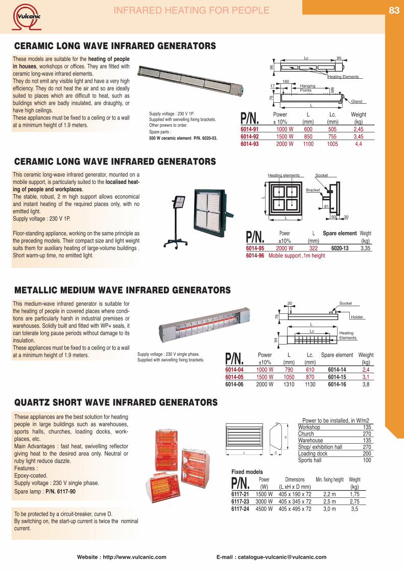
Website : http://www.vulcanic.com E-mail : [email protected]
83INFRARED HEATING FOR PEOPLE
These appliances are the best solution for heatingpeople in large buildings such as warehouses,sports halls, churches, loading docks, work-places, etc.Main Advantages : fast heat, swivelling reflectorgiving heat to the desired area only. Neutral orruby light reduce dazzle.Features :Epoxy-coated.Supply voltage : 230 V single phase.Spare lamp : P/N. 6117-90
H
L D
Fixed models
P/N. Power Dimensions Min. fixing height Weight(W) (L xH x D mm) (kg)
6117-21 1500 W 405 x 190 x 72 2,2 m 1,756117-23 3000 W 405 x 345 x 72 2,5 m 2,756117-24 4500 W 405 x 495 x 72 3,0 m 3,5
QUARTZ SHORT WAVE INFRARED GENERATORS
Power to be installed, in W/m2Workshop 135Church 270Warehouse 135Shop/ exhibition hall 270Loading dock 200Sports hall 100
20 Socket
Holder76
This medium-wave infrared generator is suitable forthe heating of people in covered places where condi-tions are particularly harsh in industrial premises orwarehouses. Solidly built and fitted with WP+ seals, itcan tolerate long pause periods without damage to itsinsulation.These appliances must be fixed to a ceiling or to a wallat a minimum height of 1.9 meters. Supply voltage : 230 V single phase.
Supplied with swivelling fixing brackets.
LLc Heating
Elements
94
METALLIC MEDIUM WAVE INFRARED GENERATORS
P/N. Power L Lc. Spare element Weight±10% (mm) (mm) (kg)
6014-04 1000 W 790 610 6014-14 2,46014-05 1500 W 1050 870 6014-15 3,16014-06 2000 W 1310 1130 6014-16 3,8
These models are suitable for the heating of peoplein houses, workshops or offices. They are fitted withceramic long-wave infrared elements.They do not emit any visible light and have a very highefficiency. They do not heat the air and so are ideallysuited to places which are difficult to heat, such asbuildings which are badly insulated, are draughty, orhave high ceilings.These appliances must be fixed to a ceiling or to a wallat a minimum height of 1.9 meters.
Supply voltage : 230 V 1P.Supplied with swivelling fixing brackets.Other powers to order.Spare parts :500 W ceramic element P/N. 6020-03.
Lc 95
Heating Elements
96
160
L
M617 Hanging
Gland
Points
76
CERAMIC LONG WAVE INFRARED GENERATORS
P/N. Power L Lc. Weight± 10% (mm) (mm) (kg)
6014-91 1000 W 600 505 2,456014-92 1500 W 850 755 3,456014-93 2000 W 1100 1005 4,4
This ceramic long-wave infrared generator, mounted on amobile support, is particularly suited to the localised heat-ing of people and workplaces.The stable, robust, 2 m high support allows economicaland instant heating of the required places only, with noemitted light.Supply voltage : 230 V 1P.
Floor-standing appliance, working on the same principle asthe preceding models. Their compact size and light weightsuits them for auxiliary heating of large-volume buildings .Short warm-up time, no emitted light.
Heating elements
L 50
81
30
L
Socket
Bracket
P/N. Power L Spare element Weight±10% (mm) (kg)
6014-95 2000 W 322 6020-13 3,356014-96 Mobile support ,1m height
CERAMIC LONG WAVE INFRARED GENERATORS
To be protected by a circuit-breaker, curve D.By switching on, the start-up current is twice the nominalcurrent.
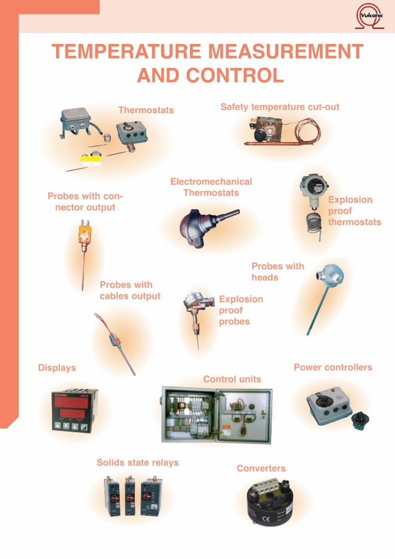
Probes with con-nector output
Explosionproof probes
Explosionproof thermostats
Displays Power controllers
Probes withheads
Solids state relays
Probes withcables output
Thermostats
ElectromechanicalThermostats
Safety temperature cut-out
Control units
TEMPERATURE MEASUREMENTAND CONTROL
Converters
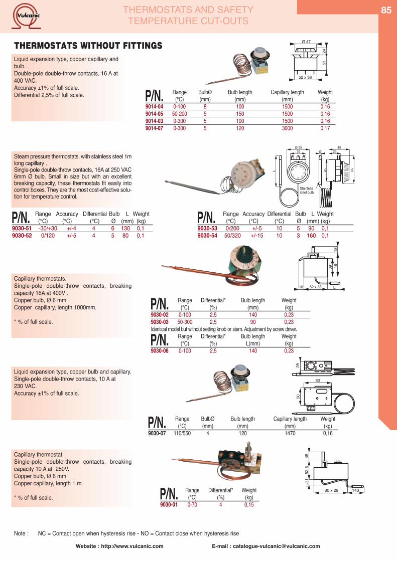
Website : http://www.vulcanic.com E-mail : [email protected]
85
Steam pressure thermostats, with stainless steel 1mlong capillary .Single-pole double-throw contacts, 16A at 250 VAC 6mm Ø bulb. Small in size but with an excellentbreaking capacity, these thermostats fit easily intocontrol boxes. They are the most cost-effective solu-tion for temperature control.
P/N. Range Accuracy Differential Bulb L Weight(°C) (°C) (°C) Ø (mm) (kg)
9030-51 -30/+30 +/-4 4 6 130 0,19030-52 0/120 +/-5 4 5 80 0,1
45L 65
25Ø3545Ø 55
Capillaire eninox Lgr 1m
Bulbe inox
+30°
+20° +10° 0°- 10°
-20°-30°°C
P/N. Range Accuracy Differential Bulb L Weight(°C) (°C) (°C) Ø (mm) (kg)
9030-53 0/200 +/-5 10 5 90 0,19030-54 50/320 +/-15 10 3 160 0,1
Stainlesssteel bulb
THERMOSTATS AND SAFETYTEMPERATURE CUT-OUTS
52 x 38
Ø 47
5124
P/N. Range BulbØ Bulb length Capillary length Weight(°C) (mm) (mm) (mm) (kg)
9014-04 0-100 8 100 1500 0,169014-05 50-200 5 150 1500 0,169014-03 0-300 5 100 1500 0,169014-07 0-300 5 120 3000 0,17
Liquid expansion type, copper capillary andbulb. Double-pole double-throw contacts, 16 A at400 VAC. Accuracy ±1% of full scale. Differential 2,5% of full scale.
THERMOSTATS WITHOUT FITTINGS
Capillary thermostats. Single-pole double-throw contacts, breakingcapacity 16A at 400V .Copper bulb, Ø 6 mm.Copper capillary, length 1000mm.
* % of full scale.
P/N. Range Differential* Bulb length Weight(°C) (%) (mm) (kg)
9030-02 0-100 2,5 140 0,239030-03 50-300 2,5 90 0,23Identical model but without setting knob or stem. Adjustment by screw driver.
P/N. Range Differential* Bulb length Weight(°C) (%) L(mm) (kg)
9030-08 0-100 2,5 140 0,23
52 x 38 L10
39 4818
80
5028
Liquid expansion type, copper bulb and capillary.Single-pole double-throw contacts, 10 A at 230 VAC. Accuracy ±1% of full scale.
P/N. Range BulbØ Bulb length Capillary length Weight(°C) (mm) (mm) (mm) (kg)
9030-07 110/550 4 120 1470 0,16
80 x 29 140
4552
,511
P/N. Range Differential* Weight(°C) (%) (kg)
9030-01 0-70 4 0,15
Capillary thermostat. Single-pole double-throw contacts, breakingcapacity 10 A at 250V. Copper bulb, Ø 6 mm. Copper capillary, length 1 m.
* % of full scale.
Note : NC = Contact open when hysteresis rise - NO = Contact close when hysteresis rise

86
Website : http://www.vulcanic.com E-mail : [email protected]
THERMOSTATS AND SAFETYTEMPERATURE CUT-OUTS
Liquid expansion type thermostat including a safe-ty temperature cut-out function with manual reset.Temperature range +15°C to +85°C.Safety temperature pre-set to 110°C.Triple-pole normally close contacts, breakingcapacity 3x20A at 400V.
3040
15
15 2 CAPILLAIRES
15
45 5565
P/N. Range BulbØ Bulb length Capillary length(°C) (mm) (mm) (mm)
Thermostat +15/+85 6 95 900Safety temp Fixed at 110°C 6 120 900
THREE PHASE SAFETY TEMPERATURE CUT-OUT THERMOSTAT
9014-13
Designed to protect water-heating installationsagainst overheating, these temperature cut-outsare adjustable between 90° to 110°C and aremanually reset. They are fitted with a 1m long capillary and a6,5x90 mm bulb. Circuit is open if the sensor is broken. Single-pole normally close contacts, breakingcapacity 15A at 230V. P/N. Cut-out Cut-out Max.
temp. tolerance bulb temp.9030-31 90/110°C +0°C/-6°C 120°C
POSITIVE SAFETY TEMPERATURE CUT-OUTS WITH ADJUSTABLE THRESHOLD
Simple to install and use, these box-mounted liquid-expansion thermostats are fixed to the tank (or pipe)and heated via the supplied copper thermowell. IP40 box. Copper probe, length 95mm. Single-pole double-throw contacts, breaking capacity15A at 250VAC, 10A at 400VAC.Differential 6°K, Accuracy ±3°C, Max. working pressure: 10 bar.
P/N. Range (°C) Max. bulb (°C) temp.
9030-11 10/90 1209030-12 40/120 150
These positive safety temperature cut-outs, (box mounted),with manual reset, are used to protect water heating systemsagainst overheating.Circuit is open if the sensor is broken. Simple to install and use, these box-mounted liquid-expan-sion thermostats are fixed to the tank (or pipe) and heated viathe supplied copper thermowell. IP40 box.Copper probe, length 95mm. Single-pole double-throw contacts, breaking capacity 15A at250V, 10A at 400V Differential 6°K, . Max. working pressure : 10 bar. P/N. Cut-out Cut-out Max.
temp. Accuracy bulb temp.9030-21 100°C +0°C/-6°C 120°C
ENCLOSED ROD-TYPE POSITIVE SAFETY TEMPERATURE CUT-OUTS
P/N. Cut-out Cut-out Max. temp. tolerance bulb temp.
9030-41 100°C +0°C/-6°C 120°C
Box containing a adjustable thermostat between 10°C to 90°C anda temperature cut-out, pre-set to 100°C, with manual reset. Circuitis open if the sensor is broken. Simple to install and use, these box-mounted liquid-expansionthermostats are fixed to the tank (or pipe) and heated via the sup-plied copper thermowell. IP40 box. Copper probe, length 95mm. Thermostat : single-pole double-throw contacts.,breaking capacity15A at 250V , 10A at 400V. Cut-out : normally close contactDifferential 6°K, Max. working pressure : 10 bar.
4110159580
120
20
Ø 16
708
1/2” Gaz Con.
42101512040
145
12,5
Ø 8
708
1/2” Gaz Con.
42101512040
145
12,5
Ø 8
708
1/2” Gaz Con.
ENCLOSED THERMOSTATS AND POSITIVE SAFETY TEMPERATURE CUT-OUTS
ENCLOSED ROD-TYPE THERMOSTATS
1/2” BSP
1/2” BSP
1/2” BSP
2 CAPILLARIES
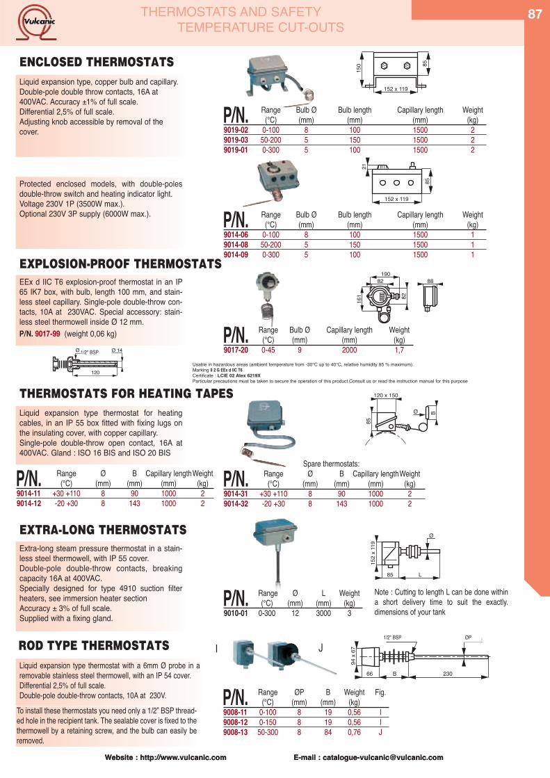
Website : http://www.vulcanic.com E-mail : [email protected] : http://www.vulcanic.com E-mail : [email protected]
To install these thermostats you need only a 1/2” BSP thread-ed hole in the recipient tank. The sealable cover is fixed to thethermowell by a retaining screw, and the bulb can easily beremoved.
66 B 230
1/2" Gaz Co. Ø DDG
94 x
67
P/N. Range ØP B Weight Fig.(°C) (mm) (mm) (kg)
9008-11 0-100 8 19 0,56 I9008-12 0-150 8 19 0,56 I9008-13 50-300 8 84 0,76 J
I JROD TYPE THERMOSTATSLiquid expansion type thermostat with a 6mm Ø probe in aremovable stainless steel thermowell, with an IP 54 cover. Differential 2,5% of full scale. Double-pole double-throw contacts, 10A at 230V.
85
150
152 x 119
85
21
152 x 119
19082 88
161 82
Liquid expansion type, copper bulb and capillary. Double-pole double throw contacts, 16A at400VAC. Accuracy ±1% of full scale. Differential 2,5% of full scale. Adjusting knob accessible by removal of thecover.
Protected enclosed models, with double-polesdouble-throw switch and heating indicator light. Voltage 230V 1P (3500W max.).Optional 230V 3P supply (6000W max.).
EEx d IIC T6 explosion-proof thermostat in an IP65 IK7 box, with bulb, length 100 mm, and stain-less steel capillary. Single-pole double-throw con-tacts, 10A at 230VAC. Special accessory: stain-less steel thermowell inside Ø 12 mm. P/N. 9017-99 (weight 0,06 kg)
B
85
Ø
120 x 150
Liquid expansion type thermostat for heatingcables, in an IP 55 box fitted with fixing lugs onthe insulating cover, with copper capillary.Single-pole double-throw open contact, 16A at400VAC. Gland : ISO 16 BIS and ISO 20 BIS
Extra-long steam pressure thermostat in a stain-less steel thermowell, with IP 55 cover.Double-pole double-throw contacts, breakingcapacity 16A at 400VAC. Specially designed for type 4910 suction filterheaters, see immersion heater section Accuracy ± 3% of full scale.Supplied with a fixing gland.
Ø
85 L
152
x 119
120
Ø 14Ø 1/2" Gaz con.
P/N. Range Ø B Capillary lengthWeight(°C) (mm) (mm) (mm) (kg)
9014-11 +30 +110 8 90 1000 29014-12 -20 +30 8 143 1000 2
P/N. Range Ø L Weight(°C) (mm) (mm) (kg)
9010-01 0-300 12 3000 3
ENCLOSED THERMOSTATS
EXPLOSION-PROOF THERMOSTATS
THERMOSTATS FOR HEATING TAPES
EXTRA-LONG THERMOSTATS
P/N. Range Bulb Ø Bulb length Capillary length Weight(°C) (mm) (mm) (mm) (kg)
9019-02 0-100 8 100 1500 29019-03 50-200 5 150 1500 29019-01 0-300 5 100 1500 2
P/N. Range Bulb Ø Bulb length Capillary length Weight(°C) (mm) (mm) (mm) (kg)
9014-06 0-100 8 100 1500 19014-08 50-200 5 150 1500 19014-09 0-300 5 100 1500 1
P/N. Range Bulb Ø Capillary length Weight(°C) (mm) (mm) (kg)
9017-20 0-45 9 2000 1,7
Spare thermostats:
P/N. Range Ø B Capillary lengthWeight(°C) (mm) (mm) (mm) (kg)
9014-31 +30 +110 8 90 1000 29014-32 -20 +30 8 143 1000 2
Note : Cutting to length L can be done withina short delivery time to suit the exactly.dimensions of your tank
1/2" BSP ØP
1/2" BSP
THERMOSTATS AND SAFETYTEMPERATURE CUT-OUTS
87
Usable in hazardous areas (ambient temperature from -30°C up to 40°C, relative humidity 95 % maximum).Marking II 2 G EEx d IIC T6 Certificate : LCIE 02 Atex 6219XParticular precautions must be taken to secure the operation of this product.Consult us or read the instruction manual for this purpose

88
Website : http://www.vulcanic.com E-mail : [email protected] : http://www.vulcanic.com E-mail : [email protected]
Temperature limiter, bimetallic expansion type withautomatic reset, for air temperature alarms. Normallyclose contact, breaking capacity 10A at 250VAC.Differential 12°C. 5
40/4
3
Ø 16 P/N. Cut-out Weight
temp. (kg)53691-01 90°C 0,019009-01 110°C 0,01
Temperature limiter, positive safety steam pressure type,with automatic or manual reset. Capillary Ø 1,9 mm, length 1 m. Normally close contact, breaking capacity 16A at250VAC. Differential 12°C. 6
40/4
3
Ø 31 P/N. Cut-out Reset Weight
temp. (kg)54229-01 90°C auto. 0,0553710-01 90°C manu. 0,05
Temperature limiter, liquid expansion type with capil-lary. Single-pole double-throw contacts, breakingcapacity 16A at 400VAC. Manual reset. Stainless steelcapillary, length1 m and stainless steel bulb, diameter 6mm.
P/N. Range Bulb Weight(°C) L (mm) (kg)
9030-05 +50 +300 85 0,159030-06 +20 +500 300 0,15
This timer allows two electrical appliances to be switched onand off independently according to a daily and weekly cycle.42 switching orders can be programmed for any time over amaximum period of a week. Minimum programming interval : 1 minute. Digital display giving hour, working state and programming. Quick summer/winter time changeover. Backup in case of power cuts : 150 hours max.
double throw open contacts : 16A at 250VACResistive load.
P/N. Voltage Weight(V) (kg)
9025-12 230V 50 Hz 0,2
Simple model designed for temperature control inrooms or air-conditioned enclosures. Normally closecontact, breaking capacity 10A at 250VAC. Differential0,6°C.
71
71
31
7 P/N. Range Weight(°C) (kg)
9014-20 5/30 0,12
Suitable for outdoor use, for frost protection of watertanks, pipes, pools... Sealable IP 55 cover. Normallyclose contact, breaking capacity 10A at 250VAC.Differential 3°C. 55 122
120 P/N. Range Weight
(°C) (kg)9014-23 -20 / +30 0,41
AMBIENT AIR THERMOSTATS
PRE-SET SAFETY TEMPERATURE LIMITERS
52 x 38 L10
39 48
SAFETY CUT-OUTS WITH ADJUSTABLE THRESHOLD
TIMERS
26
101 66 72
17 15
THERMOSTATS AND SAFETYTEMPERATURE CUT-OUTS
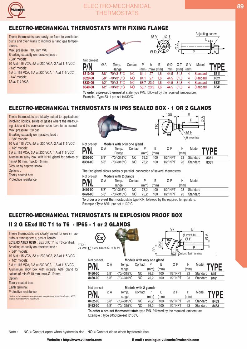
Website : http://www.vulcanic.com E-mail : [email protected]
89
Website : http://www.vulcanic.com E-mail : [email protected]
ELECTRO-MECHANICALTHERMOSTATS
These thermostats can easily be fixed to ventilationducts and oven walls to monitor air and gas temper-atures. Max. pressure : 100 mm WCBreaking capacity on resistive load :- 5/8” models:10 A at 115 VCA, 5A at 230 VCA, 2 A at 115 VCC.- 1/2” models:5 A at 115 VCA, 3 A at 230 VCA, 1 A at 115 VCC .- 1/4” models:1A at 115 VCA
��
� �
�� �
� �� ������� �
� �
Not pre-set
P/N Ø A Temp. Contact P h E Ø D Ø T Ø V ModelRange (mm) (mm) (mm) (mm) (mm) (mm)
8310-00 5/8” -70/+315°C NC 84,1 27 1,6 44,5 31,8 4 Standard8320-00 5/8” -70/+315°C NO 84,1 27 1,6 44,5 31,8 4 Standard8330-00 1/2” -70/+315°C NC 58,7 23,9 1,6 44,5 31,8 4 Standard8340-00 1/2” -70/+315°C NO 58,7 23,9 1,6 44,5 31,8 4 StandardTo order a pre-set thermostat state type P/N. followed by the required temperature.Example : Type 8311 pre-set to130°C.
ELECTRO-MECHANICAL THERMOSTATS WITH FIXING FLANGE
TYPE8311832183318341
ELECTRO-MECHANICAL THERMOSTATS IN IP65 SEALED BOX - 1 OR 2 GLANDSThese thermostats are ideally suited to applicationsinvolving liquids, solids or gases where the measur-ing side and the connection side have to be sealed. Max. pressure : 20 bar.Breaking capacity on resistive load :- 5/8” models:10 A at 115 VCA, 5A at 230 VCA, 2 A at 115 VCC.- 1/2” models:5 A at 115 VCA, 3 A at 230 VCA, 1 A at 115 VCC.Aluminium alloy box with N°16 gland for cables ofmin.Ø 10 mm, max.Ø 15 mm.Closure by captive screw.Options :Epoxy-coated box.Protective resistance.
���
��
�
����
� �
�� ���
These thermostats are ideally suited for use in haz-ardous atmospheres, gas or liquids.LCIE.03 ATEX 6339 . EEx dIIC T1 to T6 certified.Breaking capacity on resistive load :- 5/8” models:10 A at 115 VCA, 5A at 230 VCA, 2 A at 115 VCC.- 1/2” models:5 A at 115 VCA, 3 A at 230 VCA, 1 A at 115 VCC.Aluminium alloy box with integral ADF gland forcables of min.Ø 10 mm, max.Ø 19 mm.Option :Epoxy-coated box.Earth terminal.Protective resistance.Usable in hazardous areas (ambient temperature from -30°C up to 40°C,relative humidity 95 % maximum).
���
��� � �� ��
� �
���
�� �
������ � ���� �� � ���
Not pre-set Models with only one gland
P/N. Ø A Temp. Contact P E Ø F H Modelrange (mm) (mm) (mm)
8450-00 5/8” -70/+315°C NC 76,2 100 1/2” NPT 23 Standard8460-00 5/8” -70/+315°C NO 76,2 100 1/2” NPT 23 Standard
Not pre-set Models with 2 glands
P/N. Ø A Temp. Contact P E Ø F H Modelrange (mm) (mm) (mm)
8452-00 5/8” -70/+315°C NC 76,2 100 1/2” NPT 23 Standard8462-00 5/8” -70/+315°C NO 76,2 100 1/2” NPT 23 StandardTo order a pre-set thermostat state type P/N. followed by the required temperature.Example : Type 8453 pre-set to130°C.
TYPE84518461
TYPE84538463
Adjusting screw
H over flats
Not pre-set Models with only one gland
P/N. Ø A Temp. Contact P E Ø F H ModelRange (mm) (mm) (mm)
8350-00 5/8” -70/+315°C NC 76,2 100 1/2” NPT 23 Standard8360-00 5/8” -70/+315°C NO 76,2 100 1/2” NPT 23 Standard
The 2nd gland allows series or parallel connection of several thermostats.Not pre-set Models with 2 glands
P/N. Ø A Temp. Contact P E Ø F H Modelrange (mm) (mm) (mm)
8410-00 5/8” -70/+315°C NC 76,2 100 1/2” NPT 23 Standard8420-00 5/8” -70/+315°C NO 76,2 100 1/2” NPT 23 StandardTo order a pre-set thermostat state type P/N. followed by the required temperature.Example : Type 8351 pre-set to130°C.
TYPE83518361
Option : Earth terminal
H over flats
ATEX :CE 0081 II 2 G EEx d IIC T1 to T6
ELECTRO-MECHANICAL THERMOSTATS IN EXPLOSION PROOF BOX
II 2 G EExd IIC T1 to T6 - IP65 - 1 or 2 GLANDS
Note : NC = Contact open when hysteresis rise - NO = Contact close when hysteresis rise
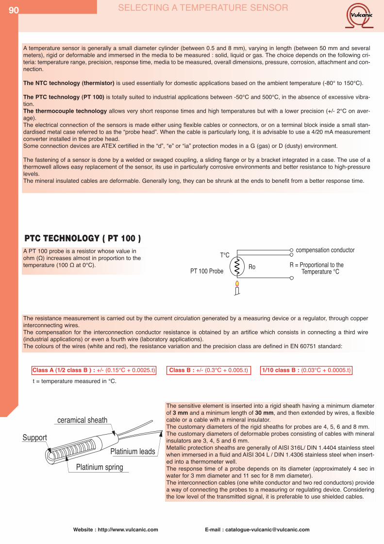
90
Website : http://www.vulcanic.com E-mail : [email protected]
A temperature sensor is generally a small diameter cylinder (between 0.5 and 8 mm), varying in length (between 50 mm and severalmeters), rigid or deformable and immersed in the media to be measured : solid, liquid or gas. The choice depends on the following cri-teria: temperature range, precision, response time, media to be measured, overall dimensions, pressure, corrosion, attachment and con-nection.
The NTC technology (thermistor) is used essentially for domestic applications based on the ambient temperature (-80° to 150°C).
The PTC technology (PT 100) is totally suited to industrial applications between -50°C and 500°C, in the absence of excessive vibra-tion. The thermocouple technology allows very short response times and high temperatures but with a lower precision (+/- 2°C on aver-age).The electrical connection of the sensors is made either using flexible cables or connectors, or on a terminal block inside a small stan-dardised metal case referred to as the “probe head”. When the cable is particularly long, it is advisable to use a 4/20 mA measurementconverter installed in the probe head.Some connection devices are ATEX certified in the “d”, “e” or “ia” protection modes in a G (gas) or D (dusty) environment.
The fastening of a sensor is done by a welded or swaged coupling, a sliding flange or by a bracket integrated in a case. The use of athermowell allows easy replacement of the sensor, its use in particularly corrosive environments and better resistance to high-pressurelevels.The mineral insulated cables are deformable. Generally long, they can be shrunk at the ends to benefit from a better response time.
PTC TECHNOLOGY ( PT 100 )A PT 100 probe is a resistor whose value inohm (Ω) increases almost in proportion to thetemperature (100 Ω at 0°C).
���
�� � � ������ �� �� ����������� ���� ��� ����
���� ����� �� �����
The resistance measurement is carried out by the current circulation generated by a measuring device or a regulator, through copperinterconnecting wires.The compensation for the interconnection conductor resistance is obtained by an artifice which consists in connecting a third wire(industrial applications) or even a fourth wire (laboratory applications).The colours of the wires (white and red), the resistance variation and the precision class are defined in EN 60751 standard:
Class A (1/2 class B ) : +/- (0.15°C + 0.0025.t)
The sensitive element is inserted into a rigid sheath having a minimum diameterof 3 mm and a minimum length of 30 mm, and then extended by wires, a flexiblecable or a cable with a mineral insulator.The customary diameters of the rigid sheaths for probes are 4, 5, 6 and 8 mm.The customary diameters of deformable probes consisting of cables with mineralinsulators are 3, 4, 5 and 6 mm.Metallic protection sheaths are generally of AISI 316L/ DIN 1.4404 stainless steelwhen immersed in a fluid and AISI 304 L / DIN 1.4306 stainless steel when insert-ed into a thermometer well.The response time of a probe depends on its diameter (approximately 4 sec inwater for 3 mm diameter and 11 sec for 8 mm diameter).The interconnection cables (one white conductor and two red conductors) providea way of connecting the probes to a measuring or regulating device. Consideringthe low level of the transmitted signal, it is preferable to use shielded cables.
t = temperature measured in °C.Class B : +/- (0.3°C + 0.005.t) 1/10 class B : (0.03°C + 0.0005.t)
�������
������ �����
������ ����
������ �����
SELECTING A TEMPERATURE SENSOR
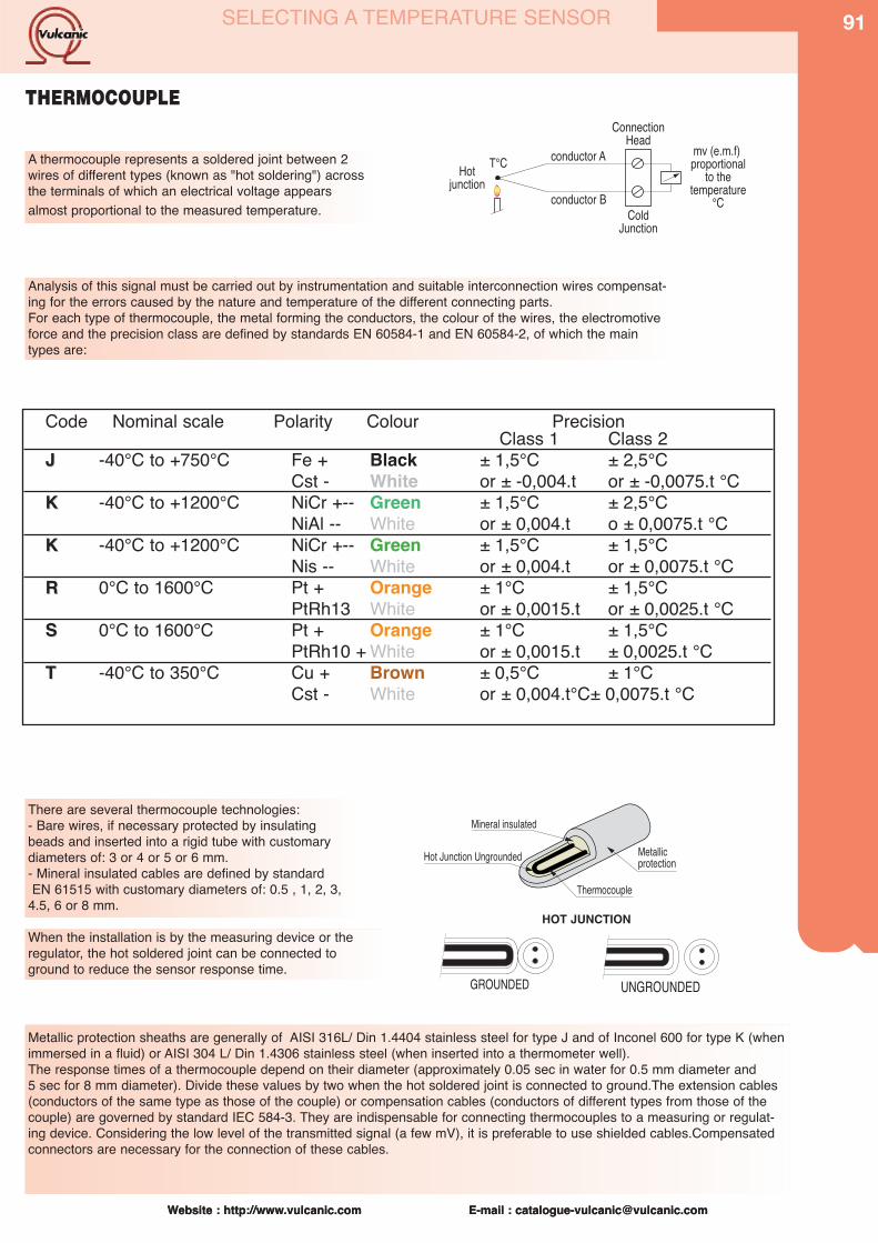
Website : http://www.vulcanic.com E-mail : [email protected]
91
Website : http://www.vulcanic.com E-mail : [email protected]
THERMOCOUPLE
A thermocouple represents a soldered joint between 2wires of different types (known as "hot soldering") acrossthe terminals of which an electrical voltage appearsalmost proportional to the measured temperature.
��������� ��
���������
������������
�� �������������������
�� ��������������
��
�����������
��������������
Analysis of this signal must be carried out by instrumentation and suitable interconnection wires compensat-ing for the errors caused by the nature and temperature of the different connecting parts.For each type of thermocouple, the metal forming the conductors, the colour of the wires, the electromotiveforce and the precision class are defined by standards EN 60584-1 and EN 60584-2, of which the maintypes are:
Code Nominal scale Polarity Colour PrecisionClass 1 Class 2
JJ -40°C to +750°C Fe + Black ± 1,5°C ± 2,5°CCst - White or ± -0,004.t or ± -0,0075.t °C
KK -40°C to +1200°C NiCr +-- Green ± 1,5°C ± 2,5°CNiAl -- White or ± 0,004.t o ± 0,0075.t °C
KK -40°C to +1200°C NiCr +-- Green ± 1,5°C ± 1,5°CNis -- White or ± 0,004.t or ± 0,0075.t °C
RR 0°C to 1600°C Pt + Orange ± 1°C ± 1,5°CPtRh13 White or ± 0,0015.t or ± 0,0025.t °C
SS 0°C to 1600°C Pt + Orange ± 1°C ± 1,5°CPtRh10 + White or ± 0,0015.t ± 0,0025.t °C
TT -40°C to 350°C Cu + Brown ± 0,5°C ± 1°CCst - White or ± 0,004.t°C± 0,0075.t °C
There are several thermocouple technologies:- Bare wires, if necessary protected by insulatingbeads and inserted into a rigid tube with customarydiameters of: 3 or 4 or 5 or 6 mm.- Mineral insulated cables are defined by standardEN 61515 with customary diameters of: 0.5 , 1, 2, 3,
4.5, 6 or 8 mm.
���������������
������ �� ������
�� ������� ��������
���������
When the installation is by the measuring device or theregulator, the hot soldered joint can be connected toground to reduce the sensor response time.
GROUNDED
Metallic protection sheaths are generally of AISI 316L/ Din 1.4404 stainless steel for type J and of Inconel 600 for type K (whenimmersed in a fluid) or AISI 304 L/ Din 1.4306 stainless steel (when inserted into a thermometer well).The response times of a thermocouple depend on their diameter (approximately 0.05 sec in water for 0.5 mm diameter and 5 sec for 8 mm diameter). Divide these values by two when the hot soldered joint is connected to ground.The extension cables(conductors of the same type as those of the couple) or compensation cables (conductors of different types from those of thecouple) are governed by standard IEC 584-3. They are indispensable for connecting thermocouples to a measuring or regulat-ing device. Considering the low level of the transmitted signal (a few mV), it is preferable to use shielded cables.Compensatedconnectors are necessary for the connection of these cables.
HOT JUNCTION
SELECTING A TEMPERATURE SENSOR
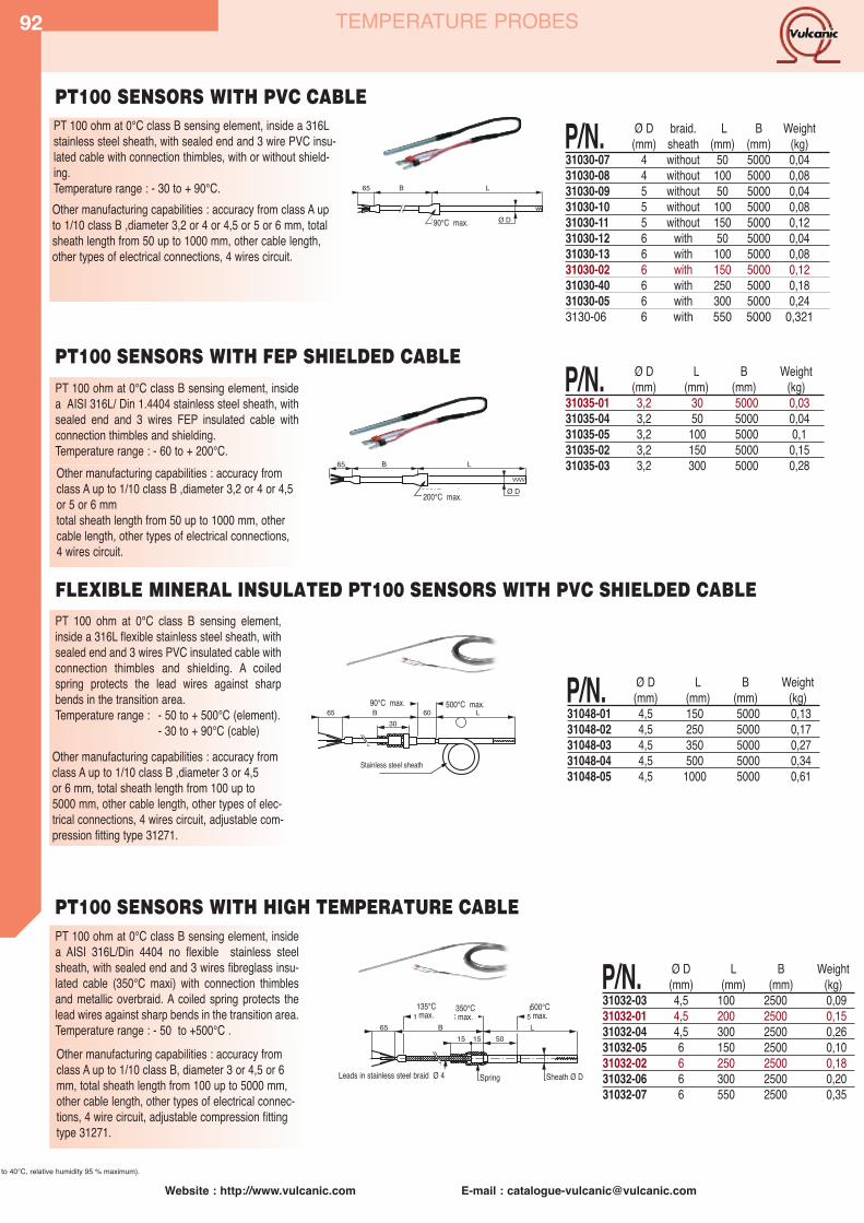
92
Website : http://www.vulcanic.com E-mail : [email protected]
TEMPERATURE PROBES
PT 100 ohm at 0°C class B sensing element, inside a 316Lstainless steel sheath, with sealed end and 3 wire PVC insu-lated cable with connection thimbles, with or without shield-ing. Temperature range : - 30 to + 90°C. �� � �
� ��� � ��
P/N. Ø D braid. L B Weight(mm) sheath (mm) (mm) (kg)
31030-07 4 without 50 5000 0,0431030-08 4 without 100 5000 0,0831030-09 5 without 50 5000 0,0431030-10 5 without 100 5000 0,0831030-11 5 without 150 5000 0,1231030-12 6 with 50 5000 0,0431030-13 6 with 100 5000 0,0831030-02 6 with 150 5000 0,1231030-40 6 with 250 5000 0,1831030-05 6 with 300 5000 0,243130-06 6 with 550 5000 0,321
Other manufacturing capabilities : accuracy from class A upto 1/10 class B ,diameter 3,2 or 4 or 4,5 or 5 or 6 mm, total sheath length from 50 up to 1000 mm, other cable length,other types of electrical connections, 4 wires circuit.
PT 100 ohm at 0°C class B sensing element, insidea AISI 316L/ Din 1.4404 stainless steel sheath, withsealed end and 3 wires FEP insulated cable withconnection thimbles and shielding. Temperature range : - 60 to + 200°C.
P/N. Ø D L B Weight(mm) (mm) (mm) (kg)
31035-01 3,2 30 5000 0,0331035-04 3,2 50 5000 0,0431035-05 3,2 100 5000 0,131035-02 3,2 150 5000 0,1531035-03 3,2 300 5000 0,28
� �
����
����
�� ���
Other manufacturing capabilities : accuracy fromclass A up to 1/10 class B ,diameter 3,2 or 4 or 4,5or 5 or 6 mm total sheath length from 50 up to 1000 mm, othercable length, other types of electrical connections,4 wires circuit.
PT 100 ohm at 0°C class B sensing element,inside a 316L flexible stainless steel sheath, withsealed end and 3 wires PVC insulated cable withconnection thimbles and shielding. A coiledspring protects the lead wires against sharpbends in the transition area. Temperature range : - 50 to + 500°C (element).
- 30 to + 90°C (cable)
P/N. Ø D L B Weight(mm) (mm) (mm) (kg)
31048-01 4,5 150 5000 0,1331048-02 4,5 250 5000 0,1731048-03 4,5 350 5000 0,2731048-04 4,5 500 5000 0,3431048-05 4,5 1000 5000 0,61
��
� ���
��� � �
��
����� ������ ��
FLEXIBLE MINERAL INSULATED PT100 SENSORS WITH PVC SHIELDED CABLE
PT 100 ohm at 0°C class B sensing element, insidea AISI 316L/Din 4404 no flexible stainless steelsheath, with sealed end and 3 wires fibreglass insu-lated cable (350°C maxi) with connection thimblesand metallic overbraid. A coiled spring protects thelead wires against sharp bends in the transition area. Temperature range : - 50 to +500°C .
����� � ���� ����� �� ��� ���� � �
��
�� � �
���������� �����
�� ��
���� ���� ����
P/N. Ø D L B Weight(mm) (mm) (mm) (kg)
31032-03 4,5 100 2500 0,0931032-01 4,5 200 2500 0,1531032-04 4,5 300 2500 0,2631032-05 6 150 2500 0,1031032-02 6 250 2500 0,1831032-06 6 300 2500 0,2031032-07 6 550 2500 0,35
PT100 SENSORS WITH HIGH TEMPERATURE CABLE
Other manufacturing capabilities : accuracy fromclass A up to 1/10 class B, diameter 3 or 4,5 or 6mm, total sheath length from 100 up to 5000 mm,other cable length, other types of electrical connec-tions, 4 wire circuit, adjustable compression fittingtype 31271.
PT100 SENSORS WITH PVC CABLE
PT100 SENSORS WITH FEP SHIELDED CABLE
Other manufacturing capabilities : accuracy fromclass A up to 1/10 class B ,diameter 3 or 4,5 or 6 mm, total sheath length from 100 up to 5000 mm, other cable length, other types of elec-trical connections, 4 wires circuit, adjustable com-pression fitting type 31271.
Leads in stainless steel braid Ø 4 Spring
135°Cmax.
200°C max.
90°C max.
500°C max.90°C max.
Stainless steel sheath
350°Cmax.
500°Cmax.
Sheath Ø D
to 40°C, relative humidity 95 % maximum).

Website : http://www.vulcanic.com E-mail : [email protected]
93TEMPERATURE PROBES
PT 100 ohm at 0°C class B sensing element, insidea AISI 316L/Din 1.4404 flexible stainless steelsheath. Electrical connection by a standard 3 polesmale plug.Temperature range : - 50 to + 500°C (element).
- 10 to + 200°C (connector) . P/N. Ø D L(mm) (mm)
31106-01 4,5 10031106-02 4,5 20031106-03 4,5 30031106-04 4,5 400
Other manufacturing capabilities : accuracy from classA up to 1/10 class B ,diameter 3 or 4,5 or 6 mm, totalsheath length from 100 up to 5000 mm,other types ofelectrical connectors (JAEGER, LEMO...), 4 wires cir-cuit, adjustable compression fitting type 31271..
PT 100 ohm at 0°C class B sensing element, inside aAISI 316L/Din 1.4404 stainless steel sheath. Electricalconnection by a 3 poles terminal block inside an IP 54miniature aluminium head, epoxy painted, with com-pression gland ISO 16. Supplied with or without a 1/2”BSPT threaded fitting, welded below the head.Temperature range : - 50 to + 500°C (sensor)
- 50 to + 80°C (box)
55
60Ø D
L
IP54
P/N. ØD L Connector Weight(mm) (mm) (kg)
31042-08 6 100 without 0,131042-01 6 100 with 0,1631042-04 6 150 without 0,1131042-09 6 150 with 0,231042-02 6 200 without 0,1331042-10 6 200 with 0,2431042-05 6 250 without 0,16
PT100 SENSORS WITH MINIATURE IP54 ALUMINIUM HEAD
Other manufacturing capabilities : accuracy from classA up to 1/10 class B ,diameter 4 or 4,5 or 5 or 6 mm,total sheath length from 50 up to 1000 mm, 4 wires cir-cuit, fastening by sliding flange.
PT 100 ohm at 0°C class B sensing element, insidea AISI 316L/ Din 1.4404 flexible stainless steelsheath. Electrical connection by a 3 poles terminalblock inside an IP 65 aluminium head, epoxy paint-ed, with compression gland for cable dia 4 to 15 mm.Temperature range : - 50 to + 500°C (element)
- 10 to + 80°C (head)
P/N. Ø D L1 L2 Weight(mm) (mm) (mm) (kg)
31022-01 4,5 150 30 0,1231022-02 4,5 200 30 0,1631022-03 4,5 300 30 0,2431022-04 4,5 350 30 0,3031022-05 4,5 500 30 0,3431022-06 4,5 550 30 0,36
FLEXIBLE MINERAL INSULATED PT100 SENSORS WITH IP65 ALUMINIUM HEAD
L1
Ø D
92
100
L2rigide
Single PT sensor, 100 ohm at 0°C, class B, in a flex-ible stainless steel sheath with sealed end and 3 ter-minals in a miniature box (80°C max.) with a ISO 16 gland.- Temperature range : - 100 to + 500°C (sensor),
- 10 to + 80°C (box).Fixing : use a type 31271 compression fitting.
P/N. D L1 L2 Weight(mm) (mm) (mm) (kg)
31023-07 4,5 100 30 0,0831023-08 4,5 200 30 0,1231023-09 4,5 300 30 0,1731023-10 6 300 30 0,2531023-11 6 400 30 0,3031023-12 6 500 30 0,35
FLEXIBLE MINERAL INSULATED PT100 SENSORS WITH IP65 ALUMINIUM HEAD
��
� �
������
��
�
����Other manufacturing capabilities : accuracy from class A
up to 1/10 class B ,diameter 3 or 4,5 or 6 mm, totalsheath length from 100 up to 5000 mm, 4 wires circuit,fastening by compression fitting or mounting flange.
Other manufacturing capabilities : accuracy fromclass A up to 1/10 class B ,diameter 3 or 4,5 or6 mm, total sheath length from 100 up to 5000 mm,4 wires circuit, fastening by compression fitting type31721 , 4/20 mA transmitter installed inside thehead.
60 mmnon-flexible
IP65
IP54
IP54
Ø D
FLEXIBLE MINERAL INSULATED PT100 SENSORS WITH STANDARD MALE PLUG
Ø D

94
Website : http://www.vulcanic.com E-mail : [email protected]
L1
Ø D
L2rigide
92
90
Raccord 1/2" NPT
PT 100 ohm at 0°C class B sensing element, inside a AISI 304L /Din 1.4306 stain-less steel sheath. Electrical connection by a 3 poles terminal block inside an IP 65offset aluminium head, epoxy painted, with compression gland for cable dia 4 to 15mm. Spring loaded terminals, with a 8 mm clearance (the L dimension is correspon-ding to the half compression of the spring) Offset AISI316 L /Din 1.4404 nipple 1/2ʼʼNPT threaded fittingTemperature range : - 50 to + 500°C (element)
- 50 to + 80°C (head)
PT 100 ohm at 0°C class B sensing element, inside a flexible AISI 316L/Din1.4404 stain-less steel sheath. Electrical connection by a 3 poles terminal block inside an IP 65EXPLOSION PROOF head with a compression gland for cable dia 8 mm.1/2ʼʼ NPT threaded fitting welded below the head.temperature range: - 50 to + 500°C (element)
- 20 to + 80°C (head)Usable in hazardous areas (ambient temperature from -20 °C up to 40°C, relative humidity 95 % maximum).Marking II 2 G EEx d IIC T6 Certificate : LCIE 03 Atex 6340
P/N. Ø D L1(mm) (mm)
31045-01 4,5 10031045-02 4,5 20031045-03 4,5 30031045-04 6 10031045-05 6 20031045-06 6 300
PT 100 SENSORS WITH IP65 OFFSET ALUMINIUM HEAD
PT 100 ohm at 0°C class B sensing element, inside a flexible AISI 316L/Din 1.4404stainless steel sheath. Electrical connection by a 3 poles terminal block inside an IP65 stainless steel AISI 316L/Din 1.4404 head, epoxy painted, with compression glandfor cable dia 4 up to 15 mm.1/2ʼʼ NPT threaded fitting welded below the headTemperature range : - 50 to + 500°C (element)
- 50 to + 80°C (head)
FLEXIBLE MINERAL INSULATED PT 100 SENSORS WITH IP65 STAINLESS STEEL HEAD
P/N. Ø D L1(mm) (mm)
31043-10 6 10031043-11 6 20031043-12 6 30031043-13 6 400
P/N. Ø D L1 L2(mm) (mm) (mm)
31045-07 4,5 100 10831045-08 4,5 200 10831045-09 4,5 300 10831045-10 6 100 10831045-11 6 200 10831045-12 6 300 108
PT 100 ohm at 0°C class B sensing element, inside a AISI 304L/Din 1.4306 stainless steel sheath. Electrical connection by a 3 poles ter-minal block inside an IP 65 offset EXPLOSION PROOF head with com-pression gland for cable dia 8 mm. Spring loaded terminals, with a 8 mmclearance (the L dimension is corresponding to the half compression of thespring) Offset AISI316 L/Din 1.4406 nipple 1/2ʼʼ NPT threaded fittingTemperature range : - 50 to + 500°C (element)
- 20 to + 80°C (head)Usable in hazardous areas (ambient temperature from -20 °C up to 40°C, relative humidity 95 % maxi-mum). Marking II 2 G EEx d IIC T6 Certificate : LCIE 03 Atex 6340
Other manufacturing capabilities : accuracy from class A up to 1/10 class B, totalsheath length from 50 up to 1000 mm, offset nipple length 58 or 108 mm, 4 wires cir-cuit, possible fixing nipple union, ATEX approval EEx ia or EEx e, 4/20 mA transmitterinstalled inside the head.
Other manufacturing capabilities : accuracy from class A up to 1/10 class B , diameter3 or 4,5 or 6 mm, total sheath length from 100 up to 5000 mm, 4 wire circuits, 4/20mA transmitter installed inside the head.
Options : transmitter installed inside the head.
1/2" sleeve sch 40in 316L stainless steel
Ø 1/2" NPT
1/2" NPTconnection
Other manufacturing capabilities : accuracy from class A up to 1/10 class B , diameter 3or 4,5 or 6 mm,total sheath length from 50 up to 1000 mm, 4 wire circuits, 4/20 mAtransmitter installed inside the head.
L 104 mm
145
8,0
mm
Fixation 1/2"Npt
Manchette Inox
E
Other manufacturing capabilities : accuracy from class A up to 1/10 classB, total sheath length from 50 up to 1000 mm, offset nipple of 58 or 108mm, 4 wires circuit, fastening nipple union, 4/20 mA.
FLEXIBLE MINERAL INSULATED PT 100 SENSORS WITH EXPLOSION PROOF HEAD
TEMPERATURE PROBES
L 104 mm
145
8,0
mm
Fixation 1/2"Npt
PT 100 SENSORS WITH OFFSET EXPLOSION PROOF HEAD
P/N. Ø D L1(mm) (mm)
31043-15 6 10031043-16 6 15031043-17 6 20031043-18 6 25031043-19 6 30031043-20 6 400
stainless

TEMPERATURE PROBES
L 126
Haut : 51Fixation 2xØ 5,5
5541 P/N. Ø D L(mm) (mm)
31026-01 4,5 20031026-06 4,5 30031026-07 6 30031026-08 6 400
PT 100 ohm at 0°C class B sensing element, inside a flexi-ble AISI 316L/ Din 1.4404 stainless steel sheath. Electricalconnection by a 3 poles terminal block inside a miniatureEXPLOSION PROOF head, with compression gland forcable dia 6 up to 9 mm. : Temperature range : -50 to + 500°C (element)
20 to + 80°C (head)
FLEXIBLE MINERAL INSULATED PT 100 SENSORS WITH MINIATURE
EXPLOSION PROOF HEAD
Other manufacturing capabilities : accuracy from class A up to 1/10 class Bdiameter 3 or 4,5 or 6 mm, total sheath length from 100 up to 5000 mm,4 wires circuit, fastening by compression fitting type 31721.
Height : 51 2x 5,5 Ø fixings
Compact probe for direct screwing in the part tomeasure.PT 100 ohm at 0°C class B sensing element insidea AISI 316 L/Din 1.4404 screw. 3 wires PTFE insu-lated cable with connection thimbles. Temperature range : - 80 to + 200°C
P/N. Ø D Length threaded(mm)
31109-01 1/4”-20 UNF 1131109-02 M8 1631109-03 M10 16
PT 100 ohm at 0°C class B sensing element, inside aPTFE sheath, with sealed end and 3 wires FEP insulat-ed leads with connection thimbles. Supplied with 3 ter-minals for electrical connection on 2,5 mm2 wires. Special design to be used with PTFE heating panel (seeimmersion heaters section).
65 15 30
Ø 5Ø 9,6Ø 12
8000
P/N. Max. Weighttemp. (kg)
26216-01 105°C 0,10PT 100 SENSORS WITH PTFE SHEATH AND FEP LEADS
PT 100 ohm at 0°C class B sensing element, insidea AISI 316L/Din 1.4404 stainless steel sheath, flat-tened to measure the skin temperature of hoses, withsealed end and 3 wires PFE insulated cable withconnection thimbles and shielding.
P/N. Max. B Weighttemp. (mm) (kg)
31180-01 200°C 1000 0,231180-02 200°C 3000 0,4
SCREW PLUG PT100 SENSORS
ROOM AND OUTSIDE ambient AIR TEMPERATURE PT 100 SENSORSRoom sensor : P/N. 31055-01PT 100 ohm at 0°C class B sensing element inside a holedplastic box to IP 20, for wall mounting.Temperature range : - 40 to + 85°CElectrical connection by a 2, 3 or 4 poles terminal blockthrough the bulkhead.
Outside ambient sensor : P/N. 31055-02PT 100 ohm at 0°C class B sensing element inside a plasticbox to IP 65, for wall mounting.Temperature range : - 50 to + 100°CElectrical connection by a 2, 3 or 4 poles terminal bloc, withcompression gland..
PT 100 SENSORS FOR SKIN TEMPERATURE MEASUREMENT
Website : http://www.vulcanic.com E-mail : [email protected]
95
Usable in hazardous areas (ambient temperature from -20 °C up to 40°C, relative humidity 95 % maximum).Marking II 2 G EEx d IIC T6 Certificate : LCIE 03 Atex 6337
REF. Probet Ø D Rqnge(mm) (°C)
31711-05 PT100 sensor 10,2 -50/+20031711-02 Thermocouple K 10,2 -50/+280
Mainly intended for the measure of surfaces temperature onmachine contact or thermic dissipators, Sensistive elementmounted in a teminal connector FASTON Insulated coductors teflon/teflon cable length 1m.2 Cables for TC or 3 conductive isolated wires for RTD 100
Ø D
B 50
35Ø 4
6
2,5
65
FASTON PROBES
On request :Others fixing diameterAvailable for Atex areas (dust or gas)

96
Website : http://www.vulcanic.com E-mail : [email protected]
Sensitive elements Pt 100 Ω, Class B.AWG 28 wire outputs Teflon linedOne adhesive side for attachment.Thickness : 0,5 mm on element - 0,7 mm on wires.Options on request :• Without adhesive (-200°C / +200°C).• Wire length > 1000 mm.
7,6
7,6
1000
LAMINAR Platinum PROBES 7,6 mmx7,6 mm
TEMPERATURE PROBES
P/N. Sensor Accuracy. Nr of Isolator Time Temperaturewires constant range
31132-51 • Pt 100 Ω to 0°C ±0,12 Ω 3 Polymide insulated + Alu face 0,15 s -20/+177°C*31132-52 • Pt 100 Ω to 0°C ±0,12 Ω 4 Polymide insulated + Alu face 0,15 s -20/+177°C*31132-53 • Pt 100 Ω to 0°C ±0,12 Ω 2 Polymide insulated + Alu face 0,15 s -20/+177°C** For assembly without adhesive, operating temperature range : -200°C/+200°C
Sensitive elements Pt 100 Ω or Pt 1000ΩAWG 26 wire outputs Teflon linedOne adhesive side for attachment.Thickness : 2 mm Options on request :• Without adhesive (-50°C / +200°C).• Wire length > 1000 mm.
15
5
1000
LAMINAR Platinum PROBES 5 mm x 15 mm
P/N. Sensor Accuracy. Nr of Isolator Time Temperaturewires constant range
31132-01 • Pt 100 Ω to 0°C ±0,12 Ω 3 Polymide insulated 1 s -20/+177°C*31132-02 • Pt 100 Ω to 0°C ±0,12 Ω 4 Polymide insulated 1 s -20/+177°C** * For assembly without adhesive, operating temperature : -50°C/+200°C
MINIATURE FLANGED Platinum PROBES Ø 4,8 x 6,4 mm
� ���
���� ���
���
� ���
Sensitive element: PT 100 ohm at 0°C Class BVessel of tinned light alloyOutput by insulated wire with PTFE length 900 mmThese probes can be used whenever space is at apremium.Other possibilities on requestWire outputs without shielding braidCopper probes 100 ohmNickel probes 120 ohmMiniature sensors equipped with an antifriction end.In this case, the load temperatures become:Resistance probe: -50/+260°CWire outputs: without shielding braidWire length >900 mm
Ø 5 x 6,1
13
����
����
Spring P/N 31123-99 - Stainless steel- Compressed length: 5.6 mm
Clip P/N: 31123-98 for single or double sensors with Teflon wire- Anticorrosion-treated carbon steel- To be used for drilling diameter: 7.92 + 0.2 m
�����
���
Clip P/N: 31123-97 for single or double sensorswith Teflon wires + shielding braid- Anticorrosion treated carbon steel- To be used on drilling diameter: 7.92 + 0.2 m
������
���������� ��
��������� �������
������� ��������
�����
��������� � ���� �����
Recommended installation:Use spring P/N 31123-99 and clip P/N 31123-98 or P/N 31123-97 to retainthe miniature flanged probe in its hole
P/N. Captor Accuracy. Probe Temperature Nr Section Timerange lead of lead mm2 constant
31123-04 • Platinum 100 Ω to 0°C ±0,12 Ω Simple -50/+150°C 1 x 3 0,227 4 s31123-09 • Platinum 100 Ω to 0°C ±0,12 Ω Double -50/+150°C 2 x 3 0,089 4 s
FASTENING ACCESSORIES

Website : http://www.vulcanic.com E-mail : [email protected]
97
Website : http://www.vulcanic.com E-mail : [email protected]
THERMOCOUPLES
Class 2 thermocouple with an ungrounded hot junction,inside a 316 L stainless steel sheath, with sealed endand 2 wires high temperature cable with metallic over-braid and connection thimbles Maximum operation temperature : 350°C.
P/N. J type P/N. K type Ø D L B Weight(mm) (mm) (mm) (kg)
31066-01 • 31066-11 4,5 50 2500 0,0531066-03 • 31066-13 4,5 100 2500 0,131066-04 31066-14 4,5 200 2500 0,231066-05 • 31066-15 4,5 300 2500 0,331066-02 • 31066-12 6 150 2500 0,0731066-06 31066-16 6 250 2500 0,1231066-07 31066-17 6 550 2500 0,25Other L or B lengths to order
65 B
Ø D
L
200°C maxi
THERMOCOUPLES WITH HIGH TEMPERATURE EXTENSION CABLE
Class 2 thermocouple with an ungrounded hot junction,inside a flexible mineral insulated 316L stainless steelsheath, with sealed end and 2 wires PVC insulatedcable (90°C maxi) and connection thimbles
L
Ø D
65 40B
90°C max
P/N. T/C Ø D Max. B L Weighttype (mm) temp. (mm) (mm) (kg)
31061-01 K 3 1100°C 2500 500 0,0731061-02 K 3 1100°C 2500 1000 0,131061-09 J 1 750°C 2500 500 0,0531061-10 J 1 750°C 2500 1000 0,0931061-12 J 2 750°C 2500 500 0,0531061-11 J 2 750°C 2500 1000 0,131061-19 K 1 750°C 2500 500 0,0531061-20 K 1 750°C 2500 1000 0,0931061-22 K 2 750°C 2500 500 0,0531061-21 K 2 750°C 2500 1000 0,1
Class 2 thermocouple with an ungrounded hot junctioninside a flexible mineral insulated 316L (Type J) or Inconel600 (Type K) stainless steel sheath, with sealed end andhigh temperature extension cable with metallic overbraid.Max. temperature: 600°C (J type) and 1000°C (K type).Max. cable temperature: 200°C. Fastening: use a type31271 compression fitting.
L
Ø D
65 402000
xxxxxxxxxxxxxxxxxx200°C max
P/N. TCJ P/N. TCK ØD (mm) L (mm)31080-02 31214-02 0,5 15031080-11 31214-11 1 20031080-12 31214-12 1 25031080-18 31214-18 1,5 15031080-20 31214-20 1,5 25031080-23 31214-23 2 20031080-24 31214-24 2 25031080-31 31214-31 3 20031080-32 31214-32 3 250
FLEXIBLE MINERAL INSULATED THERMOCOUPLES WITH HIGH TEMPERATUREEXTENSION CABLE
FLEXIBLE MINERAL INSULATED THERMOCOUPLES WITH PVC EXTENSION CABLE
Other manufacturing capabilities : accuracy class 1,total sheath length from 50 up to 1000 mm, other cablelength, bended sensor, possible fixing by compressionfitting or mounting flange, other thermocouple type R, S,T...
Other manufacturing capabilities : accuracy class 1,diameter 0,5 or 1 or 2 or 3 or 4,5 or 6 or 8 mm, totalflexible sheath length from 100 up to 5000 mm, othercable length, adjustable compression fitting type 31271,other thermocouple types R, S, T..., ATEX approval EExia.
Other manufacturing capabilities : accuracy class 1,diameter 0,5 or 1 or 2 or 3 or 4,5 or 6 or 8 mm, total flexible sheath length from 100 up to 5000 mm, othercable length, adjustable compression fitting type 31271.. R S T thermocouple type EExia, other thermocouple types R, S, T..., ATEX approval EEx ia.
Class 2 thermocouple with an ungrounded hot junctioninside a flexible mineral insulated 316L (Type J) or Inconel600 (Type K) stainless steel sheath, with an electrical plug,and with an optional shielded PVC extension cable.Maximum operation temperature : 600°C (TC J) or 1000°C(TCK), 200°C on the connector and 90°C on the cable.
++ +---
62 60 G ØD50
15 25x13Femelle Mâle
Raccord optionnel
2500 LU monté
P/N. TCJ P/N. TCK ØD A) U Optional Weight (mm) (mm) (mm) connector (kg)
31064-01 31064-11 3 500 106 with 0,0931064-02 31064-12 3 1000 106 with 0,1131064-03 31064-13 3 1500 106 with 0,1331064-04 31064-08 3 100 0 without 0,0931064-05 31064-09 3 200 0 without 0,0931064-06 31064-10 3 300 0 without 0,0931064-07 31064-14 3 400 0 without 0,1031064-19 31064-15 6 100 0 without 0,0931064-20 31064-16 6 200 0 without 0,0931064-23 31064-17 6 300 0 without 0,1031064-25 31064-18 6 400 0 without 0,10
FLEXIBLE MINERAL INSULATED THERMOCOUPLES WITH CONNECTOR AND PVC EXTENSIONCABLE
U connected
Optional connectorFemale MaleA = “L” if there is no connector.
A = “G” if there is connector.
Class 2 thermocouple with an ungrounded hot junctioninside a 304L (Type J) or Inconel 600 (Type K) stainlesssteel sheath. Electrical connection by a 2 poles terminalblock inside an IP 65 offset aluminium head, epoxy painted,with compression gland for cable dia 4 to 15 mm. Springloaded terminals, with a 8 mm clearance (the L1 dimensionis corresponding to the half compression of the spring)Offset 316 L nipple 1/2ʼʼ NPT threaded fittingMax operating temperature : 600°C (TC J) or 1000°C (TCK),and 80°C on the head
P/N. J type P/N. K type Ø D L1 L2(mm) (mm) (mm)
31075-01 31075-05 3 100 10831075-02 31075-06 3 150 10831075-03 31075-07 3 200 10831075-04 31075-08 3 250 108
31075-09 6 100 10831075-10 6 150 10831075-11 6 200 10831075-12 6 250 108
THERMOCOUPLES WITH IP65 OFFSET ALUMINIUM HEAD
Stainlesssteel sleeve

98
Website : http://www.vulcanic.com E-mail : [email protected]
L 104 mm
145
8,0
mm
Fixation 1/2"Npt
Class 2 thermocouple with an ungrounded hot junc-tion inside a flexible mineral insulated 316L (Type J)or Inconel 600 (Type K) stainless steel sheath.Electrical connection by a 2 poles terminal blockinside an IP 65 EXPLOSION PROOF head with acompression gland for cable dia 8 mm.1/2ʼʼ NPT threaded fitting welded below the headMaximum operating temperature : 600°C (TC J) or1000°C (TCK), and 80°C on the head
P/N. J type P/N. K type Ø D L(mm) (mm)
31068-10 31068-13 3 10031068-11 31068-14 3 15031068-12 31068-15 3 200
31068-16 6 10031068-17 6 15031068-18 6 200
Class 2 thermocouple with an ungrounded hot junc-tion inside a 304L (Type J) or Inconel 600 (Type K)stainless steel sheath. Electrical connection by a 2poles terminal block inside an IP 65 EXPLOSIONPROOF head with a compression gland for cable dia8 mm.Offset 316 L nipple 1/2ʼʼ NPT threaded fittingMaximum operating temperature : 600°C (TC J) or1000°C (TCK), and 80°C on the head.
P/N. J type P/N. K type Ø D L1 L2(mm) (mm) (mm)
31075-13 31075-17 3 100 10831075-14 31075-18 3 150 10831075-15 31075-19 3 200 10831075-16 31075-20 3 250 108
31075-21 6 100 10831075-22 6 150 10831075-23 6 200 10831075-24 6 250 108
THERMOCOUPLES WITH OFFSET EXPLOSION PROOF HEAD
Other manufacturing capabilities : accuracy class 1, diameter 3 or 4,5 or 6 or 8 mm, total flexible sheath length from 100 up to 5000 mm, other thermocouple types R, S, T..., 4/20 mA transmitter installed inside the head.
Other manufacturing capabilities : accuracy class 1, diameter 3 or 4,5 or 6 mm, total sheath length from 100 up to 1000 mm, offset nipple of 58 or 108 mm, other thermocouple types R, S, T..., 4/20 mA transmitter installed inside the head.
FLEXIBLE MINERAL INSULATED THERMOCOUPLES WITH EXPLOSION PROOF HEAD
L 104 mm
145
8,0
mm
Fixation 1/2"Npt
Manchette Inox
E
THERMOCOUPLES
Class 2 thermocouple with an ungrounded hot junctioninside a 316L (Type J) or Inconel 600 (Type K) stain-less steel sheath. Electrical connection by a 2 poleterminal block inside an IP54 miniature aluminiumhead, epoxy painted, with compression gland N°9.Maximum operating temperature : 600°C (TC J) or1000°C (TCK) and 80°C on the head.
55
60Ø D
L
IP53
P/N. J type P/N. K type Ø D L Weight(mm) (mm) (kg)
31067-01 31067-03 • 8 150 0,1331067-05 31067-13 8 250 0,1531067-02 31067-04 • 8 300 0,1731067-11 31067-14 8 350 0,1931067-12 31067-15 8 550 0,31
THERMOCOUPLES WITH MINIATURE IP54 ALUMINIUM HEAD
Class 2 thermocouple with an ungrounded hot junction insidea 316L (Type J) or Inconel 600 (Type K) stainless steelsheath. Electrical connection by a 2 pole terminal block insidean IP 65 aluminium head, epoxy painted, with compressiongland for cable dia 4 to 15 mm.Maximum operation temperature : 600°C (TC J) or 1000°C(TCK) and 80°C on the head
P/N. K type Ø D L Weight(mm) (mm) (kg)
31068-61 4,5 150 0,0631068-62 4,5 300 0,1231068-63 4,5 550 0,231068-64 6 150 0,0731068-65 6 200 0,0931068-66 6 250 0,1131068-67 6 300 0,1431068-68 6 350 0,1731068-69 6 550 0,26
L
Ø D
92
90
Fixation 1/2" NPT
FLEXIBLE MINERAL INSULATED THERMOCOUPLES WITH IP65 ALUMINIUM HEAD
Other manufacturing capabilities : accuracy class 1,diame-ter 3 or 4,5 or 6 or 8 mm, total flexible sheath length from100 up to 5000 mm,, adjustable compression fitting type31271, other thermocouple types R, S, T.. ATEX approvalEEx ia.or EEx e, 4/20 mA transmitter installed inside thehead.
1/2" NPT connection
Usable in hazardous areas (ambient temperature from -20 °C up to 40°C, relative humidity 95 % maximum).Marking II 2 G EEx d IIC T6Certificate : LCIE 03 Atex 6340
Usable in hazardous areas (ambient temperature from -20 °C up to 40°C, relative humidity 95 % maximum).Marking II 2 G EEx d IIC T6Certificate : LCIE 03 Atex 6340
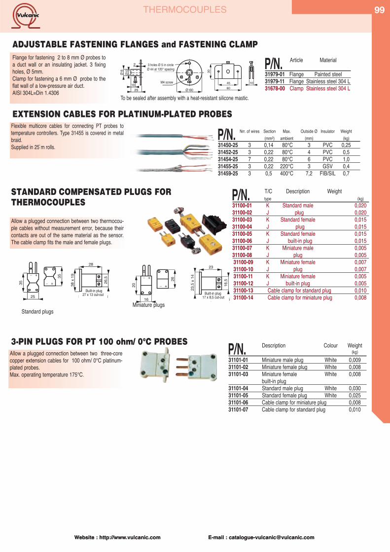
Website : http://www.vulcanic.com E-mail : [email protected]
99
Website : http://www.vulcanic.com E-mail : [email protected]
THERMOCOUPLES
Allow a plugged connection between two thermocou-ple cables without measurement error, because theircontacts are out of the same material as the sensor.The cable clamp fits the male and female plugs.
P/N. T/C Description Weighttype (kg)
31100-01 K Standard male 0,02031100-02 J plug 0,02031100-03 K Standard female 0,01531100-04 J plug 0,01531100-05 K Standard female 0,01531100-06 J built-in plug 0,01531100-07 K Miniature male 0,00531100-08 J plug 0,00531100-09 K Miniature female 0,00731100-10 J plug 0,00731100-11 K Miniature female 0,00531100-12 J built-in plug 0,00531100-13 Cable clamp for standard plug 0,01031100-14 Cable clamp for miniature plug 0,008
+
35
25
28
EmbaseDécoupe 27 x 13
_+_ 38
x 19
26,535 +_
+_20
26
16
23
EmbaseDécoupe 17 x 8,5
23,5
x 14
16,5
Standard plugsMiniature plugs
STANDARD COMPENSATED PLUGS FORTHERMOCOUPLES
27 x 13 cut-outBuilt-in plug
17 x 8,5 cut-outBuilt-in plug
30
45 1060
Flange for fastening 2 to 8 mm Ø probes toa duct wall or an insulating jacket. 3 fixingholes, Ø 5mm.Clamp for fastening a 6 mm Ø probe to theflat wall of a low-pressure air duct.AISI 304L=Din 1.4306
P/N. Article Material
31979-01 Flange Painted steel31979-11 Flange Stainless steel 304 L31678-00 Clamp Stainless steel 304 LØ 60
1025
Ø16
Ø10
2 3 trous Ø 5 surØ 44 à 120°
Vis M4
ADJUSTABLE FASTENING FLANGES and FASTENING CLAMP
Flexible multicore cables for connecting PT probes totemperature controllers. Type 31455 is covered in metalbraid.Supplied in 25`m rolls.
P/N. Nrr. of wires Section Max. Outside Ø Insulator Weight(mm2) ambient (mm) (kg)
31450-25 3 0,14 80°C 3 PVC 0,2531452-25 3 0,22 80°C 4 PVC 0,531454-25 7 0,22 80°C 6 PVC 1,031455-25 3 0,22 220°C 3 GSV 0,431459-25 3 0,5 400°C 7,2 FIB/SIL 0,7
EXTENSION CABLES FOR PLATINUM-PLATED PROBES
To be sealed after assembly with a heat-resistant silicone mastic.
3 holes Ø 5 in circleØ 44 at 120° spacing
M4 screw
Allow a plugged connection between two three-corecopper extension cables for 100 ohm/ 0°C platinum-plated probes.Max. operating temperature 175°C.
P/N. Description Colour Weight(kg)
31101-01 Miniature male plug White 0,00931101-02 Miniature female plug White 0,00831101-03 Miniature female White 0,008
built-in plug31101-04 Standard male plug White 0,03031101-05 Standard female plug White 0,02531101-06 Cable clamp for miniature plug 0,00831101-07 Cable clamp for standard plug 0,010
3-PIN PLUGS FOR PT 100 ohm/ 0°C PROBES
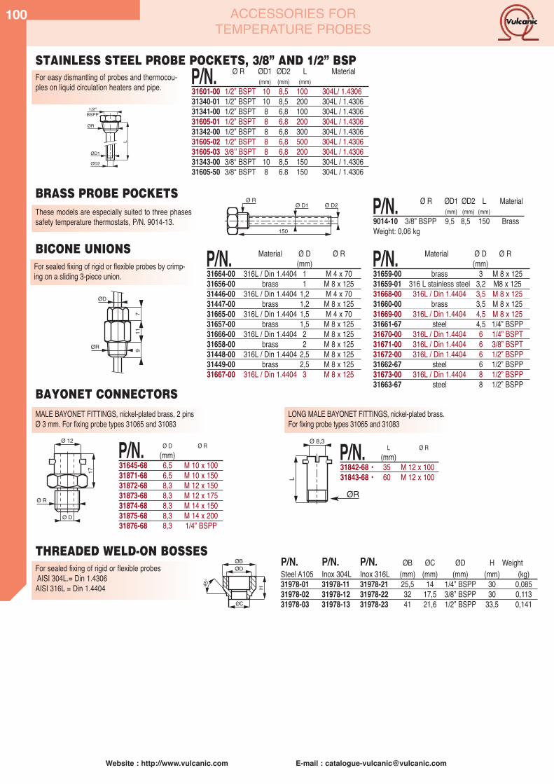
100
Website : http://www.vulcanic.com E-mail : [email protected]
ACCESSORIES FORTEMPERATURE PROBES
1/2"BSPP
ØRL
ØD1
ØD2
For easy dismantling of probes and thermocou-ples on liquid circulation heaters and pipe. P/N. Ø R ØD1 ØD2 L Material
(mm) (mm) (mm)31601-00 1/2” BSPT 10 8,5 100 304L/ 1.430631340-01 1/2” BSPT 10 8,5 200 304L / 1.430631341-00 1/2” BSPT 8 6,8 100 304L / 1.430631605-01 1/2” BSPT 8 6,8 200 304L / 1.430631342-00 1/2” BSPT 8 6,8 300 304L / 1.430631605-02 1/2” BSPT 8 6,8 500 304L / 1.430631605-03 3/8ʼʼ BSPT 8 6,8 200 304L / 1.430631343-00 3/8“ BSPT 10 8,5 150 304L / 1.430631605-50 3/8“ BSPT 8 6.8 150 304L / 1.4306
These models are especially suited to three phasessafety temperature thermostats, P/N. 9014-13.
150
Ø D1 Ø D2Ø R P/N. Ø R ØD1 ØD2 L Material
(mm) (mm) (mm)9014-10 3/8” BSPP 9,5 8,5 150 BrassWeight: 0,06 kg
ØR
ØD
911
7
P/N. Material Ø D Ø R(mm)
31659-00 brass 3 M 8 x 12531659-01 316 L stainless steel 3,2 M8 x 12531668-00 316L / Din 1.4404 3,5 M 8 x 12531660-00 brass 3,5 M 8 x 12531669-00 316L / Din 1.4404 4,5 M 8 x 12531661-67 steel 4,5 1/4” BSPP31670-00 316L / Din 1.4404 6 1/4” BSPT31671-00 316L / Din 1.4404 6 3/8” BSPT31672-00 316L / Din 1.4404 6 1/2” BSPP31662-67 steel 6 1/2” BSPP31673-00 316L / Din 1.4404 8 1/2” BSPP31663-67 steel 8 1/2” BSPP
For sealed fixing of rigid or flexible probes by crimp-ing on a sliding 3-piece union.
BICONE UNIONS P/N. Material Ø D Ø R(mm)
31664-00 316L / Din 1.4404 1 M 4 x 7031656-00 brass 1 M 8 x 12531446-00 316L / Din 1.4404 1,2 M 4 x 7031447-00 brass 1,2 M 8 x 12531665-00 316L / Din 1.4404 1,5 M 4 x 7031657-00 brass 1,5 M 8 x 12531666-00 316L / Din 1.4404 2 M 8 x 12531658-00 brass 2 M 8 x 12531448-00 316L / Din 1.4404 2,5 M 8 x 12531449-00 brass 2,5 M 8 x 12531667-00 316L / Din 1.4404 3 M 8 x 125
For sealed fixing of rigid or flexible probesAISI 304L.= Din 1.4306AISI 316L = Din 1.4404
P/N. P/N. P/N. ØB ØC ØD H WeightSteel A105 Inox 304L Inox 316L (mm) (mm) (mm) (mm) (kg)31978-01 31978-11 31978-21 25,5 14 1/4” BSPP 30 0,08531978-02 31978-12 31978-22 32 17,5 3/8” BSPP 30 0,11331978-03 31978-13 31978-23 41 21,6 1/2” BSPP 33,5 0,141
H
ØB
ØC
45°
ØD
MALE BAYONET FITTINGS, nickel-plated brass, 2 pinsØ 3 mm. For fixing probe types 31065 and 31083
17
Ø 12
Ø R
Ø D
P/N. Ø D Ø R(mm)
31645-68 6,5 M 10 x 10031871-68 6,5 M 10 x 15031872-68 8,3 M 12 x 15031873-68 8,3 M 12 x 17531874-68 8,3 M 14 x 15031875-68 8,3 M 14 x 20031876-68 8,3 1/4” BSPP
L
Ø 8,3
LONG MALE BAYONET FITTINGS, nickel-plated brass.For fixing probe types 31065 and 31083
P/N. L Ø R(mm)
31842-68 • 35 M 12 x 10031843-68 • 60 M 12 x 100
ØR
BRASS PROBE POCKETS
BAYONET CONNECTORS
THREADED WELD-ON BOSSES
STAINLESS STEEL PROBE POCKETS, 3/8” AND 1/2” BSP

Website : http://www.vulcanic.com E-mail : [email protected]
101
Website : http://www.vulcanic.com E-mail : [email protected]
CONVERTERS ANDMEASUREMENT UNITS
PROGRAMMABLE CONVERTERS FOR ROD HEAD P/N. 31712-00
The 31712-00 type is a digital converter for a rod head using the 2-wire technique Input : PT 100 ohm or thermocouple J K T R S B or mv Output : 4/20 mA programmable for scale, response time and input type Linearization, cold solder compensation and line resistance compensation incorporatedinto the converter. Power supply between 9 and 40 Vdc with load resistance at 24 Vdc 750 ohm Operating temperature range: -30 °C + 85 °C Attaching centre distance 33 mm, 7 mm central role to accommodate sensor wiresConnection by screw-on terminal with 2.5 mm2 capacity. Indication of power supply presence by LEDProtection against polarity reversal Protection from shock and vibration (silicone coating resin)
Other production : version with galvanic insulation, hart protocol
P/N. Ø R ØD1 ØD2 L Material(mm) (mm) (mm)
31390-01 1/2” BSPT 10 8,5 100 316L / 1.440431391-01 1/2” BSPT 10 8,5 200 316L / 1.440431392-00 1/2”BSPT 8 6,8 100 316L / 1.440431393-00 1/2” BSPT 8 6,8 200 316L / 1.440431394-00 1/2” BSPT 8 6,8 300 316L / 1.440431395-00 1/2” BSPT 8 6,8 500 316L / 1.440431396-00• 3/8ʼʼ BSPT 8 6,8 200 316L / 1.440431396-50• 3/8ʼʼ BSPT 8 6,8 150 316L / 1.440431397-00 3/8“BSPT 10 8,5 150 316L / 1.4404
PROGRAMMABLE FIELD CONVERTERS WITH LOCAL DISPLAY P/N.31713-00The 31713-00 type is a 4/20 mA programmable converter using the two-wire technique with alocal display assembled in an IP 65 epoxy painted aluminum case Input : thermocouple JKTRSB with PT 100 Ohm probe . Output : 4/20 mA programmable for scale, response time and input type LCD display of extended temperature (4 digits) Resolution 10 000 points Linearization, cold solder compensation and line resistance compensation incorporated into theconverter. Power supply between 12 and 40 Vdc with load resistance at 24 Vdc 550 ohm Operating temperature range: -20 °C + 60 °C Connection by screw-on terminal with 2.5 mm2 capacity. Protection against polarity reversal IP 65 epoxy painted aluminum case with electrical output by PG 16 g cable gland for 7/12 mm Process assembly by 1/2" cylindrical gas threading
Assembly : - DIN rail unit: 23 x 100 x 120 mmConfigurable input : - Pt100, thermocouple
- mV, V, mA, ohm- sensor power supply, potentiometer, stress gauge - frequency: TTL, Namur, NPN, PNP, …….
Special functions : - square root extraction- customised linearisation
Configurable output : - 1 current output 0...4.... 20 mA, voltage 0 to 10 VSecond isolated output : - option (CNL 35L/S2)Configurable relays (as an option) : - max 4 relays, potential free
- detection of probe breakage and of measurement thresholdPower supply : - 20 to 265 Vac-dc, or 9 to 30 Vdc on requestInsulation : - input/output 1500 Vac power supplyParameter settings : - RS232 link or front panel
Assembly : - plug-in type, case 96 x 96 x 150 mmConfigurable inputs : - : 4,8,12 inputs, according to the P/N above (identical configuration for all
the channels).- Pt100 2 or 3 wires, linearised- Compensated and linearised thermocouple- mV, mA, ohm
Configurable alarms : - 2 configurable alarms for each channels- detection of probe breakage and of measurement threshold
Relays : - 2 relays for all the channels- inverter relay, potential free
Display : - 4 digits LCD 7 segments, 10 000 points- display of measurement, fixed point, scrolling, alarm threshold adjust
mentsPower supply : - 230 Vac: other voltage to be defined on orderInsulation : - power supply/input/relay 1500 Vac
- input/output 250 VacParameter settings : - RS232 link (cord not supplied, on request)
MULTI GENERAL MEASUREMENT UNITS TYPE 31714
GENERAL-PURPOSE DIGITAL CONVERTERS P/N.31715-00
Application: centralised supervisionand monitoring of temperatureAdvantage: compact, low cost.
Application: measurement of indus-trial signals, temperature, speed,weight, position, flow rate, etcAdvantage: wide range of applica-tions fully configurable by the user
P/N. Input nbr.
31714-04 431714-08 831714-12 12
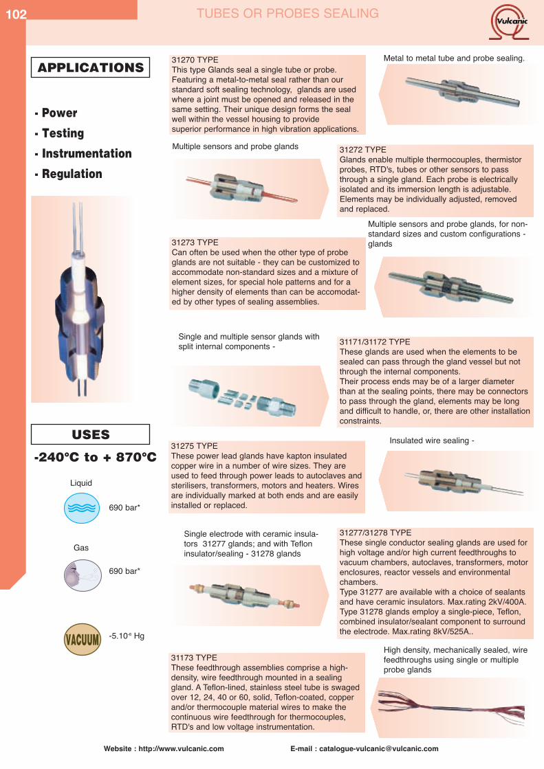
102
Website : http://www.vulcanic.com E-mail : [email protected]
31270 TYPEThis type Glands seal a single tube or probe.Featuring a metal-to-metal seal rather than our standard soft sealing technology, glands are usedwhere a joint must be opened and released in thesame setting. Their unique design forms the sealwell within the vessel housing to provide superior performance in high vibration applications.
31273 TYPECan often be used when the other type of probeglands are not suitable - they can be customized toaccommodate non-standard sizes and a mixture ofelement sizes, for special hole patterns and for ahigher density of elements than can be accomodat-ed by other types of sealing assemblies.
31173 TYPEThese feedthrough assemblies comprise a high-density, wire feedthrough mounted in a sealinggland. A Teflon-lined, stainless steel tube is swagedover 12, 24, 40 or 60, solid, Teflon-coated, copperand/or thermocouple material wires to make thecontinuous wire feedthrough for thermocouples,RTD's and low voltage instrumentation.
31277/31278 TYPEThese single conductor sealing glands are used forhigh voltage and/or high current feedthroughs tovacuum chambers, autoclaves, transformers, motorenclosures, reactor vessels and environmentalchambers.Type 31277 are available with a choice of sealantsand have ceramic insulators. Max.rating 2kV/400A.Type 31278 glands employ a single-piece, Teflon,combined insulator/sealant component to surroundthe electrode. Max.rating 8kV/525A..
31272 TYPEGlands enable multiple thermocouples, thermistorprobes, RTD's, tubes or other sensors to passthrough a single gland. Each probe is electricallyisolated and its immersion length is adjustable.Elements may be individually adjusted, removedand replaced.
31171/31172 TYPEThese glands are used when the elements to besealed can pass through the gland vessel but notthrough the internal components.Their process ends may be of a larger diameterthan at the sealing points, there may be connectorsto pass through the gland, elements may be longand difficult to handle, or, there are other installationconstraints.
31275 TYPEThese power lead glands have kapton insulatedcopper wire in a number of wire sizes. They areused to feed through power leads to autoclaves andsterilisers, transformers, motors and heaters. Wiresare individually marked at both ends and are easilyinstalled or replaced.
- Power
- Testing
- Instrumentation
- Regulation
APPLICATIONS
USES
VACUUM
Liquid
Gas
-240°C to + 870°C
690 bar*
690 bar*
-5.10-6 Hg
Metal to metal tube and probe sealing.
Multiple sensors and probe glands
Multiple sensors and probe glands, for non-standard sizes and custom configurations - glands
Single and multiple sensor glands withsplit internal components -
Insulated wire sealing -
Single electrode with ceramic insula-tors 31277 glands; and with Tefloninsulator/sealing - 31278 glands
High density, mechanically sealed, wirefeedthroughs using single or multipleprobe glands
TUBES OR PROBES SEALING
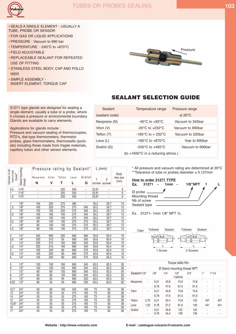
Website : http://www.vulcanic.com E-mail : [email protected]
103TUBES OR PROBES SEALING
• SEALS A SINGLE ELEMENT - USUALLY A TUBE, PROBE OR SENSOR• FOR GAS OR LIQUID APPLICATIONS• PRESSURE : Vacuum to 690 bar• TEMPERATURE : -240°C to +870°C• FIELD ADJUSTABLE• REPLACEABLE SEALANT FOR REPEATED
USE OF FITTING• STAINLESS STEEL BODY, CAP AND FOLLO
WER• SIMPLE ASSEMBLY -
INSERT ELEMENT, TORQUE CAP
1 Screw 2 ScrewsLL
SealantFollower Follower SealantCaps
Pressure
31271 type glands are designed for sealing asingle element, usually a tube or a probe, whereit crosses a pressure or environmental boundary.Glands are available to carry elements.
Applications for glands include : Pressure and vacuum sealing of thermocouples,RTDʼs, dial-type thermometers, thermistorprobes, glass thermometers, thermowells (pock-ets) including those made from fragile materials,capillary tubes and other sensor elements.
SEALANT SELECTION GUIDE
Sealant Temperature range Pressure range(sealant code) at 20°CNeoprene (N) -40°C to +93°C Vacuum to 345barViton (V) -20°C to +232°C Vacuum to 690barTeflon (T) -185°C to + 232°C Vacuum to 220barLava (L) -185°C to +870°C 1bar to 690barGrafoil (G) -240°C to +495°C Vacuum to 690bar
(to +1650°C in a reducing atmos.)
0,5 1/16” - - 220 550 - 23,81 - 91 1/16” - - 220 550 - 23,81 - 91,5 1/16” - - 220 550 - 23,81 - 9
1 1/8” 165 220 275 385 - 30,2 39,7 131,5 1/8” 165 220 275 275 345 30,2 39,7 132 1/8” 165 165 220 275 345 30,2 39,7 132,5 1/8” 165 165 165 275 345 30,2 39,7 133 1/8” 165 165 165 275 345 30,2 39,7 133,5 1/8” 80 100 100 275 275 30,2 39,7 134 1/8” 80 100 100 275 275 30,2 39,7 134,5 1/8” 80 100 100 275 275 30,2 39,7 13
3 1/4” 345 690 220 690 690 50,8 60,4 193,5 1/4” 220 310 65 690 345 50,8 60,4 194 1/4” 220 310 165 690 345 50,8 60,4 194,5 1/4” 220 310 165 690 345 50,8 60,4 195 1/4” 165 205 80 690 275 50,8 60,4 195,5 1/4” 165 205 80 690 275 50,8 60,4 196 1/4” 165 205 80 690 275 50,8 60,4 19
5 1/2” 100 100 165 690 345 63,5 82,5 266 1/2” 100 100 165 690 345 63,5 82,5 267 1/2” 80 80 135 690 345 63,5 82,5 268 1/2” 80 80 135 690 345 63,5 82,5 269 1/2” 80 35 95 690 220 63,5 82,5 269,52 1/2” 80 35 95 690 220 63,5 82,5 26
12,7 3/4” 60 60 100 345 165 73 92 3813 3/4” 55 55 55 275 165 73 92 3814 3/4” 55 55 55 275 165 73 92 3815 3/4” 55 55 55 275 165 73 92 3815,87 3/4” 55 55 55 275 165 73 92 3816 3/4” 55 55 55 275 165 73 92 3817 3/4” 55 55 55 275 165 73 92 38
Diame
ter of
ele-
ment
of se
althr
ead**
Gla
nd m
ounti
ngthr
ead
P r e s s u r e r a t i n g b y S e a l a n t *N e o p r e n e V i t o n Te f l o n L a v a G r a f o i l
N V T L G
L (mm)
1screw
2screw
BodyHex size
(mm)
* All pressure and vacuum rating are determined at 20°C**Tolerance of tube or probes diameter ± 0,127mm
How to order 31271 TYPE Ex. 31271 - 1mm - 1/8”NPT 1 L
Ø probeMounting threadNb of screwSealant type
Ex. 31271- 1mm 1/8” NPT 1L
Torque table NmØ Gland mounting thread NPT
Sealant1/16” 1/8” 1/4” 1/2” 3/4” 1” 1”1/4material
Neoprene - 6,21 40,8 74,8 74,8 - -6,78 47,6 81,6 81,6 - -
Viton - 6,21 40,8 74,8 74,8 - -6,78 47,6 81,6 81,6 - -
Teflon 0,79 6,21 20,4 74,8 122 407 407Lava 1,02 6,78 27,2 81,6 136 441 441Grafoil - 6,21 46,6 122 122 - -
- 6,78 54,4 136 136 - -
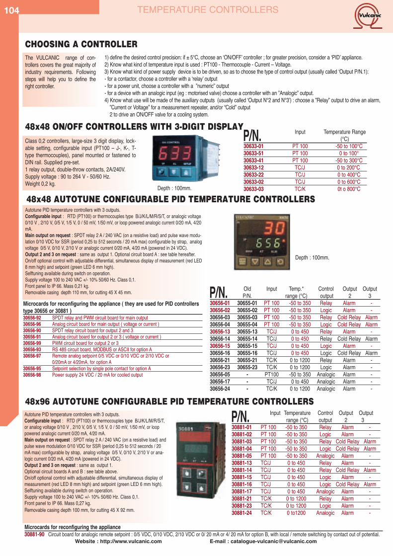
104
Website : http://www.vulcanic.com E-mail : [email protected]
TEMPERATURE CONTROLLERS
Autotune PID temperature controllers with 3 outputs. Configurable input : RTD (PT100) or thermocouples type B/J/K/L/M/R/S/T,or analog voltage 0/10 V , 2/10 V, 0/5 V, 1/5 V, 0 / 50 mV, 1/50 mV, or looppowered analogic current 0/20 mA, 4/20 mA. Main output on request : SPDT relay 2 A / 240 VAC (on a resistive load) andpulse wave modulation 0/10 VDC for SSR (period 0,25 to 512 seconds / 20mA max) configurable by strap, analog voltage 0/5 V, 0/10 V, 2/10 V or ana-logic current 0/20 mA, 4/20 mA (powered in 24 VDC). Output 2 and 3 on request : same as output 1.Optional circuit boards A and B : see table above. On/off optional control with adjustable differential, simultaneous display ofmeasurement (red LED 8 mm high) and setpoint (green LED 6 mm high).Selftuning available during switch on operation. Supply voltage 100 to 240 VAC +/- 10% 50/60 Hz. Class 0,1. Front panel to IP 66. Mass 0,27 kg. Removable casing depth 100 mm, for cutting 45 X 92 mm.
P/N. Input Temperature Control Output Outputrange (°C) output 2 3
30881-01 PT 100 -50 to 350 Relay Alarm -30881-02 PT 100 -50 to 350 Logic Alarm -30881-03 PT 100 -50 to 350 Relay Cold Relay Alarm30881-04 PT 100 -50 to 350 Logic Cold Relay Alarm30881-05 PT 100 -50 to 350 Analogic Alarm -30881-13 TC/J 0 to 450 Relay Alarm -30881-14 TC/J 0 to 450 Relay Cold Relay Alarm30881-15 TC/J 0 to 450 Logic Alarm -30881-16 TC/J 0 to 450 Logic Cold Relay Alarm30881-17 TC/J 0 to 450 Analogic Alarm -30881-21 TC/K 0 to 1200 Relay Alarm -30881-23 TC/K 0 to 1200 Logic Alarm -30881-24 TC/K 0 to1200 Analogic Alarm -
48x96 AUTOTUNE CONFIGURABLE PID TEMPERATURE CONTROLLERS
Microcards for reconfiguring the appliance30881-90 Circuit board for analogic remote setpoint : 0/5 VDC, 0/10 VDC, 2/10 VDC or 0/ 20 mA or 4/ 20 mA for option B, with local / remote switching by contact out of potential.
Class 0,2 controllers, large-size 3 digit display, lock-able setting, configurable input (PT100 – J-, K-, T-type thermocouples), panel mounted or fastened toDIN rail. Supplied pre-set.1 relay output, double-throw contacts, 2A/240V.Supply voltage : 90 to 264 V - 50/60 Hz.Weight 0,2 kg.
P/N. Input Temperature Range(°C)
30633-01 PT 100 -50 to 100°C30633-51 PT 100 0 to 100°30633-41 PT 100 -50 to 300°C30633-12 TC/J 0 to 200°C30633-22 TC/J 0 to 400°C30633-02 TC/J 0 to 600°C30633-03 TC/K 0t o 800°CDepth : 100mm.
The VULCANIC range of con-trollers covers the great majority ofindustry requirements. Followingsteps will help you to define theright controller.
1) define the desired control precision: if ± 5°C, choose an ʻON/OFF ̓controller ; for greater precision, consider a ʻPID ̓appliance.2) Know what kind of temperature input is used : PT100 - Thermocouple - Current – Voltage.3) Know what kind of power supply device is to be driven, so as to choose the type of control output (usually called ʻOutput P/N.1):- for a contactor, choose a controller with a ʻrelay ̓output- for a power unit, choose a controller with a ”numeric” output - for a device with an analogic input (eg : motorised valve) choose a controller with an ”Analogic” output.4) Know what use will be made of the auxiliary outputs (usually called ʻOutput N°2 and N°3ʼ) : choose a ”Relay” output to drive an alarm,
”Current or Voltage” for a measurement repeater, and/or “Cold” output 2 to drive an ON/OFF valve for a cooling system.
CHOOSING A CONTROLLER
Autotune PID temperature controllers with 3 outputs. Configurable input : RTD (PT100) or thermocouples type B/J/K/L/M/R/S/T, or analogic voltage0/10 V , 2/10 V, 0/5 V, 1/5 V, 0 / 50 mV, 1/50 mV, or loop powered analogic current 0/20 mA, 4/20mA. Main output on request : SPDT relay 2 A / 240 VAC (on a resistive load) and pulse wave modu-lation 0/10 VDC for SSR (period 0,25 to 512 seconds / 20 mA max) configurable by strap, analogvoltage 0/5 V, 0/10 V, 2/10 V or analogic current 0/20 mA, 4/20 mA (powered in 24 VDC). Output 2 and 3 on request : same as output 1. Optional circuit board A : see table hereafter. On/off optional control with adjustable differential, simultaneous display of measurement (red LED8 mm high) and setpoint (green LED 6 mm high). Selftuning available during switch on operation. Supply voltage 100 to 240 VAC +/- 10% 50/60 Hz. Class 0,1. Front panel to IP 66. Mass 0,21 kg. Removable casing depth 110 mm, for cutting 45 X 45 mm.
48x48 AUTOTUNE CONFIGURABLE PID TEMPERATURE CONTROLLERS
P/N. Old Input Temp.* Control Output OutputP/N. range (°C) output 2 3
30656-01 30655-01 PT 100 -50 to 350 Relay Alarm -30656-02 30655-02 PT 100 -50 to 350 Logic Alarm -30656-03 30655-03 PT 100 -50 to 350 Relay Cold Relay Alarm30656-04 30655-04 PT 100 -50 to 350 Logic Cold Relay Alarm30656-13 30655-13 TC/J 0 to 450 Relay Alarm -30656-14 30655-14 TC/J 0 to 450 Relay Cold Relay Alarm30656-15 30655-15 TC/J 0 to 450 Logic Alarm -30656-16 30655-16 TC/J 0 to 450 Logic Cold Relay Alarm30656-21 30655-21 TC/K 0 to 1200 Relay Alarm -30656-23 30655-23 TC/K 0 to 1200 Logic Alarm -30656-05 - PT100 -50 to 350 Analogic Alarm -30656-17 - TC/J 0 to 450 Analogic Alarm -30656-24 - TC/K 0 to 1200 Analogic Alarm -
Microcards for reconfiguring the appliance ( they are used for PID controllerstype 30656 or 30881 )30656-92 SPDT relay and PWM circuit board for main output30656-96 Analog circuit board for main output ( voltage or current )30656-90 SPDT relay circuit board for output 2 and 330656-91 Analog circuit board for output 2 or 3 ( voltage or current )30656-99 PWM circuit board for output 2 or 330656-93 RS 485 circuit board, MODBUS or ASCII for option A30656-97 Remote analog setpoint 0/5 VDC or 0/10 VDC or 2/10 VDC or
0/20mA or 4/20mA, for option A30656-95 Setpoint selection by single pole contact for option A30656-98 Power supply 24 VDC / 20 mA for cooled output
Depth : 100mm.
48x48 ON/OFF CONTROLLERS WITH 3-DIGIT DISPLAY
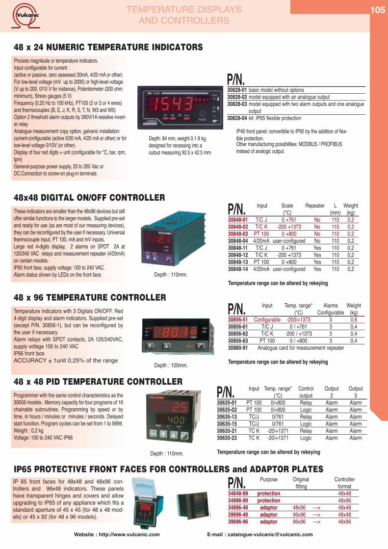
Website : http://www.vulcanic.com E-mail : [email protected]
105TEMPERATURE DISPLAYSAND CONTROLLERS
IP 65 front faces for 48x48 and 48x96 con-trollers and 96x48 indicators. These panelshave transparent hinges and covers and allowupgrading to IP65 of any appliance which fits astandard aperture of 45 x 45 (for 48 x 48 mod-els) or 45 x 92 (for 48 x 96 models).
P/N. Purpose Original Controllerfitting format
34848-99 protection 48x4834896-99 protection 48x9634896-48 adaptor 48x96 ---> 48x4839696-48 adaptor 96x96 ---> 48x4839696-96 adaptor 96x96 ---> 48x96
Programmer with the same control characteristics as the30656 models . Memory capacity for four programs of 16chainable subroutines. Programming by speed or bytime, in hours / minutes or minutes / seconds. Delayedstart function. Program cycles can be set from 1 to 9999.Weight : 0,2 kgVoltage: 100 to 240 VAC IP66
P/N. Input Temp. range* Control Output Output(°C) output 2 3
30635-01 PT 100 0/+800 Relay Alarm Alarm30635-02 PT 100 0/+800 Logic Alarm Alarm30635-13 TC/J 0/761 Relay Alarm Alarm30635-15 TC/J 0/761 Logic Alarm Alarm30635-21 TC K -20/+1371 Relay Alarm Alarm30635-23 TC K -20/+1371 Logic Alarm Alarm
Temperature range can be altered by rekeyingDepth : 110mm.
Temperature indicators with 3 Digitals ON/OFF. Red4-digit display and alarm indicators. Supplied pre-set(except P/N. 30856-1), but can be reconfigured bythe user if necessary.Alarm relays with SPDT contacts, 2A 120/240VAC,supply voltage 100 to 240 VACIP66 front faceACCURACY ± 1unit 0,25% of the range
P/N. Input Temp. range* Alarms Weight (°C) Configurable (kg)
30856-51 Configurable -200/+1373 3 0,630856-61 T/C J 0 / +761 3 0,430856-62 T/C K -200 / +1373 3 0,430856-63 PT 100 0 / +800 3 0,430880-91 Analogue card for measurement repeater
Temperature range can be altered by rekeyingDepth : 100mm.
P/N.30828-01 basic model without options30828-02 model equipped with an analogue output30828-03 model equipped with two alarm outputs and one analogue
output30828-04 kit: IP65 flexible protection
These indicators are smaller than the 48x96 devices but stilloffer similar functions to the larger models. Supplied pre-setand ready for use (as are most of our measuring devices),they can be reconfigured by the user if necessary. Universalthermocouple input, PT 100, mA and mV inputs.Large red 4-digits display, 2 alarms on SPDT 2A at120/240 VAC relays and measurement repeater (4/20mA)on certain models.IP65 front face, supply voltage: 100 to 240 VAC.Alarm status shown by LEDs on the front face.
P/N. Input Scale Repeater L Weight(°C) (mm) (kg)
30848-01 T/C J 0 +761 No 110 0,230848-02 T/C K -200 +1373 No 110 0,230848-03 PT 100 0 +800 No 110 0,230848-04 4/20mA user-configured No 110 0,230848-11 T/C J 0 +761 Yes 110 0,230848-12 T/C K -200 +1373 Yes 110 0,230848-13 PT 100 0 +800 Yes 110 0,230848-14 4/20mA user-configured Yes 110 0,2
Temperature range can be altered by rekeying
48x48 DIGITAL ON/OFF CONTROLLER
Depth : 110mm.
IP65 PROTECTIVE FRONT FACES FOR CONTROLLERS and ADAPTOR PLATES
48 x 48 PID TEMPERATURE CONTROLLER
Process magnitude or temperature indicators.Input configurable for current :(active or passive, zero assessed 20mA, 4/20 mA or other)For low-level voltage (mV up to 2000) or high-level voltage(V up to 200, 0/10 V for instance), Potentiometer (200 ohmminimum), Stress gauges (5 V)Frequency (0.25 Hz to 100 kHz), PT100 (2 or 3 or 4 wires)and thermocouples (B, E, J, K, R, S, T, N, W3 and W5)Option 2 threshold alarm outputs by 260V/1A resistive invert-er relayAnalogue measurement copy option, galvanic installation:current-configurable (active 0/20 mA, 4/20 mA or other) or forlow-level voltage 0/10V (or other).Display of four red digits + unit (configurable for °C, bar, rpm,lpm)General-purpose power supply, 20 to 265 Vac orDC.Connection to screw-on plug-in terminals
48 x 24 NUMERIC TEMPERATURE INDICATORS
48 x 96 TEMPERATURE CONTROLLER
IP40 front panel: convertible to IP65 by the addition of flex-ible protection.Other manufacturing possibilities: MODBUS / PROFIBUSinstead of analogic output.
Depth: 84 mm, weight 0.1 8 kg,designed for recessing into acutout measuring 92.5 x 42.5 mm.
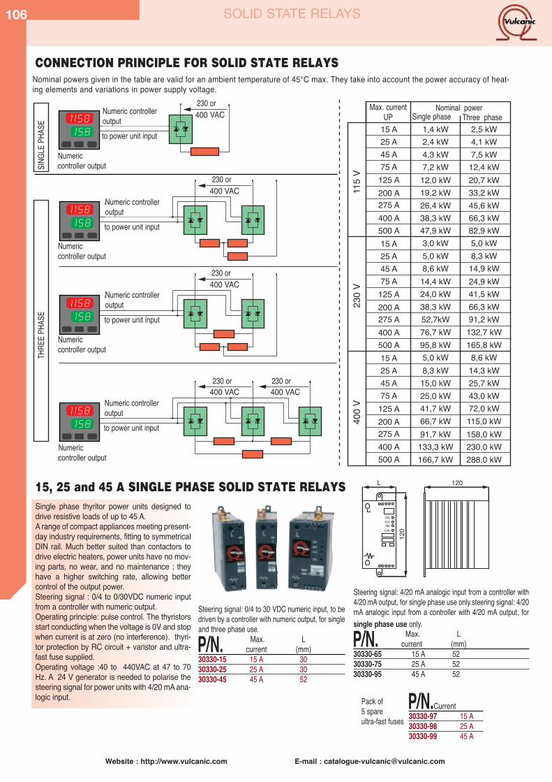
106
Website : http://www.vulcanic.com E-mail : [email protected]
SOLID STATE RELAYS
Single phase thyritor power units designed todrive resistive loads of up to 45 A.A range of compact appliances meeting present-day industry requirements, fitting to symmetricalDIN rail. Much better suited than contactors todrive electric heaters, power units have no mov-ing parts, no wear, and no maintenance ; theyhave a higher switching rate, allowing bettercontrol of the output power.Steering signal : 0/4 to 0/30VDC numeric inputfrom a controller with numeric output.Operating principle: pulse control. The thyristorsstart conducting when the voltage is 0V and stopwhen current is at zero (no interference). thyri-tor protection by RC circuit + varistor and ultra-fast fuse supplied.Operating voltage :40 to 440VAC at 47 to 70Hz. A 24 V generator is needed to polarise thesteering signal for power units with 4/20 mA ana-logic input.
CONNECTION PRINCIPLE FOR SOLID STATE RELAYS
Steering signal: 0/4 to 30 VDC numeric input, to bedriven by a controller with numeric output, for singleand three phase use.
P/N. Max. Lcurrent (mm)
30330-15 15 A 3030330-25 25 A 3030330-45 45 A 52
Steering signal: 4/20 mA analogic input from a controller with4/20 mA output, for single phase use only.steering signal: 4/20mA analogic input from a controller with 4/20 mA output, forsingle phase use only.
P/N. Max. Lcurrent (mm)
30330-65 15 A 5230330-75 25 A 5230330-95 45 A 52
P/N.Current30330-97 15 A30330-98 25 A30330-99 45 A
ONS/CHB
CAL
L 120
120
230 ou400 VACde la sortie logique
du régulateur versl'entrée de l'unité
de puissanceRégulateur àsortie logique
230 ou400 VAC
de la sortie logiquedu régulateur versl'entrée des unités
de puissanceRégulateur àsortie logique
230 ou400 VAC
de la sortie logiquedu régulateur versl'entrée des unités
de puissanceRégulateur àsortie logique
230 ou400 VAC
230 ou400 VAC
de la sortie logiquedu régulateur versl'entrée des unités
de puissanceRégulateur àsortie logique
MON
OPHA
SETR
IPHA
SE
Intensitémaxi UP mono
Puissance nominaletri
115
V23
0 V
400
V
15 A 1,4 kW 2,5 kW2,4 kW 4,1 kW4,3 kW 7,5 kW7,2 kW 12,4 kW
12,0 kW 20,7 kW19,2 kW 33,2 kW26,4 kW 45,6 kW38,3 kW 66,3 kW47,9 kW 82,9 kW3,0 kW 5,0 kW5,0 kW 8,3 kW8,6 kW 14,9 kW
14,4 kW 24,9 kW24,0 kW 41,5 kW38,3 kW 66,3 kW52,7kW 91,2 kW76,7 kW 132,7 kW95,8 kW 165,8 kW5,0 kW 8,6 kW8,3 kW 14,3 kW
15,0 kW 25,7 kW25,0 kW 43,0 kW41,7 kW66,7 kW 115,0 kW91,7 kW 158,0 kW
133,3 kW 230,0 kW166,7 kW 288,0 kW
72,0 kW
25 A45 A75 A
125 A200 A275 A400 A500 A15 A25 A45 A75 A
125 A200 A275 A400 A500 A15 A25 A45 A75 A
125 A200 A275 A400 A500 A
15, 25 and 45 A SINGLE PHASE SOLID STATE RELAYS
Pack of 5 spare ultra-fast fuses
Nominal powers given in the table are valid for an ambient temperature of 45°C max. They take into account the power accuracy of heat-ing elements and variations in power supply voltage.
Numeric controlleroutputto power unit input
Numericcontroller output
Numericcontroller output
Numericcontroller output
Numericcontroller output
Numeric controlleroutputto power unit input
Numeric controlleroutputto power unit input
Numeric controlleroutputto power unit input
SINGL
E PHA
SETH
REE P
HASE
230 or Max. currentUP
Nominal powerSingle phase Three phase
230 or
230 or
230 or 230 or
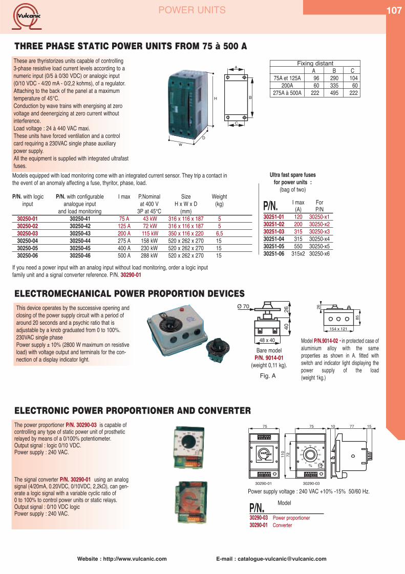
Website : http://www.vulcanic.com E-mail : [email protected]
107
Ultra fast spare fusesfor power units :
(bag of two)
POWER UNITS
These are thyristorizes units capable of controlling3-phase resistive load current levels according to anumeric input (0/5 à 0/30 VDC) or analogic input(0/10 VDC - 4/20 mA - 0/2,2 kohms), of a regulator.Attaching to the back of the panel at a maximumtemperature of 45°C.Conduction by wave trains with energising at zerovoltage and deenergizing at zero current withoutinterference.Load voltage : 24 à 440 VAC maxi.These units have forced ventilation and a controlcard requiring a 230VAC single phase auxiliarypower supply.All the equipment is supplied with integrated ultrafastfuses.
A
C
B
P/N. I max For(A) P/N
30251-01 120 30250-x130251-02 200 30250-x230251-03 315 30250-x330251-04 315 30250-x430251-05 550 30250-x530251-06 315x2 30250-x6
Models equipped with load monitoring come with an integrated current sensor. They trip a contact inthe event of an anomaly affecting a fuse, thyritor, phase, load.
If you need a power input with an analog input without load monitoring, order a logic inputfamily unit and a signal converter reference. P/N. 30290-01
P/N. with logic P/N. with configurable I max P.Nominal Size Weightinput analogue input at 400 V H x W x D (kg)
and load monitoring 3P at 45°C (mm)30250-01 30250-41 75 A 43 kW 316 x 116 x 187 530250-02 30250-42 125 A 72 kW 316 x 116 x 187 530250-03 30250-43 200 A 115 kW 350 x 116 x 220 6,530250-04 30250-44 275 A 158 kW 520 x 262 x 270 1530250-05 30250-45 400 A 230 kW 520 x 262 x 270 1530250-06 30250-46 500 A 288 kW 520 x 262 x 270 15
THREE PHASE STATIC POWER UNITS FROM 75 à 500 A
Fixing distantA B C
75A et 125A 96 290 104200A 60 335 60
275A à 500A 222 495 222
wD
H
This device operates by the successive opening andclosing of the power supply circuit with a period ofaround 20 seconds and a psychic ratio that is adjustable by a knob graduated from 0 to 100%.230VAC single phasePower supply ± 10% (2800 W maximum on resistiveload) with voltage output and terminals for the con-nection of a display indicator light.
The power proportioner P/N. 30290-03 is capable ofcontrolling any type of static power unit of prostheticrelayed by means of a 0/100% potentiometer.Output signal : logic 0/10 VDC.Power supply : 240 VAC.
The signal converter P/N. 30290-01 using an analogsignal (4/20mA, 0.20VDC, 0/10VDC, 2,2kΩ), can gen-erate a logic signal with a variable cyclic ratio of0 to 100% to control power units or static relays. Output signal : 0/10 VDC logicPower supply : 240 VAC.
2640
48 x 40
Ø 70 26
85
154 x 121
Bare modelP/N. 9014-01
(weight 0,11 kg).
Model P/N.9014-02 • in protected case ofaluminium alloy with the same properties as shown in A. fitted withswitch and indicator light displaying thepower supply of the load(weight 1kg.)
504030
20
100
6070
80
90100%
110
72
75 7710 1575
30290-01 30290-03
ELECTRONIC POWER PROPORTIONER AND CONVERTER
ELECTROMECHANICAL POWER PROPORTION DEVICES
Power supply voltage : 240 VAC +10% -15% 50/60 Hz.
P/N. Model
30290-03 Power proportioner30290-01 Converter
Fig. A
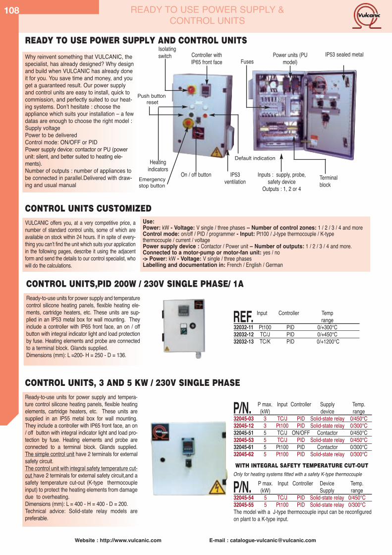
108
Website : http://www.vulcanic.com E-mail : [email protected]
READY TO USE POWER SUPPLY &CONTROL UNITS
VULCANIC offers you, at a very competitive price, anumber of standard control units, some of which areavailable on stock within 24 hours. If in spite of every-thing you canʼt find the unit which suits your applicationin the following pages, describe it using the adjacentform and send the details to our control specialist, whowill do the calculations.
Ready-to-use units for power supply and tempera-ture control silicone heating panels, flexible heatingelements, cartridge heaters, etc. These units aresupplied in an IP55 metal box for wall mounting.They include a controller with IP65 front face, an on/ off button with integral indicator light and load pro-tection by fuse. Heating elements and probe areconnected to a terminal block. Glands supplied. The simple control unit have 2 terminals for externalsafety circuit.The control unit with integral safety temperature cut-out have 2 terminals for external safety circuit,and asafety temperature cut-out (K-type thermocoupleinput) to protect the heating elements from damagedue to overheating.Dimensions (mm): L = 400 - H = 400 - D = 200.Technical advice: Solid-state relay models are preferable.
P/N. P max. Input Controller Supply Temp.(kW) device range
32045-03 3 TC/J PID Solid-state relay 0/450°C32045-12 3 Pt100 PID Solid-state relay 0/300°C32045-51 5 TC/J ON/OFF Contactor 0/450°C32045-53 5 TC/J PID Solid-state relay 0/450°C32045-61 5 Pt100 PID Contactor 0/300°C32045-62 5 Pt100 PID Solid-state relay 0/300°C
Why reinvent something that VULCANIC, thespecialist, has already designed? Why designand build when VULCANIC has already doneit for you. You save time and money, and youget a guaranteed result. Our power supplyand control units are easy to install, quick tocommission, and perfectly suited to our heat-ing systems. Donʼt hesitate : choose theappliance which suits your installation – a fewdatas are enough to choose the right model :Supply voltagePower to be deliveredControl mode: ON/OFF or PIDPower supply device: contactor or PU (powerunit: silent, and better suited to heating ele-ments).Number of outputs : number of appliances tobe connected in parallel.Delivered with draw-ing and usual manual
Isolatingswitch Controller with
IP65 front faceIP53 sealed metal Power units (PU
model)
Terminalblock
Fuses
Inputs : supply, probe,safety device
Outputs : 1, 2 or 4
Heatingindicators
On / off button IP53 ventilation
READY TO USE POWER SUPPLY AND CONTROL UNITS
Use:Power: kW - Voltage: V single / three phases – Number of control zones: 1 / 2 / 3 / 4 and moreControl mode: on/off / PID / programmer - Input: Pt100 / J-type thermocouple / K-type thermocouple / current / voltagePower supply device : Contactor / Power unit – Number of outputs: 1 / 2 / 3 / 4 and more.Connected to a motor-pump or motor-fan unit: yes / no-> Power: kW - Voltage: V single / three phasesLabelling and documentation in: French / English / German
CONTROL UNITS CUSTOMIZED
P/N. P max. Input Controller Device Temp.(kW) Supply range
32045-54 5 TC/J PID Solid-state relay 0/450°C32045-55 5 Pt100 PID Solid-state relay 0/300°CThe model with a J-type thermocouple input can be reconfiguredon plant to a K-type input.
Push buttonreset
Emergency stop button
Default indication
CONTROL UNITS, 3 AND 5 KW / 230V SINGLE PHASE
Ready-to-use units for power supply and temperaturecontrol silicone heating panels, flexible heating ele-ments, cartridge heaters, etc. These units are sup-plied in an IP53 metal box for wall mounting. Theyinclude a controller with IP65 front face, an on / offbutton with integral indicator light and load protectionby fuse. Heating elements and probe are connectedto a terminal block. Glands supplied.Dimensions (mm): L =200- H = 250 - D = 136.
CONTROL UNITS,PID 200W / 230V SINGLE PHASE/ 1A
WITH INTEGRAL SAFETY TEMPERATURE CUT-OUTOnly for heating systems fitted with a safety K-type thermocouple
REF. Input Controller Temprange
32032-11 Pt100 PID 0/+300°C32032-12 TC/J PID 0/+450°C32032-13 TC/K PID 0/+1200°C
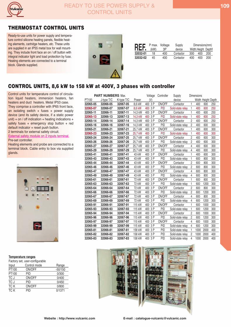
Website : http://www.vulcanic.com E-mail : [email protected]
109READY TO USE POWER SUPPLY &CONTROL UNITS
Control units for temperature control of circula-tion liquid heaters, immersion heaters, fanheaters and duct heaters. Metal IP53 case.They comprise a controller with IP65 front face,an isolating switch + fuses + power supplydevice (and its safety device, if a static powerunit) + on / off indication + heating indications +safety fuses + emergency stop button + reddefault indicator + reset push button.2 terminals for external safety circuit.External safety module on 2 inputs terminal.Pre-set controller.Heating elements and probe are connected to aterminal block. Cable entry to box via suppliedglands.
CONTROL UNITS, 8,6 kW to 158 kW at 400V, 3 phases with controller
PART NUMBERS Max. Voltage Controller Supply DimensionsPT100 J-type T/C K-type T/C Power (V) device Width Height Depth32065-05 32066-05 32067-05 8,6 kW 400 3 P ON/OFF Contactor 1 400 600 25032065-07 32066-07 32067-07 8,6 kW 400 3 P PID Solid-state relay 1 400 600 25032065-11 32066-11 32067-11 14,3 kW 400 3 P ON/OFF Contactor 1 400 600 25032065-13 32066-13 32067-13 14,3 kW 400 3 P PID Solid-state relay 1 400 600 25032065-14 32066-14 32067-14 14,3 kW 400 3 P ON/OFF Contactor 2 400 600 25032065-16 32066-16 32067-16 14,3 kW 400 3 P PID Solid-state relay 2 400 600 30032065-21 32066-21 32067-21 25,7 kW 400 3 P ON/OFF Contactor 1 400 600 30032065-23 32066-23 32067-23 25,7 kW 400 3 P PID Solid-state relay 1 400 600 30032065-24 32066-24 32067-25 25,7 kW 400 3 P ON/OFF Contactor 2 400 600 30032065-26 32066-26 32067-26 25,7 kW 400 3 P PID Solid-state relay 2 400 600 30032065-27 32066-27 32067-27 25,7 kW 400 3 P ON/OFF Contactor 4 400 600 30032065-29 32066-29 32067-29 25,7 kW 400 3 P PID Solid-state relay 4 400 600 30032065-41 32066-41 32067-41 43 kW 400 3 P ON/OFF Contactor 1 400 600 30032065-43 32066-43 32067-43 43 kW 400 3 P PID Solid-state relay 1 600 800 30032065-44 32066-44 32067-44 43 kW 400 3 P ON/OFF Contactor 2 600 800 30032065-46 32066-46 32067-46 43 kW 400 3 P PID Solid-state relay 2 600 800 30032065-47 32066-47 32067-47 43 kW 400 3 P ON/OFF Contactor 4 600 800 30032065-49 32066-49 32067-49 43 kW 400 3 P PID Solid-state relay 4 600 800 30032065-61 32066-61 32067-61 72 kW 400 3 P ON/OFF Contactor 1 600 800 30032065-63 32066-63 32067-63 72 kW 400 3 P PID Solid-state relay 1 600 1200 30032065-64 32066-64 32067-64 72 kW 400 3 P ON/OFF Contactor 2 600 800 30032065-66 32066-66 32067-66 72 kW 400 3 P PID Solid-state relay 2 600 1200 30032065-67 32066-67 32067-67 72 kW 400 3 P ON/OFF Contactor 4 600 800 30032065-69 32066-69 32067-69 72 kW 400 3 P PID Solid-state relay 4 600 1200 30032065-91 32066-91 32067-91 115 kW 400 3 P ON/OFF Contactor 1 600 1000 30032065-93 32066-93 32067-93 115 kW 400 3 P PID Solid-state relay 1 600 1200 30032065-94 32066-94 32067-94 115 kW 400 3 P ON/OFF Contactor 2 600 1000 30032065-96 32066-96 32067-96 115 kW 400 3 P PID Solid-state relay 2 600 1200 30032065-97 32066-97 32067-97 115 kW 400 3 P ON/OFF Contactor 4 600 1000 30032065-99 32066-99 32067-99 115 kW 400 3 P PID Solid-state relay 4 600 1200 30032065-81 32066-81 32067-81 158 kW 400 3 P PID Solid-state relay 1 1000 2000 40032065-82 32066-82 32067-82 158 kW 400 3 P PID Solid-state relay 2 1000 2000 40032065-83 32066-83 32067-83 158 kW 400 3 P PID Solid-state relay 4 1000 2000 400
Temperature rangesFactory set, user-configurableInput Control mode RangePT100 ON/OFF -50/150PT100 PID 0/300TC J ON/OFF 0/400TC J PID 0/450TC K ON/OFF 0/800TC K PID 0/1371
THERMOSTAT CONTROL UNITSReady-to-use units for power supply and tempera-ture control silicone heating panels, flexible heat-ing elements, cartridge heaters, etc. These unitsare supplied in an IP55 metal box for wall mount-ing. They include front face an on / off button withintegral indicator light and load protection by fuse.Heating elements are connected to a terminalblock. Glands supplied.
REF. P max. Voltage Supply Dimensions(mm)(kW) 3P device Width.Height Depthf
32032-01 18 400 Contactor 300 400 20032032-02 45 400 Contactor 400 400 200
RELAY MB TYPESERIES MS200
TP-108-2 SERIES
TA201 SERIES
LOW AND MEDIUMINSTRUMENT TRANSFORMERS
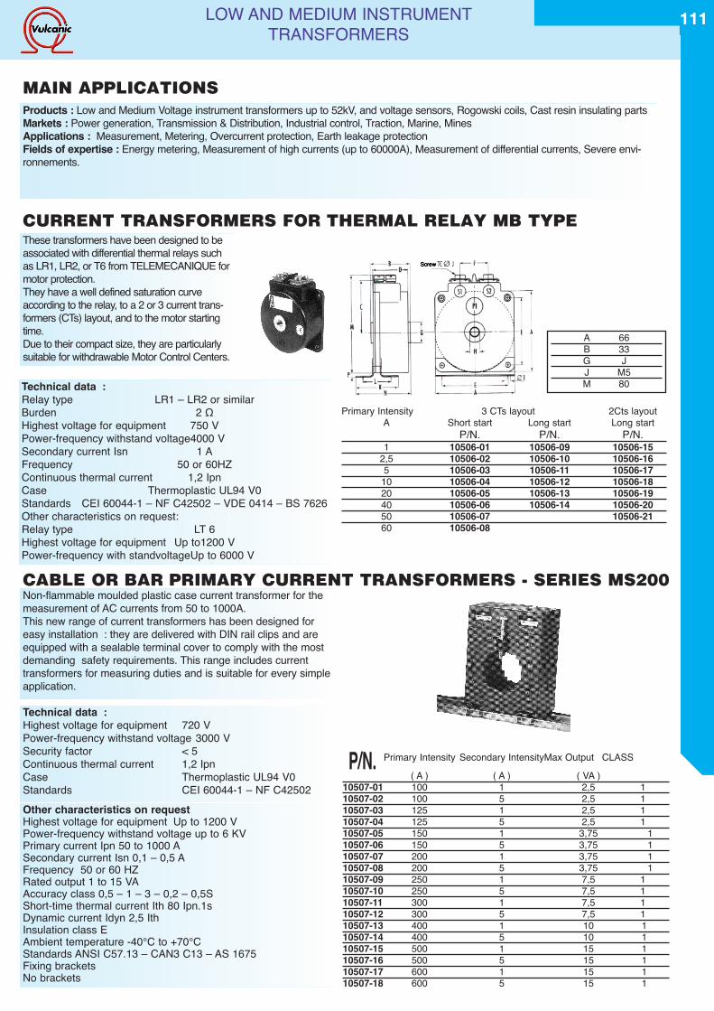
LOW AND MEDIUM INSTRUMENTTRANSFORMERS
MAIN APPLICATIONSProducts : Low and Medium Voltage instrument transformers up to 52kV, and voltage sensors, Rogowski coils, Cast resin insulating partsMarkets : Power generation, Transmission & Distribution, Industrial control, Traction, Marine, MinesApplications : Measurement, Metering, Overcurrent protection, Earth leakage protectionFields of expertise : Energy metering, Measurement of high currents (up to 60000A), Measurement of differential currents, Severe envi-ronnements.
Technical data :Relay type LR1 – LR2 or similarBurden 2 ΩHighest voltage for equipment 750 VPower-frequency withstand voltage4000 VSecondary current Isn 1 AFrequency 50 or 60HZContinuous thermal current 1,2 IpnCase Thermoplastic UL94 V0Standards CEI 60044-1 – NF C42502 – VDE 0414 – BS 7626Other characteristics on request:Relay type LT 6Highest voltage for equipment Up to1200 VPower-frequency with standvoltageUp to 6000 V
These transformers have been designed to beassociated with differential thermal relays suchas LR1, LR2, or T6 from TELEMECANIQUE formotor protection.They have a well defined saturation curveaccording to the relay, to a 2 or 3 current trans-formers (CTs) layout, and to the motor startingtime.Due to their compact size, they are particularlysuitable for withdrawable Motor Control Centers.
Primary Intensity 3 CTs layout 2Cts layoutA Short start Long start Long start
P/N. P/N. P/N.1 10506-01 10506-09 10506-15
2,5 10506-02 10506-10 10506-165 10506-03 10506-11 10506-1710 10506-04 10506-12 10506-1820 10506-05 10506-13 10506-1940 10506-06 10506-14 10506-2050 10506-07 10506-2160 10506-08
A 66B 33G JJ M5M 80
Non-flammable moulded plastic case current transformer for themeasurement of AC currents from 50 to 1000A.This new range of current transformers has been designed foreasy installation : they are delivered with DIN rail clips and areequipped with a sealable terminal cover to comply with the mostdemanding safety requirements. This range includes currenttransformers for measuring duties and is suitable for every simpleapplication.
P/N. Primary Intensity Secondary IntensityMax Output CLASS( A ) ( A ) ( VA )
10507-01 100 1 2,5 110507-02 100 5 2,5 110507-03 125 1 2,5 110507-04 125 5 2,5 110507-05 150 1 3,75 110507-06 150 5 3,75 110507-07 200 1 3,75 110507-08 200 5 3,75 110507-09 250 1 7,5 110507-10 250 5 7,5 110507-11 300 1 7,5 110507-12 300 5 7,5 110507-13 400 1 10 110507-14 400 5 10 110507-15 500 1 15 110507-16 500 5 15 110507-17 600 1 15 110507-18 600 5 15 1
Technical data :Highest voltage for equipment 720 VPower-frequency withstand voltage 3000 VSecurity factor < 5Continuous thermal current 1,2 IpnCase Thermoplastic UL94 V0Standards CEI 60044-1 – NF C42502Other characteristics on requestHighest voltage for equipment Up to 1200 VPower-frequency withstand voltage up to 6 KVPrimary current Ipn 50 to 1000 ASecondary current Isn 0,1 – 0,5 AFrequency 50 or 60 HZRated output 1 to 15 VAAccuracy class 0,5 – 1 – 3 – 0,2 – 0,5SShort-time thermal current Ith 80 Ipn.1sDynamic current Idyn 2,5 IthInsulation class EAmbient temperature -40°C to +70°CStandards ANSI C57.13 – CAN3 C13 – AS 1675Fixing bracketsNo brackets
CURRENT TRANSFORMERS FOR THERMAL RELAY MB TYPE
CABLE OR BAR PRIMARY CURRENT TRANSFORMERS - SERIES MS200
111
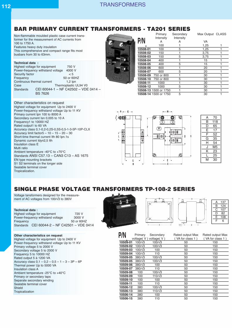
TRANSFORMERS
BAR PRIMARY CURRENT TRANSFORMERS - TA201 SERIESNon-flammable moulded plastic case current trans-former for the measurement of AC currents from100 to 1750 A.Features heavy duty insulationThis comprehensive and compact range fits mostbusbars from 30 to 63mm.
Primary Secondary Max Output CLASSIntensity Intensity
A A VA100 1 1,25 1
10508-01 100 5 1,25 110508-02 150 1 3,75 110508-03 150 5 3,75 110508-04 400 1 15 110508-05 400 5 15 110508-06 600 1 20 110508-07 600 5 20 110508-09 750 or 800 1 30 110508-10 750 or 800 5 30 110508-11 1000 1 30 110508-12 1000 5 30 110508-13 1500 or 1750 1 30 110508-14 1500 or 1750 5 30 1
Technical data :Highest voltage for equipment 750 VPower-frequency withstand voltage 4000 VSecurity factor < 5Frequency 50 or 60HZContinuous thermal current 1,2 IpnCase Thermoplastic UL94 V0Standards CEI 60044-1 – NF C42502 – VDE 0414 –
BS 7626
A 70B 118D 65E 17F 52G 35H 54J M5K 23L 25M 30
SINGLE PHASE VOLTAGE TRANSFORMERS TP-108-2 SERIESVoltage tansformers designed for the measure-ment of AC voltages from 100/√3 to 380V
Primary Secondary Rated output Max Rated output Maxvoltage( V ) voltage( V ) ( VA for class 1 ) ( VA for class 1 )
10509-01 100/√3 100/√3 50 15010509-02 100/√3 100/√3 50 15010509-03 100/√3 100 50 15010509-04 100/√3 110 50 15010509-05 380/√3 100/√3 50 15010509-05 380/√3 100/√3 50 15010509-06 380/√3 100 50 15010509-07 380/√3 110 50 15010509-08 100 100/√3 50 15010509-09 100 110/√3 50 15010509-10 100 100 50 15010509-11 100 110 50 15010506-12 380 100/√3 50 15010506-13 380 110/√3 50 15010506-14 380 100 50 15010506-15 380 110 50 150
Technical data :Highest voltage for equipment 720 VPower-frequency withstand voltage 3000 VFrequency 50 or 60HZStandards CEI 60044-2 – NF C42501 – VDE 0414
Other characteristics on requestHighest voltage for equipment Up to 2400 VPower-frequency withstand voltage Up to 11 KVPrimary voltage 5 to 2000 VSecondary voltage 5 to 2000 VFrequency 5 to 10000 HZRated output 5 à 1200 VAAccuracy class 0,1 – 0,2 – 0,5 – 1 – 3 – 3P – 6PThermal power Up to 5000 VAInsulation class AAmbient temperature -25°C to +40°CPrimary or secondary tapsSeparate secondary windingSealable terminal coverShieldTropicalization
Other characteristics on requestHighest voltage for equipment Up to 2400 VPower-frequency withstand voltage Up to 11 KVPrimary current Ipn 100 to 8000 ASecondary current Isn 0,005 to 10 AFrequency1 to 10000 HZRated output1 to 60 VAAccuracy class 0,1-0,2-0,2S-0,5S-0,5-1-3-5P-10P-CLXAccuracy limit factor5 – 10 – 15 – 20 – 30Short-time thermal current Ith 80 Ipn.1sDynamic current Idyn2,5 IthInsulation class EMulti ratioAmbient temperature -40°C to +70°CStandards ANSI C57.13 – CAN3 C13 – AS 1675EN type mounting bracketsS1 S2 terminals on the longer sideSealable terminal coverTropicalization.
A 137B 124C 107D 82E 108F 6
P/N.
P/N.
112
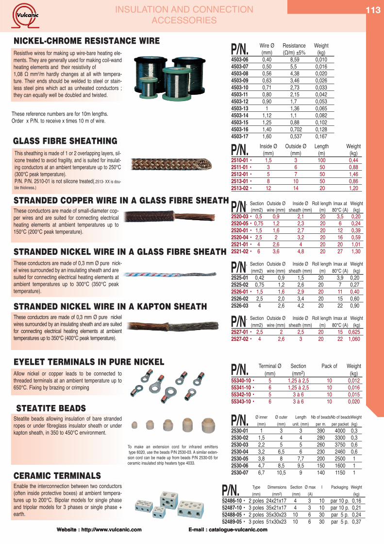
Website : http://www.vulcanic.com E-mail : catalogue-vulcanic.comWebsite : http://www.vulcanic.com E-mail : catalogue-vulcanic.com
Allow nickel or copper leads to be connected tothreaded terminals at an ambient temperature up to650°C. Fixing by brazing or crimping
P/N. Terminal Ø Section Pack of Weight(mm) (mm2) (kg)
55340-10 • 5 1,25 à 2,5 10 0,01255341-10 • 6 1,25 à 2,5 10 0,01655342-10 • 5 3 à 6 10 0,01555343-10 • 6 3 à 6 10 0,020
EYELET TERMINALS IN PURE NICKEL
These conductors are made of 0,3 mm Ø pure nickelwires surrounded by an insulating sheath and are suitedfor connecting electrical heating elements at ambienttemperatures up to 350°C (400°C peak temperature).
P/N. Section Outside Ø Inside Ø Roll length Imax at Weight(mm2) wire (mm) sheath (mm) (m) 80°C (A) (kg)
2527-01 • 2,5 2 2,5 20 15 0,6252527-02 • 4 2,6 3 20 22 1,060
STRANDED NICKEL WIRE IN A KAPTON SHEATH
This sheathing is made of 1 or 2 overlapping layers, sil-icone treated to avoid fragility, and is suited for insulat-ing conductors at an ambient temperature up to 250°C(300°C peak temperature).P/N. P/N. 2510-01 is not silicone treated(.2513- XX is dou-ble thickness.)
P/N. Inside Ø Outside Ø Length Weight(mm) (mm) (m) (kg)
2510-01 • 1,5 3 100 0,442511-01 • 3 6 50 0,882512-01 • 5 7 50 1,462513-01 • 8 10 50 0,862513-02 • 12 14 20 1,20
GLASS FIBRE SHEATHING
These conductors are made of small-diameter cop-per wires and are suited for connecting electricalheating elements at ambient temperatures up to150°C (200°C peak temperature).
P/N. Section Outside Ø Inside Ø Roll length Imax at Weight(mm2) wire (mm) sheath (mm) (m) 80°C (A) (kg)
2520-03 • 0,5 0,9 2,1 20 3,5 0,202520-05 • 0,75 1,2 2,3 20 6 0,242520-01 • 1,5 1,6 2,7 20 12 0,392520-04 • 2,5 2 3,2 20 16 0,592521-01 • 4 2,6 4 20 20 1,012521-02 • 6 3,6 4,8 20 27 1,30
These conductors are made of 0,3 mm Ø pure nick-el wires surrounded by an insulating sheath and aresuited for connecting electrical heating elements atambient temperatures up to 300°C (350°C peaktemperature).
P/N. Section Outside Ø Inside Ø Roll length Imax at Weight(mm2) wire (mm) sheath (mm) (m) 80°C (A) (kg)
2525-01 0,42 0,9 1,5 20 3,9 0,202525-02 0,75 1,2 2,6 20 7 0,272526-01 • 1,5 1,6 2,9 20 11 0,402526-02 2,5 2,0 3,4 20 15 0,602526-03 4 2,6 4,2 20 22 0,90
STRANDED COPPER WIRE IN A GLASS FIBRE SHEATH
STRANDED NICKEL WIRE IN A GLASS FIBRE SHEATH
ResistIve wires for making up wire-bare heating ele-ments. They are generally used for making coil-wandheating elements and their resistivity of 1,08 Ω mm2/m hardly changes at all with tempera-ture. Their ends should be welded to steel or stain-less steel pins which act as unheated conductors ;they can equally well be doubled and twisted.
P/N. Wire Ø Resistance Weight(mm) (Ω/m) ±5% (kg)
4503-06 0,40 8,59 0,0104503-07 0,50 5,5 0,0164503-08 0,56 4,38 0,0204503-09 0,63 3,46 0,0264503-10 0,71 2,73 0,0334503-11 0,80 2,15 0,0424503-12 0,90 1,7 0,0534503-13 1 1,36 0,0654503-14 1,12 1,1 0,0824503-15 1,25 0,88 0,1024503-16 1,40 0,702 0,1284503-17 1,60 0,537 0,167
These reference numbers are for 10m lengths.Order x P/N. to receive x times 10 m of wire.
NICKEL-CHROME RESISTANCE WIRE
Steatite beads allowing insulation of bare strandedropes or under fibreglass insulator sheath or underkapton sheath, in 350 to 450°C environment.
P/N. Ø inner Ø outer Length Nb of beadsNb of beadsWeight(mm) (mm) unit. (mm) per m. per packet (kg)
2530-01 1 3 3 390 4000 0,32530-02 1,5 4 4 280 3300 0,32530-03 2,2 5 5 260 3750 0,62530-04 3,2 6,5 6 230 2460 0,62530-05 3,8 8 7,7 200 2500 12530-06 4,7 8,5 9,5 150 1600 12530-07 6,7 10,5 9 140 1150 1
To make an extension cord for infrared emitters type 6020, use the beads P/N 2530-03. A similar exten-
sion cord can be made up from beads P/N 2530-05 forceramic insulated strip heaters type 4033.
Enable the interconnection between two conductors(often inside protective boxes) at ambient tempera-tures up to 200°C. Bipolar models for single phaseand tripolar models for 3 phases or single phase +earth.
P/N. Type Dimensions Section Ø max I Packaging Weight(mm) (mm2) (mm) (A) (kg)
52486-10 • 2 poles 24x21x17 4 3 10 par 10 p. 0,1652487-10 • 3 poles 35x21x17 4 3 10 par 10 p. 0,2152488-05 • 2 poles 35x30x23 10 6 30 par 5 p. 0,2452489-05 • 3 poles 51x30x23 10 6 30 par 5 p. 0,37
STEATITE BEADS
CERAMIC TERMINALS
Website : http://www.vulcanic.com E-mail : catalogue-vulcanic.com
INSULATION AND CONNECTION ACCESSORIES
113
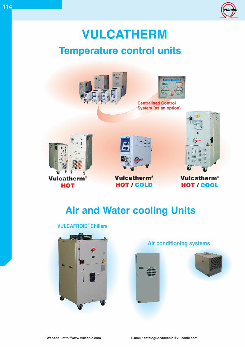
114
Website : http://www.vulcanic.com E-mail : [email protected]
VULCAFROID® Chillers
Vulcatherm®
HOTVulcatherm®
HOT / COLDVulcatherm®
HOT / COOL
Centralised ControlSystem (as an option)
Air and Water cooling Units
VULCATHERMTemperature control units
Air conditioning systems
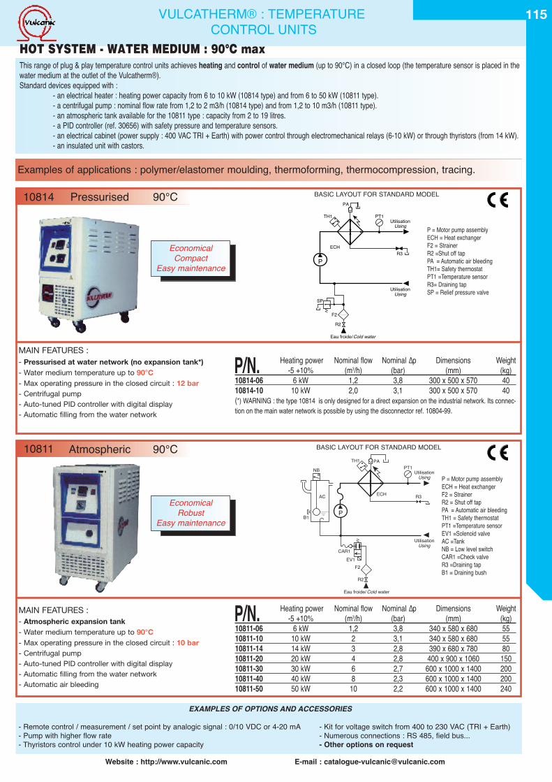
115
Website : http://www.vulcanic.com E-mail : [email protected]
MAIN FEATURES :- Pressurised at water network (no expansion tank*)- Water medium temperature up to 90°C- Max operating pressure in the closed circuit : 12 bar- Centrifugal pump- Auto-tuned PID controller with digital display- Automatic filling from the water network
P/N. Heating power Nominal flow Nominal ∆p Dimensions Weight-5 +10% (m3/h) (bar) (mm) (kg)
10814-06 6 kW 1,2 3,8 300 x 500 x 570 4010814-10 10 kW 2,0 3,1 300 x 500 x 570 40(*) WARNING : the type 10814 is only designed for a direct expansion on the industrial network. Its connec-tion on the main water network is possible by using the disconnector ref. 10804-99.
PT1
R3
F2
SP
R2
Eau froide/Cold water
ECH
P
Utilisation
UtilisationUsing
Using
TH1
PA
VVP = Motor pump assemblyECH = Heat exchangerF2 = StrainerR2 =Shut off tapPA = Automatic air bleedingTH1= Safety thermostatPT1 =Temperature sensorR3= Draining tapSP = Relief pressure valve
VULCATHERM® : TEMPERATURECONTROL UNITS
BASIC LAYOUT FOR STANDARD MODEL
EXAMPLES OF OPTIONS AND ACCESSORIES
- Remote control / measurement / set point by analogic signal : 0/10 VDC or 4-20 mA - Kit for voltage switch from 400 to 230 VAC (TRI + Earth)- Pump with higher flow rate - Numerous connections : RS 485, field bus...- Thyristors control under 10 kW heating power capacity - Other options on request
MAIN FEATURES :- Atmospheric expansion tank- Water medium temperature up to 90°C- Max operating pressure in the closed circuit : 10 bar- Centrifugal pump- Auto-tuned PID controller with digital display- Automatic filling from the water network- Automatic air bleeding
P/N. Heating power Nominal flow Nominal ∆p Dimensions Weight-5 +10% (m3/h) (bar) (mm) (kg)
10811-06 6 kW 1,2 3,8 340 x 580 x 680 5510811-10 10 kW 2 3,1 340 x 580 x 680 5510811-14 14 kW 3 2,8 390 x 680 x 780 8010811-20 20 kW 4 2,8 400 x 900 x 1060 15010811-30 30 kW 6 2,7 600 x 1000 x 1400 20010811-40 40 kW 8 2,3 600 x 1000 x 1400 20010811-50 50 kW 10 2,2 600 x 1000 x 1400 240
PT1
R3
CAR1
B1
F2
R2
Eau froide/ Cold water
ECH
P
UtilisationUsing
UtilisationUsing
TH1 PANB
AC
EV1
VV
P = Motor pump assemblyECH = Heat exchangerF2 = StrainerR2 = Shut off tapPA = Automatic air bleedingTH1 = Safety thermostatPT1 =Temperature sensorEV1 =Solenoid valveAC =TankNB = Low level switchCAR1 =Check valveR3 =Draining tapB1 = Draining bush
BASIC LAYOUT FOR STANDARD MODEL
Examples of applications : polymer/elastomer moulding, thermoforming, thermocompression, tracing.
10814 Pressurised 90°C
10811 Atmospheric 90°C
This range of plug & play temperature control units achieves heating and control of water medium (up to 90°C) in a closed loop (the temperature sensor is placed in thewater medium at the outlet of the Vulcatherm®).Standard devices equipped with :
- an electrical heater : heating power capacity from 6 to 10 kW (10814 type) and from 6 to 50 kW (10811 type).- a centrifugal pump : nominal flow rate from 1,2 to 2 m3/h (10814 type) and from 1,2 to 10 m3/h (10811 type).- an atmospheric tank available for the 10811 type : capacity from 2 to 19 litres.- a PID controller (ref. 30656) with safety pressure and temperature sensors.- an electrical cabinet (power supply : 400 VAC TRI + Earth) with power control through electromechanical relays (6-10 kW) or through thyristors (from 14 kW).- an insulated unit with castors.
HOT SYSTEM - WATER MEDIUM : 90°C max
EconomicalCompact
Easy maintenance
EconomicalRobust
Easy maintenance
115
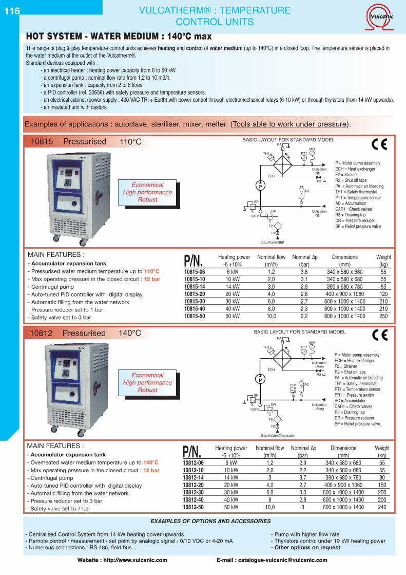
116
Website : http://www.vulcanic.com E-mail : [email protected] : http://www.vulcanic.com E-mail : [email protected]
MAIN FEATURES :- Accumulator expansion tank- Overheated water medium temperature up to 140°C- Max operating pressure in the closed circuit : 12 bar- Centrifugal pump- Auto-tuned PID controller with digital display- Automatic filling from the water network- Pressure reducer set to 3 bar- Safety valve set to 7 bar
MAIN FEATURES :- Accumulator expansion tank- Pressurised water medium temperature up to 110°C- Max operating pressure in the closed circuit : 12 bar- Centrifugal pump- Auto-tuned PID controller with digital display- Automatic filling from the water network- Pressure reducer set to 1 bar- Safety valve set to 3 bar
P/N. Heating power Nominal flow Nominal ∆p Dimensions Weight-5 +10% (m3/h) (bar) (mm) (kg)
10815-06 6 kW 1,2 3,8 340 x 580 x 680 5510815-10 10 kW 2,0 3,1 340 x 580 x 680 5510815-14 14 kW 3,0 2,8 390 x 680 x 780 8510815-20 20 kW 4,0 2,8 400 x 900 x 1060 12010815-30 30 kW 6,0 2,7 600 x 1000 x 1400 21010815-40 40 kW 8,0 2,3 600 x 1000 x 1400 21010815-50 50 kW 10,0 2,2 600 x 1000 x 1400 250
P/N. Heating power Nominal flow Nominal ∆p Dimensions Weight-5 +10% (m3/h) (bar) (mm) (kg)
10812-06 6 kW 1,2 2,9 340 x 580 x 680 5510812-10 10 kW 2,0 2,2 340 x 580 x 680 5510812-14 14 kW 3 3,7 390 x 680 x 780 8010812-20 20 kW 4,0 2,7 400 x 900 x 1060 15010812-30 30 kW 6,0 3,3 600 x 1000 x 1400 20010812-40 40 kW 8 2,8 600 x 1000 x 1400 20010812-50 50 kW 10,0 3 600 x 1000 x 1400 240
PR1 AC
PT1MN
R3
CAR1
F2
DR
SP
R2
Eau froide/Cold water
ECH
P
Utilisation
UtilisationUsing
Using
TH1
PA
VV
VV
3 b
P = Motor pump assemblyECH = Heat exchangerF2 = StrainerR2 = Shut off tapsPA = Automatic air bleedingTH1 = Safety thermostatPT1 = Temperature sensorPR1 = Pressure switchAC = AccumulatorCAR1 = Check valvesR3 = Draining tapDR = Pressure reducerSP = Relief pressure valve
AC
PT1MN
R3
CAR1
F2
DR
SP
R2
Eau froide/Coldwater
ECH
P
Utilisation
UtilisationUsing
Using
TH1
PA
VV
VV
1 b
P = Motor pump assemblyECH = Heat exchangerF2 = StrainerR2 = Shut off tapsPA = Automatic air bleedingTH1 = Safety thermostatPT1 = Temperature sensorAC = AccumulatorCAR1 =Check valvesR3 = Draining tapDR = Pressure reducerSP = Relief pressure valve
VULCATHERM® : TEMPERATURECONTROL UNITS
This range of plug & play temperature control units achieves heating and control of water medium (up to 140°C) in a closed loop. The temperature sensor is placed inthe water medium at the outlet of the Vulcatherm®.Standard devices equipped with :
- an electrical heater : heating power capacity from 6 to 50 kW.- a centrifugal pump : nominal flow rate from 1,2 to 10 m3/h.- an expansion tank : capacity from 2 to 8 litres.- a PID controller (ref. 30656) with safety pressure and temperature sensors.- an electrical cabinet (power supply : 400 VAC TRI + Earth) with power control through electromechanical relays (6-10 kW) or through thyristors (from 14 kW upwards).- an insulated unit with castors.
BASIC LAYOUT FOR STANDARD MODEL
Examples of applications : autoclave, steriliser, mixer, melter. (Tools able to work under pressure).
BASIC LAYOUT FOR STANDARD MODEL
EXAMPLES OF OPTIONS AND ACCESSORIES
- Centralised Control System from 14 kW heating power upwards - Pump with higher flow rate- Remote control / measurement / set point by analogic signal : 0/10 VDC or 4-20 mA - Thyristors control under 10 kW heating power- Numerous connections : RS 485, field bus... - Other options on request
10815 Pressurised 110°C
10812 Pressurised 140°C
HOT SYSTEM - WATER MEDIUM : 140°C max
EconomicalHigh performance
Robust
EconomicalHigh performance
Robust
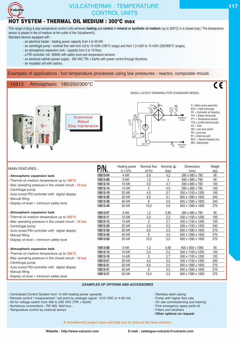
MAIN FEATURES :
- Atmospheric expansion tank- Thermal oil medium temperature up to 180°C- Max operating pressure in the closed circuit : 10 bar- Centrifugal pump- Auto-tuned PID controller with digital display- Manual filling- Display oil level + minimum safety level
- Atmospheric expansion tank- Thermal oil medium temperature up to 250°C- Max operating pressure in the closed circuit : 10 bar- Centrifugal pump- Auto-tuned PID controller with digital display- Manual filling- Display oil level + minimum safety level
- Atmospheric expansion tank- Thermal oil medium temperature up to 300°C- Max operating pressure in the closed circuit : 10 bar- Centrifugal pump- Auto-tuned PID controller with digital display- Manual filling- Display oil level + minimum safety level
117
Website : http://www.vulcanic.com E-mail : [email protected]
P/N. Heating power Nominal flow Nominal ∆p Dimensions Weight-5 +10% (m3/h) (bar) (mm) (kg)
10813-04 4 kW 0,8 4,2 390 x 680 x 780 9010813-06 6 kW 1,2 3 390 x 680 x 780 9010813-10 10 kW 2,0 4,7 390 x 680 x 780 10010813-14 14 kW 3 4,5 390 x 680 x 780 10010813-19 20 kW 4,0 2,7 500 x 1100 x 1200 16010813-29 30 kW 6,0 3,1 600 x 1280 x 1600 24010813-39 40 kW 8 3,9 600 x 1280 x 1600 24010813-49 50 kW 10,0 3,8 600 x 1280 x 1600 27010813-07 6 kW 1,2 0,85 390 x 680 x 780 9010813-11 10 kW 2,0 2,2 500 x 1100 x 1200 10010813-15 14 kW 3 2,7 500 x 1100 x 1200 10010813-20 20 kW 4,0 3,2 500 x 1100 x 1200 24010813-30 30 kW 6,0 2,5 600 x 1280 x 1600 27010813-40 40 kW 8 3,5 600 x 1280 x 1600 27010813-50 50 kW 10,0 3,5 600 x 1280 x 1600 270
10813-08 6 kW 1,2 0,85 400 x 900 x 1060 9010813-12 10 kW 2,0 2,2 500 x 1100 x 1200 10010813-16 14 kW 3 2,7 500 x 1100 x 1200 10010813-21 20 kW 4,0 3,2 500 x 1100 x 1200 24010813-31 30 kW 6,0 2,5 600 x 1280 x 1600 27010813-41 40 kW 8 3,5 600 x 1280 x 1600 27010813-51 50 kW 10,0 3,5 600 x 1280 x 1600 270
PT1MN
B1
ECH
P
UtilisationUsing
UtilisationUsing
TH1TC2
PA
NB
AC
BCV
R5
P = Motor pump assemblyECH = Heat exchangerPA = Automatic air bleedingTH1 = Safety thermostatPT1 = Temperature sensorTC2 = Limiter thermocoupleAC = TankNB = Low level switchR5 = Level tapB1 = Draining bushBCV = Speed breaking boxMN = Manometer
This range of plug & play temperature control units achieves heating and control of mineral or synthetic oil medium (up to 300°C) in a closed loop.( The temperaturesensor is placed in the oil medium at the outlet of the Vulcatherm®).Standard devices equipped with :
- an electrical heater : heating power capacity from 4 to 50 kW.- an centrifugal pump : nominal flow rate from 0,8 to 10 m3/h (180°C range) and from 1,2 m3/h to 10 m3/h (250/300°C ranges).- an atmospheric expansion tank : capacity from 2 to 19 litres.- a PID controller (ref. 30656) with safety level and temperature sensors.- an electrical cabinet (power supply : 400 VAC TRI + Earth) with power control through thyristors.- an insulated unit with castors.
VULCATHERM® : TEMPERATURECONTROL UNITS
BASIC LAYOUT DRAWING FOR STANDARD MODEL
Examples of applications : hot temperature processes using low pressures : reactor, composite mould.
EXAMPLES OF OPTIONS AND ACCESSORIES
- Centralised Control System from 14 kW heating power upwards - Stenless steel casing- Remote control / measurement / set point by analogic signal : 0/10 VDC or 4-20 mA - Pump with higher flow rate- Kit for voltage switch from 400 to 230 VAC (TRI + Earth) - On site commissioning and training- Numerous connections : RS 485, field bus... - First emergency spare parts kit- Temperature control by external sensor - Filters and strainers
- Other options on request
A Vulcatherm® project team will help you to find out the best solution.
10813 Atmospheric 180/250/300°C
HOT SYSTEM - THERMAL OIL MEDIUM : 300°C max
EconomicalRobust
Easy maintenance
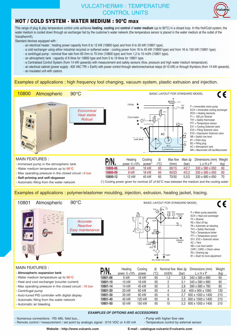
118 VULCATHERM® : TEMPERATURECONTROL UNITS
This range of plug & play temperature control units achieves heating, cooling and control of water medium (up to 90°C) in a closed loop. In this Hot/Cold system, thewater medium is cooled down through an exchanger fed by the customerʼs water network (the temperature sensor is placed in the water medium at the outlet of theVulcatherm®).Standard devices equipped with :
- an electrical heater : heating power capacity from 6 to 12 kW (10800 type) and from 6 to 50 kW (10801 type).- a cold exchanger using either industrial recycled or softened water : cooling power from 16 to 45 kW (10800 type) and from 16 to 150 kW (10801 type).- a centrifugal pump : nominal flow rate from 60 l/mn to 70 l/mn (10800 type) and from 1,2 to 10 m3/h (10801 type).- an atmospheric tank : capacity of 8 litres for 10800 type and from 5 to 19 litres for 10801 type.- a Centralised Control System (from 14 kW upwards) with measurement and safety sensors (flow, pressure and high water medium temperature).- an electrical cabinet (power supply : 400 VAC TRI + Earth) with power control through electromechanical relays (6-10 kW) or through thyristors (from 14 kW upwards).- an insulated unit with castors.
Examples of applications : high frequency tool changing, vacuum system, plastic extrusion and injection.
HOT / COLD SYSTEM - WATER MEDIUM : 90°C max
Low level
B2
AC
Using
Cool water
P/N. Heating Cooling ∆t Max flow Maxi ∆p Dimensions (mm) Weightpower -5 +10% power* (°C) (l/mn) (bar) L x H x P (kg)
10800-06 6 kW 16 kW 65 60/15 4/2,7 330 x 580 x 650 6010800-09 9 kW 18 kW 65 60/23 4/2,2 330 x 580 x 650 6010800-12 12 kW 45 kW 65 70/30 5,5/3 330 x 680 x 650 70
P = Immersible motor pumpECH = Immersible cooling exchangerRCH = Heating elementsF1 = 500 µm StrainerTH1 = Safety thermostatPT1 = Temperature sensorEV1 = Cooling Solenoid valveEV2 = Filling Solenoid valveEV3 = Depression Solenoid valveNB = Switch low levelB1 = Drain plugB2 = Filling plugAC = Atmospheric tankMN = Manometer 0/6 bar/Manometer
MAIN FEATURES :- Immersed pump in the atmospheric tank- Water medium temperature up to 90°C- Max operating pressure in the closed circuit : 8 bar- Self-priming and self-degasser- Automatic filling from the water network (*) Cooling power given for nominal ∆T of 65°C max between the medium and the cooling water
BASIC LAYOUT FOR STANDARD MODEL10800 Atmospheric 90°C
EconomicalHeat stable
Robust
MAIN FEATURES :- Atmospheric expansion tank- Water medium temperature up to 90°C- Heat and cool exchanger (counter current)- Max operating pressure in the closed circuit : 10 bar- Centrifugal pump- Auto-tuned PID controller with digital display- Automatic filling from the water network- Automatic air bleeding
TH2 PT1
R3
CAR1
CAR2
B1
F2
R2
Eau froide/ Cool water
EV1
ECH
P
UtilisationUsing
UtilisationUsing
TH1 PANB
AC
VV
EV2
VV
P = Motor pump assemblyECH = Heat cool exchangerF2 = StrainerR2 = Shut off tapPA = Automatic air bleedingTH1 = Safety thermostatTH2 = Temperature limiterPT1 = Temperature sensorEV1, EV2 = Solenoid valvesAC = TankNB = Low level switchCAR1, CAR2 = Check valvesR3 = Draining tapB1 = Bush for level adjustment
P/N. Heating Cooling ∆t Nominal flow Maxi ∆p Dimensions (mm) Weightpower -5 +10% power (°C) (m3/h) (bar) L x H x P (kg)
10801-06 6 kW 16 kW 65 1,2 3,8 340 x 580 x 680 6010801-10 10 kW 18 kW 65 2 3,1 340 x 580 x 680 6010801-14 14 kW 45 kW 65 3 2,8 390 x 680 x 780 8510801-20 20 kW 60 kW 65 4 2,8 400 x 900 x 1060 12010801-30 30 kW 90 kW 65 6 2,7 600 x 1000 x 1400 21010801-40 40 kW 120 kW 65 8 2,3 600 x 1000 x 1400 21010801-50 50 kW 150 kW 65 10 2,2 600 x 1000 x 1400 210
Examples of applications : polymer/elastomer moulding, injection, extrusion, heating jacket, tracing.
BASIC LAYOUT FOR STANDARD MODEL10801 Atmospheric 90°C
AccurateReactive
Easy maintenance
Website : http://www.vulcanic.com E-mail : [email protected]
EXAMPLES OF OPTIONS AND ACCESSORIES- Numerous connections : RS 485, field bus... - Pump with higher flow rate- Remote control / measurement / set point by analogic signal : 0/10 VDC or 4-20 mA - Temperature control by external sensor
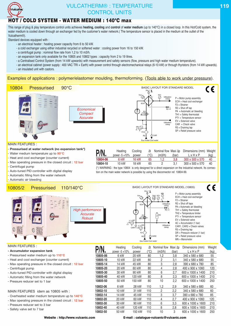
MAIN FEATURES idem as 10805 with :- Overheated water medium temperature up to 140°C- Max operating pressure in the closed circuit : 12 bar- Pressure reducer set to 3 bar- Safety valve set to 7 bar
119
Website : http://www.vulcanic.com E-mail : [email protected] : http://www.vulcanic.com E-mail : [email protected]
10802-06 6 kW 28 kW 110 1,2 2,9 340 x 580 x 680 6010802-10 10 kW 31 kW 110 2 2,2 340 x 580 x 680 6010802-14 14 kW 45 kW 110 3 3,7 390 x 680 x 780 8510802-20 20 kW 60 kW 110 4 2,7 400 x 900 x 1060 12010802-30 30 kW 90 kW 110 6 3,3 600 x 1000 x 1600 21010802-40 40 kW 120 kW 110 8 2,8 600 x 1000 x 1600 21010802-50 50 kW 150 kW 110 10 3 600 x 1000 x 1600 250
AC
PT1MN
R3
CAR1
CAR2F2
DR
SP
R2
Eau froide/Cool water
EV
ECH
P
Utilisation
UtilisationUsing
Using
TH1 TH2
PA
VV
VV
VV
1 b
P = Motor pump assemblyECH = Heat cool exchangerF2 = StrainerR2 = Shut off tapsPA = Automatic air bleedingTH1 = Safety thermostatTH2 = Temperature limiterPT1 = Temperature sensorEV = Solenoid valveAC = Accumulator (1 bar)CAR1, CAR2 = Check valvesR3 = Draining tapDR = Pressure reducer (1 bar)SP = Relief pressure valveMN = Manometer
P = Motor pump assemblyECH = Heat cool exchangerF2 = StrainerR2 = Shut off tapPA = Automatic air bleedingTH1 = Safety thermostatPT1 = Temperature sensorEV = Solenoid valveCAR = Check valveR3 = Draining tapSP = Relief pressure valve
VULCATHERM® : TEMPERATURECONTROL UNITS
MAIN FEATURES :- Accumulator expansion tank- Pressurised water medium up to 110°C- Heat and cool exchanger (counter current)- Max operating pressure in the closed circuit : 12 bar- Centrifugal pump- Auto-tuned PID controller with digital display- Automatic filling from the water network- Pressure reducer set to 1 bar
P/N. Heating Cooling ∆t Nominal flow Maxi ∆p Dimensions (mm) Weightpower -5 +10% power (°C) (m3/h) (bar) L x H x P (kg)
10805-06 6 kW 20 kW 80 1,2 3,8 340 x 580 x 680 5510805-10 10 kW 22 kW 80 2 3,1 340 x 580 x 680 5510805-14 14 kW 45 kW 80 3 2,8 390 x 680 x 780 8510805-20 20 kW 60 kW 80 4 2,8 400 x 900 x 1060 12010805-30 30 kW 90 kW 80 6 2,7 600 x 1000 x 1400 21010805-40 40 kW 120 kW 80 8 2,3 600 x 1000 x 1400 21010805-50 50 kW 150 kW 80 10 2,2 600 x 1000 x 1400 250
This range of plug & play temperature control units achieves heating, cooling and control of water medium (up to 140°C) in a closed loop. In this Hot/Cold system, thewater medium is cooled down through an exchanger fed by the customerʼs water network.( The temperature sensor is placed in the medium at the outlet of theVulcatherm®).Standard devices equipped with :
- an electrical heater : heating power capacity from 6 to 50 kW.- a cold exchanger using either industrial recycled or softened water : cooling power from 16 to 150 kW.- a centrifugal pump : nominal flow rate from 1,2 to 10 m3/h.- an expansion tank only available for the 10805 and 10802 types : capacity from 2 to 19 litres.- a Centralised Control System (from 14 kW upwards) with measurement and safety sensors (flow, pressure and high water medium temperature).- an electrical cabinet (power supply : 400 VAC TRI + Earth) with power control through electromechanical relays (6-10 kW) or through thyristors (from 14 kW upwards).- an insulated unit with castors.
Examples of applications : polymer/elastomer moulding, thermoforming. (Tools able to work under pressure).
PT1
R3
CARF2
SP
R2
Eau froide/Cool water
EV
ECH
P
Utilisation
UtilisationUsing
Using
TH1
PA
VV
VV
P/N. Heating Cooling ∆t Nominal flow Maxi ∆p Dimensions (mm) Weightpower -5 +10% power (°C) (m3/h) (bar) L x H x P (kg)
10804-06 6 kW 16 kW 65 1,2 3,8 300 x 500 x 570 4010804-10 10 kW 18 kW 65 2 3,1 300 x 500 x 570 40(*) WARNING : the type 10804 is only designed for a direct expansion on the industrial network. Its connec-tion on the main water network is possible by using the disconnector ref. 10804-99.
10804
BASIC LAYOUT FOR STANDARD MODEL (10805)
Pressurised 90°C
10805/2 Pressurised 110/140°C
BASIC LAYOUT FOR STANDARD MODEL
MAIN FEATURES :- Pressurised at water network (no expansion tank*)- Water medium temperature up to 90°C- Heat and cool exchanger (counter current)- Max operating pressure in the closed circuit : 12 bar- Centrifugal pump- Auto-tuned PID controller with digital display- Automatic filling from the water network- Automatic air bleeding
HOT / COLD SYSTEM - WATER MEDIUM : 140°C max
High performanceAccurateRobust
EconomicalCompactAccurate
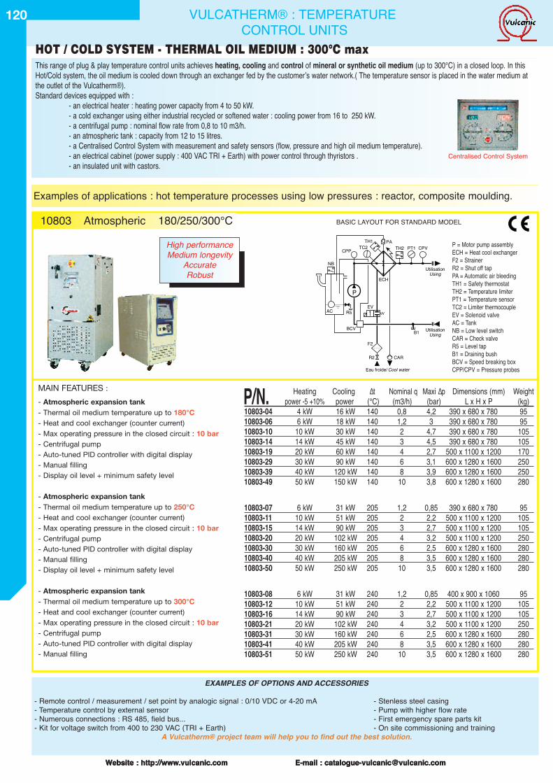
120
Website : http://www.vulcanic.com E-mail : [email protected] : http://www.vulcanic.com E-mail : [email protected] : http://www.vulcanic.com E-mail : [email protected]
This range of plug & play temperature control units achieves heating, cooling and control of mineral or synthetic oil medium (up to 300°C) in a closed loop. In thisHot/Cold system, the oil medium is cooled down through an exchanger fed by the customerʼs water network.( The temperature sensor is placed in the water medium atthe outlet of the Vulcatherm®).Standard devices equipped with :
- an electrical heater : heating power capacity from 4 to 50 kW.- a cold exchanger using either industrial recycled or softened water : cooling power from 16 to 250 kW.- a centrifugal pump : nominal flow rate from 0,8 to 10 m3/h.- an atmospheric tank : capacity from 12 to 15 litres.- a Centralised Control System with measurement and safety sensors (flow, pressure and high oil medium temperature).- an electrical cabinet (power supply : 400 VAC TRI + Earth) with power control through thyristors .- an insulated unit with castors.
TH2 PT1 CPVCPP
CAR
B1
F2
R2
Eau froide/ Cool water
EV
ECH
P
UtilisationUsing
UtilisationUsing
TH1TC2
PA
NB
AC
BCV
R5 VV
P = Motor pump assemblyECH = Heat cool exchangerF2 = StrainerR2 = Shut off tapPA = Automatic air bleedingTH1 = Safety thermostatTH2 = Temperature limiterPT1 = Temperature sensorTC2 = Limiter thermocoupleEV = Solenoid valveAC = TankNB = Low level switchCAR = Check valveR5 = Level tapB1 = Draining bushBCV = Speed breaking boxCPP/CPV = Pressure probes
P/N. Heating Cooling ∆t Nominal q Maxi ∆p Dimensions (mm) Weightpower -5 +10% power (°C) (m3/h) (bar) L x H x P (kg)
10803-04 4 kW 16 kW 140 0,8 4,2 390 x 680 x 780 9510803-06 6 kW 18 kW 140 1,2 3 390 x 680 x 780 9510803-10 10 kW 30 kW 140 2 4,7 390 x 680 x 780 10510803-14 14 kW 45 kW 140 3 4,5 390 x 680 x 780 10510803-19 20 kW 60 kW 140 4 2,7 500 x 1100 x 1200 17010803-29 30 kW 90 kW 140 6 3,1 600 x 1280 x 1600 25010803-39 40 kW 120 kW 140 8 3,9 600 x 1280 x 1600 25010803-49 50 kW 150 kW 140 10 3,8 600 x 1280 x 1600 280
10803-07 6 kW 31 kW 205 1,2 0,85 390 x 680 x 780 9510803-11 10 kW 51 kW 205 2 2,2 500 x 1100 x 1200 10510803-15 14 kW 90 kW 205 3 2,7 500 x 1100 x 1200 10510803-20 20 kW 102 kW 205 4 3,2 500 x 1100 x 1200 25010803-30 30 kW 160 kW 205 6 2,5 600 x 1280 x 1600 28010803-40 40 kW 205 kW 205 8 3,5 600 x 1280 x 1600 28010803-50 50 kW 250 kW 205 10 3,5 600 x 1280 x 1600 280
10803-08 6 kW 31 kW 240 1,2 0,85 400 x 900 x 1060 9510803-12 10 kW 51 kW 240 2 2,2 500 x 1100 x 1200 10510803-16 14 kW 90 kW 240 3 2,7 500 x 1100 x 1200 10510803-21 20 kW 102 kW 240 4 3,2 500 x 1100 x 1200 25010803-31 30 kW 160 kW 240 6 2,5 600 x 1280 x 1600 28010803-41 40 kW 205 kW 240 8 3,5 600 x 1280 x 1600 28010803-51 50 kW 250 kW 240 10 3,5 600 x 1280 x 1600 280
VULCATHERM® : TEMPERATURECONTROL UNITS
MAIN FEATURES :
- Atmospheric expansion tank- Thermal oil medium temperature up to 180°C- Heat and cool exchanger (counter current)- Max operating pressure in the closed circuit : 10 bar- Centrifugal pump- Auto-tuned PID controller with digital display- Manual filling- Display oil level + minimum safety level
- Atmospheric expansion tank- Thermal oil medium temperature up to 250°C- Heat and cool exchanger (counter current)- Max operating pressure in the closed circuit : 10 bar- Centrifugal pump- Auto-tuned PID controller with digital display- Manual filling- Display oil level + minimum safety level
- Atmospheric expansion tank- Thermal oil medium temperature up to 300°C- Heat and cool exchanger (counter current)- Max operating pressure in the closed circuit : 10 bar- Centrifugal pump- Auto-tuned PID controller with digital display- Manual filling
Examples of applications : hot temperature processes using low pressures : reactor, composite moulding.
BASIC LAYOUT FOR STANDARD MODEL
EXAMPLES OF OPTIONS AND ACCESSORIES
- Remote control / measurement / set point by analogic signal : 0/10 VDC or 4-20 mA - Stenless steel casing- Temperature control by external sensor - Pump with higher flow rate- Numerous connections : RS 485, field bus... - First emergency spare parts kit- Kit for voltage switch from 400 to 230 VAC (TRI + Earth) - On site commissioning and training
A Vulcatherm® project team will help you to find out the best solution.
Centralised Control System
10803 Atmospheric 180/250/300°C
HOT / COLD SYSTEM - THERMAL OIL MEDIUM : 300°C max
High performanceMedium longevity
AccurateRobust
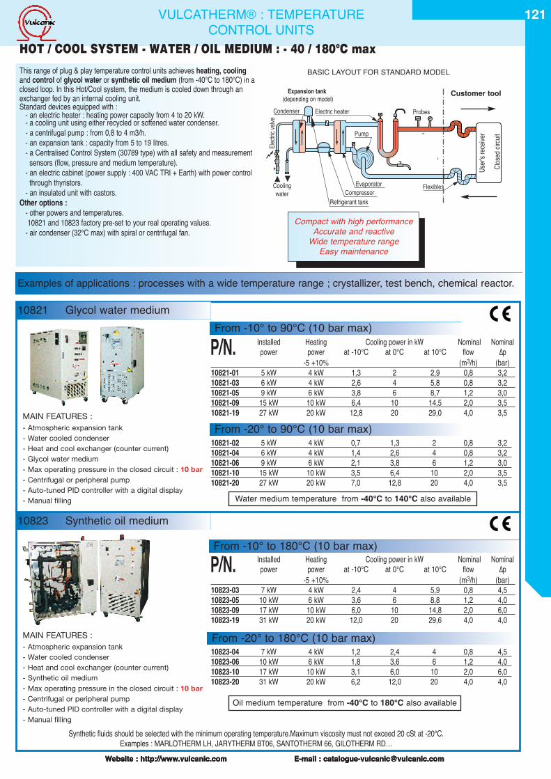
10821 Glycol water medium
121
Website : http://www.vulcanic.com E-mail : [email protected] : http://www.vulcanic.com E-mail : [email protected] : http://www.vulcanic.com E-mail : [email protected] : http://www.vulcanic.com E-mail : [email protected]
Pump
Electric heater
Evaporator
R�servoirfr�on R22
Compressor
Condenser
Cooling�water
Electr
ic va
lve
User'
s rec
eiver
Probes
Flexibles
Clos
ed ci
rcuit
Refrigerant tank
BASIC LAYOUT FOR STANDARD MODEL
Synthetic fluids should be selected with the minimum operating temperature.Maximum viscosity must not exceed 20 cSt at -20°C.Examples : MARLOTHERM LH, JARYTHERM BT06, SANTOTHERM 66, GILOTHERM RD…
Expansion tank(depending on model)
Water medium temperature from -40°C to 140°C also available
Oil medium temperature from -40°C to 180°C also available
VULCATHERM® : TEMPERATURECONTROL UNITS
This range of plug & play temperature control units achieves heating, coolingand control of glycol water or synthetic oil medium (from -40°C to 180°C) in aclosed loop. In this Hot/Cool system, the medium is cooled down through anexchanger fed by an internal cooling unit.Standard devices equipped with :
- an electric heater : heating power capacity from 4 to 20 kW.- a cooling unit using either recycled or softened water condenser.- a centrifugal pump : from 0,8 to 4 m3/h.- an expansion tank : capacity from 5 to 19 litres.- a Centralised Control System (30789 type) with all safety and measurement
sensors (flow, pressure and medium temperature).- an electric cabinet (power supply : 400 VAC TRI + Earth) with power control
through thyristors.- an insulated unit with castors.
Other options :- other powers and temperatures.10821 and 10823 factory pre-set to your real operating values.
- air condenser (32°C max) with spiral or centrifugal fan.
P/N. Installed Heating Cooling power in kW Nominal Nominalpower power at -10°C at 0°C at 10°C flow ∆p
-5 +10% (m3/h) (bar)10821-01 5 kW 4 kW 1,3 2 2,9 0,8 3,210821-03 6 kW 4 kW 2,6 4 5,8 0,8 3,210821-05 9 kW 6 kW 3,8 6 8,7 1,2 3,010821-09 15 kW 10 kW 6,4 10 14,5 2,0 3,510821-19 27 kW 20 kW 12,8 20 29,0 4,0 3,5
P/N. Installed Heating Cooling power in kW Nominal Nominalpower power at -10°C at 0°C at 10°C flow ∆p
-5 +10% (m3/h) (bar)10823-03 7 kW 4 kW 2,4 4 5,9 0,8 4,510823-05 10 kW 6 kW 3,6 6 8,8 1,2 4,010823-09 17 kW 10 kW 6,0 10 14,8 2,0 6,010823-19 31 kW 20 kW 12,0 20 29,6 4,0 4,0
Examples of applications : processes with a wide temperature range ; crystallizer, test bench, chemical reactor.
Customer tool
From -20° to 90°C (10 bar max)
10823 Synthetic oil medium
HOT / COOL SYSTEM - WATER / OIL MEDIUM : - 40 / 180°C max
10821-02 5 kW 4 kW 0,7 1,3 2 0,8 3,210821-04 6 kW 4 kW 1,4 2,6 4 0,8 3,210821-06 9 kW 6 kW 2,1 3,8 6 1,2 3,010821-10 15 kW 10 kW 3,5 6,4 10 2,0 3,510821-20 27 kW 20 kW 7,0 12,8 20 4,0 3,5
10823-04 7 kW 4 kW 1,2 2,4 4 0,8 4,510823-06 10 kW 6 kW 1,8 3,6 6 1,2 4,010823-10 17 kW 10 kW 3,1 6,0 10 2,0 6,010823-20 31 kW 20 kW 6,2 12,0 20 4,0 4,0
Compact with high performanceAccurate and reactive
Wide temperature rangeEasy maintenance
MAIN FEATURES :- Atmospheric expansion tank- Water cooled condenser- Heat and cool exchanger (counter current)- Glycol water medium- Max operating pressure in the closed circuit : 10 bar- Centrifugal or peripheral pump- Auto-tuned PID controller with a digital display- Manual filling
From -20° to 180°C (10 bar max)MAIN FEATURES :- Atmospheric expansion tank- Water cooled condenser- Heat and cool exchanger (counter current)- Synthetic oil medium- Max operating pressure in the closed circuit : 10 bar- Centrifugal or peripheral pump- Auto-tuned PID controller with a digital display- Manual filling
From -10° to 90°C (10 bar max)
From -10° to 180°C (10 bar max)
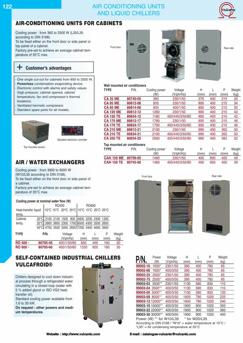
122
Website : http://www.vulcanic.com E-mail : [email protected] : http://www.vulcanic.com E-mail : [email protected] : http://www.vulcanic.com E-mail : [email protected]
TYPE P/N. Voltage H L P Weight(V/ph/Hz) (mm) (mm) (mm) (kg)
RO 400 • 80705-40 400/1/50/60 850 400 160 20RO 600 • 80705-60 400/1/50/60 1250 600 160 30
P/N. Power Voltage H L P Weight(W) (V/ph/Hz) (mm) (mm) (mm) (kg)
99002-16 1600* 230/1/50 395 400 780 6599002-66 1600* 400/3/50 395 400 780 6599002-25 2500* 230/1/50 395 400 780 6599002-75 2500* 400/3/50 395 400 780 6599003-03 3500** 230/1/50 1130 580 830 11099003-04 3500** 400/3/50 1130 580 830 11099003-05 5000** 400/3/50 1130 580 830 12099003-08 8000** 400/3/50 1600 780 1020 22599003-12 12000** 400/3/50 1600 780 1020 24099003-16 16000** 400/3/50 1900 900 1020 35099003-22 22000** 400/3/50 1900 900 1020 36099003-30 30000** 400/3/50 1900 900 1020 400Power (W) ** for W10/L35 * for W20/L35According to DIN 3168 / “W10” = water temperature at 10°C /“L35” = Air condensing temperature at 35°C
Cooling power : from 360 to 2500 W (L35/L35according to DIN 3168).To be fixed either on the front door or side panel ortop panel of a cabinet.Factory pre-set to achieve an average cabinet tem-perature of 35°C max.
Wall mounted air conditionersTYPE P/N. Cooling power Voltage H L P Weight
(W) (V/ph/Hz) (mm) (mm) (mm) (kg)CA 35 ME 80740-00 360 230/1/50 376 400 215 20CA 85 ME 80812-08 850 230/1/50 800 400 215 34CA 85 ME 80814-08 850 400/1/50 800 400 215 35CA 120 ME 80812-12 1260 230/1/50 900 400 215 42CA 120 TE 80834-12 1180 400/440/3/50/60 900 400 215 42CA 170 ME 80812-17 1760 230/1/50 950 400 215 46CA 170 TE 80834-17 1700 400/440/3/50/60 950 400 215 46CA 210 ME 80812-21 2100 230/1/50 990 400 262 50CA 210 TE 80834-21 2100 400/440/3/50/60 990 400 262 50CA 250 TE 80834-25 2500 400/440/3/50/60 990 400 262 52Top mounted air conditionersTYPE P/N. Cooling power Voltage H L P Weight
(W) (V/ph/Hz) (mm) (mm) (mm) (kg)CAH 150 ME 80799-00 1460 230/1/50 400 600 400 49CAH 150 TE 80745-00 1460 400/440/3/50/60 400 600 400 39
Cooling power : from 3900 to 6000 W(W10/L35 according to DIN 3168).To be fixed either on the front door or side panel ofa cabinet.Factory pre-set to achieve an average cabinet tem-perature of 35°C max.
Chillers designed to cool down industri-al process through a refrigerated watercirculating in a closed loop (water with5 % added glycol or ISO VG2 heat-transfer oil).Standard cooling power available from1,6 to 30 kW.On request : other powers and medi-um temperatures.
Cooling power at nominal water flow (W)RO400 RO600
Heat-transfer liquid 10°C 15°C 20°C 25°C 10°C 15°C 20°C 25°Ctemp.Cabinet 30°C 3100 2100 1500 800 4800 3200 2300 1300temp. 35°C 3900 3800 2300 1700 6000 4300 3500 2600
40°C 4700 3500 3000 2600 7200 5400 4600 3900
SELF-CONTAINED INDUSTRIAL CHILLERSVULCAFROID®
Front face
Standard electronic controller
Top mounted version
Rear side
Front face Rear side
AIR / WATER EXCHANGERS
AIR-CONDITIONING UNITS FOR CABINETS
+ Customer’s advantages
- One single cut-out for cabinets from 850 to 2500 W.- Powerless condensation evaporating device.- Electronic control with alarms and safety values
(high pressure, cabinet opened, cabinettemperature, fan and compressorʼs thermalbreakers).
- Ventilated hermetic compressor.- Standard spare parts for all models.
Website : http://www.vulcanic.com E-mail : [email protected] : http://www.vulcanic.com E-mail : [email protected]
AIR CONDITIONING UNITSAND LIQUID CHILLERS
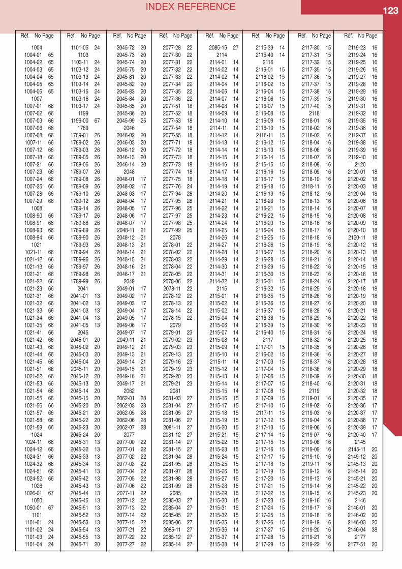
123INDEX REFERENCE
10041004-01 651004-02 651004-03 651004-04 651004-05 651004-06 65
10071007-01 661007-02 661007-03 661007-06 661007-08 661007-11 661007-12 661007-18 661007-21 661007-23 661007-24 661007-25 661007-28 661007-29 66
10081008-90 661008-91 661008-93 661008-94 66
10211021-11 661021-12 661021-13 661021-21 661021-22 661021-23 661021-31 661021-32 661021-33 661021-34 661021-35 661021-41 661021-42 661021-43 661021-44 661021-45 661021-51 661021-52 661021-53 661021-54 661021-55 661021-56 661021-57 661021-58 661021-59 66
10241024-11 661024-12 661024-31 661024-32 661024-51 661024-52 66
10261026-01 67
10501050-01 67
11011101-01 241101-02 241101-03 241101-04 24
1101-05 241103
1103-11 241103-12 241103-13 241103-14 241103-15 241103-16 241103-17 24
11991199-00 67
17891789-01 261789-02 261789-03 261789-05 261789-06 261789-07 261789-08 261789-09 261789-10 261789-12 261789-14 261789-17 261789-88 261789-89 261789-90 261789-93 261789-94 261789-96 261789-97 261789-98 261789-99 26
20412041-01 132041-02 132041-03 132041-04 132041-05 13
20452045-01 202045-02 202045-03 202045-04 202045-11 202045-12 202045-13 202045-14 202045-15 202045-20 202045-21 202045-22 202045-23 202045-24 202045-31 132045-32 132045-33 132045-34 132045-41 132045-42 132045-43 132045-44 132045-45 132045-51 132045-52 132045-53 132045-54 132045-55 132045-71 20
2045-72 202045-73 202045-74 202045-75 202045-81 202045-82 202045-83 202045-84 202045-85 202045-86 202045-99 25
20462046-02 202046-03 202046-12 202046-13 202046-14 20
20482048-01 172048-02 172048-03 172048-04 172048-05 172048-06 172048-07 172048-11 212048-12 212048-13 212048-14 212048-15 212048-16 212048-17 21
20492049-01 172049-02 172049-03 172049-04 172049-05 172049-06 172049-07 172049-11 212049-12 212049-13 212049-14 212049-15 212049-16 212049-17 21
20622062-01 282062-03 282062-05 282062-06 282062-07 28
20772077-00 222077-01 222077-02 222077-03 222077-04 222077-05 222077-06 222077-11 222077-12 222077-13 222077-14 222077-15 222077-21 222077-22 222077-27 22
2077-28 222077-30 222077-31 222077-32 222077-33 222077-34 222077-35 222077-36 222077-51 182077-52 182077-53 182077-54 182077-55 182077-71 182077-72 182077-73 182077-73 182077-74 182077-75 182077-76 242077-94 282077-95 282077-96 252077-97 252077-98 252077-99 25
20782078-01 222078-02 222078-03 222078-04 222078-05 222078-06 222078-11 222078-12 222078-13 222078-14 222078-15 22
20792079-01 232079-02 232079-03 232079-13 232079-16 232079-19 232079-20 232079-21 23
20812081-03 272081-04 272081-05 272081-06 272081-11 272081-12 272081-14 272081-15 272081-94 282081-95 282081-97 282081-98 282081-99 28
20852085-03 272085-04 272085-05 272085-06 272085-11 272085-12 272085-14 27
2085-15 272114
2114-01 142114-02 142114-02 142114-04 142114-06 142114-07 142114-08 142114-09 142114-10 142114-11 142114-12 142114-13 142114-14 142114-15 142114-16 142114-17 142114-18 142114-19 142114-20 142114-21 142114-22 142114-23 142114-24 142114-25 142114-26 142114-27 142114-28 142114-29 142114-30 142114-31 142114-32 14
21152115-01 142115-02 142115-02 142115-04 142115-06 142115-07 142115-08 142115-09 142115-10 142115-11 142115-12 142115-13 142115-14 142115-15 142115-16 152115-17 152115-18 152115-19 152115-20 152115-21 152115-22 152115-23 152115-24 152115-25 152115-26 152115-27 152115-28 152115-29 152115-30 152115-31 152115-32 152115-35 142115-36 142115-37 142115-38 14
2115-39 142115-40 14
21162116-01 152116-02 152116-02 152116-04 152116-06 152116-07 152116-08 152116-09 152116-10 152116-11 152116-12 152116-13 152116-14 152116-15 152116-16 152116-17 152116-18 152116-19 152116-20 152116-21 152116-22 152116-23 152116-24 152116-25 152116-26 152116-27 152116-28 152116-29 152116-30 152116-31 152116-32 152116-35 152116-36 152116-37 152116-38 152116-39 152116-40 15
21172117-01 152116-02 152117-03 152117-04 152117-06 152117-07 152117-08 152117-09 152117-10 152117-11 152117-12 152117-13 152117-14 152117-15 152117-16 152117-17 152117-18 152117-19 152117-20 152117-21 152117-22 152117-23 152117-24 152117-25 152117-26 152117-27 152117-28 152117-29 15
2117-30 152117-31 152117-32 152117-35 152117-36 152117-37 152117-38 152117-39 152117-40 15
21182118-01 162118-02 162118-02 162118-04 162118-06 162118-07 162118-08 162118-09 162118-10 162118-11 162118-12 162118-13 162118-14 162118-15 162118-16 162118-17 162118-18 162118-19 162118-20 162118-21 162118-22 162118-23 162118-24 162118-25 162118-26 162118-27 162118-28 162118-29 162118-30 162118-31 162118-32 162118-35 162118-36 162118-37 162118-38 162118-39 162118-40 16
21192119-01 162119-02 162119-03 162119-04 162119-06 162119-07 162119-08 162119-09 162119-10 162119-11 162119-12 162119-13 162119-14 162119-15 162119-16 162119-17 162119-18 162119-19 162119-20 162119-21 162119-22 16
2119-23 162119-24 162119-25 162119-26 162119-27 162119-28 162119-29 162119-30 162119-31 162119-32 162119-35 162119-36 162119-37 162119-38 162119-39 162119-40 16
21202120-01 182120-02 182120-03 182120-04 182120-06 182120-07 182120-08 182120-09 182120-10 182120-11 182120-12 182120-13 182120-14 182120-15 182120-16 182120-17 182120-18 182120-19 182120-20 182120-21 182120-22 182120-23 182120-24 182120-25 182120-26 182120-27 182120-28 182120-29 182120-30 182120-31 182120-32 182120-35 172120-36 172120-37 172120-38 172120-39 172120-40 17
21452145-11 202145-12 202145-13 202145-14 202145-21 202145-22 202145-23 20
21462146-01 202146-02 202146-03 202146-04 38
21772177-51 20
Réf. No Page Réf. No Page Réf. No Page Réf. No Page Réf. No Page Réf. No Page Réf. No Page Réf. No Page
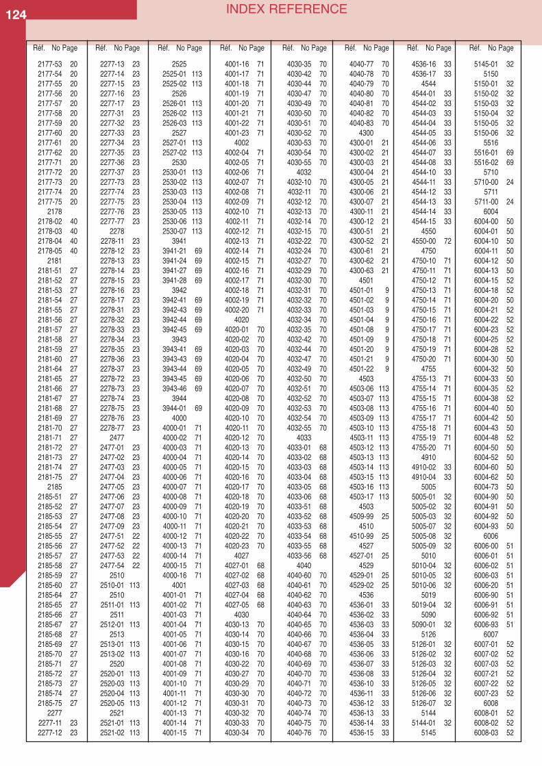
124 INDEX REFERENCE
2177-53 202177-54 202177-55 202177-56 202177-57 202177-58 202177-59 202177-60 202177-61 202177-62 202177-71 202177-72 202177-73 202177-74 202177-75 20
21782178-02 402178-03 402178-04 402178-05 40
21812181-51 272181-52 272181-53 272181-54 272181-55 272181-56 272181-57 272181-58 272181-59 272181-60 272181-64 272181-65 272181-66 272181-67 272181-68 272181-69 272181-70 272181-71 272181-72 272181-73 272181-74 272181-75 27
21852185-51 272185-52 272185-53 272185-54 272185-55 272185-56 272185-57 272185-58 272185-59 272185-60 272185-64 272185-65 272185-66 272185-67 272185-68 272185-69 272185-70 272185-71 272185-72 272185-73 272185-74 272185-75 27
22772277-11 232277-12 23
2277-13 232277-14 232277-15 232277-16 232277-17 232277-31 232277-32 232277-33 232277-34 232277-35 232277-36 232277-37 232277-73 232277-74 232277-75 232277-76 232277-77 23
22782278-11 232278-12 232278-13 232278-14 232278-15 232278-16 232278-17 232278-31 232278-32 232278-33 232278-34 232278-35 232278-36 232278-37 232278-72 232278-73 232278-74 232278-75 232278-76 232278-77 23
24772477-01 232477-02 232477-03 232477-04 232477-05 232477-06 232477-07 232477-08 232477-09 232477-51 222477-52 222477-53 222477-54 22
25102510-01 113
25102511-01 113
25112512-01 113
25132513-01 1132513-02 113
25202520-01 1132520-03 1132520-04 1132520-05 113
25212521-01 1132521-02 113
25252525-01 1132525-02 113
25262526-01 1132526-02 1132526-03 113
25272527-01 1132527-02 113
25302530-01 1132530-02 1132530-03 1132530-04 1132530-05 1132530-06 1132530-07 113
39413941-21 693941-24 693941-27 693941-28 69
39423942-41 693942-43 693942-44 693942-45 69
39433943-41 693943-43 693943-44 693943-45 693943-46 69
39443944-01 69
40004000-01 714000-02 714000-03 714000-04 714000-05 714000-06 714000-07 714000-08 714000-09 714000-10 714000-11 714000-12 714000-13 714000-14 714000-15 714000-16 71
40014001-01 714001-02 714001-03 714001-04 714001-05 714001-06 714001-07 714001-08 714001-09 714001-10 714001-11 714001-12 714001-13 714001-14 714001-15 71
4001-16 714001-17 714001-18 714001-19 714001-20 714001-21 714001-22 714001-23 71
40024002-04 714002-05 714002-06 714002-07 714002-08 714002-09 714002-10 714002-11 714002-12 714002-13 714002-14 714002-15 714002-16 714002-17 714002-18 714002-19 714002-20 71
40204020-01 704020-02 704020-03 704020-04 704020-05 704020-06 704020-07 704020-08 704020-09 704020-10 704020-11 704020-12 704020-13 704020-14 704020-15 704020-16 704020-17 704020-18 704020-19 704020-20 704020-21 704020-22 704020-23 70
40274027-01 684027-02 684027-03 684027-04 684027-05 68
40304030-13 704030-14 704030-15 704030-16 704030-22 704030-27 704030-29 704030-30 704030-31 704030-32 704030-33 704030-34 70
4030-35 704030-42 704030-44 704030-47 704030-49 704030-50 704030-51 704030-52 704030-53 704030-54 704030-55 70
40324032-10 704032-11 704032-12 704032-13 704032-14 704032-15 704032-22 704032-24 704032-27 704032-29 704032-30 704032-31 704032-32 704032-33 704032-34 704032-35 704032-42 704032-44 704032-47 704032-49 704032-50 704032-51 704032-52 704032-53 704032-54 704032-55 70
40334033-01 684033-02 684033-03 684033-04 684033-05 684033-06 684033-51 684033-52 684033-53 684033-54 684033-55 684033-56 68
40404040-60 704040-61 704040-62 704040-63 704040-64 704040-65 704040-66 704040-67 704040-68 704040-69 704040-70 704040-71 704040-72 704040-73 704040-74 704040-75 704040-76 70
4040-77 704040-78 704040-79 704040-80 704040-81 704040-82 704040-83 70
43004300-01 214300-02 214300-03 214300-04 214300-05 214300-06 214300-07 214300-11 214300-12 214300-51 214300-52 214300-61 214300-62 214300-63 21
45014501-01 94501-02 94501-03 94501-04 94501-08 94501-09 94501-20 94501-21 94501-22 9
45034503-06 1134503-07 1134503-08 1134503-09 1134503-10 1134503-11 1134503-12 1134503-13 1134503-14 1134503-15 1134503-16 1134503-17 113
45034509-99 25
45104510-99 25
45274527-01 25
45294529-01 254529-02 25
45364536-01 334536-02 334536-03 334536-04 334536-05 334536-06 334536-07 334536-08 334536-10 334536-11 334536-12 334536-13 334536-14 334536-15 33
4536-16 334536-17 33
45444544-01 334544-02 334544-03 334544-04 334544-05 334544-06 334544-07 334544-08 334544-10 334544-11 334544-12 334544-13 334544-14 334544-15 33
45504550-00 72
47504750-10 714750-11 714750-12 714750-13 714750-14 714750-15 714750-16 714750-17 714750-18 714750-19 714750-20 71
47554755-13 714755-14 714755-15 714755-16 714755-17 714755-18 714755-19 714755-20 71
49104910-02 334910-04 33
50055005-01 325005-02 325005-03 325005-07 325005-08 325005-09 32
50105010-04 325010-05 325010-06 32
50195019-04 32
50905090-01 32
51265126-01 325126-02 325126-03 325126-04 325126-05 325126-06 325126-07 32
51445144-01 32
5145
5145-01 325150
5150-01 325150-02 325150-03 325150-04 325150-05 325150-06 32
55165516-01 695516-02 69
57105710-00 24
57115711-00 24
60046004-00 506004-01 506004-10 506004-11 506004-12 506004-13 506004-15 526004-18 526004-20 506004-21 526004-22 526004-23 526004-25 526004-28 526004-30 506004-32 506004-33 506004-35 526004-38 526004-40 506004-42 506004-43 506004-48 526004-50 506004-52 506004-60 506004-62 506004-73 506004-90 506004-91 506004-92 506004-93 50
60066006-00 516006-01 516006-02 516006-03 516006-20 516006-90 516006-91 516006-92 516006-93 51
60076007-01 526007-02 526007-03 526007-21 526007-22 526007-23 52
60086008-01 526008-02 526008-03 52
Réf. No Page Réf. No Page Réf. No Page Réf. No Page Réf. No Page Réf. No Page Réf. No Page Réf. No Page
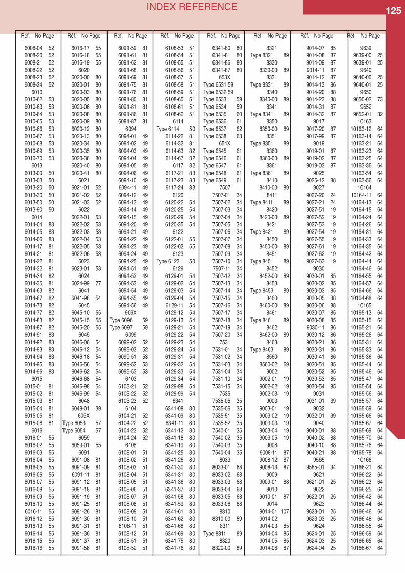
125INDEX REFERENCE
6008-04 526008-20 526008-21 526008-22 526008-23 526008-24 52
60106010-62 536010-63 536010-64 536010-65 536010-66 536010-67 536010-68 536010-69 536010-70 53
60136013-00 506013-03 506013-20 506013-30 506013-50 506013-90 50
60146014-04 836014-05 836014-06 836014-17 816014-21 816014-22 816014-32 816014-34 826014-35 816014-63 826014-67 826014-73 826014-77 826014-83 826014-87 826014-91 836014-92 836014-93 836014-94 836014-95 836014-96 83
60156015-01 816015-02 816015-03 816015-04 816015-05 816015-06 81
60166016-01 556016-02 556016-03 556016-04 556016-05 556016-06 556016-07 556016-08 556016-09 556016-10 556016-11 556016-12 556016-13 556016-14 556016-15 556016-16 55
6016-17 556016-18 556016-19 55
60206020-00 806020-01 806020-03 806020-05 806020-06 806020-08 806020-09 806020-12 806020-13 806020-34 806020-35 806020-36 806020-40 806020-41 80
60216021-01 526021-02 526021-03 52
60226022-01 536022-02 536022-03 536022-04 536022-05 536022-06 53
60236023-01 53
60246024-99 77
60416041-98 54
60456045-10 556045-15 556045-20 55
60456046-06 546046-12 546046-18 546046-56 546046-62 546046-68 546046-98 546046-99 54
60486048-01 39
605XType 6053 57Type 6054 57
60596059-01 55
60916091-08 816091-09 816091-11 816091-12 816091-18 816091-19 816091-25 816091-26 816091-30 816091-31 816091-36 816091-37 816091-58 81
6091-59 816091-61 816091-62 816091-68 816091-69 816091-75 816091-76 816091-80 816091-81 816091-86 816091-87 81
60946094-01 496094-02 496094-03 496094-04 496094-05 496094-06 496094-10 496094-11 496094-12 496094-13 496094-14 496094-15 496094-20 496094-21 496094-22 496094-23 496094-24 496094-25 496094-51 496094-52 496094-53 496094-54 496094-55 496094-56 49
609XType 6096 59Type 6097 59
60996099-02 526099-03 526099-51 536099-52 536099-53 53
61036103-21 526103-22 526103-23 52
61046104-21 526104-22 526104-23 526104-24 52
61086108-01 516108-02 516108-03 516108-04 516108-05 516108-06 516108-07 516108-08 516108-09 516108-10 516108-11 516108-12 516108-51 516108-52 51
6108-53 516108-54 516108-55 516108-56 516108-57 516108-58 516108-59 516108-60 516108-61 516108-62 51
6114Type 6114 50
6114-22 816114-32 816114-63 826114-67 82
6117 826117-21 836117-23 836117-24 83
61206120-22 546120-25 546120-29 546120-35 54
61226122-01 556122-02 55
6123Type 6123 50
61296129-01 546129-02 546129-03 546129-04 546129-11 546129-12 546129-13 546129-21 546129-22 546129-23 546129-24 546129-31 546129-32 546129-33 546129-34 546129-98 546129-99 54
63416341-08 806341-09 806341-11 806341-12 806341-18 806341-19 806341-25 806341-26 806341-30 806341-31 806341-36 806341-37 806341-58 806341-59 806341-61 806341-62 806341-68 806341-69 806341-75 806341-76 80
6341-80 806341-81 806341-86 806341-87 80
653XType 6531 59Type 6532 59Type 6533 59Type 6534 59Type 6535 60Type 6536 61Type 6537 62Type 6538 63
654XType 6545 61Type 6546 61Type 6547 61Type 6548 61Type 6549 61
75077507-01 347507-02 347507-03 347507-04 347507-05 347507-06 347507-07 347507-08 347507-09 347507-10 347507-11 347507-12 347507-13 347507-14 347507-15 347507-16 347507-17 347507-18 347507-19 347507-20 34
75317531-01 347531-02 347531-03 347531-04 347531-10 347531-15 34
75357535-05 357535-06 357535-51 357535-52 357540-01 357540-02 357540-03 357540-04 35
80338033-01 688033-02 688033-03 688033-04 688033-05 688033-06 68
83108310-00 89
8311Type 8311 89
83208320-00 89
8321Type 8321 89
83308330-00 89
8331Type 8331 89
83408340-00 89
8341Type 8341 89
83508350-00 89
8351Type 8351 89
83608360-00 89
8361Type 8361 89
84108410-00 89
8411Type 8411 89
84208420-00 89
8421Type 8421 89
84508450-00 89
8451Type 8451 89
84528452-00 89
8453Type 8453 89
84608460-00 89
8461Type 8461 89
84628462-00 89
8463Type 8463 89
85608560-02 69
90029002-01 199002-02 199002-03 19
90039003-01 199003-02 199003-03 199003-04 199003-05 19
90089008-11 879008-12 879008-13 87
90099009-01 88
90109010-01 87
90149014-01 1079014-029014-03 859014-04 859014-05 859014-06 87
9014-07 859014-08 879014-09 879014-11 879014-12 879014-13 869014-20 889014-23 889014-31 879014-32 87
90179017-20 879017-99 87
90199019-01 879019-02 879019-03 87
90259025-12 88
90279027-20 249027-21 249027-51 199027-52 199027-53 199027-54 199027-55 199027-61 199027-62 199027-63 19
90309030-01 859030-02 859030-03 859030-05 889030-06 889030-07 859030-08 859030-11 869030-12 869030-21 869030-31 869030-41 869030-51 859030-52 859030-53 859030-54 85
90319031-01 39
90329032-01 39
90409040-01 889040-02 889040-10 889040-21 88
95659565-01 34
96219621-01 25
96229622-01 25
96239623-01 259623-03 25
96249624-01 259624-03 259624-04 25
96399639-00 259639-01 25
96409640-00 259640-01 25
96509650-02 73
96529652-01 32
1016310163-12 6410163-14 6410163-21 6410163-23 6410163-25 6410163-36 6410163-54 6410163-56 64
1016410164-11 6410164-13 6410164-15 6410164-24 6410164-26 6410164-31 6410164-33 6410164-35 6410164-42 6410164-44 6410164-46 6410164-55 6410164-57 6410164-66 6410164-68 64
1016510165-13 6410165-15 6410165-21 6410165-26 6410165-31 6410165-33 6410165-36 6410165-44 6410165-46 6410165-47 6410165-54 6410165-56 6410165-57 6410165-59 6410165-66 6410165-67 6410165-69 6410165-70 6410165-76 6410165-78 64
1016610166-21 6410166-22 6410166-23 6410166-25 6410166-42 6410166-44 6410166-46 6410166-48 6410166-55 6410166-59 6410166-65 6410166-67 64
Réf. No Page Réf. No Page Réf. No Page Réf. No Page Réf. No Page Réf. No Page Réf. No Page Réf. No Page
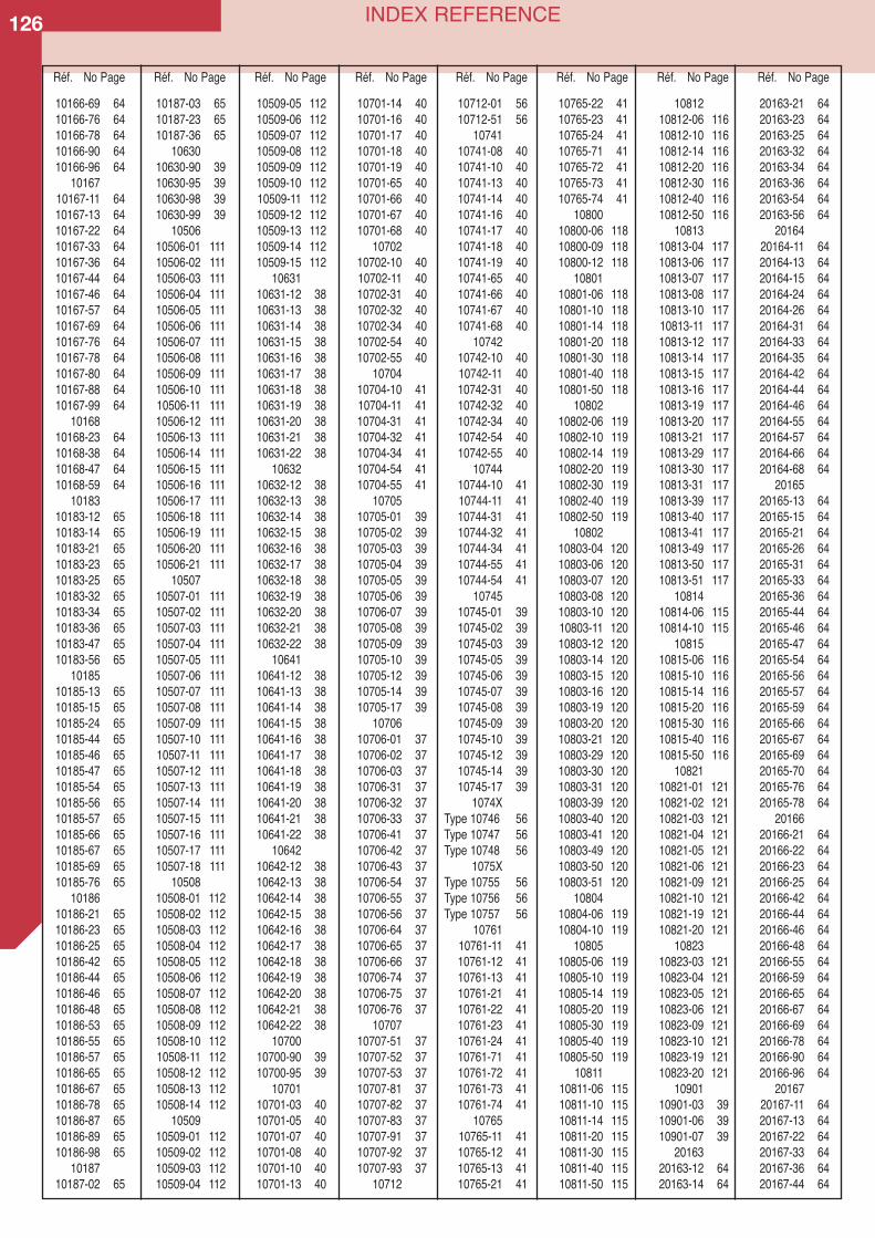
126 INDEX REFERENCE
10166-69 6410166-76 6410166-78 6410166-90 6410166-96 64
1016710167-11 6410167-13 6410167-22 6410167-33 6410167-36 6410167-44 6410167-46 6410167-57 6410167-69 6410167-76 6410167-78 6410167-80 6410167-88 6410167-99 64
1016810168-23 6410168-38 6410168-47 6410168-59 64
1018310183-12 6510183-14 6510183-21 6510183-23 6510183-25 6510183-32 6510183-34 6510183-36 6510183-47 6510183-56 65
1018510185-13 6510185-15 6510185-24 6510185-44 6510185-46 6510185-47 6510185-54 6510185-56 6510185-57 6510185-66 6510185-67 6510185-69 6510185-76 65
1018610186-21 6510186-23 6510186-25 6510186-42 6510186-44 6510186-46 6510186-48 6510186-53 6510186-55 6510186-57 6510186-65 6510186-67 6510186-78 6510186-87 6510186-89 6510186-98 65
1018710187-02 65
10187-03 6510187-23 6510187-36 65
1063010630-90 3910630-95 3910630-98 3910630-99 39
1050610506-01 11110506-02 11110506-03 11110506-04 11110506-05 11110506-06 11110506-07 11110506-08 11110506-09 11110506-10 11110506-11 11110506-12 11110506-13 11110506-14 11110506-15 11110506-16 11110506-17 11110506-18 11110506-19 11110506-20 11110506-21 111
1050710507-01 11110507-02 11110507-03 11110507-04 11110507-05 11110507-06 11110507-07 11110507-08 11110507-09 11110507-10 11110507-11 11110507-12 11110507-13 11110507-14 11110507-15 11110507-16 11110507-17 11110507-18 111
1050810508-01 11210508-02 11210508-03 11210508-04 11210508-05 11210508-06 11210508-07 11210508-08 11210508-09 11210508-10 11210508-11 11210508-12 11210508-13 11210508-14 112
1050910509-01 11210509-02 11210509-03 11210509-04 112
10509-05 11210509-06 11210509-07 11210509-08 11210509-09 11210509-10 11210509-11 11210509-12 11210509-13 11210509-14 11210509-15 112
1063110631-12 3810631-13 3810631-14 3810631-15 3810631-16 3810631-17 3810631-18 3810631-19 3810631-20 3810631-21 3810631-22 38
1063210632-12 3810632-13 3810632-14 3810632-15 3810632-16 3810632-17 3810632-18 3810632-19 3810632-20 3810632-21 3810632-22 38
1064110641-12 3810641-13 3810641-14 3810641-15 3810641-16 3810641-17 3810641-18 3810641-19 3810641-20 3810641-21 3810641-22 38
1064210642-12 3810642-13 3810642-14 3810642-15 3810642-16 3810642-17 3810642-18 3810642-19 3810642-20 3810642-21 3810642-22 38
1070010700-90 3910700-95 39
1070110701-03 4010701-05 4010701-07 4010701-08 4010701-10 4010701-13 40
10701-14 4010701-16 4010701-17 4010701-18 4010701-19 4010701-65 4010701-66 4010701-67 4010701-68 40
1070210702-10 4010702-11 4010702-31 4010702-32 4010702-34 4010702-54 4010702-55 40
1070410704-10 4110704-11 4110704-31 4110704-32 4110704-34 4110704-54 4110704-55 41
1070510705-01 3910705-02 3910705-03 3910705-04 3910705-05 3910705-06 3910706-07 3910705-08 3910705-09 3910705-10 3910705-12 3910705-14 3910705-17 39
1070610706-01 3710706-02 3710706-03 3710706-31 3710706-32 3710706-33 3710706-41 3710706-42 3710706-43 3710706-54 3710706-55 3710706-56 3710706-64 3710706-65 3710706-66 3710706-74 3710706-75 3710706-76 37
1070710707-51 3710707-52 3710707-53 3710707-81 3710707-82 3710707-83 3710707-91 3710707-92 3710707-93 37
10712
10712-01 5610712-51 56
1074110741-08 4010741-10 4010741-13 4010741-14 4010741-16 4010741-17 4010741-18 4010741-19 4010741-65 4010741-66 4010741-67 4010741-68 40
1074210742-10 4010742-11 4010742-31 4010742-32 4010742-34 4010742-54 4010742-55 40
1074410744-10 4110744-11 4110744-31 4110744-32 4110744-34 4110744-55 4110744-54 41
1074510745-01 3910745-02 3910745-03 3910745-05 3910745-06 3910745-07 3910745-08 3910745-09 3910745-10 3910745-12 3910745-14 3910745-17 39
1074XType 10746 56Type 10747 56Type 10748 56
1075XType 10755 56Type 10756 56Type 10757 56
1076110761-11 4110761-12 4110761-13 4110761-21 4110761-22 4110761-23 4110761-24 4110761-71 4110761-72 4110761-73 4110761-74 41
1076510765-11 4110765-12 4110765-13 4110765-21 41
10765-22 4110765-23 4110765-24 4110765-71 4110765-72 4110765-73 4110765-74 41
1080010800-06 11810800-09 11810800-12 118
1080110801-06 11810801-10 11810801-14 11810801-20 11810801-30 11810801-40 11810801-50 118
1080210802-06 11910802-10 11910802-14 11910802-20 11910802-30 11910802-40 11910802-50 119
1080210803-04 12010803-06 12010803-07 12010803-08 12010803-10 12010803-11 12010803-12 12010803-14 12010803-15 12010803-16 12010803-19 12010803-20 12010803-21 12010803-29 12010803-30 12010803-31 12010803-39 12010803-40 12010803-41 12010803-49 12010803-50 12010803-51 120
1080410804-06 11910804-10 119
1080510805-06 11910805-10 11910805-14 11910805-20 11910805-30 11910805-40 11910805-50 119
1081110811-06 11510811-10 11510811-14 11510811-20 11510811-30 11510811-40 11510811-50 115
1081210812-06 11610812-10 11610812-14 11610812-20 11610812-30 11610812-40 11610812-50 116
1081310813-04 11710813-06 11710813-07 11710813-08 11710813-10 11710813-11 11710813-12 11710813-14 11710813-15 11710813-16 11710813-19 11710813-20 11710813-21 11710813-29 11710813-30 11710813-31 11710813-39 11710813-40 11710813-41 11710813-49 11710813-50 11710813-51 117
1081410814-06 11510814-10 115
1081510815-06 11610815-10 11610815-14 11610815-20 11610815-30 11610815-40 11610815-50 116
1082110821-01 12110821-02 12110821-03 12110821-04 12110821-05 12110821-06 12110821-09 12110821-10 12110821-19 12110821-20 121
1082310823-03 12110823-04 12110823-05 12110823-06 12110823-09 12110823-10 12110823-19 12110823-20 121
1090110901-03 3910901-06 3910901-07 39
2016320163-12 6420163-14 64
20163-21 6420163-23 6420163-25 6420163-32 6420163-34 6420163-36 6420163-54 6420163-56 64
2016420164-11 6420164-13 6420164-15 6420164-24 6420164-26 6420164-31 6420164-33 6420164-35 6420164-42 6420164-44 6420164-46 6420164-55 6420164-57 6420164-66 6420164-68 64
2016520165-13 6420165-15 6420165-21 6420165-26 6420165-31 6420165-33 6420165-36 6420165-44 6420165-46 6420165-47 6420165-54 6420165-56 6420165-57 6420165-59 6420165-66 6420165-67 6420165-69 6420165-70 6420165-76 6420165-78 64
2016620166-21 6420166-22 6420166-23 6420166-25 6420166-42 6420166-44 6420166-46 6420166-48 6420166-55 6420166-59 6420166-65 6420166-67 6420166-69 6420166-78 6420166-90 6420166-96 64
2016720167-11 6420167-13 6420167-22 6420167-33 6420167-36 6420167-44 64
Réf. No Page Réf. No Page Réf. No Page Réf. No Page Réf. No Page Réf. No Page Réf. No Page Réf. No Page
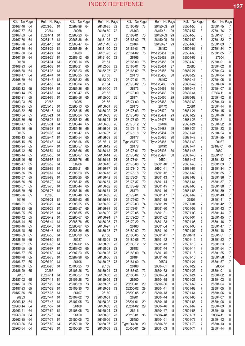
127INDEX REFERENCE
20167-46 6420167-57 6420167-69 6420167-76 6420167-78 6420167-80 6420167-88 6420167-99 64
2016820168-23 6420168-38 6420168-47 6420168-59 64
2018320183-12 6520183-14 6520183-21 6520183-23 6520183-25 6520183-32 6520183-34 6520183-36 6520183-47 6520183-56 65
2018520185-13 6520185-15 6520185-24 6520185-42 6520185-44 6520185-46 6520185-47 6520185-54 6520185-56 6520185-57 6520185-66 6520185-67 6520185-69 6520185-76 65
2018620186-21 6520186-23 6520186-25 6520186-42 6520186-44 6520186-46 6520186-48 6520186-53 6520186-55 6520186-57 6520186-65 6520186-67 6520186-78 6520186-87 6520186-89 6520186-99 65
2018720187-02 6520187-03 6520187-23 6520187-36 65
2026320263-12 6420263-14 6420263-21 6420263-23 6420263-25 6420263-36 6420263-54 64
20263-56 6420264
20264-11 6420264-13 6420264-15 6420264-22 6420264-24 6420264-26 6420264-31 6420264-33 6420264-35 6420264-44 6420264-46 6420264-55 6420264-57 6420264-66 6420264-68 64
2026520265-13 6420265-15 6420265-21 6420265-26 6420265-31 6420265-33 6420265-36 6420265-44 6420265-46 6420265-47 6420265-54 6420265-56 6420265-57 6420265-59 6420265-66 6420265-67 6420265-69 6420265-70 6420265-76 6420265-78 64
2026620266-21 6420266-22 6420266-23 6420266-25 6420266-42 6420266-44 6420266-46 6420266-48 6420266-55 6420266-59 6420266-65 6420266-67 6420266-69 6420266-78 6420266-90 6420266-96 64
2026720267-11 6420267-13 6420267-22 6420267-33 6420267-36 6420267-44 6420267-46 6420267-57 6420267-69 6420267-76 6420267-78 6420267-80 6420267-88 64
20267-99 6420268
20268-23 6420268-38 6420268-47 6420268-59 64
2028320283-12 6520283-14 6520283-21 6520283-23 6520283-25 6520283-32 6520283-34 6520283-36 6520283-47 6520283-56 65
2028520285-13 6520285-15 6520285-24 6520285-42 6520285-44 6520285-46 6520285-47 6520285-54 6520285-56 6520285-57 6520285-66 6520285-67 6520285-76 65
2028620286-21 6520286-23 6520286-25 6520286-42 6520286-44 6520286-46 6520286-48 6520286-53 6520286-55 6520286-57 6520286-65 6520286-67 6520286-78 6520286-87 6520286-89 6520286-99 65
2028720287-02 6520287-03 6520287-23 6520287-36 65
2610626106-25 7326106-26 7326106-27 7326106-28 7326106-29 7326106-30 73
2610726107-02 7326107-05 73
2610826108-05 73
2615026150-05 7226150-10 7226150-20 72
26150-25 7226150-50 72
2615126151-05 7226151-10 7226151-20 7226151-25 7226151-50 72
2615126152-06 7226152-07 72
2615326153-00 74
2615426154-00 74
2615526155-00 75
2615626156-01 7626156-02 7626156-03 7626156-04 7626156-05 7626156-06 7626156-07 7626156-08 7626156-11 7626156-12 7626156-13 7626156-14 7626156-15 7626156-16 7626156-17 7626156-18 7626156-42 7626156-51 7626156-52 7626156-61 7626156-62 7626156-81 7626156-82 7626156-91 7626156-92 7626156-94 7726156-95 7726156-97 7726156-98 77
2615826158-01 7326158-02 7326158-03 7326158-05 7326158-06 7326158-07 73
2615926159-01 7326159-03 7326159-05 7326159-07 7326159-08 73
2616026160-01 7326160-02 7326160-03 7326160-04 7326160-05 7326160-06 7326160-07 7326160-08 73
26160-09 7326163
26163-01 7526163-02 75
2616426164-01 7526164-02 75
2616526165-00 7526165-01 7526165-02 75
2617026170-01 7326170-02 73
2617326173-00 74
2617426174-00 74
2617526175-03 7226175-06 7226175-09 7226175-12 7226175-15 7226175-18 72
26177Type 26177 78
2617826178-01 7226178-02 7226178-04 7226178-08 7226178-10 7226178-18 7226178-24 7226178-37 7226178-49 72
2617926179-01 7426179-02 7426179-03 7426179-04 7426179-05 7426179-20 7426179-22 74
2618026180-02 7226180-05 7226180-06 7226180-12 72
2618326183-00 74
2618426184-00 74
2618626186-03 7326186-04 73
2620026200-01 2926200-02 2926200-05 29
2620126201-01 2926201-02 29
2621626216-01 95
26450Type 26450 29
26450-01 29
26450-03 2926450-51 2926450-53 2926450-95 2926450-97 29
2645XType 26451 30Type 26452 29Type 26453 29Type 26454 37Type 26456 30Type 26458 30
2646XType 26460 29Type 26461 30Type 26463 29Type 26466 29Type 26468 30
2647XType 26472 29Type 26474 29Type 26477 30
2648XType 26482 29Type 26484 29Type 26485 30Type 26487 30
2649XType 26495 30Type 26497 30
2650126501-10 726501-11 726501-12 726501-13 726501-14 726501-15 726501-16 726501-17 726501-18 726501-19 726501-30 726501-31 726501-32 726501-33 726501-34 726501-40 726501-41 726501-42 726501-43 726501-44 726501-45 726501-46 7
2650426504-31 826504-33 826504-34 826504-35 826504-36 826504-41 826504-43 826504-44 826504-45 826504-46 826504-47 826504-48 826504-51 826504-52 826504-53 8
26504-55 826504-57 826504-58 826504-59 826504-60 826504-61 826504-63 826504-65 826504-69 8
2668026680-21 926680-22 926680-41 926680-42 926680-43 926680-61 926680-62 926680-63 9
2668126681-21 926681-22 926681-23 926681-24 926681-25 926681-41 926681-42 926681-43 926681-44 926681-45 926681-46 926681-47 926681-48 926681-61 926681-62 926681-63 926681-64 926681-65 926681-66 926681-67 9
2750127501-01 727501-02 727501-03 727501-04 727501-05 727501-06 727501-07 727501-11 727501-12 727501-13 727501-14 727501-15 727501-16 727501-21 727501-22 727501-23 727501-24 727501-25 727501-62 727501-63 727501-64 727501-65 727501-66 727501-67 727501-68 727501-71 727501-72 727501-73 727501-74 7
27501-75 727501-76 727501-81 727501-82 727501-83 727501-84 727501-85 7
2750427504-01 827504-02 827504-03 827504-04 827504-05 827504-06 827504-07 827504-11 827504-12 827504-13 827504-14 827504-15 827504-16 827504-21 827504-22 827504-23 827504-24 827504-25 8
2816728167-01 79
2850128501-31 728501-32 728501-33 728501-34 728501-35 728501-36 728501-37 728501-38 728501-39 728501-40 728501-41 728501-42 728501-43 728501-44 728501-45 728501-46 728501-47 728501-48 728501-51 728501-52 728501-53 728501-54 728501-55 728501-56 728501-57 7
2850428504-01 828504-02 828504-03 828504-04 828504-05 828504-06 828504-07 828504-08 828504-09 828504-10 828504-11 828504-12 828504-13 828504-14 8
Réf. No Page Réf. No Page Réf. No Page Réf. No Page Réf. No Page Réf. No Page Réf. No Page Réf. No Page
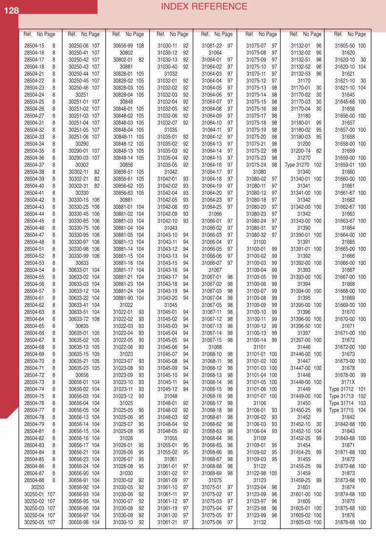
128 INDEX REFERENCE
28504-15 828504-16 828504-17 828504-18 828504-21 828504-22 828504-23 828504-24 828504-25 828504-26 828504-27 828504-31 828504-32 828504-33 828504-34 828504-35 828504-36 828504-37 828504-38 828504-39 828504-40 828504-41 828504-42 828504-43 828504-44 828504-45 828504-46 828504-47 828504-48 828504-51 828504-52 828504-53 828504-54 828504-55 828504-56 828504-57 828504-61 828504-62 828504-63 828504-64 828504-65 828504-66 828504-67 828504-68 828504-69 828504-70 828504-71 828504-72 828504-73 828504-74 828504-75 828504-76 828504-77 828504-78 828504-79 828504-81 828504-82 828504-83 828504-84 828504-85 828504-86 828504-87 828504-88 8
3025030250-01 10730250-02 10730250-03 10730250-04 10730250-05 107
30250-06 10730250-41 10730250-42 10730250-43 10730250-44 10730250-45 10730250-46 107
3025130251-01 10730251-02 10730251-03 10730251-04 10730251-05 10730251-06 107
3029030290-01 10730290-03 107
3030230302-11 8230302-21 8230302-31 82
3033030330-15 10630330-25 10630330-45 10630330-65 10630330-75 10630330-95 10630330-97 10630330-98 10630330-99 106
3063330633-01 10430633-02 10430633-03 10430633-12 10430633-22 10430633-41 10430633-51 10430633-72 108
3063530635-01 10530635-02 10530635-13 10530635-15 10530635-21 10530635-23 105
3065630656-01 10430656-02 10430656-03 10430656-04 10430656-05 10430656-13 10430656-14 10430656-15 10430656-16 10430656-17 10430656-21 10430656-23 10430656-24 10430656-90 10430656-91 10430656-92 10430656-93 10430656-95 10430656-96 10430656-97 10430656-98 104
30656-99 10830802
30802-01 8230881
30828-01 10530828-02 10530828-03 10530828-04 105
3084830848-01 10530848-02 10530848-03 10530848-04 10530848-11 10530848-12 10530848-13 10530848-14 105
3085630856-51 10530856-61 10530856-62 10530856-63 105
3088130881-01 10430881-02 10430881-03 10430881-04 10430881-05 10430881-13 10430881-14 10430881-15 10430881-16 10430881-17 10430881-21 10430881-23 10430881-24 10430881-90 104
3102231022-01 9331022-02 9331022-03 9331022-04 9331022-05 9331022-06 93
3102331023-07 9331023-08 9331023-09 9331023-10 9331023-11 9331023-12 93
3102531025-05 9531025-06 9531025-07 9531025-08 95
3102631026-01 9531026-06 9531026-07 9531026-08 95
3103031030-02 9231030-05 9231030-06 9231030-07 9231030-08 9231030-09 9231030-10 92
31030-11 9231030-12 9231030-13 9231030-40 92
3103231032-01 9231032-02 9231032-03 9231032-04 9231032-05 9231032-06 9231032-07 92
3103531035-01 9231035-02 9231035-03 9231035-04 9231035-05 92
3104231042-01 9331042-02 9331042-04 9331042-05 9331042-08 9331042-09 9331042-10 93
3104331043-10 9431043-11 9431043-12 9431043-13 9431043-15 9431043-16 9431043-17 9431043-18 9431043-19 9431043-20 94
3104531045-01 9431045-02 9431045-03 9431045-04 9431045-05 9431045-06 9431045-07 9431045-08 9431045-09 9431045-10 9431045-11 9431045-12 94
3104831048-01 9231048-02 9231048-03 9231048-04 9231048-05 92
3105531055-01 9531055-02 95
3106131061-01 9731061-02 9731061-09 9731061-10 9731061-11 9731061-12 9731061-19 9731061-20 9731061-21 97
31061-22 9731064
31064-01 9731064-02 9731064-03 9731064-04 9731064-05 9731064-06 9731064-07 9731064-08 9731064-09 9731064-10 9731064-11 9731064-12 9731064-13 9731064-14 9731064-15 9731064-16 9731064-17 9731064-18 9731064-19 9731064-20 9731064-23 9731064-25 97
3106631066-01 9731066-02 9731066-03 9731066-04 9731066-05 9731066-06 9731066-07 97
3106731067-01 9831067-02 9831067-03 9831067-04 9831067-05 9831067-11 9831067-12 9831067-13 9831067-14 9831067-15 98
3106831068-10 9831068-11 9831068-12 9831068-13 9831068-14 9831068-15 9831068-16 9831068-17 9831068-18 9831068-61 9831068-62 9831068-63 9831068-64 9831068-65 9831068-66 9831068-67 9831068-68 9831068-69 98
3107531075-01 9731075-02 9731075-03 9731075-04 9731075-05 9731075-06 97
31075-07 9731075-08 9731075-09 9731075-10 9731075-11 9731075-12 9731075-13 9831075-14 9831075-15 9831075-16 9831075-17 9831075-18 9831075-19 9831075-20 9831075-21 9831075-22 9831075-23 9831075-24 98
3108031080-02 9731080-11 9731080-12 9731080-18 9731080-20 9731080-23 9731080-24 9731080-31 9731080-32 97
3110031100-01 9931100-02 9931100-03 9931100-04 9931100-05 9931100-06 9931100-07 9931100-08 9931100-09 9931100-10 9931100-11 9931100-12 9931100-13 9931100-14 99
3110131101-01 10031101-02 10031101-03 10031101-04 10031101-05 10031101-06 10031101-07 100
3110631106-01 9331106-02 9331106-03 9331106-04 93
3110931109-01 9531109-02 9531109-03 95
3112231122-98 105
3112331123-04 9631123-09 9631123-97 9631123-98 9631123-99 96
31132
31132-01 9631132-02 9631132-51 9631132-52 9631132-53 96
3117031170-01 3031170-02 3031170-03 3031170-04 30
3118031180-01 9531180-02 9531180-03 95
3120031200-74 82
31270Type 31270 102
3134031340-01 100
3134131341-00 100
3134231342-00 100
3134231343-00 100
3139031390-01 100
3139131391-01 100
3139231392-00 100
3139331393-00 100
3139431394-00 100
3139531395-00 100
3139631396-00 10031396-50 100
3139731397-00 100
3144631446-00 100
3144731447-00 100
3144831448-00 100
3144931449-00 100
3145031450-25 99
3145231452-10 3031452-10 10431452-25 99
3145431454-25 99
3145531455-25 99
3145931459-25 99
3160131601-00 100
3160531605-01 10031605-02 10031605-03 100
31605-50 10031620
31620-10 3031620-10 104
3162131621-10 3031621-10 104
3164531645-68 100
3165631656-00 100
3165731657-00 100
3165831658-00 100
3165931659-00 10031659-01 100
3166031660-00 100
3166131661-67 100
3166231662-67 100
3166331663-67 100
3166431664-00 100
3166531665-00 100
3166631666-00 100
3166731667-00 100
3166831668-00 100
3166931669-00 100
3167031670-00 100
3167131671-00 100
3167231672-00 100
3167331673-00 100
3167831678-00 99
3171XType 31712 101Type 31713 102Type 31714 103Type 31715 104
3184231842-68 100
3184331843-68 100
3187131871-68 100
3187231872-68 100
3187331873-68 100
3187431874-68 100
3187531875-68 100
3187631876-68 100
Réf. No Page Réf. No Page Réf. No Page Réf. No Page Réf. No Page Réf. No Page Réf. No Page Réf. No Page
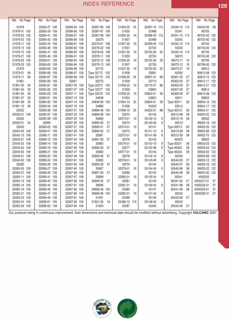
129INDEX REFERENCE
3197831978-01 10031978-02 10031978-03 10031978-11 10031978-12 10031978-13 10031978-21 10031978-22 10031978-23 100
3197931979-01 9931979-11 99
3198131981-02 3031981-04 3031981-05 3031981-07 3031981-09 3031981-10 30
3203232032-01 109
3202032020-01 24
3204532045-03 10832045-12 10832045-51 10832045-53 10832045-54 10832045-55 10832045-61 10832045-62 108
3206532065-05 10932065-07 10932065-11 10932065-13 10932065-14 10932065-16 10932065-21 10932065-23 10932065-24 10932065-26 109
32065-27 10932065-29 10932065-41 10932065-43 10932065-44 10932065-46 10932065-47 10932065-49 10932065-61 10932065-63 10932065-64 10932065-66 10932065-67 10932065-69 10932065-81 10932065-82 10932065-83 10932065-91 10932065-93 10932065-94 10932065-96 10932065-97 10932065-99 109
3206632066-05 10932066-07 10932066-11 10932066-13 10932066-14 10932066-16 10932066-21 10932066-23 10932066-24 10932066-26 10932066-27 10932066-29 10932066-41 10932066-43 10932066-44 10932066-46 10932066-47 10932066-49 10932066-61 10932066-63 109
32066-64 10932066-66 10932066-67 10932066-69 10932066-81 10932066-82 10932066-83 10932066-91 10932066-93 10932066-94 10932066-96 10932066-97 10932066-99 109
3206732067-05 10932067-07 10932067-11 10932067-13 10932067-14 10932067-16 10932067-21 10932067-23 10932067-24 10932067-26 10932067-27 10932067-29 10932067-41 10932067-43 10932067-44 10932067-46 10932067-47 10932067-49 10932067-61 10932067-63 10932067-64 10932067-66 10932067-67 10932067-69 10932067-81 10932067-82 10932067-83 10932067-91 10932067-93 10932067-94 109
32067-96 10932067-97 10932067-99 109
3207932079-01 10832079-02 10832079-03 10832079-11 10832079-12 10832079-13 108
3217XType 32172 102Type 32173 102
3227XType 32275 102Type 32277 102Type 32278 102
3484834848-99 105
3489634896-48 10534896-99 105
3589035890-00 5735890-01 5735890-02 57
3589135891-00 57
3589235892-00 57
3589335893-00 57
3589535895-00 57
3589735897-00 57
3589935899-00 57
3969639696-48 10539696-96 105
5193151931-20 19
51934
51934-20 2551935
51935-20 1951937
51937-20 1951931
51931-20 1951935
51935-20 1951937
51937-20 1951938
51938-20 2551939
51939-20 1951939
51939-20 1951954
51954-10 2551958
51958-10 2552073
52073-01 1952074
52074-01 1952075
52075-01 1952076
52076-01 1952077
52077-01 1952078
52078-01 1952079
52079-01 1952080
52080-01 1952081
52081-01 1952082
52082-01 1952486
52486-10 11352487
52487-10 11352488
52488-05 11352489
52489-05 11352704
52704-50 2552724
52724-50 2552750
52750-25 2553691
53691-01 8853710
53710-01 8853804
53804-01 3953824
53824-01 3954229
54229-01 8855140
55140-10 955140-99 9
5514155141-10 955141-99 9
5514255142-10 955142-99 9
5514355143-10 955143-99 9
5514455144-04 9
5514555145-04 9
5514655146-04 9
5514755147-04 9
5514855148-04 9
55340
55340-10 11355341
55341-10 11355342
55342-10 11355343
55343-10 11356073
56073-11 1956073-12 1956073-21 19
6030060301-00 3760302-00 3760303-00 3760307-00 3760308-00 37
60511Type 60511 58
60512Type 60512 59
60512-08 5860512-19 58
60513Type 60513 60
60513-28 5860513-39 58
6052XType 60521 58Type 60522 58Type 60523 58
6054060540-00 5760540-97 5860540-98 5860540-99 58
6054160541-00 5760541-98 5860541-99 58
6054260542-00 57
6054360543-00 57
60543-99 5880705
80705-40 12280705-60 122
8074080740-00 122
8074580745-00 122
8079980799-00 122
8081280812-08 12280812-12 12280812-17 12280812-21 122
8081480814-08 122
8083480834-12 12280834-17 12280834-21 12280834-25 122
9900299002-16 12299002-25 12299002-66 12299002-75 122
9900399003-03 12299003-04 12299003-05 12299003-08 12299003-12 12299003-16 12299003-22 12299003-30 1224500220
4500227-01 374500226-01 374500229-01 374500228-01 37
Réf. No Page Réf. No Page Réf. No Page Réf. No Page Réf. No Page Réf. No Page Réf. No Page Réf. No Page
Our products being in continuous improvement, their dimensions and technical data should be modified without advertising. Copyright VULCANIC 2007

Related Documents