ATA Specification 103 Copyright © 2006 Air Transport Association of America, Inc. All rights reserved. Output Page: 1 Spec 103 Information A TA Speci f i c at ion 103 Standard for Jet Fuel Quality Contr ol at Airp ort s Revis io n 2006. 1 Air Transport Associ ation of America, Inc. 1301 Pennsylvania Ave., N.W., Suite 1100 Washington, D.C. 20004-1707 Copyright © 2006 Air Transport Association of America, Inc. All rights reserved. No part of this document may be reproduced or transmitted by any means, electronic or mechanical, including photocopying and recording, or by any information storage or retrieval system, except as may be expressly permitted in writing by the publisher.

Welcome message from author
This document is posted to help you gain knowledge. Please leave a comment to let me know what you think about it! Share it to your friends and learn new things together.
Transcript

8/11/2019 ATA-103
http://slidepdf.com/reader/full/ata-103 1/123
ATA Specification 103
Copyright © 2006 Air Transport Association of America, Inc. All rights reserved. Output Page: 1
Spec 103 Information
ATA Specification 103
Standard for
Jet Fuel Quality Control at Airports
Revision 2006.1
Air Transport Association of America, Inc.
1301 Pennsylvania Ave., N.W., Suite 1100Washington, D.C. 20004-1707
Copyright © 2006 Air Transport Association of America, Inc. All rights reserved. No part of this document may be
reproduced or transmitted by any means, electronic or mechanical, including photocopying and recording, or by any
information storage or retrieval system, except as may be expressly permitted in writing by the publisher.

8/11/2019 ATA-103
http://slidepdf.com/reader/full/ata-103 2/123
ATA Specification 103
Copyright © 2006 Air Transport Association of America, Inc. All rights reserved. Output Page: 2
Important Information about This Document
Read Before Using This Document
This document contains recommended specifications that have been developed for the covered topics. ATA does not
mandate their use. You must decide whether or not to use the recommendations in this document. You may choose to use
them in whole, in part, or not at all.
There may be practices, standards and/or regulatory requirements applicable to your operations that exceed the
recommendations in this document. You are solely responsible for determining if such practices, standards or requirements
exist and whether they apply to your activities, and for complying with those that are applicable. Such practices, standards
and requirements can change significantly over time.
ATA does not guarantee, promise or warrant that the specifications in this document will meet the needs of your operations.
This is a determination that you must make and for which ATA is not responsible.
For Additional Information
For more information or to order additional publications, refer to the ATA Publications Catalog, the Web site at
www.airlines.org, e-mail [email protected], or call the ATA Distribution Center at:
800-497-3326 (U.S. and Canada)
301-490-7951
For Technical Information and Change Submissions
Errata information for ATA Publications is available at the ATA Publications Web page.
For technical information or to recommend an alteration or amendment to this specification, please submit therecommendation and any supporting documentation to ATA:
E-mail: [email protected]
Phone: 202-626-4062
Fax: 202-626-4181

8/11/2019 ATA-103
http://slidepdf.com/reader/full/ata-103 3/123
ATA Specification 103
Copyright © 2006 Air Transport Association of America, Inc. All rights reserved. Output Page: 3
Highlights
Release History
Revision 2006.1 (March 2006)
Revision 2004.1 (March 2004)
Revision 2000.1 (January 2000)
Revision 6 (July 1998)
Revision 5 (July 1996)
Original Issue (April, 1986)
Revision 2006.1 (March 2006)
Location Description of Change
[Section 2-1] Amended
[Section 2-3] Amended
[Section 2-4] Amended
[Section 2-5] Revised
[Section 2-6] Amended
[Section 2-7] Amended
[Section 2-8] Revised
[Section 2-9] Amended
[Section 3-3] Amended
[Section 3-10] Amended
ATA Form 103-01A [Figure 6-2.1] Revised
ATA Form 103-01B [Figure 6-2.2] Revised
ATA Form 103-01C [Figure 6-2.3] Revised
ATA Form 103-01D [Figure 6-2.4] Revised
ATA Form 103-04B [Figure 6-2.8] Revised
ATA Form 103-04C [Figure 6-2.9] Revised
ATA Form 103-07 [Figure 6-2.14] Revised
ATA Form 103-08 [Figure 6-2.15] Revised[Chapter 4] Amended
[Annex 1] Amended

8/11/2019 ATA-103
http://slidepdf.com/reader/full/ata-103 4/123
ATA Specification 103
Copyright © 2006 Air Transport Association of America, Inc. All rights reserved. Output Page: 4
Preface
This document is intended to provide guidance to the user covering the safe storage and distribution of quality jet fuel at
airports as currently practiced in the commercial aviation industry. Due to the wide diversity of airport fueling operations,
this document is not intended be all-inclusive. Technical information, along with competent judgment, should beconsidered and followed at all times when overseeing aviation fueling operations. In addition, operators should comply
with all applicable rules, regulations, restrictions, ordinances and other laws of federal, state, local and airport entities
relating to fuel storage and distribution.

8/11/2019 ATA-103
http://slidepdf.com/reader/full/ata-103 5/123
ATA Specification 103
Copyright © 2006 Air Transport Association of America, Inc. All rights reserved. Output Page: 5
Chapter 1. Introduction
Member airlines of the Air Transport Association of America (ATA) recognize the importance of using quality jet fuel for
ensuring the highest degree of flight safety. To achieve this goal, ATA Specification 103, entitled "Standard for Jet Fuel
Quality Control at Airports," was developed by member airlines to cover fuel distribution facilities and fuel quality control
procedures at airports servicing airline operations.
This standard identifies commonly recognized industry inspection procedures and safety checks of jet fuel storage and
distribution facilities at airports that will help minimize introduction of contaminated or unacceptable jet fuel from being
delivered to airline aircraft. It is important to note that additional facilities and testing procedures may be required at
individual airports based on fuel system complexity and local operating conditions. Alternative procedures and use of
non-standard facilities and equipment may also be recognized and determined acceptable for achieving the above safety
requirements based on extenuating circumstances.
ATA Specification 103 does not, in itself, impose any performance obligations on any airline, fuel supplier, fuel
storage facility, fuel transporter, or any other entity. Its provisions become effective only to the extent they are
adopted by an airline and incorporated into its operating manual.

8/11/2019 ATA-103
http://slidepdf.com/reader/full/ata-103 6/123
ATA Specification 103
Copyright © 2006 Air Transport Association of America, Inc. All rights reserved. Output Page: 6
Chapter 2. General
2-1. GeneralThis section covers jet fuel handling issues and procedures that are general in nature and are applicable to all facets of jet
fuel handling at airports.
1. Scope
This document contains standards covering airport jet fuel storage facilities, hydrant distribution systems and aircraft
refueling equipment to help ensure the safe and dependable flow of quality jet fuel to airline aircraft.
2. Records
All jet fuel quality assurance, airport facility and aircraft refueling equipment maintenance and training records are to be
available for inspection and review during normal business hours. All records must be signed, or be adequately identified,
by the person performing tasks or the person accepting responsibility that tasks were performed in accordance to this
standard.
3. Notification of New or Modified Equipment
Affected airlines are to be notified well in advance whenever new, additional, replacement or modified airport fuel storage,
distribution facilities or aircraft refueling equipment is placed into operation. At the airline's option, all airport fueling
facilities, into-plane refueling equipment and operator's procedures may be inspected and approved for use prior to
servicing airline aircraft.
4. Variance/Waiver
A variance or waiver to the policies and procedures in this document that will not compromise fuel quality, safety or
security may be granted. A request for variance or waiver must be made in writing to each affected airline and shall
include:
(a) Requirement from which the variance or waiver is being requested.
(b) Explanation as to why compliance with airline requirement is not possible or practical.
(c) Alternate means of compliance to be considered for approval of request.
(d) Period of time for which variance or waiver is to be effective.

8/11/2019 ATA-103
http://slidepdf.com/reader/full/ata-103 7/123
ATA Specification 103
Copyright © 2006 Air Transport Association of America, Inc. All rights reserved. Output Page: 7
5. Fuel Contamination
If visible contamination of fuel is observed or found, aircraft refueling must be discontinued from that source. Notify all
affected aircraft operators if it is anticipated that such contamination might impact operations. Fueling shall not be resumed
from the system until the source of fuel contamination is found and removed.
Fuel, suspected of possible contamination, shall be held in quarantine until selected fuel quality, purity or specification tests
have determined that it is acceptable for aircraft use. Selected product tests and expected acceptance criteria are to be
determined and mutually agreed upon by fueling vendor and all affected customers prior to approving fuel for future use.
To the extent the fuel is no longer acceptable for aircraft use, it should be managed and/or disposed consistent with
applicable federal, state and local requirements.
6. Defueled Product
Product defueled from an aircraft for purposes other than contamination should be returned to the airline from which it was
removed. Defueled product may not be delivered to another airline’s aircraft without their approval. Defueling aircraft
directly into joint use fueling systems is not authorized unless all system users have unanimously approved a joint use
procedure.
7. Inoperative System
If for any reason a fueling system becomes inoperative so as to impair normal refueling operations, all affected airlines
must be notified immediately.
8. Training/Qualification
Facility and fueling equipment operators are responsible for ensuring that all personnel under their direction and control are
properly trained and qualified for performing tasks assigned to them as specified in this document. Training and
qualification records are to be available for review by the airline or its designated representative.
9. Deficiency Reporting
The facility and equipment operator shall establish written procedures for the reporting of any observed deficiencies or
safety hazards by its employees to their supervisors.
10. Operations & Maintenance Manuals
All airport fueling vendors having aviation fuel storage facilities and/or aircraft refueling equipment administrative and
operational responsibilities should have operations and maintenance (O & M) manuals. These documents are intended to
be used by fuel handling vendors and equipment operators to help ensure the safe and dependable flow of quality fuel toaircraft. Guidance on the development of a site-specific O & M manual can be found in the ATA "Airport Fuel Facility
Operations and Maintenance Guidance Manual".

8/11/2019 ATA-103
http://slidepdf.com/reader/full/ata-103 8/123
ATA Specification 103
Copyright © 2006 Air Transport Association of America, Inc. All rights reserved. Output Page: 8
2-2. Jet Fuel Specification & Purity Standards
1. Specification Requirements
Jet fuel shall conform to [ASTM D1655], Latest Revision, "Standard Specification for Aviation Turbine Fuels", Jet A or Jet
A-1 Kerosene Type.
In all phases of fuel handling, appearance of jet fuel shall be clear and bright (visually free of undissolved water, sediment
and suspended matter). The odor of the fuel shall not be nauseating or irritating.
The color of jet fuel generally ranges from water white to light straw or amber. Other colors may be an indication the fuel
has been contaminated by other products or unauthorized additives. In such cases, it shall be the facility operator's
responsibility to discontinue fuel transfer and/or quarantine product until fuel has been determined acceptable for aircraft
use.
2. Upstream Jet Fuel Purity and Specification Parameters
The following jet fuel purity and specification parameters should apply UPSTREAM of airport receiving filtration.
Table 2-2.1. Jet Fuel Purity and Specifi cation Parameters
Test Property Maximum Allowable Test Method
APPEARANCE CLEAR & BRIGHT VISUAL
Ref. [Section 3-1]
DENSITY
(API GRAVITY)
37° TO 51° API (775-840 Kg/m3)
Corrected to 60° F (15° C)
[ASTM D1298]
Metric measurement shall be used
in event of dispute (775-840Kg/m3).
NOTE: It is important that the facility operator assigned the task and responsibility to receive jet fuel into
airport storage tanks sample inbound deliveries upstream of receiving filtration for potential
contamination or excessive water/dirt levels. Inbound jet fuel purity shall permit reasonable receiving
filtration system performance and service life. Upstream appearance ratings less than Clear & Bright
may indicate excessive contamination levels which could result in shortened receiving filtration life and
may increase operational costs. Unacceptable operational and economic issues based on upstream jet
fuel purity levels are to be resolved between applicable shipper, facility operator and/or customer.

8/11/2019 ATA-103
http://slidepdf.com/reader/full/ata-103 9/123
ATA Specification 103
Copyright © 2006 Air Transport Association of America, Inc. All rights reserved. Output Page: 9
3. Downstream Jet Fuel Purity and Specif ication Parameters
The following jet fuel purity and specification limits shall apply DOWNSTREAM of the receiving and dispensing
filtration as:
1. Received into airport storage tanks and dispensed from airport storage facilities which will issue product directlyto hydrant systems and to aircraft refueler loading racks
2. Dispensed into aircraft
See rejection criteria in reference NOTES or in [Section 2-3] for applicable transportation methods:
Table 2-2.2. Downstream Jet Fuel Purity and Specification Limits
Test Property Maximum Allowable Test Method See Notes
FREE WATER 15 PPM Ref. [Section 3-3]
PARTICULATE
COLOR*
A, B or G 2 - DRY or A, B or G 3 -
WET
[ASTM D2276] 1
PARTICLE
ASSESSMENT*
A VISUAL 2
* Sample sizes are either 1 Gallon or 5 Liter
NOTE 1. A color rating of 3-DRY or greater may indicate a particulate contaminant problem. If a color rating of
3-DRY or greater is observed, proceed as follows:
Perform a subsequent particulate test consisting of two membranes in plastic holder to compare color
difference between top and bottom membranes. If top and bottom membranes have a color rating
difference of 2 or less, fuel is to be considered clean and acceptable. If difference is 3 or greater,
conduct a gravimetric (weight) analysis. Fuel is unacceptable if gravimetric test ([ASTM D2276])
results exceed 2.0 mg/G or 0.5 mg/L based on test sample size taken.
NOTE 2. An assessment rating of "B" or greater (reference Gammon Technical Products SGTP-3940 "Color and
Particle Assessment Rating Guide" or Shell Oil Company "Filter Membrane Evaluation Guide")
indicates that solid particles are visible on the test membrane or in the sample container. This
observation may be an indication that there is generation of contamination in system or failure of
filtration upstream of sample test connection. Particle Assessment is an aid in communicating visual
observations of size and distribution of solids as they appear on test membranes or the bottom of
sample containers.

8/11/2019 ATA-103
http://slidepdf.com/reader/full/ata-103 10/123
ATA Specification 103
Copyright © 2006 Air Transport Association of America, Inc. All rights reserved. Output Page: 10
2-3. Fuel Receipts Into Airport Storage
1. General
This section covers quality control and safety requirements for receiving jet fuel into airport storage. These requirements
can vary depending on method of delivery and facility layout. Receipts of jet fuel at airports are normally made by
dedicated or multi-product pipelines, and highway transport trucks. There are some airports receiving product directly
from railroad tank cars or marine vessels. It is important that facility operator recognizes that each of these transportation
methods has different delivery requirements and that they be addressed in local receiving procedures to ensure fuel quality
and safety.
2. Pipeline Deliveries
Prior to delivery, airport facility operator shall receive a certification document from jet fuel supplier or shipping agent
certifying product to be delivered to airport meets [ASTM D1655] specification requirements as required in [Section 2-2]
with at least the following select property values listed as measured by specified ASTM test methods:
(a) Visual Appearance in White Bucket Ref. [Section 3-1]
(b) Gravity, Corrected to 60° F (15° C) [ASTM D1298]
(c) Distillation
10% Recovered
20% Recovered
50% Recovered
90% Recovered
Final Boiling Point
Residue
Loss
[ASTM D86]
(d) Flash Point [ASTM D56]
(e) Freezing Point [ASTM D2386]
(f) Water Reaction Interface Rating [ASTM D1094]
(g) Water Separation (MSEP) [ASTM D3948]
(h) Copper Strip Corrosion [ASTM D130]
(i) Existent Gum [ASTM D381]
Shipping document shall also include all delivery information, i.e.: destination; batch number; fuel grade or type; quantity
to be shipped.
NOTE Fuel receipts should not be rejected based on incomplete certification documentation. If thecertification documentation cannot be delivered prior to delivery, affected airlines must be notified.
Facility operator shall prepare receiving tank(s) and facility items prior to delivery of product, i.e.: gauging, sumping,
correct inlet and outlet valve positioning, etc. The facility operator must ensure that the volume available in the receiving
tank(s) is greater than the volume of product to be transferred to the tank(s) before the transfer is made.

8/11/2019 ATA-103
http://slidepdf.com/reader/full/ata-103 11/123
ATA Specification 103
Copyright © 2006 Air Transport Association of America, Inc. All rights reserved. Output Page: 11
Fuel receiving process must be monitored constantly by airport facility personnel, and such personnel must be able to
communicate with the pipeline company during fuel receipt.
CAUTION: IT IS NOT ACCEPTABLE TO RECEIVE AND DISPENSE FUEL FROM THE SAME TANK
SIMULTANEOUSLY
At the beginning, mid-point and near the end of fuel receipts, the facility operator shall conduct the following tests on fuel
samples taken downstream of receiving filtration and record the results. This series of tests is to be repeated for each
shipper tank or batch. The mid-point test may be omitted on shipments of less than four hours in duration.
(a) Visual Appearance in White Bucket
(b) API Gravity, Corrected to 60° F (15° C)
(c) Color Membrane (Particulate weight to be performed only if necessary per Note 1 of 2-2.3)
(d) Free Water Detection Test
(e) Flash Point (Multi-Product Pipeline Deliveries Only)
NOTE 1. Operators should be aware that pipeline volumes between shipping tanks and sampling points may be
from a previous batch. Fuel tests should be timed to coincide with actual arrival of product from
shipping tank.
NOTE 2. If any of the above receiving tests fail reject limits, product in receiving tank(s) must be quarantined
and not released for aircraft use pending further investigation and corrective actions as required.
NOTE 3. Use extreme care and vigilance when performing the Visual Appearance test. Slight traces of water,
solids or color may indicate the presence of product mixes or other contaminants that could cause jet
fuel to be off-specification and unacceptable for aircraft use. Any unusual results must be investigated.
Fuel is unacceptable and must be rejected if API Gravity, corrected to 60° F (15° C), is not between 37° and 51° API
(775-840 Kg/m3) and/or Flash Point is less than 100° F (38° C). Discontinue fuel transfer or receipt and initiate an
immediate investigation to determine if there is fuel contamination or a specification problem if there is a change of more
than 1° API or 5° F (3° C) in Flash Point from source as shown on shipping document.
If a certification document was not obtained prior to receipt, into airport storage, via a Multi-Product pipeline, the facility
operator should immediately conduct the following [ASTM D1655] property tests prior to releasing the tank for aircraft
use. Fuel not meeting [ASTM D1655] specification is to be rejected.

8/11/2019 ATA-103
http://slidepdf.com/reader/full/ata-103 12/123
ATA Specification 103
Copyright © 2006 Air Transport Association of America, Inc. All rights reserved. Output Page: 12
Table 2-3.1. ASTM D1655 Property Test
PROPERTY SPEC LIMIT MAX DIFFERENCE
(a) Visual Appearance in White Bucket Clear & Bright
(b) Gravity, Corrected to 60° F (15° C) 37° to 51° API (775-840Kg/m3) 1° API
(c) Distillation
10% Recovered 400° F (205° C) 14° F (8° C)
20% Recovered Report 14° F (8° C)
50% Recovered Report 14° F (8° C)
90% Recovered Report 14° F (8° C)
Final Boiling Point 572° F (300° C) 14° F (8° C)
Residue 1.5 Spec Limit
Loss 1.5 Spec Limit
(d) Flash Point 100° F (38° C) 5° F (3° C)
(e) Freezing Point
Jet A -40° F (-40° C) 5° F (3° C)
Jet A-1 -53° F (-47° C) 5° F (3° C)
(f) Water Reaction: Interface Rating 1b Spec Limit
(g) Water Separation (MSEP) 85 min Spec Limit
(h) Copper Corrosion Strip No. 1 max Spec Limit
(i) Existent Gum 7 max Spec Limit
NOTE: Pipelines are considered "dedicated" only if they do not have inlet connections to any other product
from the last tank or point the fuel was completely recertified as jet fuel meeting [ASTM D1655]
specification. There is a significant increase in exposure to fuel contamination problems when airports
receive jet fuel by "multi-product" pipelines as compared to "dedicated" pipelines. Additional care
must be taken to prevent the deterioration of fuel quality.
While receiving fuel into airport storage, the facility operator is to periodically monitor pressure differential of inlet
filtration, tank fill levels and check system for product leaks.
Upon completion of fuel receipt into airport storage, the facility operator should secure receiving tank(s) and facility items,
i.e.: gauging, record results of sumping tanks and filters, set inlet and outlet valves for correct positioning, etc. Tank and
filter sump results are to be recorded and retained for 12 months.
NOTE: It is desirable to have one hour settling per vertical foot of product depth.

8/11/2019 ATA-103
http://slidepdf.com/reader/full/ata-103 13/123
ATA Specification 103
Copyright © 2006 Air Transport Association of America, Inc. All rights reserved. Output Page: 13
3. Transport Truck Deliveries
Airport facility operator shall receive a certification document from jet fuel supplier or shipping agent certifying product to
be delivered to airport meets [ASTM D1655] specification requirements required in [Section 2-2] with at least the
following select property values listed as measured by specified ASTM test methods (Ref. [Table 2-3.1] "ASTM D1655
Property Test" for Min./Max. Spec. Limits). A single certification document can represent multiple transport truck deliveries:
(a) Visual Appearance in White Bucket Ref. [Section 3-1]
(b) Gravity, Corrected to 60° F (15° C) [ASTM D1298]
(c) Distillation
10% Recovered
20% Recovered
50% Recovered
90% Recovered
Final Boiling Point
Residue Loss
[ASTM D86]
(d) Flash Point [ASTM D56]
(e) Freezing Point [ASTM D2386]
(f) Water Reaction Interface Rating [ASTM D1094]
(g) Water Separation (MSEP) [ASTM D3948]
(h) Copper Strip Corrosion [ASTM D130]
(i) Existent Gum [ASTM D381]
Accompanying documentation shall also include all delivery information, i.e.: destination; batch number; fuel grade or
type; quantity to be shipped.
NOTE: Fuel receipts should not be rejected based on incomplete certification documentation. If the
certification documentation cannot be delivered prior to delivery, affected airlines must be notified.
Facility operator shall prepare receiving tank(s) and facility items prior to delivery of product, i.e., gauging, sumping,
correct inlet and outlet valve positioning, etc
At time of delivery and prior to connecting truck discharge hoses, transport truck driver and facility operator are to review
and agree that fuel delivery documentation and procedures are in place to ensure satisfactory fuel receipt.
Truck unloading hoses and fittings are to be inspected for deficiencies, pending failures and cleanliness prior to connection
to airport facility receiving connections..
Prior to testing and unloading of the transport truck, allow truck to sit for a minimum of 10 minutes with the tank internal
valves open.

8/11/2019 ATA-103
http://slidepdf.com/reader/full/ata-103 14/123
ATA Specification 103
Copyright © 2006 Air Transport Association of America, Inc. All rights reserved. Output Page: 14
Facility operator shall conduct the following tests on fuel samples received from each highway transport truck tank
compartment and record the results:
(a) Visual Appearance in White Bucket
(b) API Gravity, corrected to 60° F (15° C)
NOTE: Use extreme care and vigilance when performing the Visual Appearance test. Slight traces of water,
solids or color may indicate the presence of product mixes or other contaminants that could cause jet
fuel to be off-specification and unacceptable for aircraft use. Any unusual results must be investigated
If visible contamination is observed in white bucket, more than one sumping may be required to clear it. If contamination
remains after five (5) one gallon individual samples from one tank truck compartment, the load must be rejected. If a load
is rejected, affected aircraft operators are to be notified if it is anticipated that such rejections may impact aircraft
operations. A representative sample of the rejected product, including supporting documentation, shall be retained in a
clean container for a minimum of 30 days for future reference. Documentation shall include copy of Bill of Lading,
truck/trailer number and reason for rejection.
Fuel is unacceptable and must be rejected if API Gravity, corrected to 60° F (15° C), is not between 37° and 51° API
(775-840 Kg/m3). Discontinue fuel transfer or receipt and initiate an immediate investigation to determine if there is fuel
contamination or a specification problem if there is a change of more than 1° API from source as shown on shipping
document.
While receiving fuel into airport storage, facility operator is to periodically monitor pressure differential of inlet filtration
and check system for product leaks. Fuel receiving process must be monitored constantly by airport facility personnel.
CAUTION: IT IS NOT ACCEPTABLE TO RECEIVE AND DISPENSE FUEL FROM THE SAME TANK
SIMULTANEOUSLY
Upon completion of receipt by transport truck, facility operator shall;
Close inlet valve(s) on receipt tank(s).
Sump each receiving filter vessel. (Sumping of inbound filter vessels, after each transport truck receipt, will assist
facility operator in identifying a particular delivery of product, which may have contained unacceptable levels of
water prior to off-loading, but which were undetectable during initial visual receiving checks.).

8/11/2019 ATA-103
http://slidepdf.com/reader/full/ata-103 15/123
ATA Specification 103
Copyright © 2006 Air Transport Association of America, Inc. All rights reserved. Output Page: 15
Sump tank(s) in which product was received. (A minimum of 1 hour between the end of transport truck receiving
and storage tank sumping is recommended to allow any water and/or solids stirred up during tank receiving to
settle to the tank sump for removal.).
Record the results of each sump.
NOTE 1: It is recognized that many facilities receive fuel via simultaneous off-loading of transport trucks,
making sumping, of inbound filter vessels, after each individual delivery, unfeasible. Therefore,
multiple deliveries into a product receiving tank, during a single day, may be considered a single
receipt, provided the tank does not change from receipt to delivery status during that period.
NOTE 2: It is desirable to have one hour settling per vertical foot of product depth.
Retain fuel receiving records for 12 months.
4. Railroad Tank Car Deliveries
Airport facility operator should follow the "TRANSPORT TRUCK DELIVERIES" section for guidance procedures.
5. Marine Vessel Deliveries
Airport facility operator should follow the "PIPELINE DELIVERIES" section for guidance procedures.

8/11/2019 ATA-103
http://slidepdf.com/reader/full/ata-103 16/123
ATA Specification 103
Copyright © 2006 Air Transport Association of America, Inc. All rights reserved. Output Page: 16
2-4. Fuel Storage Faci lity Requirements
1. General
Fuel storage facilities which will supply fuel directly into aircraft, refuelers, or hydrant systems must meet the following
requirements, unless otherwise indicated. Vendors with facilities that do not meet the requirements of this section shall
submit a waiver request to the affected customers under subsection 2-1.4 of this standard. Examples of Waiver/Variance
may be found in [Section 5-1] and [Section 5-2].
CAUTION: ZINC GALVANIZED MATERIALS MUST NOT BE USED IN JET FUEL SERVICE. NO COPPER
ALLOYS, CADMIUM PLATING OR PLASTIC MATERIALS ARE PERMITTED FOR MAIN
FUEL PIPING. THE USE OF COPPER OR COPPER ALLOY MATERIALS FOR OTHER
COMPONENTS MUST BE MINIMIZED.
2. Storage Tanks
Storage tanks shall include the following equipment;
(a) Floating suction with means of verifying proper operation.
(b) Inlet diffuser
(c) Gauge hatch with slotted tube
(d) Access manway (Two are preferred)
(e) Automatic high liquid level device(s) to prevent tank overfill.
(f) Suitable secondary containment as applicable.
(g) A placard, adjacent to tank sump drain(s), indicating the volume of tank drain piping.
Above ground vertical tanks shall also adhere to the following, in addition to 2-4.2. (a) thru (g), above, unless otherwise
indicated;
(a) Fixed roof
(b) Light color epoxy coated floor and sides up to the top of the first wall panel. Complete internal coating is
recommended.
(c) Cone down bottom to positive center sump with drain. Floor plates shall be arranged to ensure water run-off.
Slope of 1 in 20 is recommended.
(d) Non-Metallic tanks are not acceptable.
Above ground horizontal tanks shall also adhere to the following, in addition to 2-4.2. (a) thru (g), above, unless otherwise
indicated;
(a) Carbon steel tanks must have complete internal light colored epoxy coating.

8/11/2019 ATA-103
http://slidepdf.com/reader/full/ata-103 17/123
ATA Specification 103
Copyright © 2006 Air Transport Association of America, Inc. All rights reserved. Output Page: 17
(b) Sloped bottom to positive sump with drain.
Slope of 1 in 20 is recommended.
(c) Non-Metallic tanks are not acceptable.
(d) Access manways should be equipped with an internal ladder.
Underground tanks shall also adhere to the following , in addition to 2-4.2. (a) thru (g), above, unless otherwise indicated;
(a) Carbon steel tanks must have complete internal light colored epoxy coating.
(b) Access manways should be equipped with an internal ladder.
(c) Manways and other tank appurtenances must be extended above ground.
(d) Sloped bottom to positive sump with permanent pump.
Slope of 1 in 20 is recommended.
3. Filters
Filter/Separators are required for receiving fuel into and dispensing fuel from storage which will supply fuel directly into
aircraft, refuelers, or hydrant systems. If only one Filter/Separator is available, it must be installed to perform both fuel
receiving and dispensing functions.
CAUTION: FULL FLOW MONITORS SHOULD NOT BE USED WITH FUELS CONTAINING FUEL
SYSTEM ICING INHIBITORS (FSII). THE WATER REMOVAL PERFORMANCE OF FULL
FLOW MONITORS MAY BE REDUCED WITH FUEL CONTAINING FSII.
NOTE 1: Full flow monitors meeting the requirements of [IP 1583] may be used in lieu of Filter/Separators with
water defense systems.
NOTE 2: Additional filtration, such as micronic filters, water coalescers (haypacks) or clay treaters, may be
required due to local conditions. If micronic filters are used, they must meet the qualification
requirements of [API/IP 1590].
NOTE 3: An API monogram is not necessary to meet the requirements of this document.
All new vessels and element combinations shall meet [API/IP 1581] latest edition. Existing vessels and element
conversions shall meet, by test or similarity, the latest edition of [API/IP 1581] / [API/IP 1582]. For existing vessels,
conversion to the latest edition shall occur within 12 months of qualified elements becoming available for a specific vessel.
If qualified by similarity, a similarity data sheet must be maintained locally and a data plate reflecting such qualificationmust be attached to the filter vessel.
Filter/Separators must be equipped with an automatic water defense system that will stop fuel flow or alert operating
personnel when actuated by a high water level.
Float or electronic probe systems must include provisions for an operational test.

8/11/2019 ATA-103
http://slidepdf.com/reader/full/ata-103 18/123
ATA Specification 103
Copyright © 2006 Air Transport Association of America, Inc. All rights reserved. Output Page: 18
All filter vessels must be equipped with:
(a) Provisions for the elimination of air
(b) Direct reading differential pressure gauges with an accuracy of +/- 2 PSI
(c) Manual sump drains - Valves with handles spring loaded to the closed position are recommended.
(d) Upstream and downstream sampling (Millipore) connections, including probes and dust caps or plugs.
(e) Pressure relief valves
(f) Placard indicating month and year of last filter change.
Use of automatic water drain valves is not recommended. Existing automatic drain valves should be removed.
4. Physically Segregated Systems
Physically segregated systems are required where more than one grade of fuel is stored to prevent accidental mixing of
products.
Isolation valves and/or blind flanges are not acceptable methods of product grade separation.
Connections for receiving and dispensing different grades of fuel must be physically incompatible.
5. Emergency Fuel Shutoff System
An emergency fuel shutoff system is required
Emergency shutoff valves and switches must be clearly marked in accordance with the requirements of [NFPA 407], latest
edition, and the area around them must be kept free of obstructions.
6. Fire Extinguishers With Inspection Tags
Fire extinguishers with inspection tags must be positioned in accordance with applicable safety requirements.
7. Fuel Loading and Unloading Hoses
Loading hoses and couplings must meet the following standard when purchased by the end user.
[API 1529], Grade 2, Type C, latest edition.
Hoses shall be installed within 2 years of the date of manufacture, and have a maximum service life of 10 years from the
date of manufacture.
If reusable couplings are installed on loading/unloading hoses the couplings and hose shall meet the requirements of [API
1529] and operator shall abide by the testing requirements of [API/IP 1540], latest edition.
Operators choosing to reattach couplings must undergo training from the hose or coupling manufacturer.

8/11/2019 ATA-103
http://slidepdf.com/reader/full/ata-103 19/123
ATA Specification 103
Copyright © 2006 Air Transport Association of America, Inc. All rights reserved. Output Page: 19
CAUTION: PRIOR TO THE PERIODIC PRESSURE TESTING OF A FUEL LOADING HOSE, THE
MAXIMUM ALLOWABLE PRESSURE RATING OF THE ATTACHED VALVES, METERS, OR
SWIVELS SHOULD BE CHECKED TO PREVENT POSSIBLE INJURY TO THE OPERATOR OR
DAMAGE TO THE EQUIPMENT. IT MAY BE NECESSARY TO REMOVE THE FUELING HOSE
PRIOR TO TESTING. FOLLOWING THE SAFETY PRECAUTIONS OUTLINED IN [API/IP 1540]
IS HIGHLY RECOMMENDED.
Fuel "unloading" hoses shall be compatible with jet fuel and suitable for local conditions. Dust covers or other protective
devices must be used to keep out dirt and water.
8. "No Smoking" , "Flammable" , and Product Identification Signs
"NO SMOKING", "FLAMMABLE", and product identification signs must be prominently displayed.
9. Facil ity Identif ication and Color Coding
Fuel storage facilities must be properly identified and color coded in accordance with the standards of [API/IP 1542], latestedition.
10. Metal Underground Tanks and Piping
Metal underground tanks and piping must be cathodically protected.
11. Relaxation Chambers
Relaxation chambers, where installed, shall be equipped with the following:
(a) Air eliminator
(b) Protection by pressure relief valve
(c) Manual sump drain - Valves with handles spring loaded to the closed position are recommended.
12. Bulk Air Eliminator
Bulk air eliminators, where installed, shall be equipped with the following:
(a) Protection by pressure relief valve
(b) Manual sump drain
13. Refueling Truck Loading Station
A handheld deadman control device is required for all truck loading operations, per NFPA 407. Bottom loading control
systems do not negate the need to bond with a separate bonding cable.
Loading station must be equipped with pressure control provisions if necessary to prevent damage to the refueling truck
during high level shutdown of truck mounted valves.

8/11/2019 ATA-103
http://slidepdf.com/reader/full/ata-103 20/123

8/11/2019 ATA-103
http://slidepdf.com/reader/full/ata-103 21/123
ATA Specification 103
Copyright © 2006 Air Transport Association of America, Inc. All rights reserved. Output Page: 21
2-5. Fuel Faci lity Checks
1. General
The following checks must be performed on all fuel storage facilities servicing aircraft and at the frequencies specified.
Additional tasks or more frequent checks may be required based on local conditions.
Daily checks and inspections should be made at the beginning of each work day including weekends and holidays.
Maintenance requirements specified in this section are generally limited to those items pertaining to fuel quality and safety.
Additional programs should be established to ensure mechanical reliability of all facility equipment . Any facility
equipment not in daily use must have all daily, monthly, quarterly and annual checks current and recorded before the
equipment is returned to service.
8/11/2019 ATA-103
http://slidepdf.com/reader/full/ata-103 22/123
ATA Specification 103
Copyright © 2006 Air Transport Association of America, Inc. All rights reserved. Output Page: 22
2. Facil ity Check Records
Records, paper or electronic, must be completed by the person performing the tasks, or by the person accepting
responsibility for performance of the tasks.
Use of Forms 103.01, A through D, is recommended, but not required. No variance authority is needed to use other forms
if they meet or exceed the task and frequency requirements specified in this section. Additional copies of Forms 103.01, A
through D, may be reproduced locally (See [Section 6-2]).
The legible signature, initials or employee identification number of the person performing the tasks or the person accepting
responsibility for the performance of the tasks is required.
(a) If initials or employee identification numbers are used, a record of each person’s name and initials/identification
number must be maintained and available for review.
(b) Supporting documentation, completed by the person actually performing the tasks and containing their signature,
initials or identification number must be available if another person has accepted responsibility for
accomplishment of the tasks.
Records must indicate when fueling equipment is not used. Retain records in local files as follows:
Daily, Quarterly, Semi-Annual, and Annual check records – 12 months
Filter Change records – 36 months
Tank Inspection and Cleaning records - Indefinitely
Upon completion of the checks, record results using the following condition codes:
S = Indicates Satisfactory
C = Indicates Comment. Comment required in remarks section. Corrective action must be documented and dated.
N/U = Indicates unit Not Used
N/A = Indicates Task Not Applicable
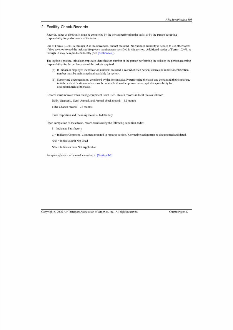
Sump samples are to be rated according to [Section 3-1].

8/11/2019 ATA-103
http://slidepdf.com/reader/full/ata-103 23/123
ATA Specification 103
Copyright © 2006 Air Transport Association of America, Inc. All rights reserved. Output Page: 23
3. Daily Checks
3.1. General Condition of Tank Yard
(a) Check the general condition of the yard area for appearance and cleanliness. Report and correct any condition that
needs immediate attention, i.e., plugged drainage, weeds, poor housekeeping, etc.
(b) Evidence of any recent fuel spill, including, but not limited to, staining, strong fuel odors or the presence of fuel in
catchment basins, overflow tanks, oil/water separators, or sumps, must be investigated immediately.
3.2. Secur ity, Fire & Safety Deficiencies
(a) Check tank yard and fuel handling facilities for any security, fire or safety deficiencies or unusual conditions
requiring immediate corrective actions.
(b) Fuel Leaks
Check tanks, piping, valves, hoses, meters, filters, and other fuel handling equipment for fuel leaks.
Any visible leaks must be immediately reported and repaired.
(c) Ensure that all gates and access doors are kept locked when area is unattended.
(d) All broken fences and gates are to be repaired or replaced immediately.
(e) In unsecured areas, all tank openings, valves, sump drains, fill caps, monitoring ports, loading/unloading hoses,
master electrical switches and other accessible fittings must be kept closed and locked at all times when not in use.
3.3. Storage Tank and Product Reclamation Tank Sumps
(a) Drain fuel, at maximum practical flow, into suitable container (Ref. [Section 3-1]). Sample quantity shall be of
sufficient size to ensure displacement of sampling line volume.
(b) Perform fuel appearance test of sample.
(c) Record findings of first sample taken, after displacement of sampling line volume, according to [Section 3-1].
(d) Continue draining until clean, dry fuel is obtained.
(e) Remove tank from service if unable to obtain clean, dry fuel. Report unusual contamination to aircraft operators if
it is anticipated that such contamination may impact aircraft operations.
3.4. Filter Sumps
(a) Drain fuel, at maximum practical flow, into suitable container (Ref. [Section 3-1]). Vessel must be pressurized,
but fuel does not have to be flowing through vessel when sample is taken.
(b) Perform fuel appearance test of sample.
(c) Record findings of first sample taken, after displacement of sampling line volume, according to [Section 3-1].
(d) Remove filter vessel from service if unable to obtain clean, dry fuel. Report unusual contamination to aircraft
operators if it is anticipated that such contamination may impact aircraft operations.

8/11/2019 ATA-103
http://slidepdf.com/reader/full/ata-103 24/123
ATA Specification 103
Copyright © 2006 Air Transport Association of America, Inc. All rights reserved. Output Page: 24
3.5. Filter Differential Pressure
Under normal flow conditions, check and record differential pressure across all working filters (Ref. [Section 3-9]).
3.6. Hoses, Swivels, Nozzles & Couplers(a) Check condition of all fuel hoses, swivels, nozzles and couplers for wear, damage and leakage.
(b) Ensure dust covers or other protective devices are available, installed and in good repair.
1) Check hoses for abrasions, cuts, soft spots, carcass separation, worn covers, blisters, exposed reinforcement,
cracks, twists and sharp bends that give the appearance of pending failure.
2) Check tightness of all swivel attachment screws and hose couplings.
3) Check condition of nose and poppet seals on nozzles/couplers for cuts, nicks and wear.
(c) Any item that is defective or is leaking must be replaced or repaired immediately.
3.7. Static Reels, Cables & Clamps
(a) Check condition of static reels, cables and clamps.
(b) Any defect that affects continuity must be corrected prior to use.
NOTE: Continuity must be checked after maintenance to static bonding systems.
3.8. Fire Extinguishers
(a) Verify that fire extinguishers:
1) Are located in their designated place
2) Have unobstructed access and visibility
3) Are tagged to indicate monthly inspections are current
4) Have unbroken safety seals or tamper indicators
5) Have no obvious physical damage, corrosion or leakage
6) When so equipped, the pressure gauge reading or indicator is in the operable range or position
(b) If any fire extinguisher is missing or does not meet the criteria listed above, it shall be repaired, or removed from
service and replaced with a serviceable extinguisher of the same or greater capacity.

8/11/2019 ATA-103
http://slidepdf.com/reader/full/ata-103 25/123
ATA Specification 103
Copyright © 2006 Air Transport Association of America, Inc. All rights reserved. Output Page: 25
4. Monthly Checks
4.1. Filtration & Free Water Test (Mill ipore)
Perform a membrane color/particle (Millipore) and free water test downstream of all filter/separator vessels (Ref. [Section3-2] and [Section 3-3]). Record results and attach test membrane to Form 103.08 or equal.
4.2. Bonding Cable Continuity
Perform electrical continuity check on bonding cables and clamps (Ref. [Section 3-10]).
Resistance must be 25 ohms or less.
Defective equipment must be repaired prior to fuel transfer.
4.3. Nozzle Screens
(a) Remove nozzles and examine screens for particles or damage.
If particles are found, investigate sources of contamination which could be from inner hose lining, pipe rust,
sand, low point sediment, equipment failure, seals, gaskets, etc.
(b) Screens are to be cleaned if contaminated or replaced if damaged.
4.4. Signs, Labels & Placards
Verify that fueling equipment is clearly marked with the proper type of fuel being dispensed, flammable, no smoking,
emergency shutoff and other appropriate information and instructions, signs or labels as required.
4.5. Floating Suctions
Verify satisfactory operation of all tank floating suctions.
4.6. Fire Extinguishers
(a) Check each fire extinguisher for inspection tag and seal.
(b) Maintain extinguishers in accordance with the applicable [NFPA 10] guidelines.
(c) Upon completion of the inspection, update inspection tag.

8/11/2019 ATA-103
http://slidepdf.com/reader/full/ata-103 26/123
ATA Specification 103
Copyright © 2006 Air Transport Association of America, Inc. All rights reserved. Output Page: 26
5. Quarterly Checks
5.1. Emergency Shutoff System
(a) Operationally check the emergency shutoff system.
1) Coordinate shutoff test with all persons, agents, airlines, fuel suppliers, and other groups having interest in the
operation of the system.
2) Each control device must be tested at least once a year.
(b) Immediately report any operational discrepancies.
5.2. Water Defense System - External Checks
Check operation of water defense systems in accordance with quarterly requirements of [Section 3-12].
5.3. Tank High Level Controls(a) Check satisfactory operation of tank high level sensing devices and automatic fuel flow shutoff valves where
installed.
(b) Inoperative controls should be adjusted or repaired immediately or have alternate operating procedures in effect
that will provide positive spill prevention while tank is in service.

8/11/2019 ATA-103
http://slidepdf.com/reader/full/ata-103 27/123
ATA Specification 103
Copyright © 2006 Air Transport Association of America, Inc. All rights reserved. Output Page: 27
5.4. Product Reclamation Tank Interior Inspection
On a quarterly basis product reclamation tanks must be visually inspected for cleanliness or pass a microbiological growth
test, as recommended, by the affected airlines. Clean as required (Ref. [Section 3-11]).
6. Semi-Annual Check
6.1. Hose Pressure Checks
(a) Loading/unloading hoses fitted with reusable couplings, and being operated under system pressure, must undergo
the six-month pressure testing at 225 PSI, per the requirements found in [API/IP 1540].
NOTE: Pressure testing to 300 PSI is required whenever a new hose attachment or coupling is fitted
CAUTION: RECOUPLING AND PRESSURE TESTING OF HOSES AND FITTINGS SHOULD ONLY BE
CARRIED OUT BY PERSONS ADEQUATELY TRAINED IN THEIR PROPER FITTINGS AND
TESTING, AND APPROVED BY THE OEM.
7. Annual Checks
7.1. Storage Tank Interiors
(a) Check fuel storage tank interiors for cleanliness and condition of coating.
(b) Clean as required ( Ref. [Section 3-11] ).
7.2. Filter Differential Pressure Gauges
Verify proper operation of filter differential pressure gauge(s) in accordance with gauge manufacturers’ procedures.
Accuracy must be within +/- 2 PSI. Repair or replace as required. (Ref. [Section 3-9])
7.3. Filter Elements
(a) Change filter elements per [Section 3-13].
(b) Replace filter elements per criteria found in [Section 3-14].
(c) All filter vessels must be opened annually to visually check condition of interior for cleanliness, and integrity of
elements.

8/11/2019 ATA-103
http://slidepdf.com/reader/full/ata-103 28/123
ATA Specification 103
Copyright © 2006 Air Transport Association of America, Inc. All rights reserved. Output Page: 28
7.4. Filter/Separator Heaters
Where installed, check filter/separator sump and drain line heaters for proper operation per manufacturer specifications
before freezing weather.
7.5. Tank Vents
(a) Where installed, check cleanliness of tank vent screens.
Clean, repair or replace vent screens as required.
(b) Tanks that have pressure/vacuum vents, check satisfactory operation and condition of poppets and inlet screens.
Under freezing conditions, additional checks may be required to assure free movement of poppets.
7.6. Cathodic Protection
Where installed, confirm satisfactory operation of cathodic protection systems. This requirement is generally contracted to businesses specializing in this type of service. State or local regulations may require greater frequency of inspection.
7.7. Line Strainers
(a) If installed, check line strainers for cleanliness and damage.
(b) Clean or replace screens as required.
(c) Local conditions may require more frequent check of some strainers, such as those used for truck unloading.
7.8. Water Defense System Inspection & Test
Check operation of water defense systems in accordance with annual requirements of [Section 3-12]

8/11/2019 ATA-103
http://slidepdf.com/reader/full/ata-103 29/123
ATA Specification 103
Copyright © 2006 Air Transport Association of America, Inc. All rights reserved. Output Page: 29
2-6. Hydrant System Checks
1. General
The following checks must be performed on all hydrant fueling systems servicing aircraft and at the frequencies specified.
Additional tasks or more frequent checks may be required based on local conditions.
Daily checks and inspections should be made at the beginning of each work day including weekends and holidays.
All personnel engaged in ramp operations must be continuously observant of abnormal conditions that may exist in and
around fuel pits. Any fuel leaks, fire/safety hazards, or adverse conditions must be reported immediately.
Aircraft operators shall be notified by contracted fueling agent of any modifications, changes, or construction work to
hydrant systems. Hydrant systems must be flushed per [Section 3-15].
Hydrant systems or segments of hydrant systems not in daily use must have all daily, monthly, semi-annual and annualchecks current and recorded before the system, or segment is returned to service. Based on fuel test results, flushing may
be required by aircraft operator prior to use. Records must indicate when systems are out of service.
2. Hydrant System Check Records
Records, paper or electronic, must be completed by the person performing the tasks, or by the person accepting
responsibility for performance of the tasks.
Use of Forms 103.05, A through C, is recommended, but not required. No variance authority is needed to use other forms
if they meet or exceed the task and frequency requirements specified in this section. Additional copies of Form 103.05 may
be reproduced locally (Ref. [Section 6-2]).
The legible signature, initials or employee identification number of the person performing the tasks or the person accepting
responsibility for the performance of the tasks is required.
(a) If initials or employee identification numbers are used, a record of each person’s name and initials/identification
number must be maintained and available for review.
(b) Supporting documentation with the signature, initials or identification number of the person actually performing
the tasks must be available if another person has signed the form accepting responsibility for accomplishment of
the tasks.
Records must indicate when fueling equipment is not used.
Retain records, including supporting documentation, in local files for 12 months.
Upon completion of the checks, record results using the following condition codes:
S = Indicates Satisfactory
C = Indicates Comment. Comment required in remarks section. Corrective action must be documented and dated.

8/11/2019 ATA-103
http://slidepdf.com/reader/full/ata-103 30/123
ATA Specification 103
Copyright © 2006 Air Transport Association of America, Inc. All rights reserved. Output Page: 30
N/U = Indicates unit Not Used
N/A = Indicates Task Not Applicable
Sump samples are to be rated according to [Section 3-1].
3. Daily Checks
3.1. Hydrant Pit
(a) Visually check hydrant pits and all components for deficiencies.
(b) Pits should be clean & free of standing liquid.
(c) Correct deficiencies in a timely manner.
3.2. Emergency Fuel Shutoff (EFS) Stations
(a) Verify that all emergency fuel shutoff stations on the ramp have:
1) Clear access
2) A sign or placard identifying EFS location.
(b) Any deficiencies are to be corrected immediately.
4. Monthly Checks
4.1. Isolation Valve Pits and Control Vaults
Check isolation valve pits for:
emergency access
fuel leaks
standing liquid and debris
general condition of all components.
Verify proper operation of valves.
Correct any deficiencies found.
4.2. Hydrant Valve Assembly(a) Check the general condition of the hydrant pit valve and sense line connectors.
(b) Verify the satisfactory operation of the hydrant pit valve.
(c) Check for leaks, excessive coupler mating flange wear and loose or missing fasteners.
(d) Promptly correct any deficiencies.

8/11/2019 ATA-103
http://slidepdf.com/reader/full/ata-103 31/123
ATA Specification 103
Copyright © 2006 Air Transport Association of America, Inc. All rights reserved. Output Page: 31
4.3. Low Point Drains
(a) Open all low point drains until all water and/or sediment is removed.
(b) Flush a minimum of two (2) gallons at each low point until clear fuel is obtained to ensure positive removal of all
contaminants.
(c) Replace missing tags or markings to pit lids or low point drain valves as required to ensure proper identification.
4.4. Emergency Fuel Shutof f
(a) Verify the satisfactory operation of the emergency shutoff system, by actuating one or more of the control devices
for each zone.
(b) Coordinate the shutoff test with all persons, fueling agents, fuel suppliers, and any other group having an interest
in the operation of the facility.
(c) Each control device must be tested at least once a year.
(d) Immediately repair any discrepancies.
NOTE: If for any reason the emergency shutoff system cannot be repaired immediately, system operator must
have an approved alternate plan in effect for continuing system use until discrepancies are corrected.
5. Quarterly Checks
5.1. High Point Vents
(a) Bleed all high point vents to ensure the removal of all entrapped air.
(b) Continue to bleed air until clear fuel is present.
(c) It is necessary to bleed high point vents more frequently if pipeline was drained or modified, allowing air entry
into system.
(d) Replace missing tags or markings to pit lids or high point vent valves as required to ensure proper identification.

8/11/2019 ATA-103
http://slidepdf.com/reader/full/ata-103 32/123
ATA Specification 103
Copyright © 2006 Air Transport Association of America, Inc. All rights reserved. Output Page: 32
5.2. Surge Absorbers
(a) Where installed, check the general condition and operating pressure setting of each unit.
(b) Recharge as required.
5.3. Leak Detection and Piping Isolation Systems
(a) Where installed, check the satisfactory operation of pipeline leak detection systems and pipeline monitoring wells.
(b) Monitoring devices and fuel flow shutoff valves are to be tested.
(c) Immediately report and repair any deficiencies.
NOTE: In critical areas, i.e., baggage rooms, basements, etc., this task may be more frequent based on local
needs and exposure.
6. Annual Checks
6.1. Cathodic Protection
Where installed, confirm satisfactory operation of cathodic protection systems. This requirement is generally contracted to
businesses specializing in this type of service. State or local regulations may require greater frequency of inspection.

8/11/2019 ATA-103
http://slidepdf.com/reader/full/ata-103 33/123
ATA Specification 103
Copyright © 2006 Air Transport Association of America, Inc. All rights reserved. Output Page: 33
2-7. Aircraft Fueling Equipment Requirements
CAUTION: ZINC GALVANIZED MATERIALS MUST NOT BE USED IN JET FUEL SERVICE. NO COPPER
ALLOYS, CADMIUM PLATING OR PLASTIC MATERIALS ARE PERMITTED FOR MAIN
FUEL PIPING. THE USE OF COPPER OR COPPER ALLOY MATERIALS FOR OTHER COMPONENTS MUST BE MINIMIZED.
1. General
All aircraft fueling equipment, including refueling trucks, hydrant vehicles, hydrant carts and fueling cabinets, must comply
with the requirements in this section.
Fueling equipment shall be free of leaks.
Tires, wheels, wheel studs/nuts and axle studs/nuts must be maintained in good condition at all times.
Electrical equipment, including lights, light lenses and wiring, must be maintained in a safe and operational condition.
Windows must be clean and free of cracks and crazing.
2. Filter/Separator or Full Flow Fuel Monitor
All aircraft fueling equipment must have a Filter/Separator or a Full Flow Fuel Monitor.
(a) All new vessels and element combinations shall meet [API/IP 1581] latest edition. Existing vessels and element
conversions shall meet, by test or similarity, the latest edition of [API/IP 1581] / [API/IP 1582]. For existing
vessels, conversion to the latest edition shall occur within 12 months of qualified elements becoming available for
a specific vessel. If qualified by similarity, a similarity data sheet must be maintained locally and a data platereflecting such qualification must be attached to the filter vessel.
1) Filter/Separators must be equipped with an automatic water defense system that will cause fueling to stop
when activated by excessive water.
a) Water defense systems must include provisions for an operational test.
(b) Full flow fuel monitors must meet the requirements of [IP 1583].
1) Full flow fuel monitors must be equipped with a pressure limiting device that will prevent excessive
differential pressure from damaging elements in the event of complete blockage.
CAUTION: FULL FLOW MONITORS SHOULD NOT BE USED WITH FUELS CONTAINING FUELSYSTEM ICING INHIBITORS (FSII). THE WATER REMOVAL PERFORMANCE OF FULL
FLOW MONITORS MAY BE REDUCED WITH FUEL CONTAINING FSII.
(c) All filtration vessels must include:
1) Air elimination provisions.
2) Direct reading differential pressure gauges with an accuracy of +/- 2 PSI.

8/11/2019 ATA-103
http://slidepdf.com/reader/full/ata-103 34/123
ATA Specification 103
Copyright © 2006 Air Transport Association of America, Inc. All rights reserved. Output Page: 34
3) Manual sump drains - Valves with handles spring loaded to the closed position are recommended.
4) Upstream and downstream membrane sampling connections, including probes and dust covers.
5) Pressure relief valve or other device that will prevent over-pressurization due to thermal expansion of fuel.
Include a means for accommodating relieved fuel.
NOTE: An API monogram is not necessary to meet the requirements of this document.
3. Pressure Controls
All aircraft fueling equipment must have separate and independent primary and secondary pressure control devices.
(a) Primary pressure control is intended to protect the aircraft under conditions of constant flow and also from
pressure surge caused during aircraft valve closure.
(b) Secondary pressure control is intended to protect the aircraft in the event of primary pressure control failure.
CAUTION: FUELING PRESSURE CONTROL SYSTEMS SHALL NEVER ALLOW THE ACTUAL FUELPRESSURE, MEASURED AT THE FUEL NOZZLE, TO EXCEED THE PRESSURE INDICATED
BY THE OPERATOR'S GAUGE.
(c) Fuel pressure control systems may utilize the following:
1) Pressure controlling hydrant pit valves.
2) Pressure controlling hydrant pit couplers.
3) In-line pressure control valves.
4) Hose End Pressure Control Valves (HEPCV).
5) Pressure switches that will cause rapid shutoff of fuel flow in the event of high fueling pressure.
(d) Primary pressure control devices must limit fueling pressure, at the fuel nozzle, to 40 psig or less under conditions
of constant flow.
(e) Secondary pressure control devices must limit fueling pressure, at the fuel nozzle, to 50 psig or less under
conditions of constant flow.
4. Deadman Control System
All aircraft fueling equipment must have a handheld deadman control device. The deadman control system must
completely stop fuel flow within 5 percent of the fuel flow rate at the time of release.
EXAMPLE: If actual fuel flow rate at the time of deadman control release is 500 gpm, total overrun must not
exceed 25 gallons.
5. Emergency Fuel Shutoff System
Hydrant vehicles, hydrant carts and fueling cabinets must be equipped with an emergency fuel shutoff system in addition to
a deadman control.

8/11/2019 ATA-103
http://slidepdf.com/reader/full/ata-103 35/123
ATA Specification 103
Copyright © 2006 Air Transport Association of America, Inc. All rights reserved. Output Page: 35
(a) Each unit must have an emergency fuel shutoff control accessible from the ground.
(b) Units equipped with a lift or platform must have an emergency fuel shutoff control accessible from the lift or
platform, in addition to one accessible from the ground.
(c) The system should stop the fuel flow by automatically closing the hydrant pit valve upon activation.
Refueling trucks must be equipped with an emergency fuel shutoff control accessible from each side of the truck.
(a) Units equipped with a lift or platform must have an emergency fuel shutoff control accessible from the lift or
platform, in addition to one accessible from the ground.
(b) The emergency fuel shutoff system should also close the tank outlet valve(s).
Each emergency fuel shutoff control must completely stop fuel flow within a maximum of 5 percent overrun.
EXAMPLE: If actual fuel flow rate at the time of emergency fuel shutoff activation is 500 gpm, total overrun
must not exceed 25 gallons.
6. Fire Extinguishers
Hydrant vehicles, hydrant carts and fueling cabinets must be equipped with a minimum of one 20-B:C rated fire
extinguisher, securely mounted and readily accessible.
Refueling trucks must be equipped with a minimum of two 20- B:C rated fire extinguishers, securely mounted on opposite
sides of the truck and readily accessible.
Seals must be intact.
Current inspection, testing and recharging records must be attached.
7. Safety Interlock System
All mobile fueling equipment must have a safety interlock system which will prevent the equipment from being moved
when;
(a) Couplers and/or nozzles are not in their stowed position.
(b) The pumping system is activated on tank trucks.
(c) Lift platforms are in the extended position.
The interlock system may stop the engine on motorized equipment, but should also apply the vehicle brakes.
Refueling trucks with bottom loading provisions shall incorporate a brake interlock system that will prevent the vehicle
from being moved until the bottom loading coupler has been disconnected from the vehicle.
Interlock systems shall be equipped with an override device i.e., push-button, spring loaded toggle switch, lever device, etc.
Regardless of the type and location, it shall be secured in the normal position, with a breakaway seal. Placards must
identify normal and override positions. A light, indicating override activation is recommended and should be prominently
located in the vehicle cab.

8/11/2019 ATA-103
http://slidepdf.com/reader/full/ata-103 36/123
ATA Specification 103
Copyright © 2006 Air Transport Association of America, Inc. All rights reserved. Output Page: 36
8. Aircraft Fueling Hoses
Hoses and couplings must meet the following standard when purchased by the end user:
[API 1529], Grade 2, Type C, latest edition.
Hoses shall be installed within 2 years of the date of manufacture, and have a maximum service life of 10 years from the
date of manufacture.
If reusable couplings are installed on hoses, the couplings and hose shall meet the requirements of [API 1529] and operator
shall abide by the periodic pressure testing requirements of [API/IP 1540] latest edition..
Operators choosing to reattach couplings must undergo training from the hose or coupling manufacturer.
CAUTION: PRIOR TO THE PERIODIC PRESSURE TESTING OF AN AIRCRAFT FUELING HOSE, THE
MAXIMUM ALLOWABLE PRESSURE RATING OF THE ATTACHED VALVES, METERS, OR
SWIVELS SHOULD BE CHECKED TO PREVENT POSSIBLE INJURY TO THE OPERATOR OR
DAMAGE TO THE EQUIPMENT. IT MAY BE NECESSARY TO REMOVE THE FUELING HOSE
PRIOR TO TESTING. FOLLOWING THE SAFETY PRECAUTIONS OUTLINED IN [API/IP 1540]
IS HIGHLY RECOMMENDED.
NOTE: An API monogram is not necessary to meet the requirements of this document.
9. Manual Isolation Valves
Equipment with multiple aircraft delivery hoses must have a manual isolation valve installed upstream of each delivery
hose.
10. Dust Covers
Dust covers or other protective devices must be used to prevent debris from accumulating on mating surfaces of hydrant
couplers and aircraft fueling nozzles.
11. Strainers and Swivels
Aircraft fueling nozzles must be equipped with 100 mesh strainers.
Hydrant coupler and aircraft fueling nozzle swivel retention devices must be equipped with at least two levels of
redundancy, such as collar lock rings and collar retention screws secured by safety wire.
12. Aircraft Fuel Pressure Gauges
A pressure gauge is required for monitoring aircraft fueling pressures.
Gauges should be located where they will be visible to the equipment operator during aircraft fueling operations.

8/11/2019 ATA-103
http://slidepdf.com/reader/full/ata-103 37/123
ATA Specification 103
Copyright © 2006 Air Transport Association of America, Inc. All rights reserved. Output Page: 37
Gauges shall have a minimum face diameter of 4 inches and must have an accuracy of +/-2% of full scale.
Digital pressure displays shall have a minimum character height of 3/4 inch.
13. Fuel Quanti ty Measurement Meter
Meters must be capable of maintaining accuracy of 1/10 of one percent (0.1%) and repeatability of 1/20 of one percent
(0.05%) at flow rates ranging from 100 gpm to the maximum rated flow of the fueling equipment.
Calibrator/adjustor must be sealed.
14. Electrostatic Bonding System
Electrostatic bonding system must have less than 25 ohms total resistance.
15. Signs, Placards & Labels
The following signs, placards or labels must be placed on the equipment as indicated:
(a) Product identification on each side and rear
(b) FLAMMABLE on each side and rear
(c) NO SMOKING posted prominently in cab of vehicles
(d) NO SMOKING on at least two sides
(e) EMERGENCY FUEL SHUTOFF placard adjacent to each emergency fuel shutoff control. Placards must also
indicate method of operation (e.g., Push, Pull, Turn, etc.).
(f) Fire extinguishers located in enclosed compartments shall have their location clearly marked.
(g) Aircraft fueling pressure and filter differential pressure gauges shall be identified.
(h) Filter and tank drain valves shall be identified.
(i) A placard indicating the date (Month and Year) during which the filter elements were last changed shall be placed
on the filter housing.
(j) A placard indicating the date (Month and Year) of the last satisfactory single element test, if applicable, shall be
placed on the filter housing.
(k) A sign or placard indicating proper procedure for engaging the pumping system should be prominently displayed
adjacent to pump controls.

8/11/2019 ATA-103
http://slidepdf.com/reader/full/ata-103 38/123
ATA Specification 103
Copyright © 2006 Air Transport Association of America, Inc. All rights reserved. Output Page: 38
16. Addi tional Requirements for Refueling Trucks
Cargo Tanks must be constructed of stainless steel, aluminum or internally light color epoxy coated carbon steel.
Dome covers must be provided with:
(a) A forward mounted hinge and latches which will automatically cause the cover to close and latch with forward
motion of the vehicle.
(b) Water-tight, fuel resistant seals and gaskets.
Each tank compartment must be equipped with a water drain located at the lowest point.
Valves with handles spring loaded to the closed position are recommended.
Tank outlets should be equipped with shutoff valves located inside the tank shell.
Refueling trucks with bottom loading capability must be equipped with a high level shutoff system. The system mayactivate a shutoff device that is mounted on-board the truck or on the loading station. Provisions for ensuring the
satisfactory operation of the system (known as a "Pre-Check") shall be included. The pre-check system should simulate a
high level condition in the truck by submerging the sensing device in fuel.
Recirculation connections are recommended. If equipped, recirculation systems shall be arranged so that all fuel is
recirculated into product tank, i.e., no fuel is to be recirculated into the pump suction.
(c) The refueler must have a means of ensuring that the internal valve is closed except when bottom loading or
fueling.

8/11/2019 ATA-103
http://slidepdf.com/reader/full/ata-103 39/123
ATA Specification 103
Copyright © 2006 Air Transport Association of America, Inc. All rights reserved. Output Page: 39
2-8. Aircraft Fueling Equipment Checks
1. General
The following periodic checks must be performed by qualified individuals, at the specified frequencies, on all aircraft
fueling equipment, including fueling cabinets. Additional or more frequent checks may be required due to local conditions.
Maintenance requirements specified in this section are generally limited to those items required for maintaining fuel quality
and safety. Additional programs should be established to ensure mechanical reliability of all equipment servicing aircraft.
Daily checks should be made at the beginning of each day, including weekends and holidays, but must be made prior to, or
during the first aircraft servicing of the day.
Any fueling equipment not in daily use must have all daily, monthly, quarterly and annual checks current and recorded
before the equipment is returned to service.
2. Aircraft Fueling Equipment Check Records
Records, paper or electronic, must be completed by the person performing the tasks, or by the person accepting
responsibility for performance of the tasks.
Use of Forms 103.04, A through C, is recommended, but not required. No variance authority is needed to use other forms
if they meet or exceed the task and frequency requirements specified in this section. Additional copies of Forms 103.04, A
through C, may be reproduced locally (Ref. [Section 6-2]).
The legible signature, initials or employee identification number of the person performing the tasks or the person accepting
responsibility for the performance of the tasks is required.
(a) If initials or employee identification numbers are used, a record of each person’s name and initials/identification
number must be maintained and available for review.
(b) Supporting documentation, completed by the person actually performing the tasks and containing their signature,
initials or identification number must be available if another person has accepted responsibility for
accomplishment of the tasks.
Records must indicate when fueling equipment is not used.
2.1 Records Retention
Retain records in local files as follows:
Daily, Quarterly, Semi-Annual, and Annual check records – 12 months
Filter Change records – 36 months
Upon completion of the checks, record results using the following condition codes:
S = Indicates Satisfactory

8/11/2019 ATA-103
http://slidepdf.com/reader/full/ata-103 40/123

8/11/2019 ATA-103
http://slidepdf.com/reader/full/ata-103 41/123
ATA Specification 103
Copyright © 2006 Air Transport Association of America, Inc. All rights reserved. Output Page: 41
3.5. Safety Interlocks
(a) Verify proper operation of safety interlock system.
1) Remove one nozzle from its storage position and attempt to move unit. Unit should not move.
NOTE: Some refueling trucks may move slightly under heavy engine acceleration due to high gear reduction
drive trains. Movement should be minimal and must stop immediately upon returning engine to idle.
2) Repeat task for each additional nozzle, coupler, lift platform and bottom loading interlock, as applicable.
3) Defective interlock systems should be repaired immediately.
3.6. Nozzle Fueling Pressure
(a) Check and record nozzle delivery fueling pressure.
(b) Nozzle pressure must be periodically monitored during fueling operation.
(c) Nozzle Pressure should not exceed 40 psig under conditions of constant flow.
1) Pressure in excess of 40 psig, but less than 50 psig, indicates an out of adjustment or malfunctioning primary
pressure control. Investigate and correct as necessary.
2) Pressure fluctuations greater than +/- 10 psi, under conditions of constant flow, may indicate a malfunctioning
pressure control system, and should be investigated.
(d) Immediately remove unit from service if pressure exceeds 50 psig.
3.7. Hoses, Nozzles & Swivels
(a) Check condition of all fuel hoses, swivels, nozzles and couplers for damage, leakage or excessive wear.
(b) Ensure dust covers or other protective devices are available, installed and in good repair.
1) Check hoses for abrasions, cuts, soft spots, carcass separation, worn covers, blisters, exposed reinforcement,
cracks, twists and sharp bends that give the appearance of pending failure.
2) Check the tightness and safety wiring of all swivel and collar attachment screws and hose couplings.
3) Check condition of nose and poppet seals on nozzles for cuts, nicks and wear.
(c) Any item which is defective or leaking must be repaired or replaced before being used to service aircraft.
3.8. Static Reels, Cables & Clamps
(a) Check the condition of static bonding reels, cables, clamps and connections.
(b) Any defect that affects continuity must be corrected prior to use.
NOTE: Continuity must be checked after maintenance to static bonding systems.

8/11/2019 ATA-103
http://slidepdf.com/reader/full/ata-103 42/123
ATA Specification 103
Copyright © 2006 Air Transport Association of America, Inc. All rights reserved. Output Page: 42
3.9. Lift Platforms
(a) Check the general condition and verify proper operation of lift platforms.
(b) Remove unit from service if deficiencies are noted.
3.10. Fire Extinguishers
(a) Verify that fire extinguishers:
1) Are located in their designated place
2) Are tagged to indicate monthly inspections are current
3) Have unbroken safety seals or tamper indicators
4) Have no obvious physical damage, corrosion or leakage
5) When so equipped, the pressure gauge reading or indicator is in the operable range or position
(b) If any fire extinguisher is missing or does not meet the criteria listed above, it shall be repaired or removed fromservice and replaced with a serviceable extinguisher of the same or greater capacity.
3.11. Surge/Waste Tanks
Check and drain, if applicable, atmospheric surge tanks, thermal relief tanks or waste fuel tanks.
3.12. Air Tanks
Drain all moisture from air tanks to prevent damage to air system components and freezing during cold weather.
3.13. Refueling Truck Troughs
(a) Check truck troughs for water.
(b) If standing water is present, clean troughs and drains.
CAUTION: IF STANDING WATER IS FOUND IN TRUCK TROUGHS, EXTRA CARE MUST BE USED IN
INSPECTING TANK COMPARTMENTS AND FILTER DRAINS FOR WATER.
3.14. Refueling Truck Sumps
(a) Drain minimum of one gallon of fuel at high flow rate into a suitable container.
(b) Perform fuel appearance test on a fuel sample from each tank compartment (Ref. [Section 3-1]).
(c) Record findings of first sample taken according to [Section 3-1].
(d) Continue to sample until clean, dry fuel is obtained.
(e) Additional checks are required during and immediately after inclement weather.
(f) Remove unit from service if unable to obtain clean, dry fuel after three samples have been drained. Report

8/11/2019 ATA-103
http://slidepdf.com/reader/full/ata-103 43/123
ATA Specification 103
Copyright © 2006 Air Transport Association of America, Inc. All rights reserved. Output Page: 43
unusual contamination to aircraft operators if it is anticipated that such contamination may impact aircraft
operations.
3.15. Refueling Truck Bottom Loading Pre-check
(a) Verify proper operation of high level shutoff systems on refueling trucks, which are bottom loaded by operating
pre-check controls during filling.
(b) Trucks should not be bottom loaded with an inoperative high level shutoff system unless alternate procedures are
followed.
4. Monthly Checks
4.1. Filtration Test & Free Water Test
Perform a membrane color/particle (Millipore) and free water test downstream of each filter/separator and monitor vessel.
(Ref. [Section 3-2] and [Section 3-3])
NOTE: Use of bottom loading connections on tank trucks for recirculation must be avoided in order to prevent
erroneous test results.
4.2. Static System Continui ty Test
(a) Perform electrical continuity check of static bonding system.
(b) Resistance must be 25 ohms or less.
(c) Defective equipment must be repaired prior to servicing aircraft.
4.3. Nozzle Screens(a) Examine each nozzle screen for particles or other solid contaminants.
If particles are found, investigate possible sources of contamination (inner hose lining, pipe rust, sand, seals,
gaskets, equipment failure, etc.) and take appropriate corrective action.
(b) Clean screens as necessary
(c) Verify that screens are 100 mesh.
(d) Damaged screens are to be replaced.
4.4. Fuel Hoses
(a) Lay hoses out full-length with system at full operating pressure and check hoses for abrasions, cuts, soft spots,
carcass separation, worn covers, blisters, exposed reinforcement, cracks, twists and sharp bends that give the
appearance of pending failure.
(b) Check couplings at both ends for cracks and signs of slippage or leakage.
(c) Replace any defective hoses prior to further servicing of aircraft.

8/11/2019 ATA-103
http://slidepdf.com/reader/full/ata-103 44/123

8/11/2019 ATA-103
http://slidepdf.com/reader/full/ata-103 45/123
ATA Specification 103
Copyright © 2006 Air Transport Association of America, Inc. All rights reserved. Output Page: 45
4.9. Deadman Contro l System
(a) Verify that the deadman control system will completely stop fuel flow before overrun has exceeded 5 percent of
actual flow rate at the time of release.
EXAMPLE: If actual flow rate is 400 gpm, fuel flow must completely stop within 20 gallons of emergency shutoff
activation.
(b) Equipment with a defective deadman control system must be removed from service until the system has been
repaired.
4.10. Lif t Platforms
(a) Verify the safe and dependable operation of all lift platforms.
(b) Thoroughly inspect the lift, including lift and emergency let-down mechanisms, lift interlocks, hydraulic lines,
couplings, lighting, wiring, handrails, steps, working surface and signing.
(c) Any deficiencies must be repaired prior to returning unit to service.
4.11. Refueling Truck Interiors
(a) Visually inspect tank interior from dome cover openings for water, debris, surfactants, microbial growth and other
contamination.
(b) Check epoxy coated tanks for coating deterioration.
(c) Clean and repair as necessary.
4.12. Refueling Truck Vents & Dome Covers
(a) Check tank dome covers, including latches, hinges, seals and gaskets.
(b) Verify that hinges are forward mounted and will close with forward motion of the vehicle.
(c) Verify proper operation of tank vents.
(d) Correct any deficiencies as necessary.
4.13. Refueling Truck Trough Drains
(a) Manually check trough drains for plugging.
Use cable or wire to ensure that there are no obstructions present.
(b) More frequent checks may be required during inclement weather.

8/11/2019 ATA-103
http://slidepdf.com/reader/full/ata-103 46/123
ATA Specification 103
Copyright © 2006 Air Transport Association of America, Inc. All rights reserved. Output Page: 46
5. Quarterly Checks
5.1. Vehic le Inspection
Perform a thorough overall inspection of the unit to identify components with excessive wear and pending equipmentfailure.
5.2. Pressure Controls
(a) Check all primary and secondary pressure control equipment. Adjust as necessary.
CAUTION: NEVER ADJUST PRESSURE CONTROL EQUIPMENT WHILE FUELING AN AIRCRAFT.
NOTE: All testing of pressure control equipment should be conducted at a test facility or through test
connections on tank trucks.
(b) Record primary and secondary fuel pressure settings.
5.3. Water Defense System Check - External Check
Check operation of water defense system in accordance with quarterly requirements of [Section 3-12]
NOTE: Filter/separators that have been converted to monitors are not required to have the water defense
systems checked.
5.4. Internal Valve Check
Test to ensure that the internal valve functions properly, i.e., closes except when bottom loading or dispensing fuel.
6. Semi-Annual Checks
6.1. Hose Pressure Check
(a) Refueling hoses fitted with reusable couplings, and being operated under system pressure, must undergo the
six-month pressure testing at 225 PSI, per the requirements found in [API/IP 1540].
NOTE: Pressure testing to 300 PSI is required whenever a new hose attachment or coupling is fitted.
CAUTION: RECOUPLING AND PRESSURE TESTING OF HOSES AND FITTINGS SHOULD ONLY BECARRIED OUT BY PERSONS ADEQUATELY TRAINED IN THEIR PROPER FITTINGS AND
TESTING, AND APPROVED BY THE OEM.

8/11/2019 ATA-103
http://slidepdf.com/reader/full/ata-103 47/123
ATA Specification 103
Copyright © 2006 Air Transport Association of America, Inc. All rights reserved. Output Page: 47
7. Annual Checks
7.1. Filter Element Change
(a) Replace filter/separator filter elements. (Ref. [Section 3-13])
Coalescer element service life may be extended to a maximum of two years, provided the criteria in [Section
3-14] are followed.
(b) Teflon and synthetic separator elements may be reused, provided that they are cleaned and tested in accordance
with the element manufacturer procedures.
(c) Full flow monitor elements are to be replaced annually.
(d) A visual inspection of all vessel interiors is to be performed on an annual basis regardless of filter element
replacement frequency.
1) Verify that the vessel interior is generally clean and free of water, sediment, evidence of microbial growth or
other contamination. Clean interior and repair coating as necessary.
2) Verify that all elements are undamaged and secure.
7.2. Fueling Pressure and Differential Pressure Gauges
(a) Verify that accuracy of gauges used to monitor fuel delivery to aircraft is within +/- 2% of full scale.
(b) Verify proper operation of filter differential gauge(s) in accordance with gauge manufacturers’ procedures.
Accuracy must be within +/- 2 PSI. Repair or replace as required. (Ref. [Section 3-9] )
(c) Replace, or repair and calibrate defective gauges.
7.3. Meter Calibration(a) Check accuracy of all aircraft fueling equipment meters.
(b) Adjust meters to an accuracy of +/- 0.10%. Verify repeatability of +/- 0.05%.
Meter adjusters/calibrators are to be sealed upon completion of calibration.
7.4. Water Defense System Inspection and Test
Check operation of water defense system in accordance with annual requirements [Section 3-12].

8/11/2019 ATA-103
http://slidepdf.com/reader/full/ata-103 48/123
ATA Specification 103
Copyright © 2006 Air Transport Association of America, Inc. All rights reserved. Output Page: 48
2-9. Refueling Truck Loading
CAUTION 1: DURING LOADING OF THE REFUELING TRUCK, THE EQUIPMENT MUST NOT BE LEFT
UNATTENDED AT ANY TIME.
CAUTION 2: IT IS NOT ACCEPTABLE TO TRANSFER FUEL INTO A REFUELING TRUCK WHILE IT IS
REFUELING AN AIRCRAFT.
CAUTION 3: IT IS NOT ACCEPTABLE TO TRANSFER FUEL FROM A TRANSPORT TRUCK INTO A
REFUELING TRUCK.
CAUTION 4: REFUELING TRUCKS SHOULD NOT BE LOADED DIRECTLY FROM HYDRANT SYSTEMS,
HYDRANT VEHICLES OR CARTS. IF REFUELING TRUCKS ARE FILLED FROM A
HYDRANT SYSTEM, ADDITIONAL PRECAUTIONS SHOULD BE TAKEN TO PROTECT
AGAINST OVERPRESSURIZATION, STATIC DISCHARGE AND SPILLAGE.
The refueling truck must be bonded to the loading facility piping (unpainted surface) during filling operations. Bottom
loading control systems do not negate the need to bond with a separate bonding cable.
If top loading, the loading arm piping shall be bonded to the truck and the loading tubing shall be extended to the bottom of
the truck to prevent "splash" loading.
If bottom loading, the loading operation shall be started and the pre-check operated immediately to ensure proper operation
of high level shutoff system.
WARNING: IF THE PRE-CHECK SYSTEM DOES NOT OPERATE PROPERLY, THE FUEL TRUCK
OPERATOR MUST MONITOR THE RISING FUEL LEVEL TO PREVENT OVERFILL.

8/11/2019 ATA-103
http://slidepdf.com/reader/full/ata-103 49/123
ATA Specification 103
Copyright © 2006 Air Transport Association of America, Inc. All rights reserved. Output Page: 49
Chapter 3. Procedures and Tests
3-1. Appearance TestsThese procedures provide a quick method for detecting free water, solids, and other traces of possible contamination. The
two most common sampling methods used for evaluating the visual appearance of aviation fuel samples are; the White
Bucket Test and the Clear and Bright Test. Another test method, also used, is known as the Closed Circuit Sampler, or
VisiJar. Unusual color, in aviation fuel, may indicate mixing with another product. Both clear and opaque containers can
be used to observe product color. However, informal tests have shown the clean white porcelain bucket to be best suited
for the detection of unusual color such as contamination with low concentrations of dyed fuel or color resulting from crude
oil characteristics or refinery processing. Hence, only the white porcelain bucket is to be used for the optimum detection of
red dye contaminated fuel.
1. Appearance Test (also known as the "White Bucket Test" )
1. Fill a suitable container (preferably a white porcelain bucket) with approximately 1 gallon of fuel.
2. Let the sample settle for 1 minute to remove air bubbles.
3. Place the clean bucket on a level surface and inspect the bottom for water droplets, solid contaminants,
hazy/cloudy condition, brown slime and observe the color of the fuel.
CAUTION: TO DETERMINE THE DIFFERENCE BETWEEN A HAZE CAUSED BY ENTRAINED WATER
OR AIR BUBBLES, IT MAY BE NECESSARY TO PERFORM A WATER DETECTION TEST
(Ref. [Section 3-3]).
4. Examine the sample for solids and/or sediment on the bottom of the bucket. Sample clarity can be checked by
placing a small, shiny object with definition on the bucket's bottom. If the fuel is dry, the definition can be easily
distinguished. The amount of sediment observed can be described by a letter category using the "Color and
Particle Assessment Rating Guide", SGTP-3940, available from Gammon Technical Products, Manasquan, NJ.
NOTE 1: The presence of contamination is much more evident when the sample is taken from a pressurized
system. Samples removed from a static system may indicate little contamination when significant
contamination actually can be found under flow or pressurized conditions.
NOTE 2: Ensure the fuel sampling tap is free of loose contaminants.
WARNING: IF A PINK OR REDDISH DISCOLORATION IS OBSERVED, PERFORM A REFEREE WHITE
BUCKET TEST FOR POSSIBLE DYE CONTAMINATION.
8/11/2019 ATA-103
http://slidepdf.com/reader/full/ata-103 50/123
ATA Specification 103
Copyright © 2006 Air Transport Association of America, Inc. All rights reserved. Output Page: 50
1.1 Rating of White Bucket Sample
1.1.1 Solids Contaminant and Moisture Indicators
Table 3-1.1. Rating of White Bucket Sample
Solids Contaminant Indicators Moisture Content Indicators
1. Clean A. Bright
2. Slight Particulate Matter B. Hazy
3. Particulate Matter C. Cloudy
4. Dirty D. Wet (Free Water)
E. Surfactants
1.1.2 Rating Definitions
Table 3-1.2. Solids Contaminant Indicators
Rating Rating Guide
Clean Refers to lack of particles, silt or sediment, flakes, dye, rust
or solids
Slight Particulate Matter Contains several fine to moderate sized particles
Particulate Matter A sample in which many small particles may be seen
floating or settled on the bottom
Dirty Discoloration or many particles dispersed in the fuel or
settled on the bottom
Table 3-1.3. Moisture Content Indicators
Rating Rating Guide
Bright Brightness is a quality independent of the color of the
sample and refers to the lack of suspended or free water in
the sample. Bright fuel tends to sparkle.
Hazy A condition resulting from fine droplets of moisture
dispersed throughout the sample producing a dull hazy
appearance. This can be a temporary condition brought
about by a drop in temperature. During the first minute, the
fuel can appear hazy due to air bubbles.
Cloudy The result of extremely fine droplets of water dispersed
throughout the sample giving it a milky appearance
Wet Any form of free water appearing as droplets or bulk water
on the bottom of the bucket or clinging to the sides
Surfactants Slime in the bottom of the bucket or at the fuel/water
interface appearing as a dark brown/black layer, scum or
lacy material floating in or on the sample

8/11/2019 ATA-103
http://slidepdf.com/reader/full/ata-103 51/123
ATA Specification 103
Copyright © 2006 Air Transport Association of America, Inc. All rights reserved. Output Page: 51
1.2. Act ion Required if Red Dye is Detected (Referee White Bucket Test)
1. The white bucket test shall be used to inspect for red dye contamination. The referee white bucket shall be the
white porcelain bucket obtained from Gammon Technical Products, GTP-1746B or GTP-1746C. This test
requires collecting approximately a two (2) gallon sample with a fuel depth of 6 inches, +/- 1.0 inch. The
inspector (with normal vision or wearing corrective non-tinted lenses) performs a visual examination of the fuel
for color under normal daylight conditions, or in any well-lighted room such as an office with fluorescent lighting.
If the inspector is not sure of the fuel color, a consensus of the color should be obtained from several individuals.
a. Jet fuel with no visible red tint should be judged acceptable for use in aircraft.
b. A red tint resulting from refinery processing will usually disappear when exposed to light. Jet fuel is
acceptable for use if the red tint disappears in less than 30 minutes after being exposed to light.
2. Jet fuel produced by blending a red dyed fuel with a non-dyed fuel may be acceptable, providing the resulting fuel
has no visible red tint, and fuel satisfies [ASTM D1655] specifications. Blending is not to be performed at an
airport fuel storage facility without prior authorization by affected airline(s).
NOTE: Reference: Boeing Service Letter, dated 22 November 1996, ATA: 2800.00, Aircraft Use of Dyed
Fuels.
2. Clear and Bright Test
NOTE: The White Bucket test may be used in lieu of the Clear and Bright test where the Clear and Bright test
is specified; however, the Clear and Bright test may NOT be used in lieu of the White Bucket test,
where specified.
The clear and bright test is performed by filling a 32 oz. Mason jar ¾ full and then visually examining it for clarity, water,
solids and/or sediment. The jar is then closed, swirled and examined for traces of water at the vortex bottom. There should
be no suspended or visible free water, and sample should be clear and bright (slight sparkle). Air bubbles may cause hazy
appearance immediately after the sample is drawn, but haze clears from the bottom up. Therefore, while small water
droplets and air bubbles may appear similar, air bubbles will rise while water droplets will settle upon standing. Finely
dispersed droplets in the fuel sample may be caused by temperature change due to cooling and may show up as a cloudy
white appearance.
3. Visual Detection
Large quantities of water in fuel can be detected visually. The water quickly separates from the fuel and settles on the
bottom of the sample container. Jet fuel varies in color from dark straw to water white and it is possible to mistake an all
water sample as fuel. Adding a known quantity of water to fuel, the water will quickly separate and settle to the bottom of
the sample. If the sample is all water, the added water will not separate. For additional clarity, a drop of liquid food
coloring may be added to the sample. The food coloring will separate from the fuel, settle to the bottom of the sample, and
color the water when mixed.
NOTE: The American Society for Testing and Materials is publishing a more detailed and comprehensive
standard which will be titled, "Free Water, Particulate and Other Contamination in Aviation Fuels
(Visual Inspection Procedures)", and should be used to complement this procedure.

8/11/2019 ATA-103
http://slidepdf.com/reader/full/ata-103 52/123
ATA Specification 103
Copyright © 2006 Air Transport Association of America, Inc. All rights reserved. Output Page: 52
3.1 Recoverable Product Intended for Aviation Use
Recoverable product must be handled carefully to prevent contamination. Containers or equipment used for handling
recovered product must be clean and dedicated to that purpose (e.g. equipment used for cleaning hydrant pits shall not be
used for handling reclaim product). Every effort should be made to remove visible solids and water (waste fuel) prior to
moving fuel into a reclaim tank or returning to storage from a reclaim tank.
Fuel eligible for reclaim shall be limited to fuel from the following sources:
Tank sumps
Filter sumps
Low point drains
High point vents
Samples from:
Fuel truck receipts
Membrane filtration tests
Gravity/density checks
Equipment Maintenance:
Filter changeout
Draining tanks for inspection/cleaning/repair
CAUTION: FUEL FROM ANY OTHER SOURCE THAN THOSE LISTED ABOVE SHALL NOT BE
RECLAIMED.

8/11/2019 ATA-103
http://slidepdf.com/reader/full/ata-103 53/123
ATA Specification 103
Copyright © 2006 Air Transport Association of America, Inc. All rights reserved. Output Page: 53
3-2. Membrane Color Filtration Test
This test provides a field method for detection of particulate matter in jet fuel. It is particularly useful in monitoring the
cleanliness of fuel received and in evaluating the performance of filter vessels. Because the method produces results which
are not quantitative, it is not to be used as the basis for rejection of product. However, it does provide an alert signal, whichindicates the need for further investigation using a gravimetric test to determine weight per unit volume or a double
membrane test.
If both single and double color/particle ratings exceed maximum allowable limits or are in dispute, a matched-weight
gravimetric test will govern or fuel will be rejected.
The operator should be cognizant of the fact that a wet membrane may appear darker than a dry membrane. This must be
taken into consideration if there is a need for immediate evaluation. Ratings are to be made after the membrane is
completely dry using the [ASTM D2276] Rating Guide, Shell Oil Evaluation Guide or Gammon Evaluation Guide (SGTP
3940).
Whether wet or dry, a membrane with visible particles is cause for concern and requires prompt investigation of thecondition of filtration equipment.

8/11/2019 ATA-103
http://slidepdf.com/reader/full/ata-103 54/123
ATA Specification 103
Copyright © 2006 Air Transport Association of America, Inc. All rights reserved. Output Page: 54
3-3. Free Water Test
1. Background
Dry fuel is a prime contributor to flight safety. There are numerous ways that water enters fuel systems; the most common
are leakage at manholes and tank plumbing, water-laden transport deliveries, condensation of atmospheric moisture in
partially filled storage tanks.
Water in fuel is in one of two forms: Dissolved water ("water in solution") or free water.
Dissolved water is best described as a condition similar to humidity in the air. The amount of dissolved water in fuel varies
with the fuel temperature. The higher the fuel temperature, the higher the potential concentration of dissolved water.
When the temperature of the fuel is reduced due to change in ambient temperature or in flight, especially at high altitudes,
dissolved water will condense from the fuel and become free water. Free water is heavier than fuel and will settle to the
bottom of tanks and accumulate in low points in fuel systems.
Free water in fuel can cause serious problems, e.g., engine flame-out if a slug of water reaches the engine, and the
formation of ice crystals, which may block fuel filters and fuel control units. Therefore, free water is not permitted to
accumulate or remain in fuel systems and free water testing must be performed as scheduled. Over the years, various tests
have been developed. However, experience has shown that the human senses cannot be substituted.
2. Water Sensit ive Paste or Paper
Chemically treated paste or paper may be used to indicate the presence of free water. These materials change color when
they contact water. They do not readily react to low concentrations of water, such as a hazy fuel sample.
These pastes and papers are normally applied to gauging sticks and tapes when checking storage tank bottoms for bulk
water.

8/11/2019 ATA-103
http://slidepdf.com/reader/full/ata-103 55/123
ATA Specification 103
Copyright © 2006 Air Transport Association of America, Inc. All rights reserved. Output Page: 55
3. Water Detection Kits
All free water test kits mentioned herein, are known to be commercially available. Manufacturer’s instructions are to be
followed when using these kits. Kits that have exceeded their expiration dates are not to be used.
(1) Velcon Hydrokit. The test consists of adding fuel to a vial containing a pre-measured amount of water-sensitive powder. If water is present, the powder turns pink. Two kits are available: one with chemical powder sensitive to
water concentrations greater than 15 ppm; the other kit with sensitivity greater than 30ppm.
(2) Metrocator Kit. The test, which may be used in detecting free water in concentrations from 5 ppm to greater than
60 ppm, consists of adding a pre-measured amount of water-sensitive powder to a sample of fuel in a special
bottle. A disc of filter paper is placed in the screw cap of the bottle. After shaking the contents blue spots appear
on the test wafer or disk, and when compared to a standard, indicate the amount of water that is present in the fuel.
(3) Aqua-Glo Kit. The test is capable of detecting free water concentrations as low as 1 ppm. The test consists of
passing a measured amount of fuel through a chemically coated paper disc. The disc is then compared to a known
color standard. The chemical will glow in ultraviolet light proportional to the amount of water in the fuel.
(4) Shell Water Detection Kit. The test consists of drawing fuel through a capsule containing a water-sensitive
chemical. If free water is present, the chemical changes color. The color changes become progressively more
noticeable with increasing water concentrations until, at approximately 30 ppm, with a 5 ml sample, a strong,
obvious green color is obtained.

8/11/2019 ATA-103
http://slidepdf.com/reader/full/ata-103 56/123

8/11/2019 ATA-103
http://slidepdf.com/reader/full/ata-103 57/123
ATA Specification 103
Copyright © 2006 Air Transport Association of America, Inc. All rights reserved. Output Page: 57
Figure 3-4.1. Hydrometer Cylinder

8/11/2019 ATA-103
http://slidepdf.com/reader/full/ata-103 58/123
ATA Specification 103
Copyright © 2006 Air Transport Association of America, Inc. All rights reserved. Output Page: 58
4. Procedure
1. Collect the sample in a clean hydrometer cylinder and place it in a vertical position in a location free from air
currents. Allow a minute or two for air bubbles to disappear. Remove any air bubbles that remain on the surface
of the sample by touching them with the corner of a clean paper towel.
2. When using a thermohydrometer, gently lower it into the sample and, when it has settled, depress it about two
scale divisions into the liquid and then release it. Gently spin the hydrometer when releasing it. This will assist in
bringing it to rest, floating freely away from the cylinder walls.
3. When the thermohydrometer has come to rest and the thermometer is showing a steady reading, read and record
the temperature of the sample to the nearest 0.5 C or 1 F. Then read the hydrometer to the nearest scale division
and record the value. The correct hydrometer reading is that point on the hydrometer scale at which the principal
surface of the liquid cuts the scale (Ref. [Figure 3-4.1]).
4. When using a plain form hydrometer, first measure temperature with an approved thermometer. Continuously stir
the sample with the thermometer taking care that the mercury is kept fully immersed. As soon as a steady reading
is obtained, read and record the temperature of the sample to the nearest 0.5 C or 1 F and then remove the
thermometer. To obtain the hydrometer reading, follow the procedure described in paragraphs 2 and 3 above.
5. Correct the observed hydrometer reading to the standard temperature of 60 F for API gravity and relative density,
or to 15 C for density using the appropriate correction table. (Reference [Figure 3-4.2]).
6. Report the corrected gravity measurement.

8/11/2019 ATA-103
http://slidepdf.com/reader/full/ata-103 59/123
ATA Specification 103
Copyright © 2006 Air Transport Association of America, Inc. All rights reserved. Output Page: 59
Figure 3-4.2. Hydrometer Reading Correction Table

8/11/2019 ATA-103
http://slidepdf.com/reader/full/ata-103 60/123
ATA Specification 103
Copyright © 2006 Air Transport Association of America, Inc. All rights reserved. Output Page: 60
5. Cautions
The hydrometer must float freely to obtain a correct reading. It must not come to rest against the side or bottom of the
cylinder during the test.
The thermometer should not be completely removed from the liquid to read temperature. Evaporation of liquid from the
thermometer stem and bulb will lower the temperature and cause an incorrect reading.
Hydrometers and thermometers must be inspected periodically to ensure they are not cracked and there is no separation of
the mercury column.

8/11/2019 ATA-103
http://slidepdf.com/reader/full/ata-103 61/123
ATA Specification 103
Copyright © 2006 Air Transport Association of America, Inc. All rights reserved. Output Page: 61
3-5. Water Separation Test (MSEP)
This test provides a field method for determining water separation characteristics of jet fuel. Fuel containing little or no
surfactant has excellent water separation characteristics. Fuel containing significant amounts of surfactant has very poor
water separation characteristics. The better the water separation rating, the more effective system filtration equipment will be in removing free water.
Detailed instructions for performing the test are contained in [ASTM D3948].
The test is particularly useful in monitoring clay treatment vessel performance. Tests are normally performed on samples
from the upstream and downstream sides of the vessel and the results compared. Assuming a relatively low rating upstream
(e.g., 70), the downstream result should be higher if the clay is active. No improvement or a worsening of the rating on the
downstream side of the vessel are indications of spent clay. In a well maintained fuel handling system equipped with a clay
treatment vessel, water separation ratings are normally in the range of 90 to 100.
The operator should be cognizant of the fact that this is a very sensitive test. Erroneous results can be obtained if improper
sample containers are used. This is especially true with new unlined metal containers.

8/11/2019 ATA-103
http://slidepdf.com/reader/full/ata-103 62/123
ATA Specification 103
Copyright © 2006 Air Transport Association of America, Inc. All rights reserved. Output Page: 62
3-6. Fuel Odor
Acceptable jet fuel produces a distinctive odor which can range from relatively mild or sweet to moderately objectionable.
Specification [ASTM D1655] states that the fuel shall not produce an odor which is "nauseating or irritating." Such strong
odors can be indicative of problems and requires further investigation.
During all phases of fuel handling, sampling and testing, the operator should be cognizant of the significance of fuel which
produces an unfamiliar odor. If fuel producing an unfamiliar, nauseating or irritating odor is detected, further investigation
is required. Draw a one gallon sample of the fuel into a suitable sample container (Ref. [Section 3-8]), and notify the
affected airline(s).

8/11/2019 ATA-103
http://slidepdf.com/reader/full/ata-103 63/123
ATA Specification 103
Copyright © 2006 Air Transport Association of America, Inc. All rights reserved. Output Page: 63
3-7. Visual Detection of Microorganisms
1. Introduction and Purpose
This method is a visual means for detecting symptoms which indicate the presence of microorganisms in a turbine fuel
handling system.
2. Description
The test is performed concurrently with routine drainage of storage tank and filtration equipment sumps and low point
drains in system piping. A sample from these locations is drawn into a white bucket and examined visually.
Microorganisms produce visual evidence, which can be identified by the operator.
3. Equipment
Equipment consists of a plain white porcelain lined bucket and clear glass petroleum product sample bottles.
3.1. Equipment Preparation
Thoroughly rinse the white bucket and sample bottles in system fuel. Wipe the inside of the bucket dry and free of
contaminants with a clean rag or paper towel.
3.2. Cautions
Some contaminants commonly found in turbine fuel handling systems produce visual evidence which may be erroneously
interpreted as microorganisms. For this reason, it is essential that the operator does not draw immediate conclusions.
CAUTION: BECAUSE VISUAL EVALUATION IS USED, THE ELEMENTS OF HUMAN PERCEPTION AND
JUDGMENT ARE INVOLVED.
The determinations made using this test indicate only the probability that microbial contamination exists. Confirmation
must be made by laboratory analysis. (Reference [ASTM D6469] entitled " Standard Guide for Microbial Contamination in
Fuels and Fuel Systems")

8/11/2019 ATA-103
http://slidepdf.com/reader/full/ata-103 64/123
ATA Specification 103
Copyright © 2006 Air Transport Association of America, Inc. All rights reserved. Output Page: 64
4. Test Procedure
(a) Collect sample from storage tank sump, filtration equipment sump, or low point drain in system piping in the white
bucket.
(b) Allow the bucket sample to settle for at least two minutes.
(c) Tip the bucket from side to side while visually observing sample for any evidence of dark-colored solids,
dark-colored water, substances which cling to the side of the bucket, or scummy mucus-like material
(d) If any suspect materials are found, carefully pour off the fuel contained in the bucket, and collect a sample of the
suspect material in a clear glass sample bottle.
(e) Cap the sample bottle tightly and identify as to date, location, and sampling point.
5. Evaluation of Sample
(a) Visually examine the contents of the sample bottle in an area providing strong background lighting.
(b) If suspect portion of the sample is a dark-colored, sludge-like substance, the presence of fungi or microorganismsis a possibility. Further indicators are a matty, lumpy or stringy consistency or a rank moldy odor.
(c) If visual examination, as described above, indicates the possible presence of fungi or microorganisms, forward the
sample to a qualified laboratory for analysis. (Reference [ASTM D6469] entitled "Standard Guide for Microbial
Contamination in Fuels and Fuel Systems")

8/11/2019 ATA-103
http://slidepdf.com/reader/full/ata-103 65/123
ATA Specification 103
Copyright © 2006 Air Transport Association of America, Inc. All rights reserved. Output Page: 65
3-8. Sample Containers
The types and preparation of containers most suitable for the handling of aviation fuel samples can be found in [ASTM
D4306], entitled "Standard Practice for Sampling Aviation Fuel for Tests Affected by Trace Contamination."
For the purpose of retaining one gallon samples of suspect product as specified in this manual, a one gallon epoxy-coated
sample can is recommended. Such cans are commercially available from a number of aviation fueling equipment
distributors.

8/11/2019 ATA-103
http://slidepdf.com/reader/full/ata-103 66/123
ATA Specification 103
Copyright © 2006 Air Transport Association of America, Inc. All rights reserved. Output Page: 66
3-9. Filter Vessel Differential Pressure
The purpose of observing differential pressure across a filter vessel is to monitor the changing condition of the elements.
Whenever fuel passes through a filter, a drop in pressure should occur. The difference in pressure between the inlet and
outlet of the filter vessel is known as differential pressure, and is one of the more apparent indicators of filter elementcondition. Differential pressure will fluctuate proportionately to flow rate. Fuel must be flowing through a filter vessel in
order to have a differential pressure.
The differential pressure reading shall be taken and recorded daily. For accuracy, these checks should be undertaken when
the flow rate is steady, and as close as possible to maximum operating flow rate. Tests on individual filter vessels should
be carried out at the same flow rate, if possible.
The filter elements must be replaced when a sudden drop in differential pressure occurs under similar flow conditions or the
filter vessel differential pressure exceeds the following limits:
Coalescer elements - 15 psi.
Monitor elements - 25 psi.
Verify proper operation of filter differential gauge(s) in accordance with gauge manufacturers’ procedures. Accuracy must
be within +/- 2 PSI. The differential pressure gauge lines and valves should be checked periodically to ensure they are not
plugged or restricted.
Some direct reading gauges have small filters in their inlets. They must be replaced at each filter change out to assure
proper operation.

8/11/2019 ATA-103
http://slidepdf.com/reader/full/ata-103 67/123
ATA Specification 103
Copyright © 2006 Air Transport Association of America, Inc. All rights reserved. Output Page: 67
3-10. Bonding Cable Continui ty Check
1. General
This section describes the equipment and procedures to check and test bonding cable. Safety of personnel, equipment, and
facilities is of primary concern.
2. Bonding Equipment, Checks, and Maintenance
Maintain bonding cables, clips, straps, and adapter plugs in good condition. Check this equipment for frayed wires, broken
or damaged clips, and worn or damaged adapter plugs. Make electrical continuity checks monthly between the bonding
clamp and the fueling system framework, while unreeling cable slowly. Resistance must be 25 ohms or less.

8/11/2019 ATA-103
http://slidepdf.com/reader/full/ata-103 68/123
ATA Specification 103
Copyright © 2006 Air Transport Association of America, Inc. All rights reserved. Output Page: 68
3-11. Fuel Storage Tank Inspection and Cleaning
CAUTION: ENTRY OF A FUEL STORAGE TANK REQUIRES SPECIALIZED EQUIPMENT AND
PERSONNEL TRAINING, AND MUST BE ACCOMPLISHED IN ACCORDANCE WITH LOCAL,
STATE, AND FEDERAL OCCUPATIONAL SAFETY REGULATIONS. THE VENDOR SHOULD NOT ATTEMPT ENTRY OF A STORAGE TANK UNLESS THE REQUIRED EQUIPMENT IS ON
HAND AND THE REQUIRED TRAINING OF PERSONNEL HAS BEEN ADMINISTERED.
Storage tank floor must be visually inspected at least every 12 months. Check for build-up of sediment, evidence of
microbial growth or significant coating failure. If inspection reveals microbial growth or build up of sediment exceeding
1/10 of the area of the tank bottom surface, cleaning must be accomplished.
Jet fuel storage tanks shall be cleaned with water only. High pressure application is recommended.
After cleaning with water, squeegees and lint free mops may be used to dry the tank surfaces. Assure removal of all free
water, and allow tank to dry thoroughly.
Inspect internal epoxy coating for evidence of chipping, flaking, or other deterioration. Repair as required.
Maintain a record of tank inspection and cleaning on ATA Form No. 103.07 (or similar). The tank inspection and cleaning
dates shall be recorded (month & year) on the tank manhole cover.

8/11/2019 ATA-103
http://slidepdf.com/reader/full/ata-103 69/123
ATA Specification 103
Copyright © 2006 Air Transport Association of America, Inc. All rights reserved. Output Page: 69
3-12. Water Defense Systems
1. General Description
There are primarily two types of water defense systems for filter/separator vessels:
1.1 Float-operated System
This system is actuated by a signal from a float with a sealed air and fluid chamber, which, when properly balanced, will
sink in fuel and float in water. The float remains in the downward position, permitting fuel flow, until enough water
accumulates in the sump to raise the float. As the float rises, it re-positions a pilot valve or operates an electrical switch,
either of which will stop fuel flow. In order to restart fuel flow, the accumulated water must be drained from the sump,
allowing the float to return to the downward position.
In some float-operated systems, an additional function is provided whereby, at an intermediate float position, the pilot valve
(or an additional electrical switch) is actuated. This causes a drain valve to open and drain the accumulated water. At ahigher level, the flow is stopped as previously noted. An automatic water drain valve does not discharge all the water from
the sump. Complete water removal must be ensured to prevent microbiological growth.
CAUTION: USE THE MANUAL WATER DRAIN VALVE FOR DAILY OR MORE FREQUENT DRAINING,
EVEN WHEN AN AUTOMATIC WATER DRAIN VALVE IS INSTALLED. IT SHOULD BE
EMPHASIZED THAT THESE AUTOMATIC DRAIN VALVES DO NOT OPERATE UNTIL
THERE IS A SUBSTANTIAL QUANTITY OF WATER IN THE SUMP OF THE UNIT, AND
THEREFORE, DOES NOT REPLACE THE REQUIREMENT FOR MANUALLY DRAINING ALL
WATER FROM THESE SUMPS.
1.2 Electric Probe-Operated Systems
This type of system consists of an electric probe installed in the filter/separator sump, which actuates a relay system to stop
fuel flow when enough water accumulates in the sump. In order to restart fuel flow, the accumulated water must be drained
from the sump.
In some probe-operated systems, an additional function is provided whereby, at an intermediate water level in the sump, an
additional set of contacts, in the probe, are actuated. This causes a drain valve to open and drain the accumulated water. At
a higher level, the flow is stopped as previously noted. An automatic water drain valve does not discharge all the water
from the sump. Complete water removal must be ensured to prevent microbiological growth.
CAUTION: USE THE MANUAL WATER DRAIN VALVE FOR DAILY OR MORE FREQUENT DRAINING,
EVEN WHEN AN AUTOMATIC WATER DRAIN VALVE IS INSTALLED. IT SHOULD BE
EMPHASIZED THAT THESE AUTOMATIC DRAIN VALVES DO NOT OPERATE UNTILTHERE IS A SUBSTANTIAL QUANTITY OF WATER IN THE SUMP OF THE UNIT, AND
THEREFORE, DO NOT REPLACE THE REQUIREMENT FOR MANUALLY DRAINING ALL
WATER FROM THESE SUMPS.

8/11/2019 ATA-103
http://slidepdf.com/reader/full/ata-103 70/123
ATA Specification 103
Copyright © 2006 Air Transport Association of America, Inc. All rights reserved. Output Page: 70
2. Check Procedures
Water defense systems must be checked in accordance with the manufacture's procedures, at the frequencies specified in
this document. For systems where manufacturer's procedures are not available, guidance may be obtained from [ASTM
MNL5].
NOTE: Checking of water defense systems is not required on filter/separator vessels that have been converted
to monitors.
CAUTION 1: NEVER USE PUBLIC OR OTHER POTABLE WATER SUPPLY SYSTEMS FOR WATER
DEFENSE SYSTEM TESTS. THE FUEL PRESSURE MAY BE GREATER THAN THE WATER
SUPPLY PRESSURE, AND FUEL COULD BE FORCED INTO THE WATER SYSTEM,
CONTAMINATING THE SYSTEM.
CAUTION 2: WHEN INJECTING WATER INTO A FILTER VESSEL DURING TEST OF WATER DEFENSE
SYSTEMS, ALWAYS INJECT A MEASURED AMOUNT OF WATER, BEING CAREFUL NOT
TO FLOOD THE SEPARATOR STOOLS. THE SAME AMOUNT OF WATER MUST BERECOVERED AS WAS INITIALLY INJECTED. WHEN TESTING MOBILE EQUIPMENT, NO
MORE THAN ONE (1) US GALLON SHOULD BE INJECTED. DUE TO THE VOLUME OF
WATER REQUIRED, AS WELL AS FLOW RATES AND PRESSURES ENCOUNTERED,
STATIONARY UNITS SHOULD NOT BE TESTED BY INJECTING WATER.
CAUTION 3: BE SURE THAT THE VENT PORT FROM THE FLOAT-OPERATED PILOT VALVE IS
UNOBSTRUCTED. IF THE VENT PORT IS PLUGGED, IMPROPER OPERATION OF THE FUEL
FLOW CONTROL VALVE AND/OR AUTOMATIC DRAIN VALVE WILL OCCUR. PLUGS
AND/OR VALVES MUST NEVER BE INSTALLED TO STOP LEAKS IN OPERATIONAL
SYSTEMS.
CAUTION 4: MANUAL TESTERS ON SOME FLOAT-OPERATED PILOT VALVES(NON-EXTERNALLY-BALLASTED FLOATS) ONLY CHECK THE OPERATION OF THE
CONTROL VALVE, AND NOT THE BUOYANCY OF THE FLOAT.
CAUTION 5: WATER SHALL NEVER BE INJECTED INTO MOBILE EQUIPMENT WATER DEFENSE
SYSTEMS WHILE FUELING AN AIRCRAFT.
CAUTION 6: FUEL MUST BE RECIRCULATED ON MOBILE FUELING EQUIPMENT AFTER WATER
DEFENSE SYSTEM CHECKS.

8/11/2019 ATA-103
http://slidepdf.com/reader/full/ata-103 71/123
ATA Specification 103
Copyright © 2006 Air Transport Association of America, Inc. All rights reserved. Output Page: 71
2.1. Quarterly External Check
A. Externally check for satisfactory operation of water defense system by mechanically raising the float or float
ballast on float-type systems, or injecting water into the probe on probe-type systems. The system(s) may also be
checked, by injecting water into the filter sump(s).
B. Repair any system deficiencies before returning equipment to service.
2.2. Annual System Inspection & Test
A. Check for satisfactory operation of float-type water defense systems by verifying proper system shutdown when
the float is in the raised position, and confirm buoyancy of floats that are not equipped with external ballasts.
B. Check for satisfactory operation of probe-type water defense systems by injecting water into the probe.
C. Both system types may also be checked, by injecting water into the filter sump.
D. Check probe assemblies in probe-type systems for contaminants, which may have accumulated on the outside of
the probe. Clean the probe exterior according to manufacturer's instructions. This will ensure that the probe will
be sensitive to changes in resistivity and properly signal the presence of water in the filter sump. If the probe isinsulated by contaminants, it may not properly activate the water defense system.
E. Repair any system deficiencies before returning equipment to service.

8/11/2019 ATA-103
http://slidepdf.com/reader/full/ata-103 72/123
ATA Specification 103
Copyright © 2006 Air Transport Association of America, Inc. All rights reserved. Output Page: 72
3-13. Filter Element Change Procedures
A. Stop pumping product to the filter vessel, close the shutoff valves in the inlet and outlet lines, and open vent.
WARNING: IF FILTER VESSEL IS EQUIPPED WITH AN ELECTRICAL HEATER, BE SURE TO TURN OFFHEATER BEFORE OPENING DRAIN.
B. Open drain valves, allow sufficient time for unit to vent, and drain completely before opening cover.
C. Open cover and remove old elements.
D. Wash the interior of the filter vessel with clean jet fuel.
E. Inspect epoxy-coating for deterioration. Repair as necessary.
WARNING: FILTER/SEPARATOR VESSEL WILL NOT PERFORM CORRECTLY IF POSITION OF
COALESCER AND SEPARATOR ELEMENTS IS REVERSED.
F. Install new filter vessel elements in accordance with the manufacturer's recommendations. Disposable
polyethylene or cotton gloves should be used when handling the elements. With gloves on, the elements may be
handled without disarming them.
CAUTION: FAILURE TO FOLLOW MANUFACTURER'S TORQUE RECOMMENDATIONS MAY RESULT
IN DAMAGE TO FILTER ELEMENTS OR COMPROMISE PERFORMANCE.
G. Install new seal, close cover, and tighten all bolts.
H. Open shutoff valves and allow the filter vessel to fill slowly, allowing all entrapped air to escape.
WARNING: FILLING VESSEL TOO RAPIDLY MAY CAUSE STATIC DISCHARGE, POSSIBLY
RESULTING IN EXPLOSION.
I. Inspect for leaks. Repair as necessary.
J. Open inlet and outlet valves to full open position.
K. Record filter change date on filter change record.
L. Record month and year of filter change on filter vessel.
M. Circulate product at normal rate. Check and record the differential pressure.
NOTE: Unusually low or no differential pressure at normal flow may indicate that some of the elements are not
properly sealed allowing product to by-pass some of the elements. Further investigation may berequired.

8/11/2019 ATA-103
http://slidepdf.com/reader/full/ata-103 73/123
ATA Specification 103
Copyright © 2006 Air Transport Association of America, Inc. All rights reserved. Output Page: 73
3-14. Filter Element Replacement Criteria
1. Element Replacement Criteria and Frequency
1.1. Coalescer Elements
A. Coalescer elements must be replaced when:
1. Filter Membrane (Millipore ®) Test indicates elements are not performing (Refer to [Section 3-2]).
2. Differential pressure exceeds 15 psi or there is a sudden drop in differential pressure.
3. Continuous sump samples indicate surfactants, microbial or solid contaminants.
4. 12-month service life has expired and approved extension procedure is not accomplished
5. Free water detection test indicates elements are not performing (Ref. [Section 3-3]).
B. Coalescer Element Time Extension
Although normal coalescer element life is 12 months, the elements’ life may be extended, provided all
affected airlines approve the coalescer element life extension program. Station, fueling agent, FBO, etc., will
submit proposed time extension program in writing. If accepted, airlines will provide written approval, which
must be available for review.
1.2. Teflon-coated and Synthetic Separator Elements
Teflon-coated and synthetic separator element life can be extended as long as the elements are cleaned and inspected
according to manufacturer's instructions.
1.3. Full Flow Monitor Elements
(a) Full flow monitor elements must be replaced when:
1. Filter Membrane (Millipore) Test indicates element is not performing (Ref. [Section 3-2]).
2. Differential pressure exceeds 25 psi or there is a sudden drop in differential pressure.
3. Chemical water detection test indicates a positive reading of more than 15 ppm (Ref. [Section 3-3]).
4. 12-month service life has expired.

8/11/2019 ATA-103
http://slidepdf.com/reader/full/ata-103 74/123
ATA Specification 103
Copyright © 2006 Air Transport Association of America, Inc. All rights reserved. Output Page: 74
3-15. Flushing Standards and Specif ications
Before a new, modified, repaired or inactive fuel system, or portion thereof, is placed into service, all piping affected by
change must be flushed to ensure system cleanliness.
1. Flushing Standards
All flushing procedures shall be pre-approved by the fuel quality assurance (QA) representative(s) of the affected airline(s).
Product used for flushing shall meet [ASTM D1655], latest revision, specs for kerosene Jet A/A-1 type aviation grade
turbine fuels.
Desired fuel velocity during flush is 10 feet per second minimum unless a lesser rate is agreed upon by the QA
representative(s) of the affected airline(s). Additional temporary pumps and filters may be required to provide minimum
flow velocity.
No flushing will be allowed through hydrant pit valves.
Hose assemblies must meet the requirements of [API 1529]. Documented certification of hydrostatic test to at least 300
PSI is required within the last 24 months. Banded hose fittings are prohibited.
Test samples are to be drawn:
Immediately ahead of filtration on closed loop recirculation systems, or
Immediately ahead of storage tanks from receiving manifold on recirculation systems returning flushed fuel to
tank, or
Immediately ahead of transport trucks, from the cross-sectional center of the flushing riser, on single line systems.
Sampling connections shall be equipped with probes installed in the flow path.
Where possible, temporary piping connections to form a closed loop piping system should be installed and the system
flushed by means of recirculation.
All general service valves and adapters shall be in place throughout the flushing procedure. Remove control valves and
metering assemblies prior to initiating flush.

8/11/2019 ATA-103
http://slidepdf.com/reader/full/ata-103 75/123
ATA Specification 103
Copyright © 2006 Air Transport Association of America, Inc. All rights reserved. Output Page: 75
2. Flushing Into Tank Trucks and Portable Tanks
CAUTION: ALL ELECTRICAL AND MOTORIZED EQUIPMENT IN AREA SHOULD BE SHUT DOWN IN
CASE OF A MISHAP OR FUEL SPILL. FOR SAFETY, ALL PERSONS NOT INVOLVED IN THE
FLUSHING OPERATION MUST BE KEPT A MINIMUM OF 100 FEET AWAY FROM THE
TANK TRUCKS AND HYDRANT PITS USED IN THE FLUSHING OPERATION.
1. Notify local authorities as necessary.
2. Ensure provision of temporary manifolds and a sufficient number of tank trucks and hoses to safely achieve the
desired flow rate.
3. Tank truck internal valve controls shall be secured in the open position.
4. Ensure all seals and gaskets are in place before securing couplings. All quick release type couplings are to be
secured by wire, tape or other means to prevent accidental disconnection during flushing.
5. Hoses are to be secured in a manner to prevent whipping during flushing.
6. Electrically bond tank to system piping.
7. Check for leaks and system tightness before reaching flushing velocity.
8. Fire extinguisher(s) are to be in place in case of emergency.
9. Location of test personnel:
One person per tank to monitor fuel level in tank.
One person at hose inlet connection to control fuel flow into tank.
One person at main pump control station to shut down pumps in emergency.
One person at nearest emergency fuel shutoff station to shut down pumps in an emergency.
One person must be dedicated to the command of flushing operation.

8/11/2019 ATA-103
http://slidepdf.com/reader/full/ata-103 76/123
ATA Specification 103
Copyright © 2006 Air Transport Association of America, Inc. All rights reserved. Output Page: 76
3. Acceptance Criteria
A minimum of two consecutive acceptable test results is required to ensure piping cleanliness. The system being flushed
must be displaced with clean fuel prior to taking the second test. Unusual conditions, if observed, must be acted upon
accordingly, i.e., feel, color, odor, etc.
Visual - All fuel samples must be clear and bright.
Solids criteria (one gallon sample) –
Membrane Color - Maximum wet rating of A3, B3 or G3 [ASTM D2276]
Particle Assessment - Maximum rating of "B" [ Shell Oil Evaluation Guide or the Gammon Evaluation Guide
(SGTP 3940)].
NOTE: If color rating exceeds the above limits or is in dispute, a gravimetric rating not to exceed 0.5 mg/L
shall govern.
Free Water - 15 ppm maximum
Water Separation (MSEP) Rating - 85 minimum
4. Final Acceptance
It shall be the responsibility of the airline(s) fuel quality assurance representative(s), or designee(s), to have final decision
on system cleanliness and acceptance before aircraft fuel servicing is permitted.

8/11/2019 ATA-103
http://slidepdf.com/reader/full/ata-103 77/123
ATA Specification 103
Copyright © 2006 Air Transport Association of America, Inc. All rights reserved. Output Page: 77
Chapter 4. Terms & Definitions
Additives Compounds used to impart new properties to a product or to improve a property which it
already possesses.
Adsorption A separation method where a component of a mixture is concentrated on a surface e.g.:
Surfactants (surface-active-agents) are separated from jet fuel by adsorption on clay.
API (American
Petroleum Institute) The institute represents and is supported by the petroleum industry. It standardizes the tools
and equipment used by the industry and promotes the advancement of research in the
petroleum field.
API Gravity An arbitrary scale expressing the density of liquid petroleum products, as established by the
American Petroleum Institute (API). The measuring scale is expressed in terms of degrees
API from 0 to 100, the higher the API gravity, the lighter the compound. API gravity can be
reported at observed temperature or corrected to 60°F. (See Relative Density.)
Ambient Temperature The air temperature at a specific location
Antioxidant A chemical added to petroleum products to inhibit oxidation.
Appearance Refers to the visual examination of fuel; appearances are, clear, bright, hazy, and cloudy
ASTM (American Society
of Testing and Materials) A scientific and technical organization formed for the development of standards on
characteristics and performance of materials, products, systems, and services and the
promotion of related knowledge.
Barge A vessel, either motorized or towed, used to carry products in navigable waterways.
Barrel (bbl) A common unit of measurement of liquids in the petroleum industry. It equals 42 USstandard gallons.
Batch A measured amount in which crude oil and refined product shipments are sent through a
pipeline.
Batching Sequence The order in which shipments are sent through a pipeline.
Blending The procedures by which pre-determined quantities of two or more similar products are
homogeneously mixed to upgrade one of the products or to produce an intermediate grade or
quality. This term is also used to define the injection of additives, such as corrosion or icing
inhibitors, into fuels.
Breathing The movement of gas (product vapors or air) in and out of the vent lines of storage tanks.
Calibration (1) The graduation of a measuring instrument. (2) The determination of accuracy of
graduation in a measuring instrument.
Cathodic Protection An electrolytic method of protecting a buried pipeline or other metal structure against
corrosion by surrounding it with an electrical field strong enough to overpower the currents
seeking to leave the metal to go into the soil. (See Impressed Current and Sacrificial Anode)
Clay Treatment Vessel A vessel containing bulk clay, clay bags or clay canisters used for removing surfactants

8/11/2019 ATA-103
http://slidepdf.com/reader/full/ata-103 78/123
ATA Specification 103
Copyright © 2006 Air Transport Association of America, Inc. All rights reserved. Output Page: 78
(surface-active-agents), by adsorption, from jet fuel.
Clear and Bright Clear is the absence of visible solids, a cloud, a haze, an emulsion, or free water in the
product. Bright is the sparkle of clean, dry product in transmitted light.
Coalescing (1) Drawing together, combining, or uniting to form one body. (2) A method of separating
finely divided or suspended water from a petroleum product by passing the product throughfilter media of a filter/separator.
Coalescer Element The first stage cartridge in a filter/separator vessel that removes solid particles and coalesces
free water from jet fuel. It is upstream of the separator cartridge.
Commingling The mixing of two or more products of different ownership, type, or grade.
Conductivity The ability of a given substance to conduct electric current.
Contaminants Substances which may be present in jet fuel that detract from its performance.
Contaminated Product A product in which one or more grades or types of products have been inadvertently mixed;
or a product containing contaminants such as dust, dirt, rust or water.
Copper Strip Corrosion Test A qualitative method of determining the degree of corrosivity of a fuel by suspending or
placing a strip of polished copper in a sample of fuel and comparing the test strip with a
standard.
Correction Factor Due to the natural effects of thermal expansion and contraction of petroleum products in
general, petroleum products must be corrected to a volume at 60°F for inventory and/or
quality control purposes. Petroleum products are temperature corrected by using API Tables
5B and 6B for Generalized Products. Table 5B is for Correction of Observed API Gravity to
API Gravity at 60°F. Table 6B is for Generalized Products, Correction of volume at 60°F
against API Gravity at 60°F. Reference [ASTM D1250].
Deadman Control A control device which must be hand held by the operator to allow fuel to flow. When
released, fuel flow stops automatically.
Dedicated System A system of pipeline(s), vessel(s), tank(s) and/or truck(s) used solely for the transportation
and storage of one type of product.
Density Specific weight or mass of a substance per unit volume (pounds per cubic foot or gallon, or
kilograms per cubic meter).
Differential Pressure (Delta P) The measured difference in pressure between any two points, generally between inlet and
outlet connections on filtration vessels.
Dike An embankment or wall erected around a storage tank to contain the product if tank leakage
or rupture should occur.
Direct Reading Differential
Pressure Gauge A pressure gauge which automatically displays the differential pressure between the inlet
and outlet connections of filtration vessels.
Disarming Action The process by which elements in filtration systems are rendered incapable of performing
their designed functions.
Dissolved Water Water which is in solution in jet fuel. This water is not free water and cannot be removed by
conventional means.

8/11/2019 ATA-103
http://slidepdf.com/reader/full/ata-103 79/123
ATA Specification 103
Copyright © 2006 Air Transport Association of America, Inc. All rights reserved. Output Page: 79
Effluent Stream of fluid at the outlet of filtration vessels.
Elements A generic term given to different types of decontamination media installed in various types
of filtration vessels.
Emulsion A dispersion of immiscible liquids in a continuous liquid phase.
Entrained Water Entrained water is found in fuels in the form of very small droplets, fog, or mist and it may
or may not be visible. When large quantities of entrained water are present, the fuel will
have a hazy or milky appearance. Water usually becomes entrained in the fuel when it is
broken up into small droplets and thoroughly mixed with the fuel in equipment such as
pumps or meters. Given sufficient time and the proper conditions, entrained water will settle
out, however since turbine engine fuel is fairly dense it will hold entrained water in
suspension for long periods of time.
Evaporation The conversion of a liquid into vapor, usually by means of heat.
Filter A device to remove solid particles from fuel.
Filter Membrane (Millipore®
) Test A standard test in which jet fuel is passed through a small filter membrane. The cleanlinessof the fuel can be determined by measuring the residue or amount of solid contaminates left
on the membrane. (Ref. [ASTM D2276])
Filter/Separator A filtration vessel which removes solids and coalesces free water from jet fuel.
Filter/separators are equipped with two or more types of cartridges, including coalescer
elements (first stage) and separator elements (second stage).
Fixed Base Operator (FBO) Common title for aircraft fueling agents or vendors at airports.
Flash Point The lowest fuel temperature at which the vapor above the fuel will ignite. (Ref. [ASTM
D56] or [ASTM D3828])
Floating Suction Pump suction piping with floatation capability used to draw the cleanest product from an
upper level of the fuel in a jet fuel storage tank.
Free Water Water in fuel other than dissolved water. Free water may be in the form of droplets or haze
suspended in fuel (entrained water or an emulsion) and/or water layered at the bottom of the
container holding the fuel.
Freeze Point The fuel temperature at which the last fuel wax crystals disappear when the fuel is warmed.
(Ref. [ASTM D2386])
Fuel System Icing Inhibitor (FSII) An anti-icing additive for jet turbine engine fuels.
Fungible Interchangeability of like product batches which can be substituted for purposes of shipment
or storage.
Gallon (gal) A unit of measure of volume. A U.S. gallon contains 231 cubic inches or 3.78541 liters.
Gauging To measure the contents of a tank.
Gauging Table Tank specific measurement tables used to determine the volume of the tank at selected
incremental levels.
Hydrometer A graduated instrument for determining the unit density of liquids. It is usually made of
hollow glass and weighted at one end so as to float upright. The depth to which the

8/11/2019 ATA-103
http://slidepdf.com/reader/full/ata-103 80/123
ATA Specification 103
Copyright © 2006 Air Transport Association of America, Inc. All rights reserved. Output Page: 80
instrument sinks when immersed in a liquid is determined by the density of that liquid. The
lighter the liquid, the lower the instrument sinks. Some hydrometers are marked to read in
degrees of API gravity, specific gravity (relative density), or density.
Hydrophilic Attracts water or is water wetting. Has an affinity for water. Opposite of hydrophobic.
Hydrophobic Repels water or is non-water wetting. Resists attracting water. Opposite of hydrophilic.
Immiscible Liquids which are mutually insoluble; Opposite of miscible.
Impressed Current Cathodic protection system utilizing a direct supply of electrical current to develop the
potential difference between the (Energized) anode and the structure being protected. The
method involves putting electrical current into the soil so that it flows toward and into the
line or structure.
Influent Stream of fluid at the inlet of filtration vessels.
Innage The volume of the liquid in a tank or container measured from the bottom of the tank to the
top surface of the liquid.
Interface The common boundary (or surface) of two liquids.
Jet A/A-1 Fuel High-quality kerosene products used primarily as fuel for commercial jet and turboprop
aircraft engines.
Joint Use Fueling Systems A fuel system shared by multiple users.
Liter (L) A metric unit of volume equal to 0.264 US gallons.
Lubricity The ability to lubricate. In fuels, it refers to a value that is measured by the BOCLE test.
(Ref. [ASTM D5001])
Manifold A piping arrangement which permits a stream of liquid or gas to be divided into two or more
streams, or which permits several streams to be collected into one.
Micron A metric unit of linear measurement; One micron is equal to 0.000039 inches and
approximately 25,400 microns equals one inch.
Micronic Filter A filtration vessel or element designed to remove solid particles from aviation fuels.
Miscible Liquids which are mutually soluble; opposite of immiscible.
Monitor Element A cartridge designed to absorb water and remove particulates in aviation fuel. As the
cartridge approaches its maximum capacity, flow is progressively restricted due to the
accumulation of absorbed water and/or retained particulate matter.
NIST National Institute of Standards and Technology.
NFPA National Fire Protection Association.
Must Indicates a mandatory requirement.
Off-Specification Product A product which fails to meet one or more of the physical, chemical, or performance
requirements of the product specification or is otherwise unfit for its intended use.
Ohm A unit of measure of electrical resistance; the higher the value, the greater the resistance to

8/11/2019 ATA-103
http://slidepdf.com/reader/full/ata-103 81/123
ATA Specification 103
Copyright © 2006 Air Transport Association of America, Inc. All rights reserved. Output Page: 81
electrical flow.
Outage (or Ullage) The volumetric difference between the nominal capacity and the actual contents of a storage
container.
Oxidation A chemical reaction whereby material(s) combine with oxygen to form a new compound.
Particulates Solid contaminants found in jet fuel, i.e., dirt, rust, sand or fibers.
Pipeline Batch The quantity of a product pumped into the pipeline in one continuous operation.
Pipeline Tender A quantity of product offered or designated for pipeline shipment moved in one or more
batches.
Pre-Check System A system used to check the operation of the automatic high level shutoff equipment on tank
trucks for preventing fuel spills.
Pressure Drop See Differential Pressure.
Product Unless indicated otherwise, jet fuel.
PSI Pounds per square inch; a measurement of pressure.
PSIG Pounds per square inch gauge.
Reclaim Fuel Fuel which has been removed from a fueling system (non-aircraft) for purposes of quality
control checks or maintenance, which has been determined acceptable for return to storage.
Relative Density The ratio of weight of any volume of fuel to the weight of an equal volume of water at the
same temperature and pressure; sometimes referred to as Specific Gravity. Typically, the
measurement is corrected to 60 degrees Fahrenheit.
Repeatability The allowable difference between two test results on the same sample by the same operator
using the same equipment.
Reproducibility The allowable difference between two test results on the same sample by different operators
in different locations.
Sacrificial (Galvanic) Anode Cathodic protection system utilizing a controlled cell, which shifts the corrosion on the
protected structure to the sacrificial anode. Sacrificial anodes are consumed, but are
installed so they are easily replaceable. Sacrificial anodes are commonly made of
magnesium, aluminum, zinc, etc.
Sample A representative portion of fuel taken from a batch, tank or system etc., for analysis.
Samples may be taken either manually or automatically.
Screen A filter, sieve, or barrier made of meshed wire or perforated metal intended to remove solid
matter from a flow stream or to segregate particulates by size of solid matter.
Sediment Solid matter that settles to the bottom of a liquid filled container.
Separator Element The second stage cartridge or shroud in a filter/separator vessel that allows passage of jet
fuel but repels free water. It is located downstream of the coalescer cartridge.
Settling Time The elapsed time that a product remains undisturbed between receipt of product into a

8/11/2019 ATA-103
http://slidepdf.com/reader/full/ata-103 82/123
ATA Specification 103
Copyright © 2006 Air Transport Association of America, Inc. All rights reserved. Output Page: 82
storage tank before being discharged.
Shall Indicates a mandatory requirement.
Shelf Life The length of time a product, other than jet fuel, may typically be stored from the date of
manufacture without deteriorating.
Should Indicates a recommendation or that which is advised, but not mandatory.
Sludge A deposit consisting of water, dirt, and other sediment.
Soluble Capable of dissolving or passing into solution.
Specification Prescribed limits of control used to maintain uniformity of a product.
Specific Gravity See relative density.
Sump (noun) A chamber or depression installed at the low point of fuel system components; such as
storage tanks, filtration vessels, etc., to facilitate the collection and removal of contaminates.
Sump (verb) The process of removing liquid from a drain for the purpose of quality control.
Sump Fuel Fuel removed from sumps, e.g., storage tanks, filtration vessels, aircraft refuelers, etc., while
performing routine quality control checks and equipment maintenance. Some sump fuel may
be recoverable. See Reclaimed Fuel.
Surfactants An acronym for surface-active-agents, which are chemical substances or detergent-like
compounds frequently found in jet fuels. These chemicals reduce interfacial tension and
may disarm the water removing capability of coalescer cartridges in filter/separators. Clay
treatment is the primary means of removing surfactants from jet fuel.
Surge Tanks Small tanks that collect fuel from pressure relief valves and/or air eliminators.
Suspension Dispersion of small particles of a solid, or small droplets of a liquid, in a liquid or gas.
Switch Loading The loading of a high static charge retaining hydrocarbon (diesel, jet fuel, kerosene) into a
tank truck, tank car or other vessel that has previously contained a low flash point
hydrocarbon (gasoline Jet B, JP 4) and may contain a flammable mixture of product vapor
and air.
Temperature Degree of heat or cold as measured by a thermometer: Temperature centigrade degrees (C)
is measured on a scale on which water freezes at 0 degrees and boils at 100 degrees.
Temperature Fahrenheit (F) is measured on a scale on which water freezes at 32 degrees and
boils at 212 degrees.
Thermal Stability The quality of a product to resist changes caused by heat such as oxidation or
polymerization. Thermal stability measurements are related to the amount of deposits
formed in the engine fuel system upon heating the fuel in a jet aircraft.
Thermohydrometer A hydrometer used in determining fuel density which has a built in thermometer for
simultaneously measuring fuel temperature.
Thief (Sump) Pump A small pump having a suction line which extends to the low point of a fuel storage tank for
the purpose of drawing off water, which may have accumulated.
Tolerance An allowable variance from a specified limit.

8/11/2019 ATA-103
http://slidepdf.com/reader/full/ata-103 83/123
ATA Specification 103
Copyright © 2006 Air Transport Association of America, Inc. All rights reserved. Output Page: 83
Trace An amount large enough to be detected, but not to be measured.
Turbine Fuel A generic term used for various kerosene-based fuels manufactured for use in jet engines.
Vapor pressure The measure of the pressure exerted by a product in vapor form on the interior of a
container.
Vendor An agent that provides services or products.
Vent An opening in a tank, container or pipe that permits the flow of air and vapor due to changes
in pressure.
Waste Fuel Fuel that can no longer be used for its intended purpose.
Water Defense System A system or device, which detects excess free water in fuel systems and automatically stops
the flow of fuel or sets off an alarm to prevent downstream contamination.
Water Finding Paste A paste which changes color on contact with water.
Water Slug A large amount of free water.
Working Tank The fuel storage tank being used to supply fuel to aircraft refuelers, refueling trucks or
hydrant systems.

8/11/2019 ATA-103
http://slidepdf.com/reader/full/ata-103 84/123
ATA Specification 103
Copyright © 2006 Air Transport Association of America, Inc. All rights reserved. Output Page: 84
Chapter 5. Waver/Variance
5-1. Waiver/Variance Request
Figure 5-1.1. Waiver/Variance Request
[ VENDOR LETTERHEAD] ___ ___ ___ ___ __ ___ ___ __ __ ___ ___ ___ ___ __ ___ ___ __ __
[ DATE][ AI RLI NE]
___ ___ ___ ___ __ ___ ___ ___ ___ ___ __ ___ ___ ___ ___ ___ __ ___
RE: REQUEST FOR WAI VER / VARI ANCEAi r l i ne Manual Subsect i on _____ _____ ____ ___
Ai rport : ________________________________________________ Ef f ect i ve Thr ough: _______________ __
Dear ____ ____ _____ ____:
Your ai r l i ne has adopt ed as a part of i t s manual cer t ai n provi si ons r el at i ng t oi nspect i on t ests and saf ety procedur es whi ch are i nt ended t o pr ecl ude t he i nt r oduct i onof cont ami nated or i mpur e f uel i nt o t he ai r l i ne' s ai r craf t . [ Vendor ] i s unabl e t ocompl y wi t h t he desi gnated subsect i on of t he ai r l i ne' s manual r ef erenced above at t hedesi gnated ai r por t , f or t he fol l owi ng r eason:[ Descr i be why unabl e t o compl y]
___ ___ ___ ___ __ ___ ___ __ ___ ___ __ ___ ___ ___ __ ___ ___ ___ __ ___ ___ __ ___ ___ __ ___ ___ ___ ___ __ ___ ___ __ ___ ___ ___ __ ___ ___ ___ __ ___ ___ __ ___ ___ ___ __ ___ __ ___ ___ ___ ___ __ ___ ___ __ ___ ___ ___ __ ___ ___ ___ __ ___ ___ __ ___ ___ ___ __ ___ __
However, i n order t o ensur e an equi val ent l evel of f uel pur i t y to that pr escr i bed i nt he manual , [ Vendor] pr oposes t o adopt t he f ol l owi ng i nspect i on and t est i ng pr oceduresat t hat ai r port unt i l t he date above when i t wi l l be i n compl i ance wi t h the manual :
[ Descr i be subst i t ut e pr ocedur es] ___ ___ ___ ___ __ ___ ___ __ ___ ___ __ ___ ___ __ ___ ___ ___ __ ___ ___ __ ___ ___ ___ __ ___ ___ ___ ___ __ ___ ___ __ ___ ___ ___ __ ___ ___ ___ __ ___ ___ __ ___ ___ ___ __ ___ __ ___ ___ ___ ___ __ ___ ___ __ ___ ___ ___ __ ___ ___ ___ __ ___ ___ __ ___ ___ ___ __ ___ __ Accor di ngl y, [ Vendor] hereby r equests t hat i t be gr ant ed a wai ver / var i ance by t heai r l i ne fr omt he pr ovi si on of t he manual r efer enced above.
[ Si gnature][ Typed name][ Ti t l e]

8/11/2019 ATA-103
http://slidepdf.com/reader/full/ata-103 85/123
ATA Specification 103
Copyright © 2006 Air Transport Association of America, Inc. All rights reserved. Output Page: 85
5-2. Grant of Waiver/Variance
Figure 5-2.1. Grant of Waiver/Variance
[ AI RLI NE LETTERHEAD] ___ ___ ___ ___ __ ___ ___ __ __ ___ ___ ___ ___ __ ___ ___ __ __ [ DATE][ VENDOR]
___ ___ ___ ___ __ ___ ___ ___ ___ ___ __ ___ ___ ___ ___ ___ __ ___
RE: GRANT OF WAI VER / VARI ANCEManual Subsect i on ___ ___ ___ ___ ___ __ Vendor : _______________ _________________ __ Ai rport : __________________________________ Ef f ect i ve Thr ough: _______________ __
Dear ____ ____ _____ ____:
By l ett er dat ed ____ ____ you have requested a wai ver / var i ance f r omt he pr ovi si ons of t he subsect i on of t he ai r l i ne' s manual r ef erenced above wi t h respect t o operat i ons att he speci f i ed ai r por t . I n addi t i on, you i dent i f i ed pr ocedur es or tests you wi l lsubst i t ut e f or t hose speci f i ed i n t he manual whi ch you st ate wi l l ensur e that t her equi si t e f uel qual i t y and pur i t y wi l l be achi eved. The ai r l i ne f i nds these pr ocedur esaccept abl e.
Accor di ngl y, t he ai r l i ne hereby gr ant s a wai ver / var i ance f r omt he manual subsecti on asdescr i bed i n t he r ef erence above, subj ect t o t he condi t i on t hat t he subst i t ut epr ocedur es or t est s wi l l r emai n i n ef f ect dur i ng t he ent i r e per i od, as descri bed i nyour l et t er.
[ Si gnature][ Typed name][ Ti t l e]

8/11/2019 ATA-103
http://slidepdf.com/reader/full/ata-103 86/123
ATA Specification 103
Copyright © 2006 Air Transport Association of America, Inc. All rights reserved. Output Page: 86
Chapter 6. Forms
6-1. List of Forms NOTE: For the best quality prints, full size forms are available in Acrobat Reader (PDF) format
[click here ].
Requires Adobe Acrobat Reader (from the ATA Publications CD-ROM or the Web
)
NOTE: Although use of the forms in this document is recommended, it is not required. No
variance authority is needed to use other forms if they meet or exceed the task and
frequency requirements specified throughout this document. Additional copies of these
forms may be reproduced locally.
Table 6-1.1. List of Forms
ATA
FORM NO.
FORM
103.01A Fuel Facility Checks - Daily & Monthly
103.01B Fuel Facility Checks (Daily) - Sump Results & Filter Differential Pressure
103.01C Quarterly Fuel Facility Checks
103.01D Annual Fuel Facility Checks
103.02 Record of Receipt by Transport Truck
103.03 Record of Receipt by Pipelines
103.04A Aircraft Fueling Equipment Checks - Daily
103.04B Aircraft Fueling Equipment Checks - Monthly
103.04C Aircraft Fueling Equipment Checks - Quarterly & Annual
103.05A Hydrant System Checks - Daily
103.05B Hydrant System Checks - Monthly
103.05C Hydrant System Checks - Quarterly
103.06 Jet Fuel Filter Vessel Record
103.07 Storage Tank Inspection & Cleaning Record
103.08 Fuel Quality Test Record

8/11/2019 ATA-103
http://slidepdf.com/reader/full/ata-103 87/123
ATA Specification 103
Copyright © 2006 Air Transport Association of America, Inc. All rights reserved. Output Page: 87
6-2. Test and Check Forms
To print the forms [click here]

8/11/2019 ATA-103
http://slidepdf.com/reader/full/ata-103 88/123
ATA Specification 103
Copyright © 2006 Air Transport Association of America, Inc. All rights reserved. Output Page: 88
Figure 6-2.1. Form 103.01A - Fuel Facili ty Checks - Daily & Monthly

8/11/2019 ATA-103
http://slidepdf.com/reader/full/ata-103 89/123
ATA Specification 103
Copyright © 2006 Air Transport Association of America, Inc. All rights reserved. Output Page: 89
Figure 6-2.2. Form 103.01B - Fuel Facility Checks (Daily) - Sump Results & Filter Differential Pressure

8/11/2019 ATA-103
http://slidepdf.com/reader/full/ata-103 90/123
ATA Specification 103
Copyright © 2006 Air Transport Association of America, Inc. All rights reserved. Output Page: 90
Figure 6-2.3. Form 103.01C - Quarterly Fuel Facility Checks

8/11/2019 ATA-103
http://slidepdf.com/reader/full/ata-103 91/123
ATA Specification 103
Copyright © 2006 Air Transport Association of America, Inc. All rights reserved. Output Page: 91
Figure 6-2.4. Form 103.01D - Annual Fuel Facil ity Checks

8/11/2019 ATA-103
http://slidepdf.com/reader/full/ata-103 92/123
ATA Specification 103
Copyright © 2006 Air Transport Association of America, Inc. All rights reserved. Output Page: 92
Figure 6-2.5. Form 103.02 - Record o f Receipt by Transport Truck

8/11/2019 ATA-103
http://slidepdf.com/reader/full/ata-103 93/123
ATA Specification 103
Copyright © 2006 Air Transport Association of America, Inc. All rights reserved. Output Page: 93
Figure 6-2.6. Form 103.03 - Record of Receipt by Pipelines

8/11/2019 ATA-103
http://slidepdf.com/reader/full/ata-103 94/123
ATA Specification 103
Copyright © 2006 Air Transport Association of America, Inc. All rights reserved. Output Page: 94
Figure 6-2.7. Form 103.04A - Aircraft Fueling Equipment Checks - Daily

8/11/2019 ATA-103
http://slidepdf.com/reader/full/ata-103 95/123
ATA Specification 103
Copyright © 2006 Air Transport Association of America, Inc. All rights reserved. Output Page: 95
Figure 6-2.8. Form 103.04B - Aircraft Fueling Equipment Checks - Month ly

8/11/2019 ATA-103
http://slidepdf.com/reader/full/ata-103 96/123

8/11/2019 ATA-103
http://slidepdf.com/reader/full/ata-103 97/123
ATA Specification 103
Copyright © 2006 Air Transport Association of America, Inc. All rights reserved. Output Page: 97
Figure 6-2.10. Form 103.05A - Hydrant System Checks - Daily

8/11/2019 ATA-103
http://slidepdf.com/reader/full/ata-103 98/123
ATA Specification 103
Copyright © 2006 Air Transport Association of America, Inc. All rights reserved. Output Page: 98
Figure 6-2.11. Form 103.05B - Hydrant System Checks - Month ly

8/11/2019 ATA-103
http://slidepdf.com/reader/full/ata-103 99/123
ATA Specification 103
Copyright © 2006 Air Transport Association of America, Inc. All rights reserved. Output Page: 99
Figure 6-2.12. Form 103.05C - Hydrant System Checks - Quarterly

8/11/2019 ATA-103
http://slidepdf.com/reader/full/ata-103 100/123
ATA Specification 103
Copyright © 2006 Air Transport Association of America, Inc. All rights reserved. Output Page: 100
Figure 6-2.13. Form 103.06 - Jet Fuel Fi lter Vessel Record

8/11/2019 ATA-103
http://slidepdf.com/reader/full/ata-103 101/123

8/11/2019 ATA-103
http://slidepdf.com/reader/full/ata-103 102/123
ATA Specification 103
Copyright © 2006 Air Transport Association of America, Inc. All rights reserved. Output Page: 102
Figure 6-2.15. Form 103.08 - Fuel Quali ty Test Record

8/11/2019 ATA-103
http://slidepdf.com/reader/full/ata-103 103/123

8/11/2019 ATA-103
http://slidepdf.com/reader/full/ata-103 104/123
ATA Specification 103
Copyright © 2006 Air Transport Association of America, Inc. All rights reserved. Output Page: 104
Density (Specific Gravity) or API Gravity of Crude Petroleum and Liquid Petroleum
Products by Hydrometer Method. American Society for Testing and Materials
(www.astm.org), West Conshohocken, Pennsylvania.
[ASTM D1655] Standard Specification for Aviation Turbine Fuels, ASTM D1655-99a, American Society
for Testing and Materials (www.astm.org), West Conshohocken, Pennsylvania.
[ASTM D2276] Standard Test Method for Particulate Contaminant in Aviation Fuel by Line Sampling ,
American Society for Testing and Materials American Society for Testing and Materials
(www.astm.org), West Conshohocken, Pennsylvania.
[ASTM D2386] Standard Test Method for Freezing Point of Aviation Fuels, American Society for Testing
and Materials (www.astm.org), West Conshohocken, Pennsylvania.
[ASTM D3828] Standard Test Methods for Flash Point by Small Scale Closed Tester , American Society for
Testing and Materials (www.astm.org), West Conshohocken, Pennsylvania.
[ASTM D3948] Standard Test Method for Determining Water Separation Characteristics of Aviation
Turbine Fuels by Portable Separometer , American Society for Testing and Materials
(www.astm.org), West Conshohocken, Pennsylvania.
[ASTM D4306] Standard Practice for Aviation Fuel Sample Containers for Tests Affected by Trace
Contamination, American Society for Testing and Materials (www.astm.org), West
Conshohocken, Pennsylvania.
[ASTM D5001] Standard Test Method for Measurement of Lubricity of Aviation Turbine Fuels by the
Ball-on-Cylinder Lubricity Evaluator (BOCLE), American Society for Testing and
Materials (www.astm.org), West Conshohocken, Pennsylvania.
[ASTM D6469] Standard Guide for Microbial Contamination in Fuels and Fuel Systems. American Society
for Testing and Materials (www.astm.org), West Conshohocken, Pennsylvania.
[ASTM MNL5] Aviation Fuel Quality Control Procedures. Edited by R. Waite. American Society for
Testing and Materials (www.astm.org), West Conshohocken, Pennsylvania.
[ASTM E1] Standard Specification for ASTM Thermometers, American Society for Testing and
Materials (www.astm.org), West Conshohocken, Pennsylvania.
[ASTM E100] Standard Specification for ASTM Hydrometers, American Society for Testing and Materials
(www.astm.org), West Conshohocken, Pennsylvania.
[NFPA 10] Standard for Portable Fire Extinguishers, NFPA, (www.nfpa.org), Quincy, MA
[NFPA 407] Standard for Aircraft Fuel Servicing, NFPA, (www.nfpa.org), Quincy, MA

8/11/2019 ATA-103
http://slidepdf.com/reader/full/ata-103 105/123
STATION FACILITY
DAILY 1 2 3 4 5 6 7 8 9 10 11 12 13 14 15 16 17 18 19 20 21
1. GENERAL CONDITION OF TANK YARD
2. SECURITY, FIRE & SAFETY DEFICIENCIES
3. HOSES, SWIVELS, NOZZLES & COUPLERS
4. STATIC REELS, CABLES AND CLAMPS
5. FIRE EXTINGUISHERS
DENTIFICATION OF PERSON PERFORMING
TASKS OR PERSON ACCEPTING RESPONSIBILITY
THAT TASKS WERE PERFORMED
MONTHLY
1. FILTRATION & FREE WATER TEST 6. FIRE EXTINGUISHERS
2. BONDING CABLE CONTINUITY
3. NOZZLE SCREENS
4. SIGNS, LABELS & PLACARDS
5. FLOATING SUCTION
NOTE - RECORD SUMP RESULTS & FILTER DIFFERENTIAL PRESSURE ON SEPARATE FORM.
REMARKS:
RETAIN ON FILE FOR 12 MONTHS
FUEL FACILITY CHECKS
DATE SIGNATURE MONTHLY DATE

8/11/2019 ATA-103
http://slidepdf.com/reader/full/ata-103 106/123
STATION FACILIT
RECORD RESULTS - SEE NOTE #1 1 2 3 4 5 6 7 8 9 10 11 12 13 14 15 16 17 18 19 20
FILTER SUMP RESULTSRECORD RESULTS - SEE NOTE #1 1 2 3 4 5 6 7 8 9 10 11 12 13 14 15 16 17 18 19 20
FILTER DIFFERENTIAL PRESSURERECORD DIFFERENTIAL PRESSURE 1 2 3 4 5 6 7 8 9 10 11 12 13 14 15 16 17 18 19 20
NOTE #1 - RATING OF SUMP SAMPLES: SOLIDS - (1) CLEAR (2) SLIGHT (3) PARTICULATE (4) DIRTY; WATER-(A) BRIGHT (B) HAZY (C) CLOUDY (D) WET (E) SURF
RETAIN ON FILE FOR 12 MONTHS
FUEL FACILITY CHECKS
STORAGE TANK & PRODUCT RECLAMATION SUMP RESULTS

8/11/2019 ATA-103
http://slidepdf.com/reader/full/ata-103 107/123
QUARTERLY FUEL FACILITY CHECKS STATION FACILITY
1. EMERGENCY SHUTOFF SYS. ID # ID # ID # ID # ID # ID # ID #
DATE & CONDITION CODE
CHECKED BY:
2. WATER DEFENSE SYSTEMS
DATE & CONDITION CODE
CHECKED BY:
3. TANK HIGH LEVEL CONTROLS
DATE & CONDITION CODE
CHECKED BY:
4. RECLAIM TANK INSPECTION
DATE & CONDITION CODE
RECORD INSP. RESULTS ON 103.07
CHECKED BY:
1. PERIODIC HOSE PRESS. TEST ID # ID # ID # ID # ID # ID # ID #
TEST PRESSURE (PSI)
DATE & CONDITION CODE
CHECKED BY:
CONDITION CODES: S = SATISFACTORY; C = COMMENT (COMMENT REQUIRED IN REMARKS SECTION); N/U = NOT USED; N/A = NOT APPLICABLE
RETAIN ON FILE FOR 12 MONTHS
SEMI-ANNUAL FUEL FACILITY CHECKS (ONLY REQUIRED IF USING REUSEABLE COUPLIN
REMARKS:

8/11/2019 ATA-103
http://slidepdf.com/reader/full/ata-103 108/123
ANNUAL FUEL FACILITY CHECK STATION FACILITY
1. STORAGE TANK INTERIORS ID # ID # ID # ID # ID # ID # ID #
DATE & CONDITION CODE
CHECKED BY:
2. DIFFERENTIAL PRESS GAUGES
DATE & CONDITION CODE
CHECKED BY:
3. FILTER ELEMENTS
DATE & CONDITION CODE
CHECKED BY:
4. FILTER/SEPARATOR HEATERS
DATE & CONDITION CODE
CHECKED BY:
5. TANK VENTS
DATE & CONDITION CODE
CHECKED BY:
6. CATHODIC PROTECTION
DATE & CONDITION CODE
CHECKED BY:
7. LINE STRAINERS
DATE & CONDITION CODE
CHECKED BY:
8. WATER DEFENSE SYSTEM
DATE & CONDITION CODE
CHECKED BY:
REMARKS:
CONDITION CODES: S = SATISFACTORY; C = COMMENT (COMMENT REQUIRED IN REMARKS SECTION); N/U = NOT USED; N/A = NOT APPLICABLE
RETAIN ON FILE FOR 12 MONTHS

8/11/2019 ATA-103
http://slidepdf.com/reader/full/ata-103 109/123
JET FUEL STORAGE FACILITY
RECORD OF RECEIPT BY TRANSPORT TRUCK
AIRPORT FACILITY DATE
RECEIPT NO.
REQUIRED CHECKS 1 2 3 4 5
PRIOR TO RECEIPT
DESIGNATE & SUMP RECEIVING TANK
GAGE TANK & RECORD VOLUME
SET VALVES FOR RECEIVING
CONDITION OF OFF-LOAD HOSE
BILL OF LADING/DELIVERY TICKET/NO.
CORRECT DESTINATION
CORRECT GRADE OF FUEL
CORRECT VOLUME
TRANSPORT TRUCK
CONNECT GROUND CABLE
COMPARTMENT SEALS
CLEAR & BRIGHT TEST
API GRAVITY, CORRECTED TO 60 º F
FUEL TEMP, º F (OBSERVED)
DURING RECEIPT
DIFFERENTAL PRESS.REC.FILT (PSI)
SYSTEM FOR LEAKS
AFTER RECEIPT
RE-POSITION VALVES
DISCONNECT & STOW HOSE
DISCONNECT GROUND CABLE
GAGE TANK & RECORD VOLUME
WHITE BUCKET CHECK–TANK SUMP
WHITE BUCKET CHECK–FILTER SUMPS
SIGNATURE OF PERSONPERFORMING CHECKS
ü- SATISFACTORY X- UNSATISFACTORY ( ENTER REMARK):
[RETAIN THIS FORM ON FILE FOR 12 MONTHS]
ATA FORM NO. 103.02 2/16/2004

8/11/2019 ATA-103
http://slidepdf.com/reader/full/ata-103 110/123
FRONT MIDDLE END FRONT MIDDLE END
DIFFERENTIAL PRESSURE NO.
NO.
NO.
NO.
NO.
NO.
NO.NO.
S = SATISFACTORY C = COMMENT
REMARKS:
RETAIN ON FILE FOR 12 MONTHS ATA FORM 103.03
2/16/2004
AIRPORT: _____________________ FACILITY: _____________________ DATE: _____________________
JET FUEL STORAGE FACILITY
RECORD OF RECEIPT BY PIPELINES
SIGNATURE OF PERSON
PERFORMING CHECKS
RE-POSITION VALVES
GAUGE TANK
APPEARANCE CHECK - TANK SUMP
APPEARANCE CHECK - FILTER SUMPS
MEMBRANE FILTRATION TEST
WATER TEST
SYSTEM LEAKS
AFTER RECEIPT
[RECORD PSI]
APPEARANCE
API GRAVITY@ 600F
OBSERVED API GRAVITY
OBSERVED FUEL TEMPERATURE,OF
GAUGE TANK
CORRECT VOLUME
DURING RECEIPT
CORRECT GRADE OF FUEL
RECEIPT NO.______________ RECEIPT NO.______________
SET VALVES FOR RECEIVING
PIPELINE COORDINATION
CORRECT DESTINATION
REQUIRED CHECKS
PRIOR TO RECEIPT
DESIGNATE & SUMP RECEIVING TANK

8/11/2019 ATA-103
http://slidepdf.com/reader/full/ata-103 111/123

8/11/2019 ATA-103
http://slidepdf.com/reader/full/ata-103 112/123
AIRCRAFT FUELING EQUIPMENT CHECKS STATION EQUIPMENT ID#
MONTHLY CONDITION CODE DATE
1. FILTRATION & FREE WATER TESTS
2. STATIC SYSTEM CONTINUITY TEST (RECORD RESULTS)
3. NOZZLE SCREENS
4. FUEL HOSES
5. SIGNS, LABELS & PLACARDS
6. METER SEALS
7. FIRE EXTINGUISHERS
8. EMERGENCY SHUTDOWN SYSTEM
9. DEADMAN CONTROL SYSTEM
10. LIFT PLATFORMS
11. REFUELING TRUCK INTERIORS
12. REFUELING TRUCK VENTS & DOME COVERS
13. REFUELING TRUCK TROUGH DRAINS
REMARKS:
CONDITION CODES: S = SATISFACTORY; C = COMMENT (COMMENT REQUIRED IN REMARKS SECTION); N/U = NOT USED; N/A = NOT APPLICABLE
RETAIN ON FILE FOR 12 MONTHS

8/11/2019 ATA-103
http://slidepdf.com/reader/full/ata-103 113/123
QUARTERLY, SEMI-ANNUAL & ANNUAL AIRCRAFT FUELING EQUIPMENT CHECKS STATION EQUIPMENT ID#
QUARTERLY CHECKS 1ST QTR 2ND QTR 3RD QTR
1. VEHICLE INSPECTION CONDITION CODE
CHECKED BY & DATE:
2. PRESSURE CONTROLS CONDITION CODE
RECORD PRIMARY & SECONDARY FUEL PRESSURE SETTING (PSI)
CHECKED BY & DATE:
3. WATER DEFENSE SYSTEM - EXTERNAL CHECK CONDITION CODE
CHECKED BY & DATE:
4. INTERNAL VALVE CHECK CONDITION CODE
CHECKED BY & DATE:
SEMI-ANNUAL FUEL FACILITY CHECKS (ONLY REQUIRED IF USING REUSEABLE COUPLINGS ON FUEL HOSES)
ANNUAL CHECKS
1. FILTER ELEMENT CHANGE CONDITION CODE
CHECKED BY & DATE:
2. FUELING & DIFFERENTIAL PRESSURE GAUGES CONDITION CODE
CHECKED BY & DATE:
3. METER CALIBRATION CONDITION CODE
CHECKED BY & DATE:
4. WATER DEFENSE SYSTEM INSPECTION & TES CONDITION CODE
CHECKED BY & DATE:
REMARKS:
CONDITION CODES: S = SATISFACTORY; C = COMMENT (COMMENT REQUIRED IN REMARKS SECTION); N/U = NOT USED; N/A = NOT APPLICABLE
RETAIN ON FILE FOR 12 MONTHS
CHECKED BY & DATE:
ID #1. PERIODIC HOSE PRESSURE TEST
TEST PRESSURE (PSI)
CONDITION CODE
ID #ID #

8/11/2019 ATA-103
http://slidepdf.com/reader/full/ata-103 114/123
DAILY HYDRANT SYSTEM CHECKS
Station: Terminal: Date:
PERFORM DAILY (USE APPLICABLE CONDITION CODES)
CONDITION CODES:
S = SATISFACTORY N/S = NOT IN SERVICE
C = COMMENT (COMMENTS REQUIRED IN REMARKS) N/A = NOT APPLICABLE
PIT # E F S S t a t i o n s
PIT # E F S S t a t i o n s
PIT # E F S S t a t i o n s
PIT # E F S S t a t i o n s
SIGNATURE:
SIGNATURE OF PERSON PERFORMING TASKS
REMARKS:
RETAIN ON FILE FOR 12 MONTHS. ATA Form 103.05A
2/16/04
P i t L e a k s &
C l e a n l i n e s s
P i t L e a k s &
C l e a n l i n e s s
P i t L e a k s &
C l e a n l i n e s s
P i t L e a k s &
C l e a n l i n e s s

8/11/2019 ATA-103
http://slidepdf.com/reader/full/ata-103 115/123
Station: Terminal: Date:
CONDITION CODES:
S = SATISFACTORY N/S = NOT IN SERVICE
C = COMMENT (COMMENTS REQUIRED IN REMARKS) N/A = NOT APPLICABLE
SIGNATURE:
REMARKS:
RETAIN ON FILE FOR 12 MONTHS. ATA Form 103.0
2/16
H y d r a n t V a l v e
A s s e m b l y
L o w P o i n t D r a i n s
E m e r g e n c y F u e l
S h u t o f f
AULT, PIT,
GATE OR
LOW POINT
DRAIN # I s o l a t i o n V a l v e P i t s &
C o n t r o l V a u l t s
AULT, PIT,
GATE OR
LOW POINT
DRAIN #
AULT, PIT,
GATE OR
LOW POINT
DRAIN # I s o l a t i o n V a l v e P i t s &
C o n t r o l V a u l t s
H y d r a n t V a l v e
A s s e m b l y
MONTHLY HYDRANT SYSTEM CHECKS
(USE APPLICABLE CONDITION CODES)
E m e r g e n c y F u e l
S h u t o f f
SIGNATURE OF PERSON PERFORMING TASKS
I s o l a t i o n V a l v e P i t s &
C o n t r o l V a u l t s
L o w P o i n t D r a i n s
H y d r a n t V a l v e
A s s e m b l y
L o w P o i n t D r a i n s
E m e r g e n c y F u e l
S h u t o f f

8/11/2019 ATA-103
http://slidepdf.com/reader/full/ata-103 116/123
QUARTERLY HYDRANT SYSTEM CHECKS STATION TERMINAL QUARTER YEAR
ID # ID # ID # ID # ID # ID # ID # ID # ID #
ID # ID # ID # ID # ID # ID # ID # ID # ID #
3. LEAK DETECTION & PIPING ISOLATION SYSTEMS
REMARKS:
CONDITION CODES: S = SATISFACTORY; C = COMMENT (COMMENT REQUIRED IN REMARKS SECTION) ; N/U = NOT USED; N/A = NOT APPLICABLE ATA FORM 103.0
RETAIN ON FILE FOR 12 MONTHS 2/16
DATE & CONDITION CODE
DATE & CONDITION CODE
CHECKED BY:
CHECKED BY:
1. HIGH POINT VENTS
DATE & CONDITION CODE
CHECKED BY:
2. SURGE ABSORBERS

8/11/2019 ATA-103
http://slidepdf.com/reader/full/ata-103 117/123

8/11/2019 ATA-103
http://slidepdf.com/reader/full/ata-103 118/123
STORAGE & PRODUCT RECLAMATION TANK
INSPECTION AND CLEANING RECORD*
AIRPORT FACILITY
TANK NO.
CONDITION ACTION SIGNATUREDATE INSPECTED
1 2 3 4 S R M CL NC MT
PLACE AN “ X” IN ALL BOXES APPLICABLE TO THE TANK CONDITION
CONDITION CODES: 1 – CLEAN 2 – TRACE 3 – MODERATE 4 – HEAVY
S –SEDIMENT R – RUST M – MICROBIAL GROWTH
PLACE AN “X” IN BOX INDICATING ACTION TAKEN OR “P” (PASS) “ F” (FAIL) ON MICROBIAL TEST
ACTION CODES: CL – CLEANED NC – NOT CLEANED MT – MICROBIAL TEST
REMARKS:
* RECORD QUARTERLY VISUAL OR MICROBIAL TEST RESULTS FOR PRODUCT RECLAMATION TANKS ON
THIS FORM
[RETAIN THIS FORM ON FILE INDEFINITELY]
ATA FORM NO. 103.07 11/9/2005

8/11/2019 ATA-103
http://slidepdf.com/reader/full/ata-103 119/123
FUEL QUALITY TEST RECORD
AIRPORT _____________________ FACILITY ______________________
AGENCY _____________________ DATE ______________________
SAMPLING POINT MEMBRANE FILTRATION TEST ASTM D-2276
WATERSEPARATION ASTM D-3948
WATERTEST
BEFORE FILTRATION
( ) PARTICULATE
( ) CLAY
( ) FILTER/SEPARATOR
( ) MONITOR ELEMENT
∆ P _______ psi
UNIT NO. ____________DRY RATING ____ SAMPLE SIZE _____ GAL
_____ PPM
AFTER FILTRATION
( ) PARTICULATE
( ) CLAY
( ) FILTER/SEPARATOR
( ) MONITOR ELEMENT
∆ P _______ psi
UNIT NO. ____________ DRY RATING ____ SAMPLE SIZE _____ GAL
_____ PPM
NOTES:
[RETAIN THIS FORM ON FILE FOR 12 MONTHS]
ATA FORM NO. 103.08 11/9/2005
MEMBRANE
MEMBRANE

8/11/2019 ATA-103
http://slidepdf.com/reader/full/ata-103 120/123
AIR TRANSPORT ASSOCIATION OF AMERICA, INC. ("ATA")
PRODUCT LICENSE AGREEMENT
IMPORTANT -- PLEASE READ THIS ENTIRE AGREEMENT CAREFULLY
BEFORE INDICATING YOUR ACCEPTANCE OF IT BELOW
BY PRESSING THE "I ACCEPT" BUTTON BELOW, YOU AGREE TO BE
BOUND BY THE TERMS OF, AND BECOME PARTY TO, THIS AGREEMENT.
THIS AGREEMENT IS APPLICABLE TO THE ACCOMPANYING
MERCHANDISE (THE "MERCHANDISE"), THE INFORMATION RESIDING
THEREON OR ON INTERNET WEB SITES ACCESSIBLE EXCLUSIVELY VIALINKS FROM THE MERCHANDISE (THE "CONTENT") AND THE RELATED
SOFTWARE (COLLECTIVELY, THE "PRODUCT"). IF YOU DO NOT AGREE
TO BE BOUND BY THE TERMS OF, AND BECOME PARTY TO, THIS
AGREEMENT, PRESS THE "I DO NOT ACCEPT" BELOW. IF YOU PRESS
THE "I DO NOT ACCEPT" BUTTON, YOU WILL NOT BE ABLE TO INSTALL
THE PRODUCT OR ACCESS THE INFORMATION IT CONTAINS.
IMPORTANT INFORMATION
The Product contains specifications, practices and other information relating to thecovered topics ("Content"). ATA does not mandate the use of any Content and yourdecision to use any Content is entirely voluntary, your decision and at your own risk.You may choose to use the Content in whole, in part, or not at all.
There may be practices, standards and/or regulatory requirements applicable to your
operations that exceed, or vary from, the Content. You are solely responsible fordetermining if such practices, standards or regulatory requirements exist and whetherthey apply to your activities, and for complying with those that are applicable. Such practices, standards and regulatory requirements can change significantly over time. Nothing in this Agreement shall be interpreted as requiring ATA to provide you withupdates, revisions, or information about any development or action affecting the Content.
The Product has been compiled by ATA and/or its licensors. ATA and/or its licensorsreserve title to and ownership of the Content, including the Licensed Content (as defined below) and all copyrights in the foregoing.
DESCRIPTION OF LICENSE
Upon your acceptance of this Agreement, you will be permitted to access the specifiedContent for which you obtained the license (the "Licensed Content") as described andlimited below.
The extent of permissible access to the Product within your company depends on thetype of Product that ATA has provided to you.

8/11/2019 ATA-103
http://slidepdf.com/reader/full/ata-103 121/123
If you purchased the Product for individual use, access to the Product shall
be limited to one employee in your company but not to any third parties. Ifyou receive a license to install the Product on one computer, you may use theLicensed Content for your own internal purposes, and you may print a single copyof any Licensed Content for purposes of designing, structuring, or modifying any
of your products or services. If you purchased the Product for multiple person use or you are a member of
the ATA E-Business Program, you can allow access to the Product to
multiple employees within your company but not to third parties. Suchemployees shall be bound by all the provisions of this Agreement. Suchemployees may use the Licensed Content for the internal business purposes ofyour company, and each may print a single copy of any Licensed Content for purposes of designing, structuring or modifying any of your company's productsor services.
The license that this Agreement provides you is non-exclusive and worldwide. ATA canterminate it if you materially fail to comply with the terms of this Agreement.
This Agreement does not authorize you to, and you shall not:
1. Alter, modify, translate, adapt or create derivative works based on the Content orany related software.
2. Reverse engineer, reverse assemble, reverse compile, decompile, disassemble orotherwise derive source code for the software component of the Product.
3. Access or attempt to gain access to any Content other than the Licensed Content.
4. Use the Product on any network or permit any third party to access or use theProduct except as expressly permitted under this Agreement.
5. Use the Product or any part thereof in any manner that infringes the intellectual property or other rights of another party.
6. Sublicense or assign this Agreement.
7. Indicate that ATA endorses, approves, or certifies your application of the Product,including, without limiting the generality of the foregoing prohibition, your use ofspecifications contained in the Product.
ATA CREDIT
If the Product is used to design, structure or modify any of your or your company's products or services, you must reference, in a commercially reasonable location, the factthat the Product has been so used.
LIMITED WARRANTY

8/11/2019 ATA-103
http://slidepdf.com/reader/full/ata-103 122/123

8/11/2019 ATA-103
http://slidepdf.com/reader/full/ata-103 123/123
HOWEVER, IF THIS EXCLUSION OF DAMAGES IS HELD TO BEUNENFORCEABLE FOR ANY REASON, SUCH THIRD-PARTY PUBLISHER'SMAXIMUM LIABILITY TO YOU SHALL BE LIMITED AS DESCRIBED IN THEIMMEDIATELY PRECEDING SENTENCE.
This Agreement shall be governed by the laws of the District of Columbia, withoutregard for provisions concerning governing law.
This is the entire agreement between the parties about the subject matter of thisAgreement. Any change to this Agreement must be in writing and agreed to by both parties.
Comments about or suggested changes to the Product should be sent to:
Publications DepartmentAir Transport Association of America, Inc.1301 Pennsylvania Avenue, NW, Suite 1100
Washington, DC 20004-1707USA
Or
YOU ACKNOWLEDGE THAT YOU HAVE READ THIS AGREEMENT AND
UNDERSTAND IT, AND THAT YOU HAVE THE AUTHORITY TO AGREE TO
IT ON BEHALF OF YOUR COMPANY. BY PRESSING "I ACCEPT" BELOW,YOU CONSENT TO BE BOUND BY ITS TERMS AND CONDITIONS. YOUARE NOT ALLOWED TO USE THE PRODUCT UNLESS YOU PRESS “I
Related Documents