SMART ARM-based Microcontrollers AT11380: SAM L/C Analog-to-Digital Converter (ADC) Driver APPLICATION NOTE Introduction This driver for Atmel ® | SMART ARM ® -based microcontrollers provides an interface for the configuration and management of the device's Analog-to- Digital Converter functionality, for the conversion of analog voltages into a corresponding digital form. The following driver Application Programming Interface (API) modes are covered by this manual: • Polled APIs • Callback APIs The following peripheral is used by this module: • ADC (Analog-to-Digital Converter) The following devices can use this module: • Atmel | SMART SAM L21/L22 • Atmel | SMART SAM C20/C21 The outline of this documentation is as follows: • Prerequisites • Module Overview • Special Considerations • Extra Information • Examples • API Overview Atmel-42451B-SAM-Analog-to-Digital-Converter-ADC-Driver_AT11380_Application Note-12/2015

Welcome message from author
This document is posted to help you gain knowledge. Please leave a comment to let me know what you think about it! Share it to your friends and learn new things together.
Transcript
SMART ARM-based Microcontrollers
AT11380 SAM LC Analog-to-Digital Converter(ADC) Driver
APPLICATION NOTE
Introduction
This driver for Atmelreg | SMART ARMreg-based microcontrollers provides aninterface for the configuration and management of the devices Analog-to-Digital Converter functionality for the conversion of analog voltages into acorresponding digital form The following driver Application ProgrammingInterface (API) modes are covered by this manual
bull Polled APIsbull Callback APIs
The following peripheral is used by this modulebull ADC (Analog-to-Digital Converter)
The following devices can use this modulebull Atmel | SMART SAM L21L22bull Atmel | SMART SAM C20C21
The outline of this documentation is as followsbull Prerequisitesbull Module Overviewbull Special Considerationsbull Extra Informationbull Examplesbull API Overview
Atmel-42451B-SAM-Analog-to-Digital-Converter-ADC-Driver_AT11380_Application Note-122015
Table of Contents
Introduction1
1 Software License 3
2 Prerequisites4
3 Module Overview531 Sample Clock Prescaler 532 ADC Resolution533 Conversion Modes634 Differential and Single-ended Conversion635 Sample Time 636 Averaging 637 Offset and Gain Correction738 Pin Scan 839 Window Monitor8310 Events8
4 Special Considerations9
5 Extra Information 10
6 Examples 11
7 API Overview1271 Variable and Type Definitions1272 Structure Definitions 1273 Macro Definitions1474 Function Definitions1575 Enumeration Definitions 26
8 Extra Information for ADC Driver3381 Acronyms3382 Dependencies3383 Errata3384 Module History33
9 Examples for ADC Driver3491 Quick Start Guide for ADC - Basic 3492 Quick Start Guide for ADC - Callback 3693 Quick Start Guide for Using DMA with ADCDAC 39
10 Document Revision History 47
Atmel AT11380 SAM LC Analog-to-Digital Converter (ADC) Driver [APPLICATION NOTE]Atmel-42451B-SAM-Analog-to-Digital-Converter-ADC-Driver_AT11380_Application Note-122015
2
1 Software LicenseRedistribution and use in source and binary forms with or without modification are permitted providedthat the following conditions are met
1 Redistributions of source code must retain the above copyright notice this list of conditions and thefollowing disclaimer
2 Redistributions in binary form must reproduce the above copyright notice this list of conditions and thefollowing disclaimer in the documentation andor other materials provided with the distribution
3 The name of Atmel may not be used to endorse or promote products derived from this software withoutspecific prior written permission
4 This software may only be redistributed and used in connection with an Atmel microcontroller product
THIS SOFTWARE IS PROVIDED BY ATMEL AS IS AND ANY EXPRESS OR IMPLIED WARRANTIESINCLUDING BUT NOT LIMITED TO THE IMPLIED WARRANTIES OF MERCHANTABILITY FITNESSFOR A PARTICULAR PURPOSE AND NON-INFRINGEMENT ARE EXPRESSLY AND SPECIFICALLYDISCLAIMED IN NO EVENT SHALL ATMEL BE LIABLE FOR ANY DIRECT INDIRECT INCIDENTALSPECIAL EXEMPLARY OR CONSEQUENTIAL DAMAGES (INCLUDING BUT NOT LIMITED TOPROCUREMENT OF SUBSTITUTE GOODS OR SERVICES LOSS OF USE DATA OR PROFITS ORBUSINESS INTERRUPTION) HOWEVER CAUSED AND ON ANY THEORY OF LIABILITY WHETHERIN CONTRACT STRICT LIABILITY OR TORT (INCLUDING NEGLIGENCE OR OTHERWISE) ARISINGIN ANY WAY OUT OF THE USE OF THIS SOFTWARE EVEN IF ADVISED OF THE POSSIBILITY OFSUCH DAMAGE
Atmel AT11380 SAM LC Analog-to-Digital Converter (ADC) Driver [APPLICATION NOTE]Atmel-42451B-SAM-Analog-to-Digital-Converter-ADC-Driver_AT11380_Application Note-122015
3
2 PrerequisitesThere are no prerequisites for this module
Atmel AT11380 SAM LC Analog-to-Digital Converter (ADC) Driver [APPLICATION NOTE]Atmel-42451B-SAM-Analog-to-Digital-Converter-ADC-Driver_AT11380_Application Note-122015
4
3 Module OverviewThis driver provides an interface for the Analog-to-Digital conversion functions on the device to convertanalog voltages to a corresponding digital value The ADC has up to 12-bit resolution and is capable ofconverting up to 1000000 samples per second (MSPS)
The ADC has a compare function for accurate monitoring of user defined thresholds with minimumsoftware intervention required The ADC may be configured for 8- 10- or 12-bit result reducing theconversion time ADC conversion results are provided left or right adjusted which eases calculation whenthe result is represented as a signed integer
The input selection is flexible and both single-ended and differential measurements can be made Fordifferential measurements an optional gain stage is available to increase the dynamic range In additionseveral internal signal inputs are available The ADC can provide both signed and unsigned results
The ADC measurements can either be started by application software or an incoming event from anotherperipheral in the device and both internal and external reference voltages can be selected
Note Internal references will be enabled by the driver but not disabled Any reference not used by theapplication should be disabled by the application
A simplified block diagram of the ADC can be seen in Figure 3-1 Module Overview on page 5
Figure 3-1 Module Overview
Positive input
ADCNegative input
Reference
Post processing
PRESCALER
RESULT
31 Sample Clock Prescaler
The ADC features a prescaler which enables conversion at lower clock rates than the input GenericClock to the ADC module This feature can be used to lower the synchronization time of the digitalinterface to the ADC module via a high speed Generic Clock frequency while still allowing the ADCsampling rate to be reduced
32 ADC Resolution
The ADC supports full 8- 10- or 12-bit resolution Hardware oversampling and decimation can be usedto increase the effective resolution at the expense of throughput Using oversampling and decimationmode the ADC resolution is increased from 12-bit to an effective 13- 14- 15- or 16-bit In these modesthe conversion rate is reduced as a greater number of samples is used to achieve the increased
Atmel AT11380 SAM LC Analog-to-Digital Converter (ADC) Driver [APPLICATION NOTE]Atmel-42451B-SAM-Analog-to-Digital-Converter-ADC-Driver_AT11380_Application Note-122015
5
resolution The available resolutions and effective conversion rate is listed in Table 3-1 Effective ADCConversion Speed Using Oversampling on page 6
Table 3-1 Effective ADC Conversion Speed Using Oversampling
Resolution Effective conversion rate
13-bit Conversion rate divided by 4
14-bit Conversion rate divided by 16
15-bit Conversion rate divided by 64
16-bit Conversion rate divided by 256
33 Conversion ModesADC conversions can be software triggered on demand by the user application if continuous sampling isnot required It is also possible to configure the ADC in free running mode where new conversions arestarted as soon as the previous conversion is completed or configure the ADC to scan across a numberof input pins (see Pin Scan)
34 Differential and Single-ended ConversionThe ADC has two conversion modes differential and single-ended When measuring signals where thepositive input pin is always at a higher voltage than the negative input pin the single-ended conversionmode should be used in order to achieve a full 12-bit output resolution
If however the positive input pin voltage may drop below the negative input pin the signed differentialmode should be used
35 Sample TimeThe sample time for each ADC conversion is configurable as a number of half prescaled ADC clockcycles (depending on the prescaler value) allowing the user application to achieve faster or slowersampling depending on the source impedance of the ADC input channels For applications with highimpedance inputs the sample time can be increased to give the ADC an adequate time to sample andconvert the input channel
The resulting sampling time is given by the following equation = _ℎ + 1 times 236 Averaging
The ADC can be configured to trade conversion speed for accuracy by averaging multiple samples inhardware This feature is suitable when operating in noisy conditions
You can specify any number of samples to accumulate (up to 1024) and the divide ratio to use (up todivide by 128) To modify these settings the ADC_RESOLUTION_CUSTOM needs to be set as theresolution When this is set the number of samples to accumulate and the division ratio can be set by the
Atmel AT11380 SAM LC Analog-to-Digital Converter (ADC) Driver [APPLICATION NOTE]Atmel-42451B-SAM-Analog-to-Digital-Converter-ADC-Driver_AT11380_Application Note-122015
6
configuration struct members adc_configaccumulate_samples and adc_configdivide_result Whenusing this mode the ADC result register will be set to be 16-bit wide to accommodate the larger resultsizes produced by the accumulator
The effective ADC conversion rate will be reduced by a factor of the number of accumulated sampleshowever the effective resolution will be increased according to Table 3-2 Effective ADC Resolution FromVarious Hardware Averaging Modes on page 7
Table 3-2 Effective ADC Resolution From Various Hardware Averaging Modes
Number of samples Final result
1 12-bit
2 13-bit
4 14-bit
8 15-bit
16 16-bit
32 16-bit
64 16-bit
128 16-bit
256 16-bit
512 16-bit
1024 16-bit
37 Offset and Gain CorrectionInherent gain and offset errors affect the absolute accuracy of the ADC
The offset error is defined as the deviation of the ADCs actual transfer function from ideal straight line atzero input voltage
The gain error is defined as the deviation of the last output steps midpoint from the ideal straight lineafter compensating for offset error
The offset correction value is subtracted from the converted data before the result is ready The gaincorrection value is multiplied with the offset corrected value
The equation for both offset and gain error compensation is shown below = + times When enabled a given set of offset and gain correction values can be applied to the sampled data inhardware giving a corrected stream of sample data to the user application at the cost of an increasedsample latency
In single conversion a latency of 13 ADC Generic Clock cycles is added for the final sample resultavailability As the correction time is always less than the propagation delay in free running mode this
Atmel AT11380 SAM LC Analog-to-Digital Converter (ADC) Driver [APPLICATION NOTE]Atmel-42451B-SAM-Analog-to-Digital-Converter-ADC-Driver_AT11380_Application Note-122015
7
latency appears only during the first conversion After the first conversion is complete future conversionresults are available at the defined sampling rate
38 Pin Scan
In pin scan mode the first ADC conversion will begin from the configured positive channel plus therequested starting offset When the first conversion is completed the next conversion will start at the nextpositive input channel and so on until all requested pins to scan have been sampled and converted SAML21L22 has automatic sequences feature instead of pin scan mode In automatic sequence mode all of32 positives inputs can be included in a sequence The sequence starts from the lowest input and go tothe next enabled input automatically
Pin scanning gives a simple mechanism to sample a large number of physical input channel samplesusing a single physical ADC channel
39 Window Monitor
The ADC module window monitor function can be used to automatically compare the conversion resultagainst a preconfigured pair of upper and lower threshold values
The threshold values are evaluated differently depending on whether differential or single-ended mode isselected In differential mode the upper and lower thresholds are evaluated as signed values for thecomparison while in single-ended mode the comparisons are made as a set of unsigned values
The significant bits of the lower window monitor threshold and upper window monitor threshold values areuser-configurable and follow the overall ADC sampling bit precision set when the ADC is configured bythe user application For example only the eight lower bits of the window threshold values will becompared to the sampled data whilst the ADC is configured in 8-bit mode In addition if using differentialmode the 8th bit will be considered as the sign bit even if bit 9 is zero
310 Events
Event generation and event actions are configurable in the ADC
The ADC has two actions that can be triggered upon event receptionbull Start conversionbull Flush pipeline and start conversion
The ADC can generate two eventsbull Window monitorbull Result ready
If the event actions are enabled in the configuration any incoming event will trigger the action
If the window monitor event is enabled an event will be generated when the configured window conditionis detected
If the result ready event is enabled an event will be generated when a conversion is completed
Note The connection of events between modules requires the use of the SAM Event System Driver(EVENTS) to route output event of one module to the input event of another For more information onevent routing refer to the event driver documentation
Atmel AT11380 SAM LC Analog-to-Digital Converter (ADC) Driver [APPLICATION NOTE]Atmel-42451B-SAM-Analog-to-Digital-Converter-ADC-Driver_AT11380_Application Note-122015
8
4 Special ConsiderationsAn integrated analog temperature sensor is available for use with the ADC The bandgap voltage as wellas the scaled IO and core voltages can also be measured by the ADC For internal ADC inputs theinternal source(s) may need to be manually enabled by the user application before they can bemeasured
Atmel AT11380 SAM LC Analog-to-Digital Converter (ADC) Driver [APPLICATION NOTE]Atmel-42451B-SAM-Analog-to-Digital-Converter-ADC-Driver_AT11380_Application Note-122015
9
5 Extra InformationFor extra information see Extra Information for ADC Driver This includes
bull Acronymsbull Dependenciesbull Erratabull Module History
Atmel AT11380 SAM LC Analog-to-Digital Converter (ADC) Driver [APPLICATION NOTE]Atmel-42451B-SAM-Analog-to-Digital-Converter-ADC-Driver_AT11380_Application Note-122015
10
6 ExamplesFor a list of examples related to this driver see Examples for ADC Driver
Atmel AT11380 SAM LC Analog-to-Digital Converter (ADC) Driver [APPLICATION NOTE]Atmel-42451B-SAM-Analog-to-Digital-Converter-ADC-Driver_AT11380_Application Note-122015
11
7 API Overview
71 Variable and Type Definitions
711 Type adc_callback_t
typedef void( adc_callback_t )(struct adc_module const module)
Type of the callback functions
72 Structure Definitions
721 Struct adc_config
Configuration structure for an ADC instance This structure should be initialized by the adc_get_config_defaults() function before being modified by the user application
Table 7-1 Members
Type Name Description
enum adc_accumulate_samples
accumulate_samples Number of ADC samples toaccumulate when using theADC_RESOLUTION_CUSTOM mode
enum adc_clock_prescaler
clock_prescaler Clock prescaler
enum gclk_generator clock_source GCLK generator used to clock theperipheral
struct adc_correction_config
correction Gain and offset correctionconfiguration structure
bool differential_mode Enables differential mode if true
enum adc_divide_result divide_result Division ration when using theADC_RESOLUTION_CUSTOMmode
enum adc_event_action event_action Event action to take on incomingevent
bool freerunning Enables free running mode if true
bool left_adjust Left adjusted result
enum adc_negative_input negative_input Negative MUX input
bool on_demand ADC On demand control
Atmel AT11380 SAM LC Analog-to-Digital Converter (ADC) Driver [APPLICATION NOTE]Atmel-42451B-SAM-Analog-to-Digital-Converter-ADC-Driver_AT11380_Application Note-122015
12
Type Name Description
enum adc_positive_input positive_input Positive MUX input
uint32_t positive_input_sequence_mask_enable Positive input enabled mask forconversion sequence Thesequence start from the lowestinput and go to the next enabledinput automatically when theconversion is done If no bits areset the sequence is disabled
enum adc_reference reference Voltage reference
bool reference_compensation_enable Enables reference buffer offsetcompensation if true This willincrease the accuracy of the gainstage but decreases the inputimpedance therefore the startuptime of the reference must beincreased
enum adc_resolution resolution Result resolution
bool run_in_standby ADC run in standby control
uint8_t sample_length This value (0-63) control the ADCsampling time in number of halfADC prescaled clock cycles(depends of ADC_PRESCALERvalue) thus controlling the ADCinput impedance Sampling time isset according to the formulaSample time = (sample_length+1) (ADCclk 2)
bool sampling_time_compensation_enable Enables sampling period offsetcompensation if true
struct adc_window_config window Window monitor configurationstructure
722 Struct adc_correction_config
Gain and offset correction configuration structure Part of the adc_config struct and will be initialized by adc_get_config_defaults
Atmel AT11380 SAM LC Analog-to-Digital Converter (ADC) Driver [APPLICATION NOTE]Atmel-42451B-SAM-Analog-to-Digital-Converter-ADC-Driver_AT11380_Application Note-122015
13
Table 7-2 Members
Type Name Description
bool correction_enable Enables correction for gain and offset based on values of gain_correctionand offset_correction if set to true
uint16_t gain_correction This value defines how the ADC conversion result is compensated for gainerror before written to the result register This is a fractional value 1-bitinteger plus an 11-bit fraction therefore 12 lt= gain_correction lt 2 Validgain_correction values ranges from 0b010000000000 to0b111111111111
int16_t offset_correction This value defines how the ADC conversion result is compensated foroffset error before written to the result register This is a 12-bit value intwos complement format
723 Struct adc_events
Event flags for the ADC module This is used to enable and disable events via adc_enable_events() and adc_disable_events()
Table 7-3 Members
Type Name Description
bool generate_event_on_conversion_done Enable event generation on conversion done
bool generate_event_on_window_monitor Enable event generation on window monitor
724 Struct adc_module
ADC software instance structure used to retain software state information of an associated hardwaremodule instance
Note The fields of this structure should not be altered by the user application they are reserved formodule-internal use only
725 Struct adc_window_config
Window monitor configuration structure
Table 7-4 Members
Type Name Description
int32_t window_lower_value Lower window value
enum adc_window_mode window_mode Selected window mode
int32_t window_upper_value Upper window value
73 Macro Definitions
731 Module Status Flags
ADC status flags returned by adc_get_status() and cleared by adc_clear_status()
Atmel AT11380 SAM LC Analog-to-Digital Converter (ADC) Driver [APPLICATION NOTE]Atmel-42451B-SAM-Analog-to-Digital-Converter-ADC-Driver_AT11380_Application Note-122015
14
7311 Macro ADC_STATUS_RESULT_READY
define ADC_STATUS_RESULT_READY
ADC result ready
7312 Macro ADC_STATUS_WINDOW
define ADC_STATUS_WINDOW
Window monitor match
7313 Macro ADC_STATUS_OVERRUN
define ADC_STATUS_OVERRUN
ADC result overwritten before read
732 Macro FEATURE_ADC_SUPPORT_MASTER_SLAVE
define FEATURE_ADC_SUPPORT_MASTER_SLAVE
Output Driver Strength Selection feature support
74 Function Definitions
741 Driver Initialization and Configuration
7411 Function adc_init()
Initializes the ADC
enum status_code adc_init( struct adc_module const module_inst Adc hw struct adc_config config)
Initializes the ADC device struct and the hardware module based on the given configuration struct values
Table 7-5 Parameters
Data direction Parameter name Description
[out] module_inst Pointer to the ADC software instance struct
[in] hw Pointer to the ADC module instance
[in] config Pointer to the configuration struct
ReturnsStatus of the initialization procedure
Atmel AT11380 SAM LC Analog-to-Digital Converter (ADC) Driver [APPLICATION NOTE]Atmel-42451B-SAM-Analog-to-Digital-Converter-ADC-Driver_AT11380_Application Note-122015
15
Table 7-6 Return Values
Return value Description
STATUS_OK The initialization was successful
STATUS_ERR_INVALID_ARG Invalid argument(s) were provided
STATUS_BUSY The module is busy with a reset operation
STATUS_ERR_DENIED The module is enabled
7412 Function adc_get_config_defaults()
Initializes an ADC configuration structure to defaults
void adc_get_config_defaults( struct adc_config const config)
Initializes a given ADC configuration struct to a set of known default values This function should be calledon any new instance of the configuration struct before being modified by the user application
The default configuration is as followsbull GCLK generator 0 (GCLK main) clock sourcebull Internal bandgap referencebull Div 2 clock prescalerbull 12-bit resolutionbull Window monitor disabledbull Positive input on ADC PIN 1bull Negative input on Internal groundbull Averaging disabledbull Oversampling disabledbull Right adjust databull Single-ended modebull Free running disabledbull All events (input and generation) disabledbull ADC run in standby disabledbull ADC On demand disabledbull No sampling time compensationbull Disable the positive input sequensebull No reference compensationbull No gainoffset correctionbull No added sampling time
Table 7-7 Parameters
Data direction Parameter name Description
[out] config Pointer to configuration struct to initialize to default values
Atmel AT11380 SAM LC Analog-to-Digital Converter (ADC) Driver [APPLICATION NOTE]Atmel-42451B-SAM-Analog-to-Digital-Converter-ADC-Driver_AT11380_Application Note-122015
16
742 Status Management
7421 Function adc_get_status()
Retrieves the current module status
uint32_t adc_get_status( struct adc_module const module_inst)
Retrieves the status of the module giving overall state information
Table 7-8 Parameters
Data direction Parameter name Description
[in] module_inst Pointer to the ADC software instance struct
ReturnsBitmask of ADC_STATUS_ flags
Table 7-9 Return Values
Return value Description
ADC_STATUS_RESULT_READY ADC result is ready to be read
ADC_STATUS_WINDOW ADC has detected a value inside the set window range
ADC_STATUS_OVERRUN ADC result has overrun
7422 Function adc_clear_status()
Clears a module status flag
void adc_clear_status( struct adc_module const module_inst const uint32_t status_flags)
Clears the given status flag of the module
Table 7-10 Parameters
Data direction Parameter name Description
[in] module_inst Pointer to the ADC software instance struct
[in] status_flags Bitmask of ADC_STATUS_ flags to clear
743 Enable Disable and Reset ADC Module Start Conversion and Read Result
7431 Function adc_enable()
Enables the ADC module
enum status_code adc_enable( struct adc_module const module_inst)
Enables an ADC module that has previously been configured If any internal reference is selected it willbe enabled
Atmel AT11380 SAM LC Analog-to-Digital Converter (ADC) Driver [APPLICATION NOTE]Atmel-42451B-SAM-Analog-to-Digital-Converter-ADC-Driver_AT11380_Application Note-122015
17
Table 7-11 Parameters
Data direction Parameter name Description
[in] module_inst Pointer to the ADC software instance struct
7432 Function adc_disable()
Disables the ADC module
enum status_code adc_disable( struct adc_module const module_inst)
Disables an ADC module that was previously enabled
Table 7-12 Parameters
Data direction Parameter name Description
[in] module_inst Pointer to the ADC software instance struct
7433 Function adc_reset()
Resets the ADC module
enum status_code adc_reset( struct adc_module const module_inst)
Resets an ADC module clearing all module state and registers to their default values
Table 7-13 Parameters
Data direction Parameter name Description
[in] module_inst Pointer to the ADC software instance struct
7434 Function adc_enable_events()
Enables an ADC event input or output
void adc_enable_events( struct adc_module const module_inst struct adc_events const events)
Enables one or more input or output events to or from the ADC module See Struct adc_events for a listof events this module supports
Note Events cannot be altered while the module is enabled
Table 7-14 Parameters
Data direction Parameter name Description
[in] module_inst Software instance for the ADC peripheral
[in] events Struct containing flags of events to enable
Atmel AT11380 SAM LC Analog-to-Digital Converter (ADC) Driver [APPLICATION NOTE]Atmel-42451B-SAM-Analog-to-Digital-Converter-ADC-Driver_AT11380_Application Note-122015
18
7435 Function adc_disable_events()
Disables an ADC event input or output
void adc_disable_events( struct adc_module const module_inst struct adc_events const events)
Disables one or more input or output events to or from the ADC module See Struct adc_events for a listof events this module supports
Note Events cannot be altered while the module is enabled
Table 7-15 Parameters
Data direction Parameter name Description
[in] module_inst Software instance for the ADC peripheral
[in] events Struct containing flags of events to disable
7436 Function adc_start_conversion()
Starts an ADC conversion
void adc_start_conversion( struct adc_module const module_inst)
Starts a new ADC conversion
Table 7-16 Parameters
Data direction Parameter name Description
[in] module_inst Pointer to the ADC software instance struct
7437 Function adc_read()
Reads the ADC result
enum status_code adc_read( struct adc_module const module_inst uint16_t result)
Reads the result from an ADC conversion that was previously started
Table 7-17 Parameters
Data direction Parameter name Description
[in] module_inst Pointer to the ADC software instance struct
[out] result Pointer to store the result value in
ReturnsStatus of the ADC read request
Atmel AT11380 SAM LC Analog-to-Digital Converter (ADC) Driver [APPLICATION NOTE]Atmel-42451B-SAM-Analog-to-Digital-Converter-ADC-Driver_AT11380_Application Note-122015
19
Table 7-18 Return Values
Return value Description
STATUS_OK The result was retrieved successfully
STATUS_BUSY A conversion result was not ready
STATUS_ERR_OVERFLOW The result register has been overwritten by the ADC module before theresult was read by the software
744 Runtime Changes of ADC Module
7441 Function adc_flush()
Flushes the ADC pipeline
void adc_flush( struct adc_module const module_inst)
Flushes the pipeline and restarts the ADC clock on the next peripheral clock edge All conversions inprogress will be lost When flush is complete the module will resume where it left off
Table 7-19 Parameters
Data direction Parameter name Description
[in] module_inst Pointer to the ADC software instance struct
7442 Function adc_set_window_mode()
Sets the ADC window mode
void adc_set_window_mode( struct adc_module const module_inst const enum adc_window_mode window_mode const int16_t window_lower_value const int16_t window_upper_value)
Sets the ADC window mode to a given mode and value range
Table 7-20 Parameters
Data direction Parameter name Description
[in] module_inst Pointer to the ADC software instance struct
[in] window_mode Window monitor mode to set
[in] window_lower_value Lower window monitor threshold value
[in] window_upper_value Upper window monitor threshold value
7443 Function adc_set_positive_input()
Sets positive ADC input pin
void adc_set_positive_input( struct adc_module const module_inst const enum adc_positive_input positive_input)
Atmel AT11380 SAM LC Analog-to-Digital Converter (ADC) Driver [APPLICATION NOTE]Atmel-42451B-SAM-Analog-to-Digital-Converter-ADC-Driver_AT11380_Application Note-122015
20
Sets the positive ADC input pin selection
Table 7-21 Parameters
Data direction Parameter name Description
[in] module_inst Pointer to the ADC software instance struct
[in] positive_input Positive input pin
7444 Function adc_set_negative_input()
Sets negative ADC input pin for differential mode
void adc_set_negative_input( struct adc_module const module_inst const enum adc_negative_input negative_input)
Sets the negative ADC input pin when the ADC is configured in differential mode
Table 7-22 Parameters
Data direction Parameter name Description
[in] module_inst Pointer to the ADC software instance struct
[in] negative_input Negative input pin
745 Enable and Disable Interrupts
7451 Function adc_enable_interrupt()
Enable interrupt
void adc_enable_interrupt( struct adc_module const module_inst enum adc_interrupt_flag interrupt)
Enable the given interrupt request from the ADC module
Table 7-23 Parameters
Data direction Parameter name Description
[in] module_inst Pointer to the ADC software instance struct
[in] interrupt Interrupt to enable
7452 Function adc_disable_interrupt()
Disable interrupt
void adc_disable_interrupt( struct adc_module const module_inst enum adc_interrupt_flag interrupt)
Disable the given interrupt request from the ADC module
Atmel AT11380 SAM LC Analog-to-Digital Converter (ADC) Driver [APPLICATION NOTE]Atmel-42451B-SAM-Analog-to-Digital-Converter-ADC-Driver_AT11380_Application Note-122015
21
Table 7-24 Parameters
Data direction Parameter name Description
[in] module_inst Pointer to the ADC software instance struct
[in] interrupt Interrupt to disable
746 Callback Management
7461 Function adc_register_callback()
Registers a callback
void adc_register_callback( struct adc_module const module adc_callback_t callback_func enum adc_callback callback_type)
Registers a callback function which is implemented by the user
Note The callback must be enabled for the interrupt handler to call it when the condition for the callbackis met
Table 7-25 Parameters
Data direction Parameter name Description
[in] module Pointer to ADC software instance struct
[in] callback_func Pointer to callback function
[in] callback_type Callback type given by an enum
7462 Function adc_unregister_callback()
Unregisters a callback
void adc_unregister_callback( struct adc_module module enum adc_callback callback_type)
Unregisters a callback function which is implemented by the user
Table 7-26 Parameters
Data direction Parameter name Description
[in] module Pointer to ADC software instance struct
[in] callback_type Callback type given by an enum
7463 Function adc_enable_callback()
Enables callback
void adc_enable_callback( struct adc_module const module enum adc_callback callback_type)
Atmel AT11380 SAM LC Analog-to-Digital Converter (ADC) Driver [APPLICATION NOTE]Atmel-42451B-SAM-Analog-to-Digital-Converter-ADC-Driver_AT11380_Application Note-122015
22
Enables the callback function registered by adc_register_callback The callback function will be calledfrom the interrupt handler when the conditions for the callback type are met
Table 7-27 Parameters
Data direction Parameter name Description
[in] module Pointer to ADC software instance struct
[in] callback_type Callback type given by an enum
ReturnsStatus of the operation
Table 7-28 Return Values
Return value Description
STATUS_OK If operation was completed
STATUS_ERR_INVALID If operation was not completed due to invalid callback_type
7464 Function adc_disable_callback()
Disables callback
void adc_disable_callback( struct adc_module const module enum adc_callback callback_type)
Disables the callback function registered by the adc_register_callback
Table 7-29 Parameters
Data direction Parameter name Description
[in] module Pointer to ADC software instance struct
[in] callback_type Callback type given by an enum
ReturnsStatus of the operation
Table 7-30 Return Values
Return value Description
STATUS_OK If operation was completed
STATUS_ERR_INVALID If operation was not completed due to invalid callback_type
747 Job Management
7471 Function adc_read_buffer_job()
Read multiple samples from ADC
enum status_code adc_read_buffer_job( struct adc_module const module_inst
Atmel AT11380 SAM LC Analog-to-Digital Converter (ADC) Driver [APPLICATION NOTE]Atmel-42451B-SAM-Analog-to-Digital-Converter-ADC-Driver_AT11380_Application Note-122015
23
uint16_t buffer uint16_t samples)
Read samples from the ADC into the buffer If there is no hardware trigger defined (event action) thedriver will retrigger the ADC conversion whenever a conversion is complete until samples has beenacquired To avoid jitter in the sampling frequency using an event trigger is advised
Table 7-31 Parameters
Data direction Parameter name Description
[in] module_inst Pointer to the ADC software instance struct
[in] samples Number of samples to acquire
[out] buffer Buffer to store the ADC samples
ReturnsStatus of the job start
Table 7-32 Return Values
Return value Description
STATUS_OK The conversion job was started successfully and is in progress
STATUS_BUSY The ADC is already busy with another job
7472 Function adc_get_job_status()
Gets the status of a job
enum status_code adc_get_job_status( struct adc_module module_inst enum adc_job_type type)
Gets the status of an ongoing or the last job
Table 7-33 Parameters
Data direction Parameter name Description
[in] module_inst Pointer to the ADC software instance struct
[in] type Type of to get status
ReturnsStatus of the job
7473 Function adc_abort_job()
Aborts an ongoing job
void adc_abort_job( struct adc_module module_inst enum adc_job_type type)
Aborts an ongoing job
Atmel AT11380 SAM LC Analog-to-Digital Converter (ADC) Driver [APPLICATION NOTE]Atmel-42451B-SAM-Analog-to-Digital-Converter-ADC-Driver_AT11380_Application Note-122015
24
Table 7-34 Parameters
Data direction Parameter name Description
[in] module_inst Pointer to the ADC software instance struct
[in] type Type of job to abort
748 Positive Input Sequence
7481 Function adc_enable_positive_input_sequence()
Enable positive input sequence mask for conversion
void adc_enable_positive_input_sequence( struct adc_module const module_inst uint32_t positive_input_sequence_mask_enable)
The sequence start from the lowest input and go to the next enabled input automatically when theconversion is done If no bits are set the sequence is disabled
Table 7-35 Parameters
Data direction Parameter name Description
[in] module_inst Pointer to the ADC software instance struct
[in] eanble_seq_mask Sequence mask
7482 Function adc_disable_positive_input_sequence()
Disable positive input in the sequence
void adc_disable_positive_input_sequence( struct adc_module const module_inst)
Disable positive input in the sequence
Table 7-36 Parameters
Data direction Parameter name Description
[in] module_inst Pointer to the ADC software instance struct
7483 Function adc_get_sequence_status()
Get ADC sequence status
void adc_get_sequence_status( struct adc_module const module_inst bool is_sequence_busy uint8_t sequence_state)
Check if a sequence is done and get last conversion done in the sequence
Atmel AT11380 SAM LC Analog-to-Digital Converter (ADC) Driver [APPLICATION NOTE]Atmel-42451B-SAM-Analog-to-Digital-Converter-ADC-Driver_AT11380_Application Note-122015
25
Table 7-37 Parameters
Data direction Parameter name Description
[in] module_inst Pointer to the ADC software instance struct
[out] is_sequence_busy Sequence busy status
[out] sequence_state This value identifies the last conversion done in the sequence
749 Function adc_set_master_slave_mode()
Set ADC master and slave mode
void adc_set_master_slave_mode( struct adc_module const master_inst struct adc_module const slave_inst enum adc_dual_mode_trigger_selection dualsel)
Enable ADC module Master-Slave Operation and select dual mode trigger
Table 7-38 Parameters
Data direction Parameter name Description
[in] master_inst Pointer to the master ADC software instance struct
[in] slave_inst Pointer to the slave ADC software instance struct
[in] dualsel Dual mode trigger selection
75 Enumeration Definitions
751 Enum adc_accumulate_samples
Enum for the possible numbers of ADC samples to accumulate This setting is only used when the ADC_RESOLUTION_CUSTOM resolution setting is used
Table 7-39 Members
Enum value Description
ADC_ACCUMULATE_DISABLE No averaging
ADC_ACCUMULATE_SAMPLES_2 Average 2 samples
ADC_ACCUMULATE_SAMPLES_4 Average 4 samples
ADC_ACCUMULATE_SAMPLES_8 Average 8 samples
ADC_ACCUMULATE_SAMPLES_16 Average 16 samples
ADC_ACCUMULATE_SAMPLES_32 Average 32 samples
ADC_ACCUMULATE_SAMPLES_64 Average 64 samples
ADC_ACCUMULATE_SAMPLES_128 Average 128 samples
Atmel AT11380 SAM LC Analog-to-Digital Converter (ADC) Driver [APPLICATION NOTE]Atmel-42451B-SAM-Analog-to-Digital-Converter-ADC-Driver_AT11380_Application Note-122015
26
Enum value Description
ADC_ACCUMULATE_SAMPLES_256 Average 256 samples
ADC_ACCUMULATE_SAMPLES_512 Average 512 samples
ADC_ACCUMULATE_SAMPLES_1024 Average 1024 samples
752 Enum adc_callback
Callback types for ADC callback driver
Table 7-40 Members
Enum value Description
ADC_CALLBACK_READ_BUFFER Callback for buffer received
ADC_CALLBACK_WINDOW Callback when window is hit
ADC_CALLBACK_ERROR Callback for error
753 Enum adc_clock_prescaler
Enum for the possible clock prescaler values for the ADC
Table 7-41 Members
Enum value Description
ADC_CLOCK_PRESCALER_DIV2 ADC clock division factor 2
ADC_CLOCK_PRESCALER_DIV4 ADC clock division factor 4
ADC_CLOCK_PRESCALER_DIV8 ADC clock division factor 8
ADC_CLOCK_PRESCALER_DIV16 ADC clock division factor 16
ADC_CLOCK_PRESCALER_DIV32 ADC clock division factor 32
ADC_CLOCK_PRESCALER_DIV64 ADC clock division factor 64
ADC_CLOCK_PRESCALER_DIV128 ADC clock division factor 128
ADC_CLOCK_PRESCALER_DIV256 ADC clock division factor 256
754 Enum adc_divide_result
Enum for the possible division factors to use when accumulating multiple samples To keep the sameresolution for the averaged result and the actual input value the division factor must be equal to thenumber of samples accumulated This setting is only used when the ADC_RESOLUTION_CUSTOMresolution setting is used
Atmel AT11380 SAM LC Analog-to-Digital Converter (ADC) Driver [APPLICATION NOTE]Atmel-42451B-SAM-Analog-to-Digital-Converter-ADC-Driver_AT11380_Application Note-122015
27
Table 7-42 Members
Enum value Description
ADC_DIVIDE_RESULT_DISABLE Dont divide result register after accumulation
ADC_DIVIDE_RESULT_2 Divide result register by 2 after accumulation
ADC_DIVIDE_RESULT_4 Divide result register by 4 after accumulation
ADC_DIVIDE_RESULT_8 Divide result register by 8 after accumulation
ADC_DIVIDE_RESULT_16 Divide result register by 16 after accumulation
ADC_DIVIDE_RESULT_32 Divide result register by 32 after accumulation
ADC_DIVIDE_RESULT_64 Divide result register by 64 after accumulation
ADC_DIVIDE_RESULT_128 Divide result register by 128 after accumulation
755 Enum adc_dual_mode_trigger_selection
Enum for the trigger selection in dual mode
Table 7-43 Members
Enum value Description
ADC_DUAL_MODE_BOTH Start event or software trigger will start a conversion on both ADCs
ADC_DUAL_MODE_INTERLEAVE START event or software trigger will alternatingly start a conversionon ADC0 and ADC1
756 Enum adc_event_action
Enum for the possible actions to take on an incoming event
Table 7-44 Members
Enum value Description
ADC_EVENT_ACTION_DISABLED Event action disabled
ADC_EVENT_ACTION_FLUSH_START_CONV Flush ADC and start conversion
ADC_EVENT_ACTION_START_CONV Start conversion
757 Enum adc_interrupt_flag
Enum for the possible ADC interrupt flags
Atmel AT11380 SAM LC Analog-to-Digital Converter (ADC) Driver [APPLICATION NOTE]Atmel-42451B-SAM-Analog-to-Digital-Converter-ADC-Driver_AT11380_Application Note-122015
28
Table 7-45 Members
Enum value Description
ADC_INTERRUPT_RESULT_READY ADC result ready
ADC_INTERRUPT_WINDOW Window monitor match
ADC_INTERRUPT_OVERRUN ADC result overwritten before read
758 Enum adc_job_type
Enum for the possible types of ADC asynchronous jobs that may be issued to the driver
Table 7-46 Members
Enum value Description
ADC_JOB_READ_BUFFER Asynchronous ADC read into a user provided buffer
759 Enum adc_negative_input
Enum for the possible negative MUX input selections for the ADC
Table 7-47 Members
Enum value Description
ADC_NEGATIVE_INPUT_PIN0 ADC0 pin
ADC_NEGATIVE_INPUT_PIN1 ADC1 pin
ADC_NEGATIVE_INPUT_PIN2 ADC2 pin
ADC_NEGATIVE_INPUT_PIN3 ADC3 pin
ADC_NEGATIVE_INPUT_PIN4 ADC4 pin
ADC_NEGATIVE_INPUT_PIN5 ADC5 pin
ADC_NEGATIVE_INPUT_PIN6 ADC6 pin
ADC_NEGATIVE_INPUT_PIN7 ADC7 pin
ADC_NEGATIVE_INPUT_GND Internal ground
7510 Enum adc_oversampling_and_decimation
Enum for the possible numbers of bits resolution can be increased by when using oversampling anddecimation
Table 7-48 Members
Enum value Description
ADC_OVERSAMPLING_AND_DECIMATION_DISABLE Dont use oversampling and decimation mode
ADC_OVERSAMPLING_AND_DECIMATION_1BIT 1-bit resolution increase
Atmel AT11380 SAM LC Analog-to-Digital Converter (ADC) Driver [APPLICATION NOTE]Atmel-42451B-SAM-Analog-to-Digital-Converter-ADC-Driver_AT11380_Application Note-122015
29
Enum value Description
ADC_OVERSAMPLING_AND_DECIMATION_2BIT 2-bit resolution increase
ADC_OVERSAMPLING_AND_DECIMATION_3BIT 3-bit resolution increase
ADC_OVERSAMPLING_AND_DECIMATION_4BIT 4-bit resolution increase
7511 Enum adc_positive_input
Enum for the possible positive MUX input selections for the ADC
Table 7-49 Members
Enum value Description
ADC_POSITIVE_INPUT_PIN0 ADC0 pin
ADC_POSITIVE_INPUT_PIN1 ADC1 pin
ADC_POSITIVE_INPUT_PIN2 ADC2 pin
ADC_POSITIVE_INPUT_PIN3 ADC3 pin
ADC_POSITIVE_INPUT_PIN4 ADC4 pin
ADC_POSITIVE_INPUT_PIN5 ADC5 pin
ADC_POSITIVE_INPUT_PIN6 ADC6 pin
ADC_POSITIVE_INPUT_PIN7 ADC7 pin
ADC_POSITIVE_INPUT_PIN8 ADC8 pin
ADC_POSITIVE_INPUT_PIN9 ADC9 pin
ADC_POSITIVE_INPUT_PIN10 ADC10 pin
ADC_POSITIVE_INPUT_PIN11 ADC11 pin
ADC_POSITIVE_INPUT_PIN12 ADC12 pin
ADC_POSITIVE_INPUT_PIN13 ADC13 pin
ADC_POSITIVE_INPUT_PIN14 ADC14 pin
ADC_POSITIVE_INPUT_PIN15 ADC15 pin
ADC_POSITIVE_INPUT_PIN16 ADC16 pin
ADC_POSITIVE_INPUT_PIN17 ADC17 pin
ADC_POSITIVE_INPUT_PIN18 ADC18 pin
ADC_POSITIVE_INPUT_PIN19 ADC19 pin
ADC_POSITIVE_INPUT_PIN20 ADC20 pin
Atmel AT11380 SAM LC Analog-to-Digital Converter (ADC) Driver [APPLICATION NOTE]Atmel-42451B-SAM-Analog-to-Digital-Converter-ADC-Driver_AT11380_Application Note-122015
30
Enum value Description
ADC_POSITIVE_INPUT_PIN21 ADC21 pin
ADC_POSITIVE_INPUT_PIN22 ADC22 pin
ADC_POSITIVE_INPUT_PIN23 ADC23 pin
ADC_POSITIVE_INPUT_TEMP Temperature reference
ADC_POSITIVE_INPUT_BANDGAP Bandgap voltage
ADC_POSITIVE_INPUT_SCALEDCOREVCC 14 scaled core supply
ADC_POSITIVE_INPUT_SCALEDIOVCC 14 scaled IO supply
ADC_POSITIVE_INPUT_DAC DAC input
7512 Enum adc_reference
Enum for the possible reference voltages for the ADC
Table 7-50 Members
Enum value Description
ADC_REFERENCE_INTREF Internal Bandgap Reference
ADC_REFERENCE_INTVCC0 1148VCC reference
ADC_REFERENCE_INTVCC1 12VCC (only for internal VCC gt 21V)
ADC_REFERENCE_AREFA External reference A
ADC_REFERENCE_INTVCC2 VDDANA
7513 Enum adc_resolution
Enum for the possible resolution values for the ADC
Table 7-51 Members
Enum value Description
ADC_RESOLUTION_12BIT ADC 12-bit resolution
ADC_RESOLUTION_16BIT ADC 16-bit resolution using oversampling and decimation
ADC_RESOLUTION_10BIT ADC 10-bit resolution
ADC_RESOLUTION_8BIT ADC 8-bit resolution
ADC_RESOLUTION_13BIT ADC 13-bit resolution using oversampling and decimation
ADC_RESOLUTION_14BIT ADC 14-bit resolution using oversampling and decimation
Atmel AT11380 SAM LC Analog-to-Digital Converter (ADC) Driver [APPLICATION NOTE]Atmel-42451B-SAM-Analog-to-Digital-Converter-ADC-Driver_AT11380_Application Note-122015
31
Enum value Description
ADC_RESOLUTION_15BIT ADC 15-bit resolution using oversampling and decimation
ADC_RESOLUTION_CUSTOM ADC 16-bit result register for use with averaging When using thismode the ADC result register will be set to 16-bit wide and the numberof samples to accumulate and the division factor is configured by the adc_configaccumulate_samples and adc_configdivide_resultmembers in the configuration struct
7514 Enum adc_window_mode
Enum for the possible window monitor modes for the ADC
Table 7-52 Members
Enum value Description
ADC_WINDOW_MODE_DISABLE No window mode
ADC_WINDOW_MODE_ABOVE_LOWER RESULT gt WINLT
ADC_WINDOW_MODE_BELOW_UPPER RESULT lt WINUT
ADC_WINDOW_MODE_BETWEEN WINLT lt RESULT lt WINUT
ADC_WINDOW_MODE_BETWEEN_INVERTED (WINLT lt RESULT lt WINUT)
Atmel AT11380 SAM LC Analog-to-Digital Converter (ADC) Driver [APPLICATION NOTE]Atmel-42451B-SAM-Analog-to-Digital-Converter-ADC-Driver_AT11380_Application Note-122015
32
8 Extra Information for ADC Driver
81 AcronymsBelow is a table listing the acronyms used in this module along with their intended meanings
Acronym Description
ADC Analog-to-Digital Converter
DAC Digital-to-Analog Converter
LSB Least Significant Bit
MSB Most Significant Bit
DMA Direct Memory Access
82 DependenciesThis driver has the following dependencies
bull System Pin Multiplexer Driver
83 ErrataThere are no errata related to this driver
84 Module HistoryAn overview of the module history is presented in the table below with details on the enhancements andfixes made to the module since its first release The current version of this corresponds to the newestversion in the table
Changelog
Initial Release
Atmel AT11380 SAM LC Analog-to-Digital Converter (ADC) Driver [APPLICATION NOTE]Atmel-42451B-SAM-Analog-to-Digital-Converter-ADC-Driver_AT11380_Application Note-122015
33
9 Examples for ADC DriverThis is a list of the available Quick Start guides (QSGs) and example applications for SAM Analog-to-Digital Converter (ADC) Driver QSGs are simple examples with step-by-step instructions to configureand use this driver in a selection of use cases Note that a QSG can be compiled as a standaloneapplication or be added to the user application
bull Quick Start Guide for ADC - Basicbull Quick Start Guide for ADC - Callbackbull Quick Start Guide for Using DMA with ADCDAC
91 Quick Start Guide for ADC - BasicIn this use case the ADC will be configured with the following settings
bull 1V from internal bandgap referencebull Div 4 clock prescalerbull 12-bit resolutionbull Window monitor disabledbull No gainbull Positive input on ADC PIN x (depend on default configuration)bull Negative input to GND (single ended)bull Averaging disabledbull Oversampling disabledbull Right adjust databull Single-ended modebull Free running disabledbull All events (input and generation) disabledbull Sleep operation disabledbull No reference compensationbull No gainoffset correctionbull No added sampling timebull Pin scan mode disabled
911 Setup
9111 Prerequisites
There are no special setup requirements for this use-case
9112 Code
Add to the main application source file outside of any functionsstruct adc_module adc_instance
Copy-paste the following setup code to your user applicationvoid configure_adc(void) struct adc_config config_adc adc_get_config_defaults(ampconfig_adc)
Atmel AT11380 SAM LC Analog-to-Digital Converter (ADC) Driver [APPLICATION NOTE]Atmel-42451B-SAM-Analog-to-Digital-Converter-ADC-Driver_AT11380_Application Note-122015
34
if (SAMC21) adc_init(ampadc_instance ADC1 ampconfig_adc)else adc_init(ampadc_instance ADC ampconfig_adc)endif
adc_enable(ampadc_instance)
Add to user application initialization (typically the start of main())
configure_adc()
9113 Workflow
1 Create a module software instance structure for the ADC module to store the ADC driver statewhile in usestruct adc_module adc_instance
Note This should never go out of scope as long as the module is in use In most cases thisshould be global
2 Configure the ADC module1 Create an ADC module configuration struct which can be filled out to adjust the configuration
of a physical ADC peripheralstruct adc_config config_adc
2 Initialize the ADC configuration struct with the modules default valuesadc_get_config_defaults(ampconfig_adc)
Note This should always be performed before using the configuration struct to ensure thatall values are initialized to known default settings
3 Set ADC configurationsif (SAMC21) adc_init(ampadc_instance ADC1 ampconfig_adc)else adc_init(ampadc_instance ADC ampconfig_adc)endif
4 Enable the ADC module so that conversions can be madeadc_enable(ampadc_instance)
912 Use Case
9121 Code
Copy-paste the following code to your user applicationadc_start_conversion(ampadc_instance)uint16_t result
do Wait for conversion to be done and read out result while (adc_read(ampadc_instance ampresult) == STATUS_BUSY)while (1)
Atmel AT11380 SAM LC Analog-to-Digital Converter (ADC) Driver [APPLICATION NOTE]Atmel-42451B-SAM-Analog-to-Digital-Converter-ADC-Driver_AT11380_Application Note-122015
35
Infinite loop
9122 Workflow
1 Start conversionadc_start_conversion(ampadc_instance)
2 Wait until conversion is done and read resultuint16_t result
do Wait for conversion to be done and read out result while (adc_read(ampadc_instance ampresult) == STATUS_BUSY)
3 Enter an infinite loop once the conversion is completewhile (1) Infinite loop
92 Quick Start Guide for ADC - CallbackIn this use case the ADC will convert 128 samples using interrupt driven conversion When all sampleshave been sampled a callback will be called that signals the main application that conversion iscomplete
The ADC will be set up as followsbull VCC 2 as referencebull Div 8 clock prescalerbull 12-bit resolutionbull Window monitor disabledbull 12 gainbull Positive input on ADC PIN 0bull Negative input to GND (single ended)bull Averaging disabledbull Oversampling disabledbull Right adjust databull Single-ended modebull Free running disabledbull All events (input and generation) disabledbull Sleep operation disabledbull No reference compensationbull No gainoffset correctionbull No added sampling timebull Pin scan mode disabled
921 Setup
9211 Prerequisites
There are no special setup requirements for this use-case
Atmel AT11380 SAM LC Analog-to-Digital Converter (ADC) Driver [APPLICATION NOTE]Atmel-42451B-SAM-Analog-to-Digital-Converter-ADC-Driver_AT11380_Application Note-122015
36
9212 Code
Add to the main application source file outside of any functionsstruct adc_module adc_instance
define ADC_SAMPLES 128uint16_t adc_result_buffer[ADC_SAMPLES]
Callback functionvolatile bool adc_read_done = false
void adc_complete_callback( struct adc_module const module) adc_read_done = true
Copy-paste the following setup code to your user applicationvoid configure_adc(void) struct adc_config config_adc adc_get_config_defaults(ampconfig_adc)if (SAML21) ampamp (SAML22) ampamp (SAMC21) config_adcgain_factor = ADC_GAIN_FACTOR_DIV2endif config_adcclock_prescaler = ADC_CLOCK_PRESCALER_DIV8 config_adcreference = ADC_REFERENCE_INTVCC1if (SAMC21) config_adcpositive_input = ADC_POSITIVE_INPUT_PIN5else config_adcpositive_input = ADC_POSITIVE_INPUT_PIN6endif config_adcresolution = ADC_RESOLUTION_12BITif (SAMC21) adc_init(ampadc_instance ADC1 ampconfig_adc)else adc_init(ampadc_instance ADC ampconfig_adc)endif
adc_enable(ampadc_instance)
void configure_adc_callbacks(void) adc_register_callback(ampadc_instance adc_complete_callback ADC_CALLBACK_READ_BUFFER) adc_enable_callback(ampadc_instance ADC_CALLBACK_READ_BUFFER)
Add to user application initialization (typically the start of main())
configure_adc()configure_adc_callbacks()
Atmel AT11380 SAM LC Analog-to-Digital Converter (ADC) Driver [APPLICATION NOTE]Atmel-42451B-SAM-Analog-to-Digital-Converter-ADC-Driver_AT11380_Application Note-122015
37
9213 Workflow
1 Create a module software instance structure for the ADC module to store the ADC driver statewhile in usestruct adc_module adc_instance
Note This should never go out of scope as long as the module is in use In most cases thisshould be global
2 Create a buffer for the ADC samples to be stored in by the driver asynchronouslydefine ADC_SAMPLES 128uint16_t adc_result_buffer[ADC_SAMPLES]
3 Create a callback function that will be called each time the ADC completes an asynchronous readjobvolatile bool adc_read_done = false
void adc_complete_callback( struct adc_module const module) adc_read_done = true
4 Configure the ADC module1 Create an ADC module configuration struct which can be filled out to adjust the configuration
of a physical ADC peripheralstruct adc_config config_adc
2 Initialize the ADC configuration struct with the modules default valuesadc_get_config_defaults(ampconfig_adc)
Note This should always be performed before using the configuration struct to ensure thatall values are initialized to known default settings
3 Change the ADC module configuration to suit the applicationif (SAML21) ampamp (SAML22) ampamp (SAMC21) config_adcgain_factor = ADC_GAIN_FACTOR_DIV2endif config_adcclock_prescaler = ADC_CLOCK_PRESCALER_DIV8 config_adcreference = ADC_REFERENCE_INTVCC1if (SAMC21) config_adcpositive_input = ADC_POSITIVE_INPUT_PIN5else config_adcpositive_input = ADC_POSITIVE_INPUT_PIN6endif config_adcresolution = ADC_RESOLUTION_12BIT
4 Set ADC configurationsif (SAMC21) adc_init(ampadc_instance ADC1 ampconfig_adc)else adc_init(ampadc_instance ADC ampconfig_adc)endif
5 Enable the ADC module so that conversions can be madeadc_enable(ampadc_instance)
Atmel AT11380 SAM LC Analog-to-Digital Converter (ADC) Driver [APPLICATION NOTE]Atmel-42451B-SAM-Analog-to-Digital-Converter-ADC-Driver_AT11380_Application Note-122015
38
5 Register and enable the ADC Read Buffer Complete callback handler1 Register the user-provided Read Buffer Complete callback function with the driver so that it
will be run when an asynchronous buffer read job completesadc_register_callback(ampadc_instance adc_complete_callback ADC_CALLBACK_READ_BUFFER)
2 Enable the Read Buffer Complete callback so that it will generate callbacksadc_enable_callback(ampadc_instance ADC_CALLBACK_READ_BUFFER)
922 Use Case
9221 Code
Copy-paste the following code to your user applicationsystem_interrupt_enable_global()adc_read_buffer_job(ampadc_instance adc_result_buffer ADC_SAMPLES)while (adc_read_done == false) Wait for asynchronous ADC read to complete while (1) Infinite loop
9222 Workflow
1 Enable global interrupts so that callbacks can be generated by the driversystem_interrupt_enable_global()
2 Start an asynchronous ADC conversion to store ADC samples into the global buffer and generatea callback when completeadc_read_buffer_job(ampadc_instance adc_result_buffer ADC_SAMPLES)
3 Wait until the asynchronous conversion is completewhile (adc_read_done == false) Wait for asynchronous ADC read to complete
4 Enter an infinite loop once the conversion is completewhile (1) Infinite loop
93 Quick Start Guide for Using DMA with ADCDAC
The supported board listbull SAM D21 Xplained Probull SAM D11 Xplained Probull SAM L21 Xplained Probull SAM DA1 Xplained Pro
Atmel AT11380 SAM LC Analog-to-Digital Converter (ADC) Driver [APPLICATION NOTE]Atmel-42451B-SAM-Analog-to-Digital-Converter-ADC-Driver_AT11380_Application Note-122015
39
bull SAM C21 Xplained Pro
This quick start will convert an analog input signal from AIN4 and output the converted value to DAC onPA2 The data between ADC and DAC with be transferred through DMA instead of a CPU intervene
The ADC will be configured with the following settingsbull 12 VDDANAbull Div 16 clock prescalerbull 10-bit resolutionbull Window monitor disabledbull No gainbull Positive input on ADC AIN4bull Averaging disabledbull Oversampling disabledbull Right adjust databull Single-ended modebull Free running enablebull All events (input and generation) disabledbull Sleep operation disabledbull No reference compensationbull No gainoffset correctionbull No added sampling timebull Pin scan mode disabled
The DAC will be configured with the following settingsbull Analog VCC as referencebull Internal output disabledbull Drive the DAC output to PA2bull Right adjust databull The output buffer is disabled when the chip enters STANDBY sleep mode
The DMA will be configured with the following settingsbull Move data from peripheral to peripheralbull Using ADC result ready triggerbull Using DMA priority level 0bull Beat transfer will be triggered on each triggerbull Loopback descriptor for DAC conversion
931 Setup
9311 Prerequisites
There are no special setup requirements for this use-case
Atmel AT11380 SAM LC Analog-to-Digital Converter (ADC) Driver [APPLICATION NOTE]Atmel-42451B-SAM-Analog-to-Digital-Converter-ADC-Driver_AT11380_Application Note-122015
40
9312 Code
Add to the main application source file outside of any functionsstruct dac_module dac_instance
struct adc_module adc_instance
struct dma_resource example_resource
COMPILER_ALIGNED(16)DmacDescriptor example_descriptor SECTION_DMAC_DESCRIPTOR
Copy-paste the following setup code to your user applicationvoid configure_adc(void) struct adc_config config_adc adc_get_config_defaults(ampconfig_adc)if (SAML21)if (SAMC21) config_adcgain_factor = ADC_GAIN_FACTOR_DIV2endif config_adcresolution = ADC_RESOLUTION_10BITendif config_adcclock_prescaler = ADC_CLOCK_PRESCALER_DIV16 config_adcreference = ADC_REFERENCE_INTVCC1 config_adcpositive_input = ADC_POSITIVE_INPUT_PIN4 config_adcfreerunning = true config_adcleft_adjust = falseif (SAMC21) adc_init(ampadc_instance ADC1 ampconfig_adc)else adc_init(ampadc_instance ADC ampconfig_adc)endif
adc_enable(ampadc_instance)void configure_dac(void) struct dac_config config_dac dac_get_config_defaults(ampconfig_dac)if (SAML21) config_dacreference = DAC_REFERENCE_INTREFelse config_dacreference = DAC_REFERENCE_AVCCendif
dac_init(ampdac_instance DAC ampconfig_dac)
void configure_dac_channel(void) struct dac_chan_config config_dac_chan
Atmel AT11380 SAM LC Analog-to-Digital Converter (ADC) Driver [APPLICATION NOTE]Atmel-42451B-SAM-Analog-to-Digital-Converter-ADC-Driver_AT11380_Application Note-122015
41
dac_chan_get_config_defaults(ampconfig_dac_chan) dac_chan_set_config(ampdac_instance DAC_CHANNEL_0 ampconfig_dac_chan) dac_chan_enable(ampdac_instance DAC_CHANNEL_0)void configure_dma_resource(struct dma_resource resource) struct dma_resource_config config dma_get_config_defaults(ampconfig)if (SAMC21) configperipheral_trigger = ADC1_DMAC_ID_RESRDYelse configperipheral_trigger = ADC_DMAC_ID_RESRDYendif configtrigger_action = DMA_TRIGGER_ACTON_BEAT dma_allocate(resource ampconfig)void setup_transfer_descriptor(DmacDescriptor descriptor) struct dma_descriptor_config descriptor_config dma_descriptor_get_config_defaults(ampdescriptor_config) descriptor_configbeat_size = DMA_BEAT_SIZE_HWORD descriptor_configdst_increment_enable = false descriptor_configsrc_increment_enable = false descriptor_configblock_transfer_count = 1000 descriptor_configsource_address = (uint32_t)(ampadc_instancehw-gtRESULTreg)if (SAML21) descriptor_configdestination_address = (uint32_t)(ampdac_instancehw-gtDATA[DAC_CHANNEL_0]reg)else descriptor_configdestination_address = (uint32_t)(ampdac_instancehw-gtDATAreg)endif descriptor_confignext_descriptor_address = (uint32_t)descriptor dma_descriptor_create(descriptor ampdescriptor_config)
Add to user application initialization (typically the start of main())
configure_adc()configure_dac()configure_dac_channel()dac_enable(ampdac_instance)configure_dma_resource(ampexample_resource)setup_transfer_descriptor(ampexample_descriptor)dma_add_descriptor(ampexample_resource ampexample_descriptor)
Atmel AT11380 SAM LC Analog-to-Digital Converter (ADC) Driver [APPLICATION NOTE]Atmel-42451B-SAM-Analog-to-Digital-Converter-ADC-Driver_AT11380_Application Note-122015
42
9313 Workflow
Configure the ADC
1 Create a module software instance structure for the ADC module to store the ADC driver statewhile it is in usestruct adc_module adc_instance
Note This should never go out of scope as long as the module is in use In most cases thisshould be global
2 Configure the ADC module1 Create an ADC module configuration struct which can be filled out to adjust the configuration
of a physical ADC peripheralstruct adc_config config_adc
2 Initialize the ADC configuration struct with the modules default valuesadc_get_config_defaults(ampconfig_adc)
Note This should always be performed before using the configuration struct to ensure thatall values are initialized to known default settings
3 Set extra configurationsif (SAML21)if (SAMC21) config_adcgain_factor = ADC_GAIN_FACTOR_DIV2endif config_adcresolution = ADC_RESOLUTION_10BITendif config_adcclock_prescaler = ADC_CLOCK_PRESCALER_DIV16 config_adcreference = ADC_REFERENCE_INTVCC1 config_adcpositive_input = ADC_POSITIVE_INPUT_PIN4 config_adcfreerunning = true config_adcleft_adjust = false
4 Set ADC configurationsif (SAMC21) adc_init(ampadc_instance ADC1 ampconfig_adc)else adc_init(ampadc_instance ADC ampconfig_adc)endif
5 Enable the ADC module so that conversions can be madeadc_enable(ampadc_instance)
Configure the DAC
1 Create a module software instance structure for the DAC module to store the DAC driver statewhile it is in usestruct dac_module dac_instance
Note This should never go out of scope as long as the module is in use In most cases thisshould be global
2 Configure the DAC module
Atmel AT11380 SAM LC Analog-to-Digital Converter (ADC) Driver [APPLICATION NOTE]Atmel-42451B-SAM-Analog-to-Digital-Converter-ADC-Driver_AT11380_Application Note-122015
43
1 Create a DAC module configuration struct which can be filled out to adjust the configurationof a physical DAC peripheralstruct dac_config config_dac
2 Initialize the DAC configuration struct with the modules default valuesdac_get_config_defaults(ampconfig_dac)
Note This should always be performed before using the configuration struct to ensure thatall values are initialized to known default settings
3 Set extra DAC configurationsif (SAML21) config_dacreference = DAC_REFERENCE_INTREFelse config_dacreference = DAC_REFERENCE_AVCCendif
4 Set DAC configurations to DAC instancedac_init(ampdac_instance DAC ampconfig_dac)
5 Enable the DAC module so that channels can be configureddac_enable(ampdac_instance)
3 Configure the DAC channel1 Create a DAC channel configuration struct which can be filled out to adjust the configuration
of a physical DAC output channelstruct dac_chan_config config_dac_chan
2 Initialize the DAC channel configuration struct with the modules default valuesdac_chan_get_config_defaults(ampconfig_dac_chan)
Note This should always be performed before using the configuration struct to ensure thatall values are initialized to known default settings
3 Configure the DAC channel with the desired channel settingsdac_chan_set_config(ampdac_instance DAC_CHANNEL_0 ampconfig_dac_chan)
4 Enable the DAC channel so that it can output a voltagedac_chan_enable(ampdac_instance DAC_CHANNEL_0)
Configure the DMA
1 Create a DMA resource configuration structure which can be filled out to adjust the configuration ofa single DMA transferstruct dma_resource_config config
2 Initialize the DMA resource configuration struct with the modules default valuesdma_get_config_defaults(ampconfig)
Note This should always be performed before using the configuration struct to ensure that allvalues are initialized to known default settings
Atmel AT11380 SAM LC Analog-to-Digital Converter (ADC) Driver [APPLICATION NOTE]Atmel-42451B-SAM-Analog-to-Digital-Converter-ADC-Driver_AT11380_Application Note-122015
44
3 Set extra configurations for the DMA resource ADC_DMAC_ID_RESRDY trigger causes a beattransfer in this exampleif (SAMC21) configperipheral_trigger = ADC1_DMAC_ID_RESRDYelse configperipheral_trigger = ADC_DMAC_ID_RESRDYendif configtrigger_action = DMA_TRIGGER_ACTON_BEAT
4 Allocate a DMA resource with the configurationsdma_allocate(resource ampconfig)
5 Create a DMA transfer descriptor configuration structure which can be filled out to adjust theconfiguration of a single DMA transferstruct dma_descriptor_config descriptor_config
6 Initialize the DMA transfer descriptor configuration struct with the modules default valuesdma_descriptor_get_config_defaults(ampdescriptor_config)
Note This should always be performed before using the configuration struct to ensure that allvalues are initialized to known default settings
7 Set the specific parameters for a DMA transfer with transfer size source address and destinationaddressdescriptor_configbeat_size = DMA_BEAT_SIZE_HWORDdescriptor_configdst_increment_enable = falsedescriptor_configsrc_increment_enable = falsedescriptor_configblock_transfer_count = 1000descriptor_configsource_address = (uint32_t)(ampadc_instancehw-gtRESULTreg)if (SAML21) descriptor_configdestination_address = (uint32_t)(ampdac_instancehw-gtDATA[DAC_CHANNEL_0]reg)else descriptor_configdestination_address = (uint32_t)(ampdac_instancehw-gtDATAreg)endif descriptor_confignext_descriptor_address = (uint32_t)descriptor
8 Create the DMA transfer descriptordma_descriptor_create(descriptor ampdescriptor_config)
9 Add DMA descriptor to DMA resourcedma_add_descriptor(ampexample_resource ampexample_descriptor)
932 Use Case
9321 Code
Copy-paste the following code to your user applicationadc_start_conversion(ampadc_instance)dma_start_transfer_job(ampexample_resource)while (true)
Atmel AT11380 SAM LC Analog-to-Digital Converter (ADC) Driver [APPLICATION NOTE]Atmel-42451B-SAM-Analog-to-Digital-Converter-ADC-Driver_AT11380_Application Note-122015
45
9322 Workflow
1 Start ADC conversionadc_start_conversion(ampadc_instance)
2 Start the transfer jobdma_start_transfer_job(ampexample_resource)
3 Enter endless loopwhile (true)
Atmel AT11380 SAM LC Analog-to-Digital Converter (ADC) Driver [APPLICATION NOTE]Atmel-42451B-SAM-Analog-to-Digital-Converter-ADC-Driver_AT11380_Application Note-122015
46
10 Document Revision HistoryDoc Rev Date Comments
42451B 122015 Added support for SAM L22
42451A 072015 Initial document release
Atmel AT11380 SAM LC Analog-to-Digital Converter (ADC) Driver [APPLICATION NOTE]Atmel-42451B-SAM-Analog-to-Digital-Converter-ADC-Driver_AT11380_Application Note-122015
47
Atmel Corporation 1600 Technology Drive San Jose CA 95110 USA T (+1)(408) 4410311 F (+1)(408) 4364200 | wwwatmelcom
copy 2015 Atmel Corporation Rev Atmel-42451B-SAM-Analog-to-Digital-Converter-ADC-Driver_AT11380_Application Note-122015
Atmelreg Atmel logo and combinations thereof Enabling Unlimited Possibilitiesreg and others are registered trademarks or trademarks of Atmel Corporation in US andother countries ARMreg ARM Connectedreg logo and others are registered trademarks of ARM Ltd Other terms and product names may be trademarks of others
DISCLAIMER The information in this document is provided in connection with Atmel products No license express or implied by estoppel or otherwise to anyintellectual property right is granted by this document or in connection with the sale of Atmel products EXCEPT AS SET FORTH IN THE ATMEL TERMS ANDCONDITIONS OF SALES LOCATED ON THE ATMEL WEBSITE ATMEL ASSUMES NO LIABILITY WHATSOEVER AND DISCLAIMS ANY EXPRESS IMPLIEDOR STATUTORY WARRANTY RELATING TO ITS PRODUCTS INCLUDING BUT NOT LIMITED TO THE IMPLIED WARRANTY OF MERCHANTABILITYFITNESS FOR A PARTICULAR PURPOSE OR NON-INFRINGEMENT IN NO EVENT SHALL ATMEL BE LIABLE FOR ANY DIRECT INDIRECTCONSEQUENTIAL PUNITIVE SPECIAL OR INCIDENTAL DAMAGES (INCLUDING WITHOUT LIMITATION DAMAGES FOR LOSS AND PROFITS BUSINESSINTERRUPTION OR LOSS OF INFORMATION) ARISING OUT OF THE USE OR INABILITY TO USE THIS DOCUMENT EVEN IF ATMEL HAS BEEN ADVISEDOF THE POSSIBILITY OF SUCH DAMAGES Atmel makes no representations or warranties with respect to the accuracy or completeness of the contents of thisdocument and reserves the right to make changes to specifications and products descriptions at any time without notice Atmel does not make any commitment toupdate the information contained herein Unless specifically provided otherwise Atmel products are not suitable for and shall not be used in automotiveapplications Atmel products are not intended authorized or warranted for use as components in applications intended to support or sustain life
SAFETY-CRITICAL MILITARY AND AUTOMOTIVE APPLICATIONS DISCLAIMER Atmel products are not designed for and will not be used in connection with anyapplications where the failure of such products would reasonably be expected to result in significant personal injury or death (ldquoSafety-Critical Applicationsrdquo) withoutan Atmel officers specific written consent Safety-Critical Applications include without limitation life support devices and systems equipment or systems for theoperation of nuclear facilities and weapons systems Atmel products are not designed nor intended for use in military or aerospace applications or environmentsunless specifically designated by Atmel as military-grade Atmel products are not designed nor intended for use in automotive applications unless specificallydesignated by Atmel as automotive-grade
- Introduction
- Table of Contents
- 1 Software License
- 2 Prerequisites
- 3 Module Overview
-
- 31 Sample Clock Prescaler
- 32 ADC Resolution
- 33 Conversion Modes
- 34 Differential and Single-ended Conversion
- 35 Sample Time
- 36 Averaging
- 37 Offset and Gain Correction
- 38 Pin Scan
- 39 Window Monitor
- 310 Events
-
- 4 Special Considerations
- 5 Extra Information
- 6 Examples
- 7 API Overview
-
- 71 Variable and Type Definitions
-
- 711 Type adc_callback_t
-
- 72 Structure Definitions
-
- 721 Struct adc_config
- 722 Struct adc_correction_config
- 723 Struct adc_events
- 724 Struct adc_module
- 725 Struct adc_window_config
-
- 73 Macro Definitions
-
- 731 Module Status Flags
-
- 7311 Macro ADC_STATUS_RESULT_READY
- 7312 Macro ADC_STATUS_WINDOW
- 7313 Macro ADC_STATUS_OVERRUN
-
- 732 Macro FEATURE_ADC_SUPPORT_MASTER_SLAVE
-
- 74 Function Definitions
-
- 741 Driver Initialization and Configuration
-
- 7411 Function adc_init()
- 7412 Function adc_get_config_defaults()
-
- 742 Status Management
-
- 7421 Function adc_get_status()
- 7422 Function adc_clear_status()
-
- 743 Enable Disable and Reset ADC Module Start Conversion and Read Result
-
- 7431 Function adc_enable()
- 7432 Function adc_disable()
- 7433 Function adc_reset()
- 7434 Function adc_enable_events()
- 7435 Function adc_disable_events()
- 7436 Function adc_start_conversion()
- 7437 Function adc_read()
-
- 744 Runtime Changes of ADC Module
-
- 7441 Function adc_flush()
- 7442 Function adc_set_window_mode()
- 7443 Function adc_set_positive_input()
- 7444 Function adc_set_negative_input()
-
- 745 Enable and Disable Interrupts
-
- 7451 Function adc_enable_interrupt()
- 7452 Function adc_disable_interrupt()
-
- 746 Callback Management
-
- 7461 Function adc_register_callback()
- 7462 Function adc_unregister_callback()
- 7463 Function adc_enable_callback()
- 7464 Function adc_disable_callback()
-
- 747 Job Management
-
- 7471 Function adc_read_buffer_job()
- 7472 Function adc_get_job_status()
- 7473 Function adc_abort_job()
-
- 748 Positive Input Sequence
-
- 7481 Function adc_enable_positive_input_sequence()
- 7482 Function adc_disable_positive_input_sequence()
- 7483 Function adc_get_sequence_status()
-
- 749 Function adc_set_master_slave_mode()
-
- 75 Enumeration Definitions
-
- 751 Enum adc_accumulate_samples
- 752 Enum adc_callback
- 753 Enum adc_clock_prescaler
- 754 Enum adc_divide_result
- 755 Enum adc_dual_mode_trigger_selection
- 756 Enum adc_event_action
- 757 Enum adc_interrupt_flag
- 758 Enum adc_job_type
- 759 Enum adc_negative_input
- 7510 Enum adc_oversampling_and_decimation
- 7511 Enum adc_positive_input
- 7512 Enum adc_reference
- 7513 Enum adc_resolution
- 7514 Enum adc_window_mode
-
- 8 Extra Information for ADC Driver
-
- 81 Acronyms
- 82 Dependencies
- 83 Errata
- 84 Module History
-
- 9 Examples for ADC Driver
-
- 91 Quick Start Guide for ADC - Basic
-
- 911 Setup
-
- 9111 Prerequisites
- 9112 Code
- 9113 Workflow
-
- 912 Use Case
-
- 9121 Code
- 9122 Workflow
-
- 92 Quick Start Guide for ADC - Callback
-
- 921 Setup
-
- 9211 Prerequisites
- 9212 Code
- 9213 Workflow
-
- 922 Use Case
-
- 9221 Code
- 9222 Workflow
-
- 93 Quick Start Guide for Using DMA with ADCDAC
-
- 931 Setup
-
- 9311 Prerequisites
- 9312 Code
- 9313 Workflow
-
- 93131 Configure the ADC
- 93132 Configure the DAC
- 93133 Configure the DMA
-
- 932 Use Case
-
- 9321 Code
- 9322 Workflow
-
- 10 Document Revision History
-
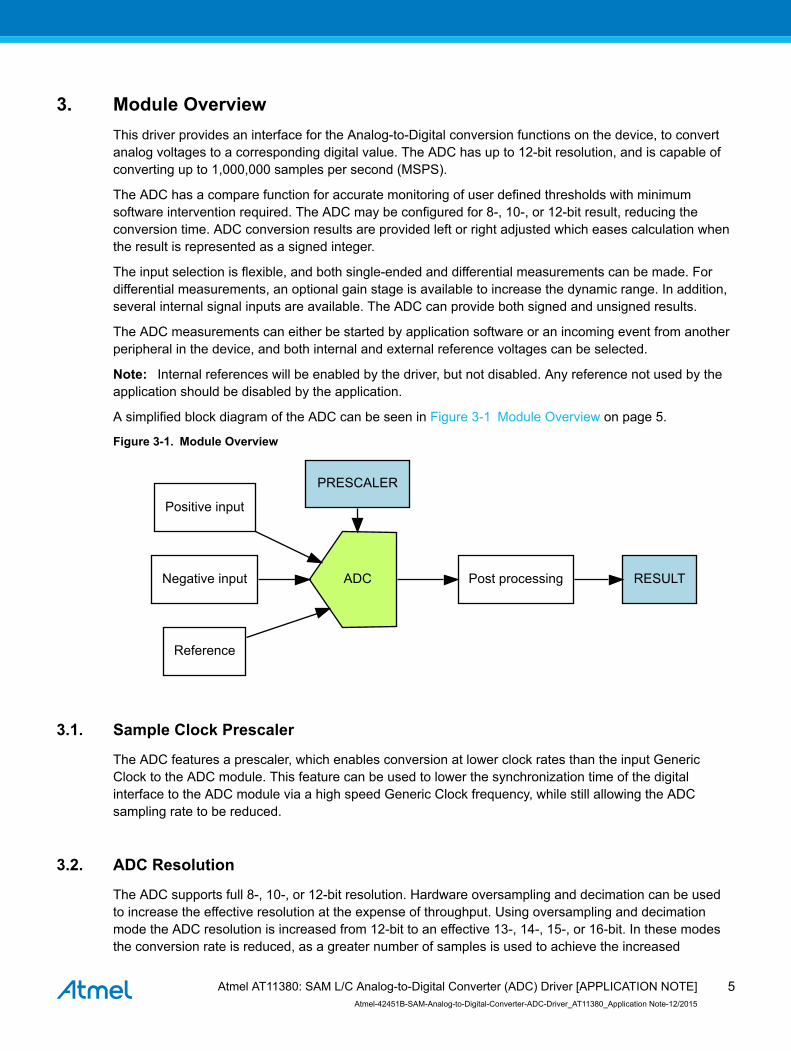
Type Name Description
enum adc_positive_input positive_input Positive MUX input
uint32_t positive_input_sequence_mask_enable Positive input enabled mask forconversion sequence Thesequence start from the lowestinput and go to the next enabledinput automatically when theconversion is done If no bits areset the sequence is disabled
enum adc_reference reference Voltage reference
bool reference_compensation_enable Enables reference buffer offsetcompensation if true This willincrease the accuracy of the gainstage but decreases the inputimpedance therefore the startuptime of the reference must beincreased
enum adc_resolution resolution Result resolution
bool run_in_standby ADC run in standby control
uint8_t sample_length This value (0-63) control the ADCsampling time in number of halfADC prescaled clock cycles(depends of ADC_PRESCALERvalue) thus controlling the ADCinput impedance Sampling time isset according to the formulaSample time = (sample_length+1) (ADCclk 2)
bool sampling_time_compensation_enable Enables sampling period offsetcompensation if true
struct adc_window_config window Window monitor configurationstructure
722 Struct adc_correction_config
Gain and offset correction configuration structure Part of the adc_config struct and will be initialized by adc_get_config_defaults
Atmel AT11380 SAM LC Analog-to-Digital Converter (ADC) Driver [APPLICATION NOTE]Atmel-42451B-SAM-Analog-to-Digital-Converter-ADC-Driver_AT11380_Application Note-122015
13
Table 7-2 Members
Type Name Description
bool correction_enable Enables correction for gain and offset based on values of gain_correctionand offset_correction if set to true
uint16_t gain_correction This value defines how the ADC conversion result is compensated for gainerror before written to the result register This is a fractional value 1-bitinteger plus an 11-bit fraction therefore 12 lt= gain_correction lt 2 Validgain_correction values ranges from 0b010000000000 to0b111111111111
int16_t offset_correction This value defines how the ADC conversion result is compensated foroffset error before written to the result register This is a 12-bit value intwos complement format
723 Struct adc_events
Event flags for the ADC module This is used to enable and disable events via adc_enable_events() and adc_disable_events()
Table 7-3 Members
Type Name Description
bool generate_event_on_conversion_done Enable event generation on conversion done
bool generate_event_on_window_monitor Enable event generation on window monitor
724 Struct adc_module
ADC software instance structure used to retain software state information of an associated hardwaremodule instance
Note The fields of this structure should not be altered by the user application they are reserved formodule-internal use only
725 Struct adc_window_config
Window monitor configuration structure
Table 7-4 Members
Type Name Description
int32_t window_lower_value Lower window value
enum adc_window_mode window_mode Selected window mode
int32_t window_upper_value Upper window value
73 Macro Definitions
731 Module Status Flags
ADC status flags returned by adc_get_status() and cleared by adc_clear_status()
Atmel AT11380 SAM LC Analog-to-Digital Converter (ADC) Driver [APPLICATION NOTE]Atmel-42451B-SAM-Analog-to-Digital-Converter-ADC-Driver_AT11380_Application Note-122015
14
7311 Macro ADC_STATUS_RESULT_READY
define ADC_STATUS_RESULT_READY
ADC result ready
7312 Macro ADC_STATUS_WINDOW
define ADC_STATUS_WINDOW
Window monitor match
7313 Macro ADC_STATUS_OVERRUN
define ADC_STATUS_OVERRUN
ADC result overwritten before read
732 Macro FEATURE_ADC_SUPPORT_MASTER_SLAVE
define FEATURE_ADC_SUPPORT_MASTER_SLAVE
Output Driver Strength Selection feature support
74 Function Definitions
741 Driver Initialization and Configuration
7411 Function adc_init()
Initializes the ADC
enum status_code adc_init( struct adc_module const module_inst Adc hw struct adc_config config)
Initializes the ADC device struct and the hardware module based on the given configuration struct values
Table 7-5 Parameters
Data direction Parameter name Description
[out] module_inst Pointer to the ADC software instance struct
[in] hw Pointer to the ADC module instance
[in] config Pointer to the configuration struct
ReturnsStatus of the initialization procedure
Atmel AT11380 SAM LC Analog-to-Digital Converter (ADC) Driver [APPLICATION NOTE]Atmel-42451B-SAM-Analog-to-Digital-Converter-ADC-Driver_AT11380_Application Note-122015
15
Table 7-6 Return Values
Return value Description
STATUS_OK The initialization was successful
STATUS_ERR_INVALID_ARG Invalid argument(s) were provided
STATUS_BUSY The module is busy with a reset operation
STATUS_ERR_DENIED The module is enabled
7412 Function adc_get_config_defaults()
Initializes an ADC configuration structure to defaults
void adc_get_config_defaults( struct adc_config const config)
Initializes a given ADC configuration struct to a set of known default values This function should be calledon any new instance of the configuration struct before being modified by the user application
The default configuration is as followsbull GCLK generator 0 (GCLK main) clock sourcebull Internal bandgap referencebull Div 2 clock prescalerbull 12-bit resolutionbull Window monitor disabledbull Positive input on ADC PIN 1bull Negative input on Internal groundbull Averaging disabledbull Oversampling disabledbull Right adjust databull Single-ended modebull Free running disabledbull All events (input and generation) disabledbull ADC run in standby disabledbull ADC On demand disabledbull No sampling time compensationbull Disable the positive input sequensebull No reference compensationbull No gainoffset correctionbull No added sampling time
Table 7-7 Parameters
Data direction Parameter name Description
[out] config Pointer to configuration struct to initialize to default values
Atmel AT11380 SAM LC Analog-to-Digital Converter (ADC) Driver [APPLICATION NOTE]Atmel-42451B-SAM-Analog-to-Digital-Converter-ADC-Driver_AT11380_Application Note-122015
16
742 Status Management
7421 Function adc_get_status()
Retrieves the current module status
uint32_t adc_get_status( struct adc_module const module_inst)
Retrieves the status of the module giving overall state information
Table 7-8 Parameters
Data direction Parameter name Description
[in] module_inst Pointer to the ADC software instance struct
ReturnsBitmask of ADC_STATUS_ flags
Table 7-9 Return Values
Return value Description
ADC_STATUS_RESULT_READY ADC result is ready to be read
ADC_STATUS_WINDOW ADC has detected a value inside the set window range
ADC_STATUS_OVERRUN ADC result has overrun
7422 Function adc_clear_status()
Clears a module status flag
void adc_clear_status( struct adc_module const module_inst const uint32_t status_flags)
Clears the given status flag of the module
Table 7-10 Parameters
Data direction Parameter name Description
[in] module_inst Pointer to the ADC software instance struct
[in] status_flags Bitmask of ADC_STATUS_ flags to clear
743 Enable Disable and Reset ADC Module Start Conversion and Read Result
7431 Function adc_enable()
Enables the ADC module
enum status_code adc_enable( struct adc_module const module_inst)
Enables an ADC module that has previously been configured If any internal reference is selected it willbe enabled
Atmel AT11380 SAM LC Analog-to-Digital Converter (ADC) Driver [APPLICATION NOTE]Atmel-42451B-SAM-Analog-to-Digital-Converter-ADC-Driver_AT11380_Application Note-122015
17
Table 7-11 Parameters
Data direction Parameter name Description
[in] module_inst Pointer to the ADC software instance struct
7432 Function adc_disable()
Disables the ADC module
enum status_code adc_disable( struct adc_module const module_inst)
Disables an ADC module that was previously enabled
Table 7-12 Parameters
Data direction Parameter name Description
[in] module_inst Pointer to the ADC software instance struct
7433 Function adc_reset()
Resets the ADC module
enum status_code adc_reset( struct adc_module const module_inst)
Resets an ADC module clearing all module state and registers to their default values
Table 7-13 Parameters
Data direction Parameter name Description
[in] module_inst Pointer to the ADC software instance struct
7434 Function adc_enable_events()
Enables an ADC event input or output
void adc_enable_events( struct adc_module const module_inst struct adc_events const events)
Enables one or more input or output events to or from the ADC module See Struct adc_events for a listof events this module supports
Note Events cannot be altered while the module is enabled
Table 7-14 Parameters
Data direction Parameter name Description
[in] module_inst Software instance for the ADC peripheral
[in] events Struct containing flags of events to enable
Atmel AT11380 SAM LC Analog-to-Digital Converter (ADC) Driver [APPLICATION NOTE]Atmel-42451B-SAM-Analog-to-Digital-Converter-ADC-Driver_AT11380_Application Note-122015
18
7435 Function adc_disable_events()
Disables an ADC event input or output
void adc_disable_events( struct adc_module const module_inst struct adc_events const events)
Disables one or more input or output events to or from the ADC module See Struct adc_events for a listof events this module supports
Note Events cannot be altered while the module is enabled
Table 7-15 Parameters
Data direction Parameter name Description
[in] module_inst Software instance for the ADC peripheral
[in] events Struct containing flags of events to disable
7436 Function adc_start_conversion()
Starts an ADC conversion
void adc_start_conversion( struct adc_module const module_inst)
Starts a new ADC conversion
Table 7-16 Parameters
Data direction Parameter name Description
[in] module_inst Pointer to the ADC software instance struct
7437 Function adc_read()
Reads the ADC result
enum status_code adc_read( struct adc_module const module_inst uint16_t result)
Reads the result from an ADC conversion that was previously started
Table 7-17 Parameters
Data direction Parameter name Description
[in] module_inst Pointer to the ADC software instance struct
[out] result Pointer to store the result value in
ReturnsStatus of the ADC read request
Atmel AT11380 SAM LC Analog-to-Digital Converter (ADC) Driver [APPLICATION NOTE]Atmel-42451B-SAM-Analog-to-Digital-Converter-ADC-Driver_AT11380_Application Note-122015
19
Table 7-18 Return Values
Return value Description
STATUS_OK The result was retrieved successfully
STATUS_BUSY A conversion result was not ready
STATUS_ERR_OVERFLOW The result register has been overwritten by the ADC module before theresult was read by the software
744 Runtime Changes of ADC Module
7441 Function adc_flush()
Flushes the ADC pipeline
void adc_flush( struct adc_module const module_inst)
Flushes the pipeline and restarts the ADC clock on the next peripheral clock edge All conversions inprogress will be lost When flush is complete the module will resume where it left off
Table 7-19 Parameters
Data direction Parameter name Description
[in] module_inst Pointer to the ADC software instance struct
7442 Function adc_set_window_mode()
Sets the ADC window mode
void adc_set_window_mode( struct adc_module const module_inst const enum adc_window_mode window_mode const int16_t window_lower_value const int16_t window_upper_value)
Sets the ADC window mode to a given mode and value range
Table 7-20 Parameters
Data direction Parameter name Description
[in] module_inst Pointer to the ADC software instance struct
[in] window_mode Window monitor mode to set
[in] window_lower_value Lower window monitor threshold value
[in] window_upper_value Upper window monitor threshold value
7443 Function adc_set_positive_input()
Sets positive ADC input pin
void adc_set_positive_input( struct adc_module const module_inst const enum adc_positive_input positive_input)
Atmel AT11380 SAM LC Analog-to-Digital Converter (ADC) Driver [APPLICATION NOTE]Atmel-42451B-SAM-Analog-to-Digital-Converter-ADC-Driver_AT11380_Application Note-122015
20
Sets the positive ADC input pin selection
Table 7-21 Parameters
Data direction Parameter name Description
[in] module_inst Pointer to the ADC software instance struct
[in] positive_input Positive input pin
7444 Function adc_set_negative_input()
Sets negative ADC input pin for differential mode
void adc_set_negative_input( struct adc_module const module_inst const enum adc_negative_input negative_input)
Sets the negative ADC input pin when the ADC is configured in differential mode
Table 7-22 Parameters
Data direction Parameter name Description
[in] module_inst Pointer to the ADC software instance struct
[in] negative_input Negative input pin
745 Enable and Disable Interrupts
7451 Function adc_enable_interrupt()
Enable interrupt
void adc_enable_interrupt( struct adc_module const module_inst enum adc_interrupt_flag interrupt)
Enable the given interrupt request from the ADC module
Table 7-23 Parameters
Data direction Parameter name Description
[in] module_inst Pointer to the ADC software instance struct
[in] interrupt Interrupt to enable
7452 Function adc_disable_interrupt()
Disable interrupt
void adc_disable_interrupt( struct adc_module const module_inst enum adc_interrupt_flag interrupt)
Disable the given interrupt request from the ADC module
Atmel AT11380 SAM LC Analog-to-Digital Converter (ADC) Driver [APPLICATION NOTE]Atmel-42451B-SAM-Analog-to-Digital-Converter-ADC-Driver_AT11380_Application Note-122015
21
Table 7-24 Parameters
Data direction Parameter name Description
[in] module_inst Pointer to the ADC software instance struct
[in] interrupt Interrupt to disable
746 Callback Management
7461 Function adc_register_callback()
Registers a callback
void adc_register_callback( struct adc_module const module adc_callback_t callback_func enum adc_callback callback_type)
Registers a callback function which is implemented by the user
Note The callback must be enabled for the interrupt handler to call it when the condition for the callbackis met
Table 7-25 Parameters
Data direction Parameter name Description
[in] module Pointer to ADC software instance struct
[in] callback_func Pointer to callback function
[in] callback_type Callback type given by an enum
7462 Function adc_unregister_callback()
Unregisters a callback
void adc_unregister_callback( struct adc_module module enum adc_callback callback_type)
Unregisters a callback function which is implemented by the user
Table 7-26 Parameters
Data direction Parameter name Description
[in] module Pointer to ADC software instance struct
[in] callback_type Callback type given by an enum
7463 Function adc_enable_callback()
Enables callback
void adc_enable_callback( struct adc_module const module enum adc_callback callback_type)
Atmel AT11380 SAM LC Analog-to-Digital Converter (ADC) Driver [APPLICATION NOTE]Atmel-42451B-SAM-Analog-to-Digital-Converter-ADC-Driver_AT11380_Application Note-122015
22
Enables the callback function registered by adc_register_callback The callback function will be calledfrom the interrupt handler when the conditions for the callback type are met
Table 7-27 Parameters
Data direction Parameter name Description
[in] module Pointer to ADC software instance struct
[in] callback_type Callback type given by an enum
ReturnsStatus of the operation
Table 7-28 Return Values
Return value Description
STATUS_OK If operation was completed
STATUS_ERR_INVALID If operation was not completed due to invalid callback_type
7464 Function adc_disable_callback()
Disables callback
void adc_disable_callback( struct adc_module const module enum adc_callback callback_type)
Disables the callback function registered by the adc_register_callback
Table 7-29 Parameters
Data direction Parameter name Description
[in] module Pointer to ADC software instance struct
[in] callback_type Callback type given by an enum
ReturnsStatus of the operation
Table 7-30 Return Values
Return value Description
STATUS_OK If operation was completed
STATUS_ERR_INVALID If operation was not completed due to invalid callback_type
747 Job Management
7471 Function adc_read_buffer_job()
Read multiple samples from ADC
enum status_code adc_read_buffer_job( struct adc_module const module_inst
Atmel AT11380 SAM LC Analog-to-Digital Converter (ADC) Driver [APPLICATION NOTE]Atmel-42451B-SAM-Analog-to-Digital-Converter-ADC-Driver_AT11380_Application Note-122015
23
uint16_t buffer uint16_t samples)
Read samples from the ADC into the buffer If there is no hardware trigger defined (event action) thedriver will retrigger the ADC conversion whenever a conversion is complete until samples has beenacquired To avoid jitter in the sampling frequency using an event trigger is advised
Table 7-31 Parameters
Data direction Parameter name Description
[in] module_inst Pointer to the ADC software instance struct
[in] samples Number of samples to acquire
[out] buffer Buffer to store the ADC samples
ReturnsStatus of the job start
Table 7-32 Return Values
Return value Description
STATUS_OK The conversion job was started successfully and is in progress
STATUS_BUSY The ADC is already busy with another job
7472 Function adc_get_job_status()
Gets the status of a job
enum status_code adc_get_job_status( struct adc_module module_inst enum adc_job_type type)
Gets the status of an ongoing or the last job
Table 7-33 Parameters
Data direction Parameter name Description
[in] module_inst Pointer to the ADC software instance struct
[in] type Type of to get status
ReturnsStatus of the job
7473 Function adc_abort_job()
Aborts an ongoing job
void adc_abort_job( struct adc_module module_inst enum adc_job_type type)
Aborts an ongoing job
Atmel AT11380 SAM LC Analog-to-Digital Converter (ADC) Driver [APPLICATION NOTE]Atmel-42451B-SAM-Analog-to-Digital-Converter-ADC-Driver_AT11380_Application Note-122015
24
Table 7-34 Parameters
Data direction Parameter name Description
[in] module_inst Pointer to the ADC software instance struct
[in] type Type of job to abort
748 Positive Input Sequence
7481 Function adc_enable_positive_input_sequence()
Enable positive input sequence mask for conversion
void adc_enable_positive_input_sequence( struct adc_module const module_inst uint32_t positive_input_sequence_mask_enable)
The sequence start from the lowest input and go to the next enabled input automatically when theconversion is done If no bits are set the sequence is disabled
Table 7-35 Parameters
Data direction Parameter name Description
[in] module_inst Pointer to the ADC software instance struct
[in] eanble_seq_mask Sequence mask
7482 Function adc_disable_positive_input_sequence()
Disable positive input in the sequence
void adc_disable_positive_input_sequence( struct adc_module const module_inst)
Disable positive input in the sequence
Table 7-36 Parameters
Data direction Parameter name Description
[in] module_inst Pointer to the ADC software instance struct
7483 Function adc_get_sequence_status()
Get ADC sequence status
void adc_get_sequence_status( struct adc_module const module_inst bool is_sequence_busy uint8_t sequence_state)
Check if a sequence is done and get last conversion done in the sequence
Atmel AT11380 SAM LC Analog-to-Digital Converter (ADC) Driver [APPLICATION NOTE]Atmel-42451B-SAM-Analog-to-Digital-Converter-ADC-Driver_AT11380_Application Note-122015
25
Table 7-37 Parameters
Data direction Parameter name Description
[in] module_inst Pointer to the ADC software instance struct
[out] is_sequence_busy Sequence busy status
[out] sequence_state This value identifies the last conversion done in the sequence
749 Function adc_set_master_slave_mode()
Set ADC master and slave mode
void adc_set_master_slave_mode( struct adc_module const master_inst struct adc_module const slave_inst enum adc_dual_mode_trigger_selection dualsel)
Enable ADC module Master-Slave Operation and select dual mode trigger
Table 7-38 Parameters
Data direction Parameter name Description
[in] master_inst Pointer to the master ADC software instance struct
[in] slave_inst Pointer to the slave ADC software instance struct
[in] dualsel Dual mode trigger selection
75 Enumeration Definitions
751 Enum adc_accumulate_samples
Enum for the possible numbers of ADC samples to accumulate This setting is only used when the ADC_RESOLUTION_CUSTOM resolution setting is used
Table 7-39 Members
Enum value Description
ADC_ACCUMULATE_DISABLE No averaging
ADC_ACCUMULATE_SAMPLES_2 Average 2 samples
ADC_ACCUMULATE_SAMPLES_4 Average 4 samples
ADC_ACCUMULATE_SAMPLES_8 Average 8 samples
ADC_ACCUMULATE_SAMPLES_16 Average 16 samples
ADC_ACCUMULATE_SAMPLES_32 Average 32 samples
ADC_ACCUMULATE_SAMPLES_64 Average 64 samples
ADC_ACCUMULATE_SAMPLES_128 Average 128 samples
Atmel AT11380 SAM LC Analog-to-Digital Converter (ADC) Driver [APPLICATION NOTE]Atmel-42451B-SAM-Analog-to-Digital-Converter-ADC-Driver_AT11380_Application Note-122015
26
Enum value Description
ADC_ACCUMULATE_SAMPLES_256 Average 256 samples
ADC_ACCUMULATE_SAMPLES_512 Average 512 samples
ADC_ACCUMULATE_SAMPLES_1024 Average 1024 samples
752 Enum adc_callback
Callback types for ADC callback driver
Table 7-40 Members
Enum value Description
ADC_CALLBACK_READ_BUFFER Callback for buffer received
ADC_CALLBACK_WINDOW Callback when window is hit
ADC_CALLBACK_ERROR Callback for error
753 Enum adc_clock_prescaler
Enum for the possible clock prescaler values for the ADC
Table 7-41 Members
Enum value Description
ADC_CLOCK_PRESCALER_DIV2 ADC clock division factor 2
ADC_CLOCK_PRESCALER_DIV4 ADC clock division factor 4
ADC_CLOCK_PRESCALER_DIV8 ADC clock division factor 8
ADC_CLOCK_PRESCALER_DIV16 ADC clock division factor 16
ADC_CLOCK_PRESCALER_DIV32 ADC clock division factor 32
ADC_CLOCK_PRESCALER_DIV64 ADC clock division factor 64
ADC_CLOCK_PRESCALER_DIV128 ADC clock division factor 128
ADC_CLOCK_PRESCALER_DIV256 ADC clock division factor 256
754 Enum adc_divide_result
Enum for the possible division factors to use when accumulating multiple samples To keep the sameresolution for the averaged result and the actual input value the division factor must be equal to thenumber of samples accumulated This setting is only used when the ADC_RESOLUTION_CUSTOMresolution setting is used
Atmel AT11380 SAM LC Analog-to-Digital Converter (ADC) Driver [APPLICATION NOTE]Atmel-42451B-SAM-Analog-to-Digital-Converter-ADC-Driver_AT11380_Application Note-122015
27
Table 7-42 Members
Enum value Description
ADC_DIVIDE_RESULT_DISABLE Dont divide result register after accumulation
ADC_DIVIDE_RESULT_2 Divide result register by 2 after accumulation
ADC_DIVIDE_RESULT_4 Divide result register by 4 after accumulation
ADC_DIVIDE_RESULT_8 Divide result register by 8 after accumulation
ADC_DIVIDE_RESULT_16 Divide result register by 16 after accumulation
ADC_DIVIDE_RESULT_32 Divide result register by 32 after accumulation
ADC_DIVIDE_RESULT_64 Divide result register by 64 after accumulation
ADC_DIVIDE_RESULT_128 Divide result register by 128 after accumulation
755 Enum adc_dual_mode_trigger_selection
Enum for the trigger selection in dual mode
Table 7-43 Members
Enum value Description
ADC_DUAL_MODE_BOTH Start event or software trigger will start a conversion on both ADCs
ADC_DUAL_MODE_INTERLEAVE START event or software trigger will alternatingly start a conversionon ADC0 and ADC1
756 Enum adc_event_action
Enum for the possible actions to take on an incoming event
Table 7-44 Members
Enum value Description
ADC_EVENT_ACTION_DISABLED Event action disabled
ADC_EVENT_ACTION_FLUSH_START_CONV Flush ADC and start conversion
ADC_EVENT_ACTION_START_CONV Start conversion
757 Enum adc_interrupt_flag
Enum for the possible ADC interrupt flags
Atmel AT11380 SAM LC Analog-to-Digital Converter (ADC) Driver [APPLICATION NOTE]Atmel-42451B-SAM-Analog-to-Digital-Converter-ADC-Driver_AT11380_Application Note-122015
28
Table 7-45 Members
Enum value Description
ADC_INTERRUPT_RESULT_READY ADC result ready
ADC_INTERRUPT_WINDOW Window monitor match
ADC_INTERRUPT_OVERRUN ADC result overwritten before read
758 Enum adc_job_type
Enum for the possible types of ADC asynchronous jobs that may be issued to the driver
Table 7-46 Members
Enum value Description
ADC_JOB_READ_BUFFER Asynchronous ADC read into a user provided buffer
759 Enum adc_negative_input
Enum for the possible negative MUX input selections for the ADC
Table 7-47 Members
Enum value Description
ADC_NEGATIVE_INPUT_PIN0 ADC0 pin
ADC_NEGATIVE_INPUT_PIN1 ADC1 pin
ADC_NEGATIVE_INPUT_PIN2 ADC2 pin
ADC_NEGATIVE_INPUT_PIN3 ADC3 pin
ADC_NEGATIVE_INPUT_PIN4 ADC4 pin
ADC_NEGATIVE_INPUT_PIN5 ADC5 pin
ADC_NEGATIVE_INPUT_PIN6 ADC6 pin
ADC_NEGATIVE_INPUT_PIN7 ADC7 pin
ADC_NEGATIVE_INPUT_GND Internal ground
7510 Enum adc_oversampling_and_decimation
Enum for the possible numbers of bits resolution can be increased by when using oversampling anddecimation
Table 7-48 Members
Enum value Description
ADC_OVERSAMPLING_AND_DECIMATION_DISABLE Dont use oversampling and decimation mode
ADC_OVERSAMPLING_AND_DECIMATION_1BIT 1-bit resolution increase
Atmel AT11380 SAM LC Analog-to-Digital Converter (ADC) Driver [APPLICATION NOTE]Atmel-42451B-SAM-Analog-to-Digital-Converter-ADC-Driver_AT11380_Application Note-122015
29
Enum value Description
ADC_OVERSAMPLING_AND_DECIMATION_2BIT 2-bit resolution increase
ADC_OVERSAMPLING_AND_DECIMATION_3BIT 3-bit resolution increase
ADC_OVERSAMPLING_AND_DECIMATION_4BIT 4-bit resolution increase
7511 Enum adc_positive_input
Enum for the possible positive MUX input selections for the ADC
Table 7-49 Members
Enum value Description
ADC_POSITIVE_INPUT_PIN0 ADC0 pin
ADC_POSITIVE_INPUT_PIN1 ADC1 pin
ADC_POSITIVE_INPUT_PIN2 ADC2 pin
ADC_POSITIVE_INPUT_PIN3 ADC3 pin
ADC_POSITIVE_INPUT_PIN4 ADC4 pin
ADC_POSITIVE_INPUT_PIN5 ADC5 pin
ADC_POSITIVE_INPUT_PIN6 ADC6 pin
ADC_POSITIVE_INPUT_PIN7 ADC7 pin
ADC_POSITIVE_INPUT_PIN8 ADC8 pin
ADC_POSITIVE_INPUT_PIN9 ADC9 pin
ADC_POSITIVE_INPUT_PIN10 ADC10 pin
ADC_POSITIVE_INPUT_PIN11 ADC11 pin
ADC_POSITIVE_INPUT_PIN12 ADC12 pin
ADC_POSITIVE_INPUT_PIN13 ADC13 pin
ADC_POSITIVE_INPUT_PIN14 ADC14 pin
ADC_POSITIVE_INPUT_PIN15 ADC15 pin
ADC_POSITIVE_INPUT_PIN16 ADC16 pin
ADC_POSITIVE_INPUT_PIN17 ADC17 pin
ADC_POSITIVE_INPUT_PIN18 ADC18 pin
ADC_POSITIVE_INPUT_PIN19 ADC19 pin
ADC_POSITIVE_INPUT_PIN20 ADC20 pin
Atmel AT11380 SAM LC Analog-to-Digital Converter (ADC) Driver [APPLICATION NOTE]Atmel-42451B-SAM-Analog-to-Digital-Converter-ADC-Driver_AT11380_Application Note-122015
30
Enum value Description
ADC_POSITIVE_INPUT_PIN21 ADC21 pin
ADC_POSITIVE_INPUT_PIN22 ADC22 pin
ADC_POSITIVE_INPUT_PIN23 ADC23 pin
ADC_POSITIVE_INPUT_TEMP Temperature reference
ADC_POSITIVE_INPUT_BANDGAP Bandgap voltage
ADC_POSITIVE_INPUT_SCALEDCOREVCC 14 scaled core supply
ADC_POSITIVE_INPUT_SCALEDIOVCC 14 scaled IO supply
ADC_POSITIVE_INPUT_DAC DAC input
7512 Enum adc_reference
Enum for the possible reference voltages for the ADC
Table 7-50 Members
Enum value Description
ADC_REFERENCE_INTREF Internal Bandgap Reference
ADC_REFERENCE_INTVCC0 1148VCC reference
ADC_REFERENCE_INTVCC1 12VCC (only for internal VCC gt 21V)
ADC_REFERENCE_AREFA External reference A
ADC_REFERENCE_INTVCC2 VDDANA
7513 Enum adc_resolution
Enum for the possible resolution values for the ADC
Table 7-51 Members
Enum value Description
ADC_RESOLUTION_12BIT ADC 12-bit resolution
ADC_RESOLUTION_16BIT ADC 16-bit resolution using oversampling and decimation
ADC_RESOLUTION_10BIT ADC 10-bit resolution
ADC_RESOLUTION_8BIT ADC 8-bit resolution
ADC_RESOLUTION_13BIT ADC 13-bit resolution using oversampling and decimation
ADC_RESOLUTION_14BIT ADC 14-bit resolution using oversampling and decimation
Atmel AT11380 SAM LC Analog-to-Digital Converter (ADC) Driver [APPLICATION NOTE]Atmel-42451B-SAM-Analog-to-Digital-Converter-ADC-Driver_AT11380_Application Note-122015
31
Enum value Description
ADC_RESOLUTION_15BIT ADC 15-bit resolution using oversampling and decimation
ADC_RESOLUTION_CUSTOM ADC 16-bit result register for use with averaging When using thismode the ADC result register will be set to 16-bit wide and the numberof samples to accumulate and the division factor is configured by the adc_configaccumulate_samples and adc_configdivide_resultmembers in the configuration struct
7514 Enum adc_window_mode
Enum for the possible window monitor modes for the ADC
Table 7-52 Members
Enum value Description
ADC_WINDOW_MODE_DISABLE No window mode
ADC_WINDOW_MODE_ABOVE_LOWER RESULT gt WINLT
ADC_WINDOW_MODE_BELOW_UPPER RESULT lt WINUT
ADC_WINDOW_MODE_BETWEEN WINLT lt RESULT lt WINUT
ADC_WINDOW_MODE_BETWEEN_INVERTED (WINLT lt RESULT lt WINUT)
Atmel AT11380 SAM LC Analog-to-Digital Converter (ADC) Driver [APPLICATION NOTE]Atmel-42451B-SAM-Analog-to-Digital-Converter-ADC-Driver_AT11380_Application Note-122015
32
8 Extra Information for ADC Driver
81 AcronymsBelow is a table listing the acronyms used in this module along with their intended meanings
Acronym Description
ADC Analog-to-Digital Converter
DAC Digital-to-Analog Converter
LSB Least Significant Bit
MSB Most Significant Bit
DMA Direct Memory Access
82 DependenciesThis driver has the following dependencies
bull System Pin Multiplexer Driver
83 ErrataThere are no errata related to this driver
84 Module HistoryAn overview of the module history is presented in the table below with details on the enhancements andfixes made to the module since its first release The current version of this corresponds to the newestversion in the table
Changelog
Initial Release
Atmel AT11380 SAM LC Analog-to-Digital Converter (ADC) Driver [APPLICATION NOTE]Atmel-42451B-SAM-Analog-to-Digital-Converter-ADC-Driver_AT11380_Application Note-122015
33
9 Examples for ADC DriverThis is a list of the available Quick Start guides (QSGs) and example applications for SAM Analog-to-Digital Converter (ADC) Driver QSGs are simple examples with step-by-step instructions to configureand use this driver in a selection of use cases Note that a QSG can be compiled as a standaloneapplication or be added to the user application
bull Quick Start Guide for ADC - Basicbull Quick Start Guide for ADC - Callbackbull Quick Start Guide for Using DMA with ADCDAC
91 Quick Start Guide for ADC - BasicIn this use case the ADC will be configured with the following settings
bull 1V from internal bandgap referencebull Div 4 clock prescalerbull 12-bit resolutionbull Window monitor disabledbull No gainbull Positive input on ADC PIN x (depend on default configuration)bull Negative input to GND (single ended)bull Averaging disabledbull Oversampling disabledbull Right adjust databull Single-ended modebull Free running disabledbull All events (input and generation) disabledbull Sleep operation disabledbull No reference compensationbull No gainoffset correctionbull No added sampling timebull Pin scan mode disabled
911 Setup
9111 Prerequisites
There are no special setup requirements for this use-case
9112 Code
Add to the main application source file outside of any functionsstruct adc_module adc_instance
Copy-paste the following setup code to your user applicationvoid configure_adc(void) struct adc_config config_adc adc_get_config_defaults(ampconfig_adc)
Atmel AT11380 SAM LC Analog-to-Digital Converter (ADC) Driver [APPLICATION NOTE]Atmel-42451B-SAM-Analog-to-Digital-Converter-ADC-Driver_AT11380_Application Note-122015
34
if (SAMC21) adc_init(ampadc_instance ADC1 ampconfig_adc)else adc_init(ampadc_instance ADC ampconfig_adc)endif
adc_enable(ampadc_instance)
Add to user application initialization (typically the start of main())
configure_adc()
9113 Workflow
1 Create a module software instance structure for the ADC module to store the ADC driver statewhile in usestruct adc_module adc_instance
Note This should never go out of scope as long as the module is in use In most cases thisshould be global
2 Configure the ADC module1 Create an ADC module configuration struct which can be filled out to adjust the configuration
of a physical ADC peripheralstruct adc_config config_adc
2 Initialize the ADC configuration struct with the modules default valuesadc_get_config_defaults(ampconfig_adc)
Note This should always be performed before using the configuration struct to ensure thatall values are initialized to known default settings
3 Set ADC configurationsif (SAMC21) adc_init(ampadc_instance ADC1 ampconfig_adc)else adc_init(ampadc_instance ADC ampconfig_adc)endif
4 Enable the ADC module so that conversions can be madeadc_enable(ampadc_instance)
912 Use Case
9121 Code
Copy-paste the following code to your user applicationadc_start_conversion(ampadc_instance)uint16_t result
do Wait for conversion to be done and read out result while (adc_read(ampadc_instance ampresult) == STATUS_BUSY)while (1)
Atmel AT11380 SAM LC Analog-to-Digital Converter (ADC) Driver [APPLICATION NOTE]Atmel-42451B-SAM-Analog-to-Digital-Converter-ADC-Driver_AT11380_Application Note-122015
35
Infinite loop
9122 Workflow
1 Start conversionadc_start_conversion(ampadc_instance)
2 Wait until conversion is done and read resultuint16_t result
do Wait for conversion to be done and read out result while (adc_read(ampadc_instance ampresult) == STATUS_BUSY)
3 Enter an infinite loop once the conversion is completewhile (1) Infinite loop
92 Quick Start Guide for ADC - CallbackIn this use case the ADC will convert 128 samples using interrupt driven conversion When all sampleshave been sampled a callback will be called that signals the main application that conversion iscomplete
The ADC will be set up as followsbull VCC 2 as referencebull Div 8 clock prescalerbull 12-bit resolutionbull Window monitor disabledbull 12 gainbull Positive input on ADC PIN 0bull Negative input to GND (single ended)bull Averaging disabledbull Oversampling disabledbull Right adjust databull Single-ended modebull Free running disabledbull All events (input and generation) disabledbull Sleep operation disabledbull No reference compensationbull No gainoffset correctionbull No added sampling timebull Pin scan mode disabled
921 Setup
9211 Prerequisites
There are no special setup requirements for this use-case
Atmel AT11380 SAM LC Analog-to-Digital Converter (ADC) Driver [APPLICATION NOTE]Atmel-42451B-SAM-Analog-to-Digital-Converter-ADC-Driver_AT11380_Application Note-122015
36
9212 Code
Add to the main application source file outside of any functionsstruct adc_module adc_instance
define ADC_SAMPLES 128uint16_t adc_result_buffer[ADC_SAMPLES]
Callback functionvolatile bool adc_read_done = false
void adc_complete_callback( struct adc_module const module) adc_read_done = true
Copy-paste the following setup code to your user applicationvoid configure_adc(void) struct adc_config config_adc adc_get_config_defaults(ampconfig_adc)if (SAML21) ampamp (SAML22) ampamp (SAMC21) config_adcgain_factor = ADC_GAIN_FACTOR_DIV2endif config_adcclock_prescaler = ADC_CLOCK_PRESCALER_DIV8 config_adcreference = ADC_REFERENCE_INTVCC1if (SAMC21) config_adcpositive_input = ADC_POSITIVE_INPUT_PIN5else config_adcpositive_input = ADC_POSITIVE_INPUT_PIN6endif config_adcresolution = ADC_RESOLUTION_12BITif (SAMC21) adc_init(ampadc_instance ADC1 ampconfig_adc)else adc_init(ampadc_instance ADC ampconfig_adc)endif
adc_enable(ampadc_instance)
void configure_adc_callbacks(void) adc_register_callback(ampadc_instance adc_complete_callback ADC_CALLBACK_READ_BUFFER) adc_enable_callback(ampadc_instance ADC_CALLBACK_READ_BUFFER)
Add to user application initialization (typically the start of main())
configure_adc()configure_adc_callbacks()
Atmel AT11380 SAM LC Analog-to-Digital Converter (ADC) Driver [APPLICATION NOTE]Atmel-42451B-SAM-Analog-to-Digital-Converter-ADC-Driver_AT11380_Application Note-122015
37
9213 Workflow
1 Create a module software instance structure for the ADC module to store the ADC driver statewhile in usestruct adc_module adc_instance
Note This should never go out of scope as long as the module is in use In most cases thisshould be global
2 Create a buffer for the ADC samples to be stored in by the driver asynchronouslydefine ADC_SAMPLES 128uint16_t adc_result_buffer[ADC_SAMPLES]
3 Create a callback function that will be called each time the ADC completes an asynchronous readjobvolatile bool adc_read_done = false
void adc_complete_callback( struct adc_module const module) adc_read_done = true
4 Configure the ADC module1 Create an ADC module configuration struct which can be filled out to adjust the configuration
of a physical ADC peripheralstruct adc_config config_adc
2 Initialize the ADC configuration struct with the modules default valuesadc_get_config_defaults(ampconfig_adc)
Note This should always be performed before using the configuration struct to ensure thatall values are initialized to known default settings
3 Change the ADC module configuration to suit the applicationif (SAML21) ampamp (SAML22) ampamp (SAMC21) config_adcgain_factor = ADC_GAIN_FACTOR_DIV2endif config_adcclock_prescaler = ADC_CLOCK_PRESCALER_DIV8 config_adcreference = ADC_REFERENCE_INTVCC1if (SAMC21) config_adcpositive_input = ADC_POSITIVE_INPUT_PIN5else config_adcpositive_input = ADC_POSITIVE_INPUT_PIN6endif config_adcresolution = ADC_RESOLUTION_12BIT
4 Set ADC configurationsif (SAMC21) adc_init(ampadc_instance ADC1 ampconfig_adc)else adc_init(ampadc_instance ADC ampconfig_adc)endif
5 Enable the ADC module so that conversions can be madeadc_enable(ampadc_instance)
Atmel AT11380 SAM LC Analog-to-Digital Converter (ADC) Driver [APPLICATION NOTE]Atmel-42451B-SAM-Analog-to-Digital-Converter-ADC-Driver_AT11380_Application Note-122015
38
5 Register and enable the ADC Read Buffer Complete callback handler1 Register the user-provided Read Buffer Complete callback function with the driver so that it
will be run when an asynchronous buffer read job completesadc_register_callback(ampadc_instance adc_complete_callback ADC_CALLBACK_READ_BUFFER)
2 Enable the Read Buffer Complete callback so that it will generate callbacksadc_enable_callback(ampadc_instance ADC_CALLBACK_READ_BUFFER)
922 Use Case
9221 Code
Copy-paste the following code to your user applicationsystem_interrupt_enable_global()adc_read_buffer_job(ampadc_instance adc_result_buffer ADC_SAMPLES)while (adc_read_done == false) Wait for asynchronous ADC read to complete while (1) Infinite loop
9222 Workflow
1 Enable global interrupts so that callbacks can be generated by the driversystem_interrupt_enable_global()
2 Start an asynchronous ADC conversion to store ADC samples into the global buffer and generatea callback when completeadc_read_buffer_job(ampadc_instance adc_result_buffer ADC_SAMPLES)
3 Wait until the asynchronous conversion is completewhile (adc_read_done == false) Wait for asynchronous ADC read to complete
4 Enter an infinite loop once the conversion is completewhile (1) Infinite loop
93 Quick Start Guide for Using DMA with ADCDAC
The supported board listbull SAM D21 Xplained Probull SAM D11 Xplained Probull SAM L21 Xplained Probull SAM DA1 Xplained Pro
Atmel AT11380 SAM LC Analog-to-Digital Converter (ADC) Driver [APPLICATION NOTE]Atmel-42451B-SAM-Analog-to-Digital-Converter-ADC-Driver_AT11380_Application Note-122015
39
bull SAM C21 Xplained Pro
This quick start will convert an analog input signal from AIN4 and output the converted value to DAC onPA2 The data between ADC and DAC with be transferred through DMA instead of a CPU intervene
The ADC will be configured with the following settingsbull 12 VDDANAbull Div 16 clock prescalerbull 10-bit resolutionbull Window monitor disabledbull No gainbull Positive input on ADC AIN4bull Averaging disabledbull Oversampling disabledbull Right adjust databull Single-ended modebull Free running enablebull All events (input and generation) disabledbull Sleep operation disabledbull No reference compensationbull No gainoffset correctionbull No added sampling timebull Pin scan mode disabled
The DAC will be configured with the following settingsbull Analog VCC as referencebull Internal output disabledbull Drive the DAC output to PA2bull Right adjust databull The output buffer is disabled when the chip enters STANDBY sleep mode
The DMA will be configured with the following settingsbull Move data from peripheral to peripheralbull Using ADC result ready triggerbull Using DMA priority level 0bull Beat transfer will be triggered on each triggerbull Loopback descriptor for DAC conversion
931 Setup
9311 Prerequisites
There are no special setup requirements for this use-case
Atmel AT11380 SAM LC Analog-to-Digital Converter (ADC) Driver [APPLICATION NOTE]Atmel-42451B-SAM-Analog-to-Digital-Converter-ADC-Driver_AT11380_Application Note-122015
40
9312 Code
Add to the main application source file outside of any functionsstruct dac_module dac_instance
struct adc_module adc_instance
struct dma_resource example_resource
COMPILER_ALIGNED(16)DmacDescriptor example_descriptor SECTION_DMAC_DESCRIPTOR
Copy-paste the following setup code to your user applicationvoid configure_adc(void) struct adc_config config_adc adc_get_config_defaults(ampconfig_adc)if (SAML21)if (SAMC21) config_adcgain_factor = ADC_GAIN_FACTOR_DIV2endif config_adcresolution = ADC_RESOLUTION_10BITendif config_adcclock_prescaler = ADC_CLOCK_PRESCALER_DIV16 config_adcreference = ADC_REFERENCE_INTVCC1 config_adcpositive_input = ADC_POSITIVE_INPUT_PIN4 config_adcfreerunning = true config_adcleft_adjust = falseif (SAMC21) adc_init(ampadc_instance ADC1 ampconfig_adc)else adc_init(ampadc_instance ADC ampconfig_adc)endif
adc_enable(ampadc_instance)void configure_dac(void) struct dac_config config_dac dac_get_config_defaults(ampconfig_dac)if (SAML21) config_dacreference = DAC_REFERENCE_INTREFelse config_dacreference = DAC_REFERENCE_AVCCendif
dac_init(ampdac_instance DAC ampconfig_dac)
void configure_dac_channel(void) struct dac_chan_config config_dac_chan
Atmel AT11380 SAM LC Analog-to-Digital Converter (ADC) Driver [APPLICATION NOTE]Atmel-42451B-SAM-Analog-to-Digital-Converter-ADC-Driver_AT11380_Application Note-122015
41
dac_chan_get_config_defaults(ampconfig_dac_chan) dac_chan_set_config(ampdac_instance DAC_CHANNEL_0 ampconfig_dac_chan) dac_chan_enable(ampdac_instance DAC_CHANNEL_0)void configure_dma_resource(struct dma_resource resource) struct dma_resource_config config dma_get_config_defaults(ampconfig)if (SAMC21) configperipheral_trigger = ADC1_DMAC_ID_RESRDYelse configperipheral_trigger = ADC_DMAC_ID_RESRDYendif configtrigger_action = DMA_TRIGGER_ACTON_BEAT dma_allocate(resource ampconfig)void setup_transfer_descriptor(DmacDescriptor descriptor) struct dma_descriptor_config descriptor_config dma_descriptor_get_config_defaults(ampdescriptor_config) descriptor_configbeat_size = DMA_BEAT_SIZE_HWORD descriptor_configdst_increment_enable = false descriptor_configsrc_increment_enable = false descriptor_configblock_transfer_count = 1000 descriptor_configsource_address = (uint32_t)(ampadc_instancehw-gtRESULTreg)if (SAML21) descriptor_configdestination_address = (uint32_t)(ampdac_instancehw-gtDATA[DAC_CHANNEL_0]reg)else descriptor_configdestination_address = (uint32_t)(ampdac_instancehw-gtDATAreg)endif descriptor_confignext_descriptor_address = (uint32_t)descriptor dma_descriptor_create(descriptor ampdescriptor_config)
Add to user application initialization (typically the start of main())
configure_adc()configure_dac()configure_dac_channel()dac_enable(ampdac_instance)configure_dma_resource(ampexample_resource)setup_transfer_descriptor(ampexample_descriptor)dma_add_descriptor(ampexample_resource ampexample_descriptor)
Atmel AT11380 SAM LC Analog-to-Digital Converter (ADC) Driver [APPLICATION NOTE]Atmel-42451B-SAM-Analog-to-Digital-Converter-ADC-Driver_AT11380_Application Note-122015
42
9313 Workflow
Configure the ADC
1 Create a module software instance structure for the ADC module to store the ADC driver statewhile it is in usestruct adc_module adc_instance
Note This should never go out of scope as long as the module is in use In most cases thisshould be global
2 Configure the ADC module1 Create an ADC module configuration struct which can be filled out to adjust the configuration
of a physical ADC peripheralstruct adc_config config_adc
2 Initialize the ADC configuration struct with the modules default valuesadc_get_config_defaults(ampconfig_adc)
Note This should always be performed before using the configuration struct to ensure thatall values are initialized to known default settings
3 Set extra configurationsif (SAML21)if (SAMC21) config_adcgain_factor = ADC_GAIN_FACTOR_DIV2endif config_adcresolution = ADC_RESOLUTION_10BITendif config_adcclock_prescaler = ADC_CLOCK_PRESCALER_DIV16 config_adcreference = ADC_REFERENCE_INTVCC1 config_adcpositive_input = ADC_POSITIVE_INPUT_PIN4 config_adcfreerunning = true config_adcleft_adjust = false
4 Set ADC configurationsif (SAMC21) adc_init(ampadc_instance ADC1 ampconfig_adc)else adc_init(ampadc_instance ADC ampconfig_adc)endif
5 Enable the ADC module so that conversions can be madeadc_enable(ampadc_instance)
Configure the DAC
1 Create a module software instance structure for the DAC module to store the DAC driver statewhile it is in usestruct dac_module dac_instance
Note This should never go out of scope as long as the module is in use In most cases thisshould be global
2 Configure the DAC module
Atmel AT11380 SAM LC Analog-to-Digital Converter (ADC) Driver [APPLICATION NOTE]Atmel-42451B-SAM-Analog-to-Digital-Converter-ADC-Driver_AT11380_Application Note-122015
43
1 Create a DAC module configuration struct which can be filled out to adjust the configurationof a physical DAC peripheralstruct dac_config config_dac
2 Initialize the DAC configuration struct with the modules default valuesdac_get_config_defaults(ampconfig_dac)
Note This should always be performed before using the configuration struct to ensure thatall values are initialized to known default settings
3 Set extra DAC configurationsif (SAML21) config_dacreference = DAC_REFERENCE_INTREFelse config_dacreference = DAC_REFERENCE_AVCCendif
4 Set DAC configurations to DAC instancedac_init(ampdac_instance DAC ampconfig_dac)
5 Enable the DAC module so that channels can be configureddac_enable(ampdac_instance)
3 Configure the DAC channel1 Create a DAC channel configuration struct which can be filled out to adjust the configuration
of a physical DAC output channelstruct dac_chan_config config_dac_chan
2 Initialize the DAC channel configuration struct with the modules default valuesdac_chan_get_config_defaults(ampconfig_dac_chan)
Note This should always be performed before using the configuration struct to ensure thatall values are initialized to known default settings
3 Configure the DAC channel with the desired channel settingsdac_chan_set_config(ampdac_instance DAC_CHANNEL_0 ampconfig_dac_chan)
4 Enable the DAC channel so that it can output a voltagedac_chan_enable(ampdac_instance DAC_CHANNEL_0)
Configure the DMA
1 Create a DMA resource configuration structure which can be filled out to adjust the configuration ofa single DMA transferstruct dma_resource_config config
2 Initialize the DMA resource configuration struct with the modules default valuesdma_get_config_defaults(ampconfig)
Note This should always be performed before using the configuration struct to ensure that allvalues are initialized to known default settings
Atmel AT11380 SAM LC Analog-to-Digital Converter (ADC) Driver [APPLICATION NOTE]Atmel-42451B-SAM-Analog-to-Digital-Converter-ADC-Driver_AT11380_Application Note-122015
44
3 Set extra configurations for the DMA resource ADC_DMAC_ID_RESRDY trigger causes a beattransfer in this exampleif (SAMC21) configperipheral_trigger = ADC1_DMAC_ID_RESRDYelse configperipheral_trigger = ADC_DMAC_ID_RESRDYendif configtrigger_action = DMA_TRIGGER_ACTON_BEAT
4 Allocate a DMA resource with the configurationsdma_allocate(resource ampconfig)
5 Create a DMA transfer descriptor configuration structure which can be filled out to adjust theconfiguration of a single DMA transferstruct dma_descriptor_config descriptor_config
6 Initialize the DMA transfer descriptor configuration struct with the modules default valuesdma_descriptor_get_config_defaults(ampdescriptor_config)
Note This should always be performed before using the configuration struct to ensure that allvalues are initialized to known default settings
7 Set the specific parameters for a DMA transfer with transfer size source address and destinationaddressdescriptor_configbeat_size = DMA_BEAT_SIZE_HWORDdescriptor_configdst_increment_enable = falsedescriptor_configsrc_increment_enable = falsedescriptor_configblock_transfer_count = 1000descriptor_configsource_address = (uint32_t)(ampadc_instancehw-gtRESULTreg)if (SAML21) descriptor_configdestination_address = (uint32_t)(ampdac_instancehw-gtDATA[DAC_CHANNEL_0]reg)else descriptor_configdestination_address = (uint32_t)(ampdac_instancehw-gtDATAreg)endif descriptor_confignext_descriptor_address = (uint32_t)descriptor
8 Create the DMA transfer descriptordma_descriptor_create(descriptor ampdescriptor_config)
9 Add DMA descriptor to DMA resourcedma_add_descriptor(ampexample_resource ampexample_descriptor)
932 Use Case
9321 Code
Copy-paste the following code to your user applicationadc_start_conversion(ampadc_instance)dma_start_transfer_job(ampexample_resource)while (true)
Atmel AT11380 SAM LC Analog-to-Digital Converter (ADC) Driver [APPLICATION NOTE]Atmel-42451B-SAM-Analog-to-Digital-Converter-ADC-Driver_AT11380_Application Note-122015
45
9322 Workflow
1 Start ADC conversionadc_start_conversion(ampadc_instance)
2 Start the transfer jobdma_start_transfer_job(ampexample_resource)
3 Enter endless loopwhile (true)
Atmel AT11380 SAM LC Analog-to-Digital Converter (ADC) Driver [APPLICATION NOTE]Atmel-42451B-SAM-Analog-to-Digital-Converter-ADC-Driver_AT11380_Application Note-122015
46
10 Document Revision HistoryDoc Rev Date Comments
42451B 122015 Added support for SAM L22
42451A 072015 Initial document release
Atmel AT11380 SAM LC Analog-to-Digital Converter (ADC) Driver [APPLICATION NOTE]Atmel-42451B-SAM-Analog-to-Digital-Converter-ADC-Driver_AT11380_Application Note-122015
47
Atmel Corporation 1600 Technology Drive San Jose CA 95110 USA T (+1)(408) 4410311 F (+1)(408) 4364200 | wwwatmelcom
copy 2015 Atmel Corporation Rev Atmel-42451B-SAM-Analog-to-Digital-Converter-ADC-Driver_AT11380_Application Note-122015
Atmelreg Atmel logo and combinations thereof Enabling Unlimited Possibilitiesreg and others are registered trademarks or trademarks of Atmel Corporation in US andother countries ARMreg ARM Connectedreg logo and others are registered trademarks of ARM Ltd Other terms and product names may be trademarks of others
DISCLAIMER The information in this document is provided in connection with Atmel products No license express or implied by estoppel or otherwise to anyintellectual property right is granted by this document or in connection with the sale of Atmel products EXCEPT AS SET FORTH IN THE ATMEL TERMS ANDCONDITIONS OF SALES LOCATED ON THE ATMEL WEBSITE ATMEL ASSUMES NO LIABILITY WHATSOEVER AND DISCLAIMS ANY EXPRESS IMPLIEDOR STATUTORY WARRANTY RELATING TO ITS PRODUCTS INCLUDING BUT NOT LIMITED TO THE IMPLIED WARRANTY OF MERCHANTABILITYFITNESS FOR A PARTICULAR PURPOSE OR NON-INFRINGEMENT IN NO EVENT SHALL ATMEL BE LIABLE FOR ANY DIRECT INDIRECTCONSEQUENTIAL PUNITIVE SPECIAL OR INCIDENTAL DAMAGES (INCLUDING WITHOUT LIMITATION DAMAGES FOR LOSS AND PROFITS BUSINESSINTERRUPTION OR LOSS OF INFORMATION) ARISING OUT OF THE USE OR INABILITY TO USE THIS DOCUMENT EVEN IF ATMEL HAS BEEN ADVISEDOF THE POSSIBILITY OF SUCH DAMAGES Atmel makes no representations or warranties with respect to the accuracy or completeness of the contents of thisdocument and reserves the right to make changes to specifications and products descriptions at any time without notice Atmel does not make any commitment toupdate the information contained herein Unless specifically provided otherwise Atmel products are not suitable for and shall not be used in automotiveapplications Atmel products are not intended authorized or warranted for use as components in applications intended to support or sustain life
SAFETY-CRITICAL MILITARY AND AUTOMOTIVE APPLICATIONS DISCLAIMER Atmel products are not designed for and will not be used in connection with anyapplications where the failure of such products would reasonably be expected to result in significant personal injury or death (ldquoSafety-Critical Applicationsrdquo) withoutan Atmel officers specific written consent Safety-Critical Applications include without limitation life support devices and systems equipment or systems for theoperation of nuclear facilities and weapons systems Atmel products are not designed nor intended for use in military or aerospace applications or environmentsunless specifically designated by Atmel as military-grade Atmel products are not designed nor intended for use in automotive applications unless specificallydesignated by Atmel as automotive-grade
- Introduction
- Table of Contents
- 1 Software License
- 2 Prerequisites
- 3 Module Overview
-
- 31 Sample Clock Prescaler
- 32 ADC Resolution
- 33 Conversion Modes
- 34 Differential and Single-ended Conversion
- 35 Sample Time
- 36 Averaging
- 37 Offset and Gain Correction
- 38 Pin Scan
- 39 Window Monitor
- 310 Events
-
- 4 Special Considerations
- 5 Extra Information
- 6 Examples
- 7 API Overview
-
- 71 Variable and Type Definitions
-
- 711 Type adc_callback_t
-
- 72 Structure Definitions
-
- 721 Struct adc_config
- 722 Struct adc_correction_config
- 723 Struct adc_events
- 724 Struct adc_module
- 725 Struct adc_window_config
-
- 73 Macro Definitions
-
- 731 Module Status Flags
-
- 7311 Macro ADC_STATUS_RESULT_READY
- 7312 Macro ADC_STATUS_WINDOW
- 7313 Macro ADC_STATUS_OVERRUN
-
- 732 Macro FEATURE_ADC_SUPPORT_MASTER_SLAVE
-
- 74 Function Definitions
-
- 741 Driver Initialization and Configuration
-
- 7411 Function adc_init()
- 7412 Function adc_get_config_defaults()
-
- 742 Status Management
-
- 7421 Function adc_get_status()
- 7422 Function adc_clear_status()
-
- 743 Enable Disable and Reset ADC Module Start Conversion and Read Result
-
- 7431 Function adc_enable()
- 7432 Function adc_disable()
- 7433 Function adc_reset()
- 7434 Function adc_enable_events()
- 7435 Function adc_disable_events()
- 7436 Function adc_start_conversion()
- 7437 Function adc_read()
-
- 744 Runtime Changes of ADC Module
-
- 7441 Function adc_flush()
- 7442 Function adc_set_window_mode()
- 7443 Function adc_set_positive_input()
- 7444 Function adc_set_negative_input()
-
- 745 Enable and Disable Interrupts
-
- 7451 Function adc_enable_interrupt()
- 7452 Function adc_disable_interrupt()
-
- 746 Callback Management
-
- 7461 Function adc_register_callback()
- 7462 Function adc_unregister_callback()
- 7463 Function adc_enable_callback()
- 7464 Function adc_disable_callback()
-
- 747 Job Management
-
- 7471 Function adc_read_buffer_job()
- 7472 Function adc_get_job_status()
- 7473 Function adc_abort_job()
-
- 748 Positive Input Sequence
-
- 7481 Function adc_enable_positive_input_sequence()
- 7482 Function adc_disable_positive_input_sequence()
- 7483 Function adc_get_sequence_status()
-
- 749 Function adc_set_master_slave_mode()
-
- 75 Enumeration Definitions
-
- 751 Enum adc_accumulate_samples
- 752 Enum adc_callback
- 753 Enum adc_clock_prescaler
- 754 Enum adc_divide_result
- 755 Enum adc_dual_mode_trigger_selection
- 756 Enum adc_event_action
- 757 Enum adc_interrupt_flag
- 758 Enum adc_job_type
- 759 Enum adc_negative_input
- 7510 Enum adc_oversampling_and_decimation
- 7511 Enum adc_positive_input
- 7512 Enum adc_reference
- 7513 Enum adc_resolution
- 7514 Enum adc_window_mode
-
- 8 Extra Information for ADC Driver
-
- 81 Acronyms
- 82 Dependencies
- 83 Errata
- 84 Module History
-
- 9 Examples for ADC Driver
-
- 91 Quick Start Guide for ADC - Basic
-
- 911 Setup
-
- 9111 Prerequisites
- 9112 Code
- 9113 Workflow
-
- 912 Use Case
-
- 9121 Code
- 9122 Workflow
-
- 92 Quick Start Guide for ADC - Callback
-
- 921 Setup
-
- 9211 Prerequisites
- 9212 Code
- 9213 Workflow
-
- 922 Use Case
-
- 9221 Code
- 9222 Workflow
-
- 93 Quick Start Guide for Using DMA with ADCDAC
-
- 931 Setup
-
- 9311 Prerequisites
- 9312 Code
- 9313 Workflow
-
- 93131 Configure the ADC
- 93132 Configure the DAC
- 93133 Configure the DMA
-
- 932 Use Case
-
- 9321 Code
- 9322 Workflow
-
- 10 Document Revision History
-
Enum value Description
ADC_ACCUMULATE_SAMPLES_256 Average 256 samples
ADC_ACCUMULATE_SAMPLES_512 Average 512 samples
ADC_ACCUMULATE_SAMPLES_1024 Average 1024 samples
752 Enum adc_callback
Callback types for ADC callback driver
Table 7-40 Members
Enum value Description
ADC_CALLBACK_READ_BUFFER Callback for buffer received
ADC_CALLBACK_WINDOW Callback when window is hit
ADC_CALLBACK_ERROR Callback for error
753 Enum adc_clock_prescaler
Enum for the possible clock prescaler values for the ADC
Table 7-41 Members
Enum value Description
ADC_CLOCK_PRESCALER_DIV2 ADC clock division factor 2
ADC_CLOCK_PRESCALER_DIV4 ADC clock division factor 4
ADC_CLOCK_PRESCALER_DIV8 ADC clock division factor 8
ADC_CLOCK_PRESCALER_DIV16 ADC clock division factor 16
ADC_CLOCK_PRESCALER_DIV32 ADC clock division factor 32
ADC_CLOCK_PRESCALER_DIV64 ADC clock division factor 64
ADC_CLOCK_PRESCALER_DIV128 ADC clock division factor 128
ADC_CLOCK_PRESCALER_DIV256 ADC clock division factor 256
754 Enum adc_divide_result
Enum for the possible division factors to use when accumulating multiple samples To keep the sameresolution for the averaged result and the actual input value the division factor must be equal to thenumber of samples accumulated This setting is only used when the ADC_RESOLUTION_CUSTOMresolution setting is used
Atmel AT11380 SAM LC Analog-to-Digital Converter (ADC) Driver [APPLICATION NOTE]Atmel-42451B-SAM-Analog-to-Digital-Converter-ADC-Driver_AT11380_Application Note-122015
27
Table 7-42 Members
Enum value Description
ADC_DIVIDE_RESULT_DISABLE Dont divide result register after accumulation
ADC_DIVIDE_RESULT_2 Divide result register by 2 after accumulation
ADC_DIVIDE_RESULT_4 Divide result register by 4 after accumulation
ADC_DIVIDE_RESULT_8 Divide result register by 8 after accumulation
ADC_DIVIDE_RESULT_16 Divide result register by 16 after accumulation
ADC_DIVIDE_RESULT_32 Divide result register by 32 after accumulation
ADC_DIVIDE_RESULT_64 Divide result register by 64 after accumulation
ADC_DIVIDE_RESULT_128 Divide result register by 128 after accumulation
755 Enum adc_dual_mode_trigger_selection
Enum for the trigger selection in dual mode
Table 7-43 Members
Enum value Description
ADC_DUAL_MODE_BOTH Start event or software trigger will start a conversion on both ADCs
ADC_DUAL_MODE_INTERLEAVE START event or software trigger will alternatingly start a conversionon ADC0 and ADC1
756 Enum adc_event_action
Enum for the possible actions to take on an incoming event
Table 7-44 Members
Enum value Description
ADC_EVENT_ACTION_DISABLED Event action disabled
ADC_EVENT_ACTION_FLUSH_START_CONV Flush ADC and start conversion
ADC_EVENT_ACTION_START_CONV Start conversion
757 Enum adc_interrupt_flag
Enum for the possible ADC interrupt flags
Atmel AT11380 SAM LC Analog-to-Digital Converter (ADC) Driver [APPLICATION NOTE]Atmel-42451B-SAM-Analog-to-Digital-Converter-ADC-Driver_AT11380_Application Note-122015
28
Table 7-45 Members
Enum value Description
ADC_INTERRUPT_RESULT_READY ADC result ready
ADC_INTERRUPT_WINDOW Window monitor match
ADC_INTERRUPT_OVERRUN ADC result overwritten before read
758 Enum adc_job_type
Enum for the possible types of ADC asynchronous jobs that may be issued to the driver
Table 7-46 Members
Enum value Description
ADC_JOB_READ_BUFFER Asynchronous ADC read into a user provided buffer
759 Enum adc_negative_input
Enum for the possible negative MUX input selections for the ADC
Table 7-47 Members
Enum value Description
ADC_NEGATIVE_INPUT_PIN0 ADC0 pin
ADC_NEGATIVE_INPUT_PIN1 ADC1 pin
ADC_NEGATIVE_INPUT_PIN2 ADC2 pin
ADC_NEGATIVE_INPUT_PIN3 ADC3 pin
ADC_NEGATIVE_INPUT_PIN4 ADC4 pin
ADC_NEGATIVE_INPUT_PIN5 ADC5 pin
ADC_NEGATIVE_INPUT_PIN6 ADC6 pin
ADC_NEGATIVE_INPUT_PIN7 ADC7 pin
ADC_NEGATIVE_INPUT_GND Internal ground
7510 Enum adc_oversampling_and_decimation
Enum for the possible numbers of bits resolution can be increased by when using oversampling anddecimation
Table 7-48 Members
Enum value Description
ADC_OVERSAMPLING_AND_DECIMATION_DISABLE Dont use oversampling and decimation mode
ADC_OVERSAMPLING_AND_DECIMATION_1BIT 1-bit resolution increase
Atmel AT11380 SAM LC Analog-to-Digital Converter (ADC) Driver [APPLICATION NOTE]Atmel-42451B-SAM-Analog-to-Digital-Converter-ADC-Driver_AT11380_Application Note-122015
29
Enum value Description
ADC_OVERSAMPLING_AND_DECIMATION_2BIT 2-bit resolution increase
ADC_OVERSAMPLING_AND_DECIMATION_3BIT 3-bit resolution increase
ADC_OVERSAMPLING_AND_DECIMATION_4BIT 4-bit resolution increase
7511 Enum adc_positive_input
Enum for the possible positive MUX input selections for the ADC
Table 7-49 Members
Enum value Description
ADC_POSITIVE_INPUT_PIN0 ADC0 pin
ADC_POSITIVE_INPUT_PIN1 ADC1 pin
ADC_POSITIVE_INPUT_PIN2 ADC2 pin
ADC_POSITIVE_INPUT_PIN3 ADC3 pin
ADC_POSITIVE_INPUT_PIN4 ADC4 pin
ADC_POSITIVE_INPUT_PIN5 ADC5 pin
ADC_POSITIVE_INPUT_PIN6 ADC6 pin
ADC_POSITIVE_INPUT_PIN7 ADC7 pin
ADC_POSITIVE_INPUT_PIN8 ADC8 pin
ADC_POSITIVE_INPUT_PIN9 ADC9 pin
ADC_POSITIVE_INPUT_PIN10 ADC10 pin
ADC_POSITIVE_INPUT_PIN11 ADC11 pin
ADC_POSITIVE_INPUT_PIN12 ADC12 pin
ADC_POSITIVE_INPUT_PIN13 ADC13 pin
ADC_POSITIVE_INPUT_PIN14 ADC14 pin
ADC_POSITIVE_INPUT_PIN15 ADC15 pin
ADC_POSITIVE_INPUT_PIN16 ADC16 pin
ADC_POSITIVE_INPUT_PIN17 ADC17 pin
ADC_POSITIVE_INPUT_PIN18 ADC18 pin
ADC_POSITIVE_INPUT_PIN19 ADC19 pin
ADC_POSITIVE_INPUT_PIN20 ADC20 pin
Atmel AT11380 SAM LC Analog-to-Digital Converter (ADC) Driver [APPLICATION NOTE]Atmel-42451B-SAM-Analog-to-Digital-Converter-ADC-Driver_AT11380_Application Note-122015
30
Enum value Description
ADC_POSITIVE_INPUT_PIN21 ADC21 pin
ADC_POSITIVE_INPUT_PIN22 ADC22 pin
ADC_POSITIVE_INPUT_PIN23 ADC23 pin
ADC_POSITIVE_INPUT_TEMP Temperature reference
ADC_POSITIVE_INPUT_BANDGAP Bandgap voltage
ADC_POSITIVE_INPUT_SCALEDCOREVCC 14 scaled core supply
ADC_POSITIVE_INPUT_SCALEDIOVCC 14 scaled IO supply
ADC_POSITIVE_INPUT_DAC DAC input
7512 Enum adc_reference
Enum for the possible reference voltages for the ADC
Table 7-50 Members
Enum value Description
ADC_REFERENCE_INTREF Internal Bandgap Reference
ADC_REFERENCE_INTVCC0 1148VCC reference
ADC_REFERENCE_INTVCC1 12VCC (only for internal VCC gt 21V)
ADC_REFERENCE_AREFA External reference A
ADC_REFERENCE_INTVCC2 VDDANA
7513 Enum adc_resolution
Enum for the possible resolution values for the ADC
Table 7-51 Members
Enum value Description
ADC_RESOLUTION_12BIT ADC 12-bit resolution
ADC_RESOLUTION_16BIT ADC 16-bit resolution using oversampling and decimation
ADC_RESOLUTION_10BIT ADC 10-bit resolution
ADC_RESOLUTION_8BIT ADC 8-bit resolution
ADC_RESOLUTION_13BIT ADC 13-bit resolution using oversampling and decimation
ADC_RESOLUTION_14BIT ADC 14-bit resolution using oversampling and decimation
Atmel AT11380 SAM LC Analog-to-Digital Converter (ADC) Driver [APPLICATION NOTE]Atmel-42451B-SAM-Analog-to-Digital-Converter-ADC-Driver_AT11380_Application Note-122015
31
Enum value Description
ADC_RESOLUTION_15BIT ADC 15-bit resolution using oversampling and decimation
ADC_RESOLUTION_CUSTOM ADC 16-bit result register for use with averaging When using thismode the ADC result register will be set to 16-bit wide and the numberof samples to accumulate and the division factor is configured by the adc_configaccumulate_samples and adc_configdivide_resultmembers in the configuration struct
7514 Enum adc_window_mode
Enum for the possible window monitor modes for the ADC
Table 7-52 Members
Enum value Description
ADC_WINDOW_MODE_DISABLE No window mode
ADC_WINDOW_MODE_ABOVE_LOWER RESULT gt WINLT
ADC_WINDOW_MODE_BELOW_UPPER RESULT lt WINUT
ADC_WINDOW_MODE_BETWEEN WINLT lt RESULT lt WINUT
ADC_WINDOW_MODE_BETWEEN_INVERTED (WINLT lt RESULT lt WINUT)
Atmel AT11380 SAM LC Analog-to-Digital Converter (ADC) Driver [APPLICATION NOTE]Atmel-42451B-SAM-Analog-to-Digital-Converter-ADC-Driver_AT11380_Application Note-122015
32
8 Extra Information for ADC Driver
81 AcronymsBelow is a table listing the acronyms used in this module along with their intended meanings
Acronym Description
ADC Analog-to-Digital Converter
DAC Digital-to-Analog Converter
LSB Least Significant Bit
MSB Most Significant Bit
DMA Direct Memory Access
82 DependenciesThis driver has the following dependencies
bull System Pin Multiplexer Driver
83 ErrataThere are no errata related to this driver
84 Module HistoryAn overview of the module history is presented in the table below with details on the enhancements andfixes made to the module since its first release The current version of this corresponds to the newestversion in the table
Changelog
Initial Release
Atmel AT11380 SAM LC Analog-to-Digital Converter (ADC) Driver [APPLICATION NOTE]Atmel-42451B-SAM-Analog-to-Digital-Converter-ADC-Driver_AT11380_Application Note-122015
33
9 Examples for ADC DriverThis is a list of the available Quick Start guides (QSGs) and example applications for SAM Analog-to-Digital Converter (ADC) Driver QSGs are simple examples with step-by-step instructions to configureand use this driver in a selection of use cases Note that a QSG can be compiled as a standaloneapplication or be added to the user application
bull Quick Start Guide for ADC - Basicbull Quick Start Guide for ADC - Callbackbull Quick Start Guide for Using DMA with ADCDAC
91 Quick Start Guide for ADC - BasicIn this use case the ADC will be configured with the following settings
bull 1V from internal bandgap referencebull Div 4 clock prescalerbull 12-bit resolutionbull Window monitor disabledbull No gainbull Positive input on ADC PIN x (depend on default configuration)bull Negative input to GND (single ended)bull Averaging disabledbull Oversampling disabledbull Right adjust databull Single-ended modebull Free running disabledbull All events (input and generation) disabledbull Sleep operation disabledbull No reference compensationbull No gainoffset correctionbull No added sampling timebull Pin scan mode disabled
911 Setup
9111 Prerequisites
There are no special setup requirements for this use-case
9112 Code
Add to the main application source file outside of any functionsstruct adc_module adc_instance
Copy-paste the following setup code to your user applicationvoid configure_adc(void) struct adc_config config_adc adc_get_config_defaults(ampconfig_adc)
Atmel AT11380 SAM LC Analog-to-Digital Converter (ADC) Driver [APPLICATION NOTE]Atmel-42451B-SAM-Analog-to-Digital-Converter-ADC-Driver_AT11380_Application Note-122015
34
if (SAMC21) adc_init(ampadc_instance ADC1 ampconfig_adc)else adc_init(ampadc_instance ADC ampconfig_adc)endif
adc_enable(ampadc_instance)
Add to user application initialization (typically the start of main())
configure_adc()
9113 Workflow
1 Create a module software instance structure for the ADC module to store the ADC driver statewhile in usestruct adc_module adc_instance
Note This should never go out of scope as long as the module is in use In most cases thisshould be global
2 Configure the ADC module1 Create an ADC module configuration struct which can be filled out to adjust the configuration
of a physical ADC peripheralstruct adc_config config_adc
2 Initialize the ADC configuration struct with the modules default valuesadc_get_config_defaults(ampconfig_adc)
Note This should always be performed before using the configuration struct to ensure thatall values are initialized to known default settings
3 Set ADC configurationsif (SAMC21) adc_init(ampadc_instance ADC1 ampconfig_adc)else adc_init(ampadc_instance ADC ampconfig_adc)endif
4 Enable the ADC module so that conversions can be madeadc_enable(ampadc_instance)
912 Use Case
9121 Code
Copy-paste the following code to your user applicationadc_start_conversion(ampadc_instance)uint16_t result
do Wait for conversion to be done and read out result while (adc_read(ampadc_instance ampresult) == STATUS_BUSY)while (1)
Atmel AT11380 SAM LC Analog-to-Digital Converter (ADC) Driver [APPLICATION NOTE]Atmel-42451B-SAM-Analog-to-Digital-Converter-ADC-Driver_AT11380_Application Note-122015
35
Infinite loop
9122 Workflow
1 Start conversionadc_start_conversion(ampadc_instance)
2 Wait until conversion is done and read resultuint16_t result
do Wait for conversion to be done and read out result while (adc_read(ampadc_instance ampresult) == STATUS_BUSY)
3 Enter an infinite loop once the conversion is completewhile (1) Infinite loop
92 Quick Start Guide for ADC - CallbackIn this use case the ADC will convert 128 samples using interrupt driven conversion When all sampleshave been sampled a callback will be called that signals the main application that conversion iscomplete
The ADC will be set up as followsbull VCC 2 as referencebull Div 8 clock prescalerbull 12-bit resolutionbull Window monitor disabledbull 12 gainbull Positive input on ADC PIN 0bull Negative input to GND (single ended)bull Averaging disabledbull Oversampling disabledbull Right adjust databull Single-ended modebull Free running disabledbull All events (input and generation) disabledbull Sleep operation disabledbull No reference compensationbull No gainoffset correctionbull No added sampling timebull Pin scan mode disabled
921 Setup
9211 Prerequisites
There are no special setup requirements for this use-case
Atmel AT11380 SAM LC Analog-to-Digital Converter (ADC) Driver [APPLICATION NOTE]Atmel-42451B-SAM-Analog-to-Digital-Converter-ADC-Driver_AT11380_Application Note-122015
36
9212 Code
Add to the main application source file outside of any functionsstruct adc_module adc_instance
define ADC_SAMPLES 128uint16_t adc_result_buffer[ADC_SAMPLES]
Callback functionvolatile bool adc_read_done = false
void adc_complete_callback( struct adc_module const module) adc_read_done = true
Copy-paste the following setup code to your user applicationvoid configure_adc(void) struct adc_config config_adc adc_get_config_defaults(ampconfig_adc)if (SAML21) ampamp (SAML22) ampamp (SAMC21) config_adcgain_factor = ADC_GAIN_FACTOR_DIV2endif config_adcclock_prescaler = ADC_CLOCK_PRESCALER_DIV8 config_adcreference = ADC_REFERENCE_INTVCC1if (SAMC21) config_adcpositive_input = ADC_POSITIVE_INPUT_PIN5else config_adcpositive_input = ADC_POSITIVE_INPUT_PIN6endif config_adcresolution = ADC_RESOLUTION_12BITif (SAMC21) adc_init(ampadc_instance ADC1 ampconfig_adc)else adc_init(ampadc_instance ADC ampconfig_adc)endif
adc_enable(ampadc_instance)
void configure_adc_callbacks(void) adc_register_callback(ampadc_instance adc_complete_callback ADC_CALLBACK_READ_BUFFER) adc_enable_callback(ampadc_instance ADC_CALLBACK_READ_BUFFER)
Add to user application initialization (typically the start of main())
configure_adc()configure_adc_callbacks()
Atmel AT11380 SAM LC Analog-to-Digital Converter (ADC) Driver [APPLICATION NOTE]Atmel-42451B-SAM-Analog-to-Digital-Converter-ADC-Driver_AT11380_Application Note-122015
37
9213 Workflow
1 Create a module software instance structure for the ADC module to store the ADC driver statewhile in usestruct adc_module adc_instance
Note This should never go out of scope as long as the module is in use In most cases thisshould be global
2 Create a buffer for the ADC samples to be stored in by the driver asynchronouslydefine ADC_SAMPLES 128uint16_t adc_result_buffer[ADC_SAMPLES]
3 Create a callback function that will be called each time the ADC completes an asynchronous readjobvolatile bool adc_read_done = false
void adc_complete_callback( struct adc_module const module) adc_read_done = true
4 Configure the ADC module1 Create an ADC module configuration struct which can be filled out to adjust the configuration
of a physical ADC peripheralstruct adc_config config_adc
2 Initialize the ADC configuration struct with the modules default valuesadc_get_config_defaults(ampconfig_adc)
Note This should always be performed before using the configuration struct to ensure thatall values are initialized to known default settings
3 Change the ADC module configuration to suit the applicationif (SAML21) ampamp (SAML22) ampamp (SAMC21) config_adcgain_factor = ADC_GAIN_FACTOR_DIV2endif config_adcclock_prescaler = ADC_CLOCK_PRESCALER_DIV8 config_adcreference = ADC_REFERENCE_INTVCC1if (SAMC21) config_adcpositive_input = ADC_POSITIVE_INPUT_PIN5else config_adcpositive_input = ADC_POSITIVE_INPUT_PIN6endif config_adcresolution = ADC_RESOLUTION_12BIT
4 Set ADC configurationsif (SAMC21) adc_init(ampadc_instance ADC1 ampconfig_adc)else adc_init(ampadc_instance ADC ampconfig_adc)endif
5 Enable the ADC module so that conversions can be madeadc_enable(ampadc_instance)
Atmel AT11380 SAM LC Analog-to-Digital Converter (ADC) Driver [APPLICATION NOTE]Atmel-42451B-SAM-Analog-to-Digital-Converter-ADC-Driver_AT11380_Application Note-122015
38
5 Register and enable the ADC Read Buffer Complete callback handler1 Register the user-provided Read Buffer Complete callback function with the driver so that it
will be run when an asynchronous buffer read job completesadc_register_callback(ampadc_instance adc_complete_callback ADC_CALLBACK_READ_BUFFER)
2 Enable the Read Buffer Complete callback so that it will generate callbacksadc_enable_callback(ampadc_instance ADC_CALLBACK_READ_BUFFER)
922 Use Case
9221 Code
Copy-paste the following code to your user applicationsystem_interrupt_enable_global()adc_read_buffer_job(ampadc_instance adc_result_buffer ADC_SAMPLES)while (adc_read_done == false) Wait for asynchronous ADC read to complete while (1) Infinite loop
9222 Workflow
1 Enable global interrupts so that callbacks can be generated by the driversystem_interrupt_enable_global()
2 Start an asynchronous ADC conversion to store ADC samples into the global buffer and generatea callback when completeadc_read_buffer_job(ampadc_instance adc_result_buffer ADC_SAMPLES)
3 Wait until the asynchronous conversion is completewhile (adc_read_done == false) Wait for asynchronous ADC read to complete
4 Enter an infinite loop once the conversion is completewhile (1) Infinite loop
93 Quick Start Guide for Using DMA with ADCDAC
The supported board listbull SAM D21 Xplained Probull SAM D11 Xplained Probull SAM L21 Xplained Probull SAM DA1 Xplained Pro
Atmel AT11380 SAM LC Analog-to-Digital Converter (ADC) Driver [APPLICATION NOTE]Atmel-42451B-SAM-Analog-to-Digital-Converter-ADC-Driver_AT11380_Application Note-122015
39
bull SAM C21 Xplained Pro
This quick start will convert an analog input signal from AIN4 and output the converted value to DAC onPA2 The data between ADC and DAC with be transferred through DMA instead of a CPU intervene
The ADC will be configured with the following settingsbull 12 VDDANAbull Div 16 clock prescalerbull 10-bit resolutionbull Window monitor disabledbull No gainbull Positive input on ADC AIN4bull Averaging disabledbull Oversampling disabledbull Right adjust databull Single-ended modebull Free running enablebull All events (input and generation) disabledbull Sleep operation disabledbull No reference compensationbull No gainoffset correctionbull No added sampling timebull Pin scan mode disabled
The DAC will be configured with the following settingsbull Analog VCC as referencebull Internal output disabledbull Drive the DAC output to PA2bull Right adjust databull The output buffer is disabled when the chip enters STANDBY sleep mode
The DMA will be configured with the following settingsbull Move data from peripheral to peripheralbull Using ADC result ready triggerbull Using DMA priority level 0bull Beat transfer will be triggered on each triggerbull Loopback descriptor for DAC conversion
931 Setup
9311 Prerequisites
There are no special setup requirements for this use-case
Atmel AT11380 SAM LC Analog-to-Digital Converter (ADC) Driver [APPLICATION NOTE]Atmel-42451B-SAM-Analog-to-Digital-Converter-ADC-Driver_AT11380_Application Note-122015
40
9312 Code
Add to the main application source file outside of any functionsstruct dac_module dac_instance
struct adc_module adc_instance
struct dma_resource example_resource
COMPILER_ALIGNED(16)DmacDescriptor example_descriptor SECTION_DMAC_DESCRIPTOR
Copy-paste the following setup code to your user applicationvoid configure_adc(void) struct adc_config config_adc adc_get_config_defaults(ampconfig_adc)if (SAML21)if (SAMC21) config_adcgain_factor = ADC_GAIN_FACTOR_DIV2endif config_adcresolution = ADC_RESOLUTION_10BITendif config_adcclock_prescaler = ADC_CLOCK_PRESCALER_DIV16 config_adcreference = ADC_REFERENCE_INTVCC1 config_adcpositive_input = ADC_POSITIVE_INPUT_PIN4 config_adcfreerunning = true config_adcleft_adjust = falseif (SAMC21) adc_init(ampadc_instance ADC1 ampconfig_adc)else adc_init(ampadc_instance ADC ampconfig_adc)endif
adc_enable(ampadc_instance)void configure_dac(void) struct dac_config config_dac dac_get_config_defaults(ampconfig_dac)if (SAML21) config_dacreference = DAC_REFERENCE_INTREFelse config_dacreference = DAC_REFERENCE_AVCCendif
dac_init(ampdac_instance DAC ampconfig_dac)
void configure_dac_channel(void) struct dac_chan_config config_dac_chan
Atmel AT11380 SAM LC Analog-to-Digital Converter (ADC) Driver [APPLICATION NOTE]Atmel-42451B-SAM-Analog-to-Digital-Converter-ADC-Driver_AT11380_Application Note-122015
41
dac_chan_get_config_defaults(ampconfig_dac_chan) dac_chan_set_config(ampdac_instance DAC_CHANNEL_0 ampconfig_dac_chan) dac_chan_enable(ampdac_instance DAC_CHANNEL_0)void configure_dma_resource(struct dma_resource resource) struct dma_resource_config config dma_get_config_defaults(ampconfig)if (SAMC21) configperipheral_trigger = ADC1_DMAC_ID_RESRDYelse configperipheral_trigger = ADC_DMAC_ID_RESRDYendif configtrigger_action = DMA_TRIGGER_ACTON_BEAT dma_allocate(resource ampconfig)void setup_transfer_descriptor(DmacDescriptor descriptor) struct dma_descriptor_config descriptor_config dma_descriptor_get_config_defaults(ampdescriptor_config) descriptor_configbeat_size = DMA_BEAT_SIZE_HWORD descriptor_configdst_increment_enable = false descriptor_configsrc_increment_enable = false descriptor_configblock_transfer_count = 1000 descriptor_configsource_address = (uint32_t)(ampadc_instancehw-gtRESULTreg)if (SAML21) descriptor_configdestination_address = (uint32_t)(ampdac_instancehw-gtDATA[DAC_CHANNEL_0]reg)else descriptor_configdestination_address = (uint32_t)(ampdac_instancehw-gtDATAreg)endif descriptor_confignext_descriptor_address = (uint32_t)descriptor dma_descriptor_create(descriptor ampdescriptor_config)
Add to user application initialization (typically the start of main())
configure_adc()configure_dac()configure_dac_channel()dac_enable(ampdac_instance)configure_dma_resource(ampexample_resource)setup_transfer_descriptor(ampexample_descriptor)dma_add_descriptor(ampexample_resource ampexample_descriptor)
Atmel AT11380 SAM LC Analog-to-Digital Converter (ADC) Driver [APPLICATION NOTE]Atmel-42451B-SAM-Analog-to-Digital-Converter-ADC-Driver_AT11380_Application Note-122015
42
9313 Workflow
Configure the ADC
1 Create a module software instance structure for the ADC module to store the ADC driver statewhile it is in usestruct adc_module adc_instance
Note This should never go out of scope as long as the module is in use In most cases thisshould be global
2 Configure the ADC module1 Create an ADC module configuration struct which can be filled out to adjust the configuration
of a physical ADC peripheralstruct adc_config config_adc
2 Initialize the ADC configuration struct with the modules default valuesadc_get_config_defaults(ampconfig_adc)
Note This should always be performed before using the configuration struct to ensure thatall values are initialized to known default settings
3 Set extra configurationsif (SAML21)if (SAMC21) config_adcgain_factor = ADC_GAIN_FACTOR_DIV2endif config_adcresolution = ADC_RESOLUTION_10BITendif config_adcclock_prescaler = ADC_CLOCK_PRESCALER_DIV16 config_adcreference = ADC_REFERENCE_INTVCC1 config_adcpositive_input = ADC_POSITIVE_INPUT_PIN4 config_adcfreerunning = true config_adcleft_adjust = false
4 Set ADC configurationsif (SAMC21) adc_init(ampadc_instance ADC1 ampconfig_adc)else adc_init(ampadc_instance ADC ampconfig_adc)endif
5 Enable the ADC module so that conversions can be madeadc_enable(ampadc_instance)
Configure the DAC
1 Create a module software instance structure for the DAC module to store the DAC driver statewhile it is in usestruct dac_module dac_instance
Note This should never go out of scope as long as the module is in use In most cases thisshould be global
2 Configure the DAC module
Atmel AT11380 SAM LC Analog-to-Digital Converter (ADC) Driver [APPLICATION NOTE]Atmel-42451B-SAM-Analog-to-Digital-Converter-ADC-Driver_AT11380_Application Note-122015
43
1 Create a DAC module configuration struct which can be filled out to adjust the configurationof a physical DAC peripheralstruct dac_config config_dac
2 Initialize the DAC configuration struct with the modules default valuesdac_get_config_defaults(ampconfig_dac)
Note This should always be performed before using the configuration struct to ensure thatall values are initialized to known default settings
3 Set extra DAC configurationsif (SAML21) config_dacreference = DAC_REFERENCE_INTREFelse config_dacreference = DAC_REFERENCE_AVCCendif
4 Set DAC configurations to DAC instancedac_init(ampdac_instance DAC ampconfig_dac)
5 Enable the DAC module so that channels can be configureddac_enable(ampdac_instance)
3 Configure the DAC channel1 Create a DAC channel configuration struct which can be filled out to adjust the configuration
of a physical DAC output channelstruct dac_chan_config config_dac_chan
2 Initialize the DAC channel configuration struct with the modules default valuesdac_chan_get_config_defaults(ampconfig_dac_chan)
Note This should always be performed before using the configuration struct to ensure thatall values are initialized to known default settings
3 Configure the DAC channel with the desired channel settingsdac_chan_set_config(ampdac_instance DAC_CHANNEL_0 ampconfig_dac_chan)
4 Enable the DAC channel so that it can output a voltagedac_chan_enable(ampdac_instance DAC_CHANNEL_0)
Configure the DMA
1 Create a DMA resource configuration structure which can be filled out to adjust the configuration ofa single DMA transferstruct dma_resource_config config
2 Initialize the DMA resource configuration struct with the modules default valuesdma_get_config_defaults(ampconfig)
Note This should always be performed before using the configuration struct to ensure that allvalues are initialized to known default settings
Atmel AT11380 SAM LC Analog-to-Digital Converter (ADC) Driver [APPLICATION NOTE]Atmel-42451B-SAM-Analog-to-Digital-Converter-ADC-Driver_AT11380_Application Note-122015
44
3 Set extra configurations for the DMA resource ADC_DMAC_ID_RESRDY trigger causes a beattransfer in this exampleif (SAMC21) configperipheral_trigger = ADC1_DMAC_ID_RESRDYelse configperipheral_trigger = ADC_DMAC_ID_RESRDYendif configtrigger_action = DMA_TRIGGER_ACTON_BEAT
4 Allocate a DMA resource with the configurationsdma_allocate(resource ampconfig)
5 Create a DMA transfer descriptor configuration structure which can be filled out to adjust theconfiguration of a single DMA transferstruct dma_descriptor_config descriptor_config
6 Initialize the DMA transfer descriptor configuration struct with the modules default valuesdma_descriptor_get_config_defaults(ampdescriptor_config)
Note This should always be performed before using the configuration struct to ensure that allvalues are initialized to known default settings
7 Set the specific parameters for a DMA transfer with transfer size source address and destinationaddressdescriptor_configbeat_size = DMA_BEAT_SIZE_HWORDdescriptor_configdst_increment_enable = falsedescriptor_configsrc_increment_enable = falsedescriptor_configblock_transfer_count = 1000descriptor_configsource_address = (uint32_t)(ampadc_instancehw-gtRESULTreg)if (SAML21) descriptor_configdestination_address = (uint32_t)(ampdac_instancehw-gtDATA[DAC_CHANNEL_0]reg)else descriptor_configdestination_address = (uint32_t)(ampdac_instancehw-gtDATAreg)endif descriptor_confignext_descriptor_address = (uint32_t)descriptor
8 Create the DMA transfer descriptordma_descriptor_create(descriptor ampdescriptor_config)
9 Add DMA descriptor to DMA resourcedma_add_descriptor(ampexample_resource ampexample_descriptor)
932 Use Case
9321 Code
Copy-paste the following code to your user applicationadc_start_conversion(ampadc_instance)dma_start_transfer_job(ampexample_resource)while (true)
Atmel AT11380 SAM LC Analog-to-Digital Converter (ADC) Driver [APPLICATION NOTE]Atmel-42451B-SAM-Analog-to-Digital-Converter-ADC-Driver_AT11380_Application Note-122015
45
9322 Workflow
1 Start ADC conversionadc_start_conversion(ampadc_instance)
2 Start the transfer jobdma_start_transfer_job(ampexample_resource)
3 Enter endless loopwhile (true)
Atmel AT11380 SAM LC Analog-to-Digital Converter (ADC) Driver [APPLICATION NOTE]Atmel-42451B-SAM-Analog-to-Digital-Converter-ADC-Driver_AT11380_Application Note-122015
46
10 Document Revision HistoryDoc Rev Date Comments
42451B 122015 Added support for SAM L22
42451A 072015 Initial document release
Atmel AT11380 SAM LC Analog-to-Digital Converter (ADC) Driver [APPLICATION NOTE]Atmel-42451B-SAM-Analog-to-Digital-Converter-ADC-Driver_AT11380_Application Note-122015
47
Atmel Corporation 1600 Technology Drive San Jose CA 95110 USA T (+1)(408) 4410311 F (+1)(408) 4364200 | wwwatmelcom
copy 2015 Atmel Corporation Rev Atmel-42451B-SAM-Analog-to-Digital-Converter-ADC-Driver_AT11380_Application Note-122015
Atmelreg Atmel logo and combinations thereof Enabling Unlimited Possibilitiesreg and others are registered trademarks or trademarks of Atmel Corporation in US andother countries ARMreg ARM Connectedreg logo and others are registered trademarks of ARM Ltd Other terms and product names may be trademarks of others
DISCLAIMER The information in this document is provided in connection with Atmel products No license express or implied by estoppel or otherwise to anyintellectual property right is granted by this document or in connection with the sale of Atmel products EXCEPT AS SET FORTH IN THE ATMEL TERMS ANDCONDITIONS OF SALES LOCATED ON THE ATMEL WEBSITE ATMEL ASSUMES NO LIABILITY WHATSOEVER AND DISCLAIMS ANY EXPRESS IMPLIEDOR STATUTORY WARRANTY RELATING TO ITS PRODUCTS INCLUDING BUT NOT LIMITED TO THE IMPLIED WARRANTY OF MERCHANTABILITYFITNESS FOR A PARTICULAR PURPOSE OR NON-INFRINGEMENT IN NO EVENT SHALL ATMEL BE LIABLE FOR ANY DIRECT INDIRECTCONSEQUENTIAL PUNITIVE SPECIAL OR INCIDENTAL DAMAGES (INCLUDING WITHOUT LIMITATION DAMAGES FOR LOSS AND PROFITS BUSINESSINTERRUPTION OR LOSS OF INFORMATION) ARISING OUT OF THE USE OR INABILITY TO USE THIS DOCUMENT EVEN IF ATMEL HAS BEEN ADVISEDOF THE POSSIBILITY OF SUCH DAMAGES Atmel makes no representations or warranties with respect to the accuracy or completeness of the contents of thisdocument and reserves the right to make changes to specifications and products descriptions at any time without notice Atmel does not make any commitment toupdate the information contained herein Unless specifically provided otherwise Atmel products are not suitable for and shall not be used in automotiveapplications Atmel products are not intended authorized or warranted for use as components in applications intended to support or sustain life
SAFETY-CRITICAL MILITARY AND AUTOMOTIVE APPLICATIONS DISCLAIMER Atmel products are not designed for and will not be used in connection with anyapplications where the failure of such products would reasonably be expected to result in significant personal injury or death (ldquoSafety-Critical Applicationsrdquo) withoutan Atmel officers specific written consent Safety-Critical Applications include without limitation life support devices and systems equipment or systems for theoperation of nuclear facilities and weapons systems Atmel products are not designed nor intended for use in military or aerospace applications or environmentsunless specifically designated by Atmel as military-grade Atmel products are not designed nor intended for use in automotive applications unless specificallydesignated by Atmel as automotive-grade
- Introduction
- Table of Contents
- 1 Software License
- 2 Prerequisites
- 3 Module Overview
-
- 31 Sample Clock Prescaler
- 32 ADC Resolution
- 33 Conversion Modes
- 34 Differential and Single-ended Conversion
- 35 Sample Time
- 36 Averaging
- 37 Offset and Gain Correction
- 38 Pin Scan
- 39 Window Monitor
- 310 Events
-
- 4 Special Considerations
- 5 Extra Information
- 6 Examples
- 7 API Overview
-
- 71 Variable and Type Definitions
-
- 711 Type adc_callback_t
-
- 72 Structure Definitions
-
- 721 Struct adc_config
- 722 Struct adc_correction_config
- 723 Struct adc_events
- 724 Struct adc_module
- 725 Struct adc_window_config
-
- 73 Macro Definitions
-
- 731 Module Status Flags
-
- 7311 Macro ADC_STATUS_RESULT_READY
- 7312 Macro ADC_STATUS_WINDOW
- 7313 Macro ADC_STATUS_OVERRUN
-
- 732 Macro FEATURE_ADC_SUPPORT_MASTER_SLAVE
-
- 74 Function Definitions
-
- 741 Driver Initialization and Configuration
-
- 7411 Function adc_init()
- 7412 Function adc_get_config_defaults()
-
- 742 Status Management
-
- 7421 Function adc_get_status()
- 7422 Function adc_clear_status()
-
- 743 Enable Disable and Reset ADC Module Start Conversion and Read Result
-
- 7431 Function adc_enable()
- 7432 Function adc_disable()
- 7433 Function adc_reset()
- 7434 Function adc_enable_events()
- 7435 Function adc_disable_events()
- 7436 Function adc_start_conversion()
- 7437 Function adc_read()
-
- 744 Runtime Changes of ADC Module
-
- 7441 Function adc_flush()
- 7442 Function adc_set_window_mode()
- 7443 Function adc_set_positive_input()
- 7444 Function adc_set_negative_input()
-
- 745 Enable and Disable Interrupts
-
- 7451 Function adc_enable_interrupt()
- 7452 Function adc_disable_interrupt()
-
- 746 Callback Management
-
- 7461 Function adc_register_callback()
- 7462 Function adc_unregister_callback()
- 7463 Function adc_enable_callback()
- 7464 Function adc_disable_callback()
-
- 747 Job Management
-
- 7471 Function adc_read_buffer_job()
- 7472 Function adc_get_job_status()
- 7473 Function adc_abort_job()
-
- 748 Positive Input Sequence
-
- 7481 Function adc_enable_positive_input_sequence()
- 7482 Function adc_disable_positive_input_sequence()
- 7483 Function adc_get_sequence_status()
-
- 749 Function adc_set_master_slave_mode()
-
- 75 Enumeration Definitions
-
- 751 Enum adc_accumulate_samples
- 752 Enum adc_callback
- 753 Enum adc_clock_prescaler
- 754 Enum adc_divide_result
- 755 Enum adc_dual_mode_trigger_selection
- 756 Enum adc_event_action
- 757 Enum adc_interrupt_flag
- 758 Enum adc_job_type
- 759 Enum adc_negative_input
- 7510 Enum adc_oversampling_and_decimation
- 7511 Enum adc_positive_input
- 7512 Enum adc_reference
- 7513 Enum adc_resolution
- 7514 Enum adc_window_mode
-
- 8 Extra Information for ADC Driver
-
- 81 Acronyms
- 82 Dependencies
- 83 Errata
- 84 Module History
-
- 9 Examples for ADC Driver
-
- 91 Quick Start Guide for ADC - Basic
-
- 911 Setup
-
- 9111 Prerequisites
- 9112 Code
- 9113 Workflow
-
- 912 Use Case
-
- 9121 Code
- 9122 Workflow
-
- 92 Quick Start Guide for ADC - Callback
-
- 921 Setup
-
- 9211 Prerequisites
- 9212 Code
- 9213 Workflow
-
- 922 Use Case
-
- 9221 Code
- 9222 Workflow
-
- 93 Quick Start Guide for Using DMA with ADCDAC
-
- 931 Setup
-
- 9311 Prerequisites
- 9312 Code
- 9313 Workflow
-
- 93131 Configure the ADC
- 93132 Configure the DAC
- 93133 Configure the DMA
-
- 932 Use Case
-
- 9321 Code
- 9322 Workflow
-
- 10 Document Revision History
-

Enum value Description
ADC_OVERSAMPLING_AND_DECIMATION_2BIT 2-bit resolution increase
ADC_OVERSAMPLING_AND_DECIMATION_3BIT 3-bit resolution increase
ADC_OVERSAMPLING_AND_DECIMATION_4BIT 4-bit resolution increase
7511 Enum adc_positive_input
Enum for the possible positive MUX input selections for the ADC
Table 7-49 Members
Enum value Description
ADC_POSITIVE_INPUT_PIN0 ADC0 pin
ADC_POSITIVE_INPUT_PIN1 ADC1 pin
ADC_POSITIVE_INPUT_PIN2 ADC2 pin
ADC_POSITIVE_INPUT_PIN3 ADC3 pin
ADC_POSITIVE_INPUT_PIN4 ADC4 pin
ADC_POSITIVE_INPUT_PIN5 ADC5 pin
ADC_POSITIVE_INPUT_PIN6 ADC6 pin
ADC_POSITIVE_INPUT_PIN7 ADC7 pin
ADC_POSITIVE_INPUT_PIN8 ADC8 pin
ADC_POSITIVE_INPUT_PIN9 ADC9 pin
ADC_POSITIVE_INPUT_PIN10 ADC10 pin
ADC_POSITIVE_INPUT_PIN11 ADC11 pin
ADC_POSITIVE_INPUT_PIN12 ADC12 pin
ADC_POSITIVE_INPUT_PIN13 ADC13 pin
ADC_POSITIVE_INPUT_PIN14 ADC14 pin
ADC_POSITIVE_INPUT_PIN15 ADC15 pin
ADC_POSITIVE_INPUT_PIN16 ADC16 pin
ADC_POSITIVE_INPUT_PIN17 ADC17 pin
ADC_POSITIVE_INPUT_PIN18 ADC18 pin
ADC_POSITIVE_INPUT_PIN19 ADC19 pin
ADC_POSITIVE_INPUT_PIN20 ADC20 pin
Atmel AT11380 SAM LC Analog-to-Digital Converter (ADC) Driver [APPLICATION NOTE]Atmel-42451B-SAM-Analog-to-Digital-Converter-ADC-Driver_AT11380_Application Note-122015
30
Enum value Description
ADC_POSITIVE_INPUT_PIN21 ADC21 pin
ADC_POSITIVE_INPUT_PIN22 ADC22 pin
ADC_POSITIVE_INPUT_PIN23 ADC23 pin
ADC_POSITIVE_INPUT_TEMP Temperature reference
ADC_POSITIVE_INPUT_BANDGAP Bandgap voltage
ADC_POSITIVE_INPUT_SCALEDCOREVCC 14 scaled core supply
ADC_POSITIVE_INPUT_SCALEDIOVCC 14 scaled IO supply
ADC_POSITIVE_INPUT_DAC DAC input
7512 Enum adc_reference
Enum for the possible reference voltages for the ADC
Table 7-50 Members
Enum value Description
ADC_REFERENCE_INTREF Internal Bandgap Reference
ADC_REFERENCE_INTVCC0 1148VCC reference
ADC_REFERENCE_INTVCC1 12VCC (only for internal VCC gt 21V)
ADC_REFERENCE_AREFA External reference A
ADC_REFERENCE_INTVCC2 VDDANA
7513 Enum adc_resolution
Enum for the possible resolution values for the ADC
Table 7-51 Members
Enum value Description
ADC_RESOLUTION_12BIT ADC 12-bit resolution
ADC_RESOLUTION_16BIT ADC 16-bit resolution using oversampling and decimation
ADC_RESOLUTION_10BIT ADC 10-bit resolution
ADC_RESOLUTION_8BIT ADC 8-bit resolution
ADC_RESOLUTION_13BIT ADC 13-bit resolution using oversampling and decimation
ADC_RESOLUTION_14BIT ADC 14-bit resolution using oversampling and decimation
Atmel AT11380 SAM LC Analog-to-Digital Converter (ADC) Driver [APPLICATION NOTE]Atmel-42451B-SAM-Analog-to-Digital-Converter-ADC-Driver_AT11380_Application Note-122015
31
Enum value Description
ADC_RESOLUTION_15BIT ADC 15-bit resolution using oversampling and decimation
ADC_RESOLUTION_CUSTOM ADC 16-bit result register for use with averaging When using thismode the ADC result register will be set to 16-bit wide and the numberof samples to accumulate and the division factor is configured by the adc_configaccumulate_samples and adc_configdivide_resultmembers in the configuration struct
7514 Enum adc_window_mode
Enum for the possible window monitor modes for the ADC
Table 7-52 Members
Enum value Description
ADC_WINDOW_MODE_DISABLE No window mode
ADC_WINDOW_MODE_ABOVE_LOWER RESULT gt WINLT
ADC_WINDOW_MODE_BELOW_UPPER RESULT lt WINUT
ADC_WINDOW_MODE_BETWEEN WINLT lt RESULT lt WINUT
ADC_WINDOW_MODE_BETWEEN_INVERTED (WINLT lt RESULT lt WINUT)
Atmel AT11380 SAM LC Analog-to-Digital Converter (ADC) Driver [APPLICATION NOTE]Atmel-42451B-SAM-Analog-to-Digital-Converter-ADC-Driver_AT11380_Application Note-122015
32
8 Extra Information for ADC Driver
81 AcronymsBelow is a table listing the acronyms used in this module along with their intended meanings
Acronym Description
ADC Analog-to-Digital Converter
DAC Digital-to-Analog Converter
LSB Least Significant Bit
MSB Most Significant Bit
DMA Direct Memory Access
82 DependenciesThis driver has the following dependencies
bull System Pin Multiplexer Driver
83 ErrataThere are no errata related to this driver
84 Module HistoryAn overview of the module history is presented in the table below with details on the enhancements andfixes made to the module since its first release The current version of this corresponds to the newestversion in the table
Changelog
Initial Release
Atmel AT11380 SAM LC Analog-to-Digital Converter (ADC) Driver [APPLICATION NOTE]Atmel-42451B-SAM-Analog-to-Digital-Converter-ADC-Driver_AT11380_Application Note-122015
33
9 Examples for ADC DriverThis is a list of the available Quick Start guides (QSGs) and example applications for SAM Analog-to-Digital Converter (ADC) Driver QSGs are simple examples with step-by-step instructions to configureand use this driver in a selection of use cases Note that a QSG can be compiled as a standaloneapplication or be added to the user application
bull Quick Start Guide for ADC - Basicbull Quick Start Guide for ADC - Callbackbull Quick Start Guide for Using DMA with ADCDAC
91 Quick Start Guide for ADC - BasicIn this use case the ADC will be configured with the following settings
bull 1V from internal bandgap referencebull Div 4 clock prescalerbull 12-bit resolutionbull Window monitor disabledbull No gainbull Positive input on ADC PIN x (depend on default configuration)bull Negative input to GND (single ended)bull Averaging disabledbull Oversampling disabledbull Right adjust databull Single-ended modebull Free running disabledbull All events (input and generation) disabledbull Sleep operation disabledbull No reference compensationbull No gainoffset correctionbull No added sampling timebull Pin scan mode disabled
911 Setup
9111 Prerequisites
There are no special setup requirements for this use-case
9112 Code
Add to the main application source file outside of any functionsstruct adc_module adc_instance
Copy-paste the following setup code to your user applicationvoid configure_adc(void) struct adc_config config_adc adc_get_config_defaults(ampconfig_adc)
Atmel AT11380 SAM LC Analog-to-Digital Converter (ADC) Driver [APPLICATION NOTE]Atmel-42451B-SAM-Analog-to-Digital-Converter-ADC-Driver_AT11380_Application Note-122015
34
if (SAMC21) adc_init(ampadc_instance ADC1 ampconfig_adc)else adc_init(ampadc_instance ADC ampconfig_adc)endif
adc_enable(ampadc_instance)
Add to user application initialization (typically the start of main())
configure_adc()
9113 Workflow
1 Create a module software instance structure for the ADC module to store the ADC driver statewhile in usestruct adc_module adc_instance
Note This should never go out of scope as long as the module is in use In most cases thisshould be global
2 Configure the ADC module1 Create an ADC module configuration struct which can be filled out to adjust the configuration
of a physical ADC peripheralstruct adc_config config_adc
2 Initialize the ADC configuration struct with the modules default valuesadc_get_config_defaults(ampconfig_adc)
Note This should always be performed before using the configuration struct to ensure thatall values are initialized to known default settings
3 Set ADC configurationsif (SAMC21) adc_init(ampadc_instance ADC1 ampconfig_adc)else adc_init(ampadc_instance ADC ampconfig_adc)endif
4 Enable the ADC module so that conversions can be madeadc_enable(ampadc_instance)
912 Use Case
9121 Code
Copy-paste the following code to your user applicationadc_start_conversion(ampadc_instance)uint16_t result
do Wait for conversion to be done and read out result while (adc_read(ampadc_instance ampresult) == STATUS_BUSY)while (1)
Atmel AT11380 SAM LC Analog-to-Digital Converter (ADC) Driver [APPLICATION NOTE]Atmel-42451B-SAM-Analog-to-Digital-Converter-ADC-Driver_AT11380_Application Note-122015
35
Infinite loop
9122 Workflow
1 Start conversionadc_start_conversion(ampadc_instance)
2 Wait until conversion is done and read resultuint16_t result
do Wait for conversion to be done and read out result while (adc_read(ampadc_instance ampresult) == STATUS_BUSY)
3 Enter an infinite loop once the conversion is completewhile (1) Infinite loop
92 Quick Start Guide for ADC - CallbackIn this use case the ADC will convert 128 samples using interrupt driven conversion When all sampleshave been sampled a callback will be called that signals the main application that conversion iscomplete
The ADC will be set up as followsbull VCC 2 as referencebull Div 8 clock prescalerbull 12-bit resolutionbull Window monitor disabledbull 12 gainbull Positive input on ADC PIN 0bull Negative input to GND (single ended)bull Averaging disabledbull Oversampling disabledbull Right adjust databull Single-ended modebull Free running disabledbull All events (input and generation) disabledbull Sleep operation disabledbull No reference compensationbull No gainoffset correctionbull No added sampling timebull Pin scan mode disabled
921 Setup
9211 Prerequisites
There are no special setup requirements for this use-case
Atmel AT11380 SAM LC Analog-to-Digital Converter (ADC) Driver [APPLICATION NOTE]Atmel-42451B-SAM-Analog-to-Digital-Converter-ADC-Driver_AT11380_Application Note-122015
36
9212 Code
Add to the main application source file outside of any functionsstruct adc_module adc_instance
define ADC_SAMPLES 128uint16_t adc_result_buffer[ADC_SAMPLES]
Callback functionvolatile bool adc_read_done = false
void adc_complete_callback( struct adc_module const module) adc_read_done = true
Copy-paste the following setup code to your user applicationvoid configure_adc(void) struct adc_config config_adc adc_get_config_defaults(ampconfig_adc)if (SAML21) ampamp (SAML22) ampamp (SAMC21) config_adcgain_factor = ADC_GAIN_FACTOR_DIV2endif config_adcclock_prescaler = ADC_CLOCK_PRESCALER_DIV8 config_adcreference = ADC_REFERENCE_INTVCC1if (SAMC21) config_adcpositive_input = ADC_POSITIVE_INPUT_PIN5else config_adcpositive_input = ADC_POSITIVE_INPUT_PIN6endif config_adcresolution = ADC_RESOLUTION_12BITif (SAMC21) adc_init(ampadc_instance ADC1 ampconfig_adc)else adc_init(ampadc_instance ADC ampconfig_adc)endif
adc_enable(ampadc_instance)
void configure_adc_callbacks(void) adc_register_callback(ampadc_instance adc_complete_callback ADC_CALLBACK_READ_BUFFER) adc_enable_callback(ampadc_instance ADC_CALLBACK_READ_BUFFER)
Add to user application initialization (typically the start of main())
configure_adc()configure_adc_callbacks()
Atmel AT11380 SAM LC Analog-to-Digital Converter (ADC) Driver [APPLICATION NOTE]Atmel-42451B-SAM-Analog-to-Digital-Converter-ADC-Driver_AT11380_Application Note-122015
37
9213 Workflow
1 Create a module software instance structure for the ADC module to store the ADC driver statewhile in usestruct adc_module adc_instance
Note This should never go out of scope as long as the module is in use In most cases thisshould be global
2 Create a buffer for the ADC samples to be stored in by the driver asynchronouslydefine ADC_SAMPLES 128uint16_t adc_result_buffer[ADC_SAMPLES]
3 Create a callback function that will be called each time the ADC completes an asynchronous readjobvolatile bool adc_read_done = false
void adc_complete_callback( struct adc_module const module) adc_read_done = true
4 Configure the ADC module1 Create an ADC module configuration struct which can be filled out to adjust the configuration
of a physical ADC peripheralstruct adc_config config_adc
2 Initialize the ADC configuration struct with the modules default valuesadc_get_config_defaults(ampconfig_adc)
Note This should always be performed before using the configuration struct to ensure thatall values are initialized to known default settings
3 Change the ADC module configuration to suit the applicationif (SAML21) ampamp (SAML22) ampamp (SAMC21) config_adcgain_factor = ADC_GAIN_FACTOR_DIV2endif config_adcclock_prescaler = ADC_CLOCK_PRESCALER_DIV8 config_adcreference = ADC_REFERENCE_INTVCC1if (SAMC21) config_adcpositive_input = ADC_POSITIVE_INPUT_PIN5else config_adcpositive_input = ADC_POSITIVE_INPUT_PIN6endif config_adcresolution = ADC_RESOLUTION_12BIT
4 Set ADC configurationsif (SAMC21) adc_init(ampadc_instance ADC1 ampconfig_adc)else adc_init(ampadc_instance ADC ampconfig_adc)endif
5 Enable the ADC module so that conversions can be madeadc_enable(ampadc_instance)
Atmel AT11380 SAM LC Analog-to-Digital Converter (ADC) Driver [APPLICATION NOTE]Atmel-42451B-SAM-Analog-to-Digital-Converter-ADC-Driver_AT11380_Application Note-122015
38
5 Register and enable the ADC Read Buffer Complete callback handler1 Register the user-provided Read Buffer Complete callback function with the driver so that it
will be run when an asynchronous buffer read job completesadc_register_callback(ampadc_instance adc_complete_callback ADC_CALLBACK_READ_BUFFER)
2 Enable the Read Buffer Complete callback so that it will generate callbacksadc_enable_callback(ampadc_instance ADC_CALLBACK_READ_BUFFER)
922 Use Case
9221 Code
Copy-paste the following code to your user applicationsystem_interrupt_enable_global()adc_read_buffer_job(ampadc_instance adc_result_buffer ADC_SAMPLES)while (adc_read_done == false) Wait for asynchronous ADC read to complete while (1) Infinite loop
9222 Workflow
1 Enable global interrupts so that callbacks can be generated by the driversystem_interrupt_enable_global()
2 Start an asynchronous ADC conversion to store ADC samples into the global buffer and generatea callback when completeadc_read_buffer_job(ampadc_instance adc_result_buffer ADC_SAMPLES)
3 Wait until the asynchronous conversion is completewhile (adc_read_done == false) Wait for asynchronous ADC read to complete
4 Enter an infinite loop once the conversion is completewhile (1) Infinite loop
93 Quick Start Guide for Using DMA with ADCDAC
The supported board listbull SAM D21 Xplained Probull SAM D11 Xplained Probull SAM L21 Xplained Probull SAM DA1 Xplained Pro
Atmel AT11380 SAM LC Analog-to-Digital Converter (ADC) Driver [APPLICATION NOTE]Atmel-42451B-SAM-Analog-to-Digital-Converter-ADC-Driver_AT11380_Application Note-122015
39
bull SAM C21 Xplained Pro
This quick start will convert an analog input signal from AIN4 and output the converted value to DAC onPA2 The data between ADC and DAC with be transferred through DMA instead of a CPU intervene
The ADC will be configured with the following settingsbull 12 VDDANAbull Div 16 clock prescalerbull 10-bit resolutionbull Window monitor disabledbull No gainbull Positive input on ADC AIN4bull Averaging disabledbull Oversampling disabledbull Right adjust databull Single-ended modebull Free running enablebull All events (input and generation) disabledbull Sleep operation disabledbull No reference compensationbull No gainoffset correctionbull No added sampling timebull Pin scan mode disabled
The DAC will be configured with the following settingsbull Analog VCC as referencebull Internal output disabledbull Drive the DAC output to PA2bull Right adjust databull The output buffer is disabled when the chip enters STANDBY sleep mode
The DMA will be configured with the following settingsbull Move data from peripheral to peripheralbull Using ADC result ready triggerbull Using DMA priority level 0bull Beat transfer will be triggered on each triggerbull Loopback descriptor for DAC conversion
931 Setup
9311 Prerequisites
There are no special setup requirements for this use-case
Atmel AT11380 SAM LC Analog-to-Digital Converter (ADC) Driver [APPLICATION NOTE]Atmel-42451B-SAM-Analog-to-Digital-Converter-ADC-Driver_AT11380_Application Note-122015
40
9312 Code
Add to the main application source file outside of any functionsstruct dac_module dac_instance
struct adc_module adc_instance
struct dma_resource example_resource
COMPILER_ALIGNED(16)DmacDescriptor example_descriptor SECTION_DMAC_DESCRIPTOR
Copy-paste the following setup code to your user applicationvoid configure_adc(void) struct adc_config config_adc adc_get_config_defaults(ampconfig_adc)if (SAML21)if (SAMC21) config_adcgain_factor = ADC_GAIN_FACTOR_DIV2endif config_adcresolution = ADC_RESOLUTION_10BITendif config_adcclock_prescaler = ADC_CLOCK_PRESCALER_DIV16 config_adcreference = ADC_REFERENCE_INTVCC1 config_adcpositive_input = ADC_POSITIVE_INPUT_PIN4 config_adcfreerunning = true config_adcleft_adjust = falseif (SAMC21) adc_init(ampadc_instance ADC1 ampconfig_adc)else adc_init(ampadc_instance ADC ampconfig_adc)endif
adc_enable(ampadc_instance)void configure_dac(void) struct dac_config config_dac dac_get_config_defaults(ampconfig_dac)if (SAML21) config_dacreference = DAC_REFERENCE_INTREFelse config_dacreference = DAC_REFERENCE_AVCCendif
dac_init(ampdac_instance DAC ampconfig_dac)
void configure_dac_channel(void) struct dac_chan_config config_dac_chan
Atmel AT11380 SAM LC Analog-to-Digital Converter (ADC) Driver [APPLICATION NOTE]Atmel-42451B-SAM-Analog-to-Digital-Converter-ADC-Driver_AT11380_Application Note-122015
41
dac_chan_get_config_defaults(ampconfig_dac_chan) dac_chan_set_config(ampdac_instance DAC_CHANNEL_0 ampconfig_dac_chan) dac_chan_enable(ampdac_instance DAC_CHANNEL_0)void configure_dma_resource(struct dma_resource resource) struct dma_resource_config config dma_get_config_defaults(ampconfig)if (SAMC21) configperipheral_trigger = ADC1_DMAC_ID_RESRDYelse configperipheral_trigger = ADC_DMAC_ID_RESRDYendif configtrigger_action = DMA_TRIGGER_ACTON_BEAT dma_allocate(resource ampconfig)void setup_transfer_descriptor(DmacDescriptor descriptor) struct dma_descriptor_config descriptor_config dma_descriptor_get_config_defaults(ampdescriptor_config) descriptor_configbeat_size = DMA_BEAT_SIZE_HWORD descriptor_configdst_increment_enable = false descriptor_configsrc_increment_enable = false descriptor_configblock_transfer_count = 1000 descriptor_configsource_address = (uint32_t)(ampadc_instancehw-gtRESULTreg)if (SAML21) descriptor_configdestination_address = (uint32_t)(ampdac_instancehw-gtDATA[DAC_CHANNEL_0]reg)else descriptor_configdestination_address = (uint32_t)(ampdac_instancehw-gtDATAreg)endif descriptor_confignext_descriptor_address = (uint32_t)descriptor dma_descriptor_create(descriptor ampdescriptor_config)
Add to user application initialization (typically the start of main())
configure_adc()configure_dac()configure_dac_channel()dac_enable(ampdac_instance)configure_dma_resource(ampexample_resource)setup_transfer_descriptor(ampexample_descriptor)dma_add_descriptor(ampexample_resource ampexample_descriptor)
Atmel AT11380 SAM LC Analog-to-Digital Converter (ADC) Driver [APPLICATION NOTE]Atmel-42451B-SAM-Analog-to-Digital-Converter-ADC-Driver_AT11380_Application Note-122015
42
9313 Workflow
Configure the ADC
1 Create a module software instance structure for the ADC module to store the ADC driver statewhile it is in usestruct adc_module adc_instance
Note This should never go out of scope as long as the module is in use In most cases thisshould be global
2 Configure the ADC module1 Create an ADC module configuration struct which can be filled out to adjust the configuration
of a physical ADC peripheralstruct adc_config config_adc
2 Initialize the ADC configuration struct with the modules default valuesadc_get_config_defaults(ampconfig_adc)
Note This should always be performed before using the configuration struct to ensure thatall values are initialized to known default settings
3 Set extra configurationsif (SAML21)if (SAMC21) config_adcgain_factor = ADC_GAIN_FACTOR_DIV2endif config_adcresolution = ADC_RESOLUTION_10BITendif config_adcclock_prescaler = ADC_CLOCK_PRESCALER_DIV16 config_adcreference = ADC_REFERENCE_INTVCC1 config_adcpositive_input = ADC_POSITIVE_INPUT_PIN4 config_adcfreerunning = true config_adcleft_adjust = false
4 Set ADC configurationsif (SAMC21) adc_init(ampadc_instance ADC1 ampconfig_adc)else adc_init(ampadc_instance ADC ampconfig_adc)endif
5 Enable the ADC module so that conversions can be madeadc_enable(ampadc_instance)
Configure the DAC
1 Create a module software instance structure for the DAC module to store the DAC driver statewhile it is in usestruct dac_module dac_instance
Note This should never go out of scope as long as the module is in use In most cases thisshould be global
2 Configure the DAC module
Atmel AT11380 SAM LC Analog-to-Digital Converter (ADC) Driver [APPLICATION NOTE]Atmel-42451B-SAM-Analog-to-Digital-Converter-ADC-Driver_AT11380_Application Note-122015
43
1 Create a DAC module configuration struct which can be filled out to adjust the configurationof a physical DAC peripheralstruct dac_config config_dac
2 Initialize the DAC configuration struct with the modules default valuesdac_get_config_defaults(ampconfig_dac)
Note This should always be performed before using the configuration struct to ensure thatall values are initialized to known default settings
3 Set extra DAC configurationsif (SAML21) config_dacreference = DAC_REFERENCE_INTREFelse config_dacreference = DAC_REFERENCE_AVCCendif
4 Set DAC configurations to DAC instancedac_init(ampdac_instance DAC ampconfig_dac)
5 Enable the DAC module so that channels can be configureddac_enable(ampdac_instance)
3 Configure the DAC channel1 Create a DAC channel configuration struct which can be filled out to adjust the configuration
of a physical DAC output channelstruct dac_chan_config config_dac_chan
2 Initialize the DAC channel configuration struct with the modules default valuesdac_chan_get_config_defaults(ampconfig_dac_chan)
Note This should always be performed before using the configuration struct to ensure thatall values are initialized to known default settings
3 Configure the DAC channel with the desired channel settingsdac_chan_set_config(ampdac_instance DAC_CHANNEL_0 ampconfig_dac_chan)
4 Enable the DAC channel so that it can output a voltagedac_chan_enable(ampdac_instance DAC_CHANNEL_0)
Configure the DMA
1 Create a DMA resource configuration structure which can be filled out to adjust the configuration ofa single DMA transferstruct dma_resource_config config
2 Initialize the DMA resource configuration struct with the modules default valuesdma_get_config_defaults(ampconfig)
Note This should always be performed before using the configuration struct to ensure that allvalues are initialized to known default settings
Atmel AT11380 SAM LC Analog-to-Digital Converter (ADC) Driver [APPLICATION NOTE]Atmel-42451B-SAM-Analog-to-Digital-Converter-ADC-Driver_AT11380_Application Note-122015
44
3 Set extra configurations for the DMA resource ADC_DMAC_ID_RESRDY trigger causes a beattransfer in this exampleif (SAMC21) configperipheral_trigger = ADC1_DMAC_ID_RESRDYelse configperipheral_trigger = ADC_DMAC_ID_RESRDYendif configtrigger_action = DMA_TRIGGER_ACTON_BEAT
4 Allocate a DMA resource with the configurationsdma_allocate(resource ampconfig)
5 Create a DMA transfer descriptor configuration structure which can be filled out to adjust theconfiguration of a single DMA transferstruct dma_descriptor_config descriptor_config
6 Initialize the DMA transfer descriptor configuration struct with the modules default valuesdma_descriptor_get_config_defaults(ampdescriptor_config)
Note This should always be performed before using the configuration struct to ensure that allvalues are initialized to known default settings
7 Set the specific parameters for a DMA transfer with transfer size source address and destinationaddressdescriptor_configbeat_size = DMA_BEAT_SIZE_HWORDdescriptor_configdst_increment_enable = falsedescriptor_configsrc_increment_enable = falsedescriptor_configblock_transfer_count = 1000descriptor_configsource_address = (uint32_t)(ampadc_instancehw-gtRESULTreg)if (SAML21) descriptor_configdestination_address = (uint32_t)(ampdac_instancehw-gtDATA[DAC_CHANNEL_0]reg)else descriptor_configdestination_address = (uint32_t)(ampdac_instancehw-gtDATAreg)endif descriptor_confignext_descriptor_address = (uint32_t)descriptor
8 Create the DMA transfer descriptordma_descriptor_create(descriptor ampdescriptor_config)
9 Add DMA descriptor to DMA resourcedma_add_descriptor(ampexample_resource ampexample_descriptor)
932 Use Case
9321 Code
Copy-paste the following code to your user applicationadc_start_conversion(ampadc_instance)dma_start_transfer_job(ampexample_resource)while (true)
Atmel AT11380 SAM LC Analog-to-Digital Converter (ADC) Driver [APPLICATION NOTE]Atmel-42451B-SAM-Analog-to-Digital-Converter-ADC-Driver_AT11380_Application Note-122015
45
9322 Workflow
1 Start ADC conversionadc_start_conversion(ampadc_instance)
2 Start the transfer jobdma_start_transfer_job(ampexample_resource)
3 Enter endless loopwhile (true)
Atmel AT11380 SAM LC Analog-to-Digital Converter (ADC) Driver [APPLICATION NOTE]Atmel-42451B-SAM-Analog-to-Digital-Converter-ADC-Driver_AT11380_Application Note-122015
46
10 Document Revision HistoryDoc Rev Date Comments
42451B 122015 Added support for SAM L22
42451A 072015 Initial document release
Atmel AT11380 SAM LC Analog-to-Digital Converter (ADC) Driver [APPLICATION NOTE]Atmel-42451B-SAM-Analog-to-Digital-Converter-ADC-Driver_AT11380_Application Note-122015
47
Atmel Corporation 1600 Technology Drive San Jose CA 95110 USA T (+1)(408) 4410311 F (+1)(408) 4364200 | wwwatmelcom
copy 2015 Atmel Corporation Rev Atmel-42451B-SAM-Analog-to-Digital-Converter-ADC-Driver_AT11380_Application Note-122015
Atmelreg Atmel logo and combinations thereof Enabling Unlimited Possibilitiesreg and others are registered trademarks or trademarks of Atmel Corporation in US andother countries ARMreg ARM Connectedreg logo and others are registered trademarks of ARM Ltd Other terms and product names may be trademarks of others
DISCLAIMER The information in this document is provided in connection with Atmel products No license express or implied by estoppel or otherwise to anyintellectual property right is granted by this document or in connection with the sale of Atmel products EXCEPT AS SET FORTH IN THE ATMEL TERMS ANDCONDITIONS OF SALES LOCATED ON THE ATMEL WEBSITE ATMEL ASSUMES NO LIABILITY WHATSOEVER AND DISCLAIMS ANY EXPRESS IMPLIEDOR STATUTORY WARRANTY RELATING TO ITS PRODUCTS INCLUDING BUT NOT LIMITED TO THE IMPLIED WARRANTY OF MERCHANTABILITYFITNESS FOR A PARTICULAR PURPOSE OR NON-INFRINGEMENT IN NO EVENT SHALL ATMEL BE LIABLE FOR ANY DIRECT INDIRECTCONSEQUENTIAL PUNITIVE SPECIAL OR INCIDENTAL DAMAGES (INCLUDING WITHOUT LIMITATION DAMAGES FOR LOSS AND PROFITS BUSINESSINTERRUPTION OR LOSS OF INFORMATION) ARISING OUT OF THE USE OR INABILITY TO USE THIS DOCUMENT EVEN IF ATMEL HAS BEEN ADVISEDOF THE POSSIBILITY OF SUCH DAMAGES Atmel makes no representations or warranties with respect to the accuracy or completeness of the contents of thisdocument and reserves the right to make changes to specifications and products descriptions at any time without notice Atmel does not make any commitment toupdate the information contained herein Unless specifically provided otherwise Atmel products are not suitable for and shall not be used in automotiveapplications Atmel products are not intended authorized or warranted for use as components in applications intended to support or sustain life
SAFETY-CRITICAL MILITARY AND AUTOMOTIVE APPLICATIONS DISCLAIMER Atmel products are not designed for and will not be used in connection with anyapplications where the failure of such products would reasonably be expected to result in significant personal injury or death (ldquoSafety-Critical Applicationsrdquo) withoutan Atmel officers specific written consent Safety-Critical Applications include without limitation life support devices and systems equipment or systems for theoperation of nuclear facilities and weapons systems Atmel products are not designed nor intended for use in military or aerospace applications or environmentsunless specifically designated by Atmel as military-grade Atmel products are not designed nor intended for use in automotive applications unless specificallydesignated by Atmel as automotive-grade
- Introduction
- Table of Contents
- 1 Software License
- 2 Prerequisites
- 3 Module Overview
-
- 31 Sample Clock Prescaler
- 32 ADC Resolution
- 33 Conversion Modes
- 34 Differential and Single-ended Conversion
- 35 Sample Time
- 36 Averaging
- 37 Offset and Gain Correction
- 38 Pin Scan
- 39 Window Monitor
- 310 Events
-
- 4 Special Considerations
- 5 Extra Information
- 6 Examples
- 7 API Overview
-
- 71 Variable and Type Definitions
-
- 711 Type adc_callback_t
-
- 72 Structure Definitions
-
- 721 Struct adc_config
- 722 Struct adc_correction_config
- 723 Struct adc_events
- 724 Struct adc_module
- 725 Struct adc_window_config
-
- 73 Macro Definitions
-
- 731 Module Status Flags
-
- 7311 Macro ADC_STATUS_RESULT_READY
- 7312 Macro ADC_STATUS_WINDOW
- 7313 Macro ADC_STATUS_OVERRUN
-
- 732 Macro FEATURE_ADC_SUPPORT_MASTER_SLAVE
-
- 74 Function Definitions
-
- 741 Driver Initialization and Configuration
-
- 7411 Function adc_init()
- 7412 Function adc_get_config_defaults()
-
- 742 Status Management
-
- 7421 Function adc_get_status()
- 7422 Function adc_clear_status()
-
- 743 Enable Disable and Reset ADC Module Start Conversion and Read Result
-
- 7431 Function adc_enable()
- 7432 Function adc_disable()
- 7433 Function adc_reset()
- 7434 Function adc_enable_events()
- 7435 Function adc_disable_events()
- 7436 Function adc_start_conversion()
- 7437 Function adc_read()
-
- 744 Runtime Changes of ADC Module
-
- 7441 Function adc_flush()
- 7442 Function adc_set_window_mode()
- 7443 Function adc_set_positive_input()
- 7444 Function adc_set_negative_input()
-
- 745 Enable and Disable Interrupts
-
- 7451 Function adc_enable_interrupt()
- 7452 Function adc_disable_interrupt()
-
- 746 Callback Management
-
- 7461 Function adc_register_callback()
- 7462 Function adc_unregister_callback()
- 7463 Function adc_enable_callback()
- 7464 Function adc_disable_callback()
-
- 747 Job Management
-
- 7471 Function adc_read_buffer_job()
- 7472 Function adc_get_job_status()
- 7473 Function adc_abort_job()
-
- 748 Positive Input Sequence
-
- 7481 Function adc_enable_positive_input_sequence()
- 7482 Function adc_disable_positive_input_sequence()
- 7483 Function adc_get_sequence_status()
-
- 749 Function adc_set_master_slave_mode()
-
- 75 Enumeration Definitions
-
- 751 Enum adc_accumulate_samples
- 752 Enum adc_callback
- 753 Enum adc_clock_prescaler
- 754 Enum adc_divide_result
- 755 Enum adc_dual_mode_trigger_selection
- 756 Enum adc_event_action
- 757 Enum adc_interrupt_flag
- 758 Enum adc_job_type
- 759 Enum adc_negative_input
- 7510 Enum adc_oversampling_and_decimation
- 7511 Enum adc_positive_input
- 7512 Enum adc_reference
- 7513 Enum adc_resolution
- 7514 Enum adc_window_mode
-
- 8 Extra Information for ADC Driver
-
- 81 Acronyms
- 82 Dependencies
- 83 Errata
- 84 Module History
-
- 9 Examples for ADC Driver
-
- 91 Quick Start Guide for ADC - Basic
-
- 911 Setup
-
- 9111 Prerequisites
- 9112 Code
- 9113 Workflow
-
- 912 Use Case
-
- 9121 Code
- 9122 Workflow
-
- 92 Quick Start Guide for ADC - Callback
-
- 921 Setup
-
- 9211 Prerequisites
- 9212 Code
- 9213 Workflow
-
- 922 Use Case
-
- 9221 Code
- 9222 Workflow
-
- 93 Quick Start Guide for Using DMA with ADCDAC
-
- 931 Setup
-
- 9311 Prerequisites
- 9312 Code
- 9313 Workflow
-
- 93131 Configure the ADC
- 93132 Configure the DAC
- 93133 Configure the DMA
-
- 932 Use Case
-
- 9321 Code
- 9322 Workflow
-
- 10 Document Revision History
-
Enum value Description
ADC_POSITIVE_INPUT_PIN21 ADC21 pin
ADC_POSITIVE_INPUT_PIN22 ADC22 pin
ADC_POSITIVE_INPUT_PIN23 ADC23 pin
ADC_POSITIVE_INPUT_TEMP Temperature reference
ADC_POSITIVE_INPUT_BANDGAP Bandgap voltage
ADC_POSITIVE_INPUT_SCALEDCOREVCC 14 scaled core supply
ADC_POSITIVE_INPUT_SCALEDIOVCC 14 scaled IO supply
ADC_POSITIVE_INPUT_DAC DAC input
7512 Enum adc_reference
Enum for the possible reference voltages for the ADC
Table 7-50 Members
Enum value Description
ADC_REFERENCE_INTREF Internal Bandgap Reference
ADC_REFERENCE_INTVCC0 1148VCC reference
ADC_REFERENCE_INTVCC1 12VCC (only for internal VCC gt 21V)
ADC_REFERENCE_AREFA External reference A
ADC_REFERENCE_INTVCC2 VDDANA
7513 Enum adc_resolution
Enum for the possible resolution values for the ADC
Table 7-51 Members
Enum value Description
ADC_RESOLUTION_12BIT ADC 12-bit resolution
ADC_RESOLUTION_16BIT ADC 16-bit resolution using oversampling and decimation
ADC_RESOLUTION_10BIT ADC 10-bit resolution
ADC_RESOLUTION_8BIT ADC 8-bit resolution
ADC_RESOLUTION_13BIT ADC 13-bit resolution using oversampling and decimation
ADC_RESOLUTION_14BIT ADC 14-bit resolution using oversampling and decimation
Atmel AT11380 SAM LC Analog-to-Digital Converter (ADC) Driver [APPLICATION NOTE]Atmel-42451B-SAM-Analog-to-Digital-Converter-ADC-Driver_AT11380_Application Note-122015
31
Enum value Description
ADC_RESOLUTION_15BIT ADC 15-bit resolution using oversampling and decimation
ADC_RESOLUTION_CUSTOM ADC 16-bit result register for use with averaging When using thismode the ADC result register will be set to 16-bit wide and the numberof samples to accumulate and the division factor is configured by the adc_configaccumulate_samples and adc_configdivide_resultmembers in the configuration struct
7514 Enum adc_window_mode
Enum for the possible window monitor modes for the ADC
Table 7-52 Members
Enum value Description
ADC_WINDOW_MODE_DISABLE No window mode
ADC_WINDOW_MODE_ABOVE_LOWER RESULT gt WINLT
ADC_WINDOW_MODE_BELOW_UPPER RESULT lt WINUT
ADC_WINDOW_MODE_BETWEEN WINLT lt RESULT lt WINUT
ADC_WINDOW_MODE_BETWEEN_INVERTED (WINLT lt RESULT lt WINUT)
Atmel AT11380 SAM LC Analog-to-Digital Converter (ADC) Driver [APPLICATION NOTE]Atmel-42451B-SAM-Analog-to-Digital-Converter-ADC-Driver_AT11380_Application Note-122015
32
8 Extra Information for ADC Driver
81 AcronymsBelow is a table listing the acronyms used in this module along with their intended meanings
Acronym Description
ADC Analog-to-Digital Converter
DAC Digital-to-Analog Converter
LSB Least Significant Bit
MSB Most Significant Bit
DMA Direct Memory Access
82 DependenciesThis driver has the following dependencies
bull System Pin Multiplexer Driver
83 ErrataThere are no errata related to this driver
84 Module HistoryAn overview of the module history is presented in the table below with details on the enhancements andfixes made to the module since its first release The current version of this corresponds to the newestversion in the table
Changelog
Initial Release
Atmel AT11380 SAM LC Analog-to-Digital Converter (ADC) Driver [APPLICATION NOTE]Atmel-42451B-SAM-Analog-to-Digital-Converter-ADC-Driver_AT11380_Application Note-122015
33
9 Examples for ADC DriverThis is a list of the available Quick Start guides (QSGs) and example applications for SAM Analog-to-Digital Converter (ADC) Driver QSGs are simple examples with step-by-step instructions to configureand use this driver in a selection of use cases Note that a QSG can be compiled as a standaloneapplication or be added to the user application
bull Quick Start Guide for ADC - Basicbull Quick Start Guide for ADC - Callbackbull Quick Start Guide for Using DMA with ADCDAC
91 Quick Start Guide for ADC - BasicIn this use case the ADC will be configured with the following settings
bull 1V from internal bandgap referencebull Div 4 clock prescalerbull 12-bit resolutionbull Window monitor disabledbull No gainbull Positive input on ADC PIN x (depend on default configuration)bull Negative input to GND (single ended)bull Averaging disabledbull Oversampling disabledbull Right adjust databull Single-ended modebull Free running disabledbull All events (input and generation) disabledbull Sleep operation disabledbull No reference compensationbull No gainoffset correctionbull No added sampling timebull Pin scan mode disabled
911 Setup
9111 Prerequisites
There are no special setup requirements for this use-case
9112 Code
Add to the main application source file outside of any functionsstruct adc_module adc_instance
Copy-paste the following setup code to your user applicationvoid configure_adc(void) struct adc_config config_adc adc_get_config_defaults(ampconfig_adc)
Atmel AT11380 SAM LC Analog-to-Digital Converter (ADC) Driver [APPLICATION NOTE]Atmel-42451B-SAM-Analog-to-Digital-Converter-ADC-Driver_AT11380_Application Note-122015
34
if (SAMC21) adc_init(ampadc_instance ADC1 ampconfig_adc)else adc_init(ampadc_instance ADC ampconfig_adc)endif
adc_enable(ampadc_instance)
Add to user application initialization (typically the start of main())
configure_adc()
9113 Workflow
1 Create a module software instance structure for the ADC module to store the ADC driver statewhile in usestruct adc_module adc_instance
Note This should never go out of scope as long as the module is in use In most cases thisshould be global
2 Configure the ADC module1 Create an ADC module configuration struct which can be filled out to adjust the configuration
of a physical ADC peripheralstruct adc_config config_adc
2 Initialize the ADC configuration struct with the modules default valuesadc_get_config_defaults(ampconfig_adc)
Note This should always be performed before using the configuration struct to ensure thatall values are initialized to known default settings
3 Set ADC configurationsif (SAMC21) adc_init(ampadc_instance ADC1 ampconfig_adc)else adc_init(ampadc_instance ADC ampconfig_adc)endif
4 Enable the ADC module so that conversions can be madeadc_enable(ampadc_instance)
912 Use Case
9121 Code
Copy-paste the following code to your user applicationadc_start_conversion(ampadc_instance)uint16_t result
do Wait for conversion to be done and read out result while (adc_read(ampadc_instance ampresult) == STATUS_BUSY)while (1)
Atmel AT11380 SAM LC Analog-to-Digital Converter (ADC) Driver [APPLICATION NOTE]Atmel-42451B-SAM-Analog-to-Digital-Converter-ADC-Driver_AT11380_Application Note-122015
35
Infinite loop
9122 Workflow
1 Start conversionadc_start_conversion(ampadc_instance)
2 Wait until conversion is done and read resultuint16_t result
do Wait for conversion to be done and read out result while (adc_read(ampadc_instance ampresult) == STATUS_BUSY)
3 Enter an infinite loop once the conversion is completewhile (1) Infinite loop
92 Quick Start Guide for ADC - CallbackIn this use case the ADC will convert 128 samples using interrupt driven conversion When all sampleshave been sampled a callback will be called that signals the main application that conversion iscomplete
The ADC will be set up as followsbull VCC 2 as referencebull Div 8 clock prescalerbull 12-bit resolutionbull Window monitor disabledbull 12 gainbull Positive input on ADC PIN 0bull Negative input to GND (single ended)bull Averaging disabledbull Oversampling disabledbull Right adjust databull Single-ended modebull Free running disabledbull All events (input and generation) disabledbull Sleep operation disabledbull No reference compensationbull No gainoffset correctionbull No added sampling timebull Pin scan mode disabled
921 Setup
9211 Prerequisites
There are no special setup requirements for this use-case
Atmel AT11380 SAM LC Analog-to-Digital Converter (ADC) Driver [APPLICATION NOTE]Atmel-42451B-SAM-Analog-to-Digital-Converter-ADC-Driver_AT11380_Application Note-122015
36
9212 Code
Add to the main application source file outside of any functionsstruct adc_module adc_instance
define ADC_SAMPLES 128uint16_t adc_result_buffer[ADC_SAMPLES]
Callback functionvolatile bool adc_read_done = false
void adc_complete_callback( struct adc_module const module) adc_read_done = true
Copy-paste the following setup code to your user applicationvoid configure_adc(void) struct adc_config config_adc adc_get_config_defaults(ampconfig_adc)if (SAML21) ampamp (SAML22) ampamp (SAMC21) config_adcgain_factor = ADC_GAIN_FACTOR_DIV2endif config_adcclock_prescaler = ADC_CLOCK_PRESCALER_DIV8 config_adcreference = ADC_REFERENCE_INTVCC1if (SAMC21) config_adcpositive_input = ADC_POSITIVE_INPUT_PIN5else config_adcpositive_input = ADC_POSITIVE_INPUT_PIN6endif config_adcresolution = ADC_RESOLUTION_12BITif (SAMC21) adc_init(ampadc_instance ADC1 ampconfig_adc)else adc_init(ampadc_instance ADC ampconfig_adc)endif
adc_enable(ampadc_instance)
void configure_adc_callbacks(void) adc_register_callback(ampadc_instance adc_complete_callback ADC_CALLBACK_READ_BUFFER) adc_enable_callback(ampadc_instance ADC_CALLBACK_READ_BUFFER)
Add to user application initialization (typically the start of main())
configure_adc()configure_adc_callbacks()
Atmel AT11380 SAM LC Analog-to-Digital Converter (ADC) Driver [APPLICATION NOTE]Atmel-42451B-SAM-Analog-to-Digital-Converter-ADC-Driver_AT11380_Application Note-122015
37
9213 Workflow
1 Create a module software instance structure for the ADC module to store the ADC driver statewhile in usestruct adc_module adc_instance
Note This should never go out of scope as long as the module is in use In most cases thisshould be global
2 Create a buffer for the ADC samples to be stored in by the driver asynchronouslydefine ADC_SAMPLES 128uint16_t adc_result_buffer[ADC_SAMPLES]
3 Create a callback function that will be called each time the ADC completes an asynchronous readjobvolatile bool adc_read_done = false
void adc_complete_callback( struct adc_module const module) adc_read_done = true
4 Configure the ADC module1 Create an ADC module configuration struct which can be filled out to adjust the configuration
of a physical ADC peripheralstruct adc_config config_adc
2 Initialize the ADC configuration struct with the modules default valuesadc_get_config_defaults(ampconfig_adc)
Note This should always be performed before using the configuration struct to ensure thatall values are initialized to known default settings
3 Change the ADC module configuration to suit the applicationif (SAML21) ampamp (SAML22) ampamp (SAMC21) config_adcgain_factor = ADC_GAIN_FACTOR_DIV2endif config_adcclock_prescaler = ADC_CLOCK_PRESCALER_DIV8 config_adcreference = ADC_REFERENCE_INTVCC1if (SAMC21) config_adcpositive_input = ADC_POSITIVE_INPUT_PIN5else config_adcpositive_input = ADC_POSITIVE_INPUT_PIN6endif config_adcresolution = ADC_RESOLUTION_12BIT
4 Set ADC configurationsif (SAMC21) adc_init(ampadc_instance ADC1 ampconfig_adc)else adc_init(ampadc_instance ADC ampconfig_adc)endif
5 Enable the ADC module so that conversions can be madeadc_enable(ampadc_instance)
Atmel AT11380 SAM LC Analog-to-Digital Converter (ADC) Driver [APPLICATION NOTE]Atmel-42451B-SAM-Analog-to-Digital-Converter-ADC-Driver_AT11380_Application Note-122015
38
5 Register and enable the ADC Read Buffer Complete callback handler1 Register the user-provided Read Buffer Complete callback function with the driver so that it
will be run when an asynchronous buffer read job completesadc_register_callback(ampadc_instance adc_complete_callback ADC_CALLBACK_READ_BUFFER)
2 Enable the Read Buffer Complete callback so that it will generate callbacksadc_enable_callback(ampadc_instance ADC_CALLBACK_READ_BUFFER)
922 Use Case
9221 Code
Copy-paste the following code to your user applicationsystem_interrupt_enable_global()adc_read_buffer_job(ampadc_instance adc_result_buffer ADC_SAMPLES)while (adc_read_done == false) Wait for asynchronous ADC read to complete while (1) Infinite loop
9222 Workflow
1 Enable global interrupts so that callbacks can be generated by the driversystem_interrupt_enable_global()
2 Start an asynchronous ADC conversion to store ADC samples into the global buffer and generatea callback when completeadc_read_buffer_job(ampadc_instance adc_result_buffer ADC_SAMPLES)
3 Wait until the asynchronous conversion is completewhile (adc_read_done == false) Wait for asynchronous ADC read to complete
4 Enter an infinite loop once the conversion is completewhile (1) Infinite loop
93 Quick Start Guide for Using DMA with ADCDAC
The supported board listbull SAM D21 Xplained Probull SAM D11 Xplained Probull SAM L21 Xplained Probull SAM DA1 Xplained Pro
Atmel AT11380 SAM LC Analog-to-Digital Converter (ADC) Driver [APPLICATION NOTE]Atmel-42451B-SAM-Analog-to-Digital-Converter-ADC-Driver_AT11380_Application Note-122015
39
bull SAM C21 Xplained Pro
This quick start will convert an analog input signal from AIN4 and output the converted value to DAC onPA2 The data between ADC and DAC with be transferred through DMA instead of a CPU intervene
The ADC will be configured with the following settingsbull 12 VDDANAbull Div 16 clock prescalerbull 10-bit resolutionbull Window monitor disabledbull No gainbull Positive input on ADC AIN4bull Averaging disabledbull Oversampling disabledbull Right adjust databull Single-ended modebull Free running enablebull All events (input and generation) disabledbull Sleep operation disabledbull No reference compensationbull No gainoffset correctionbull No added sampling timebull Pin scan mode disabled
The DAC will be configured with the following settingsbull Analog VCC as referencebull Internal output disabledbull Drive the DAC output to PA2bull Right adjust databull The output buffer is disabled when the chip enters STANDBY sleep mode
The DMA will be configured with the following settingsbull Move data from peripheral to peripheralbull Using ADC result ready triggerbull Using DMA priority level 0bull Beat transfer will be triggered on each triggerbull Loopback descriptor for DAC conversion
931 Setup
9311 Prerequisites
There are no special setup requirements for this use-case
Atmel AT11380 SAM LC Analog-to-Digital Converter (ADC) Driver [APPLICATION NOTE]Atmel-42451B-SAM-Analog-to-Digital-Converter-ADC-Driver_AT11380_Application Note-122015
40
9312 Code
Add to the main application source file outside of any functionsstruct dac_module dac_instance
struct adc_module adc_instance
struct dma_resource example_resource
COMPILER_ALIGNED(16)DmacDescriptor example_descriptor SECTION_DMAC_DESCRIPTOR
Copy-paste the following setup code to your user applicationvoid configure_adc(void) struct adc_config config_adc adc_get_config_defaults(ampconfig_adc)if (SAML21)if (SAMC21) config_adcgain_factor = ADC_GAIN_FACTOR_DIV2endif config_adcresolution = ADC_RESOLUTION_10BITendif config_adcclock_prescaler = ADC_CLOCK_PRESCALER_DIV16 config_adcreference = ADC_REFERENCE_INTVCC1 config_adcpositive_input = ADC_POSITIVE_INPUT_PIN4 config_adcfreerunning = true config_adcleft_adjust = falseif (SAMC21) adc_init(ampadc_instance ADC1 ampconfig_adc)else adc_init(ampadc_instance ADC ampconfig_adc)endif
adc_enable(ampadc_instance)void configure_dac(void) struct dac_config config_dac dac_get_config_defaults(ampconfig_dac)if (SAML21) config_dacreference = DAC_REFERENCE_INTREFelse config_dacreference = DAC_REFERENCE_AVCCendif
dac_init(ampdac_instance DAC ampconfig_dac)
void configure_dac_channel(void) struct dac_chan_config config_dac_chan
Atmel AT11380 SAM LC Analog-to-Digital Converter (ADC) Driver [APPLICATION NOTE]Atmel-42451B-SAM-Analog-to-Digital-Converter-ADC-Driver_AT11380_Application Note-122015
41
dac_chan_get_config_defaults(ampconfig_dac_chan) dac_chan_set_config(ampdac_instance DAC_CHANNEL_0 ampconfig_dac_chan) dac_chan_enable(ampdac_instance DAC_CHANNEL_0)void configure_dma_resource(struct dma_resource resource) struct dma_resource_config config dma_get_config_defaults(ampconfig)if (SAMC21) configperipheral_trigger = ADC1_DMAC_ID_RESRDYelse configperipheral_trigger = ADC_DMAC_ID_RESRDYendif configtrigger_action = DMA_TRIGGER_ACTON_BEAT dma_allocate(resource ampconfig)void setup_transfer_descriptor(DmacDescriptor descriptor) struct dma_descriptor_config descriptor_config dma_descriptor_get_config_defaults(ampdescriptor_config) descriptor_configbeat_size = DMA_BEAT_SIZE_HWORD descriptor_configdst_increment_enable = false descriptor_configsrc_increment_enable = false descriptor_configblock_transfer_count = 1000 descriptor_configsource_address = (uint32_t)(ampadc_instancehw-gtRESULTreg)if (SAML21) descriptor_configdestination_address = (uint32_t)(ampdac_instancehw-gtDATA[DAC_CHANNEL_0]reg)else descriptor_configdestination_address = (uint32_t)(ampdac_instancehw-gtDATAreg)endif descriptor_confignext_descriptor_address = (uint32_t)descriptor dma_descriptor_create(descriptor ampdescriptor_config)
Add to user application initialization (typically the start of main())
configure_adc()configure_dac()configure_dac_channel()dac_enable(ampdac_instance)configure_dma_resource(ampexample_resource)setup_transfer_descriptor(ampexample_descriptor)dma_add_descriptor(ampexample_resource ampexample_descriptor)
Atmel AT11380 SAM LC Analog-to-Digital Converter (ADC) Driver [APPLICATION NOTE]Atmel-42451B-SAM-Analog-to-Digital-Converter-ADC-Driver_AT11380_Application Note-122015
42
9313 Workflow
Configure the ADC
1 Create a module software instance structure for the ADC module to store the ADC driver statewhile it is in usestruct adc_module adc_instance
Note This should never go out of scope as long as the module is in use In most cases thisshould be global
2 Configure the ADC module1 Create an ADC module configuration struct which can be filled out to adjust the configuration
of a physical ADC peripheralstruct adc_config config_adc
2 Initialize the ADC configuration struct with the modules default valuesadc_get_config_defaults(ampconfig_adc)
Note This should always be performed before using the configuration struct to ensure thatall values are initialized to known default settings
3 Set extra configurationsif (SAML21)if (SAMC21) config_adcgain_factor = ADC_GAIN_FACTOR_DIV2endif config_adcresolution = ADC_RESOLUTION_10BITendif config_adcclock_prescaler = ADC_CLOCK_PRESCALER_DIV16 config_adcreference = ADC_REFERENCE_INTVCC1 config_adcpositive_input = ADC_POSITIVE_INPUT_PIN4 config_adcfreerunning = true config_adcleft_adjust = false
4 Set ADC configurationsif (SAMC21) adc_init(ampadc_instance ADC1 ampconfig_adc)else adc_init(ampadc_instance ADC ampconfig_adc)endif
5 Enable the ADC module so that conversions can be madeadc_enable(ampadc_instance)
Configure the DAC
1 Create a module software instance structure for the DAC module to store the DAC driver statewhile it is in usestruct dac_module dac_instance
Note This should never go out of scope as long as the module is in use In most cases thisshould be global
2 Configure the DAC module
Atmel AT11380 SAM LC Analog-to-Digital Converter (ADC) Driver [APPLICATION NOTE]Atmel-42451B-SAM-Analog-to-Digital-Converter-ADC-Driver_AT11380_Application Note-122015
43
1 Create a DAC module configuration struct which can be filled out to adjust the configurationof a physical DAC peripheralstruct dac_config config_dac
2 Initialize the DAC configuration struct with the modules default valuesdac_get_config_defaults(ampconfig_dac)
Note This should always be performed before using the configuration struct to ensure thatall values are initialized to known default settings
3 Set extra DAC configurationsif (SAML21) config_dacreference = DAC_REFERENCE_INTREFelse config_dacreference = DAC_REFERENCE_AVCCendif
4 Set DAC configurations to DAC instancedac_init(ampdac_instance DAC ampconfig_dac)
5 Enable the DAC module so that channels can be configureddac_enable(ampdac_instance)
3 Configure the DAC channel1 Create a DAC channel configuration struct which can be filled out to adjust the configuration
of a physical DAC output channelstruct dac_chan_config config_dac_chan
2 Initialize the DAC channel configuration struct with the modules default valuesdac_chan_get_config_defaults(ampconfig_dac_chan)
Note This should always be performed before using the configuration struct to ensure thatall values are initialized to known default settings
3 Configure the DAC channel with the desired channel settingsdac_chan_set_config(ampdac_instance DAC_CHANNEL_0 ampconfig_dac_chan)
4 Enable the DAC channel so that it can output a voltagedac_chan_enable(ampdac_instance DAC_CHANNEL_0)
Configure the DMA
1 Create a DMA resource configuration structure which can be filled out to adjust the configuration ofa single DMA transferstruct dma_resource_config config
2 Initialize the DMA resource configuration struct with the modules default valuesdma_get_config_defaults(ampconfig)
Note This should always be performed before using the configuration struct to ensure that allvalues are initialized to known default settings
Atmel AT11380 SAM LC Analog-to-Digital Converter (ADC) Driver [APPLICATION NOTE]Atmel-42451B-SAM-Analog-to-Digital-Converter-ADC-Driver_AT11380_Application Note-122015
44
3 Set extra configurations for the DMA resource ADC_DMAC_ID_RESRDY trigger causes a beattransfer in this exampleif (SAMC21) configperipheral_trigger = ADC1_DMAC_ID_RESRDYelse configperipheral_trigger = ADC_DMAC_ID_RESRDYendif configtrigger_action = DMA_TRIGGER_ACTON_BEAT
4 Allocate a DMA resource with the configurationsdma_allocate(resource ampconfig)
5 Create a DMA transfer descriptor configuration structure which can be filled out to adjust theconfiguration of a single DMA transferstruct dma_descriptor_config descriptor_config
6 Initialize the DMA transfer descriptor configuration struct with the modules default valuesdma_descriptor_get_config_defaults(ampdescriptor_config)
Note This should always be performed before using the configuration struct to ensure that allvalues are initialized to known default settings
7 Set the specific parameters for a DMA transfer with transfer size source address and destinationaddressdescriptor_configbeat_size = DMA_BEAT_SIZE_HWORDdescriptor_configdst_increment_enable = falsedescriptor_configsrc_increment_enable = falsedescriptor_configblock_transfer_count = 1000descriptor_configsource_address = (uint32_t)(ampadc_instancehw-gtRESULTreg)if (SAML21) descriptor_configdestination_address = (uint32_t)(ampdac_instancehw-gtDATA[DAC_CHANNEL_0]reg)else descriptor_configdestination_address = (uint32_t)(ampdac_instancehw-gtDATAreg)endif descriptor_confignext_descriptor_address = (uint32_t)descriptor
8 Create the DMA transfer descriptordma_descriptor_create(descriptor ampdescriptor_config)
9 Add DMA descriptor to DMA resourcedma_add_descriptor(ampexample_resource ampexample_descriptor)
932 Use Case
9321 Code
Copy-paste the following code to your user applicationadc_start_conversion(ampadc_instance)dma_start_transfer_job(ampexample_resource)while (true)
Atmel AT11380 SAM LC Analog-to-Digital Converter (ADC) Driver [APPLICATION NOTE]Atmel-42451B-SAM-Analog-to-Digital-Converter-ADC-Driver_AT11380_Application Note-122015
45
9322 Workflow
1 Start ADC conversionadc_start_conversion(ampadc_instance)
2 Start the transfer jobdma_start_transfer_job(ampexample_resource)
3 Enter endless loopwhile (true)
Atmel AT11380 SAM LC Analog-to-Digital Converter (ADC) Driver [APPLICATION NOTE]Atmel-42451B-SAM-Analog-to-Digital-Converter-ADC-Driver_AT11380_Application Note-122015
46
10 Document Revision HistoryDoc Rev Date Comments
42451B 122015 Added support for SAM L22
42451A 072015 Initial document release
Atmel AT11380 SAM LC Analog-to-Digital Converter (ADC) Driver [APPLICATION NOTE]Atmel-42451B-SAM-Analog-to-Digital-Converter-ADC-Driver_AT11380_Application Note-122015
47
Atmel Corporation 1600 Technology Drive San Jose CA 95110 USA T (+1)(408) 4410311 F (+1)(408) 4364200 | wwwatmelcom
copy 2015 Atmel Corporation Rev Atmel-42451B-SAM-Analog-to-Digital-Converter-ADC-Driver_AT11380_Application Note-122015
Atmelreg Atmel logo and combinations thereof Enabling Unlimited Possibilitiesreg and others are registered trademarks or trademarks of Atmel Corporation in US andother countries ARMreg ARM Connectedreg logo and others are registered trademarks of ARM Ltd Other terms and product names may be trademarks of others
DISCLAIMER The information in this document is provided in connection with Atmel products No license express or implied by estoppel or otherwise to anyintellectual property right is granted by this document or in connection with the sale of Atmel products EXCEPT AS SET FORTH IN THE ATMEL TERMS ANDCONDITIONS OF SALES LOCATED ON THE ATMEL WEBSITE ATMEL ASSUMES NO LIABILITY WHATSOEVER AND DISCLAIMS ANY EXPRESS IMPLIEDOR STATUTORY WARRANTY RELATING TO ITS PRODUCTS INCLUDING BUT NOT LIMITED TO THE IMPLIED WARRANTY OF MERCHANTABILITYFITNESS FOR A PARTICULAR PURPOSE OR NON-INFRINGEMENT IN NO EVENT SHALL ATMEL BE LIABLE FOR ANY DIRECT INDIRECTCONSEQUENTIAL PUNITIVE SPECIAL OR INCIDENTAL DAMAGES (INCLUDING WITHOUT LIMITATION DAMAGES FOR LOSS AND PROFITS BUSINESSINTERRUPTION OR LOSS OF INFORMATION) ARISING OUT OF THE USE OR INABILITY TO USE THIS DOCUMENT EVEN IF ATMEL HAS BEEN ADVISEDOF THE POSSIBILITY OF SUCH DAMAGES Atmel makes no representations or warranties with respect to the accuracy or completeness of the contents of thisdocument and reserves the right to make changes to specifications and products descriptions at any time without notice Atmel does not make any commitment toupdate the information contained herein Unless specifically provided otherwise Atmel products are not suitable for and shall not be used in automotiveapplications Atmel products are not intended authorized or warranted for use as components in applications intended to support or sustain life
SAFETY-CRITICAL MILITARY AND AUTOMOTIVE APPLICATIONS DISCLAIMER Atmel products are not designed for and will not be used in connection with anyapplications where the failure of such products would reasonably be expected to result in significant personal injury or death (ldquoSafety-Critical Applicationsrdquo) withoutan Atmel officers specific written consent Safety-Critical Applications include without limitation life support devices and systems equipment or systems for theoperation of nuclear facilities and weapons systems Atmel products are not designed nor intended for use in military or aerospace applications or environmentsunless specifically designated by Atmel as military-grade Atmel products are not designed nor intended for use in automotive applications unless specificallydesignated by Atmel as automotive-grade
- Introduction
- Table of Contents
- 1 Software License
- 2 Prerequisites
- 3 Module Overview
-
- 31 Sample Clock Prescaler
- 32 ADC Resolution
- 33 Conversion Modes
- 34 Differential and Single-ended Conversion
- 35 Sample Time
- 36 Averaging
- 37 Offset and Gain Correction
- 38 Pin Scan
- 39 Window Monitor
- 310 Events
-
- 4 Special Considerations
- 5 Extra Information
- 6 Examples
- 7 API Overview
-
- 71 Variable and Type Definitions
-
- 711 Type adc_callback_t
-
- 72 Structure Definitions
-
- 721 Struct adc_config
- 722 Struct adc_correction_config
- 723 Struct adc_events
- 724 Struct adc_module
- 725 Struct adc_window_config
-
- 73 Macro Definitions
-
- 731 Module Status Flags
-
- 7311 Macro ADC_STATUS_RESULT_READY
- 7312 Macro ADC_STATUS_WINDOW
- 7313 Macro ADC_STATUS_OVERRUN
-
- 732 Macro FEATURE_ADC_SUPPORT_MASTER_SLAVE
-
- 74 Function Definitions
-
- 741 Driver Initialization and Configuration
-
- 7411 Function adc_init()
- 7412 Function adc_get_config_defaults()
-
- 742 Status Management
-
- 7421 Function adc_get_status()
- 7422 Function adc_clear_status()
-
- 743 Enable Disable and Reset ADC Module Start Conversion and Read Result
-
- 7431 Function adc_enable()
- 7432 Function adc_disable()
- 7433 Function adc_reset()
- 7434 Function adc_enable_events()
- 7435 Function adc_disable_events()
- 7436 Function adc_start_conversion()
- 7437 Function adc_read()
-
- 744 Runtime Changes of ADC Module
-
- 7441 Function adc_flush()
- 7442 Function adc_set_window_mode()
- 7443 Function adc_set_positive_input()
- 7444 Function adc_set_negative_input()
-
- 745 Enable and Disable Interrupts
-
- 7451 Function adc_enable_interrupt()
- 7452 Function adc_disable_interrupt()
-
- 746 Callback Management
-
- 7461 Function adc_register_callback()
- 7462 Function adc_unregister_callback()
- 7463 Function adc_enable_callback()
- 7464 Function adc_disable_callback()
-
- 747 Job Management
-
- 7471 Function adc_read_buffer_job()
- 7472 Function adc_get_job_status()
- 7473 Function adc_abort_job()
-
- 748 Positive Input Sequence
-
- 7481 Function adc_enable_positive_input_sequence()
- 7482 Function adc_disable_positive_input_sequence()
- 7483 Function adc_get_sequence_status()
-
- 749 Function adc_set_master_slave_mode()
-
- 75 Enumeration Definitions
-
- 751 Enum adc_accumulate_samples
- 752 Enum adc_callback
- 753 Enum adc_clock_prescaler
- 754 Enum adc_divide_result
- 755 Enum adc_dual_mode_trigger_selection
- 756 Enum adc_event_action
- 757 Enum adc_interrupt_flag
- 758 Enum adc_job_type
- 759 Enum adc_negative_input
- 7510 Enum adc_oversampling_and_decimation
- 7511 Enum adc_positive_input
- 7512 Enum adc_reference
- 7513 Enum adc_resolution
- 7514 Enum adc_window_mode
-
- 8 Extra Information for ADC Driver
-
- 81 Acronyms
- 82 Dependencies
- 83 Errata
- 84 Module History
-
- 9 Examples for ADC Driver
-
- 91 Quick Start Guide for ADC - Basic
-
- 911 Setup
-
- 9111 Prerequisites
- 9112 Code
- 9113 Workflow
-
- 912 Use Case
-
- 9121 Code
- 9122 Workflow
-
- 92 Quick Start Guide for ADC - Callback
-
- 921 Setup
-
- 9211 Prerequisites
- 9212 Code
- 9213 Workflow
-
- 922 Use Case
-
- 9221 Code
- 9222 Workflow
-
- 93 Quick Start Guide for Using DMA with ADCDAC
-
- 931 Setup
-
- 9311 Prerequisites
- 9312 Code
- 9313 Workflow
-
- 93131 Configure the ADC
- 93132 Configure the DAC
- 93133 Configure the DMA
-
- 932 Use Case
-
- 9321 Code
- 9322 Workflow
-
- 10 Document Revision History
-

Enum value Description
ADC_RESOLUTION_15BIT ADC 15-bit resolution using oversampling and decimation
ADC_RESOLUTION_CUSTOM ADC 16-bit result register for use with averaging When using thismode the ADC result register will be set to 16-bit wide and the numberof samples to accumulate and the division factor is configured by the adc_configaccumulate_samples and adc_configdivide_resultmembers in the configuration struct
7514 Enum adc_window_mode
Enum for the possible window monitor modes for the ADC
Table 7-52 Members
Enum value Description
ADC_WINDOW_MODE_DISABLE No window mode
ADC_WINDOW_MODE_ABOVE_LOWER RESULT gt WINLT
ADC_WINDOW_MODE_BELOW_UPPER RESULT lt WINUT
ADC_WINDOW_MODE_BETWEEN WINLT lt RESULT lt WINUT
ADC_WINDOW_MODE_BETWEEN_INVERTED (WINLT lt RESULT lt WINUT)
Atmel AT11380 SAM LC Analog-to-Digital Converter (ADC) Driver [APPLICATION NOTE]Atmel-42451B-SAM-Analog-to-Digital-Converter-ADC-Driver_AT11380_Application Note-122015
32
8 Extra Information for ADC Driver
81 AcronymsBelow is a table listing the acronyms used in this module along with their intended meanings
Acronym Description
ADC Analog-to-Digital Converter
DAC Digital-to-Analog Converter
LSB Least Significant Bit
MSB Most Significant Bit
DMA Direct Memory Access
82 DependenciesThis driver has the following dependencies
bull System Pin Multiplexer Driver
83 ErrataThere are no errata related to this driver
84 Module HistoryAn overview of the module history is presented in the table below with details on the enhancements andfixes made to the module since its first release The current version of this corresponds to the newestversion in the table
Changelog
Initial Release
Atmel AT11380 SAM LC Analog-to-Digital Converter (ADC) Driver [APPLICATION NOTE]Atmel-42451B-SAM-Analog-to-Digital-Converter-ADC-Driver_AT11380_Application Note-122015
33
9 Examples for ADC DriverThis is a list of the available Quick Start guides (QSGs) and example applications for SAM Analog-to-Digital Converter (ADC) Driver QSGs are simple examples with step-by-step instructions to configureand use this driver in a selection of use cases Note that a QSG can be compiled as a standaloneapplication or be added to the user application
bull Quick Start Guide for ADC - Basicbull Quick Start Guide for ADC - Callbackbull Quick Start Guide for Using DMA with ADCDAC
91 Quick Start Guide for ADC - BasicIn this use case the ADC will be configured with the following settings
bull 1V from internal bandgap referencebull Div 4 clock prescalerbull 12-bit resolutionbull Window monitor disabledbull No gainbull Positive input on ADC PIN x (depend on default configuration)bull Negative input to GND (single ended)bull Averaging disabledbull Oversampling disabledbull Right adjust databull Single-ended modebull Free running disabledbull All events (input and generation) disabledbull Sleep operation disabledbull No reference compensationbull No gainoffset correctionbull No added sampling timebull Pin scan mode disabled
911 Setup
9111 Prerequisites
There are no special setup requirements for this use-case
9112 Code
Add to the main application source file outside of any functionsstruct adc_module adc_instance
Copy-paste the following setup code to your user applicationvoid configure_adc(void) struct adc_config config_adc adc_get_config_defaults(ampconfig_adc)
Atmel AT11380 SAM LC Analog-to-Digital Converter (ADC) Driver [APPLICATION NOTE]Atmel-42451B-SAM-Analog-to-Digital-Converter-ADC-Driver_AT11380_Application Note-122015
34
if (SAMC21) adc_init(ampadc_instance ADC1 ampconfig_adc)else adc_init(ampadc_instance ADC ampconfig_adc)endif
adc_enable(ampadc_instance)
Add to user application initialization (typically the start of main())
configure_adc()
9113 Workflow
1 Create a module software instance structure for the ADC module to store the ADC driver statewhile in usestruct adc_module adc_instance
Note This should never go out of scope as long as the module is in use In most cases thisshould be global
2 Configure the ADC module1 Create an ADC module configuration struct which can be filled out to adjust the configuration
of a physical ADC peripheralstruct adc_config config_adc
2 Initialize the ADC configuration struct with the modules default valuesadc_get_config_defaults(ampconfig_adc)
Note This should always be performed before using the configuration struct to ensure thatall values are initialized to known default settings
3 Set ADC configurationsif (SAMC21) adc_init(ampadc_instance ADC1 ampconfig_adc)else adc_init(ampadc_instance ADC ampconfig_adc)endif
4 Enable the ADC module so that conversions can be madeadc_enable(ampadc_instance)
912 Use Case
9121 Code
Copy-paste the following code to your user applicationadc_start_conversion(ampadc_instance)uint16_t result
do Wait for conversion to be done and read out result while (adc_read(ampadc_instance ampresult) == STATUS_BUSY)while (1)
Atmel AT11380 SAM LC Analog-to-Digital Converter (ADC) Driver [APPLICATION NOTE]Atmel-42451B-SAM-Analog-to-Digital-Converter-ADC-Driver_AT11380_Application Note-122015
35
Infinite loop
9122 Workflow
1 Start conversionadc_start_conversion(ampadc_instance)
2 Wait until conversion is done and read resultuint16_t result
do Wait for conversion to be done and read out result while (adc_read(ampadc_instance ampresult) == STATUS_BUSY)
3 Enter an infinite loop once the conversion is completewhile (1) Infinite loop
92 Quick Start Guide for ADC - CallbackIn this use case the ADC will convert 128 samples using interrupt driven conversion When all sampleshave been sampled a callback will be called that signals the main application that conversion iscomplete
The ADC will be set up as followsbull VCC 2 as referencebull Div 8 clock prescalerbull 12-bit resolutionbull Window monitor disabledbull 12 gainbull Positive input on ADC PIN 0bull Negative input to GND (single ended)bull Averaging disabledbull Oversampling disabledbull Right adjust databull Single-ended modebull Free running disabledbull All events (input and generation) disabledbull Sleep operation disabledbull No reference compensationbull No gainoffset correctionbull No added sampling timebull Pin scan mode disabled
921 Setup
9211 Prerequisites
There are no special setup requirements for this use-case
Atmel AT11380 SAM LC Analog-to-Digital Converter (ADC) Driver [APPLICATION NOTE]Atmel-42451B-SAM-Analog-to-Digital-Converter-ADC-Driver_AT11380_Application Note-122015
36
9212 Code
Add to the main application source file outside of any functionsstruct adc_module adc_instance
define ADC_SAMPLES 128uint16_t adc_result_buffer[ADC_SAMPLES]
Callback functionvolatile bool adc_read_done = false
void adc_complete_callback( struct adc_module const module) adc_read_done = true
Copy-paste the following setup code to your user applicationvoid configure_adc(void) struct adc_config config_adc adc_get_config_defaults(ampconfig_adc)if (SAML21) ampamp (SAML22) ampamp (SAMC21) config_adcgain_factor = ADC_GAIN_FACTOR_DIV2endif config_adcclock_prescaler = ADC_CLOCK_PRESCALER_DIV8 config_adcreference = ADC_REFERENCE_INTVCC1if (SAMC21) config_adcpositive_input = ADC_POSITIVE_INPUT_PIN5else config_adcpositive_input = ADC_POSITIVE_INPUT_PIN6endif config_adcresolution = ADC_RESOLUTION_12BITif (SAMC21) adc_init(ampadc_instance ADC1 ampconfig_adc)else adc_init(ampadc_instance ADC ampconfig_adc)endif
adc_enable(ampadc_instance)
void configure_adc_callbacks(void) adc_register_callback(ampadc_instance adc_complete_callback ADC_CALLBACK_READ_BUFFER) adc_enable_callback(ampadc_instance ADC_CALLBACK_READ_BUFFER)
Add to user application initialization (typically the start of main())
configure_adc()configure_adc_callbacks()
Atmel AT11380 SAM LC Analog-to-Digital Converter (ADC) Driver [APPLICATION NOTE]Atmel-42451B-SAM-Analog-to-Digital-Converter-ADC-Driver_AT11380_Application Note-122015
37
9213 Workflow
1 Create a module software instance structure for the ADC module to store the ADC driver statewhile in usestruct adc_module adc_instance
Note This should never go out of scope as long as the module is in use In most cases thisshould be global
2 Create a buffer for the ADC samples to be stored in by the driver asynchronouslydefine ADC_SAMPLES 128uint16_t adc_result_buffer[ADC_SAMPLES]
3 Create a callback function that will be called each time the ADC completes an asynchronous readjobvolatile bool adc_read_done = false
void adc_complete_callback( struct adc_module const module) adc_read_done = true
4 Configure the ADC module1 Create an ADC module configuration struct which can be filled out to adjust the configuration
of a physical ADC peripheralstruct adc_config config_adc
2 Initialize the ADC configuration struct with the modules default valuesadc_get_config_defaults(ampconfig_adc)
Note This should always be performed before using the configuration struct to ensure thatall values are initialized to known default settings
3 Change the ADC module configuration to suit the applicationif (SAML21) ampamp (SAML22) ampamp (SAMC21) config_adcgain_factor = ADC_GAIN_FACTOR_DIV2endif config_adcclock_prescaler = ADC_CLOCK_PRESCALER_DIV8 config_adcreference = ADC_REFERENCE_INTVCC1if (SAMC21) config_adcpositive_input = ADC_POSITIVE_INPUT_PIN5else config_adcpositive_input = ADC_POSITIVE_INPUT_PIN6endif config_adcresolution = ADC_RESOLUTION_12BIT
4 Set ADC configurationsif (SAMC21) adc_init(ampadc_instance ADC1 ampconfig_adc)else adc_init(ampadc_instance ADC ampconfig_adc)endif
5 Enable the ADC module so that conversions can be madeadc_enable(ampadc_instance)
Atmel AT11380 SAM LC Analog-to-Digital Converter (ADC) Driver [APPLICATION NOTE]Atmel-42451B-SAM-Analog-to-Digital-Converter-ADC-Driver_AT11380_Application Note-122015
38
5 Register and enable the ADC Read Buffer Complete callback handler1 Register the user-provided Read Buffer Complete callback function with the driver so that it
will be run when an asynchronous buffer read job completesadc_register_callback(ampadc_instance adc_complete_callback ADC_CALLBACK_READ_BUFFER)
2 Enable the Read Buffer Complete callback so that it will generate callbacksadc_enable_callback(ampadc_instance ADC_CALLBACK_READ_BUFFER)
922 Use Case
9221 Code
Copy-paste the following code to your user applicationsystem_interrupt_enable_global()adc_read_buffer_job(ampadc_instance adc_result_buffer ADC_SAMPLES)while (adc_read_done == false) Wait for asynchronous ADC read to complete while (1) Infinite loop
9222 Workflow
1 Enable global interrupts so that callbacks can be generated by the driversystem_interrupt_enable_global()
2 Start an asynchronous ADC conversion to store ADC samples into the global buffer and generatea callback when completeadc_read_buffer_job(ampadc_instance adc_result_buffer ADC_SAMPLES)
3 Wait until the asynchronous conversion is completewhile (adc_read_done == false) Wait for asynchronous ADC read to complete
4 Enter an infinite loop once the conversion is completewhile (1) Infinite loop
93 Quick Start Guide for Using DMA with ADCDAC
The supported board listbull SAM D21 Xplained Probull SAM D11 Xplained Probull SAM L21 Xplained Probull SAM DA1 Xplained Pro
Atmel AT11380 SAM LC Analog-to-Digital Converter (ADC) Driver [APPLICATION NOTE]Atmel-42451B-SAM-Analog-to-Digital-Converter-ADC-Driver_AT11380_Application Note-122015
39
bull SAM C21 Xplained Pro
This quick start will convert an analog input signal from AIN4 and output the converted value to DAC onPA2 The data between ADC and DAC with be transferred through DMA instead of a CPU intervene
The ADC will be configured with the following settingsbull 12 VDDANAbull Div 16 clock prescalerbull 10-bit resolutionbull Window monitor disabledbull No gainbull Positive input on ADC AIN4bull Averaging disabledbull Oversampling disabledbull Right adjust databull Single-ended modebull Free running enablebull All events (input and generation) disabledbull Sleep operation disabledbull No reference compensationbull No gainoffset correctionbull No added sampling timebull Pin scan mode disabled
The DAC will be configured with the following settingsbull Analog VCC as referencebull Internal output disabledbull Drive the DAC output to PA2bull Right adjust databull The output buffer is disabled when the chip enters STANDBY sleep mode
The DMA will be configured with the following settingsbull Move data from peripheral to peripheralbull Using ADC result ready triggerbull Using DMA priority level 0bull Beat transfer will be triggered on each triggerbull Loopback descriptor for DAC conversion
931 Setup
9311 Prerequisites
There are no special setup requirements for this use-case
Atmel AT11380 SAM LC Analog-to-Digital Converter (ADC) Driver [APPLICATION NOTE]Atmel-42451B-SAM-Analog-to-Digital-Converter-ADC-Driver_AT11380_Application Note-122015
40
9312 Code
Add to the main application source file outside of any functionsstruct dac_module dac_instance
struct adc_module adc_instance
struct dma_resource example_resource
COMPILER_ALIGNED(16)DmacDescriptor example_descriptor SECTION_DMAC_DESCRIPTOR
Copy-paste the following setup code to your user applicationvoid configure_adc(void) struct adc_config config_adc adc_get_config_defaults(ampconfig_adc)if (SAML21)if (SAMC21) config_adcgain_factor = ADC_GAIN_FACTOR_DIV2endif config_adcresolution = ADC_RESOLUTION_10BITendif config_adcclock_prescaler = ADC_CLOCK_PRESCALER_DIV16 config_adcreference = ADC_REFERENCE_INTVCC1 config_adcpositive_input = ADC_POSITIVE_INPUT_PIN4 config_adcfreerunning = true config_adcleft_adjust = falseif (SAMC21) adc_init(ampadc_instance ADC1 ampconfig_adc)else adc_init(ampadc_instance ADC ampconfig_adc)endif
adc_enable(ampadc_instance)void configure_dac(void) struct dac_config config_dac dac_get_config_defaults(ampconfig_dac)if (SAML21) config_dacreference = DAC_REFERENCE_INTREFelse config_dacreference = DAC_REFERENCE_AVCCendif
dac_init(ampdac_instance DAC ampconfig_dac)
void configure_dac_channel(void) struct dac_chan_config config_dac_chan
Atmel AT11380 SAM LC Analog-to-Digital Converter (ADC) Driver [APPLICATION NOTE]Atmel-42451B-SAM-Analog-to-Digital-Converter-ADC-Driver_AT11380_Application Note-122015
41
dac_chan_get_config_defaults(ampconfig_dac_chan) dac_chan_set_config(ampdac_instance DAC_CHANNEL_0 ampconfig_dac_chan) dac_chan_enable(ampdac_instance DAC_CHANNEL_0)void configure_dma_resource(struct dma_resource resource) struct dma_resource_config config dma_get_config_defaults(ampconfig)if (SAMC21) configperipheral_trigger = ADC1_DMAC_ID_RESRDYelse configperipheral_trigger = ADC_DMAC_ID_RESRDYendif configtrigger_action = DMA_TRIGGER_ACTON_BEAT dma_allocate(resource ampconfig)void setup_transfer_descriptor(DmacDescriptor descriptor) struct dma_descriptor_config descriptor_config dma_descriptor_get_config_defaults(ampdescriptor_config) descriptor_configbeat_size = DMA_BEAT_SIZE_HWORD descriptor_configdst_increment_enable = false descriptor_configsrc_increment_enable = false descriptor_configblock_transfer_count = 1000 descriptor_configsource_address = (uint32_t)(ampadc_instancehw-gtRESULTreg)if (SAML21) descriptor_configdestination_address = (uint32_t)(ampdac_instancehw-gtDATA[DAC_CHANNEL_0]reg)else descriptor_configdestination_address = (uint32_t)(ampdac_instancehw-gtDATAreg)endif descriptor_confignext_descriptor_address = (uint32_t)descriptor dma_descriptor_create(descriptor ampdescriptor_config)
Add to user application initialization (typically the start of main())
configure_adc()configure_dac()configure_dac_channel()dac_enable(ampdac_instance)configure_dma_resource(ampexample_resource)setup_transfer_descriptor(ampexample_descriptor)dma_add_descriptor(ampexample_resource ampexample_descriptor)
Atmel AT11380 SAM LC Analog-to-Digital Converter (ADC) Driver [APPLICATION NOTE]Atmel-42451B-SAM-Analog-to-Digital-Converter-ADC-Driver_AT11380_Application Note-122015
42
9313 Workflow
Configure the ADC
1 Create a module software instance structure for the ADC module to store the ADC driver statewhile it is in usestruct adc_module adc_instance
Note This should never go out of scope as long as the module is in use In most cases thisshould be global
2 Configure the ADC module1 Create an ADC module configuration struct which can be filled out to adjust the configuration
of a physical ADC peripheralstruct adc_config config_adc
2 Initialize the ADC configuration struct with the modules default valuesadc_get_config_defaults(ampconfig_adc)
Note This should always be performed before using the configuration struct to ensure thatall values are initialized to known default settings
3 Set extra configurationsif (SAML21)if (SAMC21) config_adcgain_factor = ADC_GAIN_FACTOR_DIV2endif config_adcresolution = ADC_RESOLUTION_10BITendif config_adcclock_prescaler = ADC_CLOCK_PRESCALER_DIV16 config_adcreference = ADC_REFERENCE_INTVCC1 config_adcpositive_input = ADC_POSITIVE_INPUT_PIN4 config_adcfreerunning = true config_adcleft_adjust = false
4 Set ADC configurationsif (SAMC21) adc_init(ampadc_instance ADC1 ampconfig_adc)else adc_init(ampadc_instance ADC ampconfig_adc)endif
5 Enable the ADC module so that conversions can be madeadc_enable(ampadc_instance)
Configure the DAC
1 Create a module software instance structure for the DAC module to store the DAC driver statewhile it is in usestruct dac_module dac_instance
Note This should never go out of scope as long as the module is in use In most cases thisshould be global
2 Configure the DAC module
Atmel AT11380 SAM LC Analog-to-Digital Converter (ADC) Driver [APPLICATION NOTE]Atmel-42451B-SAM-Analog-to-Digital-Converter-ADC-Driver_AT11380_Application Note-122015
43
1 Create a DAC module configuration struct which can be filled out to adjust the configurationof a physical DAC peripheralstruct dac_config config_dac
2 Initialize the DAC configuration struct with the modules default valuesdac_get_config_defaults(ampconfig_dac)
Note This should always be performed before using the configuration struct to ensure thatall values are initialized to known default settings
3 Set extra DAC configurationsif (SAML21) config_dacreference = DAC_REFERENCE_INTREFelse config_dacreference = DAC_REFERENCE_AVCCendif
4 Set DAC configurations to DAC instancedac_init(ampdac_instance DAC ampconfig_dac)
5 Enable the DAC module so that channels can be configureddac_enable(ampdac_instance)
3 Configure the DAC channel1 Create a DAC channel configuration struct which can be filled out to adjust the configuration
of a physical DAC output channelstruct dac_chan_config config_dac_chan
2 Initialize the DAC channel configuration struct with the modules default valuesdac_chan_get_config_defaults(ampconfig_dac_chan)
Note This should always be performed before using the configuration struct to ensure thatall values are initialized to known default settings
3 Configure the DAC channel with the desired channel settingsdac_chan_set_config(ampdac_instance DAC_CHANNEL_0 ampconfig_dac_chan)
4 Enable the DAC channel so that it can output a voltagedac_chan_enable(ampdac_instance DAC_CHANNEL_0)
Configure the DMA
1 Create a DMA resource configuration structure which can be filled out to adjust the configuration ofa single DMA transferstruct dma_resource_config config
2 Initialize the DMA resource configuration struct with the modules default valuesdma_get_config_defaults(ampconfig)
Note This should always be performed before using the configuration struct to ensure that allvalues are initialized to known default settings
Atmel AT11380 SAM LC Analog-to-Digital Converter (ADC) Driver [APPLICATION NOTE]Atmel-42451B-SAM-Analog-to-Digital-Converter-ADC-Driver_AT11380_Application Note-122015
44
3 Set extra configurations for the DMA resource ADC_DMAC_ID_RESRDY trigger causes a beattransfer in this exampleif (SAMC21) configperipheral_trigger = ADC1_DMAC_ID_RESRDYelse configperipheral_trigger = ADC_DMAC_ID_RESRDYendif configtrigger_action = DMA_TRIGGER_ACTON_BEAT
4 Allocate a DMA resource with the configurationsdma_allocate(resource ampconfig)
5 Create a DMA transfer descriptor configuration structure which can be filled out to adjust theconfiguration of a single DMA transferstruct dma_descriptor_config descriptor_config
6 Initialize the DMA transfer descriptor configuration struct with the modules default valuesdma_descriptor_get_config_defaults(ampdescriptor_config)
Note This should always be performed before using the configuration struct to ensure that allvalues are initialized to known default settings
7 Set the specific parameters for a DMA transfer with transfer size source address and destinationaddressdescriptor_configbeat_size = DMA_BEAT_SIZE_HWORDdescriptor_configdst_increment_enable = falsedescriptor_configsrc_increment_enable = falsedescriptor_configblock_transfer_count = 1000descriptor_configsource_address = (uint32_t)(ampadc_instancehw-gtRESULTreg)if (SAML21) descriptor_configdestination_address = (uint32_t)(ampdac_instancehw-gtDATA[DAC_CHANNEL_0]reg)else descriptor_configdestination_address = (uint32_t)(ampdac_instancehw-gtDATAreg)endif descriptor_confignext_descriptor_address = (uint32_t)descriptor
8 Create the DMA transfer descriptordma_descriptor_create(descriptor ampdescriptor_config)
9 Add DMA descriptor to DMA resourcedma_add_descriptor(ampexample_resource ampexample_descriptor)
932 Use Case
9321 Code
Copy-paste the following code to your user applicationadc_start_conversion(ampadc_instance)dma_start_transfer_job(ampexample_resource)while (true)
Atmel AT11380 SAM LC Analog-to-Digital Converter (ADC) Driver [APPLICATION NOTE]Atmel-42451B-SAM-Analog-to-Digital-Converter-ADC-Driver_AT11380_Application Note-122015
45
9322 Workflow
1 Start ADC conversionadc_start_conversion(ampadc_instance)
2 Start the transfer jobdma_start_transfer_job(ampexample_resource)
3 Enter endless loopwhile (true)
Atmel AT11380 SAM LC Analog-to-Digital Converter (ADC) Driver [APPLICATION NOTE]Atmel-42451B-SAM-Analog-to-Digital-Converter-ADC-Driver_AT11380_Application Note-122015
46
10 Document Revision HistoryDoc Rev Date Comments
42451B 122015 Added support for SAM L22
42451A 072015 Initial document release
Atmel AT11380 SAM LC Analog-to-Digital Converter (ADC) Driver [APPLICATION NOTE]Atmel-42451B-SAM-Analog-to-Digital-Converter-ADC-Driver_AT11380_Application Note-122015
47
Atmel Corporation 1600 Technology Drive San Jose CA 95110 USA T (+1)(408) 4410311 F (+1)(408) 4364200 | wwwatmelcom
copy 2015 Atmel Corporation Rev Atmel-42451B-SAM-Analog-to-Digital-Converter-ADC-Driver_AT11380_Application Note-122015
Atmelreg Atmel logo and combinations thereof Enabling Unlimited Possibilitiesreg and others are registered trademarks or trademarks of Atmel Corporation in US andother countries ARMreg ARM Connectedreg logo and others are registered trademarks of ARM Ltd Other terms and product names may be trademarks of others
DISCLAIMER The information in this document is provided in connection with Atmel products No license express or implied by estoppel or otherwise to anyintellectual property right is granted by this document or in connection with the sale of Atmel products EXCEPT AS SET FORTH IN THE ATMEL TERMS ANDCONDITIONS OF SALES LOCATED ON THE ATMEL WEBSITE ATMEL ASSUMES NO LIABILITY WHATSOEVER AND DISCLAIMS ANY EXPRESS IMPLIEDOR STATUTORY WARRANTY RELATING TO ITS PRODUCTS INCLUDING BUT NOT LIMITED TO THE IMPLIED WARRANTY OF MERCHANTABILITYFITNESS FOR A PARTICULAR PURPOSE OR NON-INFRINGEMENT IN NO EVENT SHALL ATMEL BE LIABLE FOR ANY DIRECT INDIRECTCONSEQUENTIAL PUNITIVE SPECIAL OR INCIDENTAL DAMAGES (INCLUDING WITHOUT LIMITATION DAMAGES FOR LOSS AND PROFITS BUSINESSINTERRUPTION OR LOSS OF INFORMATION) ARISING OUT OF THE USE OR INABILITY TO USE THIS DOCUMENT EVEN IF ATMEL HAS BEEN ADVISEDOF THE POSSIBILITY OF SUCH DAMAGES Atmel makes no representations or warranties with respect to the accuracy or completeness of the contents of thisdocument and reserves the right to make changes to specifications and products descriptions at any time without notice Atmel does not make any commitment toupdate the information contained herein Unless specifically provided otherwise Atmel products are not suitable for and shall not be used in automotiveapplications Atmel products are not intended authorized or warranted for use as components in applications intended to support or sustain life
SAFETY-CRITICAL MILITARY AND AUTOMOTIVE APPLICATIONS DISCLAIMER Atmel products are not designed for and will not be used in connection with anyapplications where the failure of such products would reasonably be expected to result in significant personal injury or death (ldquoSafety-Critical Applicationsrdquo) withoutan Atmel officers specific written consent Safety-Critical Applications include without limitation life support devices and systems equipment or systems for theoperation of nuclear facilities and weapons systems Atmel products are not designed nor intended for use in military or aerospace applications or environmentsunless specifically designated by Atmel as military-grade Atmel products are not designed nor intended for use in automotive applications unless specificallydesignated by Atmel as automotive-grade
- Introduction
- Table of Contents
- 1 Software License
- 2 Prerequisites
- 3 Module Overview
-
- 31 Sample Clock Prescaler
- 32 ADC Resolution
- 33 Conversion Modes
- 34 Differential and Single-ended Conversion
- 35 Sample Time
- 36 Averaging
- 37 Offset and Gain Correction
- 38 Pin Scan
- 39 Window Monitor
- 310 Events
-
- 4 Special Considerations
- 5 Extra Information
- 6 Examples
- 7 API Overview
-
- 71 Variable and Type Definitions
-
- 711 Type adc_callback_t
-
- 72 Structure Definitions
-
- 721 Struct adc_config
- 722 Struct adc_correction_config
- 723 Struct adc_events
- 724 Struct adc_module
- 725 Struct adc_window_config
-
- 73 Macro Definitions
-
- 731 Module Status Flags
-
- 7311 Macro ADC_STATUS_RESULT_READY
- 7312 Macro ADC_STATUS_WINDOW
- 7313 Macro ADC_STATUS_OVERRUN
-
- 732 Macro FEATURE_ADC_SUPPORT_MASTER_SLAVE
-
- 74 Function Definitions
-
- 741 Driver Initialization and Configuration
-
- 7411 Function adc_init()
- 7412 Function adc_get_config_defaults()
-
- 742 Status Management
-
- 7421 Function adc_get_status()
- 7422 Function adc_clear_status()
-
- 743 Enable Disable and Reset ADC Module Start Conversion and Read Result
-
- 7431 Function adc_enable()
- 7432 Function adc_disable()
- 7433 Function adc_reset()
- 7434 Function adc_enable_events()
- 7435 Function adc_disable_events()
- 7436 Function adc_start_conversion()
- 7437 Function adc_read()
-
- 744 Runtime Changes of ADC Module
-
- 7441 Function adc_flush()
- 7442 Function adc_set_window_mode()
- 7443 Function adc_set_positive_input()
- 7444 Function adc_set_negative_input()
-
- 745 Enable and Disable Interrupts
-
- 7451 Function adc_enable_interrupt()
- 7452 Function adc_disable_interrupt()
-
- 746 Callback Management
-
- 7461 Function adc_register_callback()
- 7462 Function adc_unregister_callback()
- 7463 Function adc_enable_callback()
- 7464 Function adc_disable_callback()
-
- 747 Job Management
-
- 7471 Function adc_read_buffer_job()
- 7472 Function adc_get_job_status()
- 7473 Function adc_abort_job()
-
- 748 Positive Input Sequence
-
- 7481 Function adc_enable_positive_input_sequence()
- 7482 Function adc_disable_positive_input_sequence()
- 7483 Function adc_get_sequence_status()
-
- 749 Function adc_set_master_slave_mode()
-
- 75 Enumeration Definitions
-
- 751 Enum adc_accumulate_samples
- 752 Enum adc_callback
- 753 Enum adc_clock_prescaler
- 754 Enum adc_divide_result
- 755 Enum adc_dual_mode_trigger_selection
- 756 Enum adc_event_action
- 757 Enum adc_interrupt_flag
- 758 Enum adc_job_type
- 759 Enum adc_negative_input
- 7510 Enum adc_oversampling_and_decimation
- 7511 Enum adc_positive_input
- 7512 Enum adc_reference
- 7513 Enum adc_resolution
- 7514 Enum adc_window_mode
-
- 8 Extra Information for ADC Driver
-
- 81 Acronyms
- 82 Dependencies
- 83 Errata
- 84 Module History
-
- 9 Examples for ADC Driver
-
- 91 Quick Start Guide for ADC - Basic
-
- 911 Setup
-
- 9111 Prerequisites
- 9112 Code
- 9113 Workflow
-
- 912 Use Case
-
- 9121 Code
- 9122 Workflow
-
- 92 Quick Start Guide for ADC - Callback
-
- 921 Setup
-
- 9211 Prerequisites
- 9212 Code
- 9213 Workflow
-
- 922 Use Case
-
- 9221 Code
- 9222 Workflow
-
- 93 Quick Start Guide for Using DMA with ADCDAC
-
- 931 Setup
-
- 9311 Prerequisites
- 9312 Code
- 9313 Workflow
-
- 93131 Configure the ADC
- 93132 Configure the DAC
- 93133 Configure the DMA
-
- 932 Use Case
-
- 9321 Code
- 9322 Workflow
-
- 10 Document Revision History
-
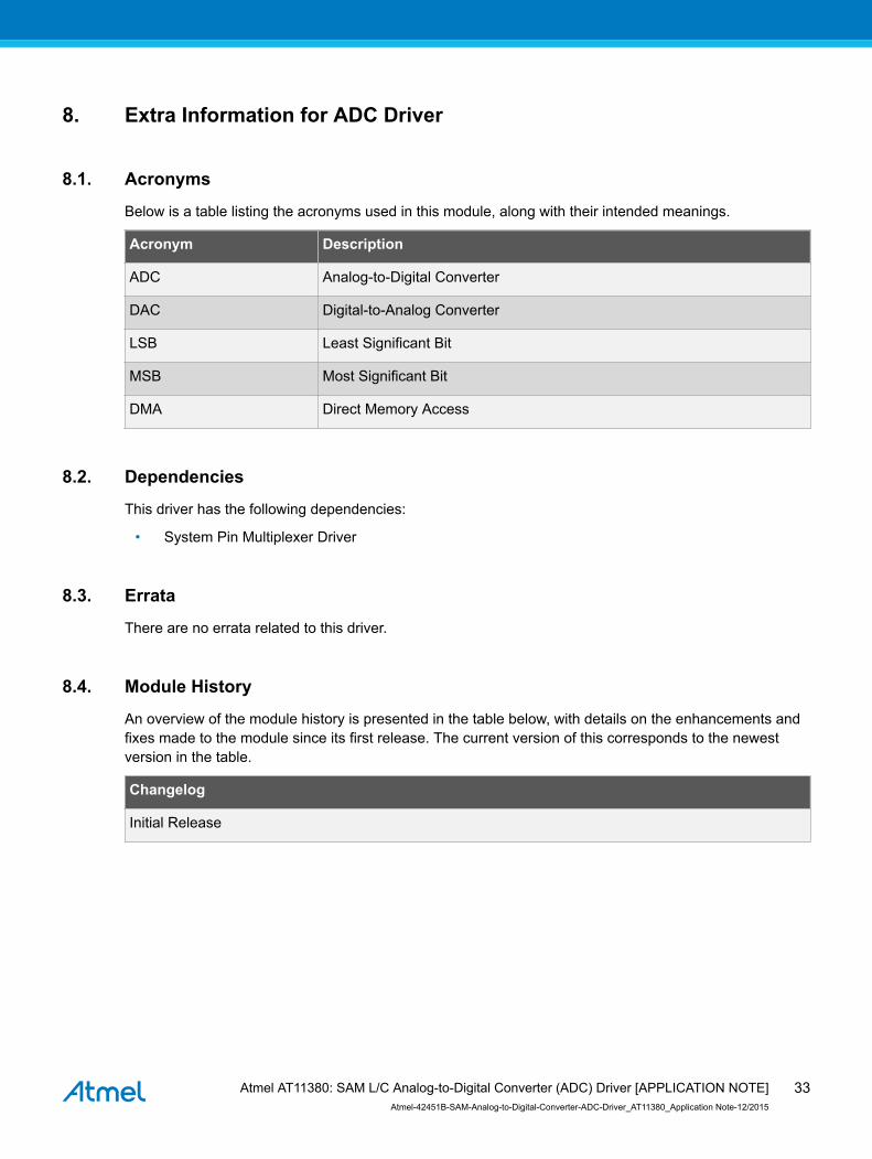
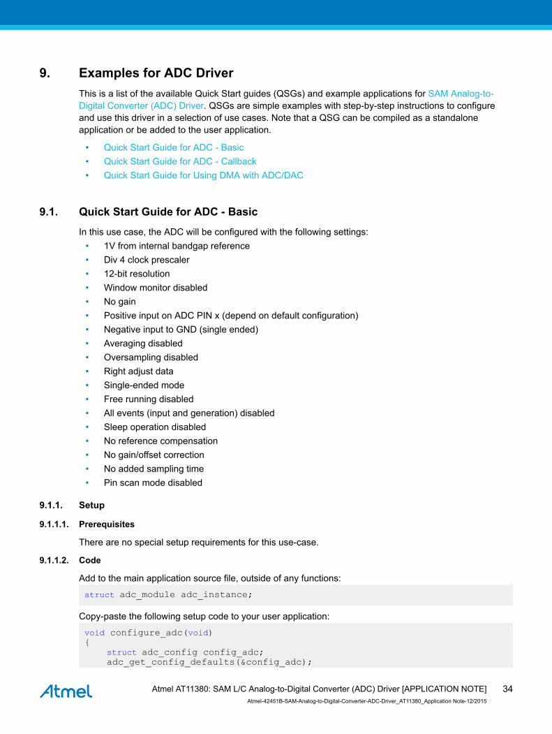
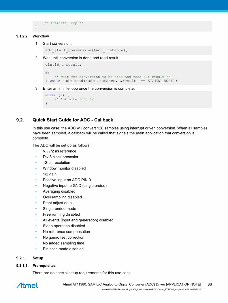
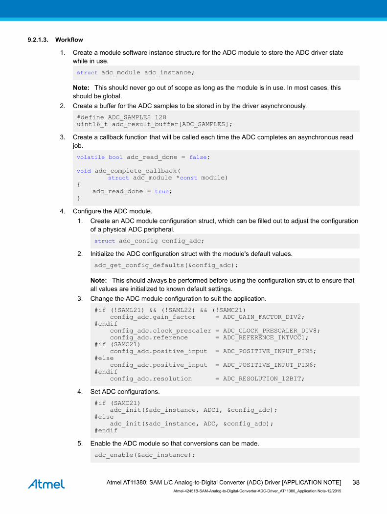
Related Documents