AT-1 AUTOMATIC TRANSMISSION Page DESCRIPTION AT-2 OPERATION AT-4 TROUBLESHOOTING AT-9 General Notes AT-9 General Troubleshooting AT-10 Preliminary Check AT-12 Mechanical System Tests AT-14 Automatic Shift Schedule AT-26 Neutral Start Switch AT-28 O/D Solenoid (w/ Cruise Control System) AT-28 A/T Fluid Temperature Warning System AT-29 ON-VEHICLE REPAIR AT-30 Valve Body AT-30 Throttle Cable AT-33 REMOVAL AND INSTALLATION OF TRANSMISSION AT-36 REMOVAL OF TRANSMISSION AT-38 INSTALLATION OF TRANSMISSION AT-44

Welcome message from author
This document is posted to help you gain knowledge. Please leave a comment to let me know what you think about it! Share it to your friends and learn new things together.
Transcript

AT-1
AUTOMATICTRANSMISSION
PageDESCRIPTION AT-2OPERATION AT-4TROUBLESHOOTING AT-9
General Notes AT-9General Troubleshooting AT-10Preliminary Check AT-12Mechanical System Tests AT-14Automatic Shift Schedule AT-26Neutral Start Switch AT-28O/D Solenoid (w/ Cruise Control System) AT-28A/T Fluid Temperature Warning System AT-29
ON-VEHICLE REPAIR AT-30Valve Body AT-30Throttle Cable AT-33
REMOVAL AND INSTALLATIONOF TRANSMISSION AT-36
REMOVAL OF TRANSMISSION AT-38INSTALLATION OF TRANSMISSION AT-44
AT-2 AUTOMATIC TRANSMISSION - Description
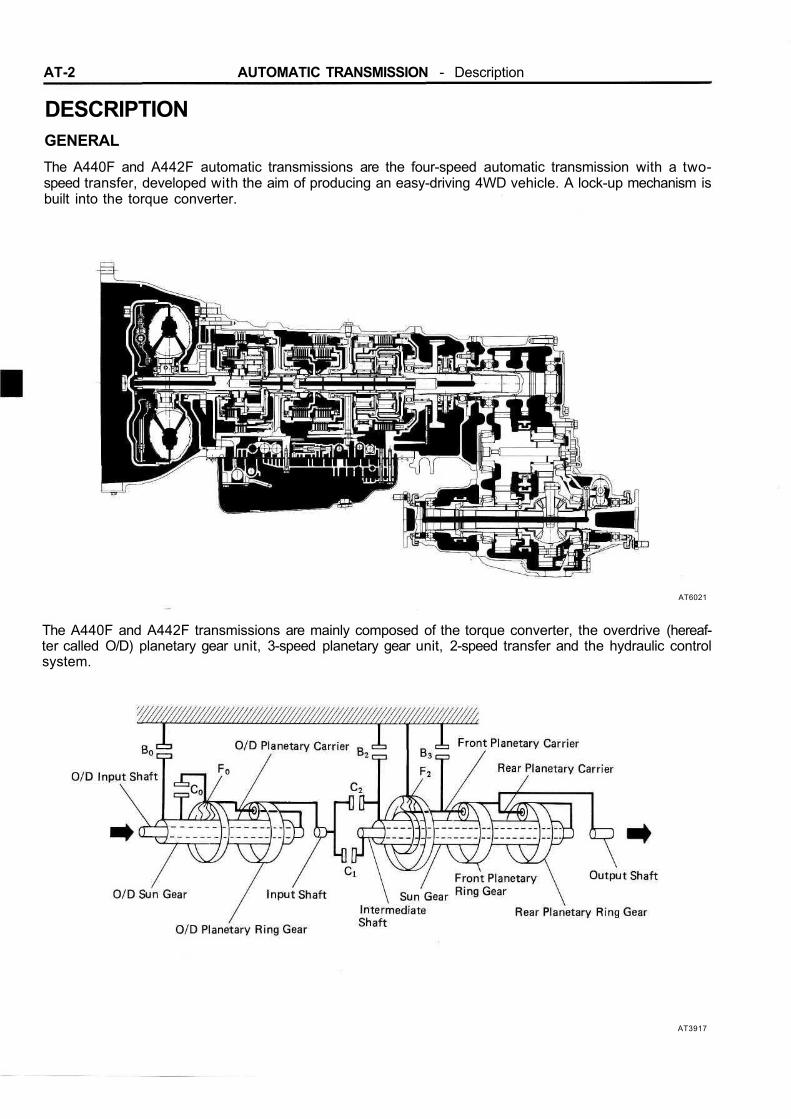
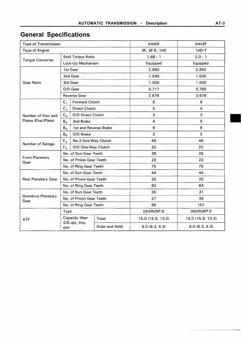
DESCRIPTIONGENERALThe A440F and A442F automatic transmissions are the four-speed automatic transmission with a two-speed transfer, developed with the aim of producing an easy-driving 4WD vehicle. A lock-up mechanism isbuilt into the torque converter.
AT6021
The A440F and A442F transmissions are mainly composed of the torque converter, the overdrive (hereaf-ter called O/D) planetary gear unit, 3-speed planetary gear unit, 2-speed transfer and the hydraulic controlsystem.
AT3917
AUTOMATIC TRANSMISSION - Description AT-3
General Specifications
AT-4 AUTOMATIC TRANSMISSION - Operation
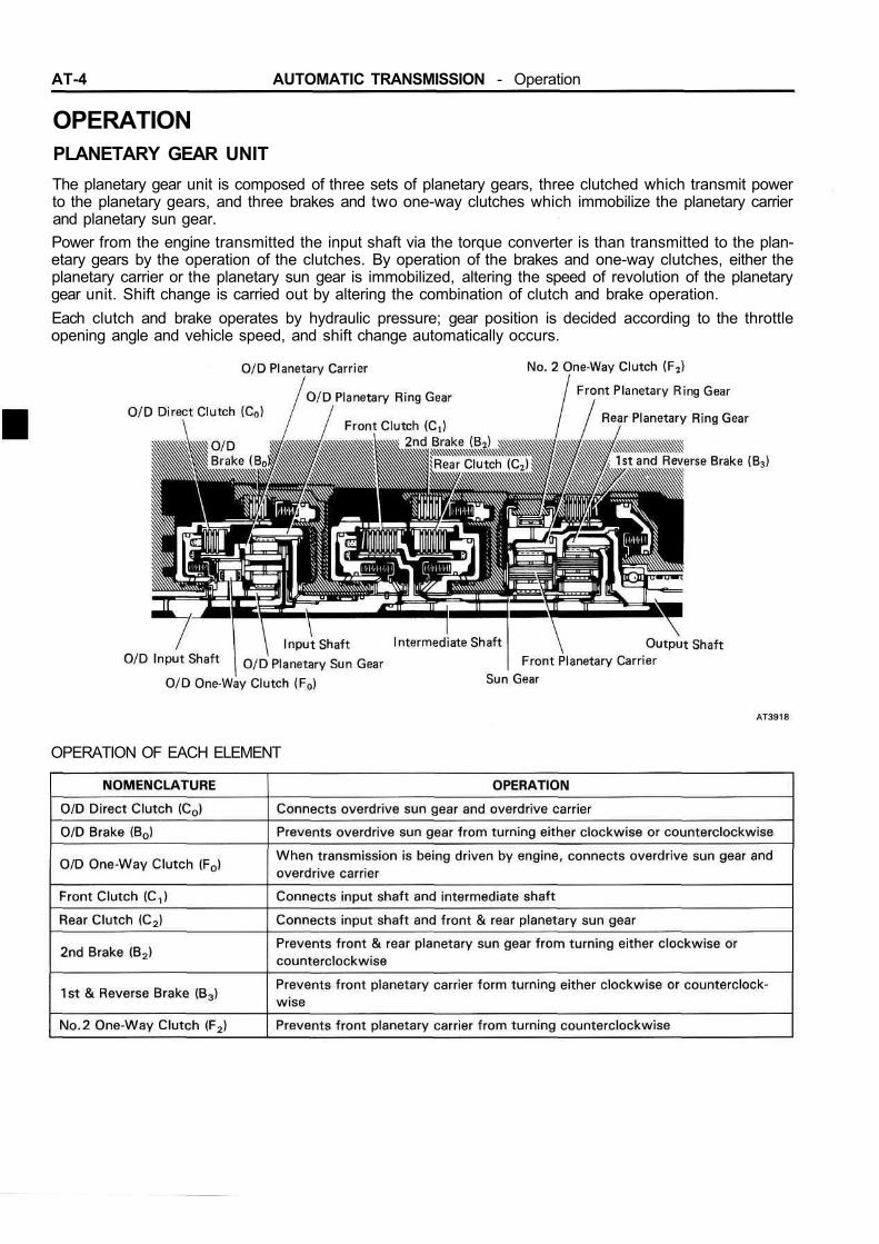
OPERATIONPLANETARY GEAR UNITThe planetary gear unit is composed of three sets of planetary gears, three clutched which transmit powerto the planetary gears, and three brakes and two one-way clutches which immobilize the planetary carrierand planetary sun gear.Power from the engine transmitted the input shaft via the torque converter is than transmitted to the plan-etary gears by the operation of the clutches. By operation of the brakes and one-way clutches, either theplanetary carrier or the planetary sun gear is immobilized, altering the speed of revolution of the planetarygear unit. Shift change is carried out by altering the combination of clutch and brake operation.Each clutch and brake operates by hydraulic pressure; gear position is decided according to the throttleopening angle and vehicle speed, and shift change automatically occurs.
OPERATION OF EACH ELEMENT

AUTOMATIC TRANSMISSION - Operation AT-5
OPERATING CONDITION FOR EACH GEAR
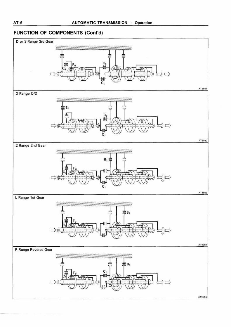
FUNCTION OF COMPONENTSThe conditions of operation for each gear position are shown on the following illustration:
AT-6 AUTOMATIC TRANSMISSION - Operation
FUNCTION OF COMPONENTS (Cont'd)
AUTOMATIC TRANSMISSION - Operation AT-7
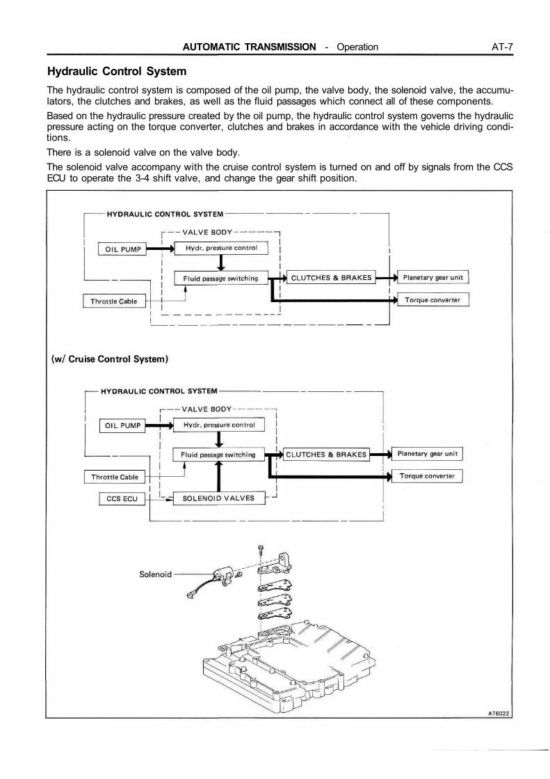
Hydraulic Control SystemThe hydraulic control system is composed of the oil pump, the valve body, the solenoid valve, the accumu-lators, the clutches and brakes, as well as the fluid passages which connect all of these components.Based on the hydraulic pressure created by the oil pump, the hydraulic control system governs the hydraulicpressure acting on the torque converter, clutches and brakes in accordance with the vehicle driving condi-tions.There is a solenoid valve on the valve body.The solenoid valve accompany with the cruise control system is turned on and off by signals from the CCSECU to operate the 3-4 shift valve, and change the gear shift position.
AT-8 AUTOMATIC TRANSMISSION - Operation
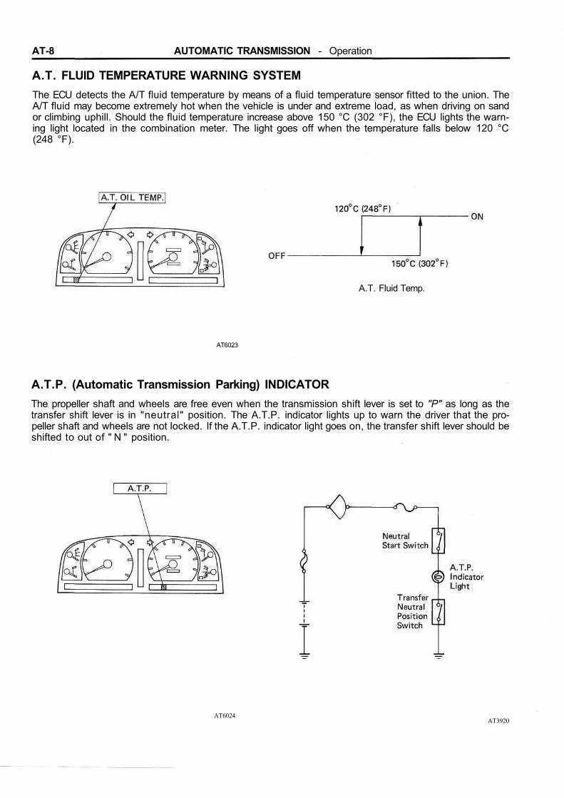
A.T. FLUID TEMPERATURE WARNING SYSTEMThe ECU detects the A/T fluid temperature by means of a fluid temperature sensor fitted to the union. TheA/T fluid may become extremely hot when the vehicle is under and extreme load, as when driving on sandor climbing uphill. Should the fluid temperature increase above 150 °C (302 °F), the ECU lights the warn-ing light located in the combination meter. The light goes off when the temperature falls below 120 °C(248 °F).
A.T. Fluid Temp.
AT6023
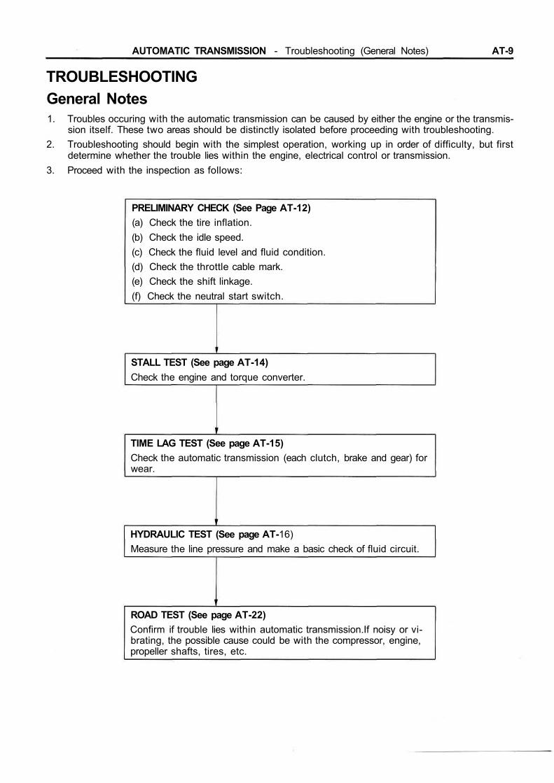
A.T.P. (Automatic Transmission Parking) INDICATORThe propeller shaft and wheels are free even when the transmission shift lever is set to "P" as long as thetransfer shift lever is in "neutral" position. The A.T.P. indicator lights up to warn the driver that the pro-peller shaft and wheels are not locked. If the A.T.P. indicator light goes on, the transfer shift lever should beshifted to out of " N " position.
AT6024AT3920
AUTOMATIC TRANSMISSION - Troubleshooting (General Notes) AT-9
TROUBLESHOOTINGGeneral Notes1. Troubles occuring with the automatic transmission can be caused by either the engine or the transmis-
sion itself. These two areas should be distinctly isolated before proceeding with troubleshooting.2. Troubleshooting should begin with the simplest operation, working up in order of difficulty, but first
determine whether the trouble lies within the engine, electrical control or transmission.3. Proceed with the inspection as follows:
PRELIMINARY CHECK (See Page AT-12)(a) Check the tire inflation.(b) Check the idle speed.(c) Check the fluid level and fluid condition.(d) Check the throttle cable mark.(e) Check the shift linkage.(f) Check the neutral start switch.
STALL TEST (See page AT-14)Check the engine and torque converter.
TIME LAG TEST (See page AT-15)Check the automatic transmission (each clutch, brake and gear) forwear.
HYDRAULIC TEST (See page AT-16)Measure the line pressure and make a basic check of fluid circuit.
ROAD TEST (See page AT-22)Confirm if trouble lies within automatic transmission.If noisy or vi-brating, the possible cause could be with the compressor, engine,propeller shafts, tires, etc.
AT-10 AUTOMATIC TRANSMISSION — Troubleshooting (General Troubleshooting)
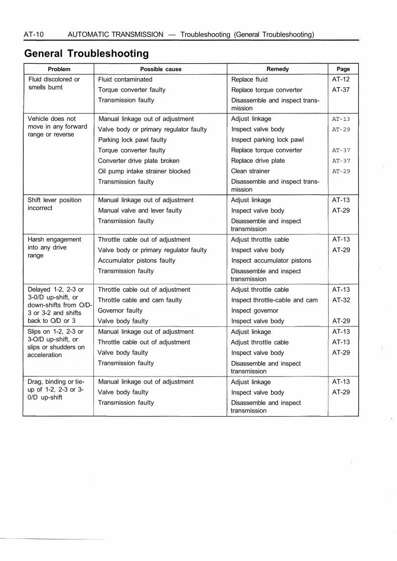
General TroubleshootingProblem Possible cause Remedy Page
Fluid discolored orsmells burnt
Fluid contaminatedTorque converter faultyTransmission faulty
Replace fluidReplace torque converterDisassemble and inspect trans-mission
AT-12AT-37
Vehicle does notmove in any forwardrange or reverse
Manual linkage out of adjustmentValve body or primary regulator faultyParking lock pawl faultyTorque converter faultyConverter drive plate brokenOil pump intake strainer blockedTransmission faulty
Adjust linkageInspect valve bodyInspect parking lock pawlReplace torque converterReplace drive plateClean strainerDisassemble and inspect trans-mission
AT-13
AT-29
AT-37
AT-37
AT-29
Shift lever positionincorrect
Manual linkage out of adjustmentManual valve and lever faultyTransmission faulty
Adjust linkageInspect valve bodyDisassemble and inspecttransmission
AT-13AT-29
Harsh engagementinto any driverange
Throttle cable out of adjustmentValve body or primary regulator faultyAccumulator pistons faultyTransmission faulty
Adjust throttle cableInspect valve bodyInspect accumulator pistonsDisassemble and inspecttransmission
AT-13AT-29
Delayed 1-2, 2-3 or3-0/D up-shift, ordown-shifts from O/D-3 or 3-2 and shiftsback to O/D or 3
Throttle cable out of adjustmentThrottle cable and cam faultyGovernor faultyValve body faulty
Adjust throttle cableInspect throttle-cable and camInspect governorInspect valve body
AT-13AT-32
AT-29Slips on 1-2, 2-3 or3-O/D up-shift, orslips or shudders onacceleration
Manual linkage out of adjustmentThrottle cable out of adjustmentValve body faultyTransmission faulty
Adjust linkageAdjust throttle cableInspect valve bodyDisassemble and inspecttransmission
AT-13AT-13AT-29
Drag, binding or tie-up of 1-2, 2-3 or 3-0/D up-shift
Manual linkage out of adjustmentValve body faultyTransmission faulty
Adjust linkageInspect valve bodyDisassemble and inspecttransmission
AT-13AT-29

AUTOMATIC TRANSMISSION - Troubleshooting (General Troubleshooting) AT-11
General Troubleshooting (Cout'd)Problem Possible cause Remedy Page
No lock-up Valve body faultyTorque converter faultyTransmission faulty
Inspect valve bodyReplace torque converterDisassemble and inspect trans-mission
AT-29AT-44
Harsh down-shift Throttle cable out of adjustmentThrottle cable and cam faultyAccumulator pistons faultyValve body faultyTransmission faulty
Adjust throttle cableInspect throttle cable and camInspect accumulator pistonsInspect valve bodyDisassemble and inspecttransmission
AT-13AT-32
AT-29
No down-shift whencoasting
Governor faultyValve body faulty
Inspect governorInspect valve body AT-29
Down-shift occurstoo quickly or toolate while coasting
Throttle cable out of adjustmentGovernor faultyValve body faultyTransmission faulty
Adjust throttle cableInspect governorInspect valve bodyDisassemble and inspecttransmission
AT-13
AT-29
No O/D-3 , 3-2 or2-1 kick-down
Throttle cable out of adjustmentGovernor faultyValve body faulty
Adjust throttle cableInspect governorInspect valve body
AT-13
AT-29No engine brakingin 2 or L range
Valve body faultyTransmission faulty
Inspect valve bodyDisassemble and inspecttransmission
AT-29
Vehicle does not holdinP
Manual linkage out of adjustmentParking lock pawl cam and spring faulty
Adjust linkageInspect cam and spring
AT-13
AT-12 AUTOMATIC TRANSMISSION - Troubleshooting (Preliminary Check)
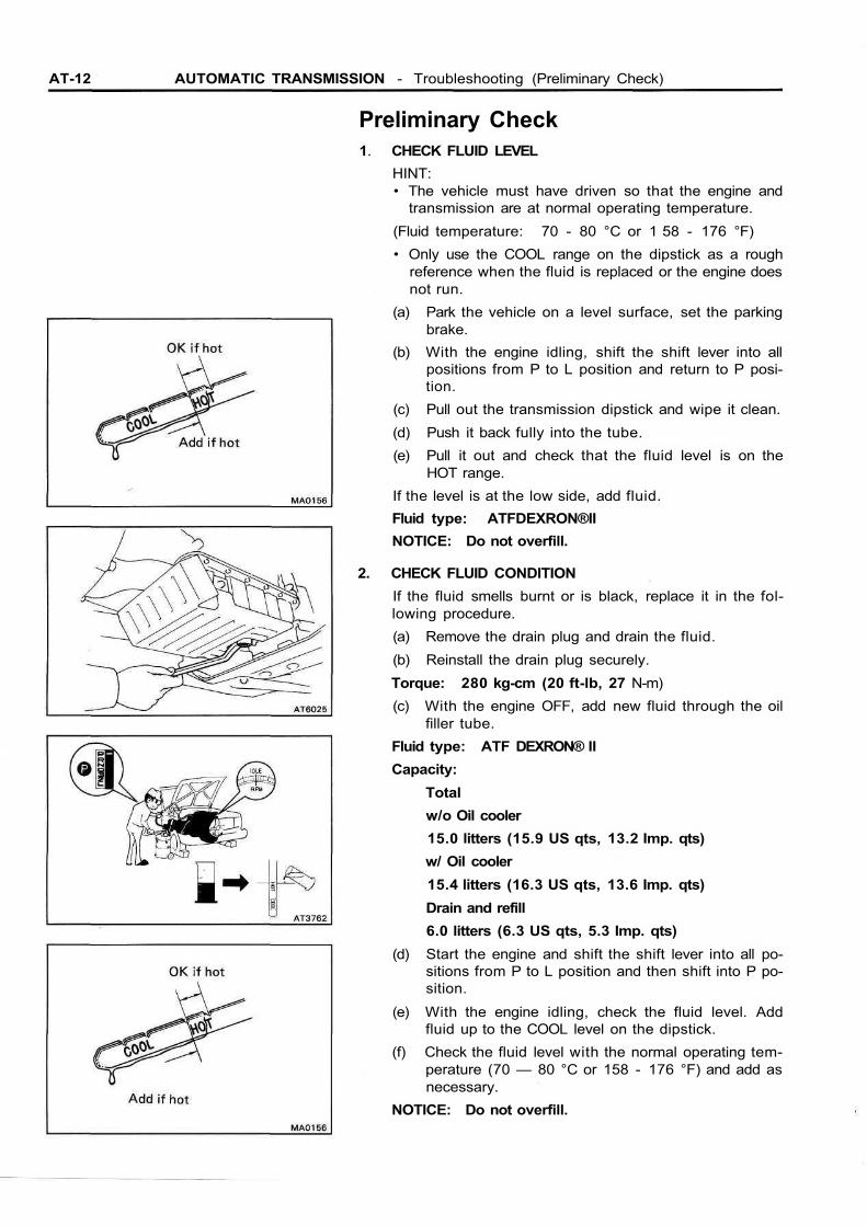
Preliminary Check1. CHECK FLUID LEVEL
HINT:• The vehicle must have driven so that the engine and
transmission are at normal operating temperature.(Fluid temperature: 70 - 80 °C or 1 58 - 176 °F)• Only use the COOL range on the dipstick as a rough
reference when the fluid is replaced or the engine doesnot run.
(a) Park the vehicle on a level surface, set the parkingbrake.
(b) With the engine idling, shift the shift lever into allpositions from P to L position and return to P posi-tion.
(c) Pull out the transmission dipstick and wipe it clean.(d) Push it back fully into the tube.(e) Pull it out and check that the fluid level is on the
HOT range.If the level is at the low side, add fluid.Fluid type: ATFDEXRON®IINOTICE: Do not overfill.
2. CHECK FLUID CONDITIONIf the fluid smells burnt or is black, replace it in the fol-lowing procedure.(a) Remove the drain plug and drain the fluid.(b) Reinstall the drain plug securely.Torque: 280 kg-cm (20 ft-lb, 27 N-m)(c) With the engine OFF, add new fluid through the oil
filler tube.Fluid type: ATF DEXRON® IICapacity:
Totalw/o Oil cooler15.0 litters (15.9 US qts, 13.2 Imp. qts)w/ Oil cooler15.4 litters (16.3 US qts, 13.6 Imp. qts)Drain and refill6.0 litters (6.3 US qts, 5.3 Imp. qts)
(d) Start the engine and shift the shift lever into all po-sitions from P to L position and then shift into P po-sition.
(e) With the engine idling, check the fluid level. Addfluid up to the COOL level on the dipstick.
(f) Check the fluid level with the normal operating tem-perature (70 — 80 °C or 158 - 176 °F) and add asnecessary.
NOTICE: Do not overfill.

AUTOMATIC TRANSMISSION - Troubleshooting (Preliminary Check) AT-13
3. INSPECT THROTTLE CABLE(a) Cheek that the throttle cable is installed correctly
and not bent.(b) With the throttle valve fully closed, measure the dis-
tance between the end of the boot and stopper onthe cable.
Standard distance:Fully closed 0.5 — 1.5 mm
(0.020 - 0.059 in.)Fully opened 32 — 34 mm
(1.260 - 1.339 in.)If the distance is not standard, adjust the cable by the ad-justing nuts.
4. INSPECT TRANSMISSION SHIFT LEVER POSITIONWhen shifting the shift lever from the N position to otherpositions, check that the lever can be shifted smoothlyand accurately to each position and that the position in-dicator correctly indicates the position.If the indicator is not aligned with the correct position,carry out the following adjustment procedures.(a) Loosen the nut on the control rod.(b) Push the control shaft lever fully toward the rear of
the vehicle.(c) Return the control shaft lever two notches to N po-
sition.(d) Set the shift lever to N position.(e) While holding the shift lever lightly toward the R po-
sition side, tighten the control rod nut.(f) Start the engine and make sure that the vehicle
moves forward when shifting the lever from the N toD position and reverse when shifting it to the R po-sition.
5. INSPECT NEUTRAL START SWITCHCheck that the engine can be started with the shift leveronly in the N or P position, but not in other positions.If not as started above, carry out the following adjust-ment procedures.(a) Loosen the neutral start switch bolts and set the
shift lever to the N position.(b) Align the groove and neutral basic line.(c) Hold in position and tighten the bolts.Torque: 130 kg-cm (9 ft-lb, 13 N-m)
6. INSPECT IDLE SPEED (N RANGE)Connect tachometer test probe to the check connectorterminal IG Q>, inspect the idle speed.Idle speed: 650 rpm
AT-14 AUTOMATIC TRANSMISSION — Troubleshooting (Mechanical System Tests)
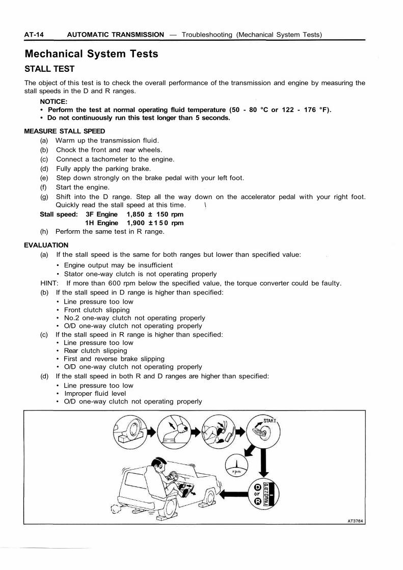
Mechanical System TestsSTALL TESTThe object of this test is to check the overall performance of the transmission and engine by measuring thestall speeds in the D and R ranges.
NOTICE:• Perform the test at normal operating fluid temperature (50 - 80 °C or 122 - 176 °F).• Do not continuously run this test longer than 5 seconds.
MEASURE STALL SPEED(a) Warm up the transmission fluid.(b) Chock the front and rear wheels.(c) Connect a tachometer to the engine.(d) Fully apply the parking brake.(e) Step down strongly on the brake pedal with your left foot.(f) Start the engine.(g) Shift into the D range. Step all the way down on the accelerator pedal with your right foot.
Quickly read the stall speed at this time. \Stall speed: 3F Engine 1,850 ± 150 rpm
1H Engine 1,900 ± 1 5 0 rpm(h) Perform the same test in R range.
EVALUATION(a) If the stall speed is the same for both ranges but lower than specified value:
• Engine output may be insufficient• Stator one-way clutch is not operating properly
HINT: If more than 600 rpm below the specified value, the torque converter could be faulty.(b) If the stall speed in D range is higher than specified:
• Line pressure too low• Front clutch slipping• No.2 one-way clutch not operating properly• O/D one-way clutch not operating properly
(c) If the stall speed in R range is higher than specified:• Line pressure too low• Rear clutch slipping• First and reverse brake slipping• O/D one-way clutch not operating properly
(d) If the stall speed in both R and D ranges are higher than specified:• Line pressure too low• Improper fluid level• O/D one-way clutch not operating properly
AUTOMATIC TRANSMISSION - Troubleshooting (Mechanical System Tests) AT-15
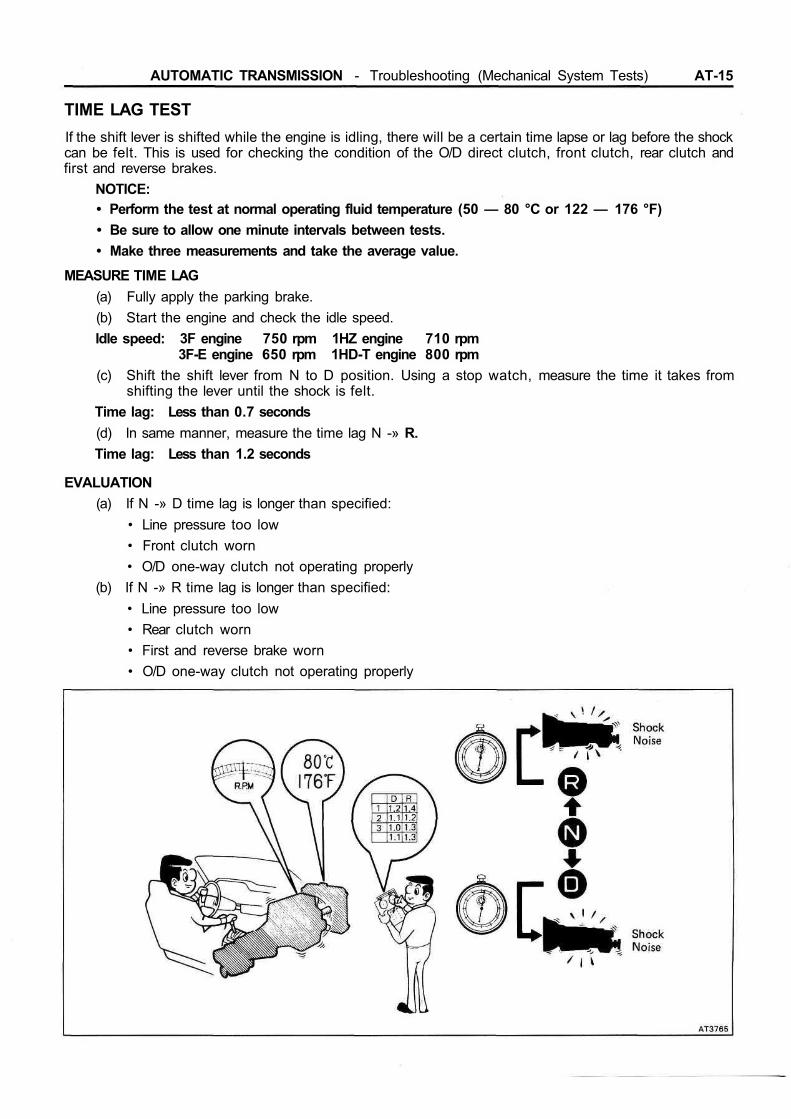
TIME LAG TESTIf the shift lever is shifted while the engine is idling, there will be a certain time lapse or lag before the shockcan be felt. This is used for checking the condition of the O/D direct clutch, front clutch, rear clutch andfirst and reverse brakes.
NOTICE:• Perform the test at normal operating fluid temperature (50 — 80 °C or 122 — 176 °F)• Be sure to allow one minute intervals between tests.• Make three measurements and take the average value.
MEASURE TIME LAG(a) Fully apply the parking brake.(b) Start the engine and check the idle speed.Idle speed: 3F engine 750 rpm 1HZ engine 710 rpm
3F-E engine 650 rpm 1HD-T engine 800 rpm(c) Shift the shift lever from N to D position. Using a stop watch, measure the time it takes from
shifting the lever until the shock is felt.Time lag: Less than 0.7 seconds(d) In same manner, measure the time lag N -» R.Time lag: Less than 1.2 seconds
EVALUATION(a) If N -» D time lag is longer than specified:
• Line pressure too low• Front clutch worn• O/D one-way clutch not operating properly
(b) If N -» R time lag is longer than specified:• Line pressure too low• Rear clutch worn• First and reverse brake worn• O/D one-way clutch not operating properly
AT-16 AUTOMATIC TRANSMISSION — Troubleshooting (Mechanical System Tests)
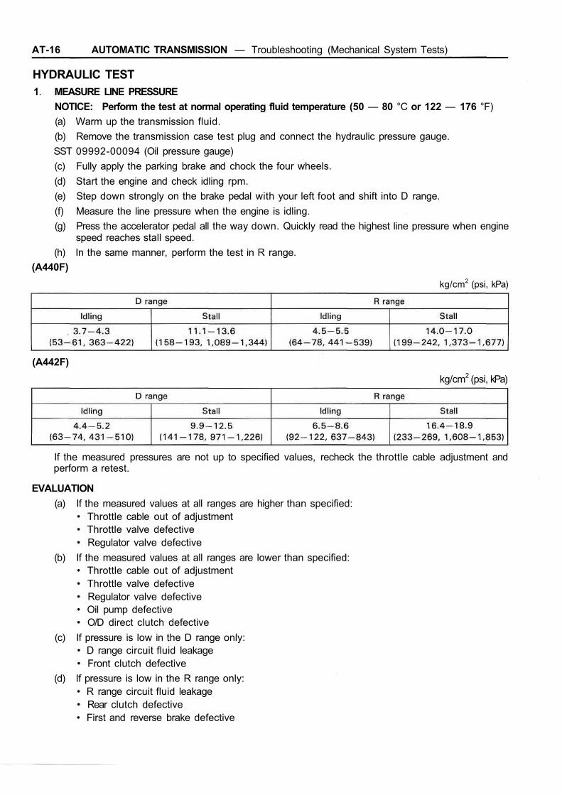
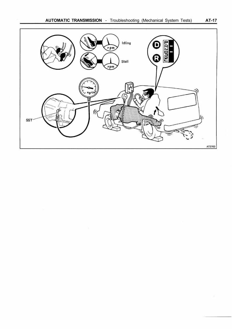
HYDRAULIC TEST1. MEASURE LINE PRESSURE
NOTICE: Perform the test at normal operating fluid temperature (50 — 80 °C or 122 — 176 °F)(a) Warm up the transmission fluid.(b) Remove the transmission case test plug and connect the hydraulic pressure gauge.SST 09992-00094 (Oil pressure gauge)(c) Fully apply the parking brake and chock the four wheels.(d) Start the engine and check idling rpm.(e) Step down strongly on the brake pedal with your left foot and shift into D range.(f) Measure the line pressure when the engine is idling.(g) Press the accelerator pedal all the way down. Quickly read the highest line pressure when engine
speed reaches stall speed.(h) In the same manner, perform the test in R range.
(A440F)kg/cm2 (psi, kPa)
(A442F)kg/cm2 (psi, kPa)
If the measured pressures are not up to specified values, recheck the throttle cable adjustment andperform a retest.
EVALUATION(a) If the measured values at all ranges are higher than specified:
• Throttle cable out of adjustment• Throttle valve defective• Regulator valve defective
(b) If the measured values at all ranges are lower than specified:• Throttle cable out of adjustment• Throttle valve defective• Regulator valve defective• Oil pump defective• O/D direct clutch defective
(c) If pressure is low in the D range only:• D range circuit fluid leakage• Front clutch defective
(d) If pressure is low in the R range only:• R range circuit fluid leakage• Rear clutch defective• First and reverse brake defective
AUTOMATIC TRANSMISSION - Troubleshooting (Mechanical System Tests) AT-17

AT-18 AUTOMATIC TRANSMISSION — Troubleshooting (Mechanical System Tests)
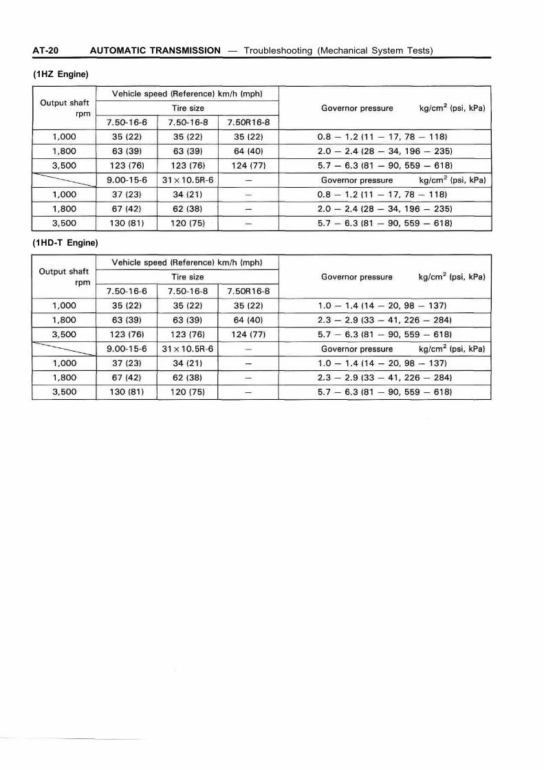
2. MEASURE GOVERNOR PRESSURENOTICE:• Perform the test at normal operating fluid temperature (50 — 80 °C or 122 — 176 °F).• Measurement can be made with a 1,000 rpm test, but if tests are to be made at 1,800 rpm and
3,500 rpm, it would be safer to do it on road or using a chassis dynamometer because an on-standtest could be hazardous.
(a) Warm up the transmission fluid.(b) (Part-time) Shift the transfer shift lever to the " H 2 " position.
(Full-time) Lock the center differential.(c) (Part-time) Chock the front wheels.
(Full-time) Remove front propeller shaft.(d) (Part-time) Jack up rear of the vehicle and support it on stands.
(Full-time) Jack up the vehicle and support it on stands.(e) Remove the transmission case test plug and connect the hydraulic pressure gauge.SST 09992-00094 (Oil pressure gauge)(f) Check that the parking brake is not applied.(g) Start the engine.(h) Shift into the D range and measure the governor pressure at the speeds specified in the table.
[Australia](3F-E Engine)
(1HD-T Engine)
[Europe](3F-E Engine)

AUTOMATIC TRANSMISSION — Troubleshooting (Mechanical System Tests) AT-19
(1HZ Engine)
(1HD-T Engine)
[Middle East]
[Others](3F-Engine)
AT-20 AUTOMATIC TRANSMISSION — Troubleshooting (Mechanical System Tests)
(1HZ Engine)
(1HD-T Engine)

AUTOMATIC TRANSMISSION - Troubleshooting (Mechanical System Tests) AT-21
EVALUATIONIf governor pressure is defective:• Line pressure defective• Fluid leakage in governor pressure circuit• Governor valve operation defective
AT-22 AUTOMATIC TRANSMISSION - Troubleshooting (Mechanical System Tests)
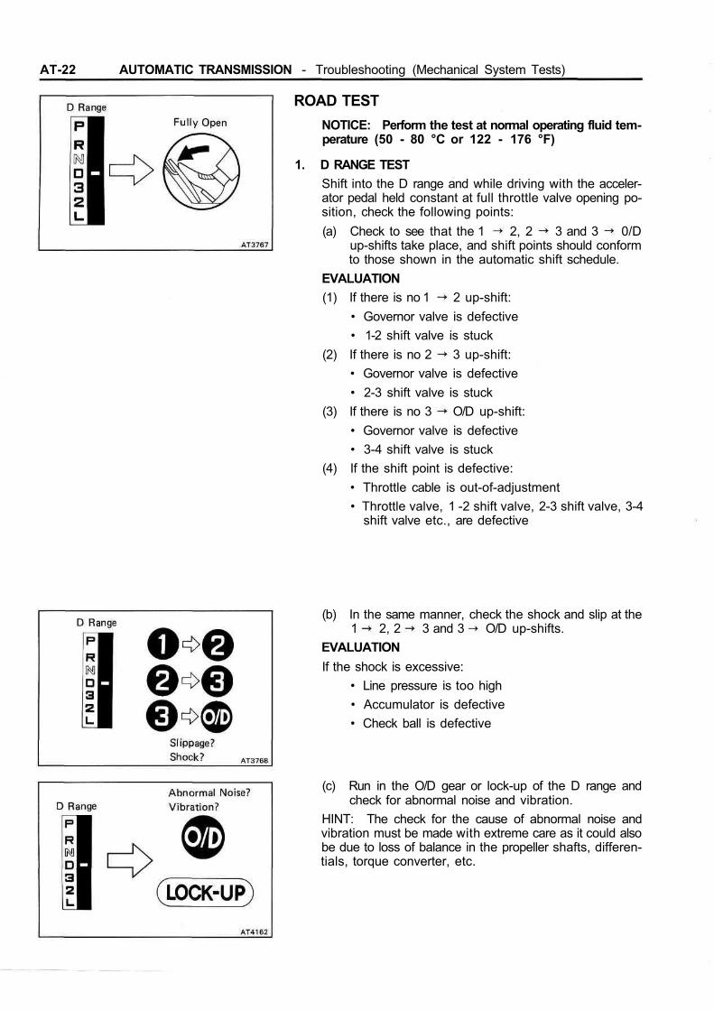
ROAD TESTNOTICE: Perform the test at normal operating fluid tem-perature (50 - 80 °C or 122 - 176 °F)
1. D RANGE TESTShift into the D range and while driving with the acceler-ator pedal held constant at full throttle valve opening po-sition, check the following points:(a) Check to see that the 1 2, 2 3 and 3 0/D
up-shifts take place, and shift points should conformto those shown in the automatic shift schedule.
EVALUATION(1) If there is no 1 2 up-shift:
• Governor valve is defective• 1-2 shift valve is stuck
(2) If there is no 2 3 up-shift:• Governor valve is defective• 2-3 shift valve is stuck
(3) If there is no 3 O/D up-shift:• Governor valve is defective• 3-4 shift valve is stuck
(4) If the shift point is defective:• Throttle cable is out-of-adjustment• Throttle valve, 1 -2 shift valve, 2-3 shift valve, 3-4
shift valve etc., are defective
(b) In the same manner, check the shock and slip at the1 2, 2 3 and 3 O/D up-shifts.
EVALUATIONIf the shock is excessive:
• Line pressure is too high• Accumulator is defective• Check ball is defective
(c) Run in the O/D gear or lock-up of the D range andcheck for abnormal noise and vibration.
HINT: The check for the cause of abnormal noise andvibration must be made with extreme care as it could alsobe due to loss of balance in the propeller shafts, differen-tials, torque converter, etc.

AUTOMATIC TRANSMISSION — Troubleshooting (Mechanical System Tests) AT-23
(d) While running in the 2nd, 3rd, or O/D gear of the Drange, check to see that the possible kick-down ve-hicle speed limits for 2 1,3 2 or O/D 3 kick-downs conform to those indicated on the automaticshift schedule.
(e) Check for abnormal shock and slip at kick-down.
(f) Check for the lock-up mechanism.(1) Drive in O/D gear of the D range, at a steady
speed (lock-up ON) of about 85 km/h (53 mph).(2) Lightly depress the accelerator pedal and check
that the engine rpm does not change abruptly.If there is a big jump in engine rpm, there is no lock-up.
2. 3 RANGE TEST(a) While running in the 3rd gear of the 3 range, check
to see that there is no up-shift to the O/D gear.
(b) Check for abnormal noise at acceleration and decel-eration, and for shock at up-shift and down-shift.
3. 2 RANGE TEST(a) While running in the 2nd gear of the 2 range, check
to see that there is no up-shift to the 3rd gear.(b) While running in the 2nd gear of the 2 range, check
to see that there is no down-shift to the 1st gear.

AT-24 AUTOMATIC TRANSMISSION - Troubleshooting (Mechanical System Tests)
(c) While running in the 2nd gear of the 2 range, releasethe accelerator pedal and check the engine brakingeffect.
(d) Check for abnormal noise during acceleration anddeceleration.
4. L RANGE TEST(a) While running in the L range, check to see that there
is no up-shift to the 2nd gear.
(b) While running in the L range, release the acceleratorpedal and check the engine braking effect.
EVALUATIONIf there is no engine braking effect:
• First and reverse brake is defective
(c) Check for abnormal noise during acceleration anddeceleration.

AUTOMATIC TRANSMISSION - Troubleshooting (Mechanical System Tests) AT-25
5. R RANGE TESTShift into the R range and, while starting at full throttle,check for slipping.
6. P RANGE TESTStop the vehicle on a gradient (more than 9 %) and aftershifting into the P range, release the parking brake.Then check to see that the parking lock pawl holds thevehicle in place.

AT-26 AUTOMATIC TRANSMISSION - Troubleshooting (Automatic Shift Schedule)
Automatic Shift Schedule(Australia) km/h (mph)
(Europe) km/h (mph)
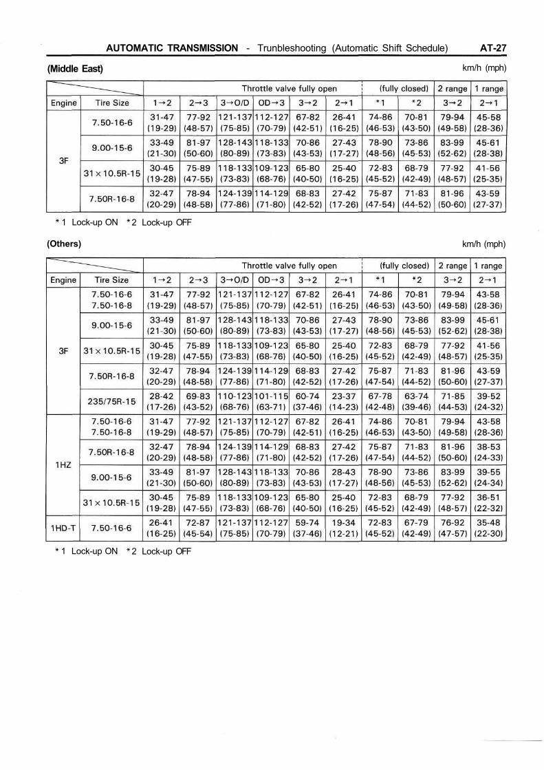
AUTOMATIC TRANSMISSION - Trunbleshooting (Automatic Shift Schedule) AT-27
(Middle East) km/h (mph)
km/h (mph)(Others)
1 Lock-up ON 2 Lock-up OFF
1 Lock-up ON 2 Lock-up OFF

AT-28 AUTOMATIC TRANSMISSION Troubleshooting (Automatic Shift Schedule,Neutral Start Switch, O/D Solenoid)
km/h (mph)
1 Lock-up ON 2 Lock-up OFF
Neutral Start SwitchINPSECT NEUTRAL START SWITCH
Using an ohmmeter, check the ccontinuity of the termi-nals for each switch position shown in the table below.
If continuity between terminals is not as specified, re-place the switch.
O/D Solenoid (w/ Cruise ControlSystem)CHECK SOLENOID SEAL
If there is foreign material in the solenoid valve, there willbe no fluid control even with solenoid operation.(a) Applying compressed air, check that the solenoid
valve opens.(b) When supply battery voltage to the solenoid, check
that the solenoid valve does not leak the air.If operation is not as specified, replace the solenoid.
AUTOMATIC TRANSMISSION Troubleshooting (A/T FluidTemperature Warning System) AT-29
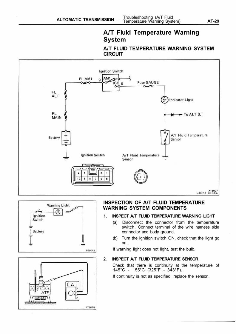
A/T Fluid Temperature WarningSystemA/T FLUID TEMPERATURE WARNING SYSTEMCIRCUIT
INSPECTION OF A/T FLUID TEMPERATUREWARNING SYSTEM COMPONENTS1. INSPECT A/T FLUID TEMPERATURE WARNING LIGHT
(a) Disconnect the connector from the temperatureswitch. Connect terminal of the wire harness sideconnector and body ground.
(b) Turn the ignition switch ON, check that the light goon.
If warning light does not light, test the bulb.
2. INSPECT A/T FLUID TEMPERATURE SENSORCheck that there is continuity at the temperature of145°C - 155°C (325°F - 343°F).If continuity is not as specified, replace the sensor.

AT-30 AUTOMATIC TRANSMISSION - On-Vehicle Repair
ON-VEHICLE REPAIRValve BodyREMOVAL OF VALVE BODY1. MAKE PLATE TO RETAIN ACCUMULATOR PISTONS
A retainer is helpful for holding accumulator pistons inthe case during removal and installation of the valvebody.The plate may be made from aluminum or plastic.
2. REMOVE TRANSMISSION AND TRANSFER UNDERCOVERS
3. CLEAN TRANSMISSION EXTERIORTo help prevent contamination, clean the exterior of thetransmission.
4. DRAIN TRANSMISSION FLUIDRemove the drain plug and drain fluid into a suitable con-tainer.
5. REMOVE OIL PAN AND GASKETNOTICE: Some fluid will remain in the oil pan. Be carefulnot to damage the filler tube.Insert the blade of SST between the transmission and oilpan, cut off applied sealer.SST 09032-00010
6. REMOVE OIL STRAINER AND GASKET(a) Remove the ten bolts and oil strainer.NOTICE: Be careful as some oil will come out with thefilter.(b) Remove the gasket.
7. REMOVE VALVE BODY(a) Remove the eighteen bolts.HINT: Support the valve body by hand to prevent itfrom falling.
AUTOMATIC TRANSMISSION - On-Vehicle Repair AT-31
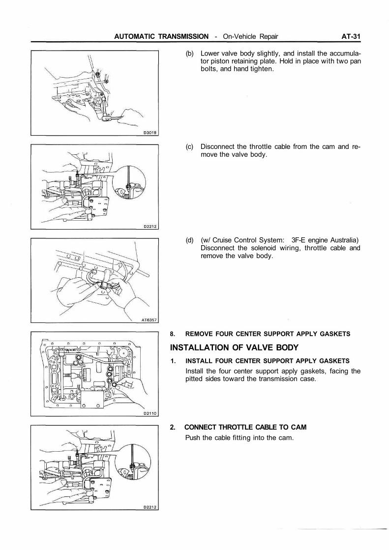
(b) Lower valve body slightly, and install the accumula-tor piston retaining plate. Hold in place with two panbolts, and hand tighten.
(c) Disconnect the throttle cable from the cam and re-move the valve body.
(d) (w/ Cruise Control System: 3F-E engine Australia)Disconnect the solenoid wiring, throttle cable andremove the valve body.
8. REMOVE FOUR CENTER SUPPORT APPLY GASKETS
INSTALLATION OF VALVE BODY1. INSTALL FOUR CENTER SUPPORT APPLY GASKETS
Install the four center support apply gaskets, facing thepitted sides toward the transmission case.
2. CONNECT THROTTLE CABLE TO CAMPush the cable fitting into the cam.

AT-32 AUTOMATIC TRANSMISSION - On-Vehicle Repair
(w/ Cruise Control System)Push the cable fitting into the cam and connect the sole-noid wiring connector.
3. INSTALL VALVE BODY(a) Align the manual valve lever with the manual valve.
(b) Remove the two pan bolts, and slide out the accu-mulator retaining plate.
4. INSTALL VALVE BODY BOLTS(a) Install the three bolts indicated by the arrows.(b) Install the other bolts.(c) Check that the manual valve lever contacts the cen-
ter of the roller at the tip of the detent spring.(d) Tighten the bolts.Torque: 100 kg-cm (7 ft-lb, 10 Nm)
5. INSTALL OIL STRAINERBe sure the strainer is clean. Install a new gasket andstrainer.Torque: 5 mm bolt 55 kg-cm (48 in.-lb, 5.4 Nm)
6 mm bolt 100 kg-cm (7 ft-lb, 10 Nm)
AUTOMATIC TRANSMISSION - On-Vehicle Repair AT-33
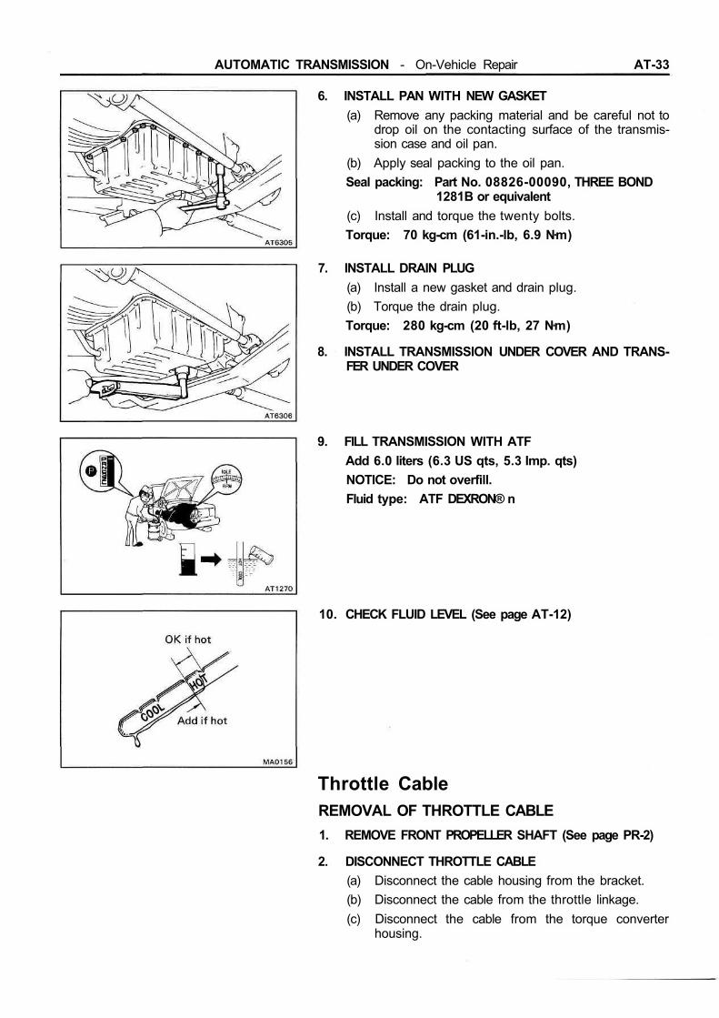
6. INSTALL PAN WITH NEW GASKET(a) Remove any packing material and be careful not to
drop oil on the contacting surface of the transmis-sion case and oil pan.
(b) Apply seal packing to the oil pan.Seal packing: Part No. 08826-00090, THREE BOND
1281B or equivalent(c) Install and torque the twenty bolts.Torque: 70 kg-cm (61-in.-lb, 6.9 Nm)
7. INSTALL DRAIN PLUG(a) Install a new gasket and drain plug.(b) Torque the drain plug.Torque: 280 kg-cm (20 ft-lb, 27 Nm)
8. INSTALL TRANSMISSION UNDER COVER AND TRANS-FER UNDER COVER
9. FILL TRANSMISSION WITH ATFAdd 6.0 liters (6.3 US qts, 5.3 Imp. qts)NOTICE: Do not overfill.Fluid type: ATF DEXRON® n
10. CHECK FLUID LEVEL (See page AT-12)
Throttle CableREMOVAL OF THROTTLE CABLE1. REMOVE FRONT PROPELLER SHAFT (See page PR-2)
2. DISCONNECT THROTTLE CABLE(a) Disconnect the cable housing from the bracket.(b) Disconnect the cable from the throttle linkage.(c) Disconnect the cable from the torque converter
housing.
AT-34 AUTOMATIC TRANSMISSION - On-Vehicle Repair
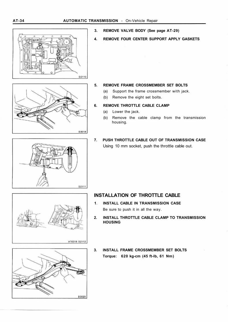
3. REMOVE VALVE BODY (See page AT-29)
4. REMOVE FOUR CENTER SUPPORT APPLY GASKETS
5. REMOVE FRAME CROSSMEMBER SET BOLTS(a) Support the frame crossmember with jack.(b) Remove the eight set bolts.
6. REMOVE THROTTLE CABLE CLAMP(a) Lower the jack.(b) Remove the cable clamp from the transmission
housing.
7. PUSH THROTTLE CABLE OUT OF TRANSMISSION CASEUsing 10 mm socket, push the throttle cable out.
INSTALLATION OF THROTTLE CABLE1. INSTALL CABLE IN TRANSMISSION CASE
Be sure to push it in all the way.
2. INSTALL THROTTLE CABLE CLAMP TO TRANSMISSIONHOUSING
3. INSTALL FRAME CROSSMEMBER SET BOLTSTorque: 620 kg-cm (45 ft-lb, 61 Nm)

AUTOMATIC TRANSMISSION - On-Vehicle Repair AT-35
4. INSTALL FOUR CENTER SUPPORT APPLY GASKETS
5. INSTALL VALVE BODY (See page AT-31)
6. INSTALL FRONT PROPELLER SHAFT (See page PR-2)
7. IF THROTTLE CABLE IS NEW, PAINT MARK ON INNERCABLEHINT: New cables do not have a cable stopper installed.Therefore to mark adjustment possible, paint a mark asdescribed below.(a) Connect the throttle cable to the throttle cam of
valve body.(b) Pull the inner cable lightly until resistance is felt, and
hold it.(c) Paint a mark as shown, about 4 mm (0.16 in.) in
width.(d) Pull the inner cable fully, measure the cable stroke.Cable stroke: 33 ± 1 mm (1.30 ± 0.04 in.)
8. CONNECT THROTTLE CABLE(a) Connect the cable to the throttle linkage.(b) Connect the cable housing to the bracket on the
valve cover.
9. ADJUST THROTTLE CABLE (See page AT-13)
10. FILL TRANSMISSION WITH ATFAdd 6 liters (6.3 US qts, 5.3 Imp. qts)NOTICE: Do not overfill.Fluid type: ATF DEXRON® II
11. CHECK FLUID LEVEL (See page AT-12)

AT-36 AUTOMATIC TRANSMISSION — Removal and Installation of Transmission
REMOVAL AND INSTALLATION OFTRANSMISSION
Remove and install the parts as shown.
AUTOMATIC TRANSMISSION — Removal and Installation of Transmission AT-37
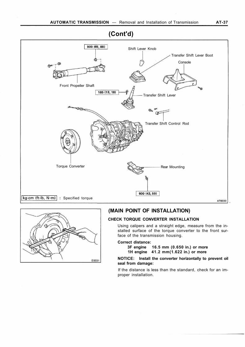
(Cont'd)
(MAIN POINT OF INSTALLATION)CHECK TORQUE CONVERTER INSTALLATION
Using calipers and a straight edge, measure from the in-stalled surface of the torque converter to the front sur-face of the transmission housing.Correct distance:
3F engine 16.5 mm (0.650 in.) or more1H engine 41.2 mm(1.622 in.) or more
NOTICE: Install the converter horizontally to prevent oilseal from damage:If the distance is less than the standard, check for an im-proper installation.
Shift Lever Knob
Transfer Shift Lever Boot
Console
Transfer Shift Lever
Front Propeller Shaft
Transfer Shift Control Rod
Torque Converter Rear Mounting
Specified torque
AT-38 AUTOMATIC TRANSMISSION - Removal of Transmission
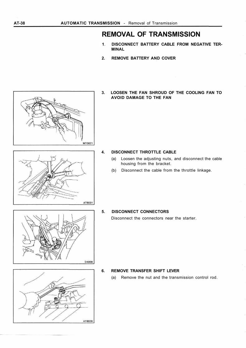
REMOVAL OF TRANSMISSION1. DISCONNECT BATTERY CABLE FROM NEGATIVE TER-
MINAL
2. REMOVE BATTERY AND COVER
3. LOOSEN THE FAN SHROUD OF THE COOLING FAN TOAVOID DAMAGE TO THE FAN
4. DISCONNECT THROTTLE CABLE(a) Loosen the adjusting nuts, and disconnect the cable
housing from the bracket.(b) Disconnect the cable from the throttle linkage.
5. DISCONNECT CONNECTORSDisconnect the connectors near the starter.
6. REMOVE TRANSFER SHIFT LEVER(a) Remove the nut and the transmission control rod.
AUTOMATIC TRANSMISSION - Removal of Transmission AT-39
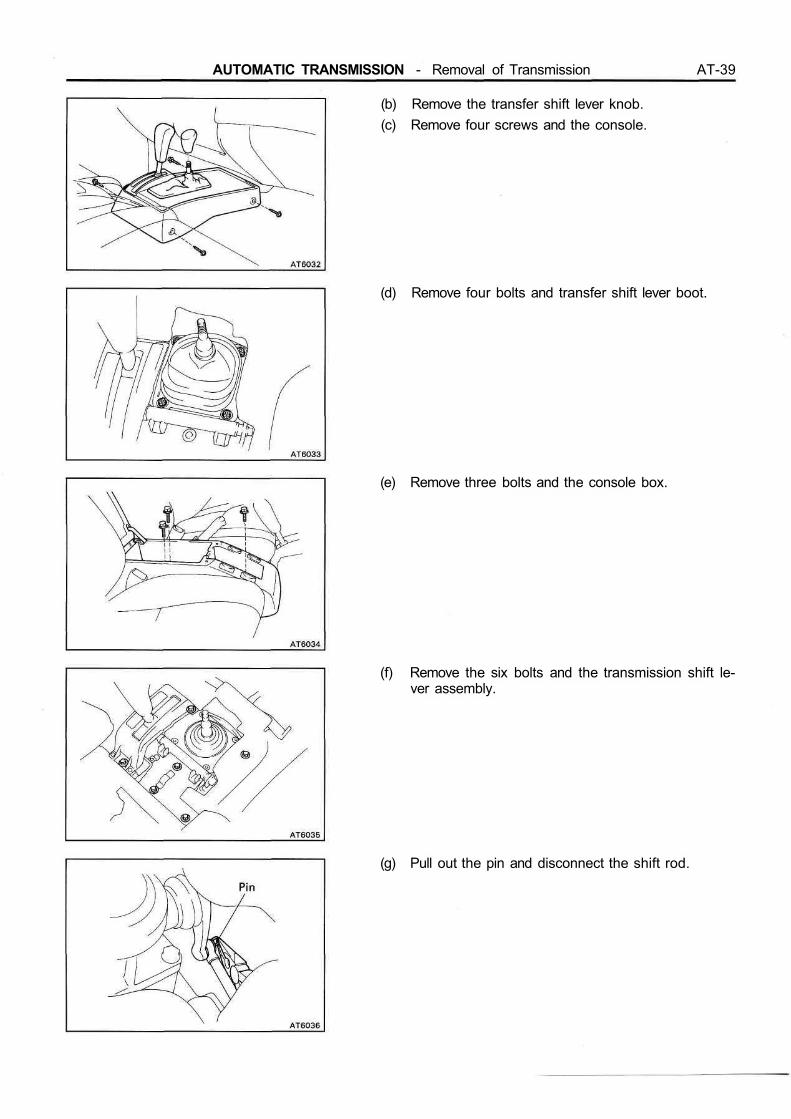
(b) Remove the transfer shift lever knob.(c) Remove four screws and the console.
(d) Remove four bolts and transfer shift lever boot.
(e) Remove three bolts and the console box.
(f) Remove the six bolts and the transmission shift le-ver assembly.
(g) Pull out the pin and disconnect the shift rod.
AT-40 AUTOMATIC TRANSMISSION - Removal of Transmission
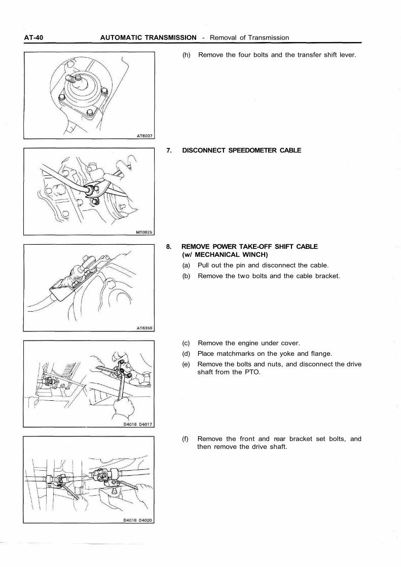
(h) Remove the four bolts and the transfer shift lever.
7. DISCONNECT SPEEDOMETER CABLE
8. REMOVE POWER TAKE-OFF SHIFT CABLE(w/ MECHANICAL WINCH)(a) Pull out the pin and disconnect the cable.(b) Remove the two bolts and the cable bracket.
(c) Remove the engine under cover.(d) Place matchmarks on the yoke and flange.(e) Remove the bolts and nuts, and disconnect the drive
shaft from the PTO.
(f) Remove the front and rear bracket set bolts, andthen remove the drive shaft.
AUTOMATIC TRANSMISSION - Removal of Transmission AT-41
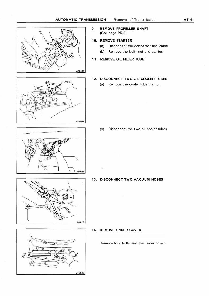
9. REMOVE PROPELLER SHAFT(See page PR-2)
10. REMOVE STARTER(a) Disconnect the connector and cable.(b) Remove the bolt, nut and starter.
11 . REMOVE OIL FILLER TUBE
12. DISCONNECT TWO OIL COOLER TUBES(a) Remove the cooler tube clamp.
(b) Disconnect the two oil cooler tubes.
13. DISCONNECT TWO VACUUM HOSES
14. REMOVE UNDER COVER
Remove four bolts and the under cover.
AT-42 AUTOMATIC TRANSMISSION - Removal of Transmission
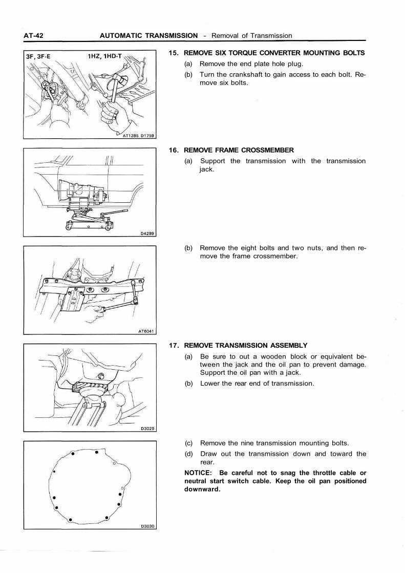
15. REMOVE SIX TORQUE CONVERTER MOUNTING BOLTS(a) Remove the end plate hole plug.(b) Turn the crankshaft to gain access to each bolt. Re-
move six bolts.
16. REMOVE FRAME CROSSMEMBER(a) Support the transmission with the transmission
jack.
(b) Remove the eight bolts and two nuts, and then re-move the frame crossmember.
17. REMOVE TRANSMISSION ASSEMBLY(a) Be sure to out a wooden block or equivalent be-
tween the jack and the oil pan to prevent damage.Support the oil pan with a jack.
(b) Lower the rear end of transmission.
(c) Remove the nine transmission mounting bolts.(d) Draw out the transmission down and toward the
rear.NOTICE: Be careful not to snag the throttle cable orneutral start switch cable. Keep the oil pan positioneddownward.
AUTOMATIC TRANSMISSION - Removal of Transmission AT-43
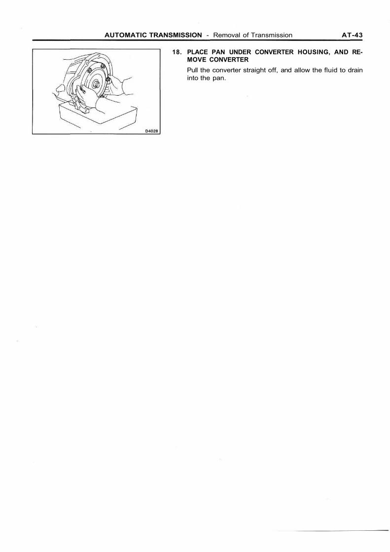
18. PLACE PAN UNDER CONVERTER HOUSING, AND RE-MOVE CONVERTERPull the converter straight off, and allow the fluid to draininto the pan.
AT-44 AUTOMATIC TRANSMISSION - Installation of Transmission
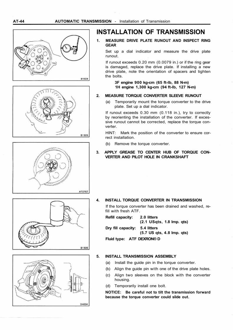
INSTALLATION OF TRANSMISSION1. MEASURE DRIVE PLATE RUNOUT AND INSPECT RING
GEARSet up a dial indicator and measure the drive platerunout.If runout exceeds 0.20 mm (0.0079 in.) or if the ring gearis damaged, replace the drive plate. If installing a newdrive plate, note the orientation of spacers and tightenthe bolts.
3F engine 900 kg-cm (65 ft-lb, 88 N-m)1H engine 1,300 kg-cm (94 ft-lb, 127 N-m)
2. MEASURE TORQUE CONVERTER SLEEVE RUNOUT(a) Temporarily mount the torque converter to the drive
plate. Set up a dial indicator.If runout exceeds 0.30 mm (0.118 in.), try to correctlyby reorienting the installation of the converter. If exces-sive runout cannot be corrected, replace the torque con-verter.HINT: Mark the position of the converter to ensure cor-rect installation.(b) Remove the torque converter.
3. APPLY GREASE TO CENTER HUB OF TORQUE CON-VERTER AND PILOT HOLE IN CRANKSHAFT
4. INSTALL TORQUE CONVERTER IN TRANSMISSIONIf the torque converter has been drained and washed, re-fill with fresh ATF.Refill capacity: 2.0 litters
(2.1 USqts, 1.8 Imp. qts)Dry fill capacity: 5.4 litters
(5.7 US qts, 4.8 Imp. qts)Fluid type: ATF DEXRON® D
5. INSTALL TRANSMISSION ASSEMBLY(a) Install the guide pin in the torque converter.(b) Align the guide pin with one of the drive plate holes.(c) Align two sleeves on the block with the converter
housing.(d) Temporarily install one bolt.NOTICE: Be careful not to tilt the transmission forwardbecause the torque converter could slide out.

AUTOMATIC TRANSMISSION - Installation of Transmission AT-45
(e) Install the nine transmission mounting bolts.Torque: 8 mm bolt 185 kg-cm (13 ft-lb, 18 Nm)
10 mm bolt 380 kg-cm (27 ft-lb, 37 N-m)12 mm bolt 730 kg-cm (53 ft-lb, 72 N-m)
6. INSTALL FRAME CROSSMEMBER(a) Support the transmission with the transmission
jack.
(b) Install the eight bolts and two nuts, and then installthe frame crossmember.
Torque: Bolt 620 kg-cm (45 ft-lb, 61 N-m)Nut 750 kg-cm (54 ft-lb, 74 N-m)
7. INSTALL SIX TORQUE CONVERTER MOUNTING BOLTS(a) Temporarily install each bolts by turning the crank-
shaft.(b) Torque the bolts.Torque: 3F engine 290 kg-cm (21 ft-lb, 28 N-m)
1H engine 550 kg-cm (40 ft-lb, 54 N-m)
8. INSTALL UNDER COVERInstall the under cover with four bolts.

AT-46 AUTOMATIC TRANSMISSION - Installation of Transmission
9. CONNECT TWO VACUUM HOSES
10. CONNECT TWO OIL COOLER TUBES(a) Connect the two oil cooler tubes.Torque: 350 kg-cm (25 ft-lb, 34 N-m)
(b) Install the cooler tube clamp.
11 . INSTALL PROPELLER SHAFT(See page PR-2)
12. INSTALL STARTER(a) Install the bolt, nut and starter.(b) Connect the connector and cable.
13. INSTALL OIL FILLER TUBE
14. CONNECT SPEEDOMETER CABLE
AUTOMATIC TRANSMISSION - Installation of Transmission AT-47
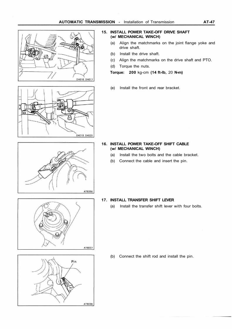
15. INSTALL POWER TAKE-OFF DRIVE SHAFT(w/ MECHANICAL WINCH)(a) Align the matchmarks on the joint flange yoke and
drive shaft.(b) Install the drive shaft.(c) Align the matchmarks on the drive shaft and PTO.(d) Torque the nuts.Torque: 200 kg-cm (14 ft-lb, 20 N-m)
(e) Install the front and rear bracket.
16. INSTALL POWER TAKE-OFF SHIFT CABLE(w/ MECHANICAL WINCH)(a) Install the two bolts and the cable bracket.(b) Connect the cable and insert the pin.
17. INSTALL TRANSFER SHIFT LEVER(a) Install the transfer shift lever with four bolts.
(b) Connect the shift rod and install the pin.

AT-48 AUTOMATIC TRANSMISSION - Installation of Transmission
(c) Install the transmission shift lever assembly with thesix bolts.
(d) Install the console box with three bolts.
(e) Install the transfer shift lever boot with the fourbolts.
(f) Install the console with the four screws.(g) Install the transfer shift lever knob.
(h) Install the transmission control rod with the nut.
AUTOMATIC TRANSMISSION - Installation of Transmission AT-49
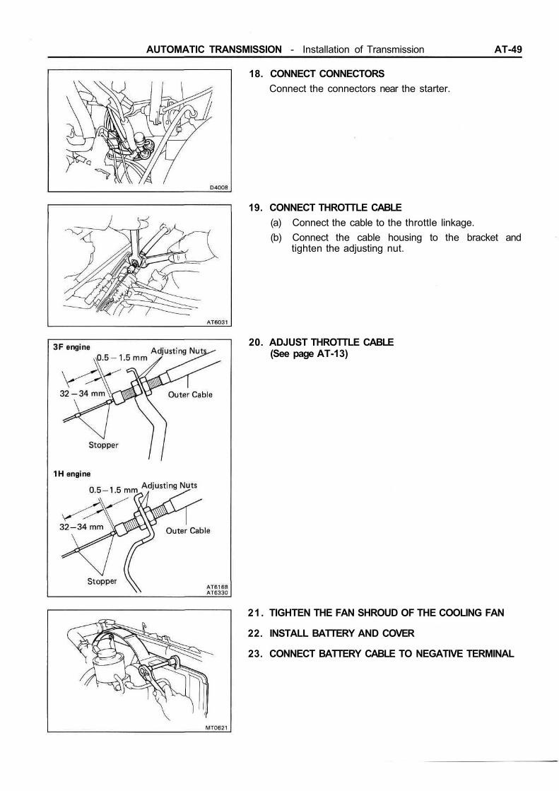
18. CONNECT CONNECTORSConnect the connectors near the starter.
19. CONNECT THROTTLE CABLE(a) Connect the cable to the throttle linkage.(b) Connect the cable housing to the bracket and
tighten the adjusting nut.
20. ADJUST THROTTLE CABLE(See page AT-13)
21. TIGHTEN THE FAN SHROUD OF THE COOLING FAN
22. INSTALL BATTERY AND COVER
23. CONNECT BATTERY CABLE TO NEGATIVE TERMINAL
Related Documents