Aero-Vibro Acoustics For Wind Noise Application David Roche and Ashok Khondge ANSYS, Inc.

Aswc2014 Aerovibro Acoustics Wind Noise
Dec 04, 2015
flow
Welcome message from author
This document is posted to help you gain knowledge. Please leave a comment to let me know what you think about it! Share it to your friends and learn new things together.
Transcript

Aero-Vibro Acoustics For Wind Noise Application
David Roche and Ashok Khondge ANSYS, Inc.
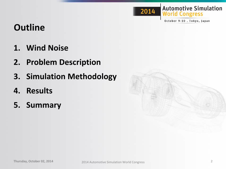
Outline
1. Wind Noise
2. Problem Description
3. Simulation Methodology
4. Results
5. Summary
Thursday, October 02, 2014 2014 Automotive Simulation World Congress 2
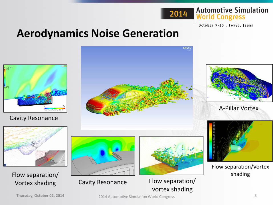
Aerodynamics Noise Generation
Thursday, October 02, 2014 2014 Automotive Simulation World Congress 3
A-Pillar Vortex
Flow separation/Vortex shading
Cavity Resonance Flow separation/ vortex shading
Flow separation/ Vortex shading
Cavity Resonance
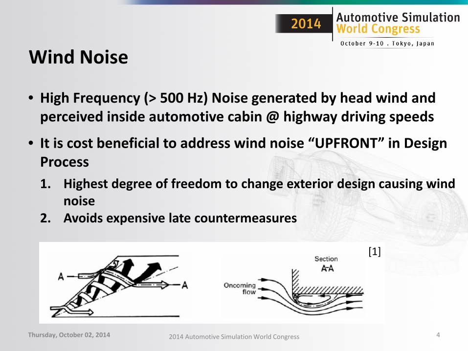
Wind Noise
• High Frequency (> 500 Hz) Noise generated by head wind and perceived inside automotive cabin @ highway driving speeds
• It is cost beneficial to address wind noise “UPFRONT” in Design Process 1. Highest degree of freedom to change exterior design causing wind
noise 2. Avoids expensive late countermeasures
Thursday, October 02, 2014 2014 Automotive Simulation World Congress 4
[1]

Problem Description
• Demonstrate Aero-vibro-acoustics coupling to predict noise at the interior of the Hyundai simplified model [2]
• HSM Model – Simplified model released by Hyundai Kia Motors for 2013 KSNVE Open Benchmark[2]
Thursday, October 02, 2014 2014 Automotive Simulation World Congress 5
Sound Source Transient Separated flow at
A-pillar
Transfer Path [Side glass, windshield]
Receiver Ear of a driver

Simulation Methodology [1]
Thursday, October 02, 2014 2014 Automotive Simulation World Congress 6
A-pillar Mirror Turbulence
Mic.
Glass Interior Walls
Outer Walls (Rigid)
Connection between Vibrating walls and Rigid walls
External CFD Model – Transient Flow
Vibrating Surfaces (Side Glass, Windshield)
Acoustics Model (Car Interior)
Vibroacoustics Modeling
Inflow
CFD modeling

Simulation Methodology [2]
Thursday, October 02, 2014 2014 Automotive Simulation World Congress 7
………
Solve Transient
CFD
Time Freq. domain
transform
Mapping Freq. Domain
Pressure Loading
Solve “Vibro-Acoustics”
Model

Workflow Studied
Thursday, October 02, 2014 2014 Automotive Simulation World Congress 8
ANSYS Fluent Harmonic Strongly
Coupled Vibro-acoustic
ANSYS Fluent Harmonic Structural
Harmonic Acoustic
Pressure Mapping after
FFT
Pressure Mapping after
FFT
Velocity Mapping
Strong Vibroacoustic Coupling
One Way Vibroacoustic Coupling

Test Measurement Points
Thursday, October 02, 2014 2014 Automotive Simulation World Congress 9
650mm
1000mm
200mm
90mm
Interior Microphone Locations
Accelerometers mounted on LH Side
Glass

Transient CFD Modeling
• CFD Domain consists of External HSM surfaces, side glasses and windshield & wind tunnel boundaries
• Configuration Studied : HSM – 0 deg. Yaw – Nozzle Inlet : Velocity Inlet : 130 kmph [Profile] – Tunnel Outlet : Pressure Outlet (Gauge Pressure = 0 Pa) – Tunnel Inlet : Pressure Inlet (Gauge Tot. Pressure = 0 Pa) – Tunnel Top, floor, side, wall BC (No-Slip)
Thursday, October 02, 2014 2014 Automotive Simulation World Congress 10
CFD Domain
Boundary Conditions Inlet Vel. Profile

Mesh Details
Thursday, October 02, 2014 2014 Automotive Simulation World Congress 11
• Total Cell Count = 45 Million • Prims Cell Count = 23 Million • No of Prism Layers = 12 • First Prism Layer Height = 0.05 mm • Surface Mesh Size : A-pillar 1.5 to 2.0 mm,
Side glasses, windshield = 2.0 to 3.0 mm
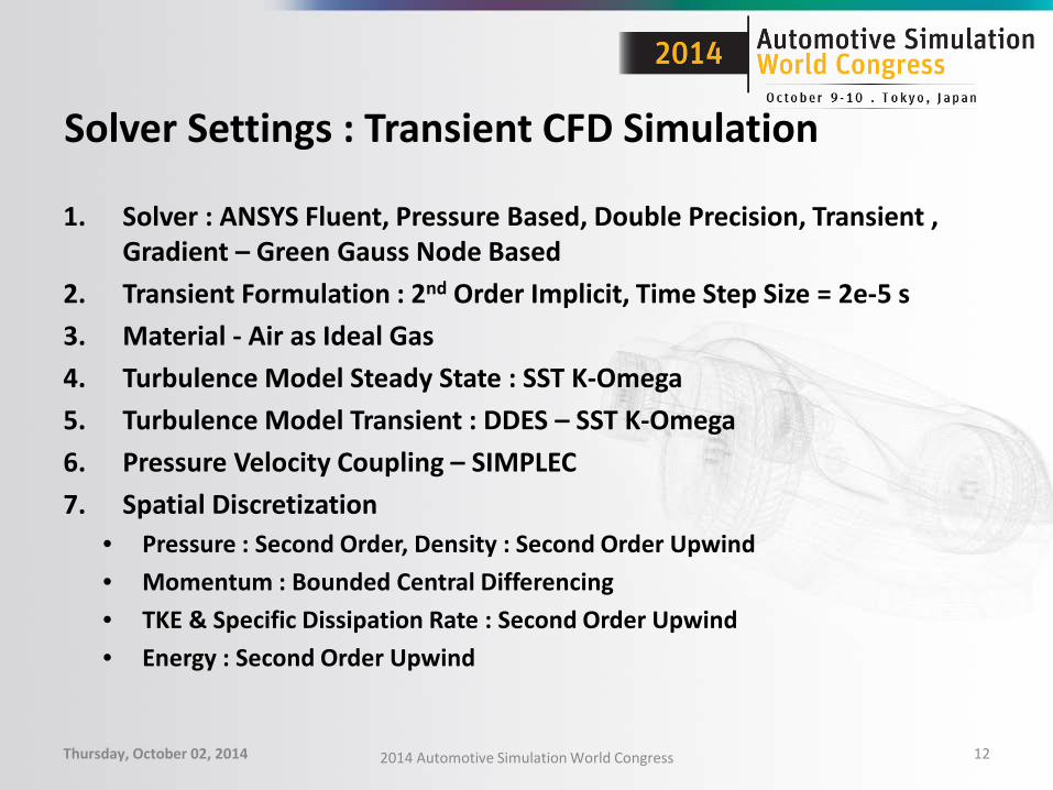
Solver Settings : Transient CFD Simulation
1. Solver : ANSYS Fluent, Pressure Based, Double Precision, Transient , Gradient – Green Gauss Node Based
2. Transient Formulation : 2nd Order Implicit, Time Step Size = 2e-5 s 3. Material - Air as Ideal Gas 4. Turbulence Model Steady State : SST K-Omega 5. Turbulence Model Transient : DDES – SST K-Omega 6. Pressure Velocity Coupling – SIMPLEC 7. Spatial Discretization
• Pressure : Second Order, Density : Second Order Upwind • Momentum : Bounded Central Differencing • TKE & Specific Dissipation Rate : Second Order Upwind • Energy : Second Order Upwind
Thursday, October 02, 2014 2014 Automotive Simulation World Congress 12

Solution Procedure
1. Run Steady State Simulation using SST K-Omega Turbulence Model
2. Steady State Simulation Solver Settings – Pressure Based Coupled Solver
3. Switch to Transient Simulation, Use Second Order Temporal Discretization
4. Switch to DDES SST K-Omega Turbulence Model
5. Run initial transient simulation to achieve dynamic steady state
6. Run Final transient simulation [time step size 2e-5, no. of iterations per time step = 8]
7. Export the ASD Data on Wind-shield, side-glass surfaces at every time step
8. Perform Surface Acoustics FFT to transform source data into Frequency Domain
Thursday, October 02, 2014 2014 Automotive Simulation World Congress 13
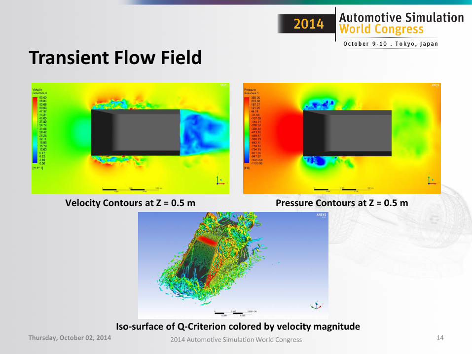
Transient Flow Field
Thursday, October 02, 2014 2014 Automotive Simulation World Congress 14
Velocity Contours at Z = 0.5 m Pressure Contours at Z = 0.5 m
Iso-surface of Q-Criterion colored by velocity magnitude
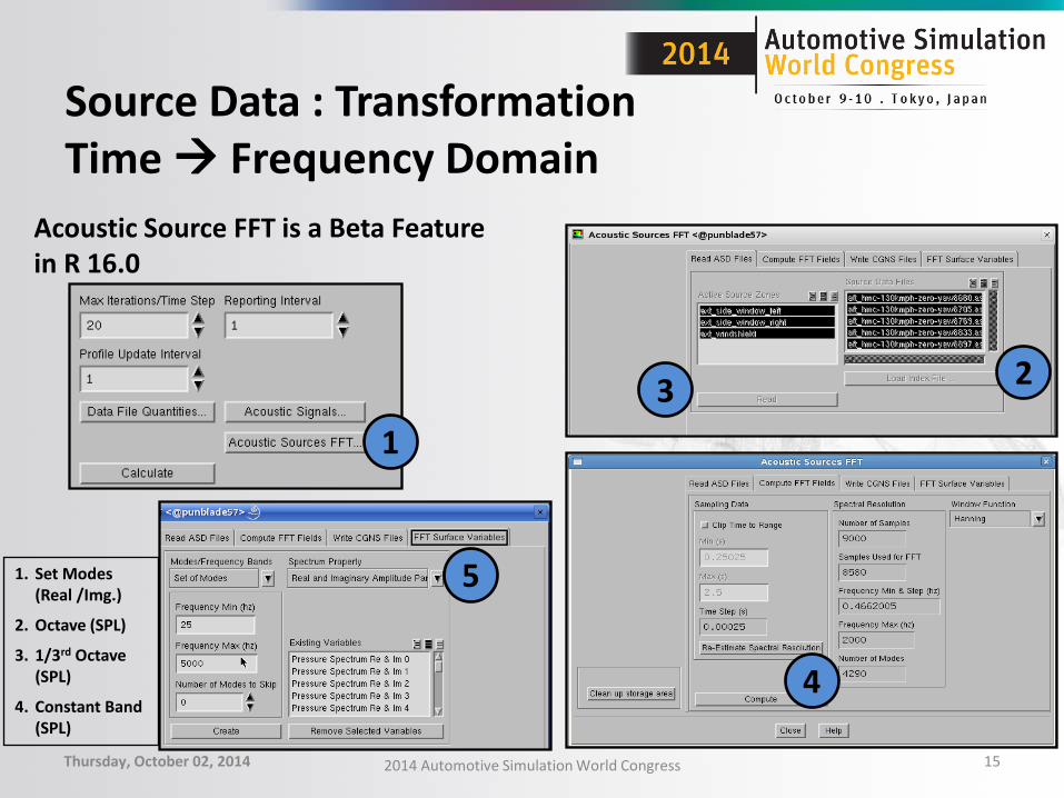
Source Data : Transformation Time Frequency Domain
Thursday, October 02, 2014 2014 Automotive Simulation World Congress 15
1
2 3
4
5
Acoustic Source FFT is a Beta Feature in R 16.0
1. Set Modes (Real /Img.)
2. Octave (SPL)
3. 1/3rd Octave (SPL)
4. Constant Band (SPL)

Surface dB Map
Thursday, October 02, 2014 2014 Automotive Simulation World Congress 16
1/3rd Octave 100 Hz 1/3rd Octave 1000 Hz
1/3rd Octave 500 Hz 1/3rd Octave 1600 Hz

Acoustics Pressure Loading in Freq. Domain
Thursday, October 02, 2014 2014 Automotive Simulation World Congress 17
Freq. 455 Hz Freq. 455 Hz
Freq. 1575 Hz Freq. 1575 Hz

Acoustics Source Mapping
Thursday, October 02, 2014 18
Mapping for 100 Hz ANSYS Fluent ANSYS Mechanical
Mapping for 1000 Hz
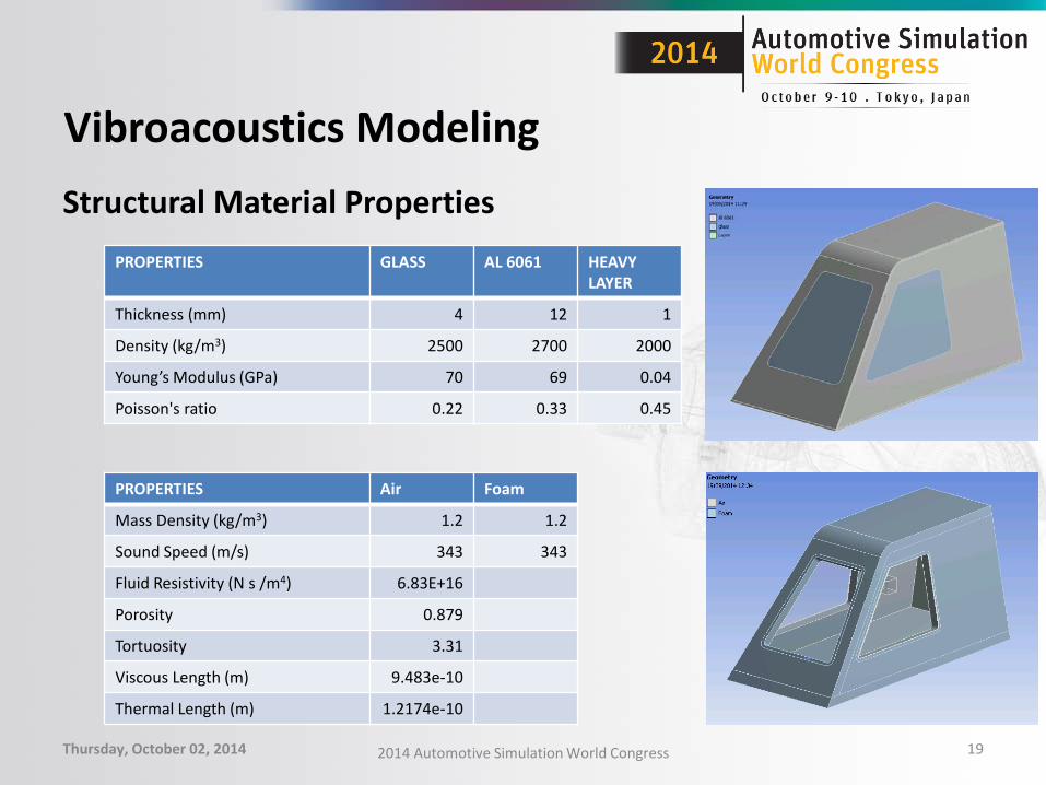
Vibroacoustics Modeling Structural Material Properties
Thursday, October 02, 2014 2014 Automotive Simulation World Congress 19
PROPERTIES GLASS AL 6061 HEAVY LAYER
Thickness (mm) 4 12 1
Density (kg/m3) 2500 2700 2000
Young’s Modulus (GPa) 70 69 0.04
Poisson's ratio 0.22 0.33 0.45
PROPERTIES Air Foam
Mass Density (kg/m3) 1.2 1.2
Sound Speed (m/s) 343 343
Fluid Resistivity (N s /m4) 6.83E+16
Porosity 0.879
Tortuosity 3.31
Viscous Length (m) 9.483e-10
Thermal Length (m) 1.2174e-10

Vibroacoustics Modeling
Strong Coupling: • Full Vibroacoustics harmonic analysis
from 50 to 1000 Hz (117 frequencies) Weak Coupling: • Full structural harmonic analysis from
50 to 1000 Hz (117 frequencies) • Full acoustic harmonic analysis from
50 to 1000 Hz (117 frequencies)
Thursday, October 02, 2014 2014 Automotive Simulation World Congress 20

Results : Acceleration vs Frequency
Thursday, October 02, 2014 2014 Automotive Simulation World Congress 21

Results : SPL(dB) vs 1/3rd Octave Freq. @ Interior Microphone
Thursday, October 02, 2014 2014 Automotive Simulation World Congress 22

Summary
1. Aero and Vibroacoustics coupling is demonstrated using transient CFD and Vibroacoustics modeling
2. ANSYS Fluent solver is used for transient aeroacoustics simulation 3. A Vibroacoustics simulation is done using ANSYS Mechanical using two
approaches – Strong Vibroacoustics coupling approach – Weak Vibroacoustics coupling approach
4. Simulation Results are fairly in good agreement with Test Data 5. Differences between strong and weak Vibroacoustics coupling are
observed – It doesn’t seem possible to neglected the effects of the acoustics cavity on the
deformation of the structure
Thursday, October 02, 2014 2014 Automotive Simulation World Congress 23
Related Documents