Astronomy 101 Name(s): Lab 4: The optics of telescopes (part one) Optics is the field of physics involved in the study of light. No less a luminary than Isaac Newton is credited with originating the field, though of course humans have been interested in the properties of light since antiquity. Newton, in his book Opticks (1704), systematically set out to describe light and its properties; many of the experiments he describes in the book are still the basis of various modern telescopes and spectroscopes. Fundamentally, diffuse rays of starlight are “collected” by mirrors or lenses, and focussed into a viewable, magnified image. In order to focus, the paths of the starlight rays must be changed. Mirrors accomplish this by reflecting the light rays off of a polished curved surface; lenses accomplish the change by bending (or, technically, refracting) the light rays through a curved piece of glass. Some terminology: if the curved surface bows outward, it is called convex; if it bows inward, it is called concave. If both sides of a lens bow outward, it is called a double convex lens; this is the type you will be using. In this exercise, you will first study factors that influence how “good” a telescope is, then draw the paths of starlight through some sample lenses and mirrors, and finally perform various experiments to determine the magnification available through telescopic lenses. Part 1 — Mostly about refractors Aperture size Basically, the primary mirror or lens of a telescope or spectroscope is the surface that will gather the rays of light from distant objects. Clearly, the larger the surface, the more light rays it can gather and thus the more light intensity will be available to view. For this reason, the primary is often called “the light bucket”. On the next page is a figure from an anatomy and physiology textbook that shows the changes in the human eye’s pupil size at varying light conditions. The pupil is the round spot in the middle of the eye. Though the pictures enlarge the size of the eye, by taking a ratio of the dim light pupil to the bright light pupil, we can determine the change in light gathering capability of the eye. 1. Using a ruler, measure the diameter of the dim light and bright light pupil; enter the information in the table on the next page. Calculate the ratio of dim to bright diameter. Assuming that pupils are circular (reasonably good assumption), calculate the area of the dim light and bright light pupils, and enter the data in the table. Hint: A = pr 2 . Calculate the ratio of dim to bright area.

Welcome message from author
This document is posted to help you gain knowledge. Please leave a comment to let me know what you think about it! Share it to your friends and learn new things together.
Transcript
Astronomy 101 Name(s):
Lab 4: The optics of telescopes (part one) Optics is the field of physics involved in the study of light. No less a luminary than Isaac Newton is credited with originating the field, though of course humans have been interested in the properties of light since antiquity. Newton, in his book Opticks (1704), systematically set out to describe light and its properties; many of the experiments he describes in the book are still the basis of various modern telescopes and spectroscopes. Fundamentally, diffuse rays of starlight are “collected” by mirrors or lenses, and focussed into a viewable, magnified image. In order to focus, the paths of the starlight rays must be changed. Mirrors accomplish this by reflecting the light rays off of a polished curved surface; lenses accomplish the change by bending (or, technically, refracting) the light rays through a curved piece of glass. Some terminology: if the curved surface bows outward, it is called convex; if it bows inward, it is called concave. If both sides of a lens bow outward, it is called a double convex lens; this is the type you will be using. In this exercise, you will first study factors that influence how “good” a telescope is, then draw the paths of starlight through some sample lenses and mirrors, and finally perform various experiments to determine the magnification available through telescopic lenses. Part 1 — Mostly about refractors Aperture size Basically, the primary mirror or lens of a telescope or spectroscope is the surface that will gather the rays of light from distant objects. Clearly, the larger the surface, the more light rays it can gather and thus the more light intensity will be available to view. For this reason, the primary is often called “the light bucket”. On the next page is a figure from an anatomy and physiology textbook that shows the changes in the human eye’s pupil size at varying light conditions. The pupil is the round spot in the middle of the eye. Though the pictures enlarge the size of the eye, by taking a ratio of the dim light pupil to the bright light pupil, we can determine the change in light gathering capability of the eye. 1. Using a ruler, measure the diameter of the dim light and bright light pupil; enter the information in the table on the next page. Calculate the ratio of dim to bright diameter. Assuming that pupils are circular (reasonably good assumption), calculate the area of the dim light and bright light pupils, and enter the data in the table. Hint: A = pr2. Calculate the ratio of dim to bright area.

Pupil Dim light Bright light Dim/bright ratio Diameter (mm)
Area (mm2)
2. The area of a light-gathering surface is proportional to its light-gathering capability; what is the mathematical relationship between the linear diameter of a light-gathering surface and its light-gathering capability? 3. Obviously, telescope lenses and mirrors cannot change size (well, some can by opening and shutting an aperture, but its maximum size cannot change). Using the calipers and handling the lenses very carefully, measure the diameter of lenses A, B and C that you will using later in this experiment. Then, using the same formula above, calculate the light-gathering area of each. Lens A B C Diameter (mm)
Area (mm2)
4. Given that you have only these three lenses, which lens should be your primary lens?
Resolution 5. What is the difference between magnification and resolution in a telescope? (Hint: magnification is a unitless number and resolution is measured in degrees, arcminutes or arcseconds) A simple equation to determine the resolution of a telescope is:
q ª 2.5 ¥ 105 lD
Ê Ë
ˆ ¯
where l is the wavelength of incident light in meters, D is the diameter of the objective lens or mirror of the telescope in meters, and q is the angular resolution in arcseconds. 6. For the telescope you will set up in the next part, assume we are viewing a green light (l = 550 nm). Measure the diameter of the primary lens (the one you chose in question 4) and determine the angular resolution of your “telescope”. 7. Will you be able to see individual lunar craters (about 5 arcseconds wide) with this telescope? 8. Give two ways in which you could make the angular resolution better. Hint: one of the ways is impossible using glass lenses. 9. Why don't telescope makers simply fabricate huge objective lenses, instead of trying to make huge polished mirrors? In fact, this is the reason that all the big telescopes in the world are reflectors and not refractors. (Hint: Consider the material lenses are generally made from and the deformation properties of such material)
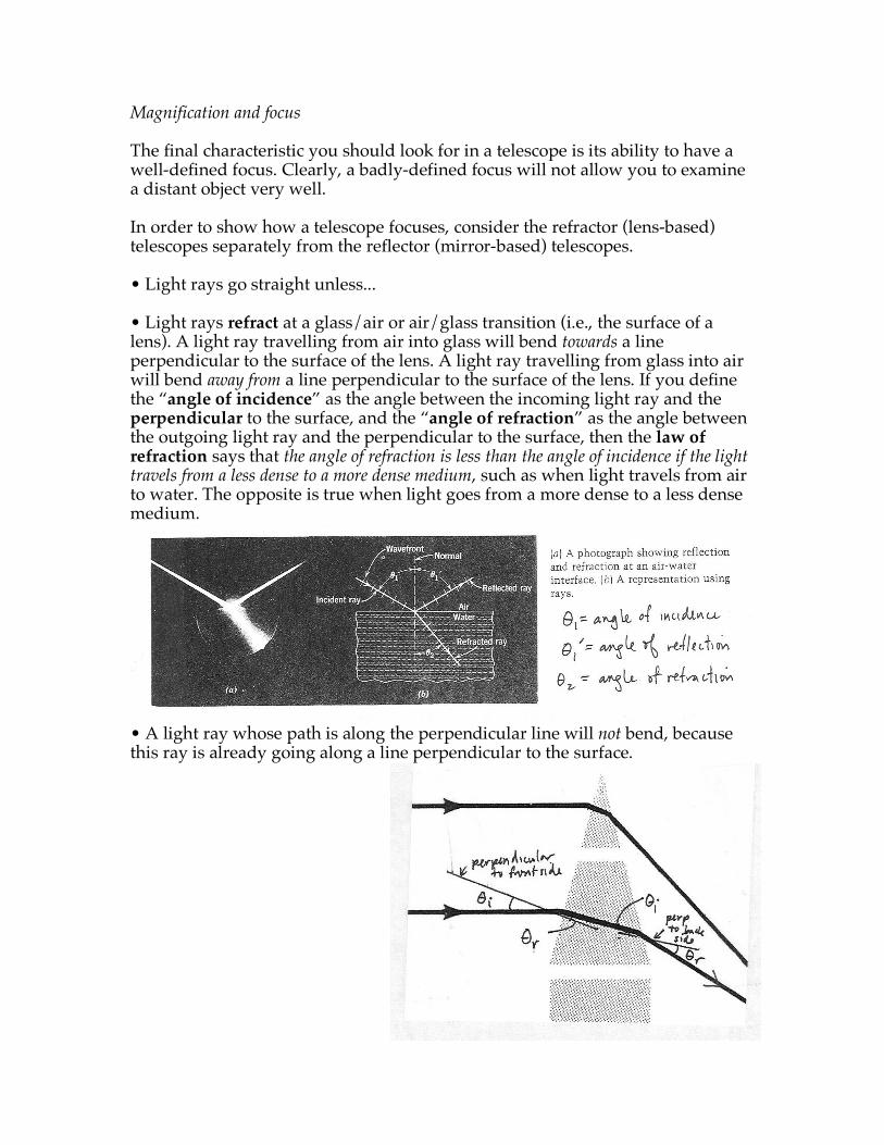
Magnification and focus The final characteristic you should look for in a telescope is its ability to have a well-defined focus. Clearly, a badly-defined focus will not allow you to examine a distant object very well. In order to show how a telescope focuses, consider the refractor (lens-based) telescopes separately from the reflector (mirror-based) telescopes. • Light rays go straight unless... • Light rays refract at a glass/air or air/glass transition (i.e., the surface of a lens). A light ray travelling from air into glass will bend towards a line perpendicular to the surface of the lens. A light ray travelling from glass into air will bend away from a line perpendicular to the surface of the lens. If you define the “angle of incidence” as the angle between the incoming light ray and the perpendicular to the surface, and the “angle of refraction” as the angle between the outgoing light ray and the perpendicular to the surface, then the law of refraction says that the angle of refraction is less than the angle of incidence if the light travels from a less dense to a more dense medium, such as when light travels from air to water. The opposite is true when light goes from a more dense to a less dense medium.
• A light ray whose path is along the perpendicular line will not bend, because this ray is already going along a line perpendicular to the surface.
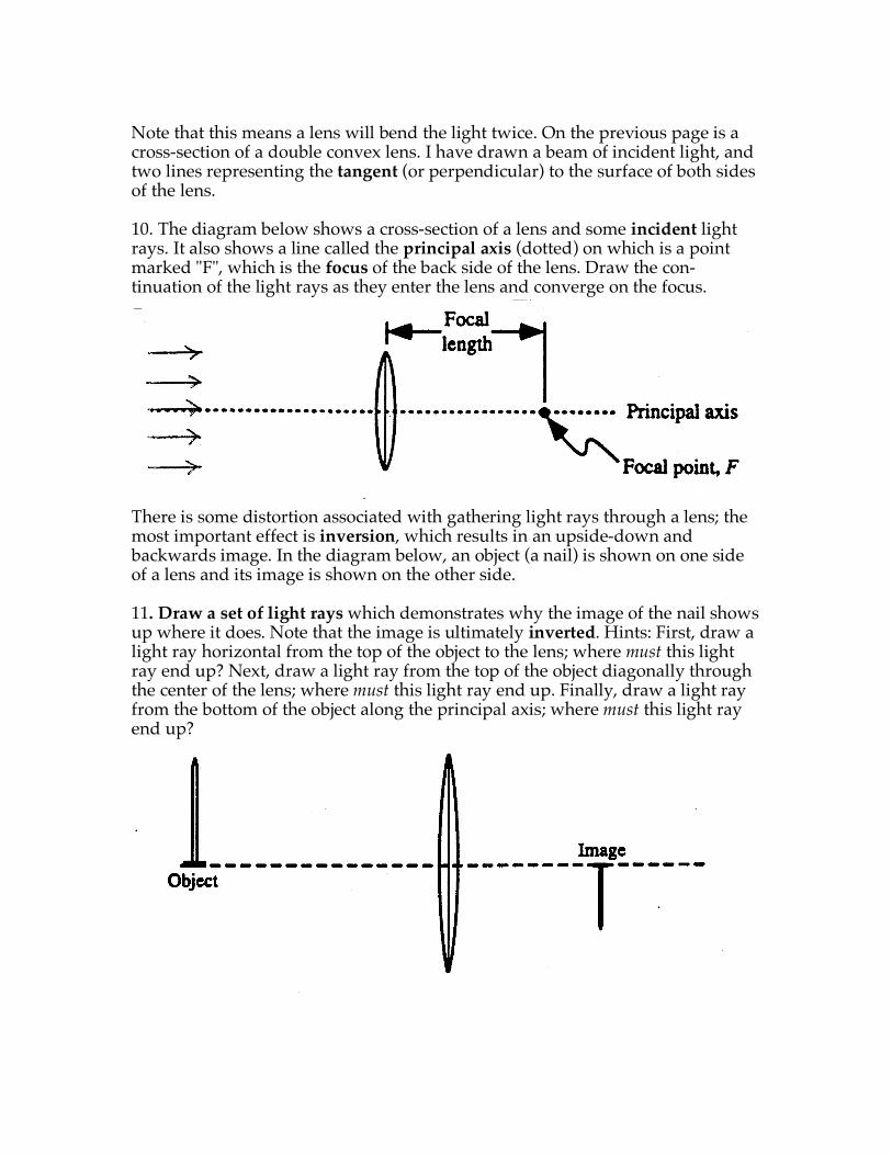
Note that this means a lens will bend the light twice. On the previous page is a cross-section of a double convex lens. I have drawn a beam of incident light, and two lines representing the tangent (or perpendicular) to the surface of both sides of the lens. 10. The diagram below shows a cross-section of a lens and some incident light rays. It also shows a line called the principal axis (dotted) on which is a point marked "F", which is the focus of the back side of the lens. Draw the con-tinuation of the light rays as they enter the lens and converge on the focus.
There is some distortion associated with gathering light rays through a lens; the most important effect is inversion, which results in an upside-down and backwards image. In the diagram below, an object (a nail) is shown on one side of a lens and its image is shown on the other side. 11. Draw a set of light rays which demonstrates why the image of the nail shows up where it does. Note that the image is ultimately inverted. Hints: First, draw a light ray horizontal from the top of the object to the lens; where must this light ray end up? Next, draw a light ray from the top of the object diagonally through the center of the lens; where must this light ray end up. Finally, draw a light ray from the bottom of the object along the principal axis; where must this light ray end up?
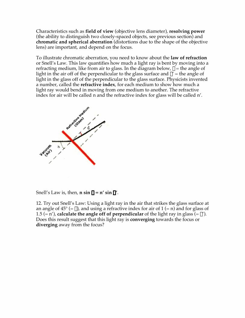
Characteristics such as field of view (objective lens diameter), resolving power (the ability to distinguish two closely-spaced objects, see previous section) and chromatic and spherical aberration (distortions due to the shape of the objective lens) are important, and depend on the focus. To illustrate chromatic aberration, you need to know about the law of refraction or Snell’s Law. This law quantifies how much a light ray is bent by moving into a refracting medium, like from air to glass. In the diagram below, q = the angle of light in the air off of the perpendicular to the glass surface and q’ = the angle of light in the glass off of the perpendicular to the glass surface. Physicists invented a number, called the refractive index, for each medium to show how much a light ray would bend in moving from one medium to another. The refractive index for air will be called n and the refractive index for glass will be called n’.
Snell’s Law is, then, n sin q = n’ sin q’. 12. Try out Snell’s Law: Using a light ray in the air that strikes the glass surface at an angle of 45° (= q), and using a refractive index for air of 1 (= n) and for glass of 1.5 (= n’), calculate the angle off of perpendicular of the light ray in glass (= q’). Does this result suggest that this light ray is converging towards the focus or diverging away from the focus?
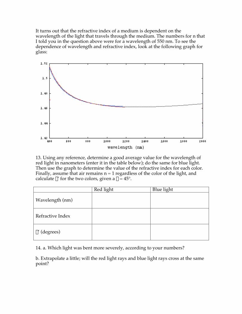
It turns out that the refractive index of a medium is dependent on the wavelength of the light that travels through the medium. The numbers for n that I told you in the question above were for a wavelength of 550 nm. To see the dependence of wavelength and refractive index, look at the following graph for glass:
13. Using any reference, determine a good average value for the wavelength of red light in nanometers (enter it in the table below); do the same for blue light. Then use the graph to determine the value of the refractive index for each color. Finally, assume that air remains n = 1 regardless of the color of the light, and calculate q’ for the two colors, given a q = 45°. Red light Blue light Wavelength (nm)
Refractive Index
q’ (degrees)
14. a. Which light was bent more severely, according to your numbers? b. Extrapolate a little; will the red light rays and blue light rays cross at the same point?
c. On the diagram on the next page (which is the same one from question 10), assume that each light ray is made of two colors, red and blue (it helps if you have color pens or pencils) Draw each of the light rays to their focus(es).
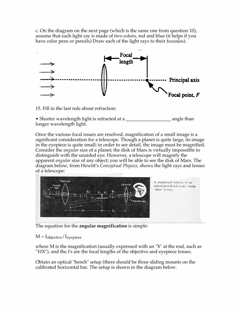
15. Fill in the last rule about refraction: • Shorter wavelength light is refracted at a ___________________ angle than longer wavelength light. Once the various focal issues are resolved, magnification of a small image is a significant consideration for a telescope. Though a planet is quite large, its image in the eyepiece is quite small; in order to see detail, the image must be magnified. Consider the angular size of a planet; the disk of Mars is virtually impossible to distinguish with the unaided eye. However, a telescope will magnify the apparent angular size of any object; you will be able to see the disk of Mars. The diagram below, from Hewitt’s Conceptual Physics, shows the light rays and lenses of a telescope:
The equation for the angular magnification is simple: M = fobjective/feyepiece where M is the magnification (usually expressed with an "X" at the end, such as "10X"), and the f's are the focal lengths of the objective and eyepiece lenses. Obtain an optical "bench" setup (there should be three sliding mounts on the calibrated horizontal bar. The setup is shown in the diagram below.
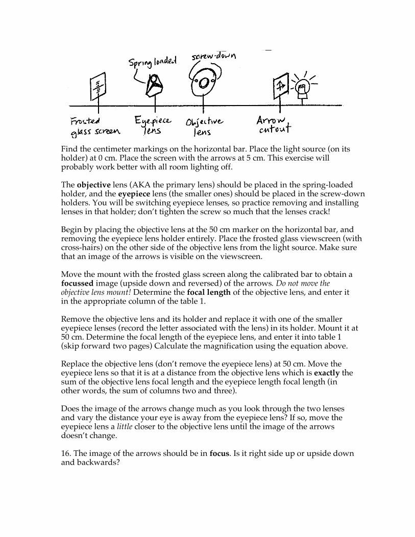
Find the centimeter markings on the horizontal bar. Place the light source (on its holder) at 0 cm. Place the screen with the arrows at 5 cm. This exercise will probably work better with all room lighting off. The objective lens (AKA the primary lens) should be placed in the spring-loaded holder, and the eyepiece lens (the smaller ones) should be placed in the screw-down holders. You will be switching eyepiece lenses, so practice removing and installing lenses in that holder; don’t tighten the screw so much that the lenses crack! Begin by placing the objective lens at the 50 cm marker on the horizontal bar, and removing the eyepiece lens holder entirely. Place the frosted glass viewscreen (with cross-hairs) on the other side of the objective lens from the light source. Make sure that an image of the arrows is visible on the viewscreen. Move the mount with the frosted glass screen along the calibrated bar to obtain a focussed image (upside down and reversed) of the arrows. Do not move the objective lens mount! Determine the focal length of the objective lens, and enter it in the appropriate column of the table 1. Remove the objective lens and its holder and replace it with one of the smaller eyepiece lenses (record the letter associated with the lens) in its holder. Mount it at 50 cm. Determine the focal length of the eyepiece lens, and enter it into table 1 (skip forward two pages) Calculate the magnification using the equation above. Replace the objective lens (don’t remove the eyepiece lens) at 50 cm. Move the eyepiece lens so that it is at a distance from the objective lens which is exactly the sum of the objective lens focal length and the eyepiece length focal length (in other words, the sum of columns two and three). Does the image of the arrows change much as you look through the two lenses and vary the distance your eye is away from the eyepiece lens? If so, move the eyepiece lens a little closer to the objective lens until the image of the arrows doesn’t change. 16. The image of the arrows should be in focus. Is it right side up or upside down and backwards?

17. If one lens inverts the image, why doesn’t the second image invert the inversion and give you the right side up image again? (Note: this will affect which way you should swivel the telescope when tracking an astronomical object) (Further note: Draw two lenses and light rays in order to visualize this) 18. In order to quantify magnification, obtain a laptop computer and a video camera. A. Turn on the computer and wait for it to go through all of its start-up procedures. Eventually, you should get a standard Windows desktop. B. From the video camera kit, take out the camera and slide on the battery pack. C. Remove the lens cap and turn the thumbwheel on the back of the camera to “Camera”. Make sure there is some battery life left. (Open the side screen if that is more comfortable for you). If the battery is low, attach the AC adapter cord to an electric plug and a plug on the camera body, below the battery (remove the cover). D. Insert the digital video tape. It is important at this step not to force any part of the camera. FLIP THE SWITCH ON THE SIDE OF THE CAMERA TO “TAPE”. Make sure the tape is fully rewound. E. Make sure the camera is held as steadily as possible and sight the image of the crossed arrows in the eyepiece lens; center it as much as possible. Then sight the crossed arrows not through the eyepiece lens but at the same distance away from the crossed arrow holder. F. With the camera on pause and looking at the crossed arrows through the eyepiece, push the “photo” button down halfway and wait for a beep; then push the button down all the way to take a still picture. The camera will take six seconds to record the picture; hold the camera still. G. Take another photo at the same distance from the arrows, this time not looking through the eyepiece. H. Turn the thumbwheel on the back of the camera to “Play”. Attach the Firewire (silver) cord between the camera’s DV in/out port (under a bluish cover on the front of the camera) and the computer’s Firewire port (on the left side of the laptop). The Firewire is directional so don’t force one end to fit into a given port; try the other end. I. On the computer, start up Windows Movie Maker by clicking Start Æ Programs Æ Accessories Æ Windows Movie Maker.

J. On the menu on the left side of Windows Movie Maker, click on “Capture from video device”. Choose a file name that you will remember and click “Next”. K. Click the radio button for “Digital Device Format” (this is AVI format) and click “Next”. L. Click the radio button for “Capture entire video automatically” and wait for your whole video to play. Make sure that “Create Clips when Wizard Finishes” is checked. Click “Stop Capture” when it is done. M. In the Collections window of Movie Maker, click on one of the photos (it should be one of the “clips”) to display them in the large window to the right. N. Using a ruler, measure the length of one of the arrows in the image. Use millimeters. Record this in the data table below. O. Repeat the measurement with the second of the two photos; be sure to use the exact same arrow or the exact same part of the arrow. P. Repeat the previous steps for the other eyepiece lens. Q. Turn off the camera, use the “Safely Remove Hardware” program (lower right set of icons on tool bar), then disconnect it from the laptop. R. Put away all of the equipment. Don’t forget to shut down running programs on the laptop and to turn it off before placing it on the cart. S. Using the measured values, calculate the measured magnification (this is as easy as it sounds). Table 1 — Data for determining the magnification of several eyepieces Lens (letter)
fobjective (cm)
feyepiece (cm)
Calculated magnification
Apparent size of image
Apparentsize of object
Measured magnification
19. What general rule(s) can you formulate about the focal length of the objective lens, the focal length of the eyepiece lens and higher magnification? 20. Examine the eyepiece lenses from actual telescopes; what do you notice is the drawback to the simple rule of “get a smaller focal length eyepiece”?
Related Documents