ASTi SYNAPSE Radio-IP Operator Manual Document: DOC-01-SYN4B-OM-1 Advanced Simulation Technology inc. 500A Huntmar Park Drive, Herndon, Virginia, 20170 USA Revision F (Feb., 2012)

Welcome message from author
This document is posted to help you gain knowledge. Please leave a comment to let me know what you think about it! Share it to your friends and learn new things together.
Transcript
ASTi SYNAPSERadio-IP
Operator Manual
Document: DOC-01-SYN4B-OM-1
Advanced Simulation Technology inc. 500A Huntmar Park Drive, Herndon, Virginia, 20170 USARevision F (Feb., 2012)

Product Name: ASTi Synapse
Description: Radio-IP Bridge
Part No.:
SYN-RT-
Number Comm Nets:04: 4 Nets08: 8 Nets16: 16 Nets
ASTi Synapse Radio-IP Operator Manual
© Copyright ASTi 2012. ASTi documents are continuously updated see www.asti-usa.com/support/document.
Restricted Rights: Use, duplication, or disclosure by the Government is subject to restrictions as set forth in sub-paragraph (c)(1)(ii) of the Rights in Technical Data and Computer Software clause at DFARS 252.227-7013.
This material may be reproduced by or for the U.S. Government pursuant to the copyright license under the clause at DFARS 252.227-7013 (1994).
ASTi
500-A Huntmar Park Drive
Herndon, VA 20170

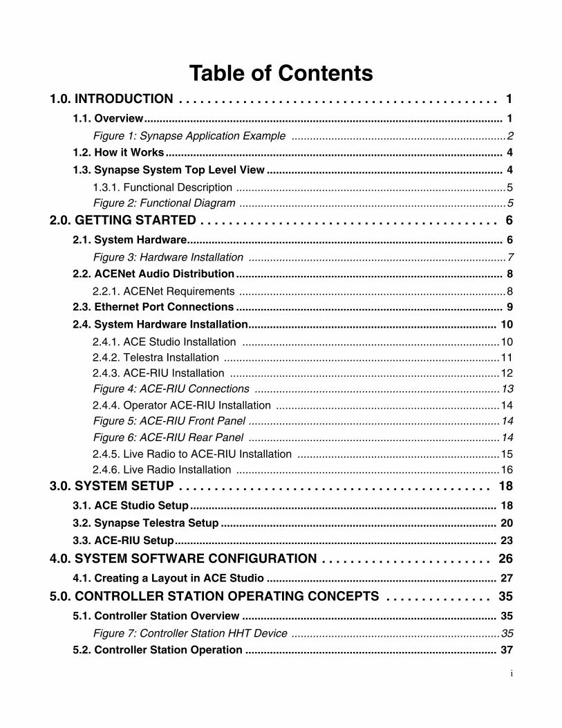
Table of Contents1.0. INTRODUCTION . . . . . . . . . . . . . . . . . . . . . . . . . . . . . . . . . . . . . . . . . . . . . 1
1.1. Overview..................................................................................................................... 1
Figure 1: Synapse Application Example ......................................................................2
1.2. How it Works .............................................................................................................. 4
1.3. Synapse System Top Level View ............................................................................. 4
1.3.1. Functional Description ........................................................................................5Figure 2: Functional Diagram .......................................................................................5
2.0. GETTING STARTED . . . . . . . . . . . . . . . . . . . . . . . . . . . . . . . . . . . . . . . . . . 62.1. System Hardware....................................................................................................... 6
Figure 3: Hardware Installation ....................................................................................7
2.2. ACENet Audio Distribution ....................................................................................... 8
2.2.1. ACENet Requirements .......................................................................................82.3. Ethernet Port Connections ....................................................................................... 9
2.4. System Hardware Installation................................................................................. 10
2.4.1. ACE Studio Installation ....................................................................................102.4.2. Telestra Installation ..........................................................................................112.4.3. ACE-RIU Installation ........................................................................................12Figure 4: ACE-RIU Connections ................................................................................13
2.4.4. Operator ACE-RIU Installation .........................................................................14Figure 5: ACE-RIU Front Panel ..................................................................................14
Figure 6: ACE-RIU Rear Panel ..................................................................................14
2.4.5. Live Radio to ACE-RIU Installation ..................................................................152.4.6. Live Radio Installation ......................................................................................16
3.0. SYSTEM SETUP . . . . . . . . . . . . . . . . . . . . . . . . . . . . . . . . . . . . . . . . . . . . 183.1. ACE Studio Setup .................................................................................................... 18
3.2. Synapse Telestra Setup .......................................................................................... 20
3.3. ACE-RIU Setup......................................................................................................... 23
4.0. SYSTEM SOFTWARE CONFIGURATION . . . . . . . . . . . . . . . . . . . . . . . . 264.1. Creating a Layout in ACE Studio ........................................................................... 27
5.0. CONTROLLER STATION OPERATING CONCEPTS . . . . . . . . . . . . . . . 355.1. Controller Station Overview ................................................................................... 35
Figure 7: Controller Station HHT Device ....................................................................35
5.2. Controller Station Operation .................................................................................. 37
i
APPENDIX A: SYNAPSE ACE-RIU TECHNICAL SPECS . . . . . . . . . . . . . . . 39General Information........................................................................................................ 39
Connector Information ................................................................................................40Power Supply .............................................................................................................40
APPENDIX B: COLD START . . . . . . . . . . . . . . . . . . . . . . . . . . . . . . . . . . . . . . 41
APPENDIX C: SAFETY AND HANDLING . . . . . . . . . . . . . . . . . . . . . . . . . . . . 42
APPENDIX D: WARRANTY AND CUSTOMER SUPPORT. . . . . . . . . . . . . . . 43Warranty .......................................................................................................................... 43
Repairs and Returns....................................................................................................... 43
APPENDIX E: FURTHER READING . . . . . . . . . . . . . . . . . . . . . . . . . . . . . . . . 44
ii
ASTi Synapse Bridge Operator Manual (Ver. 1, Rev. F)
1.0. INTRODUCTION1.1. Overview
Synapse Radio-IP Bridge (“Synapse Bridge”) is a digital voice communications system that routes live radio voice traffic between multiple sites over local and wide area data networks, pro-viding a wealth of capabilities, including:
• Extend live radio communications through the data network. Example: Link aircraft radios in Nevada to tank radios in Germany.
• Realize inter-communications between disparate live radio systems. Example: PRC-117 in AM mode is bridged to PRC-119 in FM mode.
• Integrate Synapse Bridge with Synapse Workstation or ASTi PC’ver to link operators with shared live radio assets, conserving live radio usage. Example: Synapse Workstation operators at USAF Ops Center and PC’ver operators at Exercise Control intercommunicate with live aircraft and tank radios.
• Integrate voice comms for live-virtual training exercises. Example: Live aircraft in Nevada communicates with Special Forces flight simulator.
• Remotely command and control the ASTi Synapse Bridge over the network. Example: ASTi ACE Studio and Remote Management System (RMS) software at Exercise Control is used to configure, monitor and manage Synapse Bridges and Workstations.
Copyright © 2012 Advanced Simulation Technology inc. 1

ASTi Synapse Bridge Operator Manual (Ver. 1, Rev. F)
Here is a notional diagram of an application example for an ASTi Synapse Radio Bridging Sys-tem. Two Synapse Bridges are integrated with Synapse Workstations and an ACE Studio master control station. Synapse systems can inter-communicate with existing ASTi DACS systems, as well as ASTi PC’ver.
IP
Communication
Network
U.S. Navy, Analysis Cell
Joint Forces, Exercise Control
Studio
USAF, Special Ops Squadron
USMC, Live Fire Range
Live SINCGARS
Telestra Integrated
with Flight Simulator
Synapse Operator Server
Synapse Radio-IP BridgeSynapse Workstation
Live RF CommsIP Network CommsRemote Monitor & ManagementACENet, Digital Audio & Remote Radio Control
Features Voisus Clients, hosted on customer-furnished Linux or Windows PC
IPNetwork
US Army, Task Force HQ
Exercise Planner & MonitorRemote Mgmt. System (RMS)Simulated Radio App (optional)
Figure 1: Synapse Application Example
2 Copyright © 2012 Advanced Simulation Technology inc.
ASTi Synapse Bridge Operator Manual (Ver. 1, Rev. F)
Synapse Bridge integrates live and simulated voice communications from an array of sources into a unified network, providing a balance of simplicity and flexibility to facilitate installation and management of communications for networked exercises.
Synapse Bridge features:
• Flexible and Scalable Architecture: Configure Bridge modules to meet custom require-ments.
• Interoperable: Inter-operates with full fidelity radio simulations.
• Deployable out-of-the-box: Connect, configure, operate.
• DIS/ HLA Compliant: Synapse is inter-operable with a vast array of simulators, data anal-ysis and data logging tools.
• Simple to Install: Modular/ click-together, all-Ethernet installation.
• Simple to Run: Even novice users can exploit the capabilities of ASTi’s powerful and intu-itive ACE software.
• Robust and Reliable: Industrial hardware, Intel Quad Core CPU, Realtime Linux OS.
Copyright © 2012 Advanced Simulation Technology inc. 3
ASTi Synapse Bridge Operator Manual (Ver. 1, Rev. F)
1.2. How it Works
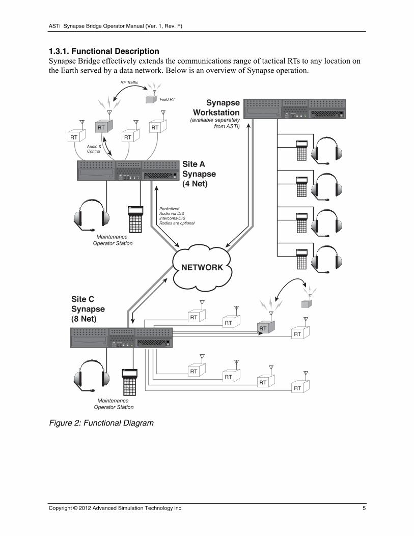
Base station radio transceivers (RTs) receive audio over-the-air from field RTs. Analog audio streams from the base station RTs are interfaced to a Synapse Bridge, which digitizes and formats the audio streams into DIS network radio* packets.
*Note: Base model Synapse Bridge employs DIS network intercoms as the voice transport mech-anism, which provides a simple, clear communications solution. Synapse Bridge is also available with optional DIS simulated radios, which provide communications compatibility with full fidel-ity radio simulations. For clarity, this document generally refers to “DIS radios” when discussing network voice communications.
DIS radios are transported over long-haul networks, where they are received by other Synapse Bridges. These remote Synapse Bridges re-generate the analog audio streams and pass it to base station RTs for over-the-air transmission into the field.
1.3. Synapse System Top Level View
An RT is connected to a Synapse via baseband audio mic and speaker lines. (This connection is actually made through an interface module, called an ACE-RIU. For clarity, the top level diagram does not show ACE-RIUs).
This RT receives voice traffic over-the-air from locally installed RTs. The resulting baseband audio is passed to the Synapse for digitization, compression and packetization. Each RT voice stream is associated with a DIS radio, which is assigned a specific, virtual frequency.
The Synapse transfers the compressed data packets via DIS radios over a lossless IP network to a remote Synapse. Note that there may be many Synapse system residing on the network and each one can receive and process the digitized RT transmission.
On the remote Synapse, a DIS radio tuned to a matching frequency-receives the network trans-mission. Synapse then decompresses and decodes the data packets producing an analog audio stream.
The voice stream is distributed to the RT connected to each of the remote Synapse systems. The Synapse automatically keys the remote RT's push-to-talk (PTT) switch to transmit the audio infor-mation, over the air, to one or more RTs installed at the remote site.
Each of the DIS radios can be thought of as a virtual RT net that extends across the data network, linking all Base RTs associated with a specific radio frequency.
For the sake of clarity only one RT communication net is described, however each Synapse sys-tem can simultaneously process many independent RT nets.
4 Copyright © 2012 Advanced Simulation Technology inc.
ASTi Synapse Bridge Operator Manual (Ver. 1, Rev. F)
1.3.1. Functional DescriptionSynapse Bridge effectively extends the communications range of tactical RTs to any location on the Earth served by a data network. Below is an overview of Synapse operation.
1 2
+
–
3
4 5 6
7 8
0
9
PTT
Vol
BusF1
F2
Duplex
SideTone
TalkListen
VOXPTT
Shift Test ENTER
RT
RT RT
RT
1 2
+
–
3
4 5 6
7 8
0
9
PTT
Vol
BusF1
F2
Duplex
SideTone
TalkListen
VOXPTT
Shift Test ENTER
RTRT
RTRT
RTRT
RTRT
1 2
+
–
3
4 5 6
7 8
0
9
PTT
Vol
BusF1
F2
Duplex
SideTone
TalkListen
VOXPTT
Shift Test ENTER
1 2
+
–
3
4 5 6
7 8
0
9
PTT
Vol
BusF1
F2
Duplex
SideTone
TalkListen
VOXPTT
Shift Test ENTER
1 2
+
–
3
4 5 6
7 8
0
9
PTT
Vol
BusF1
F2
Duplex
SideTone
TalkListen
VOXPTT
Shift Test ENTER
1 2
+
–
3
4 5 6
7 8
0
9
PTT
Vol
BusF1
F2
Duplex
SideTone
TalkListen
VOXPTT
Shift Test ENTER
Site ASynapse (4 Net)
Site CSynapse(8 Net)
SynapseWorkstation
(available separatelyfrom ASTi)
RF Traffic
Field RT
Audio &Control
Maintenance Operator Station
Maintenance Operator Station
NETWORK
Figure 2: Functional Diagram
Copyright © 2012 Advanced Simulation Technology inc. 5

ASTi Synapse Bridge Operator Manual (Ver. 1, Rev. F)
2.0. GETTING STARTED2.1. System Hardware
The Synapse Bridge includes the following components.
Description SYN-RT-04 SYN-RT-08 SYN-RT-16
Telestra 1 1 1
ACE-RIU, Standard 1 1 1
ACE-RIU, labeled “Radio ACE-RIU”
1 2 4
Live Radio Adapter Cables 4 8 16
Maintenance Operator Station set: HHT, headset and cable
1 1 1
6 Copyright © 2012 Advanced Simulation Technology inc.
ASTi Synapse Bridge Operator Manual (Ver. 1, Rev. F)
Telestra
ACENet Compatible Ethernet Switch
ACE Studio(See Note)
Advanced Simulation Technology, Inc.
CHAN A CHAN B CHAN C CHAN D
RIU1
DISACENetAnalog Voice / PTTSerial Data
Advanced Simulation Technology, Inc.
CHAN A CHAN B CHAN C CHAN D
RIU2
Maintenance Operator
DISNetwork
1CMSC
2* 3SYNC
FREQ
4DATA
5 6ERF
OFST
7CHG
8 9LOUT 000
TIME
CLR 0LOAD
STO BATTCALL
HUBLOWSIG
ANT
RXMT
RF PWR
LO
LOM HI
PA
HUB
CHAN
MANCUE
12 3
45
6
MODE
SCFH
FH-M
SQON OFF
LDTST
STBY
FCTNOFF
Z-FH
REMRXMT
DIM•
••
•
•
COMSEC
PTCT TD RV
Z
VOL WHSP
•
• •
• •
•
FILL
DATA
AUDIO
1CMSC
2* 3SYNC
FREQ
4DATA
5 6ERF
OFST
7CHG
8 9LOUT 000
TIME
CLR 0LOAD
STO BATTCALL
HUBLOWSIG
ANT
RXMT
RF PWR
LO
LOM HI
PA
HUB
CHAN
MANCUE
12 3
45
6
MODE
SCFH
FH-M
SQON OFF
LDTST
STBY
FCTNOFF
Z-FH
REMRXMT
DIM•
••
•
•
COMSEC
PTCT TD RV
Z
VOL WHSP
•
• •
• •
•
FILL
DATA
AUDIO
1CMSC
2* 3SYNC
FREQ
4DATA
5 6ERF
OFST
7CHG
8 9LOUT 000
TIME
CLR 0LOAD
STO BATTCALL
HUBLOWSIG
ANT
RXMT
RF PWR
LO
LOM HI
PA
HUB
CHAN
MANCUE
12 3
45
6
MODE
SCFH
FH-M
SQON OFF
LDTST
STBY
FCTNOFF
Z-FH
REMRXMT
DIM•
••
•
•
COMSEC
PTCT TD RV
Z
VOL WHSP
•
• •
• •
•
FILL
DATA
AUDIO
1CMSC
2* 3SYNC
FREQ
4DATA
5 6ERF
OFST
7CHG
8 9LOUT 000
TIME
CLR 0LOAD
STO BATTCALL
HUBLOWSIG
ANT
RXMT
RF PWR
LO
LOM HI
PA
HUB
CHAN
MANCUE
12 3
45
6
MODE
SCFH
FH-M
SQON OFF
LDTST
STBY
FCTNOFF
Z-FH
REMRXMT
DIM•
••
•
•
COMSEC
PTCT TD RV
Z
VOL WHSP
•
• •
• •
•
FILL
DATA
AUDIO
“ACE-RIUs”(standard)
“Radio ACE-RIUs”
To Other ASTi Communication Systems
Cable
Headset
Live RadioAdapter Cables
Eth0
Eth1
Live radios are customer furnished.
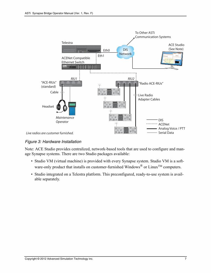
Figure 3: Hardware Installation
Note: ACE Studio provides centralized, network-based tools that are used to configure and man-age Synapse systems. There are two Studio packages available:
• Studio VM (virtual machine) is provided with every Synapse system. Studio VM is a soft-
ware-only product that installs on customer-furnished Windows® or LinuxTM computers.
• Studio integrated on a Telestra platform. This preconfigured, ready-to-use system is avail-able separately.
Copyright © 2012 Advanced Simulation Technology inc. 7
ASTi Synapse Bridge Operator Manual (Ver. 1, Rev. F)
2.2. ACENet Audio Distribution
The ACENet network provides a low latency, networked-based audio and I/O distribution archi-tecture. ACE-RIUs connect to the ACENet network via an Ethernet port on the back panel of the device using a Category 5 cable. The Category 5 cable connects to an ACENet approved Ethernet switch. The maximum cable length is 100 meters (328 feet). The Ethernet switch connects to the Synapse system via a Category 5 cable. The maximum cable length is 100 meters (328 feet).
Note: ACE-RIUs do not support daisy chaining to additional units or internal switching across networks.
Caution: Homemade cables are the number one reason for product performance prob-lems. ASTi highly recommends using only manufactured, commercial, premium grade cable.
2.2.1. ACENet RequirementsIn order to achieve a working ACENet infrastructure users must adhere to certain core require-ments such as a closed network. No other traffic should be present on the ACENet network. Con-nect only Synapse Telestras, ACE-RIUs, and ACENet compatible equipment to the network.
All ACENet capable devices must adhere to the following cabling requirements:
• CAT 5e cable or better
• 100 meters (328 feet) maximum distance
• Wire according to 1000 BASE-T Specifications
Guidance for advanced ACENet configurations:
IMPORTANT: Synapse Workstation and Synapse Radio Bridge products require that each indi-vidual system (comprised of a single Telestra platform and a number of ACE-RIUs) be intercon-nected on its own ACENet. Conversely, you cannot connect multiple Telestras and ACE-RIUs on a common ACENet.
• An Ethernet switch is required for ACENet (no routers or hubs).
• Configure ACENet using multiple switches to realize flexible installations. Maximum of 6 hops (5 switches) are accommodated.
• 1Gb operation is required for ACENet
• Only port-based VLANs are acceptable.
• Each VLAN port must not see traffic from the other ports.
• If using VLANS: place each Telestra and its associated ACE-RIUs on a separate VLAN.
• VLAN tagging is not supported.
• Advanced protocols such as: 802.1p, port priority, spanning tree, etc. are not supported.
• Telestra platform can connect directly to an ACE-RIU using crossover CAT5e cable.
• See the ACENet User Guide (DOC-01-TEL4-AN-UG-1) for more information. See the ASTi website for the most recent versions of documentation. (www.asti-usa.com/support)
8 Copyright © 2012 Advanced Simulation Technology inc.

ASTi Synapse Bridge Operator Manual (Ver. 1, Rev. F)
2.3. Ethernet Port Connections
Port Connection
Eth0 DIS (network with ACE Studio)
Eth1 ACENet (network with ACENet devices)
Eth2 N/A
PROPERTY OF
ASTI0000
Network PortsSee chassis labels for ethernet assignment
Ethernet labels will be Eth0, Eth1, and Eth2
Please read the Eth0, Eth1, and Eth2 labels on your system to verify the Ethernet locations.
Copyright © 2012 Advanced Simulation Technology inc. 9
ASTi Synapse Bridge Operator Manual (Ver. 1, Rev. F)
2.4. System Hardware Installation
Refer to Figure 3 for top level system installation guidance and the Figure 4 for ACENet and ACE-RIU installation details.
2.4.1. ACE Studio InstallationIn addition to the ACE Studio platform, you will need the following items:
• Monitor
• Keyboard
• Mouse
• Power Supply
• CAT5 or CAT6 cable
• Network connection
Follow these steps to install the ACE Studio platform:
1. Connect to a monitor, keyboard and mouse.
2. Connect ethernet port to an IP network (common with all of the Synapse Telestra systems that will be remotely managed by the ACE Studio).
3. Connect to power.
10 Copyright © 2012 Advanced Simulation Technology inc.
ASTi Synapse Bridge Operator Manual (Ver. 1, Rev. F)
2.4.2. Telestra InstallationIn addition to the Telestra chassis, you will need the following items:
• Monitor
• Keyboard
• Power cord
• CAT5 or CAT6 cable
• Network connection
Follow these steps to install the Telestra platform:
1. Connect Telestra platform to a monitor and keyboard. Note that a monitor and keyboard are only necessary for initial software configuration.
2. Connect Eth0 Ethernet port to an IP network (common with other Synapse Telestra sys-tems and the ACE Studio that will remotely managing the Telestra).
3. Connect Eth1 Ethernet port to the Ethernet switch. This is the starting point for the ACENet network that connects the Telestra to the ACE-RIUs. See section 2.2 for detailed ACENet guidance.
4. Connect to power.
Copyright © 2012 Advanced Simulation Technology inc. 11
ASTi Synapse Bridge Operator Manual (Ver. 1, Rev. F)
2.4.3. ACE-RIU InstallationIn addition to the ACE-RIUs, you will need the following items:
• ACE-RIU Power Supply
• CAT5 or CAT6 cable
• Ethernet switch
Synapse Radio Bridge includes two ACE-RIU configurations.
Description: Maintenance Operator ACE-RIU
Label: "ACE-RIU"
Quantity: One
Use: Connect to the furnished headset cable and headset and handheld terminal (HHT)
Description: Live Radio ACE-RIU
Label: “Radio ACE-RIU”
Quantity: (1) for SYN-RT-04, (2) for SYN-RT-08, (4) for SYN-RT-16
Use: Connect to the furnished live radio cables and live radios (customer furnished). Each ACE-RIU connects to up to four live radios.
NOTE: For more ACE-RIU information see Appendix A “Synapse ACE-RIU Technical Specs.”
12 Copyright © 2012 Advanced Simulation Technology inc.

ASTi Synapse Bridge Operator Manual (Ver. 1, Rev. F)
Refer to the figure below for ACE-RIU installation:
Advanced Simulation Technology, Inc.
CHAN A CHAN B CHAN C CHAN D
RIU1
Advanced Simulation Technology, Inc.
CHAN A CHAN B CHAN C CHAN D
RIU2
Maintenance Operator
1CMSC
2* 3SYNC
FREQ
4DATA
5 6ERF
OFST
7CHG
8 9LOUT 000
TIME
CLR 0LOAD
STO BATTCALL
HUBLOWSIG
ANT
RXMT
RF PWR
LO
LOM HI
PA
HUB
CHAN
MANCUE
12 3
45
6
MODE
SCFH
FH-M
SQON OFF
LDTST
STBY
FCTNOFF
Z-FH
REMRXMT
DIM•
••
•
•
COMSEC
PTCT TD RV
Z
VOL WHSP
•
• •
• •
•
FILL
DATA
AUDIO
1CMSC
2* 3SYNC
FREQ
4DATA
5 6ERF
OFST
7CHG
8 9LOUT 000
TIME
CLR 0LOAD
STO BATTCALL
HUBLOWSIG
ANT
RXMT
RF PWR
LO
LOM HI
PA
HUB
CHAN
MANCUE
12 3
45
6
MODE
SCFH
FH-M
SQON OFF
LDTST
STBY
FCTNOFF
Z-FH
REMRXMT
DIM•
••
•
•
COMSEC
PTCT TD RV
Z
VOL WHSP
•
• •
• •
•
FILL
DATA
AUDIO
1CMSC
2* 3SYNC
FREQ
4DATA
5 6ERF
OFST
7CHG
8 9LOUT 000
TIME
CLR 0LOAD
STO BATTCALL
HUBLOWSIG
ANT
RXMT
RF PWR
LO
LOM HI
PA
HUB
CHAN
MANCUE
12 3
45
6
MODE
SCFH
FH-M
SQON OFF
LDTST
STBY
FCTNOFF
Z-FH
REMRXMT
DIM•
••
•
•
COMSEC
PTCT TD RV
Z
VOL WHSP
•
• •
• •
•
FILL
DATA
AUDIO
1CMSC
2* 3SYNC
FREQ
4DATA
5 6ERF
OFST
7CHG
8 9LOUT 000
TIME
CLR 0LOAD
STO BATTCALL
HUBLOWSIG
ANT
RXMT
RF PWR
LO
LOM HI
PA
HUB
CHAN
MANCUE
12 3
45
6
MODE
SCFH
FH-M
SQON OFF
LDTST
STBY
FCTNOFF
Z-FH
REMRXMT
DIM•
••
•
•
COMSEC
PTCT TD RV
Z
VOL WHSP
•
• •
• •
•
FILL
DATA
AUDIO
*Note each ACE-RIU is named sequentially RIU1- RIU5 in RMS.
To Target, Eth1
Channel A Channel A B C D
Advanced Simulation Technology, Inc.
CHAN A CHAN B CHAN C CHAN D
RIU3
1CMSC
2* 3SYNC
FREQ
4DATA
5 6ERF
OFST
7CHG
8 9LOUT 000
TIME
CLR 0LOAD
STO BATTCALL
HUBLOWSIG
ANT
RXMT
RF PWR
LO
LOM HI
PA
HUB
CHAN
MANCUE
12 3
45
6
MODE
SCFH
FH-M
SQON OFF
LDTST
STBY
FCTNOFF
Z-FH
REMRXMT
DIM•
••
•
•
COMSEC
PTCT TD RV
Z
VOL WHSP
•
• •
• •
•
FILL
DATA
AUDIO
1CMSC
2* 3SYNC
FREQ
4DATA
5 6ERF
OFST
7CHG
8 9LOUT 000
TIME
CLR 0LOAD
STO BATTCALL
HUBLOWSIG
ANT
RXMT
RF PWR
LO
LOM HI
PA
HUB
CHAN
MANCUE
12 3
45
6
MODE
SCFH
FH-M
SQON OFF
LDTST
STBY
FCTNOFF
Z-FH
REMRXMT
DIM•
••
•
•
COMSEC
PTCT TD RV
Z
VOL WHSP
•
• •
• •
•
FILL
DATA
AUDIO
1CMSC
2* 3SYNC
FREQ
4DATA
5 6ERF
OFST
7CHG
8 9LOUT 000
TIME
CLR 0LOAD
STO BATTCALL
HUBLOWSIG
ANT
RXMT
RF PWR
LO
LOM HI
PA
HUB
CHAN
MANCUE
12 3
45
6
MODE
SCFH
FH-M
SQON OFF
LDTST
STBY
FCTNOFF
Z-FH
REMRXMT
DIM•
••
•
•
COMSEC
PTCT TD RV
Z
VOL WHSP
•
• •
• •
•
FILL
DATA
AUDIO
1CMSC
2* 3SYNC
FREQ
4DATA
5 6ERF
OFST
7CHG
8 9LOUT 000
TIME
CLR 0LOAD
STO BATTCALL
HUBLOWSIG
ANT
RXMT
RF PWR
LO
LOM HI
PA
HUB
CHAN
MANCUE
12 3
45
6
MODE
SCFH
FH-M
SQON OFF
LDTST
STBY
FCTNOFF
Z-FH
REMRXMT
DIM•
••
•
•
COMSEC
PTCT TD RV
Z
VOL WHSP
•
• •
• •
•
FILL
DATA
AUDIO
Channel A B C D
ACENet Switch
Figure 4: ACE-RIU Connections
Copyright © 2012 Advanced Simulation Technology inc. 13
ASTi Synapse Bridge Operator Manual (Ver. 1, Rev. F)
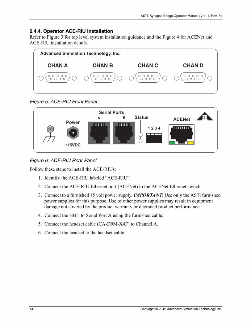
2.4.4. Operator ACE-RIU InstallationRefer to Figure 3 for top level system installation guidance and the Figure 4 for ACENet and ACE-RIU installation details.
Advanced Simulation Technology, Inc.
CHAN A CHAN B CHAN C CHAN D
Figure 5: ACE-RIU Front Panel
Serial Ports
A B Status
Power
+15VDC
1 2 3 4
ACENet
Figure 6: ACE-RIU Rear Panel
Follow these steps to install the ACE-RIUs:
1. Identify the ACE-RIU labeled “ACE-RIU”.
2. Connect the ACE-RIU Ethernet port (ACENet) to the ACENet Ethernet switch.
3. Connect to a furnished 15 volt power supply. IMPORTANT: Use only the ASTi furnished power supplies for this purpose. Use of other power supplies may result in equipment damage not covered by the product warranty or degraded product performance
4. Connect the HHT to Serial Port A using the furnished cable.
5. Connect the headset cable (CA-D9M-X4F) to Channel A.
6. Connect the headset to the headset cable.
14 Copyright © 2012 Advanced Simulation Technology inc.

ASTi Synapse Bridge Operator Manual (Ver. 1, Rev. F)
2.4.5. Live Radio to ACE-RIU InstallationFollow these steps to install the live radios:
1. Identify an ACE-RIU labeled “RADIO ACE-RIU”.
2. Connect the ACE-RIU Ethernet port to the ACENet Ethernet Switch.
3. Connect to a furnished 15 volt power supply. IMPORTANT: Use only the ASTi furnished power supplies for this purpose. Use of other power supplies may result in equipment damage not covered by the product warranty or degraded product performance.
4. Connect a live radio cable (CA-D9M-NC6F) to Channel A. Connect the cable to the live radio handset port. See section 2.5. for live radio installation guidance.
5. Repeat the live radio-to-ACE-RIU connection procedure, up to the capacity of your Syn-apse system.
Here's a summary of the live radio to ACE-RIU connections:
Live Radio RIU Address RIU Channel SYN-RT-04 SYN-RT-08 SYN-RT-16
1 2 A
2 2 B
3 2 C
4 2 D
5 3 A
6 3 B
7 3 C
8 3 D
9 4 A
10 4 B
11 4 C
12 4 D
13 5 A
14 5 B
15 5 C
16 5 D
Note: The gray boxes are the number of live radios per system and highlight the corresponding ACE-RIU address and channels.
Copyright © 2012 Advanced Simulation Technology inc. 15
ASTi Synapse Bridge Operator Manual (Ver. 1, Rev. F)
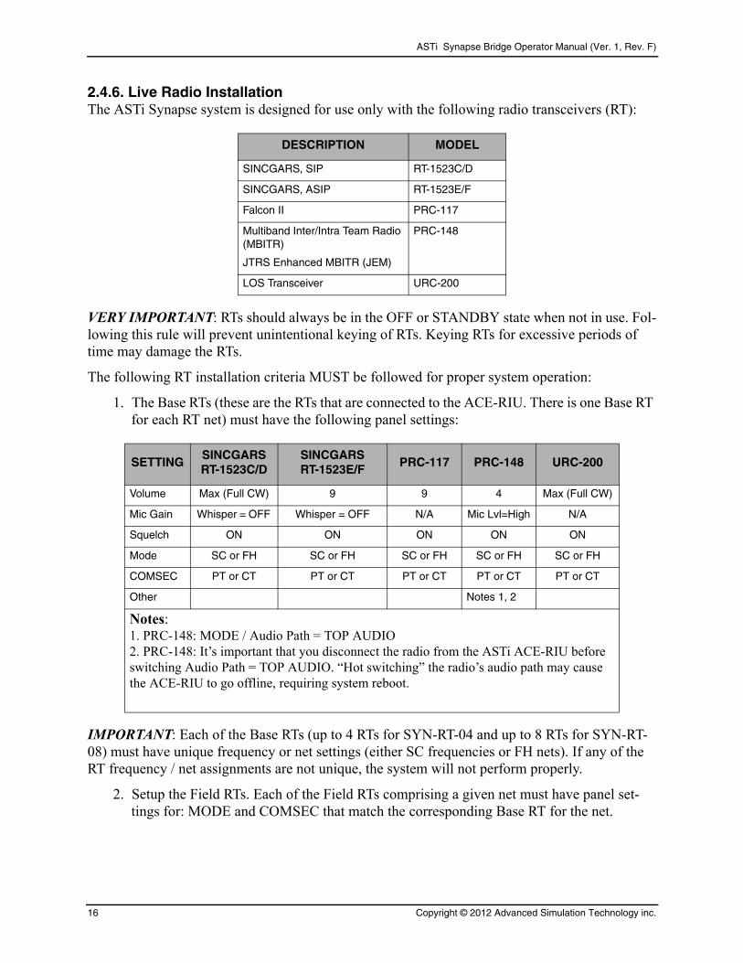
2.4.6. Live Radio InstallationThe ASTi Synapse system is designed for use only with the following radio transceivers (RT):
DESCRIPTION MODEL
SINCGARS, SIP RT-1523C/D
SINCGARS, ASIP RT-1523E/F
Falcon II PRC-117
Multiband Inter/Intra Team Radio (MBITR)
JTRS Enhanced MBITR (JEM)
PRC-148
LOS Transceiver URC-200
VERY IMPORTANT: RTs should always be in the OFF or STANDBY state when not in use. Fol-lowing this rule will prevent unintentional keying of RTs. Keying RTs for excessive periods of time may damage the RTs.
The following RT installation criteria MUST be followed for proper system operation:
1. The Base RTs (these are the RTs that are connected to the ACE-RIU. There is one Base RT for each RT net) must have the following panel settings:
SETTINGSINCGARSRT-1523C/D
SINCGARSRT-1523E/F
PRC-117 PRC-148 URC-200
Volume Max (Full CW) 9 9 4 Max (Full CW)
Mic Gain Whisper = OFF Whisper = OFF N/A Mic Lvl=High N/A
Squelch ON ON ON ON ON
Mode SC or FH SC or FH SC or FH SC or FH SC or FH
COMSEC PT or CT PT or CT PT or CT PT or CT PT or CT
Other Notes 1, 2
Notes:1. PRC-148: MODE / Audio Path = TOP AUDIO2. PRC-148: It’s important that you disconnect the radio from the ASTi ACE-RIU before switching Audio Path = TOP AUDIO. “Hot switching” the radio’s audio path may cause the ACE-RIU to go offline, requiring system reboot.
IMPORTANT: Each of the Base RTs (up to 4 RTs for SYN-RT-04 and up to 8 RTs for SYN-RT-08) must have unique frequency or net settings (either SC frequencies or FH nets). If any of the RT frequency / net assignments are not unique, the system will not perform properly.
2. Setup the Field RTs. Each of the Field RTs comprising a given net must have panel set-tings for: MODE and COMSEC that match the corresponding Base RT for the net.
16 Copyright © 2012 Advanced Simulation Technology inc.

ASTi Synapse Bridge Operator Manual (Ver. 1, Rev. F)
3. If the MODE-FH or COMSEC-CT settings are selected on any of the RT nets, follow proper procedures for loading the FH Data or COMSEC Keys into the Base and Field RTs. Refer to the RT manual for fill procedure details.
VERY IMPORTANT: The Base RTs must be installed so that a high fidelity radio link with remote RTs is established (ideally) using the LOW transmit power setting on the Base RTs.
4. The Base RTs may be set to MEDIUM transmit power, but the possibility of Radio Fre-quency Interference (RFI) between the Base RT and the Synapse system is increased. If system malfunctions (such as spurious RT or network transmissions or increased audio noise on the nets) occur, re-establish the Base RT to Remote RT links using LOW power.
Under no circumstances should any of the Base RTs be set to HIGH transmit power - RFI will occur between the RTs and the Synapse system, causing the system to malfunction (spurious transmissions and increased audio noise).
The RT manual states that the planning range for low power, line of sight installations using the standard manpack or vehicle antenna is 200 meters to 400 meters.
These planning ranges may be degraded due to environmental factors.
Use of OE-254 (tower) antennas are highly recommended for increasing ranges, improv-ing RF link fidelity and greatly reducing the chance of RFI.
5. The final step in the RT installation procedure is to perform a standard radio check between each set of Base and Field RTs as part of the system operational checkout:
Copyright © 2012 Advanced Simulation Technology inc. 17

ASTi Synapse Bridge Operator Manual (Ver. 1, Rev. F)
3.0. SYSTEM SETUP
3.1. ACE Studio Setup
ACE Studio provides centralized, network-based tools that are used to configure and manage Synapse systems. There are two Studio packages available:
• Studio VM (virtual machine) is provided with every Synapse system. Studio VM is a soft-
ware-only product that installs on customer-furnished Windows® or LinuxTM computers.
• Studio integrated on a Telestra platform. This preconfigured, ready-to-use system is avail-able separately.
The following instructions apply to both Studio VM and integrated Studio products.
1. Power on ACE Studio and allow it to boot.
2. Log into ACE Studio:
Username: aceuser Password: aceuser
3. In the top left corner select System > Administration > Networks.
18 Copyright © 2012 Advanced Simulation Technology inc.
ASTi Synapse Bridge Operator Manual (Ver. 1, Rev. F)
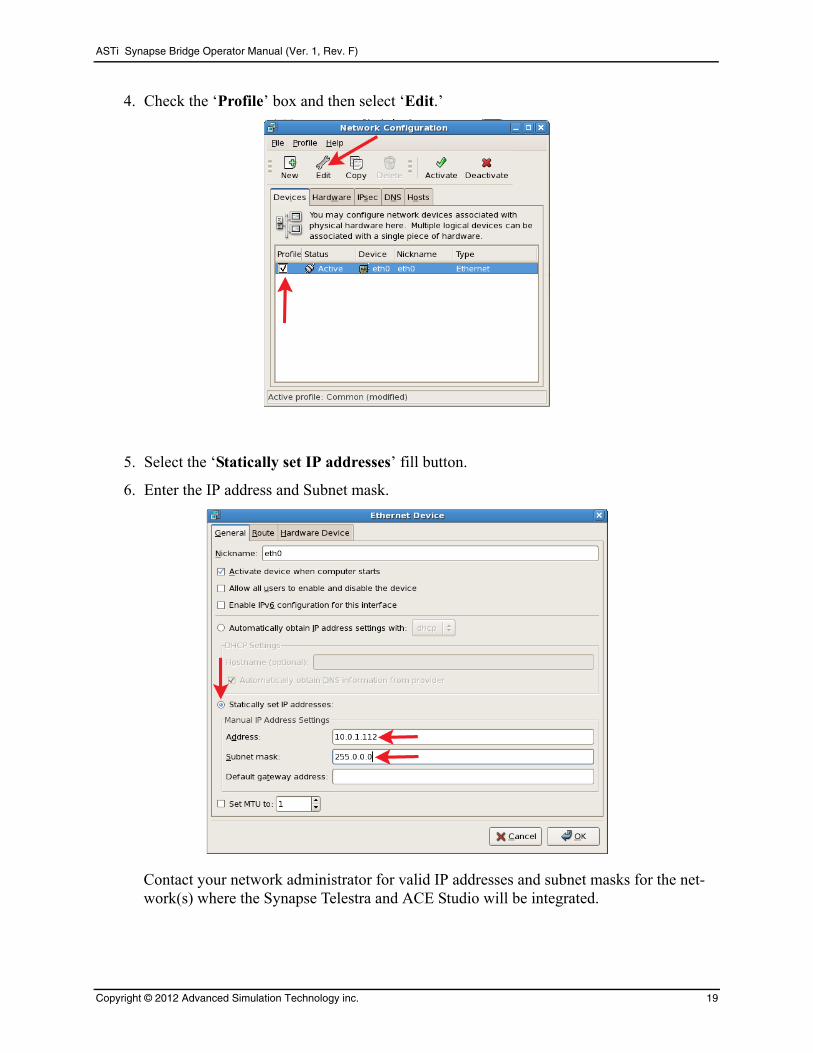
4. Check the ‘Profile’ box and then select ‘Edit.’
5. Select the ‘Statically set IP addresses’ fill button.
6. Enter the IP address and Subnet mask.
Contact your network administrator for valid IP addresses and subnet masks for the net-work(s) where the Synapse Telestra and ACE Studio will be integrated.
Copyright © 2012 Advanced Simulation Technology inc. 19
ASTi Synapse Bridge Operator Manual (Ver. 1, Rev. F)
3.2. Synapse Telestra Setup
1. Power on the Telestra and allow it to boot.
2. Login with
Username: root Password: abcd1234
3. At the prompt type:
ace-net-config -a xxx.xxx.xxx.xxx -n yyy.yyy.yyy.yyy
where “xxx.xxx.xxx.xxx” is the IP address and “yyy.yyy.yyy.yyy” is the net-mask.
This sets the IP address and netmask for Eth0 which is used to access the Remote Man-agement System (RMS) via a browser to complete the network setup.
4. Optional: For more network setup options type:
ace-net-config -h
5. Reboot the Telestra to activate the changes.
Once you have configured the Telestra IP address, you can use ASTi’s web-browser based Remote Management System (RMS) interface to make subsequent changes to the Telestra net-work settings.
20 Copyright © 2012 Advanced Simulation Technology inc.
ASTi Synapse Bridge Operator Manual (Ver. 1, Rev. F)
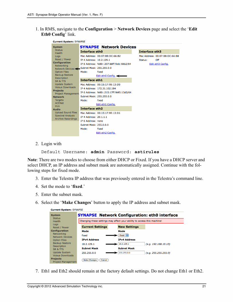
1. In RMS, navigate to the Configuration > Network Devices page and select the ‘Edit Eth0 Config’ link.
2. Login with
Default Username: admin Password: astirules
Note: There are two modes to choose from either DHCP or Fixed. If you have a DHCP server and select DHCP, an IP address and subnet mask are automatically assigned. Continue with the fol-lowing steps for fixed mode.
3. Enter the Telestra IP address that was previously entered in the Telestra’s command line.
4. Set the mode to ‘fixed.’
5. Enter the subnet mask.
6. Select the ‘Make Changes’ button to apply the IP address and subnet mask.
7. Eth1 and Eth2 should remain at the factory default settings. Do not change Eth1 or Eth2.
Copyright © 2012 Advanced Simulation Technology inc. 21

ASTi Synapse Bridge Operator Manual (Ver. 1, Rev. F)
8. Optional: Change the network hostname of the Synapse. Navigate to the Configuration > Networking page, and select the ‘Edit Network Config’ link. Change the hostname and select ‘Make Changes.’
9. Navigate to the ‘System Actions’ page (System > Reset/Power) and select ‘System Reboot.’ The reboot process will take approximately 2 minutes, select the ‘Reboot Teles-tra System Now’ button.
22 Copyright © 2012 Advanced Simulation Technology inc.
ASTi Synapse Bridge Operator Manual (Ver. 1, Rev. F)
3.3. ACE-RIU Setup
1. Power on the ACE-RIU.
2. Using a Category 5 cable connect the Ethernet switch to Eth1 on the Synapse Telestra.
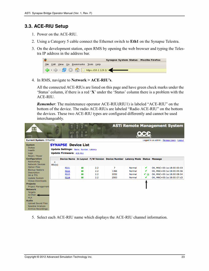
3. On the development station, open RMS by opening the web browser and typing the Teles-tra IP address in the address bar.
4. In RMS, navigate to Network > ACE-RIU’s.
All the connected ACE-RIUs are listed on this page and have green check marks under the ‘Status’ column, if there is a red ‘X’ under the ‘Status’ column there is a problem with the ACE-RIU.
Remember: The maintenance operator ACE-RIU(RIU1) is labeled “ACE-RIU” on the bottom of the device. The radio ACE-RIUs are labeled “Radio ACE-RIU” on the bottom the devices. These two ACE-RIU types are configured differently and cannot be used interchangeably.
5. Select each ACE-RIU name which displays the ACE-RIU channel information.
Copyright © 2012 Advanced Simulation Technology inc. 23
ASTi Synapse Bridge Operator Manual (Ver. 1, Rev. F)
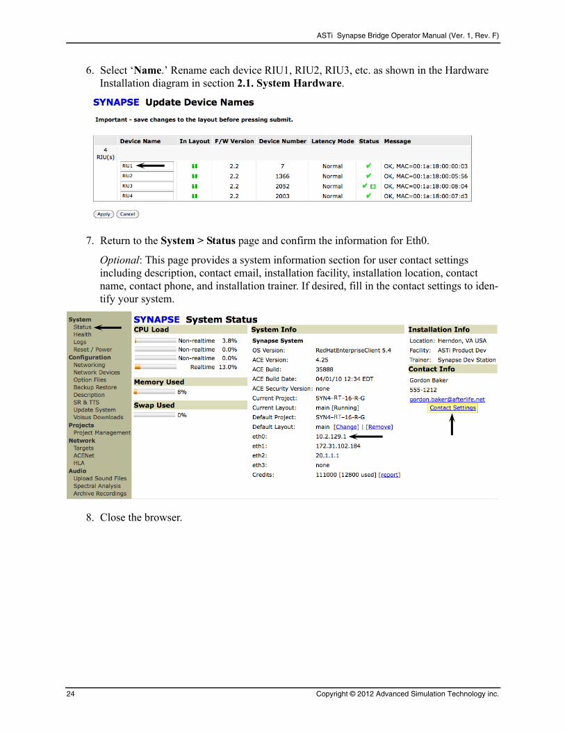
6. Select ‘Name.’ Rename each device RIU1, RIU2, RIU3, etc. as shown in the Hardware Installation diagram in section 2.1. System Hardware.
7. Return to the System > Status page and confirm the information for Eth0.
Optional: This page provides a system information section for user contact settings including description, contact email, installation facility, installation location, contact name, contact phone, and installation trainer. If desired, fill in the contact settings to iden-tify your system.
8. Close the browser.
24 Copyright © 2012 Advanced Simulation Technology inc.
ASTi Synapse Bridge Operator Manual (Ver. 1, Rev. F)
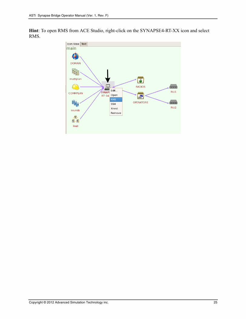
Hint: To open RMS from ACE Studio, right-click on the SYNAPSE4-RT-XX icon and select RMS.
Copyright © 2012 Advanced Simulation Technology inc. 25
ASTi Synapse Bridge Operator Manual (Ver. 1, Rev. F)
4.0. SYSTEM SOFTWARE CONFIGURATIONThe first step toward successful setup and integration of a Synapse system is coordination between all Synapse sites to ensure that critical communications parameters are defined. Follow the steps in this section to ensure proper configuration.
All software is pre-installed during factory system integration. Should you need to re-install the system software, please refer Appendix B Cold Start.
26 Copyright © 2012 Advanced Simulation Technology inc.
ASTi Synapse Bridge Operator Manual (Ver. 1, Rev. F)
4.1. Creating a Layout in ACE Studio
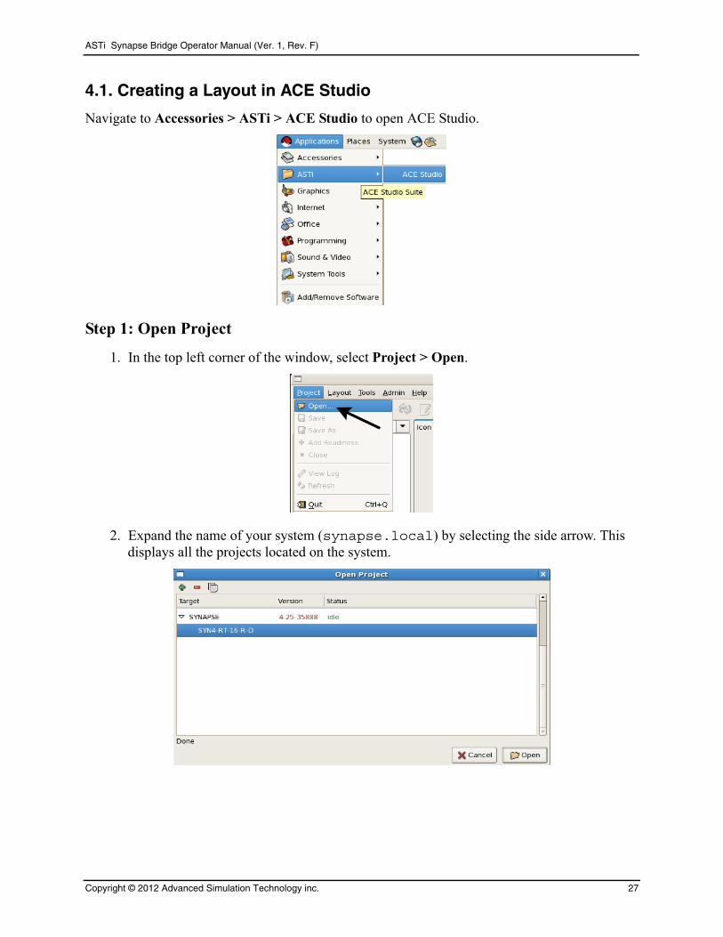
Navigate to Accessories > ASTi > ACE Studio to open ACE Studio.
Step 1: Open Project
1. In the top left corner of the window, select Project > Open.
2. Expand the name of your system (synapse.local) by selecting the side arrow. This displays all the projects located on the system.
Copyright © 2012 Advanced Simulation Technology inc. 27
ASTi Synapse Bridge Operator Manual (Ver. 1, Rev. F)
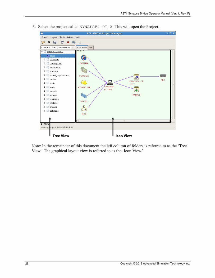
3. Select the project called SYNAPSE4-RT-X. This will open the Project.
Note: In the remainder of this document the left column of folders is referred to as the ‘Tree View.’ The graphical layout view is referred to as the ‘Icon View.’
28 Copyright © 2012 Advanced Simulation Technology inc.
ASTi Synapse Bridge Operator Manual (Ver. 1, Rev. F)
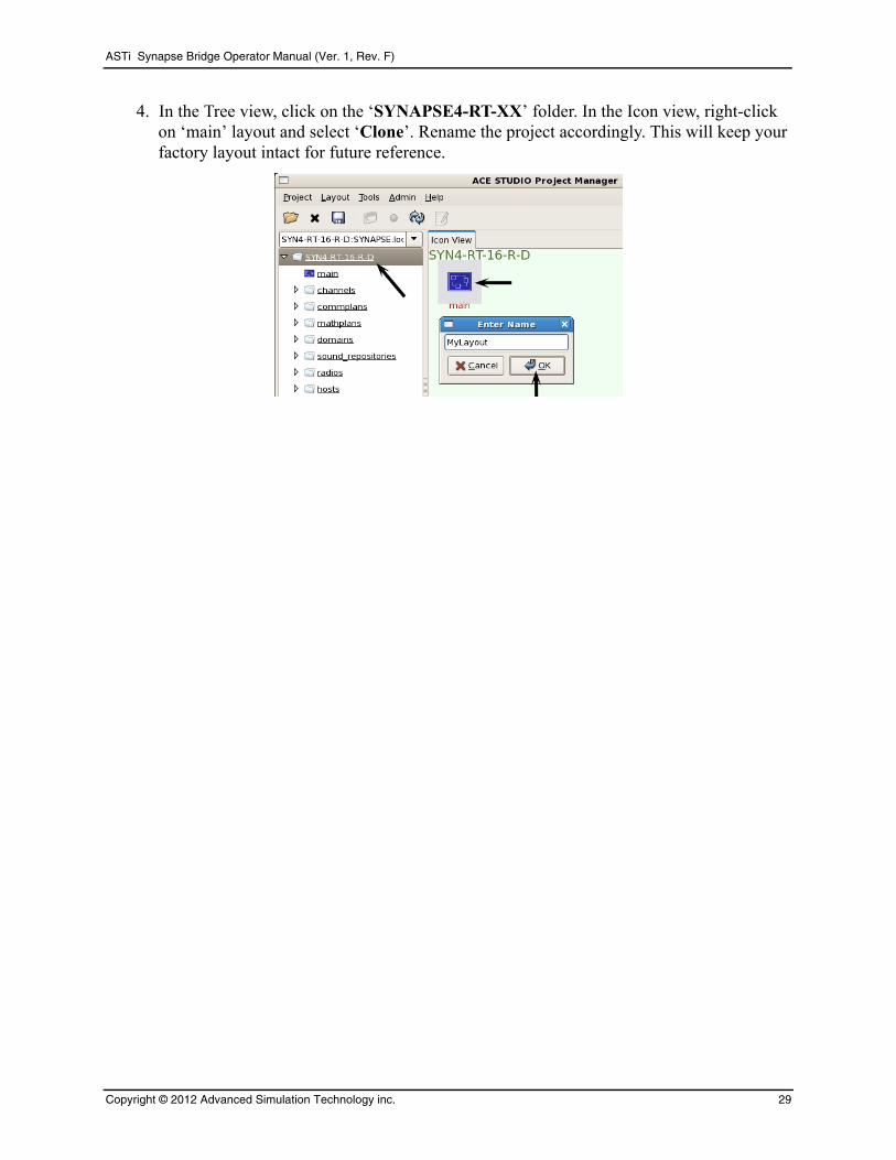
4. In the Tree view, click on the ‘SYNAPSE4-RT-XX’ folder. In the Icon view, right-click on ‘main’ layout and select ‘Clone’. Rename the project accordingly. This will keep your factory layout intact for future reference.
Copyright © 2012 Advanced Simulation Technology inc. 29
ASTi Synapse Bridge Operator Manual (Ver. 1, Rev. F)
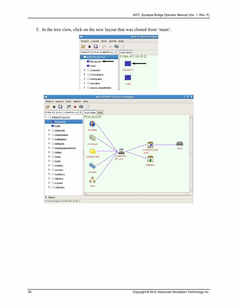
5. In the tree view, click on the new layout that was cloned from ‘main’.
30 Copyright © 2012 Advanced Simulation Technology inc.

ASTi Synapse Bridge Operator Manual (Ver. 1, Rev. F)
Step 2: Set DIS Gateway
1. In the Tree view, select the Servers folder.
2. In the Icon view, double-click the DIS Gateway. This opens the DIS Gateway window.
3. Fill in the DIS version number: 4, 5, or 6.
4. Select Eth0 for the interface and fill in a port number. The default port number is 53000.
Note: All of the Synapse Telestras on the DIS network must share a common DIS UDP Port number.
5. Next to ‘main’ enter the multicast or broadcast address. This sets the outgoing destination address for packets on the DIS port.
6. Then select ‘Ok’.
Copyright © 2012 Advanced Simulation Technology inc. 31

ASTi Synapse Bridge Operator Manual (Ver. 1, Rev. F)
Step 3: Set the Domain
Important: Although the original ‘main’ layout was cloned and replaced, the Helper/Builder icons (Domain, CommPlan, Operators, Radios, etc.) in the new layout are still connected to the ‘main’ layout. If you make changes to any of the Helper/Builder icons in the new layout, the ‘main’ icons will also have these changes. In order to maintain the original layout, it is important to clone and replace the new layout Helper/Builder icons.
1. In the Icon View, right-click the Domain icon and select ‘Clone and Replace’ and rename it.
2. Double-click the Domain icon.
3. Under ‘Add Domains’ select ‘DIS.’ Enter the DIS Exercise ID number.
Note that Synapse sites can only inter-communicate if they share the same DIS exercise ID.
4. Select to ‘Set IDs to Last Two IP Octets’ to automatically set the Site and App IDs.
Each Telestra on the network must have a unique set of DIS IDs.
32 Copyright © 2012 Advanced Simulation Technology inc.
ASTi Synapse Bridge Operator Manual (Ver. 1, Rev. F)
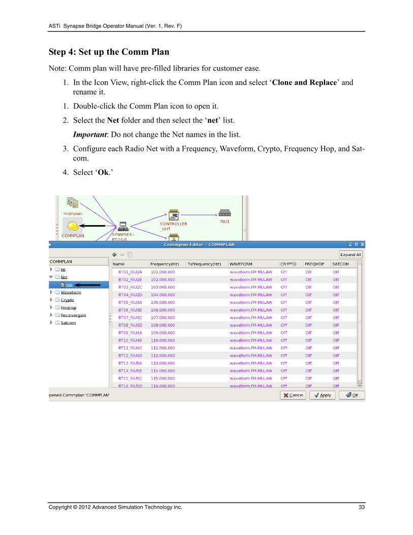
Step 4: Set up the Comm Plan
Note: Comm plan will have pre-filled libraries for customer ease.
1. In the Icon View, right-click the Comm Plan icon and select ‘Clone and Replace’ and rename it.
1. Double-click the Comm Plan icon to open it.
2. Select the Net folder and then select the ‘net’ list.
Important: Do not change the Net names in the list.
3. Configure each Radio Net with a Frequency, Waveform, Crypto, Frequency Hop, and Sat-com.
4. Select ‘Ok.’
Copyright © 2012 Advanced Simulation Technology inc. 33
ASTi Synapse Bridge Operator Manual (Ver. 1, Rev. F)
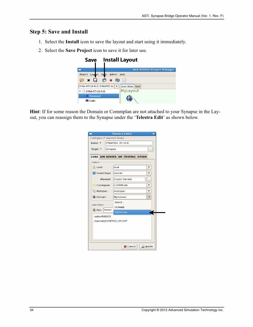
Step 5: Save and Install
1. Select the Install icon to save the layout and start using it immediately.
2. Select the Save Project icon to save it for later use.
Hint: If for some reason the Domain or Commplan are not attached to your Synapse in the Lay-out, you can reassign them to the Synapse under the ‘Telestra Edit’ as shown below.
34 Copyright © 2012 Advanced Simulation Technology inc.
ASTi Synapse Bridge Operator Manual (Ver. 1, Rev. F)
5.0. CONTROLLER STATION OPERATING CONCEPTSIn this section, the term intercom is used to mean intercom (for standard Synapse) or Simulated Radio (for Synapse option).
5.1. Controller Station Overview
1 2 3
4 5 6
7 8
0
9
PTT
ENTER
FreqNet
Status
Sql
Sidetone
Radio
OnOff Vol
RxTx
+
–
Shift DEL
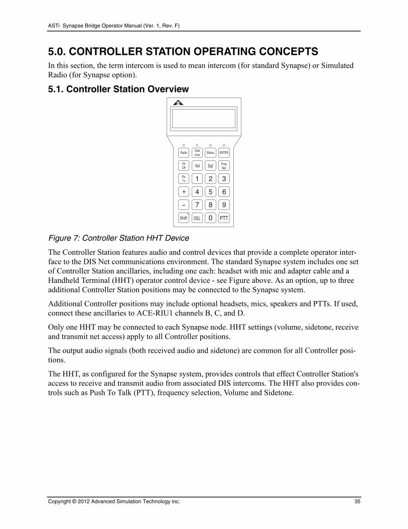
Figure 7: Controller Station HHT Device
The Controller Station features audio and control devices that provide a complete operator inter-face to the DIS Net communications environment. The standard Synapse system includes one set of Controller Station ancillaries, including one each: headset with mic and adapter cable and a Handheld Terminal (HHT) operator control device - see Figure above. As an option, up to three additional Controller Station positions may be connected to the Synapse system.
Additional Controller positions may include optional headsets, mics, speakers and PTTs. If used, connect these ancillaries to ACE-RIU1 channels B, C, and D.
Only one HHT may be connected to each Synapse node. HHT settings (volume, sidetone, receive and transmit net access) apply to all Controller positions.
The output audio signals (both received audio and sidetone) are common for all Controller posi-tions.
The HHT, as configured for the Synapse system, provides controls that effect Controller Station's access to receive and transmit audio from associated DIS intercoms. The HHT also provides con-trols such as Push To Talk (PTT), frequency selection, Volume and Sidetone.
Copyright © 2012 Advanced Simulation Technology inc. 35
ASTi Synapse Bridge Operator Manual (Ver. 1, Rev. F)
The Comm Plan tool provides pre-set values for the HHT. At system startup, these values are automatically read into the ACE software running on the Synapse and to the HHT display. Set-tings include:
• Master Volume: overall reception volume
• Sidetone Volume: “own-voice” volume for transmissions
• Intercom Volumes: individual reception volume settings for each intercom
• DIS intercom frequencies
Once the system is started, the HHT display shows the Controller Station communications status, as loaded from the Comm Plan tool. This main display is called the Status Page. This page shows information relating to the DIS Net environment, from the Controller position vantage point.
The top line of the Status Page contains the identifier “SYN-RT-XX”.
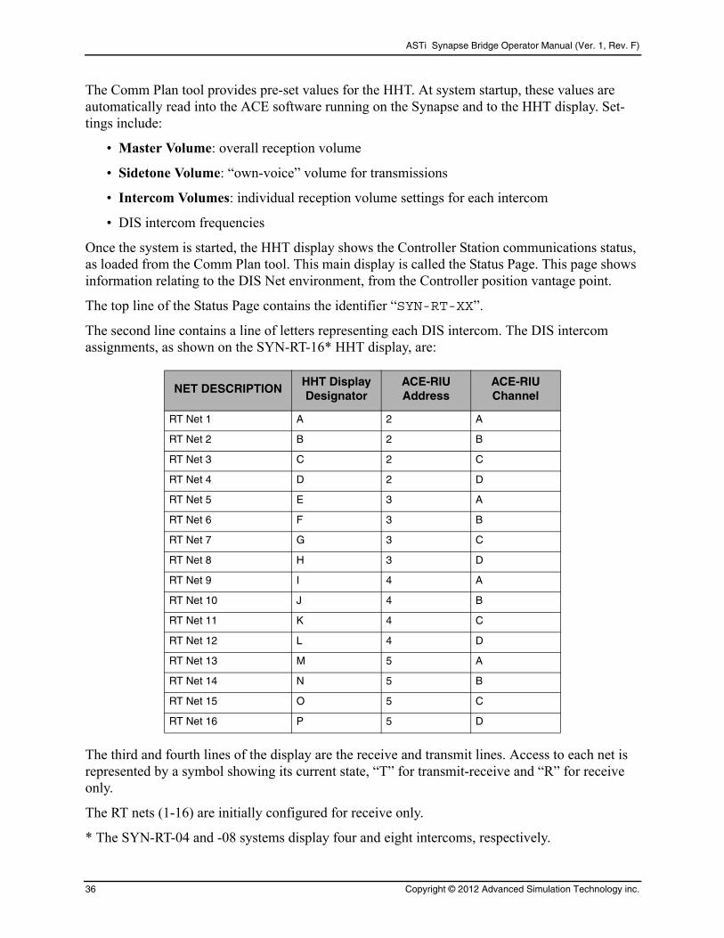
The second line contains a line of letters representing each DIS intercom. The DIS intercom assignments, as shown on the SYN-RT-16* HHT display, are:
NET DESCRIPTIONHHT Display Designator
ACE-RIU Address
ACE-RIUChannel
RT Net 1 A 2 A
RT Net 2 B 2 B
RT Net 3 C 2 C
RT Net 4 D 2 D
RT Net 5 E 3 A
RT Net 6 F 3 B
RT Net 7 G 3 C
RT Net 8 H 3 D
RT Net 9 I 4 A
RT Net 10 J 4 B
RT Net 11 K 4 C
RT Net 12 L 4 D
RT Net 13 M 5 A
RT Net 14 N 5 B
RT Net 15 O 5 C
RT Net 16 P 5 D
The third and fourth lines of the display are the receive and transmit lines. Access to each net is represented by a symbol showing its current state, “T” for transmit-receive and “R” for receive only.
The RT nets (1-16) are initially configured for receive only.
* The SYN-RT-04 and -08 systems display four and eight intercoms, respectively.
36 Copyright © 2012 Advanced Simulation Technology inc.

ASTi Synapse Bridge Operator Manual (Ver. 1, Rev. F)
5.2. Controller Station Operation
Controller Station communications parameters can be set using the HHT keys after the system is running. The user can modify the following parameters: Master Volume, Net Volume (for each net), Sidetone, and frequency for each net.
Controller HHT Keypad Operation
Master Volume
From the main Status screen, press Vol then either press the numeric key 0-9 for the desired
volume, or ramp up or down using + and – followed by ENTER .
Controller Volume Page
Volume: 5
SYN-RT-16-R
Volume: 5
SYN-RT-16-R
Sidetone
From the main Status screen, press Sidetone then either press the numeric key 0-9 for the desired
sidetone, or ramp up or down using + and – followed by ENTER .
Controller Sidetone Page
Sidetone: 5
SYN-RT-16-R
Sidetone: 5
SYN-RT-16-R
Copyright © 2012 Advanced Simulation Technology inc. 37

ASTi Synapse Bridge Operator Manual (Ver. 1, Rev. F)
Transmit Select
To select a particular intercom to Transmit and Receive, press the two-digit number (e.g., 01, 02, 15, etc.) of the intercom from the Status Page.
38 Copyright © 2012 Advanced Simulation Technology inc.

ASTi Synapse Bridge Operator Manual (Ver. 1, Rev. F)
APPENDIX A: SYNAPSE ACE-RIU TECHNICAL SPECSGeneral Information
There are two ACE-RIU special configurations for use with the Synapse Bridge:
Operator ACE-RIU: Interface module for Controller Station. The device is marked as “ACE-RIU”.
Radio ACE-RIU: Interface module for radio transceivers. The device is marked as “Radio ACE-RIU”.
A packaged ACE-RIU weighs 1.5 lbs. The power supply included with the ACE-RIU weighs 0.5 lbs. 19”, 1U high rackmount kits are available. Each kit will hold 3 ACE-RIUs.
Each ACE-RIU is pre-configured at the factory, prior to shipping. If you have any concerns that the internal settings of the ACE-RIUs have been changed from the factory settings, open the ACE-RIU case and check the settings before starting the system.
Configure the hardware settings for each ACE-RIU using the following guidelines.
The internal jumpers are accessed by removing the two faceplate screws on the ACE-RIU front face, removing the faceplate and bezel and sliding the top cover off. IMPORTANT: This opera-tion must be performed at an approved ESD station to avoid damaging the equipment and voiding the manufacturer warranty.
ACE-RIU internal jumper settings:
DESCRIPTIONJUMPER SETTING
Operator ACE-RIU Radio ACE-RIU
Input Gain, Channel A J1 40 dB 0 dB
Input Gain, Channel B J2 40 dB 0 dB
Input Gain, Channel C J3 40 dB 0 dB
Input Gain, Channel D J4 40 dB 0 dB
Output Coupling, Channel A J5 OPEN OPEN
Output Coupling, Channel B J6 OPEN OPEN
Output Coupling, Channel C J7 OPEN OPEN
Output Coupling, Channel D J8 OPEN OPEN
Copyright © 2012 Advanced Simulation Technology inc. 39
ASTi Synapse Bridge Operator Manual (Ver. 1, Rev. F)
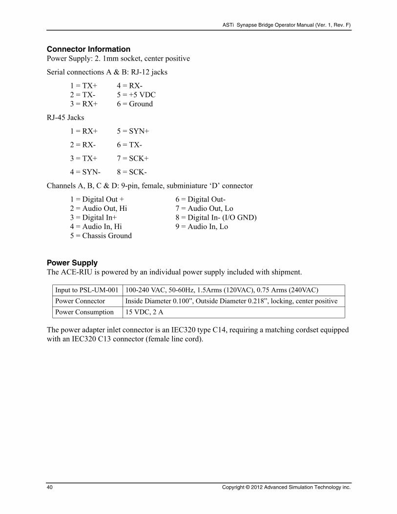
Connector InformationPower Supply: 2. 1mm socket, center positive
Serial connections A & B: RJ-12 jacks
1 = TX+ 4 = RX-2 = TX- 5 = +5 VDC3 = RX+ 6 = Ground
RJ-45 Jacks
1 = RX+ 5 = SYN+
2 = RX- 6 = TX-
3 = TX+ 7 = SCK+
4 = SYN- 8 = SCK-
Channels A, B, C & D: 9-pin, female, subminiature ‘D’ connector
1 = Digital Out + 6 = Digital Out-2 = Audio Out, Hi 7 = Audio Out, Lo3 = Digital In+ 8 = Digital In- (I/O GND)4 = Audio In, Hi 9 = Audio In, Lo5 = Chassis Ground
Power SupplyThe ACE-RIU is powered by an individual power supply included with shipment.
Input to PSL-UM-001 100-240 VAC, 50-60Hz, 1.5Arms (120VAC), 0.75 Arms (240VAC)
Power Connector Inside Diameter 0.100”, Outside Diameter 0.218”, locking, center positive
Power Consumption 15 VDC, 2 A
The power adapter inlet connector is an IEC320 type C14, requiring a matching cordset equipped with an IEC320 C13 connector (female line cord).
40 Copyright © 2012 Advanced Simulation Technology inc.
ASTi Synapse Bridge Operator Manual (Ver. 1, Rev. F)
APPENDIX B: COLD STARTShould you need to re-install the system software, please refer to the ASTi Synapse Cold Start and Installation Manual (DOC-01-SYN4-CSI-1).
Refer to the ASTi web site to download the ASTi Synapse Cold Start and Installation Manual and other Synapse documentation.
http://www.asti-usa.com/support/document/synapse.html
Copyright © 2012 Advanced Simulation Technology inc. 41
ASTi Synapse Bridge Operator Manual (Ver. 1, Rev. F)
APPENDIX C: SAFETY AND HANDLINGThis section must be read completely and understood before using the Synapse Bridge. If you are unsure of any information presented please contact ASTi.
The following safety precautions must be observed when performing any operation and mainte-nance tasks associated with the ASTi Synapse Bridge. These safety precautions are necessary to prevent injury to personnel and damage to equipment.
Warning: Potentially fatal voltages are present in the Synapse Bridge. Before removing, or replacing any component, ensure that ALL electrical supplies have been turned off and electrical power cords disconnected from the platform.
The following disclaimer is provided regarding use of the Synapse Bridge. The disclaimer applies to all parties using the system in any situation or configuration. This disclaimer should be read and understood completely before using the system.
Disclaimer: The Synapse Bridge is a sound production device. The user, by the act of installing and using the Synapse Bridge and any associated equipment such as external amplifiers, headsets, speakers, etc., warrants and represents that he/she is aware that excessive audio levels can cause permanent hearing impairment and that he/she assumes full responsibility for configuring all equipment including hardware and software to achieve safe operating sound pressure levels under all conditions.
Equipment Handling: All platform circuit boards and modules are sensitive to electrostatic dis-charge (ESD). To avoid damage to system equipment, proper ESD procedures should be followed when handling all equipment. Ensure that all work is performed at a properly grounded ESD work station. In addition, all personnel handling equipment should be properly grounded.
When transporting or shipping individual modules, equipment should be fully enclosed in an anti-static bag. ASTi is not responsible for equipment damage due to improper handling.
42 Copyright © 2012 Advanced Simulation Technology inc.
ASTi Synapse Bridge Operator Manual (Ver. 1, Rev. F)
APPENDIX D: WARRANTY AND CUSTOMER SUPPORTWarranty
ASTi provides a one year limited warranty on all ASTi equipment covering all parts and labor.
In the case of equipment upgrades, warranty applies to original date of shipment of individual components.
Other commercial equipment purchased or provided such as monitors, amplifiers, speakers, fiber optic links, etc. are also covered under the one year warranty unless otherwise stated.
The warranty does not cover improper equipment handling or improperly packaged returns.
Extended warranties are available. Contact ASTi for details (703) 471-2104.
Repairs and Returns
If it becomes necessary to return equipment to ASTi, please observe the following instructions:
Obtain an RMA number through ASTi’s website: http://www.asti-usa.com/support/
When packaging the equipment in question, make sure it is well protected. The device should be properly enclosed in an antistatic bag to prevent possible ESD damage. Failure to properly pack-age the equipment during shipping could void the warranty.
Do not include accessory pieces such as rackmount kids, power supplies or software. Only send items that do not work.
The shipping label must include the RMA number.
Include a description of the problem, point of contact, phone number, return address and unit serial number(s). Failure to include this information could extensively delay the return of the equipment.
Evaluation of equipment is performed free of charge. No work will be done without prior cus-tomer approval. Customer is responsible for shipping charges to ASTi for warranty and non-war-ranty repairs.
If an RMA number is not used within thirty (30) days of issuing date, the request data and number issued will be closed and designated as unused.
Any items received from customers without RMA numbers or appropriate contact information included with shipment will not be tested. After sixty (60) days, ASTi reserves the right to scrap all hardware received in this condition.
If the equipment is not under warranty a Purchase Order will be required to cover the cost of any repairs. ASTi will provide a quote for all non-warranty repair items.
Equipment will be shipped back using Federal Express, unless otherwise directed. If the repair is non-warranty then shipping charges will be billed.
International customers must include the correct product value on all shipping documents. Con-tact ASTi for proper harmonized tariff codes. The customer is responsible for all duties, taxes and fees incurred in shipment of the equipment.
Copyright © 2012 Advanced Simulation Technology inc. 43
ASTi Synapse Bridge Operator Manual (Ver. 1, Rev. F)
APPENDIX E: FURTHER READINGFor detailed operational information about the RTs see:
1. US ARMY, Operator's Manual, SINCGARS Ground Combat Net Radio. RT-1523C/D (SIP) and RT-1523E (ASIP) Versions.
2. AN/PRC-117F(v)(c) Operations Manual, Number 10515-0109-4100, March 2000, Rev. C.
3. AN/PRC-148(V)3(C), (V)4(C), (V)5(C) and (V)6(C), Operation and Maintenance Instructions, Thales PN 84357, Rev D.
44 Copyright © 2012 Advanced Simulation Technology inc.
Related Documents