Assessment of GPS/MEMS-IMU Integration Performance in Ski Racing Adrian Waegli, Jan Skaloud Ecole polytechnique fédérale de Lausanne (EPFL), Switzerland BIOGRAPHY Adrian Waegli obtained a M.Sc. in Geomatics Engineering from EPF Lausanne, Switzerland for his work on the ionospheric corrections of EGNOS. After working as a surveyor at the Swiss Federal Office of Topography, he joined the Geodetic Engineering Laboratory of EPFL in 2004 as Ph.D. student. His research focuses on the integration of satellite and inertial navigation systems for performance analysis in sports. Jan Skaloud is a scientist and lecturer at the Institute of Geomatics at EPF Lausanne, Switzerland. He holds a Ph.D. and M.Sc. in Geomatics Engineering from the University of Calgary and Dipl. Ing. in Surveying Engineering from the Czech Institute of Technology, Prague. He has been involved with the GPS research and development since 1993 and has worked extensively on the integration of GPS and inertial navigation systems for precise airborne and terrestrial mapping. KEYWORDS GPS/INS integration, MEMS, magnetic disturbance, navigation performance, trajectory analysis ABSTRACT This paper describes an experiment involving a professional downhill skier equipped with GPS and MEMS-IMU, as well as a triad of magnetometers and a tactical-grade inertial unit. The experiment illustrates the navigation performance of GPS/MEMS integration compared to high-quality GPS/INS integration challenged by the environmental conditions and dynamics of ski-racing. The MEMS sensors’ output is directly compared to the reference signals. This information is used to validate the error models of the inertial and magnetic measurements and to select the appropriate integration algorithms. INTRODUCTION Today, material development and testing in Alpine skiing is based on repeated measurements with timing cells or in wind tunnels; the performance analysis of athletes on simple chronometry and video recordings. These methods appear to be vulnerable to meteorological conditions and the fatigue of the test persons. Furthermore, current methods based on videogrammetry [1] and approaches based on timing cells don’t offer a flexible choice of the intermediate times and the analysis of accelerations and velocities along the whole track. Therefore, new methods offering precise determination of the skiers’ position, velocity and attitude are wanted. Satellite-based positioning has already proven its effectiveness in car racing [2], rowing [3] and Alpine Skiing [4]. The latter used dual-frequency GPS receivers to reconstruct the skiers’ trajectories. Because of ergonomic and economic restrictions, theses receivers will be reserved to few Sports applications with higher accuracy needs. [5] has shown that L1 only receivers were capable to determine the peak velocity of the speed skier with similar accuracies than dual- frequency receivers. [6] has demonstrated that the timing accuracies provided by L1 GPS chronometry achieved the same level of accuracy as L1/L2 GPS chronometry and traditional chronometry based on timing cells provided that the carrier-phase ambiguities were solved. However, considering the high dynamics of a skier and the ergonomic requirements placed on the equipment, today’s technological limits in GPS positioning are quickly reached or even exceeded [7]. Furthermore, the athlete’s environment is quickly alternating between open spaces and areas that are adverse to the reception of satellite signals (sudden satellite masking) which makes the carrier-phase ambiguity resolution difficult or even impossible. Furthermore, athletes and coaches are not only interested in the trajectories and velocities, but also in the motion analysis of segments of the human or the attitude of his equipment [8]. Therefore, this paper introduces a system of low cost Micro-Electro-Mechanical System (MEMS) Inertial

Welcome message from author
This document is posted to help you gain knowledge. Please leave a comment to let me know what you think about it! Share it to your friends and learn new things together.
Transcript

Assessment of GPS/MEMS-IMU Integration Performance in Ski Racing
Adrian Waegli, Jan Skaloud Ecole polytechnique fédérale de Lausanne (EPFL), Switzerland
BIOGRAPHY Adrian Waegli obtained a M.Sc. in Geomatics Engineering from EPF Lausanne, Switzerland for his work on the ionospheric corrections of EGNOS. After working as a surveyor at the Swiss Federal Office of Topography, he joined the Geodetic Engineering Laboratory of EPFL in 2004 as Ph.D. student. His research focuses on the integration of satellite and inertial navigation systems for performance analysis in sports. Jan Skaloud is a scientist and lecturer at the Institute of Geomatics at EPF Lausanne, Switzerland. He holds a Ph.D. and M.Sc. in Geomatics Engineering from the University of Calgary and Dipl. Ing. in Surveying Engineering from the Czech Institute of Technology, Prague. He has been involved with the GPS research and development since 1993 and has worked extensively on the integration of GPS and inertial navigation systems for precise airborne and terrestrial mapping.
KEYWORDS GPS/INS integration, MEMS, magnetic disturbance, navigation performance, trajectory analysis
ABSTRACT This paper describes an experiment involving a professional downhill skier equipped with GPS and MEMS-IMU, as well as a triad of magnetometers and a tactical-grade inertial unit. The experiment illustrates the navigation performance of GPS/MEMS integration compared to high-quality GPS/INS integration challenged by the environmental conditions and dynamics of ski-racing. The MEMS sensors’ output is directly compared to the reference signals. This information is used to validate the error models of the inertial and magnetic measurements and to select the appropriate integration algorithms.
INTRODUCTION Today, material development and testing in Alpine skiing is based on repeated measurements with timing cells or in wind tunnels; the performance analysis of athletes on simple chronometry and video recordings. These methods appear to be vulnerable to meteorological conditions and the fatigue of the test persons. Furthermore, current methods based on videogrammetry [1] and approaches based on timing cells don’t offer a flexible choice of the intermediate times and the analysis of accelerations and velocities along the whole track. Therefore, new methods offering precise determination of the skiers’ position, velocity and attitude are wanted. Satellite-based positioning has already proven its effectiveness in car racing [2], rowing [3] and Alpine Skiing [4]. The latter used dual-frequency GPS receivers to reconstruct the skiers’ trajectories. Because of ergonomic and economic restrictions, theses receivers will be reserved to few Sports applications with higher accuracy needs. [5] has shown that L1 only receivers were capable to determine the peak velocity of the speed skier with similar accuracies than dual-frequency receivers. [6] has demonstrated that the timing accuracies provided by L1 GPS chronometry achieved the same level of accuracy as L1/L2 GPS chronometry and traditional chronometry based on timing cells provided that the carrier-phase ambiguities were solved. However, considering the high dynamics of a skier and the ergonomic requirements placed on the equipment, today’s technological limits in GPS positioning are quickly reached or even exceeded [7]. Furthermore, the athlete’s environment is quickly alternating between open spaces and areas that are adverse to the reception of satellite signals (sudden satellite masking) which makes the carrier-phase ambiguity resolution difficult or even impossible. Furthermore, athletes and coaches are not only interested in the trajectories and velocities, but also in the motion analysis of segments of the human or the attitude of his equipment [8]. Therefore, this paper introduces a system of low cost Micro-Electro-Mechanical System (MEMS) Inertial

2
Navigation Systems (INS) integrated with L1 GPS observations. The MEMS sensor consists of inertial sensors (triple axis accelerometer and gyroscopes), as well as a triad of magnetometers. As it will be shown, the combination of these sensors helps to overcome the lack of continuity of the GPS signals in difficult environment and to determine accurately the orientation of the MEMS sensor and brings answers to the above questions. The MEMS sensors are suitable for this application also due to their small size and low cost. Unfortunately, the MEMS measurements are prone to large systematic errors. Although, their suitability for navigation has been demonstrated [9]. Their potential has to be investigated for sports applications, and particularly for those of high dynamics such as Alpine skiing. This article investigates the performance of the L1 GPS/MEMS system based on an experiment where a professional downhill skier was equipped with GPS, MEMS inertial and magnetic sensors and a tactical-grade inertial unit. The first two sections present the integration strategy and experimental setup. Then, the integration quality provided by the MEMS sensors and by the overall system is investigated. Firstly, the MEMS measurements are combined to the reference dual-frequency GPS solution in order to isolate the MEMS errors from those introduced by the L1-only GPS solution. Then, comparing the raw inertial signals to the tactical-grade IMU, the MEMS error model is validated. Finally, the overall system performance is examined.
THEORETICAL BACKGROUND The L1 GPS/MEMS integration presented in this article is based on an extended Kalman filter (EKF) and a loosely coupled integration strategy. The MEMS-IMU measurements are adjusted for gravity and Earth rotation in the strapdown algorithm (Figure 1). The MEMS magnetic measurements are corrected for magnetic perturbations or disturbances before being introduced into the filter. GPS coordinates and velocities are fed into the EKF after post-processing. The EKF was implemented in the local level frame to make the state interpretation straightforward. The following strapdown equations need to be solved [10]:
( )( )
= - × +
-
⎡ ⎤⎡ ⎤ ⎢ ⎥⎢ ⎥ ⎢ ⎥⎢ ⎥ ⎢ ⎥⎢ ⎥ ⎢ ⎥⎣ ⎦ ⎣ ⎦
D vrv R f ω +ω v gR R ω ω
-1 nn
n n b n n n nb in ie
n n b bb b ib in
Eq. 1
For the inertial measurements, a simplified error model was considered, judging that the misalignments, drifts and constant offsets could not be decorrelated efficiently given the characteristics of the MEMS sensors. Only a bias modeled as first order Gauss-
Markov process for each inertial measurement is estimated:
ˆ
2β σ β
= + +
= − ⋅ + ⋅
b w
b b w
b b
b b b b b
b b
Eq. 2
where ˆ b is the compensated MEMS measurement (specific force, rotation rate or magnetic field measurement), b the raw measurement, b b the bias
of the MEMS measurement, w b the measurement
noise and β the inverse of the correlation time. A choice had also to be made with respect to the magnetometers. These sensors are beneficial in the attitude estimation and help indirectly to bridge the gaps in GPS positioning and are useful for initialisation. Unfortunately, they are prone to magnetic disturbances and sensitive to high frequency accelerations [11]. Their measurements are introduced as external measurements:
( )ˆ = - +mh ⋅x R h d w- b nk n m m Eq. 3
where hn is the Earth’s magnetic field vector for a specific location and time and dm the magnetic perturbation vector expressed in the body frame.
Figure 1: Structure of the loosely coupled filter After forward filtering, a backward smoother based on the Rauch-Tung-Striebel (RTS) algorithm is applied [12]:
( )( )( )
1
1
, 1, 1
, 1, 1
Tk k k k
k RTS k k k RTS k
Tk RTS k k k RTS k k
−+ −+
+ + + −+ +
+ + + −+ +
= ⋅ ⋅
= + ⋅ −
= + ⋅ − ⋅
J P P
x x J x x
P P J P P J
φ
Eq. 4

3
where x represents the state vector, φ the transition matrix and P the covariance matrix. Subscript k makes reference to time kt , while RTS indicates the RTS-smoothed solution. Superscript + and − denote compensated and predicted states.
EXPERIMENTAL SETUP In order to investigate the navigation performance of the L1 GPS/MEMS system, the latter was mounted in a backpack together with a reference dual-frequency GPS receiver (Javad) and a tactical-grade IMU (LN200). The MEMS sensors (xsens MTi) were fixed tightly to the reference IMU with a fixed lever arm. A dozen of downhills of approximately 1 minute duration were performed by a professional skier. Each run was preceded by a static initialization phase of 2-3 minutes.
Figure 2 : Experimental setup mounted on a professional skier
MEMS INTERPOLATION PERFORMANCE In order to assess the MEMS performance independently from the L1 GPS precision, MEMS inertial and MEMS magnetic measurements are first integrated with the GPS L1/L2 reference solution. The IMU integration is performed at 100Hz with position and velocity updates at 1Hz and magnetic updates at 20Hz. The backward smoothing algorithm (Rauch-Tung-Striebel) is applied in the sequel. The MEMS integration is evaluated by comparing it to the reference solution (LN200 and GPS L1/L2). The MEMS navigation performance (position, velocity and attitude, PVA) was evaluated for 4 ski trajectories. GPS outages of 5s, 10s and 15s were simulated after 10-15 s from the start. Even though GPS outages longer than 5s are unusual in Alpine skiing, longer outages were simulated in order to evaluate the gap filling performance of MEMS sensors in more detail. The MEMS magnetic measurements were alternately omitted.
Position and Velocity Accuracy Figure 3 illustrates a simulated 10s GPS outage during a giant slalom. The forward filtered solution starts to diverge after 5 seconds above a permissible level. However, the backward smoothing algorithm corrects this divergence efficiently. The gates, added as external reference, were measured with GPS dual-frequency receivers and computed in post-processing.
Figure 3 : 10s GPS outage during downhill skiing Figure 4 and figure 5 show the coordinate and velocity innovations of a run processed in forward direction. The coordinate update innovations are smaller than 0.5m and the velocity update innovations are around 0.5m/s (horizontal) and 1.4m/s (vertical). They are efficiently reduced by the RTS algorithm (Figure 3). No systematic improvement is realized by the application of magnetic updates.
Figure 4: Coordinate update innovations (downhill without GPS outages, forward filtering, with and without magnetic updates) Table 1 to table 3 summarize the maximum errors of the 4 runs during the simulated outages. The coordinate error does not exceed 50cm, even in the case of the simulated 5s GPS outages. With the GPS outage duration increasing, the error grows to 1m (10s GPS outage) and 1.5-2m (15s GPS outage). The velocity and attitude estimates are only weakly influenced by the GPS gaps. Maximum velocity errors of 0.4m/s are
xsens MTi
LN200
Javad Legacy
4
encountered which are almost unaffected by the different duration of GPS outages.
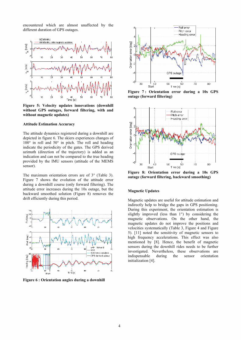
Figure 5: Velocity updates innovations (downhill without GPS outages, forward filtering, with and without magnetic updates) Attitude Estimation Accuracy The attitude dynamics registered during a downhill are depicted in figure 6. The skiers experiences changes of 100° in roll and 50° in pitch. The roll and heading indicate the periodicity of the gates. The GPS derived azimuth (direction of the trajectory) is added as an indication and can not be compared to the true heading provided by the IMU sensors (attitude of the MEMS sensor). The maximum orientation errors are of 3° (Table 3). Figure 7 shows the evolution of the attitude error during a downhill course (only forward filtering). The attitude error increases during the 10s outage, but the backward smoothed solution (Figure 8) removes the drift efficiently during this period.
Figure 6 : Orientation angles during a downhill
Figure 7 : Orientation error during a 10s GPS outage (forward filtering)
Figure 8: Orientation error during a 10s GPS outage (forward filtering, backward smoothing) Magnetic Updates Magnetic updates are useful for attitude estimation and indirectly help to bridge the gaps in GPS positioning. During this experiment, the orientation estimation is slightly improved (less than 1°) by considering the magnetic observations. On the other hand, the magnetic updates do not improve the positions and velocities systematically (Table 3, Figure 4 and Figure 5). [11] noted the sensitivity of magnetic sensors to high frequency accelerations. This effect was also mentioned by [8]. Hence, the benefit of magnetic sensors during the downhill rides needs to be further investigated. Nevertheless, these observations are indispensable during the sensor orientation initialization [4].

5
Table 1 : Summary of the maximum PVA errors during the simulated outages on 4 trajectories (forward filtering, backward smoothing, without magnetic updates)
Table 2 : Summary of the maximum PVA errors during the simulated outages on 4 trajectories (forward filtering, backward smoothing, with magnetic updates)
Table 3 : Differences of the maximum PVA errors (with and without magnetic updates) Summary GPS outages up to 5s are frequent in skiing, whereas 10s updates are very rare. The outages were simulated at the beginning of the downhills, after 10-15s of skiing. The results show the fast convergence of the filter parameters that is crucial in the sports application where the dynamics can vary strongly within short periods of time. Thus, MEMS measurements can be integrated with GPS to obtain sufficiently accurate results during GPS outages up a few seconds in spite of the high dynamics in skiing racing.
MEMS ERROR MODEL VALIDATION The raw MEMS signals can be directly compared to the LN200 signals which are considered as reference. Hence, the MEMS constant systematic errors can be for instance evaluated during static initialization phase and then compared to the biases modeled by the EKF. The determination of the boresight alignment of the two sensors is prerequisite for an accurate comparison. The boresight angles were determined by feeding the EKF with the reference attitude angles provided by the LN200:
3 200ˆ( ) ( )
2LN
B B
h ϕ
ϕβ σ β
− = + +
= − ⋅ + ⋅
x I B φ w
B B w Eq. 5
where B is the skew-symmetric form of the boresight angles, 200LNφ are the attitude angles from the
reference solution, ϕw the measurement noise and
Bβ the inverse of the correlation time “fixed” to infinity.
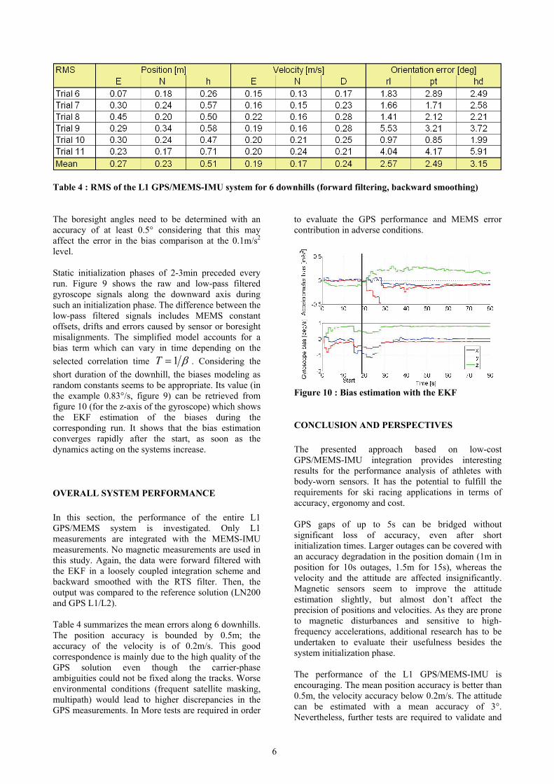
Figure 9: Rotation rate of gyroscope Z during the static initialization phase before the run (2.5min duration)
6
Table 4 : RMS of the L1 GPS/MEMS-IMU system for 6 downhills (forward filtering, backward smoothing) The boresight angles need to be determined with an accuracy of at least 0.5° considering that this may affect the error in the bias comparison at the 0.1m/s2 level. Static initialization phases of 2-3min preceded every run. Figure 9 shows the raw and low-pass filtered gyroscope signals along the downward axis during such an initialization phase. The difference between the low-pass filtered signals includes MEMS constant offsets, drifts and errors caused by sensor or boresight misalignments. The simplified model accounts for a bias term which can vary in time depending on the selected correlation time 1T β= . Considering the short duration of the downhill, the biases modeling as random constants seems to be appropriate. Its value (in the example 0.83°/s, figure 9) can be retrieved from figure 10 (for the z-axis of the gyroscope) which shows the EKF estimation of the biases during the corresponding run. It shows that the bias estimation converges rapidly after the start, as soon as the dynamics acting on the systems increase.
OVERALL SYSTEM PERFORMANCE In this section, the performance of the entire L1 GPS/MEMS system is investigated. Only L1 measurements are integrated with the MEMS-IMU measurements. No magnetic measurements are used in this study. Again, the data were forward filtered with the EKF in a loosely coupled integration scheme and backward smoothed with the RTS filter. Then, the output was compared to the reference solution (LN200 and GPS L1/L2). Table 4 summarizes the mean errors along 6 downhills. The position accuracy is bounded by 0.5m; the accuracy of the velocity is of 0.2m/s. This good correspondence is mainly due to the high quality of the GPS solution even though the carrier-phase ambiguities could not be fixed along the tracks. Worse environmental conditions (frequent satellite masking, multipath) would lead to higher discrepancies in the GPS measurements. In More tests are required in order
to evaluate the GPS performance and MEMS error contribution in adverse conditions.
Figure 10 : Bias estimation with the EKF
CONCLUSION AND PERSPECTIVES The presented approach based on low-cost GPS/MEMS-IMU integration provides interesting results for the performance analysis of athletes with body-worn sensors. It has the potential to fulfill the requirements for ski racing applications in terms of accuracy, ergonomy and cost. GPS gaps of up to 5s can be bridged without significant loss of accuracy, even after short initialization times. Larger outages can be covered with an accuracy degradation in the position domain (1m in position for 10s outages, 1.5m for 15s), whereas the velocity and the attitude are affected insignificantly. Magnetic sensors seem to improve the attitude estimation slightly, but almost don’t affect the precision of positions and velocities. As they are prone to magnetic disturbances and sensitive to high-frequency accelerations, additional research has to be undertaken to evaluate their usefulness besides the system initialization phase. The performance of the L1 GPS/MEMS-IMU is encouraging. The mean position accuracy is better than 0.5m, the velocity accuracy below 0.2m/s. The attitude can be estimated with a mean accuracy of 3°. Nevertheless, further tests are required to validate and

7
improve the MEMS error model and to evaluate the need for other integration strategies. Furthermore, the system has to be tested in situations with adverse conditions to GPS reception. Closely coupled integration could provide improvements in conditions with difficult satellite reception. The convergence criterion is very important in sports, where the trajectories are of short duration and where the filter has to adapt rapidly to the changing dynamics. Although the presented filter demonstrated good convergence, other integration strategies will be tested in order to further improve this aspect.
ACKNOWLEDGEMENTS This research is financed by TracEdge, based at Chambéry, France. The authors greatly appreciate the support of Pierre Ribot for his courageous downhill performances.
REFERENCES [1] W. Nachbauer, P. Kaps, B. M. Nigg, F.
Brunner, A. Lutz, G. Obkircher, and M. Mössner, "A video technique for obtaining 3-D coordinates in Alpine skiing," Journal of Applied Biomechanics, pp. 104-115, 1996.
[2] J. How, N. Pohlman, and C.-W. Park, "GPS Estimation Algorithms for Precise Velocity, Slip and Race-track Position Measurements," in SAE Motorsports Engineering Conference & Exhibition, 2002.
[3] K. Zhang, R. Grenfell, R. Deakin, Y. Li, Jason Zhang, A. Hahn, C. Gore, and T. Rice, "Towards a Low-Cost, High Output Rate, Real-Time GPS Rowing Coaching and Training System," in 16th International Technical Meeting of the Satellite Division of The Institute of Navigation, Portland, 2003.
[4] J. Skaloud and P. Limpach, "Synergy of CP-DGPS, Accelerometry and Magnetic Sensors for Precise Trajectography in Ski Racing," in ION GPS/GNSS 2003, Portland, 2003.
[5] J. Skaloud, H. Gontran, and B. Merminod, "GSM-Distributed RTK for Precise Analysis of Speed Skiing," in 8th European Navigation Conference GNSS 2004, Rotterdam, 2004.
[6] A. Waegli and J. Skaloud, "Turning Point – Trajectory Analysis for Skiers," InsideGNSS, Spring 2007.
[7] J. Skaloud and B. Merminod, "DGPS-Calibrated Accelerometric System for Dynamic Sports Events," in ION GPS, Salt Lake City, 2000.
[8] A. Waegli and J. Skaloud, "Turning Point – Trajectory Analysis for Skiers," InsideGNSS, 2007.
[9] N. El-Sheimy and X. Niu, "The Promise of MEMS to the Navigation Community," InsideGNSS, 2007.
[10] D. H. Titterton and J. L. Weston, Strapdown inertial navigation technology: Peter Peregrinus Ltd, 1997.
[11] D. Törnqvist, "Statistical Fault Detection with Applications to IMU Disturbances," in Department of Electrical Engineering: Linköping, Sweeden, 2006.
[12] A. Gelb, Applied Optimal Estimation vol. 14: MIT Press, 1994.
Related Documents