ASSEMBLY INSTRUCTIONS FOR DYNAPRO LOW-PROFILE PRO SERIES REAR PARKING BRAKE KIT WITH 11.00” DIAMETER VENTED ROTOR (2.36 OFFSET) MOPAR 8-3/4 • DANA 60 FOR USE W/GREEN (1) NON-ADJUSTABLE BEARINGS W/SNAP RING PART NUMBER GROUP 140-11395 NOTE: Some cleaners may stain or remove the finish on brake system components. Test the cleaner on a hidden portion of the component before general use. WARNING IT IS THE RESPONSIBILITY OF THE PERSON INSTALLING ANY BRAKE COMPONENT OR KIT TO DETERMINE THE SUITABILITY OF THE COMPONENT OR KIT FOR THAT PARTICULAR APPLICATION. IF YOU ARE NOT SURE HOW TO SAFELY USE THIS BRAKE COMPONENT OR KIT, YOU SHOULD NOT INSTALL OR USE IT. DO NOT ASSUME ANYTHING. IMPROPERLY INSTALLED OR MAINTAINED BRAKES ARE DANGEROUS. IF YOU ARE NOT SURE, GET HELP OR RETURN THE PRODUCT. YOU MAY OBTAIN ADDITIONAL INFORMATION AND TECHNICAL SUPPORT BY CALLING WILWOOD AT (805) 388-1188, OR VISIT OUR WEB SITE AT WWW.WILWOOD.COM. USE OF WILWOOD TECHNICAL SUPPORT DOES NOT GUARANTEE PROPER INSTALLATION. YOU, OR THE PERSON WHO DOES THE INSTALLATION MUST KNOW HOW TO PROPERLY USE THIS PRODUCT. IT IS NOT POSSIBLE OVER THE PHONE TO UNDERSTAND OR FORESEE ALL THE ISSUES THAT MIGHT ARISE IN YOUR INSTALLATION. RACING EQUIPMENT AND BRAKES MUST BE MAINTAINED AND SHOULD BE CHECKED REGULARLY FOR FATIGUE, DAMAGE, AND WEAR. WARNING DO NOT OPERATE ANY VEHICLE ON UNTESTED BRAKES! SEE MINIMUM TEST PROCEDURE WITHIN ALWAYS UTILIZE SAFETY RESTRAINT SYSTEMS AND ALL OTHER AVAILABLE SAFETY EQUIPMENT WHILE OPERATING THE VEHICLE IMPORTANT • READ THE DISCLAIMER OF WARRANTY INCLUDED IN THE KIT www.wilwood.com (1) FOR USE WITH GREEN BEARINGS, P/N MO400. DISC BRAKES SHOULD ONLY BE INSTALLED BY SOMEONE EXPERIENCED AND COMPETENT IN THE INSTALLATION AND MAINTENANCE OF DISC BRAKES READ ALL WARNINGS Need Additional Information? Use Your SmartPhone and Jump to Our Technical Tips Section on Our Web Site.

Welcome message from author
This document is posted to help you gain knowledge. Please leave a comment to let me know what you think about it! Share it to your friends and learn new things together.
Transcript
ASSEMBLY INSTRUCTIONSFOR
DYNAPRO LOW-PROFILE PRO SERIES REAR PARKING BRAKEKIT WITH 11.00” DIAMETER VENTED ROTOR (2.36 OFFSET)
MOPAR 8-3/4 • DANA 60FOR USE W/GREEN(1) NON-ADJUSTABLE BEARINGS W/SNAP RING
PART NUMBER GROUP
140-11395
NOTE: Some cleaners may stain or remove the finish on brake system components. Test the cleaner on a hidden portionof the component before general use.
WARNINGIT IS THE RESPONSIBILITY OF THE PERSON INSTALLING ANY BRAKE COMPONENT OR KIT TO DETERMINE THE SUITABILITY OF THE COMPONENT OR KIT FOR THAT PARTICULAR APPLICATION. IF YOU ARE NOT SURE HOW TO SAFELY USE THIS BRAKE COMPONENT OR KIT, YOU SHOULD NOT INSTALL OR USE IT. DO NOT ASSUME ANYTHING. IMPROPERLY INSTALLED OR MAINTAINED BRAKES ARE DANGEROUS. IF YOU ARE NOT SURE, GET HELP OR RETURN THE PRODUCT. YOU MAY OBTAIN ADDITIONAL INFORMATION AND TECHNICAL SUPPORT BY CALLING WILWOOD AT (805) 388-1188, OR VISIT OUR WEB SITE AT WWW.WILWOOD.COM. USE OF WILWOOD TECHNICAL SUPPORT DOES NOT GUARANTEE PROPER INSTALLATION. YOU, OR THE PERSON WHO DOES THE INSTALLATION MUST KNOW HOW TO PROPERLY USE THIS PRODUCT. IT IS NOT POSSIBLE OVER THE PHONE TO UNDERSTAND OR FORESEE ALL THE ISSUES THAT MIGHT ARISE IN YOUR INSTALLATION.
RACING EQUIPMENT AND BRAKES MUST BE MAINTAINED AND SHOULD BE CHECKED REGULARLY FOR FATIGUE, DAMAGE, AND WEAR.
WARNINGDO NOT OPERATE ANY VEHICLE ON UNTESTED BRAKES!
SEE MINIMUM TEST PROCEDURE WITHINALWAYS UTILIZE SAFETY RESTRAINT SYSTEMS AND ALL OTHER AVAILABLE SAFETY EQUIPMENT WHILE OPERATING THE VEHICLE
IMPORTANT • READ THE DISCLAIMER OF WARRANTY INCLUDED IN THE KIT
www.wilwood.com
(1) FOR USE WITH GREEN BEARINGS, P/N MO400.
DISC BRAKES SHOULD ONLY BE INSTALLED BY SOMEONE EXPERIENCED AND COMPETENT IN THE INSTALLATION AND
MAINTENANCE OF DISC BRAKESREAD ALL WARNINGS
Need Additional Information?Use Your SmartPhone andJump to Our Technical TipsSection on Our Web Site.

Important Notice - Read This First
Before any tear-down or disassembly begins, review the following information:• There are two types of “Green Bearings” being supplied by axle manufacturers. Your setup should look likeFigure 2 (below right), not the Figure 1 configuration, otherwise this kit will not fit.• Review the Wheel Clearance Diagram (Figure 4, page 4) to verify that there is adequate clearance with thewheels you will be using with the installation.• Rear brake kits are not supplied with hydraulic lines or fittings and may require the purchase of additionallines or fittings to complete the installation. Wilwood offers an extensive listing of brake lines and fittings onour web site: www.wilwood.com.• Rear brake kits are not supplied with parking brake cables hardware or adapters. Please see the note in theassembly instructions for vendor recommendations to purchase these parts.• Due to OEM production differences and other variations from vehicle to vehicle, the fastener hardware andother components in this kit may not be suitable for a specific application or vehicle.• It is the responsibility of the purchaser and installer of this kit to verify suitability / fitment of all componentsand ensure all fasteners and hardware achieve complete and proper engagement. Improper or inadequateengagement can lead to component failure.
Page 2
BEARING
FLANGE
O-RINGBEARING PART NUMBER: RP400
GREEN BEARING WITH PRESSED INTEGRAL FLANGE,ALSO KNOWN AS: MOPAR PERFORMANCE GREEN
THIS BEARING WILL NEEDTO BE REPLACED WITH THESTYLE BEARING SHOWN INFIGURE 2
INCORRECT
Figure 1. Press Fit Bearing Configuration
BEARING
SNAP RING
O-RING
BEARING PART NUMBER: MO400
GREEN BEARING WITH SNAP RING "LOOSE" FLANGE,ALSO KNOWN AS: STRANGE / MOSER GREEN BEARING
THIS STYLE BEARING IS REQUIREDFOR THIS KIT TO FIT PROPERLY
CORRECTFigure 2. Loose Fit Bearing Configuration
12344A5A5AA5B5BB678910
122222222441612
249-11426/27250-6488300-11337160-11364160-11374/75-BK120-11370120-11370-RD120-12160120-12160-RD240-10190230-10025240-1159150-11363K300-9636
Bracket Kit (pair, one each, left and right)Retainer, BearingAdapter, Rotor RegistrationRotor, ULHP - .81” x 11.00” Dia.Rotor, Black, SRP Drilled and Slotted (one each, right and left)Caliper, DynaPro, Low-ProfileCaliper, DynaPro, Low-Profile, RedCaliper, Forged DynaPro, Low-ProfileCaliper, Forged DynaPro, Low-Profile, RedWasher, .391 I.D. x .625 O.D. x .063 ThickBolt, 3/8-24 x 1.25 Long, Hex HeadShim, .035 ThickPad, BP-10 Compound, Axle SetPad Clip Retainer
ITEM NO. PART NO. DESCRIPTION QTY
NOTES:Part Number 230-11861 Caliper Mounting Bolt Kit, includes P/N’s 230-10025, 240-10190 and 240-1159Item 4A is an optional item and is included in the “-D” drilled rotor kits. Add ”-D” to end of part number when ordering.Kit will contain either caliper, 5A or 5B.Item 5AA and 5BB are optional items and included in the “-R” red caliper kits, Add “-R” to end of part number when ordering.
Parts List
Photographic TipImportant and highly recommended: Take photos of brake system before disassembly and during the disassembly process. In theevent, trouble-shooting photos can be life savers. Many vehicles have undocumented variations, photos will make it much simpler forWilwood to assist you if you have a problem.
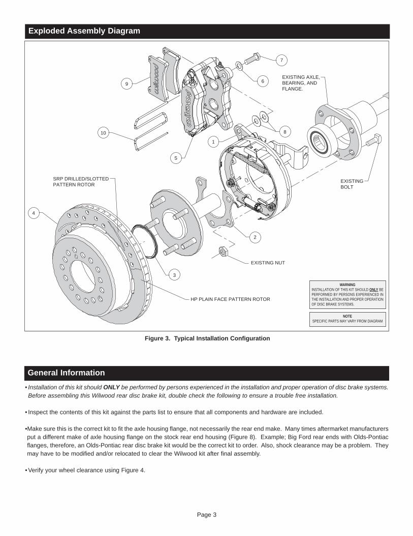
Exploded Assembly Diagram
10
4
8
3
6
2
7
9
1
5
SRP DRILLED/SLOTTEDPATTERN ROTOR
EXISTINGBOLT
EXISTING NUT
HP PLAIN FACE PATTERN ROTOR
EXISTING AXLE,BEARING, ANDFLANGE.
Figure 3. Typical Installation Configuration
WARNINGINSTALLATION OF THIS KIT SHOULD ONLY BEPERFORMED BY PERSONS EXPERIENCED INTHE INSTALLATION AND PROPER OPERATIONOF DISC BRAKE SYSTEMS.
NOTESPECIFIC PARTS MAY VARY FROM DIAGRAM
Page 3
General Information• Installation of this kit should ONLY be performed by persons experienced in the installation and proper operation of disc brake systems.Before assembling this Wilwood rear disc brake kit, double check the following to ensure a trouble free installation.
• Inspect the contents of this kit against the parts list to ensure that all components and hardware are included.
•Make sure this is the correct kit to fit the axle housing flange, not necessarily the rear end make. Many times aftermarket manufacturersput a different make of axle housing flange on the stock rear end housing (Figure 8). Example; Big Ford rear ends with Olds-Pontiacflanges, therefore, an Olds-Pontiac rear disc brake kit would be the correct kit to order. Also, shock clearance may be a problem. Theymay have to be modified and/or relocated to clear the Wilwood kit after final assembly.
•Verify your wheel clearance using Figure 4.
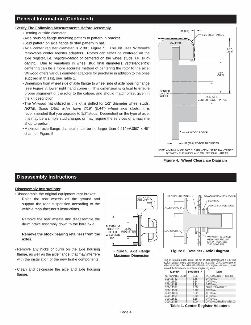
•Verify The Following Measurements Before Assembly.• Bearing outside diameter.• Axle housing flange mounting pattern to pattern in bracket.• Stud pattern on axle flange to stud pattern in hat.• Axle center register diameter is 2.80”, Figure 5. This kit uses Wilwood’sremovable center register adapters. Rotors can either be centered on theaxle register, i.e. register-centric or centered on the wheel studs, i.e. stud-centric. Due to variations in wheel stud final diameters, register-centriccentering can be a more accurate method of centering the rotor to the axle.Wilwood offers various diameter adapters for purchase in addition to the onessupplied in this kit, see Table 1.• Dimension from wheel side of axle flange to wheel side of axle housing flange(see Figure 8, lower right hand corner). This dimension is critical to ensureproper alignment of the rotor to the caliper, and should match offset given inthe kit description.• The Wilwood hat utilized in this kit is drilled for 1/2” diameter wheel studs.NOTE: Some OEM axles have 7/16” (0.44”) wheel axle studs. It isrecommended that you upgrade to 1/2” studs. Dependent on the type of axle,this may be a simple stud change, or may require the services of a machineshop to perform.•Maximum axle flange diameter must be no larger than 6.61” w/.050” x 45°chamfer, Figure 5.
Disassembly Instructions:•Disassemble the original equipment rear brakes:
Raise the rear wheels off the ground andsupport the rear suspension according to thevehicle manufacturer’s instructions.
Remove the rear wheels and disassemble thedrum brake assembly down to the bare axle.
Remove the stock bearing retainers from theaxles.
•Remove any nicks or burrs on the axle housingflange, as well as the axle flange, that may interferewith the installation of the new brake components.
•Clean and de-grease the axle and axle housingflange.
Page 4
Figure 4. Wheel Clearance Diagram
CENTERLINE OFWHEEL
1.25 (31,8) RADIUS.31 (7,9)
3.87(98,3)
6.57(166,9)
CALIPER
WILWOOD ROTOR
NOTE: A MINIMUM OF .080” CLEARANCE MUST BE MAINTAINED BETWEEN THE WHEEL AND CALIPER IN ALL AREAS
.81 (20,6) ROTOR THICKNESS
2.80 (71,1)CENTER REGISTRATION
General Information (Continued)
Disassembly Instructions
Figure 5. Axle FlangeMaximum Dimension
MAXIMUMDIA 6.61"TO FIT
WILWOODHAT
2.80”REGISTER
.050 X 45°CHAMFER
Figure 6. Retainer / Axle Diagram
BEARING RETAINER WILWOOD BACKING PLATE
BEARING
AXLE FLANGE
LUG STUDS
WILWOOD BEARINGRETAINER RELIEFSTEP TOWARDSTHE BEARING
AXLE FLANGE TUBE
Table 1. Center Register Adapters
This kit includes a 3.06” center I.D. hat or rotor assembly and a 2.80” hub register adapter ring to accommodate the installation of this kit on axles of either dimension. For axles with different center register diameters, please consult the table below for optional adapter ring sizes.
PART NO. REGISTER I.D. NOTENO ADAPTER USED300-11732300-11962300-11338300-11337300-11532300-11803300-11901300-11653300-11339
3.06”2.86”2.84”2.82”2.80”2.78”2.52”2.50”2.18”2.00”
ROTOR CENTER HOLE I.D.OPTIONALOPTIONALOPTIONALSUPPLIED WITH KITOPTIONALOPTIONALOPTIONALOPTIONALOPTIONAL (Machine to fit I.D.)
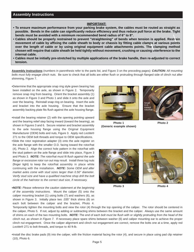
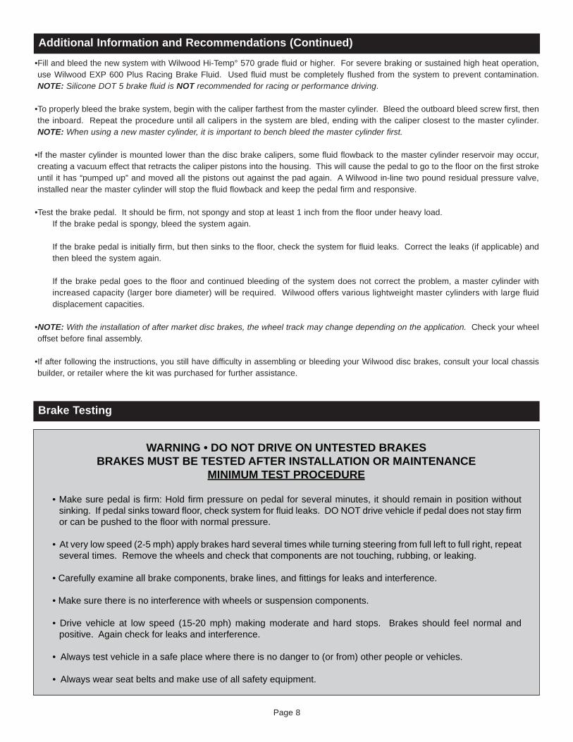
Assembly Instructions (numbers in parenthesis refer to the parts list, and Figure 3 on the preceding pages): CAUTION: All mountingbolts must fully engage clinch nuts. Be sure to check that all bolts are either flush or protruding through flanged side of clinch nut aftershimming, Figure 7.
•Determine that the appropriate snap ring style green bearing hasbeen installed on the axle, as shown in Figure 2. Temporarilyremove snap ring from bearing. Orient the bracket assembly (1)as shown in Figure 3 and Photo 1 and slide it onto the axle andover the bearing. Reinstall snap ring on bearing. Insert the axleand bracket into the axle housing. Ensure that the bracketassembly backing plate fits flush against the axle housing flange.
•Install the bearing retainer (2) with the opening pointing upwardand the bearing relief step facing inward (toward the bearing), asshown in Figures 3 and 6. Secure retainer and bracket assemblyto the axle housing flange using the Original EquipmentManufacturer (OEM) bolts and nuts, Figure 3. Apply red Loctite®271 to the OEM bolt threads and torque to OEM specifications. •Slide the rotor registration adapter (3) onto the axle register onthe axle flange with the smaller O.D. facing toward the rotor/hat(4), Photo 2. Align the correct hole pattern in the rotor/hat withthe stud pattern on the axle flange and slide into place, Figure 3and Photo 3. NOTE: The rotor/hat must fit flush against the axleflange or excessive rotor run out may result. Install three lug nuts(finger tight) to keep the rotor/hat assembly in place whilecontinuing with the installation. NOTE: Some OEM and aftermarket axles come with stud sizes larger than 0.50” diameter.Verify stud size and have a qualified machine shop drill the boltcircle of the hat/rotor to the correct stud size, if necessary.
•NOTE: Please reference the caution statement at the beginningof the assembly instructions. Mount the caliper (5) onto thecaliper mounting bracket (1) using bolts (7) and washers (6), asshown in Figure 3. Initially place two .035” thick shims (8) oneach bolt between the caliper and the bracket, Photo 4.Temporarily tighten the mounting bolts and view the rotor (4) through the top opening of the caliper. The rotor should be centered inthe caliper, Photo 5. If not, adjust by adding or subtracting shims between the bracket and the caliper. Always use the same amountof shims on each of the two mounting bolts. NOTE: The end of each bolt must be flush with or slightly protruding from the head of theclinch nut, as shown in Figure 7. If necessary place spare shims between washer (6) and caliper mounting ear to achieve the properclinch nut engagement. Once the caliper alignment and clinch nut engagement are correct, remove the bolts one at a time, apply redLoctite® 271 to bolt threads, and torque to 40 ft-lb.
•Install the disc brake pads (9) into the caliper, with the friction material facing the rotor (4), and secure in place using pad clip retainer(10), Photo 6.
Assembly Instructions
IMPORTANT:• To ensure maximum performance from your parking brake system, the cables must be routed as straight as
possible. Bends in the cable can significantly reduce efficiency and thus reduce pull force at the brake. Tight bends must be avoided with a minimum recommended bend radius of 6" to 8".
• Cables should be properly restrained to prevent "straightening" of bends when tension is applied. Restrain movement of cable by affixing the cable sheath to body or chassis by fitting cable clamps at various points over the length of cable or by using original equipment cable attachments points. The clamping method chosen will require that cable sheath be held tightly without movement, crushing or causing interference to the internal cable.
• Cables must be initially pre-stretched by multiple applications of the brake handle, then re-adjusted to correct tension.
Photo 1(Generic example shown)
Page 5
Photo 3 Photo 4
Photo 2
SmallO.D.towardrotor/hat
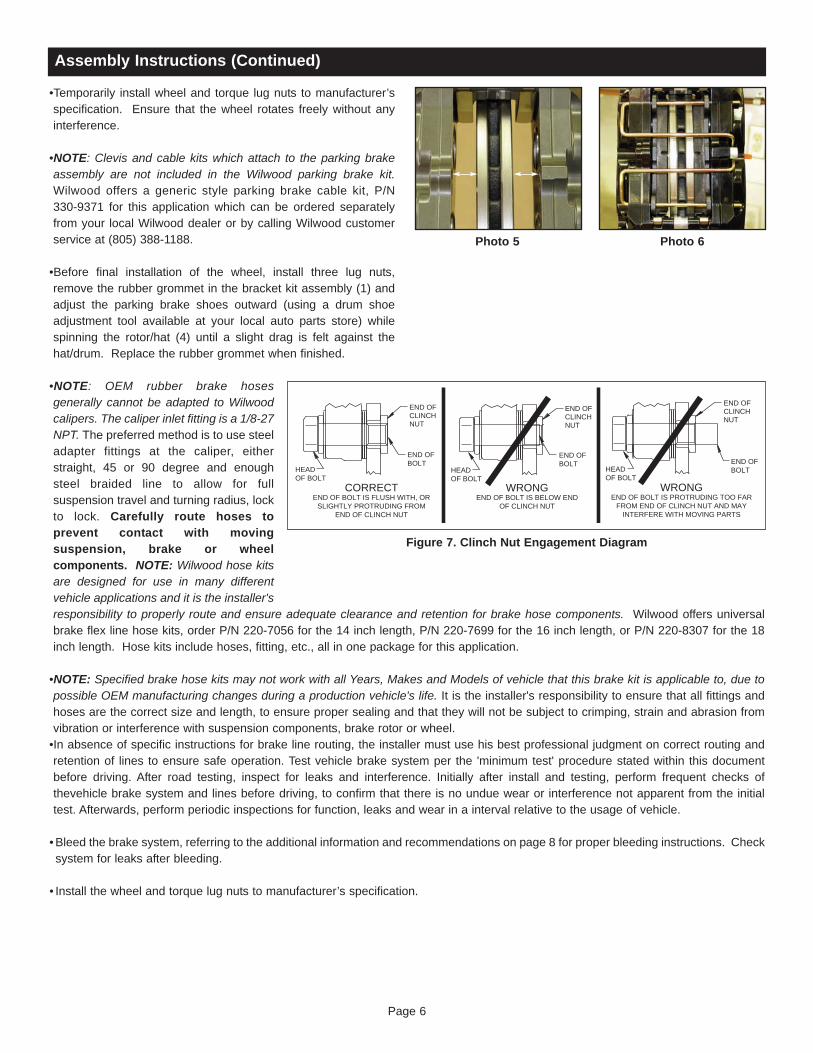
•Temporarily install wheel and torque lug nuts to manufacturer’sspecification. Ensure that the wheel rotates freely without anyinterference.
•NOTE: Clevis and cable kits which attach to the parking brakeassembly are not included in the Wilwood parking brake kit.Wilwood offers a generic style parking brake cable kit, P/N330-9371 for this application which can be ordered separatelyfrom your local Wilwood dealer or by calling Wilwood customerservice at (805) 388-1188.
•Before final installation of the wheel, install three lug nuts,remove the rubber grommet in the bracket kit assembly (1) andadjust the parking brake shoes outward (using a drum shoeadjustment tool available at your local auto parts store) whilespinning the rotor/hat (4) until a slight drag is felt against thehat/drum. Replace the rubber grommet when finished.
•NOTE: OEM rubber brake hosesgenerally cannot be adapted to Wilwoodcalipers. The caliper inlet fitting is a 1/8-27NPT. The preferred method is to use steeladapter fittings at the caliper, eitherstraight, 45 or 90 degree and enoughsteel braided line to allow for fullsuspension travel and turning radius, lockto lock. Carefully route hoses toprevent contact with movingsuspension, brake or wheelcomponents. NOTE: Wilwood hose kitsare designed for use in many differentvehicle applications and it is the installer'sresponsibility to properly route and ensure adequate clearance and retention for brake hose components. Wilwood offers universalbrake flex line hose kits, order P/N 220-7056 for the 14 inch length, P/N 220-7699 for the 16 inch length, or P/N 220-8307 for the 18inch length. Hose kits include hoses, fitting, etc., all in one package for this application.
•NOTE: Specified brake hose kits may not work with all Years, Makes and Models of vehicle that this brake kit is applicable to, due topossible OEM manufacturing changes during a production vehicle's life. It is the installer's responsibility to ensure that all fittings andhoses are the correct size and length, to ensure proper sealing and that they will not be subject to crimping, strain and abrasion fromvibration or interference with suspension components, brake rotor or wheel.•In absence of specific instructions for brake line routing, the installer must use his best professional judgment on correct routing andretention of lines to ensure safe operation. Test vehicle brake system per the 'minimum test' procedure stated within this documentbefore driving. After road testing, inspect for leaks and interference. Initially after install and testing, perform frequent checks ofthevehicle brake system and lines before driving, to confirm that there is no undue wear or interference not apparent from the initialtest. Afterwards, perform periodic inspections for function, leaks and wear in a interval relative to the usage of vehicle.
•Bleed the brake system, referring to the additional information and recommendations on page 8 for proper bleeding instructions. Checksystem for leaks after bleeding.
• Install the wheel and torque lug nuts to manufacturer’s specification.
Assembly Instructions (Continued)
Photo 5 Photo 6
Page 6
Figure 7. Clinch Nut Engagement Diagram
END OFBOLT
HEADOF BOLT
CORRECTEND OF BOLT IS FLUSH WITH, OR
SLIGHTLY PROTRUDING FROMEND OF CLINCH NUT
END OFCLINCHNUT
HEADOF BOLT
WRONGEND OF BOLT IS BELOW END
OF CLINCH NUT
END OFCLINCHNUT
END OFBOLT
HEADOF BOLT
WRONGEND OF BOLT IS PROTRUDING TOO FAR
FROM END OF CLINCH NUT AND MAYINTERFERE WITH MOVING PARTS
END OFCLINCHNUT
END OFBOLT

Assembly Instructions (Continued)
Figure 8. Rear Housing Flange Chart and Axle Flange / Offset Cross-Section
2.000
2.835 DIA
3/8”BOLT
3.336SMALL FORD
2.375
3.150 DIA
1/2”BOLT
3.500BIG FORD
2.000
3.150 DIA
3/8”BOLT
3.562
BIG FORD (NEW STYLE)
3/8”BOLT
2.000
3.562
SPEEDWAYENGINEERING
MODLITE
3/8”BOLT
1.680
TUBING O.D.2.840
3.076
3.410
8.8" FORD
8-3/4 AND 9-3/4MOPAR / DANA 60
3/8”BOLT
1.594
2.875 DIA
3.5622.203
3.188
2.000
2.560DIA
3.336
AMC
3/8”BOLT
3/8”BOLT
DANA 35
1.594
2.875DIA
TUBING O.D.2.600 - 2.8753.5622.203
3.188
OLDSPONTIAC
3/8”BOLT
2.375
3.150 DIA
2.875
3.500
CHEVY(SPECIAL)
3/8”BOLT
3.150DIA
2.404
2.652
3.072
3/8”BOLT
10 / 12 BOLTCHEVY
2.404
2.652
3.072
TUBING O.D. 2.725
3/8”BOLT
12 BOLT CHEVYC-CLIP ELIMINATOR
2.404
2.652
3.072
TUBING O.D. 2.725
3/8”BOLT
MARKWILLIAMS
3.000
3.150 DIA
3.000
3/8”BOLT
MUSTANG (05-UP)
3.746
TUBING O.D.3.190
2.304
AXLE FLANGE CROSS-SECTIONAXLE OFFSET
AXLE
AXLE HOUSINGFLANGE
AXLE TUBE
AXLEFLANGE
WHEELSTUD
TUBINGO.D. 3.420
1955-1957 CHEVY1956 CORVETTE
2.656
3.396
2.835 DIA (1955/56)3.000 DIA (1957)
3/8” BOLT
3/8”BOLT
2.404
2.652
3.072
TUBING O.D. 2.840
12 BOLT-LATECHEVY
TUBINGO.D. 3.420
1957-1962 CORVETTE1959-1964 IMPALA
2.656
3.396
3.000 DIA
3/8”BOLT
3/8”BOLT
2.531DIA
CHEVYC10
2.656
3.396
TUBING O.D.3.420
3/8”BOLT
STRANGEENGINEERING
FLOATER AXLE
1.750
2.373DIA
3.030
3/8”BOLTTUBING
O.D. 2.685 2.87
7-1/4” FORD
3.23
1.680
Page 7
Additional Information and Recommendations•Please read the following concerning balancing the brake bias on 4 wheel disc vehicles.
•OE Style or Single Mount Race Pedal with Tandem Outlet Master Cylinder:Front to rear caliper piston sizes, rotor diameters, and pad compounds must be initially configured to provide the correct range ofvehicle bias when using a single bore / tandem outlet master cylinder. If excessive rear brake bias is experienced, an inline adjustableproportioning valve can be used to decrease the rear line pressure to help bring the vehicle into balance. If excessive front brake biasis experienced, first consideration should be given to increasing the rear brake bias to bring the vehicle into overall balance.
•Race Pedal with Dual Master Cylinders and Balance Bar:Master cylinders must be sized to match the calipers and allow the pedal balance bar to operate near the center of its travel. If it is notpossible to fine tune the bias within the adjustable range of the balance bar, then consideration must be given to changing a mastercylinder bore size or some other aspect of the brake system to bring the car into balance. Larger bore master cylinders will generateless pressure while decreasing pedal travel. Smaller bores master cylinders will generate higher line pressures with an increase inpedal travel.
Additional Information and Recommendations (Continued)
Page 8
•Fill and bleed the new system with Wilwood Hi-Temp° 570 grade fluid or higher. For severe braking or sustained high heat operation,use Wilwood EXP 600 Plus Racing Brake Fluid. Used fluid must be completely flushed from the system to prevent contamination.NOTE: Silicone DOT 5 brake fluid is NOT recommended for racing or performance driving.
•To properly bleed the brake system, begin with the caliper farthest from the master cylinder. Bleed the outboard bleed screw first, thenthe inboard. Repeat the procedure until all calipers in the system are bled, ending with the caliper closest to the master cylinder.NOTE: When using a new master cylinder, it is important to bench bleed the master cylinder first.
•If the master cylinder is mounted lower than the disc brake calipers, some fluid flowback to the master cylinder reservoir may occur,creating a vacuum effect that retracts the caliper pistons into the housing. This will cause the pedal to go to the floor on the first strokeuntil it has “pumped up” and moved all the pistons out against the pad again. A Wilwood in-line two pound residual pressure valve,installed near the master cylinder will stop the fluid flowback and keep the pedal firm and responsive.
•Test the brake pedal. It should be firm, not spongy and stop at least 1 inch from the floor under heavy load.If the brake pedal is spongy, bleed the system again.
If the brake pedal is initially firm, but then sinks to the floor, check the system for fluid leaks. Correct the leaks (if applicable) andthen bleed the system again.
If the brake pedal goes to the floor and continued bleeding of the system does not correct the problem, a master cylinder withincreased capacity (larger bore diameter) will be required. Wilwood offers various lightweight master cylinders with large fluiddisplacement capacities.
•NOTE: With the installation of after market disc brakes, the wheel track may change depending on the application. Check your wheeloffset before final assembly.
•If after following the instructions, you still have difficulty in assembling or bleeding your Wilwood disc brakes, consult your local chassisbuilder, or retailer where the kit was purchased for further assistance.
Brake Testing
• Make sure pedal is firm: Hold firm pressure on pedal for several minutes, it should remain in position without sinking. If pedal sinks toward floor, check system for fluid leaks. DO NOT drive vehicle if pedal does not stay firm or can be pushed to the floor with normal pressure.
• At very low speed (2-5 mph) apply brakes hard several times while turning steering from full left to full right, repeat several times. Remove the wheels and check that components are not touching, rubbing, or leaking.
• Carefully examine all brake components, brake lines, and fittings for leaks and interference.
• Make sure there is no interference with wheels or suspension components.
• Drive vehicle at low speed (15-20 mph) making moderate and hard stops. Brakes should feel normal and positive. Again check for leaks and interference.
• Always test vehicle in a safe place where there is no danger to (or from) other people or vehicles.
• Always wear seat belts and make use of all safety equipment.
WARNING • DO NOT DRIVE ON UNTESTED BRAKESBRAKES MUST BE TESTED AFTER INSTALLATION OR MAINTENANCE
MINIMUM TEST PROCEDURE
Page 9
Pad and Rotor Bedding
BEDDING STEPS FOR NEW PADS AND ROTORS – ALL COMPOUNDSOnce the brake system has been tested and determined safe to operate the vehicle, follow these steps for the bedding of all new padmaterials and rotors. These procedures should only be performed on a race track, or other safe location where you can safely andlegally obtains speeds up to 65 MPH, while also being able to rapidly decelerate.
• Begin with a series of light decelerations to gradually build some heat in the brakes. Use an on-and-off the pedal technique byapplying the brakes for 3-5 seconds, and then allow them to fully release for a period roughly twice as long as the deceleration cycle.If you use a 5 count during the deceleration interval, use a 10 count during the release to allow the heat to sink into the pads androtors.
• After several cycles of light stops to begin warming the brakes, proceed with a series of medium to firm deceleration stops tocontinue raising the temperature level in the brakes.
• Finish the bedding cycle with a series of 8-10 hard decelerations from 55-65 MPH down to 25 MPH while allowing a proportionaterelease and heat-sinking interval between each stop. The pads should now be providing positive and consistent response.
• If any amount of brake fade is observed during the bed-in cycle, immediately begin the cool down cycle. • Drive at a moderate cruising speed, with the least amount of brake contact possible, until most of the heat has dissipated from thebrakes. Avoid sitting stopped with the brake pedal depressed to hold the car in place during this time. Park the vehicle and allow thebrakes to cool to ambient air temperature.
COMPETITION VEHICLES• If your race car is equipped with brake cooling ducts, blocking them will allow the pads and rotors to warm up quicker and speed upthe bedding process.
• Temperature indicating paint on the rotor and pad edges can provide valuable data regarding observed temperatures during thebedding process and subsequent on-track sessions. This information can be highly beneficial when evaluating pad compounds andcooling efficiencies.
POST-BEDDING INSPECTION – ALL VEHICLES• After the bedding cycle, the rotors should exhibit a uniformly burnished finish across the entire contact face. Any surface irregularitiesthat appear as smearing or splotching on the rotor faces can be an indication that the brakes were brought up to temperature tooquickly during the bedding cycle. If the smear doesn’t blend away after the next run-in cycle, or if chatter under braking results,sanding or resurfacing the rotors will be required to restore a uniform surface for pad contact.
PRE-RACE WARM UP• Always make every effort to get heat into the brakes prior to each event. Use an on-and-off the pedal practice to warm the brakesduring the trip to the staging zone, during parade laps before the flag drops, and every other opportunity in an effort to build heat inthe pads and rotors. This will help to ensure best consistency, performance, and durability from your brakes.
DYNO BEDDED COMPETITION PADS AND ROTORS• Getting track time for a proper pad and rotor bedding session can be difficult. Wilwood offers factory dyno-bedded pads and rotorson many of our popular competition pads and Spec 37 GT series rotors. Dyno-bedded parts are ready to race on their first warmup cycle. This can save valuable time and effort when on-track time is either too valuable or not available at all, Dyno-beddingassures that your pads and rotors have been properly run-in and are ready to go. Contact your dealer or the factory for moreinformation on Wilwood Dyno-Bedding services.
NOTE:NEVER allow the contact surfaces of the pads or rotors to be contaminated with brake fluid. Always use a catch bottle with a hose toprevent fluid spill during all brake bleeding procedures.

DS-776E REV DATE: 08-09-13
260-1874260-1876260-8419290-0632290-6209340-1285340-1287260-6764260-6765260-6766260-4893250-2406260-8555260-8556350-2038270-2016270-2017220-7056220-7699220-8307
Wilwood Residual Pressure Valve (2 lb for disc brakes)Wilwood Residual Pressure Valve (10 lb for drum brakes)Wilwood Proportioning ValveWilwood Racing Brake Fluid (Hi-Temp° 570) (12 oz)Wilwood Racing Brake Fluid (EXP 600 Plus) (16.9 oz)Wilwood Floor Mount Brake Pedal (with balance bar)Wilwood Swing Mount Brake Pedal (with balance bar)Wilwood 3/4 inch High Volume Aluminum Master CylinderWilwood 7/8 inch High Volume Aluminum Master CylinderWilwood 1 inch High Volume Aluminum Master Cylinder1-1/16 inch Tandem Master Cylinder (aluminum housing)Mounting Bracket Kit (tandem master cylinder)Wilwood 1 inch Aluminum Tandem Chamber Master CylinderWilwood 1-1/8 inch Aluminum Tandem Chamber Master Cylinder1971 - 1973 Pinto Rack and Pinion (new, not rebuilt)Quick Release Steering Hub (3/4 inch shaft)Quick Release Steering Hub (5/8 inch shaft)Flexline Kit, Universal, 14 Inch, DomesticFlexline Kit, Universal, 16 Inch, DomesticFlexline Kit, Universal, 18 Inch, Domestic
Associated ComponentsPART NO. DESCRIPTION
www.wilwood.com • E-mail Technical Assistance: [email protected] Disc Brakes • 4700 Calle Bolero, Camarillo, CA 93012 Phone 805 / 388-1188 • Fax 805 / 388-4938
Parking Brake
• Parking brake must be properly adjusted before use and must be manually readjusted for wear if parking brake handle or foot lever travel becomes excessive.
• The holding ability of the brake should be tested by stopping on a sloping surface and applying the parking brake while holding car with the hydraulic foot brake. This should be accomplished both facing up and down hill.
• Do not rely exclusively on the parking brake to hold the car; Curb wheels as recommended by the applicable diagram and put gear selector in park, or shift into first gear or reverse with a manual transmission.
• Diagram A - When parking facing downhill, turn front wheels towards the curb or right shoulder. This will keep from rolling into traffic if the brakes become disengaged.
• Diagram B - Turn the steering wheel to the left so the wheels are turned towards the road if you are facing uphill with a curb. The tires will catch the curb if the car rolls backward.
• Diagram C - When facing uphill without a curb, turn the wheels sharply to the right. If the vehicle rolls, it will go off the road rather than into traffic.
• When parking on a hill, always set the parking brake and move the gear selector into park, or shift into first or reverse gear if your vehicle has a manual transmission.
WARNING • PARKING BRAKE
DOWNHILLwith curb
Turn WheelsTo Curb
Diagram A
UPHILLwith curb
Turn WheelsFrom Curb
Diagram B
UPHILLwithout curb
Turn WheelsTo Right
Diagram C
Connect with Wilwood
Wilwood Social Forum Wilwood Facebook Wilwood Twitter Wilwood YouTube
Related Documents