ASSEMBLY INSTRUCTIONS PVC PORTAL aluplast Smart-Slide ES Window systems Door systems Comfort systems

Welcome message from author
This document is posted to help you gain knowledge. Please leave a comment to let me know what you think about it! Share it to your friends and learn new things together.
Transcript
ASSEMBLY INSTRUCTIONSPVC
PORTAL
aluplast Smart-Slide
ES
Window systems
Door systems
Comfort systems

H48.ESKFK0003EN 11.2019 3/40
Content
Content
1 GENERAL NOTES ........................................4
1.1 Target group of this documentation ............. 41.2 Copyright ....................................................... 41.3 Directives of the Trade Organisation for Locks
and Fittings (Gütegemeinschaft Schlösser und Beschläge e.V.) ............................................... 4
1.4 Information and instruction obligations........ 41.5 Dimensions ................................................... 4
2 SAFETY .......................................................5
2.1 Intended use ................................................. 52.2 Improper use ................................................. 52.3 Safety notes .................................................. 5
3 OPERATING AND INSTALLATION INFORMATION .....................................................7
3.1 Handle operation .......................................... 73.2 Abbreviations and dimensions ...................... 73.3 Description of symbols .................................. 83.4 Screws .......................................................... 8
4 PROCESSING SPECIFICATIONS ..................9
4.1 Size ranges..................................................... 94.2 Scheme versions ........................................... 9
5 HARDWARE COMPONENTS.....................10
5.1 Hardware demonstration scheme A ........... 105.2 Hardware list components .......................... 115.3 Accessories hardware components ............ 125.4 Handle overview ......................................... 13
6 ASSEMBLY OF FRAME ELEMENT .............14
6.1 Striker packer and guiding rail ..................... 146.2 Running rail (LL) .......................................... 156.3 Guide strikers .............................................. 166.4 Frame part MV ............................................ 176.4.1 Adjustment options frame part MV ................... 186.5 Stop ............................................................. 196.6 Adapter rail ................................................. 206.7 Hook striker (HH)......................................... 21
6.8 Central lock striker (HM) ............................. 22
7 INSTALLATION OF SASH ELEMENT ..........23
7.1 Adapter profile Eurogroove......................... 237.1.1 Position of the screw holes ................................. 247.2 Adapter profile ............................................ 257.3 Guiding elements ........................................ 257.4 Bogie wheels ES .......................................... 267.5 Sash part MV horizontal .............................. 277.6 Gear ............................................................ 287.6.1 Milling and drilling .............................................. 287.6.2 Fixing the gear box ............................................. 297.6.3 Fixing the PZ gear box - optional ........................ 297.6.4 Locking bolt VS ................................................... 297.7 Central lock MP ........................................... 307.8 Inserting the sliding sash ............................. 317.9 Removing the sliding sash ........................... 327.10 Adjustment of sliding sash .......................... 337.10.1 Adjustment of top guiding elements .................. 337.10.2 Adjustment of bottom guiding elements ........... 33
8 PROFILE SECTIONS ..................................34
8.1 SI construction drawings ............................. 34
9 DRILLING AND MILLING JIGS ..................35
10 MAINTENANCE ........................................36
10.1 Cleaning and maintenance .......................... 36
11 NOTES ......................................................37

PORTAL aluplast Smart-SlideGeneral notes
ES
11.20194/40 H48.ESKFK0003EN
1 General notes
1.1 Target group of this documentation
This documentation is intended for use by specialists only.
All work described in this document is to be performed only by experienced professionals with training and practice in the assembly, commissioning as well as the servicing and maintenance of PORTAL hardware. The safe and appropriate installation of the PORTAL hardware is not possible without specialist expertise.
Keep these assembly instructions in a safe place so that you have quick access to them in case of need.
1.2 Copyright
The contents of these instructions are protected by copyright. Their use is permissible in the scope of the further processing of the hardware components. Any use beyond this definition is inadmissible without the prior written consent of the manufacturer.
1.3 Directives of the Trade Organisation for Locks and Fittings (Gütegemeinschaft Schlösser und Beschläge e.V.).
The directives of the Trade Organisation for Locks and Fittings provide comprehensive information on the correct operation and maintenance of hardware for windows and patio doors. It is mandatory to adhere to these directives.
You can find the latest versions of the directives here in a range of languages:http://www.beschlagindustrie.de/ggsb/richtlinien.asp
VHBH – Hardware for windows and patio doorsGuidelines and notes on the product and on liability
VHBE – Hardware for windows and patio doors
Guidelines and notes for end users
The VHBH also contains information concerning „instruction obligation“. The "instruction obligation information concerning which documents and information must be handed out by/to the relevant target groups.
1.4 Information and instruction obligations
The following documents are available for the performance of the information and instructions obligations and must be be handed out to every (intermediate) retailer and fabricator and subsequently to the end customer as well as for the performance of maintenance work:
• Planning documents• Product catalogues• Assembly instructions• SI construction drawings• Maintenance and service instructions• Operating instructions
You can find the latest versions of the documents here in a range of languages:https://downloads.siegenia.com/en/
You can obtain the SI construction drawings from SIEGENIA customer service.
1.5 Dimensions
All dimensions are nominal values and include the general tolerances (formerly "dimensional variations"). All nominal values are given in mm.
aluplast Smart-Slidesafety
PORTAL
ES
H48.ESKFK0003EN 11.2019 5/40
2 safety
2.1 Intended use
The PORTAL ES hardware is designed only for use in windows or patio doors with a maximum sash weight of 250 kg.
The PORTAL ES hardware allows the horizontal opening and closing of windows and patio doors from profiles for windows and patio doors.The windows or patio doors made of timber, PVC, aluminium or steel and corresponding material composites must be installed vertically, in no circumstances in a sloping position.
The windows and patio doors must be equipped with a corresponding drainage system. The elements may not be installed without providing appropriate drainage and weather protection.
Intended use comprises the adherence to all information provided in product-specific documents such as:
• These assembly instructions• SI construction drawings• Product catalogues• Information, information from the profile
manufacturer (e. g. for PVC or light metal profiles)• Directives VHBE of the Trade Organisation for Locks
and Fittings (Gütegemeinschaft Schlösser und Beschläge e.V.).
• Valid, national laws and regulations
Any use beyond the defined intended use is regarded as misuse.
2.2 Improper use
– When obstacles are placed in the opening range and thus impede the intended use
– When window and patio door sashes are pressed or even banged improperly or in an uncontrolled manner (e.g. by wind) against window reveals in such a way that either the hardware or the frame materials or other individual window parts could be damaged or destroyed, or consequential damage could occur
– When additional loads have an impact on window or patio door sashes (for example, when children rock on the window or patio door sashes)
– If hands are placed in the rebate between the
frame and sash when closing windows (risk of injury)
2.3 Safety notes
DANGER
Danger to life due to sliding sash falling out.
Damage or deformation could occur on the guiding or window elements during transportation or installation of the window or patio door, which could lead to breakage of the guiding elements and to the sash falling out when it is opened.
• Secure the sliding sashes against falling out of the running rail throughout the entire transport route until they are installed in the building.
• Following installation of the element, ensure the following:– The bogie wheels are guided over the entire
sliding track on the running rail.– The guiding elements interlock completely
along the entire sliding distance in the guide track.
The PORTAL ES hardware must not be used in the following cases:
– in damp locations– in environments where the air contains
aggressive, corrosive components– in environments where the air contains salt
Windows or patio doors for wet rooms and for use in environments with aggressive, corrosive air need a hardware which meets the special requirements.Please contact your SIEGENIA sales consultant in such situations.
Avoid exposing the hardware directly to water and do not let cleaning agents come into contact with the hardware.
The complete set of hardware may only be composed of original SIEGENIA hardware components. We assume no liability if non-original or non-approved system accessory parts are used.
PORTAL aluplast Smart-Slidesafety
ES
11.20196/40 H48.ESKFK0003EN
WARNING
Risk of injury due to misuse and inappropriate assembly of the hardware.
• Only use hardware combinations which have been approved by the hardware manufacturer.
• Only use original accessory parts or which have been approved by the hardware manufacturer.
Do not use acid-releasing sealants to seal the windows or patio doors. These may cause the corrosion of hardware components. Window and patio doors may only be surface treated before installing the hardware components. Treating these surfaces at a later stage can reduce the functional capacity of the hardware components. We assume no liability in this case.
Keep the track of the running rail and all rebates free from
– cement or plaster residues– debris – dirt

aluplast Smart-SlideOperating and installation information
PORTAL
ES
H48.ESKFK0003EN 11.2019 7/40
3 Operating and installation information
3.1 Handle operation
Release and sliding of the sliding sash.
Sliding sash locking position.
Sliding sash gap ventilation night vent.
3.2 Abbreviations and dimensions
AB Stop interval
FBS Sliding sash width
FFB Sash rebate width
FFH Sash rebate height
FHS Sliding sash height
HF1 Height of central lock for sash part (central area) 1
HF2 Height of sash part central lock (central area) 2
HF3 Height of sash part central lock (central area) 3
HH1 Height of hook striker 1
HH2 Height of hook striker 2
HR1 Height of frame part central lock (central area) 1
HR2 Height of frame part central lock (central area) 2
HR3 Height of frame part central lock (central area) 3
HM1 Height of central lock (locking side) 1
HM2 Height of central lock (locking side) 2
HM3 Height of central lock (locking side) 3
LD1 Length of distance rail 1
LD2 Length of distance rail 2
LL Length of running rail
LS Length of rail SOFT CLOSE
LTW Length of horizontal supporting profile
LTS Length of vertical supporting profile
MV1 Interval horizontal central lock 1
MV2 Interval horizontal central lock 2
MVF1 Interval central lock horizontal sash 1
MVF2 Interval central lock horizontal sash 2
RTB Width of frame supporting rails
RTH Height of frame supporting rails
ST1 Interval guide striker 1
ST2 Interval guide striker 2
VE Packaging unit
VB Interval central post sliding sash
PORTAL aluplast Smart-SlideOperating and installation information
ES
11.20198/40 H48.ESKFK0003EN
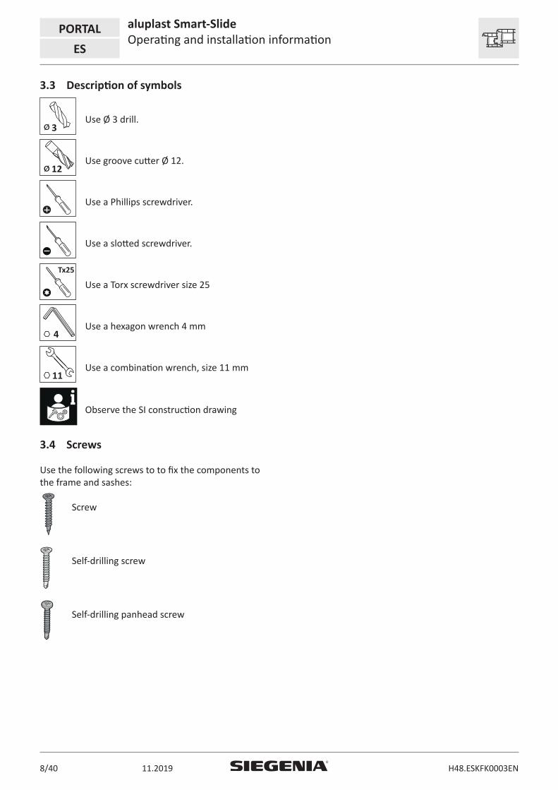
3.3 Description of symbols
ø 3Use Ø 3 drill.
ø 12Use groove cutter Ø 12.
Use a Phillips screwdriver.
Use a slotted screwdriver.
Tx25
Use a Torx screwdriver size 25
4Use a hexagon wrench 4 mm
11Use a combination wrench, size 11 mm
Observe the SI construction drawing
3.4 Screws
Use the following screws to to fix the components to the frame and sashes:
Screw
Self-drilling screw
Self-drilling panhead screw

aluplast Smart-SlideProcessing specifications
PORTAL
ES
H48.ESKFK0003EN 11.2019 9/40
4 Processing specifications
To comply with the requirements of EN13126-16, a handle length of 160 mm must be used.
The components of the lift and slide element must be stored at room temperature (20°C) for 24 hours before processing.
For adhesion and sealing work, we recommend
– OTTO Chemie-OTTOSEAL® S 72– Collano Adhesives AG-Collano® A 1970– or a similar product
The PORTAL ES hardware in this documentation is designed for the aluplast Smart-Slide system. Subsequent adjustments can be made due to the system dimensions influenced by the hardware. If a deviation from the system dimensions is only detected after the installation in the window, the hardware manufacture will not be liable for any additional expenditure incurred.
4.1 Size ranges
Profile design White Application diagram max. 150 kgFFH
[mm
]
2.000
1.500
1.000
FFB [mm]1.000 1.500 2.000
GG [kg/m²]
70 60 50 40 30Frame width (RAB) 1018 – 4000
Frame height (RAH) 738 – 2414
Sash rebate width (FBS) 472 – 1500
Sash height of sliding sash (FHS) 624 – 2300
Sash weight max. 150 kg
4.2 Scheme versions
Possible scheme versions:
– Scheme A– Scheme K
The corresponding SI construction drawings are
available.
Further versions only after release and sash determination by the profile manufacturer.

PORTAL aluplast Smart-SlideHardware components
ES
11.201910/40 H48.ESKFK0003EN
5 Hardware components
5.1 Hardware demonstration scheme A
26 E E E6
4
12
8
9
9
5
14
14
15
A
A
B
A
C
D EE E
C
8
5
7 2
5
1 4
73 3 12
10
13
13
11
1
17
16
5

aluplast Smart-SlideHardware components
PORTAL
ES
H48.ESKFK0003EN 11.2019 11/40
5.2 Hardware list components
Item Pieces Material designation Material number
1 Horizontal central lock ES from FBS > 800 PZUN0150-10001_
1 2 Sash part MV horizontal ES aluplast
2 2 Frame part ES MV horizontal
3 2 Bogie wheels ES PLWN0020-09901_
4 2 Adapter profile ES aluplast Size Length
150 1500 PPAN0010-50001_
5 2 Guiding element Z5 PFEN4000-10001_
6 2 Guide striker PRFN0010-10001_
7 2 Guide striker holes PRFN0020-10001_
8 2 Hook striker 3x2 PRHN0010-10001_
9 4 Packer hook striker ES PUZN0020-X0006_
1 Gear set 40 M5 PMSN0010-10001_
10 1 Gear box 40 M5
11 2 Countersunk screw M4 x 11
12 2 Stop PABN0010-10001_
13 1-3 Locking bolt VS adjustable PVBN0020-02301_
14 1-3 Striker locking side ES PR PSTN0040-02301_
15 1 Central lock MP ES aluplast Size Length
230 2300 PPMN0010-52401_
16 1 Gear 25-55 A.D. SizeHandle position
60- 80 80-100100-120120-200170-250
300400500500
1000
PGKN0500-10001_PGKN0400-10001_PGKN0300-10001_PGKN1080-10001_PGKN0250-10001_
17 1 Extension Sizes
170-190190-210
210-230230-250
PGVN0010-10001_PGVN0020-10001_
aluplast profiles
Item Pieces Material designation aluplast number
A 3 Adapter profile Eurogroove 207282
B 1 Top guiding rail 207284
C 2 Striker packer running rail and adapter rail 207283
D 1 Running rail 207285
E 7 Adapter rail 207286

PORTAL aluplast Smart-SlideHardware components
ES
11.201912/40 H48.ESKFK0003EN
5.3 Accessories hardware components
19
18 20
ItemVE per sliding
sashMaterial designation
Content per VE
Material number
1 Gear set PZ 40 for profile cylinder PSLN0010-10001_
18 Gear box PZ 40 1
19 Countersunk screw M4x11 ST H DIN 7500 2
1 Gear set PZ22 40 for round cylinder PSLN0020-10001_
20 Gear box PZ22 40 1
19 Countersunk screw M4x11 ST H DIN 7500 2

aluplast Smart-SlideHardware components
PORTAL
ES
H48.ESKFK0003EN 11.2019 13/40
5.4 Handle overview
Item Pieces Material description Colour Material number
H1 Handle Si-line PSK 45
RAL 9003RAL 8022EV 1 silver
PHIJ0040-50201_PHIJ0040-51201_PHIJ0040-02501_
H2 Handle Si-line PSK 45 lockable
RAL 9003RAL 8022EV 1 silver
PHIJ0050-50201_PHIJ0050-51201_PHIJ0050-02501_
H2 2 Countersunk head screw M5x65
KDNA0070-100010for handle Si-line
H3 Recessed pull handle Si-line
RAL 9003RAL 8022
Silver
PSMB0040-00201_PSMB0040-51201_PSMB0040-02501_
12
Sliding gripchipboard screw 3x12
H4 Handle Si-line ES outside set
RAL 9003RAL 8022EV1 silver
PHAN0010-50201_PHAN0010-52101_PHAN0010-52401_
1111122
Handle Si-line PSK without squareBag of cover caps PZHandle Si-line PSK outside flatRose Si-line PZ outsideSquare spindle 7x7x135Countersunk head screw M5x80Countersunk head screw M5x85

PORTAL aluplast Smart-SlideAssembly of frame element
ES
11.201914/40 H48.ESKFK0003EN
6 Assembly of frame element
6.1 Striker packer and guiding rail
2
2
1
2
1
1 Top guiding rail
2 Support rail
Rail positions on the frame.
1
3.9x25
1x
4
Crop rails to the required lengths and position in frame. Screw rails in the frame. Use drill screw 3.9x25

aluplast Smart-SlideAssembly of frame element
PORTAL
ES
H48.ESKFK0003EN 11.2019 15/40
6.2 Running rail (LL)
1 2
Crop the running rail to the required length (LL). Position the running rail in the support rail.
3 3.9x16
1x
4
Screw holes in the running rail recesses. Screw the running rail in the support rail. Use drill screw 3.9x16

PORTAL aluplast Smart-SlideAssembly of frame element
ES
11.201916/40 H48.ESKFK0003EN
6.3 Guide strikers (primarily for ECO SLIDE)
1 2
1 Drill screw 3.9x16
2 Drill screw 3.9x25
Fix the guide striker at two different lengths with drill screw.
1 2 3.9x25
2x
Mounting position of the initial guide strikers (ST1) on the frame. Observe the SI construction drawing.
Fix the guide strikers (ST1) in the support rail and the top guiding rail. Use corresponding drill screw.
3 4 3.9x25
2x
ST2
Mounting position of the second guide strikers (ST2) on the frame. Observe the SI construction drawing.
Fix the guide strikers (ST2) in the support rail and the top guiding rail. Use corresponding drill screw.

aluplast Smart-SlideAssembly of frame element
PORTAL
ES
H48.ESKFK0003EN 11.2019 17/40
6.4 Frame part MV
A frame part MV must be mounted from a sliding sash width of 800 mm.
1
ø 3
2
Mark the mounting position of the fame part MV (MV) on the support rail and the top guiding rail. Observe the SI construction drawing.
Adjust the stop marking of the jig to the marking. Drill the screw holes and mortises for frame part MV (MV).
3
MV MV
4
Pay attention to the adjustment of the jig. Pay attention to the correct adjustment when positioning the frame part MV (MV) in the support rail and the top guiding rail. The arrows indicate the locking direction.
5
3.9x252x
6
Fix the frame part MV (MV) in the support rail and the top guiding rail. Use drill screw 3.9x25.
Do not fix the pressure bolt until the sliding sash has been inserted. Push the pressure bolt against the locking direction as far as the stop.

PORTAL aluplast Smart-SlideAssembly of frame element
ES
11.201918/40 H48.ESKFK0003EN
7
2.1.4
8
2 mm
1. Close sliding sash as far as the stop on the hook striker.
2. Open the sliding sash again.
Push back the pressure bolt 2 mm in the locking direction and fix with a adjusting screw.
6.4.1 Adjustment options frame part MV
4
1 mm
1 mm
Pressure adjustment by +/- 1 mm. Height adjustment by 2 mm with screwdriver.

aluplast Smart-SlideAssembly of frame element
PORTAL
ES
H48.ESKFK0003EN 11.2019 19/40
6.5 Stop
WARNING
Danger of injury if the stop/stopper of the sliding sash is missing.
When the sliding sash is opened, a shearing zone arises between the sliding sash and the fixed sash. Bodily parts could be severed or crushed in the shearing zone.
• Mount a stop/stopper for the sliding sash. A shearing zone will hence be prevented.
Min. 20
A
B
A Sliding sash
B Fixed sash
Select the position for the stop to ensure that a gap of of 20 mm is maintained in the shearing zone.
1
øø8ø3
2
Mounting position of the stop on the frame. Observe the SI construction drawing.
Adjust the stop marking of the jig to the marking. Drill the screw holes and mortises for frame part MV (MV).
3
AB AB
4
4.1x222x
Pay attention to the adjustment of the jig. Position the stop in the support rail and the top guiding rail. Fixing only after mounting the adapter rail.

PORTAL aluplast Smart-SlideAssembly of frame element
ES
11.201920/40 H48.ESKFK0003EN
6.6 Adapter rail
1
LD3
LD1
LD3
LD2
LD2
2
Required lengths LD between the frame parts. See SI construction drawing for cutting size (LD).
Cut and adapt the adapter rails to the required lengths.
3 4
Support rail
Top guiding rail
Position the adapter rails of the support rail and top guiding rail.
3
3.9x25
3
Screw holes in the running rail recesses. Screw the adapter rails of the support rail and top guiding rail into place. Use drill screw 3.9x25.
aluplast Smart-SlideAssembly of frame element
PORTAL
ES
H48.ESKFK0003EN 11.2019 21/40
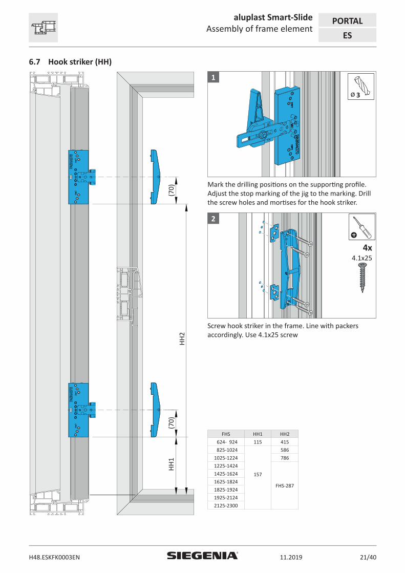
6.7 Hook striker (HH)
HH
1 (7
0)(7
0)
HH
2
ø 3
1
Mark the drilling positions on the supporting profile. Adjust the stop marking of the jig to the marking. Drill the screw holes and mortises for the hook striker.
4.1x254x
2
Screw hook striker in the frame. Line with packers accordingly. Use 4.1x25 screw
FHS HH1 HH2
624- 924 115 415
825-1024
157
586
1025-1224 786
1225-1424
FHS-287
1425-1624
1625-1824
1825-1924
1925-2124
2125-2300

PORTAL aluplast Smart-SlideAssembly of frame element
ES
11.201922/40 H48.ESKFK0003EN
6.8 Central lock striker (HM)
HM
1(7
0)(7
0)(7
0)
HM
2H
M3
ø 3
1
Mark the drilling positions on the supporting profile. Adjust the stop marking of the jig to the marking. Drill the screw holes and mortises for central lock hook striker.
3.9x252x
2
Screw the central lock striker in the frame. Use drill screw 3.9x25
FHS HM1 HM2 HM2
624- 924 – – –
825-1024 417 – –
1025-1224 592 – –
1225-1424 617 – –
1425-1624 317 FHS-607 –
1625-1824 617 FHS-607 –
1825-1924 532 1117 –
1925-2124 532 1117 FHS-277
2125-2300 532 1117 FHS-277

aluplast Smart-SlideInstallation of sash element
PORTAL
ES
H48.ESKFK0003EN 11.2019 23/40
7 Installation of sash element
7.1 Adapter profile Eurogroove
1
Mounting position of the adapter profile Eurogroove on the sliding sash. See SI construction drawing for length of the adapter profile Eurogroove(LAE).
Positioning the adapter profile Eurogroove in the sliding sash.
2
øø4
3
Positioning the adapter profile Eurogroove in the sliding sash.
Use the PABB4060 jig to drill the fixing holes.
4
3.9x38
Fix adapter profile Eurogroove in the sash profile with drill screw 3.9x38.

PORTAL aluplast Smart-SlideInstallation of sash element
ES
11.201924/40 H48.ESKFK0003EN
7.1.1 Position of the screw holes
250
50
250
A
Screw holes recesses
B
AArea of the subsequent hook position
BArea of the subsequent gear position

aluplast Smart-SlideInstallation of sash element
PORTAL
ES
H48.ESKFK0003EN 11.2019 25/40
7.2 Adapter profile
1
Mounting position of the adapter profile on the sliding sash. See SI construction drawing for length of the adapter profile.
Positioning the adapter profile in the sliding sash.
2
3.9x25
3
Position the adapter profile between the adapter profile Eurogroove in the sliding sash.
Fix the adapter profile in the sliding sash. Use drill screw 3.9x25.
7.3 Guiding elements
Do not fix the top guiding elements until the sliding element has been inserted.See installation information "Inserting sash" for this purpose.
øø3
1
Mounting position of the guiding element on the sliding sash.
Drill the fixing holes in the adapter profile Eurogroove. Use the PABB4060 jig to do this.

PORTAL aluplast Smart-SlideInstallation of sash element
ES
11.201926/40 H48.ESKFK0003EN
2 3
3.9x25
3x
Position the guiding elements in the adapter profile Eurogroove.
Fix the guiding elements in the adapter profile. Use drill screw 3.9x25.
7.4 Bogie wheels ES
170 170
**
1
Mounting position of the bogie wheels in the adapter profile on the sliding sash.
* Always block set in the area of the bogie wheels.
4.1x30
2x
2
Use panhead drill screw 4.1x30 to fix the bogie wheels ES

aluplast Smart-SlideInstallation of sash element
PORTAL
ES
H48.ESKFK0003EN 11.2019 27/40
7.5 Sash part MV horizontal
A frame part MV must be mounted from a sliding sash width of 800 mm.
=
=
=
=
Positioning the sash part MV in the adapter profile.
3.9x25
3
Fix the sash parts MV in the sliding sash. Use drill screw 3.9x25.
Mounting position of the sash parts MV in the adapter profile on the sliding sash.

PORTAL aluplast Smart-SlideInstallation of sash element
ES
11.201928/40 H48.ESKFK0003EN
7.6 Gear
7.6.1 Milling and drilling
G = handle position
FHS G 624- 924 312 825-1024 4121025-1224 5121225-1424 5121425-1624 5121625-1824 5121825-1924 10121925-2124 10122125-2300 1012
16
63
49,2
8080
200
43
49,2
26
92
G
Sash inside
Timber route depth12 mm
Only if gear box PZ is used
Cutting for
Sliding grip
Only if 2. handle is used
Ø 12Ø 18
Sash exterior
ø
ø 12
ø 12

aluplast Smart-SlideInstallation of sash element
PORTAL
ES
H48.ESKFK0003EN 11.2019 29/40
7.6.2 Fixing the gear box
1. 2.
G
When using handles inside and outside: drill through the thread (G) on the gear box to be able to guide through the fixing screws.
Insert gear box at gear and fix with screw M4x11.
7.6.3 Fixing the PZ gear box - optional
1. 2.
Suspend gear box PZ in gear and fix with screw M4x11.
7.6.4 Locking bolt VS
3.9x38
Fix locking bolt VS to the gear. Use drill screw 3.9x38. The screw must be screwed into the steel reinforcement.
Pressure adjustment of +/- 1 mm. Loosen screw, twist bolt, tighten screw.

PORTAL aluplast Smart-SlideInstallation of sash element
ES
11.201930/40 H48.ESKFK0003EN
7.7 Central lock MP
1 LMM
Mounting position of the central lock MP on the sliding sash.
LMM = FHS – 4
2 2 3
4.1x22
Central lock MP on the outside of the sliding sash. Fix the adapter profile in the sliding sash. Use 4.1x22 screw.

aluplast Smart-SlideInstallation of sash element
PORTAL
ES
H48.ESKFK0003EN 11.2019 31/40
7.8 Inserting the sliding sash
DANGER
Danger to life due to sliding sash falling out.
Due to non-installed or incorrectly installed guiding elements or decoupled stay arms of the safety stay
• The correct grip of the guiding elements into the guide groove must be guaranteed over the entire frame width.
• The tight connection of stay arm and frame part of the safety stay must be secured.
1 21. 2.
Adjust the roller unit in the casing before inserting the sash. The roller unit must be standing in the direction of the frame.
Lift the sliding sash onto the frame element. The guiding elements must grip into the guide groove.
3 4
3.9x25
3x
Position the top guiding elements in the adapter profile Eurogroove.
Fix the guiding elements in the adapter profile. Use drill screw 3.9x25.
PORTAL aluplast Smart-SlideInstallation of sash element
ES
11.201932/40 H48.ESKFK0003EN
5
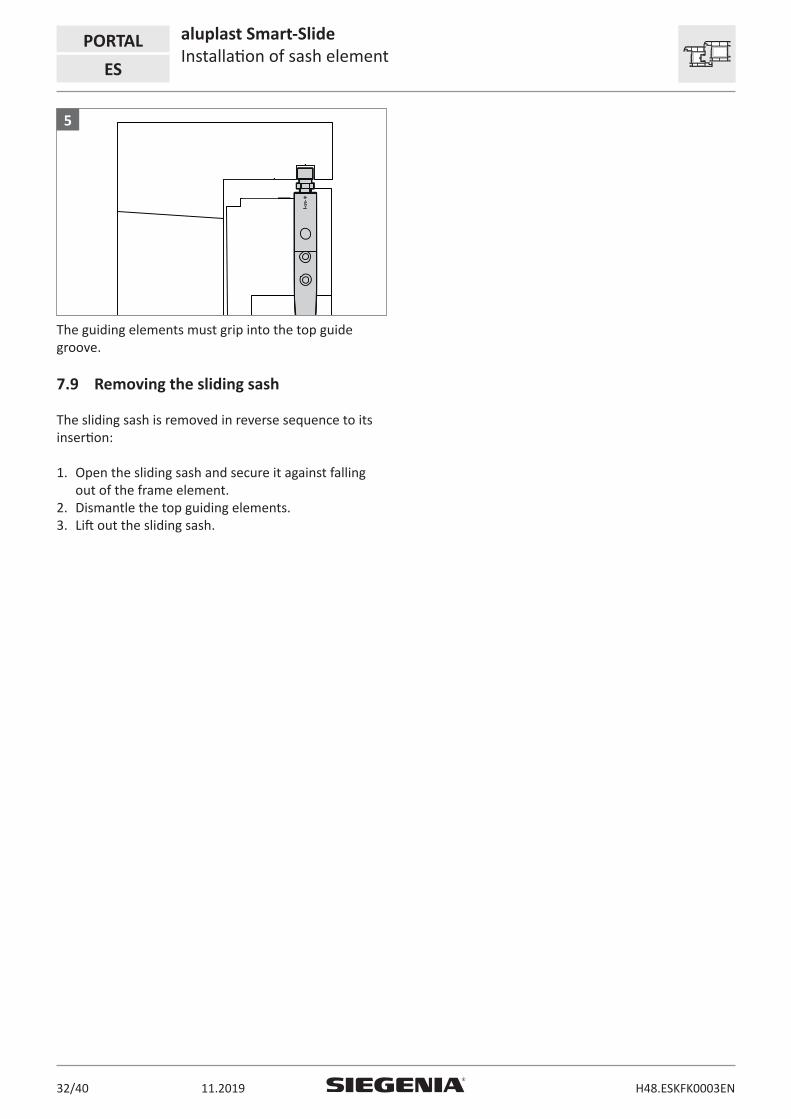
The guiding elements must grip into the top guide groove.
7.9 Removing the sliding sash
The sliding sash is removed in reverse sequence to its insertion:
1. Open the sliding sash and secure it against falling out of the frame element.
2. Dismantle the top guiding elements.3. Lift out the sliding sash.

aluplast Smart-SlideInstallation of sash element
PORTAL
ES
H48.ESKFK0003EN 11.2019 33/40
7.10 Adjustment of sliding sash
DANGER
Danger to life due to sliding sash falling out.
Due to incorrectly adjusted guiding elements
• The correct grip of the guiding elements into the guide groove must be guaranteed over the entire frame width.
max
. 6
3 mm = delivery status
The max. range must not be exceeded.
7.10.1 Adjustment of top guiding elements
+
–
11
+ 3– 2
0
The alignment must not exceed the defined adjustment range of + 3 mm/- 2 mm.
The hardware components could be subjected to strain if the maximum adjustment range is exceeded.
7.10.2 Adjustment of bottom guiding elements
+– 11
+ 3– 2
0
The alignment must not exceed the defined adjustment range of + 3 mm/- 2 mm.
The hardware components could be subjected to strain if the maximum adjustment range is exceeded.

PORTAL aluplast Smart-SlideProfile sections
ES
11.201934/40 H48.ESKFK0003EN
8 Profile sections
8.1 SI construction drawings
The dimensions of the SI construction drawings must be observed for the correct positioning of the holes and the components on the profile.
You can obtain SL construction drawings from your field sales contact person on request.

aluplast Smart-SlideDrilling and milling jigs
PORTAL
ES
H48.ESKFK0003EN 11.2019 35/40
9 Drilling and milling jigs
Material description Tooling Material number
Jig guide ES PABN4060-5000_
for adapter profile Eurogroove
for guiding elements
DrillØ 3.0Ø 4.0Ø 8.0
Jig HST/MV PABN4070-5000_
for hook striker
for vertical central lock
DrillØ 3.0
Jig AB/MV PABN4080-5000_
for stop
for horizontal central lock
DrillØ 3.0Ø 8.0

PORTAL aluplast Smart-SlideMaintenance
ES
11.201936/40 H48.ESKFK0003EN
10 Maintenance
Maintenance must be carried out on the PORTAL HShardware at least once a year. The maintenance instructions must be observed. Maintenance must be carried out twice a year if the PORTAL HS hardware is regularly exposed to extreme weather.
Use a non-acidic and non-resinous oil or care agent to lubricate the hardware components. For example:
• „KORROSIONSSCHUTZSPRAY - 300 ML“ from Würth• „ANTI-CORIT 5F SPRAY“ from Fuchs-Schmierstoffe
10.1 Cleaning and service
Use a pH-neutral detergent, diluted with warm water, to clean the PVC surfaces of the threshold, sash and frame elements. 3 ml of cleaning agent to 5 litres of water is the guideline for the dose. Most dirt can be removed with this detergent solution. Leave the cleaning agent to react for maximum 10 minutes. After cleaning, always rinse the surface with clear water.
These cleaning agents and substances damage the PVC:
• Solvent-based cleaning agents• Chlorinated cleaning agents• Acetone or acetone-based cleaning agents• Ester-based cleaning agents• Abrasive cleaning agents or scouring agents• Chemicals such as nitro-dilution• White spirit, alcohol or similar agents• Aids such as steel or scouring sponges or scouring
pads
You will find additional notes on cleaning in the information sheet „Cleaning and maintenance of PVC windows“ of the German Quality Association for PVC Window Profile Systems (Gütegemeinschaft Kunststoff-Fensterprofilsysteme e.V.):
https://www.gkfp.en/fileadmin/gkfp/inhalte_2017/Pu-blications/Cleaning_Maintenance of PVC Windows.pdf
The use of citrus-, orange- or mint extract-based cleaning agents leads to discolouration of the PVC parts!
Recommendation: hand out this cleaning information
to the end user. Have the recipient confirm that he has received the information

aluplast Smart-SlideNotes
PORTAL
ES
H48.ESKFK0003EN 11.2019 37/40
11 Notes

PORTAL aluplast Smart-SlideNotes
ES
11.201938/40 H48.ESKFK0003EN


www.siegenia.com
H48
.ESK
FK00
03EN
/00
Related Documents