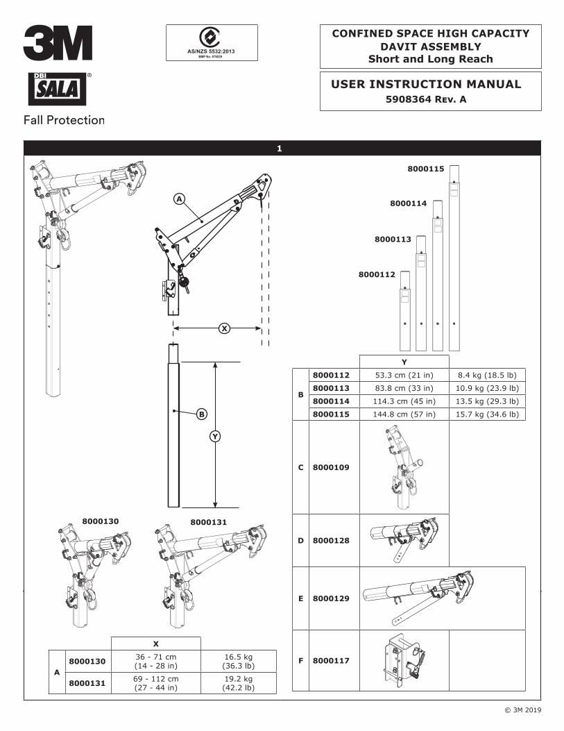
© 3M 2019 USER INSTRUCTION MANUAL 5908364 Rev. A 1 8000130 8000131 X A 8000130 36 - 71 cm (14 - 28 in) 16.5 kg (36.3 lb) 8000131 69 - 112 cm (27 - 44 in) 19.2 kg (42.2 lb) A B Y X 8000112 8000113 8000114 8000115 Y B 8000112 53.3 cm (21 in) 8.4 kg (18.5 lb) 8000113 83.8 cm (33 in) 10.9 kg (23.9 lb) 8000114 114.3 cm (45 in) 13.5 kg (29.3 lb) 8000115 144.8 cm (57 in) 15.7 kg (34.6 lb) C 8000109 D 8000128 E 8000129 F 8000117 CONFINED SPACE HIGH CAPACITY DAVIT ASSEMBLY Short and Long Reach BMP No. 678539 AS/NZS 5532:2013

Welcome message from author
This document is posted to help you gain knowledge. Please leave a comment to let me know what you think about it! Share it to your friends and learn new things together.
Transcript
© 3M 2019
User InstrUctIon ManUal5908364 Rev. A
1
8000130 8000131
X
a8000130 36 - 71 cm
(14 - 28 in)16.5 kg (36.3 lb)
8000131 69 - 112 cm(27 - 44 in)
19.2 kg(42.2 lb)
a
B
Y
X
8000112
8000113
8000114
8000115
Y
B
8000112 53.3 cm (21 in) 8.4 kg (18.5 lb)
8000113 83.8 cm (33 in) 10.9 kg (23.9 lb)
8000114 114.3 cm (45 in) 13.5 kg (29.3 lb)
8000115 144.8 cm (57 in) 15.7 kg (34.6 lb)
c 8000109
D 8000128
e 8000129
F 8000117
conFIneD sPace HIGH caPacItY DaVIt asseMBlY
short and long reachBMP No. 678539 AS/NZS 5532:2013

2
2 3 4a
C
E
F
H
A
D
G
B
F
4bC
A
B
D
E
5 6 7
A
12
34
C
12
3
B
A

3
8 9
A
B
D
C
A
B
10
A
B
≤ 38 cm (15 in)
4
11
8000130
8000131
2
1
9514444 Rev. B
9514444 Rev. B
9514445 Rev. A
9514445 Rev. A
4
7
3
8
1
2
3
4
5
6
5
9
5
6
7
7
89
10
510
8
9
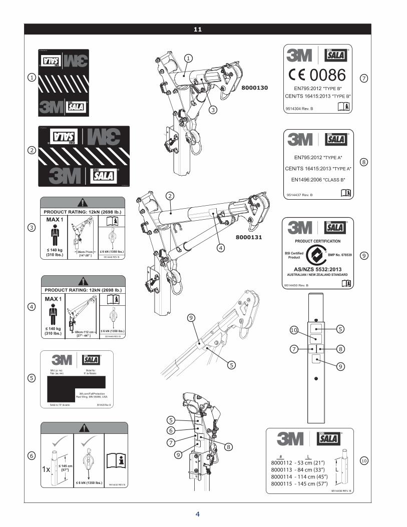
8000112 - 53 cm (21”) 8000113 - 84 cm (33”) 8000114 - 114 cm (45”) 8000115 - 145 cm (57”)
# L
9
9514304 Rev. B
0086EN795:2012 "TYPE B"
CEN/TS 16415:2013 "TYPE B"
FORM NO: 5908277 REV: A 5
SAFETY INFORMATIONPlease read, understand, and follow all safety information contained in these instructions prior to the use of this Confined Space Entry/Rescue Device. FAILURE TO DO SO COULD RESULT IN SERIOUS INJURY OR DEATH.
These instructions must be provided to the user of this equipment. Retain these instructions for future reference.
Intended Use:This Confined Space Entry/Rescue Device is intended for use as part of a complete personal fall protection or rescue system.
Use in any other application including, but not limited to, non-approved material handling applications, recreational or sports related activities, or other activities not described in the User Instructions or Installation Instructions is not approved by 3M and could result in serious injury or death.
This device is only to be used by trained users in workplace applications.
! WARNINGThis Confined Space Entry/Rescue Device is part of a personal fall protection or rescue system. It is expected that all users be fully trained in the safe installation and operation of the complete system. Misuse of this device could result in serious injury or death. For proper selection, operation, installation, maintenance, and service, refer to all Product Instructions and all manufacturer recommendations, see your supervisor, or contact 3M Technical Service.
• To reduce the risks associated with working with a Confined Space Entry/Rescue Device which, if not avoided, could result in serious injury or death:
- Inspect the device before each use, at least annually, and after any fall event. Inspect in accordance with the User Instructions. - If inspection reveals an unsafe or defective condition, remove the device from service and repair or replace according to the User
Instructions. - Any device that has been subject to fall arrest or impact force must be immediately removed from service. Refer to the User Instructions
or contact 3M Fall Protection. - The device must only be installed in the manner detailed in the Installation Instructions or User Instructions. Installations and use outside
the scope of the instruction must be approved in writing by 3M Fall Protection. - The substrate or structure to which the device is attached must be able to sustain the static loads specified for the device in the
orientations permitted in the User Instructions or Installation Instructions. - Do not exceed the number of allowable users. - Never work below a suspended load or worker. - Use caution when installing, using, and moving the device as moving parts may create potential pinch points. Refer to the User
Instructions. - Ensure proper lockout/tagout procedures have been followed as applicable. - Never attach to a system until it is positioned, fully assembled, adjusted, and installed. Do not adjust the system while a user is attached. - Only connect fall protection subsystems to the designated anchorage connection point on the device. - Prior to drilling or fastening, ensure no electric lines, gas lines, or other critical embedded systems will be contacted by the drill or the
device. - Ensure that fall protection systems/subsystems assembled from components made by different manufacturers are compatible and meet
the requirements of applicable standards, including the ANSI Z359 or other applicable fall protection codes, standards, or requirements. Always consult a Competent or Qualified Person before using these systems.
• To reduce the risks associated with working at height which, if not avoided, could result in serious injury or death: - Ensure your health and physical condition allow you to safely withstand all of the forces associated with working at height. Consult with
your doctor if you have any questions regarding your ability to use this equipment. - Never exceed allowable capacity of your fall protection equipment. - Never exceed maximum free fall distance of your fall protection equipment. - Do not use any fall protection equipment that fails pre-use or other scheduled inspections, or if you have concerns about the use or
suitability of the equipment for your application. Contact 3M Technical Services with any questions. - Some subsystem and component combinations may interfere with the operation of this equipment. Only use compatible connections.
Consult 3M prior to using this equipment in combination with components or subsystems other than those described in the User Instructions.
- Use extra precautions when working around moving machinery (e.g. top drive of oil rigs) electrical hazards, extreme temperatures, chemical hazards, explosive or toxic gases, sharp edges, or below overhead materials that could fall onto you or the fall protection equipment.
- Use Arc Flash or Hot Works devices when working in high heat environments. - Avoid surfaces and objects that can damage the user or equipment. - Ensure there is adequate fall clearance when working at height. - Never modify or alter your fall protection equipment. Only 3M or parties authorized in writing by 3M may make repairs to the equipment. - Prior to use of fall protection equipment, ensure a rescue plan is in place which allows for prompt rescue if a fall incident occurs. - If a fall incident occurs, immediately seek medical attention for the worker who has fallen. - Do not use a body belt for fall arrest applications. Use only a Full Body Harness. - Minimize swing falls by working as directly below the anchorage point as possible. - If training with this device, a secondary fall protection system must be utilized in a manner that does not expose the trainee to an
unintended fall hazard. - Always wear appropriate personal protective equipment when installing, using, or inspecting the device/system.
EN
6
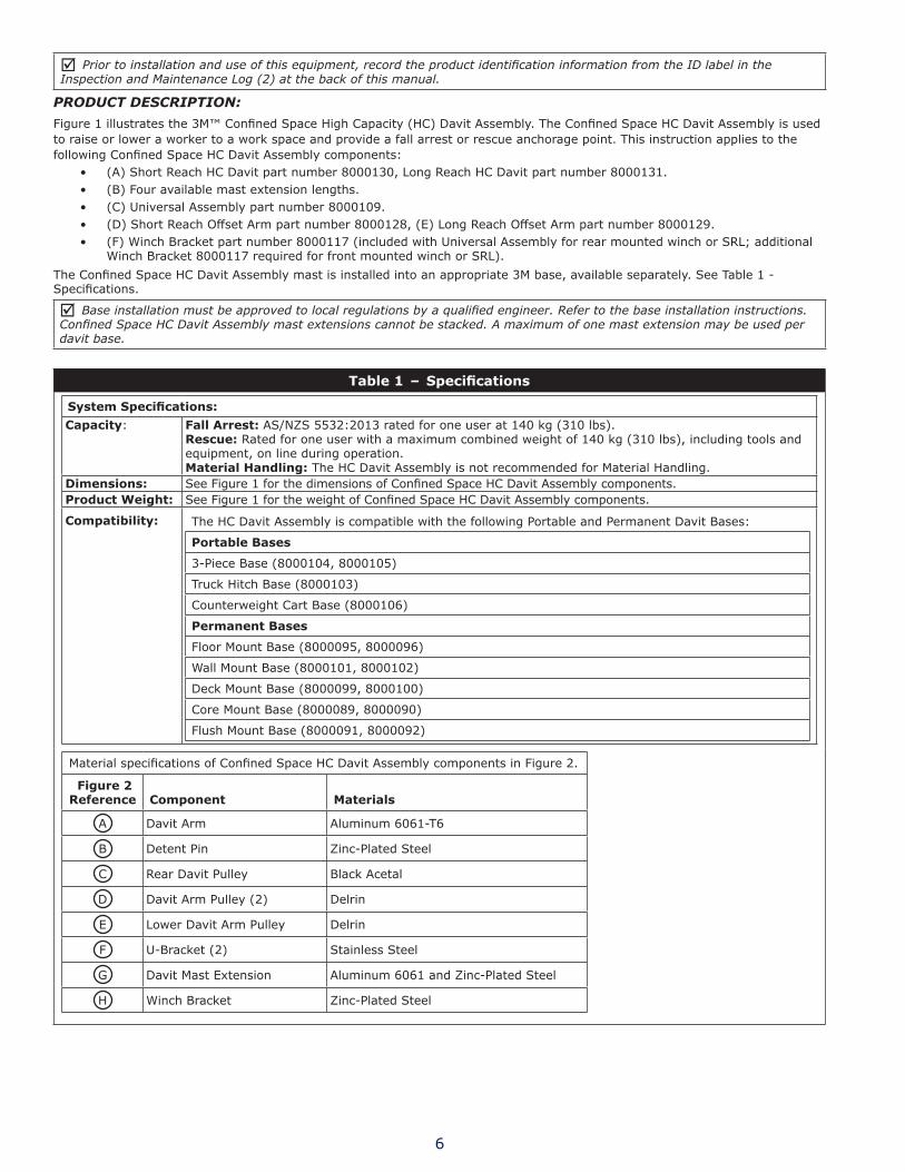
; Prior to installation and use of this equipment, record the product identification information from the ID label in the Inspection and Maintenance Log (2) at the back of this manual.
PRODUCT DESCRIPTION:
Figure 1 illustrates the 3M™ Confined Space High Capacity (HC) Davit Assembly. The Confined Space HC Davit Assembly is used to raise or lower a worker to a work space and provide a fall arrest or rescue anchorage point. This instruction applies to the following Confined Space HC Davit Assembly components:
• (A) Short Reach HC Davit part number 8000130, Long Reach HC Davit part number 8000131.• (B) Four available mast extension lengths.• (C) Universal Assembly part number 8000109.• (D) Short Reach Offset Arm part number 8000128, (E) Long Reach Offset Arm part number 8000129.• (F) Winch Bracket part number 8000117 (included with Universal Assembly for rear mounted winch or SRL; additional
Winch Bracket 8000117 required for front mounted winch or SRL).The Confined Space HC Davit Assembly mast is installed into an appropriate 3M base, available separately. See Table 1 - Specifications.
; Base installation must be approved to local regulations by a qualified engineer. Refer to the base installation instructions. Confined Space HC Davit Assembly mast extensions cannot be stacked. A maximum of one mast extension may be used per davit base.
Table 1 – Specifications
System Specifications:Capacity: Fall Arrest: AS/NZS 5532:2013 rated for one user at 140 kg (310 lbs).
Rescue: Rated for one user with a maximum combined weight of 140 kg (310 lbs), including tools and equipment, on line during operation.Material Handling: The HC Davit Assembly is not recommended for Material Handling.
Dimensions: See Figure 1 for the dimensions of Confined Space HC Davit Assembly components.Product Weight: See Figure 1 for the weight of Confined Space HC Davit Assembly components.
Compatibility: The HC Davit Assembly is compatible with the following Portable and Permanent Davit Bases:
Portable Bases
3-Piece Base (8000104, 8000105)
Truck Hitch Base (8000103)
Counterweight Cart Base (8000106)
Permanent Bases
Floor Mount Base (8000095, 8000096)
Wall Mount Base (8000101, 8000102)
Deck Mount Base (8000099, 8000100)
Core Mount Base (8000089, 8000090)
Flush Mount Base (8000091, 8000092)
Material specifications of Confined Space HC Davit Assembly components in Figure 2.
Figure 2 Reference Component Materials
A Davit Arm Aluminum 6061-T6
B Detent Pin Zinc-Plated Steel
C Rear Davit Pulley Black Acetal
D Davit Arm Pulley (2) Delrin
E Lower Davit Arm Pulley Delrin
F U-Bracket (2) Stainless Steel
G Davit Mast Extension Aluminum 6061 and Zinc-Plated Steel
H Winch Bracket Zinc-Plated Steel
7
1.0 PRODUCT APPLICATION
1.1 PURPOSE: The Confined Space HC Davit Assembly is used to raise or lower a worker to a work space and provides a fall arrest or rescue anchorage point.
1.2 STANDARDS: This Confined Space HC Davit Assembly conforms to the national or regional standard(s) identified on the front cover and Table 1 of these instructions. If this product is resold outside the original country of destination, the re-seller must provide these instructions in the language of the country in which the product will be used.
1.3 INSTALLATION & SUPERVISION: Installation of the Confined Space HC Davit Assembly must be supervised by a Competent Person1. A Qualified Person2 must verify that the structural installation meets local and federal regulations. A Qualified Person must recommend the appropriate fasteners and proper Confined Space Davit Assembly placement. Use of the Davit and attached Fall Protection equipment must be supervised by a Competent Person.
1.4 TRAINING: This equipment must be installed and used by persons trained in its correct application. This manual may be used as part of an employee training program and/or regional regulations. It is the responsibility of the users and installers of this equipment to ensure they are familiar with these instructions, trained in the correct care and use of this equipment, and are aware of the operating characteristics, application limitations, and consequences of improper use of this equipment.
1.5 RESCUE PLAN: When using the HC Davit and connected Fall Protection equipment, the employer must have a rescue plan and means at hand to implement and communicate that plan to users. A trained on-site rescue team is recommended. Team members should be provided with the equipment and techniques to perform a successful rescue. Training should be provided on a periodic basis to ensure rescue proficiency.
1.6 INSPECTION FREQUENCY: The Confined Space HC Davit Assembly shall be inspected by the User before each use and, additionally, by a Competent Person other than the user at intervals of no longer than one year.3 Inspection procedures are described in the “Inspection and Maintenance Log”. Results of each Competent Person inspection should be recorded on copies of the “Inspection and Maintenance Log”.
2.0 SYSTEM REQUIREMENTS
2.1 COMPONENT COMPATIBILITY: 3M equipment is designed for use with other 3M approved components and subsystems only. Substitutions or replacements made with non-approved components or subsystems may jeopardize compatibility of equipment and may affect the safety and reliability of the complete system.
2.2 PERSONAL FALL ARREST SYSTEM: Personal Fall Arrest Systems (PFAS) used with the system must meet applicable Fall Protection standards, codes, and requirements. The PFAS must incorporate a Full Body Harness, and limit Arresting Force to the following values:
Maximum Arresting Force Free FallPFAS with Shock Absorbing Lanyard 6 kN (1,350 lbs) Refer to the instruction(s) included with your
Lanyard or SRD for Free Fall limitations.PFAS with Self Retracting Device (SRD) 6 kN (1,350 lbs)
1 Competent Person: One who is capable of identifying existing and predictable hazards in the surroundings or working conditions which are unsanitary, hazard-ous, or dangerous to employees, and who has authorization to take prompt corrective measures to eliminate them.
2 Qualified Person: An individual with a recognized degree or professional certificate, and extensive experience in Fall Protection. This individual must be capable of design, analysis, evaluation, and specification of Fall Protection.
3 Inspection Frequency: Extreme working conditions (harsh environments, prolonged use, etc.) may require increasing the frequency of competent person inspections.

8
3.0 INSTALLATION3.1 PLANNING: Plan your fall protection system prior to use and installation of the Confined Space HC Davit Assembly.
Account for all factors that may affect your safety before, during and after a fall.
; Plan your work program before starting. Have the required people, equipment and procedures available to do the job.
; Always work in teams. One person being raised or lowered and another person to pay out and reel in the line.
; Wear appropriate protective gear such as a hard hat, safety glasses, protective shoes with slip resistant soles, heavy gloves, protective clothing and a face mask.
; Confined Space HC Davit Assembly mast extensions cannot be stacked. A maximum of one mast extension may be used per davit base.
; All winch and SRL mounting parts and hardware must be supplied or approved by 3M Fall Protection.
; Securely anchor the winch before using.
; System users must use an approved full body harness.
; Use only retractable devices or energy absorbers with a maximum arrest force equal to or lower than the lowest rated component of your system.
; Retractable devices or energy absorbers must be installed and used in accordance with the manufacturer’s instructions.
; Modular components are labeled with the capacities and rating to which they were designed, tested, and manufactured. The rating of any system is considered to be the rating of the lowest rated component in the system. Do not use equipment if rating labels are damaged or illegible. New labels are available from 3M Fall Protection.
; The Confined Space HC Davit Assembly should be removed from the job site when no longer needed.
3.2 INSTALL THE CoNfINEd SPACE HC dAvIT ASSEmbLy:
1. (Figure 3) Insert the Confined Space HC Davit Assembly Mast Extension into an installed 3M HC davit base. (See Table 1 for 3M Base descriptions.) Follow davit base installation instructions for securing the davit base to the anchorage structure.
2. Attach the Davit Head assembly to the Universal assembly:
a. (Figure 4a) Insert the davit head gusset tube (A) into the universal assembly gusset weldment (B). Use detent pin (C) to secure the gusset tube in the gusset weldment.
b. (Figure 4b) Use the hitch pin (D) to attach the davit head arm tube between the side plates (E) of the universal assembly. Secure the hitch pin with the lynch pin that is connected to the opposite side of the universal assembly.
3. (Figure 5) Place the assembled davit arm/universal on the mast extension. The bottom edge of the davit arm tube must contact the ridge of the mast extension. Center the notch at the bottom of the davit arm tube on the screw located on the ridge of the mast extension.
4. (Figure 6) The davit arm extension length can be adjusted to one of four positions. Remove detent pin (A) and slide the davit arm extension out or in to reach the desired length. The davit arm must be secured at that extension position with the detent pin (A). Fully insert the detent pin.
5. (Figure 7) The davit arm angle can be adjusted to one of three positions. Remove detent pin (C) and slide the gusset tube (A) in or out of the gusset weldment (B). The gusset tube must be secured with the detent pin (C). Fully insert the detent pin.
6. (Figure 8) Install the winch according to the manufacturer’s instructions. The winch is mounted with the winch bracket that is included with the universal assembly. The winch cable is typically routed over the rear pulley (A) on the universal assembly and the top front pulley (B) on the davit arm. An alternate and/or additional front mounted configuration is possible. See Section 3.3.
3.3 WINCH bRACKET 8000117:
1. (Figure 9) A front mounted winch or SRL can be added to the Confined Space HC Davit Assembly mast extension by installing a second winch bracket 8000117 (purchased separately). Secure the winch bracket (A) to the mast extension with the two winch bracket detent pins (B). The winch or SRL cable uses the front pulley (C) on the universal assembly and the bottom front pulley (D) on the davit arm.
3.4 U-bRACKET ATTACHmENT PoINTS:
(Figure 10) The two U-Bracket attachment points (A and B) can be used for fall arrest or rescue. When using U-Bracket attachment point A, do not exceed horizontal distance of 38 cm (15 in) from the davit base.
4.0 USE
4.1 bEfoRE EACH USE: Verify that your work area and Personal Fall Arrest System (PFAS) meet all criteria defined in Section 2 and a formal rescue plan is in place. Inspect the Confined Space HC Davit Assembly per the ‘User’ inspection points defined on the “Inspection and Maintenance Log” in this manual. If inspection reveals an unsafe or defective condition, do not use the system. Remove the system from service and destroy, or contact 3M regarding replacement or repair.
5.0 INSPECTION
5.1 INSPECTIoN fREQUENCy: The Confined Space HC Davit Assembly must be inspected at the intervals defined in Section 1. Inspection procedures are described in the ‘Inspection and Maintenance Log’ 2 Inspect all other components of the Fall Protection System per the frequencies and procedures defined in the manufacturer’s instructions.
5.2 dEfECTS: If inspection reveals an unsafe or defective condition, remove the Confined Space HC Davit Assembly from service immediately and contact 3M regarding replacement or repair. Do not attempt to repair the Fall Arrest System.

9
; Authorized Repairs Only: Only 3M or parties authorized in writing may make repairs to this equipment.
5.3 PRodUCT LIfE: The functional life of the Confined Space HC Davit Assembly is determined by work conditions and maintenance. As long as the product passes inspection criteria, it may remain in service.
6.0 MAINTENANCE, SERVICING, STORAGE
6.1 CLEANING: Periodically clean the Confined Space HC Davit Assembly’s metal components with a soft brush, warm water, and a mild soap solution. Ensure parts are thoroughly rinsed with clean water.
6.2 SERvICE: Only 3M or parties authorized in writing by 3M may make repairs to this equipment. If the Confined Space HC Davit Assembly has been subject to fall force or inspection reveals an unsafe or defective conditions, remove the system from service and contact 3M regarding replacement or repair.
6.3 SToRAGE ANd TRANSPoRT: When not in use, store and transport the Confined Space HC Davit Assembly and associated fall protection equipment in a cool, dry, clean environment out of direct sunlight. Avoid areas where chemical vapors may exist. Thoroughly inspect components after extended storage.
7.0 LABELS
Figure 11 illustrates labels on the Confined Space HC Davit Assembly. Labels must be replaced if they are not fully legible.

Table 2 – Inspection and Maintenance LogInspection Date: Inspected By:
Components: Inspection: (See Section 5 for Inspection Frequency) UserCompetent
Person1
Confined Space HC Davit Assembly (Figures 1 and 2)
Inspect the Confined Space HC Davit Assembly for cracks, dents, or deformities.
Inspect the entire unit for corrosion.
Inspect all fasteners to ensure they are tight. Tighten if necessary.
Inspect to ensure that all pins are fully inserted and hitch pins are securely attached with lynch pins.
Labels (Figure 11) Verify that all labels are securely attached and are legible (see ‘Labels’)
PFAS and Other Equipment
Additional Personal Fall Arrest System (PFAS) equipment (harness, SRL, etc.) that are used with the HC Davit should be installed and inspected per the manufacturer’s instructions.
Serial Number(s): Date Purchased:Model Number: Date of First Use:
Corrective Action/Maintenance: Approved By:Date:
Corrective Action/Maintenance: Approved By:Date:
Corrective Action/Maintenance: Approved By:Date:
Corrective Action/Maintenance: Approved By:Date:
Corrective Action/Maintenance: Approved By:Date:
Corrective Action/Maintenance: Approved By:Date:
Corrective Action/Maintenance: Approved By:Date:
Corrective Action/Maintenance: Approved By:Date:
Corrective Action/Maintenance: Approved By:Date:
Corrective Action/Maintenance: Approved By:Date:
Corrective Action/Maintenance: Approved By:Date:
Corrective Action/Maintenance: Approved By:Date:
Corrective Action/Maintenance: Approved By:Date:
Corrective Action/Maintenance: Approved By:Date:
Corrective Action/Maintenance: Approved By:Date:
Corrective Action/Maintenance: Approved By:Date:
1 Competent Person: One who is capable of identifying existing and predictable hazards in the surroundings or working conditions which are unsanitary, hazardous, or dangerous to employees, and who has authorization to take prompt corrective measures to eliminate them.


USA3833 SALA Way Red Wing, MN 55066-5005 Toll Free: 800.328.6146Phone: 651.388.8282Fax: [email protected]
BrazilRua Anne Frank, 2621Boqueirão Curitiba PR81650-020BrazilPhone: [email protected]
MexicoCalle Norte 35, 895-ECol. Industrial VallejoC.P. 02300 AzcapotzalcoMexico D.F.Phone: (55) [email protected]
ColombiaCompañía Latinoamericana de Seguridad S.A.S.Carrera 106 #15-25 Interior 105 Manzana 15Zona Franca - Bogotá, ColombiaPhone: 57 1 [email protected]
Canada260 Export Boulevard Mississauga, ON L5S 1Y9 Phone: 905.795.9333 Toll-Free: 800.387.7484 Fax: 888.387.7484 [email protected]
EMEA (Europe, Middle East, Africa)EMEA Headquarters:Le Broc CenterZ.I. 1re Avenue - BP1506511 Carros Le Broc CedexFrancePhone: + 33 04 97 10 00 10Fax: + 33 04 93 08 79 [email protected]
Australia & New Zealand95 Derby StreetSilverwaterSydney NSW 2128AustraliaPhone: +(61) 2 8753 7600Toll-Free : 1800 245 002 (AUS)Toll-Free : 0800 212 505 (NZ) Fax: +(61) 2 8753 7603 [email protected]
AsiaSingapore:1 Yishun Avenue 7Singapore 768923Phone: +65-6450 8888Fax: +65-6552 [email protected]
Shanghai:19/F, L’Avenue, No.99 Xian Xia RdShanghai 200051, P R China Phone: +86 21 62539050Fax: +86 21 [email protected]
Korea:3M Koread Ltd20F, 82, Uisadang-daero,Yeongdeungpo-gu, SeoulPhone: +82-80-033-4114Fax: [email protected]
Japan:3M Japan Ltd6-7-29, Kitashinagawa, Shinagawa-ku, TokyoPhone: +81-570-011-321Fax: [email protected]
WEBSITE:3M.com/FallProtection
I S O9 0 0 1 FM534873
EU DECLARATION OF CONFORMITY:3M.com/FallProtection/DOC
GLOBAL PRODUCT WARRANTY, LIMITED REMEDY AND LIMITATION OF LIABILITY
WARRANTY: THE FOLLOWING IS MADE IN LIEU OF ALL WARRANTIES OR CONDITIONS, EXPRESS OR IMPLIED, INCLUDING THE IMPLIED WARRANTIES OR CONDITIONS OF MERCHANTABILITY OR FITNESS FOR A PARTICULAR PURPOSE.Unless otherwise provided by local laws, 3M fall protection products are warranted against factory defects in workmanship and materials for a period of one year from the date of installation or first use by the original owner.LIMITED REMEDY: Upon written notice to 3M, 3M will repair or replace any product determined by 3M to have a factory defect in workmanship or materials. 3M reserves the right to require product be returned to its facility for evaluation of warranty claims. This warranty does not cover product damage due to wear, abuse, misuse, damage in transit, failure to maintain the product or other damage beyond 3M’s control. 3M will be the sole judge of product condition and warranty options. This warranty applies only to the original purchaser and is the only warranty applicable to 3M’s fall protection products. Please contact 3M’s customer service department in your region for assistance.LIMITATION OF LIABILITY: TO THE EXTENT PERMITTED BY LOCAL LAWS, 3M IS NOT LIABLE FOR ANY INDIRECT, INCIDENTAL, SPECIAL OR CONSEQUENTIAL DAMAGES INCLUDING, BUT NOT LIMITED TO LOSS OF PROFITS, IN ANY WAY RELATED TO THE PRODUCTS REGARDLESS OF THE LEGAL THEORY ASSERTED.
Related Documents