e,*,- i ASME B1 8.6.2-1 N88 [Revision 01 ANS I B1 8.6.2-1 972 (R1 993)] C , " SLOTTED HEAD CAP SCREWS, SQUARE HEAD SET SCREWS, SET SGREWS (INCH SERIES) d AND SLOTTED HEADlESS AN AMERICAN NATIONAL STANDARD The American Society of Mechanical Engineers COPYRIGHT American Society of Mechanical Engineers Licensed by Information Handling Services COPYRIGHT American Society of Mechanical Engineers Licensed by Information Handling Services

ASME B 18.6.2 (1998)
Oct 28, 2015
Welcome message from author
This document is posted to help you gain knowledge. Please leave a comment to let me know what you think about it! Share it to your friends and learn new things together.
Transcript

e,*,- i
ASME B1 8.6.2-1 N88 [Revision 01 ANSI B1 8.6.2-1 972 (R1 993)]
C,"
SLOTTED HEAD CAP SCREWS, SQUARE HEAD SET SCREWS,
SET SGREWS (INCH SERIES) d AND SLOTTED HEADlESS
A N A M E R I C A N N A T I O N A L S T A N D A R D
The American Society of Mechanical Engineers
COPYRIGHT American Society of Mechanical EngineersLicensed by Information Handling ServicesCOPYRIGHT American Society of Mechanical EngineersLicensed by Information Handling Services

The American Society of Mechanical Engineers
A N A M E R I C A N N A T I O N A L S T A N D A R D
SLOTTED HEAD EAP SEREWS, SQUARE HEAD SET SCREWS
AND SLOTTED HEADlESS SET SCREWS (INCH SERIES)
ASME B1 8.6.2-1 998 [Revision 01 ANSI B1 8.6.2-1 972 (R1 993)]
COPYRIGHT American Society of Mechanical EngineersLicensed by Information Handling ServicesCOPYRIGHT American Society of Mechanical EngineersLicensed by Information Handling Services

STD-ASME BZB.b.2-ENGL L998 m 0757b70 Ob08545 471
Date of Issuance: April 30, 1999
This Standard will be revised when the Society approves the issuance of a new edition. There will be no addenda issued to this edition.
ASME is the registered trademark of The American Society of Mechanical Engineers.
This code or standard was developed under procedures accredited as meeting the criteria for American National Standards. The Standards Committee that approved the code or standard was balanced to assure that individuals from competent and concerned interests have had an opportunity to participate. The proposed code or standard was made available for public review and comment, which provides an opportunityfor additional public input from industry, academia, regulatory agencies, and the public-at-large.
ASME does not "approve," "rate," or "endorse" any item, construction, proprietary device, or activity.
ASME does not take any position with respect to the validity of any patent rights asserted in connection with any items mentioned in this document, and does not undertake to insure anyone utilizing a standard against liability for infringement of any applicable Letters Patent, nor assume any such liability. Users of a code or standard are expressly advised that determination of the validity of any such patent rights, and the risk of infringement of such rights, is entirely their own responsibility.
Participation by federal agency representative(s) or person(s) affiliated with industry is not to be interpreted as government or industry endorsement of this code or standard.
ASME accepts responsibilityfor onlythose interpretations issued in accordance with governing ASME procedures and policies which preclude the issuance of interpretations by individual volunteers.
No part of this document may be reproduced in any form, in an electronic retrieval system or otherwise,
without the prior written permission of the publisher.
The American Society of Mechanical Engineers Three Park Avenue, New York, NY 10016-5990
Copyright O 1999 by THE AMERICAN SOCIETY OF MECHANICAL ENGINEERS
All Rights Reserved Printed in U.S.A.
COPYRIGHT American Society of Mechanical EngineersLicensed by Information Handling ServicesCOPYRIGHT American Society of Mechanical EngineersLicensed by Information Handling Services

STD*ASME BLB*b.Z-ENGL L778 I 0757b70 Ob0854b 308 I
FOREWORD
(This Foreword is not part of ASME B18.6.2-1998.)
American National Standards Committee B18 for the standardization of bolts, screws, nuts, rivets, and similar fasteners was organized in March 1922, as Sectional Committee B 18 under the American Engineering Standards Committee', with the Society of Automotive Engineers and the American Society of Mechanical Engineers as joint sponsors. Subcommittee 3* was subsequently established and charged with the responsibility for technical content of standards covering slotted and recessed head screws.
Over the years following the issuance of this document, the need for standards more comprehensive than head configurations became apparent. At a meeting held on April 14, 1942, Subcommittee 32 was reorganized and enlarged, and the following operating scope was established.
The scope of Subcommittee 32 shall consist of the development and promulgation of American Standards embracing screw products variously known as machine screws, wood screws, tapping screws, slotted head cap screws, slotted headless set screws, and machine screw nuts. The standards shall comprise complete product standards covering all dimensions and tolerances required for the specification and production of the products. Details shall include such boundary dimensions as nut width and thickness; screw head dimensions; slot and recess dimensions; body dimensions; thread classification or thread detail, as required; thread length; point design; chamfers; underhead fillets; and supporting general specifications covering the quality, finish, and the acceptable tolerances and limits as well as any information that may be necessary to ensure satisfactory application of the products. This Standard was developed and declared an American Standard, ASA B18.6, on April 12, 1947.
At the April 1954 meeting, Subcommittee 32, contemplating a partial revision of the ASA B18.6 document, recommended the publication of standards for wood screws, cap and set screws, machine screws, and tapping and drive screws in four separate documents, each of which would consist of a complete product specification. This approach was confirmed by the B18 Committee with the further stipulation that the coverage for hexagon head cap screws, square head set screws, and machine screw nuts from the ASA B18.2 standard be transferred to the documents covering cap and set screws and machine screws, respectively. It was understood that jurisdiction over the square head set screws and hexagon head cap screws would remain with Subcommittee 2 and that Subcommittee 32 would retain responsibility for machine screw nuts. Following this confirmation and additional direction, proposals for the new documents were prepared.
The proposed standard combining the coverage for hexagon head cap screws and square head set screws from ASA B18.2-1952 with updated specifications for slotted head cap screws and slotted headless screws from BlX.6-1947 was developed and found acceptable by both subcommittees. After approval by letter ballot of the B18 Committee and the sponsor organizations, the proposal was submitted to the American Standards Association
' As of October 9, 1969, the American Engineering Standards Committee was redesignated the American National
* As of April I , 1996, Subcommittee 3 was redesignated subcommittee 6. Standards Institute, Inc.
111 ...
COPYRIGHT American Society of Mechanical EngineersLicensed by Information Handling ServicesCOPYRIGHT American Society of Mechanical EngineersLicensed by Information Handling Services

STD-ASME B L B - b - Z - E N G L 1978 0759b70 Ob085Y7 2 4 4
for recognition. It was formally designated an American Standard, ASA B18.6.2, in June 1956, superseding in part the parent documents.
The document was revised further in 1961. After several years of development, and following approval by letter ballot of the B 18 Standards Committee and sponsor organizations, this proposal was submitted to the American National Standards Institute for designation as an American National Standard. This was granted on January 28, 1972.
In 1990 Subcommittee 6 initiated work to revise para. 3.6.1 for square head set screws. Several drafts that were prepared resulted in further refinements for dimensional conformance, designation, and material for all products. These changes were balloted and approved by the ASME B18 Committee. The proposal was submitted to the American National Standards Institute and designated an American National Standard on August 6, 1998.
iv
COPYRIGHT American Society of Mechanical EngineersLicensed by Information Handling ServicesCOPYRIGHT American Society of Mechanical EngineersLicensed by Information Handling Services

ASME B18 STANDARDS COMMITTEE Standardization of Bolts, Nuts, Rivets, Screws,
Washers, and Similar Fasteners
(The following is the roster of the Committee at the time of approval of this Standard.)
OFFICERS
D. A. Clever, Chair R. D. Strong, Vice Chair S. W. Vass, Vice Chair R. L. Crane, Secretary
COMMllTEE PERSONNEL
J. C. Akins, Safety Socket Screw Corp. J. Altman, Rotor Clip Co. J. H. Slass, Alternate, Rotor Clip Co. J. B. Belford, Lawson Products, Inc. J. A. Buda, SPS Technologies D. A. Clever, Deere and Co. A. P. Cockman, Ford Motor Co. T. Collier, Cam-Tech Industries, Inc. R. L. Crane, The American Society of Mechanical Engineers A. C. DiCola, Wrought Washer Manufacturing, Inc. A. Dinh, Defense Industrial Supply Center W. D. Downing, Consultant B. A. Dusina, Federal Screw Works D. S. George, Ford Motor Co. B. Hasiuk, Defense Industrial Supply Center A. C. Hood, ACH Technologies J. Hubbard, Rockford Fastener, Inc. F. W. Kern, The Society of Automotive Engineers W. H. Kopke, ITW Shakeproof Industrial Products J. G. Langenstein, Consultant M. Levinson, ITW Shakeproof Industrial Products L. L. Lord, Caterpillar, Inc. A. D. McCrindle, Genfast Manufacturing Co. K. E. McCullough, Consultant R. F. Novotny, Textron M. D. Prasad, General Motors Corp. W. Schevey, BGM Fastener Co., Inc. R. D. Strong, General Motors Corp. J. F. Sullivan, National Fasteners Distribution Association R. L. Tennis, Caterpillar, Inc. S. W. Vass, Industrial Fasteners Institute R. G. Weber, Fairfield University C. J. Wilson, Industrial Fasteners Institute
V
COPYRIGHT American Society of Mechanical EngineersLicensed by Information Handling ServicesCOPYRIGHT American Society of Mechanical EngineersLicensed by Information Handling Services
SUBCOMMllTEE 6 - SLOlTED AND RECESSED HEAD SCREWS
R. D. Strong, Chair, General Motors Corp. D. Broomfield, Illinois Tool Works, Inc. D. A. Clever, Deere and Co. A. Dinh, Defense Industrial Supply Center J. Greenslade, Greenslade and Co. A. Herskovitz, U.S. Army ARDEC M. W. Holubecki, Electric Boat Corp. J. Hubbard, Rockford Fastener, Inc. R. W. Kerr, Kerr Lakeside, Inc. R. F. Novotny, Textron J. A. Schlink, Caterpillar, Inc. J. F. Sullivan, National Fasteners Distribution Association C. B. Wackrow, MNP Corp. C. J. Wilson, Industrial Fasteners Institute
vi
COPYRIGHT American Society of Mechanical EngineersLicensed by Information Handling ServicesCOPYRIGHT American Society of Mechanical EngineersLicensed by Information Handling Services
CORRESPONDENCE WITH THE B18 COMMITTEE
General. ASME Standards are developed and maintained with the intent to represent the consensus of concerned interests. As such, users of this Standard may interact with the Committee by requesting interpretations, proposing revisions, and attending Committee meetings. Correspondence should be addressed to:
Secretary, B18 Main Committee The American Society of Mechanical Engineers Three Park Avenue New York, NY 10016-5990
Proposing Revisions. Revisions are made periodically to the Standard to incorporate changes that appear necessary or desirable, as demonstrated by the experience gained from the application of the Standard. Approved revisions will be published periodically.
The Committee welcomes proposals for revisions to this Standard. Such proposals should be as specific as possible, citing the paragraph number(s), the proposed wording, and a detailed description of the reasons for the proposal, including any pertinent documentation.
Interpretations. Upon request, the B 18 Committee will render an interpretation of any requirement of the Standard. Interpretations can only be rendered in response to a written request sent to the Secretary of the B 18 Main Committee.
The request for interpretation should be clear and unambiguous. It is further recommended that the inquirer submit hisher request in the following format:
Subject: Cite the applicable paragraph number(s) and the topic of the inquiry. Edition: Cite the applicable edition of the Standard for which the interpretation
is being requested. Question: Phrase the question as a request for an interpretation of a specific
requirement suitable for general understanding and use, not as a request for an approval of a proprietary design or situation. The inquirer may also include any pians or drawings, which are necessary to explain the question; however, they should not contain proprietary names or information.
Requests that are not in this format may be rewritten in the appropriate format by the Committee prior to being answered, which may inadvertently change the intent of the original request.
ASME procedures provide for reconsideration of any interpretation when or if additional information that might affect an interpretation is available. Further, persons aggrieved by an interpretation may appeal to the cognizant ASME Committee or Subcommittee. ASME does not “approve,” “certify,” “rate,” or “endorse” any item, construction, proprietary device, or activity.
Attending Committee Meetings. The B 18 Main Committee regularly holds meetings, which are open to the public. Persons wishing to attend any meeting should contact the Secretary of the B18 Main Committee.
vii
COPYRIGHT American Society of Mechanical EngineersLicensed by Information Handling ServicesCOPYRIGHT American Society of Mechanical EngineersLicensed by Information Handling Services
STD-ASME BL8-b.Z-ENGL 1778 m 0757b7f l Ob08551 775
CONTENTS
... Foreword ............................................................................ 111
Standards Committee Roster ........................................................... v Committee Correspondence ............................................................ vii
1 Introductory Notes . . . . . . . . . . . . . . . . . . . . . . . . . . . . . . . . . . . . . . . . . . . . . . . . . . . . . . . . . . . . 1
2 General Data for Slotted Head Cap Screws ................................... 2
3 General Data for Square Head Set Screws ................................... 11
4 General Data for Slotted Headless Set Screws ............................... 13
Tables I Dimensions of Slotted Flat Countersunk Head Cap Screws ........................ 3 2 Dimensions of Slotted Round Head Cap Screws .................................. 4
4 Dimensions of Square Head Set Screws .......................................... 6 5 Dimensions of Slotted Headless Set Screws ....................................... 8 6 Length Tolerances: Slotted Head Cap Screws ..................................... 10 7 Length Tolerances: Square Head Set Screws ...................................... 12
3 Dimensions of Slotted Fillister Head Cap Screws ................................. 5
8 Length Tolerances: Slotted Headless Set Screws ........................... i . . . . . . . 13
Mandatory Appendices I Thread Runout Sleeve Gages for Slotted Head Cap Screws ........................ 17 II Protrusion Gaging of Flat Countersunk Head Cap Screws .......................... 19
Nonmandatory Appendices A Formulas for Dimensions ........................................................ 21 B Wrench Openings for Square Head Set Screws .................................... 25
COPYRIGHT American Society of Mechanical EngineersLicensed by Information Handling ServicesCOPYRIGHT American Society of Mechanical EngineersLicensed by Information Handling Services

S T D - A S M E BLd.b.2-ENGL L778 bl 0757b70 Ob08552 b O L I
ASME 818.6.2-1998
SLOTTED HEAD CAP SCREWS, SQUARE HEAD SET SCREWS, AND SLOTTED HEADLESS SET SCREWS (INCH SERIES)
1 INTRODUCTORY NOTES bear against a mating part at the opposite end. The head has a rounded top surface and four flat sides with
1.1 Scope an underhead construction that may be flat, conical, or rounded into a relief in the screw shank. Dimensions
1.1.1 This Standard covers the complete general and are in Table 4. dimensional data for the various styles of slotted head cap screws and square head and slotted headless set screws recognized as “American National Standard.” Also included are appendices covering thread runout sleeve gages for cap screws, protrusion gaging of flat countersunk head cap screws, formulas on which dimensional data are based, and wrench openings for square head set screws. It should be understood, how- ever, that where questions arise concerning acceptance of a product, the dimensions in the tables shall supersede those recalculated by formula.
1 .I .2 The inclusion of dimensional data in this Standard is not intended to imply that all of the products described are stock production sizes. Consumers should consult with suppliers concerning the availability of products.
1.2 Slotted Head Cap Screws
1.4 Slotted Headless Set Screws
The slotted headless set screw has threads extending over the entire length with a point designed to bear against a mating part at one end and a slot for driving at the opposite end. Dimensions are given in Table 5.
1.5 Referenced Standards
Unless otherwise specified, the referenced standard shall be the most recent issue.
ASME B 1.1, Unified Inch Screw Threads (UN and UNR Thread Form)
ASME B1.3M, Screw Thread Gaging Systems for Dimensional Acceptability - Inch and Metric Screw Threads (UN, UNR, UNJ, M, and MJ)
ANSI B 18.12, Glossary of Terms for Mechanical Fas- teners
The head styles covered by this Standard are enumer- ASME B18.18.1M, Inspection and Quality Assurance
ASME B 18.18.2M, Inspection and Quality Assurance
ersunk head has a flat top surface and a Conical bearing ASME ~ 1 8 . 2 4 ~ 1 , part Identifying Number (PIN) Code surface with a head angle of 80-82 deg. Dimensions System Standard for B 18 Externally Threaded are given in Table 1. Products
ated and described as follows: for General Purpose Fasteners
1.2.1 Flat Countersunk Head. The flat count- for High Volume Machine Assembly Fasteners
1.2.2 Round Head. The round head has a semi- ASME Y 14.5M, Dimensioning and Tolerancing
elliptical top surface and a flat bearing surface. Dimen- Publisher: The American Society of Mechanical Engi- sions are given in Table 2. neers, Three Park Avenue, New York, New York,
10016-5990; Order Department: 22 Law Drive, Box 1.2.3 Fillister Head. The fillister head has a 2300, Fairfield, NJ 07007-2300
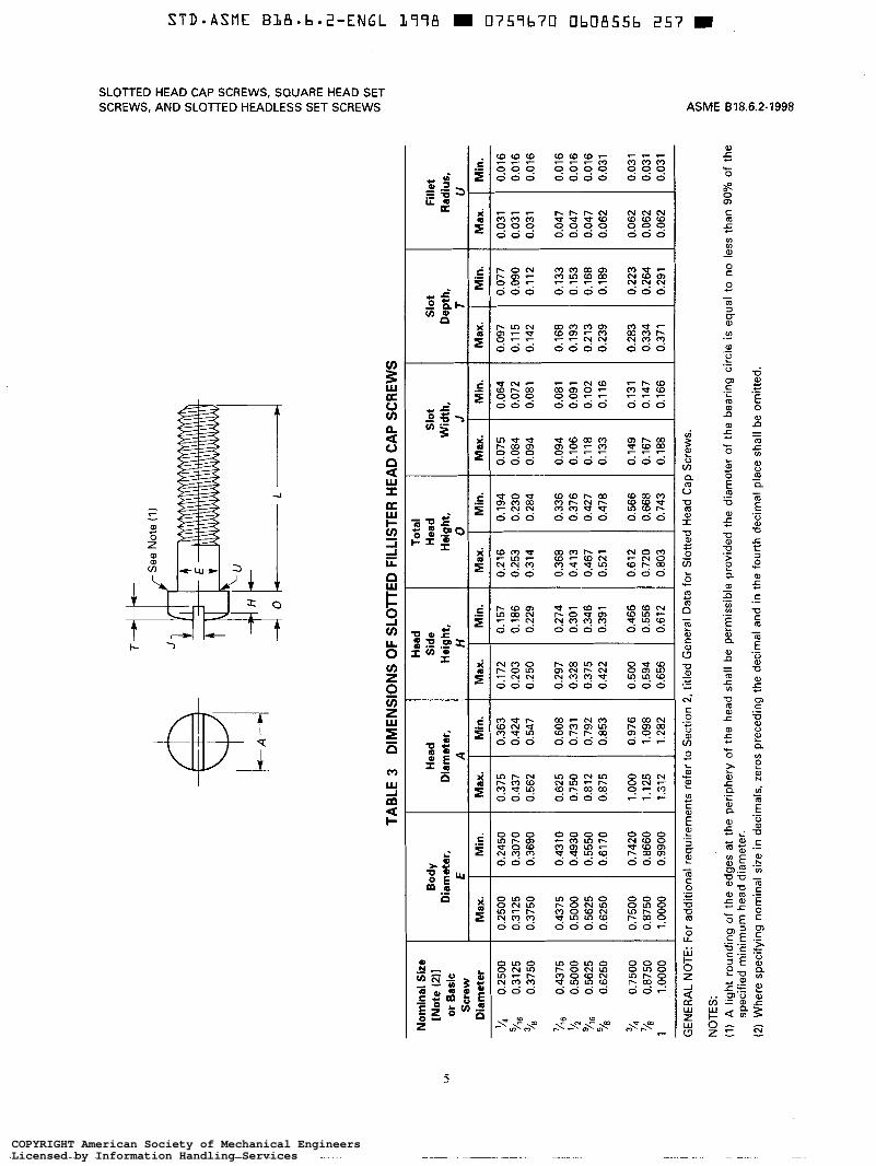
rounded top surface, cylindrical sides, and a flat bearing surface. Dimensions are given in Table 3. ASTM A 307, Carbon Steel Bolts and Studs, 60000
psi Tensile Strength
1.3 Square Head Set Screws ASTM A 354, Quenched and Tempered Alloy Steel
Bolts, Studs, and Other Externally Threaded Fasteners The square head set screw has threads extending ASTM A 380, Cleaning, Descaling, and Passivation of
‘ close to the head at one end and a point designed to Stainless Steel Parts, Equipment, and Systems
1
COPYRIGHT American Society of Mechanical EngineersLicensed by Information Handling ServicesCOPYRIGHT American Society of Mechanical EngineersLicensed by Information Handling Services

STD*ASME B L 8 - b - 2 - E N G L 1778 I 0759b70 Ob08553 5 4 8 E
ASME B18.6.2-1998
ASTM A 449, Quenched and Tempered Steel Bolts
ASTM B 633, Electrodeposited Coatings of Zinc on
ASTM F 468, Nonferrous Bolts, Hex Cap Screws, and
ASTM F 593, Stainless Steel Bolts, Hex Cap Screws,
ASTM F 788/F 788M, Surface Discontinuities of Bolts,
and Studs
Iron and Steel
Studs for General Use
and Studs
Screws, and Studs, Inch and Metric Series
Publisher: The American Society for Testing and Materi- als, 100 Barr Harbor Drive, West Conshohocken, PA 19428-2959
SAE J429, Mechanical and Material Requirements of Externally Threaded Fasteners
Publisher: The Society of Automotive Engineers, 400 Commonwealth Drive, Warrendale, PA 15096-0001.
1.6 Terminology
For definitions of terms relating to fasteners or compo- nent features thereof used in this Standard, refer to ANSI B18.12.
1.7 Dimensions
All dimensions in this Standard are given in inches,
Symbols and terms specifying geometric characteris- unless otherwise stated.
tics are defined in ASME Y14.5M.
1.8 Options
Options, where specified, shall be at the discretion of the manufacturer unless otherwise agreed upon by the manufacturer and the purchaser.
2 GENERAL DATA FOR SLOlTED HEAD CAP SCREWS
2.1 Heads
2.1.1 Head Height. All dimensions pertaining to head height specified in the dimensional tables shall be measured parallel to the axis of the screw, and
SLOTTED HEAD CAP SCREWS, SQUARE HEAD SET SCREWS, AND SLOTTED HEADLESS SET SCREWS
those relating to the top of the head shall represent a metal-to-metal measurement. In other words, any truncation of rounded head contours due to the slot shall not be considered part of the head height.
Total or overall head heights shall be measured from the top of the head to the plane of the bearing surface for fillister and round heads and to the junction of the conical bearing surface with the basic screw diameter for flat countersunk heads. This latter point may not necessarily be the same as the actual junction of head and shank, and the head height is a reference dimension.
Head side heights shall be measured from the intersec- tion of the top surface of the head with the head diameter to the plane of the bearing surface for fillister heads.
2.1.2 Bearing Surface. The bearing surface of round and fillister head cap screws shall be perpendicular to the axis of the screw shank within 2 deg.
2.1.3 Slot Depth. The slot depth in heads of screws shall be measured, parallel to the axis of the screw, from the top of the head to the intersection of the bottom of the slot with the head surface or bearing surface.
2.1.4 Head True Position. The axis of the head on screws shall be located at true position within a tolerance zone having a diameter equal to 4% of the specified maximum head diameter or 0.020 in., which- ever is greater, relative to the screw shank, regardless of feature size. The datum shall be determined over a length from the head equal to the basic screw diameter.
2.1.5 Slot True Position. The slot in heads of screws shall be located at true position within a tolerance zone having a width equal to 12% of the basic screw diameter or 0.020 in., whichever is greater, relative to the axis of the screw shank, regardless of feature size. The datum shall be determined over a length from the head equal to the basic screw diameter.
2.2 Length
2.2.1 Measurement. The length of the screw shall be measured, parallel to the axis of the screw, from the extreme point for screws having to the intersection the head diameter heads.
to the plane of the bearing surface flat-bearing, surface-type heads, and of the top surface of the head with for screws having countersunk-type
2
COPYRIGHT American Society of Mechanical EngineersLicensed by Information Handling ServicesCOPYRIGHT American Society of Mechanical EngineersLicensed by Information Handling Services

SLOTTED HEAD CAP SCREWS, SQUARE HEAD SET SCREWS, AND SLOlTED HEADLESS SET SCREWS ASME 618.6.2-1998
, + I-T
Nominal Size
[Note (111 or Basic Screw
Diameter
'/4 0.2500 5/16 0.3125 3/8 0.3750 '/16 0.4375
?5 0.5000 '/16 0.5625 78 0.6250
74 0.7500
1 1.0000
l'/a 1.1250 1 1.2500 178 1.3750 1 '/2 1.5000
78 0.8750
TABLE 1 DIMENSIONS OF SLOTTED FLAT COUNTERSUNK HEAD CAP SCREWS
Bod y Diameter,
E
Max. Min.
0.2500 0.2450 0.3125 0.3070 0.3750 0.3690 0.4375 0.4310
0.5000 0.4930 0.5625 0.5550 0.6250 0.6170
0.7500 0.7420 0.8750 0.8660 1 .o000 0.9900
1.1250 1.1140 1.2500 1.2390 1.3750 1.3630 1.5000 1 .a80
Head Diameter, A
Min., Max.,
or Flat Sharp Rounded Edge
Edge
0.500 0.452 0.625 0.567 0.750 0.682 0.812 0.736
0.875 0.791 1 .O00 0.906 1.125 1.020
1.375 1.480 1.625 1.251
1.711 1.875
2.062
2.570 2.812 2.340 2.562 2.110 2.312 1.880
Head Height,
H Note (211
Ref .
O. 140 O. 177 0.210 0.210
0.210 0.244 0.281
0.352 0.423 0.494
0.529 0.600 0.665 0.742
Slot Width, J
Max. Min.
0.075 0.064 0.084 0.072 0.094 0.081 0.094 0.081
O. 106 0.09 1 0.118 0.102 0.133 0.116
0.149 0.131 0.167 0.147 0.188 0.166
0.196 0.178 0.211 0.193 0.226 0.208 0.258 0.240
Slot Depth, T
Max. Min.
0.068 0.045 0.086 0.057 0.1 03 0.068 O. 103 0.068
0.103 0.068 0.120 0.080 0.137 0.091
0.171 0.115 0.206 0.138 0.240 0.162
0.257 0.173 0.291 0.197 0.326 0.220 0.360 0.244
Protrusion Above Gaging
Fillet D,iameter,
U [Note (311 Max.
0.046 0.030 0.100
Max. Min.
0.125 0.053 0.035 0.150 0.060 0.040 0.175 0.065 0.044
0.200 0.071 0.049 0.225 0.078 0.054 0.250 0.085 0.058
0.300 0.099 0.068 0.350 0.113 0.077 0.400 0.127 0.087
0.450 0.141 0.096 0.500 0.155 0.105 0.550 0.169 0.115 0.600 0.183 0.124
Radius, F Gaging
Diameter, G
[Note (311
0.424 0.538 0.651 0.703
0.756 0.869 0.982
1.208 1.435 1.661
1.826 2.052 2.279 2.505
GENERAL NOTE: For additional requirements refer to Section 2, titled General Data for Slotted Head Cap Screws. NOTES: (1) Where specifying nominal size in decimals, zeros preceding the decimal and in the fourth decimal place shall be omitted. (2) Tabulated values were determined from the formula for maximum H (Appendix A). (3) No tolerance for gaging diameter is given. If the gaging diameter of the gage used differs from the tabulated value, the
protrusion will be affected accordingly, and the proper protrusion values shall be recalculated using the formulas shown in Appendix II.
3
COPYRIGHT American Society of Mechanical EngineersLicensed by Information Handling ServicesCOPYRIGHT American Society of Mechanical EngineersLicensed by Information Handling Services

ASME 618.6.2-1998 SLOTTED HEAD CAP SCREWS, SQUARE HEAD SET SCREWS, AND SLOTTED HEADLESS SET SCREWS
TABLE 2 DIMENSIONS OF SLOlTED ROUND HEAD CAP SCREWS
Nominal Size I BoEdy I H;d I H;' [Note (111 Diameter, Diameter, Height, or Basic Diameter I Max.
y4 0.2500
0.3750 '/B 0.3750 0.3125 5/16 0.3125 0.2500
'/I6 0.4375 0.4375
'/2 0.5000 0.5625 '/,G 0.5625 0.5000
0.7500 3/4 0.7500 0.6250 0.6250
Min. 1 Max. 1 Min. 1 Max.
0.2450 0.437 0.418 0.191 0.3070 0.562 0.540 0.245 0.3690 0.625 0.603 0.273 0.4310 0.750 0.725 0.328
0.4930
0.546 1.215 1.250 0.7420 0.437 0.970 1.000 0.6170 0.409 0.909 0.937 0.5550 0.354 0.786 0.812
Min.
0.175 0.226 0.252 0.302
0.327 0.378 0.405 0.507
Slot Width,
J
Max.
0.075 0.084 0.094 0.094
0.106 0.118 O. 133 O. 149
Min.
0.064 0.072 0.081 0.081
0.091 0.102 0.116 0.131
T Slot
U T Radius, Depth, Fillet
Max. Min. Max. Min.
0.117 0.097 0.031 0.016 0.151 0.126
0.016 0.047 0.167 0.202 0.016 0.031 0.138 0.168 0.016 0.031
0.218 0.178 0.047 0.016 0.252 0.207 0.047 0.016 0.270 0.220 0.062
0.062 0.278 0.338 0.031 0.031
GENERAL NOTE: For additional requirements refer to Section 2, titled General Data for Slotted Head Cap Screws.
NOTE: (1) Where specifying nominal size in decimals, zeros preceding the decimal and in the fourth decimal place shall be omitted.
2.2.2 Length Tolerance. The length tolerance for slotted head cap screws shall be as tabulated in Table 6.
2.3 Threads
2.3.1 Thread Series and Class. The threads on cap screws shall be Unified Inch coarse, fine, or 8 thread series, Class 2A, in accordance with ASME B1.1. When rolled, threads shall be UNRC, UNRF, or 8 UNR Series. Threads produced by other methods may be UNC, U N F , or 8 UN. For threads with additive finish, the size limits of Class 2A apply before coating, and the thread after coating is subject to acceptance using a basic Class 3A size GO thread gage and a Class 2A thread gage for either minimum material or NOT GO.
2.3.2 Thread Gaging. Unless otherwise specified, dimensional acceptability of screw threads shall be determined based on System 21, ASME B 1.3M.
2.4 Thread Length
The complete (full-form) thread length on cap screws shall be equal to twice the basic screw diameter plus 0.250 in. with a plus tolerance of 0.188 in. or an amount equal to 292 times the pitch o f the thread, whichever is greater. Cap screws of lengths too short to accommodate the minimum thread length shall have full-form threads extending to within 2'12 pitches (threads) of the head as measured, parallel to the axis of the screw, from the bearing surface of the head to the face of a non-counterbored, non-countersunk stan- dard GO thread ring gage assembled by hand as far as the thread will permit.
2.5 Total Thread Runout
The total thread runout (eccentricity and angularity) in relation to the body shall be such that for sizes up to and including '/4 (0.750) in., slotted head cap screws
4
COPYRIGHT American Society of Mechanical EngineersLicensed by Information Handling ServicesCOPYRIGHT American Society of Mechanical EngineersLicensed by Information Handling Services
/ I
r Se
e No
te (I)
TABL
E 3
DIM
ENSI
ON
S O
F SL
OTT
ED
FILL
ISTE
R
HEA
D C
AP S
CR
EWS
T He
ad
Side
To
tal
Head
Sl
ot
Widt
h,
Max.
Nomi
nal
Size
[N
ote
(2)1
Body
He
ad
or Ba
sic
Diam
eter,
Diam
eter,
I He
,igt
It,
He
It, I
Scre
w I
I
Diam
eter
Max.
Min.
Ma
x. Mi
n.
Max.
Min.
Ma
x. Mi
n.
‘4 0.
2500
0.
2500
0.
2450
i
0.37
5 0.
363
0.17
2 0.
157
0.21
6 0.
194
0.07
5 %
6 0.
3125
0.
3125
0.
3070
0.
437
0.42
4 0.
203
0.18
6 0.
253
0.23
0 0.
084
3/8
0.37
50
0.37
50
0.36
90
0.56
2 0.
547
0.25
0 0.
229
0.31
4 0.
284
0.09
4
%6
0.43
75
0.43
75
0.43
10
0.62
5 0.
608
0.29
7 0.
274
0.36
8 0.
336
0.09
4 '12
0.
5000
0.
5000
0.
4930
0.
750
0.73
1 0.
328
0.30
1 0.
413
0.37
6 0.
106
% 0.
5625
0.
5625
0.
5550
0.
812
0.79
2 0.
375
0.34
6 0.
467
0.42
7 0.
118
"/s
0.62
50
0.62
50
0.61
70
0.87
5 0.
853
0.42
2 0.
391
0.52
1 0.
478
0.13
3
% 0.
7500
0.
7500
0.
7420
1.
000
0.97
6 0.
500
0.46
6 0.
612
0.56
6 0.
149
'h 0.
8750
0.
8750
0.
8660
1.
125
1.09
8 0.
594
0.55
6 0.
720
0.66
8 0.
167
1 1 .
oooo
1.
0000
0.
9900
1.
312
1.28
2 0.
656
0.61
2 0.
803
0.74
3 0.
188
GENE
RAL
NOTE
: Fo
r ad
dition
al re
quire
ments
ref
er to
Secti
on
2,titl
ed
Gene
ral
Data
for
Slot
ted
Head
Ca
p Sc
rews.
Fille
t Ra
dius,
NOTE
S:
:h,
Min.
Ma
x.
0.09
7 0.
115
0.14
2
Min.
Ma
x.
0.06
4 0.
072
0.08
1
0.07
7 0.
090
0.11
2
0.03
1 0.
031
0.03
1
Min.
0.01
6 0.
016
0.01
6
0.08
1 0.
168
0.13
3 0.
047
0.01
6 0.
091
0.19
3 0.
153
0.04
7 0.
016
0.10
2 0.
213
0.16
8 0.
047
0.01
6 0.
116
0.23
9 0.
189
0.06
2 0.
031
0.13
1 0.
283
0.22
3 0.
062
0.03
1 0.
147
0.33
4 0.
264
0.06
2 0.
031
0.16
6 0.
371
0.29
1 0.
062
0.03
1
(I) A
light
ro
undin
g of
the
edge
s at
the
perip
hery
of the
he
ad
shall
be
pe
rmiss
ible
prov
ided
the
diame
ter
of the
be
aring
cir
cle
is eq
ual t
o no
less
than
90’
$& of t
he
spec
ified
minim
um
head
dia
meter
. 2 F
(2)
Whe
re sp
ecify
ing
nomi
nal
size
in de
cimals
, ze
ros
prec
eding
the
de
cimal
and
in the
fou
rth
decim
al pla
ce
shall
be
om
itted.
8
COPYRIGHT American Society of Mechanical EngineersLicensed by Information Handling ServicesCOPYRIGHT American Society of Mechanical EngineersLicensed by Information Handling Services
STD-ASME BLB.b.2-ENGL L778 I 0757L7lJ O b 0 8 5 5 7 L73 m
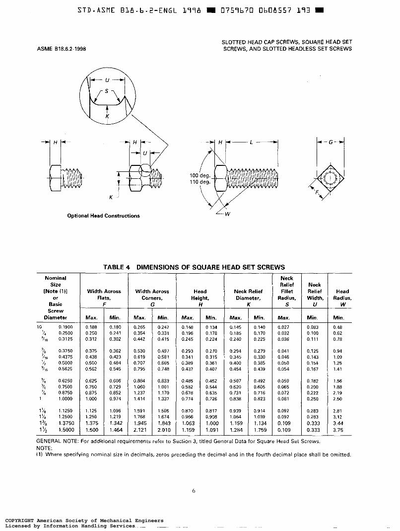
ASME 818.6.2-1998 SLOTTED HEAD CAP SCREWS, SQUARE HEAD SET SCREWS, AND SLOTTED HEADLESS SET SCREWS
K J
Optional Head Constructions
Nominal Size
[Note (1 11 or
Basic Screw
Diameter
10 0.1900 ’14 0.2500 5/16 0.3125
’18 0.3750
’12 0.5000 ’/16 0.5625
7/t6 0.4375
78 0.6250 3/4 0.7500
1 1 .o000
11/8 1.1250
78 0.8750
15h 1.2500 178 1.3750 172 1.5000
TABLE 4 DIMENSIONS OF SQUARE HEAD SET SCREWS
Width Across Neck Relief Head Width Across Flats, Diameter, Height, Corners,
F
Max. Max. Min.
0.188
0.442 0.302 0.312 0.354 0.241 0.250 0.265 0.180
0.375 0.362 0.530 0.438 0.423
0.795 0.545 0.562 0.707 0.484 0.500 0.619
0.625
1.414 0.974 1.000 1.237 0.852 0.875 1.060 0.729 0.750 0.884 0.606
1.125
2.121 1.464 1.500 1.945 1.342 1.375 1.768 1.219 1.250 1.591 1.096
Min.
0.247 0.331 0.415
0.497 0.581 0.665 0.748
0.833 1 .O01 1.170 1.337
1.505 1.674 1.843 2.010
h
Max.
0.148 O. 196 0.245
0.293 0.341 0.389 0.437
0.485 0.582 0.678 0.774
0.870 0.966 1.063 1.159
I
Min.
0.134 0.178 0.224
0.270 0.315 0.361 0.407
0.452 0.544 0.635 0.726
0.817 0.908 1 .o00 1.091
0.145
0.225 0.240 0.170 0.185 0.140
0.294
0.439 0.454 0.385 0.400 0.330 0.345 0.279
0.507
0.823 0.838 0.716 0.731 0.605 0.620 0.492
0.939
1.759 1.284 1.134 1.159 1.039 1 .O64 0.914
i Neck Relief Fillet
Radius, S
Max.
0.027 0.032 0.036
0.041 0.046 0.050 0.054
0.059 0.065 0.072 0.081
0.092 0.092 o. 109 0.109
Neck Relief Width,
U
Min.
0.083 0.100 0.111
0.125 0.143 0.154 0.167
O. 182 0.200 0.222 0.250
0.283 0.283 0.333 0.333
Head Radius,
W
Min.
0.48 0.62 0.78
0.94 1 .o9 1.25 1.41
1.56 1.88 2.19 2.50
2.81 3.12 3.44 3.75
GENERAL NOTE: For additional requirements refer to Section 3, titled General Data for Square Head Set Screws. NOTE: (1) Where specifying nominal size in decimals, zeros preceding the decimal and in the fourth decimal place shall be omitted.
6
COPYRIGHT American Society of Mechanical EngineersLicensed by Information Handling ServicesCOPYRIGHT American Society of Mechanical EngineersLicensed by Information Handling Services

S T D - A S M E B L B - b * Z - E N G L L798 U 13757b70 Ob08558 U Z T D
SLOTTED HEAD CAP SCREWS, SQUARE HEAD SET SCREWS. AND SLOTTED HEADLESS SET SCREWS
\
7 Flat Point
\ ~ I - L 4
l S l i g h t flat or rounding permissible
Nominal Size
[Note (311 or
Basic Screw Diameter
10 o. 1900 '/4 0.2500 5/16 0.3125 '/a 0.3750 '46 0.4375 '/z 0.5000
0.5625
'/a 0.6250 3/4 0.7500 '/a 0.8750
1 1 .o000 l'/a 1.1250 I '/4 1.2500 l'/a 1.3750 1 '/2 1.5000
- L 4 f
W
Cup Point
deg.
Max.
o. 1 o2 0.132 0.172 0.212 0.252 0.291 0.332
0.37 1 0.450 0.530 0.609 0.689 0.767 0.848 0.926
ASME B18.6.2-1998
Slight fillet permissible
radius permissible
Dog Point Half-Dog Point
,
Slight flat A Slight flat or permissible
See Note (2)
Oval Point Cone Point
TABLE 4 DIMENSIONS OF SQUARE HEAD SET SCREWS (CONT'D)
Cup and Flat Dog and Point Half-Dog Point
Diameters, Diameters, P
Min.
0.095 0.120 0.127 0.088
Max. Min. Max.
0.118 0.156 0.149 0.130 0.156 0.194
0.161 0.195 0.203
0.287 0.379 0.391 0.309 0.255 0.334 0.344 0.270 0.224 0.287 0.297 0.232 0.193 0.241 0.250
0.347
0.760 1.105 1.125 0.886 0.698 1.011 1.031 0.808 0.635 0.920 0.938 0.733 0.572 0.826 0.844 0.655 0.510 0.734 0.750 0.579 0.446 0.642 0.656 0.502 0.383 0.549 0.562 0.425 0.321 0.456 0.469
Min. Max.
0.085 0.050 0.120
0.1 14 0.214 0.099 0.183 0.083 O. 15 1 0.068
0.146 0.275 O. 130 0.245
0.305 0.164 0.367 0.196 0.430 0.227 0.490 0.260 0.552 0.291 0.615 0.323 0.678 0.354 0.740 0.385
Min.
0.040 0.058 0.073 0.089 O. 104 0.120 0.134
0.148 0.180 0.21 1 0.240 0.271 0.303 0.334 0.365
Oval Point
Radius, R
4.031 -0.000
0.142 0.188 0.234 0.281 0.328 0.375 0.422
0.469 0.562 0.656 0.750 0.844 0.938 1.031 1.125
Cone Point Angle: 90 deg. 2 2 deg.
for These Nominal Lengths
or Longer; 118 deg. * 2 deg.
for Shorter Screws, Y
GENERAL NOTE: For additional requirements refer to Section 3, titled General Data for Square Head Set Screws.
NOTES: (1) Point angle X shall be 45 deg. plus 5 deg., minus O deg. for screws of nominal lengths equal to or longer than those listed
(2) The extent of rounding or flat at the apex of the cone point shall not exceed an amount equivalent to 10% of the basic
(3) Where specifying nominal size in decimals, zeros preceding the decimal and in the fourth decimal place shall be omitted.
for variable Y, and 30 deg. minimum for screws of shorter nominal lengths.
screw diameter.
7
COPYRIGHT American Society of Mechanical EngineersLicensed by Information Handling ServicesCOPYRIGHT American Society of Mechanical EngineersLicensed by Information Handling Services

35
deg.
Flat
Po
int
Cup
Poin
t
.*5
deg.
Dog
Poin
t
I-‘--
Sligh
t fla
t pe
rmiss
ible
Oval
Poin
t
TABL
E 5
ILLU
STR
ATIO
N
. .
. .
Sligh
t fill
et
Fmlss
Tie
h
radiu
s pe
rmiss
ible
Half-
Dog
Poin
t
roun
ding
perm
issibl
Cone
Po
int
0 tr 0 CP
In ?I -I II- r
COPYRIGHT American Society of Mechanical EngineersLicensed by Information Handling ServicesCOPYRIGHT American Society of Mechanical EngineersLicensed by Information Handling Services

Nomi
nal
Size
[N
ote
(411
or
Basic
Sc
rew
Diam
eter
0 0.
0600
1
0.07
30
2 0.
0860
3 0.
0990
4
0.11
20
5 0.
1250
6 0.
1380
8
0.16
40
10
0.19
00
12
0.21
60
‘4 0.
2500
5/6
0.
3125
76
0.37
50
%6
0.43
75
% 0.
5000
g/5
0.56
25
5/s
0.62
50
23
0.75
00
TABL
E 5
DIM
ENSI
ON
S O
F SL
OTT
ED
HEA
DLE
SS
SET
SCR
EWS
Crow
n Ra
dius, I
[Note
(2
11
Basic
0.06
0 0.
073
0.08
6
Slot
W
idth,
Slot
De
h.
Cup
and
Fiat
Dog
Po
int
Point
Di
amete
rs,
Diam
eters,
C
P t
Point
?n
gth
DOS 0
I.
LI T Ha
lf-Do
g,
Max.
Min.
Ma
x. Mi
n.
Max.
Min.
Ma
x. Mi
n.
Max.
Min.
Ma
x. Mi
n.
0.01
4 0.
010
0.02
0 0.
016
0.03
3 0.
027
0.04
0 0.
037
0.03
2 0.
028
0.01
7 0.
013
0.01
6 0.
012
0.02
0 0.
016
0.04
0 0.
033
0.04
9 0.
045
0.04
0 0.
036
0.02
1 0.
017
0.01
8 0.
014
0.02
5 0.
019
0.04
7 0.
039
0.05
7 0.
053
0.04
6 0.
042
0.02
4 0.
020
Oval
Point
Ra
dius, R
[Note
(2
11
Basic
Cone
Po
int
Angle
: de
g. t
2 de
g. for
Th
ese
Nomi
nal
Leng
ths
or Lo
nger
; 11
8 de
g. t
2 de
g. for
Sh
orter
Sc
rews, Y
0.04
5 0.
055
0.06
4
0.09
9 0.
020
0.01
6 0.
028
0.02
2 0.
054
0.04
5 0.
066
0.06
2 0.
052
0.04
8 0.
027
0.02
3 0.
074
0.11
2 0.
024
0.01
8 0.
031
0.02
5 0.
061
0.05
1 0.
075
0.07
0 0.
058
0.05
4 0.
030
0.02
6 0.
084
0.12
5 0.
026
0.02
0 0.
036
0.02
6 0.
067
0.05
7 0.
083
0.07
8 0.
063
0.05
7 0.
033
0.02
7 0.
094
‘/s
%2
%6
0.13
8 0.
028
0.02
2 0.
040
0.03
0 0.
074
0.06
4 0.
092
0.08
7 0.
073
0.06
7 0.
038
0.03
2 0.
104
%6
0.16
4 0.
032
0.02
6 0.
046
0.03
6 0.
087
0.07
6 0.
109
0.10
3 0.
083
0.07
7 0.
043
0.03
7 0.
123
‘4
0.19
0 0.
035
0.02
9 0.
053
0.04
3 0.
102
0.08
8 0.
127
0.12
0 0.
095
0.08
5 0.
050
0.04
0 0.
142
%
0.21
6 0.
042
0.03
5 0.
061
0.05
1 0.
115
0.10
1 0.
144
0.13
7 0.
115
0.10
5 0.
060
0.05
0 0.
162
0.25
0 0.
049
0.04
1 0.
068
0.05
8 0.
132
0.11
8 0.
156
0.14
9 0.
130
0.12
0 0.
068
0.05
8 0.
188
0.31
2 0.
055
0.04
7 0.
083
0.07
3 0.
172
0.15
6 0.
203
0.19
5 0.
161
0.15
1 0.
083
0.07
3 0.
234
%6
%6
3/8
0.37
5 0.
068
0.06
0 0.
099
0.08
9 0.
212
0.19
4 0.
250
0.24
1 0.
193
0.18
3 0.
099
0.08
9 0.
281
‘I’6
0.43
8 0.
076
0.06
8 0.
114
0.10
4 0.
252
0.23
2 0.
297
0.28
7 0.
224
0.21
4 0.
114
0.10
4 0.
328
%
0.50
0 0.
086
0.07
6 0.
130
0.12
0 0.
291
0.27
0 0.
344
0.33
4 0.
255
0.24
5 0.
130
0.12
0 0.
375
‘46
0.56
2 0.
096
0.08
6 0.
146
0.13
6 0.
332
0.30
9 0.
391
0.37
9 0.
287
0.27
5 0.
146
0.13
4 0.
422
0.62
5 0.
107
0.09
7 0.
161
0.15
1 0.
371
0.34
7 0.
469
0.45
6 0.
321
0.30
5 0.
164
0.14
8 0.
469
0.75
0 0.
134
0.12
4 0.
193
0.18
3 0.
450
0.42
5 0.
562
0.54
9 0.
383
0.36
7 0.
196
0.18
0 0.
562
GENE
RAL
NOTE
S:
(a)
For
refer
ence
, se
e Ta
ble
5 illu
strat
ion
on
page
8.
tb)
For
addit
ional
requ
ireme
nts
refer
to Se
ction
4,
titled
Ge
nera
l Da
ta for
Sl
otte
d He
adles
s Se
t Sc
rews,
NOTE
S:
(I) Po
int
angle
X
shall
be
45
deg
. plu
s 5
deg.,
mi
nus
0 de
g. for
sc
rews
of no
mina
l len
gths
equa
l to
or lon
ger
than
those
lis
ted
for
varia
ble
b’, a
nd
30
deg.
minim
um
for
screw
s of
short
er no
mina
l len
gths.
(2)
Toler
ance
on
ra
dius
for
nomi
nal
sizes
up
to
and
includ
ing
5 (0
.125
in.)
shall
be
plu
s 0.
015
in.,
minu
s 0.
000
and
for
large
r siz
es,
plus
0.03
1 in.
, mi
nus
0.000
. Sl
otte
d en
ds
on
screw
s ma
y be
fla
t at
the
optio
n of
the
manu
factur
er.
(3)
The
exten
t of
roun
ding
or fla
t at
the
apex
of
the
cone
po
int
shall
no
t ex
ceed
an
am
ount
eq
uivale
nt
to 10
%
of the
ba
sic
screw
dia
meter
. (4)
W
here
spec
ifying
no
mina
l siz
e in
decim
als,
zeros
pr
eced
ing
the
decim
al an
d in
the
fourth
de
cimal
place
sh
all
be
omitte
d.
COPYRIGHT American Society of Mechanical EngineersLicensed by Information Handling ServicesCOPYRIGHT American Society of Mechanical EngineersLicensed by Information Handling Services

ASME 818.6.2-1998 SLOTTED HEAD CAP SCREWS, SQUARE HEAD SET SCREWS, AND SLOTTED HEADLESS SET SCREWS
TABLE 6 LENGTH TOLERANCES: SLOlTED HEAD CAP SCREWS Nominal Screw Size
Nominal Screw
'14 (0.250) through '116 (0.4375) through 'Is (0.875) through (0.375) 3/4 (0.750) ' 4 2 (1.500)
Length Length Tolerance
Through 1 (1.00) -0.03 Over 1 (1.00) through Zr/* (2.50) -0.04 Over 2'/2 (2.50) through 6 (6.00) -0.06 Over 6 (6.00) -0.12
-0.03 -0.06 -0.08 -0.12
-0.05 -0.10 -0.14 -0.20
shall screw at least two threads into a tapped hole counterbored to provide 0.03 1 in. of diametral clearance over the maximum body diameter, to a depth equal to the length of the gage shown in Appendix I. The tapped hole shall have Class 2B maximum pitch diameter, and the starting thread shall be countersunk to the diameter of the counterbore. The inspection fixture shall be hardened. For screw sizes over v' (0.750) in., the diametral clearance of the counterbore shall be 0.062 in.
2.6 Points
The end of cap screws shall be flat and chamfered from a diameter approximately 0.016 in. below the thread minor diameter to produce a length of chamfered or partial thread equivalent to '/2 to 1'/2 times the pitch of the thread.
2.7 Material
2.7.1 Steel. Unless otherwise specified, chemical and mechanical properties of steel slotted head cap screws shall conform to Grade A of ASTM A 307 or Grade 2 of SAE J429, or free machining steel meeting the mechanical properties of either of the previously mentioned materials.
Where so specified by the purchaser, screws may also be furnished conforming to Type 1 or 2 of ASTM A 449, to Grade 5 or 5.2 of SAE 5429, to Grade BD of ASTM A 354, or to Grade 8 or 8.2 of SAE J429.
2.7.2 Other Materials. Nonferrous materials are covered in ASTM F 468. Corrosion-resistant steels are covered in ASTM F 593.
2.8 Finishes
Unless otherwise specified, slotted head cap screws shall be supplied with a natural (as processed) finish, unplated or uncoated.
2.9 Workmanship
Slotted head cap screws shall be free from burrs, seams, laps, loose scale, and other surface irregularities that could affect their serviceability.
When control of surface discontinuities is required, the purchaser shall specify conformance to ASTM F 788F 788M.
2.10 Quality Assurance
Unless otherwise specified, acceptability of slotted head cap screws shall be determined in accordance with ASME B18.18.1M.
2.1 1 Dimensional Conformance
Products shall conform to the dimensions indicated in the applicable tables. Unless otherwise Specified, the following provisions shall apply for inspection of dimensional characteristics.
2.1 1.1 The following designated dimensional charac- teristics shall be inspected to the inspection levels shown according to ASME B 18.18.2M and shall be within their specified limits:
Designated Characteristic Inspection Level
Thread acceptability C Body diameter, E C Protrusion, F C
Thread length C Screw length, L C Visual inspection C
(of countersunk head)
(shall include fillet and workmm- ship)
If verifiable in-process inspection is used, inspection sample sizes and reporting shall be in accordance with the applicable ASME, ASTM, or SAE quality system consensus standard.
10
COPYRIGHT American Society of Mechanical EngineersLicensed by Information Handling ServicesCOPYRIGHT American Society of Mechanical EngineersLicensed by Information Handling Services

SLOTTED HEAD CAP SCREWS, SQUARE HEAD SET SCREWS, AND SLOTTED HEADLESS SET SCREWS ASME 618.6.2-1998
2.1 1.2 For nondesignated dimensional characteristics, 3.2 Length the provisions of ASME BI8.18.IM shall apply. If a nondesignated dimension is determined to be outside 3.2.1 Measurement. The length of square head its specified limits, it shall deemed conforming to set screws shall be measured parallel to the axis of this Standard if the user who is the installer accepts the screw from the intersection of the side of the head the dimension, based on form, fit, and function consider- with the undersurface to the extreme point. ations.
3.2.2 Length Tolerance. The length tolerance for square head set screws shall be as tabulated in Table 7.
2.12 Designation
Slotted head cap screws shall be designated by the following data, preferably in the sequence shown: prod- uct name; nominal size (fraction or decimal equivalent); threads per inch; screw length (fraction or decimal equivalent); material; protective finish, if required; or, optionally, ASME B18.24.1 PIN code. See examples below:
EXAMPLES: (1 ) Slotted Round Head Cap Screw, - 13 x 3, S A E Grade 2,
(2) Slotted Fiat Countersunk Head Cap Screw, 0.750 - 16 x 2.25, Zinc plated per ASTM B 633, FdZn 5 type I I .
ASTM F 593 Alloy Group I . S620NA39FAR26593AlABl.
3 GENERAL DATA FOR SQUARE HEAD SET SCREWS
3.1 Heads
3.1.1 Head Height. The head height specified on the dimensional table is measured, parallel to the axis of the screw, from the top of the head to the intersection of the side of the head with the undersurface.
3.1.2 Width Across Fiats. The maximum width across flats shall not be exceeded. On milled-from-bar, non-ferrous screws, however, the maximum limit may conform to commercial tolerances of the bar stock material. No transverse section through the head height shall be less than the specified minimum width across flats.
3.3 Threads
3.3.1 Thread Series and Class. The threads on square head set screws shall be Unified Inch coarse, fine, or 8 thread series, Class 2A, in accordance with ASME B1 . l . For threads with additive finish, the size limits of Class 2A apply before coating, and the thread after coating is subject to acceptance using a basic Class 3A size GO thread gage and a Class 2A thread gage for either minimum material or NOT GO.
3.3.2 Thread Gaging. Unless otherwise specified, dimensional acceptability of screw threads shall be determined based on System 21, ASME B1..3M.
3.4 Thread Length
Square head set screws shall have complete (full- form) threads extending over the portion of the screw length that is not affected by the point. For the respective constructions, threads shall extend into the neck relief, to the conical underside of head, or to within one thread (as measured with a thread ring gage) from the flat underside of the head. Threads through angular or crowned portions of points shall have fully formed roots with partial crests.
Because standard thread gages provide only for lengths of engagement up to 1v2 times the basic screw diameter, changes in pitch diameter of either or both the external and internal thread may be required for applications involving longer lengths of engagement.
3.5 Points
3.1.3 Head True Position. The axis of the head 3.5.1 Point Types. Unless otherwise specified, shall be located at true position within a tolerance zone square head set screws shall be supplied with cup having a diameter equal to 6% of the specified maximum points. Cup points as furnished by some manufacturers width across flats of the head, relative to the axis of may be externally or internally knurled. Where so the screw shank, regardless of feature size. The datum specified by the purchaser, screws shall have cone, shall be determined over a length from the head equal dog, half-dog, flat, or oval points conforming to specifi- to the basic screw diameter. cations in Table 4.
11
COPYRIGHT American Society of Mechanical EngineersLicensed by Information Handling ServicesCOPYRIGHT American Society of Mechanical EngineersLicensed by Information Handling Services

ASME 618.6.2-1998 SLOTrED HEAD CAP SCREWS, SQUARE HEAD SET SCREWS, AND SLOlTED HEADLESS SET SCREWS
TABLE 7 LENGTH TOLERANCES: SQUARE HEAD SET SCREWS ~~ ~~
Nominal Screw Size
10 (0.1901 through 3/4 (0.750) through '18 (0.625) 1'12 (1.500)
Nominal Screw Length Length Tolerance
Through 1 (1.00) -0.03 Over 1 (1.00) through 2 (2.00) -0.06 Over 2 (2.00) -0.09
-0.06 -0.12 -0.18
3.5.2 Point Angles. The external point angles spec- ified shall apply only to the portions of the point that lie below the thread root diameter, as angles within the thread profile may vary due to manufacturing processes.
3.5.3 Dog Points. Dog points are not supplied on screws where the length of usable (effective) thread is less than the basic screw diameter. Half-dog points should be specified for such screw lengths.
3.5.3.1 Point True Position. The axis of the dog of half-dog points shall be at true position with respect to the axis of the thread within a tolerance zone having a diameter of 0.010 in. for sizes up to and including "/, (0.750) in. and a diameter of 0.020 in. for larger sizes, regardless of feature size.
3.6 Material
Unless otherwise specified by the purchaser, square head set screws shall be made from case hardened steel or through hardened steel as follows, at the option of the supplier.
3.6.1 Case Hardened Steel. Unless otherwise specified, case hardened steel square head set screws shall be low carbon steel, case hardened to 83 HRI5N minimum, with the following case depth:
Diameter Case Depth
No. 10 0. 190 0.004-0.009 Y& 1 Y> 0.250-1 S00 0.006 min.
3.6.2 Through Hardened Steel. Unless otherwise specified, through hardened steel square head set screws shall be alloy steel, quenched, and tempered to a hardness of 45-53 HRC (450-560 HV or 428-532 HB), with a surface hardness at least equal to the core hardness, but not exceeding 88 HRl5N.
3.6.3 Other Materials. Where so specified by the purchaser, square head set screws may be made from corrosion resistant steel or nonferrous metals. The mate-
rials and properties shall be as agreed upon between the manufacturer and purchaser.
3.7 Finish
Unless otherwise specified, set screws shall be sup- plied with a natural (as processed) finish, unplated or uncoated.
3.8 Workmanship
Square head set screws shall be free from burrs, seams, laps, loose scale, and any other defects that could affect their serviceability.
3.9 Quality Assurance
Unless otherwise specified, acceptability of square head set screws shall be determined in accordance with ASME B18.18.1M.
3.10 Dimensional Conformance
Products shall conform to the dimensions indicated in the respective tables. Unless otherwise specified, the following provisions shall apply for inspection of dimensional characteristics.
3.10.1 The following dimensional characteristics shall be inspected to the inspection levels shown ac- cording to ASME B18.18.2M and shall be within their specified limits:
Designated Characteristic Inspection Level
Thread acceptabllity C Head width across comers C Screw length, L C Visual inspection (shall include C
fillet and workmanship)
If verifiable in-process inspection is used, inspection sample sizes and reporting shall be in accordance with the applicable ASME, ASTM, or SAE quality system consensus standard.
12
COPYRIGHT American Society of Mechanical EngineersLicensed by Information Handling ServicesCOPYRIGHT American Society of Mechanical EngineersLicensed by Information Handling Services

SLOlTED HEAD CAP SCREWS, SQUARE HEAD SET SCREWS, AND SLOTTED HEADLESS SET SCREWS ASME 818.6.2-1998
3.10.2 For nondesignated dimensional characteristics, TABLE 8 LENGTH TOLERANCES: SLOlTED the provisions of ASME B18.18.1M shall apply. If a HEADLESS SET SCREWS nondesignated dimension is determined to be outside Nomina, Screw Length its specified limits, it shall be deemed conforming to
Length Tolerance
this Standard if the user who is the installer accepts Through 1 (1.00) -0.03 the dimension, based on form, fit, and function consider- Over through (2*oo) -0.06 ations. Over 2 (2.00) -0.09
3.1 1 Designation
Square head set screws shall be designated by the following data, preferably in the sequence shown: prod- uct name; nominal size (number, fraction, or decimal equivalent); threads per inch; screw length (fraction or decimal equivalent); point style; material; protective finish, if required; or optionally, ASME B18.24.1 PIN code. See examples below:
EXAMPLES: ( I ) Square Head Set Screw, '/4 - 20 x Vd, Flat Point, Steel, Zinc
plated per ASTM B 633 Fe/Zn 5 type I I , S620NB35CAD14155NNCEI.
(2) Square Head Set Screw, 0.250 - 20 x 0.75, Cup Point, Through Hardened Steel, Zinc plated per ASTM B 633 Fe/Zn 5 type 11, S620NB33CAD14303NNCEI.
(3) Square Head Set Screw, 0.500 - 13 x 1.25, Cone Point, 303 Corrosion Resistant Steel, Hardness 70 - 95 HRB, Passivated per ASTM A 380, S620NB34CAM19406NNAB I ,
4 GENERAL DATA FOR SLOlTED HEADLESS SET SCREWS
4.1 Headless Ends
4.1.1 End Configuration. The slotted end of screws may be crowned as depicted and dimensioned in Table 5 or may be flat, at the option of the manufacturer.
4.1.2 Slot Depth. The slot depth in slotted headless set screws shall be measured, parallel to the axis of the screw, from the end of the screw to the intersection of the bottom of the slot with the thread major diameter.
4.2 Length
4.2.1 Measurement. The length of headless set screws shall be measured overall, parallel to the axis of the screw.
4.2.2 Length Tolerance. The length tolerance for slotted headless set screws shall be as tabulated in Table 8.
4.3 Threads
4.3.1 Thread Series and Class. The threads on slotted headless set screws shall be Unified Inch coarse, fine, or 8 thread series, Class 2A, in accordance with ASME B 1 . l . For threads with additive finish, the size limits of Class 2A apply before coating, and the thread after coating is subject to acceptance using a basic Class 3A size GO thread gage and a Class 2A thread gage for either minimum material or NOT GO.
4.3.2 Thread Gaging. Unless otherwise specified, dimensional acceptability of screw threads shall be determined based on System 21, ASME B 1.3M.
4.4 Thread Length
Slotted headless set screws shall have complete (full- form) threads extending over the portion of the screw length that is not affected by the point or the crown on the headless end. Threads through angular or crowned portions of length shall have fully formed roots with partial crests.
Because standard thread gages provide only for lengths of engagement up to 11/2 times the basic screw diameter, changes in the pitch diameter of either or both the external and internal thread may be required for applications involving longer lengths of engagement.
4.1.3 Slot True Position. The slot in slotted head- 4.5 Points
less set screws shall be located at true position relative 4.5.1 Point Types. Unless otherwise specified, slot- to the axis of the thread within a tolerance zone having ted headless set screws shall be supplied with cup a width equal to 12% of the basic screw diameter points. Where so specified by the purchaser, screws or to 0.020 in., whichever is greater, regardless of shall have cone, dog, half-dog, flat, or oval points feature size. conforming to specifications in Table 5.
13
COPYRIGHT American Society of Mechanical EngineersLicensed by Information Handling ServicesCOPYRIGHT American Society of Mechanical EngineersLicensed by Information Handling Services

ASME 818.6.2-1998
4.5.2 Point Angles. The external point angles spec- ified shall apply only to the portions of the point that lie below the thread root diameter, as angles within the thread profile may vary due to manufacturing processes.
4.5.3 Dog Points. Dog points are not supplied on screws where the length of usable (effective) thread is less than the basic screw diameter. Half-dog points should be specified for such screw lengths.
4.5.3.1 Point True Position. The axis of the dog or half-dog points shall be located at true position with respect to the axis of the thread within a tolerance zone equal to 6% of the basic screw diameter or 0.010 in., whichever is less, regardless of feature size.
4.6 Material
Unless otherwise specified by the purchaser, slotted headless set screws shall be made from case hardened steel or through hardened steel as follows, at the option of the supplier.
4.6.1 Case Hardened Steel. Unless otherwise specified, case hardened steel slotted headless set screws shall be low carbon steel, case hardened to 83 HRl5N minimum, with the following case depth:
Diameter Case Depth
Nos. 2 4 0.08M. 138 0.002-0.007 Nos. 8-12 0.164-0.216 0.004-0.009
'/&V4 0.250-0.750 0.006 min.
4.6.2 Through Hardened Steel. Unless otherwise specified, through hardened steel slotted headless set screws shall be alloy steel, quenched, and tcmpered to a hardness of 45-53 HRC (450-560 HV or 428-532 HB), with a surface hardness at least equal to the core hardness, but not exceeding 88 HR15N.
4.6.3 Other Materials. Where so specified by the purchaser, slotted headless set screws may be made from corrosion resistant steel or nonferrous metals. The materials and properties shall be as agreed upon between the manufacturer and purchaser.
SLOTTED HEAD CAP SCREWS, SQUARE HEAD SET SCREWS, AND SLOTTED HEADLESS SET SCREWS
4.7 Finish
Unless otherwise specified, set screws shall be sup- plied with a natural (as processed) finish, unplated or uncoated.
4.8 Workmanship
Slotted headless set screws shall be free from burrs, seams, laps, loose scale, and other surface irregularities that may affect their serviceability.
4.9 Quality Assurance
Unless otherwise specified, acceptability of slotted headless set screws shall be determined in accordance with ASME B18.18.1M.
4.10 Dimensional Conformance
Products shall conform to the dimensions indicated in the respective tables. Unless otherwise specified, the following provisions shall apply for inspection of dimensional characteristics.
4.10.1 The following designated dimensional charac- teristics shall be inspected to the inspection levels shown according to ASME B18.18.2M and shall be within their specified limits:
Designated Characteristic Inspection Level
Thread acceptability C Screw length, L C Visual inspection C
If verifiable in-process inspection is used, inspection sample sizes and reporting shall be in accordance with the applicable ASME, ASTM, or SAE quality system consensus standard.
4.10.2 For nondesignated dimensional characteristics, the provisions of ASME B18.18.lM shall apply. If a nondesignated dimension is determined to be outside its specified limits, it shall be deemed conforming to this standard if the user who is the installer accepts the dimension, based on form, fit, and function consider- ations.
4.1 1 Designation
Slotted headless set screws shall be designated by the following data, preferably in the sequence shown: product name; nominal size (number, fraction, or deci-
14
COPYRIGHT American Society of Mechanical EngineersLicensed by Information Handling ServicesCOPYRIGHT American Society of Mechanical EngineersLicensed by Information Handling Services
SLOTTED HEAD CAP SCREWS, SQUARE HEAD SET SCREWS, AND SLOTTED HEADLESS SET SCREWS
mal equivalent); threads per inch; screw length; point style; material; protective finish, if required; or option- ally, ASME B18.24 PIN code. See examples below:
EXAMPLES: Slotted Headless Set Screw, y4 - 20 x V2, Cup Point, Steel, Zinc
plated per ASTM B 633 FelZn 5 type II , S620NB27CAD10155NNCEI.
Slotted Headless Set Screw, 190 - 32 x 0.38, Oval Point, Through Hardened Steel. S620NB32FAA08303NNAAl.
ASME B18.6.2-1998
15
COPYRIGHT American Society of Mechanical EngineersLicensed by Information Handling ServicesCOPYRIGHT American Society of Mechanical EngineersLicensed by Information Handling Services
STD-ASME B L B - b - Z - E N G L 1198 0757b7CI CIbO85b7 032 I
SLOTTED HEAD CAP SCREWS, SQUARE HEAD SET SCREWS, AND SLOTTED HEADLESS SET SCREWS ASME 618.6.2-1998
APPENDIX I THREAD RUNOUT SLEEVE GAGES FOR SLOTTED HEAD CAP SCREWS
(This Appendix is part of ASME 818.6.2-1998.)
Gages capable of checking the thread eccentricity and angularity respective to the axis of slotted head cap screws are illustrated on the following page.
The lower construction permits the use of various length sleeves to accommodate different screw lengths. Thread ring gage A is centered on sleeve B by means of positioning plug E and is secured in position by means of attachment screws C. The ring gage is also set to Class 2B maximum pitch diameter by use of positioning plug E.
Diameter D, of counterbore or hole in sleeve, shall be equal to the basic (nominal) diameter of the screw plus the specified runout allowance. The sleeve length or counterbore depth L should be such that the entering face of the gage extends beyond the last thread on the screw to be inspected but for practical purposes should not exceed 3.00 in.
Failure of the screw to enter the threads of the gage for at least two threads or interference between the sides of the hole or counterbore and the screw while engaging the threads of gage indicates excessive thread runout.
COPYRIGHT American Society of Mechanical EngineersLicensed by Information Handling ServicesCOPYRIGHT American Society of Mechanical EngineersLicensed by Information Handling Services

ASME 818.6.2-1998
Countersink to diameter D /
LClass 2B maximum pitch diameter thread
Optional Constructions
SLOTTED HEAD CAP SCREWS, SQUARE HEAD SET SCREWS, AND SLOTTED HEADLESS SET SCREWS
D
I I Countersink to
D
Class 26 maximum pitc +o.oooo
E diameter thread
GENERAL NOTES: (a) To ensure adequate service life, gages shall be suitably hardened. (b) Nomenclature is as follows:
A = thread ring gage set to Class 28 maximum pitch diameter B = sleeve C = attachment screws D = basic diameter of screw plus diametral clearance allowance E = positioning and setting plug for adjusting ring gage to Class 2B maximum pitch diameter and
L = depth of counterbore or length of sleeve equals length of screw minus twice the basic diameter centering sleeve
of the screw but for practical purposes should not exceed 3.00 in.
18
COPYRIGHT American Society of Mechanical EngineersLicensed by Information Handling ServicesCOPYRIGHT American Society of Mechanical EngineersLicensed by Information Handling Services
S ' T D - A S M E BLB*b-Z -ENGL L718 W CI757b7U ClbCl85b9 705 W
SLOTTED HEAD CAP SCREWS, SQUARE HEAD SET SCREWS, AND SLOTTED HEADLESS SET SCREWS ASME B18.6.2-1998
APPENDIX II PROTRUSION GAGING OF FLAT COUNTERSUNK HEAD CAP SCREWS
(This Appendix is part of ASME 818.6.2-1998.)
Suitability of slotted flat countersunk head cap screws for application in countersinks designed to the principal dimensions of the screws may be tested by use of a protrusion gage as illustrated on the following page.
The gaging dimensions and the gage diameters are specified in the dimensional table for flat countersunk head cap screws. The protrusion limits shown in the table shall apply only when the gaging diameter is exactly as indicated with the gaging edge of a sharpness obtained by lapping the hole and the top surface of the gage. Any variation in the gaging diameter will require recalculation of protrusion values by the original formulas given on the following page.
19
COPYRIGHT American Society of Mechanical EngineersLicensed by Information Handling ServicesCOPYRIGHT American Society of Mechanical EngineersLicensed by Information Handling Services

ASME B18.6.2-1998 SLOTTED HEAD CAP SCREWS, SQUARE HEAD SET SCREWS, AND SLOTTED HEADLESS SET SCREWS
GE
c' t g e
thickness optional 2
Maximum Protrusion [Note (l)]: Max. Sharp Head Diameter - Gage Hole Diameter
Max. F = x tan 90" - i Min. Head Angle 2 2
Minimum Protrusion [Note ( I ) ] :
i Min. Sharp Head Diameter [Note (2) l - Gage Hole Diameter 2
or correction of protrusion in accordance with the following formula: Min. F =
Max. Head Angle 2 x tan 90" -
F = F - A - G A - G
Where: F = tabulated protrusion value F' = corrected protrusion value A = head diameter (maximum or minimum for maximum or minimum
protrusion, respectively) G = tabulated gage diameter G = measured gage diameter
:NER AL NOTE: To ensure adequate service life, the protrusion gage should be made of tool steel having a hardness not less than 60 Rockwell C.
NOTES: (1) Protrusion values shown in dimensional tables were calculated from these formulas and rounded to the nearest 0.001
in., upward for the maximum, and downward for the minimum. (2) See formulas for minimum sharp head diameter in Appendix A.
20
COPYRIGHT American Society of Mechanical EngineersLicensed by Information Handling ServicesCOPYRIGHT American Society of Mechanical EngineersLicensed by Information Handling Services

APPENDIX A FORMULAS FOR DIMENSIONS
(This Appendix is not part of ASME B18.6.2-1998 and is provided for informational purposes only.)
21
COPYRIGHT American Society of Mechanical EngineersLicensed by Information Handling ServicesCOPYRIGHT American Society of Mechanical EngineersLicensed by Information Handling Services

Scre
w Si
ze
‘/d t
hrou
gh
“1s
TABL
E A.
1 SL
OTT
ED
FLAT
CO
UN
TER
SUN
K H
EAD
CAP
SC
REW
S
Head
Di
amete
r He
ad
Heigh
t
Max.
A =
2.00
0 D
to sh
arp
corne
r Mi
n.
A =
1.84
0 D
- 0.
008
with
ro
und
or fla
t Ma
x. H
= 0.
596
D Ga
ging
diam.
G
= 1.
810
D 0.
028
Min.
H
= 0.
541
D 0.
005
[Note
(1
)l Mi
n.
A =
1.94
0 D
- 0.
008
to sh
arp
corne
r [N
ote
(1)l
Slot
De
pth
Max.
T =
0.27
4 U
Min.
T
= 0.
188
D-
0.00
2
‘4s
Max.
A =
2.00
0 D
- 0.0
63
to sh
arp
corne
r Mi
n.
A =
1.84
0 D
0.06
9 wi
th
roun
d or
flat
Gagin
g dia
m.
G =
1.81
0 D
- 0.
089
Min.
A
= 1.
940
D 0.
069
to sh
arp
corne
r [N
ote
(I)1
Max.
H =
0.59
6 D
- 0.
0375
Ma
x. T
= 0.
274
D -
0.01
7 Mi
n.
H =
0.54
1 D
- 0.0
40
[Note
(I)
1 Mi
n.
T =
0.18
8 D
- 0.0
14
‘/s t
hrou
gh
1
Max.
A =
2.00
0 D
- 0.1
25
to sh
arp
corne
r Mi
n.
A =
1.84
0 D
0.12
9 wi
th
roun
d or
flat
Gagin
g dia
m.
G =
1.81
0 D-
0.
149
Min.
A
= 1.
940
D -
0.12
9 to
sharp
co
rner
(Note
(1
)l
Max.
H =
0.59
6 D
- 0.
075
Min.
H
= 0.
541
D - 0
.074
IN
ote
(1)l
Max.
T=
0.27
4 D-
0.
034
Min.
T
= 0.
188
D - 0
.026
I’/*
throu
gh
I’/z
Max.
A =
2.00
0 D
- 0.
188
to sh
arp
corne
r Mi
n.
A =
1.84
0 D
- 0.
190
with
ro
und
or fla
t Ga
ging
diam.
G
= 1.
810
D -
0.21
0 Mi
n.
A =
1.94
0 iY
- 0.
190
to sh
arp
corne
r [N
ote
Cl)1
Max.
H =
0.59
6 D
- 0.
112
Min.
H
= 0.
541
D -
0.10
9 [N
ote
(1))
Max.
T =
0.27
4 D
- 0.
051
Min.
T
= 0.
188
D -
0.03
8
GENE
RAL
NOTE
: D
= ba
sic
diame
ter
of the
sc
rew
NOTE
: (1)
Va
lues
are
no
longe
r ta
bulat
ed;
formu
las
are
retai
ned
here
for
re
feren
ce
only.
COPYRIGHT American Society of Mechanical EngineersLicensed by Information Handling ServicesCOPYRIGHT American Society of Mechanical EngineersLicensed by Information Handling Services

TABLE A.2 SLOTTED ROUND HEAD CAP SCREWS
Screw Size Head Diameter Head Height Slot Depth
'I4 and 5/16 Max. A = 2.000 D - 0.063 Min. A = 1.960 D - 0.072
"/B and 'il6 Max. A = 2.000 D - 0.125 Min. A = 1.960 D - 0.132
5; and Max. A = 2.000 D - 0.1875 Min. A = 1.960 D - 0.1935
"/B and 3/4 Max. A = 2.000 D - 0.250 Min. A = 1.960 D - 0.255
GENERAL NOTE: D = basic diameter of the screw
Max. H = 0.875 D - 0.028 Min. H = 0.815 D - 0.029
Max. H = 0.875 D - 0.055 Min. H = 0.815 D - 0.054
Max. H = 0.875 D - 0.083 Min. H = 0.815 D - 0.080
Max. H = 0.875 D - 0.1 10 Min. H = 0.815 D - 0.104
TABLE A.3 SLOlTED FILLISTER HEAD CAP SCREWS
~ ~~
Max. T = 0.543 D - 0.019 Min. T = 0.463 D - 0.019
Max. T = 0.543 D - 0.036 Min. T = 0.463 D - 0.036
Max. T = 0.543 D - 0.053 Min. T = 0.463 D - 0.053
Max. T = 0.543 D - 0.069 Min. T = 0.463 D - 0.069
Screw Size Head Diameter
'/4 and 'h6 Max. A = 1.000 D + 0.125 Min. A = 0.980 D + 0.118
Ya and Max. A = 1.000 D + 0.1875 Min. A = 0.980 D + 0.180
through Max. A = 1.000 D + 0.250 Min. A = 0.980 D + 0.241
1 Max. A = 1.000 D + 0.3125 Min. A = 0.980 D + 0.302
Head Side Height
Max. H = 0.660 D to nearest '/@ in. Min. H = Max. H - (0.030 D + 0.008)
Max. H = 0.660 D t o nearest '& in. Min. H = Max. H - (0.030 D + 0.010)
Max. H = 0.660 D to nearest '/, in. Min. H = Max. H - (0.030 D + 0.012)
Max. H = 0.660 D to nearest '/, in. Min. H = Max. H - (0.030 D + 0.014)
Oval Heiaht
Max. F = 0.110 D + 0.016 Min. F = 0.100 D + 0.0125
Max. F = 0.1 10 D + 0.023 Min. F = 0.100 D + 0.018
Max. F = 0.1 10 D + 0.030 Min. F = 0.100 D + 0.025
Max. F = 0.1 10 D + 0.037 Min. F = 0.100 D + 0.031
Screw Size Total Head Height Slot Depth
through 1 Max. O = Max. F + Max. H Max. T = 0.500 (Min. F + Min. M Min. O = Min. F + Min.. H Min. T = Max. T - 0.080 D
GENERAL NOTE: D = basic diameter of the screw
23
COPYRIGHT American Society of Mechanical EngineersLicensed by Information Handling ServicesCOPYRIGHT American Society of Mechanical EngineersLicensed by Information Handling Services
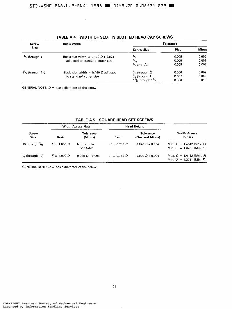
TABLE A.4 WIDTH OF SLOT IN SLOTTED HEAD CAP SCREWS
Screw Basic Width Tolerance Size Screw Size Plus Minus
'/4 through 1 Basic slot width = 0.160 D + 0.024 7 4
adjusted to standard cutter size 5 11 6 and 7/16
0.005 0.006 0.005 0.007 0.005 0.008
through 1 y2 Basic slot width = 0.160 D adjusted through 0.006 0.009 to standard cutter size "/4 through 1 0.007 0.009
through Il/* 0.008 0.010
GENERAL NOTE: D = basic diameter of the screw
TABLE A.5 SQUARE HEAD SET SCREWS
Screw Size
Width Across Flats Head Height
Tolerance Tolerance Width Across Basic (Minus) Basic (Plus and Minus) Corners
10 through 5/16 F = 1.000 D No formula, H = 0.750 D 0.020 D + 0.004 Max. G = 1.4142 (Max. R see table Min. G = 1.373 (Min. F)
'/a through 11/2 F = 1.000 D 0.020 D + 0.006 H = 0.750 D 0.020 D + 0.004 Max. G = 1.4142 (Max. F) Min. G = 1.373 (Min. R
GENERAL NOTE: D = basic diameter of the screw
24
COPYRIGHT American Society of Mechanical EngineersLicensed by Information Handling ServicesCOPYRIGHT American Society of Mechanical EngineersLicensed by Information Handling Services
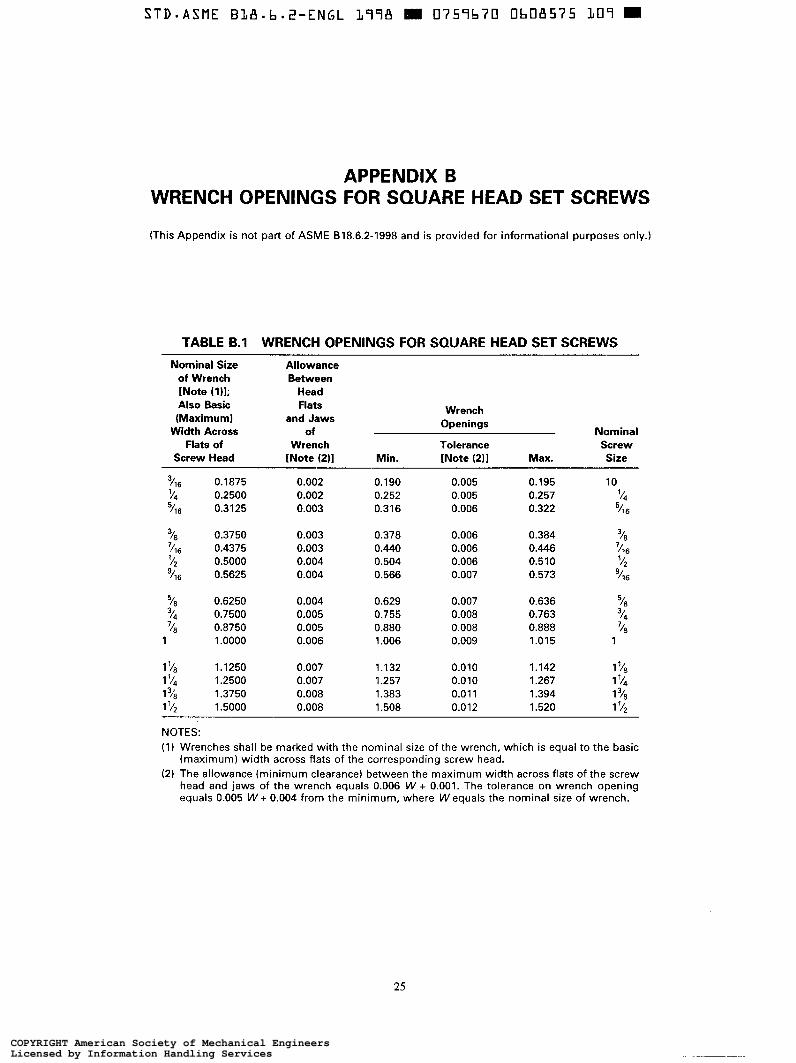
APPENDIX B WRENCH OPENINGS FOR SQUARE HEAD SET SCREWS
(This Appendix is not part of ASME 818.6.2-1998 and is provided for informational purposes only.)
TABLE 6.1 WRENCH OPENINGS FOR SQUARE HEAD SET SCREWS
Nominal Size of Wrench [Note (111; Also Basic (Maximum)
Width Across Flats of
Screw Head
3 0.1875 0.2500
5/16 0.3125
Allowance Between
Head Flats
and Jaws Wrench
Openings
Wrench Tolerance Screw of Nominal
[Note (211 Min. [Note (211 Max. Size
0.002 0.190 0.005 0.195 10
0.003 0.316 0.006 0.322 0.002 0.252 0.005 0.257 '14
5 11 6
3
7/16 0.4375 0.003 0.440 0.006 0.446 18 0.3750 0.003 0.378 0.006 0.384 "8
'116 '/z 0.004 0.504 0.006 0.510 5;
98 0.6250 0.004 0.629 0.007 0.636 v* 14 0.7500 0.005 0.755 0.008 0.763 14
18 0.8750 0.005 0.880 0.008 0.888 '18
1 '/B 1.1250 0.007 1.132 0.0 1 o 1.142 1 '/a 1 '/4 1.2500 0.007 1.257 0.010 1.267 1 '/4 1 1.3750 0.008 1.383 0.01 1 1.394 1 3//B
1 '/2 1.5000 0.008 1.508 0.012 1.520 1 '/2
0.5000 '/16 0.5625 0.004 0.566 0.007 0.573 9
I 1 6
3
7
3
1 1 .o000 0.006 1 .O06 0.009 1.015 1
NOTES: (1) Wrenches shall be marked with the nominal size of the wrench, which is equal to the basic
(maximum) width across flats of the corresponding screw head. (2) The allowance {minimum clearance) between the maximum width across flats of the screw
head and jaws of the wrench equals 0.006 W + 0.001. The tolerance on wrench opening equals 0.005 W + 0.004 from the minimum, where W equals the nominal size of wrench.
25
COPYRIGHT American Society of Mechanical EngineersLicensed by Information Handling ServicesCOPYRIGHT American Society of Mechanical EngineersLicensed by Information Handling Services

ASME Services
ASME is committed to developing and delivering technical information. At ASME’s Information Central, we make every effort to answer your questions and expedite your orders. Our representatives are ready to assist you in the following areas:
ASME Press Member Services & Benefits Codes & Standards Other ASME Programs Credit Card Orders Payment Inquiries IMechE Publications Professional Development Meetings & Conferences Short Courses Member Dues Status Publications
Public Information Self-study Courses Shipping Information SubscriptionslJournalsMagazines Symposia Volumes Technical Papers
HQW can you reach us? It’s easier than ever!
There are four options for making inquiries* or placing orders. Simply mail, phone, fax, or E-mail us an3 an Information Central representative will handle your request.
Mail Call Toll Free Fax-24 hours E-Mail-24 hours ASME US ¿?L Canada: 800-THE-ASME 973-882- 17 17 Infocentral 22 Law Drive, Box 2900 (800-843-2763) 973-882-5155 @asme.org Fairfield, New Jersey Mexico: 95-800-THE-ASME 07007-2900 (95-800-843-2763)
Universal: 973-882-1 167
* Information Centrd staff are not permitted to answer inquiries about the technical content of this code or standard. Information as to whether or not technical inquiries are issued to this code or standard is shown on the copyright page. All technical inquiries must be submitted in writing to the staff secretary. Additional procedures for inquiries may be listed within.
COPYRIGHT American Society of Mechanical EngineersLicensed by Information Handling ServicesCOPYRIGHT American Society of Mechanical EngineersLicensed by Information Handling Services
Related Documents