1 A S I C D e s i g n P r o c e s s • Foundry and Process Technology • High level Model - Algorithm evaluation • Design in RTL • Design verification • Syntesis • Test DFT • Backend • Samples • Qualification • Production

Welcome message from author
This document is posted to help you gain knowledge. Please leave a comment to let me know what you think about it! Share it to your friends and learn new things together.
Transcript

1
ASIC Design Process
• Foundry and Process Technology• High level Model - Algorithm evaluation• Design in RTL • Design verification• Syntesis• Test DFT• Backend• Samples• Qualification• Production

2
Network IC’s
• Network chips• PHY & Interfaces• Single Chip Switches / Routers• Multi Chip Switches / Routers• Network Processors• Future of Networking IC’s?
Foundry and Process Technology
• Main foundry today are Taiwan Semiconductor Manufacturing Company(TSMC) and United Microelectronics Corporation (UMC)
• 0.13 avalible Today – TSMC,UMC• 0.10 first tapeout in Q1 2002 - TSMC• 0.10 risk production in Q4 2002 – TSMC• UMC,TSMC treats smaller customers better
(startup’s etc)

3
Foundry and Process Technolgy
• Gates to syntesize against? Artisan, Virtual Silicon etc
• Memory compilers? (SRAM,ROM,RF)• Have been silicon taped out before?• What qualification process?• Worst case and Best case timing? Which to
use? Can we use nominal timing?
Foundry and Process Technology
• Which process to use? 0.25 , 0.18, 0.13, 0.10?• Estimated Tape Out date?• Price for tapeout? Number of chips?
NA guess $6000
$4000$2850$1800Wafer Cost
9-10?865Metal Layers
Est $1.5M to $2.0M
$650.000$300.000$130.000Mask Set
TSMC
0.10um
TSMC
0.13 um
TSMC
0.18 um
UMC
0.25 um
Feature / Process

4
Foundry and Process Technology
• Differance between each level:• 0.25 to 0.18 , Area = ½, Power = ½, Timing 30%
better• 0.18 to 0.13 , Area = ½, Power = ½, Timing 30%
better• 0.13 to 0.10 , Area = ½, Power = ½, Timing 30%
better• Why is timing not improving at same rate?
High Level Model
• Can use C/C++ to evaluate alorithms for chip• Exists languages which are made for high level of
”hardware design” , VHDL started as one!• SystemC is such a language• From high level a cycle acurate simulator can be built to
verify that it is indeed possible to build• Verilog and VHDL has interface to use a external
procedure instead of a internal one – Possible to use C in some parts while real RTL code in other parts

5
Design in RTL
• At SwitchCore we use Emacs for design entry• There exists several tools which helps the design entry• Visual HDL and EASE are two tools for graphical
design entry• Why are not SwitchCore using thouse tools? Cost and
once one starts to use them all people have to use them....
• How much productivity does they add?• How much more problems will they cause?
Design in RTL
• Learn PERL and TCL• Usefull when doing text processing• Large netlists or preprocessor to your
testbenches• tcl are used in Synopsys tools which is de facto
standard in ASIC world• A designers way is usually alot of batch work
which can be automated with scripts

6
Clock and Reset
• Always try to use as few clock domains as possible
• When going from one clock domain to another use safe methonds...
• Use one reset to reset everything (Registers, state machines etc.) then another reset which resets all the functions but keeps the registers intact, this means that if something goes wrong only part of the design is restarted
Simulation
• We use ModelSim for simulation• Simulation on both rtl and netlist with
backanotated timing (SDF)• Simulations have NEVER caught any timing
errors all timing errors has been caugth in Static time analasys
• Simulation in netlists is very slow while large RTL designs more okey

7
Design Verification
• Block designers design a block are also responsible for its function and that the testbench is actually testing all its features
• Then we have multiblock testbenches which test a number of blocks; i.e out Queue Engine constists of Inqueue handler,Linker and Scheduler and Enqueuer
• Random tests are important• How do you know when you have verified all the
functionality?• Try to keep block designs as ”free” from each other as
possible no signals should come in at a unexpected time and change state machines etc..
Design Verification
• When do you know that you have verified enough?• Would something called Line coverage tell you that you
have verified enough?• If your block is failing your company might risk loosing
millions of $$$$• Perhaps a co-designer would be a idea? • Co-designer would write your block test bench and you
would write his? From a risk view if something happens a person could be replaced with the co-designer

8
Design Verification
• We also have a top test bench to run a larger regresstion suite to test functionality which cover a number of blocks
• Testbench is written in C and Verilog• Testbench holds a ”score board” which says
where packets should come out and how they should look like
• Takes about a week to run on netlists while only about 24 hours in RTL .... Try to keep as much as possible in RTL simulations !
Design Verification
• Did SwitchCore verify enough?
Feature 1
Feature 2
Feature 3
Feature 4
Feature 1
Feature 2
Feature 3
Feature 4
Have we covered all combinations?

9
Design Verification
• Needed new verification which involves more random testing..
• New language and tool introduced, e and specman verification language, help from Intel and verification team in Israel
• Define a number of functional coverage points (FCP) in verilog code
• Run random test to cover all aspects of FCPs• What is a FCP?
FCP - Events
• FCP are made to trigger and check that a number of events has occured at the same time
event send_pause is rise(`send_pause´)@clkcover sent_pause is {
item rx_send_pause : boot = TRUE usingignore = (rx_send_pause==FALSE)
}
This event checks if a signal has been high during simulation

10
FCP - Crossing itemChecking that a FIFO/SRAM has been at all places
event gifrxfifo_0 is change(‘DataCtl[5:0]´)@clk150cover gifrxfifo_0 is {
Item rx_fifo_depth : uint(bits:6) = ’DataCtr[5:0]’ usingillegal = (rx_fifo_depth > 29),ranges = {
range([0..15],”30% full”);range([16..22],”50% full”);range([23..28],”80% full”);};
item fifo_number : uint = fifo_number;cross fifo_number,rxfifo_depth;
};
FCP State MachinesTarSt :
[SLAVE_DUMMY_WRITE=1,SLAVE_DUMMY=2,SLAVE_DATA=4,SLAVE_READ=8,SLAVE_ADDR=16];
Event TARState_change is @clk60
Cover TARState_change is {Item TSt : TarSt = ’THXSlaveState’;Transition TSt using illegal = Not (
(prev_TSt == SLAVE_ADDR and TSt == SLAVE_READ) or(prev_TSt == SLAVE_READ and TSt == SLAVE_DUMMY) or(prev_TSt == SLAVE_DATA and TSt == SLAVE_DUMMY_WRITE));
};

11
Formal verification
• What is Formal Verification?• How does it work?• Is there any idea to compare Netlist with RTL?• Is there any idea to compare Netlist to Netlist
after layout?• What are Engineering Change Orders? (ECO’s)• Have formal verification helped SwitchCore?
Metal Fixes and Spare Gates
• When something is not working with a circuit we could do a full tape out but expensive....
• Include a number of ”spare gates” which are put in areas which the design is not utilizing at the moment....
• When a error has been detected try to fix them by re-routing a number of metal layers
• Becomes more and more important as mask prices keep on increasing
• Formal verification is a very good tool to verify that the changes made does not change anything on the rest of the design

12
Syntesis
• SwitchCore uses Synopsys Design Compiler for syntesis
• Works as it should basically – have not expericanced any related problems really
• Syntesis tools are always slow to adopt new standard such as verilog 2001 etc which will help designers when needed
• Use a wire load models which are conservative• Today alot of talk about ”physical syntesis”• Depending on block size physical syntesis does make
sense but tools are today to expensive and does lack a number of features.....
Test DFT
• Design for Test (DFT) vital importance when building a commerical chip
• All FF in design are connected in a ”scan chain” by shifting in a patter in all FF and then clocking one cycle followed by a read out we can see if the chip is acutally working
• Can calculate coverage from which gates in design which are covered by the scan chains
• Scan chains can be tested by tester chip has ben capseled. This helps to capsel only working chips
• Instead of doing scan chains possible also to use functional vectors.... But today in complex designs they simply can not cover all the relevant cases
• Test called ATPG (Automated Test Pattern Generation)

13
Yeild and Coverage
Yield
50% 60% 70% 80% 90% 95%
50,000% 29,289% 24,214% 18,775% 12,945% 6,697% 3,406%60,000% 22,540% 18,481% 14,208% 9,712% 4,980% 2,522%70,000% 16,334% 13,296% 10,148% 6,885% 3,504% 1,768%75,000% 13,397% 10,870% 8,269% 5,591% 2,836% 1,428%80,000% 10,557% 8,539% 6,475% 4,365% 2,207% 1,110%85,000% 7,805% 6,294% 4,759% 3,198% 1,612% 0,809%90,000% 5,132% 4,127% 3,111% 2,085% 1,048% 0,525%
Fault coverage 95,000% 2,532% 2,031% 1,527% 1,021% 0,512% 0,256%(Stuck-at faults) 96,000% 2,020% 1,620% 1,217% 0,813% 0,407% 0,204%
97,000% 1,511% 1,211% 0,910% 0,607% 0,304% 0,152%98,000% 1,005% 0,805% 0,604% 0,403% 0,202% 0,101%99,000% 0,501% 0,401% 0,301% 0,201% 0,100% 0,050%99,500% 0,250% 0,200% 0,150% 0,100% 0,050% 0,025%99,900% 0,050% 0,040% 0,030% 0,020% 0,010% 0,005%99,990% 0,005% 0,004% 0,003% 0,002% 0,001% 0,001%
Back-End
• We use tools by Avant!• Rolf will talk more about this in the lectures
which will come• Final GDS is FTP:ed to TSMC/UMC where they
will also do a check if there exists any design rule violations

14
Samples
• Samples are due back after 1-3 months• Hot Lots are possibility to pay to get your chip
finished faster • Chip processing can be done to a number of
layers and then put on hold. This will enable faster tapeout when chaning only the top layers
• Samples are not finished products rather a view of what to come and might still contain bugs
Qualification
• A chip goes through a number of qualifications before they are entred into volume production
• Burn-In is done by rasing the temperature and running the chip at higher temperatures with a number of functional patters
• Burn In gives the expected life time of the chip• Burn in is usually 100 to 500 hours, defect density gives
a number of how long before a error occurs• IDDQ = stop chip at a given moment and mesure how
much leak current you have
15
Packaging
• Today a chip with 3000 pads are possible using FC• Moving towards flip chip designs, pads are not in the
edges of chip but rather all over the chip area• The more heat your chip burs the more money your
packaging is going to take• Cheap capsels are able to hold about 1-5 W cosing
only a few $• When hitting the limit of about 10W the price is ten
folded to about 10$-20$ and then is continues upwards• If no standard capsels can be found a new can be
developed for you in about 6 months, size and heat important factors
Production
• When a chip has passed all the features above we can today
• Wafers are first cut and then tested induvidually before they are mounted in a packet
• Then they are tested again after they are packeging
• Usually different companies do the testing before and after – SwitchCore uses a company called STATS in singapore

16
Network Chips
• Many startups are competing in the same space• Hottest market was Metropolitan Area Networks (MAN)
which was going explode due to new services over the internet which people was going to buy..... Simply has not happed (Yet anyway)
• Major players are PMC Sierra, Marvell, BroadCom, Intel, AMCC ,Motorola and IBM
• They all have a more or less competeset of Switching Fabrics, NP’s, Queue Engine, PHY’s etc
• What an a new player bring into the game then?
PHY’s
• A PHY’s job is to convert electrical/optical signals into a standard electrical format
• A PHY which is used in the optical world is often refeered to as a ”transiver” which has both a receiver and a transmitter built in
• When talking about Ethernet there is optical PHYs along with normal copper phys.
• Gigabit Ethernet uses a very advanced conding technque to be able to still use the same wires as 10/100 Mbit uses
• Gigabit Ethernet sends signals in both directions on the same wire pairs in a TP cable, then the PHY cancels out it’s own signal and reads what the other side is sending

17
Interfaces
• When sending packets over long distances what is used?• SONET is the standard in telephone/optical long haul networks• In a SONET stream all kinds of packets can exist, frame relay,
ATM cells, pure IP packets and even Ethernet packets• SONET has a number of different speeds beginning at 51 Mbit/s
all the way up to 40 Gbit/s.• SONET interfaces are usually refeered to as SPI, SPI –3 is OC-
48 (2.5G), SPI-4 is OC-192(10G) and SPI-5 is OC-768 (40G)• SPI-4 is a 16 bit bus running at ~622 MHz, while SPI-5 is a 16 bit
bus running at ~2.5 GHz• Standards for these platforms are developed in Optical
Internetworking Forum (www.oiforum.com)
Interfaces
• In the LAN world Ethernet has clearly won• Ethernet exists from 10 Mbit to 10 Gbit• There are a number of Ethernet interfaces which
enables the higher speeds, such as XAUI which consits of 4 lanes where each lane is running at 3.125 GHz
• What is enabling the ”gigabit to the desktop market”? • When we all have gigabit to the desktop what will
happen next?• Where does 10Gbit Ethernet fit in?

18
Single Chip Switches/Routers
• Integration is what is driving the industry and will be for many years to come
• By integrating as much functionlity as possible into one chip it is possible to minimize the cost of building a switch/router
• Other players are BroadCom and Intel which both are pushing the integration path
• Problems with integration? VERIFICATION !• What parts should not be integrated?• Looking at history will give us a good idea of what the
future holds....
Single Chip Switches / Routers
PHYCable TP/Optical
MAC Packet Decoder Serial to Parallell
Buffer Memory
Parallel to SerialReencapsulatorMACPHYCable TP/
Optical
19
MAC
• A MAC handles the CDMA protocol which a Ethernet device need to handle, it also provides a number of statistic counter which counts collions, packet length etc
• How the MAC should operate is definded in the IEEE 802.3 ethernet standard
• When collision occurs back off and wait for a while (which is random based) then try to send packet again, if collision back off even longer etc
• Test are done at UNH (www.iol.unh.edu)• MAC == Though to get everything to work first time,
especially when it comes to half duplex
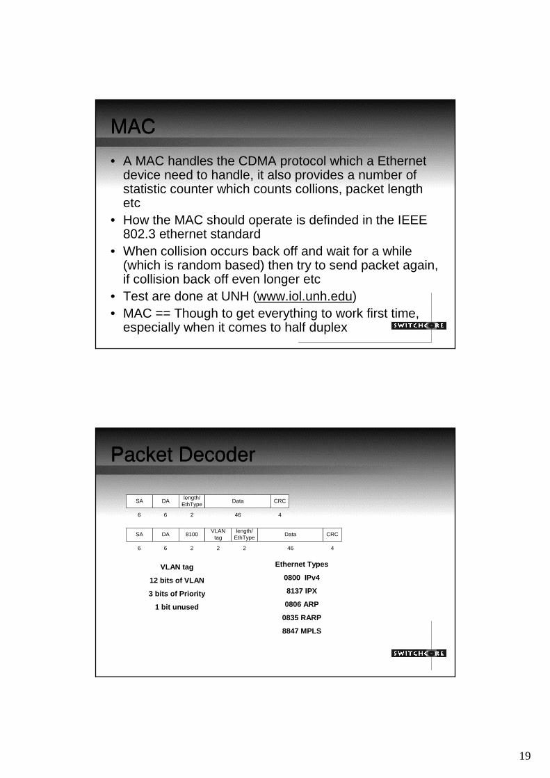
Packet Decoder
SA DAlength/
EthTypeData CRC
6 6 2 46 4
SA DAlength/
EthTypeData CRC
6 6 2 46 4
8100VLAN
tag
22
Ethernet Types
0800 IPv4
8137 IPX
0806 ARP
0835 RARP
8847 MPLS
VLAN tag
12 bits of VLAN
3 bits of Priority
1 bit unused

20
Serial to Parallel
• From a serial input stream builds cells which are stored in the buffer memory
• A state machine visits each entrance cell buffer at a even round robin state
• What is optimal packet size?
Buffer Memory
• How large can a buffer memory actually be?• Can we use external buffers or only on-chip
buffer?• What on-chip buffer choices do we have?
Embedded DRAM, SRAM and 1T SRAM?• What is the clock speed of the buffer memory?• How much area is possible/how large chip are
we building?

21
SRAM types – 1T SRAM
STI
N-well or triple P-well
0 extra mask over CL013 with SRAM0 extra mask over CL025, 018, 015
WL PlateCMOS Cell
STI
well
Poly 3 (gate)
Poly 2 (Cap. plate)
Poly 1 (cap.) SN dielectric
Unit Cell
3 extra masks over CL013
3D Cell
0.25um 6.4mm2/Mb0.18um 3.6mm2/Mb0.15um 2.5mm2/Mb0.13um 1.9mm2/Mb0.10um 0.96-1.15mm2/Mb**
*sizes depend on implementation; for reference only** estimate very preliminary
With redundancy
*
Buffer Memory – going external
• If we want a buffer memory to be very large? Why? – MAN customers count on RTT, try to fix TCP problem
• External buffer memory is slow but it can be a very wide bus
Ingress
Buffer
External Memory DRAM

22
Control Path
PHYCable TP/Optical
MAC Packet Decoder Serial to Parallell
Buffer Memory
Parallel to SerialReencapsulatorMACPHYCable TP/
Optical
Queue Engine
AddressLookup
QoS
Queue Engine
• Inqueue handler which waits for packets to be completed in the Serial to Parallel and that the address lookup unit decides where the packet should be sent. Holds a fifo for each input port.
• After the Inqueue handler has finished it sends a request to theLinker
• Linker links packets into which output port the packet was goingto. Linker also talks to the QoS block which can decide if a packet should be thrown or not.
• When a packet has been linked to a queue the linker tells the scheduler, which in turn selects a packet to be read out
• Linker holds the link memory and Inqueue holds the free instances of the buffer memory

23
Scheduler
Selects packet to be written out from the bufferCan work in many ways:1. Simples possible – Round Robin2. Simples when it comes to priority - Strict Priority3. More advanved WRR – Helps the starvation problem4. CISCO usually wants a two level – divied the queues
into a number of ”sub groups” then have a local scheduler and ”global scheduler”
QoS
A packet will go through a number of QoS features before it is either accepted or thrown
1. Resource Limiter – One port should not take the whole internal memory
2. Classifier which decides which queue the packet should go to
3. Depending on the QoS functions which are needed a packet can also go through a number of ingress and egress token buckets
4. If a packet is not accepted it is linked in the ”throw queue” all packets have to be linked somewhere or the switch will experiance memory leakage

24
Address Lookup
• Decides where a packet should go• A number of different tables which says where the
packer should be sent• Start with VLAN lookup to decide which VLAN a packet
belongs to• Contine with VRP lookup• Contine with L3 lookup • Contine with L2 lookup• Get a bitmaks out saying which ports to link packet into
Lookups?
• How is a lookup done?• Direct addressing• Longest Prefix Match• CAM• Hashing• Address Learing• Aegin

25
Multi Chip Solutions
• Today large Internet routers are usually not one chip solutions• Several chips to solve specific tasks, usually one flow for ingress
and another for the egress• A chip might be for classification and another might be for
address lookup etc.
PHY IP QM
QMEPPHY
Switching Fabric
• Each Queue Manager talks to the Switching fabric• Who gets to send the packet is serveal packets are
competing to send a packet to a specific out port?• Switching fabric needs to be scheduled• Often a switching fabric has a speedup (1.5 – 2.0)• Switching fabric also need to be redundant• Ways to schedule (or arbitrate) a switching fabric can
be done in serveral ways, round robin (leads to 59% throughput), dual round robin, iSlip etc.

26
Switching Fabric
• While some companies are building Network processors others are focusing on the Crossbar
• Standard is the CSIX, founded by Power X• CSIX allows up to 4096 ports and now uses the SPI-4
interface (used to have its own but that proved to be to many pins)
• CSIX is today evolved in the Network Processor Forum (www.npforum.org)
• CSIX is also build to handle up to 256 queues at each output port but it is up the the silicon vendor to decide how many to handle
Network Processor
• Programmability!!!!• How much programmability?• What are you going to use them for?• What is the differance with a normal processor?• Multiple RISC cores or programmable pipeline?

27
Conclusion
• ASIC design is both hard and expensive• ASIC tools are very expensive• Proffit from a successfull ASIC can easily be 1000-
10000 number the amount of money put into the project• Network IC’s will are still in the beginning of their cycle• More and more important for a company (any
company) to be able to use the latest technology to keep its edge agains a compeditor
• A ASIC usually takes about 12 to 18 months to devop depending on the complexity
Related Documents