Ashghal – Traffic Signals Standard Details and Drawing Requirements PWA IAN 017 Rev A1 Page 1 September 2013 ASHGHAL Interim Advice Note No. 017 Traffic Signals Standard Details and Drawing Requirements Revision No. A1 EXW-GENL-0000-PE-KBR-IP-00017 Summary This Interim Advice Note amends the following sections/parts/clauses of the Qatar Highway Standard Details (QHSD) and the Qatar Traffic Manual (QTM) as set out in Attachment A: QHSD SD/6/13/101, SD/6/13/102 and SD/6/13/104 are replaced by Standard Detail Drawing EXW-GENL-0000-PE-KBR-DG-00017-001 Traffic Signal Standard Detail Ducts and Chambers. QHSD SD/6/13/103 is replaced by Standard Detail drawing EXW-GENL-0000-PE-KBR-DG- 00017-001 Traffic Signals Standard Detail Inductive Loop Detection. QTM Marking 523 and Figure 5.4 are replaced by Standard Detail Drawing EXW-GENL-0000- PE-KBR-DG-000017-003 - Traffic Signals Standard Detail Controlled Pedestrian Crossings. This Interim Advice Note shall take precedence over these sections/parts/clauses of the Qatar Highway Standard Details (QHSD) and Qatar Traffic Manual (QTM) QHSD Section 13 QTM Section 5.5.6 This document supersedes IAN 017 Rev 0 dated July 2013. Third parties not working on Ashghal projects make use of this document at their own risk. Paper copies of this document are uncontrolled. Refer to Ashghal’s website for the most recent version. A1 Sept 2013 Issued for All Relevant Infrastructure Projects DL AM AA 0 July 2013 To Provide Direction to Consultants/Contractors CB AM MG Rev Date Reason For Issue Author Chk App

Welcome message from author
This document is posted to help you gain knowledge. Please leave a comment to let me know what you think about it! Share it to your friends and learn new things together.
Transcript
Ashghal – Traffic Signals Standard Details and Drawing Requirements
PWA IAN 017 Rev A1 Page 1 September 2013
ASHGHAL
Interim Advice Note No. 017
Traffic Signals Standard Details and Drawing Requirements
Revision No. A1
EXW-GENL-0000-PE-KBR-IP-00017
Summary
This Interim Advice Note amends the following sections/parts/clauses of the Qatar Highway Standard Details (QHSD) and the Qatar Traffic Manual (QTM) as set out in Attachment A: QHSD SD/6/13/101, SD/6/13/102 and SD/6/13/104 are replaced by Standard Detail Drawing
EXW-GENL-0000-PE-KBR-DG-00017-001 Traffic Signal Standard Detail Ducts and Chambers. QHSD SD/6/13/103 is replaced by Standard Detail drawing EXW-GENL-0000-PE-KBR-DG-
00017-001 Traffic Signals Standard Detail Inductive Loop Detection. QTM Marking 523 and Figure 5.4 are replaced by Standard Detail Drawing EXW-GENL-0000-
PE-KBR-DG-000017-003 - Traffic Signals Standard Detail Controlled Pedestrian Crossings.This Interim Advice Note shall take precedence over these sections/parts/clauses of the Qatar Highway Standard Details (QHSD) and Qatar Traffic Manual (QTM)
QHSD Section 13 QTM Section 5.5.6
This document supersedes IAN 017 Rev 0 dated July 2013. Third parties not working on Ashghalprojects make use of this document at their own risk. Paper copies of this document are uncontrolled. Refer to Ashghal’s website for the most recent version.
A1 Sept 2013 Issued for All Relevant Infrastructure Projects DL AM AA0 July 2013 To Provide Direction to Consultants/Contractors CB AM MG
Rev Date Reason For Issue Author Chk App
Ashghal – Traffic Signals Standard Details and Drawing Requirements
PWA IAN 017 Rev A1 Page 2 September 2013
Contents
1 Foreword ......................................................................................................................3
3 Introduction.................................................................................................................. 5
4 Withdrawn / Amended Standard ................................................................................. 5
5 Additional Standards................................................................................................... 5
6 Implementation ............................................................................................................6
Attachment A - Document No. EXW-GENL-0000-IC-KBR-RP-00017, “Traffic Signal Drawing Standards” ...................................................................................................................................... 7
Ashghal – Traffic Signals Standard Details and Drawing Requirements
PWA IAN 017 Rev A1 Page 3 September 2013
1 Foreword
1.1 Interim Advice Notes (IANs) may be issued by the PMC from time to time. They define specific requirements for works on Expressway projects only, subject to any specific implementation instructions contained within each IAN.
1.2 Whilst IANs shall be read in conjunction with the Standard Documents, and may incorporate amendments or additions to these documents, they are not official updates to the Standard Documents or any other standards.
1.3 The PMC directs which IANs shall be applied to its projects on a case by case basis. Where it is agreed that the guidance contained within a particular IAN is not to be incorporated on a particular project (e.g. physical constraints make implementation prohibitive in terms of land use, cost impact or time delay), a departure from standard shall be applied for by the relevant Consultant / Contractor.
1.4 IANs are generally based on international standards and industry best practice and may include modifications to such standards in order to suit Qatar conditions. Their purpose is to fill gaps in existing Qatar standards where relevant guidance is missing and/or provide higher standards in line with current, international best practice.
1.5 The IANs specify the Expressway Programme requirements in the interim until such time as the current Qatar standards (such as QHDM, QTM, etc.) are updated. These requirements may be incorporated into future updates of the Qatar standards, however this cannot be guaranteed. Therefore, third parties who are not engaged on Expressway projects makeuse of Expressway IANs at their own risk.
1.6 All Expressway IANs are owned, controlled and updated as necessary by the Expressway PMC until adopted and published by ASHGHAL. All technical queries relating to IANs should be directed to the PMC Engineering Manager.
Signed on behalf of Design Department:
____________________________________________________
Abdulla Ahin A A MohdActing Manager of Roads & Drainage Networks Design
Design Management (Roads Section)Public Works Authority
Tel: 44950653Fax: 44950666P.O.Box 22188 Doha - QatarEmail:[email protected]://www.ashghal.gov.qa

Ashghal – Traffic Signals Standard Details and Drawing Requirements
PWA IAN 017 Rev A1 Page 4 September 2013
2. Ashghal Interim Advice Note (IAN) – Feedback Form
Ashghal IANs represent the product of consideration of international standards and best practice against what would work most appropriately for Qatar. However, it is possible that not all issues have been considered, or that there are errors or inconsistencies in an IAN.
If you identify any such issues, it would be appreciated if you could let us know so that amendments can be incorporated into the next revision. Similarly, we would be pleased to receive any general comments you may wish to make. Please use the form below for noting any items that you wish to raise.
Please complete all fields necessary to identify the relevant item
IAN title:
IAN number: Appendix letter:
Page number: Table number:
Paragraph number: Figure number:
Description comment:
Please continue on a separate sheet if required:Your name and contact details (optional):Name: Telephone:
Organisation: Email:Position: Address:
Please email the completed form to:
Abdulla Ahin AA Mohd
Acting Manager of Roads and Drainage Networks DesignDesign Management(Roads Section)Public Works Authority
We cannot acknowledge every response, but we thank you for contributions. Those contributions which bring new issues to our attention will ensure that the IANs will continue to assist in improving quality on Ashghal’s infrastructure projects.

Ashghal – Traffic Signals Standard Details and Drawing Requirements
PWA IAN 017 Rev A1 Page 5 September 2013
3 Introduction3.1 This Interim Advice Note takes immediate effect and shall be read in conjunction with the
Standard Documents and other Ashghal and Expressway Interim Advice Notes (IANs). Specifically:
EBSD/EIS/CADSTD – ASHGHAL CAD Standards Manual EBSD/EIS/GISSTD – ASHGHAL GIS Standards Manual
Expressway Programme documents: EXW-GENL-0000-PE-KBR-IP-00014-001 – Supplement to ASHGHAL CAD & GIS
Standards Manuals and Additional CAD Standards
3.2 This IAN shall apply to Traffic Signal Infrastructure and associated Design Drawings and takes immediate effect.
3.3 This IAN consolidates existing formal and informal design guidance to establish traffic signal drawing standards and standard details. The rational for this IAN is to provide a consistent approach to producing Traffic Signal Plans for the Expressway Program, provide a basis for future schemes to adopt and improve the provision for pedestrians at controlled crossing locations.
4 Withdrawn / Amended Standard4.1 Qatar Highway Standard Details (QHSD) SD/6/13/101, SD/6/13/102 and SD/6/13/104 are
withdrawn.
Standard Detail Drawing EXW-GENL-0000-IC-KBR-DG-00017-001 - Traffic Signal Standard Detail Ducts and Chambers provides minor modifications to the chambers and consolidates thecontent of the above three standards on to single drawing for ease of use.
4.2 QHSD SD/6/13/103 is replaced by Standard Detail drawing EXW-GENL-0000-IC-KBR-DG-00017-003 Traffic Signal Standard Detail Inductive Loop Detection.
4.3 Qatar Traffic Manual (QTM) Marking 523 and Figure 5.4 are withdrawn and replaced by Standard Detail Drawing EXW-GENL-0000-IC-KBR-DG-00017-004 - Traffic Signal Standard Detail Controlled Crossings.
5 Additional Standards5.1 QHSD SD/6/8/108 - Pedestrian Crossings is supplemented by Standard Detail drawing EXW-
GENL-0000-IC-KBR-DG-00017-004 – Traffic Signals Standard Detail Pedestrian Crossings.
5.2 Standard Detail drawing EXW-GENL-0000-IC-KBR-DG-00017-005– Traffic Signal Standard Detail Pedestrian Islands provides:
Pedestrian Island at Traffic Signal Controlled Intersection; Staggered Pedestrian Crossing at Traffic Signal Controlled Intersection;
5.3 Standard Detail drawing EXW-GENL-0000-IC-KBR-DG-00017-006– Traffic Signal Standard Detail Tactile Paving provides Standard Details for:
Tactile Paving Modules and Directional Paving Modules;
5.3 Standard Detail drawing EXW-GENL-0000-IC-KBR-DG-00017-002– Traffic Signal Standard Detail Poles and Heads provides Standard Details for:
Ashghal – Traffic Signals Standard Details and Drawing Requirements
PWA IAN 017 Rev A1 Page 6 September 2013
Traffic Signal Poles; Traffic Signal Heads; Traffic Signal Foundations; Traffic Signal Retention Sockets; and Mast Arm Foundations.
This report provides advice in the context of those features available at the time of writing. The user should check with ASHGHAL on the facilities that are available.
6 Implementation6.1 This IAN shall be implemented with immediate effect on projects as follows:
All Expressway projects in design stage
All Expressway projects in tender stage
6.2 Expressway projects in construction stage shall be reviewed by the Supervision Consultant and Contractor and the implications of adoption of this Interim Advice Note discussed with the respective Expressway Project Manager. This shall include an assessment on the current design to determine whether it complies with this Interim Advice Note and the practicalities of modifying the design and construction in order to achieve compliance.
6.3 The only exceptions are:-
Projects already in construction, where a significant portion of construction and procurement has already occurred and design modification would not be economic or practicable
6.4 If in doubt, Consultants / Contractors should seek guidance from their respective Expressway Project Manager on a project specific basis.
Ashghal – Traffic Signals Standard Details and Drawing Requirements
PWA IAN 017 Rev A1 Page 7 September 2013
Attachment A - Document No. EXW-GENL-0000-IC-KBR-RP-00017, “Traffic Signal Drawing Standards”
Ashghal – Traffic Signals Standard Details and Drawing Requirements
PWA IAN 017 Rev A1 Page R1 September 2013
ASHGHAL
Expressway Programme
Traffic Signal Drawing Standards
Document Number: EXW-GENL-0000-IC-KBR-RP-00017
02 01 July 2013 Issued C. Banfield AM MG01 24 March 2013 Draft C. Banfield AM MG00 01 June 2012 Draft for Internal Circulation C. Banfield FR -
Rev Date Reason For Issue Auth Chk App
Signature Date
Author:
Checked:
Approved:

Ashghal – Traffic Signals Standard Details and Drawing Requirements
PWA IAN 017 Rev A1 Page R2 September 2013
Contents1. Introduction .................................................................................... R3
1.1. Report Objectives............................................................................. R31.2. Associated Standards ...................................................................... R31.3. Withdrawn / Amended Standards..................................................... R31.4. Additional Standards ........................................................................ R3
2. Traffic Signal Plans........................................................................ R52.1. Traffic Signal Layout Plan ................................................................ R6
2.1.1. Traffic Signal Layout ........................................................................ R62.1.2. Ducting Detail................................................................................... R7
2.2. Traffic Signal Detail Plan.................................................................. R82.2.1. Traffic Signal Layout ........................................................................ R82.2.2. Cable Detail Diagram ....................................................................... R92.2.3. Phasing Diagram Chart .................................................................... R92.2.4. Minimum Intergreen Table ............................................................. R102.2.5. Permitted Moves Diagram.............................................................. R112.2.6. Coordinates and Locations............................................................. R11
2.3. General Drawing Requirements ..................................................... R122.3.1. Location Plan ................................................................................. R122.3.2. Drawing Notes................................................................................ R122.3.2.1. Universal Notes.............................................................................. R122.3.2.2. Traffic Signal Layout Plan Notes .................................................... R122.3.2.3. Traffic Signal Detail Plan Notes...................................................... R132.3.3. Traffic Signal Symbols and Blocks ................................................. R132.3.4. Road Markings ............................................................................... R13
3. Standard Details........................................................................... R143.1. Standard Detail Ducts and Chambers............................................ R143.2. Standard Detail Poles and Heads .................................................. R143.3. Standard Detail Detection Equipment ............................................ R153.4. Standard Detail Pedestrian Crossings ........................................... R15
4. References.................................................................................... R16Appendix A - Drawing Content Matrix ............................................................. R17Appendix B - Extract from DfT TAL 01/06 Volume 4....................................... R19Appendix C - Standard Details and Traffic Signal Plans................................ R20
Ashghal – Traffic Signals Standard Details and Drawing Requirements
PWA IAN 017 Rev A1 Page R3 September 2013
1. IntroductionThis document which takes immediate effect consolidates existing formal and informal design guidance to establish a set of traffic signal drawing standards and standard details specifically for projects in ASHGHAL’s Expressway Programme. These formal guidelines may alter ASHGHAL’s previous specifications.
1.1 Report ObjectivesThis report is intended for use by the designers of traffic signal controlled intersections. The rational for this report is to document a consistent approach to producing Traffic Signal Plans for the Expressway Program, provide a basis for future schemes to adopt and improve the provision for pedestrians at controlled crossing locations.
1.2 Associated StandardsThis document should be read in conjunction with the latest version of the following:
ASHGHAL documents: EBSD/EIS/CADSTD – ASHGHAL CAD Standards Manual EBSD/EIS/GISSTD – ASHGHAL GIS Standards Manual
Expressway Programme documents: EXW-GENL-0000-PE-KBR-IP-00014-001 – Supplement to ASHGHAL CAD & GIS
Standards Manuals and Additional CAD Standards
1.3 Withdrawn / Amended StandardsQatar Highway Standard Details (QHSD) SD/6/13/101, SD/6/13/102 and SD/6/13/104 are withdrawn.
Standard Detail Drawing EXW-GENL-0000-PE-KBR-DG-00017-001 - Traffic Signal Standard Detail Ducts and Chambers provides minor modifications to the chambers and consolidates the content of the above three standards on to single drawing for ease of use.
QHSD SD/6/13/103 is replaced by Standard Detail drawing EXW-GENL-0000-PE-KBR-DG-00017-003 Traffic Signals Standard Detail Inductive Loop Detection.
Qatar Traffic Signs Manual (QTSM) Marking 523 and Figure 5.4 are withdrawn and replaced by Standard Detail Drawing EXW-GENL-0000-PE-KBR-DG-00017-004 - Traffic Signals Standard Detail Controlled Pedestrian Crossings.
1.4 Additional StandardsQHSD SD/6/8/108 - Pedestrian Crossings is supplemented by Standard Detail drawing EXW-GENL-0000-PE-KBR-DG-00017-004 – Traffic Signals Standard Detail Controlled Crossings.
Ashghal – Traffic Signals Standard Details and Drawing Requirements
PWA IAN 017 Rev A1 Page R4 September 2013
Standard Detail drawing EXW-GENL-0000-PE-KBR-DG-00017-005 – Traffic Signals Standard Detail Pedestrian Islands provides:
Pedestrian Island at Traffic Signal Controlled Intersection; Staggered Pedestrian Crossing at Traffic Signal Controlled Intersection;
Standard Detail drawing EXW-GENL-0000-PE-KBR-DG-00017-005 – Traffic Signals Standard Detail Tactile Paving provides Standard Details for:
Tactile Paving Modules and Directional Paving Modules;
Standard Detail drawing EXW-GENL-0000-PE-KBR-DG-00017-002 – Traffic Signal Poles and Heads provides Standard Details for:
Traffic Signal Poles; Traffic Signal Heads; Traffic Signal Foundations; and Traffic Signal Retention Sockets;
This report provides advice in the context of those features available at the time of writing. The user should check with ASHGHAL on the facilities that are available.
Ashghal – Traffic Signals Standard Details and Drawing Requirements
PWA IAN 017 Rev A1 Page R5 September 2013
2 Traffic Signal Plans To ensure consistency in Expressway Programme Projects and assist the auditing and review process this report prescribes in detail the requirements for Traffic Signal Plans (TSP) at all stages of the design process, including As Built drawings.
It should be noted that in preparing a traffic signal designs not only is consideration to be given to the information necessary to define the design and the process of auditing drawings but also the requirements of the end user. The end users consist of, but are not limited to:
ASHGALS Roads Operation and Maintenance (use the drawings to establish the traffic signal operational parameters, maintain an accurate record of the site and utilise the data as a reference for maintenance activities).
ASHGHAL EBSD department import the AutoCAD data into ASHGHALS GIS Information and Asset Management system
The Construction Contractor (installs ducts, chambers and signal poles); The Electrical/Traffic Signal Contractor (installs the remainder of the equipment).
For ease of use it is desirable to condense the information on to the minimum number of sheets, whilst maintaining clarity of the information being presented. Therefore:
TSP shall be arranged on two sheets per intersection, consisting of a Traffic Signal Layout Plan and Traffic Signal Detail Plan.
Traffic Signal Layout Plan shall be produced at an engineering scale with civil engineering related information (Intersection Layout and Ducting Detail).
Traffic Signal Detail Plan does not need to be to scale but shall contain electrical and operational details (Phase Diagram, Cable Details, Permitted Moves Diagram etc).
A standardised set of drawing symbols, blocks and line types have been created for use in TSP (Refer to Section 0 1.2 Associated Standards) and the standard notes detailed in section 0shall be utilised for all drawings. Standard notes, should be supplemented by project specific information as necessary.
Standard details for Pedestrian Crossings, Inductive Loops, Ducts and Chambers were previously contained in the Qatar Highway Standard Details. This report consolidates and enhances those elements pertinent to traffic signal design and develops additional standards.
One set of standard details should be appended to a set of TSP for each scheme. The details provided shall include any other project specific standard details necessary for a contractor to complete the installation (or has been used in the installation for As-Built Drawings).
A summary of the drawing requirements is contained in Appendix A - Drawing Content Matrix.
Ashghal – Traffic Signals Standard Details and Drawing Requirements
PWA IAN 017 Rev A1 Page R6 September 2013
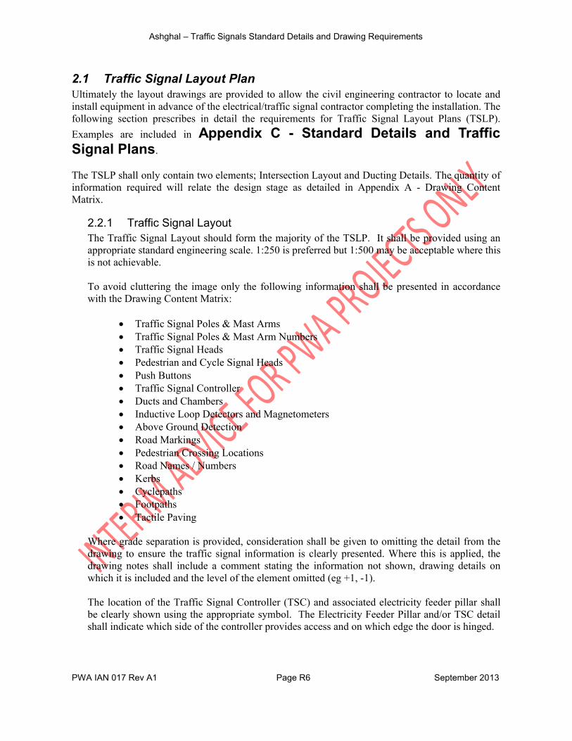
2.1 Traffic Signal Layout PlanUltimately the layout drawings are provided to allow the civil engineering contractor to locate and install equipment in advance of the electrical/traffic signal contractor completing the installation. The following section prescribes in detail the requirements for Traffic Signal Layout Plans (TSLP).
Examples are included in Appendix C - Standard Details and Traffic Signal Plans.
The TSLP shall only contain two elements; Intersection Layout and Ducting Details. The quantity of information required will relate the design stage as detailed in Appendix A - Drawing Content Matrix.
2.2.1 Traffic Signal Layout The Traffic Signal Layout should form the majority of the TSLP. It shall be provided using an appropriate standard engineering scale. 1:250 is preferred but 1:500 may be acceptable where this is not achievable.
To avoid cluttering the image only the following information shall be presented in accordance with the Drawing Content Matrix:
Traffic Signal Poles & Mast Arms Traffic Signal Poles & Mast Arm Numbers Traffic Signal Heads Pedestrian and Cycle Signal Heads Push Buttons Traffic Signal Controller Ducts and Chambers Inductive Loop Detectors and Magnetometers Above Ground Detection Road Markings Pedestrian Crossing Locations Road Names / Numbers Kerbs Cyclepaths Footpaths Tactile Paving
Where grade separation is provided, consideration shall be given to omitting the detail from the drawing to ensure the traffic signal information is clearly presented. Where this is applied, the drawing notes shall include a comment stating the information not shown, drawing details on which it is included and the level of the element omitted (eg +1, -1).
The location of the Traffic Signal Controller (TSC) and associated electricity feeder pillar shall be clearly shown using the appropriate symbol. The Electricity Feeder Pillar and/or TSC detail shall indicate which side of the controller provides access and on which edge the door is hinged.

Ashghal – Traffic Signals Standard Details and Drawing Requirements
PWA IAN 017 Rev A1 Page R7 September 2013
2.1.2 Ducting Detail To allow a civil engineering contractor to complete (or price) all the physical works from just the General Layout Plan it must include the ducting detail, therefore the Ducting Detail shall be included at the Detailed Design or Tender Stage depending on which is earliest.
The Ducting Detail is a schematic layout which presents only information relating to the Chambers, Ducts, Poles and Detector Loops. No Background, Highway or Kerb information is necessary for this schematic.
The drawing shall be orientated to correspond to the Traffic Signal Layout, where this is not possible because of limited space a north point shall be included within the ducting detail frame.
There is no requirement for the ducting detail schematic to be at an engineering scale but the drawing and all labels shall be clearly legible when printed at A3.
All chambers shall be clearly labelled to indicate their type. There are only three types of chambers, refer to Section 0 3.1 Standard Detail Ducts and Chambers.
All ducts shall be clearly labelled to indicate the type and number of ducts. There are only three types of ducts, refer to Section 0 3.1 Standard Detail Ducts and Chambers.
All mast arms and poles shall be clearly numbered. Numbers should start at 1 adjacent to the controller and increment clockwise around the site.
All inductive loop detectors shall be detailed, including the loop tail connection to a Type 3 chamber. Loop numbers shall start at 1 adjacent to the controller and increment clockwise around the site. Magnetometers and associated wireless equipment are not required on the ducting detail
The location of the Traffic Signal Controller (TSC) and associated Electricity Feeder Pillar shall be clearly shown using the appropriate symbol including which side of the cabinets the access door is located and which direction it is hinged.
Note: To avoid cluttering the drawing traffic signal head labels should NOT be included on this
plan (they should be included on the Traffic Signal Detail Plan, refer to Appendix A -Drawing Content Matrix
Ashghal – Traffic Signals Standard Details and Drawing Requirements
PWA IAN 017 Rev A1 Page R8 September 2013
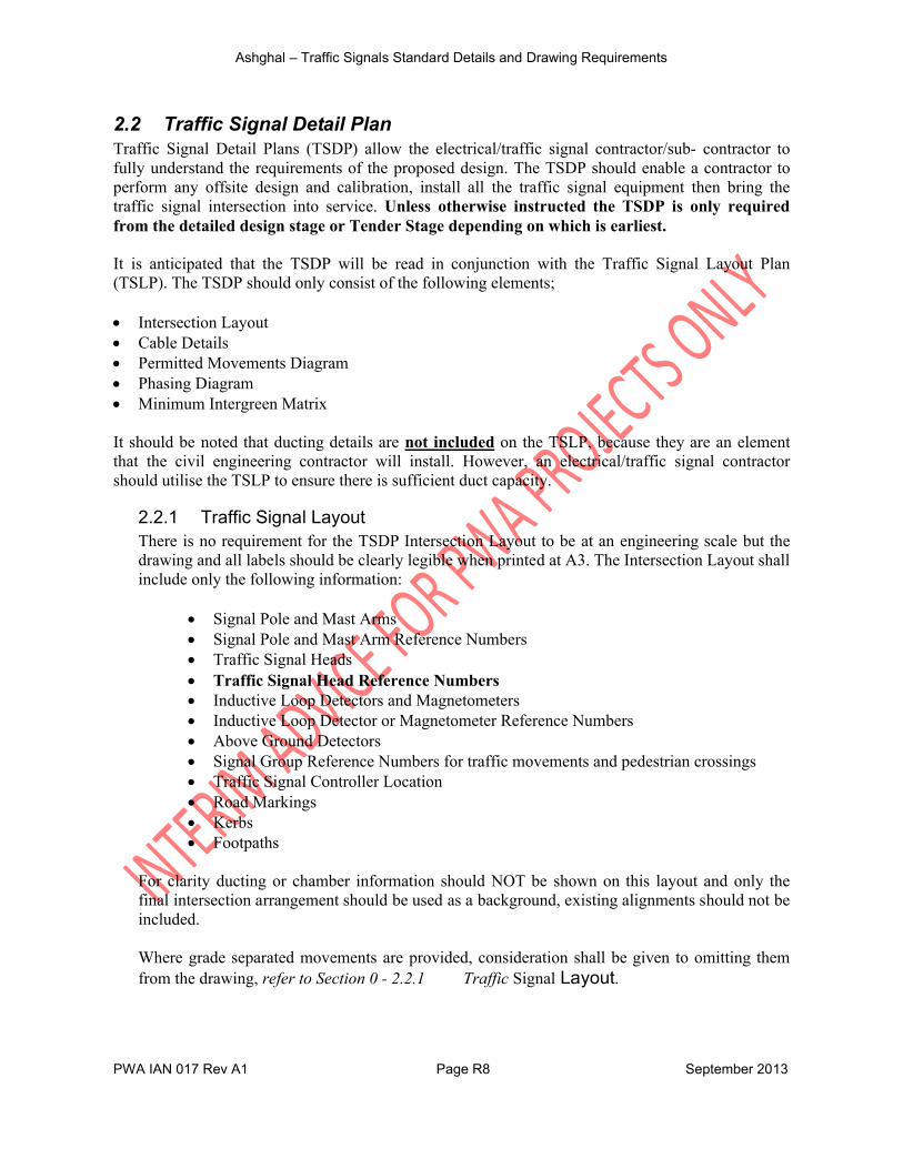
2.2 Traffic Signal Detail PlanTraffic Signal Detail Plans (TSDP) allow the electrical/traffic signal contractor/sub- contractor to fully understand the requirements of the proposed design. The TSDP should enable a contractor to perform any offsite design and calibration, install all the traffic signal equipment then bring the traffic signal intersection into service. Unless otherwise instructed the TSDP is only required from the detailed design stage or Tender Stage depending on which is earliest.
It is anticipated that the TSDP will be read in conjunction with the Traffic Signal Layout Plan (TSLP). The TSDP should only consist of the following elements;
Intersection Layout Cable Details Permitted Movements Diagram Phasing Diagram Minimum Intergreen Matrix
It should be noted that ducting details are not included on the TSLP, because they are an element that the civil engineering contractor will install. However, an electrical/traffic signal contractor should utilise the TSLP to ensure there is sufficient duct capacity.
2.2.1 Traffic Signal LayoutThere is no requirement for the TSDP Intersection Layout to be at an engineering scale but the drawing and all labels should be clearly legible when printed at A3. The Intersection Layout shall include only the following information:
Signal Pole and Mast Arms Signal Pole and Mast Arm Reference Numbers Traffic Signal Heads Traffic Signal Head Reference Numbers Inductive Loop Detectors and Magnetometers Inductive Loop Detector or Magnetometer Reference Numbers Above Ground Detectors Signal Group Reference Numbers for traffic movements and pedestrian crossings Traffic Signal Controller Location Road Markings Kerbs Footpaths
For clarity ducting or chamber information should NOT be shown on this layout and only the final intersection arrangement should be used as a background, existing alignments should not be included.
Where grade separated movements are provided, consideration shall be given to omitting them from the drawing, refer to Section 0 - 2.2.1 Traffic Signal Layout.

Ashghal – Traffic Signals Standard Details and Drawing Requirements
PWA IAN 017 Rev A1 Page R9 September 2013
2.2.2 Cable Detail DiagramTo allow an electrical contractor to complete the installation the TSDP must include cable details. The cable schematic layout is similar to the Ducting Detail but only presents information relating to the TSC, Chambers, Cables and Detector Loops. No Background, Highway or Kerb information is necessary for this schematic.
There is no requirement for the cable detail plan to be at an engineering scale but the drawing and all labels should be clearly legible when printed at A3. The drawing should be orientated to correspond to the TSDP Intersection Layout, where this is not possible because of limited space a north point will be included within the cable detail frame.
All duct runs should be clearly labelled with the Type and Number of cables in each duct ie 2-6P (two 6 pair loop feeder cables) or 2-5C (two 5 core traffic signal cables). Chambers should be included but NOT labelled this information is on the ducting detail.
All mast arms and poles should be clearly labelled with their reference number. Numbers should start adjacent to the controller and increment clockwise around the site.
All traffic signal heads should be labelled using the pole number and a sequential letter for each head on the same mast arm or pole. The reference should be in brackets. Eg (1-A) and located at
the end of the traffic signal arrow head, as shown in Appendix C - Standard Details and Traffic Signal Plans.
All magnetometers and inductive loop detectors should be detailed, including the loop tail connection to a Type 3 chamber. Detector reference numbers should also be included on this plan. Numbers should start at 1 adjacent to the controller and increment clockwise around the site.
The location of the Traffic Signal Controller (TSC) and associated Service Cabinet should be clearly shown and labelled.
2.2.3 Phasing Diagram ChartOne diagram is required that includes all the phases to be configured for all modes of operation. Notes should be included to identify any phases that only operate under specific methods of control.
Arrows should be used to indicate the signal groups which display a green aspect during each phase. Signal groups at red should not be included in the Phasing Diagram. For clarity arrows should utilise straight lines which indicate the direction of travel. The arrow head should be a filled triangle as shown in diagram 4.1.
Curved lines shall only be utilised to represent the circulatory carriageway of signalised roundabouts.
Pedestrian and cycle signal groups should use a Dashed Line to distinguish them from the traffic signal groups and have arrows at both ends.

Ashghal – Traffic Signals Standard Details and Drawing Requirements
PWA IAN 017 Rev A1 Page R10 September 2013
Diagram 4.1 Example Arrows for Phasing Diagrams
In the chart, each arrow shall be associated with its signal group number. Traffic signal group numbers shall be labelled at the beginning of the line (not the arrow head). Pedestrian signal groups should be labelled in the centre and prefixed with a P.
Diagram 2.2 Example Phase Diagram Chart
Each phase shall detail all the traffic signal head reference numbers which display a green signal during the phase, refer to EXW-GENL-0000-PE-KBR-IP-00014-001 Supplement to ASHGHAL CAD & GIS Standards for numbering convention.
2.2.4 Minimum Intergreen TableThe definition of an intergreen is “the period between the end of the steady green signal giving right of way for one signal group, and the beginning of the green signal giving right of way for the next signal group”.
The minimum intergreen is 5 seconds, consisting of 3 second steady amber and a 2 second all red period. Where the distance between conflicting signal groups is large a longer all red period shall be used but it should never be curtailed.
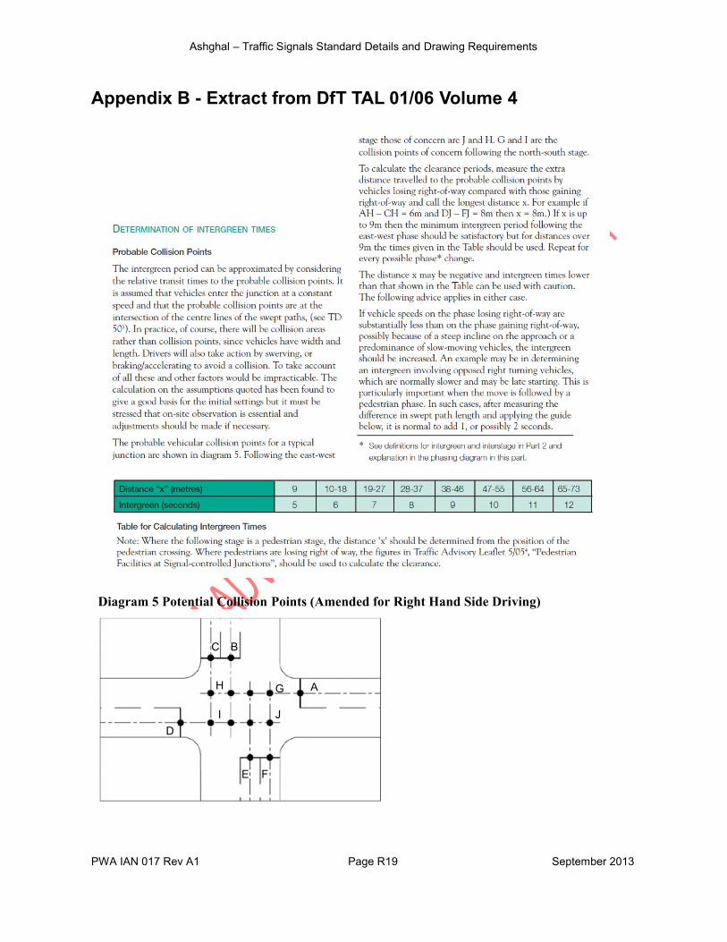
The intergreen period should be calculated for each movement to ensure that appropriate clearance time is provided. The procedure detailed in UK Department for Transport Traffic Advisory Leaflet 01/06 should be used to establish conflict distances. This guidance is contained in Appendix B - Extract from DfT TAL 01/06 Volume 4 but the figure has been updated to reflect driving on the right hand side of the road.
Local practise allows for the inclusion of a 3 second flashing green before the steady amber, this practise is not recommended due to its conflict with the principles of adaptive traffic signal detection. However, if this is proposed it should be added to the intergreen time and clearly stated in the TSDP drawing notes.
1
2
P53
2
3
P6
4
Phase A Phase B Phase C
Green Signal Head States
(1-a) (1-b) (1-c) (1-d)(8-a) (9-a)
Green Signal Head States
(1-a) (1-b) (2-a) (2-b)
Green Signal Head States
(2-a) (2-b) (2-c) (2-d)(6-a) (7-a)
RoundaboutLeft Turn U-Turn PedestrianThrough
Ashghal – Traffic Signals Standard Details and Drawing Requirements
PWA IAN 017 Rev A1 Page R11 September 2013
3
1
2
All Red
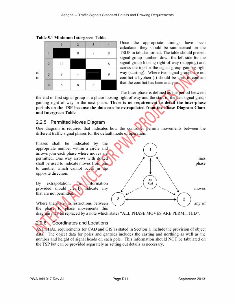
Table 5.1 Minimum Intergreen Table.Once the appropriate timings have been calculated they should be summarised on the TSDP in tabular format. The table should present signal group numbers down the left side for the signal group loosing right of way (stopping) and across the top for the signal group gaining right
of way (starting). Where two signal groups are not in conflict a hyphen (-) should be used to confirm
that the conflict has been analysed.
The Inter-phase is defined as the period between the end of first signal group in a phase loosing right of way and the start of the last signal group gaining right of way in the next phase. There is no requirement to detail the inter-phase periods on the TSP because the data can be extrapolated from the Phase Diagram Chart and Intergreen Table.
2.2.5 Permitted Moves DiagramOne diagram is required that indicates how the controller permits movements between the different traffic signal phases for the default mode of operation.
Phases shall be indicated by the appropriate number within a circle and arrows join each phase where moves are permitted. One way arrows with dotted lines shall be used to indicate moves from one phase to another which cannot occur in the opposite direction.
By extrapolation, the information provided should clearly indicate any moves that are not permitted.
Where there are no restrictions between any of the phase to phase movements this diagram may be replaced by a note which states “ALL PHASE MOVES ARE PERMITTED”.
2.2.6 Coordinates and LocationsASHGHAL requirements for CAD and GIS as stated in Section 1, include the provision of object data. The object data for poles and gantries includes the easting and northing as well as the number and height of signal heads on each pole. This information should NOT be tabulated on the TSP but can be provided separately as setting out details as necessary.
1 2 3 4
1 8 8 8
2 10 - 8
3 8 - 9
4 8 8 8
Ashghal – Traffic Signals Standard Details and Drawing Requirements
PWA IAN 017 Rev A1 Page R12 September 2013
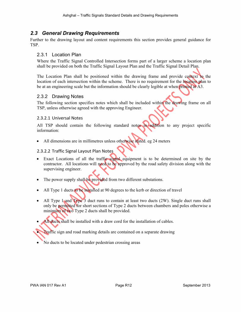
2.3 General Drawing Requirements Further to the drawing layout and content requirements this section provides general guidance for TSP.
2.3.1 Location PlanWhere the Traffic Signal Controlled Intersection forms part of a larger scheme a location plan shall be provided on both the Traffic Signal Layout Plan and the Traffic Signal Detail Plan.
The Location Plan shall be positioned within the drawing frame and provide context to the location of each intersection within the scheme. There is no requirement for the location plan to be at an engineering scale but the information should be clearly legible at when printed at A3.
2.3.2 Drawing NotesThe following section specifies notes which shall be included within the drawing frame on all TSP, unless otherwise agreed with the approving Engineer.
2.3.2.1 Universal NotesAll TSP should contain the following standard notes in addition to any project specific information:
All dimensions are in millimetres unless otherwise stated. eg 24 meters
2.3.2.2 Traffic Signal Layout Plan Notes
Exact Locations of all the traffic signal equipment is to be determined on site by the contractor. All locations will need to be approved by the road safety division along with the supervising engineer.
The power supply shall be provided from two different substations.
All Type 1 ducts to be installed at 90 degrees to the kerb or direction of travel
All Type 1 and Type 3 duct runs to contain at least two ducts (2W). Single duct runs shall only be permitted for short sections of Type 2 ducts between chambers and poles otherwise a minimum of two Type 2 ducts shall be provided.
All ducts shall be installed with a draw cord for the installation of cables.
Traffic sign and road marking details are contained on a separate drawing
No ducts to be located under pedestrian crossing areas

Ashghal – Traffic Signals Standard Details and Drawing Requirements
PWA IAN 017 Rev A1 Page R13 September 2013
2.3.2.3 Traffic Signal Detail Plan Notes The Traffic Signal Controller power supply shall come from two different substations.
Backing boards for all 3 aspect traffic signal heads on gantries shall be louvered or perforated to reduce the stress of wind loading.
2.3.3 Traffic Signal Symbols and BlocksTo ensure consistency between traffic signal layout plans a common set of symbols has been created for the Expressway Programme. These shall be utilised to represent traffic signal and ducting equipment on the TSP.
Symbols, Blocks Line Types, Layer Conventions and Object Properties are defined in document EXW-GENL-0000-PE-KBR-IP-00014-01 – Supplement to ASHGHAL CAD & GIS Standards Manuals and Additional CAD Standards and associated drawings EXW-GENL-0000-PE-KBR-DG-00278-001 onwards.
2.3.4 Road MarkingsSeparate design drawings should be created to detailed road markings. Details of the available road markings and sign types can be found in the Qatar Traffic Manual (QTM). Only those marking pertinent to the traffic signal operation should be included on the layout drawings.

Ashghal – Traffic Signals Standard Details and Drawing Requirements
PWA IAN 017 Rev A1 Page R14 September 2013
3 Standard DetailsIn addition to the layout plans one set of traffic signal standard details should also be produced which cover the entirety of the project. The standard details should be cross referenced in the notes on each of the Traffic Signal Layout Plans and Traffic Signal Detail Plans.
Although standard details already exist in the Qatar Highway Standard Details (QHSD), this report consolidates the elements pertinent to traffic signal designs and provides additional standards relevant to traffic signal controlled intersections.
An electronic copy of the standard details has been attached to this PDF document. These standard details should be appended to each package of Traffic Signal Plans submitted.
3.1 Standard Detail Ducts and ChambersThe standard details for ducts and chambers contained in the QHSD Section 13 have been consolidated on to a single drawing along some with minor updates. Drawing EXW-GENL-
0000-PE-KBR-DG-00017-001 is contained in Appendix C - Standard Details and Traffic Signal Plans. The following elements are covered:
Traffic Signal Chamberso Type 1 – 1200 X 1200 Traffic Signal Controller and High Capacity Chambero Type 2 – 600 X 600 Standard Traffic Signal Chambero Type 3 – 300 X 300 Detection System Chamber
Traffic Signal Ducts o Type 1 – 100mm UPVC for Carriageway Crossingso Type 2 – 100mm UPVC for Block Paved Areas (Footpaths/Medians/Verges)o Type 3 – 50mm UPVC for Detection Systems Only
3.2 Standard Detail Poles and HeadsIt is envisaged that passive safety will be embraced in Qatar and therefore standards have been developed to formalise the production of traffic signal poles, foundations and signal heads which include best practise from around the world. Drawing EXW-GENL-0000-PE-KBR-
DG-00017-002 is contained in Appendix C - Standard Details and Traffic Signal Plans. The following elements are covered:
Traffic Signal Head 300mm (full aspects and arrow aspects) Pedestrian Signal Head Typical Traffic Signal Head Arrangement Signal Pole Foundation Details Retention Socket Foundation Details
Ashghal – Traffic Signals Standard Details and Drawing Requirements
PWA IAN 017 Rev A1 Page R15 September 2013
3.3 Standard Detail Detection Equipment Standard traffic signal detection equipment contained in the QHSD Section 13 has been enhanced by the provision of additional standard details. Drawing EXW-GENL-0000-PE-KBR-
DG-00017-002 is contained in Appendix C - Standard Details and Traffic Signal Plans. The following elements are covered:
Typical Inductive Loop Installation Carriageway to Type 3 Chamber Typical Inductive Loop Configuration Typical Stop Line Inductive Loop Installation Typical Inductive Loop Installation Cable Entry Detail (Inductive Loop Detection)
SCATS is the preferred method of operating traffic signals in Qatar. For SCATS to operate efficiently it is important to feed accurate traffic data, measured at each traffic signal controlled intersection, back to a central server.
To achieve this inductive loops or magnetometers are buried in the carriageway which are used by the system to optimise timings. It is important that inductive loops are of the correct size and orientation for the requirements of SCATS otherwise the traffic data produced will be inaccurate and timings will not be optimal. Default sizes have been provided but the designer should ensure this is appropriate to the application of the loop.
3.4 Standard Detail Pedestrian Crossings The QHSD Section SD/6/13/108, contains a standard detail for Pedestrian Crossings. The arrangement is considered appropriate but the associated dimensions are not suitable for a Traffic Signal Controlled situation where multiple users cross together.
Additional standard details for traffic signal controlled situations are provided in Appendix C - Standard Details and Traffic Signal Plans. These drawings contain the following information:
EXW-GENL-0000-PE-KBR-DG-00017-004 Controlled Crossings Traffic Signal Controlled Pedestrian Crossing; Traffic Signal Controlled Pedestrian Crossing with Tactile Paving; Pedestrian Crossing Markings; Pedestrian Crossing Markings at Traffic Signals; Pole General Arrangement
EXW-GENL-0000-PE-KBR-DG-00017-005 Pedestrian Islands Traffic Island General Arrangement Detail for Uncontrolled Crossings; and Traffic Island General Arrangement Detail for Staggered Pedestrian Crossings.
EXW-GENL-0000-PE-KBR-DG-00017-006 Tactile Paving Tactile Paving Detail Directional Paving Detail
Ashghal – Traffic Signals Standard Details and Drawing Requirements
PWA IAN 017 Rev A1 Page R16 September 2013
4 ReferencesProposed Enhancements To The Functional Road Hierarchy For Qatar (KBR, June 2011)
Qatar Highway Design Manual (Ministry of Municipal Affairs and Agriculture, 1997);
Qatar Traffic Manual, Volume 1 (Ministry of Public Works, )
Qatar Highway Standard Details (Ministry of Municipal Affairs and Agriculture, 2000)
Transport Master Plan For Qatar 1.18-G Pedestrian Facility Guidelines (MMUP, 2008)
Transport Master Plan For Qatar 2.3-R Guide to Planning Roads in Qatar (MMUP, 2008)
Qatar Construction Standards Section 6 Part 13 Traffic Signals (KBR 2010)
Guidance on the use of Tactile Paving (Department For Transport, UK, )
TA 91/05 Provision For Non-Motorised Users (Department For Transport, UK, 2005)
TA 57/87 Roadside Features (Department For Transport, UK, 1987)
TA 86/03 Layout of Large Signal Controlled Intersections (Department For Transport, UK, 2003)
TA 90/05 Geometric Design of Pedestrian, Cycle and Equestrian Routes (Department For Transport, UK, 2005)
TA 91/05 Provision for Non-Motorised Users (Department For Transport, UK, 2005)
TD 22/06 The Layout of Grade Separated Intersections (Department For Transport, UK, 2006)
TD 50/04 The Geometric Layout of Signal Controlled Intersections and Roundabouts (Department For Transport, UK, 2004)
TD 24/97 All-Purpose Trunk Roads Inspection and Maintenance of Traffic Signals and Associated Equipment (Department For Transport, UK, 1997)
TD 18/85 Criteria For The Use Of Gantries And Traffic Signal Matrix Traffic Signals On Trunk Roads And Motorways (Department For Transport, UK, 1985)
LTN 01/95 Assessment of Pedestrian Crossings (Department For Transport, UK, 1995)
LTN 02/95 The Design of Pedestrian Crossings (Department For Transport, UK, 1995)
LTN 01/98 The Installation of Traffic Signals and Associated Equipment (Department For Transport, UK, 1998)
LTN 01/09 Signal Controlled Roundabouts (Department For Transport, UK, 2009)
LTN 02/09 Pedestrian Guard Railing (Department For Transport, UK, 2009)
TAL 04/91 Audible and Tactile Signals at Pelican Crossings (Department For Transport, UK, 1991)
TAL 05/91 Audible and Tactile Signals at Signal Controlled Intersections (Department For Transport, UK, 1991)
TAL 1/06 General Principles of Control by Traffic Signals (Department For Transport, UK, 2006)
TAL 5/05 Pedestrian Facilities at Signal Controlled Intersections (Department For Transport, UK, 2005)
TAL 16/07 General principles of Control by Traffic Signals (Department For Transport, UK, 2007)
Ashghal – Traffic Signals Standard Details and Drawing Requirements
PWA IAN 017 Rev A1 Page R17 September 2013
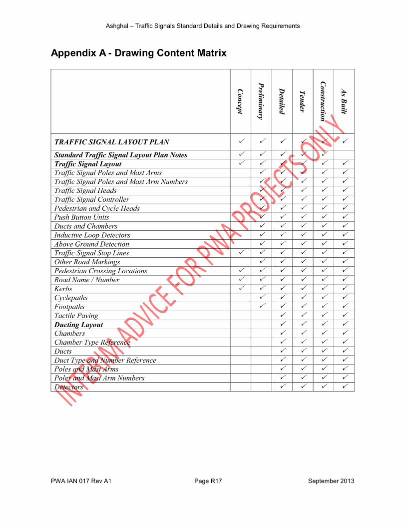
Appendix A - Drawing Content Matrix
Concept
Prelim
inary
Detailed
Tender
Construction
As B
uilt
TRAFFIC SIGNAL LAYOUT PLAN
Standard Traffic Signal Layout Plan Notes Traffic Signal Layout Traffic Signal Poles and Mast Arms Traffic Signal Poles and Mast Arm Numbers Traffic Signal Heads Traffic Signal Controller Pedestrian and Cycle Heads Push Button Units Ducts and Chambers Inductive Loop Detectors Above Ground Detection Traffic Signal Stop Lines Other Road Markings Pedestrian Crossing Locations Road Name / Number Kerbs Cyclepaths Footpaths Tactile Paving Ducting Layout Chambers Chamber Type Reference Ducts Duct Type and Number Reference Poles and Mast Arms Poles and Mast Arm Numbers Detectors
Ashghal – Traffic Signals Standard Details and Drawing Requirements
PWA IAN 017 Rev A1 Page R18 September 2013
Concept
Prelim
inary
Detailed
Tender
Construction
As B
uilt
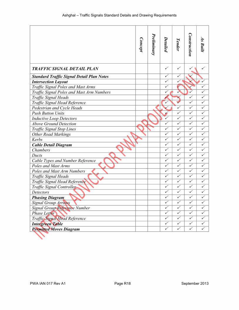
TRAFFIC SIGNAL DETAIL PLAN
Standard Traffic Signal Detail Plan Notes Intersection Layout Traffic Signal Poles and Mast Arms Traffic Signal Poles and Mast Arm Numbers Traffic Signal Heads Traffic Signal Head Reference Pedestrian and Cycle Heads Push Button Units Inductive Loop Detectors Above Ground Detection Traffic Signal Stop Lines Other Road Markings Kerbs Cable Detail Diagram Chambers Ducts Cable Types and Number Reference Poles and Mast Arms Poles and Mast Arm Numbers Traffic Signal Heads Traffic Signal Head Reference Traffic Signal Controller Detectors Phasing Diagram Signal Group Arrows Signal Group Reference Number Phase Letter Traffic Signal Head Reference Intergreen Table Permitted Moves Diagram
Ashghal – Traffic Signals Standard Details and Drawing Requirements
PWA IAN 017 Rev A1 Page R19 September 2013
Appendix B - Extract from DfT TAL 01/06 Volume 4
Diagram 5 Potential Collision Points (Amended for Right Hand Side Driving)
D
BC
A
E F
GH
I J
Ashghal – Traffic Signals Standard Details and Drawing Requirements
PWA IAN 017 Rev A1 Page R20 September 2013
Appendix C - Standard Details and Traffic Signal Plans
EXW-GENL-0000-PE-KBR-DG-00017-001 Traffic Signal Standard Detail Ducts and Chambers
EXW-GENL-0000-PE-KBR-DG-00017-002 Traffic Signal Standard Detail Poles and Heads
EXW-GENL-0000-PE-KBR-DG-00017-003 Traffic Signal Standard Detail Detection Equipment
EXW-GENL-0000-PE-KBR-DG-00017-004 Traffic Signal Standard Detail Controlled Crossings
EXW-GENL-0000-PE-KBR-DG-00017-005 Traffic Signal Standard Detail Pedestrian Islands
EXW-GENL-0000-PE-KBR-DG-00017-006 Traffic Signal Standard Detail Tactile Paving
EXW-GENL-0000-PE-KBR-DG-00017-007 Example Traffic Signal Layout Plans
EXW-GENL-0000-PE-KBR-DG-00017-008 Example Traffic Signal Layout Details
Ashghal – Traffic Signals Standard Details and Drawing Requirements
PWA IAN 017 Rev A1 Page R21 September 2013
Example T-Junction.dwg
Traffic Signals Standard Details Rev 1.dwg
Related Documents