User Manual Advanced Signal Calibrator JOFRA ASC301

Welcome message from author
This document is posted to help you gain knowledge. Please leave a comment to let me know what you think about it! Share it to your friends and learn new things together.
Transcript

User ManualAdvanced Signal Calibrator
JOFRA ASC301

1. Introduction . . . . . . . . . . . . . . . . . . . . . . . . . . . . . . . . . . . . . . . . . . . . . . . . . . .11.1 Contacting Ametek . . . . . . . . . . . . . . . . . . . . . . . . . . . . . . . . . . . . . . . . . . . . . . .11.2 Standard Equipment . . . . . . . . . . . . . . . . . . . . . . . . . . . . . . . . . . . . . . . . . . . . . .11.3 Safety information . . . . . . . . . . . . . . . . . . . . . . . . . . . . . . . . . . . . . . . . . . . . . . . .2
2. Calibrator Interface . . . . . . . . . . . . . . . . . . . . . . . . . . . . . . . . . . . . . . . . . . . . .52.1 Main Display . . . . . . . . . . . . . . . . . . . . . . . . . . . . . . . . . . . . . . . . . . . . . . . . . . .72.2 Menu Bar . . . . . . . . . . . . . . . . . . . . . . . . . . . . . . . . . . . . . . . . . . . . . . . . . . . . . .8
3. Using Measure Modes (Lower Display) . . . . . . . . . . . . . . . . . . . . . . . . . . . .133.1 Measuring volts and frequency . . . . . . . . . . . . . . . . . . . . . . . . . . . . . . . . . . . . .133.2 Measuring mA . . . . . . . . . . . . . . . . . . . . . . . . . . . . . . . . . . . . . . . . . . . . . . . . . .133.3 Measuring Temperature . . . . . . . . . . . . . . . . . . . . . . . . . . . . . . . . . . . . . . . . . . .143.4 Measuring Pressure . . . . . . . . . . . . . . . . . . . . . . . . . . . . . . . . . . . . . . . . . . . . .15
4. Using Source Modes (Lower Display) . . . . . . . . . . . . . . . . . . . . . . . . . . . . .174.1 Setting 0% and 100% Output Parameters . . . . . . . . . . . . . . . . . . . . . . . . . . . . .174.2 Using Auto Output Functions . . . . . . . . . . . . . . . . . . . . . . . . . . . . . . . . . . . . . . .184.3 Sourcing mA . . . . . . . . . . . . . . . . . . . . . . . . . . . . . . . . . . . . . . . . . . . . . . . . . .184.4 Simulating a Transmitter . . . . . . . . . . . . . . . . . . . . . . . . . . . . . . . . . . . . . . . . . .194.5 Sourcing volts . . . . . . . . . . . . . . . . . . . . . . . . . . . . . . . . . . . . . . . . . . . . . . . . . .194.6 Sourcing frequency . . . . . . . . . . . . . . . . . . . . . . . . . . . . . . . . . . . . . . . . . . . . . .194.7 Sourcing a pulse train . . . . . . . . . . . . . . . . . . . . . . . . . . . . . . . . . . . . . . . . . . . .204.8 Sourcing Thermocouples . . . . . . . . . . . . . . . . . . . . . . . . . . . . . . . . . . . . . . . . .214.9 Sourcing Ohms/RTDs . . . . . . . . . . . . . . . . . . . . . . . . . . . . . . . . . . . . . . . . . . . .21
5. Using Isolated Measure Modes (Upper Display) . . . . . . . . . . . . . . . . . . . .235.1 Measuring volts and mA . . . . . . . . . . . . . . . . . . . . . . . . . . . . . . . . . . . . . . . . . .235.2 Measuring current with loop power . . . . . . . . . . . . . . . . . . . . . . . . . . . . . . . . . .235.3 Measuring Pressure . . . . . . . . . . . . . . . . . . . . . . . . . . . . . . . . . . . . . . . . . . . . .24
6. Using the Upper and the Lower Display for Calibration and Testing . . . . .256.1 Performing a Switch Test . . . . . . . . . . . . . . . . . . . . . . . . . . . . . . . . . . . . . . . . .256.2 Testing an Input or Indicating Device . . . . . . . . . . . . . . . . . . . . . . . . . . . . . . . .296.3 Calibrating an I/P Device . . . . . . . . . . . . . . . . . . . . . . . . . . . . . . . . . . . . . . . . . .306.4 Calibrating a Transmitter . . . . . . . . . . . . . . . . . . . . . . . . . . . . . . . . . . . . . . . . . .316.5 Calibrating a Pressure Transmitter . . . . . . . . . . . . . . . . . . . . . . . . . . . . . . . . . . .316.6 Using Scaled Current or Voltage when testing or calibrating a Transmitter. . . . .326.7 Using Percent Error when testing or calibrating a Transmitter. . . . . . . . . . . . . .346.8 Leak Test . . . . . . . . . . . . . . . . . . . . . . . . . . . . . . . . . . . . . . . . . . . . . . . . . . . . .35
7. Remote Operation . . . . . . . . . . . . . . . . . . . . . . . . . . . . . . . . . . . . . . . . . . . . .378. Specifications . . . . . . . . . . . . . . . . . . . . . . . . . . . . . . . . . . . . . . . . . . . . . . . .389. Maintenance . . . . . . . . . . . . . . . . . . . . . . . . . . . . . . . . . . . . . . . . . . . . . . . . .43
9.1 Replacing Batteries . . . . . . . . . . . . . . . . . . . . . . . . . . . . . . . . . . . . . . . . . . . . . .439.2 Cleaning the Unit . . . . . . . . . . . . . . . . . . . . . . . . . . . . . . . . . . . . . . . . . . . . . . .439.3 Service Center Calibration or Repair . . . . . . . . . . . . . . . . . . . . . . . . . . . . . . . .439.4 Replacement Parts & Accessories . . . . . . . . . . . . . . . . . . . . . . . . . . . . . . . . . .44

1
1. Introduction
The AMETEK ASC301 Multifunction Process Calibrator is a handheld, battery-operated instrument that measures and sources electrical and physicalparameters. The calibrator has the following features and functions:
• A dual display. The upper display is used for the measurement of volts,current, pressure, %error, scaling, switch test and pressure leaktest. Thelower display can be used to measure volts, current, pressure, resistancetemperature detectors (RTDs), thermocouples, frequency, and resistance,and to source pulse trains
• A thermocouple (TC) input/output terminal with automatic reference-junctiontemperature compensation.
• An interactive menu
• Complete RS232 interface for remote control
• Isolated read back for transmitter calibration.
• Extended and comprehensive pressure measurement capabilities withJOFRA APM
1.1 Contacting AmetekUS, Canada, Latin America AMETEK TCI at 1-800-527-9999Europe, Africa, Middle East AMETEK Denmark A/S at
+ 45 4816 8000Asia AMETEK Singapore Pte. Ltd. at
+ 65 (64) 842 388
1.2 Standard EquipmentCheck to see if your calibrator is complete. It should include: ASC301 CalibratorInstruction ManualTest LeadsCarrying Case

2
1.3 Safety information
Symbols Used
The following table lists the International Electrical Symbols. Some or all ofthese symbols may be used on the instrument or in this manual.
Symbol Description
AC (Alternating Current)
AC-DC
Battery
CE Complies with European Union Directives
DC
Double Insulated
Electric Shock
Fuse
PE Ground
Hot Surface (Burn Hazard)
Read the User’s Manual (Important Information)
Off
On
Canadian Standards Association
This calibrator must be recycled or disposed of properly (2002/96/EC).

3
The following definitions apply to the terms “Warning” and “Caution”.
• “Warning” identifies conditions and actions that may pose hazards to theuser.
• “Caution” identifies conditions and actions that may damage theinstrument being used.
Use the calibrator only as specified in this manual, otherwise injury anddamage to the calibrator may occur.
WarningThe ASC301 is designed to calibrate and measure low voltage processsignals. To ensure the safety of the operator, DO NOT connect the ASC301to inputs greater than 30 Volts.
WarningTo avoid possible electric shock or personal injury:
• Do not apply more than the rated voltage. See specifications for supportedranges.
• Follow all equipment safety procedures.
• Never touch the probe to a voltage source when the test leads areplugged into the current terminals.
• Do not use the calibrator if it is damaged. Before you use the calibrator,inspect the case. Look for cracks or missing plastic. Pay particularattention to the insulation surrounding the connectors.
• Select the proper function and range for your measurement.
• Make sure the battery cover is closed and latched before you operate thecalibrator.
• Remove test leads from the calibrator before you open the battery door.
• Inspect the test leads for damaged insulation or exposed metal. Checktest leads continuity. Replace damaged test leads before you use thecalibrator.
• When using the probes, keep your fingers away from the probe contacts.Keep your fingers behind the finger guards on the probes.
• Connect the common test lead before you connect the live test lead.When you disconnect test leads, disconnect the live test lead first.
• Do not use the calibrator if it operates abnormally. Protection may beimpaired. When in doubt, have the calibrator serviced.
• Do not operate the calibrator around explosive gas, vapor, or dust.
!
!

• When using a pressure module, make sure the process pressure line isshut off and depressurized before you connect it or disconnect it from thepressure module.
• Disconnect test leads before changing to another measure or sourcefunction.
• When servicing the calibrator, use only specified replacement parts.
• To avoid false readings, which could lead to possible electric shock orpersonal injury, replace the battery as soon as the battery indicatorappears.
• To avoid a violent release of pressure in a pressurized system, shut off thevalve and slowly bleed off the pressure before you attach the pressuremodule to the pressure line.
• To avoid personal injury or damage to the calibrator, use only the specifiedreplacement parts and do not allow water into the case.
CautionTo avoid possible damage to calibrator or to equipment under test:
• Disconnect the power and discharge all high-voltage capacitors beforetesting resistance or continuity.
• Use the proper jacks, function, and range for your measurement orsourcing application.
• If the message changes to "OL" the range limit is exceeded and thepressure source must immediately be removed from the APM to preventdamage to the pressure transducer inside.
• Maximum torque allowed is 13.5 Nm/10 ftlbs. NEVER exceed the torqueallowed.
• To avoid damaging the plastic lens and case, do not use solvents orabrasive cleansers.
Clean the calibrator with a soft cloth dampened with water or water and mildsoap.
4
!

5
2. Calibrator InterfaceFigure 1 shows the location of the input and output connections on thecalibrator, while Table 1 describes their use.
Figure 1. Input/Output Terminals
Table 1: Input and Output Terminals
No. Name Description
1, 2 Measure Isolated V, Input terminals for measuring current, mA terminals voltage, and supplying loop power.
3 TC input/output Terminal for measuring, or simulating ther-mocouples. Accepts miniature polarizedthermocouple plugs with flat in-line bladesspaced 7.9 mm (0.312 in) center to center.
4,5 Source/Measure Terminals for sourcing and measuring V,RTD 2W, Hz, voltage, frequency, pulse train, and RTDs
6,7 Source/Measure Terminals for sourcing and measuring mA terminals, 3W 4W current, and performing RTD measurements
with 3-wire or 4-wire setups.
8 Serial port Connects calibrator to a PC for remote con-trol.
9 Pressure module connector Connects calibrator to a pressure module forpressure measurements.
10 Charger Connector Connector for optional battery charger
F1 F2 F3
CE
1
ENTER
HOME
2 3
4 5 6
7 8 9
- 0 .
+V
mALoop
–
+V
Hz–
Ω3W
mA+
4WmA-
TC
7
8
910
6 53
4
1
2

Figure 2 shows the location of the keys on the calibrator. Table 2 lists thefunctions of each key.
Table 2. Key Functions
No. Name Function
1 Function Keys F1, F2, F3 Used to operate the menu bar at the bottomof the calibrator display. F1 is used forselecting options in the left box, F2 for thecenter box, and F3 for the right box.
2 Arrow Keys Used to adjust output value and for setting 0 and 100% for step and ramp
3 Home Returns to home menu on the menu bar.
4 Power Turns calibrator on and off.
5 Numeric Keypad Allows user to enter Numeric values.
6
F1 F2 F3
CE
1
ENTER
HOME
2 3
4 5 6
7 8 9
- 0 .
1
2
3
5
4
Figure 2. Keypad

7
2.1 Main Display
Figure 3. Display
The display of the calibrator, shown in Figure 3, is divided into three mainsections: the upper display, the lower display, and the menu bar.
The upper display is used for measuring dc voltage, dc current with andwithout loop power, pressure, percent error, scaled value, switch test andleaktest.
The lower display can be used for both measuring and sourcing.
The menu bar is used to setup both the upper and the lower display toperform the desired function.
Table 3 explains the different parts of the display:
Table 3: Display Functions
No. Name Description
1 Primary Parameters Determine what parameter is going to bemeasured or sourced. The available options for the upper displayare:VOLTS IN, PRESSURE, mA IN, SCALED,%ERROR, SW TEST and LEAKTEST.The available options for the lower displayare:VOLTS, TC (thermocouple), RTD, FREQ(frequency), PULSE, PRESSURE, mA, andmA 2W SIM.
2 Input/Output control Switches the lower display between inputmode (read), and output mode (source).
3 Additional Settings Available only for TC (thermocouple), andRTD measurements. For TC this settingturns the CJC (Cold Junction Connection)on and off.For RTD measure [RTD IN], his setting setsthe number of wires used in the measure-ment (2-wire, 3-wire, or 4-wire)
mA IN LOOP
0.000 mA-25.00%
RTD IN 4W P10(90) 385
MENU-OL °C
1
78
4
5
62
3 LIGHT

8
4 Secondary Upper Display Shows where in the preset span the meas-ured value falls. Fixed for mA at 4 (0%) and20 (100%). Also shows mA value for percenterror, mA or Volts value for scaling and timerfor leak test.
5 Units Shows what unit the measurement orsource value is in. Available options are forRTD and TC (°C or °F), and for FREQ andPULSE (CPM, Hz, or KHz)
6 Sensor Types Allow for measurements to be made for dif-ferent types of RTDs and TCs. All types areshown in the Specifications. Also, displaysthe amplitude of the pulse and frequencysource, and pressure units.
7 Numeric Displays Display the numeric values of the signalbeing measured, or sourced. An “OL” read-ing indicates an out of range or overloadcondition.
8 Loop Power Indicator Indicates whether loop power is on or off inmA, Scaled mA and %Error.
2.2 Menu BarThe parameters on the display are controlled by the menu bar, which islocated at the bottom of the LCD. The function keys (F1, F2, and F3) areused to navigate through all the levels and choices of the menu bar. Refer tothe menu tree for a clarification on the layout of all the levels.
The top level of the menu is the home menu. It can be accessed anytime bypressing the HOME key. There are multiple variations of the home menu:the input home menu, the output home menu, the leaktest home menu, andthe pulse home menu.
There are two options for the input home menu. They are MENU andLIGHT. The MENU option is used to enter the main menu. Press thecorresponding function key (F1) to enter the main menu. The LIGHT option(F2) turns the LCD backlight on of off.
In the first output home menu there are three active options, [MENU],[LIGHT] and [STEP or RAMP]. [MENU] and [LIGHT] serve the samepurpose as in the input home menu. STEP or RAMP either steps or rampsthe output.
MENU LIGHT
MENU STEPLIGHT
9
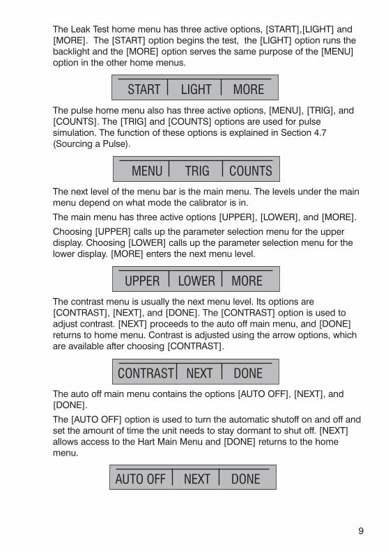
The Leak Test home menu has three active options, [START],[LIGHT] and[MORE]. The [START] option begins the test, the [LIGHT] option runs thebacklight and the [MORE] option serves the same purpose of the [MENU]option in the other home menus.
The pulse home menu also has three active options, [MENU], [TRIG], and[COUNTS]. The [TRIG] and [COUNTS] options are used for pulsesimulation. The function of these options is explained in Section 4.7(Sourcing a Pulse).
The next level of the menu bar is the main menu. The levels under the mainmenu depend on what mode the calibrator is in.
The main menu has three active options [UPPER], [LOWER], and [MORE].
Choosing [UPPER] calls up the parameter selection menu for the upperdisplay. Choosing [LOWER] calls up the parameter selection menu for thelower display. [MORE] enters the next menu level.
The contrast menu is usually the next menu level. Its options are[CONTRAST], [NEXT], and [DONE]. The [CONTRAST] option is used toadjust contrast. [NEXT] proceeds to the auto off main menu, and [DONE]returns to home menu. Contrast is adjusted using the arrow options, whichare available after choosing [CONTRAST].
The auto off main menu contains the options [AUTO OFF], [NEXT], and[DONE].
The [AUTO OFF] option is used to turn the automatic shutoff on and off andset the amount of time the unit needs to stay dormant to shut off. [NEXT]allows access to the Hart Main Menu and [DONE] returns to the homemenu.
START LIGHT MORE

10
The Hart main menu is used to insert a 250Ω resistor into the isolated looppower circuit and the mA source circuit.
The loop power menu is added when mA IN, %ERROR or SCALED mA isselected on the upper display. The [LOOP POWER] option allows access tothe loop power control.
The percent error main menu is added when %ERROR is selected on theupper display. The [%ERROR] option allows access to the percent errorparameters.
The scaling main menu is added when SCALED is selected on the upperdisplay. The [SCALING] option allows access to the parameters used forscaling the value on the upper display.
The leak test timer main menu is added when LEAK TEST is selected on theupper display. The [LT TIMER] option allows access to set the leak testtimer.
When the lower display is in any source mode except pulse mode, the autooutput main menu is added. The options available on this menu are [AUTOFUNC], [NEXT] and [DONE]. The [AUTO FUNC] option allows you to turnthe RAMP/STEP functions on or off. [NEXT] is used to access the contrastmain menu and done returns to the home menu.
AUTO FUNC NEXT DONE
HART NEXT DONE
LOOP POWER NEXT DONE
% ERROR NEXT DONE
SCALING NEXT DONE
LT TIMER NEXT DONE

When the lower display is in the frequency or pulse mode, the frequencylevel menu is added after the auto output main menu. The options availablein this menu are [FREQ LEVEL], [NEXT], and [DONE]. The [FREQ LEVEL]option is used to adjust the amplitude of the wave. [NEXT] is used to accessthe contrast main menu, and [DONE] returns to the home menu.
When the calibrator is in RTD CUSTOM mode, the RTD custom setup menu,is inserted after the main menu. Options [SET CUSTOM], [NEXT], and[DONE] are available. [SET CUSTOM] is used to enter a custom PRT intothe calibrator. Refer to Section 4.9-1 for instructions. [NEXT] is used to enterthe contrast main menu, and [DONE] to return to the home menu.
When pressure is selected on either display the pressure zeroing menu is
inserted after the main menu. It has the options [ZERO ], used to zeropressure, [NEXT] and [DONE], which have the same function as above.Refer to the Section 5.3 for instructions on zeroing.
The parameter selection menu is called up when [UPPER] or [LOWER] isselected from the main menu. It contains the following options: [SELECT],[NEXT], and [DONE]. When the display is selected, a parameter will start toflash. Use the [SELECT] option to change the parameter, and the [NEXT]option to switch to another variable. [DONE] returns to the home menu andenables the selected mode.
11
ZERO NEXT DONE
SELECT NEXT DONE
FREQ LEVEL NEXT DONE
SET CUSTOM NEXT DONE

12
UPPERSelection M
enuLOW
ERM
ORE
SELECTParam
eter SelectionNEXT
DONE
FREQ LEVELFrequency LevelNEXT
DONESET CUSTOMRTD Custom
Menu
If calibrator is inFrequency Outor Pulse m
ode
NEXTDONE
ZEROPressure Zeroing
NEXTDONE
CONTRASTContrast M
enuNEXTDONE
AUTO OFFAuto Off M
enuNEXTDONE If calibrator is in
RTD CUSTOMm
ode
If calibrator is inPressure m
ode
If calibrator is inSource m
odeIf calibrator is inM
easure mode
AUTO FUNCAuto Output M
ain Menu
NEXTDONE
%ERROR
Percent ErrorNEXT
DONE
If calibrator is inPercent Errorm
ode
SCALINGScaling M
ain Menu
NEXTDONE
If calibrator is inScale Inputm
ode
LT TIMER
Leaktest TimerNEXT
DONE
If calibrator is inLeaktest m
ode
HARTHart M
ain MenuNEXT
DONE
MENU
Home M
enuLIGHT
MENU
Home M
enuLIGHT
MENU
Home M
enuLIGHTM
ENUHom
e MenuLIGHT
MENU
Home M
enuLIGHTM
ENUHom
e MenuLIGHT
MENU
Home M
enuLIGHT
MENU
Home M
enuLIGHT
MENU
Home M
enuLIGHT
MENU
Home M
enuLIGHT
MENU
Home M
enuLIGHT
Figu
re 4. Sim
plified
Men
u Tree

13
3. Using Measure Modes (Lower Display)
3.1 Measuring volts and frequencyElectrical parameters volts and frequency can be measured using the lowerdisplay. To make the desired measurements, follow these steps:
1. Switch to the lower display [LOWER] from Main Menu.
2. Select the desired parameter for measurement.
3. Connect leads as shown in Figure 5.
Figure 5. Measuring Volts and Frequency with Input/Output Terminals
3.2 Measuring mATo measure mA follow these steps:
1. Switch to lower display and select mA.
2. Make sure the input/output control is set to IN.
3. Connect leads as shown in Figure 6.
Figure 6. Measuring mA with Input/Output Terminals
VOLTS IN
-0.000 VVOLTS IN
MENU5.000 V
LIGHT
+V
mALoop
–
+V
Hz–
Ω
3WmA+
4WmA-
TC
–
+
+V
mALoop
–
+V
Hz–
Ω
3WmA+
4WmA-
TC–
+
mA IN
0.000 mA-25.00%
mA IN
MENU5.000 mA
LIGHT

14
3.3 Measuring Temperature
3.3-1 Using Thermocouples
The calibrator supports the followingthermocouple types: B, C, E, J, K, L,N, R, S, T, U, BP, and XK. Thecharacteristics of all the types aredescribed in Specifications section.The calibrator also has a ColdJunction Compensation (CJC)function. Normally this function should be ON and the actual temperature ofthe thermocouple will be measured. With CJC OFF, the calibrator willmeasure the difference between the thermocouple at the junction and at itsTC input terminal.
Note: CJC off mode should only be used when calibration is being doneusing an external ice bath.
To use the thermocouple to measure temperature, follow these steps:
1. Attach the thermocouple leads to the TC miniplug, and insert the pluginto the input/output of the calibrator, as in Figure 7.
Note: For best accuracy wait 2 to 5 minutes for the temperature betweenthe miniplug and the calibrator to stabilize before any measurements aretaken.
2. Switch to lower display from Main Menu.
3. Select TC from the primary parameters. Choose [IN] in the input/outputcontrol, and than the thermocouple type from the sensor types. Thetemperature unit may also be changed from Celsius to Fahrenheit.
The calibrator can also measure the mV of a Thermocouple, which can beused along with a table in case the corresponding TC type is not supportedby the calibrator. To do so, proceed as above and choose mV from sensortypes.
Figure 7. Measuring Temperature Using Thermocouple Terminals
mA IN
0.000 mA-25.00%
TC IN CJC OFF B
MENUOL °C
LIGHT
+V
mALoop
–
+V
Hz–
Ω
3WmA+
4WmA-
TC
+–
TC PLUG Note: The TC wireused must match thethermocouple typebeing calibrated.

15
3.3-2 Using Resistance-Temperature-Detectors (RTDs)
The supported types of RTDs are shown in Section 8. Specifications.RTDs are characterized by their 0°C resistance, R0. The calibratoraccepts two, three, and four wire inputs, with four wire input being themost accurate.
To use the RTD option, apply the following steps:
1. Switch to lower display [LOWER] from Main Menu.
2. Select RTD from the primary parameters. Select [IN] frominput/output control.
3. Choose 2, 3, or 4-wire connection [2W, 3W, 4W]. (4-wire allows forthe most precise measurement)
4. Select RTD type from the sensor types.
5. Attach RTD leads as shown in Figure 8.
Figure 8. Measuring Temperature with RTD Connection
Resistance can also be measured using this function. To do so, use theabove procedure and choose OHMS from the sensor types. This optioncan be used along with a table to measure an RTD which is notprogrammed into the calibrator.
3.4 Measuring Pressure
Warning!To avoid a violent release of pressure in a pressurized system, shut off thevalve and slowly bleed off the pressure before you attach the pressuremodule to the pressure line.
+V
mALoop
–
+V
Hz–
Ω
3WmA+
4WmA-
TC
–
+
–
+
–
+
–
+
–
+
–
+
RTD2W
3W
4W
RTD
RTD
mA IN
0.000 mA-25.00%
RTD IN 4W P10(90) 385
MENU25.0 °C
LIGHT
!

16
CautionTo avoid mechanically damaging the pressure module, never apply more than13.5 Nm/10 ftlbs. of torque between the pressure module fittings, or betweenthe fittings an the body of the module.
To avoid damaging the pressure module from overpressure, never applypressure above the rated maximum printed on the module.
To avoid damaging the pressure module from corrosion, use it only withspecified materials. Refer to the pressure module documentation for materialcompatibility.
To measure pressure, follow these steps:
1. Connect the pressure module to the calibrator as shown in Figure 9.
The calibrator can measure pressure on both the upper and the lowerdisplay. This makes it possible to measure pressure in two different unitsat the same time.
2. Switch to either upper or lower display from the Main Menu.
3. Select [PRESSURE] from the primary parameters.
4. Select the desired measuring unit.
5. Zero the pressure module. The zero function on the calibrator can befound in the pressure zeroing menu.
Figure 9. Connections for Measuring Pressure
3.4-1 Zeroing with Absolute Pressure Modules.
To zero, adjust the calibrator to read a known pressure, such as barometricpressure.
To adjust the calibrator, follow these steps:
PRESSUREMODULE
VALVE
F1 F2 F3
CE
1
ENTER
HOME
2 3
4 5 6
7 8 9
- 0 .
!
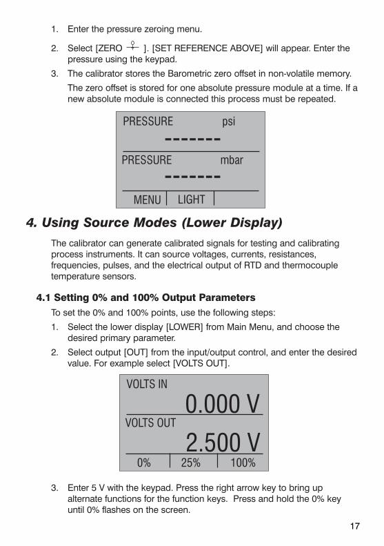
1. Enter the pressure zeroing menu.
2. Select [ZERO ]. [SET REFERENCE ABOVE] will appear. Enter thepressure using the keypad.
3. The calibrator stores the Barometric zero offset in non-volatile memory.
The zero offset is stored for one absolute pressure module at a time. If anew absolute module is connected this process must be repeated.
4. Using Source Modes (Lower Display)The calibrator can generate calibrated signals for testing and calibratingprocess instruments. It can source voltages, currents, resistances,frequencies, pulses, and the electrical output of RTD and thermocoupletemperature sensors.
4.1 Setting 0% and 100% Output Parameters To set the 0% and 100% points, use the following steps:
1. Select the lower display [LOWER] from Main Menu, and choose thedesired primary parameter.
2. Select output [OUT] from the input/output control, and enter the desiredvalue. For example select [VOLTS OUT].
3. Enter 5 V with the keypad. Press the right arrow key to bring upalternate functions for the function keys. Press and hold the 0% keyuntil 0% flashes on the screen.
17
PRESSURE
-------psi
PRESSURE mbar
MENU
-------LIGHT
VOLTS IN
0.000 VVOLTS OUT
0%2.500 V
25% 100%

18
4. Enter 20 V with the keypad. Press the right arrow key to bring upalternate functions for the function keys. Press and hold the 100% keyuntil 100% flashes on the screen.
5. Use the F2 key to cycle 5 V and 20 V in either 10% or 25% increments,depending on which is selected.
4.1-1 Manually stepping the current output
To use the 25% function with mA output, follow these steps:
1. Select the lower display from the Main Menu, and choose mA.
2. Use the 25% key to cycle between 4 mA and 20 mA in 25% intervals.
Note: You can also configure the unit to output in 10% steps.
4.2 Using Auto Output FunctionsThere are two Auto Output functions; [STEP] and [RAMP]. When the [STEP]function is selected the calibrator steps from the 0% set source value to the100% set source value in 10% or 25% increments. The word [STEP] turns to[STEPPING] when the [STEP] function is active. The [RAMP] function rampsthe calibrator output from the 0% to 100% set source values. When the[RAMP] function is active the word [RAMP] turns to [RAMPING]. Both the[STEP] and [RAMP] functions will continue from 0% to 100% and backagain until a key is pressed.
Note: Auto Output options are not available for the Pulse Output function.
4.3 Sourcing mA To source a current, follow these steps:
1. From the Main Menu select lower display [LOWER]. Choose [mA] fromthe primary parameters.
2. Switch to input/output control, and select output [OUT].
3. Connect the leads to the mA terminals, as shown in Figure 10.
4. Enter the desired current using the keypad.
Figure 10. Connections for Sourcing Current
mA IN LOOP
0.000 mA-25.00 %
mA OUT
MENU5.000 mA
LIGHT
+V
mALoop
–
+V
Hz–
Ω
3WmA+
4WmA-
TC
–
+
1000 ohms max.
UUT

19
4.4 Simulating a TransmitterTo have the calibrator supply a variable test current to a loop in place of atransmitter, follow these steps:
1. Select lower display from the Main Menu.
2. Choose mA simulation from the primary parameters [mA 2W SIM], andenter the desired current.
3. Connect the 24V loop as shown in Figure 11.
Figure 11. Connections for Simulating a Transmitter
4.5 Sourcing voltsTo source volts follow these steps:
1. Select lower display from the Main Menu.
2. Choose [VOLTS] from the primary parameters. Switch to input/outputcontrol and select output [OUT].
3. Connect the leads for the voltage source terminals, as shown in Figure 12.
4. Enter the voltage using the keypad.
Figure 12. Connections for Sourcing Voltage and Frequency
4.6 Sourcing frequencyTo source a signal use these steps:
1. Switch to the lower display and select frequency from the primaryparameters.
+V
mALoop
–
+V
Hz–
Ω
3WmA+
4WmA-
TC
–
–
+
+LOOPPOWERSUPPLY
30 VDCMAX
UUT
+V
mALoop
–
+V
Hz–
Ω
3WmA+
4WmA-
TC
–
+
UUT
mA IN LOOP
0.000 mA-25.00%
VOLTS OUT
MENU6.000 V
LIGHT
mA IN LOOP
0.000 mA-25.00%
mA 2W SIM
MENU4.000 mA
LIGHT

20
2. Select output, and than choose the frequency units.
3. Connect the leads to the frequency output terminals as shown in Figure 12.
4. Enter the desired frequency using the keypad.
5. To change the amplitude, select [FREQ LEVEL] from frequency level menu.
6. Enter the amplitude.
4.7 Sourcing a pulse trainThe calibrator can produce a pulse train with an adjustable number of pulsesat a desired frequency. For example, setting the frequency to 60Hz and thenumber of pulses to 60 would produce 60 pulses for a period of 1 second. Tosource a pulse, use the same connection as for frequency, and proceed asfollows:
1. Switch to the lower display and select pulse from the primary parameters.
2. Choose the desired unit and enter the frequency using the keypad.
3. Select the [COUNTS] function from the home menu to enter the numberof pulses. Use [TRIG] to start and stop the signal.
4. The amplitude of the pulse can be adjusted in the same manner as forfrequency.
Figure 13. Connections for Outputting Thermocouples
+V
mALoop
–
+V
Hz–
Ω
3WmA+
4WmA-
TC–+
+–
TC PLUGNote: TC wire used must matchthe thermocouple type being calibrated.
mA IN LOOP
0.000 mA-25.00%
PULSE 5.0 Vpp
MENU5.0 kHzTRIG COUNTS
mA IN LOOP
0.000 mA-25.00%
FREQ OUT 5.0 Vpp
MENU4.0 kHz
LIGHT

21
4.8 Sourcing ThermocouplesTo source a thermocouple use the following steps:
1. Connect the thermocouple leads to the appropriate polarized TCminiplug, and insert the plug into the TC terminals on the calibrator, asshown in Figure 13.
2. Select lower display from the Main Menu, and choose thermocouple[TC] from the primary parameters.
3. Choose output [OUT] from the input/output control.
4. Select the desired thermocouple type from the sensor types.
5. Enter the temperature using the keypad.
Figure 14. Connections for Outputting RTDs
4.9 Sourcing Ohms/RTDsTo source an RTD, follow these steps:
1. Select lower display from the Main Menu, and choose [RTD] from theprimary parameters.
2. Choose output [OUT] from the input/output control, and select RTDtype from the sensor types.
3. Connect the calibrator to the instrument being tested, as in Figure 14.
4. Enter the temperature or resistance using the keypad.
mA IN
0.000 mA-25.00%
TC OUT CJC OFF E
MENU100.0 °C
LIGHT
+V
mALoop
–
+V
Hz–
Ω
3WmA+
4WmA-
TC

22
Figure 15. Using a 3- or 4-wire Connection for RTDs
Note: The calibrator simulates a 2-wire RTD. To connect 3- or 4-wiretransmitter, use stacking cables, as shown in Figure 15.
4.9-1 Custom RTD
A custom curve-fit PRT may be entered into the calibrator for sourcingand measuring. To do so follow these steps:
1. Switch to lower display. Select RTD and set sensor type toCUSTOM.
2. Enter the RTD custom setup main menu, and select [SETCUSTOM].
3. Using the keypad, enter the values that the calibrator prompts for:minimum temperature, maximum temperature, R0, and the valuesfor each of the temperature coefficients.
–
+
–
+
–
+
–
+
–
+
–
+
3W 4W
1 1
2 2
3 3
4 4
Use stackabletest leads for
shared connections
mA IN LOOP
0.000 mA-25.00%
RTD OUT P500(90)385
MENU10.0 °CLIGHT

The custom function uses the Calendar-Van Dusen equation foroutputting and measuring custom RTDs. The coefficient C is only usedfor temperatures below 0°C. Only A and B coefficients are needed forthe range above 0°C, so coefficient C should be set to 0. The R0 is theresistance of the probe at 0°C. The ITS 90 coefficients for PT385,PT3926, and PT3616 are shown in Table 4.
Table 4. RTD Coefficients
RTD Range(°C) R0 Coefficient A Coefficient B Coefficient C
PT385 -260 - 0 100 3.9083x10⁻³ -5.775x10⁻⁷ -4.183x10⁻¹²
PT385 0 - 630 100 3.9083x10⁻³ -5.775x10⁻⁷ ---
PT3926 Below 0 100 3.9848x10⁻³ -5.87x10⁻⁷ -4x10-12
PT3926 Above 0 100 3.9848x10⁻³ -5.87x10⁻⁷ ---
PT3916 Below 0 100 3.9692x10⁻³ -5.8495x10⁻⁷ -4.2325x10⁻¹²
PT3916 Above 0 100 3.9692x10⁻³ -5.8495x10⁻⁷ ---
5. Using Isolated Measure Modes (Upper Display)
5.1 Measuring volts and mAUse the following steps to measure the voltage or current output of atransmitter.
1. Select the upper display from the Main Menu.
2. Select the desired primary parameter to be measured. Connect theleads to the isolated inputs of the calibrator, as in Figure 16.
Figure 16. Isolated Input Connection
5.2 Measuring current with loop powerTo test a 2-wire, loop powered transmitter that is disconnected from wiring,use the loop power function. This function activates a 24V supply in serieswith the current measuring circuit. To use this option proceed as follows:
23
+V
mALoop
–
+V
Hz–
Ω
3WmA+
4WmA-
TC
–
+

1. Select [mA] as primary parameter in the upper display.
2. Use the menu to turn on loop power. Connect the calibrator totransmitter current loop terminals, as shown in Figure 17.
Figure 17. Connection Using Current Loop
5.3 Measuring Pressure
Warning!To avoid a violent release of pressure in a pressurized system, shut off thevalve and slowly bleed off the pressure before you attach the pressuremodule to the pressure line.
CautionTo avoid mechanically damaging the pressure module, never apply morethan 13.5 Nm/10 ftlbs. of torque between the pressure module fittings, orbetween the fittings an the body of the module.
To avoid damaging the pressure module from overpressure, never applypressure above the rated maximum printed on the module.
To avoid damaging the pressure module from corrosion, use it only withspecified materials. Refer to the pressure module documentation formaterial compatibility.
24
+V
mALoop
–
+V
Hz–
Ω
3WmA+
4WmA-
TC
–+
!
!
mA IN LOOP
0.000 mA-25.00%
mA IN
MENU-0.001 mA
LIGHT

To measure pressure, follow these steps:
1. Connect the pressure module to the calibrator as shown in Figure 18.
The calibrator can measure pressure on both the upper and the lowerdisplay. This makes it possible to measure pressure in two different unitsat the same time.
2. Switch to either upper or lower display from the Main Menu.
3. Select [PRESSURE] from the primary parameters.
4. Select the desired measuring unit.
5. Zero the pressure module. The zero function on the calibrator can befound in the pressure zeroing menu. For zeroing absolute modules see3.4.1.
Figure 18. Measuring Pressure Transmitter
6. Using the Upper and the Lower Display forCalibration and Testing
6.1 Performing a Switch TestThe calibrator can stimulate a switch and capture the results in anysource/simulate mode (except pulse) and the calibrator can also monitor aswitch and capture the results in any read mode based on the inputrequirements of the switch. Examples are given below for a temperatureswitch with an external temperature source and a pressure switch.
25
PRESSUREMODULE
VALVE
F1 F2 F3
CE
1
ENTER
HOME
2 3
4 5 6
7 8 9
- 0 .

26
6.1.1 Performing a Temperature Switch Test:
Figure 19. Temperature Switch Test
1. Use the menu to select SW TEST on the upper display.
2. Connect the calibrator to the switch using the switch terminals. Thepolarity of the terminals does not matter.
3. The top of the display will read “CLOSE”.
4. Raise the temperature slowly until the switch opens.
5. Once the switch is open, “OPEN” will be displayed, lower the temperatureslowly until the switch closes.
P100-385
SW TEST CLOSE
RTD IN 4W
100.0 °C
------ °C
MENU LIGHT
RTD Probe
TemperatureSwitch
+V
mALoop
–
+V
Hz–
Ω
3WmA+
4WmA-
TC
27
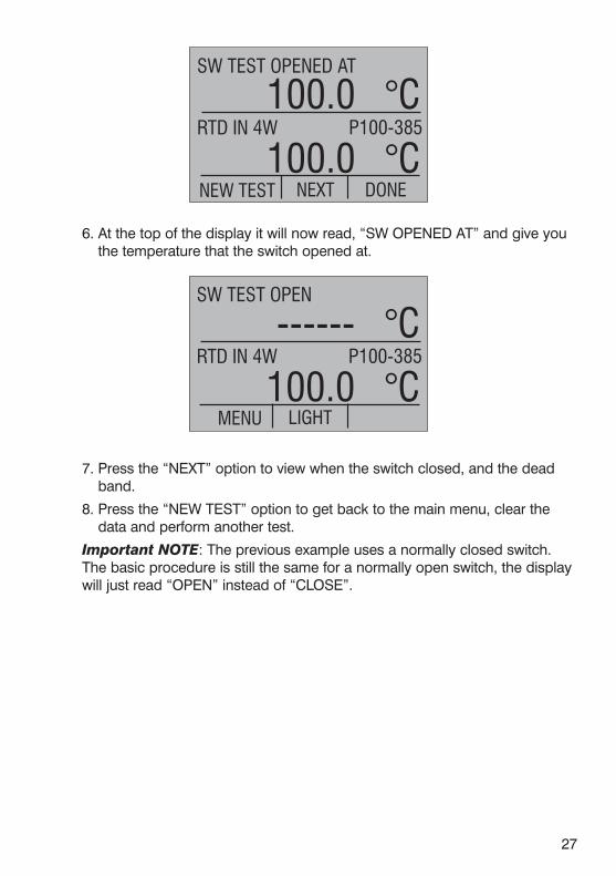
6. At the top of the display it will now read, “SW OPENED AT” and give youthe temperature that the switch opened at.
7. Press the “NEXT” option to view when the switch closed, and the deadband.
8. Press the “NEW TEST” option to get back to the main menu, clear thedata and perform another test.
Important NOTE: The previous example uses a normally closed switch.The basic procedure is still the same for a normally open switch, the displaywill just read “OPEN” instead of “CLOSE”.
P100-385
SW TEST OPEN
RTD IN 4W
MENU100.0 °C
LIGHT
------ °C
P100-385
SW TEST OPENED AT
RTD IN 4W
NEW TEST100.0 °C
NEXT
100.0 °C
DONE

28
6.1.2 Performing a pressure switch test:
Figure 20. Pressure Switch Test
1. Use the menu to select SW TEST on the upper display.
2. Connect the calibrator to the switch using the pressure switch terminals.The polarity of the terminals does not matter. Then connect the pump tothe calibrator and the pressure switch.
3. Make sure the vent on the pump is open. Zero the calibrator if necessary.Close vent after zeroing the calibrator.
4. The top of the display will read “CLOSE”.
5. Apply pressure with the pump slowly until the switch opens.
Important NOTE: In the switch test mode the display update rate isincreased to help capture changing pressure inputs. Even with this
psi
SW TEST CLOSE
MENU0.000
LIGHT
------ psi
HAND PUMP
PRESSUREMODULE
PressureSwitch F1 F2 F3
CE
1
ENTER
HOME
2 3
4 5 6
7 8 9
- 0 .

29
enhanced sample rate pressurizing device under test should be done slowlyto ensure accurate readings.
6. Once the switch is open, “OPEN” will be displayed, bleed the pumpslowly until the pressure switch closes.
7. At the top of the display it will now read, “SW OPENED AT” and give youthe pressure that the switch opened at.
8. Press the “NEXT” option to view when the switch closed, and the deadband.
Important NOTE: The previous example uses a normally closed switch.The basic procedure is still the same for a normally open switch, the displaywill just read “OPEN” instead of “CLOSE”.
6.2 Testing an Input or Indicating DeviceTo test and calibrate actuators, recording, and indicating devices using thesource functions, follow these steps:
1. Select the lower display and choose the correct primary parameter.
2. Switch to [OUT] in the input/output control.
3. Connect the leads to the instrument and the calibrator as shown inFigure 21.
psi
SW OPENED AT
MENU28.000
LIGHT
30.000 psi
psi
SW TEST OPEN
MENU28.000
LIGHT
------ psi
30
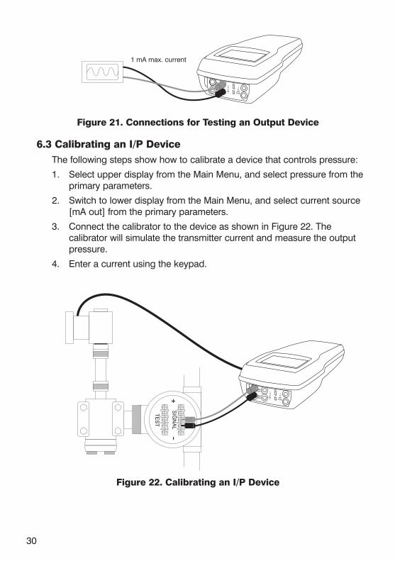
Figure 21. Connections for Testing an Output Device
6.3 Calibrating an I/P DeviceThe following steps show how to calibrate a device that controls pressure:
1. Select upper display from the Main Menu, and select pressure from theprimary parameters.
2. Switch to lower display from the Main Menu, and select current source[mA out] from the primary parameters.
3. Connect the calibrator to the device as shown in Figure 22. Thecalibrator will simulate the transmitter current and measure the outputpressure.
4. Enter a current using the keypad.
Figure 22. Calibrating an I/P Device
+V
mALoop
–
+V
Hz–
Ω
3WmA+
4WmA-
TC
–+
SIG
NA
L
TES
T
+V
mALoop
–
+V
Hz–
Ω
3WmA+
4WmA-
TC
1 mA max. current

31
6.4 Calibrating a Transmitter To calibrate a transmitter both the upper and the lower displays will be used;one for measuring and the second a source. This section covers all but thepressure transmitters. A thermocouple temperature transmitter is used in thisexample.
The following steps show how to calibrate a temperature transmitter:
1. From the Main Menu select upper display, and choose current loop[mA]. Use the LOOP POWER menu to turn loop power on.
2. Switch to lower display from the Main Menu, and select [TC] from theprimary parameters. Choose output [OUT] from the input/output control,and select TC type.
3. Set the 0% and 100% span points using the keypad and the 0% and100% keys (refer to Setting 0% and 100% Parameters section).
4. Connect the calibrator to the transmitter as shown in Figure 21.
5. Test transmitter at 0- 25- 50- 75- 100% using the 25% step function.
Adjust the transmitter as necessary.
To calibrate a different transmitter, follow the above steps with the exceptionof choosing TC on the lower display. Replace TC with the correct parameterfor the transmitter.
Figure 23. Calibrating a Transmitter
6.5 Calibrating a Pressure TransmitterTo calibrate a pressure transmitter, use these steps:
1. Select upper display from the Main Menu, and choose current [mALOOP] from the primary parameters. Return to Main Menu.
2. Select lower display, and choose [PRESSURE] from the primaryparameters.
3. Connect the calibrator to the transmitter and the pressure module as inFigure 24.
4. Zero the pressure module.
+V
mALoop
–
+V
Hz–
Ω
3WmA+
4WmA-
TC

32
5. Test the transmitter at 0% and 100% of the span, and adjust asnecessary.
Figure 24. Calibrating a Pressure Transmitter
6.6 Using Scaled Current or Voltage when testing or calibratinga Transmitter.
The calibrator has the ability to read current or voltage on the upper displaythat is scaled to and displayed in the same units of the lower display.
1. Select the [SCALED] option on the upper display. The unscaled value ofeither voltage or current will be displayed in the top right corner. Themain display will read out the value of the current or voltage scaled to thelower display.
2. On the lower display select the appropriate function.
3. From the Scaling Main Menu set the 0% and 100% point for the lowerdisplay. Select mA or Volts for the upper display. Set the 0% and 100%for the upper display.
+V
mALoop
–
+V
Hz–
Ω
3WmA+
4WmA-
TC
–+
HAND PUMP
PRESSUREMODULE
SCALED
0.0 °C4.000mA
Enter 0% of Scale
For Scaling Function0.0 °C

Applications of the scaling function include the calibrations described above.In most cases the transmitter output will be adjusted so the upper and lowerdisplay read the same value.
33
SCALED
0.0 °C4.000mA
Enter 100% of Scale
For Scaling Function200 °C
SCALED
0.0 °C4.000mA
Upper Function
VOLTS mA NEXT
mA
SCALED
0.0 °C4.000mA
Enter 0% Current
4.000 mAFor Scaling Function
SCALED
0.0 °C4.000mA
Enter 100% Current
20.000 mAFor Scaling Function

34
Figure 25.
6.7 Using Percent Error when testing or calibrating aTransmitter.
The calibrator features a function which can calculate signal or pressure vs.milliamp error as a percentage of the 4 to 20 mA loop span.
1. Select the [%ERROR] option on the upper display. The mA value will bedisplayed in the top right corner. The main display will read out the errorpercentage.
2. On the lower display select the appropriate function.
3. From the %ERROR Main Menu set the 0% and 100% point for the lowerdisplay.
You can now do the calibration using %Error.
+V
mALoop
–
+V
Hz–
Ω
3WmA+
4WmA-
TC
SCALED LOOP
100.0 °C0.000mA
TC OUT CJC ON J
MENU100.0 °CLIGHT STEP
% ERROR
-25.00 %0.000mA
Enter 0% Value
0.0 °CFor % Error Function
% ERROR
-25.00 %0.000mA
Enter 100% Value
1000.0 °CFor % Error Function

35
Figure 26.
6.8 Leak TestThe calibrator features a leak test function that works with a pressuremodule to calculate leak rate. The timer can be set from 5 to 120 seconds,regardless of the set time the leak rate is calculated in leak per minute. Thefunction gives a good and repeatable expression for the leak of a pressuresystem. This feature can be used before calibration to document / indicateleak rate.
1. Select Pressure on the lower display.
2. Connect the calibrator to the transmitter (or whatever is being tested) andthe pressure module as in Figure 24.
%ERROR LOOP
0.00 %0.000mA
TC OUT CJC ON J
0%75.0 °C
25% 100%
+V
mALoop
–
+V
Hz–
Ω
3WmA+
4WmA-
TC
LEAK TEST
----100.00
------S
PRESSUREpsi
START LIGHT MORE
psi
LEAK TEST
30 Sec
------S
Enter Leak Test Period
Set Leak Test Timer
---- psi

3. Select [LEAK TEST] on the upper display.
4. If necessary set the timer through the Leak Test Timer Main Menu.
5. Use the START key to start the test. When the test begins the initialpressure will be shown on the upper display.
6. If you want to end the test early use the STOP key
7. When the test is complete use the NEXT key to toggle through the leakrate, the initial and final pressures.
8. Use the NEW TEST or DONE key to exit the leak test recall mode andstart a new test.
36
LEAK RATE
-0.05 /M99.00
------S
PRESSURE
NEW TEST NEXT DONE
psi
INITIAL
99.00
------S
PRESSURE
NEW TEST NEXT DONE
100.00 psi
psi
FINAL
99.75
99.00
------S
PRESSURE
NEW TEST NEXT DONE
psi
psi

37
7. Remote OperationThe calibrator can be remotely controlled using a PC terminal, or by acomputer program running the calibrator in an automated system. It uses anRS232 serial port connection for remote operation. With this connection theuser can write programs on the PC, with Windows languages like VisualBasic to operate the calibrator, or use a Windows terminal, such as HyperTerminal, to enter single commands. Typical RS232 remote configurationsare shown in Figure 27.
Figure 27. Calibrator-to-Computer Connection
Optional RS-232 or USB Cable(See section 7.4)
COM PORT USB PORT
OR
F1 F2 F3
CE
1
ENTER
HOME
2 3
4 5 6
7 8 9
- 0 .
38
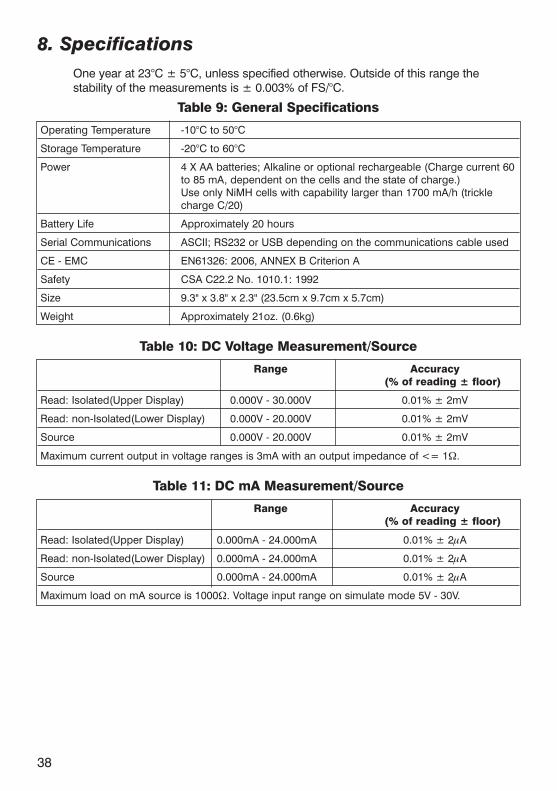
8. SpecificationsOne year at 23°C ± 5°C, unless specified otherwise. Outside of this range thestability of the measurements is ± 0.003% of FS/°C.
Table 9: General Specifications
Operating Temperature -10°C to 50°C
Storage Temperature -20°C to 60°C
Power 4 X AA batteries; Alkaline or optional rechargeable (Charge current 60to 85 mA, dependent on the cells and the state of charge.)Use only NiMH cells with capability larger than 1700 mA/h (trickle charge C/20)
Battery Life Approximately 20 hours
Serial Communications ASCII; RS232 or USB depending on the communications cable used
CE - EMC EN61326: 2006, ANNEX B Criterion A
Safety CSA C22.2 No. 1010.1: 1992
Size 9.3" x 3.8" x 2.3" (23.5cm x 9.7cm x 5.7cm)
Weight Approximately 21oz. (0.6kg)
Table 10: DC Voltage Measurement/Source
Range Accuracy (% of reading ± floor)
Read: Isolated(Upper Display) 0.000V - 30.000V 0.01% ± 2mV
Read: non-Isolated(Lower Display) 0.000V - 20.000V 0.01% ± 2mV
Source 0.000V - 20.000V 0.01% ± 2mV
Maximum current output in voltage ranges is 3mA with an output impedance of <= 1Ω.
Table 11: DC mA Measurement/Source
Range Accuracy (% of reading ± floor)
Read: Isolated(Upper Display) 0.000mA - 24.000mA 0.01% ± 2μA
Read: non-Isolated(Lower Display) 0.000mA - 24.000mA 0.01% ± 2μA
Source 0.000mA - 24.000mA 0.01% ± 2μA
Maximum load on mA source is 1000Ω. Voltage input range on simulate mode 5V - 30V.

39
Table 12: Frequency Measurement/SourceRange Accuracy
(% of reading ± floor)
Read 2.0CPM - 600.0CPM 0.05% ± 0.1CPM
1.0Hz - 1000.0Hz 0.05% ± 0.1Hz
1.00KHz - 10.00KHz 0.05% ± 0.01KHz
Source 2.0CPM - 600.0CPM 0.05%
1.0Hz - 1000.0Hz 0.05%
1.00KHz - 10.00KHz 0.250%Input voltage amplitude range on frequency is 1V to 20V zero based square wave only.Output amplitude isadjustable from 1V to 20V, and is a square wave with 50% duty cycle. For output frequency, a slight negative offsetof approximately -0.1V is present to assure zero crossing.
Table 13: Resistance Measurement
Range Accuracy(% of reading ± floor)
Ohms low 0.00Ω - 400.0Ω 0.015% ± 0.03Ω
Ohms high 401.0Ω - 4000.0Ω 0.015% ± 0.3Ω
Table 14: Resistance Source
Range Excitation Current Accuracy(% of reading ± floor)
Ohms low 5.0Ω - 400.0Ω 0.1mA - 0.5mA 0.015% ± 0.1Ω
5.0Ω - 400.0Ω 0.5mA - 3mA 0.015% ± 0.03Ω
Ohms high 400Ω - 1500Ω 0.05mA - 0.8mA 0.015% ± 0.3Ω
1500Ω - 4000Ω 0.05mA - 0.4mA 0.015% ± 0.3Ω
Note: Unit is compatible with smart transmitters and PLCs. Frequency response is <= 5ms.
Table 15: Thermocouple Measurement/Source
Range Accuracy(% of reading ± floor)
Read (mV) -10.000mV - 75.000mV 0.015% ± 10μV
Source (mV) -10.000mV - 75.000mV 0.015% ± 10μV
Maximum current output in voltage ranges is 1mA with an output impedance of <= 1Ω

40
Table 16: Thermocouple Read and Source (errors in °C)
Range (°C) Accuracy (°C)
TC Type Minimum Maximum CJC OFF CJC ON
J -210.0 -150.0 0.4 0.6
-150.0 1200.0 0.2 0.4
K -200.0 -100.0 0.5 0.7
-100.0 600.0 0.2 0.4
600.0 1000.0 0.3 0.5
1000.0 1372.0 0.4 0.6
T -250.0 -200.0 1.5 1.7
-200.0 0.0 0.5 0.7
0.0 400.0 0.2 0.4
E -250.0 -200.0 1.0 1.2
-200.0 -100.0 0.3 0.5
-100.0 1000.0 0.2 0.4
R1 0.0 200.0 1.7 1.9
200.0 1767.0 1.0 1.2
S1 0.0 200.0 1.7 1.9
200.0 1767.0 1.1 1.3
B1 600.0 800.0 1.5 1.7
800.0 1000.0 1.2 1.4
1000.0 1820.0 1.0 1.2
C 0.0 1000.0 0.5 0.7
1000.0 2316.0 1.5 1.7
XK -200.0 800.0 0.2 0.4
BP 0.0 800.0 1.9 2.1
800.0 2500.0 0.6 0.8
L -200.0 900.0 0.2 0.4
U -200.0 0.0 0.4 0.6
0.0 600.0 0.2 0.4
N -200.0 -100.0 0.8 1.0
-100.0 1300.0 0.3 0.5
CJC error outside of 23 ± 5°C is 0.05°C/°C
1. For thermocouple measure mode on B, R and S; round the specification up ordown accordingly as there is no resolution past the decimal point.

41
Table 17: RTD Read and Source
Accuracy (°C)RTD Type Range (°C) 1 year
Minimum Maximum Measure Measure 4W/Source 3W
P10(90)385 -200 100 0.85 2.20100 400 1.00 2.50400 800 1.20 2.80
P50(90)385 -200 100 0.20 0.50100 400 0.30 0.60400 800 0.40 0.70
P100(90)385 -200 100 0.15 0.25100 400 0.20 0.35400 800 0.30 0.45
P200(90)385 -200 100 0.40 0.50100 630 0.50 0.60
P400(90)385 -200 100 0.20 0.25100 630 0.25 0.30
P500(90)385 -200 100 0.20 0.25100 630 0.30 0.35
P1K(90)385 -200 100 0.15 0.20100 630 0.20 0.25
P50(90)391 -200 100 0.20 0.50100 400 0.30 0.60400 800 0.40 0.70
P100(90)391 -200 100 0.15 0.25100 400 0.20 0.35400 800 0.30 0.45
P100(90)392 -200 100 0.10 0.25100 630 0.20 0.35
M10(90)427 -100 260 0.75 2.00M50(90)428 -180 200 0.15 0.40M100(90)428 -180 200 0.10 0.20H120(90)672 -80 260 0.10 0.15P100(90)JIS -200 100 0.10 0.25
100 630 0.20 0.35YSI(90)400 15 50 0.10 0.15

42
9. Maintenance
9.1 Replacing BatteriesReplace batteries as soon as the battery indicator turns on to avoid falsemeasurements. If the batteries discharge too deeply the calibrator willautomatically shut down to avoid battery leakage.
Note: Use only AA size alkaline batteries or optional rechargeable batteries.
CautionDo not use charger with alkaline batteries
9.2 Cleaning the Unit
WarningTo avoid personal injury or damage to the calibrator, use only the specifiedreplacement parts and do not allow water into the case.
CautionTo avoid damaging the plastic lens and case, do not use solvents orabrasive cleansers.
Clean the calibrator with a soft cloth dampened with water or water and mildsoap.
9.3 Service Center Calibration or Repair Only qualified service personnel should perform calibration, repairs, orservicing not covered in this manual. If the calibrator fails, check thebatteries first, and replace them if needed.
Verify that the calibrator is being operated as explained in this manual. If thecalibrator is faulty, send a description of the failure with the calibrator. Besure to pack the calibrator securely, using the original shipping container if itis available.
!
!
!

9.4 Replacement Parts & Accessories
SPK-ASC-006 Operating Manual
124720 Mains adapter 9VDC/200mA - 230VAC/115VAC
SPK-HHC-002 Soft carrying case for the large handheld models includingshoulder strap
124004 Shoulder strap
2206011 Wire adapter kit - Type K thermocouple
2206012 Wire adapter kit - Type T thermocouple
104203 Test lead set
123958 RS232 cable 2 m / 6 ft (Stereo Jack to 9 pol D-sub)
121985 Extension Cable for Pt 100 Sensor - 5 m
121983 Extension Cable for Type K - 5 m
122523 Extension Cable for Type N - 5 m
120519 Thermocouple Male Plug - Type Cu-Cu - White
120518 Thermocouple Male Plug - Type R / S - Green
120517 Thermocouple Male Plug - Type K - Yellow
120516 Thermocouple Male Plug - Type J - Black
120515 Thermocouple Male Plug - Type T - Blue
120514 Thermocouple Male Plug - Type N - Orange
43SPK-ASC-006 Rev. D 1/14

Information in this document is subject to change without notice. ©2013, by AMETEK, Inc., www.ametek.com. All rights reserved.
www.ametekcalibration.com
AMETEK Test & Calibration InstrumentsA business unit of AMETEK Measurement &
Calibration Technologies Division offering the following industry leading brands for test and
calibration instrumentation.
JOFRA Calibration InstrumentsTemperature Calibrators
Portable dry-block calibrators, precision thermometers and liquid baths. Temperature
sensors for industrial and marine use.Pressure Calibrators
Convenient electronic systems ranging from -25 mbar to 1000 bar - fully temperature-
compensated for problem-free and accurate field use.
Signal InstrumentsProcess signal measurement and simulation for easy control loop calibration and measurement
tasks.
M&G Dead Weight Testers & PumpsPneumatic floating-ball or hydraulic piston dead
weight testers with accuracies to 0.015% of reading. Pressure generators delivering up to
1,000 bar.
Crystal PressureDigital pressure gauges and calibrators that are
accurate, easy-to-use and reliable. Designed for use in the harshest environments; most products
carry an IS, IP67 and DNV rating.
Lloyd Materials TestingMaterials testing machines and software that
guarantees expert materials testing solutions. Also covering Texture Analysers to perform rapid, general food testing and detailed texture analysis
on a diverse range of foods and cosmetics.
Davenport Polymer Test Equipment Allows measurement and characterization of
moisture-sensitive PET polymers and polymer density.
Chatillon Force MeasurementThe hand held force gauges and motorized
testers have earned their reputation for quality, reliability and accuracy and they represent the de
facto standard for force measurement.
Newage Hardness TestingHardness testers, durometers, optical systems and software for data acquisition and analysis.
United KingdomTel +44 (0)1243 833 [email protected]
FranceTel +33 (0)1 30 68 89 [email protected]
GermanyTel +49 (0)2159 9136 [email protected]
DenmarkTel +45 4816 [email protected]
USAFloridaTel +1 (800) 527 [email protected]
CaliforniaTel +1 (800) 444 [email protected]
IndiaTel +91 22 2836 [email protected]
Singapore Tel +65 6484 [email protected]
ChinaShanghaiTel +86 21 5868 5111
BeijingTel +86 10 8526 2111
GuangzhouTel +86 20 8363 [email protected]
Related Documents