1 Day ASA Workshop Lab Guide Overview This guide presents the instructions and other information concerning the activities for this course. You can find the solutions in the lab activity Answer Key. Outline This guide includes these activities: ■ Lab 1-1: Prepare to Use Cisco ASDM to Configure the Security Appliance ■ Lab 2-1: Configure the Security Appliance with Cisco ASDM (Hostname, Interfaces, Syslog, SNMP, Time Settings & PPPoE) ■ Lab 3-1: Enabling SSH and Telnet Access & Enabling Source IP Anti Spoofing ■ Lab 4-1: Configure a DMZ to enable access to a public DMZ server ■ Lab 5-1: Configure Basic SSL VPN functionality ■ Lab 6-1: Configure a Reverse Access Rule ■ Lab 8-1: Optional Labs ■ Lab 9-1: Configure Basic IPS (AIP-SSM) functionality IP Addressing is based on the SNAF course and may differ by course location: Outside ASA Interface: 192.168.P.2/24 ASA Default Gateway: 192.168.P.1/24 Outside NAT Address of DMZ Server: 192.168.P.11/24 Outside client PC address: Any IP coming in through the outside DMZ Server real address: 172.16.P.10/24 DMZ ASA Interface: 172.16.P.1/24 Inside Host (ASDM access): 10.0.P.10/24 Inside ASA Interface: 10.0.P.10/24 1 Day ASA 5505 Workshop v1.0 Page 1 of 69 © 2008 Cisco Systems, Inc

ASA-1day-Labguide(ajh)
Oct 27, 2015
Firewall asa lab guide
Welcome message from author
This document is posted to help you gain knowledge. Please leave a comment to let me know what you think about it! Share it to your friends and learn new things together.
Transcript

1 Day ASA Workshop Lab Guide Overview
This guide presents the instructions and other information concerning the activities for this course. You can find the solutions in the lab activity Answer Key.
OutlineThis guide includes these activities:
■ Lab 1-1: Prepare to Use Cisco ASDM to Configure the Security Appliance■ Lab 2-1: Configure the Security Appliance with Cisco ASDM
(Hostname, Interfaces, Syslog, SNMP, Time Settings & PPPoE) ■ Lab 3-1: Enabling SSH and Telnet Access & Enabling Source IP Anti Spoofing■ Lab 4-1: Configure a DMZ to enable access to a public DMZ server ■ Lab 5-1: Configure Basic SSL VPN functionality ■ Lab 6-1: Configure a Reverse Access Rule■ Lab 8-1: Optional Labs■ Lab 9-1: Configure Basic IPS (AIP-SSM) functionality
IP Addressing is based on the SNAF course and may differ by course location:
Outside ASA Interface: 192.168.P.2/24ASA Default Gateway: 192.168.P.1/24Outside NAT Address of DMZ Server: 192.168.P.11/24 Outside client PC address: Any IP coming in through the outside
DMZ Server real address: 172.16.P.10/24DMZ ASA Interface: 172.16.P.1/24
Inside Host (ASDM access): 10.0.P.10/24Inside ASA Interface: 10.0.P.10/24
The DMZ Server is running an FTP and HTTP server, as well as a protected CIFS service. The Inside Host is running a Syslog Server (such as 3C-Daemon or Kiwi) & Wireshark.
-----------------------------------------------------------------------------------------------------------------Please visit the following links to download and view useful information:http://www.cisco.com/en/US/products/ps6120/prod_models_comparison.html http://www.cisco.com/en/US/products/ps6120/prod_literature.html http://www.cisco.com/en/US/products/ps6120/products_data_sheets_list.html http://www.cisco.com/en/US/products/ps6120/prod_configuration_examples_list.html
1 Day ASA 5505 Workshop v1.0 Page 1 of 48 © 2008 Cisco Systems, Inc
Lab 1-1: Prepare to Use Cisco ASDM to Configure the Security ApplianceComplete this lab activity to practice what you learned in the related lesson.
Activity ObjectiveIn this activity, you will prepare to use Cisco ASDM to configure the security appliance. After completing this activity, you will be able to meet these objectives:■ Execute general commands■ Use the CLI to configure basic network settings■ Prepare the security appliance for configuration via Cisco ASDM
and launch Cisco ASDM
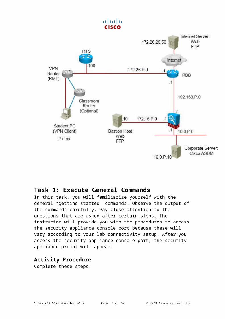
Visual ObjectiveThe figure illustrates what you will accomplish in this activity.
1 Day ASA 5505 Workshop v1.0 Page 2 of 48 © 2008 Cisco Systems, Inc
Task 1: Execute General CommandsIn this task, you will familiarize yourself with the general “getting started” commands. Observe the output of the commands carefully. Pay close attention to the questions that are asked after certain steps. The instructor will provide you with the procedures to access the security appliance console port because these will vary according to your lab connectivity setup. After you access the security appliance console port, the security appliance prompt will appear.
Activity ProcedureComplete these steps:
Step 1 Erase the default configuration of the security appliance. When prompted to confirm, press Enter.ciscoasa# write eraseErase configuration in flash memory? [confirm] <Enter>[OK]
Step 2 Reboot the security appliance. When prompted to confirm, press Enter.ciscoasa# reloadProceed with reload? [confirm} <Enter>
Step 3 After the security appliance reboots, it will prompt you to bootstrap it through interactive prompts. Press Ctrl-Z to escape. The unprivileged mode prompt is displayed. Pre-configure Firewall now through interactive prompts [yes]?<Control+Z>Type help or '?' for a list of available commands. ciscoasa>
Step 4 Display the list of help commands. ciscoasa> ?
Step 5 Enter the privileged mode of the security appliance. When prompted for a password, press Enter.ciscoasa> enablePassword:ciscoasa#
Step 6 Display the list of help commands. Press the spacebar on the keyboard to scroll through the list.ciscoasa# ?
1 Day ASA 5505 Workshop v1.0 Page 3 of 48 © 2008 Cisco Systems, Inc
Task 2: Initialize the Security ApplianceIn this task, you will prepare the security appliance for configuration via Cisco ASDM. You will first specify which physical interface will be used as the inside interface. You will then use the setup command interactive prompts to configure the basic parameters needed for accessing Cisco ASDM.
Activity ProcedureComplete these steps:
Step 1 Enter configuration mode.ciscoasa# configure terminal
Step 2 Specify Vlan1 as the inside vlan and accept the default security level.ciscoasa(config)# interface vlan1 ciscoasa(config-if)# nameif insideINFO: Security level for "inside" set to 100 by default.
Step 3 Assign interface E0/1 to the inside vlan (vlan1)ciscoasa(config)# interface e0/1 ciscoasa(config-if)# switchport access vlan 1
Step 4 Return to configuration mode.ciscoasa(config-if)# exit
Step 5 Enter the setup command to access the setup command interactive prompts.ciscoasa(config)# setup
Step 6 Press Enter to answer “yes” when prompted to preconfigure the firewall through interactive prompts.Pre-configure Firewall now through interactive prompts [yes]?<Enter>
Step 7 Press Enter to accept the default firewall mode, which is routed.Firewall Mode [Routed]: <Enter>
Step 8 Enter the enable password cisco123.Enable password [<use current password>]: cisco123
Step 9 Press Enter to answer “yes” when asked if you want to allow password recovery.Allow password recovery [yes]? <Enter>
Step 10 Press Enter to accept the year shown in brackets if it is correct. If not,
1 Day ASA 5505 Workshop v1.0 Page 4 of 48 © 2008 Cisco Systems, Inc

enter the current year.Clock (UTC):Year [2008]: <Enter>
Step 11 Press Enter to accept the month shown in brackets if it is correct. If not, enter the current month.Month [Mar]: <Enter>
Step 12 Press Enter to accept the day shown in brackets if it is correct. If not, enter the current day.Day [24]: <Enter>
Step 13 Press Enter to accept the time shown in brackets if it is correct. If not, enter the current time in hh:mm:ss format and 24-hour time.Time [09:48:06]: <Enter>
Step 14 Enter an IP address for the inside interface.Inside IP address [0.0.0.0]: 10.0.P.1
Step 15 Enter the network mask for the inside interface IP address.Inside network mask [255.255.255.255]: 255.255.255.0
Step 16 Enter a host name for the security appliance.Host name [ciscoasa]: asaP
Step 17 Enter a domain name for the security appliance.Domain name: training.com
Step 18 Enter the IP address of the corporate server, from which you will run Cisco ASDM.IP address of host running Device Manager: 10.0.P.10The following configuration will be used: Enable password: cisco123 Allow password recovery: yes Clock (UTC): 09:48:06 Mar 24 2008
Firewall Mode: RoutedInside IP address: 10.0.P.1Inside network mask: 255.255.255.0Host name: asaPDomain name: training.comIP address of host running Device Manager: 10.0.P.10
Step 19 Enter yes when asked if you want to use this configuration and write it to flash memory.Use this configuration and write to flash? Yes
1 Day ASA 5505 Workshop v1.0 Page 5 of 48 © 2008 Cisco Systems, Inc
Task 3: Launch Cisco ASDMIn this task, you will launch Cisco ASDM.
Activity ProcedureComplete these steps:
Step 1 Verify that Sun Java SE2 Plug-In 1.4.2, 1.5.0, or 1.6.0 is loaded on the corporate server (inside host behind the inside interface)
Step 2 Verify that encryption is enabled on the security appliance.What version of ASDM and ASA is in use?ASA?
ASDM?
asaP(config)# show versionCisco Adaptive Security Appliance Software Version 8.0(2) Device Manager Version 6.0(2)
Compiled on Fri 15-Jun-07 19:29 by builders System image file is "disk0:/asa802-k8.bin" Config file at boot was "startup-config"
asa1 up 3 hours 23 minsHardware: ASA5520, 512 MB RAM, CPU Pentium 4 Celeron 2000 MHzInternal ATA Compact Flash, 64MBBIOS Flash AT49LW080 @ 0xffe00000, 1024KBEncryption hardware device : Cisco ASA-55x0 on-board accelerator (revision 0x0)Boot microcode : .CN1000-MC-BOOT-2.00SSL/IKE microcode: .CNLite-MC-SSLm-PLUS-2.01IPSec microcode : .CNlite-MC-IPSECm-MAIN-2.040: Ext: GigabitEthernet0/0 : address is 0013.c482.2e52, irq 91: Ext: GigabitEthernet0/1 : address is 0013.c482.2e53, irq 92: Ext: GigabitEthernet0/2 : address is 0013.c482.2e54, irq 93: Ext: GigabitEthernet0/3 : address is 0013.c482.2e55, irq 94: Ext: Management0/0 : address is 0013.c482.2e51, irq 115: Int: Internal-Data0/0 : address is 0000.0001.0002, irq 116: Int: Internal-Control0/0 : address is 0000.0001.0001, irq 5Licensed features for this platform:Maximum Physical Interfaces : UnlimitedMaximum VLANs : 150Inside Hosts : Unlimited Failover : Active/ActiveVPN-DES : EnabledVPN-3DES-AES : Enabled
1 Day ASA 5505 Workshop v1.0 Page 6 of 48 © 2008 Cisco Systems, Inc

Security Contexts : 2GTP/GPRS : DisabledVPN Peers : 750WebVPN Peers : 2Advanced Endpoint Assessment : DisabledThis platform has an ASA 5520 VPN Plus license.Serial Number: JMX0944K06TRunning Activation Key: 0x96311f61 0xe8cc56cc0xe4138530 0x831454e0 0x8d34d9adConfiguration register is 0x2001Configuration last modified by enable_15 at10:00:59.276 UTC Tue Feb 18 2008
Step 3 Verify that the time and date on the security appliance and on the corporate server match. If they do not match, any issued certificates may not be valid.■ asaP(config)# show clock■ 09:03:38:832 UTC Mon Feb 25 2008
Notice that the clock defaults to UTC time. Make sure that the time and time zone match on the security appliance and on the device manager PC. If they do not, the certificate may not be valid.
Step 4 Check the version of Cisco ASDM on the security appliance.asaP(config)# show versionCisco Adaptive Security Appliance Software Version 8.2(1) Device Manager Version 6.2(1)
Step 5 If the show version output does not display “Device Manager Version 6.2 (1),” configure the Cisco ASDM image.asaP(config)# asdm image disk0:/asdm-621.bin
Step 6 Open the Internet Explorer web browser on the corporate server (internal host facing the inside interface of the ASA) and delete cookies by completing the following substeps:
1. From the Internet Explorer toolbar, choose Tools > Internet Options The Internet Options window opens.
2. Click Delete Cookies. The Delete Cookies window opens.
3. Click OK.
4. In the Internet Options window, click OK. Step 7 Access the Cisco ASDM console by completing the following substeps:
1 Day ASA 5505 Workshop v1.0 Page 7 of 48 © 2008 Cisco Systems, Inc
1. In the URL field of the browser window, enter https://10.0.P.1.
2. The Security Alert window opens. Click View Certificate. The Certificate pop-up window opens.3. Click Install Certificate. The Certificate Import Wizard pop-up window opens.
4. Click Next. The Certificate Import Wizard > Certificate Store panel is displayed.
5. Click Next. The Certificate Import Wizard > Completing the Certificate Import Wizard panel is displayed.
6. Click Finish. The Root Certificate Store pop-up window opens.
Note If a Security Warning window is displayed, click Yes.
7. Click Yes. The Certificate Import Wizard pop-up window opens.
8. Click OK.
9. Click OK in the Certificate window.
10. Click Yes in the Security Alert window. The Cisco ASDM 6.2 window opens.
11. Click Run ASDM. The Warning—Security pop-up window opens.
12. Click Yes.
13. If another Warning—Security pop-up window is displayed, click Run.
14. The Cisco ASDM Launcher login window is displayed.
15. If a pop-up window is displayed asking if you would like to create a shortcut on your desktop, click No.
16. Enter cisco123 in the Password field.
1 Day ASA 5505 Workshop v1.0 Page 8 of 48 © 2008 Cisco Systems, Inc
17. Click OK. Cisco ASDM should load now and display the Home window.
Step 8 Notice that the current security appliance configuration was imported.
Examine the configuration by clicking the Configuration icon and then completing the following substeps:
1. Select Device Setup from the navigation pane.
2. Click Interfaces. Notice that the inside interface is configured.
3. Select Device Name/Password. Notice that the host name asaP is displayed in the Hostname field and the domain name training.com is displayed in the Domain Name field of the Device Name/Password configuration pane.
4. Select Device Management from the navigation pane.
5. Expand the Management Access menu.
6. Select ASDM/HTTPS. Notice that IP address 10.0.P.10 is displayed in the list of hosts that are allowed to access the adaptive security appliance using Cisco ASDM
1 Day ASA 5505 Workshop v1.0 Page 9 of 48 © 2008 Cisco Systems, Inc
Lab 2-1: Configure the Security Appliance with Cisco ASDM (Hostname, Interfaces, Syslog, SNMP, Time Settings & PPPoE)Complete this lab activity to practice what you learned in the related lesson.
Activity ObjectiveIn this activity, you will learn how to configure a security appliance using Cisco ASDM. After completing this activity, you will be able to meet these objectives:
■ Use Cisco ASDM to configure basic network settings, including interface configurations & the hostname
■ Use Cisco ASDM to configure logging to a syslog server■ Configure basic SNMP functionality
Visual ObjectiveThe figure illustrates what you will accomplish in this activity.
1 Day ASA 5505 Workshop v1.0 Page 10 of 48 © 2008 Cisco Systems, Inc

Task 1: Run the Cisco ASDM Startup WizardIn this task, you will run the Cisco ASDM Startup Wizard.
Activity ProcedureComplete these steps:
Step 1 Choose Wizards > Startup Wizard from the main menu. The Startup Wizard opens, displaying the Starting Point (Step 1 of .) page.
Step 2 Verify that the Modify Existing Configuration radio button is selected.
---------------------------------------------------------------------------------------------Tip: If you would choose the “Reset Configuration to Factory Defaults”, you would reset the ASA to factory default.---------------------------------------------------------------------------------------------
Step 3 Click Next. The Basic Configuration (Step 2 of ...) page is displayed.
Step 4 Verify that asaP is displayed in the ASA Host Name field.Change the hostname to ASA-P (where P is your POD number)
Step 5 Verify that training.com appears in the Domain Name field.
Step 6 Click Next. The Interface Selection (Step 3 of ...) page is displayed.Create vlans for the following Inside vlan1Dmz vlan3Outside vlan4Make sure that all vlans are enabled
Step 7 Click Next. The Switch Port Allocation (Step 4 of ...) page is displayed.Assign the following ports to the appropriate vlanInside vlan1 int E0/1Dmz vlan3 int E0/2Outside vlan4 int E0/0
Step 8 Click Next. Interface IP Address Allocation (Step 5 of ...) page is displayed.Assign the following IP addresses ports to the appropriate vlanOutside IP 192.168.P.2 Mask 255.255.255.0Inside IP 10.0.P.1 Mask 255.255.255.0Dmz IP 172.16.P.1 Mask 255.255.255.0
Step 9 In the Static Routes (Step 6 of 10) page, click Next. The DHCP Server (Step 7 of 10) page is displayed. You will not be using DHCP at this time. Do not make any changes to this page.
1 Day ASA 5505 Workshop v1.0 Page 11 of 48 © 2008 Cisco Systems, Inc
Step 10 Click Next. The Address Translation (NAT/PAT) (Step 8 of 10) page is displayed.
Step 11 Select the Enable Traffic Through the Firewall Without Address Translation radio button. You will not be using NAT at this time.
Step 12 Click Next. The Administrative Access (Step 9 of 10) page is displayed.
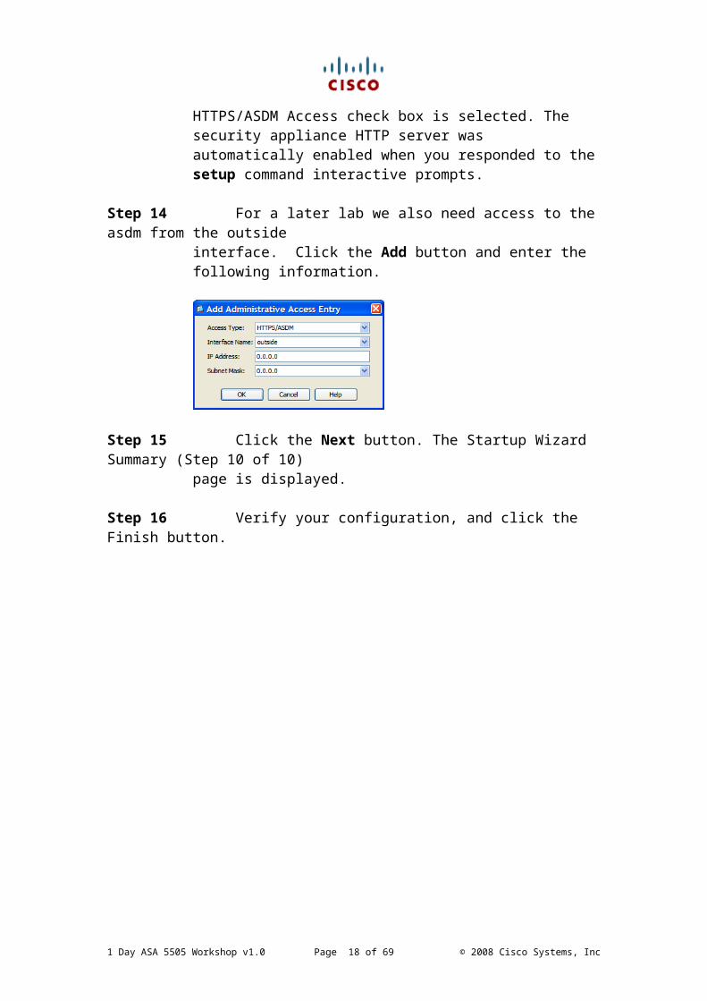
Step 13 Verify the information. Notice that the Enable HTTP Server for HTTPS/ASDM Access check box is selected. The security appliance HTTP server was automatically enabled when you responded to the setup command interactive prompts.
Step 14 For a later lab we also need access to the asdm from the outsideinterface. Click the Add button and enter the following information.
Step 15 Click the Next button. The Startup Wizard Summary (Step 10 of 10) page is displayed.
Step 16 Verify your configuration, and click the Finish button.
1 Day ASA 5505 Workshop v1.0 Page 12 of 48 © 2008 Cisco Systems, Inc

Task 2: Use Cisco ASDM to Configure Logging to a Syslog Server
In this task, you will configure syslog output to a syslog server. The instructor will provide you with the procedure to access a syslog server or host. This will vary according to the type of syslog server used in your classroom environment.
Note Verify that the syslog server or host is turned on and that the syslog service is installed and started.
Activity ProcedureComplete these steps:
Step 1 Verify that the Configuration button is selected in the Cisco ASDM toolbar.
Step 2 Click Device Management in the navigation pane.
Step 3 Expand the Logging menu.
Step 4 Click Logging Setup. The Logging Setup panel is displayed.
Step 5 Check the Enable Logging check box.
Step 6 Click Apply.Step 7 Click Syslog Servers in the Logging menu. The Syslog Servers panel is
displayed.Step 8 Click Add. The Add Syslog Server window opens.
Step 9 Choose inside from the Interface drop-down menu.
Step 10 Enter 10.0.P.10, the IP address of the syslog server, in the IP Address field.
Step 11 Click OK. You are returned to the Syslog Servers configuration panel.
Step 12 Click Apply.
Step 13 Click Logging Filters in the Logging menu.The Logging Filters panel is displayed.
Step 14 Click Syslog Servers in the Logging Destination column.
Step 15 Click Edit. The Edit Logging Filters window opens.
1 Day ASA 5505 Workshop v1.0 Page 13 of 48 © 2008 Cisco Systems, Inc
Step 16 In the Syslogs from All Event Classes area, click the Filter on Severity radio button.
Step 17 Choose Debugging from the Filter on Severity drop-down list.
Step 18 Click OK.
Step 19 Click Apply.
Step 20 Click Save in the toolbar. The Save Running Configuration to Flash window opens.
Step 21 Click Apply.
Task 3: Use Cisco ASDM to Configure Basic SNMP functionality
In this task, you will configure basic SNMP functionality.
Activity ProcedureComplete these steps:
Step 1 Verify that the Configuration button is selected in the Cisco ASDM toolbar.
Step 2 Click Device Management in the navigation pane.
Step 3 Click SNMPStep 4 Click Add. The SNMP Access Entry panel is displayed.
Step 5 Enter 10.0.P.10, the IP address of the SNMP server, in the IP Address field.
Step 6 Choose inside interface on how to reach the SNMP server on
Step 7 Choose a community string of cisco
Step 8 Choose the SNMP version 2c
Step 9 Choose UDP port 162 and select trap and poll options
Step 10 Click OK
Step 11 Click Apply followed by Send button
1 Day ASA 5505 Workshop v1.0 Page 14 of 48 © 2008 Cisco Systems, Inc

Task 4: Use Cisco ASDM to Configure Time SettingsIn this task, you will configure Time Settings.
Activity ProcedureComplete these steps:
Step 1 Verify that the Configuration button is selected in the Cisco ASDM toolbar.
Step 2 Click Device Setup in the navigation pane.
Step 3 Expand the System Time field
Step 4 Click Clock.
Step 5 Set the Timezone , Date and Time.
Step 6 Click Apply
Task 5: Use Cisco ASDM to Configure PPPoE
In this task, you will configure PPPoE : BUT NOT APPLY THE CHANGES
Activity ProcedureComplete these steps:Step 1 Verify that the Configuration button is selected in the Cisco ASDM
toolbar.
Step 2 Click Device Setup in the navigation pane.
Step 3 Choose Interfaces
Step 4 Select the outside interface and click edit
Step 5 Choose Use PPPoE
1 Day ASA 5505 Workshop v1.0 Page 15 of 48 © 2008 Cisco Systems, Inc

Step 6 Enter PPPoE credentials (Make up some example usernames and passwords)
Step 7 Click IP Address and Route Settings
Step 8 Choose Use PPPoE
Step 9 Choose Obtain default route using PPPoE
Step 10 Choose Cancel – in the live network you would select ok and apply
1 Day ASA 5505 Workshop v1.0 Page 16 of 48 © 2008 Cisco Systems, Inc
Lab 3-1: Enabling SSH and Telnet Access & Enabling Source IP Anti Spoofing
Complete this lab activity to practice what you learned in the related lesson.
Activity ObjectiveIn this activity, you will learn how to configure basic Security using Cisco ASDM. After completing this activity, you will be able to meet these objectives:
■ Enabling Telnet Access■ Enabling SSH Access ■ Enabling Source IP Anti Spoofing
Visual ObjectiveThe figure illustrates what you will accomplish in this activity.
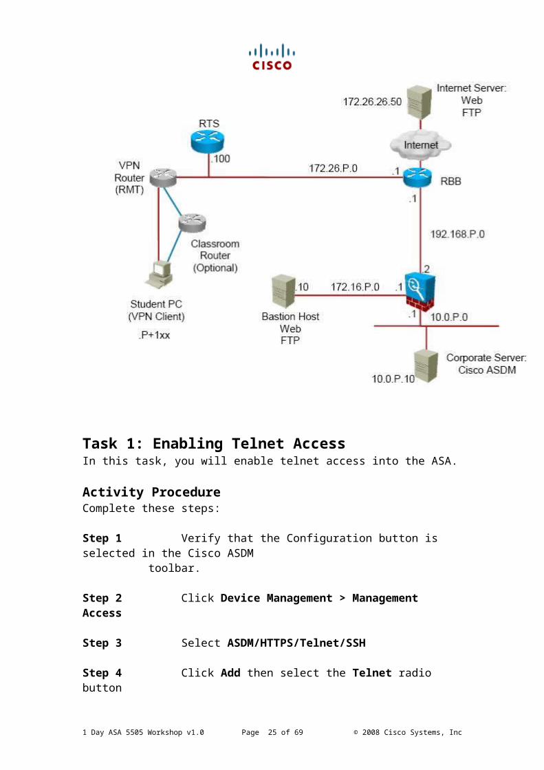
Task 1: Enabling Telnet Access
1 Day ASA 5505 Workshop v1.0 Page 17 of 48 © 2008 Cisco Systems, Inc
In this task, you will enable telnet access into the ASA.
Activity ProcedureComplete these steps:
Step 1 Verify that the Configuration button is selected in the Cisco ASDM toolbar.
Step 2 Click Device Management > Management Access
Step 3 Select ASDM/HTTPS/Telnet/SSH
Step 4 Click Add then select the Telnet radio button
Step 5 Select the network / mask from which telnet will be allowed (select your inside interface range and mask)
Step 6 Click OK
Step 7 Click Apply
Step 8 Click Send
Step 9 Verify that the Configuration button is selected in the Cisco ASDM toolbar.
Step 10 Click Device Management in the navigation pane.
Step 11 In the Users/AAA menu choose User accounts
Step 12 Select the Add button
Step 13 Assign username: cisco and password cisco123
Step 14 Choose Full Access and Privilege Level 15
Step 15 Click OK
Step 16 In the Users/AAA menu choose AAA
Step 17 Under the Authentication Tab enable the Server Group Local
Step 18 Tick Telnet and SSH boxes
Step 19 Click Apply
1 Day ASA 5505 Workshop v1.0 Page 18 of 48 © 2008 Cisco Systems, Inc
Step 20 Click OK
Step 21 Click Send
Step 22 From the inside host, launch a telnet to the inside IP address of the ASA
Task 2: Enabling SSH AccessIn this task, you will enable SSH access into the ASA.
Activity ProcedureComplete these steps:
Step 1 Verify that the Configuration button is selected in the Cisco ASDM toolbar.
Step 2 Click Device Management > Management Access
Step 3 Select ASDM/HTTPS/Telnet/SSH
Step 4 Click Add
Step 5 Select the SSH radio button
Step 6 Enter the network / mask from which SSH access will be allowed from (select your inside interface range and mask)
Step 7 Click OK
Step 8 Click Apply
Step 9 Click Send
Step 10 Using putty to test this ssh connection will fail, as the units do not yet have the necessary RSA keys generated to allow the ssh session to the unit
Step 11 This can either be done via the cli (easy) or the gui (harder to find)CLI ASA-4(config)# crypto key generate rsa general-keys modulus 1024GUI Configuration > Device Management > Certificate Management > Identity Certificates
Click Add, Select add a new identity certificate. “New” will generate key
1 Day ASA 5505 Workshop v1.0 Page 19 of 48 © 2008 Cisco Systems, Inc

Task 3: Enabling Source IP Anti SpoofingIn this task, you will enable Source IP Anti Spoofing Functionality
Activity ProcedureComplete these steps:
Step 1 Verify that the Configuration button is selected in the Cisco ASDM toolbar.
Step 2 Click Firewall in the navigation pane.
Step 3 Expand the Advanced tab
Step 4 Select Anti Spoofing
Step 5 Select the outside interface
Step 6 Select Enable
1 Day ASA 5505 Workshop v1.0 Page 20 of 48 © 2008 Cisco Systems, Inc
Lab 4-1: Configure a DMZ to enable access to a public DMZ serverComplete this lab activity to practice what you learned in the related lesson.At this point your laptop needs to move from the inside interface to the outside.
RE-ip your laptop to 192.168.P.10
Activity ObjectiveIn this activity, you will learn how to configure access to a server in the DMZ using Cisco ASDM. After completing this activity, you will be able to meet these objectives:
■ Configuring a static NAT rule■ Configuring an ACL rule to allow access to the DMZ from the outside
Visual ObjectiveThe figure illustrates what you will accomplish in this activity.
1 Day ASA 5505 Workshop v1.0 Page 21 of 48 © 2008 Cisco Systems, Inc

Task 1: Configuring a static NAT ruleIn this task, you will configure static translations for the bastion host
Activity ProcedureComplete these steps:
Step 1 In the NAT Rules panel, click Add.
Step 2 Choose Add Static NAT Rule from the Add menu. The Add Static NAT Rule window opens.
Step 3 Choose dmz from the Interface drop-down list in the Original area. Step 4 Enter 172.16.P.10 in the Source field of the Original area.
Step 5 Choose outside from the Interface drop-down list in the Translated area.
Step 6 Verify that the Use IP Address radio button is selected, and enter 192.168.P.11 in the corresponding field.
Step 7 Click OK.
Step 8 Click Apply in the NAT Rules panel.
Step 9 Use the Save button in the Cisco ASDM toolbar to save your configuration to flash memory.
Step 10 Complete the following substeps to test the functionality of the static translations you created:
1. From the Windows command line of the remote office server, attempt to establish an FTP session to the bastion host. You should be unable to access the bastion host via FTP without configuring an ACL to permit the inbound FTPTraffic to the bastion host. C:\> ftp 192.168.P.11
2. Open a web browser on the remote office server to test web access to the bastion host. Enter http://192.168.P.11 . You should be unable to access the bastion host via its static mapping without configuring an ACL to permit the inbound HTTP traffic to the bastion host
1 Day ASA 5505 Workshop v1.0 Page 22 of 48 © 2008 Cisco Systems, Inc
Task 2: Configure Inbound Access Rules on the Security Appliance
In this task, you will configure inbound access rules on the outside interface to perform these functions:■ Allow inbound web traffic from the outside network to the bastion host■ Allow inbound FTP traffic from the outside network to the bastion host
Activity ProcedureComplete these steps:
Step 1 Use the capture command to capture packets on the outside interface so that you can later view detailed information about packets and how they are processed by the security appliance.asaP(config)# capture OUTSIDE_CAP interface outside trace buffer 1534
Step 2 Open a web browser on the remote office server to test web access to the bastion server. Enter http://192.168.P.11 . You should be unable to access the bastion host via its static mapping without configuring an ACL to permit the inbound HTTP traffic to the bastion host.
Step 3 Display information about the packets that you captured on the outside interface.asaP(config)# show capture OUTSIDE_CAP2 packets captured1: 07:08:33.715584 172.26.26.50.2531 > 192.168.P.11.80: S 2401680706:2401680706(0) win 64512 <mss 1260,nop,nop,sackOK>2: 07:08:39.732277 172.26.26.50.2531 > 192.168.P.11.80: S 2401680706:2401680706(0) win 64512 <mss 1260,nop,nop,sackOK>2 packets shown
Step 4 Use the packet tracer to view the cause of your denied HTTP request to the bastion host by completing the following substeps. These substeps will enable you to trace an HTTP packet that is attempting to travel through the outside interface from the remote office server to the bastion server. This will also enable you to observe the lifespan of an HTTP packet through the security appliance.
1. Return to the Cisco ASDM session.
2. Click the Tools option in the Cisco ASDM menu bar.
1 Day ASA 5505 Workshop v1.0 Page 23 of 48 © 2008 Cisco Systems, Inc

3. Choose Packet Tracer. The Cisco ASDM Packet Tracer window opens.
4. Choose outside from the Interface drop-down list.
5. Verify that the TCP radio button is selected.
6. Enter 192.168.P.10 in the Source IP Address field.
7. Enter 1025 in the Source Port field.
8. Enter 192.168.P.11 in the Destination IP Address field.
9. Enter 80 in the Destination Port field.
10. Verify that the Show Animation check box is checked.
11. Click Start.
12. Expand the CAPTURE item in the Packet Tracer Phase panel. You should see the following information:
■ Type: CAPTURE■ Action: ALLOW■ Info: MAC Access list
13. Expand ACCESS LIST. You should see the following information:
■ Type: ACCESS-LIST■ Action: ALLOW■ Config: Implicit Rule■ Info: MAC Access list
14. Expand FLOW-LOOKUP. You should see the following information:
■ Type: FLOW-LOOKUP■ Action: ALLOW■ Info: Found no matching flow, creating a new flow
15. Expand UN-NAT. You should see the following information:■ Type: UN-NAT■ Subtype: Static■ Action: ALLOW
1 Day ASA 5505 Workshop v1.0 Page 24 of 48 © 2008 Cisco Systems, Inc
■ Config:— static (inside,outside) 192.168.P. 11 insidehost netmask
255.255.255.255— nat-control— match ip inside host insidehost outside any— static translation to 192.168.P.11— translate_hits = 0, untranslate_hits = 3
■ Info:— NAT divert to egress interface inside— Untranslate 192.168.P. 11/0 to insidehost/0 using
netmask 255.255.255.255
16. Expand ACCESS-LIST. You should see the following information:■ Type: ACCESS-LIST■ Action: DROP■ Config: Implicit Rule
17. Expand RESULT - The packet is dropped. You should see the following information:■ Info: (acl-drop) Flow is denied by configured rule.
18. Expand the second instance of ACCESS-LIST again.
19. Click Show Rule in Access Rule Table. Cisco ASDM displays the Access Rules table with the rule that denied the HTTP request highlighted.
Step 5 Complete the following substeps to create an ACL to permit inbound web access from the 192.168.P.0 network to the bastion host.
1. Click Access Rules in the Firewall menu within the navigation pane.
2. Click Add in the Access Rules panel.
3. Choose Add Access Rule. The Add Access Rule window opens.
4. Choose outside from the Interface drop-down list.
5. Verify that the Permit radio button is selected.
6. Enter 192.168.P.0/24 in the Source field.
1 Day ASA 5505 Workshop v1.0 Page 25 of 48 © 2008 Cisco Systems, Inc

7. Enter 192.168.P.11 in the Destination field.
8. Enter tcp/http in the Service field.
9. Click OK.
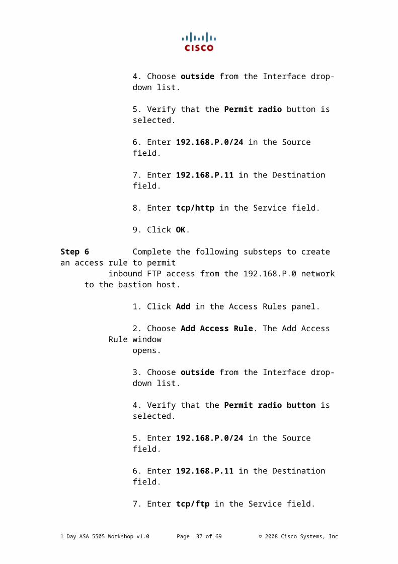
Step 6 Complete the following substeps to create an access rule to permit inbound FTP access from the 192.168.P.0 network to the bastion host.
1. Click Add in the Access Rules panel.
2. Choose Add Access Rule. The Add Access Rule window opens.
3. Choose outside from the Interface drop-down list.
4. Verify that the Permit radio button is selected.
5. Enter 192.168.P.0/24 in the Source field.
6. Enter 192.168.P.11 in the Destination field.
7. Enter tcp/ftp in the Service field.
8. Click OK.
9. From the Windows command line on the remote office server, establish an FTP session to the bastion host. You have reached the bastion host if you receive the Connected to 192.168.P.11 message. You should now be able to access the bastion host. C:\> ftp 192.168.P.11
Use the web browser on the remote office server to access the bastion host. You should now be able to access the bastion host. Enter http://192.168.P.11 .
1 Day ASA 5505 Workshop v1.0 Page 26 of 48 © 2008 Cisco Systems, Inc
Lab 5-1: Configure the Security Appliance to Provide Secure Clientless SSL VPN ConnectivityComplete this lab activity to practice what you learned in the related lesson.
Activity ObjectiveIn this activity, you will implement Clientless SSL VPN (WebVPN) on the Cisco ASA security appliance. After completing this activity, you will be able to meet these objectives:■ Use Cisco ASDM to configure the security appliance for basic SSL VPN services■ Use Cisco ASDM to configure users and groups for SSL VPN services■ Test and verify security appliance SSL VPN connectivity
ScenarioYour company wants to implement remote access using remotely located PCs that terminate at a centrally located Cisco ASA security appliance, without using any client software. You must configure the security appliance for remote access using the WebVPN feature set.
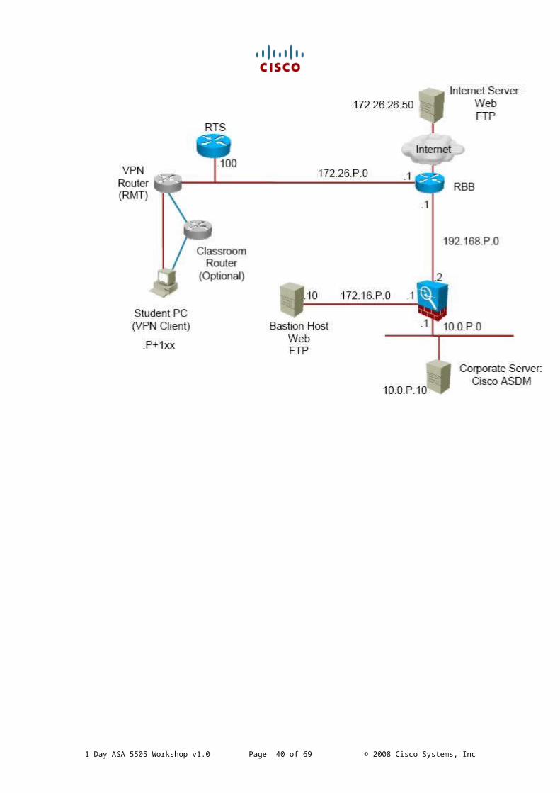
Visual ObjectiveThe figure illustrates what you will accomplish in this activity.
1 Day ASA 5505 Workshop v1.0 Page 27 of 48 © 2008 Cisco Systems, Inc

1 Day ASA 5505 Workshop v1.0 Page 28 of 48 © 2008 Cisco Systems, Inc
Task 1: Use the SSL VPN Wizard to Configure a Secure SSL VPNIn this task, you will use the SSL VPN Wizard in Cisco ASDM to configure the corporate adaptive security appliance for SSL VPN connections.
Activity ProcedureComplete these steps:
Step 1 Return to your Cisco ASDM session on the inside server.
Step 2 Click Wizards in the Cisco ASDM menu bar.
Step 3 Choose SSL VPN Wizard. The SSL VPN Connection Type page of the wizard is displayed.
Step 4 Verify that the Clientless SSL VPN Access check box is checked.
Step 5 Click Next. The SSL VPN Interface page is displayed.
Step 6 Complete the following substeps to configure a connection profile name and specify the interface that users will access for SSL VPN connections:
1. Enter AUSTIN in the Connection Name field.
2. Verify that outside is displayed in the SSL VPN Interface drop-down list. If it is not, choose outside from the drop-down list.
3. Click Next. The User Authentication page is displayed.
Step 7 Complete the following substeps to configure authentication for the SSL VPN:
1. Check the Authenticate Using the Local User Database radio button.
2. Enter cisco in the Username field.
3. Enter cisco in the Password field.
4. Enter cisco in the Confirm Password field.
5. Click Add. The user name is displayed in the field to the right of the Add button.
6. Click Next. The Group Policy page is displayed.
1 Day ASA 5505 Workshop v1.0 Page 29 of 48 © 2008 Cisco Systems, Inc
Step 8 Complete the following substeps to create a group policy to group attributes that are common to specific groups of users:
1. Verify that the Create a New Group Policy radio button is selected. If it is not, select it.
2. Enter FIRSTGROUP in the corresponding field.
3. Click Next. The Clientless Connections Only—Bookmark List page is displayed.
Step 9 Complete the following substeps to create a bookmark list for the SSL
VPN end-user portal:
1. Click Manage. The Configure GUI Customization Objects window opens.
2. Click Add. The Add Bookmark List window opens.
3. Enter URLs in the Bookmark List Name field.
4. Click Add. The Add Bookmark Entry window opens.
5. Enter INTRANET in the Bookmark Title field.
6. Choose http from the URL Value drop-down list to add a file-sharing bookmark.
7. In the corresponding URL field, enter 172.16.P.10/inside.htm
8. Click OK.
9. Click OK in the Add Bookmark List window.
10. Click OK in the Configure GUI Customization Objects window. The bookmark list name “URLs” is displayed in the Bookmark List field on the Clientless Connections Only—Bookmark List page.
11. Click Next. The Summary page is displayed.
Step 10 Review your configuration in the Summary page. If you are satisfied with the configuration, click Finish to apply the changes to the adaptive security appliance.
1 Day ASA 5505 Workshop v1.0 Page 30 of 48 © 2008 Cisco Systems, Inc

Step 11 Click the Save button in the Cisco ASDM toolbar.
Step 12 Complete the following substeps to verify that user cisco is configured to inherit settings from the FIRSTGROUP group policy:
1. Click the Configuration button in the Cisco ASDM toolbar.
2. Click Device Management in the navigation pane.
3. Expand the Users/AAA menu.
4. Click User Accounts. The User Accounts panel is displayed.
5. In the user accounts table, verify that VPN group policy FIRSTGROUP is assigned to user cisco.
Step 13 Minimize the Cisco ASDM window.
Task 2: Test Your SSL VPNIn this task, you will test and verify your SSL VPN.
Activity ProcedureComplete these steps:
Step 1 Open a web browser on the remote office server. Step 2 Enter https://192.168.P.2 to access the outside interface of the corporate adaptive security appliance, which you configured to accept Clientless SSL VPN connections. A Security Alert window opens.
Step 3 Click Yes.
Step 4 Log in to the SSL VPN service with the username cisco and the password cisco. The SSL VPN Service window displays the Home page.
Step 5 Complete the following substeps to test the file-sharing bookmark you created with the SSL VPN Wizard:
1 Day ASA 5505 Workshop v1.0 Page 31 of 48 © 2008 Cisco Systems, Inc

1. Click the INTRANET link under File Bookmarks.
2. Select the url to test the link
1 Day ASA 5505 Workshop v1.0 Page 32 of 48 © 2008 Cisco Systems, Inc

Lab 6-1: Configure a Reverse Access RuleComplete this lab activity to practice what you learned in the related lesson.
Activity ObjectiveIn this activity, you will configure a Reverse Access Rule on the Cisco ASA security appliance. After completing this activity, you will be able to meet these objectives:■ Use Cisco ASDM Real-Time Log Viewer to determine why a connection from the outside world to port 23 (Telnet) on the DMZ server is blocked■ Use Cisco ASDM Real Time Log Viewer to create a Reverse Access Rule■ Test and verify security appliance connectivity after the new rule is in place
Visual ObjectiveThe figure illustrates what you will accomplish in this activity.
1 Day ASA 5505 Workshop v1.0 Page 33 of 48 © 2008 Cisco Systems, Inc
Task 1: Use the ASDM Real Time Log Viewer to determine why telnet Access from an outside machine to the DMZ server is deniedIn this task, you will use the Cisco ASDM Real Time Log Viewer to determine why a telnet connection to the DMZ is denied.
Activity ProcedureComplete these steps:
Step 1 Return to your Cisco ASDM session on the inside server.
Step 2 Click Monitoring> Logging in the Cisco ASDM menu bar.
Step 3 Choose View. The Real Time log viewer is displayed.
Step 4 Verify that the Resume box is clicked.
Step 5 Go to the Outside machine (IP address will be given to you) and follow the following steps:
1. Telnet to 192.168.P.11 from the CMD.exe bash
2. The connection will be unsuccessful
3. Return to the ASDM Real Time Log Viewer
Step 6 You will see the log event related to your unsuccessful telnet attempt
Task 2: Create a Reverse Access RuleIn this task, you will create a reverse Access Rule.
Activity ProcedureComplete these steps:
Step 1 Right Click the log event which indicated the blocked telnet attempt Step 2 Select Create Reverse Access Rule
Step 3 Leave the values in the popped up window untouched
Step 4 Enter a description of “Reverse Access Rule for Telnet” in the
1 Day ASA 5505 Workshop v1.0 Page 34 of 48 © 2008 Cisco Systems, Inc
Description field.
Step 5 Delete the Source Service entry (this is because a subsequent connection destined for port 23 will use a different source port than the previous session captured)
Step 6 Click OK
Step 7 Click Apply
Step 8 Click Send
Step 9 Go to the Outside machine (IP address will be given to you) and follow the following steps:
1. Telnet to 192.168.P.11 from the CMD.exe bash
2. The connection will be Successful
1 Day ASA 5505 Workshop v1.0 Page 35 of 48 © 2008 Cisco Systems, Inc

Lab 7-1: Optional LabsComplete this lab activity to practice what you learned in the related lesson.
Activity ObjectiveIn this activity, you will perform a couple of additional lab exercises. After completing this activity, you will be able to meet these objectives:■ Use Cisco ASDM Packet Capture Functionality ■ Enabling the EIGRP routing process on the ASA firewall■ Enabling Application Inspection for FTP
Visual ObjectiveThe figure illustrates what you will accomplish in this activity.
1 Day ASA 5505 Workshop v1.0 Page 36 of 48 © 2008 Cisco Systems, Inc
Task 1: Packet CaptureIn this task, you will use the Cisco ASDM Packet Capture Functionality to capture packet flows.
Activity ProcedureComplete these steps:
Step 1 Return to your Cisco ASDM session on the inside server.
Step 2 Go to Tools -> Preferences
Step 3 Ensure the Wireshark path matches the installation path on the inside machine from where you launched the ASDM
Step 4 Click OK
Step 5 Go to Wizards -> Packet Capture Wizard
Step 6 Click Next
Step 7 Choose 0.0.0.0 0.0.0.0 (any/any) for source and destination networks
Step 8 Choose the inside interface to capture packets on
Step 9 Choose protocol tcp for all services
Step 10 Click Next
Step 11 Click Next (default outbound services)
Step 12 Click Next (default packet sizes)
Step 13 Click Next (verify the entries which are being used)
Step 14 Click Start
Step 15 Wait 5 seconds
Step 16 Click Stop
Step 17 Click Get Packet Capture to review captured packets
1 Day ASA 5505 Workshop v1.0 Page 37 of 48 © 2008 Cisco Systems, Inc

Task 2: Preparing the ASA for EIGRP RoutingIn this task, you will configure the EIGRP routing on the ASA.
Activity ProcedureComplete these steps:
Step 1 Go to Configuration -> Device Setup Step 2 Expand the Routing tab
Step 3 Expand the EIGRP routing tab
Step 4 Go to Setup
Step 5 Tick Enable this EIGRP process
Step 6 Enter 100 for the EIGRP AS number
Step 7 Click Apply
Step 8 Click Send
Step 9 Choose the Networks Tab
Step 10 Click Add
Step 11 Enter 10.0.0.0 in the network field
Step 12 Choose 255.255.255.0 in the network mask field
Step 13 Click OK
Step 14 Click Apply
Step 15 Click Send
1 Day ASA 5505 Workshop v1.0 Page 38 of 48 © 2008 Cisco Systems, Inc
Task 3: Enabling application inspection for FTPIn this task, you will configure FTP application inspection on the ASA.
Activity ProcedureComplete these steps:
Step 1 Go to Configuration -> Firewall -> Objects -> Class Maps -> FTP Step 2 Click Add
Step 3 Enter ftp_class_map in the Name field
Step 4 Select Match Any
Step 5 Click Add
Step 6 Choose Request-Command as match criterion Step 7 Tick the Put option
Step 8 Click OK
Step 9 Click Apply
Step 10 Click Send
Step 11 Go to Configuration -> Firewall -> Objects -> Inspect Maps -> FTP
Step 12 Click Add
Step 13 Enter ftp_inspect in the Name field
Step 14 Click Apply
Step 15 Click Details
Step 16 Click the Inspections tab
Step 17 Click Add
Step 18 Tick Multiple Matches
Step 19 Choose the previously created traffic class ftp_class_map
Step 20 Click OKStep 21 Click OK
1 Day ASA 5505 Workshop v1.0 Page 39 of 48 © 2008 Cisco Systems, Inc
Step 22 Click Apply
Step 23 Click Send
Step 24 Go to Firewall -> Service Policy rules in the left navigation pane
Step 25 Click Add
Step 26 Tick the interface button and select the inside interface
Step 27 For the Policy-Name enter: ftp_policy
Step 28 Click Next
Step 29 Select the Create a New Traffic Class button
Step 30 Name the traffic class: ftp-class
Step 31 Tick the Default Inspection Traffic box
Step 32 Click Next
Step 33 Click Next
Step 34 Select FTP
Step 35 Select Configure
Step 36 Select Use Strict FTP
Step 37 Tick Select a FTP inspect map….
Step 38 Click OK
Step 39 Click Finish
Step 40 Click Apply
Step 41 Click Send
Step 42 Open an FTP session from the CMD window of the inside machine to the DMZ FTP server and try to upload a file and observe the results.
1 Day ASA 5505 Workshop v1.0 Page 40 of 48 © 2008 Cisco Systems, Inc
Lab 8-1: Initializing the Cisco ASA AIP SSMComplete this lab activity to practice what you learned in the related lesson.Please verify the IP addressing with your instructor.
Activity ObjectiveIn this activity, you will load and initialize Cisco IPS software on the Cisco ASA AIP SSM. After completing this activity, you will be able to meet these objectives:
Verify the Cisco ASA AIP SSM Load the Cisco IPS recovery software on the Cisco ASAAIP SSM Configure the Cisco ASA AIP SSM setup parameters Configure a Cisco IPS security policy on the security appliance Verify the Cisco IPS security policy
Visual ObjectiveThe figure illustrates what you will accomplish in this activity.
1 Day ASA 5505 Workshop v1.0 Page 41 of 48 © 2008 Cisco Systems, Inc
Task 1: Verify the Cisco ASA AIP SSMIn this task, you will view the Cisco ASA AIP SSM status.
Activity ProcedureComplete these steps:
Step 1 View the status of both the Cisco ASA security appliance and the Cisco ASA AIP SSM.
asaP# show moduleasaP# show module 1 detailasaP# show module 1 recover
Task 2: Configure the Cisco ASA AIP SSM Setup ParametersNow you will need to configure the setup parameters. Once the setup parameters are configured, ASDM can connect to the Cisco ASA AIP SSM. In this task, you will configure the Cisco ASA AIP SSM setup parameters.
Activity ProcedureComplete these steps:
Step 1 From the command line, session into the Cisco ASA AIP SSM.asaP# session 1
Step 2 The first time the administrator initiates a session with the Cisco ASA AIP SSM, the administrator will be prompted to log in. Enter the default login, cisco, and password, cisco.Login: ciscoPassword: cisco
Step 3 After entering the default login and password, the administrator will be prompted to change the password. Enter training as the new password.
You are required to change your password immediately (password aged) Changing password for cisco(current) UNIX password: ciscoNew password: trainingRetype new password: training.………….sensor#
Step 4 To access the Cisco ASA AIP SSM via ASDM, the network parameters
1 Day ASA 5505 Workshop v1.0 Page 42 of 48 © 2008 Cisco Systems, Inc
must be set. To set these parameters, enter setup mode.sensor# setup
Step 5 To modify the setup configuration, continue with the configuration dialog.Continue with configuration dialog?[yes]: yes
Step 6 Change the host name to sensorP. (where P = pod number)Enter host name [sensor]: sensorP
Step 7 Change the IP address of the external Cisco ASA AIP SSM interface to the following:Enter IP interface[10.0.P.201/24,10.0.P.1]: 10.0.P.41/24,10.0.P.1 (to be confirmed by the instructor)(where P = pod number)
Step 8 Press Enter for the change telnet-server status leaving it in the default state of disabled.
Step 9 Press Enter for web-server port taking the default port of 443.
Step 10 Add your student PC (inside LAN) to the list of hosts that can gain access to the Cisco ASA AIP SSM through the external interface.Modify current access list?[no]: yesCurrent access list entries:No entriesPermit: 10.0.P.0/24Permit: <Enter>(where P = pod number)
Step 11 Press Enter for the remaining entries in the setup menu until you encounter the message The Following Configuration Was Entered. From the display, verify that the host IP address is correct and that the host name was changed to sensorP. (where P = pod number)
Step 12 If the changes are correct, save this configuration and exit setup mode.Exit[0] Goto command prompt without saving this config.[1] Return back to setup without saving this config.[2] Save this configuration and exit setup.
Enter your selection[2]: <Enter>Configuration saved.sensor#
1 Day ASA 5505 Workshop v1.0 Page 43 of 48 © 2008 Cisco Systems, Inc

Step 13 Verify your configuration, host IP, host name, and ACL.sensor# show configuration
Step 14 Verify the current user.Sensor# show usersCLI ID User Privilege* 431 cisco administrator
Step 15 Exit the Cisco ASA AIP SSM session.sensor# exitRemote card closed command session. Press any key to continue. <Enter>Command session with slot 1 terminated.asa1#
Step 16 Verify the path between your student PC (inside LAN) and the Cisco ASA AIP SSM. From your student PC, a ping to the Cisco ASA AIP SSM external interface should be successful.C:\> ping 10.0.P.41(where P = pod number)
Task 4: Configure a Cisco IPS Security Policy on the Security ApplianceSo far in this lab, you have initialized the Cisco ASA AIP SSM. You have gained access to the module via ASDM. Next, you need to configure a Cisco IPS modular policy. In this task, you will configure the modular policy for Cisco IPS traffic inspection of any traffic from the inside host to the outside.
Activity ProcedureComplete these steps:
Step 1 Log in to ASDM.
Step 2 From the ASDM Configuration features, choose Security Policy. The Security Policy window will open.
Step 3 In the Security Policy window, click the Service Policy Rules tab.
Step 4 Click Add. The Add Service Policy Rule Wizard—Service Policy window will open.
Step 5 In the Add Service Policy Rule Wizard—Service Policy window, configure a service policy and assign it to an interface. To configure a service policy and assign it to an interface, complete the following substeps:
1 Day ASA 5505 Workshop v1.0 Page 44 of 48 © 2008 Cisco Systems, Inc
1. Verify that the Interface button is selected.2. From the Interface drop-down menu, choose Inside—(Create New Service Policy).
3. In the Policy Name field, verify the policy name assigned by the ASDM, inside-policy.
4. Click Next. The Add Service Policy Rule Wizard—Traffic Classification Criteria window will open.
Step 6 In the Add Service Policy Rule Wizard—Traffic Classification window, configure a traffic-matching criterion as follows. Select the Source and Destination IP Address (Uses ACL) check box. Click Next. The Add Service Policy Rule Wizard—Traffic Match—Source and Destination Address window will open.
Step 7 In the Add Service Policy Rule Wizard—Traffic Match—Source and Destination Address window, verify that Match is selected in the Action drop-down menu.
1. Choose IP Address from the Source Type drop down list.
2. Choose insidesidehost from the IP Address drop-down list and 255.255.255.255 from the Netmask drop-down list in the Source group box.
Note, you will need to create the insidehost on the ASA first and define a NAT / ACL rule for this host to communicate with the outside world. This is a good exercise to practise the skills obtained in the DMZ section. You may browse back for reference.
3. Choose any from the Type drop-down list in the Destination group box.
4. Click Next. The Add Service Policy Rule Wizard—Rule Actions window will open.
Step 8 In the Add Service Policy Rule Wizard—Rule Actions window, configure the Cisco IPS rule by completing the following substeps:
1. Under the Intrusion Prevention tab, check the Enable IPS for This Traffic Flow check box.
2. In the Mode group box, verify that the Inline Mode button is selected.
1 Day ASA 5505 Workshop v1.0 Page 45 of 48 © 2008 Cisco Systems, Inc

3. In the If IPS Card Fails, Then group box, verify that the Permit Traffic button is selected.
4. Click Finish. You will be returned to the Service Policy Rules window.
Step 9 In the Service Policy Rules window, click Apply. The Preview CLI Commands window will open.
Step 10 In the Preview CLI Commands window, view the access-list, class map, policy map, and service policy CLI commands before they are sent to the security appliance. Click Send.
Task 5: Verify IPS Security PolicyIn this task, you will configure the security appliance to monitor intrusion detection.
Activity ProcedureComplete these steps:
Step 1 From the CLI command prompt, view the class map used by the security appliance to identify a class of traffic.asaP# show run class-mapclass-map inside-classmatch access-list inside_mpc
Step 2 From the CLI command prompt, view the ACL used by the security appliance to identify matching traffic to be copied to the Cisco ASA AIP SSM.asaP# show run access-list………access-list inside_mpc extended permit ip host insidehost any
Step 3 From the CLI command prompt, view the policy map used by the security appliance to apply the Cisco IPS policy to a class of traffic.asaP# show run policy-mappolicy-map inside-policyclass inside-classIPS inline fail-open
Step 4 From the CLI command prompt, view the interface to which the service policy was applied.asaP# show run service-policyservice-policy inside-policy interface inside
1 Day ASA 5505 Workshop v1.0 Page 46 of 48 © 2008 Cisco Systems, Inc

Step 5 Verify that inbound ICMP packets from the inside host are being copied and sent to the Cisco ASA AIP SSM. From the Windows command line, ping 172.26.26.50 continuously with an ICMP packet size of 1000.C:\> ping –l 1000 172.26.26.50 -tPinging 172.26.26.50 with 100 bytes of data:Reply from 172.26.26.50: bytes=1000 time<10ms TTL=125>Reply from 172.26.26.50: bytes=1000 time<10ms TTL=125>Reply from 172.26.26.50: bytes=1000 time<10ms TTL=125>Reply from 172.26.26.50: bytes=1000 time<10ms TTL=125>
Step 6 Verify that the service policy is identifying ICMP packets.asaP# show service-policy……………Interface inside:
Service-policy: inside-policy Class-map: inside-class IPS: card status Up, mode inline fail-open
packet input 22, packet output 22, drop 0, reset-drop 0
Step 7 Verify that the security appliance is sending packets to the Cisco ASA AIP SSM via the internal data channel. Complete the following substeps to view the statistics.
1. Open a session with the Cisco ASA AIP SSM.asaP# session 1
2. Log in to the Cisco ASA AIP SSM.login: ciscopassword: training
3. Confirm that data packets are being routed to the Cisco ASA AIP SSM internal data channel.sensorP# show interface…………Mac statistics from interface GigabitEthernet0/1…………Media Type = backplane…………Total Packets Received = 81Total Bytes Received = 75353
4. Confirm that the data packets count is incrementing.sensorP# show interface…………Mac statistics from interface GigabitEthernet0/1…………
1 Day ASA 5505 Workshop v1.0 Page 47 of 48 © 2008 Cisco Systems, Inc

Media Type = backplane…………Total Packets Received = 92Total Bytes Received = 87409
5. Exit the Cisco ASA AIP SSM session.SensorP# exitRemote card closed command session. Press any key to continue. <Enter>Command session with slot 1 terminated.asaP#
Step 8 In the Command Line window, press Ctrl-C to end the continuous ping.
Step 9 Close the command prompt window.
Step 10 In the ASDM window, click the Save icon. The Save Running Configuration to Flash window will open.
Step 11 Click Yes. The Preview CLI Commands window will open.
Step 12 Click Send.
Step 13 Close the ASDM window.
Step 14 The Are You Sure window will open. Click Yes.Close all open browser windows
Step 15 OPTIONAL: Try to access the AIP-SSM IPS module through ASDM and familiarize yourself with the configuration options through ASDM
1 Day ASA 5505 Workshop v1.0 Page 48 of 48 © 2008 Cisco Systems, Inc
Related Documents