AS5011 Integrated Hall IC for navigation keys DATASHEET EasyPoint EP40-101 Navigation Module Benefits • High reliability due to magnetic non-contact sensing • Low power consumption • 3 operating modes Shutdown mode ( 12.5Hz, 50μA current) Low Power mode ( 50Hz, 200μA current) Full Power mode ( 2600Hz, 8mA current) Key Features • XY coordinates direct read • 2.7 to 3.6V operating voltage • Down to 1.8V I/O voltage • Lateral magnet movement radius up to 1mm • I²C interface up to 4 MHz • Configurable interrupt output for motion detection • Push button output Applications The EasyPoint EP40-101 is ideal for small factor manual input devices in battery operated equipment, such as • Mobile phones • MP3 players • PDA’s • GPS receivers • Gaming consoles • Analog joystick replacement EasyPoint™ EP40-101 is a miniature joystick module concept based on contact-less, magnetic movement detection. The integrated two-dimensional linear encoder monitors the movement of the magnet incorporated in the knob and provides directly the x and y coordinates via I²C output. An integrated mechanical push button built in the module provides a “select” function. Typical application Revision 1.0 – 08.07.2009 www.austriamicrosystems.com Page 1 of 14

Welcome message from author
This document is posted to help you gain knowledge. Please leave a comment to let me know what you think about it! Share it to your friends and learn new things together.
Transcript
AS5011 Integrated Hall IC for navigation keys
DATASHEETEasyPoint EP40-101 Navigation Module
Benefits • High reliability due to magnetic non-contact sensing
• Low power consumption
• 3 operating modes Shutdown mode ( 12.5Hz, 50µA current) Low Power mode ( 50Hz, 200µA current) Full Power mode ( 2600Hz, 8mA current)
Key Features • XY coordinates direct read
• 2.7 to 3.6V operating voltage
• Down to 1.8V I/O voltage
• Lateral magnet movement radius up to 1mm
• I²C interface up to 4 MHz
• Configurable interrupt output for motion detection
• Push button output
Applications The EasyPoint EP40-101 is ideal for small factor manual input devices in battery operated equipment, such as
• Mobile phones
• MP3 players
• PDA’s
• GPS receivers
• Gaming consoles
• Analog joystick replacement
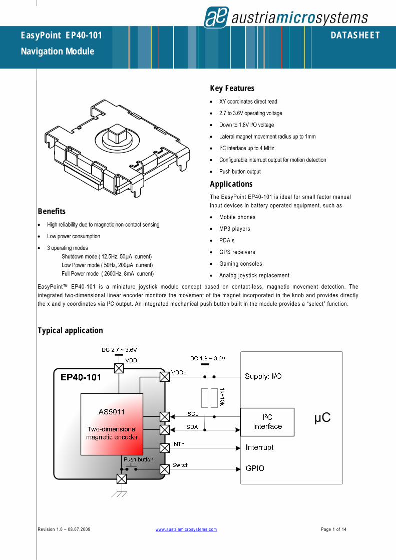
EasyPoint™ EP40-101 is a miniature joystick module concept based on contact-less, magnetic movement detection. The integrated two-dimensional linear encoder monitors the movement of the magnet incorporated in the knob and provides directly the x and y coordinates via I²C output. An integrated mechanical push button built in the module provides a “select” function.
Typical application
Revision 1.0 – 08.07.2009 www.austr iamicrosystems.com Page 1 of 14

EP40-101 navigation module
1 Mechanical drawing
FPC connector, 9 pin 0 .5mm p itch, 0.3mm thickness
Kyocera 04-6299-009-020-829+
Figure 1: EP40-101 dimensions (mm ±0.15)
Connector edge (left side)
Figure 2: Recommended PCB layout (dimensions in mm ±0.15)
Revision 1.0 – 08.07.2009 www.austr iamicrosystems.com Page 2 of 14

1.1 XY coordinates interpretation
1.1.1 EasyPoint operating principle
11X
Y
Xp
Xn
Yp
Yn
1mm
Con
nector Side
Connector S
ide
Xp
Xn
Yp
Yn
Connector S
ide
Xp
Xn
Yp
Yn
1 2 3X=0mm X_Reg=0 Y=0mm Y_Reg=0 Xn = -10 Yn = -10 Xp = 10 Yp = 10
Int = 1 (not active)
X = 0.5mm X_Reg = 15 (±3) Y = 0mm Y_Reg = 0 Xn = -10 Yn = -10 Xp = 10 Yp = 10 X_Reg>Xp Int = 0 (active)
X = 1mm X_Reg = 31 (±5) Y = 0mm Y_Reg = 0 Xn = -10 Yn = -10 Xp = 10 Yp = 10 X_Reg>Xp Int = 0 (active)
Figure 3: Mechanical to XY register interpretation
On the following example, the interrupt threshold values Xp Xn Yp Yn (see the I²C register list) have been set by the user to
Xp=10 Xn=-10 Yp=10 Yn=-10. Those four registers are programmable independently for the four directions.
In Shutdown mode (50µA current consumption, 80ms readout rate), if the knob’s coordinates remains in the area delimited by Xp Xn Yp Yn, INTn interrupt output remains high (not active). Once the knob moves over this limit, INTn goes LOW (active). This feature can wake up a microcontroller from sleep mode for example.
Note that due to the mechanical tolerance, the coordinates read on X_reg and Y_reg output registers can show an offset of max. ±5 decimals. To avoid this offset, a calibration function should be implemented in the microcontroller, for example at power up of the system, to compensate it. The values X_reg and Y_reg represented in this datasheet are compensated values.
• Knob on position :
The knob is released and on its initial position (0,0). The EasyPoint module is configured in Shutdown mode (50µA current consumption, 80ms readout rate). X_reg and Y_reg register values are (0,0), and the interrupt is not active
• Knob on position :
The center of the magnet has been moved upon the horizontal wakeup threshold Xp. The EasyPoint module sets INTn LOW (active). The microcontroller can configure at that moment the module in Low Power mode (200µA current consumption, 20ms readout rate). In Low Power Mode, the interrupt output goes LOW (active) each time a new X_reg and Y_reg value is ready to be read by the microcontroller every 20ms. The interrupt is reseted HIGH (not active) once the register X_res_int or Y_res_int has been read (see I²C register table).
• Knob on position :
The magnet has been moved to the maximum distance from the center (+1mm). The max. X_reg value is 31 decimal (±5).
For further information, please refer to the austriamicrosystems AS5011 two-dimensional linear encoder.
Revision 1.0 – 08.07.2009 www.austr iamicrosystems.com Page 3 of 14

EP40-101 navigation module
1.1.2 Knob displacement and register value relation The diagram on figure 6 shows the relation between the X register value and the physical X coordinate of the central knob (±1mm horizontal displacement, 0mm is the center of the module, when the knob is released).
The Y axis measurements are the same as the X axis ones.
Those values are compensated ones, with X_offset (zero position value) value added to the X_register output.
X-direction
-40
-30
-20
-10
0
10
20
30
40
-1000 -800 -600 -400 -200 0 200 400 600 800 1000
Mechanical Position [um]
Reg
iste
r X O
utpu
t
Figure 4: X register / X displacement (Y = 0µm)
Revision 1.0 – 08.07.2009 www.austr iamicrosystems.com Page 4 of 14

EP40-101 navigation module
1.2 Power modes The EasyPoint module can operate in three different power modes, depending on the power consumption requirements of the whole system.
Power Mode [0x76] Register Description
Shutdown mode 1001_x00x
LP_Pulsed = 1
LP_Active = 0
LP_Continue = 0
INT_wup_en = 1
Default mode after power on
<50µA current consumption
Wake up every 80ms from Sleep phase
Hall elements in reduced power during wake up
RC clock ON
Interrupt LOW on INTn if the magnet is away from the center above the Xp Xn Yp Yn threshold values (1)
Low Power mode 110x_100x
LP_Pulsed = 1
LP_Active = 1
LP_Continue = 0
INT_act_en = 1
<200µA current consumption
Wake up every 20ms from Sleep phase
Hall elements in high power during wake up for better accuracy
RC clock ON
Interrupt LOW on INTn when XY coordinates are ready to be read (1)
Full Power mode 010x_y00x
LP_Pulsed = 0
LP_Active = 1
LP_Continue = 0
INT_act_en = y
<8mA current consumption
Continuous read
Hall elements in high power permanently
RC clock ON
Interrupt LOW on INTn when XY coordinates are ready to be read (1)
If INT_act_en = 1, after reading the XY coordinate, the next sample is stored and won’t be updated until the next read of XY with interrupt release.
If INT_act_int_en = 0, the last converted XY coordinate is read in real time.
(1) The interrupt will be released to HIGH by reading the X_res_int or Y_res_int registers, or by switching the device into a different power mode.
(2) Sleep phase: Power state between wakeups in Shutdown and Low Power modes analog part OFF and digital part in static mode.
Table 1: Overview of typical power modes
Revision 1.0 – 08.07.2009 www.austr iamicrosystems.com Page 5 of 14

EP40-101 navigation module
1.2.1 Shutdown mode LP_Pulsed = 1, LP_Active = 0, LP_Continue = 0, INT_wup_en = 1 [0x76] = 1001_x00x
This is the default operating mode when powering up the device, giving the lowest power consumption when the whole system is in idle mode.
The analog part of the EasyPoint module is powered off (sleep mode). It is waked up every 80ms by an internal low power logic, the hall sensors are read and the XY coordinate of the magnet is computed.
If the magnet position is above the threshold limits Xp, Xn, Yp, Yn, an interrupt will be generated on the INTn pin and the device returns to sleep mode waiting for the next wake up after 80ms. As the host microcontroller receives the interrupt, it can read the X and Y positions or configure the EasyPoint module to Low Power mode (see 1.2.2 below) in order to track the magnet position until it returns to its initial position on the center.
INT_n remains LOW until X_int/Y_int have been read, or after a power mode change. The typical coordinates read application after an interrupt is to read X first then Y_int.
1.2.2 Low Power mode LP_Pulsed = 1, LP_Active = 1, LP_Continue = 0, INT_act_en = 1 [0x76] = 110x_100x
The Low Power mode is used to track the magnet coordinates when it has been moved from its initial center position.
The EasyPoint module is in sleep mode and is waked up every 20ms. As soon as the XY position of the magnet is computed, an interrupt is sent on the INTn pin to the microcontroller indicating that a valid coordinate is available, then the sensor returns to sleep mode waiting for the next wake up after 20ms. INT_n remains LOW until X_int/Y_int have been read, or after a power mode change. The typical coordinates read application after an interrupt is to read X first then Y_int.
This mode generates a higher power consumption than the Shutdown mode because of the faster sampling rate and the higher hall sensor current to provide an optimal accuracy of the coordinates.
When the microcontroller detects that the magnet has returned to the initial center position, it has to configure the AS5011 back to Shutdown mode (see 1.2.1).
1.2.3 Full Power mode LP_Pulsed = 0, LP_Active = 1, LP_Continue = 0 [0x76] = 010x_y00x
This mode allows the fastest coordinates reading. The sensor stays at its full capability, and never enters in sleep mode.
The interrupt output goes LOW each time a new X and Y result has been computed and the valid data are ready to be read by the host microcontroller. INT_n remains LOW until X_int/Y_int have been read, or after a power mode change. The typical coordinates read application after an interrupt is to read X first then Y_int.
The INT_act_en bit (y):
• If INT_act_en = 1, after reading the X_int or Y_int register, the next sampled XY coordinate is stored and won’t be updated until the next read of X_int or Y_int.
• If INT_act_en = 0, the last converted XY coordinate is read in real time.
Revision 1.0 – 08.07.2009 www.austr iamicrosystems.com Page 6 of 14

EP40-101 navigation module
1.2.4 Switching the power modes The following sequence example would be used for a typical mobile application (mobile phone, PDA, MP3 player):
Figure 5: Typical application sequence for mobile device
After a complete system power up, a soft reset should be applied by sending the I²C commands [0x76] = 0x9A then [0x76] = 0x98.
If needed the host microcontroller writes the configuration once to the EasyPoint module, for example the inv_spinning register if the magnet is inverted (see 2.2) or the Xp Xn Yp Yn wakeup threshold values. The cursor is normally centered X,Y = (0,0) as the magnet position 1 on Figure 3. The EasyPoint module is in Shutdown mode by default.
The cursor is moved by the user above the Yp threshold, as the magnet position 2 on Figure 3. An interrupt is generated and remains LOW until an X_int/Y_int read or a power mode changing.
The microcontroller configures the EasyPoint module in Low Power mode ( [0x76] = 110x_100x ) for faster reading. The interrupt is released to HIGH automatically by the power mode change.
Interrupts are generated automatically every 20ms when the XY coordinates are ready for reading. The microcontroller reads the X register [0x41] then Y_int register [0x52] which releases INTn to HIGH. During this phase, the cursor is still moving and stays out of the wakeup thresholds range.
If the microcontroller doesn’t read X_int or Y_int immediately after an interrupt, the INTn pin remains LOW until the next read of X_int or Y_int. The last new converted (a new sample every 20ms) coordinate will be transferred.
The cursor has been released by the user, and returns to the center of the EasyPoint module (magnet position 1 on Figure 3). The microcontroller will read X,Y = (0,0), and will configure the sensor to Shutdown mode ([0x76] = 1001_x00x).
Revision 1.0 – 08.07.2009 www.austr iamicrosystems.com Page 7 of 14

EP40-101 navigation module
2 I²C interface The EasyPoint module supports the 2-wire I²C protocol without “repeat start” as a slave device, the host CPU (master) has to initiate the data transfers. The 7-bit device address of the EasyPoint module is ‘1000 000’.
The SDA signal is bidirectional and is used to read and write the serial data. The SCL signal is the clock generated by the host CPU, to synchronize the SDA data in read and write mode. The maximum I²C clock frequency is 4MHz, data are triggered on the rising edge of SCL.
2.1 Interface operation For both read and write data transfers consist of three phases:
1. The master sends a START command by pulling down SDA while SCL remains high. Then the 7-bit device address is sent followed by a read/write bit indicator. In READ mode (r/w = ‘1’), the slave has to send the data from its selected register. In WRITE mode (r/w = ‘0’), the master writes the data in the selected register. The slave has to acknowledge by sending ‘0’ after the r/w bit from the master.
2. The slave register is selected by the second data sent by the master. The address has an 8-bit format. The slave has to acknowledge by sending ‘0’ after the bit R0.
3. The 8-bit data is transferred from/to the slave selected register, depending on the r/w bit. At the end of the 8-bit data transfer, the master (read mode) or the slave (write mode) acknowledges by sending ‘1’. The transfer ends when the master sends a STOP command by sending a low to high transition while SCL remains high.
The EasyPoint module does not send any acknowledge after the device address or register address (ACK remains High) in the following cases:
- Wrong address
- Write access to a read-only register
Figure 6: I²C bus Read and Write operation
Revision 1.0 – 08.07.2009 www.austr iamicrosystems.com Page 8 of 14

EP40-101 navigation module
2.2 I²C Registers The following registers / functions are accessible over the serial I²C interface.
Register s ize Access Address Format Reset Value Bit Descript ion
Control Register 1
LP_pulsed 1 R/W 0x76 1 <7> Low Power control register. See Table 1.
LP_active 1 R/W 0x76 0 <6> Low Power control register. See Table 1.
LP_continue 1 R/W 0x76 0 <5> For test only. Must be 0.
INT_wup_en 1 R/W 0x76 1 <4>
Interrupt control register.
If set, the interrupt pin goes low in Shutdown mode when the magnet has moved away from the center, above the xp, xn, yp yn threshold values.
INT_act_en 1 R/W 0x76 1 <3>
Interrupt control register.
If set, the interrupt pin goes LOW in Low Power mode when a new XY value is ready for reading. Stores coordinate until next read in full power mode,
ext_clk_en 1 R/W 0x76 0 <2> For test only. Must be 0.
soft_rst 1 R/W 0x76 0 <1>
Soft Reset.
soft_rst = 0: normal mode
soft_rst = 1: all registers return to their respective reset value
data_valid 1 R 0x76 0 <0>
Data valid.
data_valid = 0: no valid XY coordinates
data_valid = 1: valid data are ready to be read
Control Register 2
ext_sample_en 1 R/W 0x75 0 <3> For test only. Must be 0.
rc_bias_on 1 R/W 0x75 0 <2> For test only. Must be 0.
inv_spinning 1 R/W 0x75 0 <1> Invert the channel voltage.
Set if the magnet polarity is reversed.
Range and position values
Xp 8 R/W 0x43 2’ comp 0x28
(40d) Wakeup threshold on the positive X direction.
Xn 8 R/W 0x44 2’ comp 0xD8
(-40d) Wakeup threshold on the negative X direction.
Yp 8 R/W 0x53 2’ comp 0x28
(40d) Wakeup threshold on the positive Y direction.
Yn 8 R/W 0x54 2’ comp 0xD8
(-40d) Wakeup threshold on the negative Y direction.
X_reg 8 R 0x41 2’ comp 0x00 X position. The zero value means the horizontal center position on the AS5011.
Y_reg 8 R 0x42 2’ comp 0x00 Y position. The zero value means the vertical center position on the AS5011.
X_res_int 8 R 0x51 2’ comp 0x00 X position. Releases INT_n to ‘1’
Y_res_int 8 R 0x52 2’ comp 0x00 Y position. Releases INT_n to ‘1’
Table 2: I²C Registers
Revision 1.0 – 08.07.2009 www.austr iamicrosystems.com Page 9 of 14
EP40-101 navigation module
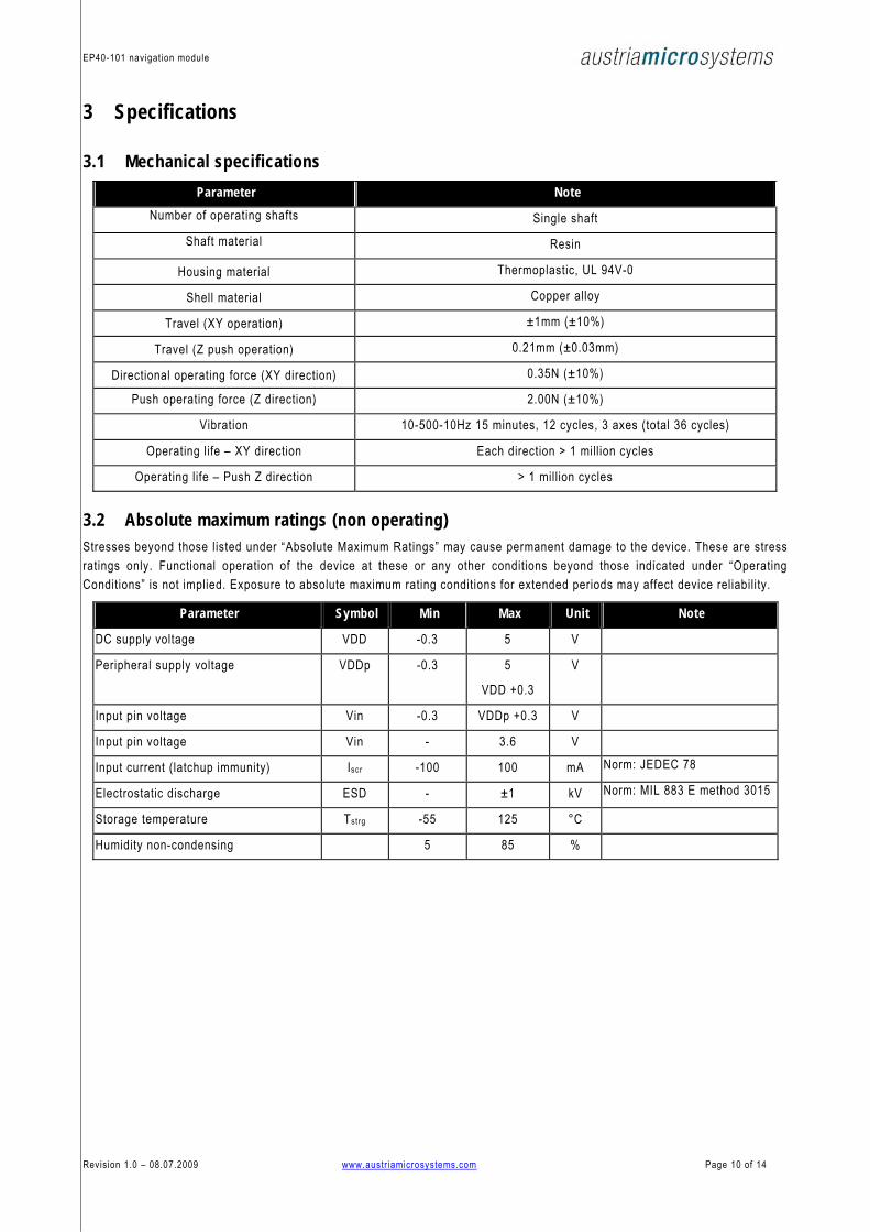
3 Specifications
3.1 Mechanical specifications Parameter Note
Number of operating shafts Single shaft Shaft material Resin
Housing material Thermoplastic, UL 94V-0
Shell material Copper alloy
Travel (XY operation) ±1mm (±10%)
Travel (Z push operation) 0.21mm (±0.03mm)
Directional operating force (XY direction) 0.35N (±10%)
Push operating force (Z direction) 2.00N (±10%)
Vibration 10-500-10Hz 15 minutes, 12 cycles, 3 axes (total 36 cycles)
Operating life – XY direction Each direction > 1 million cycles
Operating life – Push Z direction > 1 million cycles
3.2 Absolute maximum ratings (non operating) Stresses beyond those listed under “Absolute Maximum Ratings” may cause permanent damage to the device. These are stress ratings only. Functional operation of the device at these or any other conditions beyond those indicated under “Operating Conditions” is not implied. Exposure to absolute maximum rating conditions for extended periods may affect device reliability.
Parameter Symbol Min Max Unit Note
DC supply voltage VDD -0.3 5 V
Peripheral supply voltage VDDp -0.3 5
VDD +0.3
V
Input pin voltage Vin -0.3 VDDp +0.3 V
Input pin voltage Vin - 3.6 V
Input current (latchup immunity) Iscr -100 100 mA Norm: JEDEC 78
Electrostatic discharge ESD - ±1 kV Norm: MIL 883 E method 3015
Storage temperature Tstrg -55 125 °C
Humidity non-condensing 5 85 %
Revision 1.0 – 08.07.2009 www.austr iamicrosystems.com Page 10 of 14

EP40-101 navigation module
3.3 Electrical specifications
3.3.1 Operating conditions (operating conditions: Tamb = -20 to +80°C, VDD = 3.3V)
Parameter Symbol Min Typ Max Unit Note Core Supply voltage VDD 2.7 3.6 V
Peripheral Supply voltage VDDp 1.8 VDD +0.3
V open drain outputs : SCL, SDA, MDET
Current consumption on core supply, Shutdown mode
IDDs 50 µA average current pin VDD
Current consumption on core supply, Low Power mode
IDDl 200 µA average current pin VDD
Current consumption on core supply, Full Power mode
IDDf 8 mA average current pin VDD
Current consumption on IO supply IDDp 1 µA average current pin VDDp, 20ms i²C polling, 47k pullup resistor on SDA
Polling clock rate, Shutdown mode tP,W 65.6 80 94.4 ms internal
Polling clock rate, Low Power mode tP,A 16.4 20 23.6 ms internal
Coordinate conversion time 330 380 455 µs Full Power mode
Ambient temperature range Tamb -20 +80 °C
3.3.2 Digital IO pads DC/AC characteristics
Parameter Symbol Min Max Unit Note Inputs: SCL, SDA (receiver)
High level input voltage VIH 0.7 * VDDp V
0.3 * VDDp VDDp ≥ 2.7V Low level input voltage VIL
0.25 * VDDp V
VDDp < 2.7V Input leakage current ILEAK 1 µA VDDp = 3.6V Capacitive load CL 35 pF
Outputs: INTn, SDA (transmitter)
High level output voltage VOH Open drain Leakage current 1 µA Low level output voltage VOL VSS + 0.4 V -2mA
Revision 1.0 – 08.07.2009 www.austr iamicrosystems.com Page 11 of 14
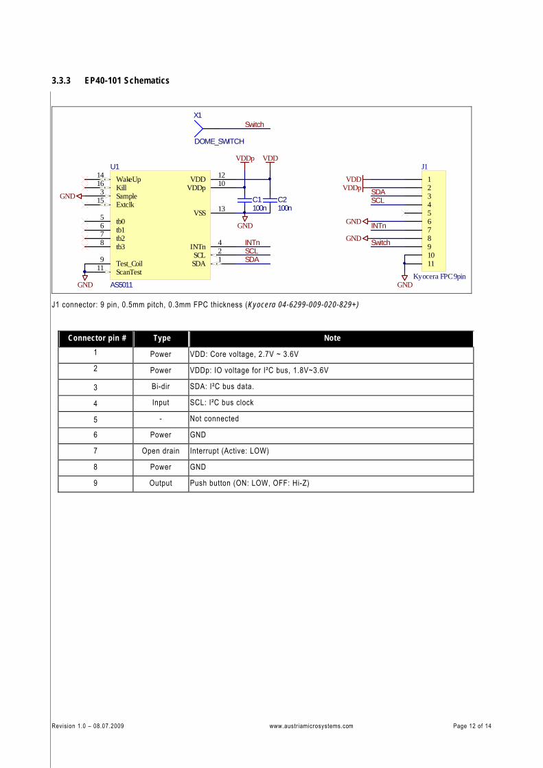
3.3.3 EP40-101 Schematics
SDA 1SCL 2
Sample3
INTn 4
tb05
tb16
tb27
tb38
Test_Coil9
VDDp 10
ScanTest11
VDD 12
VSS 13
WakeUp14
Extclk15
Kill16
U1
AS5011GND
GND
C2100n
VDDp
X1
DOME_SWITCH
C1100n
12345678910
VDD
SCLSDA
INTn
Switch
Switch
VDDVDDp
GND
SCLSDA
INTnGND
GND
GND
11
J1
Kyocera FPC 9pin
J1 connector: 9 pin, 0.5mm pitch, 0.3mm FPC thickness (Kyocera 04-6299-009-020-829+)
Connector pin # Type Note 1 Power VDD: Core voltage, 2.7V ~ 3.6V 2 Power VDDp: IO voltage for I²C bus, 1.8V~3.6V
3 Bi-dir SDA: I²C bus data.
4 Input SCL: I²C bus clock
5 - Not connected
6 Power GND
7 Open drain Interrupt (Active: LOW)
8 Power GND
9 Output Push button (ON: LOW, OFF: Hi-Z)
Revision 1.0 – 08.07.2009 www.austr iamicrosystems.com Page 12 of 14

EP40-101 navigation module
Table of contents
1 Mechanical drawing ........................................................................................................................................ 2 1.1 XY coordinates interpretation .............................................................................................................................3 1.2 Power modes.....................................................................................................................................................5
2 I²C interface .................................................................................................................................................... 8 2.1 Interface operation.............................................................................................................................................8 2.2 I²C Registers .....................................................................................................................................................9
3 Specifications ............................................................................................................................................... 10 3.1 Mechanical specifications................................................................................................................................. 10 3.2 Absolute maximum ratings (non operating) ........................................................................................................ 10 3.3 Electrical specifications ................................................................................................................................... 11
Revision History ..................................................................................................................................................... 13 Copyrights.............................................................................................................................................................. 14 Disclaimer .............................................................................................................................................................. 14 Contact Information ............................................................................................................................................... 14
Revision History Revision Date Description 1.0 July. 08.2009 • First revision
Revision 1.0 – 08.07.2009 www.austr iamicrosystems.com Page 13 of 14
EP40-101 navigation module
Copyrights Copyright © 1997-2009, austriamicrosystems AG, Schloss Premstaetten, 8141 Unterpremstaetten, Austria-Europe.
Trademarks Registered ®. All rights reserved. The material herein may not be reproduced, adapted, merged, translated, stored, or used without the prior written consent of the copyright owner.
All products and companies mentioned are trademarks or registered trademarks of their respective companies.
This product is covered by one or more patents registered to austriamicrosystems.
Disclaimer Devices sold by austriamicrosystems AG are covered by the warranty and patent indemnification provisions appearing in its Term of Sale. austriamicrosystems AG makes no warranty, express, statutory, implied, or by description regarding the information set forth herein or regarding the freedom of the described devices from patent infringement. austriamicrosystems AG reserves the right to change specifications and prices at any time and without notice. Therefore, prior to designing this product into a system, it is necessary to check with austriamicrosystems AG for current information. This product is intended for use in normal commercial applications. Applications requiring extended temperature range, unusual environmental requirements, or high reliability applications, such as military, medical life-support or lifesustaining equipment are specifically not recommended without additional processing by austriamicrosystems AG for each application.
The information furnished here by austriamicrosystems AG is believed to be correct and accurate. However, austriamicrosystems AG shall not be liable to recipient or any third party for any damages, including but not limited to personal injury, property damage, loss of profits, loss of use, interruption of business or indirect, special, incidental or consequential damages, of any kind, in connection with or arising out of the furnishing, performance or use of the technical data herein. No obligation or liability to recipient or any third party shall arise or flow out of austriamicrosystems AG rendering of technical or other services.
Contact Information Headquarters
austriamicrosystems AG
A-8141 Schloss Premstaetten, Austria
Tel: +43 (0) 3136 500 0
Fax: +43 (0) 3136 525 01
For Sales Offices, Distributors and Representatives, please visit:
http://www.austriamicrosystems.com
Revision 1.0 – 08.07.2009 www.austr iamicrosystems.com Page 14 of 14
Related Documents